Surface Roughness Measurement System Comparison Non-contact type Stylus type

Welcome message from author
This document is posted to help you gain knowledge. Please leave a comment to let me know what you think about it! Share it to your friends and learn new things together.
Transcript

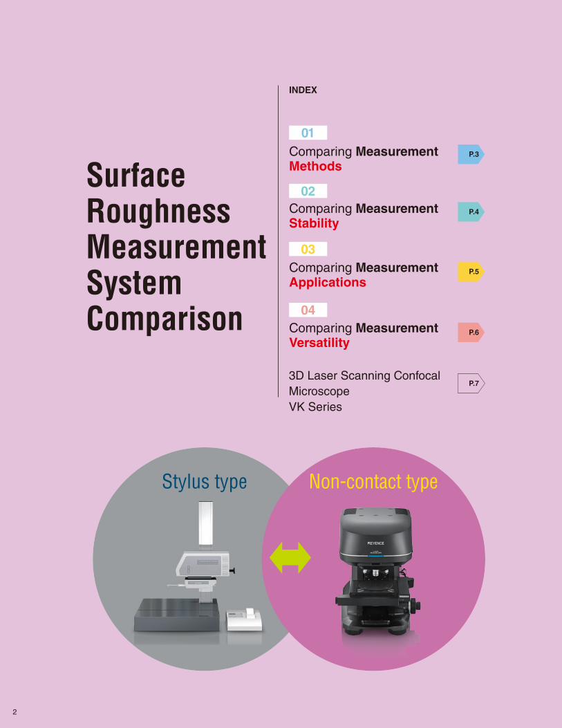
Surface Roughness Measurement System Comparison
Non-contact typeStylus type
Comparing Measurement Methods
Comparing Measurement Stability
Comparing Measurement Applications
Comparing Measurement Versatility
Surface Roughness Measurement System Comparison
INDEX
01
02
03
04
Non-contact typeStylus type
P.3
P.4
P.5
P.6
P.73D Laser Scanning Confocal MicroscopeVK Series
2
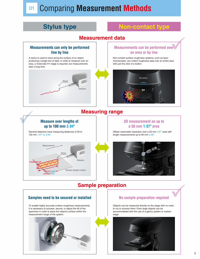
Measurement data
Measuring range
Sample preparation
Comparing Measurement Methods
Stylus
Displacement
100 mm 3.94" or 200 mm 7.87"
Detector
Sample (target) surface
Measurement
01
Stylus type Non-contact type
Measurements can only be performed line by line
Samples need to be secured or installed
Measure over lengths of up to 100 mm 3.94"
Measurements can be performed over an area or by line
No sample preparation required
3D measurement on up to a 50 mm 1.97" area
A stylus is used to trace along the surface of an object, producing a single line of data. In order to measure over an area, a motorized XY stage is required, but measurements take a long time.
To enable highly accurate surface roughness measurements, it is necessary to process, secure, or adjust the tilt of the specimen in order to place the object’s surface within the measurement range of the system.
General detectors have measuring distances of 50 to 100 mm 1.97" to 3.94".
Non-contact surface roughness systems, such as laser microscopes, can collect roughness data over an entire area with just the click of a button.
Objects can be measured directly on the stage with no need to cut or process them. Even large objects can be accommodated with the use of a gantry system or custom stage.
Obtain nanometer resolution over a 50 mm 1.97" area with length measurements up to 60 mm 2.36".
Stylus
Detector
3
It can be difficult to
successfully lower the stylus to
screw thread peaks and other
locations to measure.
Shape measurement systemSurface roughness
measurement system
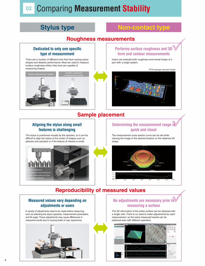
Roughness measurements
Sample placement
Reproducibility of measured values
Stylus type Non-contact type
Dedicated to only one specific type of measurement
Measured values vary depending on adjustments or users
Aligning the stylus along small features is challenging
Performs surface roughness and 3D form and contour measurements
No adjustments are necessary prior to measuring a surface
Determining the measurement range is quick and visual
There are a number of different tools that have varying stylus shapes and detector performance. Most are used to measure surface roughness while a few tools are capable of measuring shapes.
A variety of adjustments need to be made before measuring, such as selecting the stylus type/size, measurement parameters, and tilt angle. These adjustments may cause differences in measured results due to varying levels of user experience.
The stylus is positioned visually by the operator, so it can be difficult to align the stylus at the center of shapes such as spheres and cylinders or if the feature of interest is small.
Users can evaluate both roughness and overall shape of a part with a single system.
The 3D information of the entire surface can be obtained with a single click. There is no need to make adjustments for each measurement, so the same measured results can be obtained even with different operators.
The measurement cross section curve can be set while viewing the image of the desired location on the obtained 3D shape.
PCB warpage and part height
Comparing Measurement Stability02
4
55.248450.0000
40.0000
30.0000
20.0000
10.0000
0.0000
0.000 100.0000 300.0000 500.0000 700.0000 900.0000 1100.0000 1300.0000 1500.0000 1700.0000 1900.0000 2100.0000 2300.0000 2490.6355
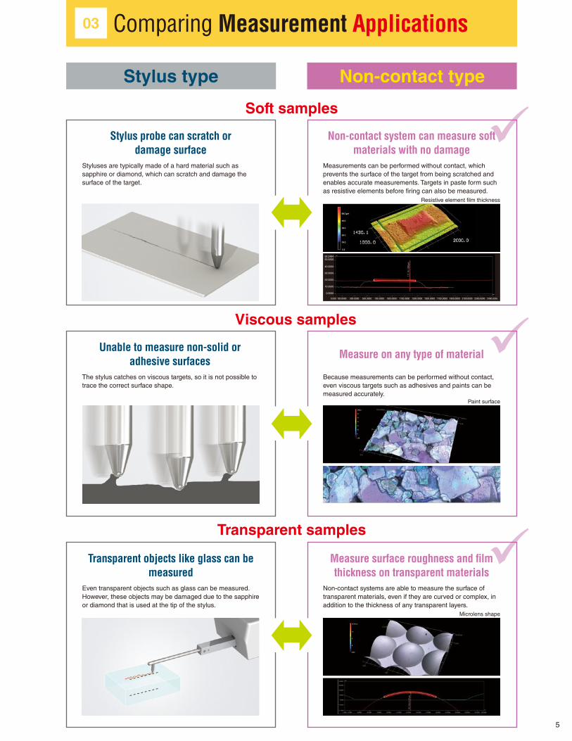
Soft samples
Viscous samples
Transparent samples
Stylus type Non-contact type
Stylus probe can scratch or damage surface
Transparent objects like glass can be measured
Unable to measure non-solid or adhesive surfaces
Non-contact system can measure soft materials with no damage
Measure surface roughness and film thickness on transparent materials
Measure on any type of material
Styluses are typically made of a hard material such as sapphire or diamond, which can scratch and damage the surface of the target.
Even transparent objects such as glass can be measured. However, these objects may be damaged due to the sapphire or diamond that is used at the tip of the stylus.
The stylus catches on viscous targets, so it is not possible to trace the correct surface shape.
Measurements can be performed without contact, which prevents the surface of the target from being scratched and enables accurate measurements. Targets in paste form such as resistive elements before firing can also be measured.
Non-contact systems are able to measure the surface of transparent materials, even if they are curved or complex, in addition to the thickness of any transparent layers.
Because measurements can be performed without contact, even viscous targets such as adhesives and paints can be measured accurately.
Paint surface
Microlens shape
Resistive element film thickness
Comparing Measurement Applications03
5
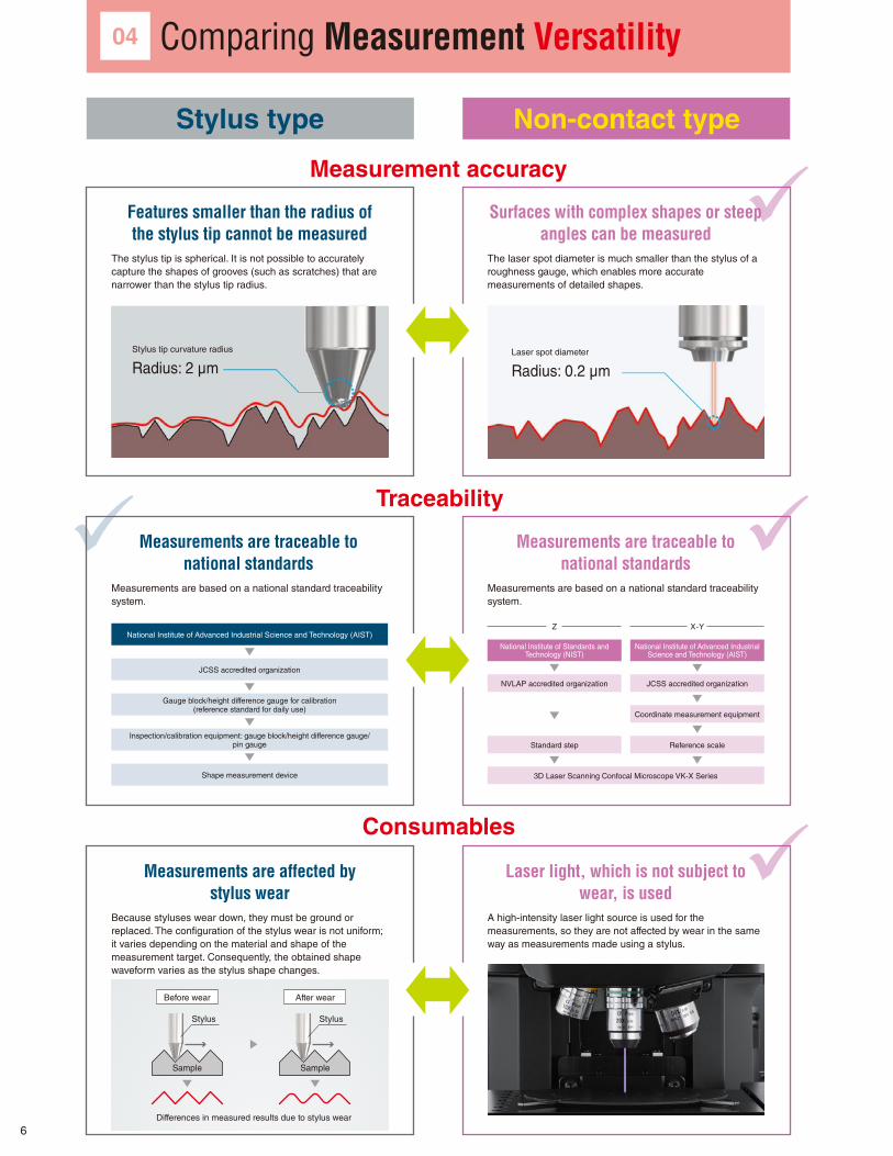
Stylus tip curvature radius
Radius: 2 μmLaser spot diameter
Radius: 0.2 μm
Differences in measured results due to stylus wear
Sample
Before wear After wear
Sample
Stylus Stylus
Measurement accuracy
Traceability
Consumables
Stylus type Non-contact type
Features smaller than the radius of the stylus tip cannot be measured
Measurements are affected by stylus wear
Measurements are traceable to national standards
Surfaces with complex shapes or steep angles can be measured
Laser light, which is not subject to wear, is used
Measurements are traceable to national standards
The stylus tip is spherical. It is not possible to accurately capture the shapes of grooves (such as scratches) that are narrower than the stylus tip radius.
Because styluses wear down, they must be ground or replaced. The configuration of the stylus wear is not uniform; it varies depending on the material and shape of the measurement target. Consequently, the obtained shape waveform varies as the stylus shape changes.
Measurements are based on a national standard traceability system.
The laser spot diameter is much smaller than the stylus of a roughness gauge, which enables more accurate measurements of detailed shapes.
A high-intensity laser light source is used for the measurements, so they are not affected by wear in the same way as measurements made using a stylus.
Measurements are based on a national standard traceability system.
National Institute of Advanced Industrial Science and Technology (AIST)
JCSS accredited organization
Gauge block/height difference gauge for calibration(reference standard for daily use)
Inspection/calibration equipment: gauge block/height difference gauge/ pin gauge
Shape measurement device
04
National Institute of Standards andTechnology (NIST)
NVLAP accredited organization
Z
Standard step
3D Laser Scanning Confocal Microscope VK-X Series
National Institute of Advanced IndustrialScience and Technology (AIST)
JCSS accredited organization
X-Y
Coordinate measurement equipment
Reference scale
Comparing Measurement Versatility
6

Transforming 3D Surface Metrology3D Laser Scanning Confocal Microscope
16-bit laser confocalXYZ traceability
Provides clear analysis of surface roughnessUp to 42 parameters for analyzing roughness are used to automatically compare multiple samples. Values such as Ra and Rz are automatically visualized in relation to each other. Instantly analyze previously undefined aspects used to quantify differences between targets, from judgment between good and bad products to analysis of samples made through different processing methods. With explanations attached to each parameter, any user is able to easily analyze surface texture.
Separate result files require longer analysis time and hinder
understanding. Combining the data in Excel can be time consuming.
Even though these parts feel and appear different, it is difficult to
judge which roughness parameter should be used in the evaluation.
There are no differences when using Ra and Rz.
You can arrange the samples you want to analyze and
specify the item to compare for analysis.
Roughness parameter variations can be checked visually.
Conventional Measurement Systems Conventional Measurement Systems
VK Series VK Series
■ Quickly Visualize and Quantify Differences between Surfaces
Good sample: Ra = 1.8 Bad sample: Ra = 1.8
VK-X Series Laser Microscope 3D Laser Scanning Confocal Microscope
3D Laser Scanning Confocal MicroscopeVK-X Series
7
E-mail: [email protected]
www.keyence.com
Copyright (c) 2018 KEYENCE CORPORATION. All rights reserved. VKSurfaceTesterComp-KA-TG2-US 1048-2 611G78
E-mail: [email protected]
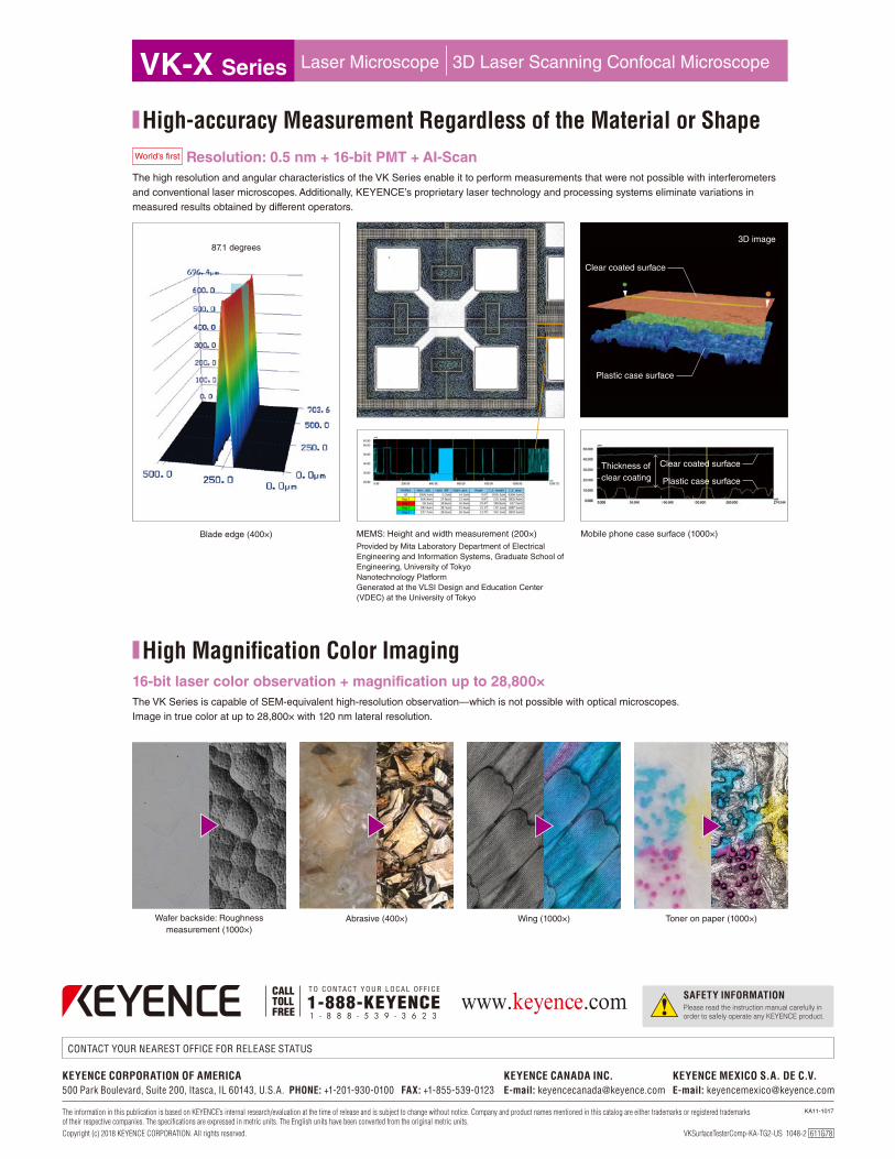
MEMS: Height and width measurement (200×)Provided by Mita Laboratory Department of ElectricalEngineering and Information Systems, Graduate School of Engineering, University of TokyoNanotechnology PlatformGenerated at the VLSI Design and Education Center(VDEC) at the University of Tokyo
Mobile phone case surface (1000×)
16-bit laser color observation + magnification up to 28,800×The VK Series is capable of SEM-equivalent high-resolution observation—which is not possible with optical microscopes.Image in true color at up to 28,800× with 120 nm lateral resolution.
Resolution: 0.5 nm + 16-bit PMT + AI-ScanThe high resolution and angular characteristics of the VK Series enable it to perform measurements that were not possible with interferometers and conventional laser microscopes. Additionally, KEYENCE’s proprietary laser technology and processing systems eliminate variations in measured results obtained by different operators.
87.1 degrees
World’s first
Blade edge (400×)
Wafer backside: Roughnessmeasurement (1000×)
Abrasive (400×) Wing (1000×) Toner on paper (1000×)
3D image
Clear coated surface
Plastic case surface
Thickness of clear coating
Clear coated surface
Plastic case surface
■ High-accuracy Measurement Regardless of the Material or Shape
■ High Magnification Color Imaging
VK-X Series Laser Microscope 3D Laser Scanning Confocal Microscope
Related Documents