Page 1 of 4 Notes A. Performance and quality attributes and conditions not expressly stated in this specification document are intended to be excluded and do not form a part of this specification document. B. Electrical specifications and performance data contained in this specification document are based on Mini-Circuit’s applicable established test performance criteria and measurement instructions. C. The parts covered by this specification document are subject to Mini-Circuits standard limited warranty and terms and conditions (collectively, “Standard Terms”); Purchasers of this part are entitled to the rights and benefits contained therein. For a full statement of the Standard Terms and the exclusive rights and remedies thereunder, please visit Mini-Circuits’ website at www.minicircuits.com/MCLStore/terms.jsp Mini-Circuits ® www.minicircuits.com P.O. Box 350166, Brooklyn, NY 11235-0003 (718) 934-4500 [email protected] Surface Mount Monolithic Amplifier Product Features • DC-4 GHz • Single Voltage Supply • Internally matched to 50 Ohms • Unconditionally Stable • Low Performance Variation Over Temperature • Transient protected • Aqueous washable • Protected by US Patent 6,943,629 • Low additive phase noise, typically -170 dBc/Hz @10 KHz offset Typical Applications • Cellular/ PCS/ 3G Base Station • CATV, Cable Modem & DBS • Fixed Wireless & WLAN • Microwave Radio & Test Equipment • Suitable for low phase noise applications Rev. S ECO-009719 ERA-5SM+ 210915 simplified schematic and pin description Function Pin Number Description RF IN 1 RF input pin. This pin requires the use of an external DC blocking capacitor chosen for the frequency of operation. RF-OUT and DC-IN 3 RF output and bias pin. DC voltage is present on this pin; therefore a DC blocking capacitor is necessary for proper operation. An RF choke is needed to feed DC bias without loss of RF signal due to the bias connection, as shown in “Recommended Application Circuit”. GND 2,4 Connections to ground. Use via holes as shown in “Suggested Layout for PCB Design” to reduce ground path inductance for best performance. General Description ERA-5SM+ (RoHS compliant) is a wideband amplifier offering high dynamic range. It has repeatable per- formance from lot to lot. It is enclosed in an Micro-X package. ERA-5SM+ uses Darlington configuration and is fabricated using InGaP HBT technology. Expected MTTF is 850 years at 85°C case temperature. GROUND RF IN RF-OUT and DC-IN GND GND RF-OUT and DC-IN RF IN 1 2 3 4 DC-4 GHz ERA-5SM+ +RoHS Compliant The +Suffix identifies RoHS Compliance. See our web site for RoHS Compliance methodologies and qualifications CASE STYLE: WW107 Generic photo used for illustration purposes only

Welcome message from author
This document is posted to help you gain knowledge. Please leave a comment to let me know what you think about it! Share it to your friends and learn new things together.
Transcript

Page 1 of 4
NotesA. Performance and quality attributes and conditions not expressly stated in this specification document are intended to be excluded and do not form a part of this specification document. B. Electrical specifications and performance data contained in this specification document are based on Mini-Circuit’s applicable established test performance criteria and measurement instructions. C. The parts covered by this specification document are subject to Mini-Circuits standard limited warranty and terms and conditions (collectively, “Standard Terms”); Purchasers of this part are entitled to the rights and benefits contained therein. For a full statement of the Standard Terms and the exclusive rights and remedies thereunder, please visit Mini-Circuits’ website at www.minicircuits.com/MCLStore/terms.jsp
Mini-Circuits®
www.minicircuits.com P.O. Box 350166, Brooklyn, NY 11235-0003 (718) 934-4500 [email protected]
Surface Mount
Monolithic AmplifierProduct Features• DC-4 GHz • Single Voltage Supply• Internally matched to 50 Ohms• Unconditionally Stable• Low Performance Variation Over Temperature• Transient protected• Aqueous washable• Protected by US Patent 6,943,629• Low additive phase noise, typically -170 dBc/Hz @10 KHz offset
Typical Applications• Cellular/ PCS/ 3G Base Station• CATV, Cable Modem & DBS• Fixed Wireless & WLAN• Microwave Radio & Test Equipment• Suitable for low phase noise applications
Rev. SECO-009719ERA-5SM+210915
simplified schematic and pin description
Function Pin Number Description
RF IN 1 RF input pin. This pin requires the use of an external DC blocking capacitor chosen for the frequency of operation.
RF-OUT and DC-IN 3
RF output and bias pin. DC voltage is present on this pin; therefore a DC blocking capacitor is necessary for proper operation. An RF choke is needed to feed DC bias without loss of RF signal due to the bias connection, as shown in “Recommended Application Circuit”.
GND 2,4 Connections to ground. Use via holes as shown in “Suggested Layout for PCB Design” to reduce ground path inductance for best performance.
General DescriptionERA-5SM+ (RoHS compliant) is a wideband amplifier offering high dynamic range. It has repeatable per-formance from lot to lot. It is enclosed in an Micro-X package. ERA-5SM+ uses Darlington configuration and is fabricated using InGaP HBT technology. Expected MTTF is 850 years at 85°C case temperature.
GROUND
RF IN
RF-OUT and DC-IN
GND GND
RF-OUT and DC-IN
RF IN 1
2
3
4
DC-4 GHz
ERA-5SM+
+RoHS CompliantThe +Suffix identifies RoHS Compliance. See our web site for RoHS Compliance methodologies and qualifications
CASE STYLE: WW107
Generic photo used for illustration purposes only

Monolithic InGaP HBT MMIC Amplifier
NotesA. Performance and quality attributes and conditions not expressly stated in this specification document are intended to be excluded and do not form a part of this specification document. B. Electrical specifications and performance data contained in this specification document are based on Mini-Circuit’s applicable established test performance criteria and measurement instructions. C. The parts covered by this specification document are subject to Mini-Circuits standard limited warranty and terms and conditions (collectively, “Standard Terms”); Purchasers of this part are entitled to the rights and benefits contained therein. For a full statement of the Standard Terms and the exclusive rights and remedies thereunder, please visit Mini-Circuits’ website at www.minicircuits.com/MCLStore/terms.jsp
Mini-Circuits®
www.minicircuits.com P.O. Box 350166, Brooklyn, NY 11235-0003 (718) 934-4500 [email protected] Page 2 of 4
Electrical Specifications at 25°C and 65mA, unless notedParameter Min. Typ. Max. Units CpkFrequency Range* DC 4 GHz
Gain f=0.1GHzf=1 GHzf=2 GHzf=3 GHzf=4 GHz
19—16—12
20.219.517.615.614
22 dB >1.5
Magnitude of Gain Variation versus Temperature(values are negative)
f=0.1GHzf=1 GHzf=2 GHzf=3 GHzf=4 GHz
—————
.0025
.0034
.0043
.0052
.0065
.005
.007.0085.0105.013
dB/°C
Input Return Loss f=0.1 GHzf=2 GHzf=4 GHz
212321
dB
Output Return Loss f=0.1 GHzf=2 GHzf=4 GHz
302617
dB
Reverse Isolation f=2 GHz 19 22 — dB
Output Power @1 dB compression f=0.1 GHzf=1 GHzf=2 GHzf=4 GHz
16.516.515.5
18.418.417
12.5
————
dBm >1.5
Saturated Output Power (at 3dB compression)
f=0.1 GHzf=1 GHzf=2 GHz
19.518.518
dBm
Output IP3 f=0.1 GHzf=1 GHzf=2 GHzf=4 GHz
303026—
33333026
————
dBm >1.5
Noise Figure f=0.1GHzf=2 GHzf=4 GHz
3.53.53.5
4.54.54.5
dB >1.5
Additive Phase Noise 2 GHz, 10 KHz offset — -170 — dBc/Hz
Group Delay f=2 GHz 90 psec
Recommended Device Operating Current 65 mA
Device Operating Voltage 4.5 4.9 5.3 V >1.5
Device Voltage Variation vs. Temperature at 65mA -3.2 mV/°C
Device Voltage Variation vs. Current at 25°C 6.9 mV/mA
Thermal Resistance, junction-to-case1 133 °C/W
Absolute Maximum RatingsParameter Ratings
Operating Temperature* -45°C to 85°C
Storage Temperature -65°C to 150°C
Operating Current 85mA
Power Dissipation 451mW
Input Power 13 dBm
Note: Permanent damage may occur if any of these limits are exceeded. These ratings are not intended for continuous normal operation.1Case is defined as ground leads.*Based on typical case temperature rise 10°C above ambient.
*Guaranteed specification DC-4 GHz. Low frequency cut off determined by external coupling capacitors.
ERA-5SM+
Monolithic InGaP HBT MMIC Amplifier
NotesA. Performance and quality attributes and conditions not expressly stated in this specification document are intended to be excluded and do not form a part of this specification document. B. Electrical specifications and performance data contained in this specification document are based on Mini-Circuit’s applicable established test performance criteria and measurement instructions. C. The parts covered by this specification document are subject to Mini-Circuits standard limited warranty and terms and conditions (collectively, “Standard Terms”); Purchasers of this part are entitled to the rights and benefits contained therein. For a full statement of the Standard Terms and the exclusive rights and remedies thereunder, please visit Mini-Circuits’ website at www.minicircuits.com/MCLStore/terms.jsp
Mini-Circuits®
www.minicircuits.com P.O. Box 350166, Brooklyn, NY 11235-0003 (718) 934-4500 [email protected] Page 3 of 4
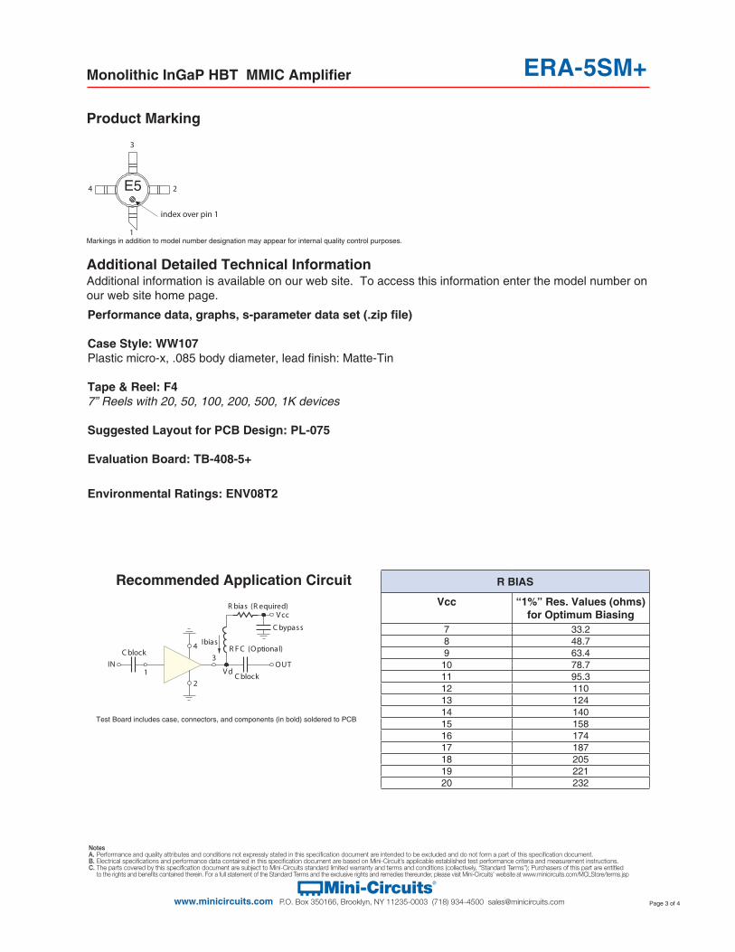
Product Marking
R BIAS
Vcc “1%” Res. Values (ohms)for Optimum Biasing
7 33.28 48.79 63.4
10 78.711 95.312 11013 12414 14015 15816 17417 18718 20519 22120 232
Recommended Application Circuit
4
2
3
1
C block
IN
C block
Ibias
OUTV d
R F C (Optional)
C bypass
V ccR bias (R equired)
Test Board includes case, connectors, and components (in bold) soldered to PCB
Additional Detailed Technical InformationAdditional information is available on our web site. To access this information enter the model number on our web site home page.
E5
1
2
3
4
index over pin 1
Markings in addition to model number designation may appear for internal quality control purposes.
Performance data, graphs, s-parameter data set (.zip file)
Case Style: WW107Plastic micro-x, .085 body diameter, lead finish: Matte-Tin
Tape & Reel: F47” Reels with 20, 50, 100, 200, 500, 1K devices
Suggested Layout for PCB Design: PL-075
Evaluation Board: TB-408-5+
Environmental Ratings: ENV08T2
ERA-5SM+

Monolithic InGaP HBT MMIC Amplifier
NotesA. Performance and quality attributes and conditions not expressly stated in this specification document are intended to be excluded and do not form a part of this specification document. B. Electrical specifications and performance data contained in this specification document are based on Mini-Circuit’s applicable established test performance criteria and measurement instructions. C. The parts covered by this specification document are subject to Mini-Circuits standard limited warranty and terms and conditions (collectively, “Standard Terms”); Purchasers of this part are entitled to the rights and benefits contained therein. For a full statement of the Standard Terms and the exclusive rights and remedies thereunder, please visit Mini-Circuits’ website at www.minicircuits.com/MCLStore/terms.jsp
Mini-Circuits®
www.minicircuits.com P.O. Box 350166, Brooklyn, NY 11235-0003 (718) 934-4500 [email protected] Page 4 of 4
ESD RatingHuman Body Model (HBM): Class 1B (500 v to < 1,000 v) in accordance with ANSI/ESD STM 5.1 - 2001
Machine Model (MM): Class M1 (< 100 v) in accordance with ANSI/ESD STM 5.2 - 1999
MSL RatingMoisture Sensitivity: MSL1 in accordance with IPC/JEDECJ-STD-020C
NO. TEST REQUIRED CONDITION STANDARD QUANTITY
1 Visual Inspection Low Power MicroscopeMagnification 40x
MIP-IN-0003(MCT spec) 45 units
2 Electrical Test Room Temperature SCD(MCL spec) 45 units
3 SAM Analysis Less than 10% growth in term of delamination
J-Std-020C(Jedec Standard) 45 units
4 Moisture SensitivityLevel 1
Bake at 125°C for 24 hoursSoak at 85°C/85%RH for 168 hoursReflow 3 cycles at 260°C peak
J-Std-020C(Jedec Standard) 45 units
MSL Test Flow Chart
VisualInspection Electrical Test SAM Analysis
Reflow 3 cycles,260°C
Soak85°C/85RH168 hours
Bake at 125°C,24 hours
VisualInspection Electrical Test SAM Analysis
Start
Stop
ERA-5SM+
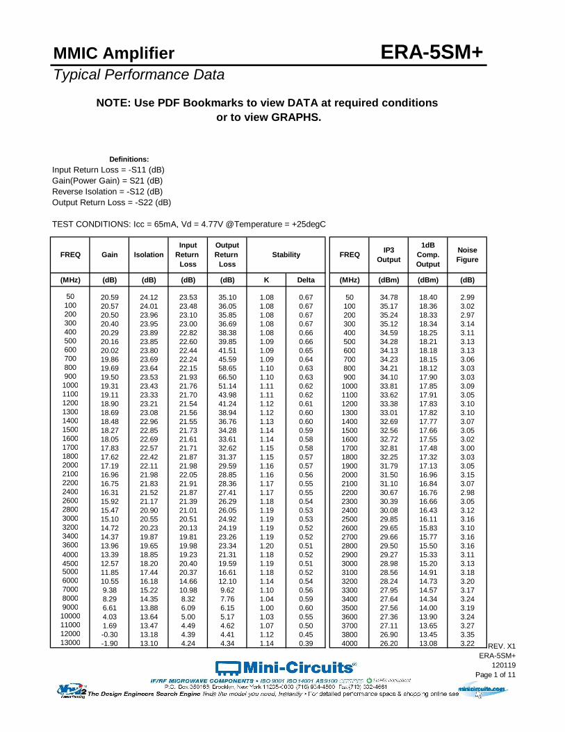
ERA-5SM+Typical Performance Data
(MHz) (dB) (dB) (dB) (dB) K Delta (MHz) (dBm) (dBm) (dB)
50 20.59 24.12 23.53 35.10 1.08 0.67 50 34.78 18.40 2.99100 20.57 24.01 23.48 36.05 1.08 0.67 100 35.17 18.36 3.02200 20.50 23.96 23.10 35.85 1.08 0.67 200 35.24 18.33 2.97300 20.40 23.95 23.00 36.69 1.08 0.67 300 35.12 18.34 3.14400 20.29 23.89 22.82 38.38 1.08 0.66 400 34.59 18.25 3.11500 20.16 23.85 22.60 39.85 1.09 0.66 500 34.28 18.21 3.13600 20.02 23.80 22.44 41.51 1.09 0.65 600 34.13 18.18 3.13700 19.86 23.69 22.24 45.59 1.09 0.64 700 34.23 18.15 3.06800 19.69 23.64 22.15 58.65 1.10 0.63 800 34.21 18.12 3.03900 19.50 23.53 21.93 66.50 1.10 0.63 900 34.10 17.90 3.031000 19.31 23.43 21.76 51.14 1.11 0.62 1000 33.81 17.85 3.091100 19.11 23.33 21.70 43.98 1.11 0.62 1100 33.62 17.91 3.051200 18.90 23.21 21.54 41.24 1.12 0.61 1200 33.38 17.83 3.101300 18.69 23.08 21.56 38.94 1.12 0.60 1300 33.01 17.82 3.101400 18.48 22.96 21.55 36.76 1.13 0.60 1400 32.69 17.77 3.071500 18.27 22.85 21.73 34.28 1.14 0.59 1500 32.56 17.66 3.051600 18.05 22.69 21.61 33.61 1.14 0.58 1600 32.72 17.55 3.021700 17.83 22.57 21.71 32.62 1.15 0.58 1700 32.81 17.48 3.001800 17.62 22.42 21.87 31.37 1.15 0.57 1800 32.25 17.32 3.032000 17.19 22.11 21.98 29.59 1.16 0.57 1900 31.79 17.13 3.052100 16.96 21.98 22.05 28.85 1.16 0.56 2000 31.50 16.96 3.152200 16.75 21.83 21.91 28.36 1.17 0.55 2100 31.10 16.84 3.072400 16.31 21.52 21.87 27.41 1.17 0.55 2200 30.67 16.76 2.982600 15.92 21.17 21.39 26.29 1.18 0.54 2300 30.39 16.66 3.052800 15.47 20.90 21.01 26.05 1.19 0.53 2400 30.08 16.43 3.123000 15.10 20.55 20.51 24.92 1.19 0.53 2500 29.85 16.11 3.163200 14.72 20.23 20.13 24.19 1.19 0.52 2600 29.65 15.83 3.103400 14.37 19.87 19.81 23.26 1.19 0.52 2700 29.66 15.77 3.163600 13.96 19.65 19.98 23.34 1.20 0.51 2800 29.50 15.50 3.164000 13.39 18.85 19.23 21.31 1.18 0.52 2900 29.27 15.33 3.114500 12.57 18.20 20.40 19.59 1.19 0.51 3000 28.98 15.20 3.135000 11.85 17.44 20.37 16.61 1.18 0.52 3100 28.56 14.91 3.186000 10.55 16.18 14.66 12.10 1.14 0.54 3200 28.24 14.73 3.207000 9.38 15.22 10.98 9.62 1.10 0.56 3300 27.95 14.57 3.178000 8.29 14.35 8.32 7.76 1.04 0.59 3400 27.64 14.34 3.249000 6.61 13.88 6.09 6.15 1.00 0.60 3500 27.56 14.00 3.1910000 4.03 13.64 5.00 5.17 1.03 0.55 3600 27.36 13.90 3.2411000 1.69 13.47 4.49 4.62 1.07 0.50 3700 27.11 13.65 3.2712000 -0.30 13.18 4.39 4.41 1.12 0.45 3800 26.90 13.45 3.3513000 -1.90 13.10 4.24 4.34 1.14 0.39 4000 26.20 13.08 3.22
Gain(Power Gain) = S21 (dB)Reverse Isolation = -S12 (dB)Output Return Loss = -S22 (dB)
TEST CONDITIONS: Icc = 65mA, Vd = 4.77V @Temperature = +25degC
MMIC Amplifier
Definitions:Input Return Loss = -S11 (dB)
IP3OutputFREQ
NOTE: Use PDF Bookmarks to view DATA at required conditions or to view GRAPHS.
InputReturn
Loss
OutputReturn
LossIsolation FREQGain Noise
Figure
1dBComp.Output
Stability
REV. X1ERA-5SM+
120119Page 1 of 11
MMIC Amplifier ERA-5SM+Typical Performance Data
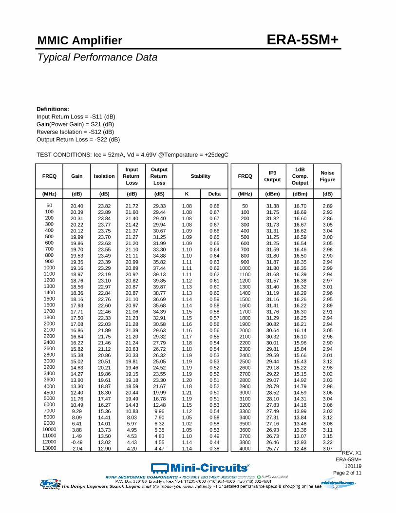
Definitions:Input Return Loss = -S11 (dB)Gain(Power Gain) = S21 (dB)Reverse Isolation = -S12 (dB)Output Return Loss = -S22 (dB)
TEST CONDITIONS: Icc = 52mA, Vd = 4.69V @Temperature = +25degC
(MHz) (dB) (dB) (dB) (dB) K Delta (MHz) (dBm) (dBm) (dB)
50 20.40 23.82 21.72 29.33 1.08 0.68 50 31.38 16.70 2.89100 20.39 23.89 21.60 29.44 1.08 0.67 100 31.75 16.69 2.93200 20.31 23.84 21.40 29.40 1.08 0.67 200 31.82 16.60 2.86300 20.22 23.77 21.42 29.94 1.08 0.67 300 31.73 16.67 3.05400 20.12 23.75 21.37 30.67 1.09 0.66 400 31.31 16.62 3.04500 19.99 23.70 21.27 31.25 1.09 0.65 500 31.25 16.59 3.00600 19.86 23.63 21.20 31.99 1.09 0.65 600 31.25 16.54 3.05700 19.70 23.55 21.10 33.30 1.10 0.64 700 31.59 16.46 2.98800 19.53 23.49 21.11 34.88 1.10 0.64 800 31.80 16.50 2.90900 19.35 23.39 20.99 35.82 1.11 0.63 900 31.87 16.35 2.941000 19.16 23.29 20.89 37.44 1.11 0.62 1000 31.80 16.35 2.991100 18.97 23.19 20.92 39.13 1.11 0.62 1100 31.68 16.39 2.941200 18.76 23.10 20.82 39.85 1.12 0.61 1200 31.57 16.38 2.971300 18.56 22.97 20.87 39.87 1.13 0.60 1300 31.40 16.32 3.011400 18.36 22.84 20.87 38.77 1.13 0.60 1400 31.19 16.29 2.961500 18.16 22.76 21.10 36.69 1.14 0.59 1500 31.16 16.26 2.951600 17.93 22.60 20.97 35.68 1.14 0.58 1600 31.41 16.22 2.891700 17.71 22.46 21.06 34.39 1.15 0.58 1700 31.76 16.30 2.911800 17.50 22.33 21.23 32.91 1.15 0.57 1800 31.29 16.25 2.942000 17.08 22.03 21.28 30.58 1.16 0.56 1900 30.82 16.21 2.942100 16.86 21.89 21.39 29.63 1.16 0.56 2000 30.64 16.14 3.052200 16.64 21.75 21.20 29.32 1.17 0.55 2100 30.32 16.10 2.962400 16.22 21.46 21.24 27.79 1.18 0.54 2200 30.01 15.96 2.902600 15.82 21.12 20.63 26.72 1.18 0.54 2300 29.81 15.84 2.942800 15.38 20.86 20.33 26.32 1.19 0.53 2400 29.59 15.66 3.013000 15.02 20.51 19.81 25.05 1.19 0.53 2500 29.44 15.43 3.123200 14.63 20.21 19.46 24.52 1.19 0.52 2600 29.18 15.22 2.983400 14.27 19.86 19.15 23.55 1.19 0.52 2700 29.22 15.15 3.023600 13.90 19.61 19.18 23.30 1.20 0.51 2800 29.07 14.92 3.034000 13.30 18.87 18.59 21.67 1.18 0.52 2900 28.79 14.79 2.984500 12.40 18.30 20.44 19.99 1.21 0.50 3000 28.52 14.59 3.065000 11.76 17.47 19.49 16.78 1.19 0.51 3100 28.10 14.31 3.046000 10.49 16.27 14.43 12.48 1.15 0.53 3200 27.83 14.16 3.067000 9.29 15.36 10.83 9.96 1.12 0.54 3300 27.49 13.99 3.038000 8.09 14.41 8.03 7.90 1.05 0.58 3400 27.31 13.84 3.129000 6.41 14.01 5.97 6.32 1.02 0.58 3500 27.16 13.48 3.0810000 3.88 13.73 4.95 5.35 1.05 0.53 3600 26.93 13.36 3.1111000 1.49 13.50 4.53 4.83 1.10 0.49 3700 26.73 13.07 3.1512000 -0.49 13.02 4.43 4.55 1.14 0.44 3800 26.46 12.93 3.2213000 -2.04 12.90 4.20 4.47 1.14 0.38 4000 25.77 12.48 3.07
FREQ NoiseFigure
1dBComp.Output
IP3OutputFREQIsolation StabilityGain
InputReturn
Loss
OutputReturn
Loss
REV. X1ERA-5SM+
120119Page 2 of 11

MMIC Amplifier ERA-5SM+Typical Performance Data
Definitions:Input Return Loss = -S11 (dB)Gain(Power Gain) = S21 (dB)Reverse Isolation = -S12 (dB)Output Return Loss = -S22 (dB)
TEST CONDITIONS: Icc = 78mA, Vd = 4.84V @Temperature = +25degC
(MHz) (dB) (dB) (dB) (dB) K Delta (MHz) (dBm) (dBm) (dB)
50 20.72 24.09 25.12 44.79 1.07 0.68 50 37.51 19.34 3.07100 20.70 24.19 24.95 47.10 1.08 0.67 100 37.90 19.36 3.09200 20.62 24.09 24.50 47.52 1.08 0.67 200 37.88 19.32 3.05300 20.53 24.07 24.29 48.87 1.08 0.67 300 37.52 19.36 3.23400 20.42 24.02 24.03 50.48 1.08 0.66 400 36.86 19.15 3.20500 20.28 23.95 23.66 48.50 1.09 0.66 500 36.05 19.11 3.18600 20.13 23.88 23.39 46.37 1.09 0.65 600 35.60 19.09 3.21700 19.97 23.79 23.05 43.10 1.09 0.64 700 35.32 19.10 3.16800 19.80 23.73 22.91 39.49 1.10 0.64 800 34.99 18.97 3.12900 19.61 23.63 22.59 39.17 1.10 0.63 900 34.66 18.58 3.121000 19.41 23.52 22.32 37.65 1.11 0.62 1000 34.30 18.51 3.171100 19.21 23.40 22.23 36.01 1.11 0.62 1100 34.06 18.55 3.121200 19.00 23.28 22.00 35.13 1.12 0.61 1200 33.73 18.50 3.181300 18.79 23.17 22.03 34.17 1.12 0.60 1300 33.29 18.44 3.201400 18.57 23.03 21.97 33.10 1.13 0.60 1400 32.97 18.33 3.161500 18.36 22.93 22.15 31.50 1.13 0.59 1500 32.76 18.15 3.141600 18.14 22.76 22.04 31.31 1.14 0.59 1600 32.83 18.02 3.121700 17.91 22.62 22.13 30.61 1.14 0.58 1700 32.74 17.91 3.101800 17.69 22.48 22.34 29.77 1.15 0.57 1800 32.22 17.69 3.112000 17.26 22.17 22.48 28.52 1.15 0.57 1900 31.80 17.46 3.122100 17.03 22.03 22.55 27.91 1.16 0.56 2000 31.55 17.28 3.202200 16.82 21.86 22.42 27.62 1.16 0.56 2100 31.19 17.17 3.182400 16.39 21.57 22.43 26.79 1.17 0.55 2200 30.72 17.11 3.092600 15.99 21.21 22.04 25.85 1.17 0.54 2300 30.38 17.03 3.192800 15.54 20.92 21.61 25.65 1.18 0.53 2400 30.13 16.82 3.253000 15.17 20.57 21.11 24.61 1.18 0.53 2500 29.81 16.46 3.273200 14.79 20.26 20.73 23.94 1.19 0.53 2600 29.67 16.19 3.173400 14.44 19.87 20.42 22.98 1.18 0.53 2700 29.63 16.15 3.233600 14.02 19.65 20.59 23.00 1.20 0.52 2800 29.47 15.87 3.264000 13.45 18.87 19.81 21.17 1.18 0.53 2900 29.28 15.73 3.204500 12.63 18.18 21.08 19.28 1.18 0.52 3000 29.03 15.63 3.245000 11.89 17.50 21.54 16.55 1.18 0.52 3100 28.59 15.36 3.276000 10.66 16.16 15.07 12.00 1.14 0.55 3200 28.34 15.13 3.297000 9.51 15.16 11.14 9.44 1.09 0.57 3300 28.00 14.98 3.278000 8.41 14.29 8.48 7.54 1.03 0.61 3400 27.76 14.78 3.339000 6.71 13.85 6.08 5.85 0.99 0.62 3500 27.60 14.41 3.3110000 4.20 13.66 4.99 4.97 1.02 0.57 3600 27.44 14.28 3.3511000 1.79 13.41 4.56 4.56 1.07 0.51 3700 27.22 14.06 3.3912000 -0.21 12.95 4.49 4.45 1.11 0.45 3800 26.94 13.85 3.4513000 -1.79 12.93 4.34 4.37 1.13 0.39 4000 26.27 13.49 3.37
FREQ NoiseFigure
1dBComp.Output
IP3OutputIsolation StabilityGain
InputReturn
Loss
OutputReturn
LossFREQ
REV. X1ERA-5SM+
120119Page 3 of 11
MMIC Amplifier ERA-5SM+Typical Performance Data
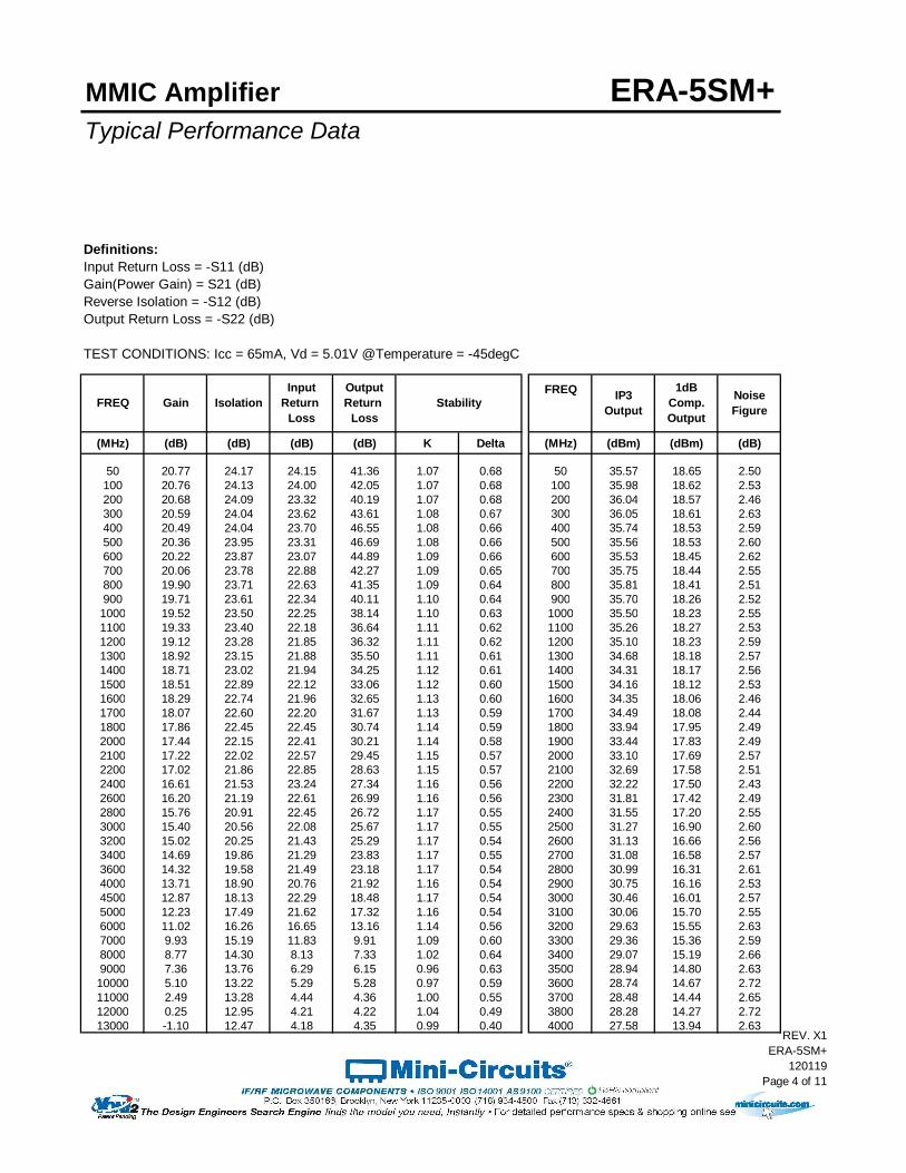
Definitions:Input Return Loss = -S11 (dB)Gain(Power Gain) = S21 (dB)Reverse Isolation = -S12 (dB)Output Return Loss = -S22 (dB)
TEST CONDITIONS: Icc = 65mA, Vd = 5.01V @Temperature = -45degC
FREQ
(MHz) (dB) (dB) (dB) (dB) K Delta (MHz) (dBm) (dBm) (dB)
50 20.77 24.17 24.15 41.36 1.07 0.68 50 35.57 18.65 2.50100 20.76 24.13 24.00 42.05 1.07 0.68 100 35.98 18.62 2.53200 20.68 24.09 23.32 40.19 1.07 0.68 200 36.04 18.57 2.46300 20.59 24.04 23.62 43.61 1.08 0.67 300 36.05 18.61 2.63400 20.49 24.04 23.70 46.55 1.08 0.66 400 35.74 18.53 2.59500 20.36 23.95 23.31 46.69 1.08 0.66 500 35.56 18.53 2.60600 20.22 23.87 23.07 44.89 1.09 0.66 600 35.53 18.45 2.62700 20.06 23.78 22.88 42.27 1.09 0.65 700 35.75 18.44 2.55800 19.90 23.71 22.63 41.35 1.09 0.64 800 35.81 18.41 2.51900 19.71 23.61 22.34 40.11 1.10 0.64 900 35.70 18.26 2.521000 19.52 23.50 22.25 38.14 1.10 0.63 1000 35.50 18.23 2.551100 19.33 23.40 22.18 36.64 1.11 0.62 1100 35.26 18.27 2.531200 19.12 23.28 21.85 36.32 1.11 0.62 1200 35.10 18.23 2.591300 18.92 23.15 21.88 35.50 1.11 0.61 1300 34.68 18.18 2.571400 18.71 23.02 21.94 34.25 1.12 0.61 1400 34.31 18.17 2.561500 18.51 22.89 22.12 33.06 1.12 0.60 1500 34.16 18.12 2.531600 18.29 22.74 21.96 32.65 1.13 0.60 1600 34.35 18.06 2.461700 18.07 22.60 22.20 31.67 1.13 0.59 1700 34.49 18.08 2.441800 17.86 22.45 22.45 30.74 1.14 0.59 1800 33.94 17.95 2.492000 17.44 22.15 22.41 30.21 1.14 0.58 1900 33.44 17.83 2.492100 17.22 22.02 22.57 29.45 1.15 0.57 2000 33.10 17.69 2.572200 17.02 21.86 22.85 28.63 1.15 0.57 2100 32.69 17.58 2.512400 16.61 21.53 23.24 27.34 1.16 0.56 2200 32.22 17.50 2.432600 16.20 21.19 22.61 26.99 1.16 0.56 2300 31.81 17.42 2.492800 15.76 20.91 22.45 26.72 1.17 0.55 2400 31.55 17.20 2.553000 15.40 20.56 22.08 25.67 1.17 0.55 2500 31.27 16.90 2.603200 15.02 20.25 21.43 25.29 1.17 0.54 2600 31.13 16.66 2.563400 14.69 19.86 21.29 23.83 1.17 0.55 2700 31.08 16.58 2.573600 14.32 19.58 21.49 23.18 1.17 0.54 2800 30.99 16.31 2.614000 13.71 18.90 20.76 21.92 1.16 0.54 2900 30.75 16.16 2.534500 12.87 18.13 22.29 18.48 1.17 0.54 3000 30.46 16.01 2.575000 12.23 17.49 21.62 17.32 1.16 0.54 3100 30.06 15.70 2.556000 11.02 16.26 16.65 13.16 1.14 0.56 3200 29.63 15.55 2.637000 9.93 15.19 11.83 9.91 1.09 0.60 3300 29.36 15.36 2.598000 8.77 14.30 8.13 7.33 1.02 0.64 3400 29.07 15.19 2.669000 7.36 13.76 6.29 6.15 0.96 0.63 3500 28.94 14.80 2.6310000 5.10 13.22 5.29 5.28 0.97 0.59 3600 28.74 14.67 2.7211000 2.49 13.28 4.44 4.36 1.00 0.55 3700 28.48 14.44 2.6512000 0.25 12.95 4.21 4.22 1.04 0.49 3800 28.28 14.27 2.7213000 -1.10 12.47 4.18 4.35 0.99 0.40 4000 27.58 13.94 2.63
NoiseFigure
1dBComp.Output
IP3OutputFREQ Isolation StabilityGain
InputReturn
Loss
OutputReturn
Loss
REV. X1ERA-5SM+
120119Page 4 of 11

MMIC Amplifier ERA-5SM+Typical Performance Data
Definitions:Input Return Loss = -S11 (dB)Gain(Power Gain) = S21 (dB)Reverse Isolation = -S12 (dB)Output Return Loss = -S22 (dB)
TEST CONDITIONS: Icc = 52mA, Vd = 4.93V @Temperature = -45degC
FREQ
(MHz) (dB) (dB) (dB) (dB) K Delta (MHz) (dBm) (dBm) (dB)
50 20.62 23.98 22.54 32.90 1.07 0.68 50 31.99 16.82 2.38100 20.60 23.95 22.36 33.02 1.07 0.68 100 32.30 16.67 2.45200 20.53 24.00 21.88 32.04 1.08 0.67 200 32.30 16.62 2.40300 20.44 23.94 22.20 33.86 1.08 0.67 300 32.36 16.69 2.55400 20.34 23.90 22.33 36.24 1.08 0.66 400 32.09 16.71 2.56500 20.22 23.83 22.11 36.71 1.08 0.66 500 32.13 16.68 2.53600 20.08 23.75 22.01 37.47 1.09 0.66 600 32.18 16.58 2.57700 19.93 23.68 21.92 39.64 1.09 0.65 700 32.61 16.53 2.51800 19.77 23.60 21.76 42.52 1.09 0.64 800 32.89 16.57 2.42900 19.59 23.50 21.59 43.67 1.10 0.64 900 32.98 16.42 2.421000 19.39 23.40 21.58 47.60 1.10 0.63 1000 32.94 16.48 2.491100 19.21 23.28 21.56 52.10 1.11 0.63 1100 32.82 16.53 2.431200 19.01 23.16 21.31 50.85 1.11 0.62 1200 32.82 16.47 2.501300 18.81 23.04 21.38 46.06 1.11 0.61 1300 32.67 16.41 2.521400 18.61 22.92 21.46 41.56 1.12 0.61 1400 32.52 16.34 2.471500 18.41 22.79 21.64 38.11 1.12 0.60 1500 32.47 16.36 2.451600 18.19 22.66 21.55 37.18 1.13 0.60 1600 32.75 16.33 2.411700 17.97 22.53 21.76 35.22 1.13 0.59 1700 33.11 16.50 2.391800 17.77 22.38 22.00 33.50 1.14 0.59 1800 32.69 16.48 2.402000 17.35 22.08 21.96 32.11 1.14 0.58 1900 32.28 16.48 2.462100 17.13 21.95 22.12 31.21 1.15 0.57 2000 32.06 16.51 2.492200 16.93 21.80 22.34 30.04 1.15 0.57 2100 31.75 16.55 2.452400 16.52 21.48 22.62 28.33 1.16 0.56 2200 31.40 16.40 2.372600 16.12 21.15 21.97 27.71 1.16 0.56 2300 31.22 16.26 2.412800 15.69 20.89 21.81 27.36 1.17 0.55 2400 30.96 16.14 2.493000 15.33 20.54 21.38 26.12 1.17 0.54 2500 30.72 16.05 2.543200 14.95 20.21 20.80 25.69 1.17 0.54 2600 30.53 15.89 2.493400 14.62 19.83 20.62 24.09 1.17 0.54 2700 30.57 15.87 2.493600 14.25 19.55 20.83 23.47 1.17 0.54 2800 30.38 15.63 2.524000 13.63 18.89 20.10 22.19 1.17 0.54 2900 30.19 15.47 2.484500 12.79 18.14 21.39 18.74 1.17 0.53 3000 29.95 15.35 2.515000 12.15 17.52 20.71 17.56 1.17 0.53 3100 29.53 15.08 2.496000 10.93 16.31 16.13 13.38 1.14 0.55 3200 29.16 14.95 2.537000 9.83 15.25 11.53 10.11 1.10 0.58 3300 28.89 14.78 2.528000 8.65 14.37 7.96 7.54 1.02 0.63 3400 28.54 14.59 2.569000 7.22 13.84 6.18 6.34 0.97 0.62 3500 28.42 14.22 2.5510000 4.96 13.29 5.22 5.45 0.98 0.58 3600 28.22 14.09 2.6211000 2.35 13.34 4.39 4.49 1.02 0.54 3700 28.03 13.88 2.5712000 0.11 13.01 4.17 4.32 1.05 0.48 3800 27.79 13.69 2.6213000 -1.26 12.52 4.13 4.40 0.99 0.40 4000 27.09 13.33 2.56
FREQ NoiseFigure
1dBComp.Output
IP3OutputIsolation StabilityGain
InputReturn
Loss
OutputReturn
Loss
REV. X1ERA-5SM+
120119Page 5 of 11

MMIC Amplifier ERA-5SM+Typical Performance Data
Definitions:Input Return Loss = -S11 (dB)Gain(Power Gain) = S21 (dB)Reverse Isolation = -S12 (dB)Output Return Loss = -S22 (dB)
TEST CONDITIONS: Icc = 78mA, Vd = 5.08V @Temperature = -45degC
FREQ
(MHz) (dB) (dB) (dB) (dB) K Delta (MHz) (dBm) (dBm) (dB)
50 20.88 24.22 25.68 45.24 1.07 0.68 50 38.35 19.76 2.54100 20.86 24.27 25.39 47.02 1.08 0.68 100 38.92 19.77 2.59200 20.79 24.20 24.53 48.64 1.08 0.68 200 38.87 19.72 2.54300 20.70 24.15 24.83 41.77 1.08 0.67 300 38.78 19.77 2.68400 20.59 24.11 24.79 38.41 1.08 0.67 400 38.34 19.60 2.69500 20.46 24.06 24.25 38.38 1.08 0.66 500 37.74 19.56 2.65600 20.32 23.97 23.87 37.56 1.09 0.66 600 37.37 19.56 2.67700 20.16 23.88 23.58 35.72 1.09 0.65 700 37.18 19.55 2.63800 19.99 23.80 23.22 35.00 1.09 0.64 800 36.84 19.49 2.55900 19.80 23.69 22.84 34.55 1.10 0.64 900 36.55 19.21 2.571000 19.61 23.59 22.67 33.36 1.10 0.63 1000 36.15 19.15 2.631100 19.41 23.46 22.57 32.53 1.10 0.63 1100 35.89 19.19 2.571200 19.20 23.35 22.20 32.38 1.11 0.62 1200 35.54 19.14 2.651300 19.00 23.22 22.18 32.01 1.11 0.61 1300 35.10 19.14 2.641400 18.79 23.09 22.22 31.24 1.12 0.61 1400 34.73 19.04 2.601500 18.59 22.94 22.38 30.47 1.12 0.60 1500 34.51 18.88 2.601600 18.37 22.80 22.21 30.34 1.13 0.60 1600 34.63 18.78 2.561700 18.14 22.67 22.42 29.63 1.13 0.59 1700 34.52 18.67 2.541800 17.93 22.49 22.72 29.04 1.13 0.59 1800 34.06 18.46 2.572000 17.51 22.18 22.71 28.83 1.14 0.58 1900 33.60 18.27 2.602100 17.28 22.05 22.85 28.24 1.15 0.57 2000 33.29 18.06 2.652200 17.08 21.90 23.19 27.58 1.15 0.57 2100 32.86 17.98 2.612400 16.67 21.56 23.67 26.55 1.15 0.57 2200 32.39 17.92 2.532600 16.26 21.21 23.10 26.38 1.16 0.56 2300 31.94 17.86 2.592800 15.83 20.94 22.94 26.18 1.17 0.55 2400 31.63 17.64 2.643000 15.47 20.58 22.59 25.23 1.17 0.55 2500 31.35 17.32 2.703200 15.09 20.27 21.97 24.96 1.17 0.55 2600 31.18 17.06 2.613400 14.76 19.87 21.84 23.54 1.16 0.55 2700 31.20 17.00 2.653600 14.39 19.58 22.09 22.90 1.17 0.54 2800 31.05 16.73 2.684000 13.78 18.89 21.30 21.71 1.16 0.55 2900 30.90 16.60 2.644500 12.93 18.11 23.17 18.27 1.16 0.55 3000 30.63 16.47 2.665000 12.29 17.47 22.58 17.13 1.16 0.55 3100 30.24 16.22 2.636000 11.09 16.24 17.18 13.00 1.13 0.56 3200 29.83 16.05 2.707000 10.02 15.14 12.14 9.75 1.08 0.60 3300 29.54 15.83 2.678000 8.88 14.23 8.31 7.16 1.01 0.66 3400 29.22 15.64 2.749000 7.51 13.70 6.42 5.96 0.96 0.65 3500 29.19 15.30 2.6910000 5.26 13.16 5.37 5.12 0.96 0.61 3600 28.97 15.21 2.8311000 2.64 13.23 4.50 4.25 0.99 0.56 3700 28.79 14.89 2.7612000 0.40 12.92 4.26 4.15 1.03 0.50 3800 28.59 14.74 2.8013000 -0.94 12.42 4.23 4.30 0.97 0.41 4000 27.88 14.43 2.75
NoiseFigure
1dBComp.Output
IP3OutputFREQ Isolation StabilityGain
InputReturn
Loss
OutputReturn
Loss
REV. X1ERA-5SM+
120119Page 6 of 11

MMIC Amplifier ERA-5SM+Typical Performance Data
Definitions:Input Return Loss = -S11 (dB)Gain(Power Gain) = S21 (dB)Reverse Isolation = -S12 (dB)Output Return Loss = -S22 (dB)
TEST CONDITIONS: Icc = 65mA, Vd = 4.61V @Temperature = +85degC
(MHz) (dB) (dB) (dB) (dB) K Delta (MHz) (dBm) (dBm) (dB)
50 20.47 24.00 22.77 32.26 1.08 0.67 50 34.16 18.14 3.37100 20.45 23.93 22.96 33.23 1.08 0.67 100 34.62 18.12 3.43200 20.37 23.92 22.83 33.46 1.08 0.67 200 34.69 18.09 3.33300 20.28 23.87 22.63 33.94 1.08 0.66 300 34.49 18.11 3.54400 20.17 23.86 22.31 34.48 1.09 0.66 400 33.87 17.95 3.50500 20.03 23.74 22.10 35.14 1.09 0.65 500 33.49 17.91 3.51600 19.89 23.72 21.95 36.13 1.10 0.64 600 33.28 17.90 3.54700 19.72 23.64 21.76 37.89 1.10 0.64 700 33.28 17.86 3.49800 19.55 23.58 21.61 39.67 1.10 0.63 800 33.20 17.78 3.45900 19.36 23.47 21.39 40.64 1.11 0.62 900 33.05 17.52 3.411000 19.16 23.39 21.23 41.76 1.12 0.62 1000 32.76 17.44 3.521100 18.96 23.27 21.17 41.31 1.12 0.61 1100 32.55 17.50 3.461200 18.74 23.16 20.99 39.98 1.13 0.60 1200 32.31 17.44 3.481300 18.53 23.05 20.98 38.27 1.13 0.59 1300 31.94 17.38 3.521400 18.32 22.92 20.95 36.54 1.14 0.59 1400 31.64 17.31 3.491500 18.11 22.82 21.14 34.55 1.14 0.58 1500 31.49 17.12 3.451600 17.88 22.66 20.99 33.43 1.15 0.58 1600 31.64 17.02 3.431700 17.65 22.52 21.09 32.30 1.15 0.57 1700 31.64 16.94 3.441800 17.43 22.40 21.23 31.11 1.16 0.56 1800 31.06 16.71 3.452000 17.00 22.08 21.33 29.01 1.17 0.56 1900 30.59 16.52 3.472100 16.77 21.97 21.40 28.32 1.17 0.55 2000 30.28 16.30 3.532200 16.55 21.80 21.22 27.87 1.18 0.54 2100 29.88 16.18 3.502400 16.11 21.50 21.18 26.68 1.19 0.53 2200 29.48 16.07 3.432600 15.71 21.16 20.77 25.43 1.19 0.53 2300 29.16 15.99 3.492800 15.26 20.89 20.43 24.99 1.20 0.52 2400 28.90 15.73 3.553000 14.88 20.53 19.89 23.89 1.20 0.52 2500 28.63 15.38 3.593200 14.49 20.23 19.56 23.28 1.20 0.51 2600 28.46 15.12 3.523400 14.13 19.87 19.28 22.30 1.20 0.51 2700 28.40 15.04 3.583600 13.74 19.59 19.29 22.05 1.21 0.50 2800 28.19 14.78 3.584000 13.11 18.89 18.68 20.75 1.20 0.50 2900 27.99 14.61 3.534500 12.24 18.21 19.90 19.00 1.21 0.49 3000 27.70 14.45 3.595000 11.54 17.43 19.19 16.24 1.20 0.50 3100 27.27 14.17 3.586000 10.20 16.23 14.17 11.99 1.17 0.52 3200 26.99 14.01 3.647000 8.95 15.30 10.42 9.47 1.12 0.53 3300 26.66 13.84 3.598000 7.69 14.43 7.88 7.69 1.06 0.56 3400 26.40 13.62 3.699000 5.91 14.04 6.01 6.31 1.05 0.55 3500 26.27 13.22 3.6410000 3.33 13.78 5.00 5.29 1.10 0.52 3600 26.12 13.13 3.7011000 0.88 13.61 4.58 4.70 1.16 0.47 3700 25.84 12.88 3.7212000 -1.09 13.05 4.53 4.63 1.22 0.42 3800 25.56 12.69 3.7913000 -2.40 12.69 4.41 4.62 1.21 0.36 4000 24.87 12.36 3.70
FREQ NoiseFigure
1dBComp.Output
IP3OutputIsolation StabilityGain
InputReturn
Loss
OutputReturn
LossFREQ
REV. X1ERA-5SM+
120119Page 7 of 11

MMIC Amplifier ERA-5SM+Typical Performance Data
Definitions:Input Return Loss = -S11 (dB)Gain(Power Gain) = S21 (dB)Reverse Isolation = -S12 (dB)Output Return Loss = -S22 (dB)
TEST CONDITIONS: Icc = 52mA, Vd = 4.54V @Temperature = +85degC
(MHz) (dB) (dB) (dB) (dB) K Delta (MHz) (dBm) (dBm) (dB)
50 20.27 23.73 21.10 27.11 1.08 0.67 50 30.98 16.58 3.32100 20.25 23.75 21.17 27.62 1.08 0.67 100 31.35 16.54 3.37200 20.18 23.73 21.05 27.89 1.08 0.67 200 31.51 16.50 3.28300 20.09 23.71 21.02 28.19 1.08 0.66 300 31.35 16.53 3.45400 19.98 23.69 20.85 28.53 1.09 0.66 400 30.84 16.45 3.46500 19.85 23.63 20.75 28.90 1.09 0.65 500 30.72 16.46 3.44600 19.71 23.57 20.68 29.40 1.10 0.64 600 30.71 16.38 3.47700 19.55 23.49 20.57 30.38 1.10 0.64 700 30.97 16.35 3.41800 19.38 23.42 20.55 31.27 1.10 0.63 800 31.10 16.35 3.37900 19.19 23.33 20.41 31.81 1.11 0.62 900 31.15 16.19 3.391000 19.00 23.24 20.31 32.60 1.12 0.62 1000 31.01 16.17 3.441100 18.81 23.13 20.31 33.55 1.12 0.61 1100 30.90 16.20 3.391200 18.60 23.02 20.20 34.01 1.13 0.60 1200 30.77 16.19 3.421300 18.39 22.93 20.23 34.07 1.13 0.59 1300 30.60 16.14 3.451400 18.18 22.81 20.22 33.92 1.14 0.59 1400 30.36 16.12 3.421500 17.97 22.70 20.40 33.74 1.14 0.58 1500 30.34 16.04 3.391600 17.76 22.56 20.29 32.78 1.15 0.58 1600 30.56 15.95 3.331700 17.53 22.41 20.38 32.08 1.15 0.57 1700 30.87 16.02 3.341800 17.32 22.29 20.49 31.19 1.16 0.56 1800 30.35 15.90 3.362000 16.89 22.00 20.57 29.22 1.17 0.55 1900 29.87 15.80 3.392100 16.66 21.87 20.64 28.66 1.17 0.55 2000 29.63 15.68 3.482200 16.44 21.73 20.46 28.16 1.18 0.54 2100 29.30 15.61 3.422400 16.01 21.42 20.38 26.95 1.19 0.53 2200 28.97 15.45 3.352600 15.61 21.11 19.98 25.59 1.19 0.53 2300 28.76 15.34 3.392800 15.17 20.83 19.69 25.16 1.20 0.52 2400 28.53 15.10 3.463000 14.79 20.49 19.17 24.02 1.20 0.51 2500 28.28 14.80 3.493200 14.40 20.20 18.88 23.44 1.21 0.51 2600 28.17 14.59 3.453400 14.03 19.84 18.61 22.45 1.20 0.50 2700 28.05 14.49 3.493600 13.65 19.58 18.60 22.26 1.21 0.50 2800 27.89 14.23 3.534000 13.03 18.88 18.07 20.98 1.20 0.50 2900 27.59 14.07 3.464500 12.15 18.21 19.18 19.30 1.22 0.49 3000 27.36 13.90 3.515000 11.46 17.45 18.55 16.52 1.20 0.50 3100 26.94 13.64 3.506000 10.11 16.29 13.87 12.25 1.18 0.51 3200 26.63 13.43 3.517000 8.84 15.38 10.24 9.72 1.14 0.52 3300 26.42 13.31 3.528000 7.57 14.53 7.77 7.93 1.08 0.54 3400 26.14 13.10 3.629000 5.79 14.12 5.95 6.53 1.06 0.54 3500 26.01 12.74 3.5210000 3.21 13.86 4.96 5.45 1.11 0.51 3600 25.85 12.67 3.5811000 0.75 13.69 4.54 4.80 1.18 0.46 3700 25.57 12.35 3.6412000 -1.22 13.13 4.48 4.69 1.23 0.41 3800 25.26 12.18 3.6513000 -2.56 12.75 4.37 4.65 1.22 0.36 4000 24.59 11.86 3.56
NoiseFigure
1dBComp.Output
IP3OutputFREQ Isolation StabilityGain
InputReturn
Loss
OutputReturn
LossFREQ
REV. X1ERA-5SM+
120119Page 8 of 11

MMIC Amplifier ERA-5SM+Typical Performance Data
Definitions:Input Return Loss = -S11 (dB)Gain(Power Gain) = S21 (dB)Reverse Isolation = -S12 (dB)Output Return Loss = -S22 (dB)
TEST CONDITIONS: Icc = 78mA, Vd = 4.68V @Temperature = +85degC
FREQ
(MHz) (dB) (dB) (dB) (dB) K Delta (MHz) (dBm) (dBm) (dB)
50 20.61 24.13 24.52 38.71 1.08 0.67 50 36.92 18.94 3.46100 20.58 24.09 24.52 40.99 1.08 0.67 100 37.47 18.98 3.48200 20.51 24.02 24.22 42.28 1.08 0.67 200 37.31 18.95 3.42300 20.41 24.01 23.98 43.42 1.08 0.66 300 36.72 19.00 3.61400 20.29 23.95 23.56 45.69 1.09 0.66 400 36.02 18.76 3.59500 20.16 23.89 23.18 47.24 1.09 0.65 500 35.19 18.67 3.59600 20.01 23.82 22.93 51.38 1.09 0.65 600 34.66 18.65 3.60700 19.84 23.74 22.60 63.49 1.10 0.64 700 34.31 18.66 3.58800 19.67 23.67 22.39 48.67 1.10 0.63 800 33.90 18.51 3.51900 19.47 23.57 22.10 46.82 1.11 0.62 900 33.60 18.08 3.551000 19.27 23.47 21.85 43.28 1.11 0.62 1000 33.17 17.96 3.571100 19.06 23.35 21.77 39.58 1.12 0.61 1100 32.94 17.99 3.531200 18.84 23.26 21.52 38.01 1.13 0.60 1200 32.62 17.93 3.571300 18.63 23.13 21.50 36.37 1.13 0.60 1300 32.17 17.87 3.621400 18.41 23.00 21.47 34.85 1.14 0.59 1400 31.88 17.72 3.551500 18.19 22.91 21.62 32.88 1.14 0.58 1500 31.68 17.53 3.541600 17.97 22.73 21.49 32.25 1.15 0.58 1600 31.78 17.39 3.521700 17.73 22.60 21.57 31.25 1.15 0.57 1700 31.51 17.28 3.521800 17.51 22.46 21.74 30.23 1.16 0.56 1800 30.96 17.04 3.512000 17.07 22.14 21.89 28.49 1.17 0.56 1900 30.57 16.83 3.542100 16.84 22.01 21.95 27.84 1.17 0.55 2000 30.24 16.62 3.642200 16.62 21.87 21.79 27.47 1.18 0.54 2100 29.87 16.48 3.622400 16.18 21.54 21.77 26.38 1.18 0.54 2200 29.42 16.41 3.522600 15.77 21.20 21.38 25.24 1.19 0.53 2300 29.11 16.33 3.572800 15.32 20.91 21.01 24.84 1.20 0.52 2400 28.82 16.10 3.673000 14.94 20.56 20.43 23.78 1.20 0.52 2500 28.55 15.74 3.683200 14.54 20.25 20.09 23.20 1.20 0.51 2600 28.34 15.46 3.583400 14.18 19.87 19.79 22.20 1.20 0.51 2700 28.35 15.39 3.693600 13.79 19.60 19.76 21.95 1.21 0.50 2800 28.16 15.10 3.714000 13.17 18.89 19.13 20.64 1.19 0.51 2900 27.92 14.95 3.664500 12.30 18.21 20.44 18.82 1.21 0.50 3000 27.66 14.82 3.695000 11.60 17.40 19.68 16.07 1.19 0.51 3100 27.23 14.54 3.726000 10.26 16.20 14.35 11.84 1.16 0.52 3200 26.95 14.36 3.757000 9.01 15.24 10.53 9.33 1.11 0.54 3300 26.62 14.20 3.718000 7.76 14.37 7.95 7.55 1.06 0.57 3400 26.35 13.99 3.829000 5.99 13.97 6.05 6.17 1.04 0.56 3500 26.21 13.63 3.7910000 3.40 13.73 5.03 5.18 1.09 0.53 3600 26.02 13.45 3.8111000 0.95 13.58 4.60 4.61 1.15 0.48 3700 25.76 13.30 3.8512000 -1.00 13.03 4.56 4.57 1.21 0.42 3800 25.45 13.05 3.8913000 -2.32 12.67 4.44 4.60 1.20 0.37 4000 24.80 12.68 3.83
FREQ NoiseFigure
1dBComp.Output
IP3OutputIsolation StabilityGain
InputReturn
Loss
OutputReturn
Loss
REV. X1ERA-5SM+
120119Page 9 of 11
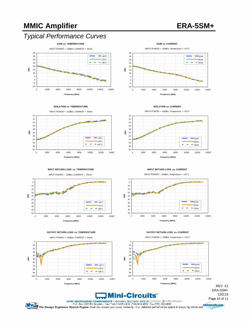
MMIC Amplifier ERA-5SM+Typical Performance Curves
GAIN vs. TEMPERATURE
-10-505
1015
2025303540
0 2000 4000 6000 8000 10000 12000 14000
Frequency (MHz)
(dB
)
-45°C+25°C+85°C
INPUT POWER = -20dBm, CURRENT = 65mA
GAIN vs. CURRENT
-10
-5
0
5
10
15
20
25
30
35
40
0 2000 4000 6000 8000 10000 12000 14000
Frequency (MHz)
(dB
)
52mA65mA78mA
INPUT POWER = -20dBm, Temperature = +25°C
ISOLATION vs. TEMPERATURE
10
12
14
16
18
20
22
24
26
28
300 2000 4000 6000 8000 10000 12000 14000
Frequency (MHz)
(dB
)
-45°C+25°C+85°C
INPUT POWER = -20dBm, CURRENT = 65mA
ISOLATION vs. CURRENT
10
12
14
16
18
20
22
24
26
28
300 2000 4000 6000 8000 10000 12000 14000
Frequency (MHz)
(dB
)
52mA65mA78mA
INPUT POWER = -20dBm, Temperature = +25°C
INPUT RETURN LOSS vs. TEMPERATURE
0
5
10
15
20
25
30
35
40
45
500 2000 4000 6000 8000 10000 12000 14000
Frequency (MHz)
(dB
)
-45°C+25°C+85°C
INPUT POWER = -20dBm, CURRENT = 65mA
INPUT RETURN LOSS vs. CURRENT
0
5
10
15
20
25
30
35
40
45
500 2000 4000 6000 8000 10000 12000 14000
Frequency (MHz)
(dB
)
52mA65mA78mA
INPUT POWER = -20dBm, Temperature = +25°C
OUTPUT RETURN LOSS vs. TEMPERATURE
0
10
20
30
40
50
60
70
80
90
1000 2000 4000 6000 8000 10000 12000 14000
Frequency (MHz)
(dB
)
-45°C+25°C+85°C
INPUT POWER = -20dBm, CURRENT = 65mA
OUTPUT RETURN LOSS vs. CURRENT
0
10
20
30
40
50
60
70
80
90
1000 2000 4000 6000 8000 10000 12000 14000
Frequency (MHz)
(dB
)
52mA65mA78mA
INPUT POWER = -20dBm, Temperature = +25°C
REV. X1ERA-5SM+
120119Page 10 of 11

MMIC Amplifier ERA-5SM+Typical Performance Curves
OUTPUT IP3 vs. TEMPERATURE
20
22
24
26
28
30
32
34
36
38
40
0 500 1000 1500 2000 2500 3000 3500 4000
Frequency (MHz)
(dB
m)
-45°C+25°C+85°C
INPUT POWER = -20dBm, CURRENT = 65mA
OUTPUT IP3 vs. CURRENT
20
22
24
26
28
30
32
34
36
38
40
0 500 1000 1500 2000 2500 3000 3500 4000
Frequency (MHz)
(dB
m)
52mA65mA78mA
INPUT POWER = -20dBm, Temperature = +25°C
OUTPUT POWER at 1dB Compression vs. TEMPERATURE
10
12
14
16
1820
22
24
26
28
30
0 500 1000 1500 2000 2500 3000 3500 4000
Frequency (MHz)
(dB
m)
-45°C+25°C+85°C
CURRENT = 65mA
OUTPUT POWER at 1dB Compression vs. CURRENT
10
12
14
16
18
20
22
24
26
28
30
0 500 1000 1500 2000 2500 3000 3500 4000
Frequency (MHz)
(dB
m)
52mA65mA78mA
Temperature = +25°C
Noise Figure vs. TEMPERATURE
0
1
2
3
4
5
6
7
8
9
10
0 500 1000 1500 2000 2500 3000 3500 4000
Frequency (MHz)
(dB
)
-45°C+25°C+85°C
CURRENT = 65mA
Noise Figure vs. CURRENT
2.0
2.2
2.4
2.6
2.8
3.0
3.2
3.4
3.6
3.8
4.0
0 500 1000 1500 2000 2500 3000 3500 4000
Frequency (MHz)
(dB
)
52mA65mA78mA
Temperature = +25°C
REV. X1ERA-5SM+
120119Page 11 of 11

MMIC Amplifier ERA-5SM+Typical Performance Curves
GAIN vs. TEMPERATURE
-10-505
1015
2025303540
0 2000 4000 6000 8000 10000 12000 14000
Frequency (MHz)
(dB
)
-45°C+25°C+85°C
INPUT POWER = -20dBm, CURRENT = 65mA
GAIN vs. CURRENT
-10
-5
0
5
10
15
20
25
30
35
40
0 2000 4000 6000 8000 10000 12000 14000
Frequency (MHz)
(dB
)
52mA65mA78mA
INPUT POWER = -20dBm, Temperature = +25°C
ISOLATION vs. TEMPERATURE
10
12
14
16
18
20
22
24
26
28
300 2000 4000 6000 8000 10000 12000 14000
Frequency (MHz)
(dB
)
-45°C+25°C+85°C
INPUT POWER = -20dBm, CURRENT = 65mA
ISOLATION vs. CURRENT
10
12
14
16
18
20
22
24
26
28
300 2000 4000 6000 8000 10000 12000 14000
Frequency (MHz)
(dB
)
52mA65mA78mA
INPUT POWER = -20dBm, Temperature = +25°C
INPUT RETURN LOSS vs. TEMPERATURE
0
5
10
15
20
25
30
35
40
45
500 2000 4000 6000 8000 10000 12000 14000
Frequency (MHz)
(dB
)
-45°C+25°C+85°C
INPUT POWER = -20dBm, CURRENT = 65mA
INPUT RETURN LOSS vs. CURRENT
0
5
10
15
20
25
30
35
40
45
500 2000 4000 6000 8000 10000 12000 14000
Frequency (MHz)
(dB
)
52mA65mA78mA
INPUT POWER = -20dBm, Temperature = +25°C
OUTPUT RETURN LOSS vs. TEMPERATURE
0
10
20
30
40
50
60
70
80
90
1000 2000 4000 6000 8000 10000 12000 14000
Frequency (MHz)
(dB
)
-45°C+25°C+85°C
INPUT POWER = -20dBm, CURRENT = 65mA
OUTPUT RETURN LOSS vs. CURRENT
0
10
20
30
40
50
60
70
80
90
1000 2000 4000 6000 8000 10000 12000 14000
Frequency (MHz)
(dB
)
52mA65mA78mA
INPUT POWER = -20dBm, Temperature = +25°C
REV. X1ERA-5SM+
120119Page 1 of 2

MMIC Amplifier ERA-5SM+Typical Performance Curves
OUTPUT IP3 vs. TEMPERATURE
20
22
24
26
28
30
32
34
36
38
40
0 500 1000 1500 2000 2500 3000 3500 4000
Frequency (MHz)
(dB
m)
-45°C+25°C+85°C
INPUT POWER = -20dBm, CURRENT = 65mA
OUTPUT IP3 vs. CURRENT
20
22
24
26
28
30
32
34
36
38
40
0 500 1000 1500 2000 2500 3000 3500 4000
Frequency (MHz)
(dB
m)
52mA65mA78mA
INPUT POWER = -20dBm, Temperature = +25°C
OUTPUT POWER at 1dB Compression vs. TEMPERATURE
10
12
14
16
1820
22
24
26
28
30
0 500 1000 1500 2000 2500 3000 3500 4000
Frequency (MHz)
(dB
m)
-45°C+25°C+85°C
CURRENT = 65mA
OUTPUT POWER at 1dB Compression vs. CURRENT
10
12
14
16
18
20
22
24
26
28
30
0 500 1000 1500 2000 2500 3000 3500 4000
Frequency (MHz)
(dB
m)
52mA65mA78mA
Temperature = +25°C
Noise Figure vs. TEMPERATURE
0
1
2
3
4
5
6
7
8
9
10
0 500 1000 1500 2000 2500 3000 3500 4000
Frequency (MHz)
(dB
)
-45°C+25°C+85°C
CURRENT = 65mA
Noise Figure vs. CURRENT
2.0
2.2
2.4
2.6
2.8
3.0
3.2
3.4
3.6
3.8
4.0
0 500 1000 1500 2000 2500 3000 3500 4000
Frequency (MHz)
(dB
)
52mA65mA78mA
Temperature = +25°C
REV. X1ERA-5SM+
120119Page 2 of 2

WW107 Rev.: H (10/04/21) ECO-009699 File: WW107.doc Sheet 1 of 1 This document and its contents are the property of Mini-Circuits.
Case Style WW
CASE# A B C D E F G H J K L M N P Q WT.
GRAMS
WW107 .012
(0.30) .10
(2.54) .020
(0.51) .092
(2.34) .085 (2.16)
.060 (1.52)
.007 (0.18)
.026 (0.66)
.235 (5.97)
.118 (3.00)
.235 (5.97)
.118 (3.00)
.072 (1.83)
.040 (1.02)
.020 (0.51)
.015
Dimensions are in inches (mm). Tolerances: 2 Pl. + .03; 3 Pl. + .015 Notes: 1. Case material: Plastic. 2. Termination finish: For RoHS Case Styles: Matte tin Plate.
For RoHS-5 Case Styles: Tin-Lead plate. 3. RF input termination (1) identified by one or both of the following at factory option:
(a) diagonally cut termination, which may be 45° (ref) in either direction; (b) orientation mark on the case. Model dash number is identified by color dot or alphanumeric code on
case. See specification data sheet.
PCB Land Pattern
Suggested Layout, Tolerance to be within .002
Outline Dimensions
WW107
98-TR-F4 Rev.: C (07/16/12) M138036 File: 98-TR-F4.doc Sheet 1 of 1 This document and its contents are the property of Mini-Circuits.
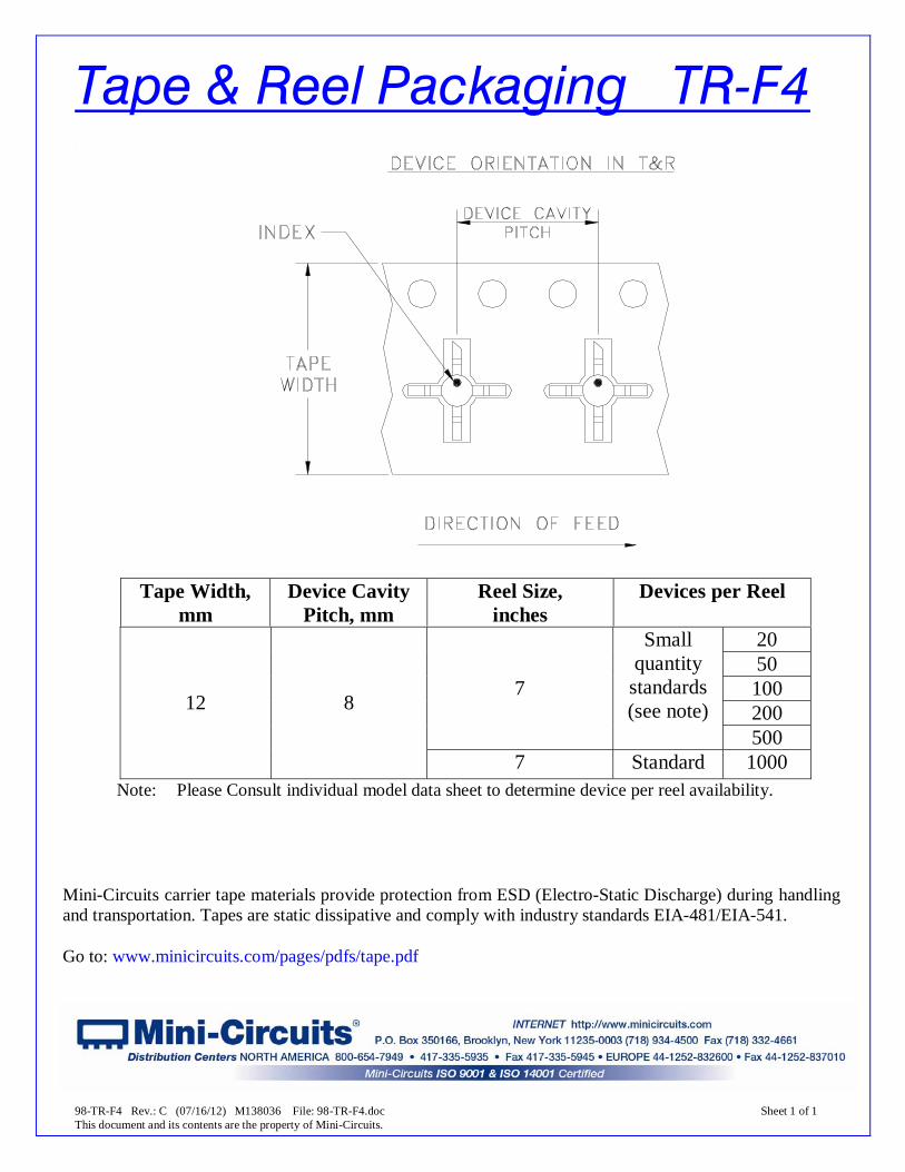
Tape & Reel Packaging TR-F4
Tape Width,
mm Device Cavity
Pitch, mm Reel Size,
inches Devices per Reel
20 50 100 200
7
Small quantity
standards (see note)
500
12 8
7 Standard 1000 Note: Please Consult individual model data sheet to determine device per reel availability.
Mini-Circuits carrier tape materials provide protection from ESD (Electro-Static Discharge) during handling and transportation. Tapes are static dissipative and comply with industry standards EIA-481/EIA-541. Go to: www.minicircuits.com/pages/pdfs/tape.pdf


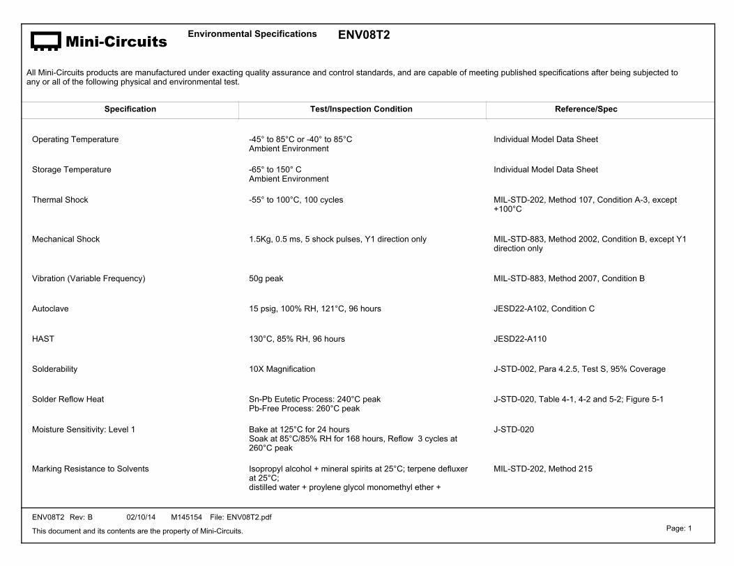
Mini-Circuits Environmental Specifications
All Mini-Circuits products are manufactured under exacting quality assurance and control standards, and are capable of meeting published specifications after being subjected to any or all of the following physical and environmental test.
Specification Test/Inspection Condition Reference/Spec
ENV08T2
Operating Temperature -45° to 85°C or -40° to 85°CAmbient Environment
Individual Model Data Sheet
Storage Temperature -65° to 150° CAmbient Environment
Individual Model Data Sheet
Thermal Shock -55° to 100°C, 100 cycles MIL-STD-202, Method 107, Condition A-3, except +100°C
Mechanical Shock 1.5Kg, 0.5 ms, 5 shock pulses, Y1 direction only MIL-STD-883, Method 2002, Condition B, except Y1 direction only
Vibration (Variable Frequency) 50g peak MIL-STD-883, Method 2007, Condition B
Autoclave 15 psig, 100% RH, 121°C, 96 hours JESD22-A102, Condition C
HAST 130°C, 85% RH, 96 hours JESD22-A110
Solderability 10X Magnification J-STD-002, Para 4.2.5, Test S, 95% Coverage
Solder Reflow Heat Sn-Pb Eutetic Process: 240°C peakPb-Free Process: 260°C peak
J-STD-020, Table 4-1, 4-2 and 5-2; Figure 5-1
Moisture Sensitivity: Level 1 Bake at 125°C for 24 hoursSoak at 85°C/85% RH for 168 hours, Reflow 3 cycles at 260°C peak
J-STD-020
Marking Resistance to Solvents Isopropyl alcohol + mineral spirits at 25°C; terpene defluxer at 25°C;distilled water + proylene glycol monomethyl ether +
MIL-STD-202, Method 215
This document and its contents are the property of Mini-Circuits.
Rev:ENV08T2 B 02/10/14 File:M145154 ENV08T2.pdfPage: 1

Mini-Circuits Environmental Specifications
All Mini-Circuits products are manufactured under exacting quality assurance and control standards, and are capable of meeting published specifications after being subjected to any or all of the following physical and environmental test.
Specification Test/Inspection Condition Reference/Spec
ENV08T2
monoethanolamine at 63°C to 70°C
This document and its contents are the property of Mini-Circuits.
Rev:ENV08T2 B 02/10/14 File:M145154 ENV08T2.pdfPage: 2
Related Documents