Surface Hardening and Microstructural Features of Chromium-Molybdenum Steel via Two-Stage Gas Nitriding with a Short Isothermal Time in Stage One Masaki Sumida National Institute of Advanced Industrial Science and Technology, Advanced Manufacturing Research Institute, Tsukuba 305-8564, Japan In this report, the surface properties and microstructure of chromium-molybdenum steel samples prepared by two-stage gas nitriding with a short isothermal time in stage one are compared with those prepared by one-stage gas nitriding. Two-stage gas nitriding was performed with a short isothermal time in stage one followed by a second stage with lowered NH 3 partial pressure, while one-stage gas nitriding was performed under conventional conditions. The variation in microstructure, compound layer thickness (CL), nitrided case depth (d) and surface hardness (HVs) was clarified. In one-stage gas nitriding, the CL, d and HVs increase with increasing isothermal time. In contrast, in two-stage gas nitriding, the CL decreases with isothermal time in the second stage, and surface microstructure observations show partial dissipation of the compound layer. The d and HVs increase at a lower rate of increase than the values observed in one-stage gas nitriding. However, when the second stage temperature was increased in two-stage gas nitriding, the CL decreases and partially dissipates in a shorter time, and d increases at a faster rate than those observed for one-stage gas nitriding. The HVs exhibits a faster rate of increase in the second stage when a higher temperature was used, but the rate is lower than that observed in one-stage gas nitriding. These experimental results are briefly discussed in relation to the microstructure. [doi:10.2320/matertrans.M2011397] (Received December 27, 2011; Accepted April 2, 2012; Published July 25, 2012) Keywords: gas nitriding, two-stage gas nitriding, compound layer thickness, nitrided case depth, surface hardness, chromium-molybdenum steel 1. Introduction In steel production, gas nitriding and related surface hardening treatments using nitrogen lead to the formation of a white layer (compound layer) of iron nitride at the surface. This layer is hard and brittle, and thus its thickness has to be strictly controlled. Under normal industrial conditions, the white layer is 10-20 μm thick and is composed principally of ¾ (Fe 2-3 N) and £A (Fe 4 N) phases. To avoid causing cracks and breakages at the surfaces of tribological components and dies of steels, it is necessary to remove this layer by grinding treatments after nitriding. The layer thickness is defined as the compound layer thickness (CL) 1) and because of its white appearance in microstructure observations it is known as the “white layer”. This layer is more corrosion resistant than the base alloy as can be observed in microstructure observations after application of an etching reagent. Because the CL significantly influences the size precision and service life of workpieces, it must be accurately controlled in gas nitriding. Two-stage gas nitriding has been reported by C. Floe. 2,3) As suggested, the technique involves two stages of nitriding. Following the first stage using conventional gas nitriding conditions, conditions of high temperature and high NH 3 dissociation percentage are used in the second stage, enabling an increase in the nitrided case depth and a decrease in the CL. 4-6) Because this technique consumes less NH 3 , the consumption of energy and resources is reduced and gas emissions are cleaner. In a typical two-stage gas nitriding process performed currently, the first stage uses conditions of T 1 = 520°C at a time t 1 = 5-10 h with a NH 3 dissociation percentage of ¤ 1;NH 3 = 15-25%, while the second stage uses conditions of T 2 = 565°C, t 2 = 5-50 h and ¤ 2;NH 3 = 75- 85%. 7) In studies of the phase equilibrium diagrams of such systems, 8-10) these conditions at the first stage are found to give a high nitriding potential, in which the ¾ phase is stable under local equilibrium conditions, and an ¾ layer and intermediate £A phase form at the surface. At the second stage, by applying a low nitriding potential through the use of a high ¤ 2;NH 3 , the ¾ layer is considered to decompose and dissipate as a result of the phase becoming unstable. The N yielded by this decomposition diffuses towards the interior and thickens the nitrided case depth while decreasing the CL. The high T 2 is thought to enhance these kinetics. To avoid simultaneous denitriding into the gas atmosphere, a certain amount of NH 3 partial pressure has to be applied during the second stage through a high ¤ 2;NH 3 . Because the denitrided regions can lead to surface cracks, appropriate second-stage conditions need to be selected to prevent the crack formation. However, using the treatment conditions described above, the CL is on the order of 10 μm after the first stage. It is predicted from model analyses that in the second stage a long t 2 is required to reduce the CL towards zero. Typically it takes several tens of hours or even hundreds of hours. 5) To maintain the diffusion of N towards the interior and to decrease the CL efficiently, some reports have described the introduction of N 2 gas, 11) and that the NH 3 gas flow is ceased 12,13) at the second stage. However, because in this case the nitriding potential becomes zero, that is, no N is supplied from the atmospheric gas, denitriding may take place. Taking these factors into account, it may be supposed that by starting the second stage after first stage conditions of a small t 1 and a thin CL, it is possible to dissipate the CL and yield a sufficient nitrided case depth by using a small t 2 . In the present research, the relationship between the microstructure and surface properties is investigated in one- stage and two-stage gas nitriding with a short isotherm applied at the first stage. The behavior of the white layer and the nitrided case depth are clarified under different conditions for chromium-molybdenum steel. Materials Transactions, Vol. 53, No. 8 (2012) pp. 1468 to 1474 © 2012 The Japan Institute of Metals

Welcome message from author
This document is posted to help you gain knowledge. Please leave a comment to let me know what you think about it! Share it to your friends and learn new things together.
Transcript
Surface Hardening and Microstructural Featuresof Chromium-Molybdenum Steel via Two-Stage Gas Nitridingwith a Short Isothermal Time in Stage One
Masaki Sumida
National Institute of Advanced Industrial Science and Technology, Advanced Manufacturing Research Institute,Tsukuba 305-8564, Japan
In this report, the surface properties and microstructure of chromium-molybdenum steel samples prepared by two-stage gas nitriding with ashort isothermal time in stage one are compared with those prepared by one-stage gas nitriding. Two-stage gas nitriding was performed with ashort isothermal time in stage one followed by a second stage with lowered NH3 partial pressure, while one-stage gas nitriding was performedunder conventional conditions. The variation in microstructure, compound layer thickness (CL), nitrided case depth (d) and surface hardness(HVs) was clarified. In one-stage gas nitriding, the CL, d and HVs increase with increasing isothermal time. In contrast, in two-stage gasnitriding, the CL decreases with isothermal time in the second stage, and surface microstructure observations show partial dissipation of thecompound layer. The d and HVs increase at a lower rate of increase than the values observed in one-stage gas nitriding. However, when thesecond stage temperature was increased in two-stage gas nitriding, the CL decreases and partially dissipates in a shorter time, and d increases at afaster rate than those observed for one-stage gas nitriding. The HVs exhibits a faster rate of increase in the second stage when a highertemperature was used, but the rate is lower than that observed in one-stage gas nitriding. These experimental results are briefly discussed inrelation to the microstructure. [doi:10.2320/matertrans.M2011397]
(Received December 27, 2011; Accepted April 2, 2012; Published July 25, 2012)
Keywords: gas nitriding, two-stage gas nitriding, compound layer thickness, nitrided case depth, surface hardness, chromium-molybdenum steel
1. Introduction
In steel production, gas nitriding and related surfacehardening treatments using nitrogen lead to the formation of awhite layer (compound layer) of iron nitride at the surface.This layer is hard and brittle, and thus its thickness has to bestrictly controlled. Under normal industrial conditions, thewhite layer is 1020 µm thick and is composed principally of¾ (Fe23N) and £A (Fe4N) phases. To avoid causing cracks andbreakages at the surfaces of tribological components and diesof steels, it is necessary to remove this layer by grindingtreatments after nitriding. The layer thickness is defined asthe compound layer thickness (CL)1) and because of its whiteappearance in microstructure observations it is known as the“white layer”. This layer is more corrosion resistant than thebase alloy as can be observed in microstructure observationsafter application of an etching reagent. Because the CLsignificantly influences the size precision and service life ofworkpieces, it must be accurately controlled in gas nitriding.
Two-stage gas nitriding has been reported by C. Floe.2,3)
As suggested, the technique involves two stages of nitriding.Following the first stage using conventional gas nitridingconditions, conditions of high temperature and high NH3
dissociation percentage are used in the second stage, enablingan increase in the nitrided case depth and a decrease in theCL.46) Because this technique consumes less NH3, theconsumption of energy and resources is reduced and gasemissions are cleaner. In a typical two-stage gas nitridingprocess performed currently, the first stage uses conditions ofT1 = 520°C at a time t1 = 510 h with a NH3 dissociationpercentage of ¤1;NH3
= 1525%, while the second stage usesconditions of T2 = 565°C, t2 = 550 h and ¤2;NH3
= 7585%.7)
In studies of the phase equilibrium diagrams of suchsystems,810) these conditions at the first stage are found to
give a high nitriding potential, in which the ¾ phase is stableunder local equilibrium conditions, and an ¾ layer andintermediate £A phase form at the surface. At the second stage,by applying a low nitriding potential through the use of ahigh ¤2;NH3
, the ¾ layer is considered to decompose anddissipate as a result of the phase becoming unstable. The Nyielded by this decomposition diffuses towards the interiorand thickens the nitrided case depth while decreasing the CL.The high T2 is thought to enhance these kinetics. To avoidsimultaneous denitriding into the gas atmosphere, a certainamount of NH3 partial pressure has to be applied during thesecond stage through a high ¤2;NH3
. Because the denitridedregions can lead to surface cracks, appropriate second-stageconditions need to be selected to prevent the crack formation.
However, using the treatment conditions described above,the CL is on the order of 10 µm after the first stage. It ispredicted from model analyses that in the second stage a longt2 is required to reduce the CL towards zero. Typically it takesseveral tens of hours or even hundreds of hours.5)
To maintain the diffusion of N towards the interior andto decrease the CL efficiently, some reports have describedthe introduction of N2 gas,11) and that the NH3 gas flow isceased12,13) at the second stage. However, because in this casethe nitriding potential becomes zero, that is, no N is suppliedfrom the atmospheric gas, denitriding may take place. Takingthese factors into account, it may be supposed that by startingthe second stage after first stage conditions of a small t1 anda thin CL, it is possible to dissipate the CL and yield asufficient nitrided case depth by using a small t2.
In the present research, the relationship between themicrostructure and surface properties is investigated in one-stage and two-stage gas nitriding with a short isothermapplied at the first stage. The behavior of the white layer andthe nitrided case depth are clarified under different conditionsfor chromium-molybdenum steel.
Materials Transactions, Vol. 53, No. 8 (2012) pp. 1468 to 1474©2012 The Japan Institute of Metals

2. Experimental
Chromium-molybdenum steel JIS-SCM435H is used forthe samples. The chemical constituents are shown in Table 1,which shows that it is equivalent to AISI-4135. Small pieces(2 © 2 © 4mm) were cut from the as-received alloy ingot andsupplied to the gas nitriding treatment soon after surfacepolishing with Emery paper (#1000 grit) and ultrasoniccleaning in ethanol. Nitriding treatment was performed in acopper tube furnace (º 8mm © 1000mm) under flowingNH3 + H2 mixed gas supplied at a total flow rate of 100cm3/min. A part of the tube was heated in the electric furnacewhile inserting the sample into the heated zone in the tubeusing a stainless holder to perform one- and two-stage gasnitriding.
In one-stage gas nitriding (Nos. A1A4), a temperature ofT1 = 520°C, and an NH3 gas partial pressure of P1;NH3
=60% were used, as shown in the heat treatment diagramin Fig. 1. At this time, the gas nitriding potential, whichindicates the nitriding ability of the gas atmosphere, isestimated as KN1 = 60795 Pa/40530 Pa3/2 = 7.5 © 10¹3
Pa¹1/2, and t1 is varied in the range of 7540min. Theseexperimental conditions are summarized in Table 2.
In two-stage gas nitriding with a short isothermal time instage 1 (small t1), the flowing gas composition ratio wasvaried at the beginning of the second stage (stage 2). Asshown in the heat treatment diagram in Fig. 2, the gasatmosphere was changed while maintaining the isothermaltemperature (Nos. B1B6). Here, conditions of t1 = 7min,T1 = 520°C, and P1;NH3
= 60% were used at the first stage(stage 1), as determined from the results of one-stage gasnitriding. Here, the gas nitriding potential, KN1 = 7.5 ©10¹3 Pa¹1/2, is identical to that of Nos. A1A4. At stage 2,conditions of T2 = 520°C and P2;NH3
= 13.3% were used andt2 was varied in the range of 13173min. Here, the gasnitriding potential is estimated as KN2 = 5.2 © 10¹4 Pa¹1/2,and the nitriding time is defined as tN = t1 + t2 (20180min)
hereinafter. These experimental conditions are summarized inTable 3.
Further, two-stage gas nitriding with a small t1 and a highT2 was performed. As shown in the heat treatment diagramin Fig. 3, the flowing gas composition ratio was varied(Nos. C1C5) and the temperature was increased to T2 =565°C at the beginning of stage 2, while maintaining thesame conditions at stage 1. The time t2 was varied in therange of 23173min, but this value includes a transition timeof 5min between T1 and T2. The gas nitriding potential atstage 2 is also KN2 = 5.2 © 10¹4 Pa¹1/2. For the samplesNos. B1B6 and Nos. C1C5, the NH3 and H2 gas flowswere set to 20 and 130 cm3/min, respectively, to give a lowNH3 gas flow.
A thermocouple (K-type) for temperature control was setat a distance of 5 cm from the sample position. Non-reactiveAr gas at a flow rate of 100 cm3/min was applied during theheating period (10°C/min). The flow of NH3 + H2 gas wasstarted simultaneously upon reaching T1. After the nitridingtime tN, the electric power output and NH3 + H2 gas flowwere set to zero and an Ar gas flow at 100 cm3/min wasstarted. The sample was then cooled to room temperature in
Table 1 Chemical constituents of as-received SCM435H alloy.
Elements C Si Mn P S Ni Cr Mo Cu
mass% 0.36 0.25 0.81 0.013 0.016 0.07 1.08 0.15 0.11
Time, t / min
Tem
pera
ture
,T
/ °C
P1,NH3: 60%
P1,H2: 40%
t1: 7 - 540min
T1: 520°C
NH
3pa
rtia
l pr
essu
re ,
PN
H3
(%)
FC
Ar:
100%Ar:
100%
Fig. 1 Heat treatment diagram and conditions for one-stage gas nitriding.
Table 2 Experimental conditions and resultant compound layer thickness(CL), nitrided case depth (d) and surface hardness (HVs) in one-stage gasnitriding.
No. A1 A2 A3 A4
Stage 1:
Temperature, T1/°C 520 520 520 520
Time, t1/min 7 15 180 540
NH3 partial pressure, P1;NH3(%) 60 60 60 60
H2 partial pressure, P1;H2(%) 40 40 40 40
Total gas flow/cm3min¹1 100 100 100 100
Gas nitriding potential, KN1/©10¹3 Pa¹1/2 7.5 7.5 7.5 7.5
Nitriding time, tN/min 7 15 180 540
Compound layer thickness CL (·)/µm 1.17 2.03 5.90 6.96
(0.40) (0.40) (1.09) (1.38)
Nitrided case depth, d/mm 0.029 0.058 0.207 0.278
Surface hardness, HVs (·)/HV 368.3 522.1 771.3 845.9
(26.9) (44.1) (66.5) (23.2)
Stage 1P1,NH3
: 60%P1,H2
: 40%t1: 7min
Stage 2P2,NH3
: 13.3%P2,H2
: 86.7%t2: 13 - 173min
T1: 520°C
FC
Ar: 100%
Ar: 100%
Time, t / min
Tem
pera
ture
,T
/ °C
NH
3pa
rtia
l pr
essu
re ,
PN
H3
(%)
Fig. 2 Heat treatment diagram and conditions for two-stage gas nitridingwith a small t1.
Surface Hardening and Microstructural Features of Chromium-Molybdenum Steel via Two-Stage Gas Nitriding 1469

the furnace. The sample taken from the furnace was cut inhalf by a cutting machine and microstructure observations ofthe cut face (2 © 2mm) after polishing were carried out usingan optical microscope. The observed face was finished bybuff polishing with a 0.1 µm diamond paste and etched with5% Nital. The CL of each sample was determined frommicrographs taken at three arbitrary sites. By measuring tenvertical lengths to the surface in each micrograph, the meanand standard deviation (·) were estimated from a total ofthirty lines.
The Vickers hardness was measured by a microhardnesstester (Akashi HV-114) and hardness profiles were measuredvertically along the cross-section surfaces by indentationsmade over 50 µm intervals. A load of 2.94N and anindentation time of 15 s were used and the nitrided casedepth (d) was determined as the distance from the surface to a
point with hardness of 300HV. The surface hardness (HVs)was determined using the same measurement conditions forfive points on the sample surface after nitriding, and the meanand standard deviation (·) were estimated.
3. Experimental Results
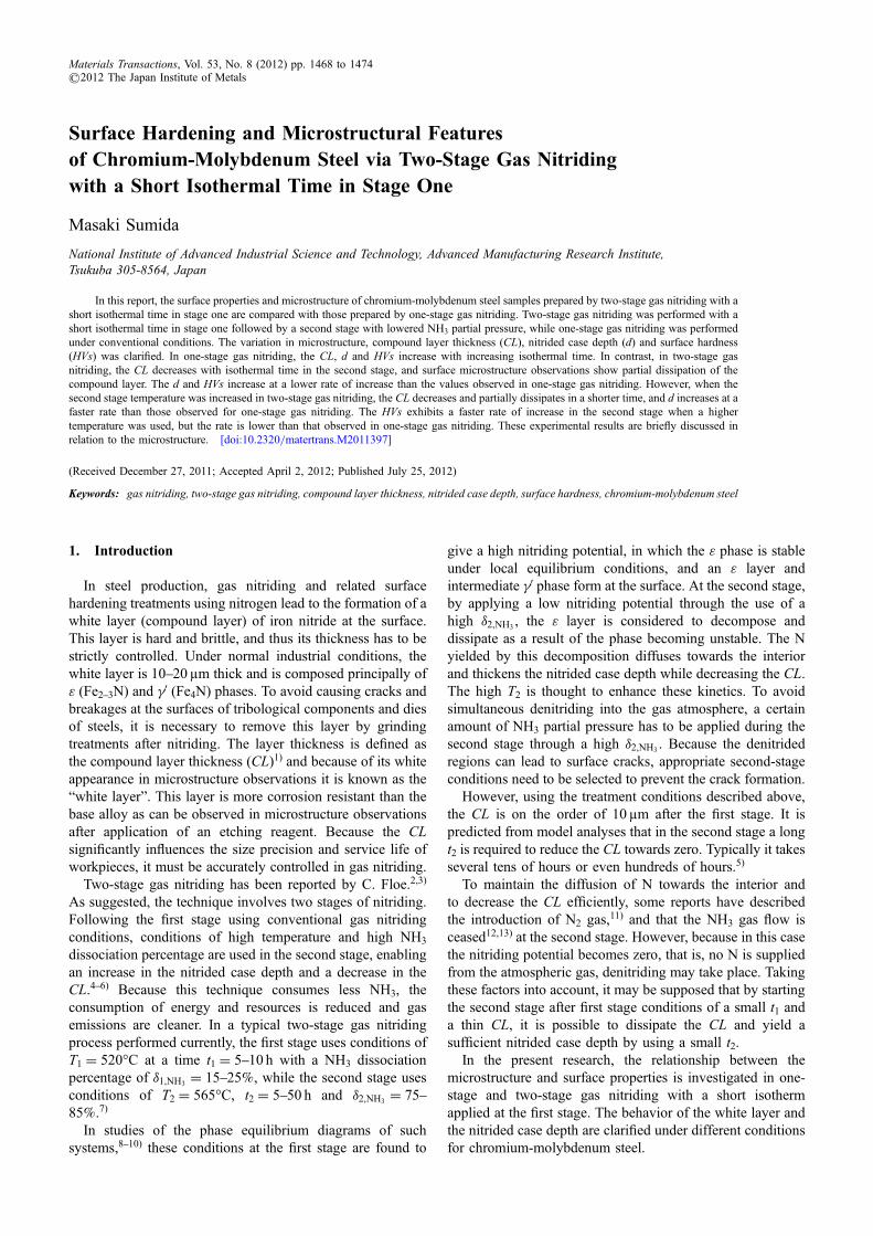
3.1 One-stage gas nitridingFigure 4 shows the optical microstructure of one-stage gas
nitrided samples prepared at t1 = 7540min (Nos. A1A4).The white layers can be observed on the sample surfaces.The lower parts exhibit the microstructure of the base alloy,with white ferrite regions and pearlite stripes apparent. InFig. 4(a), a very thin white layer can be seen after a shortisotherm at t1 = 7min. With increasing t1 the layer thickens,becoming considerably thicker at t1 = 540min (Fig. 4(d)).
The phase constituents in the white layer of alloy steelshave been investigated by several authors.1315) Ratajski14)
performed gas nitriding on an AISI-4140 alloy, usingconditions of 480°C / 8 h / KN = 20 for one-stage nitriding,and 480°C / 8 h / KN = 20 followed by 530°C / KN = 0.45for two-stage nitriding. Phase constituents in the formedwhite layer were identified by X-ray analysis. Their resultsshowed that the layer formed in one-stage gas nitridingcontains a mixture of principally ¾ (phase fraction of 86%)and £A phases. The phase constituents in the white layerstructure of Fig. 4 are assumed to be similar.
Figure 5 shows the hardness profiles measured verticallyalong the cross-section surfaces of the samples. The HVs isplotted at x = 0. From this figure, it can be seen that thecurves move upwards with increasing t1 with the d and HVsincreasing accordingly. The hardness of the core is around200HV. The CL, d and HVs of these samples are plottedagainst the square root of tN as open circles in Figs. 6, 7
Table 3 Experimental conditions and resultant compound layer thickness (CL), nitrided case depth (d) and surface hardness (HVs) in two-stage gas nitriding with a small t1 (B1B6) and with a small t1 and a high T2 (C1C5).
No. B1 B2 B3 B4 B5 B6 C1 C2 C3 C4 C5
Stage 1:
Temperature, T1/°C 520 520 520 520 520 520 520 520 520 520 520
Time, t1/min 7 7 7 7 7 7 7 7 7 7 7
NH3 partial pressure, P1;NH3(%) 60 60 60 60 60 60 60 60 60 60 60
H2 partial pressure, P1;H2(%) 40 40 40 40 40 40 40 40 40 40 40
Total gas flow/cm3min¹1 100 100 100 100 100 100 100 100 100 100 100
Gas nitriding potential, KN1/©10¹3 Pa¹1/2 7.5 7.5 7.5 7.5 7.5 7.5 7.5 7.5 7.5 7.5 7.5
Stage 2:
Temperature, T2/°C 520 520 520 520 520 520 565 565 565 565 565
Time, t2/min 13 23 53 83 113 173 23 53 83 113 173
NH3 partial pressure, P2;NH3(%) 13.3 13.3 13.3 13.3 13.3 13.3 13.3 13.3 13.3 13.3 13.3
H2 partial pressure, P2;H2(%) 86.7 86.7 86.7 86.7 86.7 86.7 86.7 86.7 86.7 86.7 86.7
Total gas flow/cm3min¹1 150 150 150 150 150 150 150 150 150 150 150
Gas nitriding potential, KN2/©10¹3 Pa¹1/2 0.52 0.52 0.52 0.52 0.52 0.52 0.52 0.52 0.52 0.52 0.52
Nitriding time, tN/min 20 30 60 90 120 180 30 60 90 120 180
Compound layer thickness, CL (·)/µm 1.83 1.46 1.61 0.92 0.70 0.73 1.00 0.87 0.49 0.68 0.83
(0.71) (1.02) (1.03) (0.86) (0.48) (0.81) (0.82) (0.92) (1.00) (0.76) (0.84)
Nitrided case depth, d/mm 0.040 0.051 0.068 0.087 0.101 0.088 0.076 0.143 0.162 0.182 0.192
Surface hardness, HVs (·)/HV 388.5 419.7 426.3 426.5 448.3 498.0 436.3 525.1 566.3 562.0 578.3
(19.9) (29.7) (30.2) (50.3) (21.5) (45.3) (23.5) (28.8) (34.9) (25.0) (35.8)
Stage 1P1,NH3
: 60%P1,H2
: 40%t1: 7min
Stage 2P2,NH3
: 13.3%P2,H2
: 86.7%t2: 23-173min
T1: 520°C T2: 565°C
5minFC
Ar: 100%
Ar: 100%
Time, t / min
Tem
pera
ture
,T
/ °C
NH
3pa
rtia
l pr
essu
re, P
NH
3(%
)
Fig. 3 Heat treatment diagram and conditions for two-stage gas nitridingwith a small t1 and a high T2.
M. Sumida1470
and 8, and are summarized in Table 2. With increasing t1, theCL, d, and HVs increase monotonically from 1.17 to 6.96 µm,from 0.029 to 0.278mm and from 368.3 to 845.9HV,respectively.
3.2 Two-stage gas nitriding with a short isothermal timein the first stage
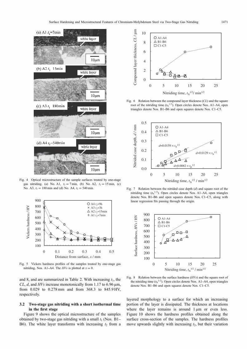
Figure 9 shows the optical microstructure of the samplesobtained by two-stage gas nitriding with a small t1 (Nos. B1B6). The white layer transforms with increasing t2 from a
layered morphology to a surface for which an increasingportion of the layer is dissipated. The thickness at locationswhere the layer remains is around 1µm or even less.Figure 10 shows the hardness profiles obtained along thesurface cross-section of the samples. The hardness profilesmove upwards slightly with increasing t2, but their variation
Fig. 4 Optical microstructure of the sample surfaces treated by one-stagegas nitriding, (a) No. A1, t1 = 7min, (b) No. A2, t1 = 15min, (c)No. A3, t1 = 180min and (d) No. A4, t1 = 540min.
100
200
300
400
500
600
700
800
900
0 0.1 0.2 0.3 0.4 0.5
A4 t1=9hA3 t1=3h A2 t1=15minA1 t1=7min
Vic
kers
har
dnes
s / H
V
Distance from surface, x / mm
Fig. 5 Vickers hardness profiles of the samples treated by one-stage gasnitriding, Nos. A1A4. The HVs is plotted at x = 0.
0
2
4
6
8
10
0 5 10 15 20 25
A1-A4B1-B6C1-C5
Nitriding time, tN1/2/ min1/2
Com
poun
d la
yer
thic
knes
s, C
L /
μm
Fig. 6 Relation between the compound layer thickness (CL) and the squareroot of the nitriding time (tN1/2). Open circles denote Nos. A1A4, opentriangles denote Nos. B1B6 and open squares denote Nos. C1C5.
0.0
0.1
0.2
0.3
0.4
0.5
0 5 10 15 20 25
d=0.0159 × tN1/2
d=0.0082 × tN1/2
d=0.0129 × tN1/2
A1-A4B1-B6C1-C5
Nitriding time, tN1/2 / min1/2
Nitr
ided
cas
e de
pth,
d /
mm
Fig. 7 Relation between the nitrided case depth (d) and square root of thenitriding time (tN1/2). Open circles denote Nos. A1A4, open trianglesdenote Nos. B1B6 and open squares denote Nos. C1C5, along withlinear regression fits passing through the origin.
100200300
400500600700
800900
0 5 10 15 20 25
A1-A4B1-B6C1-C5
Nitriding time, tN1/2 / min1/2
Surf
ace
hard
ness
, HV
s / H
V
Fig. 8 Relation between the surface hardness (HVs) and the square root ofthe nitriding time (tN1/2). Open circles denote Nos. A1A4, open trianglesdenote Nos. B1B6 and open squares denote Nos. C1C5.
Surface Hardening and Microstructural Features of Chromium-Molybdenum Steel via Two-Stage Gas Nitriding 1471

is relatively small. The CL, d and HVs of the samples areplotted as open triangles in Figs. 6, 7 and 8, respectively, andare summarized in Table 3. From Fig. 6, it can be seen thatthe CL of these samples roughly decreases with increasing tN.In Figs. 7 and 8, the d and HVs generally increase withincreasing tN, although d decreases slightly at tN1/2 = 13.4(tN = 180min). The d and HVs are both lower than thoseobtained in one-stage gas nitriding.
Figure 11 shows the optical microstructure of the samplesobtained by two-stage gas nitriding with a small t1 anda high T2 (Nos. C1C5). The white layer has partiallydissipated in sample No. C1 (t2 = 23min) and the region ofdissipation increases with increasing t2, becoming almostcompletely dissipated in No. C3 (t2 = 83min). The time atwhich dissipation occurs is slightly less than that observedfor Nos. B1B6. The rate of decomposition of the whitelayer is assumed to be enhanced due to the high T2.Figure 12 shows the hardness profiles measured verticallyalong the cross section surfaces of the samples. The hardnessprofiles move upwards with increasing t2, but the variationamong samples is small at t2 times above 83min. The CL,d and HVs of the samples are shown as open squaresin Figs. 6, 7 and 8, respectively, and are summarized inTable 3. From Fig. 6, it can be seen that the CL values arelower than those of Nos. A1A4, or even those of Nos. B1B6. In Figs. 7 and 8, the d and HVs increase almostmonotonically with increasing tN. In Nos. C4C5, althoughthe change in d is small (d = 0.1820.192mm overtN1/2 = 11.013.4), the values are comparable to those ofNos. A1A4 and larger than those of Nos. B1B6. The HVsvalues are lower than those of Nos. A1A4, but higher thanthose of Nos. B1B6.
Fig. 9 Optical microstructure of the sample surfaces treated by two-stagegas nitriding with a small t1. (a) No. B1, t2 = 13min, (b) No. B3,t2 = 53min, (c) No. B5, t2 = 113min and (d) No. B6, t2 = 173min.
100
200
300
400
500
600
700
800
900
0 0.1 0.2 0.3 0.4 0.5
B6 t1=7min/t2=173minB5 t1=7min/t2=113minB3 t1=7min/t2=53minB1 t1=7min/t2=13min
Vic
kers
har
dnes
s / H
V
Distance from surface, x / mm
Fig. 10 Vickers hardness profiles of the samples treated by two-stage gasnitriding with a small t1, Nos. B1, B3, B5 and B6. The HVs is plotted atx = 0.
Fig. 11 Optical microstructure of the sample surfaces treated by two-stagegas nitriding with a small t1 and a high T2. (a) No. C1, t2 = 13min,(b) No. C3, t2 = 53min, (c) No. C4, t2 = 113min and (d) No. C5,t2 = 173min.
M. Sumida1472

4. Discussion
In the one-stage gas nitriding of Nos. A1A4, a gasnitriding potential of KN1 = 7.5 © 10¹3 Pa¹1/2 (= 2.4atm¹1/2) was used. Referring to the Lehrer’s diagram8,9)
shown in Fig. 13, a brief and qualitative explanation ofthe experimental results is discussed based on the generalprinciples of gas nitriding. In the diagram, the condition at520°C is indicated by point A, in which the stable phase atthe surface is the ¾ phase and the N concentration at the ¾
surface is about 8.2%. The ¾ phase grows with increasing t1,and the CL thickens, resulting in increases in the d andHVs due to N diffusion through the ¾ layer. The conditionsfor stage 1 for Nos. B1B6 and Nos. C1C5 were set atthese values. In stage 2, the gas nitriding potential wasKN2 = 5.2 © 10¹4 Pa¹1/2 (= 0.17 atm¹1/2) and for Nos. B1B6 a temperature of T2 = 520°C was used. The stable phaseat the surface is the ¡ phase (point B) and the Nconcentration at the ¡ surface is about 0.04%. ForNos. C1C5 prepared at T2 = 565°C, the ¡ phase is also
found to be stable at the surface (point C), but the Nconcentration at the ¡ surface is about 0.07%, which is higherthan that for Nos. B1B6.
For Nos. B1B6 and Nos. C1C5 treated by two-stage gasnitriding, both the ¾ and £A phases formed at stage 1 becomeunstable at stage 2. Decomposition of these phases takesplace, and decrement and dissipation of the whitelayer progresses as seen in Fig. 6. On the one-hand,denitriding from the principal phase ¡ in the base micro-structure does not readily take place due to the N concen-tration at the ¡ surface, and the N yielded by decompositionof the ¾ and the £A phases is thought to diffuse into theinterior. However, because the N supply from the gasatmosphere to the surface is small, existing only at aconcentration of about 0.04%, the rate of increase of d issmall for Nos. B1B6.
Because Nos. C1C5 have a higher surface concentrationthan Nos. B1B6 a greater supply of N is assumed. Ndiffusion is promoted and decomposition of the white layeradvances quickly due to the high T2. In fact, the CL valuesare below 1µm for Nos. B4B5 and Nos. C1C5. These aresmaller than that of No. A1, treated under the sameconditions at stage 1, thus indicating decomposition of thewhite layer in stage 2. However, the HVs values are low inthese samples. Taking into account the results of themicrostructure observations, this is considered to be due toa decrement in the hard compound layer at the surface.The HVs values of Nos. C1C5 are larger than those ofNos. B1B6, which indicates that N diffusion in the solidwas promoted along with precipitation of nitrides of Cr, Moand other elements due to the high T2.
By regression fitting of d against tN according to aparabolic law (d = k © tN1/2), the following equations areobtained from Fig. 7.
d ¼ 1:29� 10�2 � tN1=2 for Nos: A1A4,
d ¼ 0:82� 10�2 � tN1=2 for Nos: B1B6, and
d ¼ 1:59� 10�2 � tN1=2 for Nos: C1C5
As can be seen, the k values decrease from k = 1.29 ©10¹2mm/min1/2 to k = 0.82 © 10¹2mm/min1/2 for samplesobtained from one-stage gas nitriding and two-stage gasnitriding with a small t1, respectively, showing that therate of increase of d is lower in the latter case. However,a high T2 is effective in increasing d as shown by theconstant k = 1.59 © 10¹2mm/min1/2 obtained in two-stagegas nitriding with a small t1 and a high T2.
These results show that the two-stage gas nitriding with asmall t1 is effective in controlling the CL, d and HVs. Bystarting stage 2 under the condition of a small CL afterstage 1, a surface microstructure with a partially dissipatedwhite layer and sufficiently thick nitrided case depth can beobtained. These characteristics should enable a reduction inthe process time and resulting energy consumption. Also,a reduction in the white layer may reduce the grindingtreatment required after nitriding. Further, the NH3 gas flowis by approximately 76% lower for No. B6 and No. C5 thanthat of No. A3 over tN = 180min. Although the sameamount of H2 gas is required complementarily in thesecases, the reduction in NH3 offers resource savings while alsoproviding cleaner gas emissions and reduced cost.
100
200
300
400
500
600
700
800
900
0 0.1 0.2 0.3 0.4 0.5
C5 t1=7min/t2=173minC4 t1=7min/t2=113minC3 t1=7min/t2=83minC1 t1=7min/t2=23min
Vic
kers
har
dnes
s / H
V
Distance from surface, x / mm
Fig. 12 Vickers hardness profiles of the samples treated by two-stage gasnitriding with a small t1 and a high T2, Nos. C1, C3, C4 and C5. The HVsis plotted at x = 0.
-1.5 0.031.51.41.31.21.11.0
700 400450500550600 °C
17.8
1.0
1.8
5.6
10.0
31.6
3.2
0.1
0.3
1.5
0
-0.5
-1
0.5
1
0.07
0.050.03%N
0.01
5.82
5.85
5.87%N
5.89
5.897
8.258.508.75
9.259.509.75
10.00%N
5.735.78
9.00
0.001
0.005
ε
α
Fe-N
γ '
γ
A
C
BLog
aris
mic
of
KN, l
og(K
N)
/ atm
-1/2
Temperature, T / °C
Gas nitriding potential, K
N / atm-1/2
Reciprocal temperature, 1/T × 103 / 1/K
Fig. 13 Schematic illustration of Lehrer’s diagram.8,9)
Surface Hardening and Microstructural Features of Chromium-Molybdenum Steel via Two-Stage Gas Nitriding 1473

5. Summary
One-stage gas nitriding, and two-stage gas nitridingwith a small t1 and those with a small t1 and a high T2were performed on chromium-molybdenum steel samples.Variation in the microstructure and surface properties underdifferent treatment condition was clarified.
In one-stage gas nitriding, the compound layer thickness,the nitrided case depth and surface hardness increase withisothermal time. In two-stage gas nitriding with a small t1,the compound layer thickness decreases with increasing t2and partial dissipation in the microstructure was observed.The nitrided case depth and surface hardness increase but therates of change are lower than those observed in one-stagegas nitriding.
In two-stage gas nitriding with a small t1 and a high T2,the compound layer thickness decreases with increasing t2and again partial dissipation in the microstructure wasobserved in shorter nitriding time. The nitrided case depthincreases with time, but its rate of increase is well comparableto that of one-stage gas nitriding. The surface hardness alsoincreases with time, but the rate of increase is low comparedto that of one-stage gas nitriding as a result of the white layerbeing thin.
Acknowledgement
The author acknowledges Dr. Fujiki at the TokyoMetropolitan Industrial Technology Research Institute forhis helpful discussions.
REFERENCES
1) Japan Industrial Standards: JIS G 0562, Method of measuring nitridedcase depth for iron and steel.
2) C. H. Knerr, T. C. Rose and J. H. Filkowski: Gas Nitriding, ASMHandbook Vol. 4, Heat Treating, (ASM International, 1990) pp. 387409.
3) C. F. Floe: Method of nitriding, US 2437249, (1948).4) The Japan Society for Heat Treatment (Ed.): Heat treatment technology,
(Nikkan Kogyo Shinbun Ltd., 2000) pp. 211239.5) M. Sumida: J. Jpn. Soc. Heat Treat. 51 (2011) 273282.6) M. Sumida: Mater. Trans., submitted.7) S. Kiyooka: J. Jpn. Soc. Heat Treat. 11 (1971) 281284.8) Aerospace Material Specification: Automated Gaseous Nitriding
Controlled by Nitriding Potential, AMS (2579/10A) June (2006).9) E. Lehrer: Zeitschrift für Elektrochemie 36 (1930) 383392.10) M. A. J. Somers and E. J. Mittemeijer: Metall. Mater. Trans. A 26
(1995) 5774.11) V. Zabavnkik: Metal Sci. Heat Treat. 9 (1967) 169171.12) D. P. Shashkov and A. B. Goryachev: Metal Sci. Heat Treat. 41 (1999)
235237.13) I. S. Belashova and D. P. Shashkov: Metal Sci. Heat Treat. 52 (2010)
229233.14) J. Ratajski: Surf. Coat. Tech. 203 (2009) 23002306.15) S. S. Akhtar, A. F. M. Arif, B. S. Yilbas and A. K. Sheikh: J. Mater.
Eng. Perf. 19 (2010) 347355.
M. Sumida1474
Related Documents