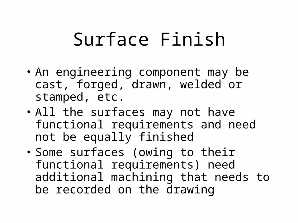
Surface Finish • An engineering component may be cast, forged, drawn, welded or stamped, etc. • All the surfaces may not have functional requirements and need not be equally finished • Some surfaces (owing to their functional requirements) need additional machining that needs to be recorded on the drawing

Surface Finish An engineering component may be cast, forged, drawn, welded or stamped, etc. All the surfaces may not have functional requirements and need.
Dec 14, 2015
Welcome message from author
This document is posted to help you gain knowledge. Please leave a comment to let me know what you think about it! Share it to your friends and learn new things together.
Transcript
Surface Finish
• An engineering component may be cast, forged, drawn, welded or stamped, etc.
• All the surfaces may not have functional requirements and need not be equally finished
• Some surfaces (owing to their functional requirements) need additional machining that needs to be recorded on the drawing


Surface RoughnessSurface RoughnessThe geometrical characteristics of a surface include,
1. Macro-deviations,
2. Surface waviness, and
3. Micro-irregularities.
The surface roughness is evaluated by the height, Rt and mean roughness index Ra of the micro-irregularities.

Surface roughness number
Represents the average departure of the surface from perfection over a prescribed sampling length, (usually selected as 0.8 mm)
Surface roughness number (Ra) is expressed in microns.
Ra = (h1+h2+-----+hn)/n
The measurements are usually made along a line, running at right angle to the general direction of tool marks on the surface.

• Actual profile, Af–It is the profile of the actual surface obtained by finishing operation.
• Reference profile, Rf–It is the profile to which the irregularities of the surface is referred to. it passes through the highest point of the actual profile.
• Datum profile, Df–It is the profile, parallel to the reference profile .it passes through the lowest point B of the actual profile

• Mean Profile, Mf
– It is that profile, within the sampling length chosen (L) such that the sum of the material-filled areas enclosed above it by the actual profile is equal to the sum of the material void area enclosed below it by the profile.
• Peak to valley height, Rt
– It is the distance from the datum profile to the reference profile.
• Mean roughness index, Ra
– It is the arithmetic mean of the absolute value of the highest hi between the actual and mean profile.
– Ra = 1/L ∫x=0 |hi| dx , where L is sampling lengthx=L

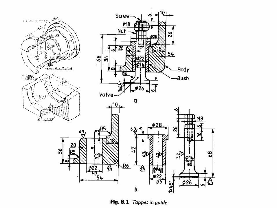
Surface Roughness expected from manufacturing processes
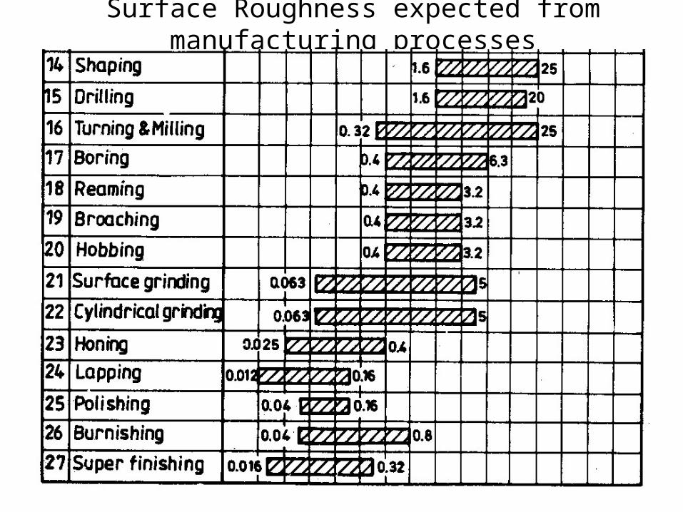
Surface Roughness expected from manufacturing processes

INDICATION OF SURFACE TEXTURE
The basic symbol consists of two legs of unequal length inclined at approximately 60’ to the line representing the considered surfaceThe symbol must be represented by thin line
If the removal of material by machining is required, a bar is added to the basic symbol,
If the removal of material is not permitted,a circle is added to the basic symbol.
When special surface characteristics have tobe indicated, a line is added to the longer arm of any of the above symbols,
Basic symbol : only be used alone when its meaning is explained by a note

Indication of Surface Roughness
The value or values defining the principal criterion of roughness are added to the symbols
a- surface roughness value
If it is necessary to impose maximumand minimum limits of the principal criterion of surface roughness, both values shall be shown
maximum limit (a1) ;minimum limit (a2).
Roughness a obtained by any production process
Roughness a obtained by removal of material by machining
Roughness a shall be obtained without removal of any material

If it is required that the required surface texture be produced by one particular production method, this method shall be indicated in plainlanguage on an extension of the longer arm of the symbol
Indication of machining allowance where it is necessary to specify the value of the machining allowance, this shall be indicated on the left of the symbols. This value shall be expressed in millimeters.

Generally to indicate the surface roughness, the symbol is used instead of value.The relation is given in following table.

Machining Symbols
This symbol may also be used in a drawing, relating to a production process , to indicate that a surface is to be left in the state ,resulting from a preceding manufacturing process,
whether this state was achieved by removal of material or otherwise

Position of the Specifications of the Surface Texture in the Symbol - The specifications Of surface texture shall be placed relative to the symbol as shown in figure.

symbol Interpretation
Parallel to the plane of projection
of the view in which the symbol is used
Perpendicular to the plane of projection of the
view in which the symbol is used
Crossed in two slant direction relative to the plane of projection of the view in
which the
symbol is used
Multidirectional
Approximately circular relative to the centre of the surface to which the symbol is applied
Approximately radial relative to the centre of the surface to which the symbol is applied

Symbols with Additional Indications.

If it is necessary to define surface texture both before and after treatment, this shall be explained in a suitable note or in accordance with figure
The direction of lay is the direction of thepredominant surface pattern, ordinarily determined by the production method employed.
If it is necessary to control the directionof lay, it is specified by a symbol added to the surface texture symbol

Ways to represent roughness

Surface finish grade is shown
Surface finish value is shown

Separate note is written

Surface finish grades specified

Riveting

Basic Dimensions

Types of rivets

for the rest of the section we study in very brief how to draw the riveting for the assembled steel sections.
Rivit Drawing


In figure (a) the representation of the rivet connecting two plates, in figure (b) shows the counter shank rivet. In figure (c) it is a plan view shows how to draw the rivets and description of some important elements in the rivet drawing.
For figure (c) the line where all the rivets should alignment to , is called the rivet line, the distance between each two rivets is called the pitch, where the distance between the first rivet and the steel section edge is half pitch and it is ≥ 6 cm. also if the line of rivets has more than three rivets , then those rivets are represented by only three rivets presented on the drawing by the plus sign.
Welding

Introduction
• It is sometimes argued that it is unnecessary to specify welds on drawings and that the welder should be relied upon to deposit a suitable weld.
• This practice can be extremely risky because– the type and size of the weld must be appropriate for
the parent material and
– service conditions of the fabrication, and
– the necessary information and data are normally available only in the design office.

Introduction
• Figure 1.1 illustrates (a) the instruction ‘weld here’ and (b–d)
• three ways to follow this instruction.

Introduction
• Figure 1.1(b) shows a single fillet weld. This weld is simple
• and therefore cheap to apply
• but could be seriously deficient in performance.

Introduction
• Figure 1.1(c) shows a double fillet weld, which takes
• longer to apply. Unless access is available to both sides of the joint,
• it will be impossible to weld it.

Introduction
• Figure 1.1(d) illustrates a T-butt/groove weld. This weld normally– requires edge preparation on a
horizontal member, and therefore is
– more complex and
– expensive.
However, it may be essential for certain service conditions.
Introduction
• It can be seen from the previous examples that major problems will arise unless welded joints are carefully specified by the design office.
• The situation is particularly critical where, for example, work is placed with a subcontractor and the instructions need to be especially precise.

The advantages of symbols
• symbolic representation can be used to cut down the time needed to complete the drawing and improve clarity.
• it may seem that the weld can simply be drawn as it will appear.

Welding Symbols
• The symbols are placed on a horizontal reference line.
• This line is attached to an arrow line which points to the location of the weld (see Fig. 2.1).
• In the ISO system there are two parallel reference lines, one solid and one dashed.
• In the AWS system a solid reference line is used.

Welding Symbols
• Figure 3.1(a) illustrates a single-V butt/groove weld, which is the commonest form of edge preparation for this type of weld.

Welding Symbols
• Figure 3.1(b) shows a square butt/groove weld. This weld will be limited to a maximum section thickness depending on the welding process used.

Welding Symbols
• Figure 3.1(c) shows a single bevel butt/groove weld. This edge preparation is generally used when it is only possible to prepare one edge of adjoining sections.

Welding Symbols
• Figure 3.1(d) illustrates a single-U butt/groove weld, which is used to restrict the quantity of weld metal required in sections greater than 12mm thick.

Welding Symbols
• Figure 3.1(e) shows a single-J butt/groove weld. This weld is used to restrict the quantity of weld metal required in sections greater than 16 mm thick when it is only possible to prepare one edge of adjoining sections.

Welding Symbols
• Figure 3.1(f) illustrates a butt weld between plates with raised edges (ISO) or edge weld on a flanged groove joint (AWS).

Welding Symbols
• Figure 4.1(a) illustrates a fillet weld. Unless otherwise indicated, the leg lengths are normally equal.

Welding Symbols
• Figure 4.1(b) shows an edge weld.

Welding Symbols
• Figure 4.1(c) shows a backing run or weld.
Welding Symbols
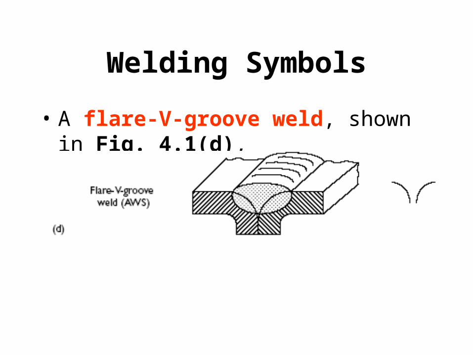
• A flare-V-groove weld, shown in Fig. 4.1(d),

Welding Symbols
• A flare-bevel-groove weld, shown in Fig. 4.1(e),

Welding Symbols
• Figure 4.1(f) shows a plug or slot weld, which is a circular or elongated hole completely filled with weld metal.

Welding Symbols
• Figure 5.1(a) shows spot welds.– resistance spot weld requiring access from both
sides.– an arc spot weld made from one side of the
joint.

Welding Symbols
• Figure 5.1(b) illustrates seam welds.– a resistance seam weld requiring access from
both sides of the joint.– an arc seam weld made from one side of the
joint.
Welding Symbols
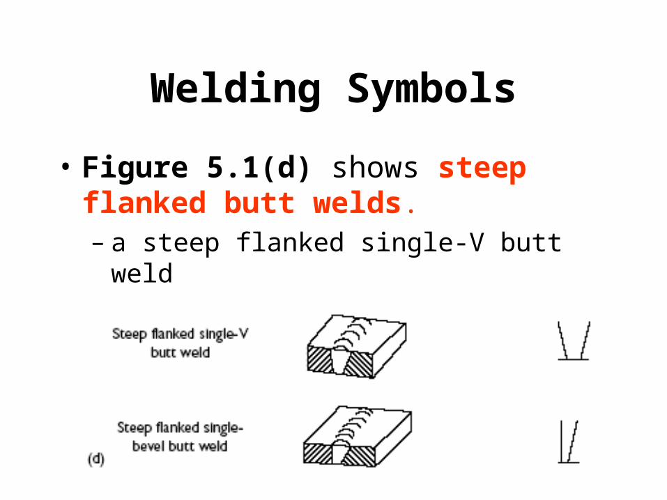
• Figure 5.1(d) shows steep flanked butt welds.– a steep flanked single-V butt weld– steep flanked single-bevel butt weld.

Welding Symbols
• Figure 5.1(c) indicates surfacing. In this symbol, the arrow line points to the surface to be coated with weld metal.

Location of symbols
• Butt/groove welds– Figure 6.1 (a–c) shows the location of
butt/groove welding symbols.
single-V butt weld
a single-bevel butt/groove weld

Location of symbols
• Fillet welds
a T-joint with a single fillet weld.
a cruciform joint.
a double fillet weld on the left of the section and a single fillet weld on the right-hand side.
Related Documents