Surface Based Wireless Power Transmission and Bidirectional Communication for Autonomous Robot Swarms Robot Swarms Travis Deyle Department of Electrical and Computer Engineering Georgia Institute of Technology ICRA 2008 Matt Reynolds Department of Electrical and Computer Engineering Duke University

Welcome message from author
This document is posted to help you gain knowledge. Please leave a comment to let me know what you think about it! Share it to your friends and learn new things together.
Transcript
Surface Based Wireless Power Transmission and Bidirectional
Communication for AutonomousRobot SwarmsRobot Swarms
Travis DeyleDepartment of Electrical and
Computer Engineering
Georgia Institute of Technology
ICRA 2008
Matt ReynoldsDepartment of Electrical and
Computer Engineering
Duke University
Overview
• The Swarm Power Problem
• Related Power Distribution Approaches
• Other Wireless Power Systems
• Proposed Power Surface Design• Proposed Power Surface Design
• Proposed Power Surface Characterization
• Conclusions

The ProblemPowering a Swarm of Robots
• Different activity levels = different power consumption
• Primary cell batteries are environmentally unfriendly
• How to maintain rechargeable batteries?
Solution: Get rid of batteries. Provide continuous
Image Credit: Caprari, EPFL SwitzerlandImage Credit: Axelrod, Georgia Tech Image Credit: McLurkin, MIT
Solution: Get rid of batteries. Provide continuous
wireless power to the swarm from its operating surface.

Potential Solutions
• Onboard Power:– Batteries
• Exchange Behaviors
• Docking Behaviors
– Alternative Sources• Hydrocarbon Fuels• Hydrocarbon Fuels
• Fuel Cells
• Biomass Fuels
• Offboard Power– Tethers
– Solar, Fields, KineticImage Credit: Caprari, EPFL Switzerland
Image Credit: Roomba from iRobot.com

Proposed SolutionWireless, battery-less power
(Robots are RFID tags with wheels & sensors)
Ampere’s Law (coil):Ampere’s Law (coil):
Faraday’s Law:

Related Work
Other Inductive Wireless Power Systems
Image Credit: Gao, Fraunhofer IBMT Image Credit: Sekitani et al, University of Tokyo
Multiple magnetic induction coils• Mechanically complex• Complex control scheme• Can provide localization info• Not easily tile-able
Multiple magnetic induction coils• Mechanically complex• MEMS and organic FETs• Complex control scheme• Can provide localization info• Tile-able

Related Work
Nano-robots powered by fields
NIST Image Credit: Craig McGray
• Surface fields cause actuation of nano-actuator• No logic or memory in the robot• Better considered “distributed actuator”

System Design
• 112KHz operating frequency• Single resonant transmitter coil in power surface• Non-resonant receiving coil on each robot• Magnetic flux coupling between transmitting and receiving coils• Surface to robot coupling virtually unaffected by number of robots• Mechanically and electrically simple • Supports bidirectional communication• Does not support localization

Resonance ConsideredAdvantage of Resonant Coils:
High Q increases circulating current in transmitting coil for given drive voltage- yields higher induced voltage in robot
Disadvantages of Resonant Coils:
High Q coils present manufacturing problems
Coupled resonant coils interact and de-tune each other
High Q resonances limit available bandwidth for communication
Tradeoff:
Use resonant transmitting coil under surface
Robots use non-resonant receiving coils
Robots interact with surface resonance, but not each other
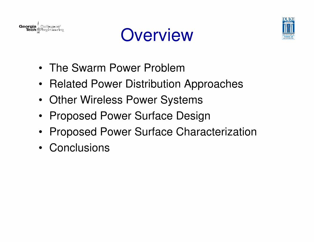
Power Surface Design
PrimaryC
Schematic Underside of Prototype
(0.6m x 0.6m)
Resonant
Secondary
L=740uHC=2.7nFF=112KHz

Robot Power Design
Logic Power
High Priority
Motor Power
Lower Priority
Schematic
Communications &
Power Conditioning
Board

Robot Prototype
Line-Following Application
PIC microcontrollerESCAP
DC gearmotors
IR line sensor array
Coil
IR Comm.

Communication
Surface-to-Robot
• 100% AM modulation
• Data rate 800bps, limited by coil Q of 125

Communication
Surface Field
Amplitude-Modulated
Surface-to-Robot at 800 bpsCoil resonance limitsrise time / data rate
Amplitude-Modulated
Robot RX Data
Robot Filtered RX

Communication
Robot-to-Surface
• Load modulation by FET switch
• Data rate 20Kbps, 1% modulation depth

Communication
Robot TX Data
Robot-to-Surface at 20 kbps
Surface DEMOD input
Surface DEMOD output

Power Density
Measured Power (Watts) into simulated robot
load (80 Ω) at various heights above surface
0 cm (on surface) 5 cm above surface
> 4.1mW/cm2 average

Power Density
Measured Power (Watts) into simulated robot
load (80 Ω) at various heights above surface
10 cm above surface 15 cm above surface
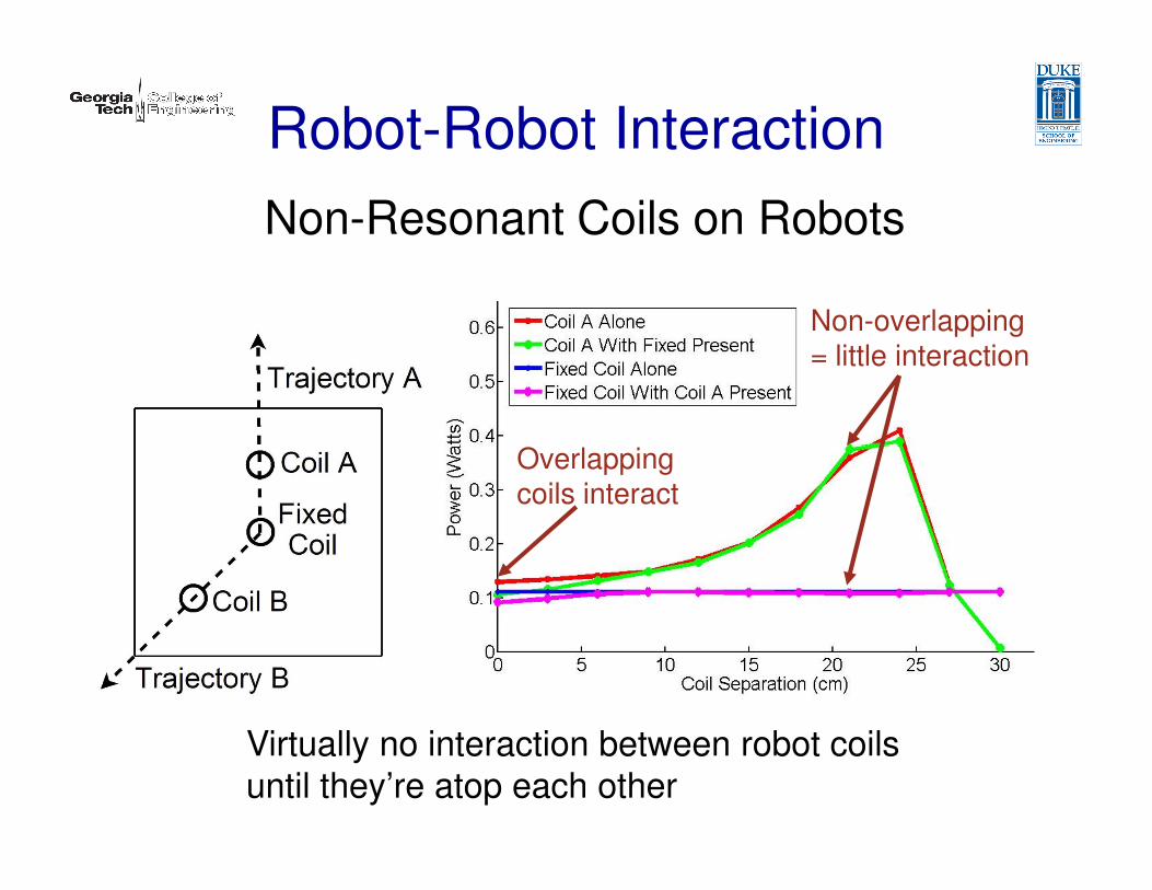
Robot-Robot Interaction
Non-Resonant Coils on Robots
Overlapping
Non-overlapping= little interaction
Virtually no interaction between robot coils
until they’re atop each other
Overlapping coils interact

System Efficiency
ηsystem ≈n ⋅ 200mW
12W+ n ⋅ 200mW ⋅ ηcoupling
Small when robot coils are small compared to surface
• Surface quiescent draw is 12W
to overcome losses in transmitting coil.
• Each robot recovers ~200mW
• Efficiency increases with # of robots

Summary
Benefits:
– Simple, Low Cost Construction
– Persistent Power to Large Number of Robots
– Bidirectional Communication
– Enabling Technology for Swarm Research
Future Work:
– Characterize Efficiency with Larger Number of Robots
– Improve Communication Bandwidth
– Develop Tiling Scheme
– Web Community for Interested Researchers

Questions?
Travis Deyle
Georgia Institute of Tech.
Matt Reynolds
Duke University
Related Documents