Surefire INSTALLATION MANUAL bright new energy world tomorrow’s energy today

Surefire GOVNA Three Phase Voltage MANUAL Optimiser · GOVNA Three Phase Voltage Optimiser bright new energy world tomorrow’s energy today. E: [email protected] Contact us direct
Jan 12, 2020
Welcome message from author
This document is posted to help you gain knowledge. Please leave a comment to let me know what you think about it! Share it to your friends and learn new things together.
Transcript

Surefire INSTALLATION MANUAL
GOVNA Three Phase Voltage Optimiser
bright new energy worldtomorrow’s energy today

E: [email protected] Contact us direct on 08006891768
INSTALLATION MANUAL
Packing ListOpen the outer carton and check all parts listed below are enclosed and undamaged. If any parts are missing or damaged please contact bnew.
A BOILER MANAGER INSTALLATION TEST SET may also be used to speed up test of the installation.
1 x User Manual 1 x 3-way 5A plastic terminal block
2 x pipe sensors with 1.5 metre cables 5 x Cable ties
3 x Cable grommets 3 x box hole blanks
2 x No.12 c/s wood screws 2 x Red plastic rawlplugs
IntroductionThe Boiler Manager works in conjunction with the boiler thermostat to control water heat-ing by the boiler. It senses temperature in both flow and return pipes with heat sensors placed in strategic positions on the pipes and uses the information to switch the boiler firing mechanism. The Boiler Manager may not be used as a replacement thermostat and must always be installed in series with the existing boiler thermostat. The Boiler Manager is not suitable for use with
• Systems where an economising controller is already in place
• A ‘single pipe’ system
• Oil fired burners
• Other non-instant ignition burners that require safety-specific control systems.
Installation must be performed by qualified personnel in accordance with local regulations. To carry out any works on Gas, Water or Electrical services the installer must be qualified to the appropriate standards as governed by HSE. A CORGI registered installer must inspect a gas boiler and confirm that it is safe before any modifications are carried out. The CORGI registered installer must certify that the modifications do not interfere with the normal safe operation of the boiler when the work is completed.
bright new energy worldtomorrow’s energy today

2. WIRING THE BOILER MANAGER
Before attempting any wiring work, ensure the electrical supply is isolated.
2.1 Connect the Power WiresThe Boiler Manager must be connected to a +24V supply to power the unit. This source must be live whilst the timer/programmer is on for either central heating or hot water, regardless of roomstat, boilerstat & cylinderstat activity. Prepare the wire ends of the cable as shown in Figure 2 and connect to the Boiler Manager terminals marked +24V, 0V. ignor the E connection, feeding the cable through the LH hole in the back box (see Figure 1).
FIGURE 2: WIRE PREPARATIONLH hole in the back box (see Figure 1).
2.2 Connect the Output WiresThe Boiler Manager output is a set of volt-free contacts. These must be connected to the exist-ing system so their operation mimics the boilerstat. i.e. When switched ‘off’, they too must turn off the solenoid valve. Three types of system are most common.
- If the existing control system has a power connection directly from the timer/programmer to the gas valve/boilerstat inside the boiler cabinet and nothing else once in the cabinet, the Boiler Manager can be installed ‘in-line’. See the wiring diagram in Figure 3.
- If the boiler is not powered directly from the timer or has additional equipment inside the cabinet, the Boiler Manager output contacts must be connected to the solenoid valve feed, on the “switched +24V” side. See the wiring diagram in Figure 4. This will in the majority of cases mean the modification of the internal boiler wiring.
- In fault-sensing systems with intelligent control boards, the Boiler Manager output contacts must be connected to a feed or control input on the board that turns off the gas valve whilst the switch is open. See the wiring diagram in Figure 5. Refer to the manufacturer’s instructions for connection identification on the control unit.
Connect the other end of the output cable to the Boiler Manager terminals marked ‘COM’ and ‘ON’, passing the cable through the 5th hole in the back box (see Figure 1).
E: [email protected] Contact us direct on 08006891768
bright new energy worldtomorrow’s energy today
B3 063Three Phase Voltage Optimiser
WIRING THE BOILER MANAGER
!
5mm# !
15m# !

Maximum switching load is 5A resistive (2A inductive). Contact suppression is necessary with highly inductive loads.
3. System TestTest can be quickly performed with a simulated input connected in place of the sensors. Reconnect the spade terminals to the BYPASS switch. With the switch set to the ’RUN’ position, connect the ‘BOILER MANAGER INSTALLATION TEST BOX’ to the system, following the instructions supplied. This tests power and output cable wiring and unit functionality. Vary the boilerstat whilst the system is running to make sure it too can still turn off the boiler.
Note: The Boiler Manager can only inhibit the boiler from firing and cannot switch the boiler on when other conditions prevent it. e.g. If roomstat & cylinderstat are not calling for heat, or the water temperature is already up to the boilerstat setting.
WARNING! Isolate power again before opening the case!
4. SENSOR CONNECTIONAttach a temperature sensor tightly to each of the flow and return pipes using the cable ties provided (2 per sensor). Ensure good thermal contact with the pipe. Connect the FLOW sensor to terminals marked CHFLOW and the RETURN sensor to terminals RETURN, passing both leads through the third hole in the back box. Leave the HWFLOW terminals unconnected. Fasten a tie-wrap around the pair of cables inside the box, 3cm from the terminal block to prevent them slipping out through the cable gland.
5. REASSEMBLYReplace the fascia and the four retaining screws. Gently retrieve any slack or wound cable from the inside of the case back through the open cable gland holes. Install cable glands and blank grommets into the appropriate knock outs within the back box, feeding about 10mm of cable back into the case with each cable clamp. Turn on power and ensure operation is as predicted by the user manual.
INSTALLATION NOTE (NON-COMBINATION BOILERS):Install as combi boilers but attach the 3rd sensor to the HW flow pipe and connect to the ’HWFLOW’ terminals, also through the 3rd hole in case.
E: [email protected] Contact us direct on 08006891768
bright new energy worldtomorrow’s energy today
WIRING THE BOILER MANAGER
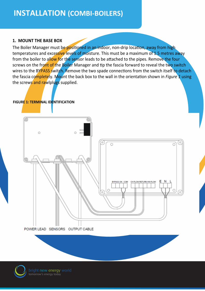
1. MOUNT THE BASE BOXThe Boiler Manager must be positioned in an indoor, non-drip location, away from high temperatures and excessive levels of moisture. This must be a maximum of 1.5 metres away from the boiler to allow for the sensor leads to be attached to the pipes. Remove the four screws on the front of the Boiler Manager and tip the fascia forward to reveal the two switch wires to the BYPASS switch. Remove the two spade connections from the switch itself to detach the fascia completely. Mount the back box to the wall in the orientation shown in Figure 1 using the screws and rawlplugs supplied.
E: [email protected] Contact us direct on 08006891768
FIGURE 1: TERMINAL IDENTIFICATION
bright new energy worldtomorrow’s energy today
B3 063Three Phase Voltage Optimiser
INSTALLATION (COMBI-BOILERS)

E: [email protected] Contact us direct on 08006891768
FIGURE 3: WIRING DIAGRAM (inline configuration)
FIGURE 4: WIRING DIAGRAM (switched live to valve configuration)
FIGURE 5: WIRING DIAGRAM (intelligent control board system)
!
bright new energy worldtomorrow’s energy today
B3 063Three Phase Voltage Optimiser
WIRING THE BOILER MANAGER

Safety Warnings
• When disposing of this product, do so in accordance with your local waste disposal regulations.
This product is expected to have a long service life. At the end of service life this product should be recycled according to the European Directive on Waste Electronic Equipment. Outside the EU dispose according to local recycling or waste disposal regulations. This product must not be disposed in household waste.
If any parts are missing or damaged, please contact the Deeter Group at:
Phone: 08006891768E: [email protected] W: www.bnew.co.uk
Whitehouse Offices, Andover, Hampshire, SP11 0AH
bright new energy worldtomorrow’s energy today
Safety Warnings
Related Documents