( (" r SUPPORTS FOR SPRINKLER RISER PIPES ROBERT E. STROHMAN LAWRENCE W. LARSON

Welcome message from author
This document is posted to help you gain knowledge. Please leave a comment to let me know what you think about it! Share it to your friends and learn new things together.
Transcript

(
(" r
SUPPORTS FOR
SPRINKLER RISER PIPES
ROBERT E. STROHMAN
LAWRENCE W. LARSON


SUPPORTS FOR
SPRINKLER RISER PIPES
ROBERT E. STROHMAN
LAWRENCE W. LARSON
Photographs by WILLIAM T . KIRSCHBAUM
Circular 46
HAWAll AGRICULTURAL EXPERIMENT ST A TION
Honolulu, Hawaii March 1955

THE AUTHORS
Mr. Robert E. Strohman is Associate Agricultural Engineer
at tht Hawaii Agricultural Experiment Station.
Mr. Lawrence W. Larson was Assistant Agricultural Engineer
at the Station.

CONTENTS PAGE
Introduction 7
Requirements 8
Design of Supports 8
Testing 10
Construction 11

SUPPORTS FOR SPRINKLER RISER PIPES
INTRODUCTION
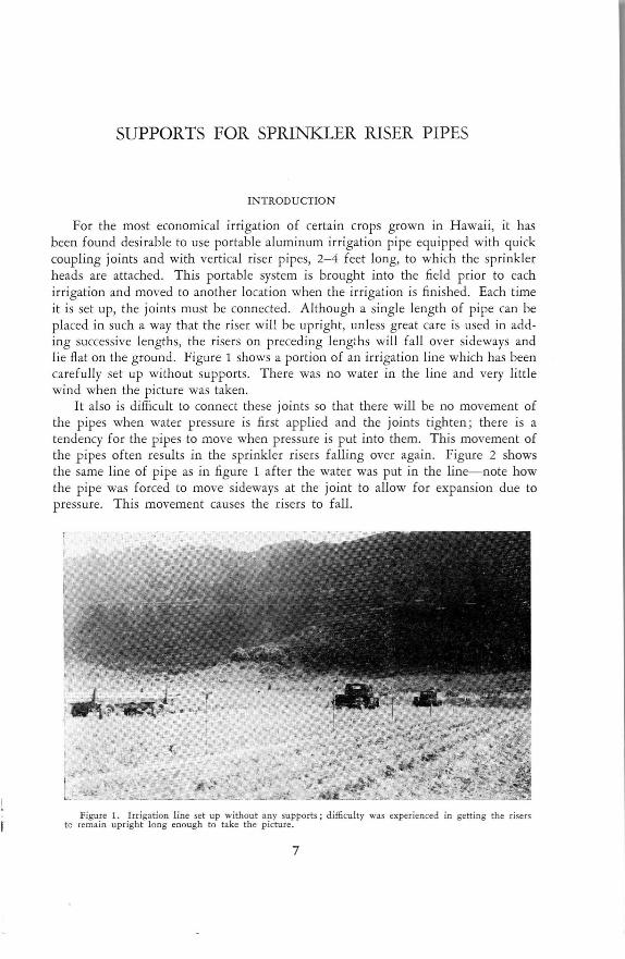
For the most economical irrigation of certain crops grown in H awaii, it has been found desirable to use portable aluminum irrigation pipe equipped with quick coupling joints and with vertical riser pipes, 2- 4 feet long, to which the sprinkler heads are attached. This portable system is brought into the field prior to each irrigation and moved to another location when the irrigation is finished. Each time it is set up, the joints must be connected. Although a single length of pipe can be placed in such a way that the riser will be upright, unless great care is used in adding successive lengths, the risers on preced ing lengths will fa ll over sideways and lie fl at on the ground. Figure 1 shows a portion of an irrigation line which has been carefully set up without supports. There was no water in the line and very little wind when the picture was taken.
It also is difficult to connect these joints so that there will be no movement of the pipes when water pressure is first applied and the joints tighten ; there is a tendency for the pipes to move when pressure is put into them. This movement of the pipes often results in the sprinkler risers falling over again. Figure 2 shows the same line of pipe as in figure 1 after the water was put in the line- note how the pipe was forced to move sideways at the joint to allow for expansion due to pressure. This movement causes the risers to fall.
Figure 1. Irrigation line set up without any supports ; d ifficulty was experienced in gett ing the risers tc remai n upright long enough to take the picture.
7

Figure 2 . Same l ine as in Figure 1 after water was turned into the line.
The trouble is more pronounced if there is a strong wind when the pipes are being joined or when pressure is being built up . Once the sprinkler risers have fallen over when there is pressure in the line, they are difficult to straighten up unless the water pressure is shut off, and this is a time-consuming operation. There are several commercial attachments which will keep short risers upright where there is no wind. None of these have proven satisfactory where a 3-foot riser is used and a brisk wind prevails.
RE Q UIREMENTS
A practical riser support must be economical, it must be designed for quick and easy installation, and it must be compact so as to require small storage space when not in use and be eas ily transported from one field to another.
DESIGN OF SU PPORTS
With these principles in mind, three riser supports were designed, and then tested at the W aimanalo Experimental Farm. They will be referred to as types A, B, and C.
T ype A is constructed entirely from 5/ 16-inch round steel. It is essentially an inverted 90° V with 6-inch legs perpendicular to, and extending into, the ground surface. An elliptical hook made of the same material, and cut open on one side, is attached to one side of the V as near to the apex as possible.
When the riser support is rotated 45 ° so that the hook is in a horizontal plane, the hook will slip on the riser pipe ( fig. 3). When the support is returned to its normal position, the hook is clamped on the riser pipe. Pushing the legs of the support into the ground completes the installation, as shown in figure 4. Six feet of steel rod are required for the support. Each of the supports weighs about 1 y2
8
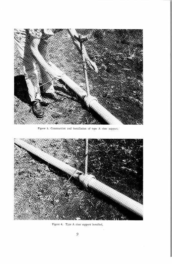
Figure 3. Construction and installation of type A riser support.
Figure 4. Type A riser support installed.
9

Figure 5. Condi tion of same line as in figures 1 and 2 after water pressure has built up when using riser supports.
pounds. Cost of material for the supports is about 22 cents each when purchased in Honolulu at the present time.
Type B (fig. 6) is made with the same kind of hook as type A. One half of the V is omitted, and the remaining leg is bent at 90° to the supporting rod so that the leg enters the ground at a 45° angle. This support will require about 3V2 feet of steel rod ; the cost of material for each support will be about 13 cents.
In making type C ( fig. 7), the inverted V with the short legs is made in the same manner as in type A. Instead of using the open, elliptical hook which was welded to one side of the V, a spring clip of the type used on tool boards was fastened to the apex of the V. To install this type, the legs are first pushed into the ground, and then the spring clip pushed onto the riser pipe. This results in somewhat faster installation. Type C requires 5 feet of 5/ 16-inch round steel rod. Cost of the steel rod and spring clip will be about 29 cents for each support.
TESTING
When these three types of supports were tested under field conditions at the Waimanalo Experimental Farm, type A held the riser pipes firmly in place while the line was being installed and the pressure was being built up, as well as preventing the wind from blowing the pipes over during operation. Type A also meets the original criteria for economy, ease of operation, and compactness. This support is recommended for all applications.
Type B satisfactorily prevented the wind from blowing the riser pipes over after pressure was in the lines, but did not hold the risers upright while the pressure was building up . This type could be used in semipermanent installations where irrigation pipes stay in one field for the duration of a crop.
Type C, like type B, was satisfactory for keeping the riser pipes upright after pressure was in the line, but the spring clips did not withstand the thrust caused by pressure building up in the pipes; the riser pipes kicked out of the clips. Since
10

this type is more expensive than type A, and does not function as well, it is not recommended.
Since type A design was found to be superior to the other two types in field tests, detailed instructions for its construction are given. Type B, being a modification, can easily be built using the same plans and figure 6.
CONSTRUCTION
For economy, all supports used in any installation shou ld be manufactured at one time. If this procedure is followed, a more or less mass production technique in manufacturing can be used.
The only material used in this support is hot rolled, mild steel, 5/ 16-inch in diameter. Allow about sy2 feet of stock for each support to be built.
In order to produce these supports economically, they should be built in a shop which has a reasonable amount of metal-working equipment. The minimum set of tools contains the following:
1. Welder's table ( a table with a steel frame and a flat steel top). The dimensions of the table top should be at least 3 X 4 feet, and the table should be anchored firmly to the floor.
2. Oxyacetylene heating and cutting torches. 3. Electric arc welding equipment. 4. Grinding wheel.
Figure 6. T ype B Support.
11

Figure 7. Type C Support.
5. Vise, anvil, and hacksaw. 6. Blacksmith hammer. 7. Steel tape . 8. Two or three C clamps. 9. Several small pieces of angle iron.
10. Piece of 7-inch pipe about 2 or 3 feet long.
The first step in construction is to cut 5 feet of rod for each support. Next, sharpen these rods on both ends. Sharpening is easier if done while the rods are still straight and easily rotated. The sharpening can be done on a coarse grinding wheel, or the ends of the rods can be heated and the points drawn out on an anvil wi th a hammer. If forging is used to sharpen the points, the rods can be cut a little shorter than 5 feet, since they will be lengthened by drawing them out to a point with a hammer.
Lay out a full-scale chalk drawing, showing the size and shape of the rod after it is bent, on the top of the welding table. At each of the three places where a bend occurs, a piece of angle iron should be tacked to the table on the inside of the curve. A fourth piece of angle iron should be tacked in place on the outside of one of the legs to act as a stop against which the leg will rest while it is being bent. To speed the location of the first bend, it may be desirable to place another stop 6 inches below the first bend . This should be as close to the edge of the table as possible so that a C clamp can be placed on the rod to hold it firmly in place. Once the rod is in place, it can be heated and bent at each corner in sequence.
After all the rods have been bent into shape, the hooks are formed by using another fixture made from two pieces of 1-inch pipe, each of which is from 1 to 1V2 feet long. Saw a piece longitudinally from the side of each of these
12

RISER Pl PE IIIWG. Ne, 2 l'IIOJECT ND 7 3 . 5- C DIH.IY RES DATE9-27-54 QtlCIID IY ,c,u,V2''= I"
Material: Mild Steel
1 11
Riser pipe
V
AGRICULTURAL ENGINEERING DEPT,
UNIVERSITY OF HAWAII
J?UPPORT FOR SPRINKLER
Fixture for
Forming Hooks
Figure 8. Construction drawing of support.
13

pieces of pipe so that the remainder has a depth of 1 inch. This is best done with a hacksaw, since the heat generated by a cutting torch will warp the pipe. These two pieces are then placed with the flat sides together, and a welding bead is run down each seam as shown in the upper left-hand corner of figure 8. This pattern, or fixture, is then secured in a vise. One end of the rod which is to be formed into hooks can now be tacked to one end of the pattern, or secured with it in the vise. The rod can then be heated with the oxyacetylene torch and bent around the pattern in a continuous spiral. If the rod is heated only on the curved portion of the oval, and is not pulled down too tightly, the entire spiral can be removed from the pattern by tapping with a hammer. One side of the lo/s-inch opening can now be located and marked, and the hooks cut apart on this line. After they have been flattened, the other side of the opening can be located and cut.
If the spiral is too tight to be removed intact, cut out a section about 1/z-inch wide through the middle of one side with the cutting torch. The individual hooks can then be removed from the pattern, flattened out, and cut to size. After the hooks are cut to size, they can be welded in place on the rods which were previously bent to shape.
This completes the riser supports; they are now ready for installation.
14

UNIVERSITY OF HAWAll COLLEGE OF AGRICULTURE
HAWAll AGRICULTURAL EXPERIMENT STATION HONOLULU, HAWAll
GREGG M. SINCLAIR
President of the University
H. A. WADSWORTH
Dean of the College and Director of the Experiment Station
Related Documents