The Study on Comprehensive Disaster Prevention around Mayon Volcano SUPPORTING REPORT (2) (Part II : Feasibility Study) XVI : Facility Design

Welcome message from author
This document is posted to help you gain knowledge. Please leave a comment to let me know what you think about it! Share it to your friends and learn new things together.
Transcript

The Study on Comprehensive Disaster Preventionaround Mayon Volcano
SUPPORTING REPORT (2)
(Part II : Feasibility Study)
XVI : Facility Design

i
SUPPORTING REPORT (2) - XVIFACILITY DESIGN
Table of Contents
Page
1. ADOPTION OF CSG METHOD TO SABO STRUCTURES ......................... XVI - 11.1 Description of CSG Method ....................................................................... XVI - 11.2 Construction Sequence of CSG Method ..................................................... XVI - 71.3 Discussion for Mixing Method and CSG Method ...................................... XVI - 91.4 Sampling Test for CSG Method................................................................ XVI - 121.5 Comparison between INSEM Method and CSG Method......................... XVI - 14
2. SAND POCKETING WORKS ....................................................................... XVI - 162.1 Construction of Structural Components.................................................... XVI - 162.2 Sabo Dam.................................................................................................. XVI - 172.3 Training Dike ............................................................................................ XVI - 242.4 Volume of Construction Works ................................................................. XVI - 26
3. CHANNELING WORKS ............................................................................... XVI - 263.1 Training Dikes........................................................................................... XVI - 26

ii
List of FiguresPage
Figure XVI 1 Facility Design of Pawa- Burabod River ......................................... XVI - 31Figure XVI 2 Facility Design of Anoling River ..................................................... XVI - 32Figure XVI 3 Facility Design of Budiao River....................................................... XVI - 33Figure XVI 4 Enlarged Front View of Sabo Dam .................................................. XVI - 34Figure XVI 5 Location Map of Dike Profile No.2 and No.2 in Figure XVI 7 ....... XVI - 35Figure XVI 6 Location Map of Dike Profile No.3 and No.4 in Figure XVI 7 ....... XVI - 36Figure XVI 7 Profiles of Dike ................................................................................ XVI - 37

XVI - 1
SUPPORTING REPORT (2) – XVIFACILITY DESIGN
1. ADOPTION OF CSG METHOD TO SABO STRUCTURES
1.1 Description of CSG Method
This report recommends a CSG method (the Cemented Sand and Gravel method)for Sabo structures on the Mayon Volcano. The reasons are as follows:
! Since the construction is on a large-scale with wide construction yard, CSG issuitable to the roller compact method.
! The construction site is abundant in good materials available there.! The strength of the soil used in the existing installations can be improved.
(1) Summary of CSG Method
The CSG method has been developed in order to construct fill dams moreeconomically and effectively by utilizing the materials in the sites or in thevicinity of the dam sites.
The CSG method can make fill dams stronger by improving materials. In order toimprove embankment materials such as sands and gravel in the riverbed, cementsare added and then both the cements and the materials are mixed together
After the cements and the fill dam materials are mixed at the construction site, themixtures will be transported by dump trucks or other vehicles. Then themixtures would be spread by bulldozers and rolled by vibrating rollers to improveembankments. There are other roller compacting methods as follows:.

XVI - 2
Description of Roller Compacting Methods
Soil Cement CSG INSEM RCC RCDGoals ofDevelopment
FoundationImprovement
Simplification ofFill Dam
Effective Utilizingof MaterialsAvailable atConstruction Site
Rationalizationof DamConstruction
Rationalizationof DamConstruction
Materialss/a <4.75mm
FlabbyFoundation,Clay
With no Grade ProcessingEliminate over 80"150mm
Material with Adjusted Grades/a20"60% s/a30"35%
Volume ofCement
60"160 70"160 120
Strength, Mpa 1.5"3 1.5"3 16 16
Notes: ! s/a: Fine aggregate ratio: a ratio of fine materials of 4.75mm in diameter and under to wholegrains.
Mpa=MN/m2
9.8MN/m2=100kg/cm2
! Soil cements are mainly utilized to improve the foundations.! Materials with even grade aggregates constructed by the RCC method or the RCD method can
expect to exert the same strength as a normal concrete.! Through the RCD method, construction joint, bonding, curing and et al. should be done
thoroughly under strict supervising and management.! The INSEM method is preferable for small-size structures in mountain streams.

XVI - 3
Construction Procedure for CSG Method
XVI - 4
(2) Characteristics of CSG Method
The characteristics of the CSG method are as follows:
! Effective utilization of the materials which can be obtained in constructionsites.
! Intensification of the materials by the CSG method stronger than those of filldams. It is possible to construct a structure with steep slope gradient.
! Construction of the CSG method is almost the same as that of fill dams.However, compared to soil core frame structures, this method can shorten thecompletion date, because materials made by the CSG method are water-resistant.
! More economical and effective constructions by utilizing characteristics of thetopography, geology and materials of the site.
! It is necessary to construct cutoff zones, because CSG does not set a cutoffcondition completely.
Therefore, the CSG method is effective for large-scale structures with conditionsthat there are plenty of materials in the construction site, that construction yardsare wide, and that the cutoff condition will not cause serious problems.
As for stability of structures while designing, we will examine both the concretegravity dam and the fill dam.
(3) Actual Achievements for CSG Method
The CSG method is already adopted as below : In the temporary cofferdam ofupstream fill dam, and in the wing of sabo dam in the Unzen-Mizunashi River.Also, in the consolidation work in the Sacobia River at the Pinatubo Volcano inthe Republic of the Philippines, the CLG method, the Cemented Lahar Gravelmethod, is adopted.
Compared to the CLG method, work volume of this Study which is 450,000-500,000m3 is larger than that of the CLG method.

XVI - 5
Typical Constructions for CSG Method
HightName Location Year Overflow
(m)non-over
(m)
Length
(m)
CrownWidth
(m) Slope
Volume
(m3)Nagashima Cofferdam Japan Shizuoka 1992 14.9 86.5 5.0 0.8 30,000Chubetsu Cofferdam Japan Hokkaido 1994 4.0 60(281) 5.0 1.2 2,500Kubusu Cofferdam Japan Toyama 1994 9.0 12.0 87.5 4.0 1.2 13,650Surikami Retaing wall Japan Fukushima 1996 (21.0) 23.5 120.0 5.0 1.0 14,500
Mizunashi 1 Sabo dam wing R Japan Nagasaki 1995 (14.9) 10-20 270.0 5.0 1.2 40,000Sabo dam wing L Nagasaki -1996 (14.9) 10-20 280.0 5.0 1.2 110,000
Mizunashi 2 Sabo dam wing R Japan 1997 (14.5) 5-12 230.0 5.0 1.2 25,000
Maskup Consolidation dam Philippine Panpanga 1997? 6.5 8.2 494.0 5.0 2.0CLG: Cemented Lahar Gravel
(4) Characteristics of Materials for CSG Method
The material used in the CSG method vary greatly as the following table indicates.The riverbed materials in the Mayon Volcano and the characteristics of Lahardeposits are effective as the materials of CSG. Also, these materials have goodfeatures for CSG as below :
! The specific gravity of Lahar deposits is as large as around 2.65.! The grade distribution of Lahar deposits is that there are little clay under
0.075mm in diameter, and the fine aggregate ratio (s/a) is from 30 to 45.Therefore, the Lahar deposits show the grade distribution which is near thestandard aggregate of the RCD method. In this case, zero slump concrete isused.
Characteristics of Materials for CSG Method
Nagashima Chubetsu Kubusu Surikami Mizunashi MaskupRiver bed material Volcanic material
<4.75mm s/a (%) 20-40 30 14-38 40-50 60 95-99<0.075mm 0 0 0 5-8 5-10 3-17
Uniformity coefficient Uc 12-19 78 17-37Specific gravity 2.6 2.6 2.60-2.66 2.3-2.4 2.3-2.4 1.96-2.41Absorption (%) 1 1 0.9-2.1 11 4-10 5-13Moisture ratio (%) 5-7 5-8 4-7 15-18 5-12Cohesion c 0.33 0.71 1.4 1.3 0.35-0.75Internal friction angle # 42 45 42 43.5 41-44

XVI - 6
Characteristics of Materials for CSG Method in Mayon Volcano
Sieve Analysis Specific Density s/a (%)<80mmBasin d50
(mm)d90
(mm)Gravity Test
(g/cc)Type A
(%)Type B
(%)Yawa 96.75 170.25 33 - 38
Pawa Burabod 344.00 486.00 2.658 2.364 27 - 49 93Budiao 73.60 276.40 18 - 42 61Anoling 189.20 266.00 2.712 2.384 34 - 51
Average 175.89 299.66 2.685 2.374 28 - 45 77Lahar 50 - 65 80 - 90
(5) Construction Procedures for CSG Method
The construction procedure of CSG method consists of extracting materials,mixing, transporting, placing, and compaction. The only difference in adopting theCSG method this time from the previous constructions is that in mixing we useeither backhoe or plant as indicated in following table. In a large amount ofconstruction, a plant is generally preferred. Also, as the table shows, by usingplant, we can increase the amount of construction per day.
Description of Construction by CSG Method
Nagashima Chubetsu Kubusu Surikami Mizunashi MaskupCement Portland blast
fumace cementType B
Portlandcement
Portland blastfumace cement
Type B
Portlandcement
Portland blastfumace cement
Type B
Portlandcement
80 140?Cement content 80 60 60 60 80
4.7% 8%Water content 5-8 4-7 16-20 8-12Mixing Backhoe 0.6m3 Backhoe Belt conveyor Backhoe Bucher x 2Transporting 11t Dump truck Dump truck Dump truck 11t Dump truck 8t Drump truckPlacing 21t Bulldozer
17cm x 310t Bulldozer
25cm x 216-21t Bulldozer
25cm x 210t Bulldozer
25cm x 216t Bulldozer
25cm x 2Compaction 8t Vibrating
Roller10t Vibrating
Roller8t Vibrating
Roller10t Vibrating
Roller7-10t Vibrating
Rollertime 6 6 6 8 6
Compressive Strength 2.0-3.0 2.0-3.0 2.0-4.5 1.5-3.0 3.0-1.7 2.7-3.1 6.8-8.4average 2.2 3.3 6.0 2.94 7.63
Volume m3/day 400-600 500 500 400-500 1500-2000
Unit of compressive strength: Mpa 106N/m2 = N/mm2

XVI - 7
(6) The Reasons for Adopting CSG Method to Yawa River Project
We have decided to adopt the CSG method to the Yawa River project for thefollowing reasons:
! The construction scale is big (450,000-500,000m3 in CSG amount) and issuitable for the construction using large construction machines and vehicles.
! There are a large amount of materials which can be obtained in theconstruction sites.
! The wide construction yard is suitable for the roller compact method.! The characteristics of the materials will assure desirable structural strength.! Existing Sabo dam facility which is made by concrete tends to be destroyed
because of scouring or piping. But, if the width of dam body is enough, thestructures built by the CSG method are less prone to be destroyed than thoseconcrete structures.
! Also, in the case of insufficient width and with little maintenance andoperation, the conventional training dike, whose soil is packed materials andwhich has 1.0m depth of embankment, was destroyed due to gravel bump andrunoff of packed soil by scouring. In such a case, if CSG is adapted to thepacked materials, it is possible to reduce maintenance and operation becausethe strength of the materials increases.
1.2 Construction Sequence of CSG Method
(1) Description of Cement and Composition of CSG Method
In Japan, Portland blast furnace slag cement type - B is used due to the marketsituation. This type of cement is low in exothermic amount, and has no problem inresistance to chemical reaction and in controlling alkaline aggregates reaction.
From previous cases, the amount of the cement needed is estimated to be around80kg/m3 , and the moisture ratio to be around 10%. But composition variesaccording to materials, so confirmation by experiment is necessary.
The composition of CLG (Cemented Lahar and Gravel) used in Pinatubo Volcanois as follows:

XVI - 8
Composition and Strength of CLG
Minimum CementContent per m3
kg(bag*)
MaximumWater/Cement Ratio
kg/kg
Designated Size ofCoarse Aggregate
Square Opening Std.mm
Minimum CompressiveStrength of 150 x 300mm
concrete cylinderspecimen at 28 days,
MN/m2(psi)Cemented Lahar andGravel (CLG)
80(2 bags) 2.43 Maximum
150mm3.5
(508)* Based on 40 kg/bag
Water content after mixing shall be between 8% and 12%, and minimum dry density shall be 1.85 tf/m3.
(2) Mixing by Batcher Plant of Cemented Sand and Gravel
Two types of mixing are feasible : backhoe mixing and batcher plant mixing.
In a large scale construction, plant mixing has more advantages than backhoemixing, because plant mixing has good construction strength, and thereby is moreeconomical.
Backhoe mixing is inferior to plant mixing in that it is weak in quality control andhas less strength.
However, in case of doing mixing in the smaller yard, those problems of backhoemixing can be solved and backhoe mixing is more economical.
(3) Transportation of Cemented Sand and Gravel
CSG should be transported quickly by dump trucks to the site to preventsegregation. If the construction site is far from the mixing yard, the water inCSG would evaporate. In CSG method, management of water content in percentof total weight is most important. So, in transporting, it is necessary to be carefulof water evaporation.
(4) Placing Concrete by Dump Truck and Bulldozer for Cemented Sand andGravel
The placing of CSG transported by the dump truck is done by bulldozers.
Previous cases indicate that 50cm- compaction with two 25cm-thick layers isdesirable.
(5) Compaction of Cemented Sand and Gravel
Self-propelled vibrating roller for soil materials is used for CSG compaction.
The compaction mechanism by vibrating roller is considered as the compaction ofrolling from the empty weight of the vibrating roller and the fluidity of mortarfrom abrasion loss among aggregate by the vibration of vibrating roller.

XVI - 9
The roll frequency of vibrating roller is estimated by observing the nearly nosubsidence of roller and the emergent of cement paste on CSG surface.
Since the result of compaction will vary greatly according to thesoil,composition,compaction machine, and construction method, in the actualconstruction, a test construction is necessary before the work in order to determinethe depth of compaction and the most appropriate rolling frequency, etc. based onthe construction machine.
(6) Edge Treatment
Land grading is implemented after passing the CSG on 3 or 4 times with bucket ofthe backhoe. As for the construction method, two-layer land grading with goodroll is desirable from the experience of sabo dam construction in the MizunashiRiver.
(7) Treatment of construction joint, expansion joint and curing
In case of resuming placing or pouring after a long interruption, it is necessary toclear the placing or pouring surface to remove waste or stagnant water and keepthe wetness.
After depositing CSG, appropriate curing is necessary. Especially wheninsulation is so strong that CSG might dry up, just after compaction curing such ascovering the CSG surface with seats is necessary.
(8) Manegement in case of Constructions
The management of CSG is implemented by observing the moisture ratio,unconfined compression strength, and dry density of the concrete cylinder.
1.3 Discussion for Mixing Method and CSG Method
The mixing methods for improving foundation by using cement and the materialswhich can be obtained at the construction sites are divided into two types as below.Taking economical and construction efficiency into consideration, in the CSGmixing at the Mayon Volcano, plant mixing method or backhoe mixing methodwould be suitable.

XVI - 10
Mixing Method
Plant Mixing Method
Mixing Method on the Site
Existing Plant Mixing Method
New Plant Mixing Method
Ordinary Plant Mixing Method
Mixing Method in Fixed Location
Yard Mixing Method
Mixing Method on the Original Ground
Mixing Method on the Road (t<1m)
Mixing Method in Shallow Layer (t=1-3m)
Classification of Mixing Method
The characteristics of each mixing method are as below :
(1) Plant Mixing Method
In plant mixing method, cement, the materials which can be obtained inconstruction sites, water, and so on are mixed in the placed plant according to thedesignated composition ratio. This method is suitable for a large scale structuresand the quality after mixing is high in reliability. The accuracy of plant mixingmethod is high in general, but when the materials which can be obtained inconstruction sites contain much silt and clay, mortar sometimes sticks to the drumand the fan in the mixer, or big coarse aggregate might be discrete. Also, plantmixing method is suitable for large scale construction regarding its economicalefficiency, so at present it is difficult to apply this method to middle-scale saboworks.
Taking into consideration that, as real economical efficiency for the new plant, theamount of placing or pouring is more than 30,000-50,000m3 , the adoption of anew plant is limited to the case such as setting a large scale installation or morethan one sabo installations. Therefore, in this plan which needs about 50,000m3
CSG just for the Yawa River, there exists a good reason for adopting a new plant.
(2) Mixed Methods of Backhoe
Backhoe mixing method is meant by two methods.
① one in which materials are directly mixed at the construction yard.② one in which materials are mixed at the mixing yard apart from the
construction site and then transported to the construction site.
The method ① is more often adopted due to its convenience. However, since thismethod has several problems as follows, we recommend the method ②.

XVI - 11
! In mixing at the construction yard, it is difficult to measure the materials andthe dispersion of the amount of cement mixed is large.
! In mixing at the construction yard, there exists a risk to do damage to theembankment surface of existing facilities and thereby the embankment isprone to have weak structure.
! Since almost all the work is done intensively at the construction site, not onlyis quick construction difficult but it is also necessary to dispose many workersand a lot of machines and vehicles at the relatively narrow construction yard.In our field investigation we adopted backhoe mixing (mixing yard method),for the CSG mixing method and the result of mixing was generally good. It isrecorded that the work-hour of mixing with this method was around oneminute per 1m3 .
(3) Comparison of Mixed Methods of Backhoe and others
The comparison of each mixing method is as follows, and as for the constructionin the Yawa River we consider mixing by mixer as more economical.
Finally, since homogeneous quality of CSG is expected, we recommend the mixermixing as the mixing method for the construction in the Yawa River.
Comparison of Mixing Methods of Backhoe and Others
Cement Mixing Methods Backhoe Mixing Mixer Mixing
Construction Volume (m3) 500000Construction Condition
Construction Volume per day (m3) 2000Standard (m3) 0.6 1.2 3.0
Construction Ability (m3/hr!Vehicle) 60 120 162
(m3/day!Vehicle) 420 840 1134
Required Number (Vehicle!Machine) 5 3 2Mixing
(420$5=2100) (840$3=2520) (1134$2=2268)
Construction Ability (m3/hr!Vehicle) 35 70
(m3/day!Vehicle) 245 490
Number of Required Vehicles(Vehicle!Machine) 9 5
Ability ofConstructionMachine andRequired Number
Loading
(245$9=2205) (490$5=2450)
Summation (Vehicle!Machine) 14 8 2
Number of Men Required (Men/day) 42 24 18Running Cost (Yen/m3) 5400 5400 4800
(Yen/Vehicle) 100000 100000 10000000
(Vehicle) 14 8 2(Yen) 1400000 800000 20000000
Cost ofAssemblingScrapping andTransporting
(Yen/m3) 2.8 1.6 40.0
ConstructionCost
Direct Construction Cost (Yen) 5403 5402 4840

XVI - 12
1.4 Sampling Test for CSG Method
(1) Laboratory Investigation
The CSG method uses the materials which can be obtained in construction sites.In the first place, laboratory investigation is to be done as is indicated in the chartbelow.
Sampling ofMaterials
Soil Density TestSpecific Grarity Test andAbsorption TestMoisture Ratio TestGraiding TestCompaction TestTriaxal Compression Test
Determination ofCSG Materials
Mixed Proportion of Cement:80kg/m3
Moisture Ratio 4 cases,Material 7 cases, 28 DaysUniaxial Compression Test
Determination of the mostsuitable Unit Water Volume
Uniaxal Compression TestMixed Proposition: 80kg/m3 and twocases, Material 7 cases, 28 Days
Endurance TestMixed Proportion 80kg/m3 andtwo other cases
Assessment
Proposal of Mixed proportionMixed Proposition of Cement ConstructionMoisture Ration, Soil Density and others
Flow Diagram of Laboratory Test for CSG Composition

XVI - 13
The items and contents of laboratory investigation are indicated in the figurebelow.
Content of Laboratory Investigation
Item ContentTest of Materials Identify the quality of the materials obtained upstream of Sabo dam and
aggregate bought, by physical and dynamics tests.
DeterminingCSG Materials
Determine whether the materials are good for CSG. Firstly, add cementto the materials, which can be obtained in construction sites, and mix.Then, conduct physical and dynamics tests.
Test of the CSGQuality
By quality tests for Strength、Percolation、Endurance, determine the CSGcomposition ratio indoors and examine the relation to moisture ration,then suggest the standard values for management.
(2) Field Investigation (Experimental Construction)
After identifying the quality of the materials by laboratory investigation andsetting the moisture ratio and the amount of cement, field investigation (testconstruction) is needed. The purposes of this investigation are as follows :
! Confirmation or correction of the basic composition determined by laboratoryinvestigation,
! Command the property of CSG during mixing and after solidification,! Determination of the construction method, and! Proposal of the standards and the method of management.

XVI - 14
The procedure of the field investigation (test construction) is as follows:
Collecting Materials & Sorting
Transport & Temporally Placing
Material Test
Mixing
Preparation of Samples
Placing
Measurement of Transporting Time
Compaction
Measurement of Transporting Time and Placing Speed
Curing
Measurement of Rolling Time, R1 Density Experiment
Field Density Experiment, Compressive Strength Test and et al.
CSG Transport & Unloading
Construction Procedure of Field Investigation
1.5 Comparison between INSEM Method and CSG Method
The INSEM method is suitable for the construction in the mountain stream wherethe construction yard is small and the processing of the materials which can beobtained in construction sites is difficult. With this method, wastes can beprocessed within the construction yard. This method is basically the same as theCGS method, but construction scale can be small.
The INSEM method tries to make a series of construction process, from addingcement to soil, to compaction in the thin layer, and to anchorage simply andeconomically by using just earthmoving machines. Therefore, the idea of theINSEM method differs from the ideas of this plan in that this plan is a big scaleworks with a large construction yard and plans to exploit the materials and wastesother than soil produced by the work.

XVI - 15
Comparison between INSEM Method and CSG Method
CSG INSEM RCD Concrete
Basic Concept
Originally developed forTemporary Coffer Dam : inorder to reduce the crosssection of fill dam, by mixingcement and the materials whichcan be obtained at theconstruction site, C and Φ areimproved. Through theconstructions such as Unzensabo dam, Fujigawa sabo dam,the focus has been on the use oflow quality concrete.
Developed in order to exploitall the sediment yield at theconstruction site and thereby toeliminate transportingsediment. Discussed byRokko Kouji Jimusho.
Placing and rolling ultra self-consistency concrete tostreamline dam constructionmethod. Originally developedin Japan in order to make RCCconcrete as strong as ordinaryconcrete.
Idea of Strength
1) The conception of the filldam : Temporary coffer damfocusing on improving C andΦ,
2) The conception of theconcrete dam : Mainlyfocusing on the compressionstrength ( e.g., constructionsat Unzen and Fujigawa sites)
The conception of the concretedam: The compressionstrength of the dam body isgreat. The compressionstrength of the apronfoundation and leave buffer isimproved. During theconstruction, the compressionstrength is at the middle level.
The conception of the concretedam: Mainly focusing on thecompression strength
UnconfinedCompressionStrength Goal CN/mm2
Unzen : 3.0
Fujigawa : 6.0
About 1.5-4.0 18
Grain Size No Grain Disposal Cut OFF:150mm
No Grain Disposal Cut OFF:80mm
Grain Adjustment
From our experiences, FineAggregate Ratio (s/a) of 30 to40% is desirable
Gravel and/or disintegratedgranite from weathered granitein Mt. Rokko. Fine AggregateRatio (s/a) is around 50%.
ConstructionMethod
The construction methods of CSG and INSEM are basically thesame: Placing and rolling self-consistency concrete.Processing the construction joints, joint cutting and curing are notdone basically.
Construction Joint, JointCutting, Curing
Volume ofCement (kg/m3)
Temporary Coffer Dam: 60-80
Mizunashigawa Sabo Dam: 80
Fujigawa: 100-160
Stepped Apron Foundation:70-100
Leeve Filling: 100-130
INSEM Dam: 130-160
EarthmovingMachine
Large earthmoving machinesfor streamlined construction
Small earthmoving machinesfor sabo construction site
Large earthmoving machinesfor streamlined construction
Mixing Mixer, Badkhoe Badkhoe Plant
Transporting Dump Truck Dump Truck Dump Truck
Placing Bulldozer Bulldozer, Badkhoe
Compaction Vibrating Roller Vibrating Roller Vibrating Roller

XVI - 16
2. SAND POCKETING WORKS
2.1 Construction of Structural Components
Sand pocketing consists of the sabo dam which traps and accumulates the debrisflow and the training dike which lead the debris flow to the sabo dam.
Sketch of Sand Pocket Facility Component
XVI - 17
2.2 Sabo Dam
(1) Types of Sabo Dam
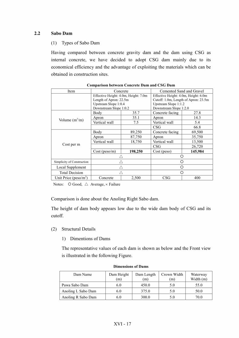
Having compared between concrete gravity dam and the dam using CSG asinternal concrete, we have decided to adopt CSG dam mainly due to itseconomical efficiency and the advantage of exploiting the materials which can beobtained in construction sites.
Comparison between Concrete Dam and CSG DamItem Concrete Cemented Sand and Gravel
Effective Height: 4.0m, Height: 7.0mLength of Apron: 22.5mUpstream Slope 1:0.4Downstream Slope 1:0.2
Effective Height: 4.0m, Height: 6.0mCutoff: 1.0m, Length of Apron: 23.5mUpstream Slope 1:1.2Downstream Slope 1:2.0
Body 35.7 Concrete facing 27.8Apron 35.1 Apron 14.3Vertical wall 7.5 Vertical wall 5.4Volume (m3/m)
CSG 66.8Body 89,250 Concrete facing 69,500Apron 87,750 Apron 35,750Vertical wall 18,750 Vertical wall 13,500
CSG 26,720Cost (peso/m) 198,250 Cost (peso) 145,984
Cost per m
△ "Simplicity of Construction △ "
Local Supplement △ "Total Decision △ "
Unit Price (peso/m3) Concrete 2,500 CSG 400Notes: " Good, △ Average, $ Failure
Comparison is done about the Anoling Right Sabo dam.
The height of dam body appears low due to the wide dam body of CSG and itscutoff.
(2) Structural Details
1) Dimentions of Dams
The representative values of each dam is shown as below and the Front viewis illustrated in the following Figure.
Dimensions of Dams
Dam Name Dam Height(m)
Dam Length(m)
Crown Width(m)
WaterwayWidth (m)
Pawa Sabo Dam 6.0 450.0 5.0 55.0Anoling L Sabo Dam 6.0 375.0 5.0 50.0Anoling R Sabo Dam 6.0 300.0 5.0 70.0

XVI - 18
2) Design Discharge
The design discharge of each installations is as below :
Representative Values of Design Discharges
A
(km2)
R-day
(mm)
f re
(mm/hr)
Q1/3.6*re*A
(m3/s)
QpsC*/(C*-Cd)*Q
(m3/s)
a Qpa*Q
(m3/s)Pawa-burabod Sabo Dam 7.5 463 0.7 102.7 214 428 0.5 321
Training Dike 7.6 463 0.7 102.5 216 0.1 238
Anolong L Sabo Dam 6.6 458 0.7 103.1 189 378 0.5 284Training Dike 7.4 458 0.7 101.5 209 0.1 230
Anoling R Sabo Dam 8.7 458 0.7 99.4 240 480 0.5 360Training Dike 9.3 458 0.7 98.5 254 0.1 279
Anoling D Training Dike 16.9 458 0.7 91.0 427 0.1 470
Rainfall intensity
Rainfall intensity is calculated according to the method for rainfall intensityin the Technical Instruction (draft) for the measure of debris flow.
re =r2424
1.21
#24f2
C/60 # A0.22
0.606
Where r24 : Daily Rainfall (A twenty year return period)f : Coefficient of Runoff f=0.7C : Coefficient C=80, which coincides with discharge
in downstreamNormal Value: 60~180
A : Catchment Area
Pure Water Discharge
Qp = 1
3.6 # re #A(m3/s)
Flood Discharge
According to the Technical Instruction (draft) for the measure of debris flow,flood discharge is to be 1.5 times as big as pure water discharge, taking soilcontent into consideration.
Qp’ = 1.5 $ Qp

XVI - 19
Peak Discharge of Debris Flow
Qsp = C*
C* - Cd
Where C* : Bulk Deposition Concentration of Silted DepositionC*
=0.6Cd : Bulk Deposition Concentration of Debris Flow during
Moving: Cd≧0.3
Cd =% # tan &
(' - %) (tan ' - tan &) = 1.2 # tan 6.84(
(2.60 - 1.20) (tan 30( - tan 6.84()
' : Density of Gravel ' = 2.60t/m3
% : Density of Water %= 1.20t/m3
# : Internal Friction Angle of Silted Deposition # = 30゜& : Gradient of Bed Slope
3) Watereway
The waterway dimensions of each installation are as follows:
Waterway Dimensions of Installations
Discharge Width ofwaterway
Slope ofwaterway
Overflowdepth
Allowableheight
Height ofwaterway
Pawa-burabod Sabo Dam 321 55.0 1.2 2.19 0.80 3.00Anoling L Sabo Dam 284 50.0 1.2 2.15 0.80 3.00Anoling R Sabo Dam 360 70.0 1.2 2.02 0.90 3.00Allowable height is to be 0.8m.
The overflow depth is calculated with Seki's Formula in case of flood.
Q = 215 # C(2 # g)1/2(3 # B1 + 2 # B2)h3
3/2
Where Q : Flood Discharge Qp’ = 1.5 $ QpC : Coefficient of Discharge C = 0.6g : Acceleration of Gravity g = 9.8m/s2
B1 : Waterway Depth B1Waterway Depth is set as wide as possible taking Flow depth ofDebris flow into consideration.
B2 : Overflow Width (m)h3 : Overflow Depth (m)

XVI - 20
B1
B 2
H
△h
h3
Waterway Form
NB : Waterway Height>Debris Flow Depth.
4) Slit
In order to prevent lowering of the downstream riverbed by flood, andoverflowing of debris flow by trench fluctuation, a slit is to be adopted. In asmall flood, a slit can lead debris flow to the sabo dam by preventingdownstream riverbed from lowering, and by fixing trench. Also with afflux,the flowing soil from bed-load transport and traction can be controlled.
The configuration of the slit is given in the chart below. We propose theseslit configuration in order to secure enough scale to let the discharge of thetwo-year return period flow, and to let afflux exert adjustment effects.Reexamination of the details is necessary at the stage of detailed design.
Dam name Slit Height (m) Slit Width (m) Number Total WidthPawa Sabo dam 4.0 5.0 x 2 10.0mAnoling L Sabo dam 4.0 4.0 x 2 8.0mAnoling R Sabo dam 4.0 4.0 x 3 12.0m
(3) Dam Body, Cut off and Downstream Apron
1) Main Body Section
Main body section is designed as follows, so that CSG may be constructedwith non-formwork.
! Crown Depth: 5.0m (due to the width of Construction Machine)! Slope Gradient: 1:1.2 (due to the slope grading and construction feature
of compaction) Downstream slope gradient is generally 1:0.2, a steepgradient, but in this plan erosion protection using boulders at gentlegradient is necessary due to the non-framework construction method.Also, the downstream slope gradient is to be 1:2.0 from the experiences

XVI - 21
of consolidation work in downstream regarding gentle gradientinstallations.
The results of stability analysis are as follows:
As the stability analysis indicates, by securing enough width of the dambody, subgrade reaction of foundation in downstream can be reduced, whichis an advantage for the loose foundation of sand and gravel with smallbearing capacity.
Results of Stability Analysis
Pawa Sabo Dam Anoling L Sabo Dam Anoling R Sabo DamItem Safe
factor Calculation Decision Calculation Decision Calculation DecisionFlood Case
Sliding Fs 1,200 3,278 OK 3,278 OK 3,318 OKEcentric distance e 3,233 1,048 OK 1,048 OK 1,041 OK
down 'D 30,000 13,960 OK 13,960 OK 13,837 OKupper 'U 30,000 7,126 OK 7,126 OK 7,097 OK
OK OK OKDebris flow case
Sliding Fs 1,200 4,012 OK 3,746 OK 3,762 OKEcentric distance e 3,233 1,295 OK 1,287 OK 1,295 OK
down 'D 30,000 13,445 OK 13,524 OK 13,559 OKupper 'U 30,000 5,755 OK 5,823 OK 5,804 OK
OK OK OK
The conditions of stability analysis are as below:
Load Condition
List of Design Loads
OrdinaryTimes Debris Flow Flood
Dam Height isless than 15m
Hydrostatic Pressure,Pressure of SedimentationPressure of Debris flow
Hydrostatic Pressure
Stability Condition
1. The acting line regarding resultant force of empty weight and externalforce is to be within the one-third area of the center of the dam bottomso that the tensile stress at the upstream end of the dam may not occur.
2. No sliding between the dam bed and the foundation bed.3. The maximum stress in the dam structure must not exceed the
allowable stress of the materials of the dam. The maximum pressureagainst the dam foundation must be within the bearing capacity of thefoundation.

XVI - 22
In Case of Flood
In Case of Debris Flow
Sketch of Design Load

XVI - 23
2) Cutoff
Cutoff is set in order for the apron to be horizontal and for vertical walls toattach to the riverbed.
Judging from each riverbed slope, the length of the cutoff in the Pawa Riveris 0.5m, and 1.0m in the Anoling River.
3) Protection Works of Front Yard
The length of the protective works in the front yard was discussed andexamined with empirical formula and Bligh's Formula. Thus the safetyside values have been adopted.
Dimensions of Protection Works of Front Yards
Bligh formula Empirical Formulaq
m3/s/mD
(m)W
(m)L
(m)H
(m)h3
(m)h
(m)t
(m)l
(m)
Length offrontapron
Pawa-burabod 5.84 5.0 8.0 21.7 6.5 2.20 5.0 1.5 21.60 22.0Anoling L 5.68 5.5 8.4 22.5 7.0 2.20 5.5 1.5 23.10 23.5Anoling R 5.51 5.5 8.4 22.1 7.0 2.10 5.5 1.5 22.80 23.5
Form of Protection Works of Front Yards
Bligh's Formula
L = 0.67 Co Hb#q

XVI - 24
Coefficients of Infiltration (C0 )
Classification C0
Fine Sand or Silt 18 Fine Sand 15 Coarse Sand 12 Mixing of Sand and Gravel 9 Coarse Sand with Cobble 4"6
L : Length of Apron+ length of protection works for riverbed inDownstream (m)
C0 : Coefficient of Seepage Line (From among the level-4 to 6 coarsesand with cobble in the chart above, the maximum value 6 isadopted.)
D : The height between the height of crown of apron and the top of themain.
Hb : Generally, by measuring the height between the apron crown andthe top of the main body,Hb=D
q : Discharge in Unit Width (m3/s)
Empirical Formula
L = (1.5 ~ 2.0) (H1 + h3)L : Dimension between Main Dam and Counter DamH1 : Height of Main Dam measured from Apron Crown (m)h3 : Overflow Depth of Main Dam (m)
2.3 Training Dike
(1) Type of Training Dikes
We propose the three types, A, B, and C for the types of Training dike. Thesetypes are adopted respectively according to the flowing form of gradient and soilor the variation of the riverbed with the impact pressure and erosion. Thecharacteristics of the three types are as follows :
! CSG type is basically adopted in the section where gradient of the mountainstream is steeper than 1/30 and thereby debris flow is expected. This CSG typeis divided into the two types below.
! We recommend the type A, which use CSG entirely, in the sections ofupstream sand pocketing and along the trench which have the possibility ofoverflowing the crown.
! We recommend the type B, which use CSG only for the riverside, in thesections which have little possibility of overflowing the crown.

XVI - 25
! We recommend the type C, which protects the riverside of embankment withthe riprap, in the sections for bed-load transport or traction, whose bed slopeof the riverbed is gentle (less than 1/30).
Reference Book: Debris Flow Survey Points in Hazardous Mountain Streamsand Hazard Area (Draft), December, 1998 (Japanese Edition): Japanese OriginalTitle/DosekI-Ryu ni Kansuru Kiken Keiryu oyobi Kiken Kuiki no Chosa Yoryo(An)
In volcanic mountainous slope area which can be considered as a hazard area ofdebris flow, if the area has experienced debris flow, the actual steepness of theslope is referred to, otherwise the bed slope is to be set up to 2゜(around 1/30).
Past inundation experiences indicate that debris flows came to stop at the point ofaround 2゜bed slope.
(2) Structural Details
The crown width should be 4.0m or above taking into consideration theconstructional feature of the roll and the fact that the crown is used as a road.Especially, the embankment must be 6.0m with 1.0m allowable width on eachedge.
The basic effective height of dike is to be 5.0m, according to the fact that previousfluctuations of the riverbed were from 1.0m to 2.0m, and to the calculation basedon the formula: deposit depth 2.0m + water depth 2.2m+allowable height 0.8m.
! Embedment DepthDue to the 1.0-2.0m riverbed fluctuation, the depth of embedment of theexisting installations are short of 1.0m, thus the depth of embedment of thisplan is to be 2.0m.
! Slope GradientCSG is adopted to the case in which the slope gradient is 1:1.2 and theconstruction with non-framework is possible. The maximum standard slopegradient value 1:2.0 is adopted for embankment.
! Slope Protection against ErosionAt the riverside, riprap is done with Boulder Facing, and at inland vegetationthe mat is built as embankment in order to prevent erosion.

XVI - 26
(3) Foot Protection against Erosion
Gabbion is set up in order to prevent the foot part of the structures from erosion.In the upstream area where debris flow would collide, it is necessary to set upboulders all over the training dike at the time of channel grading.
References
The width of Gabbion must be at least 3.0m, judging from the formuli below.
B = Zs / sin & = 0.8*2.2 / sin35゜≒ 3.0Zs : Maximum Scouring Depth = 0.8 $ Design Flood Depth& : Angle of Repose & = 35゜
2.4 Volume of Construction Works
Volume of Installations
Concrete
DamBody
Concretefacing
Apron Verticalwall
Total Boulderfacing
CSG Excava-tion
Enbank-ment
Gabbion
Coco fibererosion
control netwith seed
Cost
(m3) (m3) (m3) (m3) (m3) (m3) (m3) (m3) (m3) (m3) (m2) (peso/m)
2,500 2,000 400 120 200 1,500 40
Sabo dam Overflow portionPawa-Burabod Rv Sabo dam 26.72 13.50 5.40 45.6 64.4 87.3 150,200
Anoling Sabo dam 27.84 14.25 5.40 47.5 66.8 90.6 156,300Sabo dam Non-overflow portion
Pawa-Burabod Rv Sabo dam 24.92 24.9 117.3 57.1 116,000
Anoling Sabo dam 24.92 24.9 117.3 71.0 117,700
Training Dike Type A 6.59 6.6 5.5 65.0 34.3 3.0 62,100
Training Dike Type B 1.26 1.3 5.1 35.3 22.7 40.0 3.0 15.3 43,400
Training dike Type C 6.5 7.8 67.8 3.0 18.3 32,700
3. CHANNELING WORKS
3.1 Training Dikes
(1) Type of Training Dikes
Different types of training dikes are adopted according to the soil flowing formand the topography of the construction site.
! CSG type area is found where riverbed slope is more than 1/30, trench is notformed, and inundation is expected due to the accumulation of soil.
CSG type area :
! Bank protection type area is found where riverbed slope is less than 1/30, bed-load transport or traction occurs, and trench is likely to be formed.

XVI - 27
Bank protection type area: the downstream area from the crossing point of rightand left sides of the Pawa-burabod River and the Anolimg River.
(2) Detailed Structures
CSG Type
! Crown WidthSince the design discharge is less than 500m3/s, the crown width in this plan isto be 3.0m, in relation to the crown width of embankment.
! Dike HeightThe effective height is set by the formula (water depth+allowable height), towhich the 2.0m depth of embedment is added to set the dike height.
! Slope GradientThe slope gradient is to be 1:1.2 so that non-framework construction may bepossible.
Itemized Statement of Calculated Bank Protection Height
Discharge (m3/s)River Name Year Pure
WaterDebrisWater
RiverWidth
(m)
BedSlope1/n
SidewallSlope1:m
Rough-ness
n
WaterDepthh1(m)
SectionalAreaA(m2)
WettedPerimeterP(m)
HydraulicRadiusR(m)
Velocity
V1(m/s)Pawa-Burabod 20 216.0 240 30.0 1/40.0 1:0.5 0.040 1.555 47.849 33.476 1.429 5.016
Anoling L 20 209.0 230 30.0 1/30.0 1:1.2 0.040 1.365 43.186 34.264 1.260 5.326Anoling R 20 240.0 260 30.0 1/30.0 1:1.2 0.040 1.469 46.659 34.589 1.349 5.572
Anoling D 20 427.0 470 40.0 1/40.0 1:0.5 0.040 1.956 80.161 44.374 1.806 5.863
Sediment Concentration 0.1
Discharge (m3/s) Water Depth h2(m)River Name Year Pure
WaterDebrisWater
RiverWidth
(m)
BedSlope1/n
SidewallSlope1:m Calculated Accepted
AllowableHeight
(m)
EffectiveHeight
(m)Height
(m)Pawa-Burabod 20 216.0 240 30.0 1/40.0 1:0.5 1.555 1.6 0.8 2.4 4.4
Anoling L 20 209.0 230 30.0 1/30.0 1:1.2 1.365 1.4 0.8 2.2 4.2Anoling R 20 240.0 260 30.0 1/30.0 1:1.2 1.469 1.5 0.8 2.3 4.3
Anoling D 20 427.0 470 40.0 1/40.0 1:0.5 1.956 2.0 0.8 2.8 4.8

XVI - 28
(3) Volumes of Construction Works
Itemized Statement of Calculated Volumes
ConcreteConcrete
facing Base TotalBoulderfacing CSG Riprup
RockExcava-
tion Gabbion Cost oneside Cost
(m3) (m3) (m3) (m3) (m3) (m3) (m3) (m3) (m3) (peso/m) (peso/m)2,500 2,000 400 400 200 1,500
Training Dike CSG typeAnoling L river 1.00 1.0 6.6 26.2 33.2 0.0 32,800 65,600Anoling R river 1.00 1.0 6.8 27.4 33.6 0.0 33,800 67,600Training Dike general typePawa-Burabod River 0.9 0.9 2.5 1.9 53.0 3.0 23,100 46,200Anoling Down river 0.9 0.9 2.9 2.1 9.0 3.0 15,200 30,400

XVI - 29
Typical Cross Section of Spur Dike

XVI - 30
Typi
cal C
ross
Sec
tion
of T
rain
ing
Dik
e


Related Documents