PRECISION CONVERSIONS LLC PROPRIETARY INFORMATION. SEE FRONT SHEET FOR FULL DISCLOSURE STATEMENT SUPPLEMENTAL OPERATIONS MANUAL FOR B757-200 CARGO CONVERSION PC-0118-02 PRECISION CONVERSIONS CONFIDENTIAL, AND/OR TRADE SECRET Copyright © 2004 Precision Conversions Unpublished Work – All Rights Reserved THIS INFORMATION CONTAINED HEREIN IS PROPRIETARY TO PRECISION CONVERSIONS LLC AND SHALL NOT BE REPRODUCED OR DISCLOSED IN WHOLE OR IN PART OR USED FOR ANY DESIGN OR MANUFACTURE EXCEPT WHEN SUCH USER POSSESSES DIRECT, WRITTEN AUTHORIZATION FROM PRECISION CONVERSIONS LLC. ORIGINAL ISSUE DATE: 12/21/2004 REVISION DATE: 1/15/2018 COMPILED AND PUBLISHED BY: PRECISION CONVERSIONS 4900 SW GRIFFITH DRIVE, SUITE 133 BEAVERTON, OREGON 97005

Welcome message from author
This document is posted to help you gain knowledge. Please leave a comment to let me know what you think about it! Share it to your friends and learn new things together.
Transcript

PRECISION CONVERSIONS LLC PROPRIETARY INFORMATION. SEE FRONT SHEET FOR FULL DISCLOSURE STATEMENT
SUPPLEMENTAL OPERATIONS MANUAL FOR B757-200
CARGO CONVERSION PC-0118-02
PRECISION CONVERSIONS CONFIDENTIAL, AND/OR TRADE SECRET Copyright © 2004 Precision Conversions Unpublished Work – All Rights Reserved
THIS INFORMATION CONTAINED HEREIN IS PROPRIETARY TO PRECISION CONVERSIONS LLC AND SHALL NOT BE REPRODUCED OR DISCLOSED IN WHOLE OR IN PART OR USED FOR ANY
DESIGN OR MANUFACTURE EXCEPT WHEN SUCH USER POSSESSES DIRECT, WRITTEN AUTHORIZATION FROM PRECISION CONVERSIONS LLC.
ORIGINAL ISSUE DATE: 12/21/2004
REVISION DATE: 1/15/2018
COMPILED AND PUBLISHED BY: PRECISION CONVERSIONS
4900 SW GRIFFITH DRIVE, SUITE 133 BEAVERTON, OREGON 97005

B757-200PCF SUPPLEMENTAL OPERATIONS MANUAL
PC-0118-02
REVISION RECORD Page 0.0.1 Jan. 15/18
PRECISION CONVERSIONS LLC PROPRIETARY INFORMATION. SEE FRONT SHEET FOR FULL DISCLOSURE STATEMENT
REVISION RECORD
Revision No.
Revision Date
By
IR Dec. 21, 2004 BB
A Apr. 4, 2005 EH
B Jun. 27, 2005 EH
C Dec. 23, 2005 EH
D Dec. 20, 2006 EH
E May 30, 2007 EH
F Oct. 22, 2007 TL
G May 30, 2008 TL
H May 30, 2009 LP
J May 30, 2010 TF
K Feb 15, 2012 RG
L Dec 31, 2014 DH
M Dec 05, 2015 RG
N May 15, 2016 RG
P Nov 15, 2016 RG
R Mar 24, 2017 RG
T Jan 15, 2018
Revision
No.
Revision Date
By
Revision
No.
Revision Date
By
rmjgabb
Initials
rmjgabb
Sticky Note
Accepted set by rmjgabb

B757-200PCF SUPPLEMENTAL OPERATIONS MANUAL
PC-0118-02
REVISION HIGHLIGHTS Page 0.0.2 Jan. 15/18
PRECISION CONVERSIONS LLC PROPRIETARY INFORMATION. SEE FRONT SHEET FOR FULL DISCLOSURE STATEMENT
REVISION HIGHLIGHTS List of Effective Airplanes
Added 085 – 097. Updated registration numbers as required.
List of Service Bulletins Page 0.5.1: Precision SB 757-35-0005 incorporated.
Record of Temporary Revisions Page 0.6.1: TR 34, TR 35 incorporated into the manual.
Oxygen Page 1.70.1 & 1.70.2: Additional crew oxygen cylinder is installed on some aircraft to increase crew
oxygen capacity. (TR 34) Emergency Equipment
Page 1.80.2: Updated page effectivity

B757-200PCF SUPPLEMENTAL OPERATIONS MANUAL
PC-0118-02
EFFECTIVE PAGES
Page Date Page Date Page Date
EFFECTIVE PAGES Page 0.1.1 Jan. 15/18
PRECISION CONVERSIONS LLC PROPRIETARY INFORMATION. SEE FRONT SHEET FOR FULL DISCLOSURE STATEMENT.
TITLE PAGE 1 Jan 15/18 REVISION RECORD 0.0.1 Jan 15/18 REVISION HIGHLIGHTS 0.0.2 Jan 15/18 EFFECTIVE PAGES 0.1.1 Jan 15/18 TABLE OF CONTENTS 0.2.1 Oct 22/07 INTRODUCTION – TOC 0.3.0 Jun 27/05 INTRODUCTION 0.3.1 Oct 22/07 0.3.2 Dec 31/14 0.3.3 Dec 31/14 LIST OF EFFECTIVE AIRPLANES 0.4.1 Jan 15/18 0.4.2 Jan 15/18 LIST OF SERVICE BULLETINS 0.5.1 Jan 15/18 RECORD OF TEMPORARY REVISIONS 0.6.1 Jan 15/18 LIMITATIONS 0.7.1 Nov 15/16 NORMAL PROCEDURES 0.8.1 Oct 22/07 0.8.2 Feb 15/12 0.8.3 May 30/08 SUPPLEMENTARY PROCEDURES 0.9.1 Jun 27/05 NON-NORMAL PROCEDURES-TOC 0.10.1 Oct 22/07 0.10.2 Dec 20/06 0.10.3 Dec 20/06 CHAPTER 1 – TOC 1.0.1 May 30/10 PRINCIPAL DIMENSIONS 1.10.1 Feb. 15/12 FLIGHT DECK INSTRUMENT PANELS 1.20.1 Dec 31/14 1.20.2 Dec 31/14 1.20.3 Dec 31/14 1.20.4 Dec 31/14
CREW WARNINGS 1.30.1 May 15/16 LIGHTING 1.40.1 Feb 15/12 DOORS 1.50.1 Jun 27/05 1.50.2 May 15/16 1.50.3 Jun 27/05 1.50.4 Jun 27/05 1.50.5 Dec 05/15 1.50.6 Dec 20/06 1.50.7 Jun 27/05 1.50.7A Oct 22/07 1.50.8 Nov 15/16 1.50.9 Dec 31/14 1.50.10 Jun 27/05 1.50.11 Jun 27/05 FLIGHT DECK NO. 2 WINDOW - RH 1.60.1 May 30/08 OXYGEN SYSTEM 1.70.1 Jan 15/18 1.70.2 Jan 15/18 EMERGENCY EQUIPMENT 1.80.1 May 15/16 1.80.2 Jan 15/18 EMERGENCY EVACUATION 1.90.1 Dec 20/06 CHAPTER 2- TOC 2.0.1 Oct 22/07 AIR CONDITIONING AND PRESSURIZATION 2.10.1 Dec 20/06 2.10.2 Dec 20/06 2.10.3 Dec 20/06 CHAPTER 7 – TOC 7.0.1 Oct 22/07 FIRE PROTECTION 7.10.1 May 30/10 7.10.2 May 30/10 7.10.3 Jun 27/05 7.10.4 Jun 27/05 7.10.5 Dec 20/06

B757-200PCF SUPPLEMENTAL OPERATIONS MANUAL
PC-0118-02
TABLE OF CONTENTS Page 0.2.1 Oct. 22/07
PRECISION CONVERSIONS LLC PROPRIETARY INFORMATION. SEE FRONT SHEET FOR FULL DISCLOSURE STATEMENT
TABLE OF CONTENTS
Chapter
Operational and Reference Information
Revision Record ............................................................................................................. 0.0
Effective Pages .............................................................................................................. 0.1
Table of Contents ........................................................................................................... 0.2
Introduction .................................................................................................................... 0.3
List of Effective Airplanes ............................................................................................... 0.4
List of Service Bulletins .................................................................................................. 0.5
Record of Temporary Revisions .................................................................................... 0.6
Limitations ...................................................................................................................... 0.7
Normal Procedures ........................................................................................................ 0.8
Supplementary Procedures ........................................................................................... 0.9
Non-Normal Procedures ................................................................................................ 0.10
Systems Information
Airplane General, Emergency Equipment, Doors, Windows ......................................... 1.0
Air Conditioning and Pressurization ............................................................................... 2.0
Automatic Flight [NO CHANGES] ................................................................................... 3.0
Auxiliary Power Unit [NO CHANGES] ............................................................................. 4.0
Communications [NO CHANGES] .................................................................................. 5.0
Electrical [NO CHANGES] .............................................................................................. 6.0
Fire Protection ................................................................................................................ 7.0
Flight Controls [NO CHANGES] ...................................................................................... 8.0
Flight Instruments [NO CHANGES] ................................................................................ 9.0
Fuel [NO CHANGES] ...................................................................................................... 10.0
Hydraulic Power [NO CHANGES] ................................................................................... 11.0
Ice and Rain Protection [NO CHANGES] ....................................................................... 12.0
Landing Gear [NO CHANGES] ....................................................................................... 13.0
Navigation [NO CHANGES] ............................................................................................ 14.0
Pneumatics [NO CHANGES] .......................................................................................... 15.0
Power Plant [NO CHANGES] ......................................................................................... 16.0
Warning Systems [NO CHANGES] ................................................................................. 17.0

B757-200PCF SUPPLEMENTAL OPERATIONS MANUAL
PC-0118-02
INTRODUCTION - TOC Page 0.3.0 Jun. 27/05
PRECISION CONVERSIONS LLC PROPRIETARY INFORMATION. SEE FRONT SHEET FOR FULL DISCLOSURE STATEMENT
INTRODUCTION
TABLE OF CONTENTS
Page
General ........................................................................................................................................ 0.3.1
Organization ................................................................................................................................ 0.3.1
Page Numbering ......................................................................................................................... 0.3.2
Warnings, Cautions, and Notes .................................................................................................. 0.3.2
Revision Service ......................................................................................................................... 0.3.2
Delivery of Data in Digital Format ............................................................................................... 0.3.3
Model and Airplane Identification ................................................................................................ 0.3.3
Acronyms and Abbreviations ...................................................................................................... 0.3.3
Symbols ....................................................................................................................................... 0.3.3

B757-200PCF SUPPLEMENTAL OPERATIONS MANUAL
PC-0118-02
INTRODUCTION Page 0.3.1 Oct. 22/07
PRECISION CONVERSIONS LLC PROPRIETARY INFORMATION. SEE FRONT SHEET FOR FULL DISCLOSURE STATEMENT
INTRODUCTION
GENERAL This Operations Manual is a supplement to the Boeing 757 Operations Manual and is applicable to certain Boeing 757-200 airplanes converted from a passenger to a freighter configuration. The information contained herein only applies to items, components and/or systems that have been modified or added and is not intended to duplicate data that is presented in the Boeing Operations Manual. All references to other sections of the Operations Manual refer to this supplement unless indicated otherwise. Send communications about this document to:
Precision Conversions Attn: Director Product Support 4900 SW Griffith Drive, Suite 133 Beaverton, OR 97005
ORGANIZATION This operations manual is divided into chapters, similar to the OEM operations manual. Chapter 0: Contains general information including purpose, layout, abbreviations and symbols,
record of revision, bulletins, and list of effective pages. Contains selected operational limitations, procedures and checklists. Chapters 1-17: Contains general airplane and systems information and may be further subdivided into
sections that cover controls, indicators, and system description.

B757-200PCF SUPPLEMENTAL OPERATIONS MANUAL
PC-0118-02
INTRODUCTION Page 0.3.2 Dec. 31/14
PRECISION CONVERSIONS LLC PROPRIETARY INFORMATION. SEE FRONT SHEET FOR FULL DISCLOSURE STATEMENT
PAGE NUMBERING The chapter numbering system uses a three element number (XX-XX-XX). It provides for separating the material into chapters, sections, and page number. The page numbering used in this manual is the same format as used in the OEM Operations Manual; however the Sections and Chapters used in this manual may not be the same as those used in the OEM manual. Example:
WARNINGS, CAUTIONS, AND NOTES Occasionally, it may be important to emphasize items found within this manual. This is accomplished using three levels of advisories. The following advisory levels are the same as those used in the OEM operations manual. WARNING: An operating procedure, technique, etc., which may result in personal injury or loss of life
if not carefully followed. CAUTION: An operating procedure, technique, etc., which may result in damage to equipment if not
carefully followed. NOTE: An operating procedure, technique, etc., considered essential to emphasize. Information
contained in notes may also be safety related. REVISION SERVICE
A. The Operations Manual will be kept current by revision service. A list of effective pages will be provided with each revision. Two revision services will be used to keep the manual current; they are normal revisions and temporary revisions, and are described below. (1) Normal Revision Service
(a) Aircraft operators who have contracted continuing normal revision service for this manual receive revisions annually, as indicated in the Precision Conversions Customer Support Reference Guide.
(b) On each individual page the revised area is indicated by a revision bar on the left
margin. Those pages which have not been technically revised, but have been reprinted
05.20.01 Chapter - Airplane General
Section - Cockpit Instrument Panels
Page Number

B757-200PCF SUPPLEMENTAL OPERATIONS MANUAL
PC-0118-02
INTRODUCTION Page 0.3.3 Dec. 31/14
PRECISION CONVERSIONS LLC PROPRIETARY INFORMATION. SEE FRONT SHEET FOR FULL DISCLOSURE STATEMENT
due to recomposition are so indicated by a revision bar on the lower left margin opposite the page number and date.
(c) Each page is positively identified by a date in the lower right corner. The List of
Effective Pages (LEP) carries this information and is to be used as the authority for the manual content.
(d) The date of a revised page will be the same as or later than the date of the replaced
page.
(2) Temporary Revisions
(a) Temporary revisions will be issued as necessary to provide temporary instructions prior to the next scheduled revision.
(b) When appropriate, temporary revisions will be incorporated into the manual supplement
at the next normal revision schedule.
(c) Each temporary revision should be recorded as received in the section titled RECORD OF TEMPORARY REVISIONS.
DELIVERY OF DATA IN DIGITAL FORMAT This operations manual is available digitally and in hardcopy. MODEL AND AIRPLANE IDENTIFICATION A list of airplanes for which this Operations Manual is effective follows this Introduction. ACRONYMS AND ABBREVIATIONS The following acronyms and abbreviations are used throughout this manual:
OEM Original Equipment Manufacturer
SYMBOLS The following symbols may be used on system diagrams.

B757-200PCF SUPPLEMENTAL OPERATIONS MANUAL
PC-0118-02
LIST OF EFFECTIVE AIRPLANES Page 0.4.1 Jan. 15/18
PRECISION CONVERSIONS LLC PROPRIETARY INFORMATION. SEE FRONT SHEET FOR FULL DISCLOSURE STATEMENT
LIST OF EFFECTIVE AIRPLANES The following list provides a cross reference table of the airplanes that are applicable to the information contained in this manual. Registration numbers are for reference only.
Cargo Conversion Number Model No. Line No. Variable
No. Manufacturing
Serial No.
Registration No.
001 757-204 440 NB421 26962 VT-BDO 002 757-23A 257 NB139 24567 C-FLAJ 003 757-23A 255 NB138 24566 C-FKAJ 004 757-26DER 231 NE001 24471 HP-2110DAE 005 757-26DER 235 NE002 24472 9M-RYA 006 757-208ER 273 ND201 24739 TF-FIH 007 757-260ER 348 NE201 25014 ET-AJX 008 757-256ER 553 ND241 26239 EC-FTR 009 757-28A 127 NA441 23767 C-GIAJ 010 757-225 074 NA022 22211 N312ST 011 757-225 075 NA023 22611 A9C-DHD 012 757-225 042 NA021 22210 A9C-DHE 013 757-225 117 NA026 22689 N689GX 014 757-225 115 NA025 22688 N688GX 015 757-23N 692 NC059 27598 VT-BDM 016 757-232 111 NA520 22910 N620DL 017 757-236 183 NA395 24121 EC-KLD 018 757-28A 130 NA442 23822 N822PB 019 757-236 279 NA343 24792 C-FKCJ 020 757-25C 475 ND221 25898 VT-BDN 021 757-232 046 NA505 22812 N605DL 022 757-236 441 NA348 25597 VQ-BPY 023 757-21B 232 NB066 24401 B-2899 024 757-27A 910 NT885 29611 HP-1810DAE 025 757-27A 832 NT881 29607 HP-1910DAE 026 757-27A 904 NT884 29610 HP-2010DAE 027 757-2Z0 554 NB293 25887 B-2832 028 757-2Z0 615 NB297 27269 B-2839 029 757-236 449 NA350 25620 VH-TCA 030 757-25CER 565 ND222 25899 B-2828 031 757-21B 389 NB262 25258 B-2817 032 757-222ER 361 NE041 25042 N531UA 033 757-25CER 574 ND223 25900 B-2829 034 757-2B6 106 NC042 23687 N557CM 036 757-2Z0 674 NB302 27512 B-2845 037 757-2Z0 622 NB298 27270 B-2840 038 757-28A 704 NB224 26276 VT-BDQ 039 757-2Z0 833 NT202 29793 B-2856 040 757-223 433 ND180 25298 C-FGKJ 041 757-2Z0 624 NB299 27367 B-2841 042 757-2Z0 595 NB294 27258 B-2836 043 757-2Z0 822 NT201 29792 B-2855 044 757-25F 752 NB230 28718 VT-BDA 045 757-2Z0 669 NB301 27511 B-2844 046 757-29JER 588 NE301 27203 N757QM 047 757-2Z0 480 NB292 25886 B-2821 048 757-2Q8 836 NT378 29380 D-ALEN
Continued…

B757-200PCF SUPPLEMENTAL OPERATIONS MANUAL
PC-0118-02
LIST OF EFFECTIVE AIRPLANES Page 0.4.2 Jan. 15/18
PRECISION CONVERSIONS LLC PROPRIETARY INFORMATION. SEE FRONT SHEET FOR FULL DISCLOSURE STATEMENT
Cargo Conversion Number Model No. Line No. Variable
No. Manufacturing
Serial No.
Registration No.
049 757-230ER 446 NE172 25441 N888LT 050 757-2Q8 821 NT377 29443 D-ALEO 051 757-2Q8 1006 NT346 30046 D-ALEP 052 757-25F 928 NT237 30757 B-6150 053 757-222ER 421 NE147 25397 OO-TFC 054 757-2G5 671 NB446 26278 B-7342 055 757-25F 932 NT238 30758 B-7082 056 757-23N 737 NC062 27974 VT-BDB 057 757-2Q8 688 NC073 26332 D-ALEQ 058 757-23N 843 NT283 29330 G-DHKA 059 757-28A 738 NB226 27621 B-7689 060 757-2Q8 819 NT376 29442 D-ALES 061 757-2Q8 639 NC072 27351 D-ALER 062 757-23N 814 NT282 27976 G-DHKE 063 757-256ER 943 NT915 29312 G-DHKB 064 757-236 873 NT408 29945 G-DHKF 065 757-23N 779 NT281 27975 G-DHKD 066 757-25CER 685 ND224 27513 B-2848 067 757-222 414 NE145 25368 N547UA 068 757-256 948 NT916 30052 G-DHKC 069 757-236 445 NA349 25598 B-2835 070 757-236 877 NT409 29946 G-DHKG 071 757-2Y0 503 NB328 26156 B-2827 072 757-28A 672 NB222 26275 G-DHKH 073 757-25CER 698 ND225 27517 B-2849 074 757-21B 583 NB266 25889 B-2824 075 757-21K 746 NB571 28674 B-1432 076 757-21B 575 NB265 25888 B-2823 077 757-28A 974 NT248 32449 G-DHKK 078 757-223ER 378 ND163 24605 C-GCJT 079 757-2Y0 482 NB325 26153 B-2831 080 757-28A 865 NT239 28174 G-DHKJ 081 757-28A 723 NB225 28161 G-DHKI 082 757-223ER 847 NT378 29590 G-DHKM 083 757-204 528 NB428 25623 B-1578 084 757-21B 585 NB267 25890 B-2825 085 757-2Z0 613 NB296 27260 B-1463 086 757-28S 966 NT385 32342 B-2813 087 757-223ER 812 NT731 29423 N673AN 088 757-223ER 998 NT981 31308 N174AA 089 757-28S 868 NT383 29217 B-2859 090 757-223ER 817 NT733 29425 N675AN 091 757-223ER 1000 NT982 32397 N179AA 092 757-28S 961 NT384 32341 B-2812 093 757-223 548 ND182 25730 N688AA 094 757-223ER 816 NT732 29424 N674AN 095 757-223 562 ND183 25731 N689AA 096 757-223ER 1002 NT983 32398 N178AA 097 757-223ER 828 NT735 29427 N677AN

B757-200PCF SUPPLEMENTAL OPERATIONS MANUAL
PC-0118-02
LIST OF SERVICE BULLETINS Page 0.5.1 Jan.15/18
PRECISION CONVERSIONS LLC PROPRIETARY INFORMATION. SEE FRONT SHEET FOR FULL DISCLOSURE STATEMENT.
LIST OF SERVICE BULLETINS
This listing is provided to advise the operator which Precision Conversions service bulletins have been incorporated into this manual. Service bulletin status is defined as follows: IN EFFECT (IE): The bulletin contains pertinent information not otherwise covered in the
Operations Manual. The bulletin remains active and should be retained in the manual.
INCORPORATED (INC): The bulletin operating information has been incorporated into the Operations
Manual. CANCELLED (CANC): The bulletin is no longer in effect and should be removed from the manual at
this time. All bulletins previously cancelled are no longer listed.
Bulletin Number
Bulletin Revision
Date Incorporated
Bulletin Status
757-31-0001 Orig Apr 01, 2008 INC 757-52-0006 11 Mar 24, 2017 INC
PC-757-11-0023 Orig Dec 31, 2014 INC PC-757-35-0005 2 Jan 15, 2018 INC

B757-200PCF SUPPLEMENTAL OPERATIONS MANUAL
PC-0118-02
RECORD OF TEMPORARY REVISIONS Page 0.6.1 Jan. 15/18
PRECISION CONVERSIONS LLC PROPRIETARY INFORMATION. SEE FRONT SHEET FOR FULL DISCLOSURE STATEMENT.
RECORD OF TEMPORARY REVISIONS
This listing is provided to advise the operator which temporary revisions have been incorporated into this manual. Temporary revision status is defined as follows: IN EFFECT (IE): The temporary revision contains pertinent information not otherwise covered
in the Operations Manual. The temporary revision remains active and should be retained in the manual.
INCORPORATED (INC): The temporary revision operating information has been incorporated into the
Operations Manual. CANCELLED (CANC): The temporary revision is no longer in effect and should be removed from the
manual at this time. All temporary revisions previously cancelled are no longer listed.
Bulletin Number
Date Incorporated
Bulletin Status Bulletin
Number Date
Incorporated Bulletin Status
TR 1 Dec 20, 2006 INC TR 30 May15, 2016 INC TR 2 Oct 22, 2007 INC TR 31 Nov 15, 2016 INC TR 3 May 30, 2008 INC TR 32 Mar 24, 2017 INC TR 4 May 30, 2008 CANC TR 33 Mar 24, 2017 INC TR 5 May 30, 2008 INC TR 34 Jan 15, 2018 INC TR 6 May 30, 2009 INC TR 35 Jan 15, 2018 INC TR 7 May 30, 2010 INC TR 8 Feb 15, 2012 INC TR 9 Feb 15, 2012 INC TR 10 Feb 15, 2012 INC TR 11 Feb 15, 2012 INC TR 12 Dec 31, 2014 INC TR 13 Dec 31, 2014 INC TR 14 Dec 31, 2014 INC TR 15 Dec 31, 2014 INC TR 16 Dec 31, 2014 INC TR 17 Dec 31, 2014 INC TR 18 Dec 31, 2014 INC TR 19 Dec 31, 2014 INC TR 20 Dec 31, 2014 INC TR 21 Dec 31, 2014 INC TR 22 Dec 31, 2014 INC TR 23 Dec 31, 2014 INC TR 24 Dec 31, 2014 INC TR 25 Dec 05, 2015 INC TR 26 Dec 05, 2015 INC TR 27 Dec 05, 2015 INC TR 28 Dec 05, 2015 INC TR 29 Dec 05, 2015 INC

B757-200PCF SUPPLEMENTAL OPERATIONS MANUAL
PC-0118-02
LIMITATIONS Page 0.7.1 Nov. 15/16
PRECISION CONVERSIONS LLC PROPRIETARY INFORMATION. SEE FRONT SHEET FOR FULL DISCLOSURE STATEMENT.
LIMITATIONS
MAIN CARGO DOOR LIMITATIONS
Do not open or operate the main cargo door if the actual or anticipated wind velocity or gust exceeds the limits shown below.
Configuration Door Position (Note 1) Wind/Gust Limit (Note 2)
Airplanes 029 onwards.
Airplanes 001-028 incorporating SB PC-757-52-0018: 001, 008, 010, 011, 012, 015, 017, 019, 020, 022, 023, 027, 028
Up to Canopy 45 knots
Above Canopy 25 knots
Airplanes 001-028 NOT incorporating SB PC-757-52-0018: 002, 003, 004, 005, 006, 007, 009, 013, 014, 016, 018, 021, 024, 025, 026
Up to Canopy 45 knots
Above Canopy NO WIND ALLOWED (0 knots)
Note: 1. “Canopy” is defined as a door position where an imaginary “horizontal” line between the door hinge and lower edge is formed parallel to the ground +/- 20 degrees.
2. The airplane may be positioned in any orientation with respect to the wind direction.

B757-200PCF SUPPLEMENTAL OPERATIONS MANUAL
PC-0118-02
NORMAL PROCEDURES - TOC Page 0.8.1 Oct. 22/07
PRECISION CONVERSIONS LLC PROPRIETARY INFORMATION. SEE FRONT SHEET FOR FULL DISCLOSURE STATEMENT.
NORMAL PROCEDURES
PAGE
TABLE OF CONTENTS ..................................................................................................................... 0.8.1
PRE-FLIGHT PROCEDURES ........................................................................................................... 0.8.2

B757-200PCF SUPPLEMENTAL OPERATIONS MANUAL
PC-0118-02
NORMAL PROCEDURES Page 0.8.2 Feb. 15/12
PRECISION CONVERSIONS LLC PROPRIETARY INFORMATION. SEE FRONT SHEET FOR FULL DISCLOSURE STATEMENT.
NORMAL PROCEDURES
PRE-FLIGHT PROCEDURES
SMOKE DETECTION TEST – MAIN CARGO COMPARTMENT CFFU TEST switch – Push and hold
Verify all lights on CFFU (P5) illuminate Verify FIRE warning light (P1) illuminates Verify WARNING light (P7) illuminates Verify aural warning sounds
CFFU TEST switch – Release
Verify all lights on CFFU are extinguished Verify FIRE warning light is extinguished Verify WARNING light is extinguished Verify aural warning sound is silenced
CREW OXYGEN MASKS PREFLIGHT CHECK PROCEDURES The following procedures are required for each crew oxygen mask:
OXYGEN MASK panel ............................................................................................ Test and set
Mask – Stowed
Verify doors closed. NORMAL/100% switch – 100% RESET/TEST switch – Push and hold
Verify the yellow cross appears momentarily in the flow indicator.
The following procedures are required for the captain and first officer oxygen mask:
EMERGENCY/TEST selector – Push and hold
Simultaneously push the emergency/test selector and the reset/test switch.
Verify the yellow cross appears continuously in the flow indicator. EMERGENCY/TEST selector – Release RESET/TEST switch – Release
Verify the yellow cross no longer appears in the flow indicator. STATUS display
Verify oxygen pressure is sufficient for flight.

B757-200PCF SUPPLEMENTAL OPERATIONS MANUAL
PC-0118-02
NORMAL PROCEDURES Page 0.8.3 May 30/08
PRECISION CONVERSIONS LLC PROPRIETARY INFORMATION. SEE FRONT SHEET FOR FULL DISCLOSURE STATEMENT.
MAIN CARGO DOOR PREFLIGHT CHECK PROCEDURES Verify the MAIN CARGO DOOR warning light in front of the pilots is extinguished. Flight is restricted until it is verified that the main cargo door is closed, latched, and locked. If the airplane has been parked with the main cargo door closed for more than 12 hours, partially open and reclose the main cargo door to ensure vent doors are fully closed.

B757-200PCF SUPPLEMENTAL OPERATIONS MANUAL
PC-0118-02
SUPPLEMENTARY PROCEDURES Page 0.9.1 Jun. 27/05
PRECISION CONVERSIONS LLC PROPRIETARY INFORMATION. SEE FRONT SHEET FOR FULL DISCLOSURE STATEMENT.
SUPPLEMENTARY PROCEDURES
INTENTIONALLY
BLANK

B757-200PCF SUPPLEMENTAL OPERATIONS MANUAL
PC-0118-02
NON-NORMAL PROCEDURES - TOC Page 0.10.1
Oct. 22/07 PRECISION CONVERSIONS LLC PROPRIETARY INFORMATION. SEE FRONT SHEET FOR FULL DISCLOSURE STATEMENT.
NON-NORMAL PROCEDURES
PAGE
TABLE OF CONTENTS ..................................................................................................................... 0.10.1
MAIN CARGO COMPARTMENT FIRE ............................................................................................. 0.10.2
MAIN CARGO DOOR INDICATION LIGHT ....................................................................................... 0.10.3
B757-200PCF SUPPLEMENTAL OPERATIONS MANUAL
PC-0118-02
NON-NORMAL PROCEDURES Page 0.10.2 Dec. 20/06
PRECISION CONVERSIONS LLC PROPRIETARY INFORMATION. SEE FRONT SHEET FOR FULL DISCLOSURE STATEMENT.
NON-NORMAL PROCEDURES
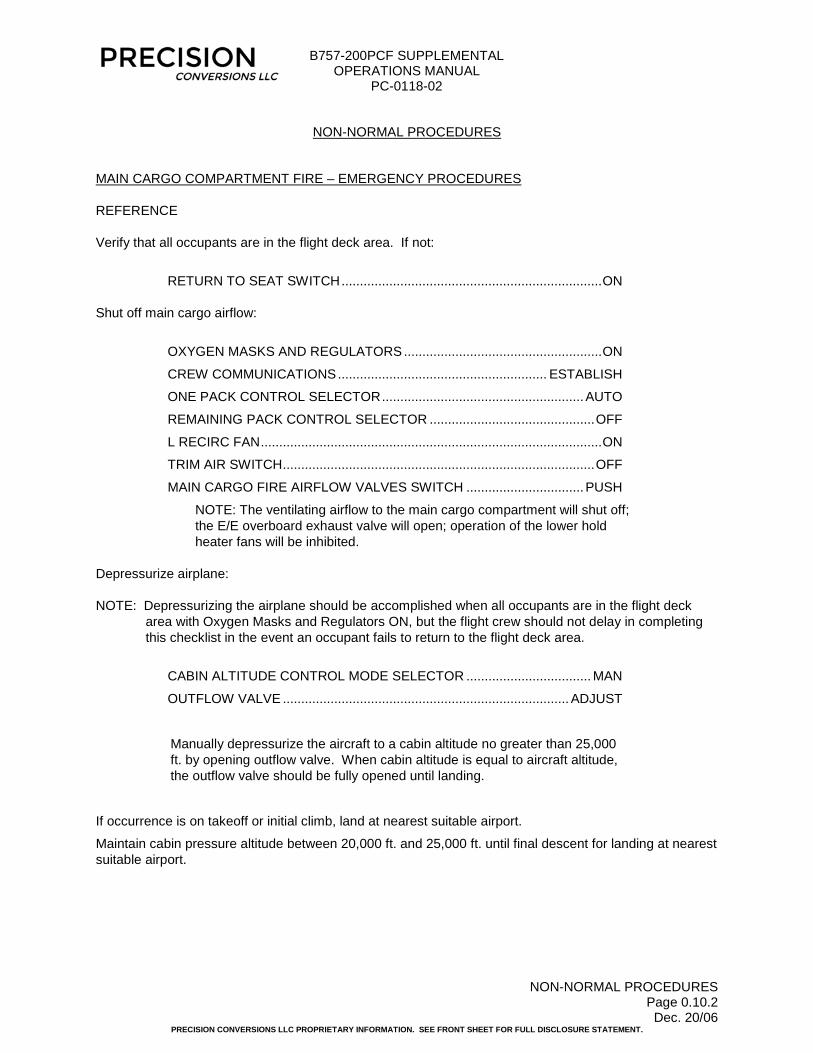
MAIN CARGO COMPARTMENT FIRE – EMERGENCY PROCEDURES REFERENCE Verify that all occupants are in the flight deck area. If not:
RETURN TO SEAT SWITCH ....................................................................... ON Shut off main cargo airflow:
OXYGEN MASKS AND REGULATORS ...................................................... ON
CREW COMMUNICATIONS ......................................................... ESTABLISH
ONE PACK CONTROL SELECTOR ....................................................... AUTO
REMAINING PACK CONTROL SELECTOR ............................................. OFF
L RECIRC FAN ............................................................................................. ON
TRIM AIR SWITCH ..................................................................................... OFF
MAIN CARGO FIRE AIRFLOW VALVES SWITCH ................................ PUSH
NOTE: The ventilating airflow to the main cargo compartment will shut off; the E/E overboard exhaust valve will open; operation of the lower hold heater fans will be inhibited.
Depressurize airplane: NOTE: Depressurizing the airplane should be accomplished when all occupants are in the flight deck
area with Oxygen Masks and Regulators ON, but the flight crew should not delay in completing this checklist in the event an occupant fails to return to the flight deck area.
CABIN ALTITUDE CONTROL MODE SELECTOR .................................. MAN
OUTFLOW VALVE .............................................................................. ADJUST
Manually depressurize the aircraft to a cabin altitude no greater than 25,000 ft. by opening outflow valve. When cabin altitude is equal to aircraft altitude, the outflow valve should be fully opened until landing.
If occurrence is on takeoff or initial climb, land at nearest suitable airport.
Maintain cabin pressure altitude between 20,000 ft. and 25,000 ft. until final descent for landing at nearest suitable airport.

B757-200PCF SUPPLEMENTAL OPERATIONS MANUAL
PC-0118-02
NON-NORMAL PROCEDURES Page 0.10.3 Dec. 20/06
PRECISION CONVERSIONS LLC PROPRIETARY INFORMATION. SEE FRONT SHEET FOR FULL DISCLOSURE STATEMENT.
MAIN CARGO DOOR INDICATION LIGHT CONDITION: The MAIN CARGO DOOR light illuminated indicates the main deck cargo door is not
closed and latched and locked. NOTE: The door is in a safe configuration as long as cabin pressurization is normal and no more than 1
of the 4 amber Cargo Door Status lights on the Main Cargo Door Control Panel is illuminated. If the pressurization is not normal, or more than 1 of the 4 amber Cargo Door Status lights on the Main Cargo Door Control Panel is illuminated:
RETURN TO SEAT SWITCH ....................................................................... ON
LANDING ALTITUDE SELECTOR ................................................. 9,500 FEET
If occurrence is on takeoff or initial climb:
Do not exceed 10,000 feet.
If occurrence is in climb, cruise, or descent:
Descend to lowest safe altitude or 14,000 feet, whichever is higher.

B757-200PCF SUPPLEMENTAL OPERATIONS MANUAL
PC-0118-02
CHAPTER 1 - TOC Page 1.0.1 May 30/10
PRECISION CONVERSIONS LLC PROPRIETARY INFORMATION. SEE FRONT SHEET FOR FULL DISCLOSURE STATEMENT.
CHAPTER 1 - AIRPLANE GENERAL, EMERGENCY EQUIPMENT, DOORS, WINDOWS
PAGE
TABLE OF CONTENTS .................................................................................................................... 1.0.1
PRINCIPAL DIMENSIONS ............................................................................................................... 1.10.1
FLIGHT DECK INSTRUMENT PANELS .......................................................................................... 1.20.1
CREW WARNINGS .......................................................................................................................... 1.30.1
LIGHTING ......................................................................................................................................... 1.40.1
DOORS ............................................................................................................................................. 1.50.1
INTRODUCTION ........................................................................................................................ 1.50.1
CREW ENTRY DOOR ................................................................................................................ 1.50.2
MAIN CARGO DOOR ................................................................................................................. 1.50.5
RIGID BARRIER SLIDING DOOR .............................................................................................. 1.50.9
FLIGHT DECK NO. 2 WINDOW RH ................................................................................................. 1.60.1
OXYGEN SYSTEM ........................................................................................................................... 1.70.1
EMERGENCY EQUIPMENT ............................................................................................................. 1.80.1
EMERGENCY EVACUATION ........................................................................................................... 1.90.1

B757-200PCF SUPPLEMENTAL OPERATIONS MANUAL
PC-0118-02
PRINCIPAL DIMENSIONS
Page 1.10.1 Feb. 15/12
PRECISION CONVERSIONS LLC PROPRIETARY INFORMATION. SEE FRONT SHEET FOR FULL DISCLOSURE STATEMENT.
EFFECTIVITY: ALL B757-200PCF
PRINCIPAL DIMENSIONS
The principal dimensions remain unchanged. The picture below shows the external configuration of the cargo aircraft. A new crew entry door at BS 317.5 is depicted, as well as the main cargo door at BS 550.0

B757-200PCF SUPPLEMENTAL OPERATIONS MANUAL
PC-0118-02
FLIGHT DECK INSTRUMENT PANELS
Page 1.20.1 Dec. 31/14
PRECISION CONVERSIONS LLC PROPRIETARY INFORMATION. SEE FRONT SHEET FOR FULL DISCLOSURE STATEMENT.
EFFECTIVITY: ALL B757-200PCF
FLIGHT DECK INSTRUMENT PANELS
Illustrations in this section show changes to flight deck instrument panels. LEFT OVERHEAD PANEL
Circled numbers refer to sections in this manual where additional information on the item may be found.

B757-200PCF SUPPLEMENTAL OPERATIONS MANUAL
PC-0118-02
FLIGHT DECK INSTRUMENT PANELS
Page 1.20.2 Dec. 31/14
PRECISION CONVERSIONS LLC PROPRIETARY INFORMATION. SEE FRONT SHEET FOR FULL DISCLOSURE STATEMENT.
EFFECTIVITY: ALL B757-200PCF
RIGHT OVERHEAD PANEL
Circled numbers refer to sections in this manual where additional information on the item may be found.

B757-200PCF SUPPLEMENTAL OPERATIONS MANUAL
PC-0118-02
FLIGHT DECK INSTRUMENT PANELS
Page 1.20.3 Dec. 31/14
PRECISION CONVERSIONS LLC PROPRIETARY INFORMATION. SEE FRONT SHEET FOR FULL DISCLOSURE STATEMENT.
EFFECTIVITY: ALL B757-200PCF
CENTER FORWARD PANEL
Circled numbers refer to sections in this manual where additional information on the item may be found.

B757-200PCF SUPPLEMENTAL OPERATIONS MANUAL
PC-0118-02
FLIGHT DECK INSTRUMENT PANELS
Page 1.20.4 Dec. 31/14
PRECISION CONVERSIONS LLC PROPRIETARY INFORMATION. SEE FRONT SHEET FOR FULL DISCLOSURE STATEMENT.
EFFECTIVITY: ALL B757-200PCF
RIGHT SIDEWALL, ACCESSORY PANEL Circled numbers refer to sections in this manual where additional information on the item may be found.
OVERWING EMERGENCY EXIT TEST: PLACARDED “DEACT” 2 PLACES

B757-200PCF SUPPLEMENTAL OPERATIONS MANUAL
PC-0118-02
CREW WARNINGS
Page 1.30.1 May 15/16
PRECISION CONVERSIONS LLC PROPRIETARY INFORMATION. SEE FRONT SHEET FOR FULL DISCLOSURE STATEMENT.
EFFECTIVITY: ALL B757-200PCF
CREW WARNINGS
CREW WARNING PANEL
Overhead Panel, P5 DON OXYGEN MASK Selector RETURN TO SEAT Selector The crew warning signs illuminate when the following conditions are satisfied: RETURN TO SEAT sign (AUTO selected):
• Landing gear not up and locked, or • Flap lever not up, or • Cabin altitude above 10,000 feet
DON OXYGEN MASK sign (AUTO selected):
• Cabin altitude above 14,000 feet When the DON OXYGEN MASK sign illuminates, selected main cargo compartment lights will flash. When the warning signs illuminate and extinguish, a chime sounds in the lavatory and a 5 second aural warning in the main cargo compartment. All crew signs can be controlled manually by positioning the respective selector to ON or OFF.
2
1
2
1

B757-200PCF SUPPLEMENTAL OPERATIONS MANUAL
PC-0118-02
LIGHTING
Page 1.40.1 Feb. 15/12
PRECISION CONVERSIONS LLC PROPRIETARY INFORMATION. SEE FRONT SHEET FOR FULL DISCLOSURE STATEMENT.
EFFECTIVITY: ALL B757-200PCF
LIGHTING
INTERIOR LIGHTING An incandescent dome light in the flight compartment ceiling panel illuminates the entry area. The entry area dome light is controlled by two three-way switches. One switch is installed on a panel located near the entry door, and the second switch is located on the P5 panel. The entry area dome light can be turned on or off from either location. The existing threshold step light is removed, and a new light is installed to identify the location of the step down in the flight compartment. The lavatory includes two lights: a general illumination light and a mirror light. With the door not fully closed, the lights are dim. When the door is fully closed and latched the lights are bright. Lights are installed in the ceiling panels of the main cargo compartment to provide general illumination either while the airplane is on the ground or in flight. The main cargo compartment lights are controlled with a switch located on the forward face of the cargo barrier near the sliding door to the main cargo compartment. CARGO DOOR FLOOD LIGHTS There are two flood light assemblies installed on the main deck cargo door inner skin. The ON/OFF switch is located on the Main Cargo Door Control Panel, which is located on the aft side of the BS 297 bulkhead. EMERGENCY LIGHTING Emergency lighting is controlled by the emergency lights switch located on the P5 panel. For general information regarding the Emergency Lighting system see OEM Operations. Interior Emergency Lighting
Interior emergency lighting consists of a general illumination dome light and an emergency exit sign located above the crew entry door.
Exterior Emergency Lighting
Exterior emergency lighting consists of lighting for both the crew entry door and the No. 2 right-hand flight deck window. These two lights provide emergency egress lighting.

B757-200PCF SUPPLEMENTAL OPERATIONS MANUAL
PC-0118-02
DOORS
Page 1.50.1 Jun. 27/05
PRECISION CONVERSIONS LLC PROPRIETARY INFORMATION. SEE FRONT SHEET FOR FULL DISCLOSURE STATEMENT.
EFFECTIVITY: ALL B757-200PCF
DOORS
FLIGHT DECK DOOR The flight deck door was removed as a result of the passenger to cargo conversion. In addition, the flight deck door indication switch located on the overhead panel was deactivated and covered with a blanking plate. ACCESS DOORS No changes affect this section. EMERGENCY EXIT DOORS All existing emergency exit doors are deactivated in the closed and locked position. See emergency equipment chapter for emergency exit procedures. ENTRY/SERVICE DOORS All existing passenger entry doors are either removed or are deactivated in the closed and locked position. Door warning systems for the deactivated/removed doors have been reinstalled to indicate these doors are always closed, latched, and locked. There is one crew entry door installed on the left side of the flight deck that is used to access the cockpit during normal operating conditions. The left hand door No. 1 indication system has been relocated from the removed L1 door to the crew entry door. All indications for Door L1 now refer to the crew entry door. EXTERIOR DOOR ANNUNCIATOR LIGHTS See section CREW ENTRY DOOR – CONTROLS AND INDICATORS for changes to the EXTERIOR DOOR ANNUNCIATOR LIGHTS (located on Overhead Panel, P5).

B757-200PCF SUPPLEMENTAL OPERATIONS MANUAL
PC-0118-02
DOORS
Page 1.50.2 May 15/16
PRECISION CONVERSIONS LLC PROPRIETARY INFORMATION. SEE FRONT SHEET FOR FULL DISCLOSURE STATEMENT.
EFFECTIVITY: ALL B757-200PCF
ENTRY DOORS
EMER DOORS
CARGO DOORS
ACCESS DOORS
CREW ENTRY DOOR – CONTROLS AND INDICATORS CREW ENTRY DOOR ANNUNCIATOR LIGHT
Overhead Panel, P5 ENTRY DOORS Light Illuminated (amber) – crew entry door is not closed, latched, and locked. EMER DOORS Light Emergency doors deactivated. See OEM Operations Manual.
1
1
4
2 3
2
4 3

B757-200PCF SUPPLEMENTAL OPERATIONS MANUAL
PC-0118-02
DOORS
Page 1.50.3 Jun. 27/05
PRECISION CONVERSIONS LLC PROPRIETARY INFORMATION. SEE FRONT SHEET FOR FULL DISCLOSURE STATEMENT.
EFFECTIVITY: ALL B757-200PCF
CREW ENTRY DOOR - FEATURES

B757-200PCF SUPPLEMENTAL OPERATIONS MANUAL
PC-0118-02
DOORS
Page 1.50.4 Jun. 27/05
PRECISION CONVERSIONS LLC PROPRIETARY INFORMATION. SEE FRONT SHEET FOR FULL DISCLOSURE STATEMENT.
EFFECTIVITY: ALL B757-200PCF
CREW ENTRY DOOR – DESCRIPTION
There is one crew entry door installed on the left side of the crew compartment that is used to access the cockpit during normal operating conditions. It is a fully inward opening plug-type door (initial opening movement inward) and is operable (open and close) from either inside or outside of the airplane (View A & B). The door has upper and lower latches to latch the door when closed. During normal operation, the door will open inward to its fully open position, under its own weight, and stop against a bumper on the cargo barrier. A latch mechanism located on the 9G barrier will lock the door in the open position (View C). Annunciator lights and EICAS messages have not been changed. However, Left hand door No. 1 now refers to the crew entry door, for door warning system. The ENTRY DOORS light on the overhead panel illuminates and the appropriate EICAS message appears if the crew entry door is not closed. Open Crew Entry Door From Inside: WARNING: Before the door is opened, be sure to secure the door with your body weight as the
door will open inward under its own weight.
• Push the aft side of the handle inboard slightly.
• Rotate the handle clockwise 90 degrees to the unlatched position.
• With the handle in the unlatched position, slowly allow the door to open under its own weight, while securing through the entire opening motion until door stops against bumper on the cargo barrier.
Open Crew Entry Door From Outside: WARNING: Before the door is opened, be sure to secure the door as the door will open inward
under its own weight.
• Push the forward end of the outer handle inboard slightly.
• Rotate the handle counterclockwise 90 degrees to the unlatched position.
• With the handle in the unlatched position, slowly step into the aircraft and allow the door to open under its own weight, while securing through the entire opening motion until door stops against bumper on cargo barrier.
Close Crew Entry Door:
• Before the door is closed, position the handles in the unlatched (vertical) position.
• Push (or pull) the door to the closed position until contact is made.
• Rotate handle into the latched (horizontal) position. In the latched position the outer handle should be flush with the outer door skin.

B757-200PCF SUPPLEMENTAL OPERATIONS MANUAL
PC-0118-02
DOORS
Page 1.50.5 Dec. 05/15
PRECISION CONVERSIONS LLC PROPRIETARY INFORMATION. SEE FRONT SHEET FOR FULL DISCLOSURE STATEMENT.
EFFECTIVITY: ALL B757-200PCF
MAIN CARGO DOOR – CONTROLS AND INDICATORS The electrical door indication system will directly indicate the door closed latched, and locked condition. To indicate the door position to the flight crew, a light in the flight deck will be located in front of the pilots. The light color will be red and the nomenclature will be MAIN CARGO DOOR. Warning lights on the control panel will indicate door position to the operator. MAIN CARGO DOOR CONTROL PANEL
Located on Partition, Adjacent to Crew Entry Door
MAIN CARGO DOOR Warning Light Illuminated (red) – main cargo door is not fully closed, latched, and locked. DOOR CONTROL Switch OPEN – commands the main cargo door to open when power is provided. CLOSE – commands the main cargo door to close when power is provided. Switch must be held OPEN or CLOSE, otherwise it will return to neutral position. Requires DOOR POWER ENABLE switch to be ON for this switch to function.
1
3
4
6
7 8
5
2
9
1
2

B757-200PCF SUPPLEMENTAL OPERATIONS MANUAL
PC-0118-02
DOORS
Page 1.50.6 Dec. 20/06
PRECISION CONVERSIONS LLC PROPRIETARY INFORMATION. SEE FRONT SHEET FOR FULL DISCLOSURE STATEMENT.
EFFECTIVITY: ALL B757-200PCF
MAIN
CARGO
DOOR
DOOR POWER ENABLE Switch ON – Supplies power to the main cargo door. OFF – Disconnects power to the main cargo door. Requires POWER MASTER CONTROL Switch to be ON for switch to function. FLOOD LIGHTS Switch ON – Turns main cargo door flood lights on. OFF – Turns main cargo door flood lights off. POWER MASTER CONTROL Guarded Switch ON – Supplies power to the MAIN CARGO DOOR CONTROL Panel. OFF – Disconnects power to the MAIN CARGO DOOR CONTROL Panel. VENT DOOR OPEN Light Illuminated (amber) – main cargo door vent doors not fully closed. NOT LOCKED Light Illuminated (amber) – main cargo door not fully locked. NOT LATCHED Light Illuminated (amber) – main cargo door not fully latched. NOT CLOSED Light Illuminated (amber) – main cargo door not fully closed. MAIN CARGO DOOR WARNING LIGHT
Center Forward Panel, P1-3 MAIN CARGO DOOR Switch Illuminated (red) – main cargo door not fully closed, latched, and locked. Pushing switch silences the main cargo door aural warning, but the switch remains illuminated.
3
4
5
6
7
8
9
1
1

B757-200PCF SUPPLEMENTAL OPERATIONS MANUAL
PC-0118-02
DOORS
Page 1.50.7 Jun. 27/05
PRECISION CONVERSIONS LLC PROPRIETARY INFORMATION. SEE FRONT SHEET FOR FULL DISCLOSURE STATEMENT.
EFFECTIVITY: ALL B757-200PCF
AURAL WARNING PANEL
Overhead Panel, P5 CARGO DOOR AURAL OFF Switch Illuminated (amber) – aural warning is disabled Main Cargo Door aural warnings can be disabled by either of the following actions:
1. Pressing the CARGO DOOR AURAL OFF switch on the overhead panel, P5. 2. Pressing the MAIN CARGO DOOR switch on the center panel, P1.
Main Cargo Door/Fire Aural Warning Speaker
1 2
1
2

B757-200PCF SUPPLEMENTAL OPERATIONS MANUAL
PC-0118-02
DOORS
Page 1.50.7A Oct. 22/07
PRECISION CONVERSIONS LLC PROPRIETARY INFORMATION. SEE FRONT SHEET FOR FULL DISCLOSURE STATEMENT.
EFFECTIVITY: ALL B757-200PCF INCORPORATING PC SERVICE BULLETIN 757-52-0006
AURAL WARNING PANEL
Overhead Panel, P5 CARGO DOOR AURAL OFF Switch Main Cargo Door/Fire Aural Warning Speaker Deactivation Placard Note: The Main Cargo Door Aural Warning is deactivated by the incorporation of this service bulletin.
1 2
1
2
3
3

B757-200PCF SUPPLEMENTAL OPERATIONS MANUAL
PC-0118-02
DOORS
Page 1.50.8 Nov. 15/16
PRECISION CONVERSIONS LLC PROPRIETARY INFORMATION. SEE FRONT SHEET FOR FULL DISCLOSURE STATEMENT.
EFFECTIVITY: ALL B757-200PCF
MAIN CARGO DOOR – DESCRIPTION
A hydraulically operated main deck cargo door is installed in the left side of the airplane, forward of the wing. The door is an outward opening door whose initial opening movement is not inward. The cargo door opens to a canopy or a fully open position. The main cargo door will be controlled from a panel on the aft face of the bulkhead at BS 297. Operate the door as follows:
WARNING: Power master control switch must be OFF and all lights must be extinguished prior to any aircraft ground or in-flight operations.
CAUTION: DO NOT OPEN OR OPERATE THE DOOR IF THE ACTUAL OR ANTICIPATED WIND VELOCITY OR GUST EXCEEDS THE LIMITS SHOWN BELOW. SEVERE STRUCTURAL DAMAGE TO THE DOOR AND/OR THE AIRPLANE MAY RESULT.
Configuration Door Position (Note 1) Wind/Gust Limit (Note 2)
Airplanes 029 onwards.
Airplanes 001-028 incorporating SB PC-757-52-0018: 001, 008, 010, 011, 012, 015, 017, 019, 020, 022, 023, 027, 028
Up to Canopy 45 knots
Above Canopy 25 knots
Airplanes 001-028 NOT incorporating SB PC-757-52-0018: 002, 003, 004, 005, 006, 007, 009, 013, 014, 016, 018, 021, 024, 025, 026
Up to Canopy 45 knots
Above Canopy NO WIND ALLOWED (0 knots)
Note: 1. “Canopy” is defined as a door position where an imaginary “horizontal” line between the door hinge and lower edge is formed parallel to the ground +/- 20 degrees.
2. The airplane may be positioned in any orientation with respect to the wind direction.
To open door:
• Place the POWER MASTER CONTROL switch in the ON position • Place and hold the DOOR POWER ENABLE switch in the ON position • Place and hold the DOOR CONTROL switch in OPEN position • Release the open switch when the door is in the desired position. Verify all lights are illuminated.
NOTE: THE DOOR MAY BE LEFT IN ANY OPEN POSITION. HOWEVER, TO MINIMIZE THE POTENTIAL FOR STRUCTURAL DAMAGE DUE TO WIND, THE DOOR SHOULD BE LEFT IN THE CANOPY (HORIZONTAL) POSITION.
To close door:
• Place the POWER MASTER CONTROL switch in the ON position • Place and hold the DOOR POWER ENABLE switch in the ON position • Place and hold the DOOR CONTROL switch in CLOSED position • Verify all lights are extinguished when the door is in fully latched and locked position

B757-200PCF SUPPLEMENTAL OPERATIONS MANUAL
PC-0118-02
DOORS
Page 1.50.9 Dec. 31/14
PRECISION CONVERSIONS LLC PROPRIETARY INFORMATION. SEE FRONT SHEET FOR FULL DISCLOSURE STATEMENT.
EFFECTIVITY: ALL B757-200PCF
If the Door Indication System is inoperative and the Minimum Equipment List permits operation of the airplane with this equipment inoperative, the following maintenance procedures may be used to verify the main cargo door is closed, latched, and locked:
• Verify the main deck cargo door is closed and faired with the surrounding structure. • Verify both vent doors are closed and faired with the cargo door. • Check the eight viewports along the lower edge of the main cargo door to verify the lock pins
have engaged the latches and are in the locked position.
NOTES: 1. External check requires an adequate means, such as a hydraulic lift, to complete the visual
verifications. 2. Under certain conditions, a flashlight or equivalent lighting source is required. 3. Under certain conditions, use of Plexiglas cleaner may be required to clean the external view
ports.

B757-200PCF SUPPLEMENTAL OPERATIONS MANUAL
PC-0118-02
DOORS
Page 1.50.10 Jun. 27/05
PRECISION CONVERSIONS LLC PROPRIETARY INFORMATION. SEE FRONT SHEET FOR FULL DISCLOSURE STATEMENT.
EFFECTIVITY: ALL B757-200PCF
RIGID BARRIER SLIDING DOOR - FEATURES

B757-200PCF SUPPLEMENTAL OPERATIONS MANUAL
PC-0118-02
DOORS
Page 1.50.11 Jun. 27/05
PRECISION CONVERSIONS LLC PROPRIETARY INFORMATION. SEE FRONT SHEET FOR FULL DISCLOSURE STATEMENT.
EFFECTIVITY: ALL B757-200PCF
RIGID BARRIER SLIDING DOOR – DESCRIPTION
To protect the crew if there is an emergency landing, a rigid cargo barrier is installed to restrain cargo. The cargo barrier will also act as a smoke barrier in the event of a fire in the main deck cargo compartment. The rigid cargo barrier has a sliding doorway for entry into the Class E cargo compartment. The sliding door is located on the aft, left hand side of the barrier. A spring loaded retractable plunger is provided to secure the sliding door in the closed position.

B757-200PCF SUPPLEMENTAL OPERATIONS MANUAL
PC-0118-02
FLIGHT DECK NO. 2 WINDOW RH
Page 1.60.1 May 30/08
PRECISION CONVERSIONS LLC PROPRIETARY INFORMATION. SEE FRONT SHEET FOR FULL DISCLOSURE STATEMENT.
EFFECTIVITY: ALL B757-200PCF
FLIGHT DECK NO. 2 WINDOW RH – DESCRIPTION The No.2 right-hand side (RHS) flight deck window has been modified by installing an exterior handle. Pulling the external handle outward unlocks and unlatches the window. Rotating the external handle clockwise opens the window, while rotating the handle counter-clockwise closes the window. Pushing the handle back in to its stowed position does not latch the window. Latching the window must still be done from inside the aircraft. The window is opened and closed from inside the flight deck compartment in the same manner as the passenger aircraft with the exception that the push button on the top of the internal latch handle no longer locks the latch handle. This is by design to allow external opening of the window. See OEM Operations Manual for additional information.

B757-200PCF SUPPLEMENTAL OPERATIONS MANUAL
PC-0118-02
OXYGEN SYSTEM
Page 1.70.1 Jan. 15/18
PRECISION CONVERSIONS LLC PROPRIETARY INFORMATION. SEE FRONT SHEET FOR FULL DISCLOSURE STATEMENT.
EFFECTIVITY: ALL B757-200PCF
OXYGEN SYSTEM – DESCRIPTION Oxygen system for the flight crew is unchanged from the passenger aircraft, except passenger aircraft featuring 76 cu ft crew oxygen cylinders are upgraded to 115 cu ft. cylinder.
Airplanes incorporating Precision Conversions Service Bulletin PC-757-35-0005:
Two 115 cu ft. cylinders are installed. A Voltage Averaging Module (VAM) is installed to average the pressure transducer output signals from the two bottles for EICAS. The EICAS message indication is unaltered, but the reporting is of the average system pressure, not the individual cylinder pressures.
Two additional oxygen masks/regulators are installed for use by the supernumerary seat occupants. The masks/regulators operate in the same manner as the crew masks/regulators. The only notable difference is the new masks do not have microphones. All oxygen masks/regulators, crew and supernumerary, use the existing oxygen supply and indication system. For additional information see OEM operations manual.

B757-200PCF SUPPLEMENTAL OPERATIONS MANUAL
PC-0118-02
OXYGEN SYSTEM
Page 1.70.2 Jan. 15/18
PRECISION CONVERSIONS LLC PROPRIETARY INFORMATION. SEE FRONT SHEET FOR FULL DISCLOSURE STATEMENT.
EFFECTIVITY: ALL B757-200PCF
OXYGEN SYSTEM – DISPATCH PRESSURES
The following table shows the required oxygen cylinder dispatch pressures for a maximum of 6 occupants on oxygen from 30 to 180 minutes.
Required Pressure (psi) for one 115 Cu Ft Cylinder, P/N 801307-00 (Effectivity: Standard configuration, SB PC-757-35-0005 not installed)
No. of Crew Using
Oxygen
Oxygen Required for Level off at 25,000 ft (psi)
Total Time On 100% Oxygen (Mins) at 70 deg. F 30 60 90 120 150 180
2 450 673 895 1117 1340 1562 3 626 959 1293 1626 — — 4 801 1246 1690 — — — 5 976 1532 — — — — 6 1151 1818 — — — —
MAX CYLINDER PRESSURE: 1850 PSI
Required Indicated Pressure (psi) for two 115 Cu Ft Cylinders, P/N 801307-00 (Effectivity: Aircraft with SB PC-757-35-0005 installed)
No. of Crew Using
Oxygen
Oxygen Required for Level off at 25,000 ft (psi)
Total Time On 100% Oxygen (Mins) at 70 deg. F 30 60 90 120 150 180
2 274 384 495 605 715 825 3 361 526 692 857 1022 1188 4 448 668 889 1109 1329 1550 5 535 810 1086 1361 1637 — 6 622 952 1283 1613 — —
MAX CYLINDER PRESSURE: 1850 PSI
B757-200PCF SUPPLEMENTAL OPERATIONS MANUAL
PC-0118-02
EMERGENCY EQUIPMENT
Page 1.80.1 May 15/16
PRECISION CONVERSIONS LLC PROPRIETARY INFORMATION. SEE FRONT SHEET FOR FULL DISCLOSURE STATEMENT.
EFFECTIVITY: ALL B757-200PCF
EMERGENCY EQUIPMENT
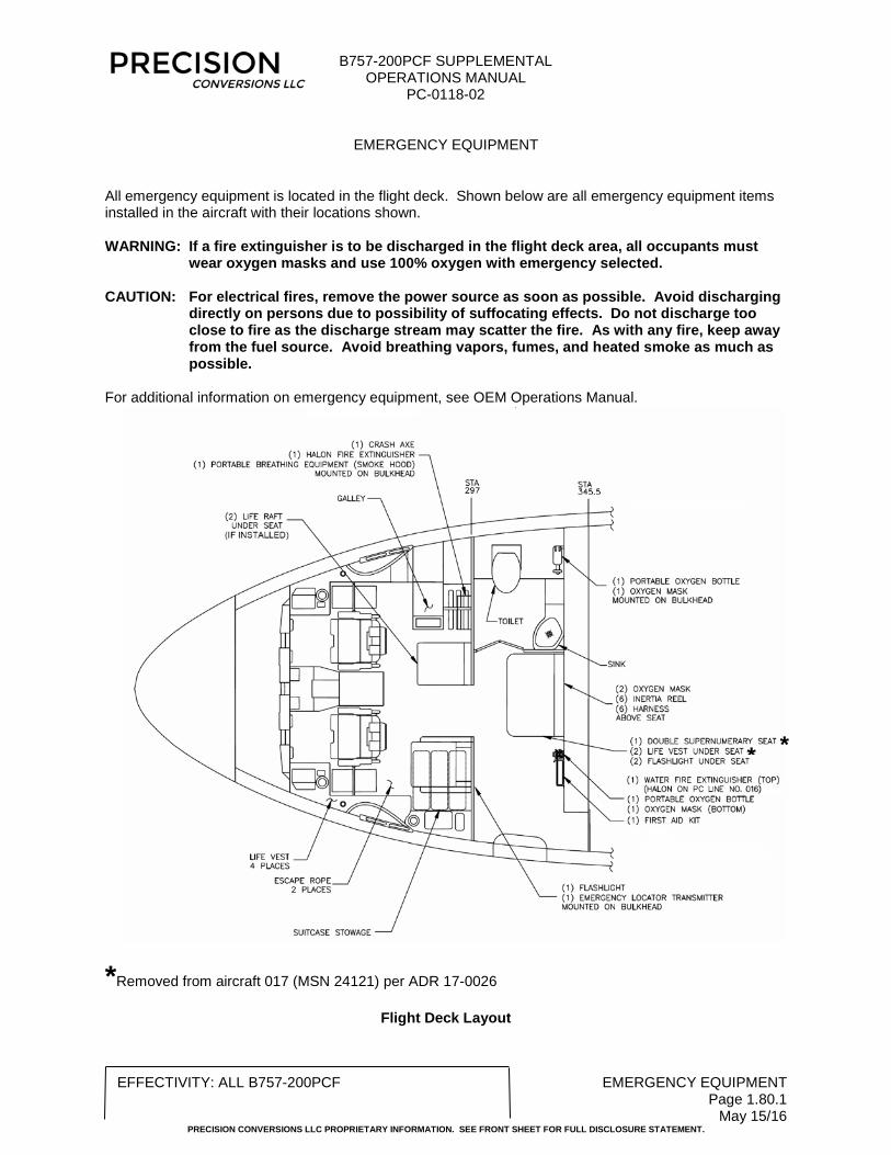
All emergency equipment is located in the flight deck. Shown below are all emergency equipment items installed in the aircraft with their locations shown. WARNING: If a fire extinguisher is to be discharged in the flight deck area, all occupants must
wear oxygen masks and use 100% oxygen with emergency selected. CAUTION: For electrical fires, remove the power source as soon as possible. Avoid discharging
directly on persons due to possibility of suffocating effects. Do not discharge too close to fire as the discharge stream may scatter the fire. As with any fire, keep away from the fuel source. Avoid breathing vapors, fumes, and heated smoke as much as possible.
For additional information on emergency equipment, see OEM Operations Manual.
*Removed from aircraft 017 (MSN 24121) per ADR 17-0026
Flight Deck Layout
* *

B757-200PCF SUPPLEMENTAL OPERATIONS MANUAL
PC-0118-02
EMERGENCY EQUIPMENT
Page 1.80.2 Jan. 15/18
PRECISION CONVERSIONS LLC PROPRIETARY INFORMATION. SEE FRONT SHEET FOR FULL DISCLOSURE STATEMENT.
EFFECTIVITY: 048, 050, 051, 057, 058, 060–065, 068, 070, 072, 077, 080-082, 088, 091
EMERGENCY EQUIPMENT
All emergency equipment is located in the flight deck. Shown below are all emergency equipment items installed in the aircraft with their locations shown. WARNING: If a fire extinguisher is to be discharged in the flight deck area, all occupants must
wear oxygen masks and use 100% oxygen with emergency selected. CAUTION: For electrical fires, remove the power source as soon as possible. Avoid discharging
directly on persons due to possibility of suffocating effects. Do not discharge too close to fire as the discharge stream may scatter the fire. As with any fire, keep away from the fuel source. Avoid breathing vapors, fumes, and heated smoke as much as possible.
For additional information on emergency equipment, see OEM Operations Manual.
Flight Deck Layout

B757-200PCF SUPPLEMENTAL OPERATIONS MANUAL
PC-0118-02
EMERGENCY EVACUATION
Page 1.90.1 Dec. 20/06
PRECISION CONVERSIONS LLC PROPRIETARY INFORMATION. SEE FRONT SHEET FOR FULL DISCLOSURE STATEMENT.
EFFECTIVITY: ALL B757-200PCF
EMERGENCY EVACUATION
EMERGENCY EGRESS Emergency egress from the flight deck can be done using both escape ropes and inertia reels. The procedures to use the emergency escape ropes are unchanged from the passenger aircraft and can be found in the OEM Operations Manual. CREW ENTRY DOOR EMERGENCY EGRESS If the crew entry door must be used for emergency evacuation, exit in accordance with the following illustration.

B757-200PCF SUPPLEMENTAL OPERATIONS MANUAL
PC-0118-02
CHAPTER 2 – TOC
Page 2.0.1 Oct. 22/07
PRECISION CONVERSIONS LLC PROPRIETARY INFORMATION. SEE FRONT SHEET FOR FULL DISCLOSURE STATEMENT.
EFFECTIVITY: ALL B757-200PCF
CHAPTER 2 - AIR CONDITIONING AND PRESSURIZATION
PAGE
TABLE OF CONTENTS .................................................................................................................... 2.0.1
SYSTEM DESCRIPTION .................................................................................................................. 2.10.1
TEMPERATURE CONTROL SCHEMATIC ...................................................................................... 2.10.2
CONDITIONED AIR DISTRIBUTION SCHEMATIC ......................................................................... 2.10.3

B757-200PCF SUPPLEMENTAL OPERATIONS MANUAL
PC-0118-02
AIR CONDITIONING AND PRESSURIZATION
Page 2.10.1 Dec. 20/06
PRECISION CONVERSIONS LLC PROPRIETARY INFORMATION. SEE FRONT SHEET FOR FULL DISCLOSURE STATEMENT.
EFFECTIVITY: ALL B757-200PCF
AIR CONDITIONING AND PRESSURIZATION - DESCRIPTION
Several changes have been made to the air conditioning system, due to the cargo conversion. However, few of these changes affect the control of the system. The right recirculation system has been deactivated. This was done in a manner to prevent the a/c packs from entering high flow mode, as would normally be the case with the right recirculation system shut off. The right recirculation fan switch, located on the Air Conditioning Control Module on the overhead panel, has been placarded DEACT. Airflow valves are installed in the event of a main cargo compartment fire. The airflow valves shut off airflow to the main cargo compartment; however, air will continue to be supplied to the flight deck. A positive air pressure differential will be maintained between the flight deck and the main cargo compartment to prevent smoke from entering the flight deck. The valves are controllable from the flight deck. See CHAPTER 7, FIRE PROTECTION, for information and operation of the airflow valves.

B757-200PCF SUPPLEMENTAL OPERATIONS MANUAL
PC-0118-02
AIR CONDITIONING AND PRESSURIZATION
Page 2.10.2 Dec. 20/06
PRECISION CONVERSIONS LLC PROPRIETARY INFORMATION. SEE FRONT SHEET FOR FULL DISCLOSURE STATEMENT.
EFFECTIVITY: ALL B757-200PCF
AIR CONDITIONING AND PRESSURIZATION
TEMPERATURE CONTROL SCHEMATIC

B757-200PCF SUPPLEMENTAL OPERATIONS MANUAL
PC-0118-02
AIR CONDITIONING AND PRESSURIZATION
Page 2.10.3 Dec. 20/06
PRECISION CONVERSIONS LLC PROPRIETARY INFORMATION. SEE FRONT SHEET FOR FULL DISCLOSURE STATEMENT.
EFFECTIVITY: ALL B757-200PCF
AIR CONDITIONING AND PRESSURIZATION
CONDITIONED AIR DISTRIBUTION SCHEMATIC

B757-200PCF SUPPLEMENTAL OPERATIONS MANUAL
PC-0118-02
CHAPTER 7 - TOC
Page 7.0.1 Oct. 22/07
PRECISION CONVERSIONS LLC PROPRIETARY INFORMATION. SEE FRONT SHEET FOR FULL DISCLOSURE STATEMENT.
EFFECTIVITY: ALL B757-200PCF
CHAPTER 7 - FIRE PROTECTION - MAIN CARGO COMPARTMENT
PAGE
TABLE OF CONTENTS .................................................................................................................... 7.0.1
MAIN CARGO COMPARTMENT FIRE PROTECTION .................................................................... 7.10.1
CONTROLS AND INDICATORS ................................................................................................ 7.10.1
SYSTEM DESCRIPTION ........................................................................................................... 7.10.3
SMOKE DETECTION TEST ....................................................................................................... 7.10.4
FIRE DETECTION SCHEMATIC ................................................................................................ 7.10.5

B757-200PCF SUPPLEMENTAL OPERATIONS MANUAL
PC-0118-02
FIRE PROTECTION
Page 7.10.1 May 30/10
PRECISION CONVERSIONS LLC PROPRIETARY INFORMATION. SEE FRONT SHEET FOR FULL DISCLOSURE STATEMENT.
EFFECTIVITY: ALL B757-200PCF
MAINFIRE
FWD AFT
VALVECLOSED
FAULT AIRFLOW VALVES
MAIN CARGO FIRE
VALVECLOSED
CLOSE
CARGO
TEST
MAIN CARGO COMPARTMENT FIRE PROTECTION – CONTROLS AND INDICATORS
CARGO FIRE FLIGHT DECK UNIT (CFFU)
Overhead Panel P5 MAIN FIRE Light Illuminated (red) – a main cargo compartment fire is detected. FAULT Light Illuminated (amber) – a fault has been detected during the test sequence. TEST Switch Press to initiate test sequence for main cargo compartment smoke detection system. VALVE CLOSED Lights Illuminated (white) – airflow valve is closed to corresponding zone in main cargo compartment. AIRFLOW VALVES Close Switch CARGO Light Illuminated (red) – a main cargo compartment fire is detected. CLOSE Light Illuminated (white) – both airflow valves are closed. Push to close AIRFLOW Valve –
• Closes both airflow valves • CLOSE Illuminates (white)
Push button a second time to open airflow valves.
1
2
3
4
5
1
2
4
3
5

B757-200PCF SUPPLEMENTAL OPERATIONS MANUAL
PC-0118-02
FIRE PROTECTION
Page 7.10.2 May 30/10
PRECISION CONVERSIONS LLC PROPRIETARY INFORMATION. SEE FRONT SHEET FOR FULL DISCLOSURE STATEMENT.
EFFECTIVITY: ALL B757-200PCF
FIRE WARNING LIGHT The Fire Warning light is located on the center forward panel, P1-3. In addition to indicating fires as described in the OEM Operating Handbook, this indicator illuminates red when smoke is detected in the main cargo compartment. MASTER WARNING LIGHTS Two Master Warning lights are located on the glareshield. In addition to indicating fires as described in the OEM Operating Handbook, these indicators illuminate when smoke is detected in the main cargo compartment. Depressing either of these lights silences the fire detection aural warning.

B757-200PCF SUPPLEMENTAL OPERATIONS MANUAL
PC-0118-02
FIRE PROTECTION
Page 7.10.3 Jun. 27/05
PRECISION CONVERSIONS LLC PROPRIETARY INFORMATION. SEE FRONT SHEET FOR FULL DISCLOSURE STATEMENT.
EFFECTIVITY: ALL B757-200PCF
MAIN CARGO COMPARTMENT FIRE PROTECTION – DESCRIPTION
The Fire Detection System (FiDS) is a two-loop smoke detection system that has been installed to detect smoke in the main cargo compartment. Airflow valves have also been installed to shut off air to the main cargo compartment to help fire suppression. The system includes a Cargo Fire Maintenance Unit (CFMU), located in the forward EE bay. The CFMU is responsible for monitoring each alarm, identifying false alarms, and passing on alarm information to the Cargo Fire Flight Deck Unit (CFFU). The CFFU is mounted in the overhead panel P5 and provides control and indication of the Fire Detection system. When a main cargo compartment fire is detected, the flight crew will be alerted by both aural and visual alerts. MAIN CARGO COMPARTMENT SMOKE DETECTION There are two detector loops installed in the main cargo compartment to provide smoke detection. The loops are attached to 17 smoke detectors installed in the ceiling of the main cargo compartment. The FAULT light illuminates on the CFFU panel to indicate failure of the smoke detection system. The MAIN FIRE light illuminates on the CFFU panel to indicate main deck smoke has been detected. The flight crew will be alerted by both aural and visual alerts. If a main cargo compartment alarm condition occurs, the flight crew will be alerted within 60 seconds. MAIN CARGO COMPARTMENT FIRE WARNING The indications of a main cargo compartment smoke warning are:
• The red MAIN FIRE light on CFFU, which is on pilot’s overhead panel P5, illuminates. • The red CARGO light on CFFU switch light (P5) illuminates. • The red master WARNING lights on P7 (pilots glare shield) comes on. • The red FIRE light on P1-3 (pilot’s instrument panel) comes on. • The aural warning panel on P5 sounds.
MAIN CARGO COMPARTMENT FIRE SUPPRESSION If a cargo fire is detected and the flight deck commands closure through the CFFU Airflow Valve switch, both valves will close. The airflow valves may be operated in two different methods: manually using the AIRFLOW VALVES switch located on the CFFU or manually at the valve.

B757-200PCF SUPPLEMENTAL OPERATIONS MANUAL
PC-0118-02
FIRE PROTECTION
Page 7.10.4 Jun. 27/05
PRECISION CONVERSIONS LLC PROPRIETARY INFORMATION. SEE FRONT SHEET FOR FULL DISCLOSURE STATEMENT.
EFFECTIVITY: ALL B757-200PCF
MAIN CARGO COMPARTMENT FIRE PROTECTION – SMOKE DETECTION TEST
CARGO FIRE FLIGHT DECK UNIT (CFFU) Self-test features on both the maintenance unit and the flight deck unit verify system functionality. The system test can be initiated from the flight deck by depressing a single test switch on the flight deck unit. The system test includes testing of (1) all smoke detectors, in both loops, and (2) all smoke alarm indicators on the flight deck. If the FAULT light illuminates on the CFFU after depressing and releasing the TEST switch, the aircraft is non-dispatchable. A non-dispatchable condition is a result of both detectors in a zone being faulty or one of the power busses being out. The following test verifies main cargo smoke detection system functionality using the system self-test feature.
1. Supply electrical power. 2. Press and hold the TEST pushbutton on the face of the CFFU.
A. Verify that these main cargo fire indications occur:
(1) MAIN FIRE light (red) illuminates on CFFU. (2) CARGO light (red) illuminates on CFFU. (3) FIRE Warning light (red) illuminates on center forward panel. (4) Master WARNING lights (x2, red) illuminate on glareshield panel. (5) Main cargo fire aural warning is heard.
B. Verify that these indicators on the CFFU also illuminate.
(1) FAULT (amber). (2) VALVE CLOSED (x2, white). (3) CLOSE (white) on switchlight.
3. Release the TEST pushbutton.
A. Verify that these indications extinguish/stop.
(1) MAIN FIRE light on CFFU. (2) CARGO light on CFFU. (3) FIRE Warning light on center forward panel. (4) Master WARNING lights (x2) on glareshield panel. (5) Main cargo fire aural warning.
B. Verify that these indicators on the CFFU also extinguish.
(1) FAULT (amber). (2) VALVE CLOSED (x2, white). (3) CLOSE (white) on switchlight.
B757-200PCF SUPPLEMENTAL OPERATIONS MANUAL
PC-0118-02
FIRE PROTECTION
Page 7.10.5 Dec. 20/06
PRECISION CONVERSIONS LLC PROPRIETARY INFORMATION. SEE FRONT SHEET FOR FULL DISCLOSURE STATEMENT.
EFFECTIVITY: ALL B757-200PCF
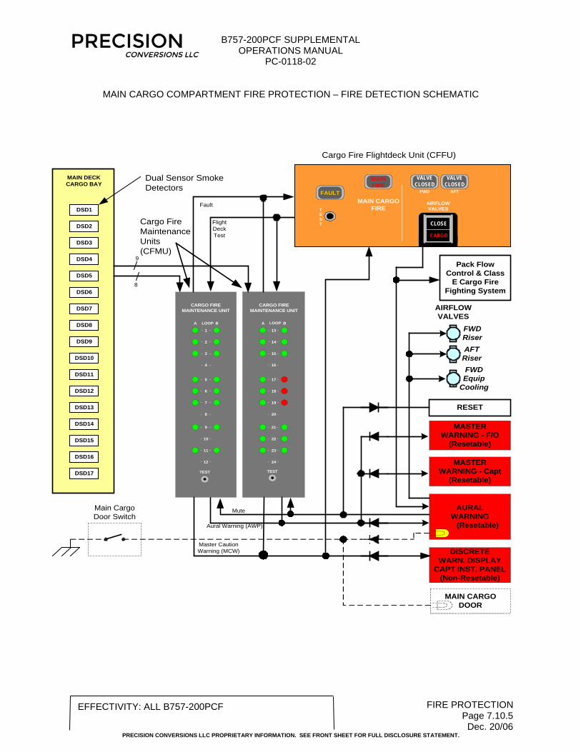
MAIN CARGO COMPARTMENT FIRE PROTECTION – FIRE DETECTION SCHEMATIC
Cargo Fire Maintenance Units(CFMU)
MASTERWARNING - F/O
(Resetable)
Cargo Fire Flightdeck Unit (CFFU)
MAIN DECKCARGO BAY
DSD2
DSD4
DSD6
DSD8
DSD10
DSD12
DSD14
DSD16
RESET
Dual Sensor Smoke Detectors
DSD1
DSD3
DSD5
DSD7
DSD9
DSD11
DSD13
DSD15
DSD17
8
9
A B
13
TEST
14
15
24
21
16
20
19
18
17
23
22
LOOPA B
1
TEST
2
3
12
9
4
8
7
6
5
11
10
LOOP
AIRFLOW VALVES
FWD RiserAFT Riser
DISCRETEWARN. DISPLAY
CAPT INST. PANEL(Non-Resetable)
MASTERWARNING - Capt
(Resetable)
CARGO FIREMAINTENANCE UNIT
CARGO FIREMAINTENANCE UNIT
Fault
Flight Deck Test
Aural Warning (AWP)
Master Caution Warning (MCW)
Mute
AIRFLOWVALVES
MAIN CARGOFIRE
FWD AFTFAULT
VALVE CLOSED
MAIN FIRE
VALVE CLOSED
TEST CLOSE
CARGO
Main Cargo Door Switch
MAIN CARGO DOOR
AURALWARNING
(Resetable)
Pack Flow Control & Class
E Cargo Fire Fighting System
FWD Equip
Cooling
Related Documents