Road Planning and Design Manual Edition 2: Volume 3 Supplement to Austroads Guide to Road Design Part 1: Objectives of Road Design November 2021

Welcome message from author
This document is posted to help you gain knowledge. Please leave a comment to let me know what you think about it! Share it to your friends and learn new things together.
Transcript
Road Planning and Design Manual Edition 2: Volume 3 Supplement to Austroads Guide to Road Design Part 1: Objectives of Road Design November 2021
Road Planning and Design Manual – Edition 2: Volume 3, Transport and Main Roads, November 2021
Copyright © The State of Queensland (Department of Transport and Main Roads) 2021. Licence
This work is licensed by the State of Queensland (Department of Transport and Main Roads) under a Creative Commons Attribution (CC BY) 4.0 International licence. CC BY licence summary statement In essence, you are free to copy, communicate and adapt this work, as long as you attribute the work to the State of Queensland (Department of Transport and Main Roads). To view a copy of this licence, visit: https://creativecommons.org/licenses/by/4.0/ Translating and interpreting assistance
The Queensland Government is committed to providing accessible services to Queenslanders from all cultural and linguistic backgrounds. If you have difficulty understanding this publication and need a translator, please call the Translating and Interpreting Service (TIS National) on 13 14 50 and ask them to telephone the Queensland Department of Transport and Main Roads on 13 74 68.
Disclaimer While every care has been taken in preparing this publication, the State of Queensland accepts no responsibility for decisions or actions taken as a result of any data, information, statement or advice, expressed or implied, contained within. To the best of our knowledge, the content was correct at the time of publishing. Feedback Please send your feedback regarding this document to: [email protected]
Road Planning and Design Manual – Edition 2: Volume 3, Transport and Main Roads, November 2021 i
Relationship with Austroads Guide to Road Design – Part 1 (2021)
The Department of Transport and Main Roads has, in principle, agreed to adopt the standards published in the Austroads Guide to Road Design (2021) Part 1: Objectives of Road Design.
When reference is made to other parts of the Austroads Guide to Road Design, Austroads Guide to Traffic Management or the Austroads Guide to Road Safety, the reader should also refer to Transport and Main Roads related manuals:
• Road Planning and Design Manual (RPDM), and
• Traffic and Road Use Management Manual.
Where a section does not appear in the body of this supplement, the Austroads Guide to Road Design – Part 1 criteria is accepted unamended.
This supplement:
1. has precedence over the Austroads Guide to Road Design – Part 1 when applied in Queensland
2. details additional requirements, including accepted with amendments (additions or differences), new or not accepted, and
3. has the same structure (section numbering, headings and contents) as Austroads Guide to Road Design – Part 1.
The following table summarises the relationship between the Austroads Guide to Road Design – Part 1 and this supplement using the following criteria:
Accepted Where a section does not appear in the body of this supplement, the Austroads Guide to Road Design – Part 1 is accepted.
Accepted with Amendments
Part or all of the section has been accepted with additions and/or differences.
New There is no equivalent section in the Austroads Guide.
Not accepted The section of the Austroads Guide is not accepted.
Austroads Guide to Road Design – Part 1 RPDM relationship
1 Scope of the Guide to Road Design
1.1 Introduction Accepted with amendments
1.2 Guide to Road Design Purpose Accepted with amendments
1.3 Application of the Guide to Road Design Accepted
1.4 Parts of the Guide to Road Design Accepted
1.5 Links to Other Guides Accepted
1.6 Jurisdictional Supplements Accepted
2 Road Design Across the Transport Management System
2.1 Road Management Phase Process Accepted with amendments
2.2 Network Considerations and Outcomes Accepted with amendments
2.3 Multi-Modal Considerations Accepted with amendments
Road Planning and Design Manual – Edition 2: Volume 3, Transport and Main Roads, November 2021 ii
Austroads Guide to Road Design – Part 1 RPDM relationship
3 Principles and Objectives of Road Design
3.1 Definition of Road Design Accepted with amendments
3.2 Road Design Principles Accepted with amendments
3.3 Objectives of Road Design Accepted
3.4 Geometric Consistency Accepted with amendments
3.5 Future Technology Considerations Accepted
3.6 Performance-based Design Accepted
3.7 Community Expectations Accepted
4 Road Design Application
4.1 Road Characteristics and Use Accepted with amendments
4.2 Phases of Design Accepted
4.3 Context-sensitive Design Accepted
4.4 The Design Domain Accepted with amendments
4.5 Design Exception Process Accepted with amendments
4.6 Design and Legal Liability Accepted with amendments
4.7 Coordination of Disciplines Accepted with amendments
4.8 Delivery Considerations Accepted
5 The Road Design Process
5.1 General Accepted with amendments
5.2 Design Process Accepted with amendments
References
References Accepted with amendments
Appendices
Appendix A Process and Documentation Accepted with amendments
Appendix B Geotechnical Investigations and Design Accepted with amendments
Appendix C EDD and Design Exception Report New
Road Planning and Design Manual – Edition 2: Volume 3, Transport and Main Roads, November 2021 iii
Contents
1 Scope of the guide to road design .............................................................................................. 1
1.1 Introduction ..................................................................................................................................... 1
1.2 Guide to road design purpose ........................................................................................................ 1
2 Road design across the transport management system ......................................................... 2
2.1 Road management phase process ................................................................................................. 2 2.1.1 Road Planning ............................................................................................................... 2
2.2 Network considerations and outcomes ........................................................................................... 2 2.2.3 Designing for safety ....................................................................................................... 2
2.3 Multi-modal considerations ............................................................................................................. 4 2.3.3 Provision for cyclists and pedestrians ........................................................................... 4 2.3.5 Disability access ............................................................................................................ 4
3 Principles and objectives of road design ................................................................................... 5
3.1 Definition of road design ................................................................................................................. 5
3.2 Road design principles ................................................................................................................... 8
3.4 Geometric consistency ................................................................................................................... 9 3.4.1 General .......................................................................................................................... 9 3.4.4 Driver workload ............................................................................................................ 10
4 Road design application ............................................................................................................ 11
4.1 Road characteristics and use ....................................................................................................... 11 4.1.1 Functional classification and use ................................................................................. 11 4.1.2 Factors that influence design standards ..................................................................... 13 4.1.3 Speed parameters ....................................................................................................... 13
4.4 The design domain ....................................................................................................................... 13 4.4.1 Normal design domain ................................................................................................ 13 4.4.2 Extended design domain ............................................................................................. 13 4.4.4 Road design classes ................................................................................................... 14
4.5 Design exception process ............................................................................................................. 19 4.5.1 Design exceptions ....................................................................................................... 19 4.5.2 Innovative and emerging treatments ........................................................................... 19 4.5.4 Mitigation strategies for design exceptions ................................................................. 19
4.6 Design and legal liability ............................................................................................................... 22 4.6.1 Legal liability ................................................................................................................ 22 Opportunity to innovate ................................................................................................................. 22
4.7 Coordination of disciplines ............................................................................................................ 23
5 The road design process ........................................................................................................... 23
5.1 General ......................................................................................................................................... 23
5.2 Design report ................................................................................................................................ 23 5.2.1 Design report content .................................................................................................. 23
References ........................................................................................................................................... 25
Appendix A – Process and documentation ...................................................................................... 28
A.1 Preparation for design .................................................................................................................. 28 A.1.5 Scope of the design ..................................................................................................... 28 A.1.6 Design development inputs ......................................................................................... 30 A.1.7 Design development output ......................................................................................... 30
Road Planning and Design Manual – Edition 2: Volume 3, Transport and Main Roads, November 2021 iv
A.2 Design development ..................................................................................................................... 31 A.2.1 Overview ...................................................................................................................... 31 A.2.2 Producing the road design .......................................................................................... 32
Appendix B – Geotechnical investigation and design .................................................................... 43
Appendix C – EDD and design exception report ............................................................................. 44
Tables
Table 1-1 – Road design classes .......................................................................................................... 15
Table 1-2 – The following table is reproduced from 'Mitigation Strategies for Design Exceptions' Stein and Neuman (2007) [FHWA] ................................................................................................................. 20
Table 1-A 1 - Elements for inclusion the BCR option assessment ....................................................... 37
Table 1-A 2 - Considerations for various risk categories ...................................................................... 38
Table 1-A 3 - Levels of monitoring regime for design exceptions ......................................................... 41
Figures
Figure 1-1 – Conceptual process on selecting the design class for a project ....................................... 15
Figure 1-A 1 – Process for design exceptions....................................................................................... 33
Figure 1-A 2 – Evaluation, monitoring and planning of alternative treatments for design exceptions .. 41
Supplement to Austroads Guide to Road Design Part 1: Objectives of Road Design
Road Planning and Design Manual – Edition 2: Volume 3, Transport and Main Roads, November 2021 1
1 Scope of the guide to road design
1.1 Introduction
Addition
The department’s Road Planning and Design Manual (RPDM) is the supplement to the Austroads Guide to Road Design and has been developed to help meet the strategic requirements and business objectives that set the policy and framework for the planning and design of new roads and existing roads to be upgraded in Queensland.
The Department of Transport and Main Roads’ (the 'department') vision for Queensland state controlled roads is 'Creating a single integrated transport network accessible to everyone', and the blueprint for delivering on the government’s objectives and the department’s strategic direction is contained in the current Transport and Main Roads Strategic Plan.
The RPDM and Austroads Guide to Road Design combine to form the department’s primary technical reference for the planning and design of road infrastructure. However, when matters out of the ordinary are encountered, the subject will need to be examined in more detail by relevant experts. The following list of technical documents should be initially reviewed for relevant information in this situation (they are also listed in order of priority):
• other departmental technical documents (located on www.tmr.qld.gov.au via Business and Industry)
• Austroads publications and Australian Standards
• Lay, M.G. – Handbook of Road Technology
• design guides and/or manuals from other Australian states
• American Association of State Highway and Transportation Officials (AASHTO) – A Policy on Geometric Design of Highways and Streets
• Geometric Design Guide for Canadian Roads (especially the chapters on Philosophy and Design Consistency, and
• United Kingdom’s Design Manual for Roads and Bridges.
Other international design guides may be consulted where they address a particular issue in a more comprehensive way than those documents listed above. Other references are provided in the RPDM.
1.2 Guide to road design purpose
Addition
The 6th dot point 'process and documentation' in the 4th paragraph is changed to 'process and documentation (as Appendix A)'.
The RPDM:
1. defines the department’s practice for the road infrastructure
2. takes precedence over the Austroads Guide to Road Design when applied in Queensland
3. details additional requirements, including accepted with amendments (additions or differences), new or not accepted, and
4. has the same structure (section numbering, headings and contents) as Austroads Guide to Road Design.
Supplement to Austroads Guide to Road Design Part 1: Objectives of Road Design
Road Planning and Design Manual – Edition 2: Volume 3, Transport and Main Roads, November 2021 2
Planning and design tasks need to apply the RPDM with engineering judgement (when required), and tailor each design to the particular circumstance.
When clarification of any part of the RPDM and Austroads Guide to Road Design is required, the relevant department specialist (from Engineering and Technology Branch) should be consulted.
The major test for the reasonableness of a standard adopted for a particular project is that of a context sensitive design. Planners and designers should always place this test on the conclusions that they have drawn from applying the RPDM and Austroads Guide to Road Design, and make sensible adjustments to ensure that the project outcome incorporates context sensitive design.
For any department projects, where non-compliance with the design requirements of the RPDM and Austroads Guide to Road Design is proposed, the Registered Professional Engineer of Queensland (RPEQ) shall certify that they consider the design and its associated mitigating treatments (if any) reasonable to implement on the road network. Also, the department must consent to the use of the proposed design and its associated mitigating treatments (if any).
2 Road design across the transport management system
2.1 Road management phase process
2.1.1 Road Planning
Addition
This section will also include an overview of road design.
The department is committed to working across the whole of government to deliver integrated outcomes to Queenslanders. In many cases it will mean that the objectives and policies of other departments will have to be considered in the planning decisions taken. Consultation with those departments is essential to ensure that planners and designers consider all factors in the planning process.
The following Queensland Government documents may have an impact on decisions for projects and must be implemented where applicable:
1. The Department of State Development, Infrastructure, Local Government and Planning has published the State Planning Policy and associated guidelines on https://www.statedevelopment.qld.gov.au/, and
2. Department of Environmental Science has published its regulation and policies on https://www.des.qld.gov.au/.
2.2 Network considerations and outcomes
2.2.3 Designing for safety
Addition
Hauer (1999) proposed a clear distinction between two kinds of safety to analyse situations, namely:
• Substantive safety (is the measured or expected crash frequency and severity), and
• Nominal safety (is produced by a design that complies with design criteria, warrants and guidelines, and sanctioned design procedures).
Substantive safety is a matter of degree. A road in use cannot be safe; only safer or less so. What level of substantive safety is appropriate is therefore governed by considering what level of safety is
Supplement to Austroads Guide to Road Design Part 1: Objectives of Road Design
Road Planning and Design Manual – Edition 2: Volume 3, Transport and Main Roads, November 2021 3
attainable with the resources available. In contrast, a road can be nominally safe, meaning that it conforms to design criteria, warrants and guidelines, and sanctioned design procedures. Whether a road that is nominally safe is always (or even usually) substantively safer than a road that is not nominally safe cannot be said definitively (from Hauer (1999)).
Safe system assessment
Transport and Main Roads projects will follow the Safe System Project Management Control Checklist (Refer Road Safety Policy Appendix B) and Austroads Safe System Assessment Framework across the planning, concept, development, implementation and finalisation phases before project management gating sign off and approval by Infrastructure Investment Committee, General Manager, Regional Director and District Director.
Designing for road construction site safety
Designs should ensure the site is readily accessible by construction personnel and equipment, and that this can occur safely in the presence of other traffic. The worksite should be separated from the general traffic (as reasonably as possible).
Proper allowance for the safe movement of traffic (including pedestrians and cyclists) through both the worksite and the completed project must be designed into the project. The sequencing of the works during construction should allow for the:
• efficient and safe traffic movement through the worksite at all stages of the construction, and
• easy and safe pedestrian and cycle movement through and/or around the site.
Signage and reduced speed limits for road works may also be necessary; reference should be made to the Manual of Uniform Traffic Control Devices (MUTCD).
Guidance for planning, design and implementation of safety, economical and efficient temporary traffic management designs in Queensland refer to the Queensland Guide to Temporary Traffic Management (QGTTM) and the Guide to Temporary Traffic Management.
Geometric road design is to be in accordance with the RPDM and the Guide to Road Design Part 3: Geometrics.
Hazards are to be managed in accordance with the RPDM and the Guide to Road Design Part 6: Roadside Design, Safety and Barriers.
Designing for road construction site safety
Designs should ensure the site is readily accessible by construction personnel and equipment, and that this can occur safely in the presence of other traffic. The worksite should be separated from the general traffic (as reasonably as possible).
Proper allowance for the safe movement of traffic (including pedestrians and cyclists) through both the worksite and the completed project must be designed into the project. The sequencing of the works during construction should allow for the:
• efficient and safe traffic movement through the worksite at all stages of the construction, and
• easy and safe pedestrian and cycle movement through and/or around the site.
Signage and reduced speed limits for road works may also be necessary; reference should be made to the Manual of Uniform Traffic Control Devices (MUTCD).
Supplement to Austroads Guide to Road Design Part 1: Objectives of Road Design
Road Planning and Design Manual – Edition 2: Volume 3, Transport and Main Roads, November 2021 4
Guidance for planning, design and implementation of safety, economical and efficient temporary traffic management designs in Queensland refer to the Queensland Guide to Temporary Traffic Management (QGTTM) and the Guide to Temporary Traffic Management.
Geometric road design is to be in accordance with the RPDM and the Guide to Road Design Part 3: Geometrics.
Hazards are to be managed in accordance with the RPDM and the Guide to Road Design Part 6: Roadside Design, Safety and Barriers.
2.3 Multi-modal considerations
2.3.3 Provision for cyclists and pedestrians
Addition
The department provides policy and technical information specifically for pedestrian and bicycle facilities on and around Queensland roads which can be found at:
• https://www.tmr.qld.gov.au/Travel-and-transport/Cycling
• https://www.tmr.qld.gov.au/Travel-and-transport/Pedestrians-and-walking
• https://www.tmr.qld.gov.au/business-industry/Technical-standards-publications/Cycling-guidelines
The departmental documents take precedence over other documents. Key examples of departmental documents include but are not limited to the following:
• Manual of Uniform Traffic Control Devices (MUTCD)
• Traffic and Road Use Management (TRUM) Manual
• Road Planning and Design Manual (RPDM)
• Easy Steps: A toolkit for planning, designing and promoting safe walking
• Queensland Cycle Strategy
• Cycling Infrastructure Policy, and
• Principal Cycle Network Plans.
2.3.5 Disability access
There is no equivalent Section 2.3.5 in Austroads Guide to Road Design – Part 1.
New
Transport and Main Roads promotes the principles of Human Centred Design (Queensland Government 2018), placing the needs of people at the centre of the design process. The department's vision is to create a single integrated transport network accessible to everyone. Therefore, all infrastructure projects must have evidence of appropriate consultation and investigative rigor in establishing the requirements for people with disability and people with reduced mobility, followed by the application of those requirements to the project deliverables.
The level of evidence to be documented will be related to the scale and complexity of the project as well as to the project customer’s specific requirements. It is the role of the project manager to establish these requirements at the start of the project and to ensure the investigations have been documented accordingly.
Supplement to Austroads Guide to Road Design Part 1: Objectives of Road Design
Road Planning and Design Manual – Edition 2: Volume 3, Transport and Main Roads, November 2021 5
For example, for a small scale, simple project, it may be sufficient for the following statement to be included by the project manager, to ensure the department's vision of accessibility to everyone is realised.
'I state that I have consulted the disability and accessibility Subject Matter Experts (SME) and engaged with the relevant stakeholder groups. I have informed myself of the requirements of Interim Transport and Main Road's Disability Services Plan 2020 – 2021. Based on these I have identified accessibility requirements, as agreed by stakeholders, and planned their contribution to the project objectives.'
Conversely, for a major public transport infrastructure project, it may be required that an Accessibility Compliance Plan and a Stakeholder Consultation Plan be developed at the project outset, to ensure genuine, early engagement with the Disability Sector. An Accessibility Compliance Report may then be needed prior to finalisation of the design process, to demonstrate how disability access requirements have been met.
The Transport and Main Road's Strategic Plan 2019 – 2023 has 'Accessible tailored connections for our customers and workforce to create an integrated and inclusive network' as one of its five objectives. Listed below are key documents to guide project managers' approach to understanding and managing the disability and accessibility functional objectives of their projects.
Documents providing guidance and direction for design and conformance information include:
• Transport and Main Roads Public Transport Infrastructure Manual (PTIM), and
• Australian Standard AS 1428 (Set) – Design for access and mobility.
All Transport and Main Roads' and Queensland Rail projects are required to comply with the following legislation, standards and plans:
• Disability Discrimination Act 1992 (Cth) (DDA)
• Disability Standards for Accessible Public Transport 2002 (Cth) (DSAPT)
• Disability Standards for Accessible Public Transport Guidelines 2004 (No. 3) (Cth) (APT Guidelines)
• Anti-Discrimination Act 1991 (Qld)
• Department of Transport and Main Roads Disability Services Plan 2020-2021 (DSP), and
• Department of Transport and Main Roads Disability Action Plan 2018-2022.
3 Principles and objectives of road design
3.1 Definition of road design
Addition
In the following quotation about geometric road design, the term ‘standard’ refers to the design criteria and their design domain.
'Design dimensions that do not meet standards do not necessarily result in unacceptable design – dimensions that meet standards do not necessarily guarantee an acceptable design. In assessing the quality of a design, it is not appropriate simply to consider a checklist of standards. The design has to be reviewed with judgement; standards merely assist the reviewer in making those judgements' (Louis, 2002).
Supplement to Austroads Guide to Road Design Part 1: Objectives of Road Design
Road Planning and Design Manual – Edition 2: Volume 3, Transport and Main Roads, November 2021 6
Adopting lower order values for all elements in combination at a particular location will not generally give a satisfactory result. The resulting design might be hazardous and/or have operational difficulties. Where the lower order value is adopted for one element, it is usually required that a better than lower order value be used for others to compensate (for example, wider pavement where a crest vertical curve of low standard must be adopted). As a further example, if a vehicle has to stop on a minimum radius horizontal curve with restricted sight distance, the kinetic friction associated with locked wheel braking on wet roads (part of the stopping distance model) is accompanied by a reduction in available side friction. This means that many drivers are unable to control the direction of their vehicle unless they brake in a manner that requires a longer stopping distance (Olsen et al, 1984; Fambro, D., Fitzpatrick, K., Koppa, R., 1997). Experience and judgement must be used in these cases.
Experience is, however, more than a ‘gut feel’ on the designer’s behalf. It must be developed from objective application of principles and measurements of performance over a period of time. It is not enough to merely have completed a project; its performance must be measured objectively over an appropriate period of time. The other path to depth of understanding is through objective research of the issues using appropriate techniques and matching of data to actual circumstances and performance.
If judgements are to be made, they must be able to be justified on the basis of real data and performance in circumstances similar to those prevailing at the site of the design in question. Judgements have to be made on the value of improving the standard of a road and the impact this might have on the ability to make improvements elsewhere on the road system. These judgements are usually made on the basis of the level of safety of the road in question, and the analysis of benefits and costs resulting from the proposed improvements. Environmental, cultural heritage and social impacts are also major considerations.
The above discussion is applicable for designs in both ‘greenfield’ and ‘brownfield’ sites (definitions are provided below):
A broad definition adapted from Austroads and NSW Roads and Maritime Services for a greenfield site is:
A greenfield site is a location on which a new road is being built where there is no development that prevents the use of design values predominately within the guidelines relating to Normal Design Domain (NDD). Accordingly, the road alignment is relatively unrestricted in terms of the geometry that can be used. These sites are generally away from existing roads and do not need daily traffic control. At such sites all associated road infrastructure must be provided and this often involves quite major work.
A broad definition (Australian Road Research Board (ARRB) 2012) for a brownfield site applicable to Queensland conditions is:
A brownfield site is one where infrastructure, such as the road pavements; utilities, such as power lines, telecommunication lines, water and sewer services; drainage systems, vegetation and the access to abutting or nearby properties has been in place for some time. Removing, altering or adjusting this existing infrastructure can be very expensive and so often, the retention of this infrastructure is required to minimise the costs of the work. There are also many cultural, heritage or environmental issues to be considered.
A further constraint on a brownfield site may be the need to retain all or part of the road in service during the course of the works. These requirements can then place limitations or constraints on the design.
Supplement to Austroads Guide to Road Design Part 1: Objectives of Road Design
Road Planning and Design Manual – Edition 2: Volume 3, Transport and Main Roads, November 2021 7
‘The Effect of Combining Geometric Minima - Findings from Case Studies’ paper by Dr Owen K. Arndt, Julie K. Peters and Ricky L. Cox provides a foundation in the reader’s understanding of this issue. The following summarises the key points from the paper.
The following list consists of four sets of geometric minima features that should generally be avoided, especially if they are combined with any of the listed subcategories (this is even more important if there are any inter-related design exceptions):
1. A tight horizontal curve radius or tight compound horizontal curve with:
a) a tight crest curve, especially if the horizontal curve or compound curve starts after a crest curve
b) inadequate perception of sight distance to the horizontal curve
c) inadequate perception of a compound curve
d) a hazardous roadside (for example large trees, deep v-drains, steep fills close to the roadside)
e) insufficient or adverse superelevation
f) long drainage paths on the road surface
g) a floodway
h) a narrow carriageway (for example narrow bridges, culverts, grids)
i) a steep downgrade, or
j) an intersection.
2. A small radius vertical crest curve size with:
a) a small radius horizontal curve or compound curve
b) a narrow carriageway
c) a hazardous roadside (for example large trees, deep v-drains, steep fills close to the roadside)
d) a floodway just after the crest curve
e) a likelihood of hazards on roadway (for example stock, fallen rocks), or
f) an intersection.
3. A narrow bridge or culvert (one-lane or two-lane of substandard width) or floodway with:
a) limited visibility
b) steep downgrades leading to it
c) a small radius horizontal curve or compound curve, or
d) being located just after a small radius crest curve.
4. Limited sight distance with:
a) a small radius horizontal curve or compound curve
b) a narrow carriageway
Supplement to Austroads Guide to Road Design Part 1: Objectives of Road Design
Road Planning and Design Manual – Edition 2: Volume 3, Transport and Main Roads, November 2021 8
c) a floodway, or
d) a minor leg of an unsignalised intersection.
It is recommended that when undertaking works to existing roads that all combinations of geometric minima are identified. The number of geometric minima at these locations should be reduced, especially if any of the following apply:
• there already is a crash history
• one or more of the parameters is known to have a strong link with safety, or
• one or more of the geometric minima are design exceptions.
Where it is impractical to remove all of the geometric minima, mitigating measures should be incorporated into the design
3.2 Road design principles
Addition
Risk management and value engineering
All jurisdictions recognise that road design must adopt a risk management approach to the development of the designs, perhaps regardless of whether the values used are within the generally accepted standards or not. It is especially important if the values used are exceptions. Stein and Neuman (2007, p. 16) note:
Agencies are confronted with two fundamental types of risk when dealing with design exceptions. The first involves the risk of the solution not performing as expected. The second involves the risk concerning the agency’s ability to defend itself against potential legal actions as a result of its decisions.
These risks can be addressed by adopting a rigorous approach to developing the design and recording the decisions made and the reasons for them.
For risk management and value engineering refer to the department’s policies, procedures and guidelines. OnQ Project Management acknowledges and integrates these processes as part of the risk management knowledge area.
Cox (2004 slide 17) also notes with respect to risk management and assessment:
• 2004 Queensland Supreme Court decision (Theden) – 'The assessment of risk ought properly to be taken from an assessment of the configuration rather than any crash statistics'.
• This would indicate that it is not reasonable to rely on a lack of crashes when there are low traffic volumes.
• EDD does not rely on a lack of crashes, but on a reasonable level of capability.
Austroads (2010a) and Austroads (2010b) provide objective data on crash risk and crash risk reduction factors. These publications may be useful in assessing the relative merits of proposed works to improve safety and in assessing the relative differences between implementing projects with full EDD standards and those with design exceptions.
Supplement to Austroads Guide to Road Design Part 1: Objectives of Road Design
Road Planning and Design Manual – Edition 2: Volume 3, Transport and Main Roads, November 2021 9
3.4 Geometric consistency
3.4.1 General
Addition
An important component of reducing or eliminating uncertainty is design consistency. This consistency should be applied over long lengths of road links and as far as possible, over a wide geographic area. The more consistent the designs are, the greater the contribution of the designer to reducing crashes on the road system.
Fuller and Santos (2002) explores in detail the effect of human behaviour and limitations in approaching the driving task. Designers should take note of the following:
• Drivers do not always operate at their optimal level of competence - their performance may be degraded because of several factors (for example, fatigue, stress, poor motivation, and low level of attention or arousal), and
• Task performance can be considered on three levels - skill based, rule based and knowledge based:
o Skill based performance is so well learned that a person performs the task automatically.
o Rule based performance is guided by a set of rules such as the rules of the road (for example, a ‘Stop’ sign ahead invokes a learned behaviour of slowing down and stopping at the sign), and
o Knowledge based performance has no rules to guide the driver and actions are taken on the basis of experience of the situation confronting the driver.
'Where events are such that there is no rule to guide behaviour (e.g. there is a novel problem with which the driver has to deal) reference must be made to his or her knowledge of the vehicle, the highway or traffic system, the behaviour of other road users or even of basic principles, to enable formulation of an appropriate solution as to what to do. This is known as knowledge based level of performance. This knowledge base grows with experience so that experienced drivers have recourse to a relatively extensive knowledge base compared to novice drivers. Thus, the latter are likely to produce a higher proportion of wrong ‘solutions’ when faced with a novel situation' (Fuller and Santos, 2002).
These factors demonstrate the vulnerability of drivers to the driving task and the importance of providing an environment where normal expectations are met, and a learned response will be appropriate. One way of providing this type of environment is to provide consistency in the design of the road.
'Therefore, other things being equal, the more predictable the roadway and its characteristics, the easier the driving task and the easier it is to use safely. The implication for the highway engineer is that the design of road features should take account of road-user expectations' (Fuller and Santos, 2002).
Consistency is a fundamental issue in the development of link strategies. Once the various dimensions have been established, they should be applied consistently (for example, lane and shoulder widths, clear zone arrangements, road edge guide posts, signing conventions, intersection treatments).
Supplement to Austroads Guide to Road Design Part 1: Objectives of Road Design
Road Planning and Design Manual – Edition 2: Volume 3, Transport and Main Roads, November 2021 10
An example of providing consistency is to use, where possible, a consistent intersection layout / treatment on a link.
Actual crash history can provide insight into the design consistency of a road and this history should be used on existing roads as the basis of any review of consistency.
Further, safety on roads is closely related to the driver’s ability to anticipate events and react to them. Perception and reaction times are critical to the development of sight distance criteria and the other elements that rely on this parameter. In this, the driver’s expectations play a major part. Perception and reaction times for matters that accord with a driver’s expectations are less than those that are needed when the road ahead does not conform to the driver’s expectations.
Designers should account for this by reducing or eliminating uncertainty or the unexpected for drivers (or by allowing for increased perception and reaction times).
3.4.4 Driver workload
Addition
Designers should make allowance for longer reaction times where a section of road with minimal alerting features changes to a situation requiring a higher state of driver alertness. Some guidelines (based on Fuller and Santos (2002)) to assist are:
• Avoid low driver alertness inducing road alignments (typically a straight alignment, with unchanging landscaping). Medium complexity helps maintain activation. One device to use is to provide specific 'aiming points' for drivers. Note that this can usually be readily achieved with curvilinear alignment.
• Consider the needs of fatigued and drowsy drivers (for example, provide rest areas and audible edge lines).
• Avoid designs that place the driver in prolonged high stimulus states (for example, too much critical information on a fast road section).
• Avoid things that compete for, or distract, the driver’s attention when critical information is being presented (for example, other light sources near traffic signals; advertising near directional signs, hazard signs, merges on motorways, diverges on motorways – that is relocate all which is not directly related to the merge/diverge to reduce driver distraction from this area of critical decision making).
• Avoid driver information overload (for example, avoid excessive signing).
• Avoid memory related errors by providing the necessary information close to the required decision making areas rather than relying on the driver to store it in their head.
• Design road features to take account of driver expectations.
• Avoid incorrect speed expectations by using speed guidance at critical road segments.
• Consider controlling the effects of speed adaptation (for example, if not appropriately designed drivers may approach the first off-motorway curves and intersections at a higher speed than they planned).
• Employ practices of error management: prevention, tolerance and recovery (for example, provide a forgiving roadside environment, refer to RPDM Volume 3 Parts 6 and 6B)
• Aim for error prevention and error tolerance.
Supplement to Austroads Guide to Road Design Part 1: Objectives of Road Design
Road Planning and Design Manual – Edition 2: Volume 3, Transport and Main Roads, November 2021 11
• Provide only necessary helpful information, and
• Increase feedback to drivers regarding the quality of their performance (which may only be feasible where variable message signing is available).
In addition, designers should consider the requirements of motorcycle riders. Motorcycle riders require constant attention to the road and its environment and are more likely to be subject to information overload than car drivers.
Motorcycle riders have to attend to:
• keeping the motorcycle upright (road surface, road alignment, wind conditions, stability when braking)
• anticipating the actions of other road users who may not expect a motorcycle
• navigating without the assistance of a map or passenger, and
• withstanding direct exposure to the elements.
The additional tasks are more likely to lead to stress and overload and the consequences of a mistake are more severe than for other motorists.
The complexity of the motorcycle task means that riders are only capable of absorbing limited amounts of information in addition to the needs of traffic monitoring and vehicle control. Designs must therefore provide appropriate information; at the same time limiting it to that which is necessary for the particular situation.
Furthermore, in areas where driver workload is high, vulnerable road users (such as, motorcyclists, pedestrians and cyclists) may be overlooked by other road users. Considerations to limit driver workload will have benefits on limiting multiple vehicle crashes involving vulnerable road users, which have a higher risk of high severity crashes occurring.
An example of the application of these principles is in the design of rural intersections over an extended length of the road system. It is necessary to provide consistency of experience as the driver traverses the route. Therefore, the dimensions of the elements of the intersection (for example, tapers and length of auxiliary lanes) should be consistent. Further, the layout of the intersection should be the same for similar circumstances. This might mean that a higher level of treatment should be applied at an isolated intersection to ensure consistent behaviour of drivers.
For example, if most intersections on a road link are of the Channelised Right (CHR) type then a driver might be caught unaware by a vehicle turning right at an isolated Basic Right (BAR) type (possibly resulting in a rear end collision or overtaking crash). Greater perception and reaction times could be required in such cases to ensure that drivers perceive the different conditions, but it is usually more appropriate to change this intersection type into a short CHR for consistency.
4 Road design application
4.1 Road characteristics and use
4.1.1 Functional classification and use
Difference
All text under the sub-heading 'Functional Classification and Use' of Austroads Guide to Road Design – Part 1 is for general information purposes only: it is not applicable for Queensland state-controlled roads.
Supplement to Austroads Guide to Road Design Part 1: Objectives of Road Design
Road Planning and Design Manual – Edition 2: Volume 3, Transport and Main Roads, November 2021 12
Addition
The department has the Priority Road Network (PRN) Investment Guidelines and other documents that assist with planning of route upgrades.
Motorways are state-controlled roads that are declared as a motorway under Section 27 of the Transport Infrastructure Act 1994 by the Minister administering the Land Act 1994. Motorways are generally high speed, high volume roads with full control of access; and grade separated multi-lane roads with no property access allowed. Legislation allows the department to preclude certain classes of vehicles from using a declared motorway providing appropriate signage is applied. These characteristics lead to the need for high standards producing a very safe driving environment.
Where a road has all of the characteristics of a motorway and performs the function of a motorway, the design should be in accordance with the requirements of the above paragraph and the rest of RPDM and the Austroads Guide to Road Design; regardless of whether the road has been declared as a 'Motorway' under the legislation.
Rural arterial roads make up the majority of the state controlled road network. The department’s investment strategies for these roads are focused on maximising benefits for all areas serviced by achieving appropriate standards across the whole road network. Over investment in any area will affect the department’s ability to upgrade other areas to an appropriate standard. The interim and vision standards in the investment strategies focus on carriageway and seal widths. Other requirements could be contained in the link strategies. Where neither the investment nor link strategies define standards, they should be derived through an iterative process that examines the entire road link, or at least consistent sections that are selected from obvious changes in character such as topography. Designers should pay particular attention to changes in character along the road to ensure suitable transitions between them and to ensure 'no surprises' to motorists. Within the general term 'rural arterial', a range of sub-categories is used to differentiate between the different functions of the various parts of the network. These are:
• National Land Transport Network (Road)
• the State Strategic Road (SSR) network
• Regional Road (RR) network, and
• Local Road of Regional Significance (LRRS) network.
The National Land Transport Network (Road) includes nationally important road links that are determined by the Minister under the National Land Transport Act 2014.
The State Strategic Road (SSR) network includes the principal intra-state highways and major developmental roads, providing intra-regional links, and links to interstate and National Land Transport Network (Road). This network is crucial to the efficient movement of people and goods throughout Queensland and its performance impacts directly on the economic performance of the State. This network requires an overall state-wide perspective catering to long distance movements and linking major economic regions within and external to Queensland.
The Regional Road (RR) network caters for movements that link economic areas within the region to one another and to economic areas in adjacent regions. It is a network of roads essential for the development of the regional economy and is therefore planned within a regional context.
The Local Roads of Regional Significance (LRRS) network makes up the rest of the system and completes access to major commercial centres throughout Queensland. These roads provide for
Supplement to Austroads Guide to Road Design Part 1: Objectives of Road Design
Road Planning and Design Manual – Edition 2: Volume 3, Transport and Main Roads, November 2021 13
movement between commercial centres within and adjacent to districts and provide access to the Regional Road (RR) and State Strategic Road (SSR) networks. There are therefore a wide range of circumstances in which Local Roads of Regional Significance are located and consequently a wide range of possible approaches to the standard of road to be adopted depending on its location and function.
The investment strategies together with the link strategies will define the general standard to be applied to specific projects in order to meet the defined objectives. Investment strategies have been developed for:
• National Land Transport Network (Road) - previously National Network Road Links
• State Strategic Roads (SSRs), and
• Regional Roads (RRs).
Suitable design criteria for the development and maintenance of links in the network are provided in the 'Statement of Intent' (that is the Executive Summary of the Link Strategy). These documents should be consulted when establishing the requirements for individual projects. The primary issue is to provide a consistent standard over significant lengths of road between obviously appropriate points of change in terrain, function, land use and so on. The selected design criteria should reflect the intent of the link strategies. Where no link strategy exists, the standard of the link should be consistent.
4.1.2 Factors that influence design standards
Addition
All instances of '(Austroads 2013a)' under the sub-heading 'Road Factors' of Austroads Guide to Road Design – Part 2 is replaced with the following '(Austroads 2010a)'.
4.1.3 Speed parameters
Difference
'Austroads (2013a)' is to be replaced with 'Austroads (2010a)'.
4.4 The design domain
4.4.1 Normal design domain
Addition
All NDD decisions should be appropriately documented. NDD values can be assumed to be documented by the project documents (drawings and specifications) and the RPDM and Austroads Guide to Road Design.
4.4.2 Extended design domain
Addition
All EDD decisions should be appropriately documented. EDD values have already been subjected to rigorous analysis and the documentation is about recording the circumstances that required such values to be used (in addition to the NDD documentation requirements).
Before any EDD is adopted it is necessary to demonstrate that the adoption of an EDD/s provides for a reasonable level of safety. This shall be fully documented in an EDD report and provided to the department. Further requirements can be found within the RPDM Part 1 Appendix A. An EDD Report example template can be found in RPDM Part 1 Appendix C.
Supplement to Austroads Guide to Road Design Part 1: Objectives of Road Design
Road Planning and Design Manual – Edition 2: Volume 3, Transport and Main Roads, November 2021 14
The specific requirements detailed in the Drafting and Design Presentation Standards Manual (DDPSM) for capturing and registering Extended Design Domain (EDD) Reports and Design Exception (DE) Reports into the Department of Transport and Main Roads Geospatial Information Management System (GIMS) for record keeping purposes must be followed.
4.4.4 Road design classes
There is no equivalent Section 4.4.4 in Austroads Guide to Road Design – Part 1.
New
The primary purpose of Road Design Classes is to assist designers who are working on a road design by providing a Table 1-1 that outlines the typical design parameters/elements that are assessed (and their associated minimum design criteria).
There are four road design classes (Classes A, B, C and D). The road design classes generally reflect the level of investment and intervention being undertaken on the road network. Furthermore, the classes generally sets the department’s expectations with respect to relevant design criteria’s design domain, such as the Normal Design Domain (NDD), Extended Design Domain (EDD) and Design Exceptions (DE).
Consequently, the design approach is different for each road design class.
Design class selection and definitions
The selection of the appropriate design class should be made in the strategic planning stage or as early as possible in the project planning stage. The purpose of the design class is to clarify the scope of works, departmental responsibility and individual responsibilities. It aims to set the framework for mutual understanding between the project manager, supervising/certifying engineer and designers with respect to elements of project scope, the level of geometric design analysis, level of intervention and need for documentation, justification and RPEQ certification.
It is critical that designers firstly identify the most appropriate design class for a given project before applying criteria from the RPDM and Austroads Guide to Road Design. This is because not all of the design criteria in the RPDM and Austroads Guide to Road Design need to be applied for each design class. For example, design criteria for horizontal and vertical curve size and carriageway width will not normally be applied on a Design Class D project (such as a partial shoulder sealing project). Refer to the fourth column of Table 1-1 to identify relevant geometric parameters to be assessed for each design class.
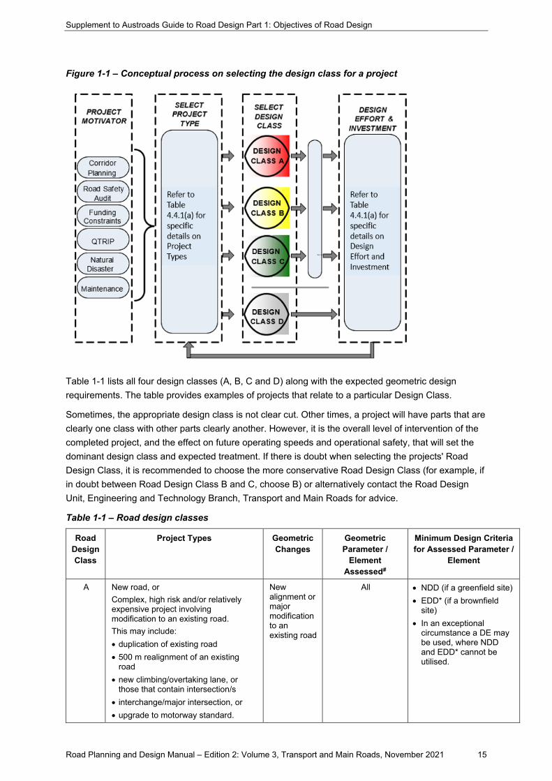
Figure 1-1 indicates a conceptual process for selecting design classes. The project could be in response to long term corridor planning or a recent natural disaster such as flooding. There are likely to be funding constraints identified prior to the commencement of the design process which must be considered.
Supplement to Austroads Guide to Road Design Part 1: Objectives of Road Design
Road Planning and Design Manual – Edition 2: Volume 3, Transport and Main Roads, November 2021 15
Figure 1-1 – Conceptual process on selecting the design class for a project
Table 1-1 lists all four design classes (A, B, C and D) along with the expected geometric design requirements. The table provides examples of projects that relate to a particular Design Class.
Sometimes, the appropriate design class is not clear cut. Other times, a project will have parts that are clearly one class with other parts clearly another. However, it is the overall level of intervention of the completed project, and the effect on future operating speeds and operational safety, that will set the dominant design class and expected treatment. If there is doubt when selecting the projects' Road Design Class, it is recommended to choose the more conservative Road Design Class (for example, if in doubt between Road Design Class B and C, choose B) or alternatively contact the Road Design Unit, Engineering and Technology Branch, Transport and Main Roads for advice.
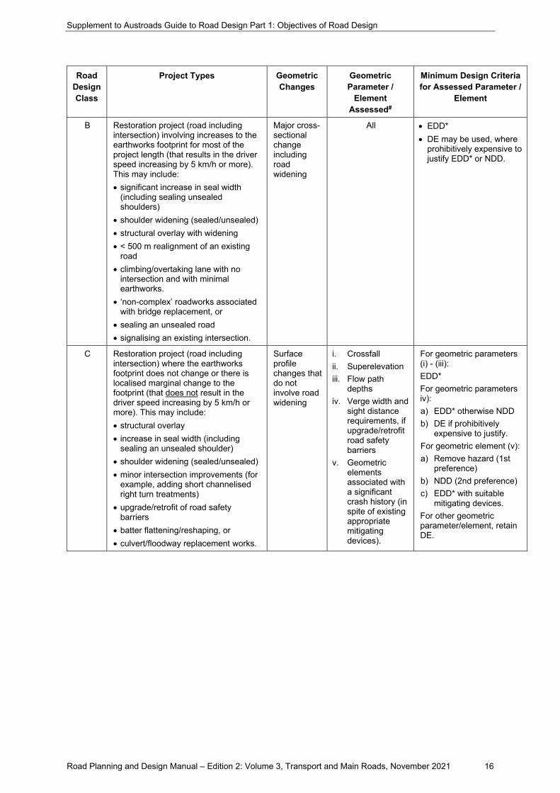
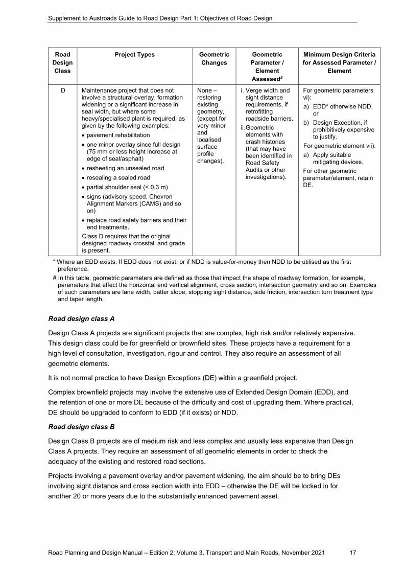
Table 1-1 – Road design classes
Road Design Class
Project Types Geometric Changes
Geometric Parameter /
Element Assessed#
Minimum Design Criteria for Assessed Parameter /
Element
A New road, or Complex, high risk and/or relatively expensive project involving modification to an existing road. This may include: • duplication of existing road • 500 m realignment of an existing
road • new climbing/overtaking lane, or
those that contain intersection/s • interchange/major intersection, or • upgrade to motorway standard.
New alignment or major modification to an existing road
All • NDD (if a greenfield site) • EDD* (if a brownfield
site) • In an exceptional
circumstance a DE may be used, where NDD and EDD* cannot be utilised.
Supplement to Austroads Guide to Road Design Part 1: Objectives of Road Design
Road Planning and Design Manual – Edition 2: Volume 3, Transport and Main Roads, November 2021 16
Road Design Class
Project Types Geometric Changes
Geometric Parameter /
Element Assessed#
Minimum Design Criteria for Assessed Parameter /
Element
B Restoration project (road including intersection) involving increases to the earthworks footprint for most of the project length (that results in the driver speed increasing by 5 km/h or more). This may include: • significant increase in seal width
(including sealing unsealed shoulders)
• shoulder widening (sealed/unsealed) • structural overlay with widening • < 500 m realignment of an existing
road • climbing/overtaking lane with no
intersection and with minimal earthworks.
• ‘non-complex’ roadworks associated with bridge replacement, or
• sealing an unsealed road • signalising an existing intersection.
Major cross-sectional change including road widening
All • EDD* • DE may be used, where
prohibitively expensive to justify EDD* or NDD.
C Restoration project (road including intersection) where the earthworks footprint does not change or there is localised marginal change to the footprint (that does not result in the driver speed increasing by 5 km/h or more). This may include: • structural overlay • increase in seal width (including
sealing an unsealed shoulder) • shoulder widening (sealed/unsealed) • minor intersection improvements (for
example, adding short channelised right turn treatments)
• upgrade/retrofit of road safety barriers
• batter flattening/reshaping, or • culvert/floodway replacement works.
Surface profile changes that do not involve road widening
i. Crossfall ii. Superelevation iii. Flow path
depths iv. Verge width and
sight distance requirements, if upgrade/retrofit road safety barriers
v. Geometric elements associated with a significant crash history (in spite of existing appropriate mitigating devices).
For geometric parameters (i) - (iii): EDD* For geometric parameters iv): a) EDD* otherwise NDD b) DE if prohibitively
expensive to justify. For geometric element (v): a) Remove hazard (1st
preference) b) NDD (2nd preference) c) EDD* with suitable
mitigating devices. For other geometric parameter/element, retain DE.
Supplement to Austroads Guide to Road Design Part 1: Objectives of Road Design
Road Planning and Design Manual – Edition 2: Volume 3, Transport and Main Roads, November 2021 17
Road Design Class
Project Types Geometric Changes
Geometric Parameter /
Element Assessed#
Minimum Design Criteria for Assessed Parameter /
Element
D Maintenance project that does not involve a structural overlay, formation widening or a significant increase in seal width, but where some heavy/specialised plant is required, as given by the following examples: • pavement rehabilitation • one minor overlay since full design
(75 mm or less height increase at edge of seal/asphalt)
• resheeting an unsealed road • resealing a sealed road • partial shoulder seal (< 0.3 m) • signs (advisory speed, Chevron
Alignment Markers (CAMS) and so on)
• replace road safety barriers and their end treatments.
Class D requires that the original designed roadway crossfall and grade is present.
None – restoring existing geometry, (except for very minor and localised surface profile changes).
i. Verge width and sight distance requirements, if retrofitting roadside barriers.
ii. Geometric elements with crash histories (that may have been identified in Road Safety Audits or other investigations).
For geometric parameters vi): a) EDD* otherwise NDD,
or b) Design Exception, if
prohibitively expensive to justify.
For geometric element vii): a) Apply suitable
mitigating devices. For other geometric parameter/element, retain DE.
* Where an EDD exists. If EDD does not exist, or if NDD is value-for-money then NDD to be utilised as the first preference.
# In this table, geometric parameters are defined as those that impact the shape of roadway formation, for example, parameters that effect the horizontal and vertical alignment, cross section, intersection geometry and so on. Examples of such parameters are lane width, batter slope, stopping sight distance, side friction, intersection turn treatment type and taper length.
Road design class A
Design Class A projects are significant projects that are complex, high risk and/or relatively expensive. This design class could be for greenfield or brownfield sites. These projects have a requirement for a high level of consultation, investigation, rigour and control. They also require an assessment of all geometric elements.
It is not normal practice to have Design Exceptions (DE) within a greenfield project.
Complex brownfield projects may involve the extensive use of Extended Design Domain (EDD), and the retention of one or more DE because of the difficulty and cost of upgrading them. Where practical, DE should be upgraded to conform to EDD (if it exists) or NDD.
Road design class B
Design Class B projects are of medium risk and less complex and usually less expensive than Design Class A projects. They require an assessment of all geometric elements in order to check the adequacy of the existing and restored road sections.
Projects involving a pavement overlay and/or pavement widening, the aim should be to bring DEs involving sight distance and cross section width into EDD – otherwise the DE will be locked in for another 20 or more years due to the substantially enhanced pavement asset.
Supplement to Austroads Guide to Road Design Part 1: Objectives of Road Design
Road Planning and Design Manual – Edition 2: Volume 3, Transport and Main Roads, November 2021 18
However, any decision to upgrade a road section will be influenced by factors such as:
• crash history
• constructability and traffic management constraints
• project constraints, and
• cost (for example, it may not be cost effective to increase the size of a vertical curve through a major rock cutting).
Examples of specific instances where Design Exceptions should be upgraded include:
• Horizontal curves with:
− a crash history and which already have the appropriate signage, safety barriers or run-out areas, or
− an unsatisfactory combination of other design parameter minima.
• Intersections with deficient sight distance – experience shows it will end up being rebuilt sooner rather than later.
• Crests – these should be brought into EDD when:
− minimal earthworks are required (for example, less than a 1 m cut is required)
− rehabilitation or reconstruction of the existing pavement is required, or
− there is an unsatisfactory combination of other design parameter minima.
Road design class C
As outlined in Table 1-1, DEs for geometric elements such as crossfalls, superelevation, and flow path depths at curve transitions within Road Design Class C projects are normally expected to be upgraded. Normally, all other geometric elements comprising a DE (if known) are not expected to be upgraded. However, the following is required on all Class C projects:
• Review and upgrade signage if necessary, to comply with the Manual of Uniform Traffic Control Devices (Queensland) (MUTCD).
• Comply with the departmental policy on road safety auditing of projects.
• Seek to improve the geometry of any feature that has a significant crash history in spite of appropriate mitigating treatments already in place, and
• Mitigate geometric elements with a known crash history by:
− clearing roadside hazards
− updating/installing safety barriers and so on
− providing additional signage, and/or
− applying a speed limit reduction, if justified in accordance with Part 4 of the MUTCD.
For full shoulder sealing projects, it is desirable to be able to demonstrate that any DE (or any other geometric parameter for that matter) is not made worse. With these projects, it is desirable to undertake an assessment of all geometric elements in order to determine if there is any adverse effect due to increased operating speeds as a result of changed driver or rider perception of the road (for example, problem horizontal curves).
Supplement to Austroads Guide to Road Design Part 1: Objectives of Road Design
Road Planning and Design Manual – Edition 2: Volume 3, Transport and Main Roads, November 2021 19
Examples where a road could be made less safe with Design Classes C or D include:
• a seal width increase that results in the 85th percentile speed of the road rising above the geometric elements of the existing road, and/or
• a seal width increase that is implemented by significantly steepening the batters within the existing formation.
Road design class D
Design Class D projects have the lowest risk, complexity and are usually the less expensive. Examples may include pavement rehabilitation, or pavement rehabilitation with a minor or profile correcting overlay (where no earthworks / formation widening is required), or minor drainage and/or the maintenance of road safety barriers (limited to only replacing end treatments and existing components: no change to the points of redirection nor lateral offset is accommodated in Design Class D).
4.5 Design exception process
4.5.1 Design exceptions
Addition
Design exceptions (DE) are most likely to occur due to challenging terrain; constrictions due to existing infrastructure, services, property boundaries, environmental conditions, cultural heritage and community expectations; and so on.
Before any design exception is adopted it is necessary to demonstrate that the adoption of a design exception/s provides for a reasonable level of safety. This shall be fully documented in a design exception report and provided to the department. Further requirements can be found within the RPDM Part 1 Appendix A. A Design Exception Report example template can be found in RPDM Part 1 Appendix C.
The specific requirements detailed in the DDPSM for capturing and registering Extended Design Domain (EDD) Reports and Design Exception (DE) Reports into the Department of Transport and Main Roads Geospatial Information Management System (GIMS) for record keeping purposes must be followed.
4.5.2 Innovative and emerging treatments
Addition
For new and emerging treatments in Queensland, refer to the RPDM, Volume 3, Part 7 New and Emerging Treatments.
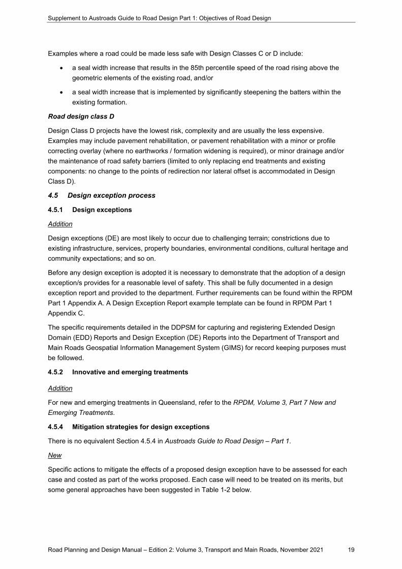
4.5.4 Mitigation strategies for design exceptions
There is no equivalent Section 4.5.4 in Austroads Guide to Road Design – Part 1.
New
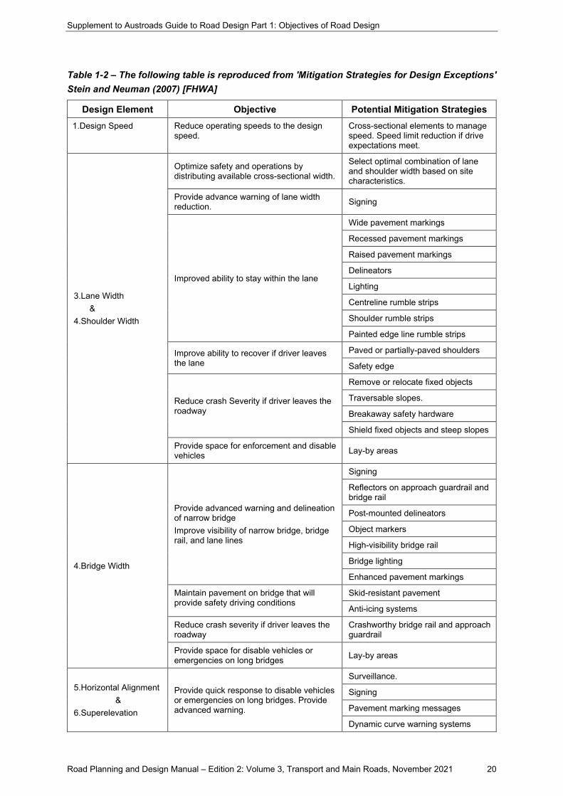
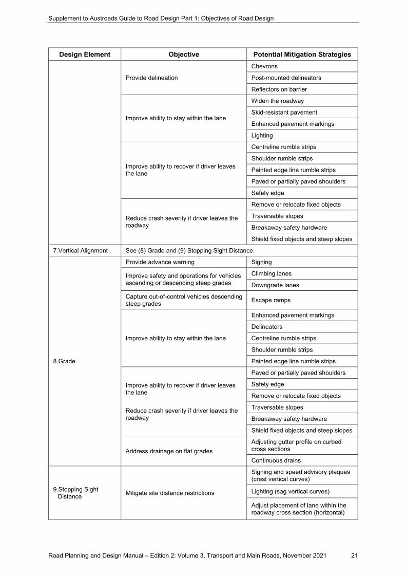
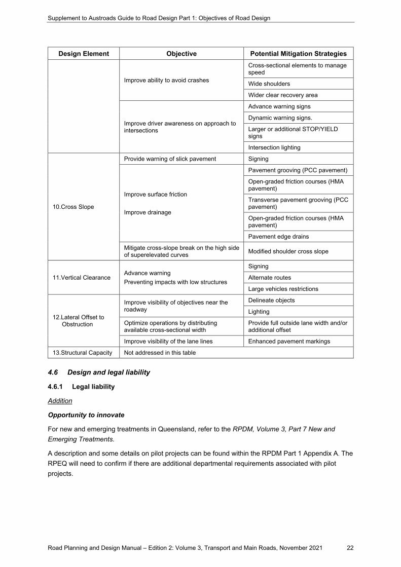
Specific actions to mitigate the effects of a proposed design exception have to be assessed for each case and costed as part of the works proposed. Each case will need to be treated on its merits, but some general approaches have been suggested in Table 1-2 below.
Supplement to Austroads Guide to Road Design Part 1: Objectives of Road Design
Road Planning and Design Manual – Edition 2: Volume 3, Transport and Main Roads, November 2021 20
Table 1-2 – The following table is reproduced from 'Mitigation Strategies for Design Exceptions' Stein and Neuman (2007) [FHWA]
Design Element Objective Potential Mitigation Strategies 1.Design Speed Reduce operating speeds to the design
speed. Cross-sectional elements to manage speed. Speed limit reduction if drive expectations meet.
3.Lane Width &
4.Shoulder Width
Optimize safety and operations by distributing available cross-sectional width.
Select optimal combination of lane and shoulder width based on site characteristics.
Provide advance warning of lane width reduction. Signing
Improved ability to stay within the lane
Wide pavement markings
Recessed pavement markings
Raised pavement markings
Delineators
Lighting
Centreline rumble strips
Shoulder rumble strips
Painted edge line rumble strips
Improve ability to recover if driver leaves the lane
Paved or partially-paved shoulders
Safety edge
Reduce crash Severity if driver leaves the roadway
Remove or relocate fixed objects
Traversable slopes.
Breakaway safety hardware
Shield fixed objects and steep slopes
Provide space for enforcement and disable vehicles Lay-by areas
4.Bridge Width
Provide advanced warning and delineation of narrow bridge Improve visibility of narrow bridge, bridge rail, and lane lines
Signing
Reflectors on approach guardrail and bridge rail
Post-mounted delineators
Object markers
High-visibility bridge rail
Bridge lighting
Enhanced pavement markings
Maintain pavement on bridge that will provide safety driving conditions
Skid-resistant pavement
Anti-icing systems
Reduce crash severity if driver leaves the roadway
Crashworthy bridge rail and approach guardrail
Provide space for disable vehicles or emergencies on long bridges Lay-by areas
5.Horizontal Alignment &
6.Superelevation
Provide quick response to disable vehicles or emergencies on long bridges. Provide advanced warning.
Surveillance.
Signing
Pavement marking messages
Dynamic curve warning systems
Supplement to Austroads Guide to Road Design Part 1: Objectives of Road Design
Road Planning and Design Manual – Edition 2: Volume 3, Transport and Main Roads, November 2021 21
Design Element Objective Potential Mitigation Strategies
Provide delineation
Chevrons
Post-mounted delineators
Reflectors on barrier
Improve ability to stay within the lane
Widen the roadway
Skid-resistant pavement
Enhanced pavement markings
Lighting
Improve ability to recover if driver leaves the lane
Centreline rumble strips
Shoulder rumble strips
Painted edge line rumble strips
Paved or partially paved shoulders
Safety edge
Reduce crash severity if driver leaves the roadway
Remove or relocate fixed objects
Traversable slopes
Breakaway safety hardware
Shield fixed objects and steep slopes
7.Vertical Alignment See (8) Grade and (9) Stopping Sight Distance.
8.Grade
Provide advance warning Signing
Improve safety and operations for vehicles ascending or descending steep grades
Climbing lanes
Downgrade lanes
Capture out-of-control vehicles descending steep grades Escape ramps
Improve ability to stay within the lane
Enhanced pavement markings
Delineators
Centreline rumble strips
Shoulder rumble strips
Painted edge line rumble strips
Improve ability to recover if driver leaves the lane Reduce crash severity if driver leaves the roadway
Paved or partially paved shoulders
Safety edge
Remove or relocate fixed objects
Traversable slopes
Breakaway safety hardware
Shield fixed objects and steep slopes
Address drainage on flat grades Adjusting gutter profile on curbed cross sections
Continuous drains
9.Stopping Sight Distance Mitigate site distance restrictions
Signing and speed advisory plaques (crest vertical curves)
Lighting (sag vertical curves)
Adjust placement of lane within the roadway cross section (horizontal)
Supplement to Austroads Guide to Road Design Part 1: Objectives of Road Design
Road Planning and Design Manual – Edition 2: Volume 3, Transport and Main Roads, November 2021 22
Design Element Objective Potential Mitigation Strategies
Improve ability to avoid crashes
Cross-sectional elements to manage speed
Wide shoulders
Wider clear recovery area
Improve driver awareness on approach to intersections
Advance warning signs
Dynamic warning signs.
Larger or additional STOP/YIELD signs
Intersection lighting
10.Cross Slope
Provide warning of slick pavement Signing
Improve surface friction Improve drainage
Pavement grooving (PCC pavement)
Open-graded friction courses (HMA pavement)
Transverse pavement grooving (PCC pavement)
Open-graded friction courses (HMA pavement)
Pavement edge drains
Mitigate cross-slope break on the high side of superelevated curves Modified shoulder cross slope
11.Vertical Clearance Advance warning Preventing impacts with low structures
Signing
Alternate routes
Large vehicles restrictions
12.Lateral Offset to Obstruction
Improve visibility of objectives near the roadway
Delineate objects
Lighting
Optimize operations by distributing available cross-sectional width
Provide full outside lane width and/or additional offset
Improve visibility of the lane lines Enhanced pavement markings
13.Structural Capacity Not addressed in this table 4.6 Design and legal liability
4.6.1 Legal liability
Addition
Opportunity to innovate
For new and emerging treatments in Queensland, refer to the RPDM, Volume 3, Part 7 New and Emerging Treatments.
A description and some details on pilot projects can be found within the RPDM Part 1 Appendix A. The RPEQ will need to confirm if there are additional departmental requirements associated with pilot projects.
Supplement to Austroads Guide to Road Design Part 1: Objectives of Road Design
Road Planning and Design Manual – Edition 2: Volume 3, Transport and Main Roads, November 2021 23
4.7 Coordination of disciplines
Difference
In 'Table 4.5 Checklist for design considerations' under the design consideration row titled 'Risk Management' modify the likely source column to only state 'All stakeholders' rather than 'Independent safety audit team via the project sponsor'.
5 The road design process
5.1 General
Addition
It is recommended that the Road Design Unit, Engineering and Technology Branch, Transport and Main Roads be engaged to provide a review of all Transport and Main Roads' projects, particularly early in the project lifecycle.
Our review is intended to be high-level, adding value to the design with respect to safety, appropriateness and affordability. Early engagement typically produces value for money results, avoids reputational risks and missed opportunities, ensures consistency and quality. This review does not replace the design verification or quality processes.
Review services that could be undertaken relate to the technical aspects associated with the typical stages of a project lifecycle, such as:
• Strategic needs assessment and planning
• Concept
• Feasibility
• Options development
• Business case
• Preliminary and detailed design
• Scoping, design briefs and contract documentation, and
• Development of Scope of Works and Technical Criteria (SWTC).
5.2 Design report
5.2.1 Design report content
Addition
Land use
Refer to the Department of State Development, Infrastructure, Local Government and Planning for the latest information on planning.
Transport
The TMR Transport Coordination and Delivery Plan 2017-2027 sets departmental strategy and direction to deliver on the government’s objectives of a 10 year horizon. It provides a clear strategic framework for making decisions to achieve the government’s vision for the transport system and is supported by:
• criteria for making decisions about spending on transport
Supplement to Austroads Guide to Road Design Part 1: Objectives of Road Design
Road Planning and Design Manual – Edition 2: Volume 3, Transport and Main Roads, November 2021 24
• long-term objectives and performance indicators for the transport system
• guiding principles that inform policy, planning and decision making
• a simple governance structure with clear accountabilities
• the annual strategic plan provides strategic business priorities and objectives.
Further documents that planning and design teams need to be aware of are (but not limited to):
• Queensland Transport and Roads Investment Program
• Transport Infrastructure Act 1994
• Transport Planning and Coordination Act 1994
• Transport Planning and Coordination Regulation 2005.
Environmental
The department’s Environmental Processes Manual provides the governance for environmental assessment and management of transport infrastructure projects undertaken by the department.
Cultural heritage
Cultural heritage (both Indigenous and European) issues must be identified and their impact must be considered in the planning and design process. For initial guidance on matters related to indigenous cultural heritage reference must be made to the Cultural Heritage Process Manual.
Supplement to Austroads Guide to Road Design Part 1: Objectives of Road Design
Road Planning and Design Manual – Edition 2: Volume 3, Transport and Main Roads, November 2021 25
References
Transport and Main Roads publication references refer to the latest published document on the departmental website (www.tmr.qld.gov.au).
Addition
Arndt, O. K. and Peters, J. K. and Cox, R. L. (2009). The Effect of Combining Geometric Minima Findings from Case Studies, A paper prepared for the 4th International Symposium on Highway Geometric Design
AASHTO (2010) Highway Safety Manual Edition 1, American Association of Highway and Transportation Officials, Washington DC
AASHTO (2011). A Policy on Geometric Design of Highways and Streets, Washington DC, USA
Austroads (2015). Guide to Road Design Part 1, Introduction to Road Design, Austroads, Sydney, NSW
Austroads (2010). Guide to Road Design Part 6, Roadside Design, Safety and Barriers, Austroads, Sydney, NSW
Austroads (2010a), Road Safety Engineering Risk Assessment Part 1: Relationship between Crash Risk and the Standards of Geometric Design Elements (Report AP-T146/10)
Austroads (2010b), Road Safety Engineering Risk Assessment Part 6: Crash Reduction Factors (Report AP-T151/10)
Austroads (2014) Australian National Risk Assessment Model, Sydney, NSW
Austroads (2014). Cycling Aspects of Austroads Guides, Austroads, Sydney, NSW
ARRB (2012). SP1705 Progress Report No.5: Safe System Design Principles for Brownfield Sites
Cox, R.L. (2004). Process for using Extended Design Domain on a Restoration Project, presentation at Department of Main Roads Extended Design Domain Training course
Department of State Development, Infrastructure and Planning (2014). State Planning Policy, Brisbane, QLD
Department of Transport and Main Roads (2014). Communication plan and material approval standard, Brisbane, QLD
Department of Transport and Main Roads (2011). Cost-benefit Analysis Manual, Brisbane, QLD
Department of Transport and Main Roads (2013). Cultural Heritage Process Manual, Brisbane, QLD
Department of Transport and Main Roads (2013). Cycling Infrastructure Policy, Brisbane, QLD
Department of Transport and Main Roads Design Development Report (large projects), Brisbane, QLD
Department of Transport and Main Roads Design Development Report (small projects), Brisbane, QLD
Department of Transport and Main Roads (2005). Easy Steps: A toolkit for planning, designing and promoting safe walking, Brisbane, QLD
Department of Transport and Main Roads Engineering Innovation within the Department of Transport and Main Roads, Brisbane, QLD
Supplement to Austroads Guide to Road Design Part 1: Objectives of Road Design
Road Planning and Design Manual – Edition 2: Volume 3, Transport and Main Roads, November 2021 26
Department of Transport and Main Roads (2013). Environmental Processes Manual, Brisbane, QLD
Department of Transport and Main Roads Functional specification templates C7521 Options analysis, Brisbane, QLD
Department of Transport and Main Roads Functional specification templates C7522 Business case, Brisbane, QLD
Department of Transport and Main Roads Functional specification templates C7523 Preliminary design, Brisbane, QLD
Department of Transport and Main Roads Functional specification templates C7524 Detailed design, Brisbane, QLD
Department of Transport and Main Roads Geotechnical Design Standard – Minimum Requirements, Brisbane, QLD
Department of Transport and Main Roads (2006). Guidelines for Assessment of Road Impacts of Development (GARID), Brisbane, QLD
Department of Transport and Main Roads. Manual of Uniform Traffic Control Devices, Brisbane, QLD
Department of Transport and Main Roads Technical Specification MRTS04 General Earthworks, Brisbane, QLD
Department of Transport and Main Roads (2009). Principal Cycle Network Plan – Far North Queensland, Brisbane, QLD
Department of Transport and Main Roads Project Scoping Guideline, Brisbane, QLD
Department of Transport and Main Roads (2011). Queensland Cycle Strategy 2011-2021, Brisbane, QLD
Department of Transport and Main Roads. Road Planning and Design Manual, Brisbane, QLD
Department of Transport and Main Roads (2008). Road Safety Audit Policy, Brisbane, QLD
Department of Transport and Main Roads. Road Safety Audit Policy Supporting Guidelines, Brisbane, QLD
Department of Transport and Main Roads. Safer Roads, Safer Queensland, Queensland’s Road Safety Strategy 2015-21, Brisbane, QLD
Department of Transport and Main Roads (2009). South East Queensland Principal Cycle Network Plan, Brisbane, QLD
Department of Transport and Main Roads (2011). State-controlled Priority Road Network Investment Guidelines, Brisbane, QLD
Department of Transport and Main Roads. Strategic Plan 2016-2020, Brisbane, QLD
Department of Transport and Main Roads. Traffic and Road Use Management Manual (TRUM), Brisbane, QLD
Department of Transport and Main Roads (2013). Transport Coordination and Delivery Plan, Brisbane, QLD
Fambro, D., Fitzpatrick, K., Koppa, R. (1997). Determination of stopping sight distances - Report 400, National Cooperative Highway Research Program, Transportation Research Board
Supplement to Austroads Guide to Road Design Part 1: Objectives of Road Design
Road Planning and Design Manual – Edition 2: Volume 3, Transport and Main Roads, November 2021 27
Fuller, R. and Santos, J. (2002). Human factors for highway engineers, Pergamon - Elesevier Science Ltd, Oxford, UK
Hauer, E. (1998). Literature review and analysis on collision rates on vertical alignment, University of Toronto (reported in Geometric design Guide for Canadian Roads, 1999)
Hauer, E. (1999). Safety in Geometric Design Standards, University of Toronto (reported in Geometric design Guide for Canadian Roads, 1999)
Lay, M. G. (1998). Handbook of Road Technology – Volume 2 Traffic and Transport, Gordon and Breach Science Publishers
Louis, L. (2002). Design standards and approach to 'Fit for Purpose''
National Cooperative Highway Research Program (NCHRP) (2003). Report 500: Guidance for Implementation of the AASHTO Strategic Highway Safety Plan (13 volumes)
NCHRP (2012). Recent Roadway Geometric Design Research for Improved Safety and Operations – A Synthesis of Highway Practice. NCHRP Synthesis 432
Olsen, P., Cleveland, D., Fancher, P., Kostyniuk, L., Schneider, L., Arbor, A. (1984). Parameters affecting stopping sight distance - Report 270, Transportation Research Board
Oxley, J., Corben, B., Koppel, S., Fildes, B., Jacques, N., Symmons, M., and Johnston, I. (2004). Cost-Effective Infrastructure Measures on Rural Roads - Monash University Accident Research Centre – Report No. 217
Queensland Government (2015). Transport Infrastructure Act 1994, QLD
Queensland Government (2018). Human-Centred Design (HCD) in Queensland Government toolkit
Stein, W. J. and Neuman, T. R. (2007). Mitigation Strategies for Design Exceptions, Federal Highway Administration Report FHWA-SA-07-011
Transportation Association of Canada (1999). Geometric Design Guide for Canadian Roads, Ottawa, Canada
Workplace Health and Safety Queensland (2011). Work Health and Safety Act, (https://www.worksafe.qld.gov.au), Brisbane, QLD
Workplace Health and Safety Queensland (2011). Work Health and Safety Regulation, (https://www.worksafe.qld.gov.au), Brisbane, QLD
Workplace Health and Safety Queensland (2013). Legislative guide–designer written report for a structure (LG-DR), (https://www.worksafe.qld.gov.au), Brisbane, QLD
Workplace Health and Safety Queensland (2013). Safe design of structures code of practice 2013, (https://www.worksafe.qld.gov.au), Brisbane, QLD
Legal Case: Theden v Nominal Defendant [2004] QSC 310
Supplement to Austroads Guide to Road Design Part 1: Objectives of Road Design
Road Planning and Design Manual – Edition 2: Volume 3, Transport and Main Roads, November 2021 28
Appendix A – Process and documentation
Addition
Compliance with the Professional Engineers Act 2002
All transport infrastructure designs produced for the Department of Transport and Main Roads in Queensland must be certified by a Registered Professional Engineer of Queensland (RPEQ). If there is any reduction in the standard, the certifying RPEQ needs to ensure that sufficient engineering rigor is undertaken. The reduction in standard must be justifiable/defendable to ensure it doesn’t adversely affect suitable and recognised levels of safety and operation of the road.
It is the role of the RPEQ to ensure that the use of the design standards are appropriate given the context of the project, and that the departments’ processes have been followed.
No RPEQ should accept the engineering responsibility for any design or design component that cannot be justified and defended.
If the design cannot meet the expectations of the brief within budget because particular design exceptions are unable to be justified, then the designer would be expected to work with the project manager to reduce costs by scope reduction (e.g. shortening the job or removing components that don’t adversely affect the desired outcomes from the project brief).
A.1 Preparation for design
A.1.5 Scope of the design
Addition
The design brief
The design brief should be based on the templates that have been developed for the four major stages of preconstruction. The Transport and Main Roads templates are available on the departmental website and include:
i. C7521 Options Analysis
ii. C7522 Business Case
iii. C7523 Preliminary Design
iv. C7524 Detailed Design.
The development of the design brief utilising the content of the relevant functional specification templates provides a structured framework to ensure:
• the scope is adequately defined
• the management of the design is undertaken in such a way that the original scope is adequately and regularly monitored against the identified needs and functionality (utilising the Design Development Report), and
• any identified changes to scope are appropriately investigated and approval sought before being undertaken.
Measures of success (Success Criteria) need to be detailed in the design brief to facilitate the design review process at completion of the design. These may include reduction in design cost or timeframes, reduced project risk, innovative solutions, project learnings or improved processes that may be transferrable to future projects.
Supplement to Austroads Guide to Road Design Part 1: Objectives of Road Design
Road Planning and Design Manual – Edition 2: Volume 3, Transport and Main Roads, November 2021 29
The significant elements that are to be included in the design brief should include but are not limited to:
• liaison with the Principal
• project management
• environmental management
• public consultation
• hydraulic analysis and design
• public utility plant
• lighting, traffic signals, and intelligent transport systems
• landscaping and/or revegetation
• geotechnical investigations
• road/bridge design and drawings
• design development reports and project plans
• safety in design
• detailed estimate of cost
• contract documentation
• road safety audits and risk mitigation
• constructability requirements
• integration with adjacent infrastructure
• maintenance requirements
• operations requirements, and
• durability / whole of life performance and intervention requirements.
The road infrastructure project scope is defined within the context of the required outcomes, and in accordance with the operational objectives outlined in the component elements contained in the design brief. It is important that the elements in the design brief clearly define what is 'in scope' and 'out of scope' for the project.
Decisions made during the design process are to be recorded in the design development report. Sample contents for the design development reports are available from Transport and Main Roads Design Development Report (Large Projects) and Design Development Report (Small Projects).
Innovation in design is encouraged and should figure prominently in the design brief. The department expects design consultants to actively optimise design and seek guidance on innovative options and the risk appetite of the client. Consultants are expected to consider and deliver, where appropriate, suitable extensions of the design domain that provide savings and an appropriate level of safety.
Processes for the inclusion of innovations within the design brief are included in Transport and Main Roads Project Scoping Guideline and Engineering Innovation within the Department of Transport and Main Roads.
Supplement to Austroads Guide to Road Design Part 1: Objectives of Road Design
Road Planning and Design Manual – Edition 2: Volume 3, Transport and Main Roads, November 2021 30
A.1.6 Design development inputs
Addition
Guidance on areas of potential impact
Refer to the Department of Transport and Main Roads Guide to Traffic Impact Assessment and departmental traffic data as the primary reference for information related to traffic forecasting, estimates and so on.
Road safety audits
Road safety audits must be conducted in line with the department’s:
• Road Safety Audit Policy
• Road Safety Audit Policy – Supporting Guidelines, and
• Traffic and Road Use Manual – Volume 2: Guide to Road Safety.
Road safety audit is a process intended to assist road authorities in improving road safety on their road network through the application of road safety engineering knowledge and experience.
Road safety audits on state-controlled roads can only be completed by a registered road safety auditor.
A.1.7 Design development output
Addition
Safety in Design Report
The content of a Safety in Design Report, where required:
• Must document risks to the health and safety of construction and maintenance personnel both during the initial construction of the project and while undertaking construction/maintenance/ demolition activities at any future stage.
• May document risks to individuals travelling through the construction site, including vehicular and pedestrian traffic, if the risks are considered to be of significance and not specifically covered in standard reference material outlined below. Suitable risk mitigation strategies for this scenario can be achieved by applying the appropriate design criteria in this Road Planning and Design Manual and the Transport and Main Roads Manual of Uniform Traffic Control Devices.
• Would not normally include risks to drivers travelling through the project after construction has been completed. These risks should be mitigated by applying the appropriate design criteria in this Road Planning and Design Manual and other industry standards relating to road design and road safety audits.
The Safety in Design Report will be passed from phase to phase along with other design development documentation to demonstrate a continuous flow of risk identification and elimination / mitigation.
The Safety in Design Report is required to be completed at the following stages of the design process:
• Concept phase - business case. Deliverables: Design Development Report, Road Safety Audit, and a Safety in Design Report.
Supplement to Austroads Guide to Road Design Part 1: Objectives of Road Design
Road Planning and Design Manual – Edition 2: Volume 3, Transport and Main Roads, November 2021 31
• Development phase – preliminary design. Deliverables: Updated Design Development Report, Road Safety Audit, Reference Design, Risk Management Record, and a Safety in Design Report. Where the Preliminary Design precedes the Business Case, Safety in Design Reports are still required at completion of both stages.
• Development phase – detailed design. Deliverables: Updated Design Development Report, Road Safety Audit, Risk Management Record, and a Safety in Design Report.
The department will follow a similar path to that outlined in the WorkCover Safe Design of Structures Code of Practice. The WorkCover Legislative Guide – Designer Written Report for a Structure (LG-DR) provides additional guidance on the design procedures for safety in design.
Step 1: Identify stakeholders who will need to be consulted with during the design development starting at the concept stage and undertake some initial planning and design activities based on information obtained during the options analysis stage.
Step 2: Document perceived risks to personnel during the construction, maintenance or demolition phases of the project.
Step 3: Undertake consultation with relevant stakeholders to determine whether the risk can be eliminated from the design or minimised as far as is reasonably practicable. Reference to recognised standards should be made in order to determine how the hazard may be prevented or eliminated. People with specific skills and expertise from the construction, maintenance, and health and safety areas will need to be included in the design team or consulted during the design process to fill any knowledge gaps.
Step 4: Document all remaining risks that will need controls to be implemented in the relevant phase of the project lifecycle. Where temporary works and traffic control arrangements are proposed during construction, risk assessment of these measures also needs to be done. Documented risks and risk assessments should accompany the design at all times.
Step 5: For designs with unusual or atypical features, review the design and compile a Safety in Design Report that demonstrates how each of the steps above have been undertaken. Compilation of the resultant risk assessment matrix to be passed to the next phase of the design development, construction, or maintenance activities should be included as part of the report.
The Report should highlight any unusual or atypical features that pose a risk to health and safety of workers during the construction phase.
A.2 Design development
A.2.1 Overview
Addition
The State of Queensland is responsible for regulating and enforcing its work health and safety laws. All transport infrastructure projects must comply with Queensland’s Work Health and Safety legislation, which includes the Workplace Health and Safety Work Health and Safety Act 2011 and Work Health and Safety Regulation 2011.
Further guidance on the inclusion of these requirements within the design of transport infrastructure can be found in the Workplace Health and Safety Safe Design of Structures Code of Practice.
Supplement to Austroads Guide to Road Design Part 1: Objectives of Road Design
Road Planning and Design Manual – Edition 2: Volume 3, Transport and Main Roads, November 2021 32
A.2.2 Producing the road design
Addition
Departmental approval for EDD
The implementation of the Extended Design Domain (EDD) concept was approved for use in the department by the then Deputy Director General in May 2004. This direction was further supported by a similar memorandum in 2007. The following requirements are still as relevant now as they were when first implemented and reflect the current departmental position to be followed regarding the use of EDD:
1. The type of project is appropriate for the use of EDD standards. Refer to Road Design Classes for further guidance regarding the department’s expectations with respect to relevant design criteria’s design domain.
2. For Transport and Main Roads acceptance of the use of EDD standards, the Transport and Main Roads Project Representative is to approve the use of EDD standards and proposed mitigating treatments. The Project Representative should be determined by the risk profile of the project. It is the Project Sponsor's (typically the Regional / District Director) responsibility to accept or nominate an appropriate Project Representative to fulfill this role.
3. For those projects where the application of EDD standards is considered more difficult or non-standard, refer to Engineering and Technology (E&T) Branch for guidance.
4. Inclusion and justification of the use of EDD standards in Options Analysis and Business Case development.
5. Specifying the use of EDD standards in project documentation including briefs to consultants.
6. Documentation of the rationale of the use of the EDD, and
7. Using design values below the EDD requires a rigorous risk management approach, mitigating treatments and an even higher level of supporting documentation than for EDD.
Departmental approval for design exception
The current departmental position to be followed regarding the use of Design Exception (DE):
1. The type of project is appropriate for the use of DE standards. Refer to Road Design Classes for further guidance regarding the department’s expectations with respect to relevant design criteria’s design domain.
2. For Transport and Main Road's acceptance of the use of DE standards, the Transport and Main Roads Project Representative is to approve the use of DE standards and proposed mitigating treatments. The Project Representative should be determined by the risk profile of the project. It is the Project Sponsor's (typically the Regional / District Director) responsibility to accept or nominate an appropriate Project Representative to fulfill this role.
3. For those projects where the application of DE standards is considered more difficult or non-standard, refer to Engineering and Technology (E&T) Branch for guidance.
4. Inclusion and justification of the use of DE standards in Options Analysis and Business Case development.
5. Specifying the use of DE standards in project documentation including briefs to consultants.
6. Documentation of the rationale of the use of the DE, and
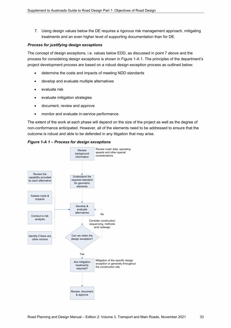
Supplement to Austroads Guide to Road Design Part 1: Objectives of Road Design
Road Planning and Design Manual – Edition 2: Volume 3, Transport and Main Roads, November 2021 33
7. Using design values below the DE requires a rigorous risk management approach, mitigating treatments and an even higher level of supporting documentation than for DE.
Process for justifying design exceptions
The concept of design exceptions, i.e. values below EDD, as discussed in point 7 above and the process for considering design exceptions is shown in Figure 1-A 1. The principles of the department’s project development process are based on a robust design exception process as outlined below:
• determine the costs and impacts of meeting NDD standards
• develop and evaluate multiple alternatives
• evaluate risk
• evaluate mitigation strategies
• document, review and approve
• monitor and evaluate in-service performance.
The extent of the work at each phase will depend on the size of the project as well as the degree of non-conformance anticipated. However, all of the elements need to be addressed to ensure that the outcome is robust and able to be defended in any litigation that may arise.
Figure 1-A 1 – Process for design exceptions
Review background information
Understand the required standard
for geometric elements
Can we retain the design exception?
Are mitigation treatments required?
Review, document & approve
Review crash data, operating speeds and other special considerations
Yes
No
Consider construction sequencing, methods
and/ redesign
Mitigation of the specific design exception or generally throughout the construction site.
Review the capability provided by each alternative
Assess costs & impacts
Conduct a risk analysis
Identify if there are other minima
Develop & evaluate
alternatives
Supplement to Austroads Guide to Road Design Part 1: Objectives of Road Design
Road Planning and Design Manual – Edition 2: Volume 3, Transport and Main Roads, November 2021 34
Types of design exception
There are three broad forms of design exception to be considered:
1. A pre-existing design exception – these design exceptions are typically those where an upgrade project is occurring and an existing design exception, inherent in the existing road layout, is proposed to be retained. Examples include:
• an existing vertical crest curve not meeting sight distance requirements on a section of road to be resurfaced and widened on the existing formation
• an existing short length merge on the exit from a signalised intersection which is being upgraded on the cross road
• existing narrow lanes in a constrained urban area which are being retained with reallocation of the roadside space to introduce bus lanes.
2. The introduction of a new design exception to the road network based on other similar designs existing on the road network. While not meeting design standards the similar designs perform to an acceptable safety level. The key element to these types of design exceptions are that precedents exist elsewhere in the network to support the expected performance. Examples of these may include:
• introduction of a short merge on the exit to a roundabout which has been converted from one lane to two lane
• widening of a roundabout approach from one to two lanes but with lane widths and/or alignment not meeting EDD
• introducing a vertical crest not meeting sight distance criteria in a constrained location but with mitigating treatments similar to other nearby locations on the same road.
3. The introduction of a new design exception to the road network for which there is no precedent, and which do not conform to current road design practice. These are referred to as Pilot projects. These design elements may arise when introduction of an innovative new design concept is proposed, or when constraints force designers to develop a design which has not previously been applied elsewhere on the network. These projects are to be assessed as trials for new designs that have no precedent in existing design practice with an unknown potential performance. Due to the lack of comparable data, Pilot projects present levels of risk to road users that may not be readily estimated or known. They therefore require a more rigorous level of assessment and post implementation monitoring to ensure that risks to road users are managed appropriately.
Developing alternatives
To defend a decision to adopt a design exception, the RPEQ will be required to demonstrate that in the process of adopting it, an evaluation of the impacts of providing the chosen design parameter value/s has been undertaken. Alternatives including one that meets the Normal Design Domain (NDD) or Extended Design Domain (EDD) standards will need to be developed and evaluated to a level that is reasonable and practical for the particular design.
Supplement to Austroads Guide to Road Design Part 1: Objectives of Road Design
Road Planning and Design Manual – Edition 2: Volume 3, Transport and Main Roads, November 2021 35
Evaluation and assessment will require:
• Presentation of information to demonstrate the impacts of meeting the minimum or lower design criteria. This can include but is not limited to:
o construction costs
o environmental consequences
o right-of-way impacts, and
o community involvement/concerns.
• Sufficient information to demonstrate the consequences of using a design value that does not meet the minimum criteria must be provided. Where appropriate, this may include but is not limited to:
o impacts on traffic serviceability (i.e. level of service)
o impacts on safety (i.e. crash history)
o impacts on traffic operations, and
o impacts on future maintenance.
• A written summary of the information is required and has to be submitted for review.
This will require sufficient design to allow reasonable estimates of cost to be developed and the impacts to be assessed. It is not sufficient to assume that retention of the existing is the only solution that needs to be evaluated.
Evaluation and risk assessment
Risk assessment is an essential part of all design but especially so for a design incorporating design exceptions. Evaluating the risk comprises an important part of the sequence of activities required.
The following questions need to be addressed both singly and in combination in order to assess the risk involved.
• What are the traffic volumes, the composition of traffic, and speeds?
• What is the degree/severity of the design exception?
• Are there multiple design exceptions at the same location?
• What is the length of the design exception?
• What is the expected duration of the design exception?
• Where is the location of the design exception relative to other risk factors?
• What is the substantive safety at the design exception location?
Further exploration of the impact of these considerations is outlined below.
Traffic
Important inputs include the total volume and the type of traffic. The type refers both to the types of vehicles (specifically the heavy vehicles) and the type of user (e.g. tourist drivers; commuter traffic; local agricultural users).
The expectations of drivers unfamiliar with the road will be different from those of commuter traffic or local users. Unfamiliar drivers require greater reaction and decision times than regular commuters.
Supplement to Austroads Guide to Road Design Part 1: Objectives of Road Design
Road Planning and Design Manual – Edition 2: Volume 3, Transport and Main Roads, November 2021 36
The type of heavy vehicles is also important. The longer vehicles will require greater distances to manoeuvre and are less capable of deviating from their course when confronted by a situation requiring such action.
The speed of traffic in the section should be assessed from measurements at the site and the 85th percentile speed determined. This will provide an accurate assessment of the required design speed, assuming that the proposed works do not result in an increase in that speed.
Combined geometric features
It is always a requirement of the design process that the combination of design elements at a site be considered.
While an exception in one element may be able to be considered, more than one at the same site becomes increasingly difficult to justify and needs very careful consideration.
For example, the combination of sub-standard horizontal and vertical geometry together is unlikely. In all cases, other elements at the site should be designed to better than minimum standards to compensate for the sub-standard element.
In all cases, the design adopted must be justified in an EDD and design exception report.
Length of the design exception
Consideration needs to be given to whether this issue being considered is an isolated element or one of a series of such elements.
An isolated element (e.g. crest curve) may be provided with mitigation more easily than a series of sub-standard elements over some distance. If the series of elements occurs within a section where the speed is modified by the horizontal geometry, then the operating speed may be reduced, and the retention of the geometry made more acceptable. Reduction of the posted speed in these circumstances may provide an acceptable mitigating option.
Duration of the design exception
Further consideration must also be given to the length of time that the current geometry be retained.
Is it intended that the design exception will be retained for a longer period or is it intended to reconstruct the section in the reasonably near future (say within five years)? A long term requirement provides a significantly different perspective to the problem.
Location with respect to other risk factors
The combination of other geometric features was discussed above.
The location of roadside furniture and/or trees also has to be considered. If the exception is to be retained, then action to address these features will be required.
Substantive safety at the site
The substantive safety will be determined by the crash history of the site (and similar sites elsewhere) and the types of crashes that have occurred. These details must be obtained and careful analysis of them carried out.
It is necessary that the proposed works do not make the substantive safety any worse; preferably, the works should improve the situation.
The likely effects of the proposals may be assessed using such tools as the Austroads (2014) Australian National Risk Assessment Model (ANRAM), the ARRB Road Safety Risk Manager
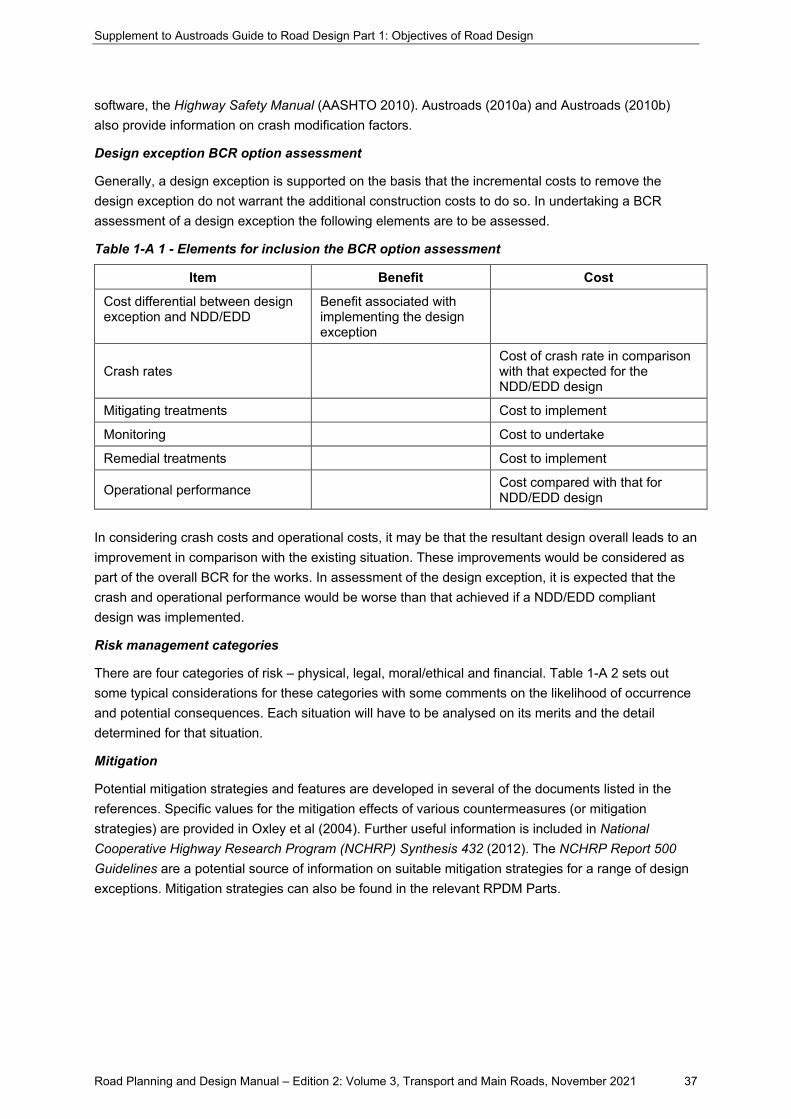
Supplement to Austroads Guide to Road Design Part 1: Objectives of Road Design
Road Planning and Design Manual – Edition 2: Volume 3, Transport and Main Roads, November 2021 37
software, the Highway Safety Manual (AASHTO 2010). Austroads (2010a) and Austroads (2010b) also provide information on crash modification factors.
Design exception BCR option assessment
Generally, a design exception is supported on the basis that the incremental costs to remove the design exception do not warrant the additional construction costs to do so. In undertaking a BCR assessment of a design exception the following elements are to be assessed.
Table 1-A 1 - Elements for inclusion the BCR option assessment
Item Benefit Cost
Cost differential between design exception and NDD/EDD
Benefit associated with implementing the design exception
Crash rates Cost of crash rate in comparison with that expected for the NDD/EDD design
Mitigating treatments Cost to implement
Monitoring Cost to undertake
Remedial treatments Cost to implement
Operational performance Cost compared with that for NDD/EDD design
In considering crash costs and operational costs, it may be that the resultant design overall leads to an improvement in comparison with the existing situation. These improvements would be considered as part of the overall BCR for the works. In assessment of the design exception, it is expected that the crash and operational performance would be worse than that achieved if a NDD/EDD compliant design was implemented.
Risk management categories
There are four categories of risk – physical, legal, moral/ethical and financial. Table 1-A 2 sets out some typical considerations for these categories with some comments on the likelihood of occurrence and potential consequences. Each situation will have to be analysed on its merits and the detail determined for that situation.
Mitigation
Potential mitigation strategies and features are developed in several of the documents listed in the references. Specific values for the mitigation effects of various countermeasures (or mitigation strategies) are provided in Oxley et al (2004). Further useful information is included in National Cooperative Highway Research Program (NCHRP) Synthesis 432 (2012). The NCHRP Report 500 Guidelines are a potential source of information on suitable mitigation strategies for a range of design exceptions. Mitigation strategies can also be found in the relevant RPDM Parts.
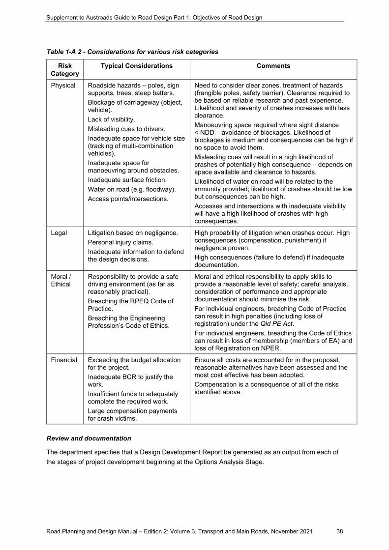
Supplement to Austroads Guide to Road Design Part 1: Objectives of Road Design
Road Planning and Design Manual – Edition 2: Volume 3, Transport and Main Roads, November 2021 38
Table 1-A 2 - Considerations for various risk categories
Risk Category
Typical Considerations Comments
Physical Roadside hazards – poles, sign supports, trees, steep batters. Blockage of carriageway (object, vehicle). Lack of visibility. Misleading cues to drivers. Inadequate space for vehicle size (tracking of multi-combination vehicles). Inadequate space for manoeuvring around obstacles. Inadequate surface friction. Water on road (e.g. floodway). Access points/intersections.
Need to consider clear zones, treatment of hazards (frangible poles, safety barrier). Clearance required to be based on reliable research and past experience. Likelihood and severity of crashes increases with less clearance. Manoeuvring space required where sight distance < NDD – avoidance of blockages. Likelihood of blockages is medium and consequences can be high if no space to avoid them. Misleading cues will result in a high likelihood of crashes of potentially high consequence – depends on space available and clearance to hazards. Likelihood of water on road will be related to the immunity provided; likelihood of crashes should be low but consequences can be high. Accesses and intersections with inadequate visibility will have a high likelihood of crashes with high consequences.
Legal Litigation based on negligence. Personal injury claims. Inadequate information to defend the design decisions.
High probability of litigation when crashes occur. High consequences (compensation, punishment) if negligence proven. High consequences (failure to defend) if inadequate documentation.
Moral / Ethical
Responsibility to provide a safe driving environment (as far as reasonably practical). Breaching the RPEQ Code of Practice. Breaching the Engineering Profession’s Code of Ethics.
Moral and ethical responsibility to apply skills to provide a reasonable level of safety; careful analysis, consideration of performance and appropriate documentation should minimise the risk. For individual engineers, breaching Code of Practice can result in high penalties (including loss of registration) under the Qld PE Act. For individual engineers, breaching the Code of Ethics can result in loss of membership (members of EA) and loss of Registration on NPER.
Financial Exceeding the budget allocation for the project. Inadequate BCR to justify the work. Insufficient funds to adequately complete the required work. Large compensation payments for crash victims.
Ensure all costs are accounted for in the proposal, reasonable alternatives have been assessed and the most cost effective has been adopted. Compensation is a consequence of all of the risks identified above.
Review and documentation
The department specifies that a Design Development Report be generated as an output from each of the stages of project development beginning at the Options Analysis Stage.
Supplement to Austroads Guide to Road Design Part 1: Objectives of Road Design
Road Planning and Design Manual – Edition 2: Volume 3, Transport and Main Roads, November 2021 39
The department requires the documentation of the following factors in the design documentation:
• project requirements
• existing conditions
• developing scope and identifying design inputs
• design parameters and issues
• design details
• record of design issues arising from process activities
• road safety audits, and
• actions.
The adoption of EDD is considered in the section of the Design Development Report relating to design parameters and issues. This section also provides for the documentation of potential impacts from the projects and anticipated project risks.
It is important that the documentation is clear and complete in terms understandable to others who may not be familiar with the project. It must also be clear to those who may need to defend the decisions a long time after the project is implemented.
The amount of documentation required, the content will vary according to the complexity of the EDD or design exception elements, and the level of intrusion into the extended design domain.
An example of a case where simple documentation may be appropriate could be a simple vertical crest on a horizontal straight where supplementary manoeuvre widening is available to provide capability to avoid small objects. In this example there is no crash history; no change in operating speed, no other geometric minima and it is only a minor intrusion into EDD.
In other cases, a significant intrusion into EDD might be considered in an extremely constrained area, but the level of documentation should be more detailed. For example, a Safe Intersection Sight Distance (SISD) value that is towards the bottom end of the EDD in conjunction with other design minima such as a tight horizontal curve.
For all design classes an EDD and Design Exceptions Report is required if certain geometric parameters and/or elements require assessment and an EDD/design exception is being proposed. Refer to Table 1-1 of Part 1 of this RPDM which details the minimum assessment for each design class.
Part 1 of this RPDM expands on this with the level of design effort expected. Note that following a speed assessment the original nominated design class should be re-categorised, so the works do not make the road 'less safe'.
Whatever EDD and design exception documentation is prepared should form part of the design development report.
Monitoring and evaluation
Where a design exception forms an element within a road project design, the project must include planning for the monitoring of the design exception and potential implementation of remedial treatments.
In all cases, the design exception needs to be systematically monitored to validate the decisions made and to provide information to make improvements to the process.
Supplement to Austroads Guide to Road Design Part 1: Objectives of Road Design
Road Planning and Design Manual – Edition 2: Volume 3, Transport and Main Roads, November 2021 40
Where it is found that the decision has not been successful in terms of maintaining or improving the substantive safety, the monitoring system will provide the information to allow appropriate modifications to be made to the road in question. A suitable system should collect data, analyse results and incorporate lessons learned in relevant guidelines and manuals.
The regime for the monitoring of the project performance post-implementation must be identified during the planning/design phase to allow an assessment of the project performance against that expected during the crash and risk analysis of the project. Where, the risk analysis identifies residual risks with a potential high severity outcome, or risks that cannot be accurately quantified, a higher level of monitoring will be required.
In considering the monitoring requirements to be addressed in the design report, the following need to be addressed:
• What is the recommended monitoring that should be used to determine whether the original problems have been dealt with in an 'on-going' manner?
• What are the issues that should be reviewed immediately after completion of the site works, after five years in service and at the end of fifteen years’ service?
An essential input into the monitoring process will be the crash statistics for the site in question. It may be necessary to examine the performance of adjacent sections to determine whether the works had a “migration” effect where crashes did not reduce but migrated to an adjacent section of road.
Each instance will need to be examined to see what the appropriate monitoring programme should be.
At the least, the following measures will be needed:
1. Roadway characteristics – cross section, geometry.
2. Signs and marking.
3. Presence of other road furniture (signals, lighting).
4. Crash history for as long a period as possible – not less than three years. This data should include the type, location, time, severity of crashes.
5. Traffic characteristics (volume, proportion and type of heavy vehicles, pedestrians (if applicable), cyclists (if applicable), speed).
For design exceptions where experience and crash histories indicate satisfactory performance, the normal black spot and safer roads sooner programs may suffice as the monitoring regime. For design exceptions, that are more unique and/or where their values are well outside of the design domain, a greater level of monitoring should be applied.
Planning should also be undertaken to implement appropriate alternative treatments where unacceptable safety risks become evident. This planning of remedial treatments should be undertaken as part of the design process for the design exception as shown in Figure 1-A 2.
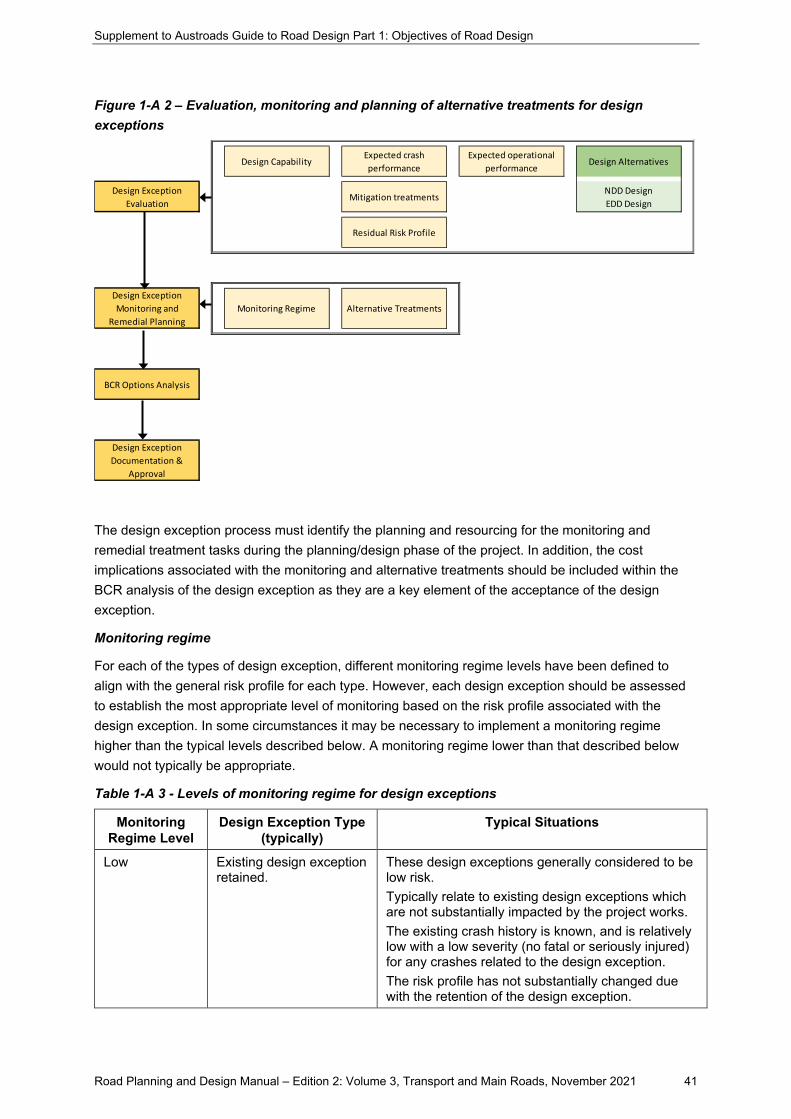
Supplement to Austroads Guide to Road Design Part 1: Objectives of Road Design
Road Planning and Design Manual – Edition 2: Volume 3, Transport and Main Roads, November 2021 41
Figure 1-A 2 – Evaluation, monitoring and planning of alternative treatments for design exceptions
The design exception process must identify the planning and resourcing for the monitoring and remedial treatment tasks during the planning/design phase of the project. In addition, the cost implications associated with the monitoring and alternative treatments should be included within the BCR analysis of the design exception as they are a key element of the acceptance of the design exception.
Monitoring regime
For each of the types of design exception, different monitoring regime levels have been defined to align with the general risk profile for each type. However, each design exception should be assessed to establish the most appropriate level of monitoring based on the risk profile associated with the design exception. In some circumstances it may be necessary to implement a monitoring regime higher than the typical levels described below. A monitoring regime lower than that described below would not typically be appropriate.
Table 1-A 3 - Levels of monitoring regime for design exceptions
Monitoring Regime Level
Design Exception Type (typically)
Typical Situations
Low Existing design exception retained.
These design exceptions generally considered to be low risk. Typically relate to existing design exceptions which are not substantially impacted by the project works. The existing crash history is known, and is relatively low with a low severity (no fatal or seriously injured) for any crashes related to the design exception. The risk profile has not substantially changed due with the retention of the design exception.
Design CapabilityExpected crash performance
Expected operational performance
Design Alternatives
Design Exception Evaluation
Mitigation treatmentsNDD DesignEDD Design
Residual Risk Profile
Design Exception Monitoring and
Remedial PlanningMonitoring Regime Alternative Treatments
BCR Options Analysis
Design Exception Documentation &
Approval
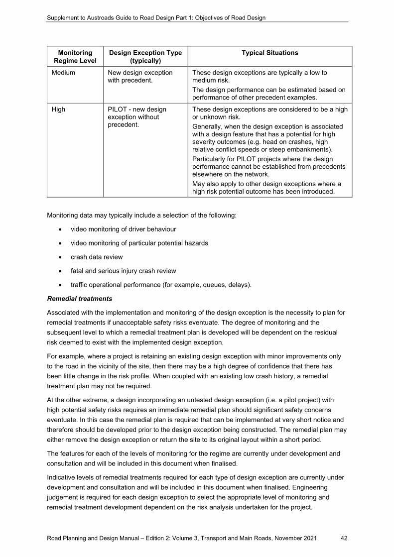
Supplement to Austroads Guide to Road Design Part 1: Objectives of Road Design
Road Planning and Design Manual – Edition 2: Volume 3, Transport and Main Roads, November 2021 42
Monitoring Regime Level
Design Exception Type (typically)
Typical Situations
Medium New design exception with precedent.
These design exceptions are typically a low to medium risk. The design performance can be estimated based on performance of other precedent examples.
High PILOT - new design exception without precedent.
These design exceptions are considered to be a high or unknown risk. Generally, when the design exception is associated with a design feature that has a potential for high severity outcomes (e.g. head on crashes, high relative conflict speeds or steep embankments). Particularly for PILOT projects where the design performance cannot be established from precedents elsewhere on the network. May also apply to other design exceptions where a high risk potential outcome has been introduced.
Monitoring data may typically include a selection of the following:
• video monitoring of driver behaviour
• video monitoring of particular potential hazards
• crash data review
• fatal and serious injury crash review
• traffic operational performance (for example, queues, delays).
Remedial treatments
Associated with the implementation and monitoring of the design exception is the necessity to plan for remedial treatments if unacceptable safety risks eventuate. The degree of monitoring and the subsequent level to which a remedial treatment plan is developed will be dependent on the residual risk deemed to exist with the implemented design exception.
For example, where a project is retaining an existing design exception with minor improvements only to the road in the vicinity of the site, then there may be a high degree of confidence that there has been little change in the risk profile. When coupled with an existing low crash history, a remedial treatment plan may not be required.
At the other extreme, a design incorporating an untested design exception (i.e. a pilot project) with high potential safety risks requires an immediate remedial plan should significant safety concerns eventuate. In this case the remedial plan is required that can be implemented at very short notice and therefore should be developed prior to the design exception being constructed. The remedial plan may either remove the design exception or return the site to its original layout within a short period.
The features for each of the levels of monitoring for the regime are currently under development and consultation and will be included in this document when finalised.
Indicative levels of remedial treatments required for each type of design exception are currently under development and consultation and will be included in this document when finalised. Engineering judgement is required for each design exception to select the appropriate level of monitoring and remedial treatment development dependent on the risk analysis undertaken for the project.

Supplement to Austroads Guide to Road Design Part 1: Objectives of Road Design
Road Planning and Design Manual – Edition 2: Volume 3, Transport and Main Roads, November 2021 43
Appendix B – Geotechnical investigation and design
B.1.2 Scope of guidance
Addition
The information in Appendix B of Austroads Guide to Road Design – Part 1 provides general details regarding geotechnical investigations and how road design outcomes and other design activities are influenced by site conditions, associated ground response, geological hazards and locally available materials. The Department of Transport and Main Road’s Geotechnical Design Standard – Minimum Requirements, defines the minimum geotechnical requirements which shall be met for all projects throughout Queensland.
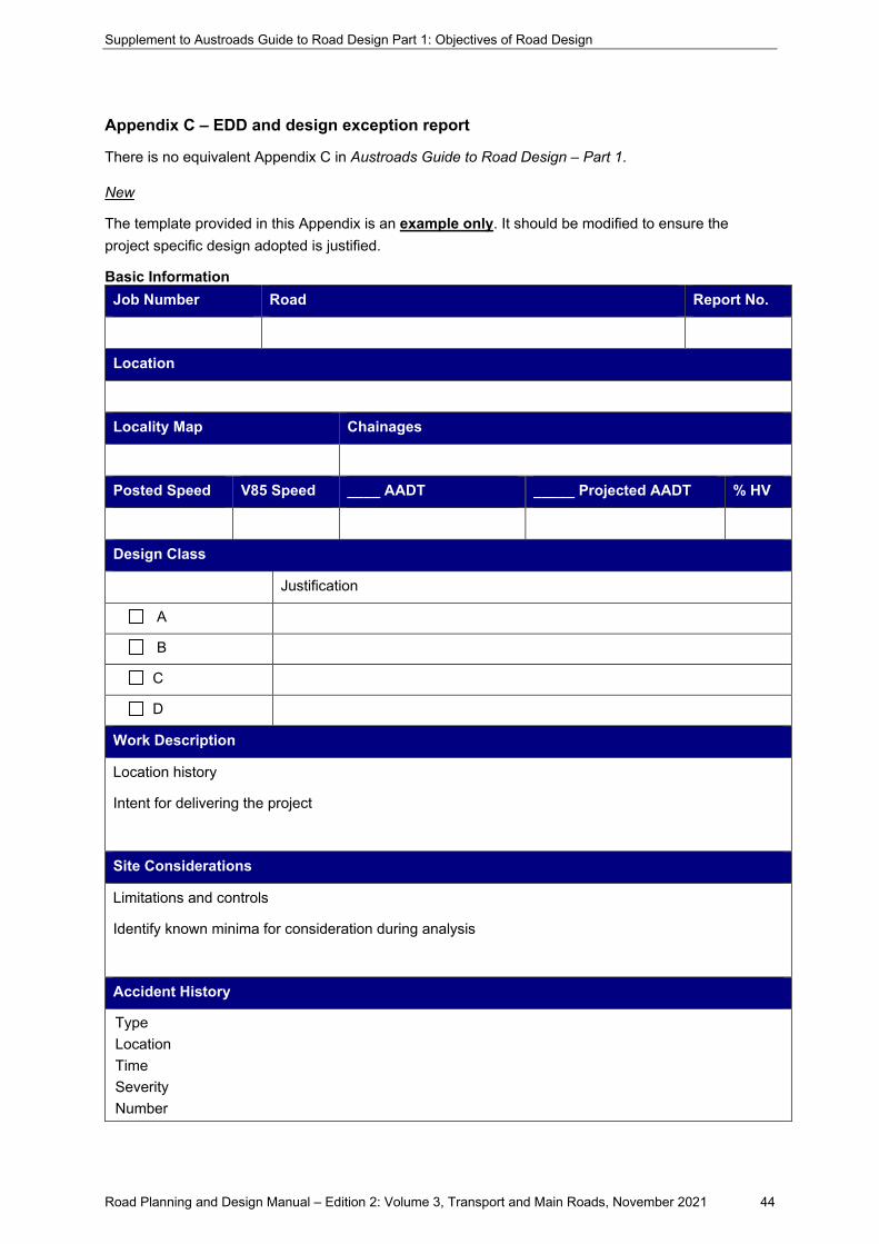
Supplement to Austroads Guide to Road Design Part 1: Objectives of Road Design
Road Planning and Design Manual – Edition 2: Volume 3, Transport and Main Roads, November 2021 44
Appendix C – EDD and design exception report
There is no equivalent Appendix C in Austroads Guide to Road Design – Part 1.
New
The template provided in this Appendix is an example only. It should be modified to ensure the project specific design adopted is justified.
Basic Information Job Number Road Report No.
Location
Locality Map Chainages
Posted Speed V85 Speed ____ AADT _____ Projected AADT % HV
Design Class
Justification
A
B
C
D
Work Description
Location history
Intent for delivering the project
Site Considerations
Limitations and controls
Identify known minima for consideration during analysis
Accident History
Type Location Time Severity Number
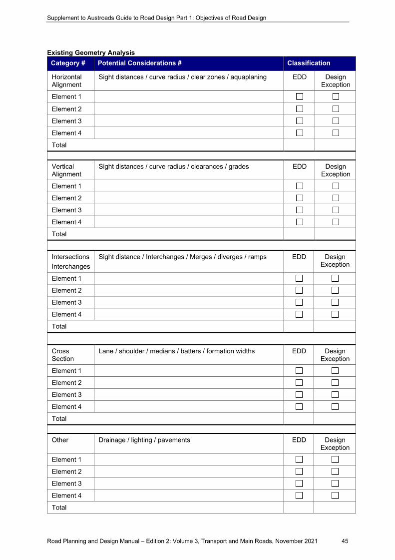
Supplement to Austroads Guide to Road Design Part 1: Objectives of Road Design
Road Planning and Design Manual – Edition 2: Volume 3, Transport and Main Roads, November 2021 45
Existing Geometry Analysis Category # Potential Considerations # Classification
Horizontal Alignment
Sight distances / curve radius / clear zones / aquaplaning EDD Design Exception
Element 1
Element 2
Element 3
Element 4
Total
Vertical Alignment
Sight distances / curve radius / clearances / grades EDD Design Exception
Element 1
Element 2
Element 3
Element 4
Total
Intersections Interchanges
Sight distance / Interchanges / Merges / diverges / ramps EDD Design Exception
Element 1
Element 2
Element 3
Element 4
Total
Cross Section
Lane / shoulder / medians / batters / formation widths EDD Design Exception
Element 1
Element 2
Element 3
Element 4
Total
Other Drainage / lighting / pavements EDD Design Exception
Element 1
Element 2
Element 3
Element 4
Total
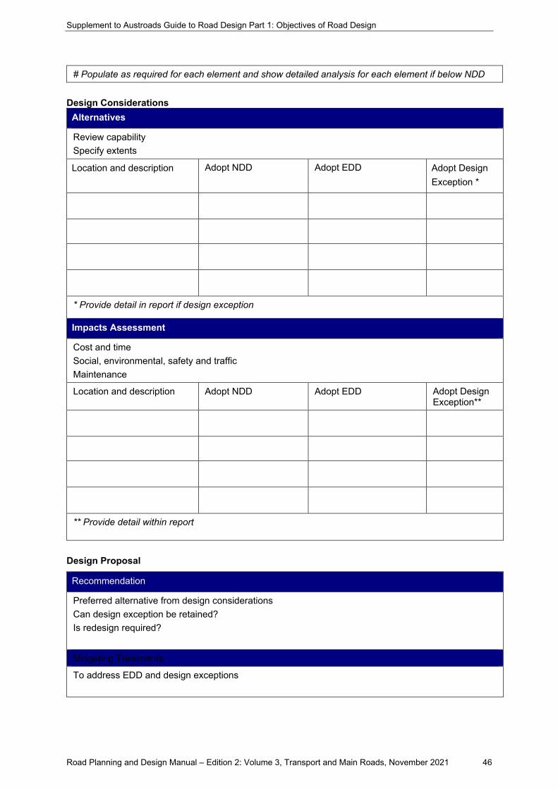
Supplement to Austroads Guide to Road Design Part 1: Objectives of Road Design
Road Planning and Design Manual – Edition 2: Volume 3, Transport and Main Roads, November 2021 46
# Populate as required for each element and show detailed analysis for each element if below NDD
Design Considerations Alternatives
Review capability Specify extents
Location and description Adopt NDD Adopt EDD Adopt Design Exception *
* Provide detail in report if design exception
Impacts Assessment
Cost and time Social, environmental, safety and traffic Maintenance
Location and description Adopt NDD Adopt EDD Adopt Design Exception**
** Provide detail within report
Design Proposal
Recommendation
Preferred alternative from design considerations Can design exception be retained? Is redesign required?
Mitigating Treatments
To address EDD and design exceptions
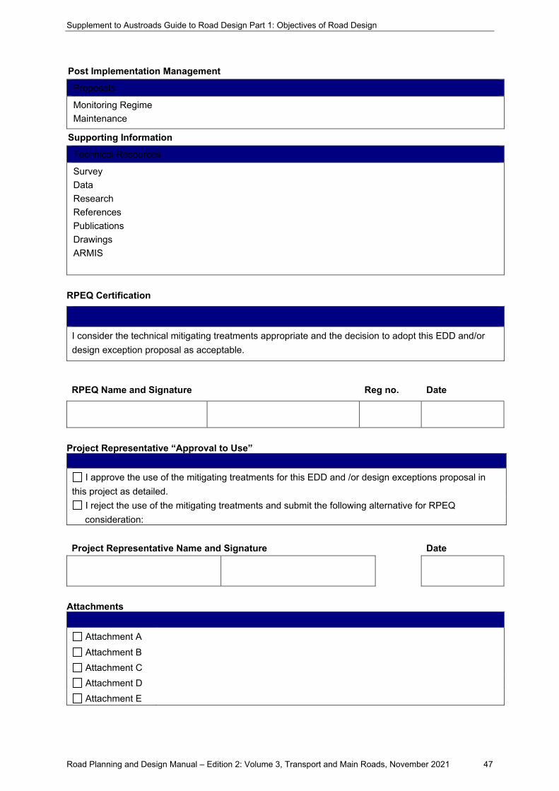
Supplement to Austroads Guide to Road Design Part 1: Objectives of Road Design
Road Planning and Design Manual – Edition 2: Volume 3, Transport and Main Roads, November 2021 47
Post Implementation Management
Proposals
Monitoring Regime Maintenance
Supporting Information
Technical Resources
Survey Data Research References Publications Drawings ARMIS
RPEQ Certification
I consider the technical mitigating treatments appropriate and the decision to adopt this EDD and/or design exception proposal as acceptable.
RPEQ Name and Signature Reg no. Date
Project Representative “Approval to Use”
I approve the use of the mitigating treatments for this EDD and /or design exceptions proposal in this project as detailed.
I reject the use of the mitigating treatments and submit the following alternative for RPEQ consideration:
Project Representative Name and Signature Date
Attachments
Attachment A Attachment B Attachment C Attachment D Attachment E

Related Documents