Supplement Infinity ® Acute Care System System Integration WARNING For a full understanding of the performance characteristics of the system integration capability, the user should carefully read this supplement and the related instructions for use before using the associated devices.

Welcome message from author
This document is posted to help you gain knowledge. Please leave a comment to let me know what you think about it! Share it to your friends and learn new things together.
Transcript
Supplement
Infinity® Acute Care System
System IntegrationWARNING
For a full understanding of the performance characteristics of the system integration capability, the user should carefully read this supplement and the related instructions for use before using the associated devices.

Supplement – Infinity® Acute Care System – System Integration 3
Trademarks
Trademark Trademark owner
Infinity® Dräger

4 Supplement – Infinity® Acute Care System – System Integration
This page has been left blank intentionally.

Supplement – Infinity® Acute Care System – System Integration 5
Contents
Contents
Introduction. . . . . . . . . . . . . . . . . . . . . . . . . . . . . . . . . . . . . . . . . . . . . . . . . . . . . . . . . . . . . . . . . . . . . . 7
Content of this document . . . . . . . . . . . . . . . . . . . . . . . . . . . . . . . . . . . . . . . . . . . . . . . . . . . . . . . . . . . . 7Illustrations . . . . . . . . . . . . . . . . . . . . . . . . . . . . . . . . . . . . . . . . . . . . . . . . . . . . . . . . . . . . . . . . . . . . 7
Workplace Functionality . . . . . . . . . . . . . . . . . . . . . . . . . . . . . . . . . . . . . . . . . . . . . . . . . . . . . . . . . . . 7
Examples of workplace functions . . . . . . . . . . . . . . . . . . . . . . . . . . . . . . . . . . . . . . . . . . . . . . . . . . . . . . 8Common audio pause. . . . . . . . . . . . . . . . . . . . . . . . . . . . . . . . . . . . . . . . . . . . . . . . . . . . . . . . . . . . 8Patient data import . . . . . . . . . . . . . . . . . . . . . . . . . . . . . . . . . . . . . . . . . . . . . . . . . . . . . . . . . . . . . . 8Display shared data . . . . . . . . . . . . . . . . . . . . . . . . . . . . . . . . . . . . . . . . . . . . . . . . . . . . . . . . . . . . . 8Time synchronization . . . . . . . . . . . . . . . . . . . . . . . . . . . . . . . . . . . . . . . . . . . . . . . . . . . . . . . . . . . . 8Data export . . . . . . . . . . . . . . . . . . . . . . . . . . . . . . . . . . . . . . . . . . . . . . . . . . . . . . . . . . . . . . . . . . . . 8
Service-oriented Device Connectivity . . . . . . . . . . . . . . . . . . . . . . . . . . . . . . . . . . . . . . . . . . . . . . . . 9
System integration and IACS . . . . . . . . . . . . . . . . . . . . . . . . . . . . . . . . . . . . . . . . . . . . . . . . . . . . . . . . . 9
Target user groups . . . . . . . . . . . . . . . . . . . . . . . . . . . . . . . . . . . . . . . . . . . . . . . . . . . . . . . . . . . . . . . . . 10Description of target groups . . . . . . . . . . . . . . . . . . . . . . . . . . . . . . . . . . . . . . . . . . . . . . . . . . . . . . . 10
Clinical user. . . . . . . . . . . . . . . . . . . . . . . . . . . . . . . . . . . . . . . . . . . . . . . . . . . . . . . . . . . . . . . . . 10Reprocessing personnel . . . . . . . . . . . . . . . . . . . . . . . . . . . . . . . . . . . . . . . . . . . . . . . . . . . . . . . 10Service personnel . . . . . . . . . . . . . . . . . . . . . . . . . . . . . . . . . . . . . . . . . . . . . . . . . . . . . . . . . . . . 10
Integrated system ID . . . . . . . . . . . . . . . . . . . . . . . . . . . . . . . . . . . . . . . . . . . . . . . . . . . . . . . . . . . . . . 11
Important safety measures during clinical use . . . . . . . . . . . . . . . . . . . . . . . . . . . . . . . . . . . . . . . . . . . . 12
Important safety measures during configuration . . . . . . . . . . . . . . . . . . . . . . . . . . . . . . . . . . . . . . . . . . 12
Device combinations . . . . . . . . . . . . . . . . . . . . . . . . . . . . . . . . . . . . . . . . . . . . . . . . . . . . . . . . . . . . . . 14
Possible device configurations . . . . . . . . . . . . . . . . . . . . . . . . . . . . . . . . . . . . . . . . . . . . . . . . . . . . . . . . 14Device configuration 1 . . . . . . . . . . . . . . . . . . . . . . . . . . . . . . . . . . . . . . . . . . . . . . . . . . . . . . . . . . . 14Device configuration 2 . . . . . . . . . . . . . . . . . . . . . . . . . . . . . . . . . . . . . . . . . . . . . . . . . . . . . . . . . . . 15Device configuration 3 . . . . . . . . . . . . . . . . . . . . . . . . . . . . . . . . . . . . . . . . . . . . . . . . . . . . . . . . . . . 16
System Integration Functions . . . . . . . . . . . . . . . . . . . . . . . . . . . . . . . . . . . . . . . . . . . . . . . . . . . . . . . 18
System integration icon display . . . . . . . . . . . . . . . . . . . . . . . . . . . . . . . . . . . . . . . . . . . . . . . . . . . . . . . 18
Data and settings monitoring . . . . . . . . . . . . . . . . . . . . . . . . . . . . . . . . . . . . . . . . . . . . . . . . . . . . . . . . . 19
Alarm status information sent to other SDC devices . . . . . . . . . . . . . . . . . . . . . . . . . . . . . . . . . . . . . . . 19
Values, waveforms and settings from other SDC devices received and displayed . . . . . . . . . . . . . . . . 19
Workplace time and other functions are synchronized. . . . . . . . . . . . . . . . . . . . . . . . . . . . . . . . . . . . . . 19Workplace time is synchronized . . . . . . . . . . . . . . . . . . . . . . . . . . . . . . . . . . . . . . . . . . . . . . . . . . . . 19Color scheme . . . . . . . . . . . . . . . . . . . . . . . . . . . . . . . . . . . . . . . . . . . . . . . . . . . . . . . . . . . . . . . . . . 20
Contents
6 Supplement – Infinity® Acute Care System – System Integration
CBM . . . . . . . . . . . . . . . . . . . . . . . . . . . . . . . . . . . . . . . . . . . . . . . . . . . . . . . . . . . . . . . . . . . . . . . . . 20OR mode . . . . . . . . . . . . . . . . . . . . . . . . . . . . . . . . . . . . . . . . . . . . . . . . . . . . . . . . . . . . . . . . . . . . . 20Analysis tool . . . . . . . . . . . . . . . . . . . . . . . . . . . . . . . . . . . . . . . . . . . . . . . . . . . . . . . . . . . . . . . . . . . 20Common workplace audio pause . . . . . . . . . . . . . . . . . . . . . . . . . . . . . . . . . . . . . . . . . . . . . . . . . . . 20Patient admission and demographic data sent to other SDC devices . . . . . . . . . . . . . . . . . . . . . . . 20
Configuring SDC System Integration . . . . . . . . . . . . . . . . . . . . . . . . . . . . . . . . . . . . . . . . . . . . . . . . . 21
Steps for configuring the Integrated system ID . . . . . . . . . . . . . . . . . . . . . . . . . . . . . . . . . . . . . . . . . . . 21
Steps for configuring the SDC Time . . . . . . . . . . . . . . . . . . . . . . . . . . . . . . . . . . . . . . . . . . . . . . . . . . . . 22
Steps for configuring the Shared system functions . . . . . . . . . . . . . . . . . . . . . . . . . . . . . . . . . . . . . . . . 22
Biomed > Country tab . . . . . . . . . . . . . . . . . . . . . . . . . . . . . . . . . . . . . . . . . . . . . . . . . . . . . . . . . . . . . 23
Biomed setup - Country specific settings . . . . . . . . . . . . . . . . . . . . . . . . . . . . . . . . . . . . . . . . . . . . . . . . 24
Biomed > System integration > Integrated system ID tab . . . . . . . . . . . . . . . . . . . . . . . . . . . . . . . . 25
Biomed setup - System integration - Integrated system ID . . . . . . . . . . . . . . . . . . . . . . . . . . . . . . . . . . 26
Biomed > System integration > Shared system functions tab. . . . . . . . . . . . . . . . . . . . . . . . . . . . . 27
Biomed setup - System integration - Shared system functions . . . . . . . . . . . . . . . . . . . . . . . . . . . . . . . 28
Technical Information . . . . . . . . . . . . . . . . . . . . . . . . . . . . . . . . . . . . . . . . . . . . . . . . . . . . . . . . . . . . . 29
Certificates . . . . . . . . . . . . . . . . . . . . . . . . . . . . . . . . . . . . . . . . . . . . . . . . . . . . . . . . . . . . . . . . . . . . . . . 29
Data interfaces . . . . . . . . . . . . . . . . . . . . . . . . . . . . . . . . . . . . . . . . . . . . . . . . . . . . . . . . . . . . . . . . . . . . 29
SDC LAN interface . . . . . . . . . . . . . . . . . . . . . . . . . . . . . . . . . . . . . . . . . . . . . . . . . . . . . . . . . . . . . . . . . 30Service-oriented Device Connectivity (SDC) . . . . . . . . . . . . . . . . . . . . . . . . . . . . . . . . . . . . . . . . . . 30Service . . . . . . . . . . . . . . . . . . . . . . . . . . . . . . . . . . . . . . . . . . . . . . . . . . . . . . . . . . . . . . . . . . . . . . . 31Required characteristics . . . . . . . . . . . . . . . . . . . . . . . . . . . . . . . . . . . . . . . . . . . . . . . . . . . . . . . . . . 32Requirements for the electrical characteristics of connected devices and networks . . . . . . . . . . . . 33Hazardous situations . . . . . . . . . . . . . . . . . . . . . . . . . . . . . . . . . . . . . . . . . . . . . . . . . . . . . . . . . . . . 33

Supplement – Infinity® Acute Care System – System Integration 7
Introduction
Introduction
Content of this document
This supplement contains updates to the instructions for use (IFU) for the Infinity Acute Care System (IACS) VG7.1. Combine this supplement with the following documents to form the complete set of IFUs:
– Instructions for use Infinity Acute Care System Monitoring Applications Software VG7.n
– Instructions for use Infinity Acute Care System Monitoring accessories Software VG7.n
– Instructions for use Infinity Acute Care System Infinity M540 patient monitor Software VG7.n
– Supplement Infinity Acute Care System Software VG7.n
Illustrations
Illustrations of products and screen content in this document may differ from the actual products depending on configuration and design.
Workplace Functionality
Workplace functionality (WPF) begins with an integrated system that combines different devices at a workplace. This integration allows sharing of information and functions between devices at the workplace. Data from one device can be displayed on other devices in the same workplace. A single user interaction at one device can trigger shared functions affecting several devices at the workplace. The resulting effects on the patient from all devices should be considered by the user.
Some shared functions only work in one direction while others work in both directions, which means devices affect each other mutually. Functions that affect the operation of one device must be configured on the affected device by service personnel. Consequently functions working in both directions must be configured on all involved devices.
Awareness of potential patient risks require the users to understand the relevance of the correct Integrated system ID, which must correspond to the unique name of the workplace. Each hospital should have a naming scheme in place that specifies a proper Integrated system ID for each workplace in the hospital.
Shared functions are not necessarily realized by a point to point cable connection, but by the network connection. Here, the Integrated system ID is of particular importance because devices with the same Integrated System ID are assigned to the same workplace and will share data and functions.

Workplace Functionality
8 Supplement – Infinity® Acute Care System – System Integration
Examples of workplace functions
Common audio pause
The various devices of the workplace each have their own audio pause key to temporarily mute the acoustic device alarms. In the integrated system, the audio pause function is synchronized across all devices of the workplace. In situations where multiple devices may cause an alarm, this reduces the number of required user interactions to silence the workplace.
Patient data import
On the hemodynamic monitor, admission, discharge and transfer (ADT) patient data can be taken over the network (get HIS) or entered by manual input in the patient dialog (e.g., size, age, weight, patient category). This information is relayed to the therapy device at the common workplace to support proper and consistent device settings for therapy and alarms of the various devices configured for the same workplace. This action is supported only in this direction, not in both directions.
Display shared data
On the hemodynamic monitor, waveforms and parameter values from the connected ventilator or anesthesia machine of the same workplace can be displayed.
Time synchronization
The various devices synchronize their device time with a central time server on the network (NTP). This achieves a consistent time setting across all devices of the workstation and supports consistent and correct documentation.
Data export
The data (settings, physiological values, alarms) from devices, such as hemodynamic monitors, ventilators, or anesthesia machines, is made available on the network for use by other devices or applications (e.g. HIS, HL7, PDMS and others).

Supplement – Infinity® Acute Care System – System Integration 9
Service-oriented Device Connectivity
Service-oriented Device Connectivity
Service-oriented Device Connectivity (SDC) defines a communication architecture to establish distributed systems of medical devices in clinical environments, for example, high-acuity environments. The protocol is built on the principles of service-oriented medical device architecture (SOMDA) and is modeled after ISO/IEEE 11073. SDC-enabled devices facilitate interoperability across Dräger SDC-compatible products by allowing the request of unidirectional data and/or the remote control of pre-determined medical device functionality in a safe manner. SDC provides System Integration functionality and is intended for use by healthcare professionals in a hospital environment.
System Integration and IACS
System Integration allows the IACS physiologic monitor (M540 device) and the IACS Medical Cockpit to share information, control specific functions, and synchronize specific operations with other Dräger-certified SDC devices in a medical device or IT system.
In combination with other Dräger-certified SDC devices, the physiologic monitor:
– Provides physiologic monitoring data and settings to other devices.
– Provides alarm status information to other devices.
– Receives network time commands.
– Provides a means to configure a workplace for point-to-point communication with other devices utiliz-ing the device’s unique Integrated system ID.
– Hospital ID (Hospital name)
– Department ID (Care unit label)
– Workstation ID (Device label)
Refer to "Integrated system ID" on page 11 for more information.
– Receives and displays values, waveforms, and settings from other devices in the same workplace.
– Synchronizes specific operations with other devices in the same workplace including:
– Sharing of color scheme between devices
– Synchronizes the cardiac bypass mode (CBM) to the respective mode of a Dräger-certified SDC anesthesia machine configured for the same workplace and changing its alarm behavior accord-ingly.
– Switch to operating room (OR) mode alarm behavior as soon as an Dräger-certified SDC anesthe-sia device configured for the same workplace is detected.
– Opens the analysis tool presentation when a Dräger-certified SDC anesthesia device configured for the same workplace detects that the “procedures” dialogue is opened.
– Sharing of workplace common audio pause.
Service-oriented Device Connectivity
10 Supplement – Infinity® Acute Care System – System Integration
– Provides patient admission and demographic data to other devices in the same workplace.
– Provides time synchronization commands to other devices in the same workplace.
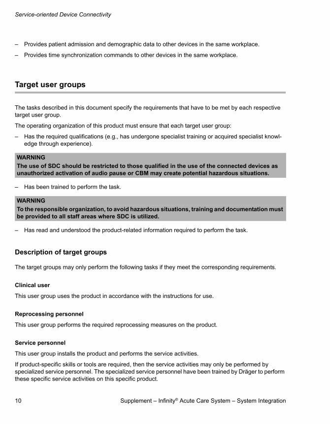
Target user groups
The tasks described in this document specify the requirements that have to be met by each respective target user group.
The operating organization of this product must ensure that each target user group:
– Has the required qualifications (e.g., has undergone specialist training or acquired specialist knowl-edge through experience).
– Has been trained to perform the task.
– Has read and understood the product-related information required to perform the task.
Description of target groups
The target groups may only perform the following tasks if they meet the corresponding requirements.
Clinical user
This user group uses the product in accordance with the instructions for use.
Reprocessing personnel
This user group performs the required reprocessing measures on the product.
Service personnel
This user group installs the product and performs the service activities.
If product-specific skills or tools are required, then the service activities may only be performed by specialized service personnel. The specialized service personnel have been trained by Dräger to perform these specific service activities on this specific product.
WARNING
The use of SDC should be restricted to those qualified in the use of the connected devices as unauthorized activation of audio pause or CBM may create potential hazardous situations.
WARNING
To the responsible organization, to avoid hazardous situations, training and documentation must be provided to all staff areas where SDC is utilized.
Supplement – Infinity® Acute Care System – System Integration 11
Integrated system ID
Integrated system ID
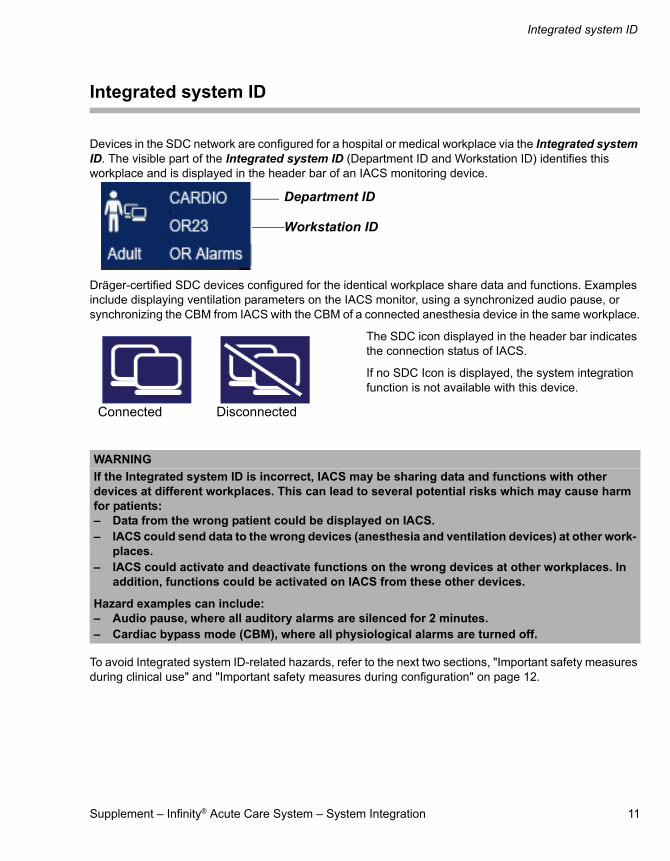
Devices in the SDC network are configured for a hospital or medical workplace via the Integrated system ID. The visible part of the Integrated system ID (Department ID and Workstation ID) identifies this workplace and is displayed in the header bar of an IACS monitoring device.
Dräger-certified SDC devices configured for the identical workplace share data and functions. Examples include displaying ventilation parameters on the IACS monitor, using a synchronized audio pause, or synchronizing the CBM from IACS with the CBM of a connected anesthesia device in the same workplace.
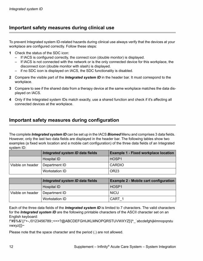
The SDC icon displayed in the header bar indicates the connection status of IACS.
If no SDC Icon is displayed, the system integration function is not available with this device.
To avoid Integrated system ID-related hazards, refer to the next two sections, "Important safety measures during clinical use" and "Important safety measures during configuration" on page 12.
WARNING
If the Integrated system ID is incorrect, IACS may be sharing data and functions with other devices at different workplaces. This can lead to several potential risks which may cause harm for patients:– Data from the wrong patient could be displayed on IACS.– IACS could send data to the wrong devices (anesthesia and ventilation devices) at other work-
places.– IACS could activate and deactivate functions on the wrong devices at other workplaces. In
addition, functions could be activated on IACS from these other devices.
Hazard examples can include:– Audio pause, where all auditory alarms are silenced for 2 minutes.– Cardiac bypass mode (CBM), where all physiological alarms are turned off.
Department ID
Workstation ID
Connected Disconnected
Integrated system ID
12 Supplement – Infinity® Acute Care System – System Integration
Important safety measures during clinical use
To prevent Integrated system ID-related hazards during clinical use always verify that the devices at your workplace are configured correctly. Follow these steps:
1 Check the status of the SDC icon:– If IACS is configured correctly, the connect icon (double monitor) is displayed.– If IACS is not connected with the network or is the only connected device for this workplace, the
disconnect icon (double monitor with slash) is displayed.– if no SDC icon is displayed on IACS, the SDC functionality is disabled.
2 Compare the visible part of the Integrated system ID in the header bar. It must correspond to the workplace.
3 Compare to see if the shared data from a therapy device at the same workplace matches the data dis-played on IACS.
4 Only if the Integrated system IDs match exactly, use a shared function and check if it's affecting all connected devices at the workplace.
Important safety measures during configuration
The complete Integrated system ID can be set up in the IACS Biomed Menu and comprises 3 data fields. However, only the last two data fields are displayed in the header bar. The following tables show two examples (a fixed work location and a mobile cart configuration) of the three data fields of an Integrated system ID:
Each of the three data fields of the Integrated system ID is limited to 7 characters. The valid characters for the Integrated system ID are the following printable characters of the ASCII character set on an English keyboard: !"#$%&'()*+-,/0123456789:;<=>?@ABCDEFGHIJKLMNOPQRSTUVWXYZ[\]^_`abcdefghijklmnopqrstuvwxyz{|}~
Please note that the space character and the period (.) are not allowed.
Integrated system ID data fields Example 1 - Fixed workplace location
Hospital ID HOSP1
Visible on header Department ID CARDIO
Workstation ID OR23
Integrated system ID data fields Example 2 - Mobile cart configuration
Hospital ID HOSP1
Visible on header Department ID NICU
Workstation ID CART_1

Supplement – Infinity® Acute Care System – System Integration 13
Integrated system ID
To ensure correct configuration of IACS, take measures to choose appropriate Integrated system IDs. Dräger recommends developing a naming scheme for all workplaces throughout the hospital based on the requirements for appropriate Integrated system IDs:
– The Integrated system ID should correspond to the physical location of the workplace (see "Example 1 - Fixed workplace location" on page 12).
– In case IACS is being used in a fixed combination with a therapy device on a trolley, the Integrated System ID should reflect this (see "Example 2 - Mobile cart configuration" on page 12).
– The part of the Integrated system ID displayed in the header bar (Department ID and Workstation ID) must be unique for a workplace throughout the hospital, and short enough to be fully displayed in the header bar.
– Avoid characters which can be easily confused. For example, avoid using the number “1” (one) versus the letter “I”, or avoid using the number “0” (zero) versus the letter “O”.
– Only turn on shared functions if all the user groups of the connected devices are properly trained for using the shared functions.

Device combinations
14 Supplement – Infinity® Acute Care System – System Integration
Device combinations
This software can be operated in combination with other Dräger-certified SDC devices. Follow the accompanying documentation for each individual device.
Possible device configurations
The IACS patient monitoring system, with required software installed, can be used in the 3 device configurations that define typical hospital situations, as shown on the following pages.
Device configuration 1
The IACS patient monitoring system, with the required software installed, and Dräger-certified SDC therapy device are mounted on a trolley (with an optional Dräger Connectivity Converter CC300).
With this device configuration the IACS patient monitoring system always uses the Integrated system ID that was configured for this device configuration. Even after temporary power supply failures or after
CC300
IACS monitoring device
Dräger-certified SDC therapy device

Supplement – Infinity® Acute Care System – System Integration 15
Device combinations
moving the trolley to a different operating location, the IACS will continue to use this Integrated system ID.
The IACS montoring device must be visibly labeled with the assigned Integrated system ID. In this case the Integrated system ID designates an equipment configuration (e.g., HOSP1/COMBI/CART1) and not an operating location (e.g., Operating Room 1). The Integrated system ID must be identical with the Integrated system ID of the associated Dräger-certified SDC therapy device (optional with CC300 Connectivity Converter) to confirm the location.
It is not possible to transfer an Integrated system ID from a switch in a fixed location with this device configuration.
Device configuration 2
With the required software installed, the IACS patient monitoring system and optional Dräger Connectivity Converter CC300 are in an operating location with the Dräger-certified SDC therapy device.
With this device configuration the IACS monitoring device always uses the Integrated system ID that was
CC300
IACS monitoring device
Dräger-certified SDC therapy device

Device combinations
16 Supplement – Infinity® Acute Care System – System Integration
configured for this location. No user interaction is required, not even in the event of a temporary power supply failure or after connecting a different therapy device. In this case the Integrated system ID designates an operating location (e.g., HOSP1/CARDIO/ OR22) and not an equipment configuration.
The Integrated system ID must also be identical to the Integrated system ID of the associated connectivity converter CC300.
Device configuration 3
The IACS patient monitoring system, with the required software installed, is mounted in a fixed location (e.g., on a wall) and the Dräger-certified SDC therapy device is mounted on a trolley, with an optional Dräger Connectivity Converter CC300.
The same Integrated system ID must be configured and validated by the service personnel for the IACS patient monitoring system and the Dräger-certified SDC therapy device (with optional connectivity converter CC300) in order to enable communication with the associated monitoring device.
If the IACS power supply is interrupted, the Integrated system ID must be validated again in the IACS system configuration. The Integrated system ID must be setup for initial operation and then updated after the device has been moved to a different operating location.
CC300
Dräger-certified SDC therapy device
IACS monitoring device
Supplement – Infinity® Acute Care System – System Integration 17
Device combinations
In this case the Integrated system ID designates the operating location of the permanently located Dräger-certified SDC monitor (e.g., HOSP1/CARDIO/OR22) and not an equipment configuration. LLDP technology is not supported by IACS. The integrated system ID must be manually configured in all physical configurations.
WARNING
When adding or replacing an IACS device in an integrated system (either in a fixed workplace location or mounted to the trolley of the anesthesia device) update the Integrated system ID at the time of installation.
WARNING
Only device configurations 1, 2 and 3, described in the section "Possible device configurations", are allowed. When installing IACS in a different configuration, e.g., on a rolling stand or table, SDC must be turned off.

System Integration Functions
18 Supplement – Infinity® Acute Care System – System Integration
System Integration Functions
When the required IACS software is installed, the following System Integration functions are available:
– "System Integration icon display"
– "Data and settings monitoring"
– "Alarm status information sent to other SDC devices"
– "Values, waveforms and settings from other SDC devices received and displayed"
– "Workplace time and other functions are synchronized"
– "Patient admission and demographic data sent to other SDC devices"
System Integration icon display
When the System Integration option is installed (locked), an icon is displayed on the header bar.
The Integrated system ID is displayed in the headline next to the icon. In order to have combined system function with Draeger-certified SDC Therapy devices the Integrated system IDs of both devices must be identical. Changes to the Integrated system ID can only be done by specialized personnel.
The System Integration function might not be available when the System Integration icon is displayed with a strike-through symbol.
Supplement – Infinity® Acute Care System – System Integration 19
System Integration Functions
Data and settings monitoring
The IACS monitoring device, with the required software, sends physiological data settings and measurements to other devices on the network.
Alarm status information sent to other SDC devices
The IACS monitoring device, with the required software, sends alarm status information to other Dräger-certified SDC devices on the network.
Values, waveforms and settings from other SDC devices received and displayed
Values, waveforms and settings from connected Dräger-certified SDC devices at the same workplace can be received and displayed the same way as if the data would have been acquired via Medibus/Medibus.X. This function is described in detail in the main IACS IfU (see Instructions for use Infinity Acute Care System Monitoring Applications Software VG7.n).
Workplace time and other functions are synchronized
Workplace time is synchronized
The IACS monitoring device, with the required software, receives a Network Time Protocol (NTP) clock synchronization and time zone from the Infinity Gateway, and may send device time to connected Dräger-certified SDC devices located at the same workplace.
WARNING
– Do not rely on IACS as a substitution for a hospital distributed alarm system. – SDC information has not been validated to perform as a hospital alarm distribution system.– Hospital personnel should stay within a limited area where they can be certain to hear the
alarms issued by the Dräger-certified SDC device.

System Integration Functions
20 Supplement – Infinity® Acute Care System – System Integration
Color scheme
The IACS monitoring device, with the required software, can be enabled to synchronize the color scheme with another Dräger-certified SDC device of the same workplace (same Integrated system ID) which sends out this command.
CBM
The IACS monitoring device, with the required software, can be enabled to respond to the CBM mode request from another Dräger-certified SDC device located in the same workplace and using same Integrated system ID.
OR mode
The IACS monitoring device, with the required software, can be enabled to synchronize the alarm behavior to Operating Room (OR) mode from another Dräger- certified SDC device in the same workplace (using the same Integrated system ID) (anesthesia devices only).
Analysis tool
The IACS patient monitoring system, with the required software installed, can be enabled to open the analysis tool presentation synchronized with the opening of a recruitment dialogue on a Dräger-certified SDC therapy device with connectivity converter CC300, which sends out this command.
Common workplace audio pause
The IACS patient monitoring system, with the required software installed, can be enabled to synchronize its audio pause state with the audio pause state of the connected Dräger-certified SDC devices when configured to the same hospital location.
Patient admission and demographic data sent to other SDC devices
The IACS patient monitoring system, with the required software installed, provides the patient demographic data taken from the network via the “Get HIS” function or after manual input to the connected Dräger-certified SDC device of the same workplace in order to harmonize patient information across the devices of the same workplace.
WARNING
Audio pause of other devices are not automatically terminated if the audio pause of the SDC device times out.
Supplement – Infinity® Acute Care System – System Integration 21
Configuring SDC System Integration
Configuring SDC System Integration
Steps for configuring the Integrated system ID
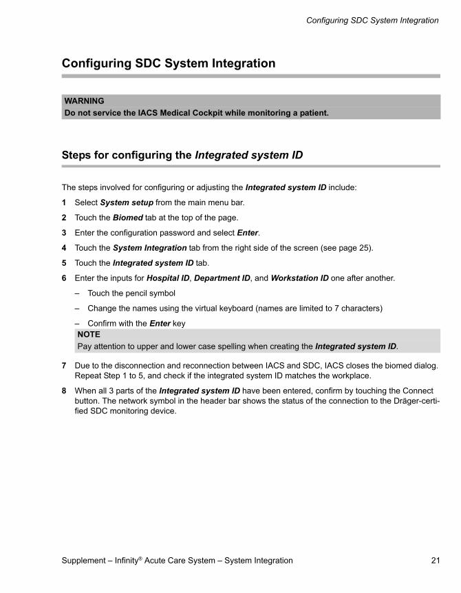
The steps involved for configuring or adjusting the Integrated system ID include:
1 Select System setup from the main menu bar.
2 Touch the Biomed tab at the top of the page.
3 Enter the configuration password and select Enter.
4 Touch the System Integration tab from the right side of the screen (see page 25).
5 Touch the Integrated system ID tab.
6 Enter the inputs for Hospital ID, Department ID, and Workstation ID one after another.
– Touch the pencil symbol
– Change the names using the virtual keyboard (names are limited to 7 characters)
– Confirm with the Enter key
7 Due to the disconnection and reconnection between IACS and SDC, IACS closes the biomed dialog. Repeat Step 1 to 5, and check if the integrated system ID matches the workplace.
8 When all 3 parts of the Integrated system ID have been entered, confirm by touching the Connect button. The network symbol in the header bar shows the status of the connection to the Dräger-certi-fied SDC monitoring device.
WARNING
Do not service the IACS Medical Cockpit while monitoring a patient.
NOTE
Pay attention to upper and lower case spelling when creating the Integrated system ID.

Configuring SDC System Integration
22 Supplement – Infinity® Acute Care System – System Integration
Steps for configuring the SDC Time
The steps involved for configuring or adjusting the SDC Time include:
1 Select System setup from the main menu bar.
2 Touch the Biomed tab at the top of the page.
3 Enter the configuration password and select Enter.
4 Touch the Country tab from the right side of the screen (see page 23).
5 To activate the SDC Time, touch the On button.
Steps for configuring the Shared system functions
The steps involved for configuring or adjusting the Shared system functions include:
1 Select System setup from the main menu bar (see page 22).
2 Touch the Biomed tab at the top of the page.
3 Enter the configuration password and select Enter.
4 Touch the System Integration tab from the right side of the screen (see page 25).
5 Touch the Shared system functions tab (see page 27).
6 If necessary, make additional settings for the workplace using the Auto button to enable the function or the Manual button to disable the function.
The following sections describe the screens and fields needed to configure the System Integration settings.
NOTE
After a change to the setting SDC Time, the CC300 should be restarted to ensure the correct time source is used.

Supplement – Infinity® Acute Care System – System Integration 23
Biomed > Country tab
Biomed > Country tab
Once you have accessed the Biomed page, select the Country tab from the right side of the page and click the On button to enable the SDC Time and disable the local IACS time and date controls.
The Country tab parameters are described in the section, "Biomed setup - Country specific settings" on page 24.
NOTE
If the System Integration option is disabled, there will be a Time zone option displayed underneath the Language option.
When the System Integration option is enabled, the Time zone option will not be displayed on the Country tab.
System setup X
Screen setup Alarms Recordings/Reports
Biomed Profiles
Units of measure
Patient monitor
Nameservice
Networksetup
Printer setup
Recordersetup
Service
System integration
IT setup
Language English (United States)
SDC Time
Time
OffOn
Day Month Year
Apply
24 August 2017
12 19
Country
Biomed tab
Country tabLanguage
SDC Time
Time
Biomed > Country tab
24 Supplement – Infinity® Acute Care System – System Integration
Biomed setup - Country specific settings
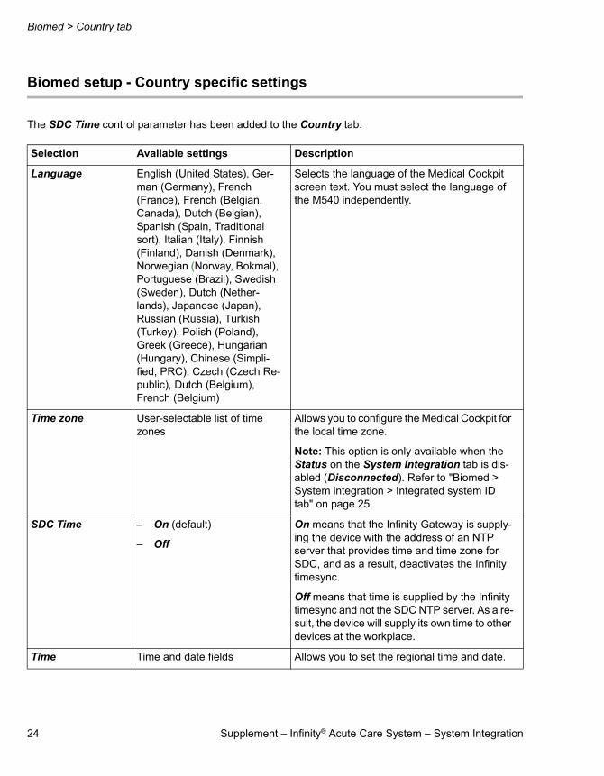
The SDC Time control parameter has been added to the Country tab.
Selection Available settings Description
Language English (United States), Ger-man (Germany), French (France), French (Belgian, Canada), Dutch (Belgian), Spanish (Spain, Traditional sort), Italian (Italy), Finnish (Finland), Danish (Denmark), Norwegian (Norway, Bokmal), Portuguese (Brazil), Swedish (Sweden), Dutch (Nether-lands), Japanese (Japan), Russian (Russia), Turkish (Turkey), Polish (Poland), Greek (Greece), Hungarian (Hungary), Chinese (Simpli-fied, PRC), Czech (Czech Re-public), Dutch (Belgium), French (Belgium)
Selects the language of the Medical Cockpit screen text. You must select the language of the M540 independently.
Time zone User-selectable list of time zones
Allows you to configure the Medical Cockpit for the local time zone.
Note: This option is only available when the Status on the System Integration tab is dis-abled (Disconnected). Refer to "Biomed > System integration > Integrated system ID tab" on page 25.
SDC Time – On (default)
– Off
On means that the Infinity Gateway is supply-ing the device with the address of an NTP server that provides time and time zone for SDC, and as a result, deactivates the Infinity timesync.
Off means that time is supplied by the Infinity timesync and not the SDC NTP server. As a re-sult, the device will supply its own time to other devices at the workplace.
Time Time and date fields Allows you to set the regional time and date.

Supplement – Infinity® Acute Care System – System Integration 25
Biomed > System integration > Integrated system ID tab
Biomed > System integration > Integrated system ID tab
Once you have accessed the Biomed page, select the System Integration tab from the right side of the page, and then select the Integrated system ID tab on the top of the page.
The Integrated system ID tab parameters are described in the section, "Biomed setup - System integration - Integrated system ID" on page 26.
System setup X
Screen setup Alarms Recordings/Reports
Biomed Profiles
Country
Units of measure
Patient monitor
Nameservice
Networksetup
Printer setup
Recordersetup
Service
IT setup
Shared systemfunctions
Integratedsystem ID
Instruction
Status
Apply
Connect
Hospital ID
Department ID
Workstation ID
Communication with the M540 will be temporarily lost when the Apply button is pressed
In the network, there is another patient monitor with the same integrated system ID.Check the Integrated system ID.
DisconnectDisconnected
HOSP42
CU1
Bedbb
System integration
Biomed tab
SystemIntegration tab
Hospital ID
Department ID
Workstation ID
Instruction
Status
Integrated system ID tab
Biomed > System integration > Integrated system ID tab
26 Supplement – Infinity® Acute Care System – System Integration
Biomed setup - System integration - Integrated system ID
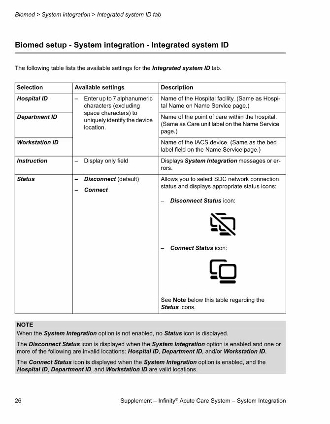
The following table lists the available settings for the Integrated system ID tab.
Selection Available settings Description
Hospital ID – Enter up to 7 alphanumeric characters (excluding space characters) to uniquely identify the device location.
Name of the Hospital facility. (Same as Hospi-tal Name on Name Service page.)
Department ID Name of the point of care within the hospital. (Same as Care unit label on the Name Service page.)
Workstation ID Name of the IACS device. (Same as the bed label field on the Name Service page.)
Instruction – Display only field Displays System Integration messages or er-rors.
Status – Disconnect (default)
– Connect
Allows you to select SDC network connection status and displays appropriate status icons:
– Disconnect Status icon:
– Connect Status icon:
See Note below this table regarding the Status icons.
NOTE
When the System Integration option is not enabled, no Status icon is displayed.
The Disconnect Status icon is displayed when the System Integration option is enabled and one or more of the following are invalid locations: Hospital ID, Department ID, and/or Workstation ID.
The Connect Status icon is displayed when the System Integration option is enabled, and the Hospital ID, Department ID, and Workstation ID are valid locations.

Supplement – Infinity® Acute Care System – System Integration 27
Biomed > System integration > Shared system functions tab
Biomed > System integration > Shared system functions tab
Once you have accessed the Biomed page, select the System Integration tab from the right side of the page, and then select the Shared system functions tab on the top of the page.
The Shared system functions tab parameters are described in the section, "Biomed setup - System integration - Shared system functions" on page 28.
System setup X
Screen setup Alarms Recordings/Reports
Biomed Profiles
Country
Units of measure
Patient monitor
Nameservice
Networksetup
Printer setup
Recordersetup
Service
IT setup
Shared system
functionsIntegratedsystem ID
Adopt OR alarms ‘Auto’ enables OR alarms whenconnected to an anesthesia device
Auto Manual
Adopt cardiac bypass Auto Manual
Adopt color scheme Auto Manual
Adopt audio pause On Off
Automatic analysis tool On Off
System integration
Biomed tab
SystemIntegration tab
Shared system functions tab
Adopt ORalarms
Adopt cardiacbypass
Adopt colorscheme
Adopt audiopause
Automaticanalysis tool

Biomed > System integration > Shared system functions tab
28 Supplement – Infinity® Acute Care System – System Integration
Biomed setup - System integration - Shared system functions
The following table lists the available settings for the Shared system functions tab.
Selection Available settings Description
Adopt OR alarms – Auto (default)
– Manual
Auto enables OR alarms when connected to an anesthesia device.
Adopt cardiac bypass
– Auto
– Manual (default)
Auto places the monitor in cardiac bypass mode when the anesthesia device enters car-diac bypass mode.
Adopt color scheme
– Auto
– Manual (default)
Auto synchronizes the color scheme used on the therapy device and the monitor.
Adopt audio pause
– On
– Off (default)
On enables the alarm acknowledgment and audio-paused state from both the therapy de-vice and the monitor when configured to the same location.
Automatic analysis tool
– On
– Off (default)
On automatically opens the analysis tool on the monitor during a recruitment maneuver on the therapy device.
NOTE
While Adopt audio pause is set to On, the Enable Remote Silence setting on the IACS is automatically set to Off, and the IACS does not respond to audio pause commands from remote devices, i.e., Infinity Central Station or remote view from another IACS.
The F1 key of an external keyboard on an IACS will only trigger an audio pause on the IACS and will not trigger an audio pause on a therapy device configured to the same location. As a result, one device can be in audio pause while the other device is not in audio pause. To corrected this situation, press the Au-dio Pause key again on either the IACS or the SDC therapy device.

Supplement – Infinity® Acute Care System – System Integration 29
Technical Information
Technical Information
Certificates
IACS is delivered with a valid SDC certificate. System Integration communication is only possible with a valid certificate. When this certificate expires, it must be renewed by specialized service personnel.
Data interfaces
In an IT network, data can be exchanged by means of wired or wireless technologies. An IT network can communicate over any data interface (e.g., RS232, LAN, USB, printer interface) that is described in standards and conventions.Connecting this device to a network that incorporates other devices or making subsequent changes to that network can lead to new risks for patients, users, and third parties.
Before the device is connected to the network or the network is changed, these risks must be identified, analyzed, and assessed by the IT representative for the hospital in accordance with the IEC 80001-1 standard (Risk Management for Medical IT Networks). Based on the results, appropriate measures must be taken.
Examples of subsequent changes to the network:
– Changing the network configuration
– Removing devices from the network
– Adding new devices to the network
– Performing upgrades or updates on devices that are connected to the network
CAUTION
A loss of network connectivity or communication with another Dräger-certified SDC device could result in the loss of patient data.

Technical Information
30 Supplement – Infinity® Acute Care System – System Integration
SDC LAN interface
Service-oriented Device Connectivity (SDC)
In combination with Dräger-certified SDC devices, SDC enables the following functions:
– Sending of measurements, waveforms, and set values to other devices
– Sending of alarm status information to other devices
– Synchronization of device states with other SDC devices:
– Color scheme
– Executing commands sent from other devices in the same workplace:
– Audio pause
– Sending commands to other devices in the same workplace:
– Audio pause
– Automatic opening of dialogs (e.g., for maneuvers)
– Providing values for demographic data sent from other devices in the same workplace
– Synchronizing the time on the device from an SDC Time source
WARNING
If an SDC therapy device is connected, then an additional Medibus.X device of the same type cannot be connected serially to an IACS patient monitoring system.
For example, if a Medibus.X Anesthesia or Ventilator is SDC-connected, then another Medibus.X Anesthesia or Ventilator connected via a serial port will be ignored.
Supplement – Infinity® Acute Care System – System Integration 31
Technical Information
When data is used from devices that are not certified by Dräger, the data is considered to be for information purposes only. Do not use this data as the sole basis for diagnostic or therapeutic decisions. Do not use this data for patient monitoring or device monitoring.
Service
In conjunction with the Dräger Service Connect Gateway or a Dräger Service computer, SDC supports the following functions:
– Using the SNMP protocol:To monitor the service status of the device, request the service status, support the installation of device software and during software downloads, configuration support, and the update of certificates.
– Using the FTP protocol (as a client):Provide support during the installation of device software and software downloads.
NOTE
All information, with the exception of the Integrated system ID, is encrypted when passed between SDC devices.
CAUTION
Connections to IT networks should be limited to only those networks where access to devices are controlled by the responsible hospital IT organization.
WARNING
Risk from communication with an unauthorized SDC device: – The operating organization should maintain a list of permissible SDC devices for
communication. – A connection should only be made with those products that are entered in this list.– Keep the list up-to-date, so that it only contains those devices that have been approved for
SDC connections.– Establish alternative communication options (e.g., MAC address filters).
WARNING
Regarding connecting to a hospital network:– Many medical devices use networks to transmit patient data in real-time and to notify clinical
users of alarm conditions. Hospitals should refer to IEC 80001-1 before attempting to connect medical devices to their IT networks.
CAUTION
Do not rely on measurements (metrics) unless the device complies with the Dräger Service-oriented De-vice Connectivity standard that follows IEEE 11073-10101 to support point-of-care medical device com-munication via the hospital IT network.

Technical Information
32 Supplement – Infinity® Acute Care System – System Integration
Required characteristics
To prevent unauthorized access and the propagation of malware and computer viruses in the network, the IT or hospital LAN must provide effective risk control measures.
These characteristics can be achieved by means of the following measures:
– Restriction of physical access to active network ports
– Only permit network access for devices which have the same trust level or higher
– Secure isolation of the network (both physical and virtual)
– Only allow communication with other networks through secured gateways
– Use a network firewall when introducing patch management for devices in the network
– Implementation of ISO/IEC 27033
The IT network enables communication between SDC devices (i.e. Connectivity Converter CC300) and other devices:
The network must support UDP multicast.
Typical data volume includes the following:
– Update of device firmware: typically 20 MB
– Renewal of certificates: typically 100 KB
– Communication setup: typically 3 MB
– Transfer of therapy-related data (e.g., measurements, settings, waveforms): typically 2 Mbit/s
Serivces Used
Application Protocol Transport Protocol Communication destination port
Expected provider system
SDC over HTTPS TCP 6464 SDC device
SNMP UDP 161 SCG
DHCP UDP 67 SCG
SNTP UDP 123 NTP server
FTP TCP 21 SCG
WS Discovery for SDC UDP 3702 SDC device
SDC over HTTPS TCP 6464 SDC device
SNMP Trap UDP 162 SCG
LLDP Layer2 - Switch
Supplement – Infinity® Acute Care System – System Integration 33
Technical Information
When the service functions are in use SDC can cause a network load up to the maximum transmission speed of its LAN interface. During normal use SDC functions using HTTPS can utilize the entire available bandwidth. The bandwidth required depends on the number and type of connected SDC devices and their connection status. The prioritization of the network traffic for the various services should take their clinical importance into account.
Requirements for the electrical characteristics of connected devices and networks
The LAN interfaces and the serial interfaces are only suitable for the connection of devices or networks that have a rated voltage of at most 24 V DC on the network side and that meet the requirements of one of the following standards:
– IEC 60950-1: Ungrounded SELV circuits
– IEC 60601-1 (as of 2nd edition): Touchable secondary circuits
Hazardous situations
The following hazardous situations may occur if the network does not possess the required characteristics:
– Overloading of the device due to high network loads can lead to delays in the system functions. Denial-of-service attacks is a good example of a network overload.
– In extreme cases (e.g., in case of very large data packets), if you are using the Connectivity Converter CC300, it may shut the network adapter down for safety reasons and then restart automatically. The restart takes less than a minute. If the cause persists, the shut-down procedure is repeated.
If more than one medical device in the IT network is affected by the same problem, the operating organization must consider the possibility of a cumulative effect.
WARNING
Medical devices should only be connected to segregated IT networks that do not contain devices that can be a potential source of malicious attacks.
WARNING
“Breach of confidentiality” due to stolen certificates or unauthorized access to the IT network may be a potential source of hazardous situations.
WARNING
Using the SDC device for functions other than those described in the product documentation may lead to unknown hazardous situations.
34 Supplement – Infinity® Acute Care System – System Integration
This page has been left blank intentionally.

Supplement – Infinity® Acute Care System – System Integration 35
This page has been left blank intentionally.
This Supplement only applies to Infinity Acute Care System Software VG7.1with the Serial No.:If no Serial No. has been filled in by Dräger, these Instructions for Use are provided for general information only and are not intended for use with any specific machine or unit.This document is provided for customer informa-tion only, and will not be updated or exchanged without customer request.
Manufacturer:
Draeger Medical Systems, Inc.3135 Quarry RoadTelford, PA 18969-1042U.S.A.(215) 721-5400(800) 4DRAGER(800 437-2437)
FAX (215) 723-5935http://www.draeger.com
In Europe, Middle East, Africa, Latin America, Asia Pacific distributed by
Drägerwerk AG & Co. KGaAMoislinger Allee 53 – 5523542 LübeckGermany+49 451 8 82-0
FAX +49 451 8 82-20 80http://www.draeger.com
MS34410 – RI 02 en© Drägerwerk AG & Co. KGaAEdition: 1 – 2018-5Dräger reserves the right to make modifications to the equipment without prior notice.
Directive 93/42/EECconcerning Medical Devices
Related Documents