© Motor City Wash Works, Inc. 19414 Gerald Street Northville, Michigan 48167 U.S.A. Phone: 866.FOAMERS ▪ Fax: 248.313.0271 8MANLSSHINER001 02-25-13 www.motorcitywashworks.com 1 SUPER SHINER II INSTALLATION MANUAL Revision: 1.2 Part # SUPERSHINER02XX TABLE OF CONTENTS Equipment Utilities Page: 1 Equipment Specifications Page: 1 List of Contents Page: 1 Suggested Tools and Installation Materials Page: 1 TUNNEL Applicators Installation Page: 2 IN-BAY Applicators Installation Page: 5 Start-Up Procedures Page: 13 Operation Page: 14 Preventive Maintenance Page: 16 Equipment Specifications Equipment Features Two Super Shiner Applicators (D-S and P-S) Two Volumetric Pump Assemblies Unique “On-Demand” Applicator Brush Corrosion Resistant Bearings throughout equipment 12” Replaceable Applicator Brush sections Compact Solution Delivery Station Pneumatic Control (No electrical to the Applicators) 144” Tunnel Space Required for the Driver Side Applicator 169” Tunnel Space Required for the Passenger Side Applicator 24VDC, 24VAC or 120VAC Control Panel available List of Contents TUNNEL APPLICATORS IN-BAY APPLICATORS ELECTRICAL POWER: Not Applicable SIGNAL: 24VDC, 24VAC or 120VAC Available 30 WATTS POWER: 120 VAC UL ® CERTIFIED SIGNAL: 24 to 250Volt AC or DC From Car Wash Or Point-Of-Sales 100 WATTS PNEUMATICS 10 SCFM @ 100 PSI (max) 10 SCFM @ 100 PSI (max) TUNNEL APPLICATORS SUPERSHINER0001 IN-BAY APPLICATORS SUPERSHINER0002 1 - Super Shiner II Solution Delivery Station Pic #1 2 - Super Shiner Applicators (D-S & P-S) Pic #2 2 - Super Shiner II Volumetric Pumps Assy Pic #3 1 - In Bay Control Box No Pic 1 - Photo-Eye Set Pic #4 1 - 48” Tape Switch Pic #5

Welcome message from author
This document is posted to help you gain knowledge. Please leave a comment to let me know what you think about it! Share it to your friends and learn new things together.
Transcript

© Motor City Wash Works, Inc. 19414 Gerald Street Northville, Michigan 48167 U.S.A. Phone: 866.FOAMERS ▪ Fax: 248.313.0271 8MANLSSHINER001 02-25-13 www.motorcitywashworks.com 1
SUPER SHINER II INSTALLATION MANUAL Revision: 1.2 Part # SUPERSHINER02XX
TABLE OF CONTENTS Equipment Utilities Page: 1 Equipment Specifications Page: 1 List of Contents Page: 1 Suggested Tools and Installation Materials Page: 1 TUNNEL Applicators Installation Page: 2 IN-BAY Applicators Installation Page: 5 Start-Up Procedures Page: 13 Operation Page: 14 Preventive Maintenance Page: 16
Equipment Specifications
Equipment Features
Two Super Shiner Applicators (D-S and P-S) Two Volumetric Pump Assemblies Unique “On-Demand” Applicator Brush Corrosion Resistant Bearings throughout equipment 12” Replaceable Applicator Brush sections Compact Solution Delivery Station Pneumatic Control (No electrical to the Applicators) 144” Tunnel Space Required for the Driver Side Applicator 169” Tunnel Space Required for the Passenger Side Applicator 24VDC, 24VAC or 120VAC Control Panel available
List of Contents
TUNNEL APPLICATORS IN-BAY APPLICATORS
ELECTRICAL POWER: Not Applicable SIGNAL: 24VDC, 24VAC or 120VAC Available 30 WATTS
POWER: 120 VAC UL ® CERTIFIED SIGNAL: 24 to 250Volt AC or DC From Car Wash Or Point-Of-Sales 100 WATTS
PNEUMATICS 10 SCFM @ 100 PSI (max) 10 SCFM @ 100 PSI (max)
TUNNEL APPLICATORS
SUPERSHINER0001 IN-BAY APPLICATORS
SUPERSHINER0002
1 - Super Shiner II Solution Delivery Station Pic #1 2 - Super Shiner Applicators (D-S & P-S) Pic #2 2 - Super Shiner II Volumetric Pumps Assy Pic #3
1 - In Bay Control Box No Pic 1 - Photo-Eye Set Pic #4 1 - 48” Tape Switch Pic #5

© Motor City Wash Works, Inc. 19414 Gerald Street Northville, Michigan 48167 U.S.A. Phone: 866.FOAMERS ▪ Fax: 248.313.0271 8MANLSSHINER001 02-25-13 www.motorcitywashworks.com 2
Pic #1: Dltn Station Pic #2: D-S & P-S Applicator Pic #3: Volumetric Pump Assy Pic #5: 48” Tape SW
Suggested Installation Tools and Materials
Hammer Drill with 5/8” Drill bit (8) Wedge Anchor Bolts 5/8” x 6” Sledge Hammer Fasteners (to secure panel to wall) Set of Standard Combo Wrenches Screw Gun Measuring Tape Safety Goggles Standard Screw Drivers Torpedo Level 3/8” OD Polyflow Tubing 1/2" ID Clear Braided Hose
Installation Instructions for “TUNNEL “ Applicators
Open all boxes and crates and verify that you have all the required components and all your installation materials.
Locate the area where the Super Shiner Applicators will be installed and make sure there is enough room
for both units when they are retracted and fully extended. Remove each Applicator from the shipping pallet. Position each Applicator in the wash bay according to the respective OPERATION ENVELOPE shown below (Pic #6).
Pic #6: Applicators Envelope
Pic #4: PhotoEyes Set

© Motor City Wash Works, Inc. 19414 Gerald Street Northville, Michigan 48167 U.S.A. Phone: 866.FOAMERS ▪ Fax: 248.313.0271 8MANLSSHINER001 02-25-13 www.motorcitywashworks.com 3
Position the Passenger’s Side Applicator 105” from the inside edge of the inside guide rail to the back of the Applicator base plate as shown below. Using a marker, mark the location of both base plates to the floor.
Position the Driver’s Side Applicator 151” from the back of the Driver’s Side Applicator base plate to the
back of the Passenger’s Side Applicator base plate. With the Driver’s Side Applicator FULLY RETRACTED make sure that the OUTSIDE EDGE of the plastic rail of the Applicator is LINED UP WITH THE INSIDE EDGE OF THE OUTSIDE GUIDE RAIL. If the plastic rail of the Applicator is not perfectly aligned with the guide rail, move the applicator base plate and relocate it. Using a marker, mark the location of both base plates to the floor.
Pic #7: Distance from Conveyor
Open and close each applicator and check for any interference with any existing equipment in your wash
bay. Extend the Driver’s Side Applicator completely and mark the conveyor outside guide rail on the Entrance
End of the Applicator where the guide rail will have to be cut off in order to clear the Applicator push bar when fully extended.
Retract the Applicator and mark the conveyor outside guide rail on the Exit END of the Applicator when
fully retracted. Verify also that the back plastic edge of the Applicator Brush is aligned with the inside edge of the outside conveyor guide rail when the applicator is fully retracted (see Picture #6 below).
Cut the inside guide rail between the two marks.
VARIES
STOP! MAKE SURE THAT THE OUTSIDE EDGE OF THE PLASTIC RAIL OF THE DRIVER’S SIDE
APPLICATOR IS ALIGNED WITH THE INSIDE EDGE OF THE CONVEYOR OUTSIDE GUIDE RAIL

© Motor City Wash Works, Inc. 19414 Gerald Street Northville, Michigan 48167 U.S.A. Phone: 866.FOAMERS ▪ Fax: 248.313.0271 8MANLSSHINER001 02-25-13 www.motorcitywashworks.com 4
Fasten each Applicator to the floor using 5/8”X 5 or 6” L WEDGE ANCHOR BOLTS. Level both Applicator base plates.
Adjust the bottom edge of the PASSENGER’S SIDE brush ABOUT 4” OFF THE FLOOR. Loosen the
fasteners securing the bearings in each base plate and raise or drop the bearings according to the required height.
Adjust the height of the DRIVER’S SIDE brush ABOUT 4” OFF THE FLOOR or SLIGHTLY HIGHER than
the height of one CONVEYOR ROLLER. Loosen the fasteners securing the bearings in each base plate and raise or drop the bearings according to the required height.
Pic #8: Cut the Guide Rail
Weld some support to secure the guide rail properly if needed (see Picture #9 below). You may want to add a support weldment from the entrance guide rail to the base of the conveyor for added safety.
Pic #9: Weld Support

© Motor City Wash Works, Inc. 19414 Gerald Street Northville, Michigan 48167 U.S.A. Phone: 866.FOAMERS ▪ Fax: 248.313.0271 8MANLSSHINER001 02-25-13 www.motorcitywashworks.com 5
Install one VOLUMETRIC PUMP ASSEMBLY on the DRIVER SIDE entrance side applicator mount base. You may mount the VOLUMETRIC PUMP ASSEMBLY HOUSING directly on top of the base plate (see Picture #10). If you want to use the base plate to mount a sign post or a post, you may want to mount the housing “OFFSET” from the base plate, using the supplied mounting extension brackets (see Picture #11). Repeat for the PASSENGER SIDE.
Pic #10: Volumetric Pump Assy w/o Brackets Pic #11: Volumetric Pump Assy w/Brackets
Remove the covers from both applicators and connect the 1/2” tubing between the INLET side of the block and the OUTLET of the VOLUMETRIC PUMP ASSY (see picture #13). Repeat for the other side.
Pic #12: Manifolds Exposed
Pic #13: Install 1/2” Tubing From Block to Volumetric Pump
BRACKETS
EXISTING SIGN
SIDE VIEW
FRONT VIEW
VOLUMETRIC PUMP OUTLET
MANIFOLD BLOCK INLET

© Motor City Wash Works, Inc. 19414 Gerald Street Northville, Michigan 48167 U.S.A. Phone: 866.FOAMERS ▪ Fax: 248.313.0271 8MANLSSHINER001 02-25-13 www.motorcitywashworks.com 6
Mount the SUPERSHINER II CONTROL PANEL to the wall in a CLEAN AND DRY AREA. Secure the panel with the bottom 40” off the floor. This measurement will allow sufficient room for a 55 Gallon drum to be stored under the panel.
Pull 2 new 3/8” OD airlines ONE BLUE to the DRIVER SIDE APPLICATOR and ONE RED to the
PASSENGER SIDE APPLICATOR from the pumping station (see Picture#14 below).
Pull 6 additional 3/8” OD airlines TWO BLACK, ONE PURPLE, ONE GREY, ONE ORANGE AND ONE YELLOW) from the pumping station to the applicators and then split with a tee fitting to each applicators and volumetric pump assembly like shown on Picture #14 below.
NEW AIR LINES
Pic #14: Air Lines Layout
Finally, pull a supply 1/2” NYLON BRAIDED HOSE line from the pumping station to the applicators and
then split with a tee fitting and connect to each volumetric pump assembly (see Picture 14, 15A and 15B). The supply line HAS TO COME FROM ABOVE THE VOLUMETRIC PUMP ASSY. If the supply line cannot come from above and has to be routed from below the volumetric pump assembly, route the line above and then LOOP BACK INTO THE VOLUMETRIC PUMP ASSEMBLY like shown on picture #15B.
Secure all the tubing properly with plastic ties. Ensure that none of the air lines interfere with the motion of
each Applicator.
TO VOLUMETRIC PUMPS
TO APPLICATORS BRUSHES ROTATE
TO P/S EXTEND CYLINDER
TO D/S EXTEND CYLINDER
1/2” BRAIDED HOSE
P/S APPLICATOR
D/S APPLICATOR

© Motor City Wash Works, Inc. 19414 Gerald Street Northville, Michigan 48167 U.S.A. Phone: 866.FOAMERS ▪ Fax: 248.313.0271 8MANLSSHINER001 02-25-13 www.motorcitywashworks.com 7
Pic #15A: Supply From Top Pic #15B: Supply From Bottom
Installation Instructions for “IN-BAY” Applicators Open all boxes and crates and verify that you have all the required components and all your installation
materials. Locate the area where the Super Shiner Applicators will be installed and make sure there is enough room
for both units when they are retracted or fully extended. Remove each Applicator from the shipping pallet. Position each Applicator in the wash bay according to the respective OPERATION ENVELOPE shown below (Pic #16).
PURPLE LINE
CONNECT 1/2" BRAIDED
HOSE HERE
ORANGE LINE
GRAY LINE
LOOP THE HOSE
ABOVE LIKE SHOWN HERE IF
THE SUPPLY HOSE COMES FROM THE
BOTTOM.

© Motor City Wash Works, Inc. 19414 Gerald Street Northville, Michigan 48167 U.S.A. Phone: 866.FOAMERS ▪ Fax: 248.313.0271 8MANLSSHINER001 02-25-13 www.motorcitywashworks.com 8
Pic #16: Applicators Envelope
Position the Passenger’s Side Applicator 81 1/2” from the WASH BAY CENTER LINE to the back of the Applicator base plate as shown on Picture #17. Using 5/8” anchor bolt, secure the applicator to the floor. Level as needed both bases to the floor using shims or washers.
Pic #17: Installation Measurements for both Applicators
Position the Driver’s Side Applicator 163” from the back of the Passenger’s Side Applicator base plate
to the back of the Driver’s Side Applicator Base Plate as shown in Picture #9. Using 5/8” anchor bolt, secure the applicator to the floor. Level as needed both bases to the floor using shims or washers.
Assemble both Photo-Eye assemblies and mount (facing each other) on the exit side Base Plate Top
Mount as shown in Picture #18. Secure the tape switch to the floor as shown in Picture #18.

© Motor City Wash Works, Inc. 19414 Gerald Street Northville, Michigan 48167 U.S.A. Phone: 866.FOAMERS ▪ Fax: 248.313.0271 8MANLSSHINER001 02-25-13 www.motorcitywashworks.com 9
Pic #18: In Bay Photo-Eyes and Tape Switch
Finally, install the two volumetric pumps assemblies on the entrance side bases using the supplied
mounting brackets (see Picture #19).
Pic #19: In Bay Photo-Eyes and Volumetric Pump Assy
PHOTO-EYE STAND
© Motor City Wash Works, Inc. 19414 Gerald Street Northville, Michigan 48167 U.S.A. Phone: 866.FOAMERS ▪ Fax: 248.313.0271 8MANLSSHINER001 02-25-13 www.motorcitywashworks.com 10
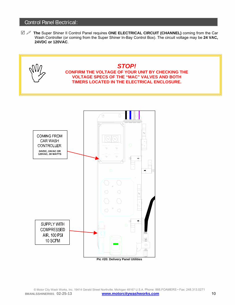
Control Panel Electrical: The Super Shiner II Control Panel requires ONE ELECTRICAL CIRCUIT (CHANNEL) coming from the Car
Wash Controller (or coming from the Super Shiner In-Bay Control Box). The circuit voltage may be 24 VAC, 24VDC or 120VAC.
Pic #20: Delivery Panel Utilities
STOP! CONFIRM THE VOLTAGE OF YOUR UNIT BY CHECKING THE
VOLTAGE SPECS OF THE “MAC” VALVES AND BOTH TIMERS LOCATED IN THE ELECTRICAL ENCLOSURE.
24VDC, 24VAC OR 120VAC, 30 WATTS

© Motor City Wash Works, Inc. 19414 Gerald Street Northville, Michigan 48167 U.S.A. Phone: 866.FOAMERS ▪ Fax: 248.313.0271 8MANLSSHINER001 02-25-13 www.motorcitywashworks.com 11
Connect ONE OUTPUT FUNCTION from the car wash controller to the electrical box as is: BLACK (HOT) TERMINAL 1 - 2 WHITE (NEUTRAL) TERMINAL 3 – 6 GREEN (GROUND) LUG CONNECTOR
Pic #20: Electrical Box
Electrical Connections for In-Bay Unit:
107111
100
107111
100
108111
100
104100
113100
114111
100
BLA
CK
BR
OW
N
YELLO
W
BLU
E
TIRE SHINER COMMAND FROM
CARWASH 24 VDC24 VAC
120 VAC
To #1 OR 2
To #3, 4, 5 OR 6
TIRE SHINER CONTROL BOX
POSITION PHOTO-EYES
BLU
E
BR
OW
N
111
111
TIRE SWITCH
PE
PE
PE
PE
WHITE
(N/C
)
Pic #21: In-Bay Electrical Connections
1 2 3 4 5 6 7 8 9 10 11 12
NEUTRAL
HOT
GROUND

© Motor City Wash Works, Inc. 19414 Gerald Street Northville, Michigan 48167 U.S.A. Phone: 866.FOAMERS ▪ Fax: 248.313.0271 8MANLSSHINER001 02-25-13 www.motorcitywashworks.com 12
The Duration Timer in the In-Bay Control Box has been preset for ONE MINUTE (see Picture # 22 and 23 below). This value is the maximum time allowed for a customer to use the Super Shiner before both applicators retract. If a different time is needed, increase or decrease the value by turning the Duration Timer knob to the desired value.
Pic #22: In Control Box Pic #23: Operation Timer
Control Panel Compressed Air Supply:
Pic #24: Control Panel Utilities
Connect the main air supply to the MAIN AIR REGULATOR. The air supply has to be capable of at least: 10 SCFM @ 100 PSI and no more than 150 PSI (See Picture #24).
NOTE: IT IS IMPERATIVE TO SUPPLY THE DELIVERY PANEL WITH
“CLEAN DRY COMPRESSED AIR”. ANY AMOUNT OF MOISTURE, VAPORIZED OIL OR ANY OTHER IMPURITIES WITHIN
THE MAIN AIR SUPPLY MAY AFFECT THE PERFORMANCE OF THE EQUIPMENT AND LEAD TO PREMATURE WEAR OR MAJOR DAMAGE TO THE DELIVERY UNIT OR
ITS COMPONENTS.
24VDC, 24VAC OR 120VAC, 30 WATTS
OPERATION TIME IS PRESET
AT 1 MINUTE. ROTATE KNOB
TO CHANGE

© Motor City Wash Works, Inc. 19414 Gerald Street Northville, Michigan 48167 U.S.A. Phone: 866.FOAMERS ▪ Fax: 248.313.0271 8MANLSSHINER001 02-25-13 www.motorcitywashworks.com 13
Super Shiner Fundamentals:
Your Super Shiner Applicators and Pumping Station have been designed for years of operation and trouble-free service. The unique GUIDE-RAIL/APPLICATOR brush design allows for the application only when called upon: no more half application on non-selected vehicle tires! The SUPER SHINER II uses two pumps for the chemical delivery: The first pump is a Flo-Jet pump positioned in the back room on the Shiner control panel. This pump delivers chemical to the volumetric pumps located in the tunnel on the applicator stand. There is a volumetric pump for each applicator. The volumetric pump operates like a syringe. The chemical is sucked up into the pump and then is pushed out onto the applicators. A ready signal from one carwash controller function is required to operate any of the functions. There is no power to the panel until this signal is present. Once this signal is present the unit will complete one cycle and extend the applicator brushes until the signal is removed. A complete cycle is as follows:
1. After a ready signal received, the 1st timer starts counting, energizing the air valve to the volumetric pump. 2. After the first timer times out, energizing the 2nd timer and then energizing the air valve operating the N/C
two way valve on the volumetric pump assembly in the tunnel allowing the chemical to squirt onto the cloth brushes.
3. After the 2nd timer times out, the brushes flip out and extend, ready to apply chemical to the tire. The Flojet® pump is now energized to replenish the volumetric pump.
4. When the ready signal is then removed from the system, the air valves turned OFF, the brushes retract to its original position and the NO two way “Dump” valve is now open, releasing the pressure in the feed line.
Initial Soaking of your Super Shiner Brushes:
Remove the BRUSH SECTIONS from one side applicator and lined them in the supplied MIXING TUB. Filled the bottom of the tub with MCWW SUPERSHINER TIRE DRESSING CHEMICAL. Ensure that all pads material is soaked in the chemical. Let it sit in the tub for one to two hours. Remove the pads from the tub and reinstall on the applicator. Repeat with the other side applicator.
Pic #24B: Soaking Tub

© Motor City Wash Works, Inc. 19414 Gerald Street Northville, Michigan 48167 U.S.A. Phone: 866.FOAMERS ▪ Fax: 248.313.0271 8MANLSSHINER001 02-25-13 www.motorcitywashworks.com 14
Manual Operation: There are three buttons on the SUPER SHINER II control box (see Picture #25)
PRIME
P US H-N HOLD
SQUIRTP UMP A DJUST
NORMAL
SIGNAL ON
S QUIRT
P USH-N RE LEASE
OUTPUT
V OLUMETRIC PUMPTIME
S QUIRT VALVETIME
8DCALPNLSNR0005
Pic #25: Electrical Control Box
In order to initially prime the system, remove the covers from both applicators, set the FLOJET PUMP air pressure at 70PSI and all other pressure like shown on Picture #26 and then turn the READY SIGNAL ON and wait for the brushes to extend.
DriverSide
Extend
Volumetric Pump
Pressure
8DCALPNLSNR0001 REV 2
Manufactured in the U.S.A.
www.motorcitywashworks.com
866.362.6377
FlojetPump
Pressure
PassengerSide
Extend
70PSI 25PSI
35PSI40PSI
Pic #26: Air panel
Drop the PUMP SUCTION LINE and the DUMP VALVE RETURN LINE in the chemical drum. Go to the
PASSENGER SIDE VOLUMETRIC PUMP ASSEMBLY and shut the ball valve like shown on Picture #27A below. Now press and hold the PRIME BUTTON (see Picture #25) and have someone monitors the DRIVER SIDE applicator until a SOLID COLUMN OF FLUID IS SEEN IN EACH 1/2” LINES feeding each manifold and is coming out of each applicators nozzle. Shut the DRIVER SIDE BALL VALVE and open the passenger’s side. Repeat the same process by pressing and holding the PRIME BUTTON until fluid is coming out of the applicator nozzles. When done, open the driver side ball valve and set the FLOJET AIR PRESSURE BACK TO 40PSI.
VOLUMETRIC PUMP TIMERS
TWO WAY VALVE (SQUIRT) TIMER
SELECTOR SWITCH
READY SIGNAL LIGHT “ON”
“SQUIRT” PUSH BUTTON
NORMAL POSITION
PUMP ADJUST POSITION
SQUIRT POSITION
PRIME PUSH BUTTON
70PSI 70PS

© Motor City Wash Works, Inc. 19414 Gerald Street Northville, Michigan 48167 U.S.A. Phone: 866.FOAMERS ▪ Fax: 248.313.0271 8MANLSSHINER001 02-25-13 www.motorcitywashworks.com 15
Pic #27B: Control Panel
Turn the SELECTOR from NORMAL to ADJUST, and adjust the rod on the volumetric pump for the desire qty pumped at the brushes. 1" of the rod equal about one once.
Turn the SELECTOR from ADJUST to SQUIRT position and press and PRESS AND RELEASE the
SQUIRT BUTTON. Observe the fluid being “squirt” out of the nozzles and onto the back of the brushes. Repeat until each nozzle squirt properly.
Pic #28: Pump Adjustment
1” = 1 ONCE
ELECTRICAL BOX
VOLUMETRIC PUMP VALVE
DUMP VALVE
DUMP VALVE RETURN LINE
AIR PANEL
FLOJET PUMP
PUMP SUCTION LINE
MAIN AIR FILTER/REGULATOR
MAIN AIR VALVE
EXTEND AND ROTATE VALVE
FLOJET PUMP VALVE
“SQUIRT” VALVE
Pic #27A: Ball Valve
SHUT THE ISOLATION BALL VALVE

© Motor City Wash Works, Inc. 19414 Gerald Street Northville, Michigan 48167 U.S.A. Phone: 866.FOAMERS ▪ Fax: 248.313.0271 8MANLSSHINER001 02-25-13 www.motorcitywashworks.com 16
Finally, turn OFF the Ready signal and test again by turning ON the READY signal and observe the Applicators operation: The volumetric pumps will inject chemical into the brushes and then the applicators will EXTEND and the brushes will ROTATE OUT (“FLIP OUT”). Adjust each flow control fitting located at each extend cylinder for proper operation: For a quicker operation, OPEN the FLOW CONTROL. For a slower operation, CLOSE the FLOW CONTROL.
Program the Car wash Controller Output to turn ON your Super Shiner II at the beginning of the front tire
for each vehicle. Test with a vehicle and adjust the brush pressure against the tire by INCREASING or DECREASING the air pressure of the DRIVER’S SIDE or PASSENGER’S SIDE AIR REGULATOR.
Driver Side Positive Stop Installation:
After start up, verify the positive stop adjustment on the applicator when fully retracted. Make sure the exit end of the applicator is FLUSH WITH THE INSIDE EDGE OF THE OUTSIDE GUIDE RAIL (see Pic #29). Adjust the positive stop (mounted on the applicator) as needed.
Pic #29: Guide Rail
Locate the FLOOR MOUNTED POSITIVE STOP and position it behind the main beam on the exit end of the driver side applicator (see Pic 30 below).
Pic #30: Floor Mounted Positive Stop
Secure the floor mounted positive stop to the floor using wedge anchor bolts (see Picture #31). You may insert shims behind the bumper stop for adjustment or relocate the bumper stop like shown on Picture #34 for height adjustment.
FLUSH
POSITIVE STOP
FLUSH
FLOOR MOUNTED POSITIVE STOP

© Motor City Wash Works, Inc. 19414 Gerald Street Northville, Michigan 48167 U.S.A. Phone: 866.FOAMERS ▪ Fax: 248.313.0271 8MANLSSHINER001 02-25-13 www.motorcitywashworks.com 17
STOP ADJUSTMENT
HEIGHTADJUSTMENT
Pic #31: Anchors Pic #32: Shims Pic #33: Bumper Stop Pic #34: Height Adjustment
Daily Maintenance Procedures:
Inspect DAILY each applicator and Delivery Panel for proper operation. Check the MAIN AIR FILTER/REGULATOR for presence of water.
Inspect DAILY each brush for wear and/or visible damages. Replace damaged brush section. To replace any brush section, follow the procedures below:
Step 1: Push the override button for the EXTEND valve and then shut the main air supply and drain the air from the system.
Step 2: Remove the plastic guide rail from the exit end of the applicator. Step 3: Remove the end cap. Step 4: Remove the grease fitting. Step 5: Slide out the brush section and replace the used section. Step 6: Reinstall the grease fitting, the end cap and the guide rail. Open the air
supply and release the extend valve override button.
Exit Guide Rail End Cap
Grease Fitting Brush Section
2
5
4
3

© Motor City Wash Works, Inc. 19414 Gerald Street Northville, Michigan 48167 U.S.A. Phone: 866.FOAMERS ▪ Fax: 248.313.0271 8MANLSSHINER001 02-25-13 www.motorcitywashworks.com 18
Inspect DAILY each applicator and Delivery Panel for proper operation. Check the MAIN AIR FILTER for presence of water.
Monthly Maintenance Procedures:
Clean Delivery Station MAIN AIR FILTER ONCE A MONTH. Grease all applicator bearings ONCE A MONTH. See below for greasing points.
Entrance End Brush Bearing (1 Fitting) Exit Brush End Bearing (1 fitting)
Applicator Arm Bearings (8 Fittings)

© Motor City Wash Works, Inc. 19414 Gerald Street Northville, Michigan 48167 U.S.A. Phone: 866.FOAMERS ▪ Fax: 248.313.0271 8MANLSSHINER001 02-25-13 www.motorcitywashworks.com 19
Pneumatic Schematic:

© Motor City Wash Works, Inc. 19414 Gerald Street Northville, Michigan 48167 U.S.A. Phone: 866.FOAMERS ▪ Fax: 248.313.0271 8MANLSSHINER001 02-25-13 www.motorcitywashworks.com 20
Air Lines Schematic:
CH
EM
ICA
L-12 "
BR
AID
ED H
OSE
FR
OM
BA
CKR
OO
M
PA
NE
L-TE
E'D O
FF IN
TUN
NEL
38 " GR
AY
AIR
LINE
38 " OR
AN
GE
AIR
LINE
38 " PU
RPLE
AIR
LINE
DR
IVE
R S
IDE
V
OLU
ME
TR
IC
PU
MP
PA
SS
- SID
E
VO
LUM
ET
RIC
P
UM
P
38 " BLA
CK
AIR
LINE
38 " BLU
EA
IRLIN
E
38 " RED
AIR
LINE
DR
IVE
R S
IDE
C
YLIN
DE
RP
AS
S - S
IDE
C
YLIN
DE
RD
RIVE
R
SID
E
RO
TAR
Y A
CTU
ATOR
PA
SS
SID
E R
OT
ARY
AC
TUATO
R38 " B
LACK
AIR
LINE
38 " YE
LLOW
AIR
LINE
CH
EM
ICAL
SU
PPLY
TO
MA
IN BEAM
CH
EM
ICAL
SU
PPLY
TO
MA
IN BEAM
CH
EM
ICA
L -
12 " BR
AID
ED
HO
SE
-NO
TE: TH
IS H
OS
E M
US
T BE
RO
UTED
FR
OM
OV
ERH
EA
D
TO
FE
ED
THE
VO
LU
MET
RIC
P
UM
PS
DU
MP
VA
LVE
-GO
ES
BA
CK
TO C
HE
MIC
AL
DR
UM
BA
CK
RO
OM
C
ON
TR
OL
PA
NE
L

© Motor City Wash Works, Inc. 19414 Gerald Street Northville, Michigan 48167 U.S.A. Phone: 866.FOAMERS ▪ Fax: 248.313.0271 8MANLSSHINER001 02-25-13 www.motorcitywashworks.com 21
In-Bay Control Box Electrical Schematic:
REA
DY
SIG
NA
L:"O
N" LIG
HT. TH
IS LIGH
T IS O
N
ON
LY W
HE
N TH
E SU
PERSH
INER
H
AS P
OW
ER
NO
RM
AL:
THIS
PO
SITIO
N IS FO
R N
OR
MAL
OP
ER
ATIN
G
PU
MP
AD
JUST:
WH
EN
IN TH
IS P
OS
ITION
YOU
CAN
ADJU
ST TH
E V
OLU
ME
TRIC
PU
MP VO
LUM
ES FOR
D
RIV
ER
OR
PA
SS
EN
GE
R SID
E (SEE MAN
UAL
FOR
AD
JUS
TME
NT PR
OC
EDU
RES)
NO
TE: 1" O
F VO
LUM
ETRIC
PUM
P A
DJU
STM
EN
T IS A
PP
RO
XIM
ATELY 1 OU
NC
E O
F CH
EMIC
AL
SQ
UIR
T:W
HE
N IN
THIS
PO
SITIO
N YO
U C
AN C
YCLE
THE
PU
MP
SE
QU
EN
CE FO
R O
NE
AP
PLIC
ATIO
N A
T A TIME.
BY
PR
ES
SIN
G TH
E B
UTTO
N, YO
U C
AN VIEW
TH
E N
OZZLE
SQU
IRTIN
G
NO
TES:TH
E R
EA
DY
SIG
NA
L HA
S TO
BE ON
AND
THE
CO
VE
RS
HA
VE
TO B
E R
EMO
VED BEFO
RE
PR
EE
S TH
E S
QU
IRT BU
TTON
PR
IME:
THIS
FUN
CTIO
N A
LLOW
S YOU
TO PR
IME
THE
CH
EM
ICA
L LINES FR
OM
THE
FLOJET
PU
MP
TO TH
E N
OZZLES.
NO
TES:TH
E R
EA
DY
SIG
NA
L HAS TO
BE ON
TO
HA
VE
THIS
FUN
CTIO
N W
OR
KING
TIMER
#1:TH
IS TIM
ER
OP
ER
ATE
S THE TIM
E V
OLU
ME
TRIC
PU
MP W
ILL BE ON
TIM
ER
SE
T: 1 SECO
ND
A R
EA
DY
SIG
NA
L (A M
AIN
TAIN
ED
SIG
NA
L) FRO
M TH
E C
AR
WA
SH
CO
NTR
OLLER
IS REQ
UIR
ED TO
OPER
ATE A
NY O
F THE FU
NC
TION
S. TH
ER
E IS
NO
PO
WE
R TO
THE
PA
NE
L UN
TIL THIS
SIG
NA
L IS P
RE
SE
NT. O
NC
E TH
IS S
IGN
AL IS PR
ESENT TH
E UN
IT WILL C
YCLE O
NE C
OM
PLETE CYC
LE AN
D
EX
TEN
D TH
E A
PP
LICA
TOR
BR
US
HE
S U
NTIL TH
E S
IGN
AL IS
RE
MO
VE
D. TO
OP
ER
ATE TH
E FUN
CTIO
NS B
ELOW
LEAVETH
E REA
DY SIG
NA
L"ON
".A
CO
MP
LETE
CY
CLE
IS A
S FOLLO
WS :
AFTE
R A
RE
AD
Y S
IGN
AL IS
RE
CIE
VE
D, TH
E 1S
T TIME
R S
TAR
TS C
OU
NTIN
G, E
NE
RG
IZING
THE VO
LUM
ETRIC
PUM
P. AFTER
THE 1ST TIM
ER
TIME
S O
UT, TH
E S
EC
ON
D TIM
ER
TUR
NS
ON
, OP
EN
ING
THE
2-WA
Y V
ALV
E LO
CA
TED
ON
THE O
UTLET O
F THE VO
LUM
ETRIC
PUM
P ASSEM
BLY IN
THE
TUN
NE
L ALLO
WIN
G TH
E C
HE
MIC
AL TO
SQ
UIR
T ON
TO TH
E C
LOTH
BR
US
HE
S A
FTER
THE
2ND
TIMER
TIMES O
UT, TH
E APPLIC
ATO
R B
RU
SHES FLIPS O
UT
AN
D E
XTE
ND
S TO
THE
TIRE
. THE
FLOJE
T PU
MP
IS A
LSO
EN
RG
IZED TO
FEED TH
E VOLU
METR
IC PU
MP.
TIMER
#2:TH
IS TIM
ER
OP
ER
ATES TH
E TWO
W
AY
VA
LVE
, LOC
ATED
AT THE
OU
TLET O
F THE
VO
LUM
ETRIC
PUM
P TIM
ER
SE
T: 1 SECO
ND

© Motor City Wash Works, Inc. 19414 Gerald Street Northville, Michigan 48167 U.S.A. Phone: 866.FOAMERS ▪ Fax: 248.313.0271 8MANLSSHINER001 02-25-13 www.motorcitywashworks.com 22
VLV2
2W NORMALLY OPENDUMP VALVE
T1
VOLUMETRICPUMPS "ON" TIME
L1NEUTRAL
T12 SEC
VLV3
3W VALVE TOSQUIRT VALVES
T2-12 SEC
T2
APPLICATIONVALVES "ON" TIME
VLV5
4W VALVE TOVOLUMETRIC PUMPS
T2-22 SEC
VLV6
4W VALVE TOEXTEND AND FLIP OUT
VLV4
3W VALVE TOFLOWJET PUMP
VLV1
3W VALVE NORMALLYOPEN FOR MAIN AIR
PRIME
S3
ADJUST-SQUIRT3 POS
SWITCH
S2
SQUIRT
S1
ADJUST (CENTER POS)
SQUIRT (RIGHT POS)
ADJUST (CENTER POS)
SQUIRT (RIGHT POS)
LIT1
SQUIRT (RIGHT POS)
POWER
A
B
C
D
E
FIELD SUPPLIEDREADY SIGNAL
TNL#3
100 N
N
TNL#4
TNL#4
100
100
100
100
100
100
100
100
100
100
101
101
100
102
103
104
105
105
105
105
N
N
N
N
N
N
N
N
104
104
104
106
106
106
100
100
107
104
TNL#5
TNL#5
TNL#4
TNL#6
TNL#6
TNL#3
TNL#2
TNL#2
TNL#1
TNL#2
TNL#9
TNL#10
TNL#11
TNL#7
TNL#8
TNL#12
SKT#8
SKT#6
SKT#1
SKT#4
SKT#3
SKT#8
SKT#6
SKT#5

© Motor City Wash Works, Inc. 19414 Gerald Street Northville, Michigan 48167 U.S.A. Phone: 866.FOAMERS ▪ Fax: 248.313.0271 8MANLSSHINER001 02-25-13 www.motorcitywashworks.com 23
In-Bay Control Box Electrical Schematic:
Lin
e 11
5VA
C
Ne
utr
al
101
102
102
107
103
TR1
CR1
104 111
111
OSR1
Photo Eye
Tire Switch
Tire Shiner
OSR1
113 114
120 VACGFCI
111100
TR1
TR1
108
CR1
T.O.104
111104
107 107 108
CB1
101
101
Warranty and Return Procedure: Motor City Wash Works warrants this product to be free of defect in material and/or workmanship for a period of one year. During the warranty period MCWW will at its discretion, at no charge to the customer, repair or replace this product if found defective, with a new or refurbished unit, not to include costs of removal or installation. Any product returned to MCWW for warranty has to have a Return Material Authorization Number. All shipping costs to MCWW are assumed by the customer. This is only a summary of MCWW’s Limited Warranty. Please, communicate with MCWW for our complete warranty. Prior to returning any product to MCWW, the customer must call in for a Return Material Authorization Number and a copy of our Return Material Authorization Form must be completed. The RMA number must be written clearly on the outside of the shipping package and a copy of the form must be included in the package.

© Motor City Wash Works, Inc. 19414 Gerald Street Northville, Michigan 48167 U.S.A. Phone: 866.FOAMERS ▪ Fax: 248.313.0271 8MANLSSHINER001 02-25-13 www.motorcitywashworks.com 24
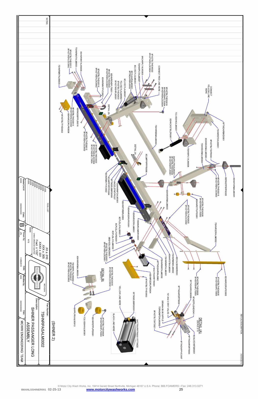
Support Documents
© Motor City Wash Works, Inc. 19414 Gerald Street Northville, Michigan 48167 U.S.A. Phone: 866.FOAMERS ▪ Fax: 248.313.0271 8MANLSSHINER001 02-25-13 www.motorcitywashworks.com 25

© Motor City Wash Works, Inc. 19414 Gerald Street Northville, Michigan 48167 U.S.A. Phone: 866.FOAMERS ▪ Fax: 248.313.0271 8MANLSSHINER001 02-25-13 www.motorcitywashworks.com 26

© Motor City Wash Works, Inc. 19414 Gerald Street Northville, Michigan 48167 U.S.A. Phone: 866.FOAMERS ▪ Fax: 248.313.0271 8MANLSSHINER001 02-25-13 www.motorcitywashworks.com 27

© Motor City Wash Works, Inc. 19414 Gerald Street Northville, Michigan 48167 U.S.A. Phone: 866.FOAMERS ▪ Fax: 248.313.0271 8MANLSSHINER001 02-25-13 www.motorcitywashworks.com 28
Related Documents