Super-Scalar Processor Design William M. Johnson Technical Report No. CSL-TR-89-383 June 1989 Computer Systems Laboratory Departments of Electrical Engineering and Computer Science Stanford University Stanford, CA 943054055 Abstract A super-scalar processor is one that is capable of sustaining an instruction-execution rate of more than one instruction per clock cycle. Maintaining this execution rate is primarily a problem of scheduling processor resources (such as functional units) for high utilrzation. A number of scheduling algorithms have been published, with wide-ranging claims of performance over the single-instruction issue of a scalar processor. However, a number of these claims are based on idealizations or on special-purpose applications. This study uses trace-driven simulation to evaluate many different super-scalar hardware organizations. Super-scalar performance is limited caused by both branch delays and instruction mis ap rimarily b instruction-fetch inefficiencies rgnment. 8 ecause of this instruction-fetch lirnitation, it is not worthwhile to explore highly-concurrent execution hardware, Rather, it is more appro riate to explore economical execution hardware that more closely matches the instructron tLoughput provided b reducing the instruction-fetch inef ii the instruction fetcher. This stud ciencies and explores the resulting iI examines techniques for ardware organizatrons. This study concludes that a super-scalar processor can have nearly twice the scalar processor, but that this re uires 1 that four major hardware features: p” xformance of a out-o -order execution, register renarmng, branch pre iction, and a four-instruction decoder. These features are interdependent, and removing any single feature reduces average performance by 18% or more. However, there are many hardware simplifications that cause only a small performance reduction. Key Words and Phrases: super-scalar, instruction-level concurrency, instruction-level parallelism, fine-grained parallelism, instruction scheduling, hardware scheduling, register renaming, branch prediction.

Welcome message from author
This document is posted to help you gain knowledge. Please leave a comment to let me know what you think about it! Share it to your friends and learn new things together.
Transcript
Super-Scalar Processor Design
William M. Johnson
Technical Report No. CSL-TR-89-383
June 1989
Computer Systems LaboratoryDepartments of Electrical Engineering and Computer Science
Stanford UniversityStanford, CA 943054055
Abstract
A super-scalar processor is one that is capable of sustaining an instruction-execution rate of morethan one instruction per clock cycle. Maintaining this execution rate is primarily a problem ofscheduling processor resources (such as functional units) for high utilrzation. A number ofscheduling algorithms have been published, with wide-ranging claims of performance over thesingle-instruction issue of a scalar processor. However, a number of these claims are based onidealizations or on special-purpose applications.This study uses trace-driven simulation to evaluate many different super-scalar hardwareorganizations. Super-scalar performance is limitedcaused by both branch delays and instruction misap
rimarily b instruction-fetch inefficienciesrgnment. 8ecause of this instruction-fetch
lirnitation, it is not worthwhile to explore highly-concurrent execution hardware, Rather, it ismore appro riate to explore economical execution hardware that more closely matches theinstructron tLoughput provided breducing the instruction-fetch inefii
the instruction fetcher. This studciencies and explores the resulting iI
examines techniques forardware organizatrons.
This study concludes that a super-scalar processor can have nearly twice thescalar processor, but that this re uires
1that four major hardware features: p”
xformance of aout-o -order execution,
register renarmng, branch pre iction, and a four-instruction decoder. These features areinterdependent, and removing any single feature reduces average performance by 18% or more.However, there are many hardware simplifications that cause only a small performancereduction.
Key Words and Phrases: super-scalar, instruction-level concurrency, instruction-levelparallelism, fine-grained parallelism, instruction scheduling, hardware scheduling, registerrenaming, branch prediction.

Copyright 01989
by
William M. Johnson
Table of Contents
Chapter 1 Introduction . . . . . . . . . . . . . . . . . . . . . . . . . . . . . . . . 1
Chapter 2 Background . . . . . . . . . . . . . . . . . . . . . . . . . . . . . . . . 52.1 Fundamental Concepts . . . . . . . . . . . . . . . . . . . . . . . . . . . . . . . . . . . . . . . . . 5
2.1.1 Instruction Scheduling Policies . . . . . . . . . . . . . . . . . . . . . . . . . . . . . . 52.1.2 Scheduling Constraints . . . . . . . . . . . . . . . . . . . . . . . . . . . . . . . . . . . . . 82.1.3 Storage Conflicts and Register Renaming . . . . . . . . . . . . . . . . . . . . . . 10
2.2 Published Techniques for Single-Instruction Issue . . . . . . . . . . . . . . . . . . . . 112.2.1 Common Data Bus-Tomasulo’s Algorithm . . . . . . . . . . . . . . . . . . . . 122.2.2 Derivatives of Tomasulo’s Algorithm . . . . . . . . . . . . . . . . . . . . . . . . . 13
2.3 Published Techniques for Multiple-Insauction Issue . . . . . . . . . . . . . . . . . . 152.3.1 Detecting Independent Instructions with a Pm-Decode Stack . . . . . . . 152.3.2 Ordering Matrices . . . . . . . . . . . . . . . . . . . . . . . . . . . . . . . . . . . . . . . . . 162.3.3 Concurrency Detection in Directly-Executed Languages . . . . . . . . . . 172.3.4 Dispatch Stack . . . . . . . . . . . . . . . . . . . . . . . . . . . . . . . . . . . . . . . . . . . 182.3.5 High Performance Substrate . . . . . . . . . . . . . . . . . . . . . . . . . . . . . . . . . 192.3.6 Multiple-Instruction Issue with the CRAY-1 Architecture . . . . . . . . . 20
2.4 Observations and Conclusions . . . . . . . . . . . . . . . . . . . . . . . . . . . . . . . . . . . . 20
Chapter 3 Methodology and Potential Performance . . . . . . . . . . . 223.1 Simulation Technique . . . . . . . . . . . . . . . . . . . . . . . . . . . . . . . . . . . . . . . . . . 223.2 BenchmarkPrograms . . . . . . . . . . . . . . . . . . . . . . . . . . . . . . . . . . . . . . . . . . 243.3 Initial Processor Model . . . . . . . . . . . . . . . . . . . . . . . . . . . . . . . . . . . . . . . . . 26
3.3.1 Basic Organization . . . . . . . . . . . . . . . . . . . . . . . . . . . . . . . . . . . . . . . . 263.3.2 Implementation Description . . . . . . . . . . . . . . . . . . . . . . . . . . . . . . . . . 283.3.3 Processor Configuration . . . . . . . . . . . . . . . . . . . . . . . . . . . . . . . . . . . . 3 1
3.4 Results Using an Ideal Instruction Fetcher . . . . . . . . . . . . . . . . . . . . . . . . . . 33
Chapter 4 Instruction Fetching and Decoding . . . . . . . . . . . . . . . 354.1 Branches and Instruction-Fetch Inefficiencies . . . . . . . . . . . . . . . . . . . . . . . 354.2 Improving Fetch Efficiency . . . . . . . . . . . . . . . . . . . . . . . . . . . . . . . . . . . . . . 38
4.2.1 Scheduling Delayed Branches . . . . . . . . . . . . . . . . . . . . . . . . . . . . . . . 384.2.2 Branch Prediction . . . . . . . . . . . . . . . . . . . . . . . . . . . . . . . . . . . . . . . . . 404.2.3 Aligning and Merging . . . . . . . . . . . . . . . . . . . . . . . . . . . . . . . . . . . . . 414.2.4 Simulation Results and Observations . . . . . . . . . . . . . . . . . . . . . . . . . . 43
4.3 Implementing Hardware Branch Prediction . . . . . . . . . . . . . . . . . . . . . . . . . 464.3.1 Basic Organization . . . . . . . . . . . . . . . . . . . . . . . . . . . . . . . . . . . . . . . . 474.3.2 Setting and Interpreting Cache Entries . . . . . . . . . . . . . . . . . . . . . . . . . 484.3.3 Predicting Branches . . . . . . . . . . . . . . . . . . . . . . . . . . . . . . . . . . . . . . . 494.3.4 Hardware and Performance Costs . . . . . . . . . . . . . . . . . . . . . . . . . . . . 50
4.4 Implementing a Four-Instruction Decoder . . . . . . . . . . . . . . . . . . . . . . . . . . 52
i i i

4.4.1 Implementing a Hardware Register-Port Arbiter . . . . . . . . . . . . . . . . .4.4.2 Limiting Register Access Via Instruction Format . . . . . . . . . . . . . . . .
4.5 Implementing Branches . . . . . . . . . . . . . . . . . . . . . . . . . . . . . . . . . . . . . . . . .4.5.1 Number of Pending Branches . . . . . . . . . . . . . . . . . . . . . . . . . . . . . . . .4.5.2 Order of Branch Execution . . . . . . . . . . . . . . . . . . . . . . . . . . . . . . . . . .4.5.3 Simplifying Branch Decoding . . . . . . . . . . . . . . . . . . . . . . . . . . . . . . .
4.6 Observations and Conclusions . . . . . . . . . . . . . . . . . . . . . . . . . . . . . . . . . . .
Chapter 5 Operand Management . . . . . . . . . . . . . . . . . . . . . . . .5.1 Buffering State Information for Restart . . . . . . . . . . . . . . . . . . . . . . . . . . . .
5.1.1 Sequential, Look-Ahead, and Architectural State . . . . . . . . . . . . . . . .5.1.2 Checkpoint Repair . . . . . . . . . . . . . . . . . . . . . . . . . . . . . . . . . . . . . . . .5.1.3 History Buffer . . . . . . . . . . . . . . . . . . . . . . . . . . . . . . . . . . . . . . . . . . . .5.1.4 Reorder Buffer . . . . . . . . . . . . . . . . . . . . . . . . . . . . . . . . . . . . . . . . . . .5.1.5 Future File . . . . . . . . . . . . . . . . . . . . . . . . . . . . . . . . . . . . . . . . . . . . . .
5.2 Restart Implementation and Effects on Performance . . . . . . . . . . . . . . . . . .5.2.1 Mispredicted Branches . . . . . . . . . . . . . . . . . . . . . . . . . . . . . . . . . . . . .5.2.2 Exceptions . . . . . . . . . . . . . . . . . . . . . . . . . . . . . . . . . . . . . . . . . . . . . .5.2.3 Effect of Restart Hardware on Performance . . . . . . . . . . . . . . . . . . . .
5.3 DependencyMechanisms . . . . . . . . . . . . . . . . . . . . . . . . . . . . . . . . . . . . . . .5.3.1 Value of Register Renaming . . . . . . . . . . . . . . . . . . . . . . . . . . . . . . . .5.3.2 Register Renaming with a Reorder Buffer . . . . . . . . . . . . . . . . . . . . . .5.3.3 Renaming with a Future File: Tomasulo’s Algorithm . . . . . . . . . . . . .5.3.4 Other Mechanisms to Resolve Anti-Dependencies . . . . . . . . . . . . . . .5.3.5 Other Mechanisms to Resolve Output Dependencies . . . . . . . . . . . . .5.3.6 PartialRenaming . . . . . . . . . . . . . . . . . . . . . . . . . . . . . . . . . . . . . . . . .
5.4 Result Buses and Arbitration . . . . . . . . . . . . . . . . . . . . . . . . . . . . . . . . . . . . .5.5 ResultForwarding . . . . . . . . . . . . . . . . . . . . . . . . . . . . . . . . . . . . . . . . . . . . .5.6 Implementing Renaming with a Reorder Buffer . . . . . . . . . . . . . . . . . . . . . .
5.6.1 Allocating Processor Resources . . . . . . . . . . . . . . . . . . . . . . . . . . . . . .5.6.2 InstructionDecode . . . . . . . . . . . . . . . . . . . . . . . . . . . . . . . . . . . . . . . .5.6.3 Instruction Completion . . . . . . . . . . . . . . . . . . . . . . . . . . . . . . . . . . . . .
5.7 Observations and Conclusions . . . . . . . . . . . . . . . . . . . . . . . . . . . . . . . . . . .
Chapter 6 Instruction Scheduling and Issuing . . . . . . . . . . . . . . .6.1 Reservation Stations . . . . . . . . . . . . . . . . . . . . . . . . . . . . . . . . . . . . . . . . . . .
6.1.1 Reservation Station Operation . . . . . . . . . . . . . . . . . . . . . . . . . . . . . . .6.1.2 Performance Effects of Reservation-Station Size . . . . . . . . . . . . . . . .
6.2 Central Instruction Window . . . . . . . . . . . . . . . . . . . . . . . . . . . . . . . . . . . . .6.2.1 The Dispatch Stack . . . . . . . . . . . . . . . . . . . . . . . . . . . . . . . . . . . . . . . .6.2.2 The Register Update Unit . . . . . . . . . . . . . . . . . . . . . . . . . . . . . . . . . . .6.2.3 Using the Reorder Buffer to Simplify the Central Window . . . . . . . . .6.2.4 Operand Buses . . . . . . . . . . . . . . . . . . . . . . . . . . . . . . . . . . . . . . . . . . .6.2.5 Central Window Implementation . . . . . . . . . . . . . . . . . . . . . . . . . . . . .
i v
54565859 .596062
64646566676869717174757777787979808284858888909293
95979798
100101103105108110

1
6.3 Loads andstores . . . . . . . . . . . . . . . . . . . . . . . . . . . . . . . . . . . . . . . . . . . . . . 1116.3.1 TotalOrderingofLoadsandStores . . . . . . . . . . . . . . . . . . . . . . . . . . . 1136.3.2 Load Bypassing of Stores . . . . . . . . . . . . . . . . . . . . . . . . . . . . . . . . . . . 1136.3.3 Load Bypassing with Forwarding . . . . . . . . . . . . . . . . . . . . . . . . . . . . 1156.3.4 Simulation Results . . . . . . . . . . . . . . . . . . . . . . . . . . . . . . . . . . . . . . . . 1156.3.5 Implementing Loads and Stores with a Central Instruction Window . 1166.3.6 Effects of Store Buffer Size . . . . . . . . . . . . . . . . . . . . . . . . . . . . . . . . . 1196.3.7 Memory Dependency Checking . . . . . . . . . . . . . . . . . . . . . . . . . . . . . . 119
6.4 Observations and Conclusions . . . . . . . . . . . . . . . . . . . . . . . . . . . . . . . . . . . 121
Chapter 7 Conclusion . . . . . . . . . . . . . . . . . . . . . . . . . . . . . . . . . 1237.1 Major Hardware Features . . . . . . . . . . . . . . . . . . . . . . . . . . . . . . . . . . . . . . . 1237.2 Hardware Simplifications . . . . . . . . . . . . . . . . . . . . . . . . . . . . . . . . . . . . . . . 1257.3 Future Directions . . . . . . . . . . . . . . . . . . . . . . . . . . . . . . . . . . . . . . . . . . . . . . 127
References . . . . . . . . . . . . . . . . . . . . . . . . . . . . . . . . . . . . . . . . . . . 129
V


List of Tables
Table 1. Benchmark Program Descriptions . . . . . . . . . . . . . . . . . . . . . . . . . . . . . . . 25Table 2. Comparisons of Scalar and Super-Scalar Pipelines . . . . . . . . . . . . . . . . . . 31Table 3. Configuration of Functional Units . . . . . . . . . . . . . . . . . . . . . . . . . . . . . . . 32Table 4. Estimate of Register-Port Arbiter Size: Two Logic Levels . . . . . . . . . . . . 55Table 5. Critical Path for Central-Window Scheduling . . . . . . . . . . . . . . . . . . . . . . 111Table 6. Performance Advantage of Major Processor Features . . . . . . . . . . . . . . . 124Table 7. Cumulative Effects of Hardware Simplifications . . . . . . . . . . . . . . . . . . . 125
v i i


Figure 1.Figure 1.Figure 2.Figure 3.
Figure 4.Figure 5.Figure 6.Figure 7.Figure 8.
Figure 9.
Figure 10.Figure 11.
Figure 12.Figure 13.Figure 14.
Figure 15.
Figure 16.Figure 17.
Figure 18.
Figure 19.
List of Figures
Simple Definition of Super-Scalar Processor . . . . . . . . . . . . . . . . . . . . . . 2Simple Definition of Super-Scalar Processor . . . . . . . . . . . . . . . . . . . . . . 2Super-Scalar Pipeline with In-Order Issue and Completion . . . . . . . . . . 6Super-Scalar Pipeline with In-Order Issue andOut-of-Order Completion . . . . . . . . . . . . . . . . . . . . . . . . . . . . . . . . . . . . . 6Super-Scalar Pipeline with Out-of-Order Issue and Completion . . . . . . . 8Flowchart for Trace-Driven Simulation . . . . . . . . . . . . . . . . . . . . . . . . . . 23Sample Instruction-Issue Distribution . . . . . . . . . . . . . . . . . . . . . . . . . . . 27Block Diagram of Processor Model . . . . . . . . . . . . . . . . . . . . . . . . . . . . . 29Potential Speedup of Three Scheduling Policies, usingIdeal Instruction Fetcher . . . . . . . . . . . . . . . . . . . . . . . . . . . . . . . . . . . . . . 33Speedups with Ideal Instruction Fetcher and withInstruction Fetcher Modeled after Scalar Fetcher . . . . . . . . . . . . . . . . . . 34Sequence of Two Instruction Runs for Illustrating Decoder Behavior . . 36Sequence of Instructions in Figure 10 ThroughTwo-Instruction and Four-Instruction Decoders . . . . . . . . . . . . . . . . . . . 36Dynamic Run Length Distribution for Taken Branches . . . . . . . . . . . . . . 37Branch Delay and Penalty Versus Speedup . . . . . . . . . . . . . . . . . . . . . . . 39Sequence of Instructions in Figure 11 ThroughTwo-Instruction and Four-Instruction Decoders withBranchPrediction . . . . . . . . . . . . . . . . . . . . . . . . . . . . . . . . . . . . . . . . . . . 40Sequence of Instructions in Figure 11 withSingle-Cycle Delay for Decoding Branch Prediction . . . . . . . . . . . . . . . 41Fetch Efficiencies for Various Run Lengths . . . . . . . . . . . . . . . . . . . . . . 42Sequence of Instructions in Figure 10 ThroughTwo-Instruction and Four-Instruction Decoders withBranch Prediction and Aligning . . . . . . . . . . . . . . . . . . . . . . . . . . . . . . . . 43Sequence of Instructions in Figure 10 ThroughTwo-Instruction and Four-Instruction Decoders withBranch Prediction, Aligning, and Merging . . . . . . . . . . . . . . . . . . . . . . . 43Speedups of Fetch Alternatives with Two-Instruction Decoder . . . . . . . 44
Figure 20. Speedups of Fetch Alternatives with Four-Instruction Decoder . . . . . . . 44Figure 21. Average Branch Target Buffer Hit Rates . . . . . . . . . . . . . . . . . . . . . . . . . 46Figure 22. Instruction Cache Entry for Branch Prediction . . . . . . . . . . . . . . . . . . . . 48Figure 23. Example Cache Entries for Code Sequence of Figure 14 . . . . . . . . . . . . 49Figure 24. Performance Decrease Caused by Storing All
Branch Predictions with Cache Blocks . . . . . . . . . . . . . . . . . . . . . . . . . . 51Figure 25. Performance Degradation with Single-Port Cache Tags . . . . . . . . . . . . . 52
i x

Figure 26. Register Usage Distribution of a Four-Instruction Decoder-NoBranchDelays . . . . . . . . . . . . . . . . . . . . . . . . . . . . . . . . . . . . . . . . . . . 53
Figure 27. Performance Degradation Caused by Limiting aFour-Instruction Decoder to Four Register-File Ports . . . . . . . . . . . . . . . 54
Figure 28. Format for Four-Instruction Group Limiting theNumber of Registers Accessed . . . . . . . . . . . . . . . . . . . . . . . . . . . . . . . . . 56
Figure 29. Example Operand Encoding using Instruction Format of Figure 28 . . . . 57Figure 30. One Approach to Handling a Branch Target Within
InstructionGroup . . . . . . . . . . . . . . . . . . . . . . . . . . . . . . . . . . . . . . . . . . . 58Figure 31. Reducing the Number of Outstanding Branches . . . . . . . . . . . . . . . . . . . 60Figure 32. Performance Increase by Executing Multiple
Correctly-Predicted Branches Per Cycle . . . . . . . . . . . . . . . . . . . . . . . . . 61Figure 33. Performance Decrease Caused by Computing One
Branch Target Address Per Decode Cycle . . . . . . . . . . . . . . . . . . . . . . . . 62Figure 34. Illustration of Sequential, Look-Ahead, and Architectural State . . . . . . . 65Figure 35. History Buffer Organization . . . . . . . . . . . . . . . . . . . . . . . . . . . . . . . . . . . 68Figure 36. Reorder Buffer Organization . . . . . . . . . . . . . . . . . . . . . . . . . . . . . . . . . . 69Figure 37. Future File Organization . . . . . . . . . . . . . . . . . . . . . . . . . . . . . . . . . . . . . . 70Figure 38. Correcting State After a M.&predicted Branch . . . . . . . . . . . . . . . . . . . . . 72Figure 39. Distribution of Additional Branch Delay Caused by Waiting for a
M.&predicted Branch to Reach the Head of the Reorder Buffer . . . . . . . 73Figure 40. Performance Degradation Caused by Waiting for a
Mispredicted Branch to Reach the Head of the Reorder Buffer . . . . . . . 74Figure 41. Effect of Reorder-Buffer Size on Performance:
Allocating for Every Instruction . . . . . . . . . . . . . . . . . . . . . . . . . . . . . . . . 76Figure 42. Reducing Concurrency by Eliminating Register Renaming . . . . . . . . . . 78Figure 43. Performance Advantage of Eliminating Decoder Stalls for
Output Dependencies . . . . . . . . . . . . . . . . . . . . . . . . . . . . . . . . . . . . . . . . 8 1Figure 44. Performance Advantage of Partial Renaming . . . . . . . . . . . . . . . . . . . . . 83Figure 45. Integer Result-Bus Utilization at High Performance Levels . . . . . . . . . . 84Figure 46. Effect of the Number of Result Buses on Performance . . . . . . . . . . . . . . 85Figure 47. Distribution of Number of Operands Supplied by
Forwarding, Per Result . . . . . . . . . . . . . . . . . . . . . . . . . . . . . . . . . . . . . . . 86Figure 48. Performance of Direct Tag Search for
Various Numbers of List Entries . . . . . . . . . . . . . . . . . . . . . . . . . . . . . . . 87Figure 49. Allocation of Result Tags, Reorder-Buffer Entries, and
Reservation-S tation Entries . . . . . . . . . . . . . . . . . . . . . . . . . . . . . . . . . . . 89Figure 50. Instruction Decode Stage . . . . . . . . . . . . . . . . . . . . . . . . . . . . . . . . . . . . . 91
Figure 51. Location of Central Window in Processor (Integer Unit) . . . . . . . . . . . . 96
Figure 52. Performance Effect of Reservation-Station Size . . . . . . . . . . . . . . . . . . . 98
X
Figure 53. Effect of Reservation Station Size on theAverage Instruction-Fetch Bandwidth Lost Because of aFull Reservation Station, Per Integer Functional Unit . . . . . . . . . . . . . . . 99
Figure 54. Compressing the Dispatch Stack . . . . . . . . . . . . . . . . . . . . . . . . . . . . . . . 102Figure 55. Performance Effect of Dispatch-Stack Size . . . . . . . . . . . . . . . . . . . . . . . 102Figure 56. Register Update Unit Managed as a FIFO . . . . . . . . . . . . . . . . . . . . . . . . 104Figure 57. Performance Degradation of Register Update Unit Compared to
Dispatch Stack . . . . . . . . . . . . . . . . . . . . . . . . . . . . . . . . . . . . . . . . . . . . . 104Figure 58. Distribution of Decode-to-Issue Delay for Various Functional Units . . . 106Figure 59. Allocating Window Locations without Compressing . . . . . . . . . . . . . . . 107Figure 60. Performance Effect of Central-Window Size without Compression . . . . 107Figure 61. Performance Effect of Limiting Operand Buses from a
Sixteen-Entry Central Window . . . . . . . . . . . . . . . . . . . . . . . . . . . . . . . . 109Figure 62. Change in Average Instruction-Issue Distribution from
Sixteen-Entry Central Window as Operand Buses are Limited . . . . . . . . 110Figure 63. Issuing Loads and Stores with Total Ordering . . . . . . . . . . . . . . . . . . . . . 113Figure 64. Load Bypassing of Stores . . . . . . . . . . . . . . . . . . . . . . . . . . . . . . . . . . . . . 114Figure 65. Load Bypassing of Stores with Forwarding . . . . . . . . . . . . . . . . . . . . . . . 116Figure 66. Performance for Various Load/State Techniques . . . . . . . . . . . . . . . . . . 117Figure 67. Reorganizing the Load/Store Unit with a
Central Instruction Window . . . . . . . . . . . . . . . . . . . . . . . . . . . . . . . . . . . 118Figure 68. Performance for Various Load/Store Techniques using a
CentralWindow . . . . . . . . . . . . . . . . . . . . . . . . . . . . . . . . . . . . . . . . . . . . 119Figure 69. Effect of Store-Buffer Sizes . . . . . . . . . . . . . . . . . . . . . . . . . . . . . . . . . . . 120Figure 70. Effect of Limiting Address Bits for Memory Dependency Checking . . . 121Figure 7 1. Cumulative Simplifications with Two-Instruction Decoder . . . . . . . . . . 126Figure 72. Cumulative Simplifications with Four-Instruction Decoder . . . . . . . . . . 126
x i


Chapter 1Introduction
The time taken by a computing system to perform a particular application is determined bythree factors:
l the processor cycle time,
l the number of processor instructions required to perform the application, and
l the average number of processor cycles required to execute an instruction.
System performance is improved by reducing one or more of these factors. In general, thecycle time is reduced via the implementation technology and memory hierarchy, the numberof instructions is reduced via optimizing compilers and software design, and the averagenumber of cycles per instruction is reduced via processor and system architecture.
To illustrate, RISC processors achieve performance by optimizing all three of these factors[Hennessy 19861. The simplicity of a RISC architecture permits a high-frequency imple-mentation. Also, because the RISC instruction set allows access to primitive hardware op-erations, an optimizing compiler is able to effectively reduce the number of instructions per-formed. Finally, a RISC processor is designed to execute almost all instructions in a singlecycle. Caches and software pipeline scheduling [Hennessy andGross 19831 help the proces-sor achieve an execution rate of nearly one instruction per cycle.
In the future, processor performance improvements will continue to result from improvingone or more of these factors. The choice among the various techniques to accomplish this isdetermined by cost and performance requirements of the intended processor application.For example, multi-processing, by providing more than one processor to execute instruc-tions, can reduce by large factors the average number of cycles required for an application,but requires an application that can be decomposed into independent tasks and incurs thecost of multiple processor units.
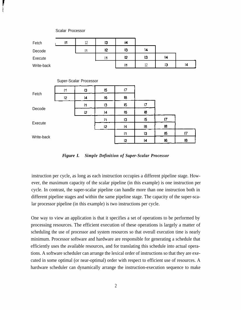
This thesis is concerned with single-processor hardware architectures that allow a sustainedexecution rate of more than one instruction per processor cycle: these are called a super-sca-lar architectures. Figure 1 is a simple comparison of the pipelines of a scalar and a super-scalar processor (Figure 1 shows an ideal instruction sequence, where all instructions areindependent of each other). The pipeline of the scalar processor can handle more than one
1
Fetch
Decode
Execute
Write-back
Fetch
Decode
Execute
Write-back
Scalar Processor
I I1 12 I3 14
I1 12 I3 14
I1 I2 13 I4
I1 12 I3 I4
Super-Scalar Processor
Figure I. Simple Definition of Super-Scalar Processor
instruction per cycle, as long as each instruction occupies a different pipeline stage. How-ever, the maximum capacity of the scalar pipeline (in this example) is one instruction percycle. In contrast, the super-scalar pipeline can handle more than one instruction both indifferent pipeline stages and within the same pipeline stage. The capacity of the super-sca-lar processor pipeline (in this example) is two instructions per cycle.
One way to view an application is that it specifies a set of operations to be performed byprocessing resources. The efficient execution of these operations is largely a matter ofscheduling the use of processor and system resources so that overall execution time is nearlyminimum. Processor software and hardware are responsible for generating a schedule thatefficiently uses the available resources, and for translating this schedule into actual opera-tions. A software scheduler can arrange the lexical order of instructions so that they are exe-cuted in some optimal (or near-optimal) order with respect to efficient use of resources. Ahardware scheduler can dynamically arrange the instruction-execution sequence to make
2

efficient use of resources. In either case, however, the schedule of operations is constrainedby data dependencies between instructions and by finite processing resources.
Generating and executing an instruction schedule does not intrinsically depend on the num-ber of instructions that can be performed in a single cycle. The capability to perform morethan one instruction per cycle simply makes it possible to more effectively use the availableresources than if instruction issue is limited to one instruction per cycle. Whether or not thiscapability is beneficial depends on scheduling successes of software and hardware.
Most of the published work on instruction schedulers concentrates on specific schedulingalgorithms which can be implemented by software or hardware. Software-based studiesusually assume minimal processor hardware in a system environment that is constrained tobe deterministic and thus permit software scheduling (such as by omitting data caches [Col-well et al. 19871). On the other hand, hardware-based studies usually assume minimal soft-ware support (sometimes even going so far as to claim that hardware scheduling is advanta-geous because it relieves the compiler of the burden of generating optimized code [Acosta etal. 19861). Both hardware and software studies typically focus on special-purpose applica-tions, such as vectorizable applications, which are generally easier to schedule than general-purpose applications.
This study uses trace-driven simulation to examine the question of whether the cost, com-plexity, and performance of hardware scheduling in a super-scalar processor justify its usefor general-purpose applications. To address a shortcoming of previous studies, this studyexamines a wide range of interactions and tradeoffs between processor components, ratherthan focusing on one specific organization or scheduling algorithm. The approach taken isto evaluate a number of architectural features both in terms of the hardware cost and the per-formance provided, and to suggest areas where performance is not very sensitive to hard-ware simplification. As a result, a number of design alternatives are presented. In an actualimplementation, design decisions would be further guided by the capabilities and limita-tions of the implementation technology.
Some of the hardware simplifications suggested in this thesis are the result of software sup-port, but only in cases where software can obviously provide this support. To limit the scopeof this study, software techniques are not addressed in detail. Cost andcomplexity are exam-ined in light of simplifications that software might provide, but no software techniques areused to increase performance. The reader interested in software scheduling is referred to:Foster and Riseman [ 19721, Charlesworth [ 19811, Fisher [ 19811, Rau and Glaeser [ 198 11,Fisher [1983], Hennessy and Gross [ 19831, Mueller et al. [ 19841, Weiss and Smith [ 19871,
3

Hwu and Chang [ 19881, Lam [ 19881, Wulf [ 19881, and Jouppi and Wall [ 19881. These ref-erences together give an overview of the capabilities and limitations of software schedulers.
This thesis begins by establishing the background of this study. Chapter 2 explains conceptsand terminology related to hardware instruction schedulers, and discusses the existing lit-erature. This introductory material motivates the current study.
Chapter 3 introduces the methodology of this study and proposes a super-scalar processorthat performs hardware scheduling. With ideal instruction fetching, the proposed processorcan realize a speedup of over two for general-purpose benchmarks. However, simple, realis-tic instruction fetching limits performance to well below a speedup of two.
Chapter 4 explains the causes of the instruction-fetch limitations and techniques for over-coming them. Although instruction-fetch limitations can be largely removed, instructionfetching still limits performance more than the execution hardware. This suggests a designapproach of simplifying the execution hardware in light of the instruction-fetch limitations.
Chapters 5 and 6 explore a number of different implementations of the super-scalar execu-tion hardware. Chapter 5 focuses on mechanisms for resolving data dependencies and sup-plying instructions with operands, and Chapter 6 focuses on hardware instruction schedul-ing. Both chapters are oriented towards limiting processor hardware without causing a sig-nificant reduction in performance.
Finally, Chapter 7 presents the conclusions of this study. A super-scalar processor achievesbest performance with a core set of features. These features are complex and interdepend-ent, and the removal of any single feature causes a relatively large reduction in performance.However, there are many possible hardware simplifications in other areas that do not reduceperformance very much. These simplifications provide a number of implementation alter-natives.
Chapter 2Background
Hardware instruction-scheduling-both with single-instruction issue and multiple-instruc-tion issue-has been the object of a number of previous investigations. This chapter de-scribes fundamental concepts related to hardware instruction-scheduling, and explores howthese concepts have been applied in published research investigations. These investigationsform the basis of the current research, either by providing ideas to explore or by indicatingfruitless approaches. However, these investigations also leave open a number of questionsthat are addressed in the current study. Previous studies do not address the effects of super-scalar techniques on general-purpose applications, focusing instead on scientific applica-tions. In addition, they do not address the effects of super-scalar techniques in the context ofthe compiler optimizations and the low operations latencies that characterize a RISC proces-sor.
2.1 Fundamental Concepts
There are two, independent approaches to increasing performance with hardware instruc-
tion scheduling. The first is to remove constraints on the instruction-execution sequence bydiminishing the relationship between the order in which instructions are executed and theorder in which they are fetched. The second is to remove conflicts between instructions byduplicating processor resources. Either approach, not surprisingly, incurs hardware costs.
2.1.1 Instruction Scheduling Policies
The simplest method for scheduling instructions is to issue them in their original programorder. Instructions flow through the processor pipeline much as they do in a scalar proces-sor: the primary difference is that the super-scalar pipeline can execute more than one in-struction per cycle. Still, though the super-scalar processor can support a higher instruction-execution rate than the scalar processor, the super-scalar pipeline experiences more opera-tion dependencies and resource conflicts that stall instruction issue and limit concurrency.
Figure 2 illustrates the operation of the super-scalar processor when instructions are issuedin-order and complete in-order. In this case, the pipeline is designed to handle a certainnumber of instructions (Figure 2 shows two instructions), and only this number of instruc-tions can be in execution at once. Instruction results are written back in the same order thatthe corresponding instructions were fetched, making this a simple organization. Instruction
5

Decode
Execute
Write-back
Notes:I1 requires two cycles to execute13 and 14 conflict for functional unitI5 depends on I4
Total number of cycles = 8
I5 and I6 conflict for functional unit
Figure 2. Super-Scalar Pipeline with In-Order Issue and Completion
issuing is stalled when there is a conflict for a functional unit (the conflicting instructions arethen issued in series) or when a functional unit requires more than one cycle to generate aresult.
Figure 3 illustrates the operation of the super-scalar processor when instructions are issuedin-order and complete out-of-order. In this case, any number of instructions is allowed to bein execution in the pipeline stages of the functional units, up to the total number of pipelinestages. Instructions can complete out-of-order because instruction issuing is not stalledwhen a functional unit takes more than one cycle to compute a result: a functional unit may
Decode
Execute
W&e-back
Notes:I1 requires two cycles to executeI3 and I4 conflict for functional unit15 depends on I4
Total number of cycles = 7I1 completes out-of-order
I5 and I6 conflict for functional unit
Figure 3. Super-Scalar Pipeline with In-Order Issue and Out-of-Order Completion
6

1
complete an earlier instruction after subsequent instructions have already completed. In-struction issuing is stalled when there is a conflict for a functional unit, when a required func-tional unit is not available, when an issued instruction depends on a result that is not yet com-puted, or when the result of an issued instruction might be later overwritten by an older in-struction that takes longer to complete.
Completing instructions out-of-order permits more concurrency between instructions andgenerally yields higher performance than completing instructions in-order. However, out-of-order completion requires more hardware than in-order completion:
l Dependency logic is more complex with out-of-order completion, becausethis logic checks data dependencies between decoded instructions and all in-structions in all pipeline stages. The dependency logic must also insure thatresults are written in a correct order. With in-order completion, dependencylogic checks data dependencies between decoded instructions and the fewinstructions in execution (for the purpose of forwarding data upon instruc-tion completion), and results are naturally written in a correct order.
l Out-of-order completion creates a need for functional units to arbitrate forresult buses and register-file write ports, because there are probably notenough of these to satisfy all instructions that can complete simultaneously.
Out-of-order completion also complicates restarting the processor after an interrupt or ex-ception, because, by definition, an instruction that completes out-of-order does not modifyprocessor or system state in a sequential order with respect to other instructions. One ap-proach to restaR relies on processor hardware to maintain a simple, well-defined restart statethat is consistent with the state of a sequentially-executing processor [Smith and Pleszkun19851. In this case, restarting after a point of incorrect execution requires only a branch (orsimilar change of control flow) to the point of the exception, after the cause of the exceptionhas been corrected. A processor providing this form of restart state is said to support preciseinterrupts orprecise exceptions. Alternatively, the processor pipeline state can be made ac-cessible by software to permit restart [Pleszkun et al. 19871.
Regardless of whether instructions complete in-order or out-of-order, in-order issue limitsperformance because there is a limited number of instructions to schedule. The flow of in-structions is stalled whenever the issue criteria cannot be met. An alternative is to provide arelatively large set of instructions to be executed-in an instruction window-from whichindependent instructions are selected for issue. Instructions can be issued from the window

with little regard for their original program order, so this method can issue instructions our-of-or&r. Figure 4 illustrates the operation of a super-scalar pipeline with out-of-order issue.
The instruction window is not an additional pipeline stage, but is shown in Figure 4 as ascheduling mechanism between the decode and execute stages for clarity. The fact that aninstruction is in the window implies that the processor has sufficient information about theinstruction to make scheduling decisions. The instruction window can be formed by some-how looking ahead at instructions to be executed [Wedig 19821, or by fetching instructionssequentially into the window and keeping them in the window as long as they cannot be exe-cuted.
2.1.2 Scheduling Constraints
Regardless of the sophistication of the scheduling policy, performance is ultimately limitedby other constraints on scheduling. These constraints fall into four basic categories:
l Procedural dependencies. If all instructions to be scheduled were known atthe beginning of execution, very high speedups would be possible [Risemanand Foster 1972, Nicolau and Fisher 19841. Unfortunately, branches causeambiguity in the set of instructions to be scheduled. Instructions following abranch have a procedural dependency on the branch instruction, and cannotbe completely executed until the branch is executed.
l Resource conflicts. Instructions that use the same shared resources cannot beexecuted simultaneously.
Decode
Window
Execute
Write-back
: II, 12 : 13,14 : 14,15,l6 : 15 :\ l
I1 I1 14 -
I2 13 I6 I5
I1 I6 -
12 I3 I4 I5
Notes:I1 requires two cycles to executeI3 and I4 conflict for functional unitI5 depends on 14I5 and I6 conflict for functional unit
Total number of cycles = 6I1 and I6 complete out-of-orderI6 issues out-of-order
Figure 4. Super-Scalar Pipeline with Out-of-Order Issue and Completion
8

l True data dependencies (or true dependencies). An instruction cannot beexecuted until all required operands are available.
l Storage conflicts. Storage locations (registers or memory locations) arereused so that, at different points in time, they hold different values for differ-ent computations. This can cause computations to interfere with one anothereven though the instructions are otherwise independent [Backus 19781. Theterm “storage conflict” is not in widespread use, but is more descriptive ofthe scheduling constraint than other terms in general use. There are twotypes of storage conflicts: anti-dependencies and output dependencies (thereis little standardization on the terminology used to denote these dependen-cies, but the concepts are the same in any case). Anti-dependencies enforcethe restriction that a value in a storage location cannot be overwritten until allprior uses of the value have been satisfied. Output dependencies enforce therestriction that the value in a storage location must be the most recent assign-ment to that location.
Procedural dependencies and resource conflicts are easily understood, and are not discussedfurther in this section (although they are considered in the remainder of this thesis). Truedependencies are often grouped with storage conflicts, in the literature, into a single class ofinstruction dependencies. However, it is important to distinguish true dependencies fromstorage conflicts, because storage conflicts can be reduced or removed by duplicating stor-age locations, much as other resource conflicts can be reduced or removed by duplicatingresources.
The distinction between true, anti-, andoutput dependencies is easily illustrated by an exam-ple:
R3 := R3 op R5 (1)R4 := R3 + 1 (2)R3 := R5 + 1 (3)R7 : = R 3 o p R 4 (4)
In this example:
l The second instruction cannot begin until the completion of the assignmentin the first instruction. Also, the fourth instruction cannot begin until thecompletion of the assignments in the second and third instructions. The firstinput operand to the second instruction has a true dependency on the resultvalue of the frost instruction, and the input operands to the fourth instructionhave true dependencies on the result values of the second and third instruc-tions.
9
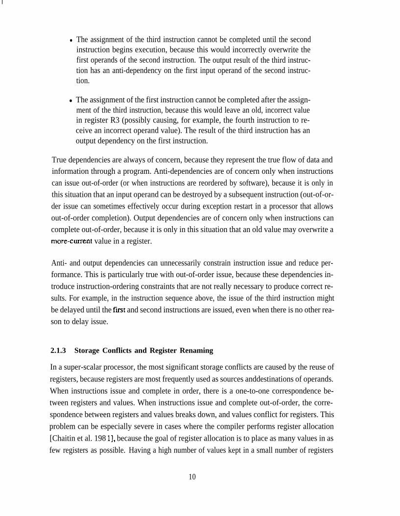
l The assignment of the third instruction cannot be completed until the secondinstruction begins execution, because this would incorrectly overwrite thefirst operands of the second instruction. The output result of the third instruc-tion has an anti-dependency on the first input operand of the second instruc-tion.
l The assignment of the first instruction cannot be completed after the assign-ment of the third instruction, because this would leave an old, incorrect valuein register R3 (possibly causing, for example, the fourth instruction to re-ceive an incorrect operand value). The result of the third instruction has anoutput dependency on the first instruction.
True dependencies are always of concern, because they represent the true flow of data andinformation through a program. Anti-dependencies are of concern only when instructionscan issue out-of-order (or when instructions are reordered by software), because it is only inthis situation that an input operand can be destroyed by a subsequent instruction (out-of-or-der issue can sometimes effectively occur during exception restart in a processor that allowsout-of-order completion). Output dependencies are of concern only when instructions cancomplete out-of-order, because it is only in this situation that an old value may overwrite amore-cutrent value in a register.
Anti- and output dependencies can unnecessarily constrain instruction issue and reduce per-formance. This is particularly true with out-of-order issue, because these dependencies in-troduce instruction-ordering constraints that are not really necessary to produce correct re-sults. For example, in the instruction sequence above, the issue of the third instruction mightbe delayed until the fust and second instructions are issued, even when there is no other rea-son to delay issue.
2.1.3 Storage Conflicts and Register Renaming
In a super-scalar processor, the most significant storage conflicts are caused by the reuse ofregisters, because registers are most frequently used as sources anddestinations of operands.When instructions issue and complete in order, there is a one-to-one correspondence be-tween registers and values. When instructions issue and complete out-of-order, the corre-spondence between registers and values breaks down, and values conflict for registers. Thisproblem can be especially severe in cases where the compiler performs register allocation[Chaitin et al. 198 11, because the goal of register allocation is to place as many values in asfew registers as possible. Having a high number of values kept in a small number of registers
10

1
creates a higher number of conflicts when the execution order is changed from the order as-sumed by the register allocator [Hwu and Chang 19881.
A hardware solution to these storage conflicts is for the processor to provide additional reg-isters which are used to reestablish the correspondence between registers and values. Theadditional registers are allocated dynamically by hardware, using register renaming [Keller19751. With register renaming, a new register is typically allocated for every new assign-ment. When one of these additional registers is allocated to receive a value, an access usingthe original register identifier obtains the value in the newly-allocated register (thus the reg-ister identifier is renamed to identify the new register). The same register identifier in sev-eral different instructions may access different hardware registers, depending on the loca-tions of register references with respect to register assignments.
With renaming, the example instruction sequence of Section 2.1.2 becomes:
R3b := R 3 . o p R5. (1)R4b := R3b + 1 (2)
:= R5. + 1;;& := (3)R3c Op R4b (4)
In this sequence, each assignment to a register creates a new instance of the register, denotedby an alphabetic subscript. The creation of new instances for R4 and R3 in the second andthird instructions avoids the anti- and output dependencies on the first and second instruc-tions, and yet does not interfere with correctly supplying operands to the fourth instruction.
Hardware that performs renaming creates each new register instance and destroys the in-stance when its value is superseded and there are no outstanding references to the value.This removes anti- and output dependencies, and allows more instruction concurrency.Registers are still reused, but reuse is in line with the requirements of concurrent execution.
2.2 Published Techniques for Single-Instruction Issue
This section explores how the concepts and techniques described in Section 2.1 have beenaddressed by published proposals for hardware scheduling with single-instruction issue.The goal of these proposals is to attempt to achieve an instruction-execution rate of one in-struction per cycle with functional units which can take several cycles to produce a result.The primary shortcoming of single-instruction schedulers with regards to the current studyis that they (as expected) do not address problems related to multiple-instruction issue. Sin-gle-instruction issue greatly reduces the burden on the scheduling logic, because this logicgenerally deals with instructions one-at-a-time.
11

2.2.1 Common Data Bus-Tornado’s Algorithm
Tomasulo [1967] describes the hardware scheduling algorithm implemented in the IBM360/91. There are two key components supporting this scheduling algorithm: reservationstations and a common data bus. The reservation stations appear at the input of each func-tional unit, and hold instructions which are waiting on operands or on the availability of theassociated functional units. The common data bus carries operands from the output of thefunctional units to the reservation stations: it is important that all functional units share thiscommon data bus so that operands may be broadcast to all reservation stations.
Tomasulo’s algorithm implements register renaming. When an instruction is decoded, it isallocated a reservation-station entry (decoding stalls if there is no available entry). Instruc-tion operands-or tags for these operands, if they are not available-are copied to the reser-vation-station entry. This copying avoids anti-dependencies, because subsequent instruc-tions can complete and write their results without disrupting either the operands or the tagsof this instruction.
To complete instruction decode, the identifier for the allocated reservation-station entry iswritten into a tag location associated with the result register (if the instruction has a result).This tag identifies the result that will be produced by this instruction, and serves to renamethe corresponding register. Any subsequent instruction that is decoded before the currentinstruction completes obtains this tag instead of an operand value. An instruction is issuedfrom the reservation station when all of its operands are valid (that is, when no tags are heldinstead of values) and the functional unit is free. When an instruction completes, its resultvalue is broadcast on the common data bus, along with the tag value (in reality, the tag isbroadcast on the preceding cycle, for timing reasons). All reservation-station entries thathave an operand tag equal to this result tag latch the result value, because this value is re-quired as an operand. The result value may also be written into the register file, but only if itstag matches the tag associated with the register. This avoid output dependencies: if the tagsdo not match, the result does not correspond to the most recent pending update to the regis-ter.
Exceptions are imprecise in this scheme because the sequential-execution state is not main-tained in the register file, and there is no provision to recover this state. However, exceptionsthat are detected during instruction decode (such as invalid instruction codes) are precise.Exceptions detected during decode can be made precise simply by holding instruction de-code and allowing all pending instructions to complete.
12
2.2.2 Derivatives of Tornado’s Algorithm
Weiss and Smith [ 19841 study the performance advantages of Tomasulo’s algorithm for theCRAY- 1 scalar processor, using the Lawrence Liver-more Loops as benchmarks. With sin-gle-instruction issue, Tomasulo’s algorithm yields a 1.58 average speedup. Weiss andSmith also propose and explore two simpler alternative hardware-scheduling mechanisms.
The first alternative to Tomasulo’s algorithm is based on Thorton’s [ 19701 register score-board used in the CDC6600. Weiss and Smith examine a variant of Thorton’s algorithm thateliminates renaming and the associated tag-allocation hardware of Tomasulo’s algorithm.Weiss and Smith’s variant of Thorton’s algorithm operates in a similar manner toTomasulo’s algorithm, except that a single bit (the scoreboard bit) is used instead of a tag toindicate that a register has a pending update. This eliminates the tag array and replaces itwith a simpler scoreboard array. Since there is only one bit to track pending register updates,there can be only one such update, and decoding is stalled if the decoded instruction wiIlupdate a register that already has a pending update. This further simplifies the hardware,because when there can be only one pending update there is no need to compare result tags toregister tags during write-back. Also, register identifiers are used instead of operand tags tomatch result values to operand values in the reservations stations. The disadvantage ofThorton’s algorithm is its performance: Tomasulo’s algorithm has 22% better performancefor the Livermore Loops, on the average.
A second simplification to Tomasulo’s algorithm examined by Weiss and Smith is a mecha-nism they term direct tag search, which eliminates the reservation-station comparators formatching result tags to operand tags. Direct tag search is used in a hardware organizationvery similar to that OfTomasulo’s, except that there is a table indexed by result tags to per-form the routing function that is performed, in Tomasulo’s algorithm, by the reservation-sta-tion comparators. In direct tag search, there can be only one reference to a given taggedvalue in a reservation-station entry; a second attempted reference blocks instruction decod-ing. When a tag is placed into a reservation-station entry, an identifier for that entry is placedinto the tag-table entry indexed by the tag. When the result corresponding to this tag is pro-duced, the tag is used to access the tag table, and the reservation-station identifier in the tableused to route the result value to the reservation station. This has about an 8% advantage overThorton’s algorithm, on the average.
Sohi and Vajapeyam [ 19871 address another undesirable feature of Tomasulo’s algorithm:there is a tag entry and comparator for each register, but this hardware is under-utilized.There are not many instructions in the reservation stations at any given time, and thus there
13

are not many active tags in the tag array. This is particularly a problem with a processorhaving a large number of registers (Sohi and Vajapeyam are concerned with the CRAY-1scalar processor, which has 144 registers). As an alternative, they propose keeping alI activetags in a much smaller associative array- t h e rag unit-that maintains alI register-to-tagmappings currently in effect. When an instruction is decoded, and one or both of its sourceregisters have pending updates (indicated by a single bit accessed with the source registers),the tag unit is queried with source-register identifiers and returns the appropriate tag(s). Atthe same time, a new tag is allocated for the current result, and this is placed into the tag unitalong with the destination-register identifier. If there is another pending update for the sameregister in the tag array, this previous update is marked as not being the latest update, toavoid output dependencies.
Sohi and Vajapeyam [ 19871 also examine several extensions to the tag unit. The first exten-sion follows the observation that each tag entry in the tag unit is associated with a singleinstruction in a reservation station. Because of this one-to-one correspondence between tag-unit entries and reservation-station entries, the tag unit and reservation stations can be com-bined into a single reservation station/tag unit (RSTU) that serves as a reservation station forall functional units. This has the advantage that less storage is needed, because the reserva-tion station is not partitioned by functional unit. Furthermore, the storage in the RSTU canbe used to hold results after instruction completion, and can return the results to the registerfile in sequential order. This configuration, called a register update unit (RW), providesprecise interrupts. The RW is operated as a first-in, first-out (FIFO) buffer, with decodedinstructions being placed at the tail of the FIFO and results being written from the head of theFIFO.
Updating the registers sequentially allows variations in the tag-allocation hardware. If re-sults are returned to registers in order, countexs can be used to keep track of pending updates.Sohi and Vajapeyam associate two counters with each register: one counter keeps track ofthe number of values destined for the register (the number of instances counter), and theother keeps track of the most recent value (the latesr instance counter). The latest instancecounter-appended to the register identifier- acts as a tag for the operand. The number ofinstances counter prevents the number of pending updates from exceeding the limitations ofthe latest instance counter and thus prevents duplication of tags (this could be accomplishedmore simply by making the latest instance counter big enough to count every entry in theRW). It is not clear that these counters are much simpler than the tag logic they are intendedto avoid.
14

Sohi and Vajapeyam find that their configuration has a speedup of 1.81 for the LawerenceLivermore Loops with a register update unit of 50 entries. The CRAY-1 configuration theyuse has high operation latencies which reduce the advantage of hardware scheduling.
2.3 Published Techniques for Multiple-Instruction Issue
This section expIores how the concepts and techniques described in Section 2.1 have beenaddressed by published proposals for hardware scheduling with multiple-instruction issue.In contrast to single-instruction schedulers, multiple-instruction schedulers are in a moretheoretical domain. Most of the proposals discussed below concentrate on scheduling algo-rithms and are light in their treatment such issues as efficient instruction fetching, the com-plexity and speed of the dependency-checking logic, and the allocation and deallocation ofprocessor resources when a variable number of instructions issue and complete in a singlecycle.
2.3.1 Detecting Independent Instructions with a Pre-Decode Stack
The original work on hardware scheduling for multiple-instruction issue appears to havebeen by Tjaden and Flynn [1970]. They describe a method for detecting independent in-structions in a pre-decode stack, considering only data dependencies between instructions.Branch instructions are not considered: it is assumed that procedural dependencies havebeen removed before the instructions are placed into the pre-decode stack.
In Tjaden and Flynn’s proposal, instructions are encoded so that instruction source and sinkregisters are identified by bit vectors within the instructions-it is contemplated that theprocessor has only a few such sources and sinks, as in an accumulator-based architecture.Dependencies between instructions in the pre-decode stack are determined by comparingthese source and sink vectors bit-by-bit on every cycle, causing the dependency-checkinglogic to grow as the square of the size of the pre-decode stack. The algorithm checks for trueand anti-dependencies, but completely ignores output dependencies. Apparently, it is as-sumed that a value will be used as a source operand before it is overwritten, and that all in-structions complete in the same amount of time. The algorithm also defines weakly inde-pendent instructions which use different registers but which may generate a common mem-ory address and thus depend through memory locations.
The scheduling algorithm implements renaming by a special treatment of instructions hav-ing open fleers. An instruction has open effects if it updates a register on which it does notdepend-this is simply the property an instruction must have for renaming to be
15

advantageous. To support renaming, each register is statically duplicated a number of times,so that each program-visible register is actually implemented as a vector of registers. Whenan open-effects instruction is found in the pre-decode stack, its destination register is reas-signed to be the next adjacent register in the register vector, all instructions following thisinstruction then use the newly-assigned register, until a new open-effects instruction is en-countered which updates this register.
Tjaden and Flynn find that, with renaming, the algorithm has a potential speedup of 1.86.However, this measurement was made for only 5600 instructions, and is based only on thenumber of independent instructions in the predecode stack. This speedup does not accountfor effects of instruction fetching, instruction-execution time, nor increased decoding time.
2.3.2 Ordering Matrices
Tjaden [ 19721 and Tjaden and Flynn [ 19731 describe a (rather theoretical) scheduling tech-nique for issuing multiple instructions based on software-generated dependency matrices.Each row or column of a dependency matrix is a bit vector that identifies the sources or sinksof instructions in a program. There are two principal matrices. The first matrix has rowsmade up of the bit vectors that identify instruction sinks: a bit is set in a row if the instructioncorresponding to the row alters the register corresponding to the bit. The second matrix hascolumns made up of bit vectors that identify instruction sources: a bit is set in a column if theinstruction corresponding to the column reads the register corresponding to the bit. Depend-encies between instructions are detected by performing operations on these matrices. As inTjaden and Flynn [ 19701, it is unclear how output dependencies are handled.
The dependency matrices are assumed to be computed by a software preprocessor andloaded into the processor before execution. For this reason, the algorithm cannot handle de-pendencies that are detected via dynamically-computed addresses. Furthermore, elementsof the matrix are activated and deactivated by hardware to enable and disable portions of thedependency-checking as instructions are completed and reactivated (reactivation occurs be-cause of branches). Because of activation and deactivation, matrix elements can have threevalues: off (the source or sink is not used), on/active (the source or sink will be used), andon/inactive (the source of sink will not be used because the instruction is not active, but maybe used at a later time). The algorithm handles procedural dependencies by making this acti-vation/deactivation information explicitly visible as storage, called the IC resources. Allbranch instructions update the IC resources to activate and deactivate instructions, and allinstructions use the IC resources as a source. Procedural dependencies are thus treated asdata dependencies on the IC resources. This causes all instruction preceding a branch to
16

1
issue before the branch is issued, and causes a branch to issue before instructions after thebranch am issued (although the algorithm can be enhanced in several ways to relax theseconstraints).
Register renaming is performed as in Tjaden and Flynn [ 19701 by providing statically-dupli-cated registers. In this case, however, renaming is applied to instructions having shadoweffects. The term shadow effects refers to an instruction with an antidependency on a previ-ous instruction: this instructions can be made independent by reassigning the instructionsink. Renaming requires five-value matrix elements: off, on/active, on/inactive, shadoweffects/active (the instruction is independent if the sink can be reassigned), and shadow ef-fects/inactive. Handling shadow effects in this manner has the further disadvantage of creat-ing false dependencies, because the dependency matrices do not take renaming into account.
The speedup for the highest-performing version of this algorithm is 1.98 on a sample of threebenchmarks. However, this speedup does not account for the complexity of the schedulingalgorithm. An implementation with 36-by-36 matrices requires 1296 total elements in eachmatrix, and 3 bits of storage at each element. Performing the required matrix operations andupdates takes 4 micro-seconds, assuming six-input gates with a propagation delay of 5 nanoseconds each. Even at this, the algorithm can handle only tasks that are 36 instruction long orless. Larger tasks are handled by hierarchically breaking the tasks into smaller sub-tasks andusing the algorithm to schedule these sub-tasks.
2.3.3 Concurrency Detection in Directly-Executed Languages
Wedig [ 19821 builds on the the work Tjaden [ 19721 and Tjaden and Flynn [ 19731, address-ing primarily the weaknesses in handling procedural dependencies and in fetching tasks intothe instruction window. Wedig’s scheduling algorithm assumes instructions are in theiroriginal static order in the instruction window. This algorithm is presented in the context of adirectly-executed-language architecture, but this limitation seems unnecessary other than toallow some assumptions about how instruction and task information are encoded.
Wedig assumes the existence of a resource conflict function returning a set of independentinstructions (this function has the complexity of Tjaden’s and Flynn’s ordering matrices).Procedural dependencies are handled by associating with each instruction in the window aexecution vector that indicates how many iterations of the instruction have been executed. Aglobal to-be-executed element defines the total number of iterations to be performed by allinstructions in the window. This approach initially assumes that all instruction in the win-dow will be performed the same number of times (conceptually equal to the highest number
17

of iterations in the window). Instructions that art not actually executed this number of timesare vimalfy executed by updating their execution vector without actually executing the in-struction. The execution vector and the to-be-executed vector are computed dynamically asthe result of branch instructions. The static instructions i,n the window can thus providemany dynamic instructions. Several branches can be executed in parallel, because these si-multaneously update the to-be-executed vectors. Wedig also examines the problems relatedto filling the instruction window, but this amounts to little more than enumerating the prob-lems encountered and defining the functions that must be performed to update the executionstructures.
Wedig implements register renaming by associating a shadow storage queue with each in-struction in the window. The shadow storage queue consists of three vectors. There is onesew sink vector; an element of this vector is the value produced by the correspondingiteration of the instruction, and there is one element per iteration (over a local span of time).There are two shadow source vectors; elements of these vectors point to source operands, inthe shadow sink vectors, of the corresponding instruction iterations. The shadow storagequeue unnecessarily duplicates resources, and further complicates the scheduling algo-rithm. With renaming, Wedig’s algorithm achieves a speedup of 3.00, assuming compilersupport to help create independent instructions.
Uht [ 19861 builds on Wedig’s work, and reduces hardware required by building dependencymatrices as instructions are loaded into the window rather than after instructions are loadedinto the window. Uht also identifies classes of procedural dependencies that are avoided bythe static instruction window (for example, nested forward branches can be executed inde-pendently, because the execution of these involves only updating the to-be-executed vec-tors). With renaming, Uht obtains an average speedup of 2.00 over ten benchmarks.
2.3.4 Dispatch Stack
Tomg [ 19841 and Acosta et al. [ 19861 propose a dispatch stack that detects independent in-structions and issues them to the functional units. The dispatch stack is an instruction win-dow that has source- and destination-register fields augmented with dependency counts.There is a dependency count associated with each source register, giving the number ofpending updates to the source register (thus the number of updates which must be completedbefore all possible true dependencies are removed). There are two similar dependencycounts associated with each destination register, giving both the number of pending uses ofthe register (the number of anti-dependencies) and the number of pending updates to the reg-ister (the number of output dependencies). When an instruction is loaded into the dispatch
18

stack, these counts are set by comparisons of register identifiers with all instructions alreadyin the dispatch stack (requiring five comparators per loaded instruction per instruction in thedispatch stack). As instructions complete, the dependency counts are decremented (by avariable amount) based on the source- and destination-register identifiers of completing in-structions (also requiring five comparators per completed instruction per instruction in thedispatch stack). An instruction is independent when all of its counts are zero, and can beissued if it has no functional-unit conflicts.
The dispatch stack achieves a speedup of 2.79 for the Lawrence Livermore Loops, on anideal processor that has an infinite number of single-cycle functional units and infinite in-struction-fetch bandwidth. The performance of this machine could be much higher: per-formance suffers because this algorithm does not implement register renaming. This is un-fortunate, because the comparators used to detect dependencies and to update dependencycounts could be put to better use by implementing renaming. Also, a branch is handled bystalling the instruction fetcher until the branch is resolved. This apparently does not affectperformance very much, because in the Livermore Loops the branch dependency path isshorter than other dependency paths. Dwyer and Tomg [ 19871 address issues of hardwarecomplexity and performance with the dispatch stack, relying on bit vectors to select tegis-ters.
2.3.5 High Performance Substrate
The High Performance Substrate (HPS) [Patt et al 1985a] and the proposed single-chip im-plementation HPSm [Hwu andPatt 19861 are concerned with scheduling micro-instructionsthat have been decoded from higher-level instructions. The motivation for the word “sub-strate” in the project name is that this architecture can form the basis for emulating any in-struction set-via micro-code interpretation- with presumed good performance because ofthe ability to exploit micro-code-level concurrency.
In HPS, a “branch predictor” supplies instructions to adecoder (the most explicit discussionof the branch predictor appears in [Patt et al. 1985b], but this is not very specific). The de-coder then expands instructions into sets of nodes. The tetm “node” refers to a node in adependency sub-graph for the instruction. A node is basically a micro-instruction, and thenodes (microinstructions) corresponding to a given instruction have interdependencies ex-plicitly identified. After decoding, nodes are merged into a node table using Tomasulo’salgorithm The merge operation resolves dependencies on nodes outside of the decoded set,supplying either values or tags for required operands; a regisrer alias table implements re-naming. After merging, the nodes are placed into a node table which serves the same role as
19

reservation stations, except that there is a single node table for ail functional units instead ofa node table per functional unit. Nodes are issued from the node table to the functional units.A checkpoint mechanism deals with exceptions and repairing processor state aftermispredicted branches [Hwu and Patt 19871.
The proposed HPS hardware is quite complex and general, addressing several concerns notdirectly related to scheduling or concurrent execution. For example, interpreting higher-level instructions creates a need to identify the point at which all micro-operations for agiven instruction have completed, because only at this time is the entire instruction com-plete.
Hwu and Patt [ 19861 compare the performance of HPSm to the Berkeley RISC II processor.The performance of HPSm is better than the performance of RISC II, but this is mostly theresult of assuming a 100 nano-second cycle time for HPSm against a 330 nanosecond cycletime for RISC II (this is justified on the basis of pipelining). On a cycle-by-cycle basis,HPSm is slower than RISC II in four of six benchmarks, with optimized code.
2.3.6 Multiple-Instruction Issue with the CRAY-1 Architecture
Plezkun and Sohi [ 19881 describe the performance of the CRAY-1 scalar architecture onthe Lawrence Liver-more Loops. They simulate several combinations of result-bus organi-zations, issue policies (in-order, out-of-order), and operation latencies. Register renaming,with the register update unit of Sohi and Vajapeyam [ 19871, is also examined. None of thesealternatives achieves an instruction-execution rate greater than unity on scalar code, but thisis probably due to the high latency of the functional units and of the memory (a load requireseleven or five cycles to execute, and a branch requires five or two cycles, depending on themachine organization). The high latency is reflected in the fact that, for this organization,the maximum theoretical execution rate is .79-l .29 instructions per cycle, Issuing four in-structions per cycle with renaming and out-of-order execution achieves 6449% of thismaximum. However, single-instruction issue with renaming and out-of-order executionachieves 5662% of the theoretical maximum-close to the performance with multiple-in-struction issue. Limitations on performance that are unrelated to the scheduling mechanismmake it difficult to determine the effectiveness multiple-instruction scheduling in this case.
2.4 Observations and Conclusions
Much of the previous research is not directly relevant to a super-scalar RISC processor, fortwo reasons. First, this research was based on architectures with high operation latencies-
20

or, worse, unstated operation latencies-which blurs the relationship between instructionscheduling and performance. A RISC processor is typically characterized by very low laten-ties for most operations. Second, the effect of compiler optimizations is often ignored inprevious studies, even though these optimization can reduce instruction independence[Jouppi and Wail 19881. For example, moving an invariant instruction out of a loop caneliminate many independent run-time operations.
Previous studies have focused on scientific applications having a high degree of independ-ent computation. Simply having the capability to issue floating-point instructions concur-rently with other instructions gives the super-scalar processor the same high instructionthroughput, on vectorizable code, as a vector processor. In some scientific applications, asuper-scalar processor can be superior to a vector processor, because the super-scalar proc-essor does not incur as much of the pipeline-startup latency associated with the vector proc-essor [Agerwala and Cocke 19871.
In contrast, the current study is oriented towards applications having widespread use ongeneral-purpose, single-chip RISC microprocessors. These applications are significantlydifferent than scientific applications. There is less opportunity for concurrent execution ofoperations than there is in scientific programs. Furthermore, hardware costs are a muchlarger consideration in general-purpose computing than in high-performance scientificcomputing.
Finally, previous studies provide many ideas for implementing an effective execution unit,but say very little about supplying instructions to the execution unit at an adequate rate. Thisstudy will show that instruction fetching is the most severe performance limit in the super-scalar processor, and that the design of the execution unit should take this into account.
21
Chapter 3Methodology and Potential Performance
Prior hardware-scheduling studies are a good source of i&as, but these studies do not pro-vide much information on which to base implementation decisions. All research describedin the previous chapter concentrates on specific scheduling algorithms, and evaluate imple-mentation tradeoffs only within the context of the given algorithm. The current study, incontrast, explores a wide range of design tradeoffs presented by a super-scalar processor,using highly-optimized, general-purpose benchmark programs. The methodology was de-signed to allow the efficient evaluation of a large number of hardware alternatives on a largeclass of programs.
This chapter introduces the methodology of this research. This chapter also develops, as abasis for investigation, a super-scalar RISC processor model used to evaluate potential per-formance. The performance achieved by this processor model-for perfectly-predictedbranches and infinite instruction bandwidth-is over twice the performance of a scalar proc-essor that issues single instructions in order. This speedup is limited by data dependencies,resource conflicts, and the limited number of instructions available to the hardware sched-uler. However, as will be shown, instruction-fetch limitations constrain the performance ofthe super-scalar processor more than instruction-scheduling constraints. The followingchapter considers methods for improving the efficiency of the instruction fetcher.
3.1 Simulation Technique
This study uses a trace-driven simulation to evaluate the benefits of various super-scalar or-ganizations for highly-optimized, non-scientific applications. The tracing system is basedon the MIPS, Inc. R2000TM RISC processor (1). The R2000 has very good optimizing com-pilers, as well as analysis tools which allow generation of dynamic instruction traces anddata-reference traces NIPS 861.
All simulations are performed as shown in Figure 5. The optimized object code for a par-ticular benchmark is processed by pixieTM (1) [MIPS 861, a program that annotates the ob-ject code at basic-block entry points and at memory references. When the annotated code isexecuted, it produces a dynamic trace stream in addition to the program’s normal output.This trace stream consists of basic block addresses, counts of the number of instructions in
(1) R2000 and pixie are trademarks of MIPS, Inc.
22

Trace Stream \t lnstfuction
Anno ta ted w Lookup andObject File- Decoding
I
ObjectFile
I SchedulingParameters
Figure 5. Flowchart for Trace-Driven Simulation
each basic block, and load/store addresses. The trace stream and the original object file areused to generate the full instruction trace stream needed by the hardware simulator. Thisapproach allows statistics to be generated rapidly, and allows the super-scalar evaluation tobe performed at a reasonable level of abstraction. For example, the simulator need not trackthe contents of every processor register, it is only necessary that the simulator be aware ofregister identifiers in instructions. Furthermore, the simulator need only model the func-tional units as nodes representing delay.
The machine simulator models the functionality of both a super-scalar and a scalar processorusing a machine configuration file and command-line scheduling parameters. The execu-tion of the scalar and super-scalar processors are modeled at a functional level, with timerecorded in terms of machine cycles. The cycle time and functional-unit characteristics ofthe two processors are identical, although the super-scalar processor has two integer arith-metic/logic units (ALUs), which reduces the principle resource constraint to concurrent
23
instruction execution. Most instructions in the benchmark programs (typically 50%) areperformed by an integer ALU, and providing two ALUs relieves the most severe resourcebottleneck [Smith et al. 19891.
The scalar and super-scalar processors differ primarily in the instruction decode and sched-uling mechanisms. The scalar processor issues instructions in-order and completes instruc-tions out-of-order, this permits a certain amount of concurrency between instructions (forexample, between loads and other integer operations). The super-scalar processor is able todecode and issue any number of instructions, using any issue policy (the actual processorconfiguration is specified upon program initiation). By keeping the number of instructionscompleted by each processor equal, the simulator is able to determine the performance ad-vantage of the super-scalar organization over the scalar processor in a way that is independ-ent of other effects, such as changes in cache reload penalties or functional-unit latencies.
As the simulator fetches instructions from the dynamic trace stream, it accounts for penaltieswhich would be associated with fetching these instructions in an actual implementation(such as instruction-cache misses) and supplies these instructions to the scalar and super-scalar processor models. Each processor model accounts for penalties caused by branchesand by the execution unit not being able to accept decoded instructions (because of resourceconflicts, for example). Instructions are checked for data and/or register dependencies on allother uncompleted instructions. When an instruction is issued, it flows through a simulatedfunctional-unit pipeline. The instruction cannot complete until it successfully arbitrates forone of (possibly) several result buses. During the cycle in which the result appears on a re-sult bus, all dependencies on the instruction are removed.
3.2 Benchmark Programs
The set of target applications has a significant influence on the available instruction inde-pendence and the resulting performance of the super-scalar processor. A significant portionof the published research strives to use super-scalar techniques to enhance the performanceof scientific or vectorizable applications. These applications typically have a high numberof independent operations and a high ratio of computation to dynamic branches. This in turnleads to large potential concurrency. In contrast, the programs used in this study mostly rep-resent a wide class of general, non-vectorizable applications (linpack is a notable excep-tion). These applications are thought to have little instruction-level concurrency because oftheir complex control flow, and they form a good test of the generality of the super-scalarprocessor.
24

The benchmarks include a number of integer programs (such as compilers and text format-ters) and scalar floating-point applications (such as circuit and timing simulators). Table 1describes each benchmark program. To avoid examining concurrency that is due to the lackof compiler optimization, highly-optimized versions of these programs are used. No soft-ware reorganization is performed, except for usual RISC pipeline scheduling already exist-ing in the code.
To obtain processor measurements, each program is allowed to complete 4 million instruc-tions. This reduces simulation time, and includes a fixed overhead for cache cold-start ef-fects in every measurement (roughly corresponding to 100-300 process switches per sec-ond, depending on the cycle time and execution rate of a particular configuration). In prac-tice, the results do not change significantly after the first million instructions.
Four programs in Table l-ccom, irsim, troff, and yacc-are chosen as a representativesample for demonstrating and clarifying certain points throughout this thesis. This sample
Program
5diff
Table I. Benchmark Program Descriptions
Description
text file comparison
awk 1 pattern scanning and processing Iccom
compress
doduc
optimizing C compiler
file compression using Lempel-Ziv encoding
Monte-Carlo simulation, double-precision floating--point
espresso logic minimization
gnuchess computer chess program
wwirsim
latex
reports occurrences of a string in one or more text files
delay simulator for VLSI layouts
document preparation system
linpack linear-equation solver, double-precision floating-pointI I
nroff 1 text formatter for a typewriter-like deviceI
simple
spice296
tmff
hydrodynamics code
circuit simulator
text formatter for typesetting device
wolfwhetstone
vacc
standard-cell placement using simulated annealing
standard floating-point benchmark, double-precision floating-point
comoiles a context-free arammar into LR(l) parser tables
25
limits the amount of data presented for purposes of illustration. Othenvise, simulation re-sults are presented as low, harmonic mean, and high values for all programs shown inTable 1. The harmonic mean is used to mote closely convey the expected speedup over allbenchmarks.
3.3 Initial Processor Model
Super-scalar processor design presents a large number of opportunities for tradeoffs. As
with any processor, there is much interaction between processor components, and this inter-action limits performance. However, the interaction is significantly more complex in a su-per-scalar processor than in a scalar RISC processor. The investigation of tradeoffs is sim-plified if there is a single basis for evaluation.
This section presents a model for a super-scalar execution unit that was culled from a varietyof hardware instruction-scheduling proposals. This model resulted from an investigationinto the performance limitations imposed by the execution hardware, and is a good startingpoint for this study because the model is rather ambitious and can exploit much of the concu-rrency available in the benchmark programs. Since this execution model does not limit per-formance appreciably, it allows a more straightforward exploration of performance limitsand design tradeoffs than would a processor having limited performance potential.
To develop this initial model, it was necessary to specify criteria for selecting among alter-native hardware organizations--in the absence of specific measurements-because of thevariety of existing super-scalar proposals and associated performance claims. This sectiondescribes the rationale behind the initial processor organization as well as the organizationitself. It should be emphasized that the rationale presented here is not necessarily universal:it simply introduces the considerations related to multiple-instruction issue and to hardwarescheduling, and motivates the hardware organization. The following chapters deal with ex-ploring, refining, and simplifying this model.
3.3.1 Basic Organization
Three organizational techniques allow the super-scalar processor to achieve as much in-struction-execution concurrency as possible. First, there are multiple, independent, func-tional units. This allows concurrent operation on different instructions. Second, the func-tional units that take more than one cycle to generate a result are pipelined where possible, sothat instructions can be issued at a higher rate than without pipelining. Third, the execution
26

unit can issue instructions out-of-order to allow the functional units to be better utilized inthe presence of data dependencies.
Figure 6 illustrates a cost/performance dilemma presented by a super-scalar processor.Figure 6 plots-for the sample benchmarks-the fraction of total cycles in which 0, 1,2,3,etc. instructions are issued in a processor with perfect instruction and data caches (a perfectcache is infinite and suffers no reload penalty). Figure 6 also shows the net instruction-exe-cution rate for these benchmarks. These data illustrate that the maximum number of instruc-tions issued in one cycle can be significantly higher than the aggregate instruction-issue rate(more than a factor of two higher). Hardware costs and performance are determined by thepeak instruction-execution rate, but the average execution rate is well below below this peakrate.
To avoid as many constraints as possible, the execution unit must support a high peak in-struction-execution rate. However, issuing many instructions per cycle can be quite expen-sive, because of the cost incurred in communicating operand values to the functional units.Each instruction issued in a single cycle must be accompanied by all its required operands,so issuing N instructions in one cycle requires access ports and routing buses for as many as2N operands. An apparently cost-effective way to support this peak instruction-issue rate is
Fraction ofTotal Cycles
Benchmark/Net Instruction-Execution RatecconV2.57 irsimQ.62 tmff#/2.58 yaccd2.39
0.320- I0.280 I
0.240
U’ 0 1 2 3 4 5 6+Number of Instructions
Figure 6. Sample Instruction-Issue Distribution
27
by distributing the instruction window among the functional units as reservation stations[Tomasulo 19671. With this organization, the reservation stations act as an instructionbuffer that is filled at the average instruction-execution rate. The decoder, register readports, and operand-distribution buses need only support the average rate. Because the mser-vation stations are distributed, they can easily support the maximum instruction-issue rate:in one cycle, the reservation stations can issue an instruction at each of the functional units.The data needed for instruction issue comes from the local reservation stations, rather than aglobal register file.
3.3.2 Implementation Description
Figure 7 shows a block diagram for the processor model. In Figure 7, connections betweencomponents should not be construed as single buses; almost all connections comprise multi-ple buses, as described later.
The processor incorporates two major operational units-an integer unit and a floating-point unit-which communicate data via a data cache and data memory. This organizationwas chosen to mimic the organization of the R2000 processor and the R2010TM (2) floating-point unit. The integer and floating-point units are controlled by a single instruction streamsupplied by an instruction memory via an instruction cache. Both the instruction memoryand the instruction cache can supply multiple instructions per fetch, but the number of in-structions fetched from the instruction memory is not necessarily equivalent to the numberof instructions fetched from the instruction cache.
Each operational unit is composed of a number of functional units with associated reserva-tion stations. A multiple-instruction decoder places instructions and operands into the reser-vation stations of the appropriate functional units. A functional unit can issue an instructionin the cycle following &ode if that instruction has no data dependencies and the functionalunit is not busy; otherwise, the instruction is stored in the reservation station until all depend-encies are released and the functional unit is available.
Register renaming [Keller 19751 eliminates anti- and output dependencies. To implementregister renaming, each operational unit incorporates a reorder buffer [Smith and Pleszkun19851 containing a number of storage locations which are dynamically allocated to instruc-tion results. When an instruction is decoded, its result value is assigned a reorder-buffer lo-cation, and its destination-register number is associated with this location (i.e. the destina-tion register is renamed). A tag is allocated for the result, and this is also stored in the
(2) R2010 is a trademarks of MIPS, Inc.
28
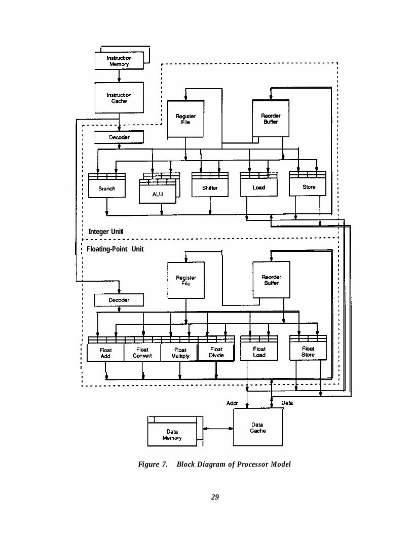
J 1 I
Register ReorderFile Buuer
I
I I I 1
Integer Unit
I [ Floating-Point Unit t I I
1
I Float float noat1I Add convert MultiplyII I
IData
Data * 0 CacheMemory d
,
Figure 7. Block Diagram of Processor Model
29

assigned reorder-buffer location. A subsequent reference to the renamed destination regis-ter obtains the value stored into the reorder buffer or the tag for this value.
The reorder buffer is implemented as a content-addressable memory. It is accessed using aregister number as a key, and returns the latest value written into the register. This organiza-tion performs name mapping and operand access in a single cycle, as does the register file.During instruction decode, the reorder buffer is accessed in parallel with the register file.Then, depending on which one has the most recent value, the desired operand is selected.The operand value-if available-is copied to the reservation station. If the value is notavailable (because it has not been computed yet), the result tag is copied to the reservationstation. This procedure is carriedout for each operand required by each decoded instruction.
If a result register mapped by the reorder buffer is the destination of a previously-decodedinstruction, the previous mapping is marked as invalid, so that subsequent instructions ob-tain the result of the new instruction. At this point, the old register value could be discardedand the reorder-buffer entry freed. However, the entry is preserved in this model because theentry allows the processor to recover the state associated with in-order completion, simplify-ing interrupt and exception handling [Smith and Pleszkun 19851.
When a result becomes available, it is written to the reorder buffer and to any reservation-station entry containing a tag for this result (this requires associative memory in the reserva-tion stations). Subsequent instructions continue to fetch the value from the reorder buffer-unless the entry is superseded by a new value- until the value is retired by writing it to theregister file. Retiring occurs in the order given by sequential execution, preserving the se-quential state for interrupts and exceptions.
The design of the super-scalar pipeline closely parallels the design of a scalar RISC pipeline,to keep the execution rate of sequential instructions as high as their execution rate in a scalarprocessor. Table 2 shows the parallels between the pipeline of the sequential processor andthe pipeline of the super-scalar processor. Table 2 does not show every function performedin the pipeline stages, but does illustrate how the additional functions required by the super-scalar processor fit into the pipeline stages of the sequential processor. In essence, the reor-der buffer augments the register file and operates in parallel with it. The reservation stationsreplace the functional-unit input latches. The distribution of operands and writing of resultsare similar for both processors, except that the super-scalar processor requires more hard-ware, such as buses and write ports.
Loads and stores occur on a single-word interface to a data cache (there are separate busesfor addresses and data). Loads are given priority to use the data-cache interface, since an
30

I
Table 2. Comparisons of Scalar and Super-Scalar Pipelines
Pipeline Stage Scalar Processor Super-Scalar Processor
Fetch fetch one instruction fetch multiple instructions
Decode decode instruction decode instructions
access operand from register file access operands from register fileand reorder buffer
copy operands to functional-unit copy operands to functional-unitinput latches reservation stations
Execute execute instruction execute instructions
arbiirate for result buses
Write-back wriie result to register file write results to reorder buffer
forward results to functional-unit forward results to functional-unitinput latches reservation stations
Result Commit n/a write results to register file
uncompleted load is more likely to stall computation. Stores are buffered to resolve conten-tion with loads over the data-cache interface. A load is issued in program-sequential orderwith respect to other loads, and likewise for a store. Furthermore, a store is issued only afterall previous instructions have completed, to preserve the processor’s sequential state in thedata cache (the store buffer also aids in deferring the issue of stores).
Dependencies between loads and stores are determined by comparing virtual addresses. Forthis study, it is assumed that there is a unique mapping for each virtual page, so that virtual-address comparisons detect all dependencies between the physical memory locations ad-dressed by a process. A load is held because of a store dependency if the load addressmatches the address for a previous store, or if the address of any previous store is not yetvalid. If the valid address of a store matches the address of a load, the load is satisfied di-rectly from the store buffer-once the store data is valid-rather than waiting on the store tocomplete.
3.3.3 Processor Configuration
For the results presented in Section 3.4, the characteristics of the functional units are mod-eled after the R2000 processor and R2010 floating-point unit. Table 3 shows the configura-tion of the functional units. Issue latency is defined as the minimum number of cycles
31

Fundional Unit
Table 3. Configuration of Functional Units
between the issuing of two instructions to a functional unit. Result latency is the number ofcycles taken by the functional unit to generate a result value. Issue and result latencies candepend on whether an operand is a single (32-bit) word or a double-precision (64-bit) float-ing-point number. Table 3 also shows the number of reservation-station entries allocated toeach of the functional units.
The instruction and data caches of both the scalar and the super-scalar processors are 64 kilo-byte (Kbyte), direct-mapped caches with a four-word block size. The instruction and datacaches are loaded via a double-word interface to the main memory; after an initial accesstime of twelve cycles (chosen in light of the anticipated processor operating frequency), theinterface can reload an entire cache block in two cycles. The integer reorder buffer hassixteen entries, the floating-point reorder buffer has eight entries, and the store buffer haseight entries. Both the integer and the floating-point reorder buffers can accept two resultsper cycle, and can retire two results per cycle to the corresponding register file. The integerand floating-point reorder buffers and register files have a sufficient number of read ports tosatisfy all instructions decoded in one cycle.
Again, this processor configuration is intended only as a basis for further study. The hard-ware-and the size of the reservation stations-were determined by experimentation to notlimit performance significantly for the target applications. This processor organization isused as a standard for comparing other hardware alternatives throughout this study.
32

3.4 Results Using an Ideal Instruction Fetcher
Figure 8 shows the performance of the execution hardware described in Section 3.3 on thebenchmark programs. In Figure 8, performance of the three scheduling policies describedin Set tion 2.1.1 is measured in terms of speedup, where speedup is the total number of cyclestaken by the scalar processor to execute a benchmark divided by the total number of cyclestaken by the super-scalar processor for the same benchmark. The results in Figure 8 are ob-tained with ideal instruction fetching. The instruction-fetch unit can supply as many instruc-tions in one cycle as the execution unit can consume, except when there is an instruction-cache miss. The fact that the simulator is trace-driven allows it to supply instructions forscheduling with little regard for branches. Of course, this ability is not available to any realprocessor.
With in-order issue, out-of-order completion yields higher performance than in-order com-pletion. In fact, in-order completion has lower performance than the scalar processor forsome floating-point-intensive benchmarks. Using out-of-order completion, a scalar proces-sor can achieve more instruction concurrency in the presence of high-latency operations
Speedup
in-order out-oforder out-of-ordercompletion completion issuem ~~,q,.&,,‘~.,~,.~~,,; -
I
awk ; Q"lJdless ica3m &hlc QreP
: spi&2g6 : whektol
1
ilIne’ :whf :
Y=
Figure 8. Potential Speedup of Three Scheduling Policies,using Ideal Instruction Fetcher
33

than a super-scalar processor using in-order completion. Still, out-of-order issue consis-tently has the best performance for the benchmark programs.
However, Figure 9 shows that out-of-order issue has much less advantage when the instruc-tion fetcher of the super-scalar processor is modeled after the instruction fetcher of the scalarprocessor (the scalar fetcher, on decoding a branch instruction, waits until the execution ofthe branch before fetching the next sequence of instructions). Figure 9 summarizes the per-formance of the benchmarks with an ideal fetcher and a scalar fetcher, for all three schedul-ing policies. Figure 9 uses the convention-followed throughout the remainder of this the-sis-of showing the low, harmonic mean, and high speedups of all benchmarks. The aver-age speedup with out-of-order issue and an ideal fetcher is 2.4; the speedup decreases to 1.5with a scalar fetcher. For this class of applications and a conventional instruction fetcher, thepenalties incurred for procedural dependencies reduce the processor’s ability to have suffi-cient instructions to schedule concurrently. Unless these penalties can be reduced, out-of-order issue is not cost-effective.
Speedup Ideal Fetcher Scalar Fetcher
compl in compl out issue out
low h-mean high
compl in compl out issue out
Figure 9. Speedups with Ideal Instruction Fetcher andwith Instruction Fetcher Modeled after Scalar Fetcher
34

Chapter 4Instruction Fetching and Decoding
Hardware scheduling is effective only when instructions can be supplied at a sufficient rateto keep the execution unit busy. If the average rate of instruction fetching is less than theaverage rate of instruction execution, performance is limited by instruction fetch. It is easyto provide the required instruction bandwidth for sequential instructions, because the fetchercan simply fetch several instructions per cycle. It is much more difficult to provide instruc-tion bandwidth in the presence of non-sequential fetches caused by branches.
This chapter describes the problems related to instruction fetching in the super-scalar proc-essor, and proposes solutions to these problems. Branch prediction allows a high instruc-tion-fetch rate in the presence of branches, and is key to achieving performance with out-of-order issue. Furthermore, even with branch prediction, performance is highest with a wideinstruction decoder (four instructions wide), because only a wide decoder can provide suffi-cient instruction bandwidth for the execution unit.
4.1 Branches and Instruction-Fetch Ineffkiencies
Branches reduce the ability of the processor to fetch instructions because they make instruc-tion fetching dependent on the results of instruction execution. When the outcome of abranch is not known, the instruction fetcher is stalled or may be fetching incorrect instruc-tions, depleting the instruction window of instructions and reducing the chances that theprocessor can find instructions to execute concurrently. This effect is similar to the effect ofa branch on a scalar processor, except that the penalty is greater in a super-scalar processorbecause it is attempting to fetch and execute more than one instruction per cycle.
But branches also affect the execution rate in another way that is unique to the super-scalarprocessor. Branches disrupt the sequentiality of instruction addressing, causing instructionsto be misaligned with respect to the instruction decoder. This misalignment in turn causessome otherwise valid fetch and decode cycles to be only partially effective in supplying theprocessor with instructions, because the entire width of the decoder is not occupied by validinstructions.
The sequentially-fetched instructions between branches are called a run, and the number ofinstructions fetched sequentially is called the run length. Figure 10 shows two instructionruns occupying four instruction-cache blocks (a four-word cache block is assumed here for
35

BranchcI
Tl T2 T3 Target Cache Block #l- - - Target Cache Bbck #2
-
T4
Figure IO. Sequence of Two Instruction Runs for IllustratingDecoder Behavior
the purposes of illustration). The fist run consists of instructions SlS5, which contain abranch to the second run consisting of instructions Tl-T4. Figure 11 shows how these in-struction runs are sequenced through straightforward four-instruction and two-instructiondecoders assuming-for illustration-that two cycles are required to determine the outcomeof a branch.
The four-instruction decoder provides higher instruction bandwidth in this example-l. 125instructions per cycle, compared to 0.9 instructions per cycle for the two-instruction de-coder-but neither decoder provides adequate bandwidth to exploit the available instruction
Four-lnstnrction Decoder Branch Two-Instruction DecoderDelay
I
1 .125 instructions/cycle
0.9 instructions/cycle
Figure I I. Sequence of Instructions in Figure 10 Through Two-Instructionand Four-Instruction Decoders
36
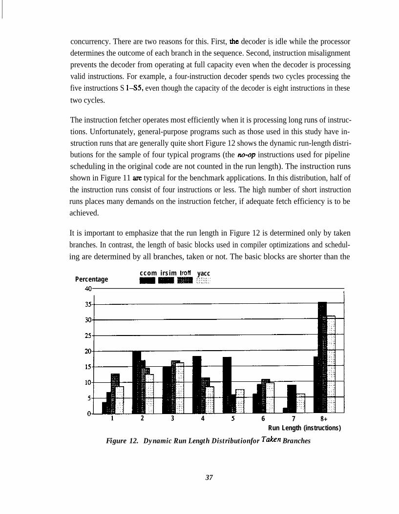
concurrency. There are two reasons for this. First, the decoder is idle while the processordetermines the outcome of each branch in the sequence. Second, instruction misalignmentprevents the decoder from operating at full capacity even when the decoder is processingvalid instructions. For example, a four-instruction decoder spends two cycles processing thefive instructions S lS5, even though the capacity of the decoder is eight instructions in thesetwo cycles.
The instruction fetcher operates most efficiently when it is processing long runs of instruc-tions. Unfortunately, general-purpose programs such as those used in this study have in-struction runs that are generally quite short Figure 12 shows the dynamic run-length distri-butions for the sample of four typical programs (the no-op instructions used for pipelinescheduling in the original code are not counted in the run length). The instruction runsshown in Figure 11 ate typical for the benchmark applications. In this distribution, half ofthe instruction runs consist of four instructions or less. The high number of short instructionruns places many demands on the instruction fetcher, if adequate fetch efficiency is to beachieved.
It is important to emphasize that the run length in Figure 12 is determined only by takenbranches. In contrast, the length of basic blocks used in compiler optimizations and schedul-ing are determined by all branches, taken or not. The basic blocks are shorter than the
Percentage40
ccom irsim troff yacc
1
1 2 3 4 5 6 7 8+Run Length (instructions)
Figure 12. Dynamic Run Length Distributionfor Taken Branches
37
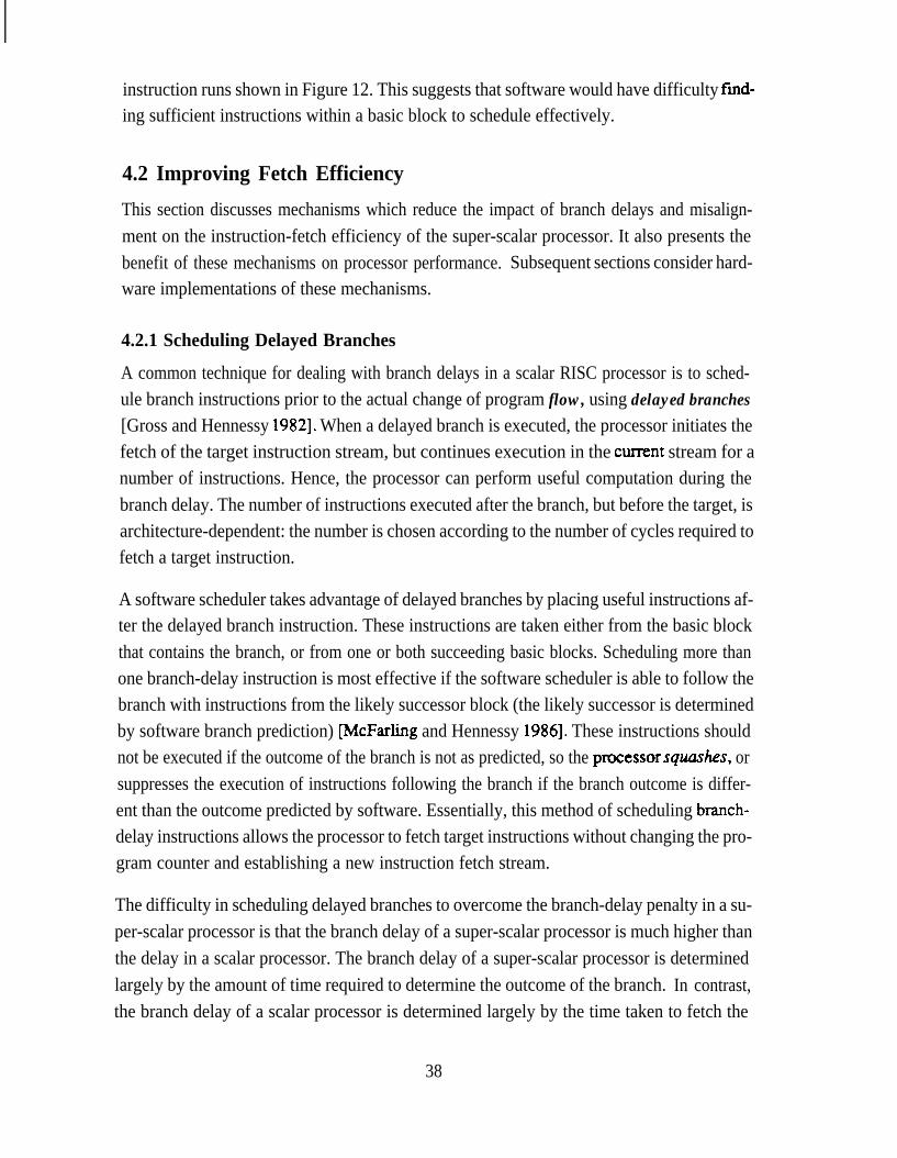
instruction runs shown in Figure 12. This suggests that software would have difficulty fmd-ing sufficient instructions within a basic block to schedule effectively.
4.2 Improving Fetch Efficiency
This section discusses mechanisms which reduce the impact of branch delays and misalign-ment on the instruction-fetch efficiency of the super-scalar processor. It also presents thebenefit of these mechanisms on processor performance. Subsequent sections consider hard-ware implementations of these mechanisms.
4.2.1 Scheduling Delayed Branches
A common technique for dealing with branch delays in a scalar RISC processor is to sched-ule branch instructions prior to the actual change of program flow, using delayed branches[Gross and Hennessy 19821. When a delayed branch is executed, the processor initiates thefetch of the target instruction stream, but continues execution in the current stream for anumber of instructions. Hence, the processor can perform useful computation during thebranch delay. The number of instructions executed after the branch, but before the target, isarchitecture-dependent: the number is chosen according to the number of cycles required tofetch a target instruction.
A software scheduler takes advantage of delayed branches by placing useful instructions af-ter the delayed branch instruction. These instructions are taken either from the basic blockthat contains the branch, or from one or both succeeding basic blocks. Scheduling more thanone branch-delay instruction is most effective if the software scheduler is able to follow thebranch with instructions from the likely successor block (the likely successor is determinedby software branch prediction) lJ%zFarling and Hennessy 19861. These instructions shouldnot be executed if the outcome of the branch is not as predicted, so the ptocessorsquarhes, orsuppresses the execution of instructions following the branch if the branch outcome is differ-ent than the outcome predicted by software. Essentially, this method of scheduling branch-delay instructions allows the processor to fetch target instructions without changing the pro-gram counter and establishing a new instruction fetch stream.
The difficulty in scheduling delayed branches to overcome the branch-delay penalty in a su-per-scalar processor is that the branch delay of a super-scalar processor is much higher thanthe delay in a scalar processor. The branch delay of a super-scalar processor is determinedlargely by the amount of time required to determine the outcome of the branch. In contrast,the branch delay of a scalar processor is determined largely by the time taken to fetch the
38

target instruction. In a super-scalar processor with out-of-order execution, the number ofcycles of branch delay can be quite high. Also, because the super-scalar processor fetchesmore than one instruction per cycle, a very large number of instructions must be scheduledafter the branch to overcome the penalty of the branch &lay.
Figure 13 plots extremes in the average number of branch-delay cycles (that is, the averagenumber of cycles between the time that a predicted branch instruction is decoded and thetime that the outcome is determined) as a function of speedup. Figure 13 also shows theextremes of instruction-fetch bandwidth sustained during this time interval. The range ofspeedups was obtained by varying machine configurations and instruction-fetch mecha-nisms over all of the sample benchmarks.
Figure 13 illustrates that the branch delay increases significantly as processor speedup in-creases. The increase of the branch delay with increasing speedup is the result of the buffer-ing provided by the instruction window. With larger speedups, the instruction window iskept relatively fuller than with smaller speedups. A full window, and the dependencies a fullwindow implies, prevent the resolution of branches for several cycles. Furthermore, duringthese cycles, the processor must sustain an instruction fetch rate of more than one instructionper cycle. Thus, for example, to sustain a speedup of two, software would have to scheduleabout eight instructions following a branch (four cycles of delay at two instructions per
Delay & Bandwidth(Cycle: & Instructions/Cycle)
iSpeedup
Figure 13. Branch Delay and Penalty Versus Speedy,
39

cycle): Pleszkun et al. [ 19871 demonstrate the difficulties in scheduling such a high numberof instructions after a branch.
4.2.2 Branch PredictionThe instruction-fetch delays caused by branches can be reduced by predicting the outcomeof the branch during instruction fetch, without waiting for the execution unit to indicatewhether or not the branch should be taken. Figure 14 illustrates how this helps for the in-struction sequence of Figure 11. Branch prediction relies on the fact that the future outcomeof a branch can usually be predicted using knowledge of previous branch outcomes. Hard-ware branch prediction predicts branches dynamically using a structure such as a branchtarget buffer [Lee and Smith 19841, and relies on the fact that the outcome of a branch isstable over time. Software branchprediction predicts branches statically using an executionprofile (or reasonable guess based on program context) to annotate the program with predic-tion information, and relies on the fact the outcome of a branch is usually the same.
Though they rely on different branch properties, software and hardware branch predictionyield comparable prediction accuracies [McFarling and Hennessy 1986, Ditzel and McLel-lan 19871. It is important, though, that the branch-prediction algorithm not incur any delaycycles to determine the predicted branch outcome; Figure 15 illustrates the effect on fetchefficiency if a cycle is required to determine the predicted branch outcome. Any unusedcycles between instruction runs cause a large reduction in fetch efficiency, because instruc-tion runs are generally short. Hardware branch prediction has some advantage over softwareprediction in that it easily avoids this additional cycle. Software prediction requires an addi-tional cycle for decoding the prediction information and computing the target address, un-less the instruction format explicitly describes branches predicted to be taken (for example,
Four-Instruction Decoder Branch Two-Instruction DecoderDelay
Re vedT
--i
T4 I - I - -1
2.25 instructions/cycle
i--
-- SlSl
s 2s 2 s 3s 3
s 4s 4 s 5s 5mm
-- TlTl
T2T2 T3T3
T4T4 --
1.5 instructions/cycle
Figure 14. Sequence of Instructions in Figure II Through Two-Instructionand Four-Instruction Decoders with Branch Prediction
40
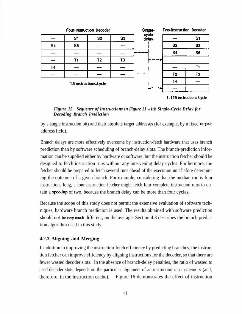
Four-lnstnxtion Decoder Single- Two-Instruction Decoder
-
T4-
Tl T2- -
- -
1.5 instructions/cycle
T3 /--
- I- --
4
IL - -
1 .125 instructions/cycle
Figure 15. Sequence of Instructions in Figure 11 with Single-Cycle Delay forDecoding Branch Prediction
by a single instruction bit) and their absolute target addresses (for example, by a fixed target-address field).
Branch delays are more effectively overcome by instruction-fetch hardware that uses branchprediction than by software scheduling of branch-delay slots. The branch-prediction infor-mation can be supplied either by hardware or software, but the instruction fetcher should bedesigned to fetch instruction runs without any intervening delay cycles. Furthermore, thefetcher should be prepared to fetch several runs ahead of the execution unit before determin-ing the outcome of a given branch. For example, considering that the median run is fourinstructions long, a four-instruction fetcher might fetch four complete instruction runs to ob-tain a speedup of two, because the branch delay can be more than four cycles.
Because the scope of this study does not permit the extensive evaluation of software tech-niques, hardware branch prediction is used. The results obtained with software predictionshould not be very much different, on the average. Section 4.3 describes the branch predic-tion algorithm used in this study.
4.2.3 Aligning and Merging
In addition to improving the instruction-fetch efficiency by predicting branches, the instruc-tion fetcher can improve efficiency by aligning instructions for the decoder, so that there arefewer wasted decoder slots. In the absence of branch-delay penalties, the ratio of wasted toused decoder slots depends on the particular alignment of an instruction run in memory (and,therefore, in the instruction cache). Figure 16 demonstrates the effect of instruction
41
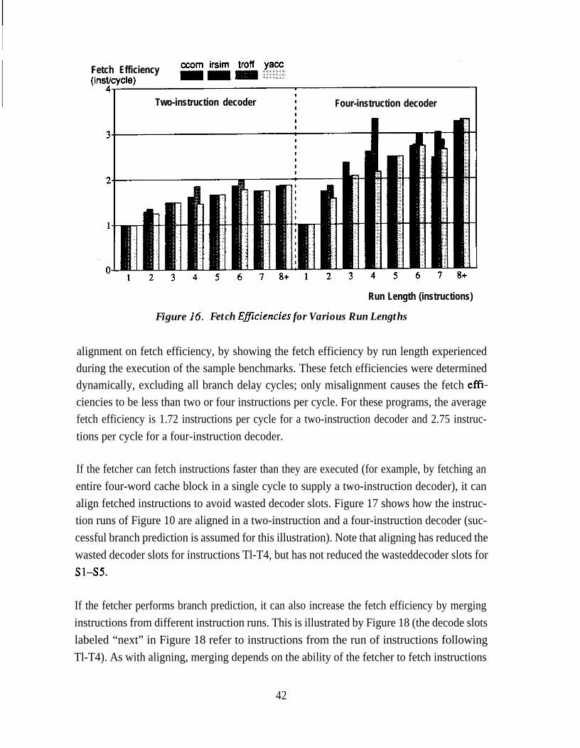
Fetch Efficiency‘cycle)
Two-instruction decoder Four-instruction decoder
Run Length (instructions)
Figure 16. Fetch Eficiencies for Various Run Lengths
alignment on fetch efficiency, by showing the fetch efficiency by run length experiencedduring the execution of the sample benchmarks. These fetch efficiencies were determineddynamically, excluding all branch delay cycles; only misalignment causes the fetch efft-ciencies to be less than two or four instructions per cycle. For these programs, the averagefetch efficiency is 1.72 instructions per cycle for a two-instruction decoder and 2.75 instruc-tions per cycle for a four-instruction decoder.
If the fetcher can fetch instructions faster than they are executed (for example, by fetching anentire four-word cache block in a single cycle to supply a two-instruction decoder), it canalign fetched instructions to avoid wasted decoder slots. Figure 17 shows how the instruc-tion runs of Figure 10 are aligned in a two-instruction and a four-instruction decoder (suc-cessful branch prediction is assumed for this illustration). Note that aligning has reduced thewasted decoder slots for instructions Tl-T4, but has not reduced the wasteddecoder slots forSlS5.
If the fetcher performs branch prediction, it can also increase the fetch efficiency by merginginstructions from different instruction runs. This is illustrated by Figure 18 (the decode slotslabeled “next” in Figure 18 refer to instructions from the run of instructions followingTl-T4). As with aligning, merging depends on the ability of the fetcher to fetch instructions
42
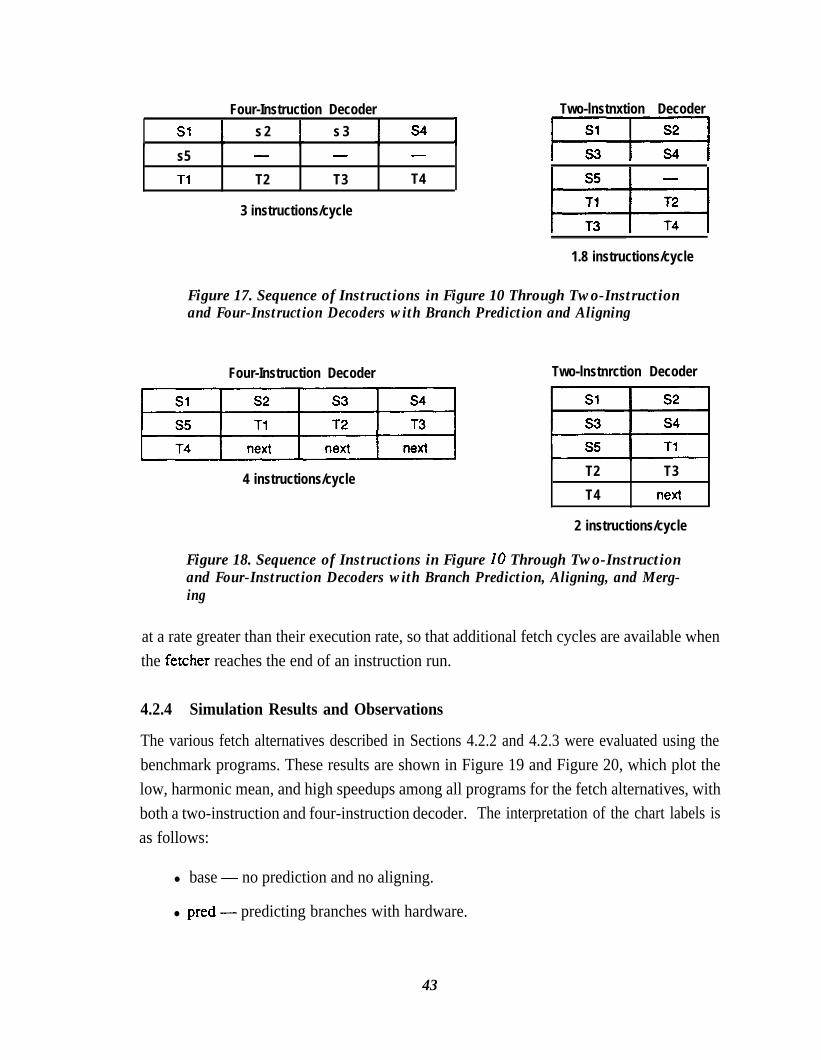
SlFour-Instruction Decoder
s 2 s 3 s4I
s5 - - -
Tl T2 T3 T4
3 instructions/cycle
Two-lnstnxtion Decoder
m%l
1.8 instructions/cycle
Figure 17. Sequence of Instructions in Figure 10 Through Two-Instructionand Four-Instruction Decoders with Branch Prediction and Aligning
Four-Instruction Decoder Two-lnstnrction Decoder
4 instructions/cycle T2 T3
T4 next
2 instructions/cycle
Figure 18. Sequence of Instructions in Figure 10 Through Two-Instructionand Four-Instruction Decoders with Branch Prediction, Aligning, and Merg-ing
at a rate greater than their execution rate, so that additional fetch cycles are available whenthe fetcher reaches the end of an instruction run.
4.2.4 Simulation Results and Observations
The various fetch alternatives described in Sections 4.2.2 and 4.2.3 were evaluated using thebenchmark programs. These results are shown in Figure 19 and Figure 20, which plot thelow, harmonic mean, and high speedups among all programs for the fetch alternatives, withboth a two-instruction and four-instruction decoder. The interpretation of the chart labels isas follows:
l base - no prediction and no aligning.
l pred- predicting branches with hardware.
43

Speedup
3
0base Pd a&P merge perfect max
Figure 19. Speedups of Fetch Alternatives with Two-Instruction Decoder
Speedup
base merge perfect max
Figure 20. Speedups of Fetch Alternatives with Four-Instruction Decoder
44

l align - aligning the beginning of instruction runs in the decoder when possi-ble.
l merge - merging instructions from different runs when possible.
l perfect - perfect branch prediction, but with alignment penalties. This caseis included for comparison.
l ma X- the maximum speedup allowed by the execution hardware, with nofetch limitations. This case is included for comparison.
The speedups for alI but the final two sets of results are cumulative: the speedups for a givencase includes the benefit of all previous cases. Aligning and merging are performed onlywhen the fetcher has sufficient cycles to perform these operations.
-l-he principle observation from these results is that branch prediction yields the greatest in-cremental benefit of any of the mechanisms for improving fetch efficiency. Section 4.3 dis-cusses a hardware implementation of branch prediction that incurs a small relative hardwarecost.
Figure 19 and Figure 20 also show that a four-instruction decoder always out-performs atwo-instruction decoder. This is not surprising, because the four-instruction decoder hastwice the potential instruction bandwidth of the two-instruction decoder. None of the tech-niques applied to a two-instruction decoder to overcome this limitatiorr-such as aligningand merging-yield the same advantage as a four-instruction decoder. The essential prob-lem with a two-instruction decoder is that the instruction throughput can never exceed twoinstructions per cycle-the fetch efficiency is always below this limit. However, a two-in-struction decoder places fewer demands on hardware than a four-instruction decoder, par-ticularly for read ports on the register file. Section 4.4 considers the implementation of afour-instruction decoder that has reduced hardware demands.
There is some advantage in aligning and merging instruction runs, but these do not seem tobe appropriate functions for hardware, because they increase the length of the critical delaypath between the instruction cache and the decoder. A more efficient method to align andmerge instruction runs relies on software. Software can align instructions by unrolling loopsand by arranging instructions on appropriate memory boundaries. Furthermore softwarecan merge instruction runs using software branch-prediction. If the software scheduler caneffectively predict the outcome of a branch, it can move instructions from the likely succes-sor basic block to pad the remainder of the decode slots following the branch (these instruc-tion are decoded at the same time as the branch). Note that this is similar to scheduling
45

branch &lays in a scalar processor, but the goal is to improve the effkiency of the decoder.The padded instructions are executed if the prediction is correct, and are squashed if the pm-diction is not correct. The reorder buffer (or similar structure) in the execution unit can eas-ily nullify a variable number of instructions following a branch, depending on the alignmentand outcome of the branch.
Software aligning and merging has the advantage that instruction runs are always aligned,and are merged when a branch is successfully predicted- This is in contrast to hardware,which can perform these functions only with reserve fetch bandwidth and alignment hard-ware in the critical delay path between the instruction cache and decoder.
4.3 Implementing Hardware Branch PredictionA conventional method for hardware branch-prediction uses a branch target buffer [Lee andSmith 19841 to collect information about the most-recently executed branches. Typically,the branch target buffer is accessed using an instruction address, and indicates whether ornot the instruction at that address is a branch instruction. If the instruction is a branch, thebranch target buffer indicates the predicted outcome and the target address. Figure 21shows the average hits rates of a branch target buffer on the sample benchmark programs.Figure 21 is included only as an illustration: the indicated branch-prediction effectiveness
Hit Rate%lOO-
90”
16 32 64 128 256 512 1048 2048
Number of Entries
Figure 21. Average Branch Target Bu@er Hit Rates
46

agrees with the results reported by others [Lee and Smith 1984, McFarling and Hennessy1986, Ditzel and McLellan 19871. A large branch target buffer is required to achieve a goodhit ratio, because, unlike a cache, there is one entry per address tag and the branch targetbuffer cannot take advantage of spatial locality. However, the hit ratio of even a large branchtarget buffer is still rather low, due to n&prediction.
A better hardware alternative to a branch target buffer is to include branch-prediction infor-mation in the instruction cache. Each instruction cache block includes additional fields thatindicate the address of the block’s successor and information indicating the location of abranch in the block. When the instruction fetch obtains a cache block containing correctinformation, it can easily fetch the next cache block without waiting on the decoder or exe-cution unit to indicate the proper fetch action to be taken. This is comparable to a branch‘target buffer with a number of entries equal to the number of blocks in the instruction cacheand with associativity equal to the associativity of the instruction cache. This scheme isnearly identical to the branch target buffer in prediction accuracy (most benchmark pro-g-rams experienced a branch prediction accuracy of 80-95% in this study).
Indirect branches (that is, branches whose target addresses are specified by the contents ofregisters) can reduce the branch prediction ratio even when they are unconditional, becausebranch-prediction hardware cannot always predict the successor cache block when the tar-get address can change during execution. However, the target addresses of most dynamicindirect branches show locality because of repetitive procedure calls from the same proce-dure, making it useful to predict such branches if the cost is not high (the benefit is about a2-3% improvement in branch-prediction accuracy).
The results given in Section 4.2.4 assume the existence of an instruction fetcher that canfetch instructions without any delay for successfully-predicted branches. ‘l-his section dis-cusses the implementation of this instruction fetcher to demonstrate that an implementationis feasible and to show that it causes only a small increase in the size of the instruction cache.Also, this section shows that the fetcher can predict indirect branches with no additional costover that required for the basic implementation.
4.3.1 Basic Organization
Figure 22 shows a sample organization for the instruction-cache entry required by the in-struction fetcher (this entry may include other information not important for this discussion).For this example, the cache entry holds four instructions. The entry also contains instruc-tion-fetch information which is shown expanded in Figure 22. The fetch information
47

Cache Entry
Fetch Info
\\
\\
Address tag I
Successor index I
Branch block index
Figure 22. Instruction Cache Entry for Branch Prediction
contains an address tag (used in the normal fashion) and two additional fields used by theinstruction fetcher:
l The successor index field indicates both the next entry predicted to befetched and the frost instruction within this next entry predicted to be exe-cuted. The successor index does not specify a full instruction address, but isof sufficient size to select any instruction within the cache. For example, a 64Kbyte, direct-mapped cache requires a 16bit successor index if all instruc-tions are 32 bits in length.
l The branch block index field indicates the location of a branch point withinthe instruction block. Instructions beyond the branch point are predicted notto be executed- Figure 23 shows sample instruction-cache entries for thecode sequence of Figure 14, assuming a 64Kbyte, direct-mapped cache andwith the indicated instruction addresses.
4.3.2 Setting and Interpreting Cache Entries
When a cache entry is first loaded, the cache fetch hardware sets the address tag in the nor-mal manner, and sets the successor index field to the next sequential fetch address. The de-fault for a newly-loaded entry, therefore, is to predict that branches are not taken. If the pre-diction is incorrect, this will be discovered later by the normal procedure for detecting amispredicted branch.
As Figure 23 illustrates, a target program counter can be constructed at branch points byconcatenating the successor index field of the branching entry to the address tag of the
48
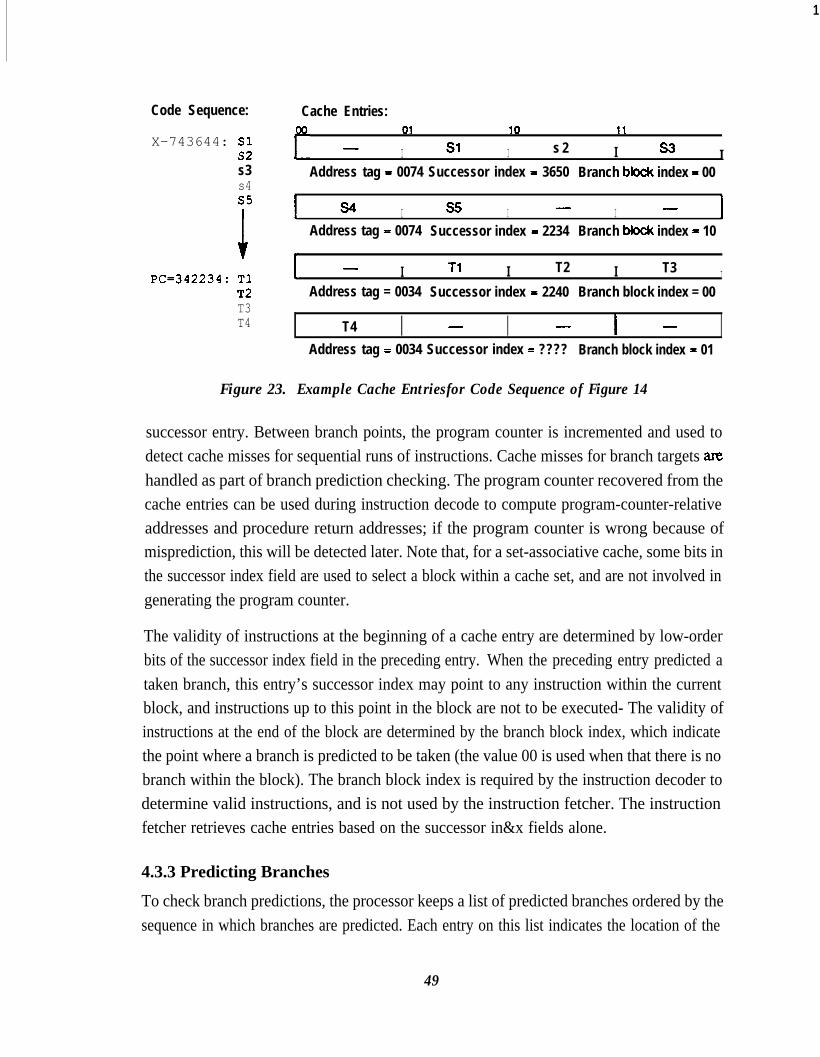
1
Code Sequence: Cache Entries:01 10 11
X-743644: Sl -s2 I Sl I s 2 I s3 Is3 Address tag = 0074 Successor index = 3650 Branch bktck index = 00s4s5
1 ;
s4 I s5 I - I -I
Address tag = 0074 Successor index - 2234 Branch bbck index - 10
X=342234: TlT2T3T4
- I Tl I T2 I T3 IAddress tag = 0034 Successor index = 2240 Branch block index = 00
T4 I - I - I - IAddress tag = 0034 Successor index = ???? Branch block index = 01
Figure 23. Example Cache Entriesfor Code Sequence of Figure 14
successor entry. Between branch points, the program counter is incremented and used todetect cache misses for sequential runs of instructions. Cache misses for branch targets amhandled as part of branch prediction checking. The program counter recovered from thecache entries can be used during instruction decode to compute program-counter-relativeaddresses and procedure return addresses; if the program counter is wrong because ofmisprediction, this will be detected later. Note that, for a set-associative cache, some bits inthe successor index field are used to select a block within a cache set, and are not involved ingenerating the program counter.
The validity of instructions at the beginning of a cache entry are determined by low-orderbits of the successor index field in the preceding entry. When the preceding entry predicted ataken branch, this entry’s successor index may point to any instruction within the currentblock, and instructions up to this point in the block are not to be executed- The validity ofinstructions at the end of the block are determined by the branch block index, which indicatethe point where a branch is predicted to be taken (the value 00 is used when that there is nobranch within the block). The branch block index is required by the instruction decoder todetermine valid instructions, and is not used by the instruction fetcher. The instructionfetcher retrieves cache entries based on the successor in&x fields alone.
4.3.3 Predicting Branches
To check branch predictions, the processor keeps a list of predicted branches ordered by thesequence in which branches are predicted. Each entry on this list indicates the location of the
49

branch in the cache; this location is identified by concatenating the successor index of theentry preceding the branching entry with the branch block index. Each entry also contains acomplete program-counter value for the target of the branch. Note that because the cacheonly predicts taken branches this list only contains taken branches.
The processor executes all branches in their original program sequence (this is guaranteedby the operation of the branch reservation station). Note that these branches are detected byinstruction decoding, independent of prediction information maintained by the instructionfetcher. When a branch is executed, the processor compares information related to thisbranch with the information at the head of the list of predicted branches. The following con-ditions must hold for a successful prediction:
l If the branch is taken, its location in the cache must match the location of thenext branch on the list of predictions. -l-his is required to detect a takenbranch that was predicted to be not taken.
l The predicted target address of the branch at the head of the list must matchthe next instruction address determined by executing the branch. This com-parison is relevant only if the location of the branch matches the location ofthe next branch on the list of predictions, and is required primarily to detect anon-taken branch that was predicted to be taken. However, since the pre-dicted target address is based on the address tag of the successor block, thiscomparison also detects that cache replacement has removed the original tar-get entry. In addition, comparing target addresses checks that indirectbranches were properly predicted.
If either or both of the above conditions does not hold, the instruction fetcher hasmispredicted a branch. The instruction fetcher uses the location of the branch determined bythe execution unit to update the appropriate cache entry.
4.3.4 Hardware and Performance Costs
The principal hardware cost of the proposed branch-prediction scheme is the increase in thecache size caused by the successor index and branch block index fields in each entry. For a64 Kbyte, direct-mapped cache, these add about 11% to the cache storage required. How-ever, the performance increase obtained by branch prediction seems worth this cost, espe-cially considering the normal size/performance tradeoffs involved in cache design[Przybylski et al. 19881.
This scheme retains branch history only to the extent of tracking the most recent takenbranches. Branch-prediction accuracy can be increased by retaining more branch-history
50
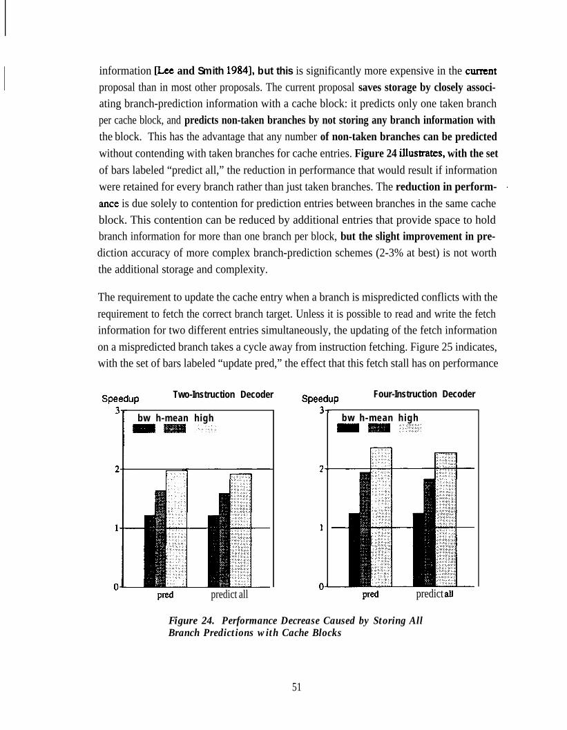
information [Lee and Smith 19841, but this is significantly more expensive in the cunentproposal than in most other proposals. The current proposal saves storage by closely associ-ating branch-prediction information with a cache block: it predicts only one taken branchper cache block, and predicts non-taken branches by not storing any branch information withthe block. This has the advantage that any number of non-taken branches can be predictedwithout contending with taken branches for cache entries. Figure 24 ilIustrates, with the setof bars labeled “predict all,” the reduction in performance that would result if informationwere retained for every branch rather than just taken branches. The reduction in perform- Iante is due solely to contention for prediction entries between branches in the same cacheblock. This contention can be reduced by additional entries that provide space to holdbranch information for more than one branch per block, but the slight improvement in pre-diction accuracy of more complex branch-prediction schemes (2-3% at best) is not worththe additional storage and complexity.
The requirement to update the cache entry when a branch is mispredicted conflicts with therequirement to fetch the correct branch target. Unless it is possible to read and write the fetchinformation for two different entries simultaneously, the updating of the fetch informationon a mispredicted branch takes a cycle away from instruction fetching. Figure 25 indicates,with the set of bars labeled “update pred,” the effect that this fetch stall has on performance
Speedup Two-Instruction Decoder Speedup Four-Instruction Decoder
bw h-mean high
predict all
I-
,__
P-
bw h-mean high
predict all
Figure 24. Performance Decrease Caused by Storing AllBranch Predictions with Cache Blocks
51

WeduP Two-Instruction Decoder Four-Instruction DecoderI-
),-
l-
bw h-mean highm - +.;I::;,;:i;..:.:.:...
Figure 25. Performance Degradation with Single-Port Cache Tags
for a two-instruction and a four-instruction decoder. For comparison, the results of the“pred” case from Figure 20 is repeated in Figure 25. The additional fetch stall causes only asmall reduction in performance: 3% with a two-instruction decoder and 4% with a four-in-struction decoder. -l-his is reasonable, since the penalty for a mispredicted branch is high(see Figure 13), but is incurred infrequently; the additional cycle represents only a smallproportional increase in the penalty.
4.4 Implementing a Four-Instruction Decoder
Section 4.2.4 showed that a four-instruction decoder yields higher performance (20-25%higher) than a two-instruction decoder, because it is less sensitive to instruction alignmentthan the two-instruction decoder. However, directly modeling a four-instruction decoderafter a single-instruction decoder is not cost-effective. In a straightforward implementation,decoding four instructions per cycle requires eight read ports on both the register file and thereorder buffer, and eight buses for distributing operands. Furthermore, with this four-in-struction decoder, the execution hardware described in Section 3.3 requires a total of 210comparators for dependency analysis (192 in the result buffer and 18 to check dependenciesbetween decoded instructions). At the same time, the performance benefit is limited by in-struction fetching and dependencies. Doubling the amount of hardware over a two-
52
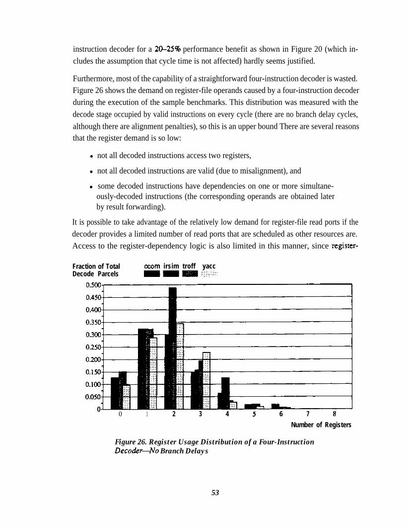
instruction decoder for a 20-25% performance benefit as shown in Figure 20 (which in-cludes the assumption that cycle time is not affected) hardly seems justified.
Furthermore, most of the capability of a straightforward four-instruction decoder is wasted.Figure 26 shows the demand on register-file operands caused by a four-instruction decoderduring the execution of the sample benchmarks. This distribution was measured with thedecode stage occupied by valid instructions on every cycle (there are no branch delay cycles,although there are alignment penalties), so this is an upper bound There are several reasonsthat the register demand is so low:
l not all decoded instructions access two registers,
l not all decoded instructions are valid (due to misalignment), and
l some decoded instructions have dependencies on one or more simultane-ously-decoded instructions (the corresponding operands are obtained laterby result forwarding).
It is possible to take advantage of the relatively low demand for register-file read ports if thedecoder provides a limited number of read ports that are scheduled as other resources are.Access to the register-dependency logic is also limited in this manner, since register-
Fraction of TotalDecode Parcels
axm irsim troff yacc
0 1 2 3 4 6 7 aNumber of Registers
Figure 26. Register Usage Distribution of a Four-InstructionDecockr4o Branch Delays
53

dependency logic is closely associated with register access. Figure 27 shows the results ofconstraining the number of registers available to a four-instruction decoder. This constraintreduces performance by less than 2%.
As will be shown in this section, arbitration for register-file read ports is difficult ifit is per-formed by hardware alone. However, it is conceptually easy for a software scheduler toknow which instructions will be decoded simultaneously and to group instructions so thatregister demands are limited for each group of instructions. Software can also facilitate thedetection of register dependencies between simultaneously-decoded instructions.
4.4.1 Implementing a Hardware Register-Port Arbiter
Arbitrating for register-file ports requires that the decoder implement a prioritized select ofthe register identifiers to be applied to the register file. The register file is typicalIy accessedduring the second half of the decode cycle, so the register identifiers must be valid at theregister file by the mid-point of the decode cycle. For this reason, the prioritized register-identifier selection must be accomplished within about half of the processor cycle.
It is easy to design the instruction encoding so that register requirements are known early inthe decode cycle. However, it is difficult to arbitrate register access among contending in-structions. Table 4 shows an estimate of the amount of logic required to implement the
bw h-mean high.‘..
Figure 27. Performance Degradation Caused by Limiting aFour-Instruction Deco&r to Four Register-File Ports
54

Table 4. Estimate of Register-Port Arbiter Size: Two Logic Levels
Note: the first of each table entry is the number of gates required in the first level of logic, and thesecond is the number of inputs required by each gate. The size of the gates in the second logiclevel are indicated by the total number of gates in the first level.
prioritized register-identifier selection in two levels of logic. The eight register operandspossibly required by a four-instruction decoder are shown across the top of Table 4. Eachrow of the Table 4 shows, for each possible register operand, the number of gates and thenumber of inputs of each gate required to generate an enable signal. This signal selects thegiven register identifier at one input of an eight-to-one multiplexer, enabling the given oper-and to be accessed at the indicated register-file port. This logic follows the following gen-eral form:
l if the fust register operand requires a register access, it is always enabled onthe first port.
l if the second register operand requires a register access, it is enabled on thefmt port if the first register operand does not require an access, and is other-wise enabled on the second port.
l in general, the register identifier for a required access is enabled on the firstport if no other previous operand requires an access, on the second port if oneprevious operand requires an access, on the third port if two previous oper-ands use ports, on the fourth port if three previous operands use ports, and onno port (and the decoder stalls) if four previous operands use ports.
This type of arbitration occurs frequently in the super-scalar processor, to resolve contentionfor shared resources. Resolving contention within two logic levels requires or&r(md)gates where m is the number of resources being contended for (in this case, four register-fileread ports) and n is the number of contenders (in this case, eight register-operand identifi-ers). A factor mn results from generation of an enable per contender per resource, and afactor of n2 results from interaction between contenders. Since the largest first-level gate
55
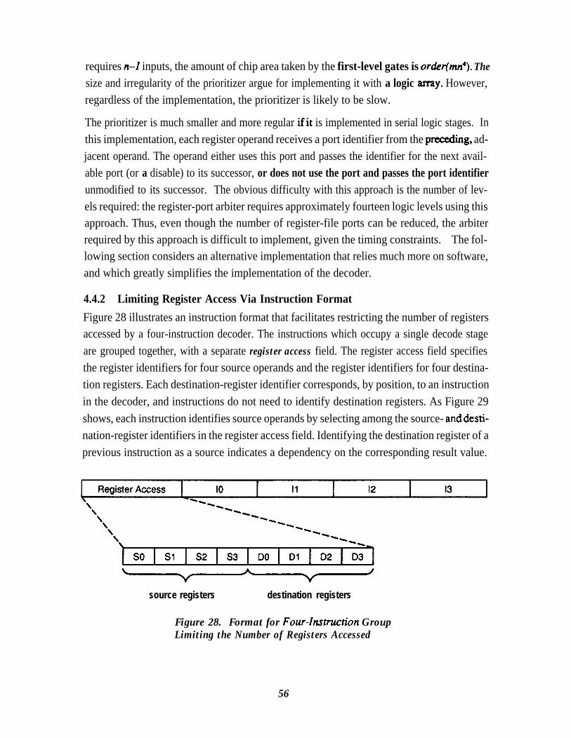
requires n-l inputs, the amount of chip area taken by the first-level gates is order(mr+). Thesize and irregularity of the prioritizer argue for implementing it with a logic anay. However,regardless of the implementation, the prioritizer is likely to be slow.
The prioritizer is much smaller and more regular ifit is implemented in serial logic stages. Inthis implementation, each register operand receives a port identifier from the pmceding, ad-jacent operand. The operand either uses this port and passes the identifier for the next avail-able port (or a disable) to its successor, or does not use the port and passes the port identifierunmodified to its successor. The obvious difficulty with this approach is the number of lev-els required: the register-port arbiter requires approximately fourteen logic levels using thisapproach. Thus, even though the number of register-file ports can be reduced, the arbiterrequired by this approach is difficult to implement, given the timing constraints. The fol-lowing section considers an alternative implementation that relies much more on software,and which greatly simplifies the implementation of the decoder.
4.4.2 Limiting Register Access Via Instruction FormatFigure 28 illustrates an instruction format that facilitates restricting the number of registersaccessed by a four-instruction decoder. The instructions which occupy a single decode stageare grouped together, with a separate register access field. The register access field specifiesthe register identifiers for four source operands and the register identifiers for four destina-tion registers. Each destination-register identifier corresponds, by position, to an instructionin the decoder, and instructions do not need to identify destination registers. As Figure 29shows, each instruction identifies source operands by selecting among the source- anddesti-nation-register identifiers in the register access field. Identifying the destination register of aprevious instruction as a source indicates a dependency on the corresponding result value.
source registers destination registers
Figure 28. Format for Four-Insnrction GroupLimiting the Number of Registers Accessed
56

R e g i s t e r A c c e s s lo I1 12 I3
Figure 29. &le Operand Encoding using Instruction Format of Figure 28
For example, in Figure 29, the second instruction depends on the result of the fast instruc-tion, because the field DO specif?cs a source operand of the second instruction.
With this approach, the decoder is easily implemented. The source-register identifiers in theregister access field are applied to the register file, and each instruction simply selects oper-ands from among the accessed operands. The decoder cannot stall because too many regis-ters are required (software has inserted no-ops for this purpose, as explained below).
This approach has one drawback compared to the hardware approach described in Section4.4.1. It does not allow register usage to be reduced because of instruction misalignment.Software cannot know about dynamic branch activity, and must assume that all decode slotsare fully occupied. However, this approach has an advantage over that of Section 4.4.1 inthat it allows several instructions within the group to access the same operand register with-out using additional register-file ports. This sharing is difficult to accomplish in hardware,requiring 28 comparators for detecting matching source-register identifiers and complicat-ing register-port arbitration to allow register-port sharing for common identifiers.
To take advantage of this instruction format, the compiler or a post-processor groups in-structions by decoder boundaries, and arranges the register usage of these instructions sothat the group of instructions accesses no more than four total register operands. Meetingthis restriction may require the insertion of no-op instructions into the group. Havingbranches appear within the group does not cause any difficulties: whether or not the branchis taken during execution, the instructions following the branch can indicate as source oper-ands the destination registers of instructions preceding the branch.
However, branch targets within the instruction group interfere with the goal of statically en-coding instruction dependencies. If an instruction in the group is the target of a branch, theinstructions preceding the target may or may not be executed, depending on the path of exe-cution through the block. Thus, an instruction following the target cannot statically indicatea dependency on an instruction preceding the target: the dependency may or may not existwithin the group, depending on the execution path. There are several possible solutions tothis problem:
57

l Software can avoid indicating dependencies between instructions whichhave an intervening branch target, and simply use a separate source-registerfield for the dependent instruction. In this case, hardware must be able todetect whether or not a dependency exists during instruction decode. Theinstruction format loses the advantage of indicating dependencies, but stiIlretains the advantage of reducing register-port requirements.
l Hardware can rearrange register identifiers within the instruction dependingon the path of execution. For example, destination-register identifiers of un-executed instructions preceding a branch target can be moved to correspond-ing source-register fields; instructions that refer to these fields are alsochanged to reflect the moved identifier. Figure 30 shows how the hardwaremight change the instructions in the example of Figure 29 when the secondinstruction is the target of a branch. This technique relaxes the constraints onsoftware, but does not remove the constraints. For example, as Figure 30 iI-lustrates, if 12 were a branch target and the hardware simply moved destina-tion register identifiers of IO and 11, the instruction 13 would not correctlyobtain its second source operand.
l Software can avoid branch targets within an instruction group. This is con-sistent with the desire to have software align branch targets on decoderboundaries to improve instruction-fetch efficiency.
These alternatives trade off hardware complexity for software constraints. Given thatbranches aheady constrain instruction fetching in a number of ways, it is likely that a fewadditional constraints imposed on software do not reduce performance very much. If soft-ware can successfully align instructions avoid branch targets within instruction groups, thethird option above is best. Otherwise, the second option is preferred over the first.
4.5 Implementing BranchesThe techniques for performing branches in a scalar RISC processor cannot be used directlyin the super-scalar processor. The super-scalar processor may decode more than one branch
R e g i s t e r A c c e s s -
target
I
I1
source idd=%d
: so: s2:I2
:01:w: :or:sr:I3
Figure 30. One Approach to Handling a Branch TargetWithin Instruction Group
58

per cycle, may have to retain a branch instruction several cycles before it is executed, andmay have several unexecuted branches pending at any given time. This section considersthe performance value of these complications, and ways to simplify branch decode and exe-cution. To prevent the comparison of the super-scalar processor to the scalar processor fromincluding unrelated effects, the branch instructions and the pipeline timing of branches areassumed to be equivalent to those of the R2000 processor (3) .
45.1 Number of Pending Branches
Having a number of outstanding, unexecuted branches in the processor is a natural result ofusing branch prediction to overcome branch delay. Between the time that a branch is de-coded and its outcome is determined, one or more subsequent branches may be decoded. Forbest instruction throughput, subsequent branches should also be predicted and removedfrom the decoder. This not only avoids decoder stalls, but also provides additional instruc-tions for scheduling in the likely event that subsequent branches are predicted correctly.However, the number of pending branches directly determines the size of the branch reser-vation station and the size of the branch-prediction list.
Figure 31 shows the effects on performance as the number of outstanding branches is de-creased. The processor hardware used to obtain these results has six reservation-station en-tries for branches, rather than four, to accommodate all possible outstanding branches. Witheither a two-instruction or four-instruction decoder, nearly maximum performance isachieved by allowing up to four outstanding branches. In this case, the super-scalar proces-sor is scheduling useful instructions from as many as five different instruction runs at once.
4.5.2 Order of Branch Execution
As long as branches are predicted correctly, branches can be executed in any order, and mul-tiple branches can be executed per cycle. This improves instruction throughput and de-creases the branch-resolution penalty by decreasing the chance that a mispredicted branchhas to wait several cycles while previous, successfully-predicted branches complete sequen-tially. Of course, if any branch is mispredicted, all subsequent results must be discardedeven though intervening branches appeared to be correctly predicted. (Uht [1986] describes
(3) Many of the branch instructions in the R2tXHl perform predicate operations as well as branching, andthese branches require a separate (but simple) functional unit to perform these operations (the predicate opera-tions cannot be performed by the ALU without conflicts).
59
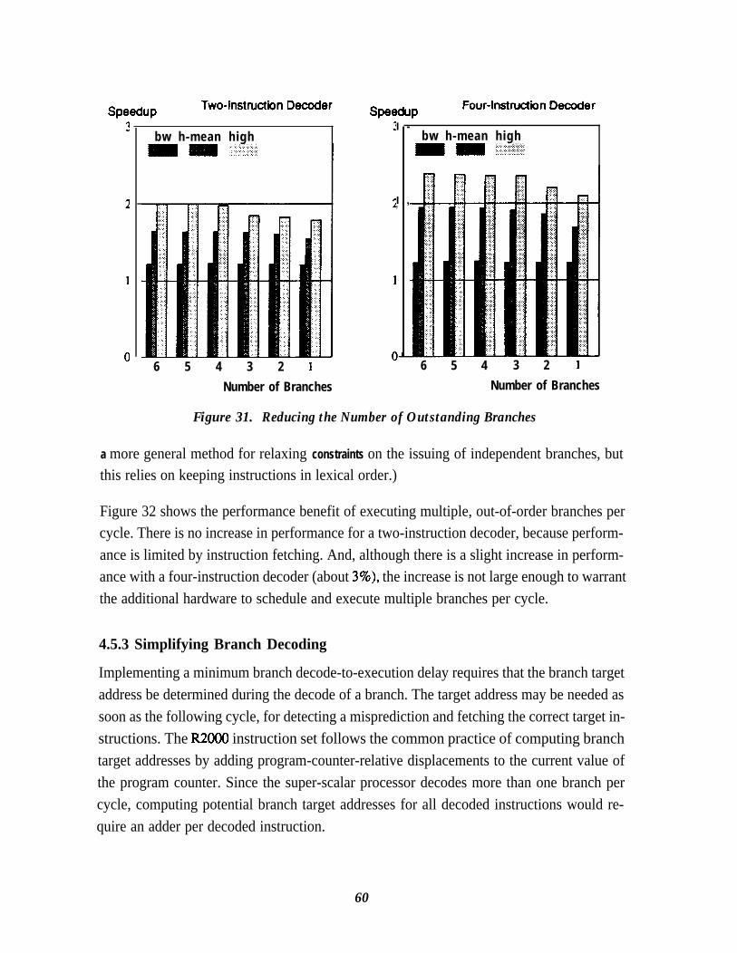
speedup ruurwismmun uuwaur
bw h-mean high
6 5 4 3 2 1Number of Branches Number of Branches
I -
I , ,,
bw h-mean highm = g+$$$$
6 5 4 3 2 1
Figure 31. Reducing the Number of Outstanding Branches
a more general method for relaxing constraints on the issuing of independent branches, butthis relies on keeping instructions in lexical order.)
Figure 32 shows the performance benefit of executing multiple, out-of-order branches percycle. There is no increase in performance for a two-instruction decoder, because perform-ance is limited by instruction fetching. And, although there is a slight increase in perform-ance with a four-instruction decoder (about 3%), the increase is not large enough to warrantthe additional hardware to schedule and execute multiple branches per cycle.
4.5.3 Simplifying Branch Decoding
Implementing a minimum branch decode-to-execution delay requires that the branch targetaddress be determined during the decode of a branch. The target address may be needed assoon as the following cycle, for detecting a misprediction and fetching the correct target in-structions. The R2000 instruction set follows the common practice of computing branchtarget addresses by adding program-counter-relative displacements to the current value ofthe program counter. Since the super-scalar processor decodes more than one branch percycle, computing potential branch target addresses for all decoded instructions would re-quire an adder per decoded instruction.
60

SpeduPTwo-Instruction Decoder
SpeeduPFour-Instruction Decoder
bw h-mean high
p=d multiple branches
bw h-mean highm 111 :...:.:j.:i’.:‘:. . . . .:. ::,7
multiple branches
Figure 32. Pe@onnmce Increase by Executing MultipleCorrectly-Predicted Branches Per Cycle
Fortunately, there is not a strong need to compute more than one branch target address perdecode cycle. As Figure 33 shows, there is only a slight performance decrease (about 2%)caused by imposing a limit on the decoder of one target address per cycle. The decrease isslight because the branch-prediction logic is limited to predicting one branch per cycle, andthe execution hardware is limited to executing only one branch per cycle. Placing the addi-tional limit in the decode stage may occasionally stall the decoding of a second branch andsubsequent instructions, but this limit is not severe compared to the other branch limits. Thelimit can be avoided if the relative-address computation is performed during the executionof the branch rather than during decode, in which case all decoded branches are simplyplaced into the branch reservation station. This adds a cycle to the best-case branch delay,and increases the penalty for a mispredicted branch.
Even though there is only one target-address adder, computing the target address is stillmore complex than in the scalar processor. Instructions in the decoder must arbitrate for theaddress-computation hardware, with the first branch instruction having priority. Also, theprogram-counter-relative computation must take into account the position of the branch in-struction in the decoder, because there is only a single program counter for the entire decodestage.
61

W=JUP Two-Instruction Decoder Four-Instruction Decoder
bw h-mean high
PM decode one target
bw h-mean high
decode one target
Figure 33. Pelfonnance Decrease Caused by ComputingOne Branch Target Address Per Decode Cycle
4.6 Observations and Conclusions
To sustain high instruction throughput, an instruction fetcher for a super-scalar processormust be able to fetch successive runs of instructions without intervening delay, and shouldhave a wide (four-instruction) decoder. The instruction fetcher also should be able to fetchthrough as many as four runs of instructions before an unresolved branch can stall the de-coder. Within this framework, software can help improve instruction-fetch efficiency byaligning and merging instructions runs, and by allocating decoder resources (specifically,register-file read ports) so that high performance is obtained with relatively simple hard-ware.
Hardware branch prediction can be added to the instruction cache for a small relative cost.Alternatively, software branch prediction incurs almost no hardware cost, and has the addedadvantage that software can, based on the software prediction, align and merge instructionruns. Although this study does not examine software branch prediction, aligning, and merg-ing in detail, its results indicate that software branch prediction is about as accurate as hard:ware branch prediction, and that software aligning and merging can increase performanceby about 5% (this improvement is in addition to other softwa scheduling to improve in-struction independence). However, if software branch prediction is used, the instruction
62

fetcher must still be able to fetch instruction runs without intervening delays; the instruction-set architecture cannot have fully-general relative branches, and branches must be readilyidentifiable by fetch hardware.
A four-instruction decoder provides a higher sustained instruction bandwidth than a two-in-struction decoder, and also allows a higher peak execution rate. With software support, thefour-instruction decoder can be constructed without the eight register-file read ports that areimplied by a simplistic implementation. A two-instruction decoder may be an adequate al-ternative if software techniques alone are used to schedule instructions. In the latter case,both the execution hardware and the decoder are simpler, though performance is lower. Thedecision between a two-instruction and a four-instruction decoder can also depend on theposition of instruction cache with respect to the processor. If these are on separate chips, itmay be too expensive to communicate four instructions in a single cycle. Throughout theremainder of this study, performance results are shown for both two-instruction and four-in-struction decoders.
Since efficient instruction fetching relies on some sort of branch prediction, there must be amechanism for undoing the effect of instructions executed along a mispredicted path. Thismechanism, and its relationship to register renaming, is the topic of the following chapter.
63

Chapter 5Operand Management
A super-scalar processor achieves high instruction throughput by fetching and issuing in-structions under the assumption that branches are ptedicted correctly and that exceptions donot occur. This allows instruction execution to proceed without waiting on the completionof previous instructions. However, the processor must produce correct results even whenthese assumptions fail. Correct operation requires restart mechanisms for canceling the ef-fects of instructions that were issued under false assumptions. Fortunately, the restartmechanism added to the processor can also support register renaming, improving the per-formance of out-of-order issue.
Sustaining a high instruction throughput also requires a high operand-transfer rate. Highperformance requires multiple result buses and bypass paths to forward results directly towaiting instructions. Moreover, the processor requires mechanisms to control the routing ofoperand values to instructions and to insure that instructions are not issued until all inputoperands are valid. This chapter examines the magnitude of this hardware and the perform-ance it provides. Supplying operands for instructions is complicated by the fact that theprocessor, on every cycle, can be generating multiple, out-of-order results and attempting toprepare multiple instructions for issue.
Finally, this chapter explores the complexity of implementing restart, register renaming, andresult forwarding. This hardware is complex, but there are no simple hardware alternativesthat provide nearly the same performance.
5.1 Buffering State Information for Restart
The implementation of precise interrupts with out-of-order completion requires buffering sothat the processor can maintain both the state required for computation and the state requiredfor precise interrupts. This section describes the different types of state information to bemaintained and describes four previously-proposed buffering techniques that maintain thisinformation: checkpoint repair, a history buffer, a reorder buffer, and a future file. This sec-tion contrasts the four buffering techniques, and will show that either the reorder buffer orthe future file is appropriate for restarting a super-scalar processor. Section 5.3 later consid-ers the roles of the reorder buffer and future file in analyzing and enforcing data dependen-cies, and concludes that the reorder buffer is preferred.
64

5.1.1 Sequential, Look-Ahead, and Architectural State
To aid understanding of the mechanisms for precise interrupts, this section introduces theconcepts of sequential, look-ahead, and architectzual state, illustrated in Figure 34.Figure 34 shows the register assignments performed by a sequence of instructions: in thissequence, completed instruction are shown in boldface.
The sequential state is made up of the most recent assignments performed by the longestuninterrupted sequence of completed instructions. In Figure 34, the assignments performedby three of the first four instructions of the sequence are part of the sequential state (as areassignments performed by previous instructions not shown and assumed completed). Theassignment to R7 in the second instruction does not appear in the sequential state because ithas been superseded by the assignment to R7 in the fourth instruction. Though the sixthinstruction is shown completed, its assignment is not part of the sequential state because ithas completed out-of-order: the fifth instruction has not yet completed
All assignments starting with the first uncompleted instruction are part of the look-aheadstate, and are shown italicized in Figure 34. The look-ahead state is made up of actual regis-ter values as well as pending updates, since there are both completed and uncompleted in-structions (in the hardware, pending updates are represented by tags). Because of possibleexceptions, all assignments are retained in the look-ahead state. For example, the assign-ment to R3 in the sixth instruction is not superseded by the assignment to R3 in the eighthinstruction; both assignments should be considered part of the look-ahead state and added inproper order to the sequential state. To further illustrate how the look-ahead state is added tothe sequential state, the assignments of the fifth and sixth instructions will become part of thesequential state as soon as the fifth instruction completes successfully, and at that time the
instructionsequence
items insequential
state
items in items inlook-ahead architectural
state state
R3 := . . . (11 R3 := . ..I11
R7 := . . . (2)
R8 := . . .fJ) R8 := . ..(J)
R7 := . . . (.I R7 := . . .to R7 := . . .14)R4 := . ..lS) R4 := . . . OJ R4 := . . . IS)
R3 := . ..(61 R3 := . . . (61
R8 := . ..(.I) R8 := . . .I’II R8 := . ..171
R 3 := . ..((I R3 := . . . (81 R3 I= . . .(a)
Figure 34. Illustration of Sequential, Look-Ahead, and Architectural State
65

assignment to R3 in the sixth instruction will suppress the assignment to R3 in the first in-struction.
The architectural state consists of the most recently completed and pending assignments foreach register, relative to the end of the instruction sequence. This is the state that must beaccessed by an instruction following this sequence, for correct operation. In the architec-tural state, the pending assignment to R3 in the eighth instruction supersedes the completedassignment to R3 in the sixth instruction, because a subsequent instruction must get the mostrecent value assigned to R3. If a subsequent instruction accessing R3 were decoded beforethe eighth instruction completed, the decoded instruction would obtain a tag for the newvalue of R3, rather than an old value for R3. Note that the architectural state is not separatefrom the sequential and look-ahead states, but is obtained by combining these states.
All hardware implementations of precise interrupts described in the following sections mustcorrectly maintain the sequential, look-ahead, and architectural states. These implementa-tions differ primarily in the mechanisms used to isolate and maintain these sets of state.
5.1.2 Checkpoint Repair
Hwu and Patt [ 19871 describe the use of checkpoint repair to recover from mispredictedbranches and exceptions. The processor provides a set of logical spaces, where each logicalspace consists of a full set of software-visible registers and memory. Of all the logicalspaces, only one is used for current execution. The other logical spaces contain backup cop-ies of sequential state that correspond to some previous point in execution. A various timesduring execution, a checkpoint is made by copying the contents of the current logical spaceto a backup space. Logical spaces are managed as a queue, so making a checkpoint discardsthe oldest checkpointed state. The copied state is not necessarily the sequential state at thattime, but the checkpointed state is updated, as instructions complete, to bring it to the desiredsequential state. After the checkpoint is made, computation continues in the current logicalspace. Restart is accomplished, if required, by loading the contents of the appropriatebackup logical space into the current logical space; the backup space used to restart statedepends on the location of the fault with respect to the location of the checkpoint in the in-struction sequence.
Hwu and Patt propose two checkpoint mechanisms: one for exceptions, and one forr&predicted branches. This approach is based on presumed differences between exceptionrestart and misprediction restart, and is intended to reduce the number of logical spaces re-quired. Exceptions can happen at any instruction in the sequence, but exception restart is
66
required infrequently. Thus, checkpoints for exception restart can be made infrequently andat widely-separated points in the instruction sequence. If an exception does occur, the proc-essor recovers the state at the exception point by reloading the checkpoint preceding the ex-ception point (this may be the state several instructions before the point of exception) andexecuting instructions sequentially up to the point of the exception. In contrast, mispredict-ion occurs only at branch points, and misprediction restart is required frequently. Thus,checkpoints for misprediction restart are made at every branch point, and contain the precisestate to restart execution immediately after the mispredicted branch.
To avoid the time spent copying state to the backup logical spaces, Hwu and Patt proposeimplementing the logical spaces with multiple-bit storage cells. For example, each bit in theregister file might be implemented by four bits of storage: one bit for the current logicalspace and three bits for three backup logical spaces. This complexity is the most seriousdisadvantage of this proposal. There is a tremendous amount of storage for the logicalspaces, but the contents of these spaces differ only by a few locations (depending on thenumber of results produced between checkpoints). It is much more efficient to simply main-tain these state differences in a dedicated structure such as the reorder buffer described inSection 51.4. Because of this inefficiency, checkpoint repair is not an appropriate restartmechanism.
5.1.3 History Buffer
Figure 35 shows the organization of a history buffer. The history buffer was proposed bySmith and Pleszkun [ 19851 as a means for implementing precise interrupts in a pipelinedscalar processor with out-of-order completion. In this organization, the register file containsthe architectural state, and the history buffer stores items of the sequential state which havebeen superseded by items of look-ahead state. The look-ahead state is not maintained sepa-rately, but is part of the state in both the register file and the history buffer.
The history buffer is managed as a FIFO. When an instruction is decoded, the current valueof the instruction’s destination register is copied to the history buffer. When a value reachesthe head of the history buffer, it is discarded if the associated instruction (that is, the instruc-tion that caused the value to be placed into the history buffer) completed successfully. If thisinstruction has not completed, the history buffer does not advance until the instruction doescomplete. If the instruction completes with an exception, all other pending instructions arecompleted, then all active values in the history buffer are copied-from tail to head-backinto the register file. This restores the register file to the sequential state at the point of theexception. Values are copied from tail to head so that, if there are multiple values for the
67

instruction sequential state re-resutts stored on exception
11 II 11RegisterRegister HistoryHistory
FileFile BufferBuffer
I I1
1 superseded itemssuperseded itemsinstructioninstruction of sequentialof sequentialoperandsoperands statestate
Figure 35. History Buffer OrganizationFigure 35. History Buffer Organization
same register, the oldest value will be placed into the register file last+%her values are partof the look-ahead state.
Unfortunately, the history buffer has two significant disadvantages that are avoided by otherschemes presented below. First, it requires additional ports on the register file for transfer-ring the superseded values into the history buffer. For example, a four-instruction decoderwould require as many as four additional ports for reading result-register values. These ad-ditional ports contribute nothing to performance. Second, the history buffer requires severalcycles to restore the sequential state into the register file. These cycles are probably unim-portant for exceptions, because exceptions are generally infrequent. However, the addi-tional cycles are excessive for m&predicted branches. For these reasons, the history buffer isinappropriate for restart in a super-scalar processor.
5.1.4 Reorder Buffer
Figure 36 shows the organization of a reorder beer [Smith and Pleszkun 19851. In thisorganization, the register file contains the sequential state, and the reorder buffer containsthe look-ahead state. The architectural state is obtained by combining the sequential andlook-ahead states and ignoring all but the most recent updates to each register. Pleszkun etal. [ 19871 and Sohi and Vajapeyam [ 19871 demonstrate ways to unify the sequential andlook-ahead states using software and associative hardware, respectively.
As with the history buffer, the reorder buffer is also managed as a FIFO. When an instructionis decoded, it is allocated an entry in the reorder buffer. The result value of the instruction iswritten into the allocated entry after the instruction completes. When the value reaches the
68
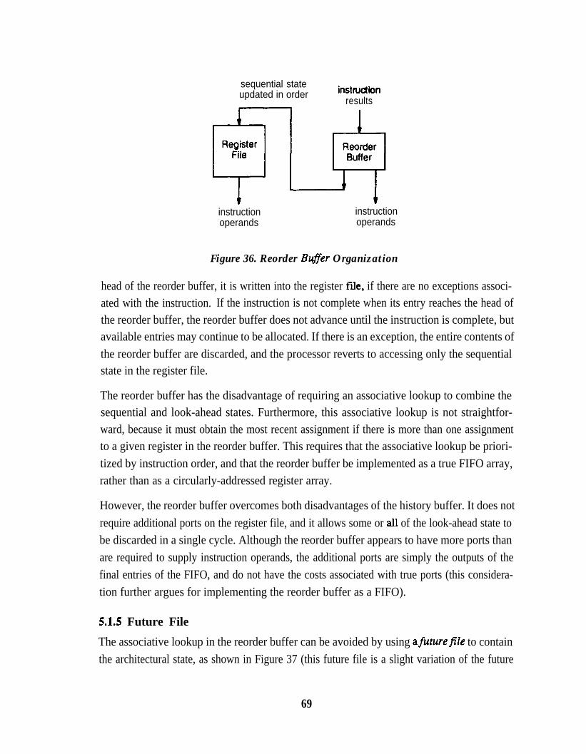
sequential stateupdated in order instfuction
results
instructionoperands
instructionoperands
Figure 36. Reorder ByYer Organization
head of the reorder buffer, it is written into the register file, if there are no exceptions associ-ated with the instruction. If the instruction is not complete when its entry reaches the head ofthe reorder buffer, the reorder buffer does not advance until the instruction is complete, butavailable entries may continue to be allocated. If there is an exception, the entire contents ofthe reorder buffer are discarded, and the processor reverts to accessing only the sequentialstate in the register file.
The reorder buffer has the disadvantage of requiring an associative lookup to combine thesequential and look-ahead states. Furthermore, this associative lookup is not straightfor-ward, because it must obtain the most recent assignment if there is more than one assignmentto a given register in the reorder buffer. This requires that the associative lookup be priori-tized by instruction order, and that the reorder buffer be implemented as a true FIFO array,rather than as a circularly-addressed register array.
However, the reorder buffer overcomes both disadvantages of the history buffer. It does notrequire additional ports on the register file, and it allows some or all of the look-ahead state tobe discarded in a single cycle. Although the reorder buffer appears to have more ports thanare required to supply instruction operands, the additional ports are simply the outputs of thefinal entries of the FIFO, and do not have the costs associated with true ports (this considera-tion further argues for implementing the reorder buffer as a FIFO).
5.1.5 Future File
The associative lookup in the reorder buffer can be avoided by using afumrefile to containthe architectural state, as shown in Figure 37 (this future file is a slight variation of the future
69
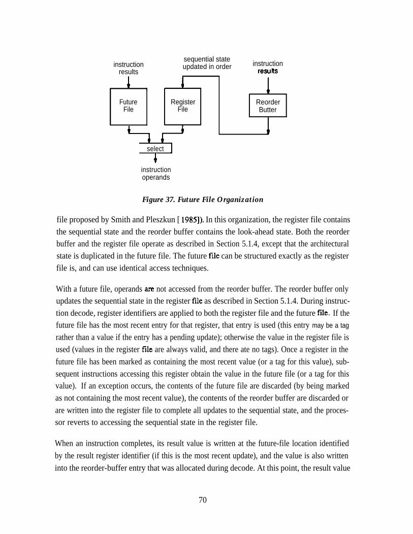
instructionresults
sequential stateupdated in order instruction
resutts
I I* IFuture Register Reorder
File File Butter
1I i
1 I
select
4instructionoperands
Figure 37. Future File Organization
file proposed by Smith and Pleszkun [ 19851). In this organization, the register file containsthe sequential state and the reorder buffer contains the look-ahead state. Both the reorderbuffer and the register file operate as described in Section 5.1.4, except that the architecturalstate is duplicated in the future file. The future file can be structured exactly as the registerfile is, and can use identical access techniques.
With a future file, operands axe not accessed from the reorder buffer. The reorder buffer onlyupdates the sequential state in the register Ne as described in Section 5.1.4. During instruc-tion decode, register identifiers are applied to both the register file and the future file. If thefuture file has the most recent entry for that register, that entry is used (this entry may be a tag
rather than a value if the entry has a pending update); otherwise the value in the register file isused (values in the register file are always valid, and there ate no tags). Once a register in thefuture file has been marked as containing the most recent value (or a tag for this value), sub-sequent instructions accessing this register obtain the value in the future file (or a tag for thisvalue). If an exception occurs, the contents of the future file are discarded (by being markedas not containing the most recent value), the contents of the reorder buffer are discarded orare written into the register file to complete all updates to the sequential state, and the proces-sor reverts to accessing the sequential state in the register file.
When an instruction completes, its result value is written at the future-file location identifiedby the result register identifier (if this is the most recent update), and the value is also writteninto the reorder-buffer entry that was allocated during decode. At this point, the result value
70

in the future file has been marked as the most recent value, causing it to effectively replacethe value in the register file. Once an entry is marked as most recent, it remains valid untilthe next exception occurs (it may still contain a tag instead of a value at various times duringexecution).
The future file described by Smith and Pleszkun [ 19851 is slightly different than the futurefile described here, because, in their organization, only the future file provides operands.Their scheme uses the register file to communicate the sequential state to an exception han-dler. The scheme described here allows both the future file and the register fiIe to provideoperands. This permits quick restart after a mispredicted branch, because the register filecan supply all operands after restart, without any copying to the future file.
The future file overcomes the disadvantages of the history buffer without the associativecomparators of the reorder buffer. However, this advantage is at the expense of an additionalarray (the future file) and validity and tag bits associated with entries of this array.
5.2 Restart Implementation and Effects on Performance
Given that the processor contains adequate buffering to restart execution at a previous ver-sion of the processor state, there are still the problems of identifying this version of state andeither reinitiating execution or reporting the state to an exception handler. The processorshould restart automatically after a mispredicted branch, to avoid excessive penalties formisprediction. To allow restart after an exception, the processor simply communicates aconsistent sequential state to software.
5.2.1 Mispredicted Branches
Sohi and Vajapeyam [ 19871 mention, as a subject for future research, using a reorder bufferto restart after a mispredicted branch. In general, branch recovery is straightforward exceptfor the proper handling of instructions preceding the mispredicted branch. Figure 38 showsthe action required to correct the processor state if a r&predicted branch follows the sixthinstruction in the sequence of Figure 34. The state must be backed up to the point of then&predicted branch, but it is not correct to discard the entire look-ahead state, because someof this state is associated with incomplete instructions which preceded the branch. Theseitems in the look-ahead state must be preserved. Furthermore, each previously-supersededvalue in the look-ahead state must be “uncovered” so that subsequent instructions obtaincorrect operands values.
71
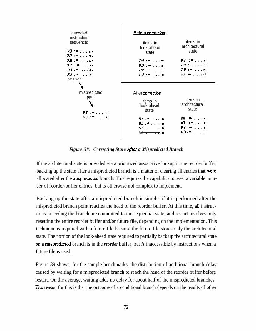
decodedinstructionsequence:
R3 := . . . (11R7 := . . . (IIR8 := . . .l3)R7 := . ..(4). . . (5)2 ir . . . (6)branch
mispredictedpath
RB := . . . (71R3 := . ..(#I
items in items inlook-ahead architectural
state state
R4 := . ..ts) R7 := . . .I4)
R3 := . ..(C) R4 := . ..ISIR8 :- . ..cT) R8 := . ..(l)R3 := . ..(I) R3 := . ..(a)
After corrective:
items inlook-ahead
stateR4 := . ..oIm := . . . (61
Rd . . . .I71A3 . . . .I0
items inarchitectural
state
R8 := . ..l3)R7 := . ..(4)
R4 := . ..(s)m := . . . (6)
Figure 38. Correcting State Afrer a Mispredicted Branch
If the architectural state is provided via a prioritized associative lookup in the reorder buffer,backing up the state after a mispredicted branch is a matter of clearing all entries that wefeallocated after the n&predicted branch. This requires the capability to reset a variable num-ber of reorder-buffer entries, but is otherwise not complex to implement.
Backing up the state after a mispredicted branch is simpler if it is performed after themispredicted branch point reaches the head of the reorder buffer. At this time, all instruc-tions preceding the branch are committed to the sequential state, and restart involves onlyresetting the entire reorder buffer and/or future file, depending on the implementation. Thistechnique is required with a future file because the future file stores only the architecturalstate. The portion of the look-ahead state required to partially back up the architectural stateon a n&predicted branch is in the reorder buffer, but is inaccessible by instructions when afuture file is used.
Figure 39 shows, for the sample benchmarks, the distribution of additional branch delaycaused by waiting for a mispredicted branch to reach the head of the reorder buffer beforerestart. On the average, waiting adds no delay for about half of the mispredicted branches.The reason for this is that the outcome of a conditional branch depends on the results of other
72
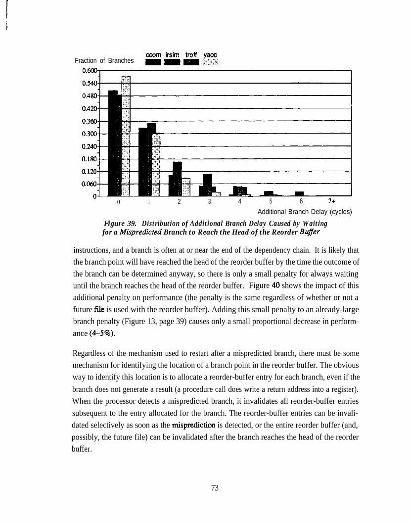
Fraction of Branches
I”0 1 2 3 4 5 6 7+
Additional Branch Delay (cycles)
Figure 39. Distribution of Additional Branch Delay Caused by Waitingfor a Mispredicted Branch to Reach the Head of the Reorder %@er
instructions, and a branch is often at or near the end of the dependency chain. It is likely thatthe branch point will have reached the head of the reorder buffer by the time the outcome ofthe branch can be determined anyway, so there is only a small penalty for always waitinguntil the branch reaches the head of the reorder buffer. Figure 40 shows the impact of thisadditional penalty on performance (the penalty is the same regardless of whether or not afuture Ne is used with the reorder buffer). Adding this small penalty to an already-largebranch penalty (Figure 13, page 39) causes only a small proportional decrease in perform-ance (4-5s).
Regardless of the mechanism used to restart after a mispredicted branch, there must be somemechanism for identifying the location of a branch point in the reorder buffer. The obviousway to identify this location is to allocate a reorder-buffer entry for each branch, even if thebranch does not generate a result (a procedure call does write a return address into a register).When the processor detects a mispredicted branch, it invalidates all reorder-buffer entriessubsequent to the entry allocated for the branch. The reorder-buffer entries can be invali-dated selectively as soon as the n&prediction is detected, or the entire reorder buffer (and,possibly, the future file) can be invalidated after the branch reaches the head of the reorderbuffer.
73
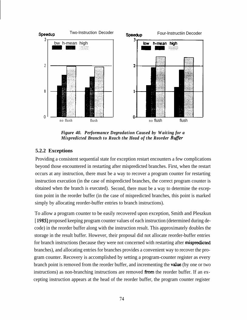
Two-Instruction Decoder
bw h-mean high
SpeefjUP?
2
1
0no flush flush
Four-lnstructiin Decoder
no flush flush
Figure 40. Performance Degradation Caused by Waiting for aMispredicted Branch to Reach the Head of the Reorder Buffer
5.2.2 Exceptions
Providing a consistent sequential state for exception restart encounters a few complicationsbeyond those encountered in restarting after mispredicted branches. First, when the restartoccurs at any instruction, there must be a way to recover a program counter for restartinginstruction execution (in the case of mispredicted branches, the correct program counter isobtained when the branch is executed). Second, there must be a way to determine the excep-tion point in the reorder buffer (in the case of mispredicted branches, this point is markedsimply by allocating reorder-buffer entries to branch instructions).
To allow a program counter to be easily recovered upon exception, Smith and Pleszkun[ 19851 proposed keeping program counter values of each instruction (determined during de-code) in the reorder buffer along with the instruction result. This approximately doubles thestorage in the result buffer. However, their proposal did not allocate reorder-buffer entriesfor branch instructions (because they were not concerned with restarting after r&predictedbranches), and allocating entries for branches provides a convenient way to recover the pro-gram counter. Recovery is accomplished by setting a program-counter register as everybranch point is removed from the reorder buffer, and incrementing the value (by one or twoinstructions) as non-branching instructions are removed from the reorder buffer. If an ex-cepting instruction appears at the head of the reorder buffer, the program counter register
74

indicates the location of this instruction in memory. Note that maintaining a correct programcounter requires that ail instructions be allocated reorder-buffer entries, rather than justthose that write registers. This is one reason for allocating a reorder-buffer entry for eachinstruction; other reasons are presented below.
Determining the location of excepting instructions in the reorder buffer requires that the re-order buffer be augmented with a few bits of instruction state to indicate whether or not theassociated instruction completed successfully. This state information can also be used toindicate the location of branch points, for uniformity. Indicating exceptions in this manneralso requires that each instruction be allocated a reorder-buffer entry, whether or not it writesa processor register. An instruction may create an exception even though it does not write aregister (e.g. a store). Furthermore, because exceptions are independent of register results,‘the instruction-state information in the reorder buffer must be written independently of otherresults.
An additional advantage to allocating a reorder-buffer entry for every instruction is that itprovides a convenient mechanism for releasing stores to the data cache so that the sequentialstate is preserved in memory [Smith and Pleszkun 19851. By keeping identifiers for the storebuffer in the reorder buffer, the reorder buffer can signal the release of store-buffer entries asthe corresponding stores reach the head of the result buffer. If the store buffer is allocatedduring the decode stage, store-buffer identifiers are readily available to be placed into thereorder buffer. After being released in this manner, store exceptions (e.g. bus errors) are notrestartable unless there is some other mechanism to allow restart.
It is also simpler for the decoder to allocate a reorder-buffer entry for every instruction thanto allocate an entry just for those instructions which generate results. The decoder need onlydetermine which instructions are valid (as determined during instruction fetch), rather thanalso determine which instructions generate results.
The essential advantage of allocating a reorder-buffer entry for every instruction is that itpreserves instruction-sequence information even with out-of-order issue. This informationis useful for a variety of purposes.
5.2.3 Effect of Restart Hardware on Performance
The limited size of the reorder buffer-whether or not it is used with a future file-can re-duce performance. Instruction decoding stalls when there is no available reorder-buffer en-try to receive the result of a decoded instruction. (The history buffer, if used, would have an
75
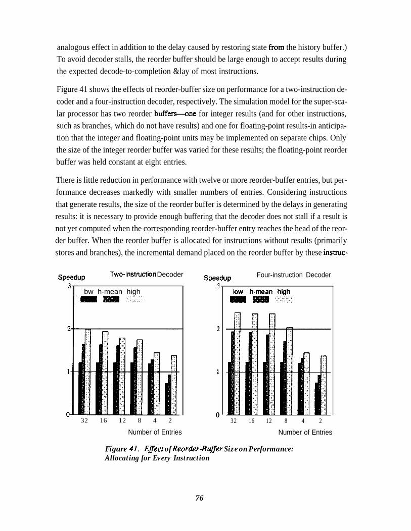
analogous effect in addition to the delay caused by restoring state from the history buffer.)To avoid decoder stalls, the reorder buffer should be large enough to accept results duringthe expected decode-to-completion &lay of most instructions.
Figure 41 shows the effects of reorder-buffer size on performance for a two-instruction de-coder and a four-instruction decoder, respectively. The simulation model for the super-sca-lar processor has two reorder buffeMne for integer results (and for other instructions,such as branches, which do not have results) and one for floating-point results-in anticipa-tion that the integer and floating-point units may be implemented on separate chips. Onlythe size of the integer reorder buffer was varied for these results; the floating-point reorderbuffer was held constant at eight entries.
There is little reduction in performance with twelve or more reorder-buffer entries, but per-formance decreases markedly with smaller numbers of entries. Considering instructionsthat generate results, the size of the reorder buffer is determined by the delays in generatingresults: it is necessary to provide enough buffering that the decoder does not stall if a result isnot yet computed when the corresponding reorder-buffer entry reaches the head of the reor-der buffer. When the reorder buffer is allocated for instructions without results (primarilystores and branches), the incremental demand placed on the reorder buffer by these instruc-
Speedup Two-lnstnxtbn Decoder Speedup Four-instruction Decoder
bw h-mean high
32 16 12 8 4 2
Number of Entries
32 16 12 8 4 2
Number of Entries
Figure 41. Eflect of Reorder-Buffer Size on Performance:Allocating for Every Instruction
76
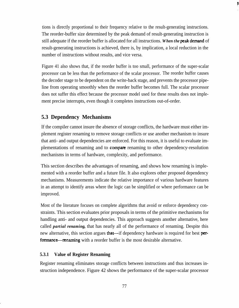
tions is directly proportional to their frequency relative to the result-generating instructions.The reorder-buffer size determined by the peak demand of result-generating instruction isstill adequate if the reorder buffer is allocated for all instructions. When the peak demand ofresult-generating instructions is achieved, there is, by implication, a local reduction in thenumber of instructions without results, and vice versa.
Figure 41 also shows that, if the reorder buffer is too small, performance of the super-scalarprocessor can be less than the performance of the scalar processor. The reorder buffer causesthe decoder stage to be dependent on the write-back stage, and prevents the processor pipe-line from operating smoothly when the reorder buffer becomes full. The scalar processordoes not suffer this effect because the processor model used for these results does not imple-ment precise interrupts, even though it completes instructions out-of-order.
5.3 Dependency Mechanisms
If the compiler cannot insure the absence of storage conflicts, the hardware must either im-plement register renaming to remove storage conflicts or use another mechanism to insurethat anti- and output dependencies are enforced. For this reason, it is useful to evaluate im-plementations of renaming and to cornpane renaming to other dependency-resolutionmechanisms in terms of hardware, complexity, and performance.
This section describes the advantages of renaming, and shows how renaming is imple-mented with a reorder buffer and a future file. It also explores other proposed dependencymechanisms. Measurements indicate the relative importance of various hardware featuresin an attempt to identify areas where the logic can be simplified or where performance can beimproved.
Most of the literature focuses on complete algorithms that avoid or enforce dependency con-straints. This section evaluates prior proposals in terms of the primitive mechanisms forhandling anti- and output dependencies. This approach suggests another alternative, herecalled partial renaming, that has nearly all of the performance of renaming. Despite thisnew alternative, this section argues that-if dependency hardware is required for best per-formance-renaming with a reorder buffer is the most desirable alternative.
5.3.1 Value of Register Renaming
Register renaming eliminates storage conflicts between instructions and thus increases in-struction independence. Figure 42 shows the performance of the super-scalar processor
77

Spedup3
2
1
0
Two-Instruction Decoder
bw h-mean high
rename no rename
SpeduPFour-instruction Decoder
rename no rename
Figure 42. Reducing Concurrency by Eliminating Register Renaming
with and without register renaming. For these results, the processor uses Weiss and Smith’s[ 19841 variation of Thor-ton’s algorithm [Thotton 19701 to resolve dependencies in the “norename” case: instruction decoding is stalled whenever a decoded instruction will createmore than one instance of a register value. Eliminating renaming reduces performance byabout 15% with a two-instruction decoder and by about 21% with a four-instruction de-coder. It should be emphasized that these results are based on code generated by a compilerthat performs aggressive register allocation, and this exaggerates the advantage of registerrenaming because registers are often reused. An architecture with a larger number of regis-ters and different compiler technology would not experience the same advantage, but thedegree to which this is true is unknown.
5.3.2 Register Renaming with a Reorder Buffer
A reorder buffer that uses associative lookup to implement the architectural state (Section5.1.4) provides a straightforward implementation of register renaming. The associativelookup maps the register identifier to the reorder-buffer entry as soon as the entry is allo-cated, and the lookup is prioritized so that only the value for the most recent assignment isobtained (a tag for this value is obtained if the result is not yet available). There can be asmany instances of a given register as there are reorder-buffer entries, so there are no storageconflicts between instructions. The values for the different instances are written to the
78

register file in sequential order. When the value for the final instance is written to the registerfile, the reorder buffer no longer maps the register, and the register file contains the onlyinstance of the register.
5.3.3 Renaming with a Future File: Tomasulo’s Algorithm
Tomasulo’s algorithm [Tomasulo 19671 implements renaming by associating a tag witheach register that has at least one pending update. This tag identifies the most recent value tobe assigned to the register (in To~~su~o’s implementation, the tag was the identifier of thereservation station containing the assigning instruction, but, as Weiss and Smith [1984]point out, the tag can be any unique identifier). When an instruction is deem it accessesregister tags along with the contents of the operand registers. If the register has one or morepending updates, the tag identifies the update value required by the decoded instruction.Once an instruction is decoded, other instructions may overwrite this instruction’s sourceoperands without being constrained by anti-dependencies. Output dependencies are han-dled by preventing result writing if the associated instruction does not have a tag for the mostrecent value. Both anti- and output dependencies are handled without stalling instructionissue.
Tomsulo’s algorithm is easily adapted to an implementation using a future file by placingthe tag logic into the future file rather than in the register file. The future file requires that thetag array have four write ports which are separate from the result write ports, because tagsare written immediately after decode rather than after instruction completion. Also, the tagarray has two read ports so that tags may be compared before write-back, to prevent the writ-ing of an old value. Finally, this implementation requires storage for the future file as well asstorage for the reorder buffer.
5.3.4 Other Mechanisms to Resolve Anti-Dependencies
This section explores alternative mechanisms for handling anti-dependencies, in an attemptto identify a dependency mechanism that is simpler than renaming. There are two ap-proaches to resolving anti-dependencies. First, anti-dependencies can be enforced by delay-ing the issue of any instruction that might overwrite the source operands of unissued instruc-tions. Tomg [ 19841 and Acosta et al. [ 19861 describe such an approach using an instructionwindow called a dispatch stack. Alternatively, anti-dependencies can be avoided altogetherby copying operands to dedicated buffers (e.g. reservation stations) during decode so thatthey cannot be overwritten by other register updates [Weiss and Smith 19841.
79
Of these two alternatives, copying operands is preferred, because it allows register accessesto be performed only once, in parallel with dependency checking. Register access is not re-peated later when the instruction is issued, as it is in the Crst approach. The primary motiva-tion of holding issue in the frost approach is to avoid the additional storage to hold copies ofoperands; however, accessing registers just before instruction issue introduces additional is-sue latency and reduces performance. In addition, delaying issue for anti-dependencies re-quires comparing destination-register identifiers to all source-register identifiers of previ-ous instructions. This comparison is somewhat costly and unnatural (Dwyer and Tomg[ 19871 give a good illustration), considering the number of combinations of source and des-tination operands to be compared and the need to release dependencies using source-registeridentifiers as a trigger rather than destination-register identifiers. These considerations out-weigh any concern over the extra storage for operand copies.
It should be noted that copying operands simplifies the implementation of renaming[Tomasulo 19671 but is not sufficient to implement renaming because it does not enforceoutput dependencies. Copying operands simplifies renaming because it permits register ac-cess to be performed only once, and it permits a renaming mapping to be discarded immedi-ately when the associated register must be renamed again. Without operand copying, itwould be necessary to track each use of the old mapping and discard the mapping only afterthere were no remaining uses. Note that, in some cases, result forwarding (Section 5.5) sup-plies the operand for the old mapping after the mapping is discarded.
Any approach involving the copying of operands must correctly handle the situation wherethe operand value is not available when it is accessed. Stalling the decoder in this situationgreatly reduces performance (this approaches the performance with in-order issue), so amore common solution is to supply a tag for the operand rather than the operand itself. Thistag is also associated with the corresponding result value, so that the operand is obtained byforwarding when the result is eventually written. If there can be only one pending update to aregister, the register identifier can serve as a tag. If there can be more than one pending up-date to a register (allowing more than one pending update avoids stalling the decoder foroutput dependencies and yields higher performance), there must be a mechanism for allocat-ing result tags and insuring uniqueness.
5.3.5 Other Mechanisms to Resolve Output Dependencies
This section explores alternative mechanisms for handling output dependencies, again in anattempt to identify a dependency mechanism that is simpler than renaming. As with anti-de-pendencies, there are two approaches to resolving output-dependencies. First, output-
80
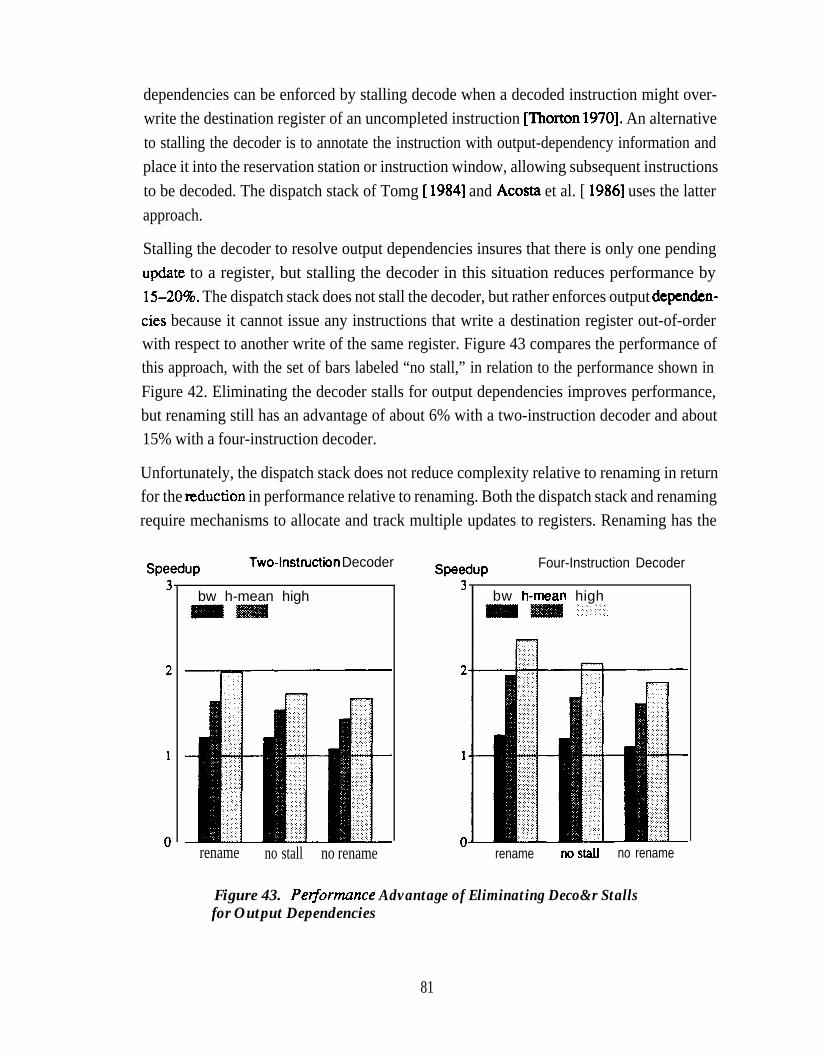
dependencies can be enforced by stalling decode when a decoded instruction might over-write the destination register of an uncompleted instruction [Thorton 19701. An alternativeto stalling the decoder is to annotate the instruction with output-dependency information andplace it into the reservation station or instruction window, allowing subsequent instructionsto be decoded. The dispatch stack of Tomg [ 19841 and Acosta et al. [ 19861 uses the latterapproach.
Stalling the decoder to resolve output dependencies insures that there is only one pendingupdate to a register, but stalling the decoder in this situation reduces performance by15-20%. The dispatch stack does not stall the decoder, but rather enforces output &penden-ties because it cannot issue any instructions that write a destination register out-of-orderwith respect to another write of the same register. Figure 43 compares the performance ofthis approach, with the set of bars labeled “no stall,” in relation to the performance shown inFigure 42. Eliminating the decoder stalls for output dependencies improves performance,but renaming still has an advantage of about 6% with a two-instruction decoder and about15% with a four-instruction decoder.
Unfortunately, the dispatch stack does not reduce complexity relative to renaming in returnfor the teduction in performance relative to renaming. Both the dispatch stack and renamingrequire mechanisms to allocate and track multiple updates to registers. Renaming has the
Speedup Two-lnstnrctbn Decoder Speedup Four-Instruction Decoder
bw h-mean high
rename no stall no rename
bw h-mean high
rename llOStdl no rename
Figure 43. PerJormance Advantage of Eliminating Deco&r Stallsfor Output Dependencies
81
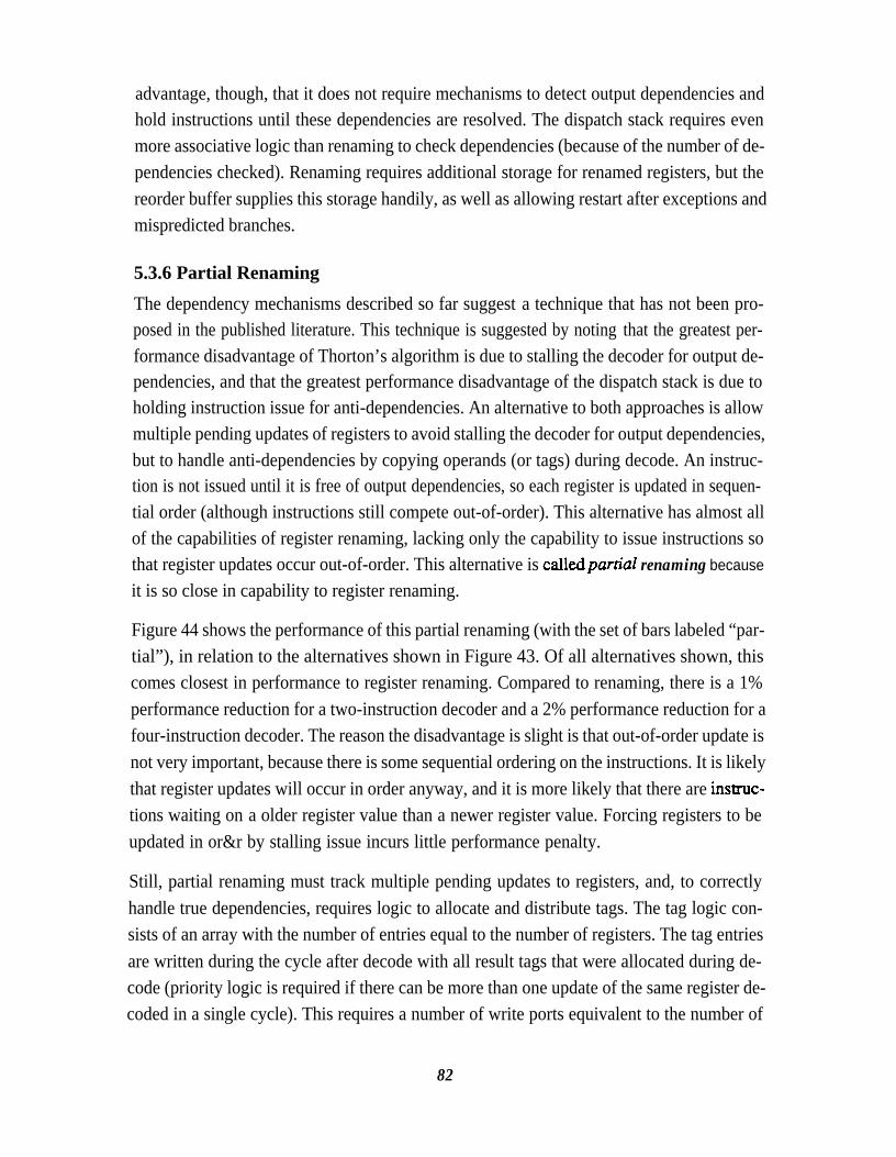
advantage, though, that it does not require mechanisms to detect output dependencies andhold instructions until these dependencies are resolved. The dispatch stack requires evenmore associative logic than renaming to check dependencies (because of the number of de-pendencies checked). Renaming requires additional storage for renamed registers, but thereorder buffer supplies this storage handily, as well as allowing restart after exceptions andmispredicted branches.
5.3.6 Partial Renaming
The dependency mechanisms described so far suggest a technique that has not been pro-posed in the published literature. This technique is suggested by noting that the greatest per-formance disadvantage of Thorton’s algorithm is due to stalling the decoder for output de-pendencies, and that the greatest performance disadvantage of the dispatch stack is due toholding instruction issue for anti-dependencies. An alternative to both approaches is allowmultiple pending updates of registers to avoid stalling the decoder for output dependencies,but to handle anti-dependencies by copying operands (or tags) during decode. An instruc-tion is not issued until it is free of output dependencies, so each register is updated in sequen-tial order (although instructions still compete out-of-order). This alternative has almost allof the capabilities of register renaming, lacking only the capability to issue instructions sothat register updates occur out-of-order. This alternative is calledpartial renaming because
it is so close in capability to register renaming.
Figure 44 shows the performance of this partial renaming (with the set of bars labeled “par-tial”), in relation to the alternatives shown in Figure 43. Of all alternatives shown, thiscomes closest in performance to register renaming. Compared to renaming, there is a 1%performance reduction for a two-instruction decoder and a 2% performance reduction for afour-instruction decoder. The reason the disadvantage is slight is that out-of-order update isnot very important, because there is some sequential ordering on the instructions. It is likelythat register updates will occur in order anyway, and it is more likely that there are insuuc-tions waiting on a older register value than a newer register value. Forcing registers to beupdated in or&r by stalling issue incurs little performance penalty.
Still, partial renaming must track multiple pending updates to registers, and, to correctlyhandle true dependencies, requires logic to allocate and distribute tags. The tag logic con-sists of an array with the number of entries equal to the number of registers. The tag entriesare written during the cycle after decode with all result tags that were allocated during de-code (priority logic is required if there can be more than one update of the same register de-coded in a single cycle). This requires a number of write ports equivalent to the number of
82

SpeduP3
2
1
0
Two-Instruction Decoder
bw h-mean highm = :_ ;I$&:,:\.:.: . . ..i
rename partial nostall norename
SpeeduP Four-Instruction Decoder
bw h-mean highm = ;,,.::‘ii;;::iiii:. . . ,.,. .,.,.,..
rename partial nostall norename
Figure 44. Pelformance Advantage of Partial Renaming
decoded instructions. During decode, the tag array is accessed using operand-register iden-tifiers to obtain tags for operand values, and the tag array is accessed using result-registeridentifiers to obtain tags for the most recent result values. The latter tags are used to delayinstruction issue if there is a pending update to the register, resolving output dependencies.Accessing tags thus requires a number of read ports equal to the number of operands readduring decodeplus the number of results of decoded instructions. Also, delaying instructionissue for output dependencies requires an additional comparator in each reservation-stationentry to detect when a pending update is complete and that the instruction in the reservation-station entry is free of output dependencies.
With a four-instruction decoder, the processor organization described in Section 3.3.2 re-quires a 32-entry tag array (each entry consists of at least a four-bit tag and one valid bit),with four write ports and eight read ports, and 34, four-bit comparators in the reservationstations to implement partial renaming. This hardware is cumbersome, and its object is onlyto avoid associative lookup in the reorder buffer. Since partial renaming has lower perform-ance and requires more hardware than renaming, it has little advantage over renaming with areorder buffer.
83

5.4 Result Buses and ArbitrationFor all results presented so far, two result buses have been used to carry results from the inte-ger and floating-point functional units to the respective reorder buffers. Even at high levelsof performance, the utilization of two result buses is about 50-5596, as illustrated inFigure 45. Figure 45 shows, for various numbers of integer result buses, the average busutilization and average number of waiting results for the sample benchmarks. These resultswere measured for a processor with an average speedup of two. The principle effect of in-creasing the number of buses beyond two is to reduce short-term bus contention, as indicatedby the reduction in the average number of results waiting for a result bus. However, asFigure 46 shows, eliminating this contention completely has a negligible performance bene-fit (less that 1% going from two to three buses).
In the processor model used in this study, the functional units request use of a result bus onecycle in advance of use. An arbiter decides, in any given cycle, which functional units willbe allowed to gate results onto the result buses in the next cycle. There are two separatearbiters-tie for integer results and one for floating-point results. Priority is given for re-sult-bus use to those requests that have been active for more than one cycle, then to requeststhat have become active in the current cycle. The integer functional units are prioritized, indecreasing order of priority, as follows: ALU, shifter, branch (return addresses), loads. The
Fraction of buscapacity utilized
ccom irsim troff yacc
1 2 3 4
Number of Result Buses
Average number of resultswaiting for a result bus
Number of Result Buses
Figure 45. Integer Result-Bus Utilization at High Performance Levels
84

SpeduPTwo-Instruction Decoder Spedup Four-lnstnctiin Decoder
bw h-mean high:. .: .,.::j::
Number of Result Buses
1 2 3 4
Number of Result Buses
Figure 46. Eflect of the Number of Result Buses on Pelformance
floating-point functional units are prioritized as follows: add, multiply, divide, convert. Pri-oritizing old requests over new ones helps prevent starvation, with a slight increase in arbitercomplexity. The arbiter not only decides which functional units are to be granted use of theresult buses, but also which bus is to be used by which functional unit.
If a functional unit requests a result bus but is not granted use, instruction issue is suspendedat that functional unit until the bus is granted. Thus, a functional unit suffers start-up latencyafter experiencing contention for a result bus; this additional latency prevents result busesfrom being 100% utilized even when mote than one result, on the average, is waiting for abus (Figure 45). The advantage of this approach, though, is that functional-unit pipelinestages can be clocked with a common signal, without the complication to the clocking cir-cuitry caused by allowing earlier pipeline stages to operate while later stages are halted.Figure 46 indicates that reducing the effect of bus contention-by adding a third bus-yields a negligible improvement in performance. Hence, reducing the effects of bus conten-tion by more exotic arbitration or additional pipeline buffering is unwarranted
5.5 Result Forwarding
Result forwarding supplies operands that were not available during decode directly to wait-ing instructions in the reservation stations. This resolves true dependencies that could not be
85

resolved during decode. Forwarding avoids the latency caused by writing, then reading theoperand from a storage array, and avoids the additional ports that would be required to allowthe reading of operands both during decode and before issue. Also, as previously discussedin Section 5.3.4, result forwarding simplifies the deallocation of result tags by satisfying allreferences to a tag as soon as the corresponding result is available. Figure 47 shows, for thesample benchmarks, the distribution of the number of operands supplied by forwarding percompleted result. The horizontal axis is a count of the number of reservation-station entriesreceiving the result as an input operand. About two-thirds of all results are forwarded to onewaiting operand, and about one-sixth of all results are forwarded to more than one operand.The high proportion of forwarded results indicates that forwarding is an important means ofsupplying operands.
The primary cost of forwarding is the associative logic in each reservation-station entry todetect, by comparing result tags to operand tags, that a required operand is on a result bus.The processor organization in Section 3.3.2 requires 60, four-bit comparators in the reserva-tion stations to implement forwarding (load instructions have only one register-based oper-and, and the size of the reorder buffer fixes the size of the result tags).
Fractionof Resuttsccom irsim troff yaccm 111
” 0 1 2 3 4 5 6+Number of Operands
Figure 47. Distribution ofNumber of Operands Supplied by Forwarding,Per Result
86

The direct tag search proposed by Weiss and Smith [ 19841 eliminates the associative logicin the reservation stations. In the most general implementation, direct tag search main-tains-for each result tag-a list of operands which are waiting on the corresponding result(Weiss and Smith proposed a single operand rather than a list, but a list is more general, be-cause it allows a result to be forwarded to more than one location). Each operand is identi-fied by the reservation-station location allocated to receive the operand When an instruc-tion depends on an unavailable result, the appropriate reservation-station identifier is placedon the list of waiting operands. If the list is fulI, the decoder stalk. When the result becomesavailable, its tag is used to access the list, and the result is forwarded directly to the waitinginstructions in the reservation stations.
Figure 48 indicates the performance of direct tag search for various numbers of list entries.For best performance, at least three entries are required for each result. Unfortunately, anyimplementation with more than one entry encounters difficulty allocating entries anddetect-ing that the list is full. Furthermore, even an implementation with one list entry requires astorage array for the list table. In the processor described in Section 3.3.2, this table wouldhave sixteen entries of six bits each, with four ports for writing reservation-station identifiersand two ports for reading reservation-station identifiers. There would also be sixty decoding
Speedup3
Two-Instruction Decoder
bw h-mean high
Speedup7
Number of Entries
Four-Instruction Decoder
bw h-mean high
Number of Entries
Figure 48. Pelformance of Direct Tag Searchfor Various Numbers of List Entries
87

circuits to gate the result into the proper reservation-station entry. Direct tag search was pro-posed for a scalar processor and does not save hardware in the super-scalar processor, be-cause of the higher number of instructions decoded and completed per cycle.
In Figure 48, the performance with zero list entries is the performance that would result ifforwarding were not implemented. These results show that the concurrency possible in thesuper-scalar processor does not compensate for the additional latency caused by a lack offorwarding, further illustrating the value of fonvatding.
Forwarding not only takes a large amount of hardware, but also creates long critical &laypaths. Once a result is valid on a result bus, it is necessary to detect that this is a requiredresult, and gate the result to the input of the functional unit so that the functional unit canbegin operation as the result is written into the reorder buffer. To avoid having the forward-ing delay appear as part of the functional-unit delay, and to allow data paths to be set up intime, the actual tag comparison should be performed at the end of the cycle preceding resultavailability. This in turn implies that the tags for the two results should appear on the tagbuses a cycle before the results appear on the result buses. Providing result tags early is diffi-cult, because it requires that result-bus arbitration be performed very early in the cycle.
5.6 Implementing Renaming with a Reorder Buffer
Previous sections have argued that a reorder buffer should be used to implement restartingand renaming, and have argued that forwarding is required to sustain performance. This sec-tion considers, in detail, a straightforward implementation of the instruction decoder, reor-der buffer, reservation stations, and forwarding logic in light of the requirements of registerrenaming, operand routing, and restart. A four-instruction decoder is described, but thechanges necessary for a two-instruction decoder should be obvious. The implementationpresented here provides a good illustration of the hardware complexity, showing that thebest alternative is quite complex.
5.6.1 Allocating Processor Resources
During instruction decode, the processor allocates result tags, reorder-buffer entries, andreservation-station entries to the instructions being decoded. Allocation is accomplished byproviding instructions with identifiers for these resources, using the hardware organizationshown in Figure 49. Hardware similar to that shown in Figure 49 is used for each resource tobe allocated; for example, a version of this hardware is required for each reservation station,to allocate entries to instructions.
88
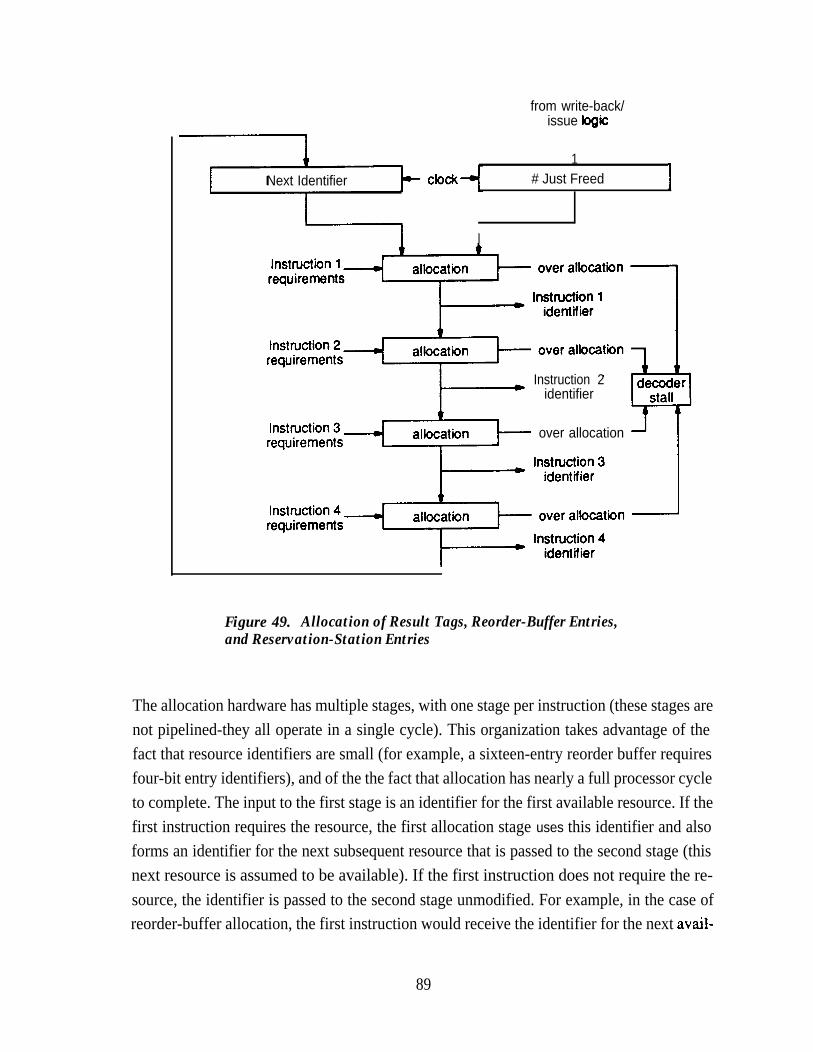
Next Identifier
from write-back/issue logic
1clock # Just Freed I
I
Instruction 2identifier
over allocation
Figure 49. Allocation of Result Tags, Reorder-Buffer Entries,and Reservation-Station Entries
The allocation hardware has multiple stages, with one stage per instruction (these stages arenot pipelined-they all operate in a single cycle). This organization takes advantage of thefact that resource identifiers are small (for example, a sixteen-entry reorder buffer requiresfour-bit entry identifiers), and of the the fact that allocation has nearly a full processor cycleto complete. The input to the first stage is an identifier for the first available resource. If thefirst instruction requires the resource, the first allocation stage uses this identifier and alsoforms an identifier for the next subsequent resource that is passed to the second stage (thisnext resource is assumed to be available). If the first instruction does not require the re-source, the identifier is passed to the second stage unmodified. For example, in the case ofreorder-buffer allocation, the first instruction would receive the identifier for the next avail-
89
able reorder-buffer entry, and the second instruction would receive the identifier for the sec-ond available reorder-buffer entry.
The identifier for the frost available resource is based upon the resources allocated and freedin the previous cycle. For example, again in the case of reorder-buffer allocation, assumethat the fifth reorder-buffer entry were allocated to the final instruction in the previous de-code stage, and that two reorder-buffer entries were written into the register file (thus freed).The first valid instruction in the next decode cycle would be allocated the fourth entry (thepreviously-allocated entries are moved up two locations at the end of the same cycle), andother instructions would be allocated the fifth and subsequent entries.
Each allocation stage--other than the first one-is essentially an incrementer for resourceidentifiers. The stage either increments the identifier or passes it unmodified, depending onthe needs of the corresponding instruction. If any incrementer attempts to allocate beyondthe last available resource, the decoder is stalled, and the associated instruction (and all sub-sequent instructions) repeat the decode process on the next cycle. Note that the incrementersneed not generate identifiers in numerical sequence, because the identifiers are used by hard-ware alone. The identifiers can be defined so that the incrementers take minimal logic.
In this implementation, there is separate hardware to allocate result tags for instructions.Reorder-buffer identifiers are inappropriate to use as result tags, because these identifiersare not unique. Reorder-buffer entries are allocated at the end of a FIFO, and it is likely thatthe same entries will be allocated over several decode cycles. However, the result tags havethe same number of bits as reorder-buffer identifiers, because both track pending updates.
5.6.2 Instruction Decode
During instruction decode, the dependency logic must insure that all instructions receive op-erands or tags. In addition, the state of the dependency logic must be updated so that subse-quent instructions obtain operands correctly. Figure 50 illustrates some of the dependencyoperations performed during instruction decode, focusing on the operations performed onthe reorder buffer.
To obtain operands, the reorder buffer is searched associatively using the source-registeridentifiers of the decoded instructions. These source-register identifiers are compared toresult-register identifiers stored in the reorder buffer, at each of four read ports. If the resultis not available, a result tag is obtained. As Figure 50 shows, result tags use the same storageas result values, so that operand values and tags are treated uniformly and use the same buses
90

Instruction Decode,Reorder Buffer Allocation,
Tag Allocation,Reservation Station Allocation,
result-register I I I I
identifiers
I*11Reorder Buffer
Reg# 1Reg# 1
reorderident
I II I I of r-4 ! Tag
ferwfiers
El Reg # Result ValueReg # Result Valuem-- a,
OPOPOP
4 i 4 + + + 4 +Tag Operand Value Tag \
Operand Value Tag TagTag Tag Tag
register-operand
buses
,eservation-station
identifiers1 OP I Operand Value I Operand Value 1 Tag1/
Reservation Station
Figure 50. Instruction Decode Stage
for distribution. This minor optimization does not handle all requirements for tag distribu-tion, as discussed below. If instructions arbitrate for operand buses, as assumed here, thereservation stations must match instructions to operands or tags, so that these can be storedproperly.
Supplying operands to reservation stations requires two paths that are not shown inFigure 50 (these are omitted for clarity). The first of these paths distributes instruction-im-mediate data from the decoder to the reservation stations. The second path distributes tagsfor instructions that depend on instructions which are decoded in the same cycle. These tags
91

are supplied by the tag-allocation hardware, rather than the reorder buffer. If the instructionformat explicitly identifies instruction dependencies, such as that described in Section 4.4.2,the decoder can easily distribute the appropriate tags. Otherwise, this must be based on com-parisons between destination-register and source-register identifiers of decoded instruc-tions, taking twelve comparators. In either case, the dependent operands am not allocatedoperand buses, requiring other buses to distribute tags to the reservation stations.
There is a potential pipeline hazard in the forwarding logic Weiss and Smith 19841 that thedesign must avoid. This hazard arises when a decoded instruction obtains a result tag atabout the same time that the result is written. In this case, it is possible that the forwardinglogic obtains a result tag, but misses the write-back of the corresponding result, causing in-correct operation. Avoiding this hazard may may take eight additional comparators to de-tect, during decode, that forwarding is required in the next cycle.
At the end of the decode cycle, the result-register identifiers and result tags for decoded in-structions are written into the reorder buffer. These should be written into the empty loca-tions nearest the head of the buffer, as identified by the allocation hardware. This requiresfour write ports on the storage for register identifiers and tags at each location of the reorderbuffer. The four write ports could be avoided by allocating entries only at the tail of the reor-der buffer, in which case only these entries would require four write ports. However, allocat-ing entries at the tail of the reorder buffer complicates the associative lookup, because it be-comes difficult to determine the location of valid entries. Furthermore, this approach in-creases the amount of time taken for a result to reach the head of the reorder buffer, increas-ing the branch delay if the entire reorder buffer is flushed on a mispredicted branch as dis-cussed in Section 5.2.1.
With respect to updating the dependency logic, renaming and partial renaming with a futurefile also require four ports for writing tags into a tag array. The reorder buffer has the advan-tage that it is generally smaller than the register file, and takes fewer write decoders. In theexample described here, the reorder buffer has half the number of entries of the register file.
5.6.3 Instruction Completion
When a functional unit generates an instruction result, the result is written into the reorderbuffer after the reservation station has successfully arbitrated for the result bus. The resulttag must be used to identify which reorder-buffer entry is to be written. The reorder-bufferidentifier that was allocated during decode was used only to write the result tag and the re-sult-register identifier into the reorder buffer, and is meaningless in subsequent cycles
92

because entries advance through the reorder buffer as results are written to the register file.Thus, this write must be associative: the written entry is the one with a result tag that matchesthe result tag of the completed instruction. This is true of any reorder buffer operated as aFIFO, with or without a future file.
5.7 Observations and Conclusions
Instruction restart is an integral part of the super-scalar processor, because it allows instruc-tion decoding to proceed at a high rate. Even the software approaches to improving the fetchefficiency proposed in Section 4.2.4 require nullifying the effect of a variable number of in-structions. Furthermore, there is little sense in designing a super-scalar processor with in-or-der completion, because of the detrimental effect on instruction-level concurrency. Restart-ing a processor with out-of-order completion requires at least some of the hardware de-scribed in this chapter. If out-of-order issue is implemented, the reorder buffer provides avery useful means for recovering the instruction sequentiality that is given up after decode;for example, it helps in committing stores to the data cache at the proper times. Finally, thebuffering provided for restart, with associative lookup, helps manage the look-ahead stateand simplifies operand dependency analysis.
The best implementation of hardware restart has either a twelve-entry or a sixteen-entry re-order buffer, with every instruction being allocated an entry in this buffer. A future file pro-vides a way to avoid associative lookup in the reorder buffer, at the prohibitive cost of anadditional register array. The future file also adds delay penalties to mispredicted branches,because it requires that the processor state be serialized up to the point of the branch beforeinstruction execution resumes.
If software alone cannot insure the absence of dependencies, renaming with a reorder bufferis the best hardware alternative for resolving operand dependencies. Unfortunately, de-pendency analysis is fundamentally hard, especially when multiple instructions are in-volved. All of the alternatives to renaming explored in this chapter require a comparable orgreater amount of hardware, with reduced performance. The example implementation ofrenaming presented in this chapter takes: 64, five-bit comparators in reorder buffer for read-ing operands; 32, four-bit comparators in reorder buffer for writing results; 60, four-bit com-parators in reservation stations for forwarding; logic for allocating result tags and reorder-buffer entries; and a four-read-port, two-write-port reorder buffer that has four additionalwrite ports on portions of the entries for writing register identifiers, results tags, and instruc-tion state. The complexity of this hardware is set by the number of uncompleted instructions
93

permitted, the width of the decoder, the requirement to restart after a mispredicted branch,and the requirement to forward results to waiting instructions.
The associative logic and multiple-port arrays are unattractive, but are not easily eliminated.Without the associative logic for forwarding, the super-scalar processor has worse perform-ance than a scalar processor. Adding a future file to the architecture can eliminate the asso-ciative read in the reorder buffer, but a future file also requires tag comparisons in the write-back logic to implement renaming and incurs the cost of the future file itself. The tag com-parisons in the write-back logic can be eliminated by partial renaming (which updates regis-ters in order), but the logic to guarantee that registers are updated in order is more complexthan the eliminated logic. Thorton’s algorithm can be used with a future file to eliminate theassociative lookup in the reorder buffer, and does not require tag-comparison logic to writeresults into the future file. However, Thor-ton’s algorithm yields the poorest performance ofany alternative explored in this chapter, and requires a technique for detecting during decodethat result registers have pending updates. Considering also the cost of the four-write-port,two-read-port tag array for the future file, any approach using a future file holds little prom-ise.
The cost of the dependency and forwarding hardware should be viewed as a more-or-lessfixed cost of attaining a high instruction-execution rate. Of course, this can lead to the con-clusion that such an instruction-execution rate is too ambitious. The argument offered hereis only that there are no simple hardware alternatives yet discovered that yield correct opera-tion with performance better than in-order issue. The following chapter considers otherways to reduce the amount of hardware required, by focusing on alternatives to reservationstations.
94

Chapter 6Instruction Scheduling and Issuing
The peak instruction-execution rate of a super-scalar processor can be almost twice the aver-age instruction-execution rate, as shown in Figure 6 (page 27). This is in contrast to a scalarFUSCprocessor, which typically has an average execution rate that is within 30% of the peakrate. A straightforward approach to super-scalar processor design is to simply provideenough hardware to support the peak instruction-execution rate. However, this hardware isexpensive, and the difference between the average and peak execution rates implies that thehardware is under-utilized.
A more cost-effective approach to processor design is to carefully constrain the hardware inlight of the average instruction-execution rate. Several examples of this approach have beenseen in preceding chapters. Chapter 4 demonstrated that the number of register-ftie readports could be constrained to four-approximately the number of ports needed to sustain anexecution rate of two instruction per cycle-even with a four-instruction decoder. Simi-larly, Chapter 5 demonstrated that the tag logic associated with the register file inTomasulo’s algorithm can be consolidated into a reorder buffer that requires less tag hard-ware than the register file because it tracks only pending register updates.
The reservation stations described in Table 3 (page 32) are also under-utilized. These reser-vation stations-used to obtain all results so far-have a total capacity of thirty-four instruc-tions. However, Chapter 5 showed that the reorder buffer should have twelve to sixteen lo-cations. Since the total allocation for the reorder buffer is determined by instructions in thewindow and in the pipeline stages of the functional units, this indicates that the instructionwindow contains fewer than about twelve instructions.
The problem of under-utilization of the reservation stations is overcome by consolidatingthem into a smaller central window. The central window holds all unissued instructions,regardless of the functional units required by the instructions, as illustrated by Figure 51(only the integer functional units are shown in Figure 51, and the central window may beduplicated in the floating-point unit, depending on the implementation). For a given level ofperformance, the central window uses much less storage than reservation stations, less con-trol hardware, and less logic for resolving dependencies and forwarding results.
This chapter presents the motivations for the reservation-station sizes given in Table 3, thenexamines two published central-window proposals in an attempt to reduce hardware
95

t1 I I 1 I I
Instruction I ICache
Register Reorder
I
File Buffer
I
LDecoder I
II t
1
t t- Central= W in&w
I I I
I
Branch
I 1 1 It
Shifter Load storeALU
1 I4
Figure 51. Location of Central Window in Processor (Integer Unit)
requirements: the dispatch stuck proposed by Tomg [ 19841 and the register update unit ofSohi and Vajapeyam [ 19871. Both of these proposals have disadvantages: the dispatch stackis complex, and the register update unit has relatively poor performance. In both proposals,the disadvantages are the result of using the central window to implement operations that arebetter implemented by the reorder buffer. A third proposal presented in this chapter relies onthe existence of the reorder buffer and associated dependency logic to simplify the centralwindow. This serves as an additional illustration of the synergy between hardware compo-nents in the super-scalar processor.
96

The second major topic of this chapter is the implementation of loads and stores with a cen-tral instruction window. This chapter demonstrates how load and store hardware can be sim-plified, in a processor that uses a central window to issue instructions. However, it should benoted that the benchmark programs used in this study do not have a high frequency of loadsand stores compared to many scientific applications, and thus the performance of thesebenchmark programs is not very sensitive to limitations in the data-memory interface.
6.1 Reservation Stations
Reservation stations partition the instruction window by functional unit, as shown inFigure 7 (page 29). This partition helps simplify to control logic at each reservation station,but causes total number of reservation-station entries to be much larger than required for acentral instruction window.
6.1.1 Reservation Station Operation
A reservation-station entry holds a decoded instruction until it is free of dependencies andthe associated functional unit is free to execute the instruction. The following steps are takento issue instructions from a reservation station:
1) Identify entries containing instructions ready for issue. An instruction isready when it is the result of a valid decode cycle, and all operands arevalid. Operands may have been valid during decode, or may have just be-come valid because a result has been computed.
2) If more than one instruction is ready for issue, select an instruction for is-sue among the ready instructions.
3) Issue the selected instruction to the functional unit.
4) Deallocate the reservation-station entry containing the issued instruction,so that this entry may receive a new instruction. For best utilization of thereservation station, the entry should be able to receive an instruction fromthe decoder in the next cycle.
These functions are performed in any instruction window that implements out-of-order is-sue. Reservation stations have some advantage, though, in that these functions are parti-tioned and distributed in a way that simplifies the control logic. Most reservation stationsperform these functions on a small number of instructions. The load and store reservationstations are relatively large (eight entries each), but these reservation stations are con-strained to issue instructions in order, and so there is only one instruction that can be
97
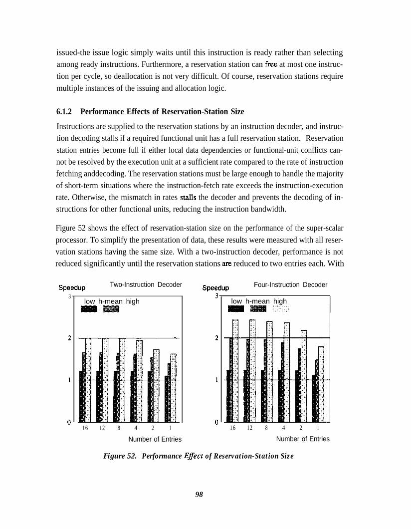
issued-the issue logic simply waits until this instruction is ready rather than selectingamong ready instructions. Furthermore, a reservation station can free at most one instruc-tion per cycle, so deallocation is not very difficult. Of course, reservation stations requiremultiple instances of the issuing and allocation logic.
6.1.2 Performance Effects of Reservation-Station Size
Instructions are supplied to the reservation stations by an instruction decoder, and instruc-tion decoding stalls if a required functional unit has a full reservation station. Reservationstation entries become full if either local data dependencies or functional-unit conflicts can-not be resolved by the execution unit at a sufficient rate compared to the rate of instructionfetching anddecoding. The reservation stations must be large enough to handle the majorityof short-term situations where the instruction-fetch rate exceeds the instruction-executionrate. Otherwise, the mismatch in rates stalk the decoder and prevents the decoding of in-structions for other functional units, reducing the instruction bandwidth.
Figure 52 shows the effect of reservation-station size on the performance of the super-scalarprocessor. To simplify the presentation of data, these results were measured with all reser-vation stations having the same size. With a two-instruction decoder, performance is notreduced significantly until the reservation stations are reduced to two entries each. With
Speedup3
Two-Instruction Decoder
low h-mean high
Speedup
16 12 8 4 2 1
Number of Entries
Four-Instruction Decoder
low h-mean high
16 12 8 4 2 1
Number of Entries
Figure 52. Performance E#ect of Reservation-Station Size
98
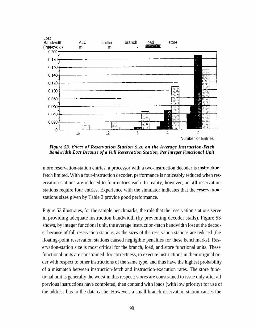
LostBandwidth ALU shifter branch load store(insffcycle) m m - .
0.200 , I
16 12 8 4 2Number of Entries
Figure 53. Efect of Reservation Station Size on the Average Instruction-FetchBandwidth Lost Because of a Full Reservation Station, Per Integer Functional Unit
more reservation-station entries, a processor with a two-instruction decoder is instruction-fetch limited. With a four-instruction decoder, performance is noticeably reduced when res-ervation stations are reduced to four entries each. In reality, however, not ail reservationstations require four entries. Experience with the simulator indicates that the reservation-stations sizes given by Table 3 provide good performance.
Figure 53 illustrates, for the sample benchmarks, the role that the reservation stations servein providing adequate instruction bandwidth (by preventing decoder stalls). Figure 53shows, by integer functional unit, the average instruction-fetch bandwidth lost at the decod-er because of full reservation stations, as the sizes of the reservation stations are reduced (thefloating-point reservation stations caused negligible penalties for these benchmarks). Res-ervation-station size is most critical for the branch, load, and store functional units. Thesefunctional units are constrained, for correctness, to execute instructions in their original or-der with respect to other instructions of the same type, and thus have the highest probabilityof a mismatch between instruction-fetch and instruction-execution rates. The store func-tional unit is generally the worst in this respect: stores are constrained to issue only after allprevious instructions have completed, then contend with loads (with low priority) for use ofthe address bus to the data cache. However, a small branch reservation station causes the
99

most severe instruction-bandwidth limitation, because branches are more frequent thanstores and because branches are likely to depend on the results of a series of instructions (thisdependency is the reason that the branch delay is typically three or four cycles).
Reservation stations are under-utilized because they serve two purposes: they implement theinstruction window (requiring buffering for less than sixteen instructions), and they preventlocal demands on a functional unit from stalling the decoder (taking two to eight entries ateach functional unit, for a total of thirty-four entries). The latter consideration is most im-portant for the branch, load, and store functional units, but causes the total number of reser-vation-station entries for all functional units to be higher than the number required solely forthe instruction window.
6.2 Central Instruction Window
As stated previously, a central window is a more efficient implementation of the instructionwindow than reservation stations, because it holds all instructions for issue regardless offunctional-unit requirements. The central window consolidates all instruction-window en-tries and scheduling logic into a single structure. However, the scheduling logic associatedwith a central window is more complex than the corresponding logic in a reservation station,for several reasons:
l The central window selects among a larger number of instructions than doesa reservation station. The central window schedules all instructions in thewindow, rather than a subset of these instructions as is the case with a reser-vation station.
l The central window must consider functional-unit requirements in selectingamong ready instructions.
l The central window can free more than one entry per cycle, so allocation anddeallocation are more complex than with reservation stations.
This section explores two implementations of a central window-the dispatch stack [Tomg19841 and the register update unit [Sohi and Vajapeyam 1987]-and proposes a third imple-mentation that has much better performance than the register update unit without the com-plexity of the dispatch stack. The proposed implementation relies on the dependency logicdescribed in Chapter 5, and thus relies on the existence of a reorder buffer, whereas the dis-patch stack and register update unit incorporate some of the function of the reorder buffer.However, the reorder buffer is an important component for supporting branch prediction and
100
register renaming: the fact that the reorder buffer can simplify the central window is a furtheradvantage of the reorder buffer.
It is also shown in this section that the number of buses requited to distribute operands from acentral window is comparable to the number of buses required to distribute operands to res-ervation stations-negating the concerns expressed in Section 3.3.1. The central windowcan schedule instruction issue around the operand-bus limitation, illustrating that the in-struction window allows execution hardware to be constrained without much reduction inperformance. However, arbitrating for operand buses further complicates the schedulinglogic associated with the central window.
6.2.1 The Dispatch Stack
In every cycle, the dispatch stack [Tomg 1984, Acosta et al. 1986, Dwyer and Tomg 19871performs operations that are very similar to those performed in a reservation station:
1) Identify entries containing instructions ready for issue.
2) Select instructions for issue among the ready instructions, based on func-tional-unit requirements. This involves prioritizing among instructionsthat require the same functional unit.
3) Issue the selected instructions to the appropriate functional units.
4) Deallocate the reservation-station entries containing the issued instruc-tions, so that these entries may receive new instructions.
The dispatch stack keeps instructions in a queue sorted by order of age, to simplify depend-ency analysis (dependencies are resolved in the dispatch-stack proposal by usage and defini-tion counts, as described in Section 2.3.4) and to simplify prioritizing among ready instruc-tions (it is easy to give priority to older instructions because these are nearer the front of thestack). To keep instructions in order, the dispatch stack cannot just allocate entries by plac-ing decoded instructions into freed locations: it must fill these locations with older, waitinginstructions and allocate entries for new instructions at the end of the stack, as shown inFigure 54.
Figure 55 shows the effect of dispatch-stack size on the performance of the super-scalarprocessor. This performance was measured with a dispatch stack that can accept a portion ofthe decoded instructions when the stack does not have enough entries for all decoded in-structions. Also, an instruction can remain in the dispatch stack for an arbitrary amount oftime. Both a two-instruction and a four-instruction decoder decoder require only an eight-
101

Before ism: &$gu:
Decoder Decoder
Dispatch Stack
16 - issue
I4 -----emm--e-
---eml L-------.
- issue l - - - - - - - - -
Figure 54. Compressing the Dispatch Stack
Speedup3
Two-Instruction Decoder
low h-mean high
16 12 8 4 2
Speedup
Number of Entries Number of Entries
Four-Instruction Decoder
low h-mean high.‘.
16 12 8 4 2
Figure 55. Performance Effect of Dispatch-Stack Size
102

I
entry dispatch stack for best performance. This is consistent with the size expected from thesize of the reorder buffer. Thus, with a four-instruction decoder, the dispatch stack usesabout one-fourth of the storage and forwarding logic of the reservation stations. Further-more, the instruction-scheduling logic is not duplicated (unless it is duplicated in separateinteger and floating-point units). With the reservation stations in Table 3, the instruction-is-sue logic is replicated ten times.
Unfortunately, instruction scheduling with a dispatch stack is complex, because the dispatchstack keeps instructions in order. Compressing and allocating the window can occur onlyafter the window has identified the number and location of the instructions for issue. Com-pressing the window also requires that any entry be able to receive the contents of any subse-quent (newer) entry and that the entries for the newest instructions be able to receive the in-struction from any decoder slot. Thus, for example, an entry in an eight-location windowwith a four-instruction decoder requires a maximum of eleven possible input sources, aminimum of four, and an average of about eight. Dwyer and Tomg [ 19871 estimate that theissue, compression, and allocation logic for a proposed implementation of an eight-entrycentral window consume 30,000 gates and 150,O transistors.
6.2.2 The Register Update UnitAlthough a dispatch stack requires less storage for instructions and operands than do reser-vation stations, the complexity of the issue, compression, and allocation hardware in a dis-patch stack argues against its use. The register update unit [Sohi and Vajapeyam 19871 is asimpler implementation of a central window that avoids the complexity of compressing thewindow before allocation.
The operations performed to issue instructions in the register update unit are identical tothose in the dispatch stack (the criteria for issue are different, though, because the depend-ency mechanism is different). However, the register update unit allocates and frees windowentries in a first-in, first-out (FIFO) manner, as shown in Figure 56. Instructions are enteredat the tail of the FIFO, and window entries are kept in sequential order. An entry is not re-moved when the associated instruction is issued. Rather, an entry is removed when itreaches the head of the FIFO, When an entry is removed, its result (if applicable) is writtento the register file. This method was originally proposed to aid the implementation of pre-cise interrupts, but it also decouples instruction issuing from window allocation and uses asimple algorithm to allocate window entries.
Figure 57 shows the performance of the register update unit, as a function of size. The set ofbars in the foreground of Figure 57 show the speedup obtained with a register update unit,
103

B e f o r e - : i-:After
Decoder DecoderI l l110I9I8 - - - - - - - - - - - - -
1Register Update UnitI 1
[- I9 1
Register Update UnitI I
I7I6I5I4I3I2I1IO
- - - - - - - - - - - L-1
- issue -----1m--------ml ,:z:-----e--e1 L----m’
- issue --1 Lm---m
- issue -1 L- - - - - -----mel L - - - - - - - c
- issue L--e----m
I8I7WI5I4
(13)(12)I1
Figure 56. Register Update Unit Managed as a FIFO
Speedup Two-Instruction Decoder
low h-mean [email protected]
16 12 8 4 2
Number of Entries
Speedup
low h-mean high: .:
16 12 8 4 2
Number of Entries
Figure 57. Pe@ormance Degradation of Register Update UnitCompared to Dispatch Stack
104

and the set of bars in the background repeat the data for the dispatch stack, from Figure 55,for comparison. For all sizes shown, performance of the register update unit is significantlylower than the performance of a dispatch stack of equal size. The performance disadvantageis most pronounced for smaller window sizes (the reason performance can be lower than thatof the scalar processor is that instructions remain in the register update unit for at least onecycle before being written to the register file, possibly stalling the decoder for longer periodsthan if results are written directly to the register file). Sohi and Vajapeyam [ 19871 reportsimilar results-they find that a fifty-entry register update unit provides the best perform-ance, in a processor that has higher functional-unit latencies that the processor used in thecurrent study.
There are two reasons that the register update unit has this performance disadvantage(Figure 56 helps to illustrate these points):
l Window entries are used for instructions which have been issued.
l Instructions cannot remain in the window for an arbitrary amount of timewithout reducing performance. Rather, the decoder stalls if an instructionhas not been issued when it reaches the head of the register update unit.
Figure 58 shows, for the dispatch stack described in Section 6.2.1, the average distributionof the number of cycles from instruction decode to instruction issue. With the register up-date unit, instructions at the high end of this distribution stall the decoder, because they can-not be issued and complete by the time they arrive at the front of the window. As discussedinSection 6.1.2, stores experience the worst decode-to-issue delay, because they can be issuedin order only after all previous instructions are complete and then contend with loads for thedata cache.
It should be emphasized that Sohi and Vajapeyam [ 19871 proposed the register update unitas a mechanism for implementing precise interrupts and restarting after mispredictedbranches. The disadvantages cited here are due to the different objective of reducing the sizeof the instruction window.
6.2.3 Using the Reorder Buffer to Simplify the Central Window
Both the complexity of the dispatch stack and the relatively low performance of the registerupdate unit can be traced to a common cause: both proposals attempt to maintain instruc-tions ordered in the central window. However, a reorder buffer is much better suited tomaintaining instruction-ordering information. The reorder buffer is not compressed as is the
105

Fraction of Issue ALU shifter branchCycles mm
”
1 2 3 4 5 6 7 8+Decode-to-IssueDelay (cycles)
Figure 58. Distribution of Decode-to-Issue Delay for Various Functional Units
dispatch stack, and the deallocation of reorder-buffer entries is not in the critical path of in-struction issue. Rather, reorder-buffer entries are allocated at the tail of a FIFO and dealloca-tion occurs as results are written to the register file. Also, in contrast to the register updateunit, instructions will not stall the instruction decoder if they are not issued by the time thecorresponding entry reaches the head of the reorder buffer. As described in Section 5.2.2,for example, stores are simply released for issue at the output of the reorder buffer. Severalstores can be released in a single cycle, so the reorder buffer does not suffer the single-issueconstraints of a store in the register update unit. Consequently, the reorder buffer does notstall instruction decoding as readily as the register update unit. The different method forhandling stores is the primary advantage of this approach over the register update unit.
In an implementation with a reorder buffer, then, there is no real need to keep instructionsordered in the central window. The window is not compressed as instructions are issued.Instead, new instructions from the decoder are simply placed into the freed locations, asFigure 59 shows. The principal disadvantage of this approach is that there is no instruction-ordering information in the instruction window, and it is not possible to prioritize instruc-tions for issue based on this order. In general, when two instructions are ready for issue at thesame time and require the same functional unit, it is better to issue the older instruction,
106

Beforeiu:
Decoder
Central Window
issue
issue
Decoder
Central WindowI7I l lI5I4110
1 L-----w I9
L,-----.dI1I8
Figure 59. Allocating Window Locations without Compressing
Two-Instruction Decoder Speedup Four-Instruction Decoder
low h-mean hiQh
16 12 8 4 2Number of Entries
low h-mean high
16 12 8 4 2Number of Entries
Figure 60. Pe@ormance Effect of Central-Window Size without Compression
107

because this is more likely to free other instructions for issue. Still, the data in Figure 60suggest that this is not a very important consideration. Figure 60 gives performance as func-tion of central-window size when the window is allocated without compression as shown inFigure 59. In this configuration, instructions are prioritized for issue based on their positionin the central window, but this position has nothing to do with the original program order.Compared to the performance of the dispatch stack, the reduction in performance caused bythis less-optimal prioritization is less than 1% for any benchmark-the reduction is less thanthe measurement precision for most benchmarks. Obviously, the dependencies between in-structions are sufficient to prioritize instruction issue.
Even though instructions do not have to be ordered in the window for performance, someinstructions (loads, stores, and branches) must be issued in original program order. The cen-tral window proposed here does not preserve instruction ordering, and thus complicates is-suing instruction in order. This difficulty is easily overcome by allocating sequencing tagsto these instructions during decode if there is another, unissued instruction of the same typein the window. When a sequenced instruction is issued, it transmits its tag to all windowentries, and the window entry with a matching sequencing tag is released for issue.
6.2.4 Operand Buses
A concern with a central window is the amount of global (chip-wide) interconnection re-quired to supply operands to the functional units from the central window. The process ofdistributing instructions and operands is significantly different for acentral window than it isfor reservations stations. Instructions and operands are placed into the central window usinglocal interconnections from the decoder, reorder buffer, and register file. The window inturn issues these instructions and operands to the functional units using globai interconnec-tions. In contrast, instructions and operands are placed into reservation stations using globalinterconnections. The reservation stations in turn issue these instructions and operands tothe functional units using local interconnections.
Section 4.4 established that a limit of four register-based operands is sufficient to supply res-ervation stations, and does not significantly reduce performance. This gives an estimate ofthe number of interconnection buses required for the distribution of instructions and oper-ands to reservations stations. However, this number of operands is sufficient because emptydecoder slots and dependencies between decoded instructions reduce the demand on regis-ter-based operands during decode. If instructions and operands are issued to the functional
108
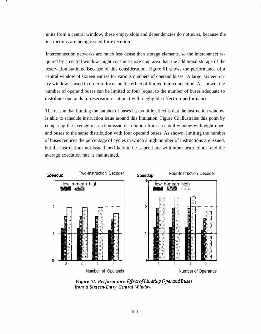
I
units from a central window, these empty slots and dependencies do not exist, because theinstructions are being issued for execution.
Interconnection networks are much less dense than storage elements, so the interconnect re-quired by a central window might consume more chip area than the additional storage of thereservation stations. Because of this consideration, Figure 61 shows the performance of acentral window of sixteen entries for various numbers of operand buses. A large, sixteen-en-try window is used in order to focus on the effect of limited interconnection. As shown, thenumber of operand buses can be limited to four (equal to the number of buses adequate todistribute operands to reservation stations) with negligible effect on performance.
The reason that limiting the number of buses has so little effect is that the instruction windowis able to schedule instruction issue around this limitation. Figure 62 illustrates this point bycomparing the average instruction-issue distribution from a central window with eight oper-and buses to the same distribution with four operand buses. As shown, limiting the numberof buses reduces the percentage of cycles in which a high number of instructions are issued,but the instructions not issued am likely to be issued later with other instructions, and theaverage execution rate is maintained.
Speedup3
Two-Instruction Decoder
low h-mean high
8 6 4 2
Speedup
Number of Operands Number of Operands
Four-Instruction Decoder
low h-mean high
8 6 4 2
Figure 61. Performance EflectofLimiting OperandBusesfrom a Sixteen-Entry Central Window
109

Fraction ofTotal Cycles
eight buses four buses.A.::\. ..,.
4 5Number of Instructions
Figure 62. Change in Average Instruction-Issue Distribution fromSixteen-Entry Central Window as Operand Buses are Limited
6.2.5 Central Window Implementation
The primary difficulty of operand distribution with the central window is not that too manybuses are required, but the fact that operand-bus arbitration must be considered during in-struction scheduling. The arbitration for operand buses is conceptually similar to the regis-ter-port arbiter discussed in Section 4.4.1, except that there are as many as sixteen operandscontending for the four shared buses. Furthermore, it is more difficult to determine which ofthe contenders are actually able to use the buses. For example, to determine which instruc-tions are allowed to use operand buses, it is first necessary to determine which instructionsare ready to be issued and which functional units are ready to accept new instructions. Fol-lowing this, functional-unit conflicts among ready instructions must be resolved before in-structions arbitrate for operand buses. Fortunately, there is somewhat more time to accom-plish these operations than there is with register-port arbitration, because register-point arbi-tration typically must be completed by the mid-point of a processor cycle.
The longest identifiable path in the instruction-scheduling logic arises when an instruction isabout to be made ready by a result that will be forwarded. In this case, the result tag is validthe cycle before the result is valid, and a tag comparison in the instruction window readiesthe instruction for issue. Once the scheduling logic determines that the instruction is ready,
110

the instruction participates in functional-unit arbitration, then operand-bus arbitration. If theinstruction can be issued, the location it occupies is made available for allocation to a de-coded instruction. Table 5 gives an estimate of the number of stages required for each ofthese operations, using serial arbitration as described in Section 5.6.1 for the complex arbi-ters and assuming no special circuit structures (such as wired logic). The sixteen stages re-quired are within the capabilities of most technologies.
It is interesting to note that four of the operations in Table 5 are concerned with resourcearbitration and allocation. That these operations have also been examined within the con-texts of instruction fetching and dependency analysis suggests that hardware structums forarbitration and allocation are important areas for detailed investigation. Sustaining an in-s,truction throughput of more than one instruction per cycle with a reasonably small amountof hardware creates many situations where multiple operations are contending for multiple,shared resources. The speed and complexity of the hardware for resolving resource conten-tion is easily as important as any other implementation consideration addressed in this study,but it is impossible to determine the feasibility of this hardware without knowing preciselythe details of the implementation.
Despite its additional complexity, the central window is preferred over reservation stations.It uses many fewer storage locations and comparators for forwarding than do reservationstations, and requires comparable busing to distribute operands.
6.3 Loads and StoresGenerally, it is not possible to improve concurrency of loads and stores by issuing them out-of-order, except that loads can be issued out-of-order with respect to stores if each load
Table 5. Critical Path for Central-Window Scheduling
Function in Path Number of Stages
result-bus arbitration 2
drive tag buses 1
compare results tags to operand tags and determine ready instructions 3
functional-unit arbitration
operand-bus arbitration
allocate free window entries to decoded instructions
2
4
4
TOTAL: 16
111
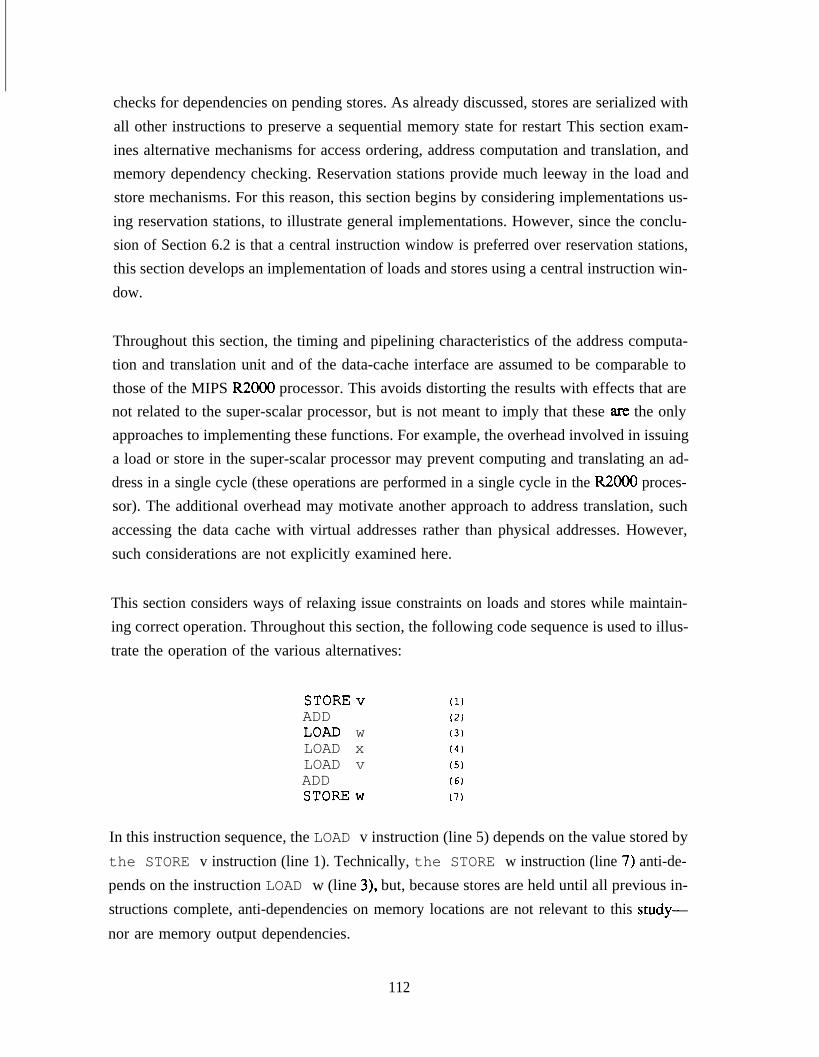
checks for dependencies on pending stores. As already discussed, stores are serialized withall other instructions to preserve a sequential memory state for restart This section exam-ines alternative mechanisms for access ordering, address computation and translation, andmemory dependency checking. Reservation stations provide much leeway in the load andstore mechanisms. For this reason, this section begins by considering implementations us-ing reservation stations, to illustrate general implementations. However, since the conclu-sion of Section 6.2 is that a central instruction window is preferred over reservation stations,this section develops an implementation of loads and stores using a central instruction win-dow.
Throughout this section, the timing and pipelining characteristics of the address computa-tion and translation unit and of the data-cache interface are assumed to be comparable tothose of the MIPS R2000 processor. This avoids distorting the results with effects that arenot related to the super-scalar processor, but is not meant to imply that these am the onlyapproaches to implementing these functions. For example, the overhead involved in issuinga load or store in the super-scalar processor may prevent computing and translating an ad-dress in a single cycle (these operations are performed in a single cycle in the R2000 proces-sor). The additional overhead may motivate another approach to address translation, suchaccessing the data cache with virtual addresses rather than physical addresses. However,such considerations are not explicitly examined here.
This section considers ways of relaxing issue constraints on loads and stores while maintain-ing correct operation. Throughout this section, the following code sequence is used to illus-trate the operation of the various alternatives:
STOREv (1)ADD (2)LOAD w (3)LOAD x (4)LOAD v (5)ADD (6)STOREw (7)
In this instruction sequence, the LOAD v instruction (line 5) depends on the value stored bythe STORE v instruction (line 1). Technically, the STORE w instruction (line 7) anti-de-pends on the instruction LOAD w (line 3), but, because stores are held until all previous in-structions complete, anti-dependencies on memory locations are not relevant to this study-
nor are memory output dependencies.
112
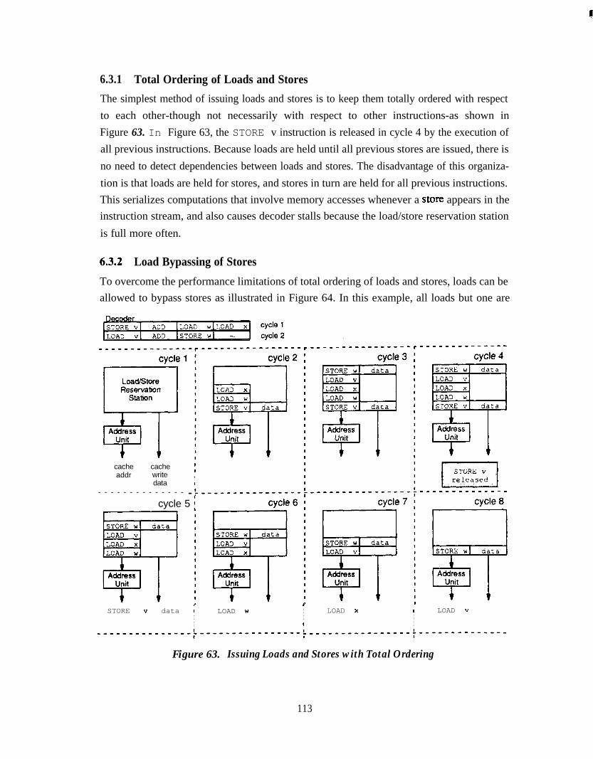
6.3.1 Total Ordering of Loads and StoresThe simplest method of issuing loads and stores is to keep them totally ordered with respectto each other-though not necessarily with respect to other instructions-as shown inFigure 63. In Figure 63, the STORE v instruction is released in cycle 4 by the execution ofall previous instructions. Because loads are held until all previous stores are issued, there isno need to detect dependencies between loads and stores. The disadvantage of this organiza-tion is that loads are held for stores, and stores in turn are held for all previous instructions.This serializes computations that involve memory accesses whenever a store appears in theinstruction stream, and also causes decoder stalls because the load/store reservation stationis full more often.
613.2 Load Bypassing of Stores
To overcome the performance limitations of total ordering of loads and stores, loads can beallowed to bypass stores as illustrated in Figure 64. In this example, all loads but one are
cacheaddr
cache ;write ,data I
- - - - - - - - - - - - - -
cycle 5 i
STORE v data ;I
LOAD w I LOAD x I LOAD vI I II I I
---------------t----------------, '----------------~--------------
Figure 63. Issuing Loads and Stores with Total Ordering
113

erSTORE vi ADD ILOAD wlLOAD cycle 1LOA VI ADD ISTORE WI - cycle 2
----m---mm------mm-m -, _ _ _ - _ _ - _ _ - _ - - - - _ - - - - - - ,- - - -m----m_________m-
cvcle 1 :
StoreReservation
Station'xJgJ@Cl
Idre
8II AdI cII
I I StoreBuffer 7-=F
LOAD w
II
11
cacheaddr
Icache Iwrite 1data :
II
cycle 4cycle 41
LJ-y-ylLOAD v
1 1Address
Unit
cvcle 5 I cvcle 6-2
STORE WI dataSTORE WI dataSTORE VI dataSTORE VI data
00 II
1 1Address
Unit
ST3RE WI data
t cI
II,LOAD v.
1 1Address
Unit
STORE w 1 data
t I
I
4II
+ tLOAD "
t tSTORE " data
I
I
Figure 64. Load Bypassing of Stores
issued before the STORE v instruction is released for issue, even though the loads follow theSTORE v in the instruction sequence. To support load bypassing, the hardware organiza-tion shown in Figure 64 includes separate reservation stations and address units for loadsand stores and a store buffer (Section 6.3.5 below describes an organization that eliminatesthe reservation stations, using a central window and a single address unit).
114

I
The store buffer is required because a store instruction can be in one of two different stagesof issue: before address computation and translation have been performed, and after ad-dressing computation and translation but before the store is committed to the data cache.Store addresses must be computed before loads are issued so that dependencies can bechecked, but stores must be held after address computation until previous instructions com-plete. Figure 64 shows that the dependent LOAD v instruction is not issued until theSTORE v instruction is issued, even though preceding loads are allowed to bypass thisstore. If a store address cannot be determined (for example, because the address base regis-ter is not valid), all subsequent loads are held until the address is valid, because there mightbe a memory dependency.
6.3.3 Load Bypassing with Forwarding
When load bypassing is implemented, it is not necessary to hold a dependent load until theprevious store is issued. As illustrated in Figure 65, the load can be satisfied directly fromthe store buffer if the address is valid and the data is available in the store buffer. This opti-mization avoids the additional latency caused by holding the load until the store is issued,and can help in situations where the compiler is forced by potential dependencies to keepoperand values in memory (for example, in a program containing pointer de-references oraddress operators). In such situations, it is possible to have frequent loads of values recentlystored.
6.3.4 Simulation Results
Figure 66 shows the results of simulating the benchmark programs using the various load/store mechanisms described in this section, for both two-instruction and four-instruction de-coders. The interpretation of the chart labels is as folIows:
l total order - total ordering of loads and stores.
l load byp - load bypassing of stores.
. load fwd- load bypassing of stores with forwarding.
Load bypassing yields an appreciable performance improvement: 11% with a two-instruc-tion decoder, and 19% with a four-instruction decoder. Load forwarding yields a muchsmaller improvement over load bypassing: 1% with a two-instruction decoder and 4% with afour-instruction decoder. The obvious conclusion is that load/store mechanism should sup-port load bypassing. Load forwarding is a less-important optimization that may or may notbe justified, depending on implementation costs.
115

cycle 1cycle 2
---------------------,----------- -----------,----------------- - - - -
LoadReser-vationStation3Address
Unit
cvcle 1dr StoreStore
ReservationReservationStationStation
41
StoreStoreBufferBuffer
11 11
44
cacheaddr
cachewritedata
-------------------- I
-I-
cycle 4
cycle 2
STORE VI data
II
I
I
cycle 5
cycle 3cycle 3
LOAD vLOAD X, STORE WI data
4 1Address Address
Unit Unit
4 1
STORE VI data
t +LOAD w
cycle E
5-rAddressUnit
STORE " data
Figure 65. toad Bypassing of Stores with Forwarding
6.3.5 Implementing Loads and Stores with a Central Instruction Window
The simulation results for load bypassing and load forwarding in Section 6.3.4 used thehardware organization shown in Figure 64. This organization is based on reservation sta-tions to provide the most flexibility in the load and store mechanisms, bu this is an incon-venient implementation for two reasons. First, it assumes two separate address units eachconsisting of a 32-bit adder and (possibly) address-translation hardware. Two address units
116

Speedup Two-Instruction Decoder Speedup Four-Instruction Decoder
low h-mean high
O-total order load byp load fwd
bw h-mean high
total order load byp load fwd
Figure 66. Performance for Various LoadlStore Techniques
are largely unnecessary, because the issue rate for loads and stores is constrained by the data-cache interface to one access per cycle. Second, this organization makes it difficult to deter-mine the original order of loads and stores so that dependency checking can be performed.
For example, when a load is issued, it may have to be checked against a store in the storereservation station, in the store address unit, or in the store buffer. Stores in the store reserva-tion station have not had address computation and translation performed. If a load sequen-tially follows a store that is still in the store reservation station, the load must be held at leastuntil the store is placed into the store buffer. However, there is no information in the reserva-tion stations or store buffer, as defined, to allow the hardware to determine the set of storeson which a given load may depend. Without a mechanism to determine the correct set ofstores, deadlock can occur: a store may hold because of a register dependency on a previousload, while the load holds because it is considered (incorrectly) to depend on the store.
An alternative organization to that shown in Figure 64 is shown in Figure 67. This organiza-tion is based on a central window and has a single address unit. Loads and stores are issued tothe address unit from the central window. A store buffer operates as before to hold storesuntil they are committed to the data cache.
When a load or store instruction is decoded, its address-register value (or a tag) and addressoffset are placed into the central window. The data for a store (or a tag) is placed directly into
117

loads and stores
3CentralWin&w store
data
tAddress
Unit
I *
storeBuffer
cacheaddr
cacheWti&data
Figure 67. Reorganizing the LoadlStore Unit with a Central Instruction Window
the store buffer. From the central window, loads and stores are issued in original programorder to the address unit (this can be accomplished using sequencing tags, as suggested inSection 6.2.3). A load or store cannot be issued from the window until its address-registervalue is valid, as usual. At the output of the address unit, a store address is placed into thestore buffer, and a load address is sent directly to the data cache (the load bypasses stores inthe store buffer). Loads are checked for dependencies against stores in the store buffer. If adependency exists, load data can be forwarded from the store buffer.
Figure 68 repeats the simulation results of Section 6.3.4 for this organization (the results fortotally-ordered loads and stores are shown for continuity, but there is no difference in thiscase). For these results, an eight-entry central window and an eight-entry store buffer wereused. In most cases, there is only a slight performance penalty caused by issuing loads to theaddress unit in order with stores-l % with a two-instruction decoder and 3% with a four-in-struction decoder. For the results in Section 6.3.4, a load could be issued to the data cachewhile a store was simultaneously placed into the store buffer. Since this latter techniquerequires two address units, and since the central-window approach does not reduce perform-ance very much, the implementation using the central window and a single address is a goodcost/performance tradeoff.
118

Speedup3
Two-Instruction Decoder
low h-mean high
0total order load byp load fwd
Figure 68. Peflormance for Variow LoadlStore Techniquesusing a Central Window
6.3.6 Effects of Store Buffer Size
Speedup Four-Instruction Decoder
low h-mean high. . . .., :...:.
total order load byp load fwd
Figure 69 shows the effects of store-buffer size on performance, for a processor having aneight-entry central window and implementing load bypassing with forwarding. With a two-instruction decoder, both a four-entry and a two-entry store buffer have nearly identical per-formance to an eight-entry buffer. With a four-instruction decoder, a four-entry buffercauses a 1% performance loss over an eight-entry buffer, and a two-entry buffer causes a 4%loss. The four-entry buffer is a good choice for the four-instruction decoder, because it hasgood performance and the small number of entries facilitate dependency checking.
6.3.7 Memory Dependency Checking
The organization of Figure 67 greatly simplifies memory dependency checking, in compari-son to the organization in Figure 64, because loads and stores are issued to the address unit inorder. When a load is issued, its address is checked for dependencies against all valid ad-dresses in the store buffer. The store buffer contains only stores that sequentially precededthe load, and the store buffer is the only location for these stores until they are issued, afterwhich dependency checking no longer matters.
If a load address matches an address in the store buffer and load forwarding is implemented,the load data are supplied, if available, directly from the store buffer. The dependency logic
119

Speedup Two-Instruction Decoder Speedup
Number of Entries Number of Entries
Four-Instruction Decoder
low h-mean hiah
8 4 2
Figure 69. Efect of Store-Bugler Sizes
must identify the most recent matching store-buffer entry, because the address of more thanone store-buffer entry may match the load address. The most recent entry contains the re-quired data (or a tag for these data). If forwarding is not implemented, the load is held if itsaddress matches the address of any store-buffer entry, without regard to the number ofmatching entries, until all matching store-buffer entries are committed to the data cache.
To reduce the logic chains involved in dependency checking and forwarding, these opera-tions can be performed as a load is issued to the data cache, with the load being squashed orcanceled as required if a dependency is detected. Squashing and canceling may require sup-port in the data cache, and these operations are possible only if loads are free of side-effectsin the system.
If load forwarding is not implemented, the comparators used to detect memory dependen-cies can be reduced by checking a subset of the full address. Figure 70 shows how perform-ance is reduced as dependency checking is limited to 8,4,2, and 1 address bits. Althoughlimiting address checking in this manner sometimes causes false dependencies (for theseresults, low-order address bits were compared under the assumption that these bits have themost variation and are least likely to compare falsely), the effect on performance is verysmall until less than 8 bits are used. These results indicate that 8-bit comparators cause
120
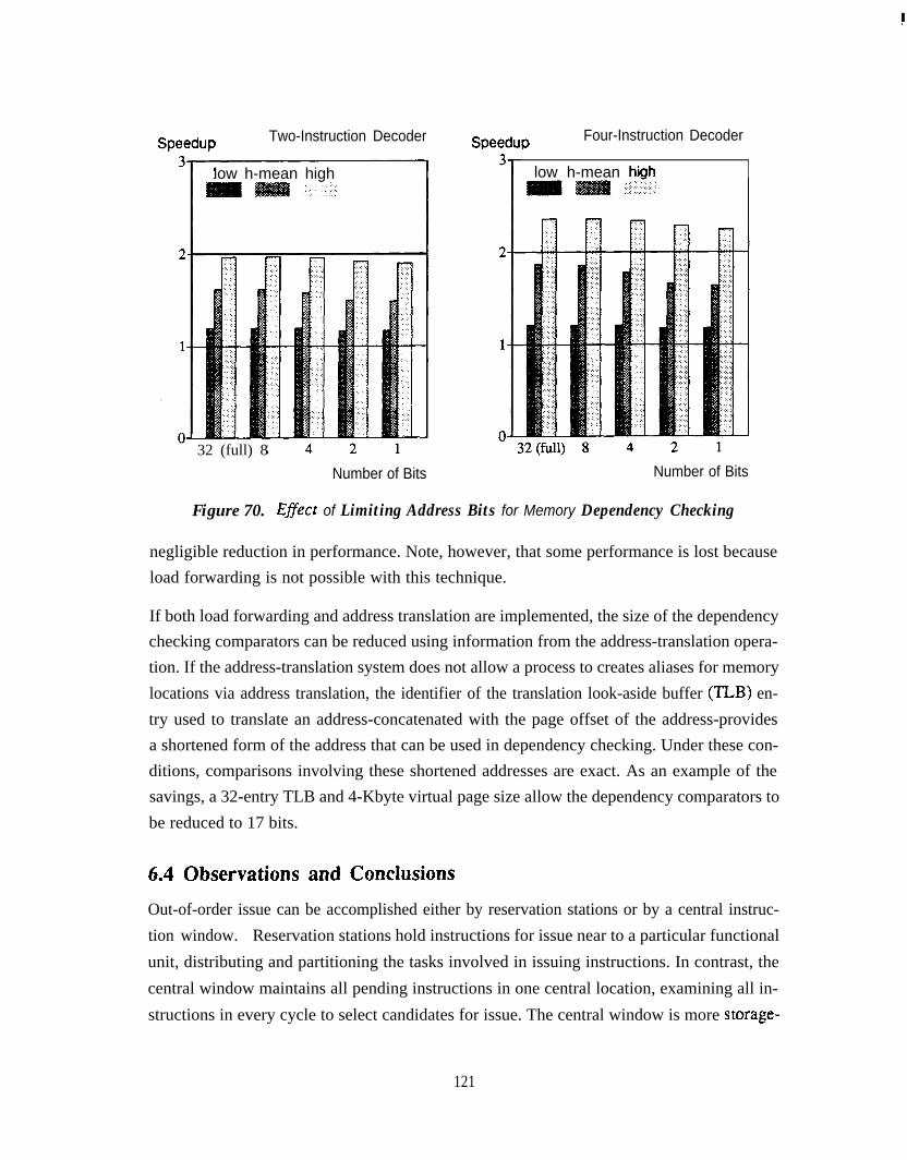
Speedup Two-Instruction Decoder Speedup Four-Instruction Decoder
low h-mean high
I-32 (full) 8
Number of Bits
low h-mean hiah
Number of Bits
Figure 70. EfSect of Limiting Address Bits for Memory Dependency Checking
negligible reduction in performance. Note, however, that some performance is lost becauseload forwarding is not possible with this technique.
If both load forwarding and address translation are implemented, the size of the dependencychecking comparators can be reduced using information from the address-translation opera-tion. If the address-translation system does not allow a process to creates aliases for memorylocations via address translation, the identifier of the translation look-aside buffer (TLB) en-try used to translate an address-concatenated with the page offset of the address-providesa shortened form of the address that can be used in dependency checking. Under these con-ditions, comparisons involving these shortened addresses are exact. As an example of thesavings, a 32-entry TLB and 4-Kbyte virtual page size allow the dependency comparators tobe reduced to 17 bits.
6.4 Observations and ConclusionsOut-of-order issue can be accomplished either by reservation stations or by a central instruc-tion window. Reservation stations hold instructions for issue near to a particular functionalunit, distributing and partitioning the tasks involved in issuing instructions. In contrast, thecentral window maintains all pending instructions in one central location, examining all in-structions in every cycle to select candidates for issue. The central window is more storage-
121

efficient, and consolidates all of the scheduling logic into a single unit. However, the sched-uling logic is more complex than the scheduling logic of any given reservation station, pri-marily because there are more instructions in the central window than in any single reserva-tion station and because functional-unit conflicts must be resolved by the central window.Still, overall considerations weigh in favor of the central window. An alternative to twopub-
lished central-window proposals-the dispatch stack and register update unit-relies on thereorder buffer to maintain instruction-sequencing information. This is one of several exam-ples of synergy between hardware components in the super-scalar processor.
Loads and stores present several impediments to high instruction throughput, because of is-sue constraints, addressing operations, and hardware interfaces associated with memory ac-cesses. Requirements of correctness and restartability reduce the opportunities to gainconcurrency by scheduling loads and stores out-of-order. Furthermore, the hardware re-quired to achieve additional concurrency is expensive in relation to the performance benefitsprovided by this hardware. Compiler scheduling of loads and stores is not as effective as forother instructions (for the general-purpose benchmarks used in this study), because the com-piler has little knowledge of memory dependencies that can arise during execution.
Of all the alternatives examined in this chapter, an organization implementing load bypass-ing (without forwarding) with a central window and a store buffer provides the best tradeoffof hardware complexity and performance. This organization requires a single address unitthat is used by loads and stores in their original program order. Memory dependency check-ing can be performed with eight low-order bits of the memory address with no appreciableloss in performance, and dependency checking is not concerned with the order of stores inthe store buffer as it is when load forwarding is implemented. The store buffer requires onlyfour entries. The performance with this organization is not the best that can be achieved, butis still good, because it allows loads to be issued out-of-order with respect to stores.
122
Chapter 7Conclusion
This research has used an experimental approach to architecture design: processor featuresare evaluated in light of the performance they provide. Trace-driven simulation has permit-ted the evaluation of a large number of super-scalar design alternatives for a large sample ofgeneral-purpose benchmark applications. This approach has identified major hardware
components that are required for best performance and has uncovered techniques that sim-plify hardware with little reduction in performance. By defining the limits of super-scalarhardware, by illustrating the complexity of super-scalar hardware, and by suggesting possi-ble software support, this research has established a basis for future research into hardwareand software tradeoffs for super-scalar processor design.
This thesis shows that a general-purpose, super-scalar processor needs four major hardwarefeatures for best performance: out-of-order execution, register renaming, branch prediction,and a four-instruction decoder. The complexity of these features-although not unmanage-able-may argue against the goal of achieving highest possible performance. However,hardware complexity must be considered in view of hardware simplifications which havebeen proposed throughout this study. This chapter summarizes these simplifications andemphasizes that-even if hardware is simplified in many ways-performance is not re-duced as much as when one of the four major features list above is removed.
This study has also pointed out several avenues for further research, primarily in the direc-tion of software support. The general-purpose benchmark applications used in this study donot lend themselves to software scheduling as readily as many scientific applications, butthere are still many ways in which software can help simplify hardware and improve per-formance.
7.1 Major Hardware FeaturesTable 6 summarizes the performance advantages of out-of-order execution, register renam-ing, branch prediction, and a four-instruction decoder. Each entry in Table 6 is the relativeperformance increase due to adding the given feature, in a processor that has all other listedfeatures. This simple summary indicates that each of these features is important in its ownright. However, these features are interdependent in ways not illustrated by Table 6.
Branch prediction and a four-instruction decoder overcome the two major impediments tosupplying an adequate instruction bandwidth for out-of-order execution: fetch stalls due to
123

Table 6. Performance Advantage of Major Processor Features
Out-of-order Register Branch Four-instructionexecution renaming prediction decoder
52% 36% 30% 1874
branch resolution and decoder inefficiency caused by instruction misalignment. Tech-niques to overcome the branch delay in scalar processors, such as compiler scheduling ofbranch delays, are not effective in a super-scalar processor for general-purpose applicationsbecause of the frequency of branches and the magnitude of the branch-delay penalty. With aspeedup of two, the branch delay represents about eight instructions. With branch predic-tion, a four-instruction decoder achieves higher performance than a two-instruction de-coder, because the four-instruction decoder supplies adequate instruction bandwidth even inthe face of misaligned instruction runs.
Out-of-order execution and register renaming not only provide performance in the expectedways, but also provide performance by supporting branch prediction. The instruction win-dow for out-of-order execution provides a buffer in which the instruction fetcher can storeinstructions following a predicted branch, and register renaming provides a mechanism forrecovering from mispredic ted branches.
Table 6 implies another way in which out-of-order execution, register renaming, branchprediction, and a four-instruction decoder depend on each other. These features togetherprovide more performance than is provided by each feature taken separately, because eachrelative improvement in Table 6 assumes that the other features are already implemented.Thus, it is difficult to justify implementing anything but the complete set of features, exceptthat this observation presupposes that cycle time is not affected and that the performancegoal justifies the design complexity.
The complexity of the super-scalar processor is its most troubling aspect. None of the majorfeatures by itself is particularly difficult to implement, but interdependencies between thesefeatures can create complex hardware and long logic delays. Complexity is significantlyincreased by the goal of decoding, issuing, and executing more than one instruction per cy-cle. Often, this complexity manifests itself in the arbitration logic that allocates multiple,shared processor resources among multiple contenders. The super-scalar processor has anumber of different arbiters, each with its own complexity and timing constraints. The
124

design of these arbiters has been widely ignored in the published literature and in this studybecause arbiter design is very dependent on the hardware technology and implementation.
7.2 Hardware Simplifications
Though a super-scalar processor is complex, this study has suggested that many hardwaresimplifications are possible. This section summarizes these simplifications and their effectson performance. Although it is possible that, when a super-scalar processor is simplified in anumber of ways, the cumulative effect of these simplifications reduces performance morethan removing one of the major processor features listed in Section 7.1, this section showsthat this is not the case.
Table 7 lists several progressively-simplified processor designs, showing the cumulativeperformance degradation. The cumulative degradation of each design is the percentage re-duction in performance (based on the harmonic mean) relative to the processor configura-tion described in Section 3.3. Figure 7 1 and Figure 72 present the speedups of the configu-
rations in Table 7. Although one conclusion presented in Section 7.1 was that a four-instruc-tion decoder provides better performance than a two-instruction decoder, data for the two-
Table 7. Cumulative Eflects of Hardware Simplifications
Hardware Simplification (cumulative)
a Iexecution model described in Section 3.3,with branch prediction in instruction cache
blLiiW3.4) ~single-port array in instruction cache for branch-prediction 1 -3% 1 -4% 1
7C limiting decoder to four register-file read ports (Section 4.4) anddecoding a single branch instruction per cycle (Section 4.5.3) 1 -3% 1 -6% 1
d waiting until mispredicted branch reaches the head of the reorderbuffer before restarting (Section 5.2.1) -7% -11%
e central instruction window (not compressed--Section 6.2.3), limitedoperand buses (Section 6.2.4), single address unit (Section 6.3.5)
-80/0 -15%
f no load forwarding from store buffer (Sections 6.3.2 and 6.3.3),a-bit dependency checking (Section 6.3.7) -9% -17%
\
9 I no load bypassing of stores (Section 6.3.1)
‘speedup = 1.64 2speedup = 1.94
125
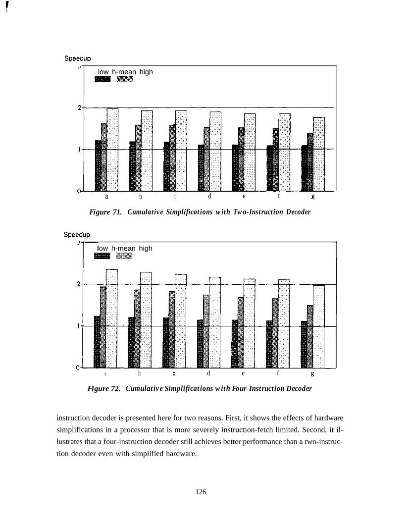
Speedup-I
low h-mean high
”
a b C d e f g
Figure 71. Cumulative Simplifications with Two-Instruction Decoder
Speedup
low h-mean high,=:.:.;:.:p*@$g+..::::ti!..PSSX
a b d e f g
Figure 72. Cumulative Simplifications with Four-Instruction Decoder
instruction decoder is presented here for two reasons. First, it shows the effects of hardwaresimplifications in a processor that is more severely instruction-fetch limited. Second, it il-lustrates that a four-instruction decoder still achieves better performance than a two-instruc-tion decoder even with simplified hardware.
126

Many of the hardware simplifications do not reduce performance very much because theinstruction window decouples instruction-fetch and instruction-execution limitations. Theaverage rates of fetching and execution are more important to overall performance thanshort-term limitations. Other simplifications are the direct result of the hardware featuresdescribed in Section 7.1. For example, the instruction-ordering information retained by thereorder buffer allows this information to be discarded as instructions are allocated entries inthe instructions window, avoiding the need to compress the window and simplifying its im-plementation. As a further example, the dynamic scheduling of the instruction window al-lows good performance with a limited number of operand buses between the window and thefunctional units.
Eliminating load bypassing is the only simplification listed in Table 7 that causes lower per-formance than the removal of out-of-order execution, register renaming, branch prediction,or a four-instruction decoder. Apparently, the conclusion of Section 6.3-that load bypass-ing is the most important feature of the load/store mechanism-is still valid in a simplifiedprocessor.
7.3 Future Directions
This study has suggested several areas where software support can improve processor per-formance or simplify the hardware. The suggested support raises several important ques-tions.
The instruction format proposed in Section 4.4.2 relies on software to schedule the use ofregister-file read ports. Software can either use common source registers among several in-structions or use dependent instructions to reduce the demands on register-file read ports.Whether either approach is feasible is an open question. Furthermore, using dependent in-structions to reduce register-file demands conflicts with the overall software-schedulinggoal of helping the processor to fetch and decode independent instructions. It is difficult to
determine without much further study the degree to which these goals conflict.
Another proposal in this study is that software can improve the efficiency of the instructionfetcher by loop unrolling, aligning instruction runs, and scheduling instructions after abranch to pad the decoder. Hardware-based aligning and merging indicates that these can beimportant optimizations, but further research is required to determine whether software canperform aligning and merging with an overall benefit, particularly with respect to the effectof the increased code density on the hit ratio of the instruction cache.
127

1
Finally, though this study has established a starting point for future research, many of theconclusions have been reached with the assumption of no software support. Further studymay show that more hardware should be provided to exploit the instruction independencethat software is able to provide, or that less hardware is required because software is able toprovide benefits that were not anticipated in this study.
128
J

References
[Acosta et al. 19861R.D. Acosta, J. Kjelstrup, and H.C. Tomg, “An Instruction Issuing Approach to En-hancing Performance in Multiple Functional Unit Processors.” IEEE Transactionson Computers, Vol. C-35, (September 1986), pp. 815-828.
[Agerwala and Cocke 19871T. Agerwala and J. Cocke, “High Performance Reduced Instruction Set Processors.”Technical Report RC12434 (#55845), IBM Thomas J. Watson Research Center,Yorktown, NY, (January 1987).
[Backus 19781J. Backus, “Can Programming Be Liberated From the Von Neumann Style? A Func-tional Style and Its Algebra of Programs.” Communications of the ACM, Vol. 2 1,No. 8, (August 1978), pp. 613641.
[Chaitin et al. 19811G.J. Chaitin, M.A. Auslander, A.K. Chandra, J. Cocke, M.E. Hopkins, and P.W.Markstein, “Register Allocation via Coloring.” Computer funguages, Vol. 6, No. 1(198 l), pp.47-57.
[Charlesworth 19811A.E. Charlesworth, “An Approach to Scientific Array Processing: The ArchitecturalDesign of the AP-12OB/FPS 164 Family.” Computer, Vol. 14, (September 1981),pp. 18-27.
[Colwell et al. 19871R.P. Colwell, R.P. Nix, J.J. O’Donnel, D.B. Papworth, and P.K. Rodman, “A VLIWArchitecture for a Trace Scheduling Compiler,” Proceedings ofthe Second Interna-tional Conference on Architectural Supportfor Programming Languages and Oper-ating Systems, (October 1987), pp. 180-192.
[Ditzel and McLellan 19871
D.R. Ditzel and H.R. McLellan, “Branch Folding in the CRISP Microprocessor: Re-ducing Branch Delay to Zero.” Proceedings of the 14 th Annual Symposium on Com-puter Architecture, (June 1987), pp. 2-9.
129

[Dwyer and Torng 19871H.C. Tomg, “A Fast Instruction Dispatch Unit for Multiple and Out-of-SequenceIssuances.” School of Electrical Engineering Technical Report EE-CEG-87-15,(November 1987), Cornell University, Ithaca, NY.
[Fisher 19811J.A. Fisher, “Trace Scheduling: A Technique for Global Microcode Compaction.”IEEE Transactions on Computers, Vol. C-30, (July 1981), pp. 478-490.
[Fisher 19831J.A. Fisher, “Very Long Instruction Word Architectures and the ELI-512.” Pro-ceedings of the 10th Annual Symposium on Computer Architecures, (June 1983),pp. 140-150.
[Foster and Riseman 19721C.C. Foster and E.M. Riseman, “Percolation of Code to Enhance Parallel Dispatch-ing and Execution.” IEEE Transactions on Computers, Vol. C-21, (December1972), pp. 1411-1415.
[Gross and Hennessy 19821T.R. Gross and J.L. Hennessy, “Optimizing Delayed Branches.” Proceedings ofIEEE Micro-IT, (October 1982), pp. 114-120.
[Hennessy and Gross 19831J. Hennessy and T. Gross, “Postpass Code Optimization of Pipeline Constraints.”ACM Transactions on Programming Languages and Systems, Vol. 5, No. 3, (July1983), 422-448.
[Hennessy 19861J.L. Hennessy, “RISC-Based Processors: Concepts and Prospects.” New Frontiersin Computer Architecture Conference Proceedings, (March 1986), pp. 95-103.
[Hwu and Chang 19881W.W. Hwu and P.P. Chang, “Exploiting Parallel Microprocessor Microarchitec-tures with a Compiler Code Generator.” Proceedings of the 15th Annual Symposiumon Computer Architecture, (June 1988), pp. 45-53.
130

[Hwu and Patt 19861W. Hwu and Y.N. Patt, “HPSm, a High Performance RestrictedDataFlow Architec-ture Having Minimal Functionality.” Proceedings of the 13 th Annumal Symposiumon Computer Architecture, (June 1986), pp. 297-307.
[Hwu and Patt 19871W.W. Hwu and Y.N. Patt, “Checkpoint Repair for Out-of-Order Execution Ma-chines.” Proceedings of the 14th Annual Symposium on Computer Architecture,(June 1987), pp. 18-26.
[Jouppi and Wall 19881N.P. Jouppi and D.W. Wall, “Available Instruction-Level Parallelsim for Super-scalar and Superpipelined Machine.” Technical Note TN-2, Digital Equipment Cor-poration Western Research Laboratory , Palo Alto, CA, (September 1988). Alsopublished in Proceedings of the Third international Conference on ArchitecturalSupport for Programming Languages and Operating Systems, (April 1989), pp.272-282.
[Keller 19751R.M. Keller, “Look-Ahead Processors.” Computing Surveys, Vol. 7, No. 4, (De-cember 1975), pp. 177-195.
[Lam 19881M. Lam, “Software Pipelining: An Effective Scheduling Technique for VLIW Ma-chines.” Proceedings of the SIGPLAN ‘88 Conference on Programming LanguageDesign and Implementation, (June 1988), pp. 3 18-328.
[Lee and Smith 19841J.K.F. Lee and A.J. Smith, “Branch Prediction Strategies and Branch Target BufferDesign.” IEEE Computer, Vol. 17, (January 1984), pp. 6-22.
[McFarling and Hennessy 19861S. McFarling and J. Hennessy, “Reducing the Cost of Branches.” Proceedings of the13th Annual Symposium on Computer Architecture, (June 1986), pp. 396-404.
[MIPS 861MIPS Computer Systems, Inc., MIPS Language Programmer’s Guide, (1986).
131

[Mueller et al. 19841R.A. Mueller, M.R. Duda, and S.M. O’Haire, “A Survey of Resource AllocationMethods in Optimizing Microcode Compilers.” Proceedings of the 17th AnnualWorkshop on Microprogramming, (October 1984), pp. 285-295.
[Nicolau and Fisher 19841A. Nicolau and J.A. Fisher, “Measuring the Parallelism Available for Very Long In-struction Word Architectures.” IEEE Transactions on Computers, Vol. C-33, (No-vember 1984), pp. 968-976.
[Patt et al. 1985a]Y.N. Patt, W. Hwu, and M. Shebanow, “HPS, A New Microarchitecture: Rationale
and Introduction.” Proceedings of the 18th Annual Workshop on Microprogram-ming, (December 1985), pp. 103-108.
[Patt et al. 1985b]Y.N. Patt, S.W. Melvin, W. Hwu, and M.C. Shebanow, “Critical Issues RegardingHPS, A High Performance Microarchitecture.” Proceedings of the 18th AnnualWorkshop on Microprogramming, (December 1985), pp. 109-l 16.
[Pleszkun et al. 19871A. Pleszkun, J. Goodman, W.C. Hsu, R. Joersz, G. Bier, P. Woest, and P. Schecter,“WISQ: A Restartable Architecture Using Queues.” Proceedings of the 14th An-nual Symposium on Computer Architecture, (June 1987), pp. 290-299.
[Pleszkun and Sohi 19881A.R. Pleszkun and G.S. Sohi, “The Performance Potential of Multiple FunctionandUnit Processors.” Proceedings of the 15th Annual Symposium on Computer Archi-tecture, (June 1988), pp. 3744.
[Przybylski et al. 19881S. Przybylski, M. Horowitz, and J. Hennessy, “Performance Tradeoffs in Cache De-sign.” Proceedings of the 15th Annual Symposium on Computer Architecture, (June1988), pp. 290-298.
132

. [Rau and Glaeser 19811B.R. Rau and C.D. Glaeser, “Some Scheduling Techniques and an Easily Schedul-able Horizontal Architecture for High Performance Scientific Computing.” Pro-ceedings of the 14th Annual Workshop on Microprogramming, (October 1981), pp.183-198.
[Riseman and Foster 19721E.M. Riseman and C.C. Foster, “The Inhibition of Potential Parallelism by Condi-tional Jumps.” IEEE Transactions on Computers, Vol. C-21, (December 1972), pp.1405-1411.
[Sohi and Vajapeyam 19871G.S. Sohi and S. Vajapeyam, “Instruction Issue Logic for High-Performance Inter-ruptable Pipelined Processors.” Proceedings of the 14th Annual Symposium onComputer Architecture, (June 1987), pp. 27-34.
[Smith et al. 19881M.D. Smith, M. Johnson, and M.A. Horowitz, “Limits on Multiple Instruction Is-sue.” Proceedings of the Third International Conference on Architectural Supportfor Programming Languages and Operating Systems, (April 1989), pp. 290-302.
[Smith and Pleszkun 19851J.E. Smith and A.R. Pleszkun, “Implementation of Precise Interrupts in PipelinedProcessors.” Proceedings of the 12th Annual International Symposium on Com-puter Architecture, (June 1985), pp. 36-44.
[Thorton 19701J.E. Thorton, Design of a Computer-The Control Data 6600. Scott, Foresman andCo., Glenview IL, (1970).
[Tjaden and Flynn 19701G.S. Tjaden and M.J. Flynn, “Detection and Parallel Execution of Independent In-structions.” IEEE Transactions on Computers, Vol. C-19, No. 10, (October 1970),pp. 889-895.
133

[Tjaden 19721G.S. Tjaden and M.J. Flynn, “Representation and Detection of Concurrency usingOrdering Matrices.” Ph.D. Dissertation, The Johns Hopkins University, Baltimore,MD, (1972).
[Tjaden and Flynn 19731G.S. Tjaden and M.J. Flynn, “Representation of Concurrency with Ordering Matri-ces.” IEEE Transactions on Computers, Vol. C-22, No. 8, (August 1973), pp.752-761.
[Tomasulo 19671R.M. Tomasulo, “An Efficient Algorithm for Exploiting Multiple ArithmeticUnits.” IBM Journal, Vol. 11, (January 1967), pp. 25-33.
[Torng 19841H.C. Tomg, “An Instruction Issuing Mechanism for Performance Enhancement.”School of Electrical Engineering Technical Report EE-CEG-84-1, (February1984), Cornell University, Ithaca, NY.
[Uht 19861A.K. Uht, “An Efficient Hardware Algorithm to Extract Concurrency From Gen-eral-purpose Code.” Proceedings of the Nineteenth Annual Hawaii InternationConference on System Sciences, (1986), pp. 41-50.
[ Wedig 19821R.G. Wedig, “Detection of Concurrency in Directly Executed Language InstructionStreams.” Ph.D. Dissertation, Stanford University, Stanford, CA (June 1982).
[Weiss and Smith 19841S. Weiss and J.E. Smith, “Instruction Issue Logic in Pipelined Supercomputers.”IEEE Transactions on Computers, Vol. C-33 (November 1984), pp. 1013-1022.
[Weiss and Smith 19871S. Weiss and J.E. Smith, “A Study of Scalar Compilation Techniques for PipelinedSupercomputers.” Proceedings of the Second International Conference on Archi-tectural Support for Programming Languages and Operating Systems, (October1987), pp. 105-109.
[Wulf 19881W.A. Wulf, “The WM Computer Architecture.” Architecture News, (January1988), pp. 70-84.
134
. .
Related Documents


