Super II Supervisor and Technical Manual Setra Systems, Inc Weighing Systems Division 159 Swanson Road Boxborough, MA 01719 TM TDSS2068-01 Rev D 12/01

Welcome message from author
This document is posted to help you gain knowledge. Please leave a comment to let me know what you think about it! Share it to your friends and learn new things together.
Transcript
Super IISupervisor and Technical
Manual
Setra Systems, IncWeighing Systems Division
159 Swanson RoadBoxborough, MA 01719
TM
TDSS2068-01 Rev D 12/01
Table of ContentsIntroduction ............................................................................................................................................... 4
Supervisor Setup .......................................................................................................................................... 9
Soft Key: PRINT SETUP ............................................................................................ 10
Soft Key: SAMPLE SETUP ....................................................................................... 18
Soft Key: ACCURCY SETUP .................................................................................... 20
Soft Key: PORTS SETUP........................................................................................... 22
Soft Key: TIME/DATE ................................................................................................ 24
Soft Key: UNITS ENABLED ..................................................................................... 27
Soft Key:DATBASE SETUP ...................................................................................... 30
Soft Key:TRANSAC SETUP ..................................................................................... 34
Soft Key:ID NAME SETUP ....................................................................................... 38
Soft Key: MACRO SETUP ........................................................................................ 41
Soft Key: SETUP SECURTY ..................................................................................... 47
Soft Key: BEEPER CONTROL .................................................................................. 49
Bases Setup ...................................................................................................................................................51
Soft Key: CALIB .......................................................................................................... 52
Soft Key: SPEED ......................................................................................................... 56
Soft Key: ZERO ........................................................................................................... 58
Soft Key: RESOLUT ................................................................................................... 60
Soft Key: INFO ............................................................................................................ 62
Soft Key: NAME ......................................................................................................... 64
Soft Key: ADDRESS................................................................................................... 66
Soft Key: BASERST .................................................................................................... 69
Technical Setup ...........................................................................................................................................70
Soft Key:GREETNG ................................................................................................... 72
Soft Key: BACKLIT ..................................................................................................... 74
Soft Key: SETUP TRANSFR ..................................................................................... 77
Soft Key: RESET.......................................................................................................... 80
Soft Key: AUTO SWITCH ......................................................................................... 84
Soft Key: ALARMS..................................................................................................... 86
Soft Key: DIG INP ...................................................................................................... 90
Soft Key: SETUP SECURTY ..................................................................................... 92
Soft Key: HYSTERS .................................................................................................... 94
Soft Key: APW QTY ................................................................................................... 96
Appendix A: RS232 Serial Port Communications ............................................................................99
Appendix B: ScriptcoderTM Custom Label Printing..........................................................................106
Appendix C: Battery Option ....................................................................................................................114
Appendix D: Strain Gauge Remote Scale Option ............................................................................116
Appendix E: Specifications ......................................................................................................................122
Appendix F: Glossary .................................................................................................................................125
Appendix G: Warranty ...............................................................................................................................127
Appendix H: Warnings ...............................................................................................................................128
FCC Warning .................................................................................................................................................129
EC Declaration of Conformity .................................................................................................................130
Index ................................................................................................................................................................131

Introduction • Super II 4
Introduction
Introduction • Super II 5
Introduction
For many counting or weighing applications, the Super II default settings are adequate and the scale canbe used just as it comes from the factory. However, often the scale performance can be enhanced oroperation simplified if the factory settings are changed, or if some of the more specialized features areenabled. This manual is designed to instruct the programmer in the procedures used to change factorydefault settings for numerous scale features and, also, to describe how to use certain other features thatare not enabled at the factory. Access to these settings can be password protected to assure that thesettings, once programmed, are only changed by authorized personnel.
The manual is divided into four sections: Supervisor Setup, Technical Setup, Bases Setup and the appendi-ces. Supervisor Setup, in general, allows application specific customization of the scale, such as program-ming the minimum sample size that will be allowed for counting certain parts, setting the baud rate forcommunicating with a particular printer, changing the name of field identifiers that will appear on printedlabels and customizing prompts that will walk the user through a recurring counting or weighing transac-tion. Technical Setup allows customization of the scale that tends to be more related to scale performance,as well as several other scale specific parameters. The Bases Setup section describes how to configure thenetwork of bases, including performance parameters. The fourth section consists of appendices thatexplain, at length, how to use two standard features, RS232 data communications and the ScriptCoderlabel making routine. It also describes the use of the optional battery and strain gauge remote scale optionwhich can be purchased separately.
This setups manual will enable customization and/or implementation of the following scale features:
PrintingText and bar coded labels can be printed directly from the Super II controller using the optional Dymo®SETRA 300 printer or the more advanced Eltron thermal printer (not available from Setra). ScriptCoderallows easy interfacing to a wide variety of other printers and use of its powerful scripting language canproduce fairly complex labels, if needed.
Multiple Scale SystemsAs described in the Bases Setup section of this manual, a single Super II scale can be converted into asystem consisting of one Super II controller connected to and operating up to eight separate bases. Thesebases can be either Setra variable capacitance load cell bases or more conventional strain gauge load cellbases, or a combination of both. This feature provides the advantage of integrating, at one workstation,high resolution, low capacity bases for the optimal development of average piece weights, with lowresolution, high capacity bases for counting and weighing very large, bulky loads.
Internal DatabaseA flexible internal database can be used to store part numbers and associated data for up to 750 inventoryitems. The ability to instantly recall an item‘s average piece weight from the database can eliminate repeti-tive sampling when that part is frequently counted. The ability to recall descriptive information from thedatabase reduces the need to input data when transaction receipts or other labels are generated.
Transaction LogResident in the scale’s database, this feature chronologically stores the results of each weighing or count-ing operation. The part number, the operator’s name, the time and date of the transaction and the quantitycounted can be automatically stored when the appropriate key is pressed. Transaction reports can beperiodically printed to help track material flow and reconcile inventory miscounts.
Introduction • Super II 6
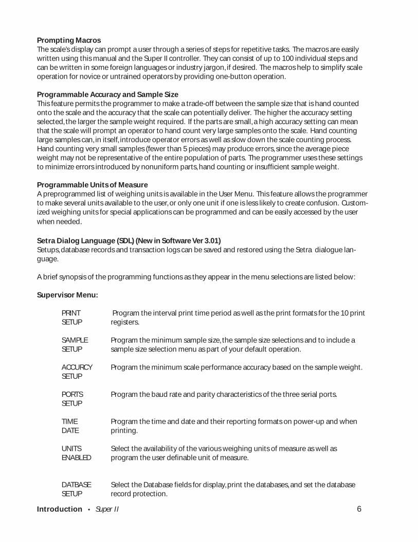
Prompting MacrosThe scale’s display can prompt a user through a series of steps for repetitive tasks. The macros are easilywritten using this manual and the Super II controller. They can consist of up to 100 individual steps andcan be written in some foreign languages or industry jargon, if desired. The macros help to simplify scaleoperation for novice or untrained operators by providing one-button operation.
Programmable Accuracy and Sample SizeThis feature permits the programmer to make a trade-off between the sample size that is hand countedonto the scale and the accuracy that the scale can potentially deliver. The higher the accuracy settingselected, the larger the sample weight required. If the parts are small, a high accuracy setting can meanthat the scale will prompt an operator to hand count very large samples onto the scale. Hand countinglarge samples can, in itself, introduce operator errors as well as slow down the scale counting process.Hand counting very small samples (fewer than 5 pieces) may produce errors, since the average pieceweight may not be representative of the entire population of parts. The programmer uses these settingsto minimize errors introduced by nonuniform parts, hand counting or insufficient sample weight.
Programmable Units of MeasureA preprogrammed list of weighing units is available in the User Menu. This feature allows the programmerto make several units available to the user, or only one unit if one is less likely to create confusion. Custom-ized weighing units for special applications can be programmed and can be easily accessed by the userwhen needed.
Setra Dialog Language (SDL) (New in Software Ver 3.01)Setups, database records and transaction logs can be saved and restored using the Setra dialogue lan-guage.
A brief synopsis of the programming functions as they appear in the menu selections are listed below:
Supervisor Menu:
PRINT Program the interval print time period as well as the print formats for the 10 printSETUP registers.
SAMPLE Program the minimum sample size, the sample size selections and to include aSETUP sample size selection menu as part of your default operation.
ACCURCY Program the minimum scale performance accuracy based on the sample weight.SETUP
PORTS Program the baud rate and parity characteristics of the three serial ports.SETUP
TIME Program the time and date and their reporting formats on power-up and whenDATE printing.
UNITS Select the availability of the various weighing units of measure as well asENABLED program the user definable unit of measure.
DATBASE Select the Database fields for display, print the databases, and set the databaseSETUP record protection.

Introduction • Super II 7
TRANSAC Activate and choose the fields to record in the transaction log, print theSETUP transaction log or transfer to a computer, and clear the transaction log.
ID NAME Change the names of the ID fields.SETUP
MACRO Program up to ten macros (a series of scale operation steps) along withSETUP customizable prompts.
SETUP Program password protection for the Supervisor menusSECURTY
BEEPER Allows the beeper to be disabled.CONTROL
Bases Menu:
CALIB Perform a Span calibration and access the factory linearity calibration and testmenu.
UPDATE Select the filtering and update rate.SPEED
ZERO Set the level of Zero Tracking.TRACK
RESOLUT Set the displayed weight resolution of the scale.
INFO Display information about the bases such as display resolution, zerotracking, sample resolution, and software revision.
NAME Change the name of a base.
ADDRESS Display and change the network address of the bases.
BASERST Force the controller to evaluate the base network.
Technical Menu:
GREETNG Change the greeting message on power-up.
BACKLIT Set up the battery saving modes for the backlight option (if available).
SETUP Send setup and database information through the ports.TRANSFR (Note: Available in Software Version 3.01.)
RESET Return to the factory defaults and clear out separately the Database, PrintRegisters, and Macros.
AUTO Program automatic switching options among multiple bases.SWITCH

Introduction • Super II 8
ALARMS Configure and enable/disable the digital output alarms.
DIG INP Set up the controller for control by outside equipment.
SETUP Program password protection for the Technical and Bases Menu.SECURTY
HYSTERS Set up display hysteresis for more stable display.
APW QTY Program the number of pieces by which the scale counts

Supervisor Setup • Super II 9
Supervisor Setup
Supervisor Setup • Super II 10
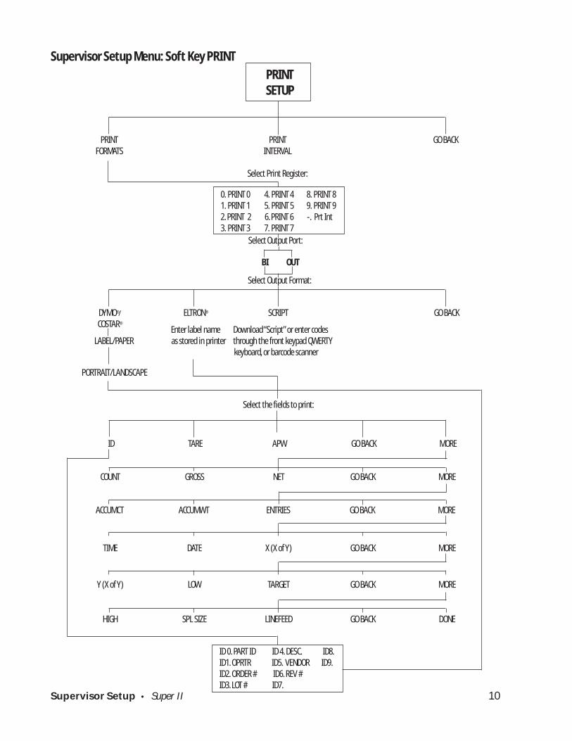
Enter label name Download “Script” or enter codesLABEL/PAPER as stored in printer through the front keypad QWERTY
keyboard, or barcode scanner
PRINT PRINT GO BACKFORMATS INTERVAL
Select Print Register:
Select Output Port:
Select Output Format:
Supervisor Setup Menu: Soft Key PRINT
PRINTSETUP
Select the fields to print:
DYMO®/ ELTRON® SCRIPT GO BACKCOSTAR®
PORTRAIT/LANDSCAPE
HIGH SPL SIZE LINEFEED GO BACK DONE
ID TARE APW GO BACK MORE
COUNT GROSS NET GO BACK MORE
ACCUMCT ACCUMWT ENTRIES GO BACK MORE
TIME DATE X (X of Y) GO BACK MORE
Y (X of Y) LOW TARGET GO BACK MORE
ID 0. PART ID ID 4. DESC. ID8.ID1. OPRTR ID5. VENDOR ID9.ID2. ORDER # ID6. REV #ID3. LOT # ID7.
BI OUT
0. PRINT 0 4. PRINT 4 8. PRINT 81. PRINT 1 5. PRINT 5 9. PRINT 92. PRINT 2 6. PRINT 6 -. Prt Int3. PRINT 3 7. PRINT 7
Supervisor Setup • Super II 11
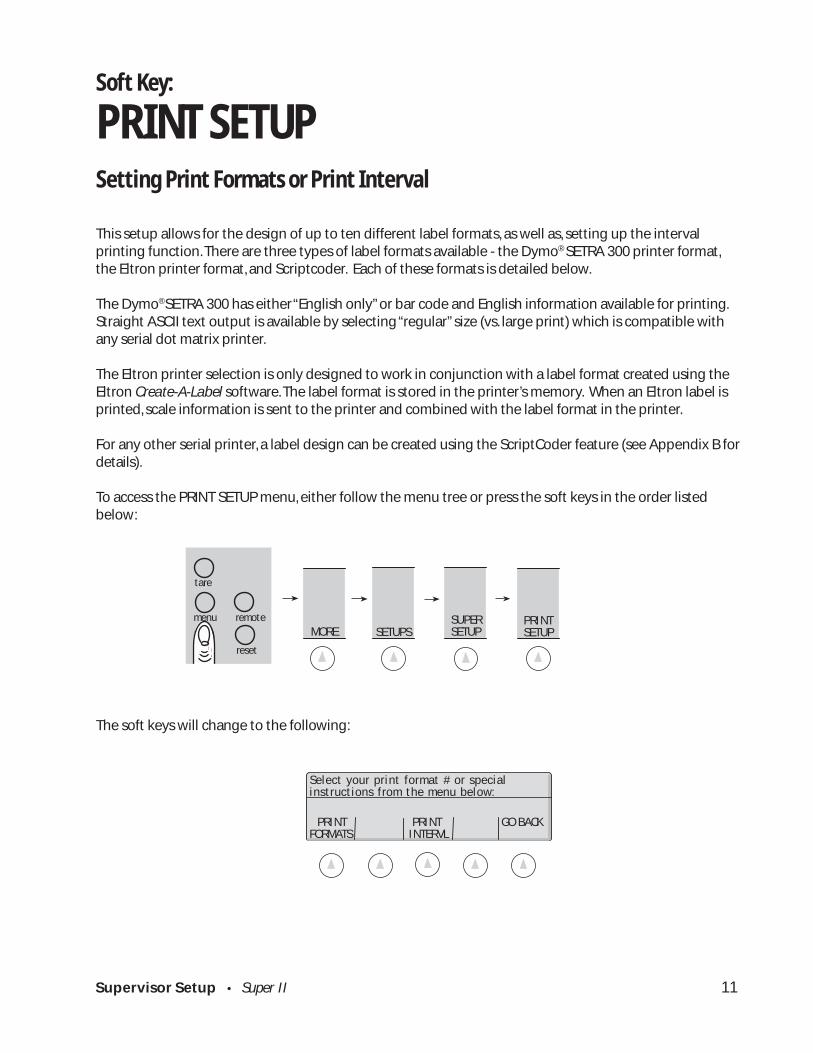
Soft Key:
PRINT SETUPSetting Print Formats or Print Interval
This setup allows for the design of up to ten different label formats, as well as, setting up the intervalprinting function. There are three types of label formats available - the Dymo® SETRA 300 printer format,the Eltron printer format, and Scriptcoder. Each of these formats is detailed below.
The Dymo® SETRA 300 has either “English only” or bar code and English information available for printing.Straight ASCII text output is available by selecting “regular” size (vs. large print) which is compatible withany serial dot matrix printer.
The Eltron printer selection is only designed to work in conjunction with a label format created using theEltron Create-A-Label software. The label format is stored in the printer’s memory. When an Eltron label isprinted, scale information is sent to the printer and combined with the label format in the printer.
For any other serial printer, a label design can be created using the ScriptCoder feature (see Appendix B fordetails).
To access the PRINT SETUP menu, either follow the menu tree or press the soft keys in the order listedbelow:
The soft keys will change to the following:
PRINT PRINT GO BACKFORMATS INTERVL
Select your print format # or specialinstructions from the menu below:
SETUPS MORESUPERSETUP
PRINT SETUP
abc reset
tare
menu remote

Supervisor Setup • Super II 12
Select the function to program:
PRINT FORMATS allows the print registers to be configured..
PRINT INTRVL allows programming a time interval which, when elapsed, causes the scale to printa selected format.
Programming a PRINT Format
Print Format Options: There are ten available formats that can be individually configured. Pressing thePRINT FORMATS soft key described previously will access the Print register selection menu.
Select the NAME soft key to change the print format name (the title that appears in the above screen).Select ON/OFF to enable and disable the print format. Disabled print formats cannot be printed but retaintheir format information. Select # COPYS to program multiple label prints. Pressing # Copys will display thefollowing screen:
Either enter the number of copies to be printed using the numeric keypad and press the ENTER soft key orpress the VARIABL soft key to allow the user to choose the number of copies when printing.
To program a print format, follow the steps below:
1. Using the numeric keypad, select the desired print register to program
2. Select the output port for the print format.
3. Select the print format type:
NAME ON/OFF DELETE # COPYS GO BACK
Select Print Register: 0. Print 0 4. Print 4 8. Print 8 1. Print 1 5. Print 5 9. Print 9 2. Print 2 6. Print 6 –. Prt Int 3. Print 3 7. Print 7
BI OUT GO BACK
Select the port for the printer output.
Enter number of copies to be printed orVARIABL to select number at print time:
ENTER VARIABL GO BACK
COPIES:
Select your printer type:
DYMO ELTRON SCRIPT GO BACK COSTAR
Supervisor Setup • Super II 13
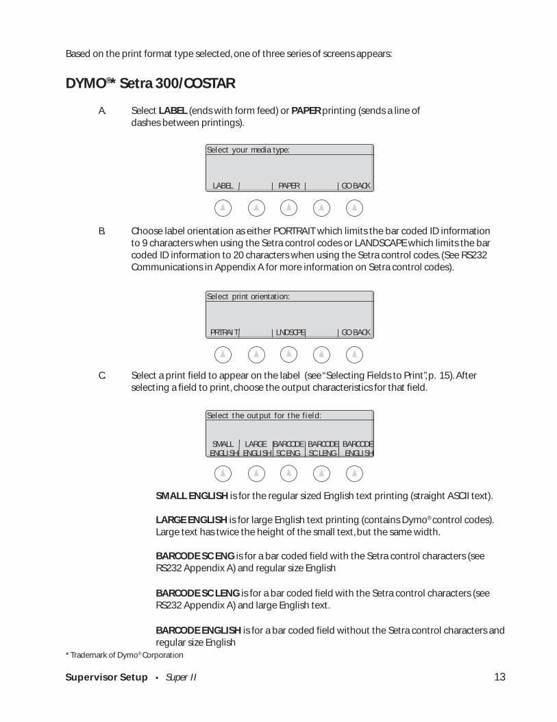
Based on the print format type selected, one of three series of screens appears:
DYMO®* Setra 300/COSTAR
A. Select LABEL (ends with form feed) or PAPER printing (sends a line ofdashes between printings).
B. Choose label orientation as either PORTRAIT which limits the bar coded ID informationto 9 characters when using the Setra control codes or LANDSCAPE which limits the barcoded ID information to 20 characters when using the Setra control codes. (See RS232Communications in Appendix A for more information on Setra control codes).
C. Select a print field to appear on the label (see “Selecting Fields to Print”, p. 15). Afterselecting a field to print, choose the output characteristics for that field.
SMALL ENGLISH is for the regular sized English text printing (straight ASCII text).
LARGE ENGLISH is for large English text printing (contains Dymo® control codes).Large text has twice the height of the small text, but the same width.
BARCODE SC ENG is for a bar coded field with the Setra control characters (seeRS232 Appendix A) and regular size English
BARCODE SC LENG is for a bar coded field with the Setra control characters (seeRS232 Appendix A) and large English text.
BARCODE ENGLISH is for a bar coded field without the Setra control characters andregular size English
* Trademark of Dymo® Corporation
PRTRAIT LNDSCPE GO BACK
Select print orientation:
Select the output for the field:
SMALL LARGE BARCODE BARCODE BARCODE ENGLISH ENGLISH SC ENG SC LENG ENGLISH
LABEL PAPER GO BACK
Select your media type:
Supervisor Setup • Super II 14
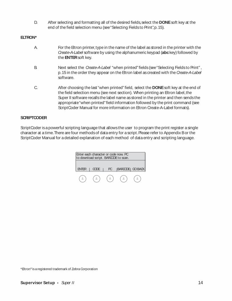
D. After selecting and formatting all of the desired fields, select the DONE soft key at theend of the field selection menu (see “Selecting Fields to Print”, p. 15).
ELTRON*
A. For the Eltron printer, type in the name of the label as stored in the printer with theCreate-A-Label software by using the alphanumeric keypad (abc key) followed bythe ENTER soft key.
B. Next select the Create-A-Label “when printed” fields (see “Selecting Fields to Print” ,p. 15 in the order they appear on the Eltron label as created with the Create-A-Labelsoftware.
C. After choosing the last “when printed” field, select the DONE soft key at the end ofthe field selection menu (see next section). When printing an Eltron label, theSuper II software recalls the label name as stored in the printer and then sends theappropriate “when printed” field information followed by the print command (seeScriptCoder Manual for more information on Eltron Create-A-Label formats).
SCRIPTCODER
ScriptCoder is a powerful scripting language that allows the user to program the print register a singlecharacter at a time. There are four methods of data entry for a script. Please refer to Appendix B or theScriptCoder Manual for a detailed explanation of each method of data entry and scripting language.
*Eltron® is a registered trademark of Zebra Corporation
ENTER CODE PC BARCODE GO BACK
Enter each character or code now. PCto download script. BARCODE to scan.

Supervisor Setup • Super II 15
Selecting Fields to PrintThe following is a list of all scale fields available for printing. The fields can be printed in any order se-lected. Move up and down through the menus by using the GO BACK and MORE keys.
Select the desired fields to print from the menu below:
ID TARE APW GO BACK MORE
COUNT GROSS NET GO BACK MORE
ACCUMCT ACCUMWT ENTRIES GO BACK MORE
TIME DATE X(X of Y) GO BACK MORE
Y (Xof Y) LOW TARGET GO BACK MORE
HIGH SPLSIZE LINEFED GO BACK DONE
(will bring up all IDfields listed below)
(for anaccumulatedweight)
(for anaccumulatedcount)
(for the numberof accumulatedentries)
(for the sample sizeused to determinethe APW)
(for spacingbetween fields)
(to endprint format)
Supervisor Setup • Super II 16
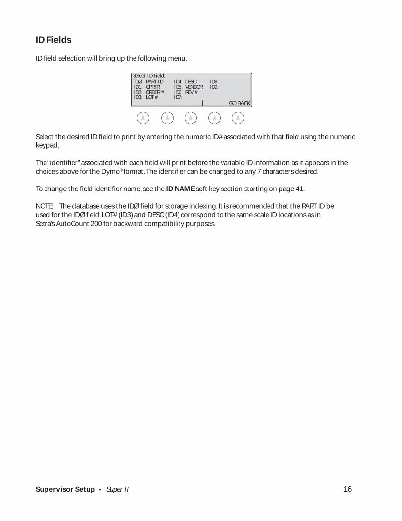
ID Fields
ID field selection will bring up the following menu.
Select the desired ID field to print by entering the numeric ID# associated with that field using the numerickeypad.
The “identifier” associated with each field will print before the variable ID information as it appears in thechoices above for the Dymo® format. The identifier can be changed to any 7 characters desired.
To change the field identifier name, see the ID NAME soft key section starting on page 41.
NOTE: The database uses the IDØ field for storage indexing. It is recommended that the PART ID beused for the IDØ field. LOT# (ID3) and DESC (ID4) correspond to the same scale ID locations as inSetra’s AutoCount 200 for backward compatibility purposes.
IDØ: PART ID ID4: DESC ID8: ID1: OPRTR ID5: VENDOR ID9: ID2: ORDER # ID6: REV # ID3: LOT # ID7:
GO BACK
Select ID Field:
Supervisor Setup • Super II 17
NO FRMT GO BACK
Select Format for Interval Printing: 0. Print 0 4. Print 4 8. Print 8 1. Print 1 5. Print 5 9. Print 9 2. Print 2 6. Print 6 –. Prt Int 3. Print 3 7. Print 7
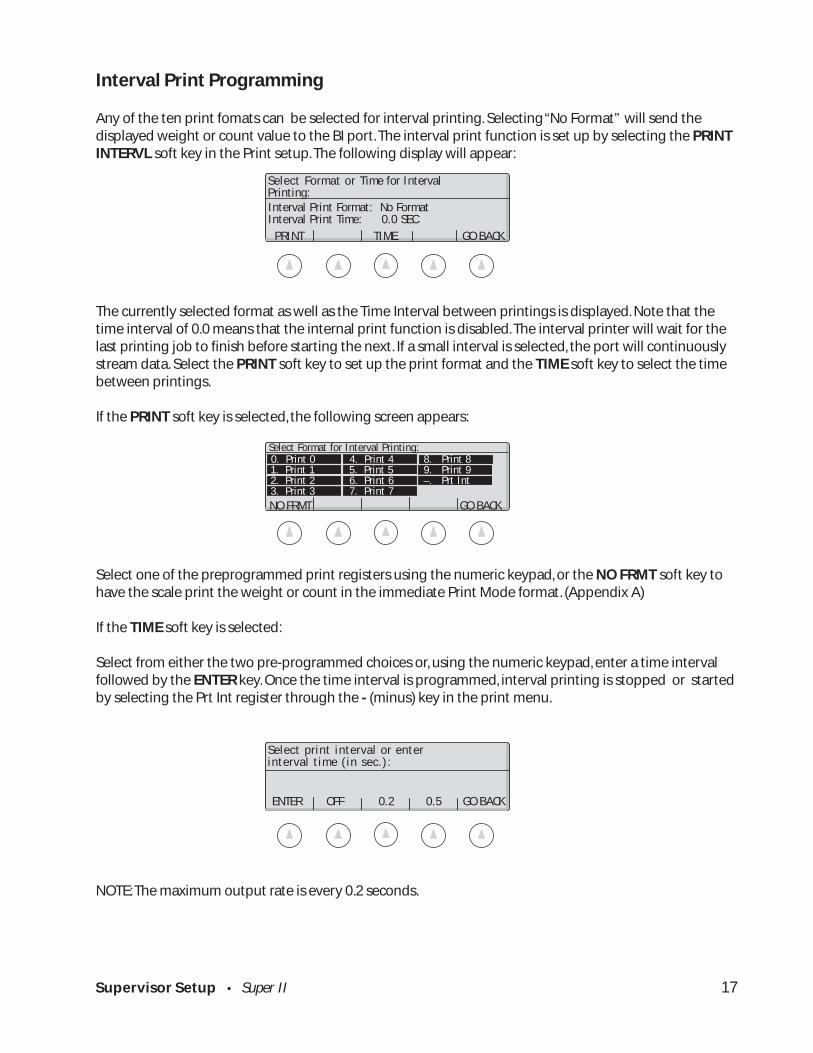
Interval Print Programming
Any of the ten print fomats can be selected for interval printing. Selecting “No Format” will send thedisplayed weight or count value to the BI port. The interval print function is set up by selecting the PRINTINTERVL soft key in the Print setup. The following display will appear:
The currently selected format as well as the Time Interval between printings is displayed. Note that thetime interval of 0.0 means that the internal print function is disabled. The interval printer will wait for thelast printing job to finish before starting the next. If a small interval is selected, the port will continuouslystream data. Select the PRINT soft key to set up the print format and the TIME soft key to select the timebetween printings.
If the PRINT soft key is selected, the following screen appears:
Select one of the preprogrammed print registers using the numeric keypad, or the NO FRMT soft key tohave the scale print the weight or count in the immediate Print Mode format. (Appendix A)
If the TIME soft key is selected:
Select from either the two pre-programmed choices or, using the numeric keypad, enter a time intervalfollowed by the ENTER key. Once the time interval is programmed, interval printing is stopped or startedby selecting the Prt Int register through the - (minus) key in the print menu.
NOTE: The maximum output rate is every 0.2 seconds.
ENTER OFF 0.2 0.5 GO BACK
Select print interval or enterinterval time (in sec.):
Select Format or Time for IntervalPrinting:
PRINT TIME GO BACK
Interval Print Format: No FormatInterval Print Time: 0.0 SEC
Supervisor Setup • Super II 18
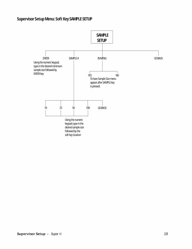
Supervisor Setup Menu: Soft Key SAMPLE SETUP
SAMPLE SETUP
ENTER SAMPLE # IN MENU GO BACKUsing the numeric keypad,type in the desired minimumsample size followed byENTER key
To have Sample Size menuappear after SAMPLE keyis pressed.
YES NO
10 25 50 100 GO BACK
Using the numerickeypad, type in thedesired sample sizefollowed by thesoft key location
Supervisor Setup • Super II 19
abc reset
menu remote
tare
SETUPS MORESUPERSETUP
SAMPLE SETUP
Soft Key:
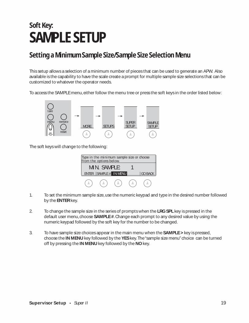
SAMPLE SETUPSetting a Minimum Sample Size/Sample Size Selection Menu
This setup allows a selection of a minimum number of pieces that can be used to generate an APW. Alsoavailable is the capability to have the scale create a prompt for multiple sample size selections that can becustomized to whatever the operator needs.
To access the SAMPLE menu, either follow the menu tree or press the soft keys in the order listed below:
The soft keys will change to the following:
1. To set the minimum sample size, use the numeric keypad and type in the desired number followedby the ENTER key.
2. To change the sample size in the series of prompts when the LRG SPL key is pressed in thedefault user menu, choose SAMPLE #. Change each prompt to any desired value by using thenumeric keypad followed by the soft key for the number to be changed.
3. To have sample size choices appear in the main menu when the SAMPLE > key is pressed,choose the IN MENU key followed by the YES key. The “sample size menu” choice can be turnedoff by pressing the IN MENU key followed by the NO key.
MIN. SAMPLE: 1
Type in the minimum sample size or choosefrom the options below.
ENTER SAMPLE # IN MENU GO BACK

Supervisor Setup • Super II 20
Supervisor Setup Menu: Soft Key ACCURCY SETUP
ACCURACY SETUP
ENTER 95% 98% 99% MOREUsing numeric keypad, type inthe desired minimum scaleperformance accuracy basedon sample weight followed bythe ENTER key
Selectedaccuracy
ENTER 99.5% 99.8% 99.9% GO BACK

Supervisor Setup • Super II 21
SETUPS MORESUPERSETUP
abc reset
tare
menu remote ACCURCY SETUP
Soft Key:
ACCURCY SETUPSetting a Minimum Scale Performance Accuracy
This setup allows selection of the minimum accuracy level to which the scale will perform based on thesample weight. The higher the scale performance, the larger the sample weight required. This may causethe scale to prompt for additional pieces when the COUNT key is pressed to meet the minimum weightrequirement to perform to the programmed accuracy level.
IMPORTANT: This setup does not take individual piece weight variance into account and only has to dowith sample weight. The scale must also be programmed with a large enough minimum sample size toguarantee performance based on piece weight variance.
To access the ACCURACY menu, either follow the menu tree or press the soft keys in the order listed below:
Using the numeric keypad, type in the desired Minimum Scale Performance Accuracy followed by theENTER key or choose from the soft key selections available and listed below.
Additional selections are available by pressing the MORE soft key.
Either type in the desired Minimum Scale Performance Accuracy followed by the ENTER soft key or choosefrom the selections available.
ENTER 95% 98% 99% MORE
Enter the minimum scale performanceaccuracy or select from the menu below:
ACCURACY 95.00
ENTER 99.5% 99.8% 99.9% GO BACK
Enter the minimum scale performanceaccuracy or select from the menu below:

Supervisor Setup • Super II 22
Supervisor Setup Menu: Soft Key PORTS SETUP
PORTSSETUP
BI* OUT IN GO BACK
B9600 B4800 B2400 B1200 GO BACK
8 NONE 7 ODD 7 EVEN GO BACK
ON OFF GO BACK
* Hardware handshaking available on the BI port only
Supervisor Setup • Super II 23
SETUPS MORESUPERSETUP
PORTSSETUP
abc reset
tare
menu remote
Soft Key:
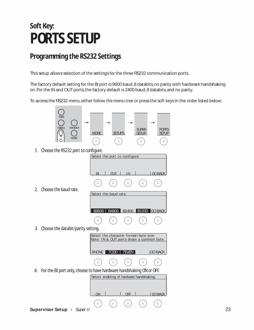
PORTS SETUPProgramming the RS232 Settings
This setup allows selection of the settings for the three RS232 communication ports.
The factory default setting for the BI port is 9600 baud, 8 databits, no parity with hardware handshakingon. For the IN and OUT ports, the factory default is 2400 baud, 8 databits, and no parity.
To access the RS232 menu, either follow the menu tree or press the soft keys in the order listed below:
1. Choose the RS232 port to configure.
2. Choose the baud rate.
3. Choose the databit/parity setting.
4. For the BI port only, choose to have hardware handshaking ON or OFF.
Select the baud rate:
B9600 B4800 B2400 B1200 GO BACK
BI OUT IN GO BACK
Select the port to configure:
Select the character format/byte size:Note: IN & OUT ports share a common byte
8NONE 7ODD 7EVEN GO BACK
ON OFF GO BACK
Select enabling of hardware handshaking:

Supervisor Setup • Super II 24
DATE TIME SET SET GO BACKFORMAT FORMAT DATE TIME
Enter date Enter time MM.DD.YY HH.MM
Supervisor Setup Menu: Soft Key TIME DATE
TIMEDATE
ENGLISH US NUM EUR NUM MILITARY SET DIG
2 DIGIT 4 DIGITYEAR YEAR
12 HR 24 HR AM PM 24 HR
Supervisor Setup • Super II 25
abc reset
menu remote
tare
SETUPS MORESUPERSETUP MORE
TIME DATE
Soft Key:
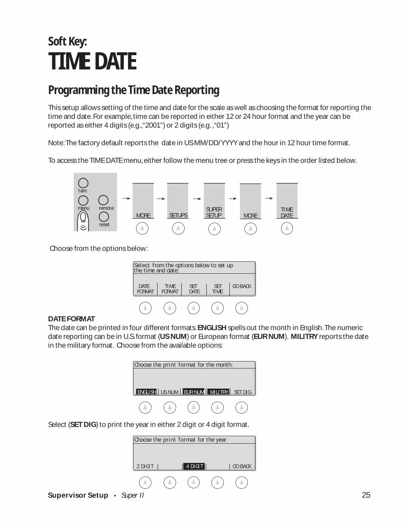
TIME DATEProgramming the Time Date ReportingThis setup allows setting of the time and date for the scale as well as choosing the format for reporting thetime and date. For example, time can be reported in either 12 or 24 hour format and the year can bereported as either 4 digits (e.g., “2001”) or 2 digits (e.g. , “01”)
Note: The factory default reports the date in US MM/DD/YYYY and the hour in 12 hour time format.
To access the TIME DATE menu, either follow the menu tree or press the keys in the order listed below.
Choose from the options below:
DATE FORMATThe date can be printed in four different formats. ENGLISH spells out the month in English. The numericdate reporting can be in U.S. format (US NUM) or European format (EUR NUM). MILITRY reports the datein the military format. Choose from the available options:
Select (SET DIG) to print the year in either 2 digit or 4 digit format.
DATE TIME SET SET GO BACK FORMAT FORMAT DATE TIME
Select from the options below to set upthe time and date:
Choose the print format for the year:
2 DIGIT 4 DIGIT GO BACK
Choose the print format for the month:
ENGLISH US NUM EUR NUM MILITRY SET DIG

Supervisor Setup • Super II 26
Set the date using the format MM.DD.YY
ENTER GO BACK
Select the display format for the time.
12 HR 24 HR GO BACK
Set the time using the format HH.MM
AM PM 24 HR GO BACK
TIME FORMATThe time can be printed in either 12 hour or 24 hour format. Choose from the options below:
SET DATEUsing the numeric keypad, type in the date in the format, MM.DD.YY, followed by the ENTER key:
SET TIMEUsing the numeric keypad, type in the time in the format, HH.MM, followed by a selection for AM, PM, or24 HR key.
Supervisor Setup • Super II 27
Supervisor Setup Menu: Soft Key UNITS ENABLED
Enter name for Enter resolution user definable unit for last digit for
user definable unit
CONVERSION NAME RESOLUTION ON/OFF GO BACK
UNITSENABLED
GRAMS OZ LBS DWT MORE
TROY OZ CARATS KG GRAINS GO BACK
FACTOR DIVISOR GO BACK

Supervisor Setup • Super II 28
SETUPS MORESUPERSETUP
abc reset
tare
menu remote UNITS ENABLED MORE
Soft Key:
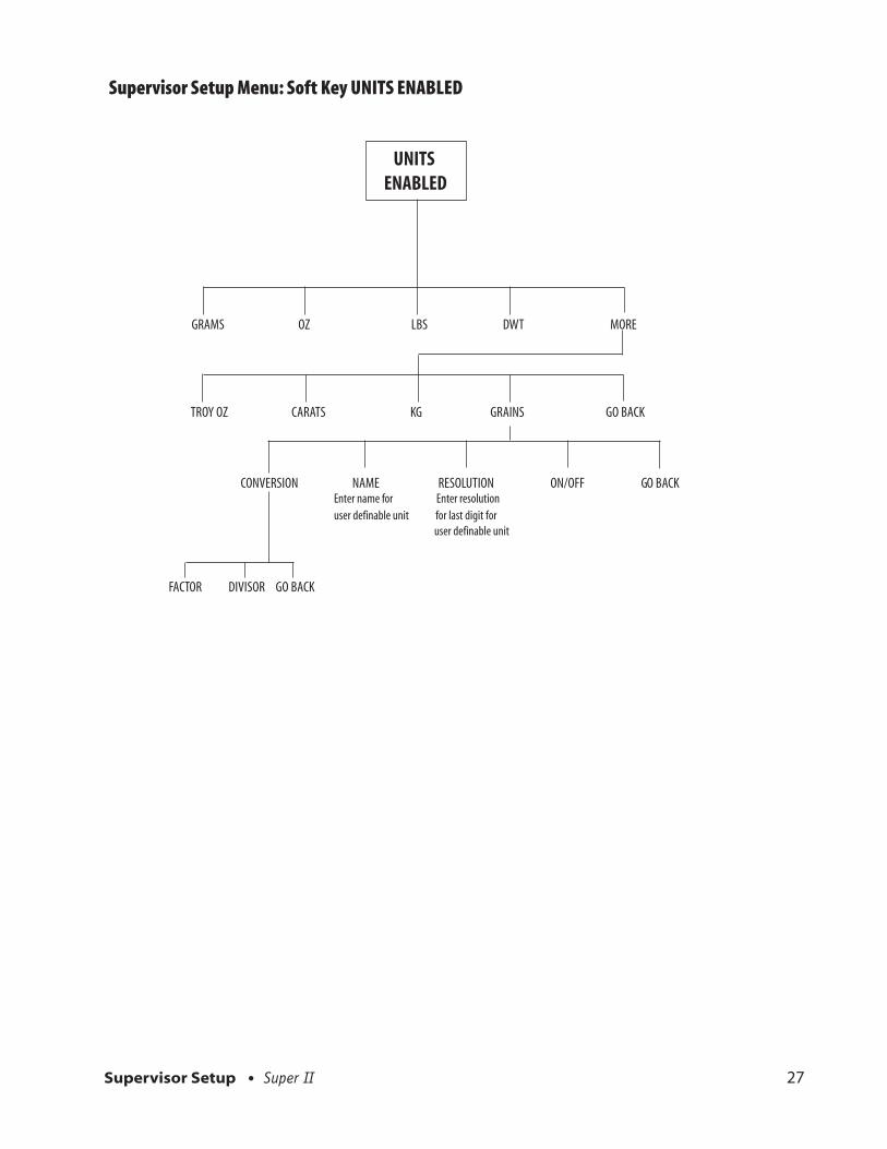
UNITS ENABLEDSelecting Weighing UnitsThis setup allows selection of units of measure available in the UNITS soft key menu in the User Functions(See User’s Manual). In addition, the last unit of measure (GRAINS) is a user definable unit of measure,sometimes referred to as ‘x’units. For the user definable unit, the conversion factor, the resolution and thename of the unit can be customized.
Note: The factory default is to have all units available and the user definable unit set to GRAINS.
To access the UNITS ENABLED menu, either follow the menu tree or press the keys in the order listedbelow:GRAMS
1. To toggle the availability of a unit of measure, select that unit of measure. Units that are not available to theuser are shown in reverse video.
GRAMS OZ LBS DWT MORE
Enable/Disable units or Programx units. Select from the menu below:
TROY OZ CARATS KG GRAINS GO BACK
Enable/Disable units or Programx units. Select from the menu below:
Supervisor Setup • Super II 29
Enter the details of the selected unit:
CONVRSN NAME RESOLUT ON/OFF GO BACK
FACTOR DIVISOR GO BACK
Enter the conversion factor (x) ordivisor (/) from grams:
ENTER GO BACK
Enter the unit name:
Enter the details of the selected unit:
CONVRSN NAME RESOLUT ON/OFF GO
ENTER GO BACK
Enter the resolution of the last digit:
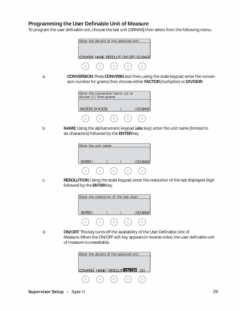
Programming the User Definable Unit of MeasureTo program the user definable unit, choose the last unit (GRAINS) then select from the following menu:
a. CONVERSION: Press CONVRSN and then, using the scale keypad, enter the conver-sion number for grams; then choose either FACTOR (multiplier) or DIVISOR.
b. NAME: Using the alphanumeric keypad (abc key), enter the unit name (limited tosix characters) followed by the ENTER key.
c. RESOLUTION: Using the scale keypad, enter the resolution of the last displayed digitfollowed by the ENTER key.
d. ON/OFF: This key turns off the availability of the User Definable Unit ofMeasure. When the ON/OFF soft key appears in reverse video, the user definable unitof measure is unavailable.
Supervisor Setup • Super II 30
Supervisor Setup Menu: Soft Key DATBASE SETUP
DATABASESETUP
PART ID, APW, TARE PART ID, LOT #, APW PART ID, APW, ACC CT PART ID, LOW, TARGET, HIGH1 2 3 4 MORE
5 6 GO BACKFULL DATABASE DATABASE OFF
FORMAT TRANSFR SECURTY
LOCKOLD NO LOCK LOCKALL GO BACK
BI OUT GO BACK
DATBASE PRINT DATBASE GO BACK
Supervisor Setup • Super II 31
SETUPS MORESUPERSETUP
abc reset
tare
menu remote DATBASE SETUP MORE
Soft Key:
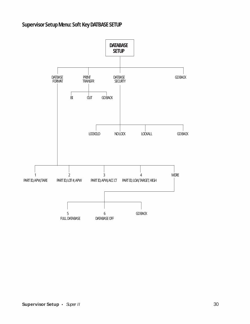
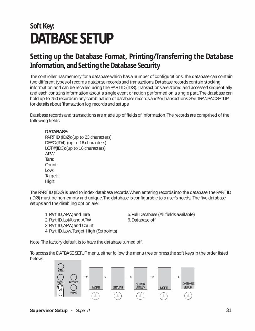
DATBASE SETUPSetting up the Database Format, Printing/Transferring the DatabaseInformation, and Setting the Database SecurityThe controller has memory for a database which has a number of configurations. The database can containtwo different types of records: database records and transactions. Database records contain stockinginformation and can be recalled using the PART ID (IDØ). Transactions are stored and accessed sequentiallyand each contains information about a single event or action performed on a single part. The database canhold up to 750 records in any combination of database records and/or transactions. See TRANSAC SETUPfor details about Transaction log records and setups.
Database records and transactions are made up of fields of information. The records are comprised of thefollowing fields:
DATABASE:PART ID (IDØ): (up to 23 characters)DESC (ID4): (up to 16 characters)LOT #(ID3): (up to 16 characters)APWTare:Count:Low:Target:High:
The PART ID (IDØ) is used to index database records. When entering records into the database, the PART ID(IDØ) must be non-empty and unique. The database is configurable to a user’s needs. The five databasesetups and the disabling option are:
1. Part ID, APW, and Tare 5. Full Database (All fields available)2. Part ID, Lot#, and APW 6. Database off3. Part ID, APW, and Count4. Part ID, Low, Target, High (Setpoints)
Note: The factory default is to have the database turned off.
To access the DATBASE SETUP menu, either follow the menu tree or press the soft keys in the order listedbelow:

Supervisor Setup • Super II 32
DATBASE PRINT DATBASE GO BACK FORMAT TRANSFR SECURTY
Select database setup option:
5 6 GO BACK
5. FULL DATABASE6. DATABASE OFF
Choose the fields in your database:
BI OUT GO BACK
Select the port for the printer output.
1 2 3 4 MORE
Choose the fields in the database:1. PART ID, APW, TARE2. PART ID, LOT #, and APW3. PART ID, APW, ACC CT4. PART ID, LOW, TARGET, HIGH
The following menu is displayed and the soft keys change to:
Select the DATBASE FORMAT soft key for programming the database format. The following menu andsoft keys appear:
Select the desired database format by pressing the soft key for the number corresponding to thefields to be stored and automatically retrieved through the use of the PART ID field.
To have all of the database fields available or to turn off access to the database, press the MOREsoft key followed by the number corresponding to the desired selection:
Select the PRINT TRANSFER soft key to send the database records through the RS-232 Port.The following menu and soft keys appear:
Select BI to transmit the database records through the Bi-directional Port, or OUT to send the recordsthrough the output only port.
Supervisor Setup • Super II 33
Select the database protection from themenu below:
LOCK OLD NO LOCK LOCK ALL GO BACK
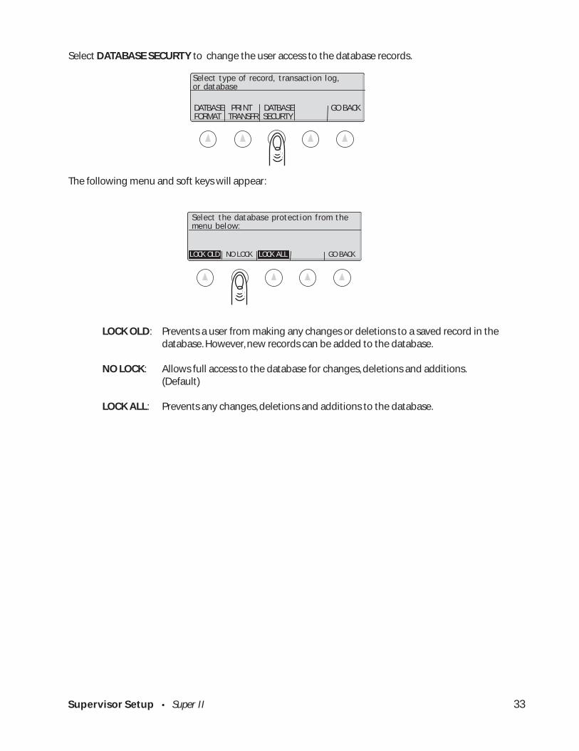
Select DATABASE SECURTY to change the user access to the database records.
The following menu and soft keys will appear:
LOCK OLD: Prevents a user from making any changes or deletions to a saved record in thedatabase. However, new records can be added to the database.
NO LOCK: Allows full access to the database for changes, deletions and additions.(Default)
LOCK ALL: Prevents any changes, deletions and additions to the database.
DATBASE PRINT DATBASE GO BACK FORMAT TRANSFR SECURTY
Select type of record, transaction log,or database
Supervisor Setup • Super II 34
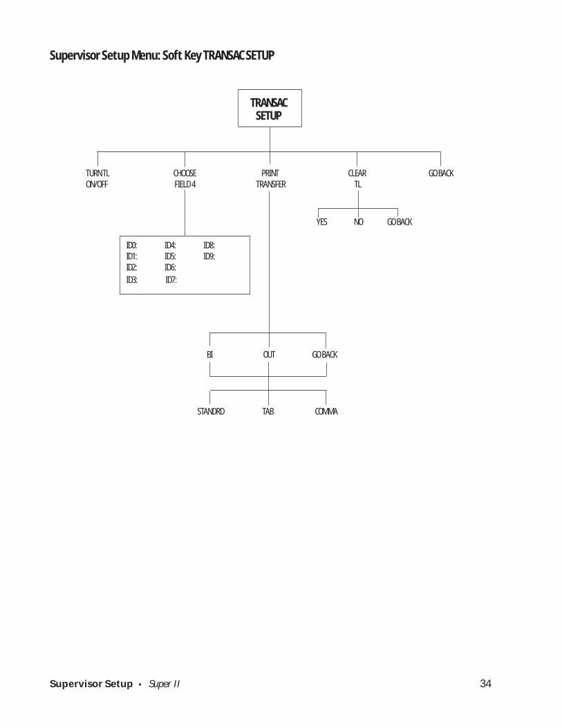
TURN TL CHOOSE PRINT CLEAR GO BACKON/OFF FIELD 4 TRANSFER TL
Supervisor Setup Menu: Soft Key TRANSAC SETUP
TRANSACSETUP
BI OUT GO BACK
YES NO GO BACK
ID0: ID4: ID8:ID1: ID5: ID9:ID2: ID6:
ID3: ID7:
STANDRD TAB COMMA
Supervisor Setup • Super II 35
SETUPS MORESUPERSETUP
abc reset
tare
menu remote TRANSAC SETUP MORE
Select TL fields using the numeric keys: 1. PART ID 4. OPRTR 2. LOT # 5. COUNT 3. DESC. 6. TIME/DATETURN TL CHOOSE PRINT CLEAR GO BACKON/OFF FIELD 4 TRANSFR TL
Soft Key:
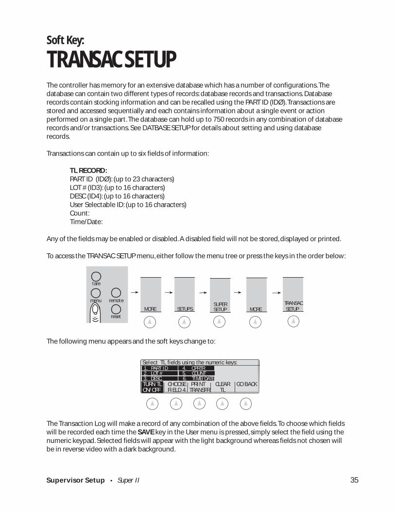
TRANSAC SETUPThe controller has memory for an extensive database which has a number of configurations. Thedatabase can contain two different types of records: database records and transactions. Databaserecords contain stocking information and can be recalled using the PART ID (IDØ). Transactions arestored and accessed sequentially and each contains information about a single event or actionperformed on a single part. The database can hold up to 750 records in any combination of databaserecords and/or transactions. See DATBASE SETUP for details about setting and using databaserecords.
Transactions can contain up to six fields of information:
TL RECORD:PART ID (IDØ): (up to 23 characters)LOT # (ID3): (up to 16 characters)DESC (ID4): (up to 16 characters)User Selectable ID: (up to 16 characters)Count:Time/Date:
Any of the fields may be enabled or disabled. A disabled field will not be stored, displayed or printed.
To access the TRANSAC SETUP menu, either follow the menu tree or press the keys in the order below:
The following menu appears and the soft keys change to:
The Transaction Log will make a record of any combination of the above fields. To choose which fieldswill be recorded each time the SAVE key in the User menu is pressed, simply select the field using thenumeric keypad. Selected fields will appear with the light background whereas fields not chosen willbe in reverse video with a dark background.
Supervisor Setup • Super II 36
Select TL fields using the numeric keys: 1. PART ID 4. OPRTR 2. LOT # 5. COUNT 3. DESC. 6. TIME/DATETURN TL CHOOSE PRINT CLEAR GO BACK ON FIELD 4 TRANSFR TL
Select TL fields using the numeric keys: 1. PART ID 4. OPRTR 2. LOT # 5. COUNT 3. DESC. 6. TIME/DATETURN TL CHOOSE PRINT CLEAR GO BACKON/OFF FIELD 4 TRANSFR TL
Select TL fields using the numeric keys: 1. PART ID 4. OPRTR 2. LOT # 5. COUNT 3. DESC. 6. TIME/DATETURN TL CHOOSE PRINT CLEAR GO BACKON/OFF FIELD 4 TRANSFR TL
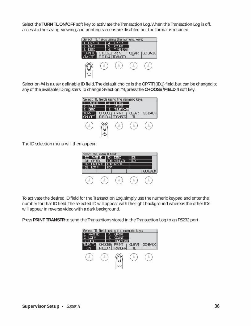
Select the TURN TL ON/OFF soft key to activiate the Transaction Log. When the Transaction Log is off,access to the saving, viewing, and printing screens are disabled but the format is retained.
Selection #4 is a user definable ID field. The default choice is the OPRTR (ID1) field, but can be changed toany of the available ID registers. To change Selection #4, press the CHOOSE /FIELD 4 soft key.
The ID selection menu will then appear:
To activate the desired ID field for the Transaction Log, simply use the numeric keypad and enter thenumber for that ID field. The selected ID will appear with the light background whereas the other IDswill appear in reverse video with a dark background.
Press PRINT TRANSFR to send the Transactions stored in the Transaction Log to an RS232 port.
Select the extra Tl field:
GO BACK
IDØ: PART ID ID4: DESC ID8: ID1: OPRTR ID5: VENDOR ID9: ID2: ORDER # ID6: REV # ID3: LOT # ID7:
Supervisor Setup • Super II 37
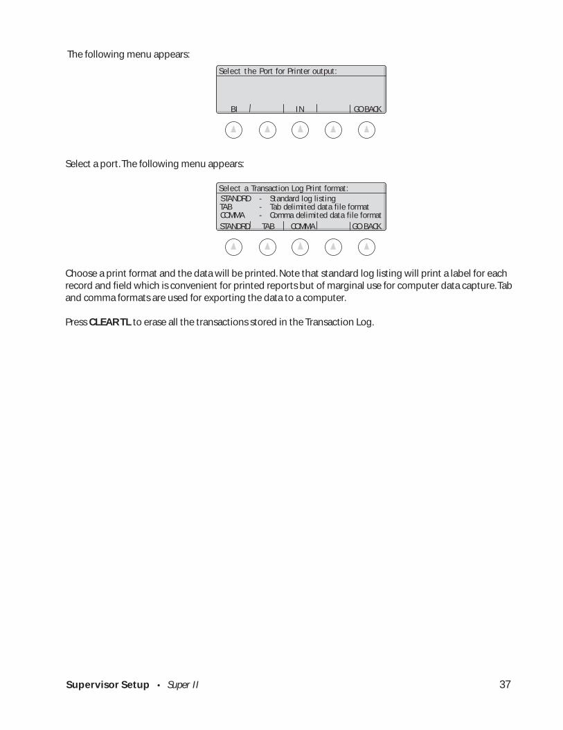
The following menu appears:
Select a port. The following menu appears:
Choose a print format and the data will be printed. Note that standard log listing will print a label for eachrecord and field which is convenient for printed reports but of marginal use for computer data capture. Taband comma formats are used for exporting the data to a computer.
Press CLEAR TL to erase all the transactions stored in the Transaction Log.
BI IN GO BACK
Select the Port for Printer output:
STANDRD TAB COMMA GO BACK
Select a Transaction Log Print format: STANDRD - Standard log listing TAB - Tab delimited data file format COMMA - Comma delimited data file format

Supervisor Setup • Super II 38
Supervisor Setup Menu: Soft Key ID NAME SETUP
ID NAMESETUP
ID0: PART ID ID4: DESC ID8:ID1: OPRTR ID5: VENDOR ID9:ID2: ORDER # ID6: REV #
ID3: LOT # ID7:
GO BACK
Supervisor Setup • Super II 39
Soft Key:
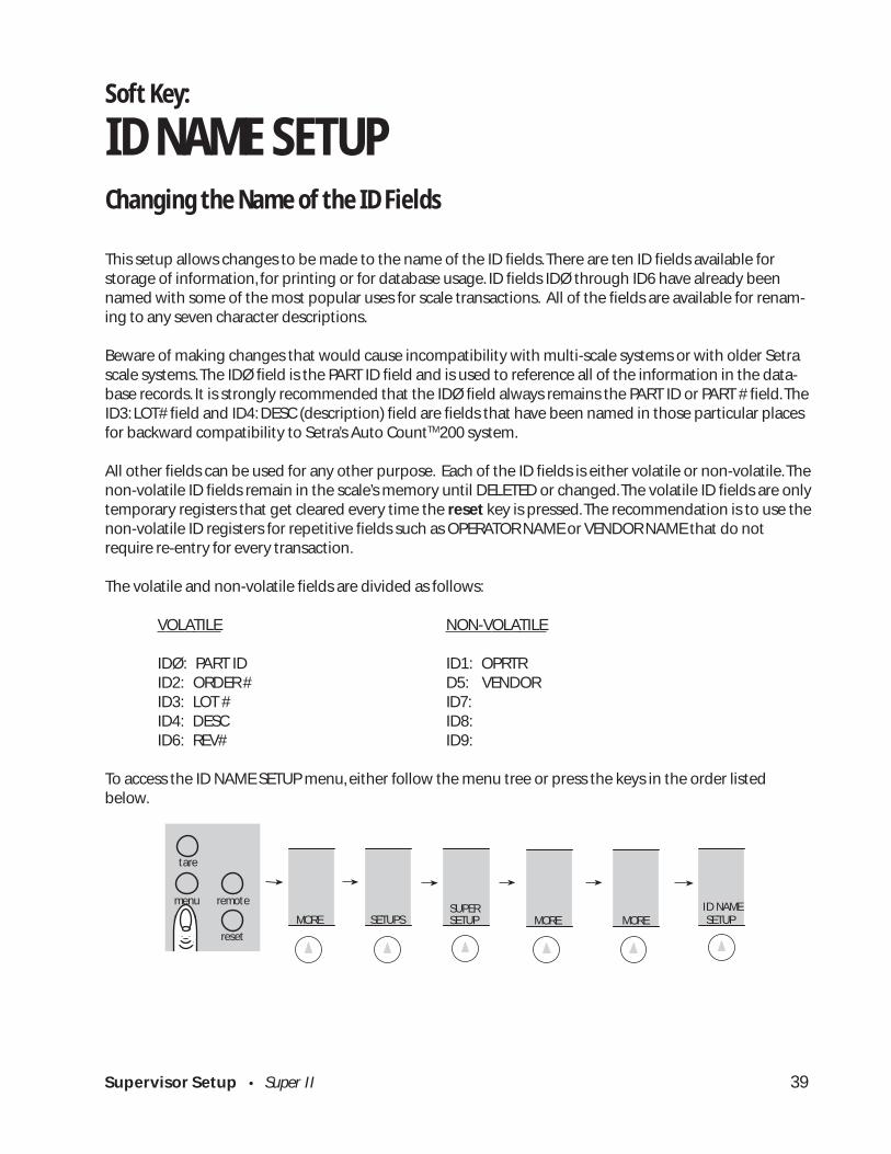
ID NAME SETUPChanging the Name of the ID Fields
This setup allows changes to be made to the name of the ID fields. There are ten ID fields available forstorage of information, for printing or for database usage. ID fields IDØ through ID6 have already beennamed with some of the most popular uses for scale transactions. All of the fields are available for renam-ing to any seven character descriptions.
Beware of making changes that would cause incompatibility with multi-scale systems or with older Setrascale systems. The IDØ field is the PART ID field and is used to reference all of the information in the data-base records. It is strongly recommended that the IDØ field always remains the PART ID or PART # field. TheID3: LOT# field and ID4: DESC (description) field are fields that have been named in those particular placesfor backward compatibility to Setra’s Auto CountTM200 system.
All other fields can be used for any other purpose. Each of the ID fields is either volatile or non-volatile. Thenon-volatile ID fields remain in the scale’s memory until DELETED or changed. The volatile ID fields are onlytemporary registers that get cleared every time the reset key is pressed. The recommendation is to use thenon-volatile ID registers for repetitive fields such as OPERATOR NAME or VENDOR NAME that do notrequire re-entry for every transaction.
The volatile and non-volatile fields are divided as follows:
VOLATILE NON-VOLATILE
IDØ: PART ID ID1: OPRTRID2: ORDER # D5: VENDORID3: LOT # ID7:ID4: DESC ID8:ID6: REV# ID9:
To access the ID NAME SETUP menu, either follow the menu tree or press the keys in the order listedbelow.
SETUPS MORESUPERSETUP
abc reset
tare
menu remote ID NAME SETUP MORE MORE

Supervisor Setup • Super II 40
The following menu will appear:
Using the numeric keypad, enter the number of the desired ID field name to be changed.
Using the alphanumeric keypad (abc key) or PC keyboard, enter up to 7 characters of the new name forthe ID field followed by the ENTER soft key.
ENTER GO BACK
Enter new name, followed by the Enter.
IDØ: PART ID ID4: DESC ID8: ID1: OPRTR ID5: VENDOR ID9: ID2: ORDER # ID6: REV # ID3: LOT # ID7:
GO BACK
Select ID Field to Name:

Supervisor Setup • Super II 41
Supervisor Setup Menu: Soft Key MACRO SETUP
0. Macro 4. Macro 4 8. Macro 81. Macro 1 5. Macro 5 9. Example2. Macro 2 6. Macro 63. Macro 3 7. Macro 2
NAME/ MACRO DELETE PROGRAM GO BACK RENAME ON/OFF FORMAT MACRO
MACROSETUP
PREV NEXT SELECT GO BACK DONEto move up in list to move down in list
ZERO COUNT CLEAR PRINT ADD CT SET PTS X UNIT
TARE APW ID NEXT SUB CT LOW Y UNIT
TARE WT END CT RECL DB ACCUM BASE TARGET UNITS
SAMP/CT RESTART RESET SAVE DB SAVE TL HIGH EXIT
CUSTOM STANDARD AUTOMATE GO BACKPROMPT PROMPT STEP
to write and use a to use the default prompt to automate the stepnew prompt up to without a prompt
80 characters

Supervisor Setup • Super II 42
SETUPS MORESUPERSETUP
abc reset
tare
menu remote MACRO SETUP MORE MORE
GO BACK
0. Macro 0 4. Macro 4 8. Macro 8 1. Macro 1 5. Macro 5 9. EXAMPLE 2. Macro 2 6. Macro 6 3. Macro 3 7. Macro 7
Select the Macro script to edit:
Soft Key:
MACRO SETUPCustomizing Scale Operation & Prompting SequencesThis setup allows creation of a custom scale operation sequence. A macro step can either use the standardprompt or a custom prompt. The prompts are limited to 80 characters on two lines. The scale functionnames cannot be changed.
Each macro is comprised of a series of steps. A step has an operation that the scale performs (selectablefrom a list during macro programming) and a prompt to the user.
There are two modes of operation of the macro:
1. If only Macro Ø is enabled, it will be the scale’s DEFAULT as the first and only operation available onpower-up, using the soft keys (except for going into the menu system).
2. If macros other than Macro Ø ‚ are enabled, they will be available when the MACRO SETUP softkey is pressed while in the scale’s normal default operating mode. If more than one macro isenabled, a menu selection will appear.
To access the MACRO SETUP menu either follow the menu tree or press the keys in the order listed below:
The following menu appears:
Using the numeric keypad, select the Macro (Ø-9) to edit. If the macro is to be the scale’s DEFAULT, place itin Macro Ø. Please note that if Macro Ø is the only macro active, it will automatically become the scale’sdefault operation. If only one macro is programmed and it is not to become the scale’s default operation,place it in Macro 1 - 9.
Supervisor Setup • Super II 43
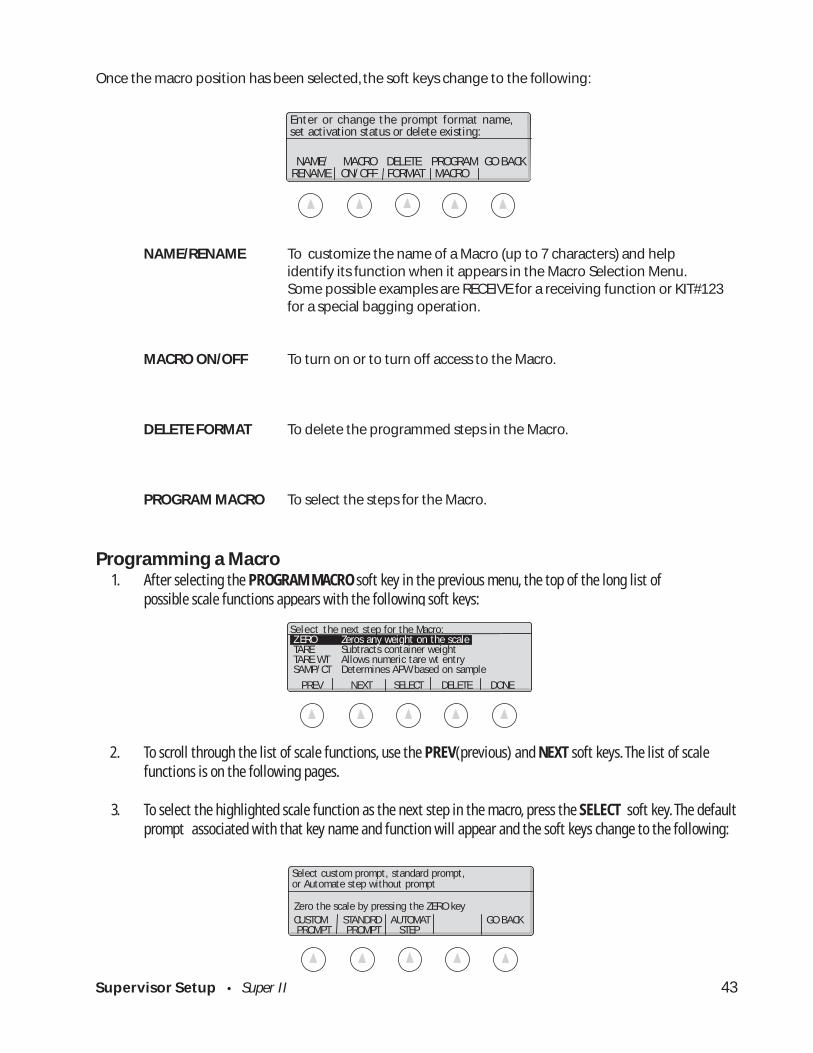
Once the macro position has been selected, the soft keys change to the following:
NAME/RENAME To customize the name of a Macro (up to 7 characters) and helpidentify its function when it appears in the Macro Selection Menu.Some possible examples are RECEIVE for a receiving function or KIT#123for a special bagging operation.
MACRO ON/OFF To turn on or to turn off access to the Macro.
DELETE FORMAT To delete the programmed steps in the Macro.
PROGRAM MACRO To select the steps for the Macro.
Programming a Macro1. After selecting the PROGRAM MACRO soft key in the previous menu, the top of the long list of
possible scale functions appears with the following soft keys:
2. To scroll through the list of scale functions, use the PREV(previous) and NEXT soft keys. The list of scalefunctions is on the following pages.
3. To select the highlighted scale function as the next step in the macro, press the SELECT soft key. The defaultprompt associated with that key name and function will appear and the soft keys change to the following:
Zero the scale by pressing the ZERO key
Select custom prompt, standard prompt,or Automate step without prompt
CUSTOM STANDRD AUTOMAT GO BACK PROMPT PROMPT STEP
NAME/ MACRO DELETE PROGRAM GO BACK RENAME ON/OFF FORMAT MACRO
Enter or change the prompt format name,set activation status or delete existing:
Select the next step for the Macro:Z ERO Zeros any weight on the scaleTARE Subtracts container weightTARE WT Allows numeric tare wt entrySAMP/CT Determines APW based on sample
PREV NEXT SELECT DELETE DONE
Supervisor Setup • Super II 44
A. To use the default prompt, press the STANDRD PROMPT soft key and the program will return to thescale function selection menu (step 1).
B. To program a custom prompt associated with that key name and function, press the CUSTOMPROMPT soft key. The menu will change; type in a prompt of up to 80 characters using the scale’salphanumeric keypad (abc key) or an attached QWERTY keyboard.
C. To automate the step without a prompt, press the AUTOMAT STEP soft key. An automated step willprocess the scale function without waiting for user input.
4. To erase the last selected step in the macro, press the DELETE soft key. If all the steps are erased, the previousscreen is displayed.
5. After selecting the last step in the macro, press the DONE soft key.
Supervisor Setup • Super II 45
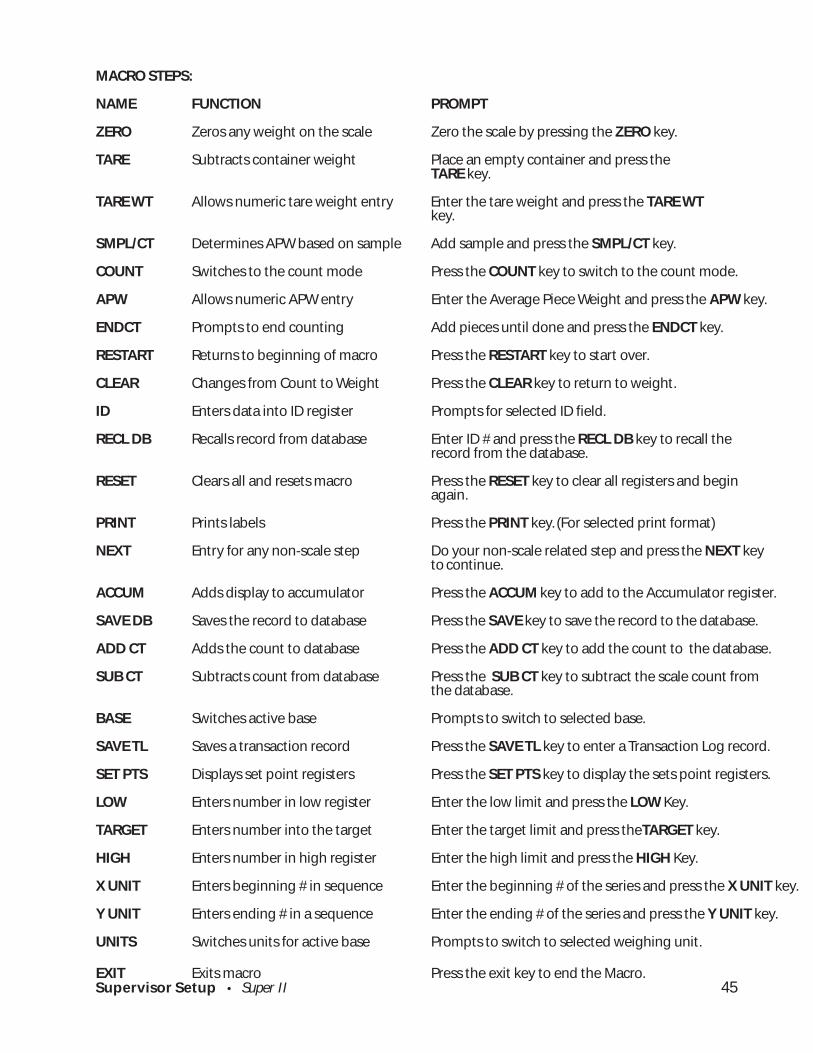
MACRO STEPS:
NAME FUNCTION PROMPT
ZERO Zeros any weight on the scale Zero the scale by pressing the ZERO key.
TARE Subtracts container weight Place an empty container and press theTARE key.
TARE WT Allows numeric tare weight entry Enter the tare weight and press the TARE WTkey.
SMPL/CT Determines APW based on sample Add sample and press the SMPL/CT key.
COUNT Switches to the count mode Press the COUNT key to switch to the count mode.
APW Allows numeric APW entry Enter the Average Piece Weight and press the APW key.
ENDCT Prompts to end counting Add pieces until done and press the ENDCT key.
RESTART Returns to beginning of macro Press the RESTART key to start over.
CLEAR Changes from Count to Weight Press the CLEAR key to return to weight.
ID Enters data into ID register Prompts for selected ID field.
RECL DB Recalls record from database Enter ID # and press the RECL DB key to recall therecord from the database.
RESET Clears all and resets macro Press the RESET key to clear all registers and beginagain.
PRINT Prints labels Press the PRINT key. (For selected print format)
NEXT Entry for any non-scale step Do your non-scale related step and press the NEXT keyto continue.
ACCUM Adds display to accumulator Press the ACCUM key to add to the Accumulator register.
SAVE DB Saves the record to database Press the SAVE key to save the record to the database.
ADD CT Adds the count to database Press the ADD CT key to add the count to the database.
SUB CT Subtracts count from database Press the SUB CT key to subtract the scale count fromthe database.
BASE Switches active base Prompts to switch to selected base.
SAVE TL Saves a transaction record Press the SAVE TL key to enter a Transaction Log record.
SET PTS Displays set point registers Press the SET PTS key to display the sets point registers.
LOW Enters number in low register Enter the low limit and press the LOW Key.
TARGET Enters number into the target Enter the target limit and press theTARGET key.
HIGH Enters number in high register Enter the high limit and press the HIGH Key.
X UNIT Enters beginning # in sequence Enter the beginning # of the series and press the X UNIT key.
Y UNIT Enters ending # in a sequence Enter the ending # of the series and press the Y UNIT key.
UNITS Switches units for active base Prompts to switch to selected weighing unit.
EXIT Exits macro Press the exit key to end the Macro.
Supervisor Setup • Super II 46
GO BACK
Select the base to switch to. 1. Base 1 5. Base 5 2. Base 2 6. Base 6 3. Base 3 7. Base 7 4. Base 4 8. Base 8
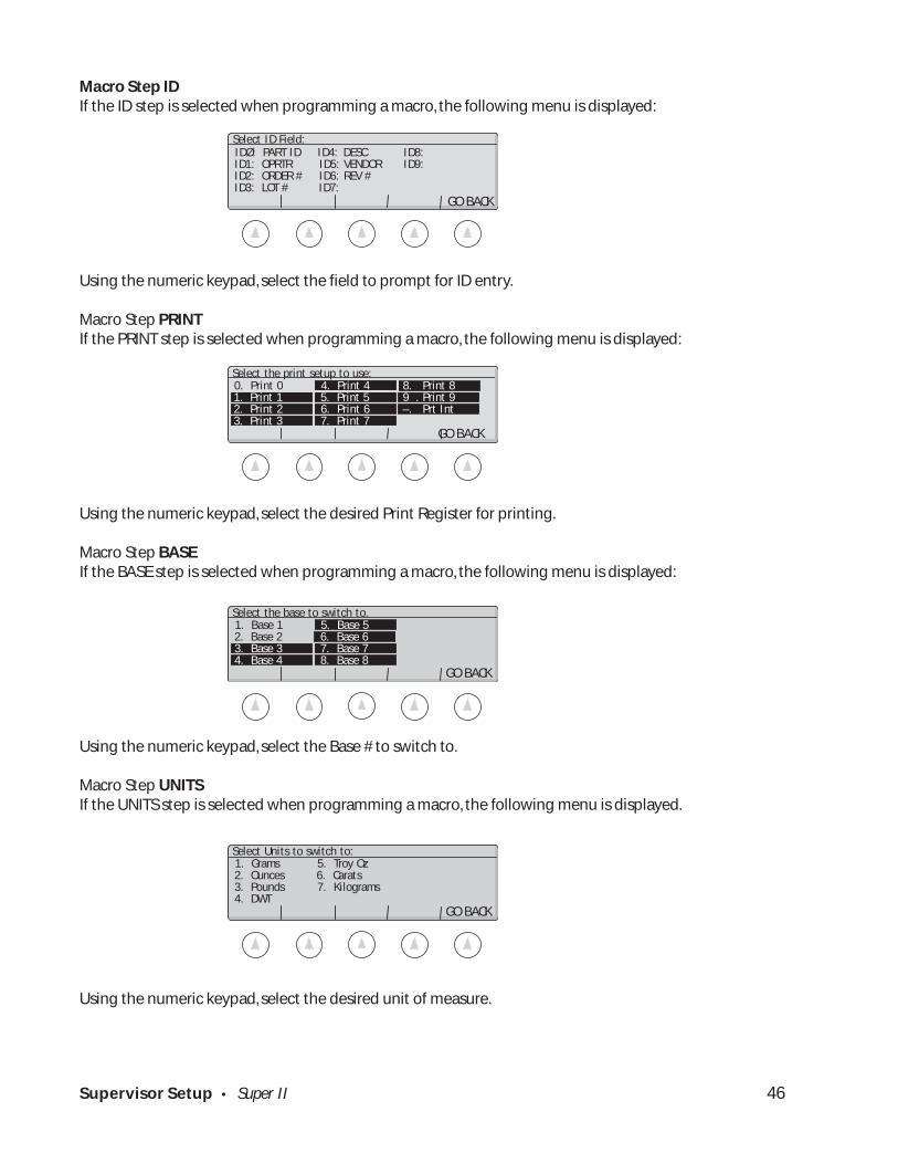
Macro Step IDIf the ID step is selected when programming a macro, the following menu is displayed:
Using the numeric keypad, select the field to prompt for ID entry.
Macro Step PRINTIf the PRINT step is selected when programming a macro, the following menu is displayed:
Using the numeric keypad, select the desired Print Register for printing.
Macro Step BASEIf the BASE step is selected when programming a macro, the following menu is displayed:
Using the numeric keypad, select the Base # to switch to.
Macro Step UNITSIf the UNITS step is selected when programming a macro, the following menu is displayed.
Using the numeric keypad, select the desired unit of measure.
1. Grams 5. Troy Oz 2. Ounces 6. Carats 3. Pounds 7. Kilograms 4. DWT GO BACK
Select Units to switch to:
IDØ: PART ID ID4: DESC ID8: ID1: OPRTR ID5: VENDOR ID9: ID2: ORDER # ID6: REV # ID3: LOT # ID7:
GO BACK
Select ID Field:
0. Print 0 4. Print 4 8. Print 8 1. Print 1 5. Print 5 9 . Print 9 2. Print 2 6. Print 6 –. Prt Int 3. Print 3 7. Print 7
GO BACK
Select the print setup to use:

Supervisor Setup • Super II 47
Supervisor Setup Menu: Soft Key SETUP SECURTY
SETUPSECURITY
ENTER GO BACK

Supervisor Setup • Super II 48
Soft Key:
SETUP SECURTY
Setting Supervisor Password ProtectionThis setup allows the set up of password protection for the Supervisor Setup menu.
To access the SETUP SECURITY menu, either follow the menu tree or press the keys in the order listedbelow:
A password up to 10 characters in length can be typed in using the alphanumeric keypad (abc key)followed by the ENTER soft key.
ex: Type XYZ 123 followed by ENTER
If the ENTER soft key is pressed without entering any characters, password protection is canceled.
Note: Password is case sensitive.
SETUPS MORESUPERSETUP
abc reset
tare
menu remote SETUPSECURTY MORE MORE

Supervisor Setup • Super II 49
Supervisor Setup Menu: Soft Key BEEPER CONTROL
BEEPERCONTROL
ON OFF GO BACK

Supervisor Setup • Super II 50
SETUPS MORESUPERSETUP
abc reset
tare
menu remote
MORE MORE MORE BEEPER CONTROL
Soft Key:
BEEPER CONTROL
Setting the Beeper to ON and OFF
To access the Beeper Control menu, either follow the menu tree or press the keys in the order listed below:
The following menu appears:
Select the ON soft key to enable the beeper and the OFF to disable the beeper.
Select if Beeper is enabled:
ON OFF GO BACK

Bases Setup • Super II 51
Bases Setup
Bases Setup • Super II 52
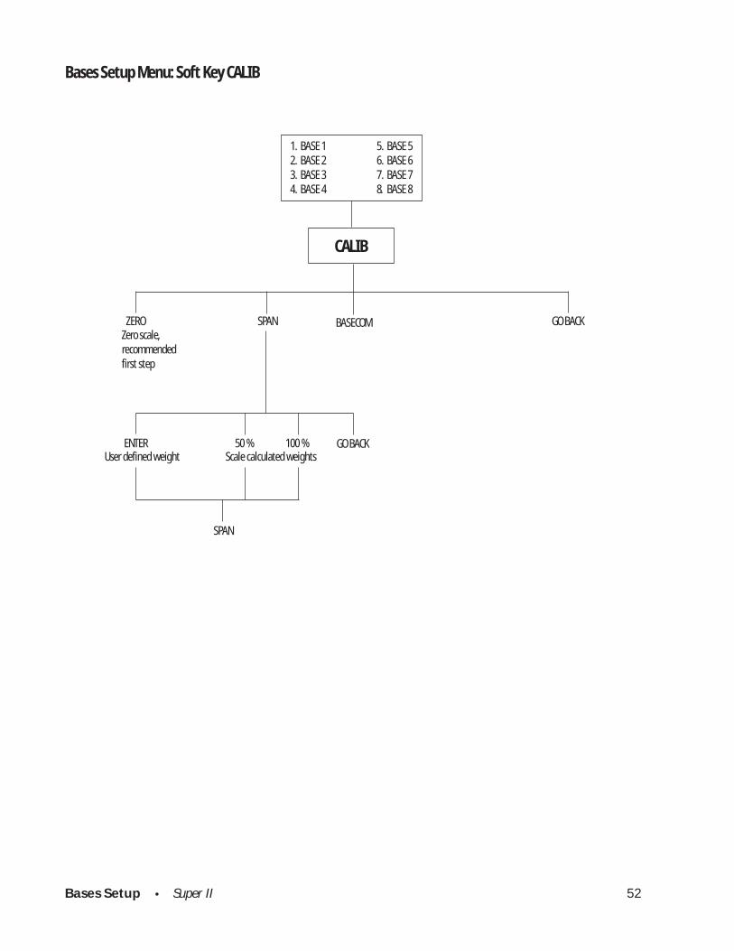
Bases Setup Menu: Soft Key CALIB
CALIB
ZERO SPAN GO BACK Zero scale,
recommendedfirst step
ENTER 50 % 100 %
SPAN
GO BACKUser defined weight Scale calculated weights
BASECOM
1. BASE 1 5. BASE 52. BASE 2 6. BASE 63. BASE 3 7. BASE 74. BASE 4 8. BASE 8
Bases Setup • Super II 53
SETUPS MOREBASESSETUP CALIB
abc reset
tare
menu remote
Base 1
Grams
Select calibration option:
ZERO SPAN BASECOM GO BACK0.00
Soft Key:
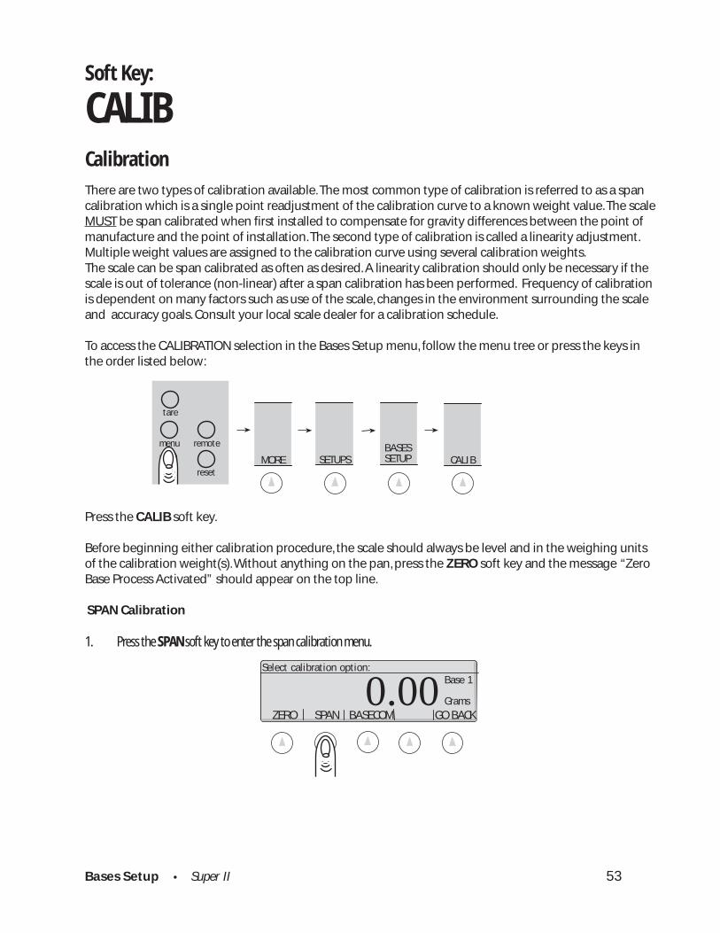
CALIBCalibration
There are two types of calibration available. The most common type of calibration is referred to as a spancalibration which is a single point readjustment of the calibration curve to a known weight value. The scaleMUST be span calibrated when first installed to compensate for gravity differences between the point ofmanufacture and the point of installation. The second type of calibration is called a linearity adjustment.Multiple weight values are assigned to the calibration curve using several calibration weights.The scale can be span calibrated as often as desired. A linearity calibration should only be necessary if thescale is out of tolerance (non-linear) after a span calibration has been performed. Frequency of calibrationis dependent on many factors such as use of the scale, changes in the environment surrounding the scaleand accuracy goals. Consult your local scale dealer for a calibration schedule.
To access the CALIBRATION selection in the Bases Setup menu, follow the menu tree or press the keys inthe order listed below:
Press the CALIB soft key.
Before beginning either calibration procedure, the scale should always be level and in the weighing unitsof the calibration weight(s). Without anything on the pan, press the ZERO soft key and the message “ZeroBase Process Activated” should appear on the top line.
SPAN Calibration
1. Press the SPAN soft key to enter the span calibration menu.
Bases Setup • Super II 54
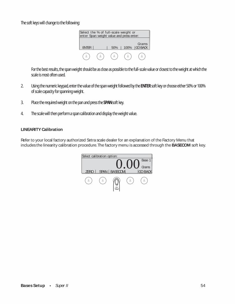
The soft keys will change to the following:
For the best results, the span weight should be as close as possible to the full-scale value or closest to the weight at which thescale is most often used.
2. Using the numeric keypad, enter the value of the span weight followed by the ENTER soft key or choose either 50% or 100%of scale capacity for spanning weight.
3. Place the required weight on the pan and press the SPAN soft key.
4. The scale will then perform a span calibration and display the weight value.
LINEARITY Calibration
Refer to your local factory authorized Setra scale dealer for an explanation of the Factory Menu thatincludes the linearity calibration procedure. The factory menu is accessed through the BASECOM soft key.
ENTER 50% 100% GO BACK
Select the % of full-scale weight orenter Span weight value and press enter:
Grams
Base 1
Grams
Select calibration option:
ZERO SPAN BASECOM GO BACK0.00

Bases Setup • Super II 55

Bases Setup • Super II 56
Bases Setup Menu: Soft Key SPEED
SPEED
FASTEST FAST DEFAULT SLOW SLOWEST
1. BASE 1 5. BASE 52. BASE 2 6. BASE 63. BASE 3 7. BASE 74. BASE 4 8. BASE 8

Bases Setup • Super II 57
Press the SPEED soft key.
Simply choose the desired update rate by pressing the corresponding soft key.
SETUPS MOREBASESSETUP SPEED
abc reset
tare
menu remote
Soft Key:
SPEEDSetting the Display Update Rate (Speed of Change for the Display)
Depending on the environment or application for the scale, it may be necessary to change the rate atwhich the display responds to changes on the platter. For some filling applications, it may be helpful to putthe scale into a fast update rate to prevent overshooting a target. Conversely, for environments with draftor vibration, a slower update rate may provide greater stability. It may be necessary to make a trade-offbetween stability and update rate.
To access the SPEED setting in the Bases Setup menu, follow the menu tree or press the keys in the order
Bases Setup • Super II 58
Bases Setup Menu: Soft Key ZERO
1. BASE 1 5. BASE 52. BASE 2 6. BASE 63. BASE 3 7. BASE 74. BASE 4 8. BASE 8
Popular zero tracking choicesENTER 0.5 DIV 1 DIV 2 DIV NONE
ZERO
Customizeamount ofzero tracking
Turn zero tracking off

Bases Setup • Super II 59
SETUPS MOREBASESSETUP ZERO
abc reset
tare
menu remote
Soft Key:
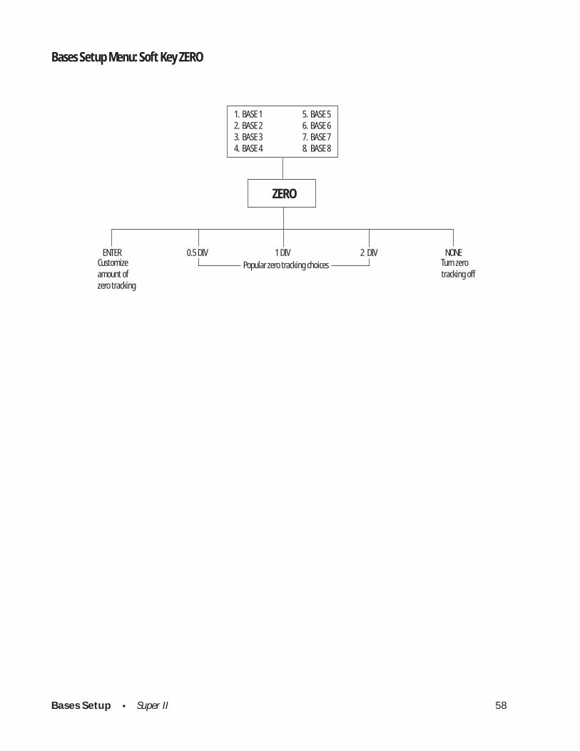
ZEROSetting the Level of Zero Tracking
The scale is programmed with a level of zero tracking designed to help the scale maintain zero weight in anormal operating setting. Zero tracking works by rejecting very small changes in weight as “noise” andkeeping the display on zero. For certain applications, such as monitoring slow flow rates, zero tracking canbe turned off. On the other hand, in “bad” or “noisy” environments, zero tracking can be increased to helpthe scale maintain zero weight when nothing is added to it.
To access the ZERO setting in the Bases Setup menu, follow the menu tree or press the keys in the order listedbelow:
To enter a level of zero tracking, use the numeric keypad followed by the ENTER soft key or choose fromthe available options. A scale division is the smallest increment that the display is set to detect. The factorydefault is set for 1/2 division of zero tracking.
Note: A zero tracking window cannot be entered at greater than 100 displayed divisions.
Display noise

Bases Setup • Super II 60
Bases Setup Menu: Soft Key RESOLUT
USER DEFAULT GO BACK
RESOLUT
1. BASE 1 5. BASE 52. BASE 2 6. BASE 63. BASE 3 7. BASE 74. BASE 4 8. BASE 8
Bases Setup • Super II 61
SETUPS MOREBASESSETUP RESOLUT
abc reset
tare
menu remote
Soft Key:
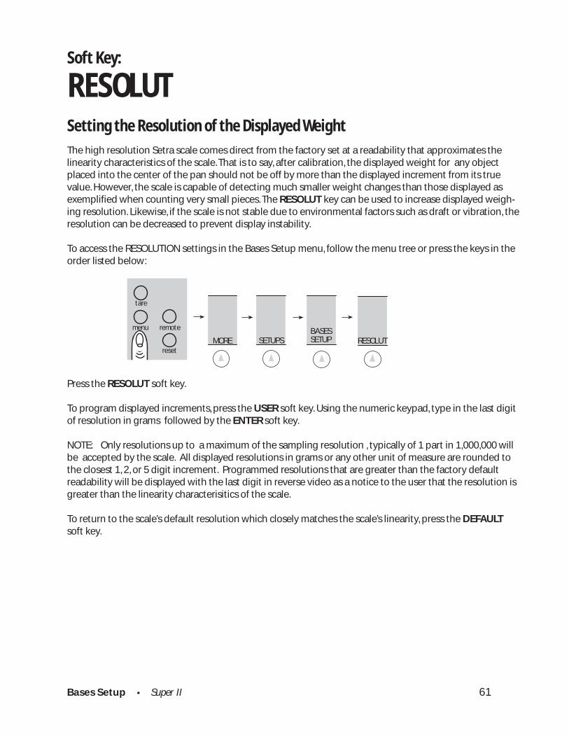
RESOLUTSetting the Resolution of the Displayed Weight
The high resolution Setra scale comes direct from the factory set at a readability that approximates thelinearity characteristics of the scale. That is to say, after calibration, the displayed weight for any objectplaced into the center of the pan should not be off by more than the displayed increment from its truevalue. However, the scale is capable of detecting much smaller weight changes than those displayed asexemplified when counting very small pieces. The RESOLUT key can be used to increase displayed weigh-ing resolution. Likewise, if the scale is not stable due to environmental factors such as draft or vibration, theresolution can be decreased to prevent display instability.
To access the RESOLUTION settings in the Bases Setup menu, follow the menu tree or press the keys in theorder listed below:
Press the RESOLUT soft key.
To program displayed increments, press the USER soft key. Using the numeric keypad, type in the last digitof resolution in grams followed by the ENTER soft key.
NOTE: Only resolutions up to a maximum of the sampling resolution , typically of 1 part in 1,000,000 willbe accepted by the scale. All displayed resolutions in grams or any other unit of measure are rounded tothe closest 1, 2, or 5 digit increment. Programmed resolutions that are greater than the factory defaultreadability will be displayed with the last digit in reverse video as a notice to the user that the resolution isgreater than the linearity characterisitics of the scale.
To return to the scale’s default resolution which closely matches the scale’s linearity, press the DEFAULTsoft key.

Bases Setup • Super II 62
Bases Setup Menu: Soft Key INFO
INFO
1. BASE 1 5. BASE 52. BASE 2 6. BASE 63. BASE 3 7. BASE 74. BASE 4 8. BASE 8
Bases Setup • Super II 63
SETUPS MOREBASESSETUP MORE
abc reset
tare
menu remote
INFO
Soft Key:
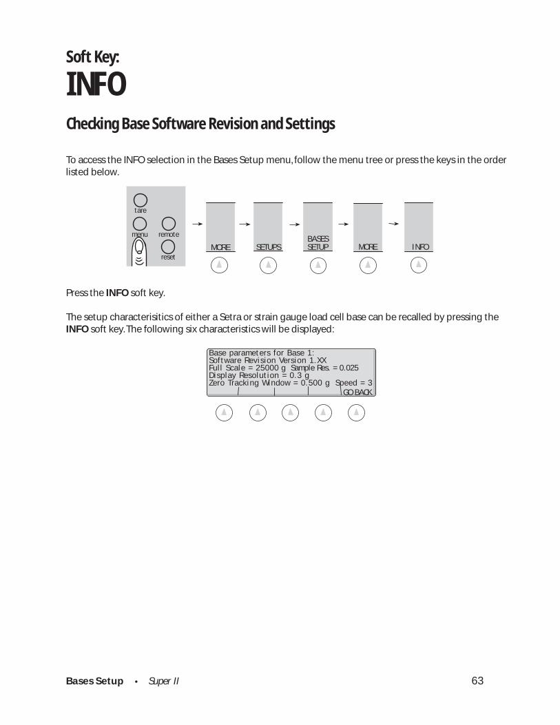
INFOChecking Base Software Revision and Settings
To access the INFO selection in the Bases Setup menu, follow the menu tree or press the keys in the orderlisted below.
Press the INFO soft key.
The setup characterisitics of either a Setra or strain gauge load cell base can be recalled by pressing theINFO soft key. The following six characteristics will be displayed:
GO BACK
Base parameters for Base 1:Software Revision Version 1.XXFull Scale = 25000 g Sample Res. = 0.025Display Resolution = 0.3 gZero Tracking Window = 0.500 g Speed = 3

Bases Setup • Super II 64
Bases Menu: Soft Key NAME
ENTER GO BACK
NAME
1. BASE 1 5. BASE 52. BASE 2 6. BASE 63. BASE 3 7. BASE 74. BASE 4 8. BASE 8
Bases Setup • Super II 65
SETUPS MOREBASESSETUP MORE
abc reset
tare
menu remote
NAME
ENTER GO BACK
Enter the Base Name (6 char max)
Soft Key:
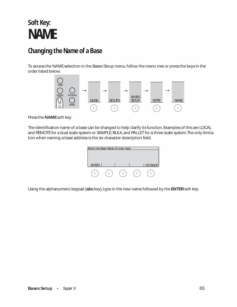
NAMEChanging the Name of a Base
To access the NAME selection in the Bases Setup menu, follow the menu tree or press the keys in theorder listed below.
Press the NAME soft key.
The identification name of a base can be changed to help clarify its function. Examples of this are LOCALand REMOTE for a dual scale system or SAMPLE, BULK, and PALLET for a three scale system.The only limita-tion when naming a base address is the six character description field.
Using the alphanumeric keypad (abc key), type in the new name followed by the ENTER soft key.
Bases Setup • Super II 66
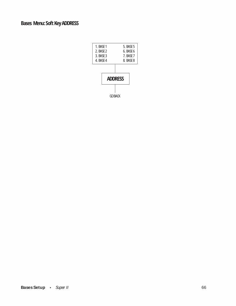
Bases Menu: Soft Key ADDRESS
ADDRESS
GO BACK
1. BASE 1 5. BASE 52. BASE 2 6. BASE 63. BASE 3 7. BASE 74. BASE 4 8. BASE 8
Bases Setup • Super II 67
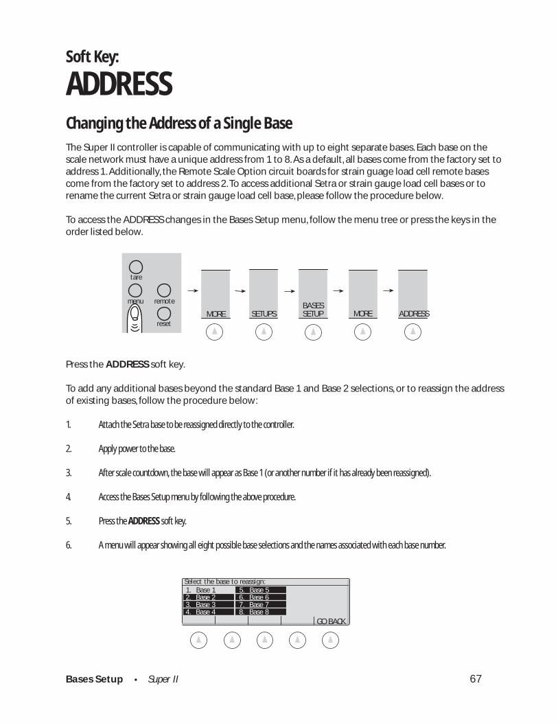
Soft Key:
ADDRESSChanging the Address of a Single BaseThe Super II controller is capable of communicating with up to eight separate bases. Each base on thescale network must have a unique address from 1 to 8. As a default, all bases come from the factory set toaddress 1. Additionally, the Remote Scale Option circuit boards for strain guage load cell remote basescome from the factory set to address 2. To access additional Setra or strain gauge load cell bases or torename the current Setra or strain gauge load cell base, please follow the procedure below.
To access the ADDRESS changes in the Bases Setup menu, follow the menu tree or press the keys in theorder listed below.
Press the ADDRESS soft key.
To add any additional bases beyond the standard Base 1 and Base 2 selections, or to reassign the addressof existing bases, follow the procedure below:
1. Attach the Setra base to be reassigned directly to the controller.
2. Apply power to the base.
3. After scale countdown, the base will appear as Base 1 (or another number if it has already been reassigned).
4. Access the Bases Setup menu by following the above procedure.
5. Press the ADDRESS soft key.
6. A menu will appear showing all eight possible base selections and the names associated with each base number.
SETUPS MOREBASESSETUP MORE
abc reset
tare
menu remote
ADDRESS
GO BACK
Select the base to reassign: 1. Base 1 5. Base 5 2. Base 2 6. Base 6 3. Base 3 7. Base 7 4. Base 4 8. Base 8

Bases Setup • Super II 68
7. Using the numeric keypad, select the base address to reassign.
8. Using the numeric keypad, select the new address for the base.
9. Unplug the base with the new address changes and plug it into the base which will be connected to the controller (Base 1).
NOTE: Once a network is setup with not more than one base per address, you can switch base addresseswithout powering down the system.
Bases Setup • Super II 69
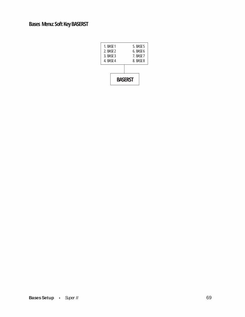
Bases Menu: Soft Key BASERST
BASERST
1. BASE 1 5. BASE 52. BASE 2 6. BASE 63. BASE 3 7. BASE 74. BASE 4 8. BASE 8
Bases Setup • Super II 70
SETUPS MOREBASESSETUP MORE
abc reset
tare
menu remote
BASERST
Soft Key:
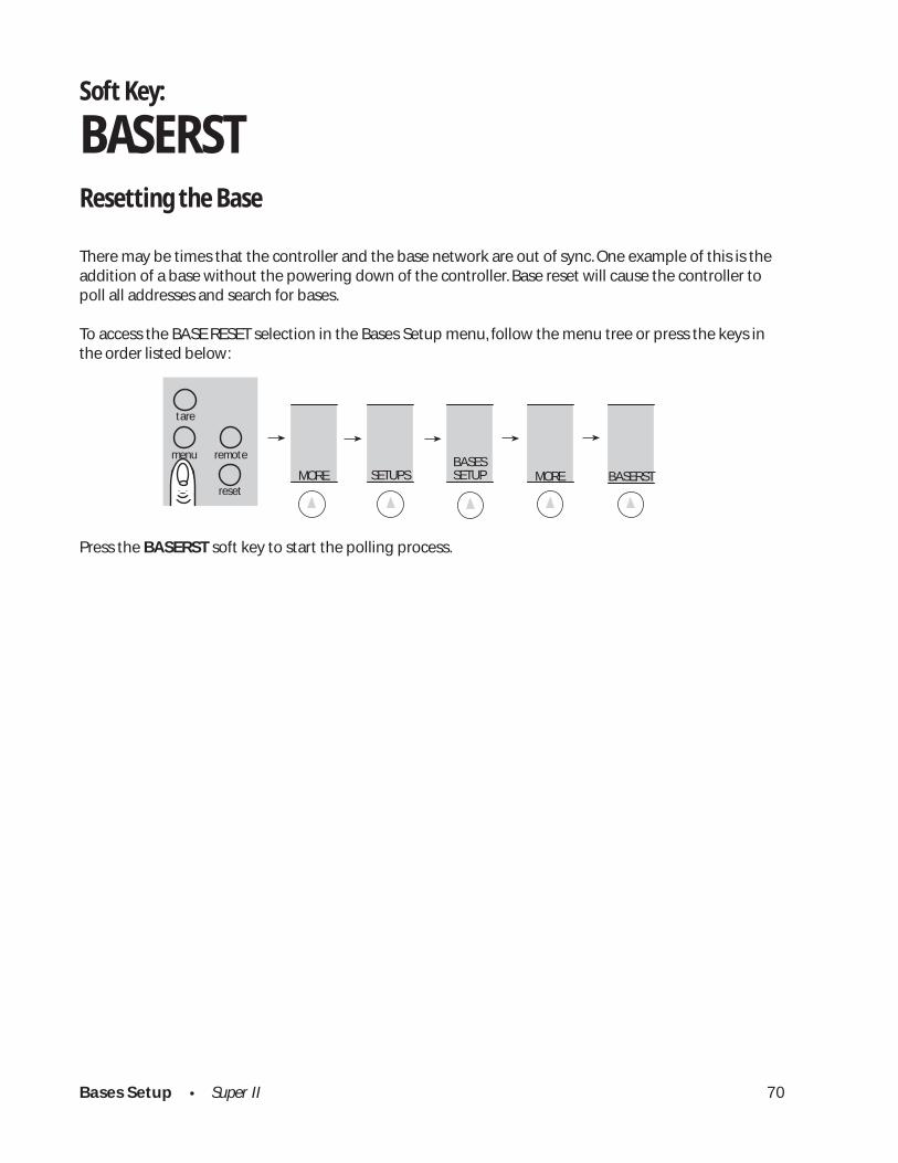
BASERSTResetting the Base
There may be times that the controller and the base network are out of sync. One example of this is theaddition of a base without the powering down of the controller. Base reset will cause the controller topoll all addresses and search for bases.
To access the BASE RESET selection in the Bases Setup menu, follow the menu tree or press the keys inthe order listed below:
Press the BASERST soft key to start the polling process.

Technical Setup • Super II 71
Technical Setup

Technical Setup • Super II 72
Technical Setup Menu: Soft Key GREETNG
LINE 1 LINE 2 LINE 3 LINE 4 GO BACK
GREETING
Type in information for each line up to 23 characters
Technical Setup • Super II 73
LINE 1 LINE 2 LINE 3 LINE 4 GO BACK
Type Greeting and select line to enter:
SETUPS TECH SETUP MORE GREETNG
abc reset
tare
menu remote
Soft Key:
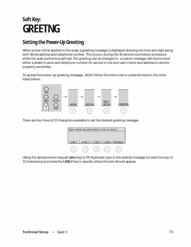
GREETNGSetting the Power-Up Greeting
When power is first applied to the scale, a greeting message is displayed showing the time and date alongwith Setra’s address and telephone number. This occurs during the 30 second countdown procedurewhile the scale performs a self-test. The greeting can be changed to a custom message. We recommendeither a dealer’s name and telephone number for service or the end user’s name and address to denoteproperty ownership.
To access the power-up greeting message, either follow the menu tree or press the keys in the orderlisted below:
There are four lines of 23 characters available to set the desired greeting message.
Using the alphanumeric keypad (abc key) or PC keyboard, type in the desired message for each line (up to23 characters) and press the LINE # key to specify where the text should appear.

Technical Setup • Super II 74
Technical Setup Menu: Soft Key BACKLIT
BAT LIM DELAY ON INPT GO BACK
BACKLIT
Enter maximum backlight Enter backlight shut-off Select whether backlightbrightness under battery delay after last input turns on with input onpower BI port or digital inputs

Technical Setup • Super II 75
SETUPS TECH SETUP MORE BACKLIT
abc reset
tare
menu remote
Enter maximum backlight brightnessunder battery power (0 - 10):
Battery brightness limit: 6
ENTER GO BACK
Select backlight battery powermanagement value to set:Battery brightness limit: 6Shut-off delay time: 1.0 min.On with B1 port or Dig. input: NO BAT LIM DELAY ON INPT GO BACK
Soft Key:
BACKLIT*
Backlighting of the Display
Adjustment of the backlight brightness can be done at any time from the front panel keys. Pressing andholding the abc key and then pressing the left arrow key will decrease the brightness of the display.Pressing and holding the abc key and then pressing the right arrow key will increase the brightness of thedisplay.
The controller can detect whether the scale is running off a (12 volt) battery or a (16 volt) AC adapter. Thescale can be set up to reduce the backlight brightness when running on batteries to save battery life. Inaddition, the backlight will shut off when powered by batteries if the scale is not in use. Both of thesebattery saving features are configurable.
To access backlighting battery power saving features, either follow the menu tree or press the keys in theorder listed below:
After pressing the BACKLIT soft key in the Technical Setups menu , the following screen will appear:
If the BAT LIM soft key is pressed, the following display appears:
Brightness can be set to a whole number value between 0 (backlight off under battery power) to 10 (fullbacklight brightness available under battery power). The factory default setting for the battery limit is 6.* For scales with the backlight option.
Technical Setup • Super II 76
Select backlight battery powermanagement value to set:Battery brightness limit: 6Shut-off delay time: 1.0 min.On with BI port or Dig. input: NO BAT LIM DELAY ON INPT GO BACK
Select backlight battery powermanagement value to set:Battery brightness limit: 6Shut-off delay time: 1.0 min.On with BI port or Dig. input: NO BAT LIM DELAY ON INPT GO BACK
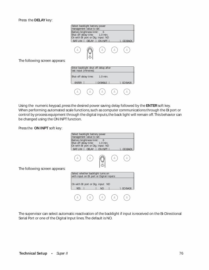
Press the DELAY key:
The following screen appears:
Using the numeric keypad, press the desired power saving delay followed by the ENTER soft key.When performing automated scale functions, such as computer communications through the BI port orcontrol by process equipment through the digital inputs, the back light will remain off. This behavior canbe changed using the ON INPT function.
Press the ON INPT soft key:
The following screen appears:
The supervisor can select automatic reactivation of the backlight if input is received on the Bi-DirectionalSerial Port or one of the Digital Input lines. The default is NO.
Enter backlight shut-off delay afterlast input (minutes):
Shut-off delay time: 1.0 min.
ENTER DISABLE GO BACK
Select whether backlight turns onwith input on BI port or Digital Inputs:
On with BI port or Dig. input: NO
YES NO GO BACK
Technical Setup • Super II 77
DATBASE TRANSAC GO BACKRECORDS RECORDS
Technical Setup Menu: Soft Key SETUP TRANSFR
SETUPTRANSFER
Sends database records Sends transaction log records
CONTROLLER ALL RECORDS MORE GO BACK SETUPS SETUPS
Sends all controller Sends all controller setupssetups including macros and base setupsand print setups
BASIC MACRO PRINT BASES GO BACK SETUPS SETUPS SETUPS SETUPS
Sends controller setups Sends each programmed Sends each programmed Sends the base setupexcept prompting prompting macro print key setup ; Eltron, DYMO information exceptmacros and print setups including step sequence ScriptCoder setups saved in current zero, current span
and prompts their own formats and linearity data.

Technical Setup • Super II 78
Select the setups to transfer:
BASIC MACRO PRINT BASES GO BACK SETUPS SETUPS SETUPS SETUPS
CONTRLLR ALL RECORDS MORE GO BACK SETUPS SETUPS
Select setups to upload:
CONTRLLR ALL RECORDS MORE GO BACK SETUPS SETUPS
Select setups to upload:
SETUPS TECH SETUP MORE
SETUPTRANSFR
abc reset
tare
menu remote
Soft Key:
SETUP TRANSFR*
Transferring the Scale Setups to a Scale or Computer
The controller uses an interface language called the Setra Dialog Language (SDL). Using SDL, the setupinformation can be transferred to another scale or to a computer file in order to back up the scale setups.Through the SETUP TRANSFR menu, the entire scale setup, or a portion of the setups, can be sent out the BIport.
To access the SETUP TRANSFR menu, follow the menu tree or press the keys in the order listed below:
The following screen and soft keys appear:
Pressing the MORE soft key will display the following additional choices:
Press the RECORDS soft key:
* Available in Software Revisions 3.01 and higher.

Technical Setup • Super II 79
DATABASE TRANSAC GO BACK RECORDS RECORDS
Select the setups to transfer:
The following additional choices will be displayed:
Press one of the transfer options shown on the previous page to transfer some portion of the setups:
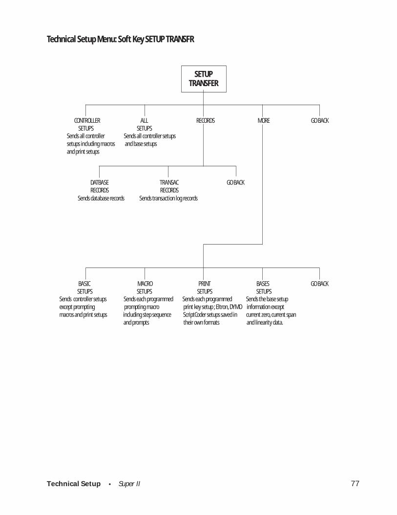
CNTRLLR SETUPS Sends all the controller data including the prompting macros, print setups, andcontroller setups (see below). Does not transfer the bases setup, transaction logrecords or the database records.
ALL SETUPS Sends all the above CNTRLLR setups as well as the base setups.
BASIC SETUPS Sends the Controller setups described in this manual except the prompting macrosand the print setups.
MACRO SETUPS Sends each prompting macro that has been programmed. Eltron, DYMO, andScriptCoder setups are saved in their own format.
BASE SETUPS Sends the base setup information. The following items are not base setup informa-tion and cannot be read from the base: the current zero, the current span, and thelinearity data.
DATBASE RECORDS Sends the database records.
TRANSAC RECORDS Sends the transaction log records.
Technical Setup • Super II 80
FACDEF CLEAR CLEAR CLEAR GO BACKDB PRINT MACRO
Technical Setup Menu: Soft Key RESET
RESET
Restores all factory settings and performance characteristics
Clears all print formats
Clears all programmed macros
YES NO YES NO
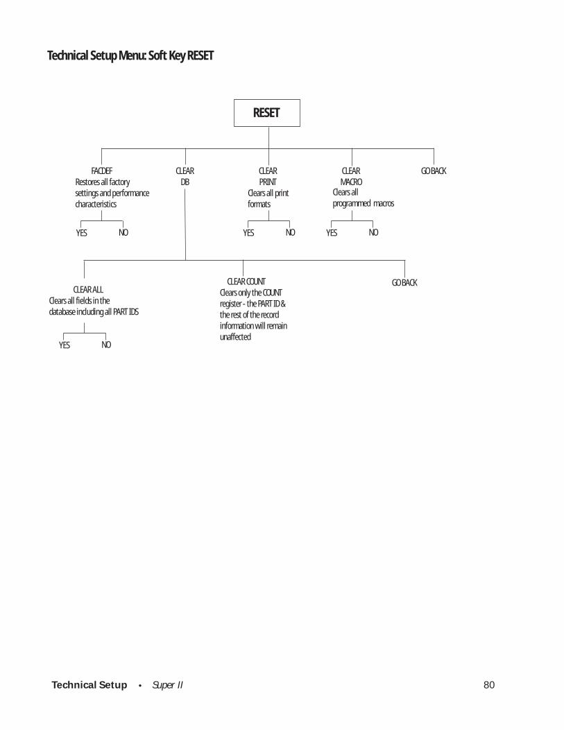
CLEAR ALL Clears all fields in the database including all PART IDS
CLEAR COUNTClears only the COUNTregister - the PART ID &the rest of the recordinformation will remainunaffected
GO BACK
YES NO
YES NO
Technical Setup • Super II 81
FACDEF CLEAR CLEAR CLEAR GO BACK DB PRINT MACRO
Select from the Reset Options below:
SETUPS TECH SETUP MORE
abc reset
tare
menu remote
RESET
FACDEF CLEAR CLEAR CLEAR GO BACK DB PRINT MACRO
Select from the Reset Options below:
Soft Key:
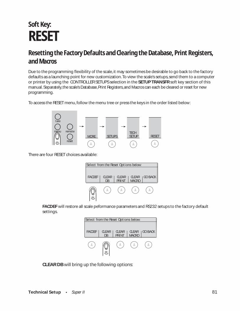
RESETResetting the Factory Defaults and Clearing the Database, Print Registers,and Macros
Due to the programming flexibility of the scale, it may sometimes be desirable to go back to the factorydefaults as a launching point for new customization. To view the scale’s setups, send them to a computeror printer by using the CONTROLLER SETUPS selection in the SETUP TRANSFR soft key section of thismanual. Separately, the scale’s Database, Print Registers, and Macros can each be cleared or reset for newprogramming.
To access the RESET menu, follow the menu tree or press the keys in the order listed below:
There are four RESET choices available:
FACDEF will restore all scale peformance parameters and RS232 setups to the factory defaultsettings.
CLEAR DB will bring up the following options:
Technical Setup • Super II 82
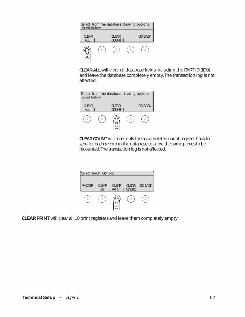
CLEAR CLEAR GO BACK ALL COUNT
Select from the database clearing optionslisted below:
CLEAR CLEAR GO BACK ALL COUNT
Select from the database clearing optionslisted below:
FACDEF CLEAR CLEAR CLEAR GO BACK DB PRINT MACRO
Select Reset Option:
CLEAR ALL will clear all database fields including the PART ID (ID0)and leave the database completely empty. The transaction log is notaffected.
CLEAR COUNT will reset only the accumulated count register back tozero for each record in the database to allow the same pieces to berecounted. The transaction log is not affected.
CLEAR PRINT will clear all 10 print registers and leave them completely empty.
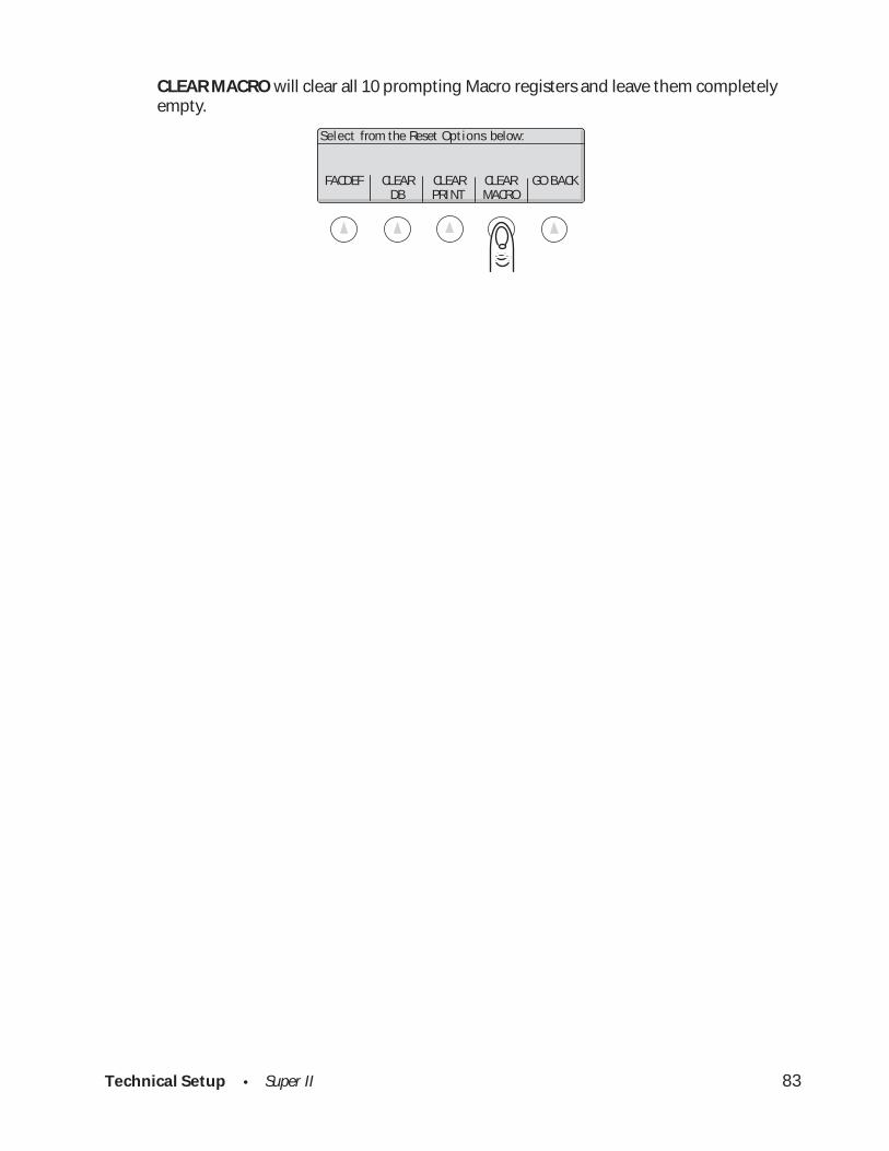
Technical Setup • Super II 83
CLEAR MACRO will clear all 10 prompting Macro registers and leave them completelyempty.
FACDEF CLEAR CLEAR CLEAR GO BACK DB PRINT MACRO
Select from the Reset Options below:
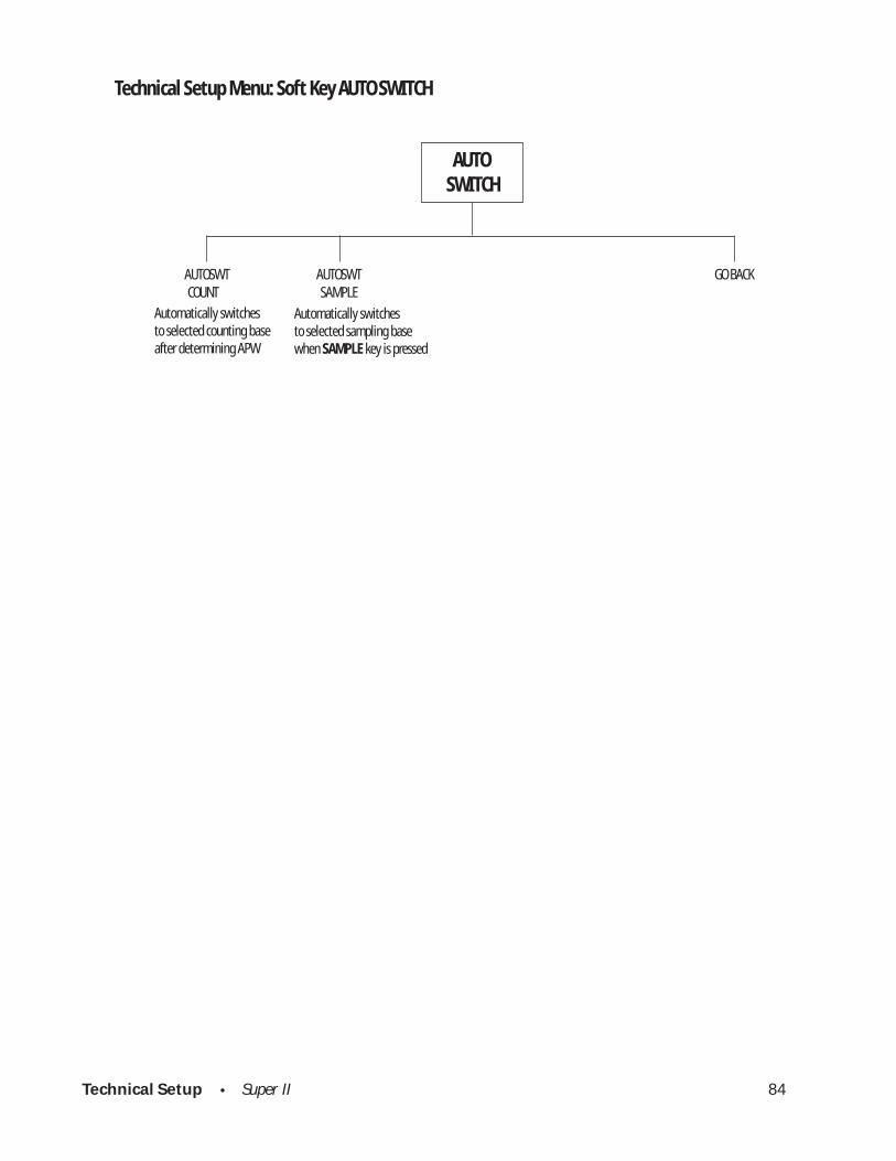
Technical Setup • Super II 84
Technical Setup Menu: Soft Key AUTO SWITCH
AUTOSWITCH
COUNT SAMPLEAUTOSWT AUTOSWT GO BACK
Automatically switchesto selected counting baseafter determining APW
Automatically switchesto selected sampling basewhen SAMPLE key is pressed
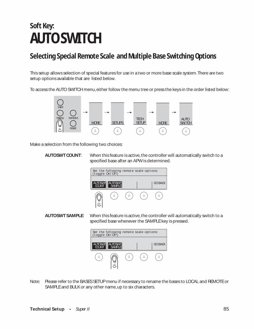
Technical Setup • Super II 85
SETUPS MORE TECH SETUP MORE
abc reset
tare
menu remote AUTOSWITCH
Set the fol lowing remote scale options:(toggle On/Off)
AUTOSWT AUTOSWT GO BACK COUNT SAMPLE
Set the fol lowing remote scale options:(toggle On/Off)
AUTOSWT AUTOSWT GO BACK COUNT SAMPLE
Soft Key:
AUTO SWITCHSelecting Special Remote Scale and Multiple Base Switching Options
This setup allows selection of special features for use in a two or more base scale system. There are twosetup options available that are listed below.
To access the AUTO SWITCH menu, either follow the menu tree or press the keys in the order listed below:
Make a selection from the following two choices:
AUTOSWT COUNT: When this feature is active, the controller will automatically switch to aspecified base after an APW is determined.
AUTOSWT SAMPLE: When this feature is active, the controller will automatically switch to aspecified base whenever the SAMPLE key is pressed.
Note: Please refer to the BASES SETUP menu if necessary to rename the bases to LOCAL and REMOTE orSAMPLE and BULK or any other name, up to six characters.

Technical Setup • Super II 86
Technical Setup Menu: Soft Key ALARMS
ALARMS
ENABLE DISABLE PROGRAM GO BACK
ALARM 1 ALARM 2 ALARM 3 GO BACK
LEVEL LATCH GO BACK
REGION1 REGION2 REGION3 REGION4 GO BACK

Technical Setup • Super II 87
Soft Key:
ALARMSSetting Up the Alarm Outputs
The controller has three digital alarm outputs that can be used to control an external system. The alarmoutput pins are located in the OUT port. The state of the alarm is based on the weight of the scale relativeto the set points (see the SETPOINTS soft key in the USER’S MANUAL). The alarm pins are held at eitherØ volts (LO) or 5 volts (HI).
There are three set points that the operator can program: Low, Target and High. The set points can beprogrammed to any weight as long as the Low set point is lower than the Target set point and that, in turn,is lower than the High set point. The three set points create four weight regions. Region 1 covers allweights lower than the Low set point. Region 2 is between the Low and Target set points. Region 3 isbetween the Target and the High set points. Region 4 covers all weights greater than the High set point.Each alarm can be programmed to be either LO or HI in each of the four regions.
The alarm can be configured to be either latching or non-latching. When in the latching mode, once analarm output has changed state, it will remain in the new state until a reset signal is received (the resetsignal can be sent through the digital inputs, the keypad, or an SDL command).
When the alarms are programmed, the user menu selection SETPOINT changes to ALARMS. The functional-ity of the SETPOINT remains in the menu selection, but extra controls are added for operating the alarms.See the “User Manual” for further details.
To access the ALARMS menu, follow the menu tree or press the keys in the order listed below:
Choose from the options below:
SETUPS MORE TECH SETUP MORE ALARMS
abc reset
tare
menu remote
Alarm Outputs:LOW TARGET HIGH LATCH
ALARM 1 LO HI HI HIALARM 2 LO LO HI HIALARM 3 LO LO LO HI
ENABLE DISABLE PROGRAM GO BACK

Technical Setup • Super II 88
LOW TARGET HIGH LATCHALARM 1 LO HI HI HIALARM 2 LO LO HI HIALARM 3 LO LO LO HI
Select Alarm to program:
ALARM1 ALARM2 ALARM3 GO BACK
LOW TARGET HIGH LATCHALARM 1 LO HI HI HIALARM 2 LO LO HI HIALARM 3 LO LO LO HI
Alarms Outputs:
ENABLE DISABLE PROGRAM GO BACK
Select program of LEVELs or toggle LATCH:LOW TARGET HIGH LATCH
ALARM 1 LO LO HI HI
LEVEL LATCH GO BACK
Select programming Alarm LEVEL or LATCH:LOW TARGET HIGH LATCH
ALARM 2 LO LO HI HI
LEVEL LATCH GO BACK
When the alarms are disabled, all the outputs are set to their zero weight states. When the alarms areenabled they follow the chart shown on the ALARM OUTPUTS screen where LO indicates that the alarmpin will be 0 volts relative to ground and HI indicates 5 volts. Thus, on the display shown below, when theweight is between the TARGET and HIGH set points the output of ALARM1 is HI, ALARM 2 is HI, and ALARM3 is LO. Use the soft keys to enable and disable the alarms. Press the PROGRAM soft key to program thechart.
When the program key is pressed,
the following soft keys are shown:
Select ALARM1, ALARM2, or ALARM3 to program a particular alarm. When you select an alarm, thefollowing display appears:
If the LATCH soft key is pressed, a “lock” is displayed in the LATCH column, causing the alarm to be latching(see above description). If no symbol is present in the LATCH column, the alarm is non-latching.

Technical Setup • Super II 89
Press the LEVEL soft key to set the behavior of the alarm in a particular region. The following screen andsoft key is displayed:
Pressing one of the keys marked REGION will toggle the behavior of the alarm from LO to HI or vice-versafor the region selected.
Press a Region Key to invert a region:LOW TARGET HIGH LATCH
REGION1 REGION2 REGION3 REGION4ALARM 2 LO LO HI HI
REGION1 REGION2 REGION3 REGION4 GO BACK

Technical Setup • Super II 90
Technical Setup Menu: Soft Key DIG INP
DIG INP
INPUT 1 INPUT 2 GO BACK
NONE GO BACK
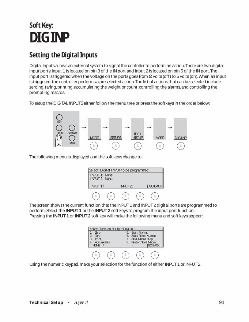
Technical Setup • Super II 91
SETUPS TECH SETUP MORE MORE
abc reset
tare
menu remote
DIG INP
Soft Key:
DIG INPSetting the Digital Inputs
Digital Inputs allows an external system to signal the contoller to perform an action. There are two digitalinput ports: Input 1 is located on pin 3 of the IN port and Input 2 is located on pin 5 of the IN port. Theinput port is triggered when the voltage on the ports goes from Ø volts (off ) to 5 volts (on). When an inputis triggered, the controller performs a preselected action. The list of actions that can be selected includezeroing, taring, printing, accumulating the weight or count, controlling the alarms, and controlling theprompting macros.
To setup the DIGITAL INPUTS either follow the menu tree or press the softkeys in the order below:
The following menu is displayed and the soft keys change to:
The screen shows the current function that the INPUT 1 and INPUT 2 digital ports are programmed toperform. Select the INPUT 1 or the INPUT 2 soft keys to program the input port function.Pressing the INPUT 1 or INPUT 2 soft key will make the following menu and soft keys appear:
Using the numeric keypad, make your selection for the function of either INPUT 1 or INPUT 2.
NONE GO BACK
Select function of Digital INPUT 1:1. Zero 5. Start Alarms2. Tare 6. Stop/Reset Alarms3. Print 7. Next Macro Step4. Accumulate 8. Restart/Exit Macro
INPUT 1 INPUT 2 GO BACK
Select Digital INPUT to be programmed:INPUT 1: NoneINPUT 2: None
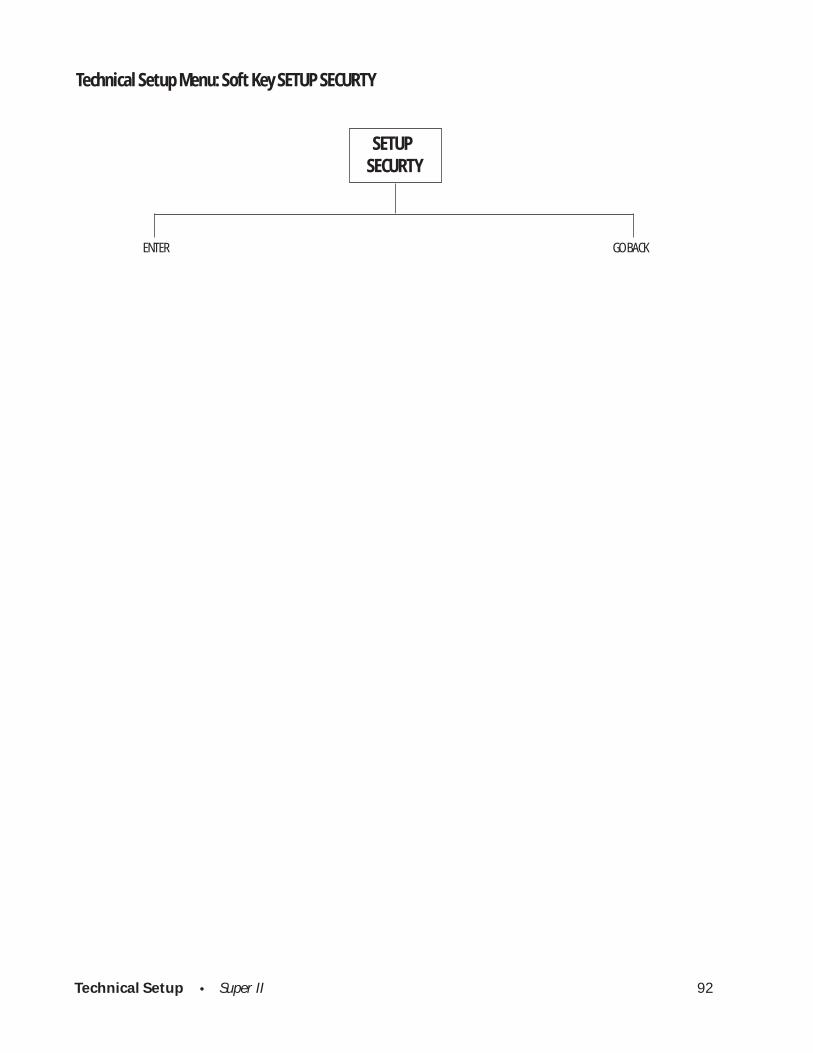
Technical Setup • Super II 92
Technical Setup Menu: Soft Key SETUP SECURTY
SETUPSECURTY
ENTER GO BACK
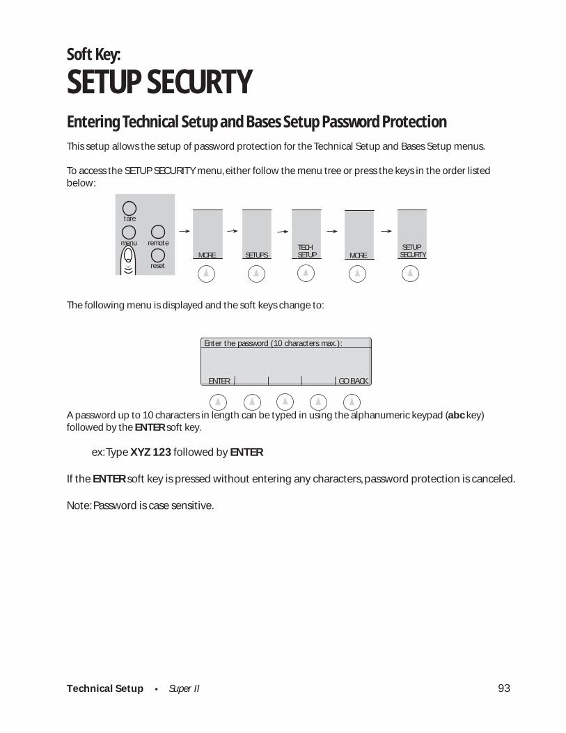
Technical Setup • Super II 93
Soft Key:
SETUP SECURTYEntering Technical Setup and Bases Setup Password ProtectionThis setup allows the setup of password protection for the Technical Setup and Bases Setup menus.
To access the SETUP SECURITY menu, either follow the menu tree or press the keys in the order listedbelow:
The following menu is displayed and the soft keys change to:
A password up to 10 characters in length can be typed in using the alphanumeric keypad (abc key)followed by the ENTER soft key.
ex: Type XYZ 123 followed by ENTER
If the ENTER soft key is pressed without entering any characters, password protection is canceled.
Note: Password is case sensitive.
SETUPS MORETECHSETUP
abc reset
tare
menu remote
MORE SETUPSECURTY
ENTER GO BACK
Enter the password (10 characters max.):
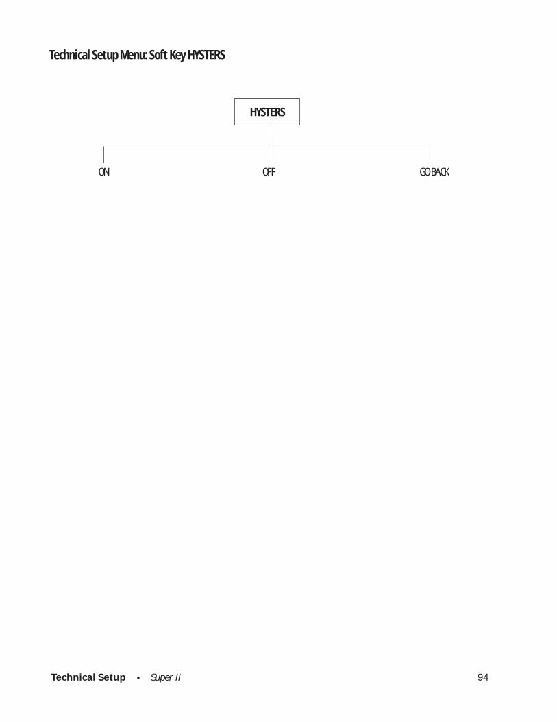
Technical Setup • Super II 94
Technical Setup Menu: Soft Key HYSTERS
HYSTERS
ON OFF GO BACK
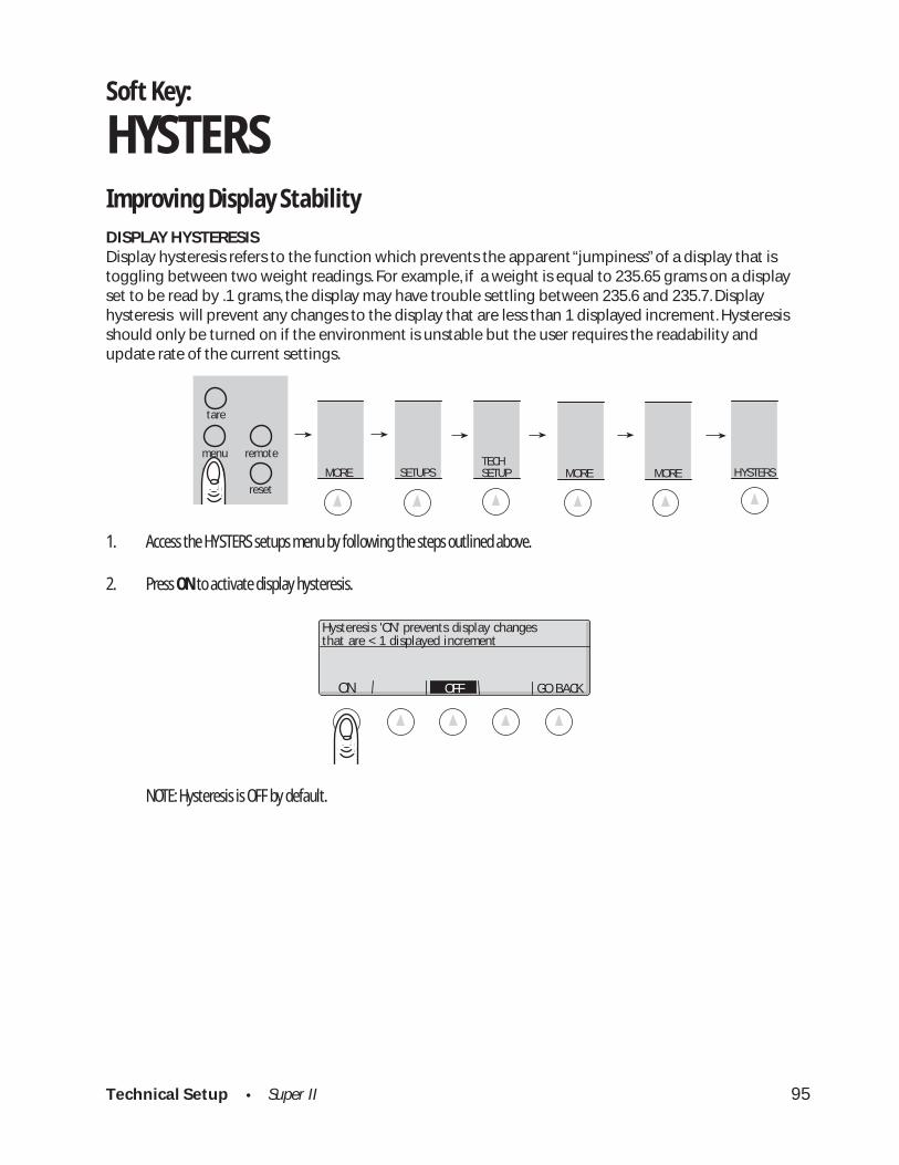
Technical Setup • Super II 95
SETUPS MORETECHSETUP
abc reset
tare
menu remote
HYSTERS MORE MORE
Hysteresis 'ON' prevents display changesthat are < 1 displayed increment
ON OFF GO BACK
Soft Key:
HYSTERSImproving Display Stability
DISPLAY HYSTERESISDisplay hysteresis refers to the function which prevents the apparent “jumpiness” of a display that istoggling between two weight readings. For example, if a weight is equal to 235.65 grams on a displayset to be read by .1 grams, the display may have trouble settling between 235.6 and 235.7. Displayhysteresis will prevent any changes to the display that are less than 1 displayed increment. Hysteresisshould only be turned on if the environment is unstable but the user requires the readability andupdate rate of the current settings.
1. Access the HYSTERS setups menu by following the steps outlined above.
2. Press ON to activate display hysteresis.
NOTE: Hysteresis is OFF by default.
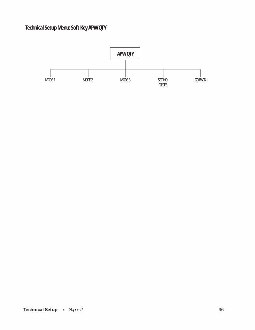
Technical Setup • Super II 96
Technical Setup Menu: Soft Key APW QTY
MODE 1 MODE 2 MODE 3 SET NO. GO BACKPIECES
APW QTY
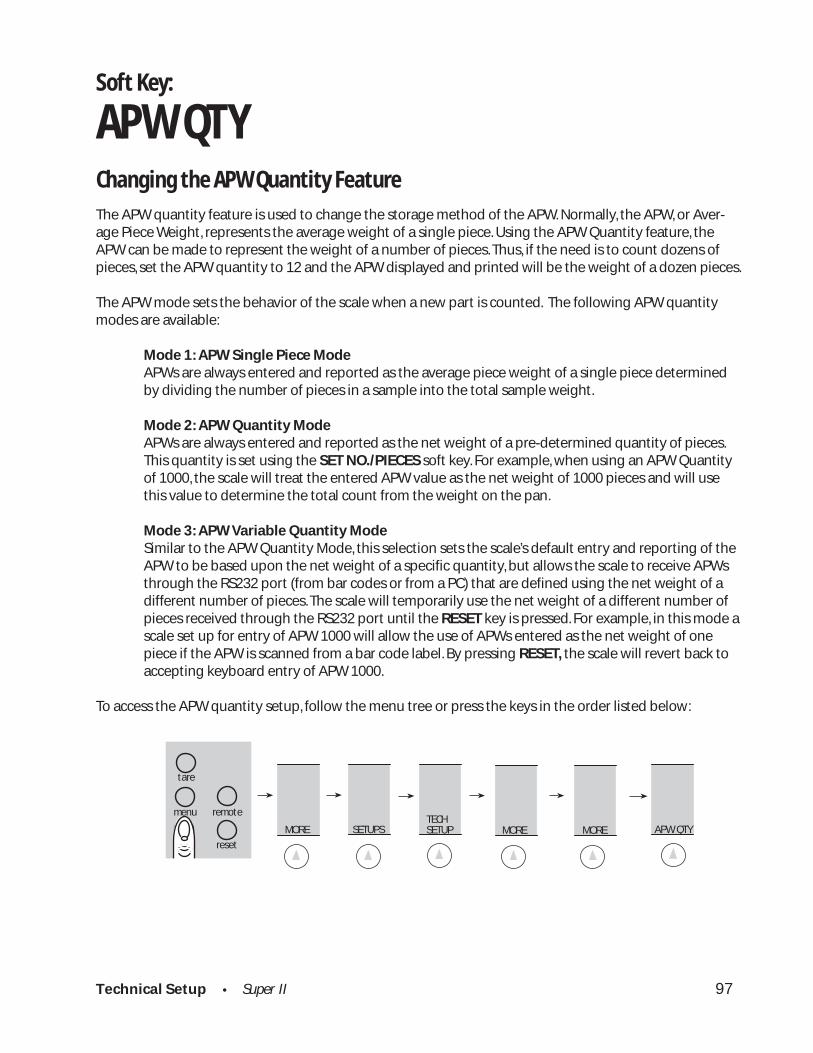
Technical Setup • Super II 97
Soft Key:
APW QTYChanging the APW Quantity Feature
The APW quantity feature is used to change the storage method of the APW. Normally, the APW, or Aver-age Piece Weight, represents the average weight of a single piece. Using the APW Quantity feature, theAPW can be made to represent the weight of a number of pieces. Thus, if the need is to count dozens ofpieces, set the APW quantity to 12 and the APW displayed and printed will be the weight of a dozen pieces.
The APW mode sets the behavior of the scale when a new part is counted. The following APW quantitymodes are available:
Mode 1: APW Single Piece ModeAPWs are always entered and reported as the average piece weight of a single piece determinedby dividing the number of pieces in a sample into the total sample weight.
Mode 2: APW Quantity ModeAPWs are always entered and reported as the net weight of a pre-determined quantity of pieces.This quantity is set using the SET NO./PIECES soft key. For example, when using an APW Quantityof 1000, the scale will treat the entered APW value as the net weight of 1000 pieces and will usethis value to determine the total count from the weight on the pan.
Mode 3: APW Variable Quantity ModeSimilar to the APW Quantity Mode, this selection sets the scale’s default entry and reporting of theAPW to be based upon the net weight of a specific quantity, but allows the scale to receive APWsthrough the RS232 port (from bar codes or from a PC) that are defined using the net weight of adifferent number of pieces. The scale will temporarily use the net weight of a different number ofpieces received through the RS232 port until the RESET key is pressed. For example, in this mode ascale set up for entry of APW 1000 will allow the use of APWs entered as the net weight of onepiece if the APW is scanned from a bar code label. By pressing RESET, the scale will revert back toaccepting keyboard entry of APW 1000.
To access the APW quantity setup, follow the menu tree or press the keys in the order listed below:
SETUPS MORETECHSETUP
abc reset
tare
menu remote
APW QTY MORE MORE

Technical Setup • Super II 98
The following screen and soft keys will be displayed:
Select the APW quantity mode desired using the MODE 1, MODE 2, or MODE 3 soft keys.
Press the SET NO. PIECES soft key to display the following screen and soft keys: Either select a predefinedAPW quantity from the soft keys or enter a custom APW quantity using the numeric keypad and pressenter.
Select default pieces for APW quantity mode, orenter pieces and press ENTER:
ENTER APW 1 APW 12 APW 100 APW 1000APW PIECES: 1000
MODE 1 MODE 2 MODE 3 SET NO. GO BACK PIECES
Select APW Quantity mode or set pieces:1) APW Single Piece Mode2) APW Quantity Mode3) APW Variable Quantity Mode

Appendix A • Super II 99
Appendix A
RS232 Serial Port Communications
The Super II comes equipped with three RS232 ports. They are labelled BI, for a “bi-directional” port for PCor computer communications, OUT for an “output” port for a printer, and IN for an “input” port for a barcode scanner. Users who have purchased Setra’s peripherals such as the Dymo SETRA 300 printer or theSetra SmartWand can simply plug these devices into the appropriate port and start using them. The firstpart of this appendix describes the RS232 command and communication protocol. The second part of theappendix describes the characteristics of the ports.
Interfacing a Setra Super II Scale to a Computer
The bi-directional port interface not only allows the scale to transmit data to and from a computer, butalso enables a computer to control a scale. Since the baud rate and databits of this interface are selectable(see PORTS soft key setup in this manual), virtually any computer or terminal with an RS232 port can beconnected to the scale. Setra Super II does not support software handshaking and supports hardwarehandshaking only on the “bi-directional” port . This section describes the conventions and formats used tocommunicate with the Super II.
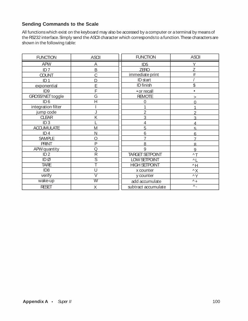
Appendix A • Super II 100
FUNCTION
APWID 7
COUNTID 1
exponentialID9
GROSS/NET toggleID 6
integration filterjump code
CLEARID 3
ACCUMULATEID 4
SAMPLEPRINT
APW quantityID 2ID ØTAREID8
verifywake-up
ASCII
ABCDEFGHIJKLMNOPQRSTUVW
Sending Commands to the Scale
All functions which exist on the keyboard may also be accessed by a computer or a terminal by means ofthe RS232 interface. Simply send the ASCII character which corresponds to a function. These characters areshown in the following table:
• or recallREMOTE
0123456789
TARGET SETPOINTLOW SETPOINTHIGH SETPOINT
x countery counter
>0123456789
^T^L^H^X^Y^+^-
FUNCTION ASCII
RESET X
ID5ZERO
immediate printID startID finish
Y
$/#Z
•
subtract accumulateadd accumulate
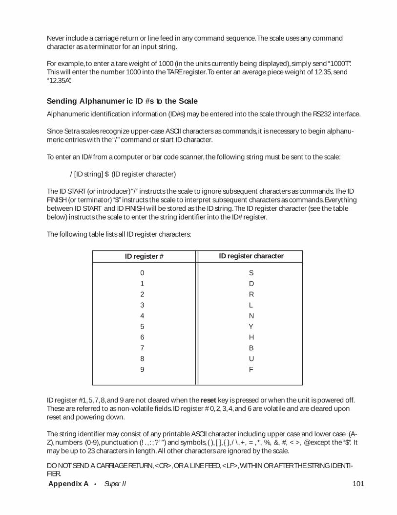
Appendix A • Super II 101
Never include a carriage return or line feed in any command sequence. The scale uses any commandcharacter as a terminator for an input string.
For example, to enter a tare weight of 1000 (in the units currently being displayed), simply send “1000T”.This will enter the number 1000 into the TARE register. To enter an average piece weight of 12.35, send“12.35A”.
Sending Alphanumer ic ID #s to the Scale
Alphanumeric identification information (ID#s) may be entered into the scale through the RS232 interface.
Since Setra scales recognize upper-case ASCII characters as commands, it is necessary to begin alphanu-meric entries with the “/” command or start ID character.
To enter an ID# from a computer or bar code scanner, the following string must be sent to the scale:
/ [ID string] $ (ID register character)
The ID START (or introducer) “/” instructs the scale to ignore subsequent characters as commands. The IDFINISH (or terminator) “$” instructs the scale to interpret subsequent characters as commands. Everythingbetween ID START and ID FINISH will be stored as the ID string. The ID register character (see the tablebelow) instructs the scale to enter the string identifier into the ID# register.
The following table lists all ID register characters:
0 S
1 D
2 R
3 L
4 N
5 Y
6 H
7 B
8 U
9 F
ID register #1, 5, 7, 8, and 9 are not cleared when the reset key is pressed or when the unit is powered off.These are referred to as non-volatile fields. ID register # 0, 2, 3, 4, and 6 are volatile and are cleared uponreset and powering down.
The string identifier may consist of any printable ASCII character including upper case and lower case (A-Z), numbers (0-9), punctuation (! . , : ; ? ’ ”) and symbols, ( ), [ ], { }, / \, +, = , *, %, &, #, < >, @ except the “$”. Itmay be up to 23 characters in length. All other characters are ignored by the scale.
DO NOT SEND A CARRIAGE RETURN, <CR>, OR A LINE FEED, <LF>, WITHIN OR AFTER THE STRING IDENTI-FIER.
ID register # ID register character
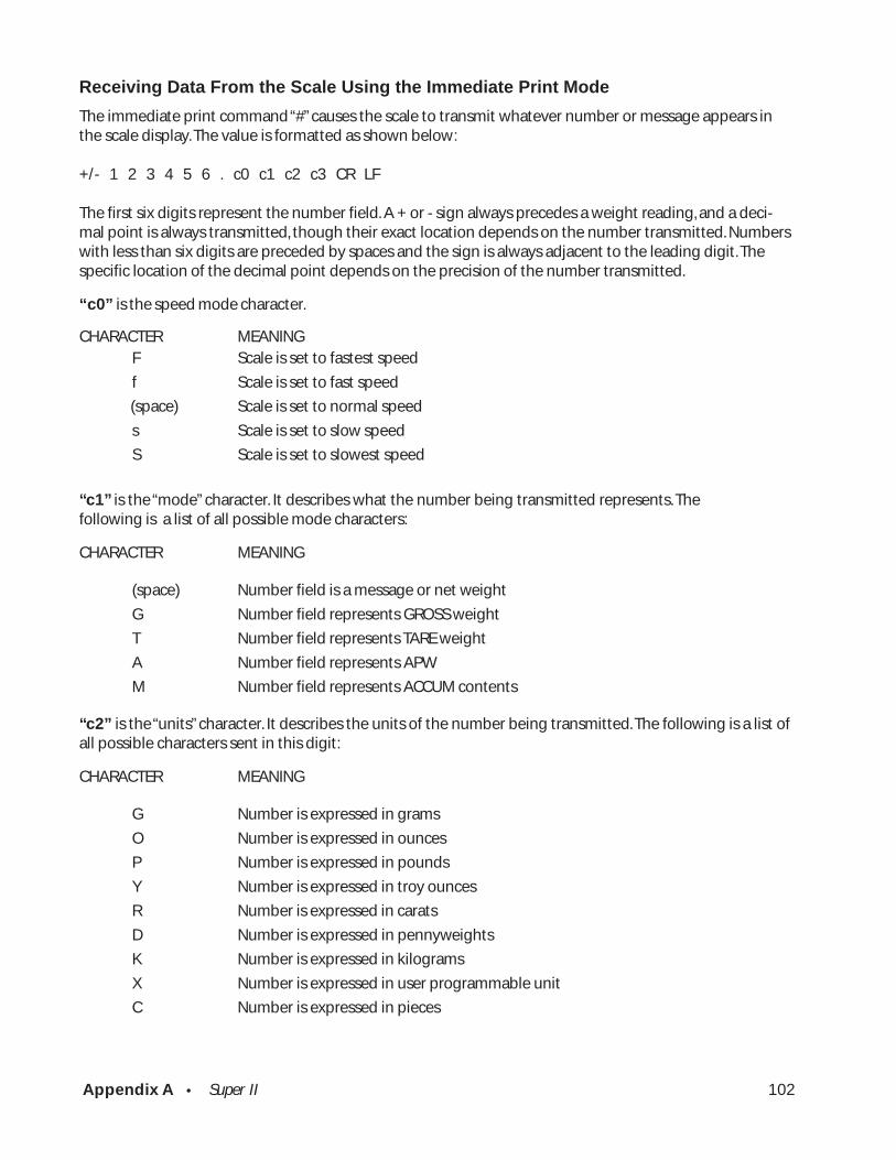
Appendix A • Super II 102
Receiving Data From the Scale Using the Immediate Print Mode
The immediate print command “#” causes the scale to transmit whatever number or message appears inthe scale display. The value is formatted as shown below:
+/- 1 2 3 4 5 6 . c0 c1 c2 c3 CR LF
The first six digits represent the number field. A + or - sign always precedes a weight reading, and a deci-mal point is always transmitted, though their exact location depends on the number transmitted. Numberswith less than six digits are preceded by spaces and the sign is always adjacent to the leading digit. Thespecific location of the decimal point depends on the precision of the number transmitted.
“c0” is the speed mode character.
CHARACTER MEANINGF Scale is set to fastest speed
f Scale is set to fast speed
(space) Scale is set to normal speed
s Scale is set to slow speed
S Scale is set to slowest speed
“c1” is the “mode” character. It describes what the number being transmitted represents. Thefollowing is a list of all possible mode characters:
CHARACTER MEANING
(space) Number field is a message or net weight
G Number field represents GROSS weight
T Number field represents TARE weight
A Number field represents APW
M Number field represents ACCUM contents
“c2” is the “units” character. It describes the units of the number being transmitted. The following is a list ofall possible characters sent in this digit:
CHARACTER MEANING
G Number is expressed in grams
O Number is expressed in ounces
P Number is expressed in pounds
Y Number is expressed in troy ounces
R Number is expressed in carats
D Number is expressed in pennyweights
K Number is expressed in kilograms
X Number is expressed in user programmable unit
C Number is expressed in pieces
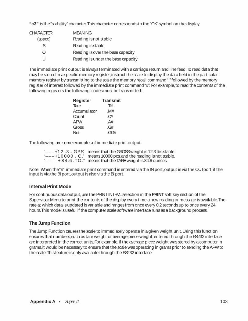
Appendix A • Super II 103
“c3” is the “stability” character. This character corresponds to the “OK” symbol on the display.
CHARACTER MEANING(space) Reading is not stable
S Reading is stable
O Reading is over the base capacity
U Reading is under the base capacity
The immediate print output is always terminated with a carriage return and line feed. To read data thatmay be stored in a specific memory register, instruct the scale to display the data held in the particularmemory register by transmitting to the scale the memory recall command “.” followed by the memoryregister of interest followed by the immediate print command “#”. For example, to read the contents of thefollowing registers, the following codes must be transmitted:
Register Tr ansmitTare .T#Accumulator .M#Count .C#APW .A#Gross .G#Net .GG#
The following are some examples of immediate print output:
“– – – +1 2 . 3 - G P S” means that the GROSS weight is 12.3 lbs stable.“– – – +1 0 0 0 0 - C -” means 10000 pcs, and the reading is not stable.“– – – – + 8 4 . 6 - T O -” means that the TARE weight is 84.6 ounces.
Note: When the “#” immediate print command is entered via the IN port, output is via the OUTport; if theinput is via the BI port, output is also via the BI port.
Interval Print Mode
For continuous data output, use the PRINT INTRVL selection in the PRINT soft key section of theSupervisor Menu to print the contents of the display every time a new reading or message is available. Therate at which data is updated is variable and ranges from once every 0.2 seconds up to once every 24hours. This mode is useful if the computer scale software interface runs as a background process.
The Jump Function
The Jump Function causes the scale to immediately operate in a given weight unit. Using this functionensures that numbers, such as tare weight or average piece weight, entered through the RS232 interfaceare interpreted in the correct units. For example, if the average piece weight was stored by a computer ingrams, it would be necessary to ensure that the scale was operating in grams prior to sending the APW tothe scale. This feature is only available through the RS232 interface.
Appendix A • Super II 104
To use the Jump Function, send an nJ to the scale, where “J” is the Jump function command and “n” is theunit code. The units code ranges from 0 to 7 as shown:
Units Code Unit0 User programmable unit (default GRAINS)1 GRAMS2 OZ (ounces)3 LBS (pounds)4 TROY (troy ounces)5 DWT (pennyweights)6 CARATS7 KG
Do not send any number other than 0-7. For example, to enter an average piece weight of 0.23456 gramsfrom a computer, send “1J0.23456A”. The “1J” sets the scale for operation in grams. The “0.23456A” tells thescale to enter that weight into the APW register. The Jump Function prevents misinterpretation of valuesentered from a computer.
The Quantity Function
The Quantity Function operates very much like the “jump function” for the APW. By sending a numericvalue followed by the letter Q, the scale will then accept the APW that follows as the average piece weightof the specified number of pieces represented by the numeric value preceding Q. For example, to send1.2345 lbs as the APW of 1000 pieces, the scale needs to receive “3J1000Q1.2345A” (the 3J to specify the lbunits, 1000Q to specify 1000 quantity, and 1.23454A to specify the APW value).
An APW with a “Q” quantity can be entered with the scale in any APW Quantity mode but will only bedisplayed in the entered quantity if the scale is set to the “APW Variable Quantity Mode”.
The Verify Function
When many scales or other peripherals are connected to a computer, it is sometimes useful for the com-puter to be able to check on the status of these devices. The verify function can be used to determine themodel number of a scale and determine that the scale is functioning correctly. To invoke the verify func-tion, transmit an ASCII “V”. If the scale is functioning correctly, it will send out the following messagesfollowed by carriage return and line feed:
“Model 409Base 1 capacity XXXXX”
Status After Power is Applied
All Setra scales have an internal nonvolatile memory for storing certain status information. This memorydoes not erase when power is removed from the unit. All setup functions (such as print format, minimumpieces, minimum accuracy, baud rate, and data base information) are stored in this memory. As a result, thebaud rate and print format will not need to be reset each time the scale is turned on.
During the first 30 seconds of operation, the scale will run through a self-diagnostic procedure. When theunit is ready to be used, it will identify itself by transmitting a “wake-up” message. (This message can alsobe invoked by sending a “W” to the scale.)
“Model 409High Precision Weighing and Counting SystemSoftware Rev X.XXBase 1 Capacity XXXXX”
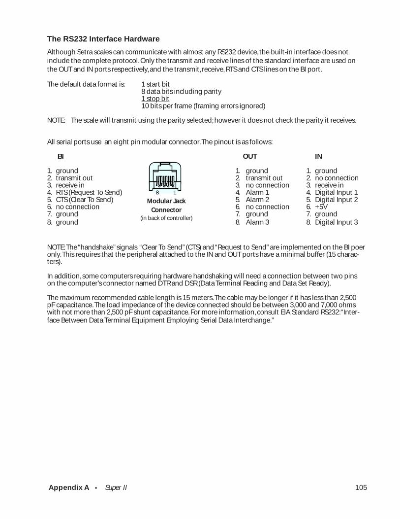
Appendix A • Super II 105
The RS232 Interface Hardware
Although Setra scales can communicate with almost any RS232 device, the built-in interface does notinclude the complete protocol. Only the transmit and receive lines of the standard interface are used onthe OUT and IN ports respectively, and the transmit, receive, RTS and CTS lines on the BI port.
The default data format is: 1 start bit8 data bits including parity1 stop bit10 bits per frame (framing errors ignored)
NOTE: The scale will transmit using the parity selected; however it does not check the parity it receives.
All serial ports use an eight pin modular connector. The pinout is as follows:
BI OUT IN
1. ground 1. ground 1. ground2. transmit out 2. transmit out 2. no connection3. receive in 3. no connection 3. receive in4. RTS (Request To Send) 4. Alarm 1 4. Digital Input 15. CTS (Clear To Send) 5. Alarm 2 5. Digital Input 26. no connection 6. no connection 6. +5V7. ground 7. ground 7. ground8. ground 8. Alarm 3 8. Digital Input 3
NOTE: The “handshake” signals “Clear To Send” (CTS) and “Request to Send” are implemented on the BI poeronly. This requires that the peripheral attached to the IN and OUT ports have a minimal buffer (15 charac-ters).
In addition, some computers requiring hardware handshaking will need a connection between two pinson the computer’s connector named DTR and DSR (Data Terminal Reading and Data Set Ready).
The maximum recommended cable length is 15 meters. The cable may be longer if it has less than 2,500pF capacitance. The load impedance of the device connected should be between 3,000 and 7,000 ohmswith not more than 2,500 pF shunt capacitance. For more information, consult EIA Standard RS232: “Inter-face Between Data Terminal Equipment Employing Serial Data Interchange.”
Modular Jack Connector
(in back of scale)
8 1
Modular JackConnector
(in back of controller)

Appendix B • Super II 106
Appendix B
ScriptCoderTM Custom Label PrintingYour Super II scale can be programmed to print custom label designs on any serial printer, limited only bythe printer’s capabilities. This feature, called ScriptCoder™, allows a label design or RS232 output, to bewritten using a series of codes which are stored in the scale’s memory. The set of codes, or script, is ex-ecuted each time the specific label design is selected to print. The script can be written to create a custom-ized output to a serial dot matrix printer, thermal bar code printer, or even a data collection device. TheSuper II can store up to ten different scripts.
Ways to Create and Store a ScriptA script contains preprogrammed text and data which is transmitted from the scale to the printer whenthe appropriate print command is executed. There are four ways to create and enter a script; the bestmethod to use depends on the complexity of the label design and the peripherals available to the pro-grammer.
The first method may be performed using only a Super II and involves entering codes directly through thescale keypad. The second method involves the use of a QWERTY keyboard to enter a combination ofcharacters and codes. The third method involves scanning codes into the scale using a bar code menuchart available in the ScriptCoder Label Design & Cable Kit (Setra P/N 404910). Finally, the fourth methodinvolves writing the script using the ScriptCoder PC program and downloading it to the scale via the BIRS232 port (also available with the ScriptCoder kit).
Entering a Script via the Super II KeypadAll of the codes required for a script may be entered directly through the scale keypad. This method ismost suitable for simple label designs as shown in the following examples:
Part #: 123-456APW: 2.56789 g
The following transmission sequence would be required from the scale:- transmit the text “Part #:” and one space- transmit the contents of the ID register- transmit one carriage return and one line feed- transmit the text “APW:” and one space- transmit the contents of the APW register and one space- transmit the unit designation letter- transmit one carriage return and one line feed (for longer spacing or to feed between labels add
linefeeds or a formfeed to the end of this script to advance to the next label)
Before a script can be entered into the scale’s print memory, the scale must be setup to accept the pro-gramming codes. To perform this setup, follow the instructions under soft key PRINT in the SupervisorSetups section of this manual. The following is the Script entry menu.
ENTER CODE PC BARCODE GO BACK
Enter each code or character now. PCto download script. BARCODE to scan.
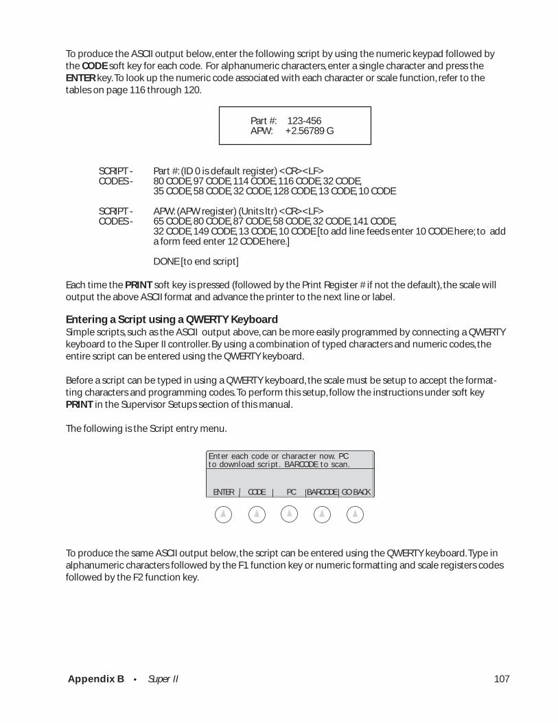
Appendix B • Super II 107
To produce the ASCII output below, enter the following script by using the numeric keypad followed bythe CODE soft key for each code. For alphanumeric characters, enter a single character and press theENTER key. To look up the numeric code associated with each character or scale function, refer to thetables on page 116 through 120.
Part #: 123-456APW: +2.56789 G
SCRIPT - Part #: (ID 0 is default register) <CR><LF>CODES - 80 CODE, 97 CODE, 114 CODE, 116 CODE, 32 CODE,
35 CODE, 58 CODE, 32 CODE, 128 CODE, 13 CODE, 10 CODE
SCRIPT - APW: (APW register) (Units ltr) <CR><LF>CODES - 65 CODE, 80 CODE, 87 CODE, 58 CODE, 32 CODE, 141 CODE,
32 CODE, 149 CODE, 13 CODE, 10 CODE [to add line feeds enter 10 CODE here; to adda form feed enter 12 CODE here.]
DONE [to end script]
Each time the PRINT soft key is pressed (followed by the Print Register # if not the default), the scale willoutput the above ASCII format and advance the printer to the next line or label.
Entering a Script using a QWERTY KeyboardSimple scripts, such as the ASCII output above, can be more easily programmed by connecting a QWERTYkeyboard to the Super II controller. By using a combination of typed characters and numeric codes, theentire script can be entered using the QWERTY keyboard.
Before a script can be typed in using a QWERTY keyboard, the scale must be setup to accept the format-ting characters and programming codes. To perform this setup, follow the instructions under soft keyPRINT in the Supervisor Setups section of this manual.
The following is the Script entry menu.
To produce the same ASCII output below, the script can be entered using the QWERTY keyboard. Type inalphanumeric characters followed by the F1 function key or numeric formatting and scale registers codesfollowed by the F2 function key.
ENTER CODE PC BARCODE GO BACK
Enter each code or character now. PCto download script. BARCODE to scan.
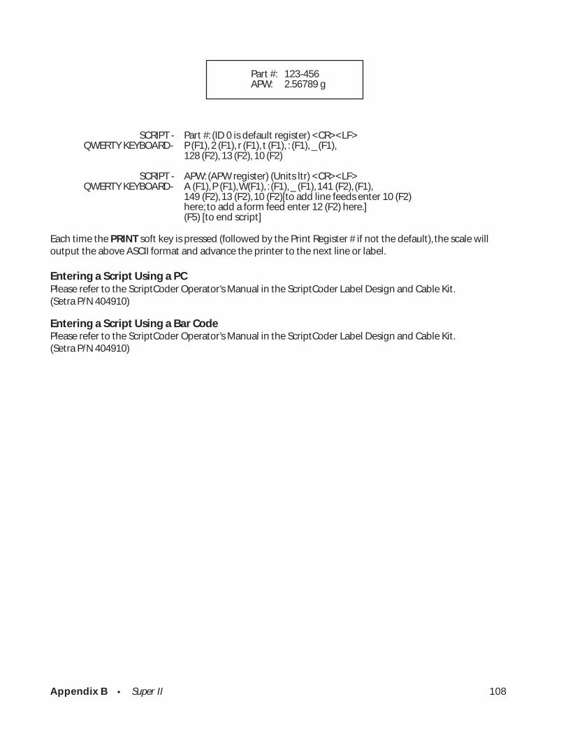
Appendix B • Super II 108
Part #: 123-456APW: 2.56789 g
SCRIPT - Part #: (ID 0 is default register) <CR><LF>QWERTY KEYBOARD- P (F1), 2 (F1), r (F1), t (F1), : (F1), _ (F1),
128 (F2), 13 (F2), 10 (F2)
SCRIPT - APW: (APW register) (Units ltr) <CR><LF>QWERTY KEYBOARD- A (F1), P (F1), W(F1), : (F1), _ (F1), 141 (F2), (F1),
149 (F2), 13 (F2), 10 (F2)[to add line feeds enter 10 (F2)here; to add a form feed enter 12 (F2) here.](F5) [to end script]
Each time the PRINT soft key is pressed (followed by the Print Register # if not the default), the scale willoutput the above ASCII format and advance the printer to the next line or label.
Entering a Script Using a PCPlease refer to the ScriptCoder Operator’s Manual in the ScriptCoder Label Design and Cable Kit.(Setra P/N 404910)
Entering a Script Using a Bar CodePlease refer to the ScriptCoder Operator’s Manual in the ScriptCoder Label Design and Cable Kit.(Setra P/N 404910)
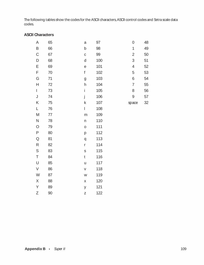
Appendix B • Super II 109
The following tables show the codes for the ASCII characters, ASCII control codes and Setra scale datacodes.
ASCII Characters
A 65 a 97 0 48
B 66 b 98 1 49
C 67 c 99 2 50
D 68 d 100 3 51
E 69 e 101 4 52
F 70 f 102 5 53
G 71 g 103 6 54
H 72 h 104 7 55
I 73 i 105 8 56
J 74 j 106 9 57
K 75 k 107 space 32
L 76 l 108
M 77 m 109
N 78 n 110
O 79 o 111
P 80 p 112
Q 81 q 113
R 82 r 114
S 83 s 115
T 84 t 116
U 85 u 117
V 86 v 118
W 87 w 119
X 88 x 120
Y 89 y 121
Z 90 z 122
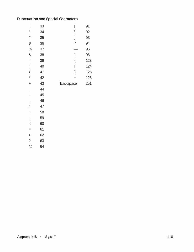
Appendix B • Super II 110
Punctuation and Special Characters
! 33 [ 91
“ 34 \ 92
# 35 ] 93
$ 36 ^ 94
% 37 — 95
& 38 ‘ 96
‘ 39 { 123
( 40 | 124
) 41 } 125
* 42 ~ 126
+ 43 backspace 251
, 44
- 45
. 46
/ 47
: 58
; 59
< 60
= 61
> 62
? 63
@ 64

Appendix B • Super II 111
Setra Scale Data
ID 0 128 transmit ID field 0 “S” id
ID 1 129 transmit ID field 1 “D” id
ID 2 130 transmit ID field 2 “R” id
ID 3 131 transmit ID field 3 “L” id
ID 4 132 transmit ID field 4 “N” id
ID 5 133 transmit ID field 5 “Y” id
ID 6 134 transmit ID field 6 “H” id time
ID 7 135 transmit ID field 7 “B” id
ID 8 136 transmit ID field 8 “U“ id
ID 9 137 transmit ID field 9 “F” id
Gross 138 transmit gross weight in external resolution
Net 139 transmit net weight in external resolution
Tare 140 transmit tare weight in external resolution
A.P.W. 141 transmit APW in internal resolution
A.P.W. exp. 142 transmit APW in exponential notation
Count 143 transmit count
Acc Count 144 transmit count accumulator value
Acc Ct Ents 145 transmit count accumulator entries
Acc Weight 146 transmit weight accumulator
Acc wt Ents 147 transmit weight accumulator entries
Units word 148 transmit units label, e.g., “grams” or “pounds”
Units ltr. 149 transmit units letter, e.g., “g” or “p”
Setra codes 150 ignored in scale, interpreted during setup to insert the appro-
priate scale control codes.
Units jump code 151 transmit units code number and J, e.g., “1J” or “3J”
X of “x or y seq.” 152 transmits the X of the “X of Y” sequence.
Y of “x or y seq.” 153 transmits the Y of the “X of Y” sequence.
Time 154 transmit the time hh:mm AM, from the Super II
Date 155 transmit the date mm/dd/yy from the Super II
Pause (.1) 156 Pause for a specified time before continuing to transmit the
script.
(Argument code 1 to 99, e.g., 5 = .5 second pause, 25 = 2.5
second pause.)
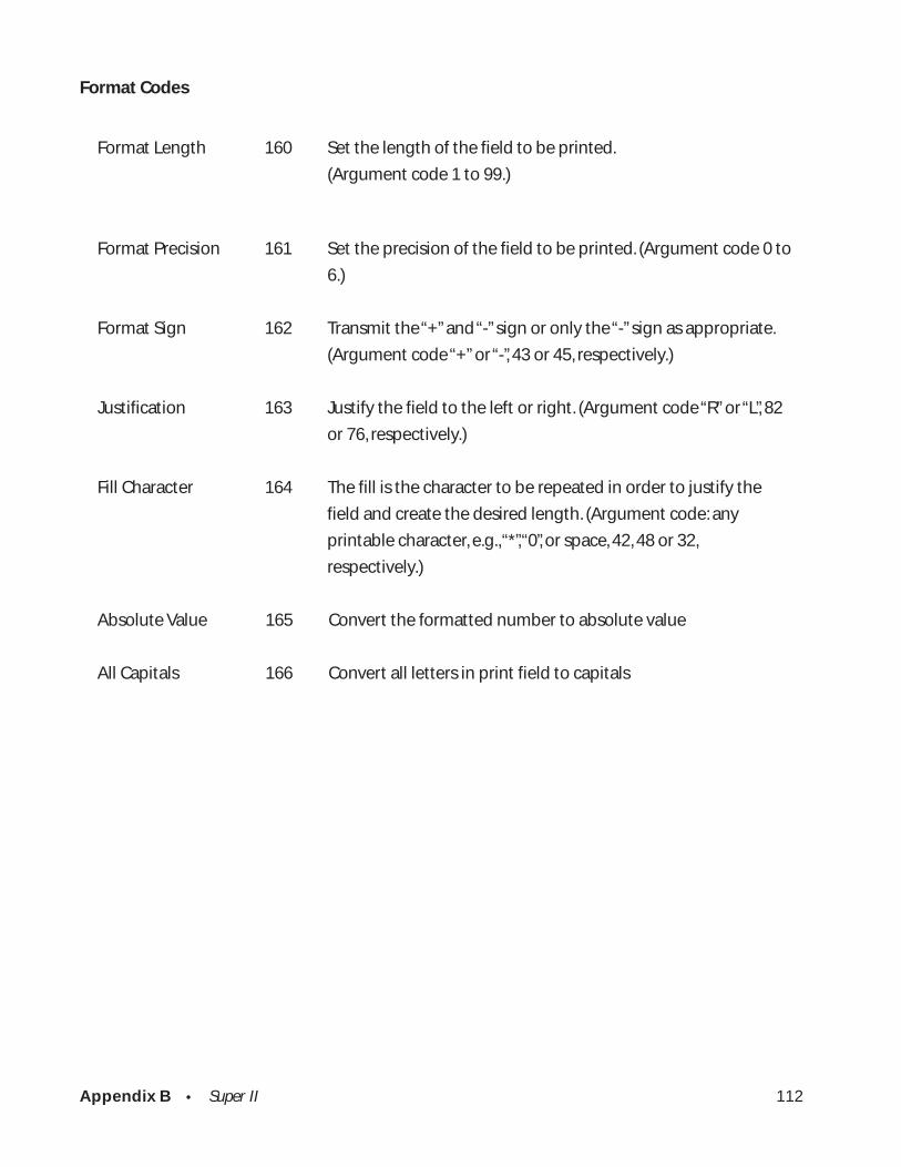
Appendix B • Super II 112
Format Codes
Format Length 160 Set the length of the field to be printed.
(Argument code 1 to 99.)
Format Precision 161 Set the precision of the field to be printed. (Argument code 0 to
6.)
Format Sign 162 Transmit the “+” and “-” sign or only the “-” sign as appropriate.
(Argument code “+” or “-”, 43 or 45, respectively.)
Justification 163 Justify the field to the left or right. (Argument code “R” or “L”, 82
or 76, respectively.)
Fill Character 164 The fill is the character to be repeated in order to justify the
field and create the desired length. (Argument code: any
printable character, e.g., “*”, “0”, or space, 42, 48 or 32,
respectively.)
Absolute Value 165 Convert the formatted number to absolute value
All Capitals 166 Convert all letters in print field to capitals

Appendix B • Super II 113
ASCII Control Characters
soh 1 ctrl A esc 27
stx 2 ctrl B fs 28
etx 3 ctrl C gs 29
eot 4 ctrl D rs 30
enq 5 ctrl E us 31
ack 6 ctrl F del 127
bel 7 ctrl G
bs 8 ctrl H
ht 9 ctrl I
lf 10 ctrl J
vt 11 ctrl K
ff 12 ctrl L
cr 13 ctrl M
so 14 ctrl N
si 15 ctrl O
dle 16 ctrl P
dcl 17 ctrl Q
dc2 18 ctrl R
dc3 19 ctrl S
dc4 20 ctrl T
nak 21 ctrl U
syn 22 ctrl V
etb 23 ctrl W
can 24 ctrl W
em 25 ctrl Y
sub 26 ctrl Z
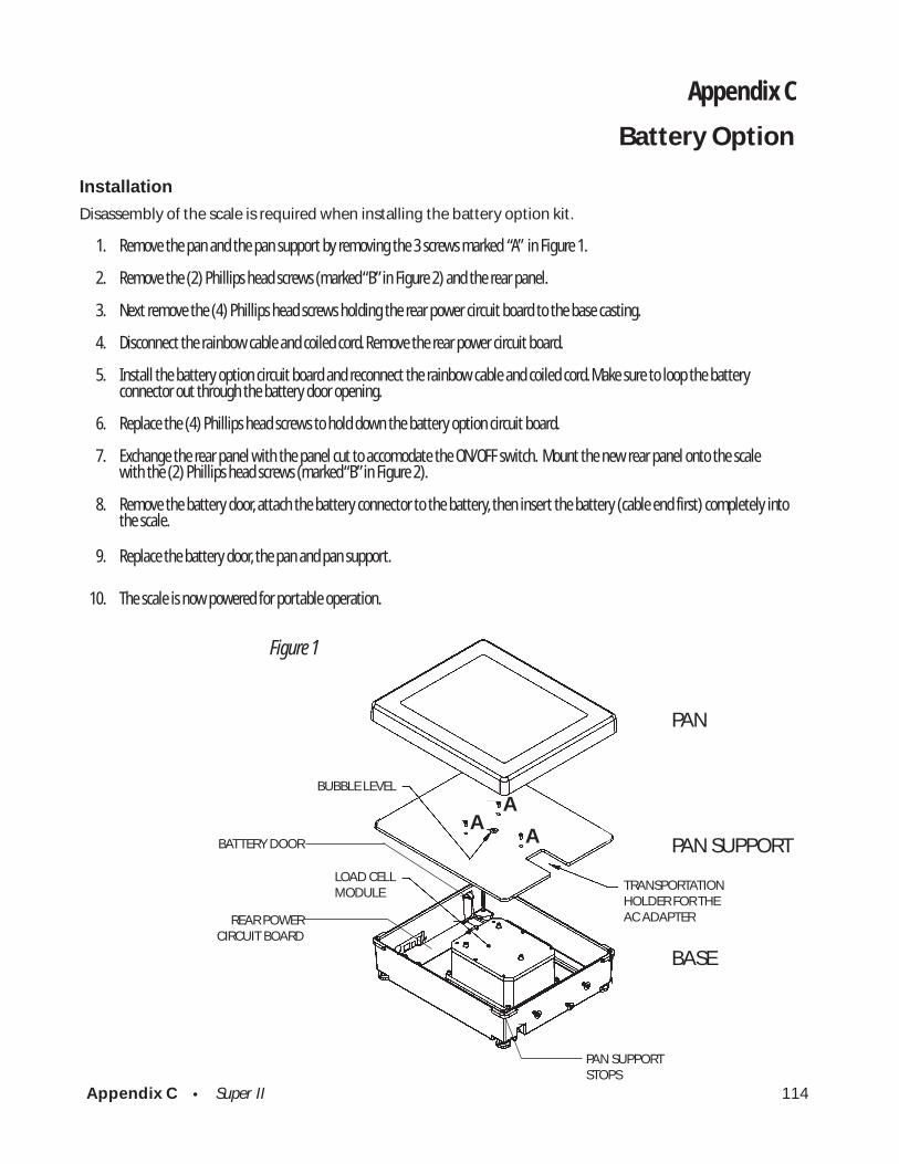
Appendix C • Super II 114
PAN
PAN SUPPORT
BASE
BUBBLE LEVEL
LOAD CELLMODULE
TRANSPORTATIONHOLDER FOR THEAC ADAPTER
PAN SUPPORTSTOPS
Figure 1
AA
ABATTERY DOOR
REAR POWERCIRCUIT BOARD
Appendix C
Battery Option
Installation
Disassembly of the scale is required when installing the battery option kit.
1. Remove the pan and the pan support by removing the 3 screws marked “A” in Figure 1.
2. Remove the (2) Phillips head screws (marked “B” in Figure 2) and the rear panel.
3. Next remove the (4) Phillips head screws holding the rear power circuit board to the base casting.
4. Disconnect the rainbow cable and coiled cord. Remove the rear power circuit board.
5. Install the battery option circuit board and reconnect the rainbow cable and coiled cord. Make sure to loop the batteryconnector out through the battery door opening.
6. Replace the (4) Phillips head screws to hold down the battery option circuit board.
7. Exchange the rear panel with the panel cut to accomodate the ON/OFF switch. Mount the new rear panel onto the scalewith the (2) Phillips head screws (marked “B” in Figure 2).
8. Remove the battery door, attach the battery connector to the battery, then insert the battery (cable end first) completely intothe scale.
9. Replace the battery door, the pan and pan support.
10. The scale is now powered for portable operation.
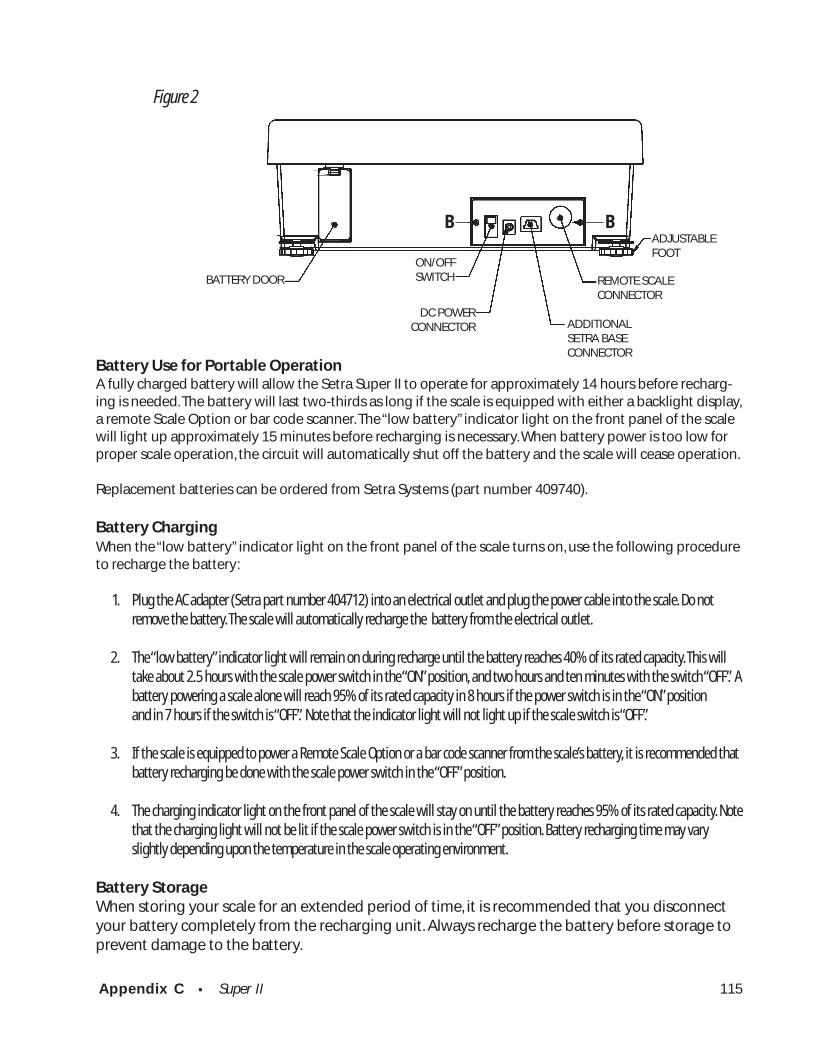
Appendix C • Super II 115
Battery Use for Portable OperationA fully charged battery will allow the Setra Super II to operate for approximately 14 hours before recharg-ing is needed. The battery will last two-thirds as long if the scale is equipped with either a backlight display,a remote Scale Option or bar code scanner. The “low battery” indicator light on the front panel of the scalewill light up approximately 15 minutes before recharging is necessary. When battery power is too low forproper scale operation, the circuit will automatically shut off the battery and the scale will cease operation.
Replacement batteries can be ordered from Setra Systems (part number 409740).
Battery ChargingWhen the “low battery” indicator light on the front panel of the scale turns on, use the following procedureto recharge the battery:
1. Plug the AC adapter (Setra part number 404712) into an electrical outlet and plug the power cable into the scale. Do notremove the battery. The scale will automatically recharge the battery from the electrical outlet.
2. The “low battery” indicator light will remain on during recharge until the battery reaches 40% of its rated capacity. This willtake about 2.5 hours with the scale power switch in the “ON” position, and two hours and ten minutes with the switch “OFF”. Abattery powering a scale alone will reach 95% of its rated capacity in 8 hours if the power switch is in the “ON” positionand in 7 hours if the switch is “OFF”. Note that the indicator light will not light up if the scale switch is “OFF”.
3. If the scale is equipped to power a Remote Scale Option or a bar code scanner from the scale’s battery, it is recommended thatbattery recharging be done with the scale power switch in the “OFF” position.
4. The charging indicator light on the front panel of the scale will stay on until the battery reaches 95% of its rated capacity. Notethat the charging light will not be lit if the scale power switch is in the “OFF” position. Battery recharging time may varyslightly depending upon the temperature in the scale operating environment.
Battery StorageWhen storing your scale for an extended period of time, it is recommended that you disconnectyour battery completely from the recharging unit. Always recharge the battery before storage toprevent damage to the battery.
B B
Figure 2
ADJUSTABLEFOOT
REMOTE SCALECONNECTOR
ADDITIONALSETRA BASECONNECTOR
ON/OFFSWITCH
DC POWERCONNECTOR
BATTERY DOOR

Appendix D • Super II 116
PAN
PAN SUPPORT
BASE
LOAD CELLMODULE
Figure 1. Exploded view o f Super II bef ore Remote Scale Option Installation
A
REMOTE CONNECTORPLUG
AA
REMOTE OPTION A TO DCIRCUIT BOARD
LOCATION FRONT
Appendix D
Strain Gauge Load Cell Remote Scale Option
Installation
Disassembly of the scale is required when installing the optional strain gauge load cell base analog todigital signal conversion PCB.
1. Remove the pan and the pan support by removing the 3 screws marked “A” in Figure 1.
2. Pop out the round connector plug from the hole marked “Remote Base” on the back cover.
3. Locate the two threaded holes in the left side of the bottom of the base casting (as viewed from the front of the base). Start a 6-32 x 3/8”screw into each of the holes and turn them two revolutions each.
4. Refer to Figure 2. Pick up the circuit board and bracket assembly and orient it so that the flange with two slots is downward and the 6-pinDIN connector faces the back. Lift the coil cord upward to the left and insert the bracket assembly into the base casting between the coilcord and the load cell assembly, so that the straight section of the cord is against the back edge of the bracket assembly above the DINconnector (circuit board face the load cell assembly).
5. Slide the circuit board back until the bottom of the bracket touches the back of the base casting and then slide the bracket to the left sothat the flange slots slide around on the 6-32 x 3/8” screws. The coil cord should lie beween the bracket and the left side of the basecasting.
6. Tighten down the 6-32 x 3/8” screws to hold the bracket in place.
7. Connect the Strain Gauge Remote Scale Option circuit board cable to the 10 pin header between the two RJ-45 jacks on the Rear PowerCircuit Board.
8. Reinstall the pan and pan support with the 3 screws.
9. The scale is now ready for Remote Base calibration and operation.

Appendix D • Super II 117
Connector Wiring
If the cable connector of the remote scale base is physically compatible with the 6 pin circular DIN connec-tor on the back of the Super II scale, proceed to Figures 4 and 5 to verify that it is electrically compatible.Otherwise, damage may be caused to both the Super II scale and the remote scale base.
If the cable connector of the remote scale base is not compatible with the 6 pin circular DIN connector onthe back of the Super II scale, follow the procedures directly below.
NOTE: DISCONNECT THE SUPER II SCALE AND REMOTE SCALE BASE FROM ITS POWER SOURCE BEFOREPERFORMING THE FOLLOWING PROCEDURES.
1. Remove the existing remote scale base connector.
2. Taking the connector supplied, separate the cord guard and metal housing by removing the screw.
3. Slide the metal housing onto the cable of the remote scale base. (See Figure 3.)
4. Strip 1/2" of the cable insulation.
NOTE: Do not nick, scrape or cut foil or braided shield when stripping cable insulation. Be equallycareful not to mar the wire insulation when stripping the shield or conductors when stripping thewire insulation.
COIL CABLE
REMOTE SCALE OPTIONCIRCUIT BOARD CABLE
RSO MOUNTING SCREWS
RSO MOUNTING BRACKET
RSO CIRCUIT BOARD ..
..
Figure 2. Overview of Remote Scale Option Installation
FRONT OF SCALE
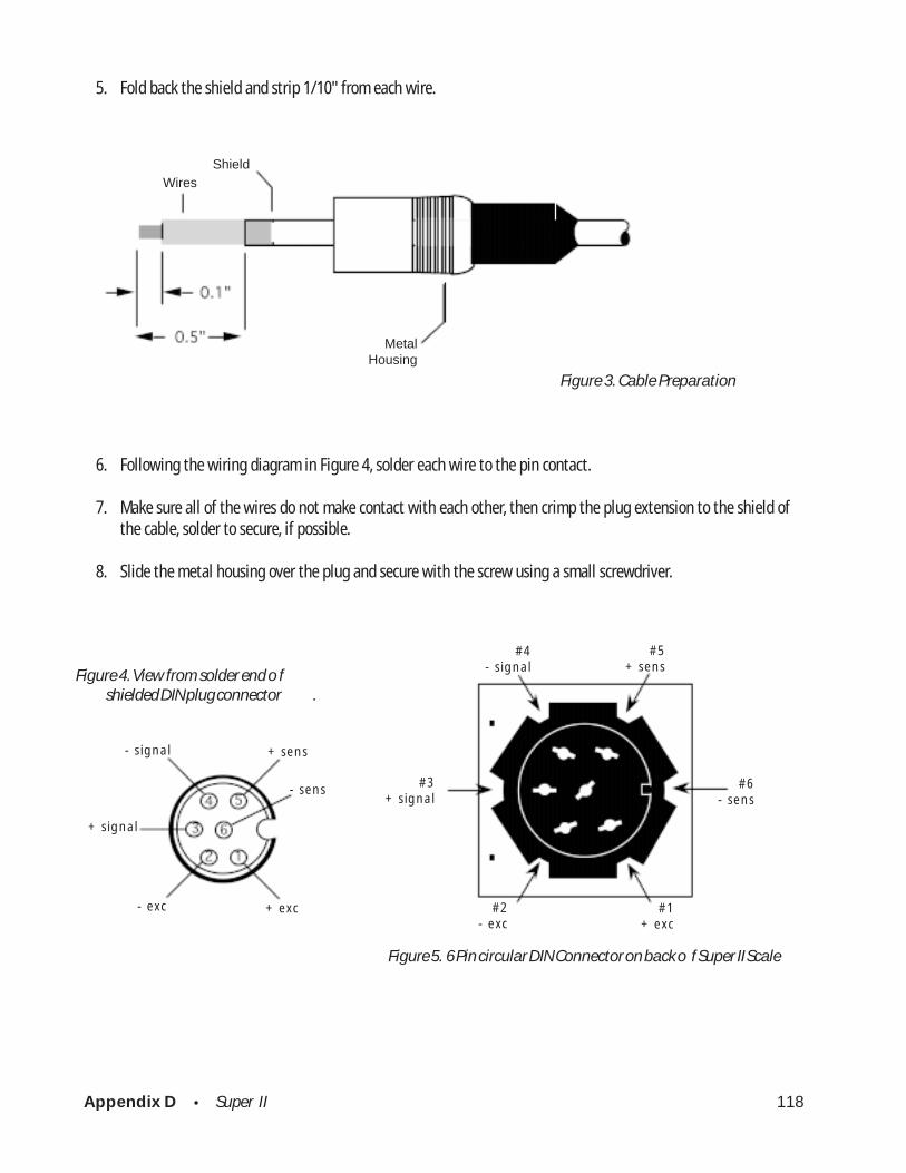
Appendix D • Super II 118
5. Fold back the shield and strip 1/10" from each wire.
Figure 3. Cable Preparation
6. Following the wiring diagram in Figure 4, solder each wire to the pin contact.
7. Make sure all of the wires do not make contact with each other, then crimp the plug extension to the shield ofthe cable, solder to secure, if possible.
8. Slide the metal housing over the plug and secure with the screw using a small screwdriver.
Figure 5. 6 Pin circular DIN Connector on back o f Super II Scale
Figure 4. View from solder end o f shielded DIN plug connector .
#4- signal
#5+ sens
#3 + signal
#6- sens
#1+ exc
#2- exc
WiresShield
MetalHousing
- signal
+ signal
+ sens
- sens
+ exc- exc

Appendix D • Super II 119
CalibrationThe calibration of the Strain Gauge Load Cell Remote Scale Option is accessed through the BASECOM softkey of the CALIB menu in the Bases Setups (see CALIB section in this manual). Before entering theBASECOM selections, make sure that the controller is monitoring the Strain Gauge Load Cell Remote Baseby entering the proper Base address number with the remote key.
Upon entering the BASECOM mode, the following screen will appear:(User input is shown in bold)
Press 2 and then press ENTER.
Press the Yes soft key.
Press the number for the desired units (1-4) followed by ENTER.
Using the numeric keys enter the value of the full scale capacity in theselected weight unit and press ENTER.
NO YES ENTER END
Select calibration units and press ENTER1) Grams2) Kilograms3) Pounds4) Ounces
NO YES ENTER END
Enter full scale capacity of theremote base and press ENTER
NO YES ENTER END
Select a function and press ENTER1) Test modes2) Calibration3) Set sampling res.4) Escape
NO YES ENTER END
Present calibration data will be lost.Continue calibration?(enter YES or NO)
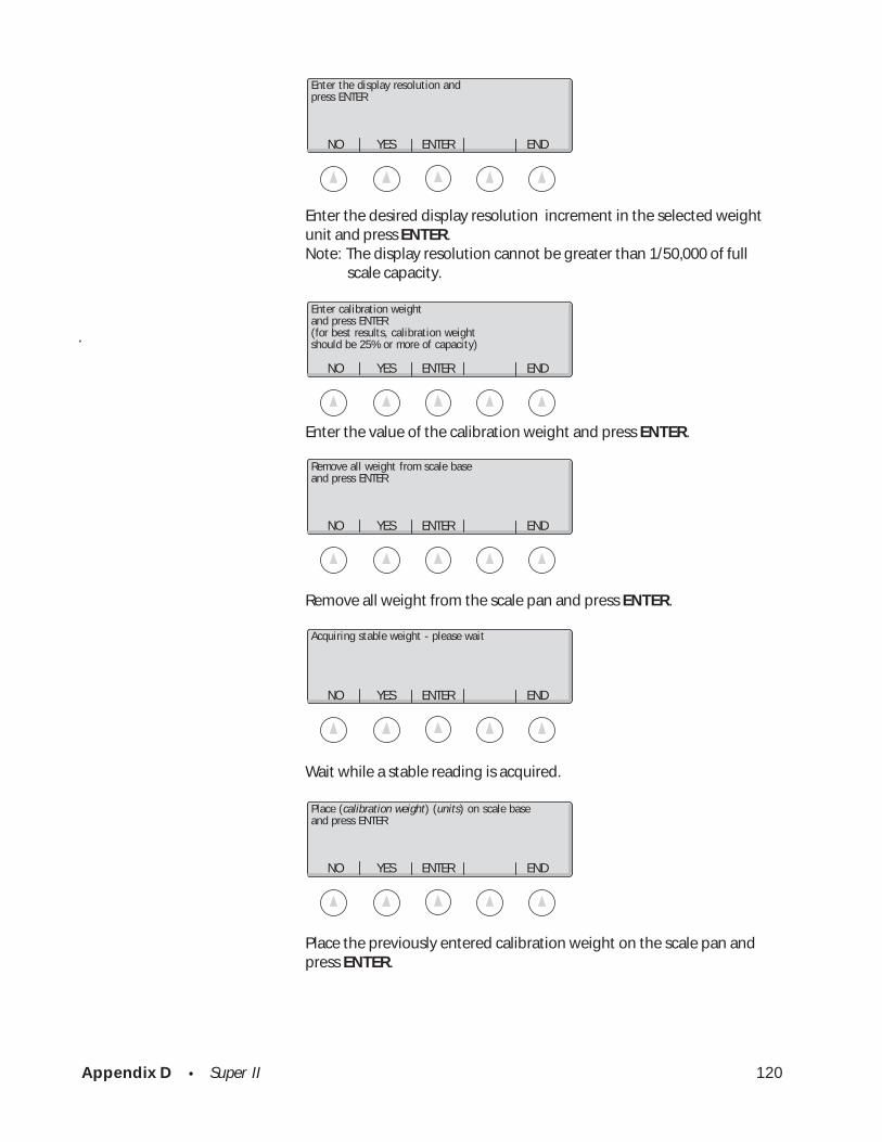
Appendix D • Super II 120
Enter the desired display resolution increment in the selected weightunit and press ENTER.Note: The display resolution cannot be greater than 1/50,000 of full
scale capacity.
.
Enter the value of the calibration weight and press ENTER.
Remove all weight from the scale pan and press ENTER.
Wait while a stable reading is acquired.
Place the previously entered calibration weight on the scale pan andpress ENTER.
NO YES ENTER END
Enter calibration weightand press ENTER(for best results, calibration weightshould be 25% or more of capacity)
NO YES ENTER END
Enter the display resolution andpress ENTER
NO YES ENTER END
Remove all weight from scale baseand press ENTER
NO YES ENTER END
Acquiring stable weight - please wait
NO YES ENTER END
Place (calibration weight) (units) on scale baseand press ENTER
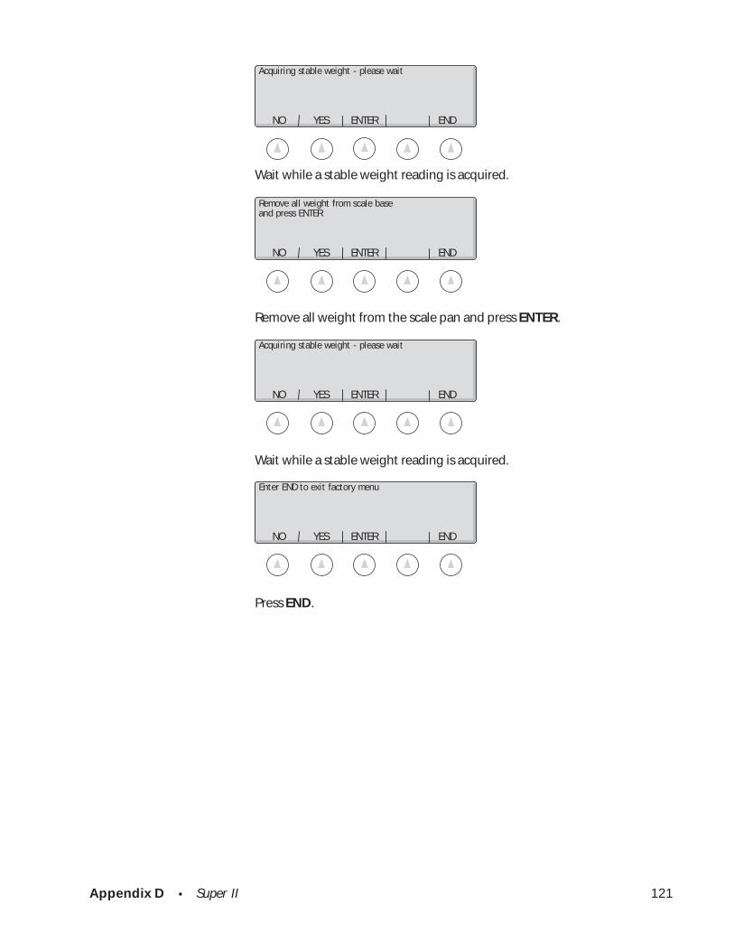
Appendix D • Super II 121
Wait while a stable weight reading is acquired.
Remove all weight from the scale pan and press ENTER.
Wait while a stable weight reading is acquired.
Press END.
NO YES ENTER END
Acquiring stable weight - please wait
NO YES ENTER END
Remove all weight from scale baseand press ENTER
NO YES ENTER END
Acquiring stable weight - please wait
NO YES ENTER END
Enter END to exit factory menu
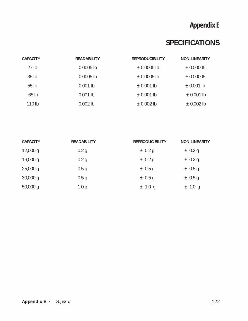
Appendix E • Super II 122
Appendix E
SPECIFICATIONS
CAPACITY READABILITY REPRODUCIBILITY NON-LINEARITY
27 lb 0.0005 lb ± 0.0005 lb ± 0.00005
35 lb 0.0005 lb ± 0.0005 lb ± 0.00005
55 lb 0.001 lb ± 0.001 lb ± 0.001 lb
65 lb 0.001 lb ± 0.001 lb ± 0.001 lb
110 lb 0.002 lb ± 0.002 lb ± 0.002 lb
CAPACITY READABILITY REPRODUCIBILITY NON-LINEARITY
12,000 g 0.2 g ± 0.2 g ± 0.2 g
16,000 g 0.2 g ± 0.2 g ± 0.2 g
25,000 g 0.5 g ± 0.5 g ± 0.5 g
30,000 g 0.5 g ± 0.5 g ± 0.5 g
50,000 g 1.0 g ± 1.0 g ± 1.0 g
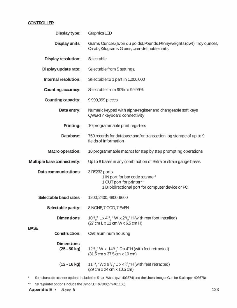
Appendix E • Super II 123
CONTROLLER
Display type:
Display units:
Display resolution:
Display update rate:
Internal resolution:
Counting accuracy:
Counting capacity:
Data entry:
Printing:
Database:
Macro operation:
Multiple base connectivity:
Data communications:
Selectable baud rates:
Selectable parity:
Dimensions:
BASEConstruction:
Dimensions:(25 - 50 kg)
(12 - 16 kg)
Graphics LCD
Grams, Ounces (avoir du poids), Pounds, Pennyweights (dwt), Troy ounces,Carats, Kilograms, Grains, User-definable units
Selectable
Selectable from 5 settings.
Selectable to 1 part in 1,000,000
Selectable from 90% to 99.99%
9,999,999 pieces
Numeric keypad with alpha-register and changeable soft keysQWERTY keyboard connectivity
10 programmable print registers
750 records for database and/or transaction log storage of up to 9fields of information
10 programmable macros for step by step prompting operations
Up to 8 bases in any combination of Setra or strain gauge bases
3 RS232 ports:1 IN port for bar code scanner*1 OUT port for printer**1 BI bidirectional port for computer device or PC
1200, 2400, 4800, 9600
8 NONE, 7 ODD, 7 EVEN
101/2” L x 41/
2 “ W x 21/
2” H (with rear foot installed)
(27 cm L x 11 cm W x 6.5 cm H)
Cast aluminum housing
121/2 “ W x 143/
4”
D x 4” H (with feet retracted)
(31.5 cm x 37.5 cm x 10 cm)
11 1/2 “W x 9 1/
4”D x 4 3/
4”H (with feet retracted)
(29 cm x 24 cm x 10.5 cm)
* Setra barcode scanner options include the Smart Wand (p/n 403674) and the Linear Imager Gun for Scale (p/n 403678).
** Setra printer options include the Dyno SETRA 300(p/n 401160).
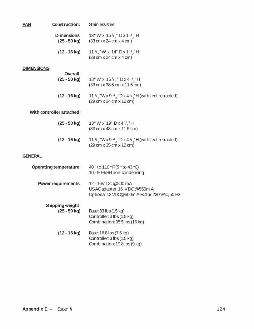
Appendix E • Super II 124
PAN Construction:
Dimensions:(25 - 50 kg)
(12 - 16 kg)
DIMENSIONSOverall:
(25 - 50 kg)
(12 - 16 kg)
With controller attached:
(25 - 50 kg)
(12 - 16 kg)
GENERAL
Operating temperature:
Power requirements:
Shipping weight:(25 - 50 kg)
(12 - 16 kg)
Stainless steel
13 “ W x 15 1/
4”
D x 1 1/
2” H
(33 cm x 24 cm x 4 cm)
11 1/2 “ W x 14”
D x 1 1/
2” H
(29 cm x 24 cm x 4 cm)
13 “ W x 15 1/
4 ”
D x 4 1/
2” H
(33 cm x 38.5 cm x 11.5 cm)
11 1/2 “W x 9 1/
2 ”D x 4 3/
4”H (with feet retracted)
(29 cm x 24 cm x 12 cm)
13 “ W x 19”
D x 4 1/
2” H
(33 cm x 48 cm x 11.5 cm)
11 1/2 “W x 9 1/
2 ”D x 4 3/
4”H (with feet retracted)
(29 cm x 35 cm x 12 cm)
40 o to 110 o F (5 o to 43 oC)10 - 90% RH non-condensing
12 - 16V DC @ 800 mAUS AC adapter: 16 V DC @ 550m AOptional 12 VDC@ 500m A EC fpr 230 VAC, 50 Hz
Base: 33 lbs (15 kg)Controller: 3 lbs (1.5 kg)Combination: 35.5 lbs (16 kg)
Base: 16.8 lbs (7.5 kg)Controller: 3 lbs (1.5 kg)Combination: 19.8 lbs (9 kg)

Appendix F • Super II 125
Appendix F
Glossary of Terms
Accuracy The degree of conformity of a measured value to the true value.
APW A scale feature whereby the scale uses a preliminary average piece weight toEnhancement count parts, allowing the operator to increase the sample size without hand
counting. When the targeted sample size is obtained the average pieceweight is recalculated for final counting with greater precision.
Average The value calculated by dividing the quantity of parts in the sample into thePiece Weight weight of the sample. This value is stored in the scale and divided into the
weight of the bulk load to provide a total count.
Base The portion of the scale that receives the load to be weighed.
Baud Rate The rate at which a scale transmits or receives information to or from acomputer or peripheral device.
Controller The portion of the scale that includes the keypad, display, battery status LED’sand ports for communicating with the scale base and peripheral devices.
Counting The largest number of pieces that can be shown on the controller’s display.Capacity
Counting (Also, “internal counting resolution” or “internal resolution”)The ratio of aResolution scale’s capacity to the weight of the lightest part placed on a scale’s weighing
element which can be counted in increments of one part.
Displayed The ratio of the weighing capacity of the scale to its readablility.Resolution
Display The tendency of a scale, with a fluctuating reading, to stabilize on the mostHysteresis consistent value.
Dual A counting system usually involving a low capacity local base for samplingScale System and a high capacity remote base for weighing the bulk load.
Gross Weight The weight of the contents (net weight) combined with the weight of itscontainer (tare weight).
ID Abbreviation for “identifier”. An identifier can be a part number, lot number, oritem description and can be entered into one of several available fields in the database.
Kitting The counting procedure that involves repeatedly counting out small quantities of agiven part to be packaged with other parts that will be used together in an assembly.
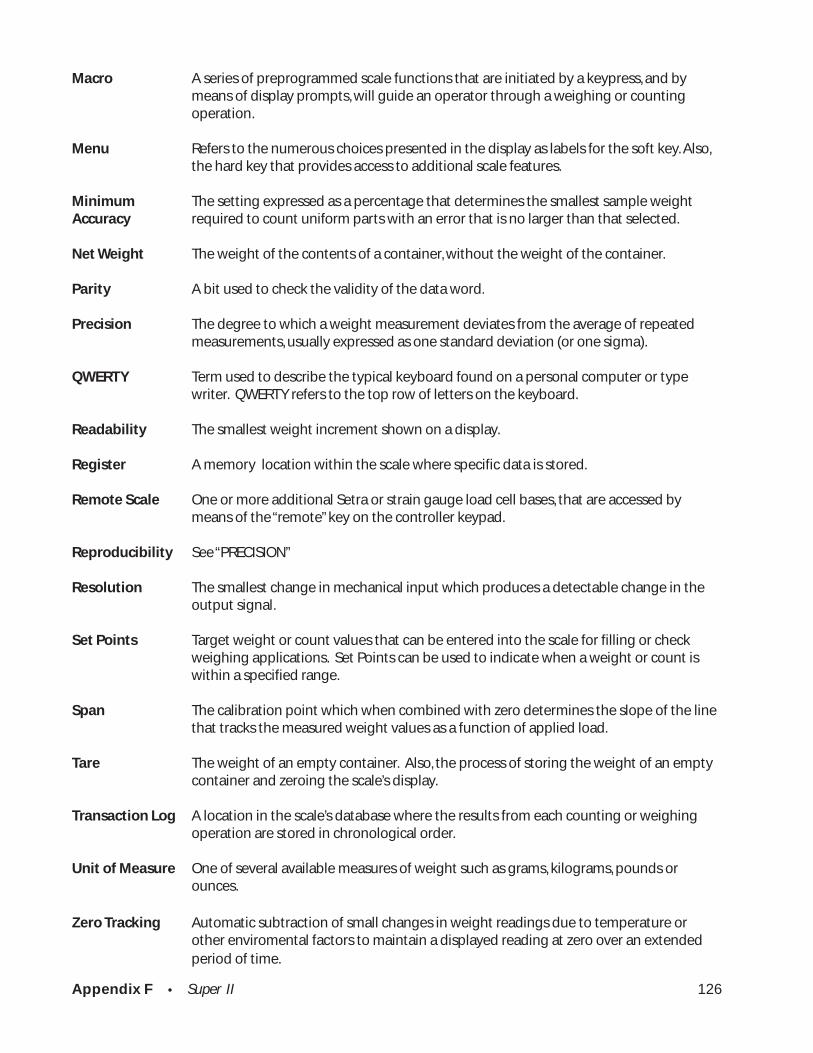
Appendix F • Super II 126
Macro A series of preprogrammed scale functions that are initiated by a keypress, and bymeans of display prompts, will guide an operator through a weighing or countingoperation.
Menu Refers to the numerous choices presented in the display as labels for the soft key. Also,the hard key that provides access to additional scale features.
Minimum The setting expressed as a percentage that determines the smallest sample weightAccuracy required to count uniform parts with an error that is no larger than that selected.
Net Weight The weight of the contents of a container, without the weight of the container.
Parity A bit used to check the validity of the data word.
Precision The degree to which a weight measurement deviates from the average of repeatedmeasurements, usually expressed as one standard deviation (or one sigma).
QWERTY Term used to describe the typical keyboard found on a personal computer or typewriter. QWERTY refers to the top row of letters on the keyboard.
Readability The smallest weight increment shown on a display.
Register A memory location within the scale where specific data is stored.
Remote Scale One or more additional Setra or strain gauge load cell bases, that are accessed bymeans of the “remote” key on the controller keypad.
Reproducibility See “PRECISION”
Resolution The smallest change in mechanical input which produces a detectable change in theoutput signal.
Set Points Target weight or count values that can be entered into the scale for filling or checkweighing applications. Set Points can be used to indicate when a weight or count iswithin a specified range.
Span The calibration point which when combined with zero determines the slope of the linethat tracks the measured weight values as a function of applied load.
Tare The weight of an empty container. Also, the process of storing the weight of an emptycontainer and zeroing the scale’s display.
Transaction Log A location in the scale’s database where the results from each counting or weighingoperation are stored in chronological order.
Unit of Measure One of several available measures of weight such as grams, kilograms, pounds orounces.
Zero Tracking Automatic subtraction of small changes in weight readings due to temperature orother enviromental factors to maintain a displayed reading at zero over an extendedperiod of time.

Appendix G • Super II 127
Appendix G
Setra Systems, Inc.Limited Two-Year Scale Warranty
Setra Systems, Inc. warrants the scales it manufactures to be free from defects in material and workman-ship. Upon return, transportation charges prepaid, to Setra’s factory within two (2) years of the date ofpurchase, Setra will repair or replace, at its option, any scale which it determines to contain defectivematerial or workmanship and will return said scale to purchaser, transportation prepaid, at any point in theUnited States. Setra shall not be obligated, however, to repair or replace scales which have been repairedby unauthorized parties, abused, improperly installed, altered, or otherwise misused or damaged, even if byaccident, in any way. Setra will not be responsible for any dismantling, reassembly or reinstallation charge.
Nothing in this warranty shall be construed as a warranty for merchantability or fitness for any specific useor purpose, and this warranty is in lieu of all other warranties, express or implied. Setra shall not be heldliable under the terms of this warranty for any special, indirect, incidental or consequential damagesclaimed in connection with the scale’s performance or availability.
Setra Systems, Inc.Weighing Systems Division159 Swanson RoadBoxborough, MA 01719(978) 263-14001 (800) 257-3872Fax (978) 635-9551
.
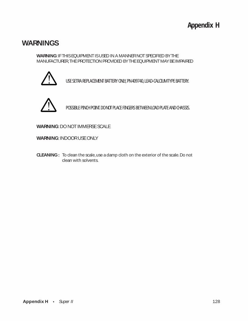
Appendix H • Super II 128
Appendix H
WARNINGS
WARNING: IF THIS EQUIPMENT IS USED IN A MANNER NOT SPECIFIED BY THEMANUFACTURER, THE PROTECTION PROVIDED BY THE EQUIPMENT MAY BE IMPAIRED
USE SETRA REPLACEMENT BATTERY ONLY, PN 409740, LEAD-CALCIUM TYPE BATTERY.
POSSIBLE PINCH POINT. DO NOT PLACE FINGERS BETWEEN LOAD PLATE AND CHASSIS.
WARNING: DO NOT IMMERSE SCALE
WARNING: INDOOR USE ONLY
CLEANING : To clean the scale, use a damp cloth on the exterior of the scale. Do notclean with solvents.
!
!

FCC WarningThis equipment has been tested and found to comply with the limits for a Class A digitaldevice pursuant to Part 15 of FCC Rules. These limits are designed to provide reasonableprotection against harmful interference when this equipment is operated in a commercialenvironment. This equipment generates, uses, and can radiate radio frequency energy and,if not installed and used in accordance with the instruction manual, may cause harmfulinterference to radio communications. Operation of this equipment in a residential areamay cause harmful interference, in which case, the user must correct the interference.
Canadian Department of CommunicationsThis digital apparatus does not exceed the Class A limits for radio noise emissions from adigital apparatus set out in the Radio Interference Regulations of the Canadian Depart-ment of Communications.Le présent appareil numerique n’emét pas de bruits radioeléctriques depassant les limitésapplicables aux appareils numeriques de la classe a préscrites dans le reglément sur lebrouillage Radioeléctrique edicté par le Ministre des Communications du Canada.

EC Declaration of Conformity
The product manufacturer,
Setra Systems, Inc.159 Swanson RoadBoxborough, Massachusetts 01719U.S.A.
declares under its sole responsibility that the product,Super IITM Electronic Weighing and Counting Scaleto which the declaration relates is in conformity with the following Europeanharmonized and published standards as of the date of this declaration;
EN61326 (CISPR 11, Group 1, Class B) Electronic Equipment for Measurement, Control,and Laboratory Use EMC Requirements
EN55022/CISPR 16:1992 Radiated Emissions,30 – 230 MHz, 30dBmV/m @ 10m230-1000MHz, 37dBmV/m @ 10m
EN55022/CISPR 16:1992 Conducted Emissions,150kHz - 0.5MHz 66-56dB(mV) QP, 56-46dB(mV) AV0.5MHz – 5MHz 60dB(mV) QP, 50dB(mV) AV5MHz – 30MHz 56dB(mV) QP, 46dB(mV) AV
EN61000-3-2:1995 Harmonized EmissionsEN61000-3-3:1995 Flicker EmissionsEN61000-4-2:1995 Electrostatic Discharge 4kV contact and 8kVAir Discharge Performance Criteria BEN61000-4-3:1996 Electromagnetic Field Immunity, 3V, 80%AM Modulated at 1kHz, Performance Criteria AEN61000-4-5:1995 Surges on AC Power Mains, 0.5kV Differential,1kV Common Mode, Performance Criteria BEN61000-4-6:1996 Conducted RF Current Injection on ACPower Mains, 3Vrms, Performance Criteria AEN61000-4-11:1994 Voltage Dips and Interuptions on AC PowerMains, 0.5 Cycle Each Polarity, 100%EN61010-1:1993 Safety Requirements for Electrical Equipmentfor Measurement, Control, and Laboratory Use
These conclusions are based on test report:EN61326: 1998 TEST Report for Setra Systems on the Super II Scale with BacklightingModel(s)409andEN61326 (CISPR 11, Group 1, Class B) Emissions T esting Performed on the SetraSystems W eighing Scale, Model 409, Super II with Backlighting Option
Technical Information File is maintained at:Setra Systems, Inc.159 Swanson RoadBoxborough, Massachusetts 01719U.S.A.Tel: (978) 263-1400Fax: (978) 635-9551
Year of CE Marking: 2001
I do hereby declare that the product specified above conforms to the listeddirectives and standards.
James J. VecchioVice PresidentWeighing Systems DivisionSetra Systems, Inc.
This Declaration of Conformityis in accord
with European Standard EN 45014General Criteria for Supplier’s
Declaration of Conformity.The basis for the criteria can be found in
international documentation, particularly inISO/IEC, Guide 22, 1982, Information onManufacturer’s Declaration of Conformityconcerning standards and other technical
specifications.
This declaration is anEC Type Declaration of Conformity
as referenced in article 10.1 ofEC directive 89/336/EEC
The EMC-directiveand as in Appendix III.B of
EC directive 73/23/EECThe Low Voltage Directive
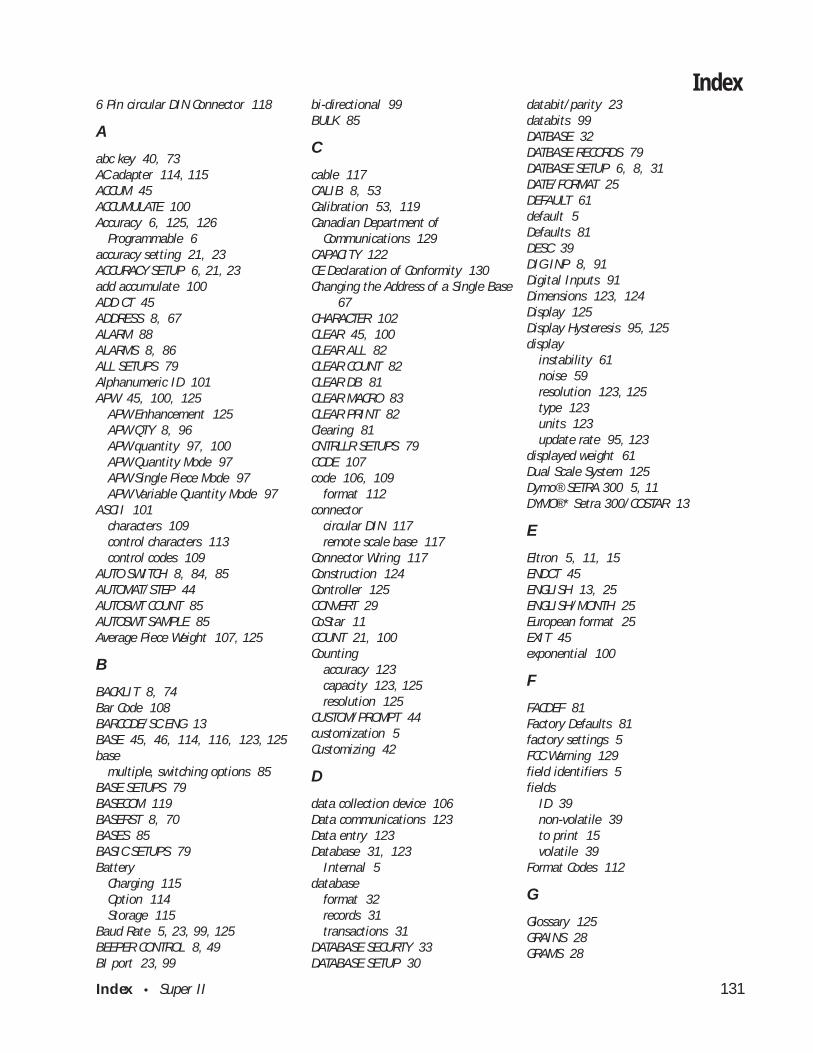
Index • Super II 131
6 Pin circular DIN Connector 118
A
abc key 40, 73AC adapter 114, 115ACCUM 45ACCUMULATE 100Accuracy 6, 125, 126
Programmable 6accuracy setting 21, 23ACCURACY SETUP 6, 21, 23add accumulate 100ADD CT 45ADDRESS 8, 67ALARM 88ALARMS 8, 86ALL SETUPS 79Alphanumeric ID 101APW 45, 100, 125
APW Enhancement 125APW QTY 8, 96APW quantity 97, 100APW Quantity Mode 97APW Single Piece Mode 97APW Variable Quantity Mode 97
ASCII 101characters 109control characters 113control codes 109
AUTO SWITCH 8, 84, 85AUTOMAT/STEP 44AUTOSWT COUNT 85AUTOSWT SAMPLE 85Average Piece Weight 107, 125
B
BACKLIT 8, 74Bar Code 108BARCODE/SC ENG 13BASE 45, 46, 114, 116, 123, 125base
multiple, switching options 85BASE SETUPS 79BASECOM 119BASERST 8, 70BASES 85BASIC SETUPS 79Battery
Charging 115Option 114Storage 115
Baud Rate 5, 23, 99, 125BEEPER CONTROL 8, 49BI port 23, 99
bi-directional 99BULK 85
C
cable 117CALIB 8, 53Calibration 53, 119Canadian Department of
Communications 129CAPACITY 122CE Declaration of Conformity 130Changing the Address of a Single Base
67CHARACTER 102CLEAR 45, 100CLEAR ALL 82CLEAR COUNT 82CLEAR DB 81CLEAR MACRO 83CLEAR PRINT 82Clearing 81CNTRLLR SETUPS 79CODE 107code 106, 109
format 112connector
circular DIN 117remote scale base 117
Connector Wiring 117Construction 124Controller 125CONVERT 29CoStar 11COUNT 21, 100Counting
accuracy 123capacity 123, 125resolution 125
CUSTOM/PROMPT 44customization 5Customizing 42
D
data collection device 106Data communications 123Data entry 123Database 31, 123
Internal 5database
format 32records 31transactions 31
DATABASE SECURTY 33DATABASE SETUP 30
databit/parity 23databits 99DATBASE 32DATBASE RECORDS 79DATBASE SETUP 6, 8, 31DATE/FORMAT 25DEFAULT 61default 5Defaults 81DESC 39DIG INP 8, 91Digital Inputs 91Dimensions 123, 124Display 125Display Hysteresis 95, 125display
instability 61noise 59resolution 123, 125type 123units 123update rate 95, 123
displayed weight 61Dual Scale System 125Dymo® SETRA 300 5, 11DYMO®* Setra 300/COSTAR 13
E
Eltron 5, 11, 15ENDCT 45ENGLISH 13, 25ENGLISH/MONTH 25European format 25EXIT 45exponential 100
F
FACDEF 81Factory Defaults 81factory settings 5FCC Warning 129field identifiers 5fields
ID 39non-volatile 39to print 15volatile 39
Format Codes 112
G
Glossary 125GRAINS 28GRAMS 28
Index
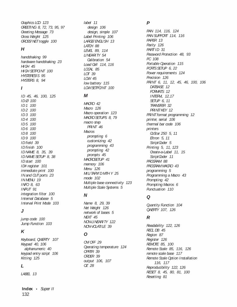
Index • Super II 132
Graphics LCD 123GREETING 8, 72, 73, 95, 97Greeting Message 73Gross Weight 125GROSS/NET toggle 100
H
handshaking 99hardware handshaking 23HIGH 45HIGH SETPOINT 100HYSTERESIS 95HYSTERS 8, 94
I
ID 45, 46, 100, 125ID Ø 100ID 1 100ID 2 100ID 3 100ID 4 100ID 5 100ID 6 100ID 8 100ID 9 100ID field 39ID finish 100ID NAME 8, 35, 39ID NAME SETUP 8, 38ID start 100ID# register 101immediate print 100IN and OUT ports 23IN MENU 19INFO 8, 63INPUT 91integration filter 100Internal Database 5Interval Print Mode 103
J
jump code 100Jump Function 103
K
Keyboard, QWERTY 107Keypad 40, 106
alphanumeric 40keypad entry script 106Kitting 125
L
LABEL 13
label 11design 106design, simple 107
Label Printing 106LARGE/ENGLISH 13LATCH 88LEVEL 89, 114LINEARITY 54
Calibration 54Load Cell 114, 116LOCAL 85LOT 39LOW 45low battery 115LOW SETPOINT 100
M
MACRO 42Macro 126Macro operation 123MACRO SETUPS 8, 79macro step
PRINT 46Macros
prompting 6customizing 42programming 43prompting 42prompts 45
MACROSETUP 41memory 106Menu 126MILITARY/D MTH Y 25mode 102Multiple base connectivity 123Multiple Scale Systems 5
N
Name 8, 29, 39Net Weight 126network of bases 5NEXT 45NON-LINEARITY 122NON-VOLATILE 39
O
ON/OFF 29Operating temperature 124OPRTR 39ORDER 39output 106, 107OZ 28
P
PAN 114, 116, 124PAN SUPPORT 114, 116PAPER 13Parity 126PART ID 31Password Protection 48, 93PC 108Portable Operation 115PORTS SETUP 6, 22Power requirements 124Precision 126PRINT 6, 11, 12, 45, 46, 100, 106
DATBASE 12FORMATS 12INTERVL 12,17SETUP 6, 11TRANSFER 32PRINT/KEY 12
PRINT format programming 12printer, serial 106thermal bar code 106printers
CoStar 250 5, 11Eltron 5, 11ScriptCoder 5
Printing 5, 11, 123Create-a-Label 11, 15ScriptCoder 11
PROGRAM 88PROGRAM MACRO 43programming 5Programming a Macro 43Prompting 42Prompting Macros 6Punctuation 110
Q
Quantity Function 104QWERTY 107, 126
R
Readability 122, 126RECL DB 45Region 87Register 126REMOTE 85, 100Remote Scale 85, 116, 126remote scale base 117Remote Scale Option Installation
116, 117Reproducibility 122, 126RESET 8, 45, 80, 81, 100Resetting 81
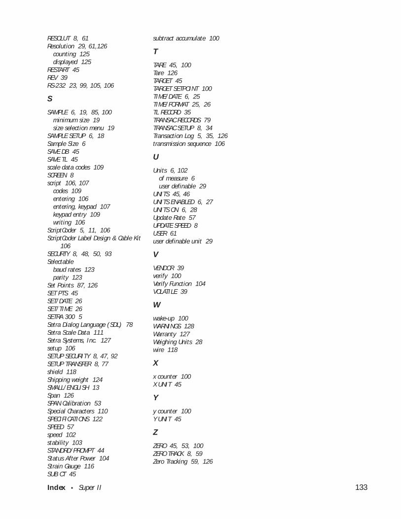
Index • Super II 133
RESOLUT 8, 61Resolution 29, 61,126
counting 125displayed 125
RESTART 45REV 39RS-232 23, 99, 105, 106
S
SAMPLE 6, 19, 85, 100minimum size 19size selection menu 19
SAMPLE SETUP 6, 18Sample Size 6SAVE DB 45SAVE TL 45scale data codes 109SCREEN 8script 106, 107
codes 109entering 106entering, keypad 107keypad entry 109writing 106
ScriptCoder 5, 11, 106ScriptCoder Label Design & Cable Kit
106SECURTY 8, 48, 50, 93Selectable
baud rates 123parity 123
Set Points 87, 126SET PTS 45SET/DATE 26SET/TIME 26SETRA 300 5Setra Dialog Language (SDL) 78Setra Scale Data 111Setra Systems, Inc. 127setup 106SETUP SECURITY 8, 47, 92SETUP TRANSFER 8, 77shield 118Shipping weight 124SMALL/ENGLISH 13Span 126SPAN Calibration 53Special Characters 110SPECIFICATIONS 122SPEED 57speed 102stability 103STANDRD/PROMPT 44Status After Power 104Strain Gauge 116SUB CT 45
subtract accumulate 100
T
TARE 45, 100Tare 126TARGET 45TARGET SETPOINT 100TIME/DATE 6, 25TIME/FORMAT 25, 26TL RECORD 35TRANSAC RECORDS 79TRANSAC SETUP 8, 34Transaction Log 5, 35, 126transmission sequence 106
U
Units 6, 102of measure 6user definable 29
UNITS 45, 46UNITS ENABLED 6, 27UNITS ON 6, 28Update Rate 57UPDATE SPEED 8USER 61user definable unit 29
V
VENDOR 39verify 100Verify Function 104VOLATILE 39
W
wake-up 100WARNINGS 128Warranty 127Weighing Units 28wire 118
X
x counter 100X UNIT 45
Y
y counter 100Y UNIT 45
Z
ZERO 45, 53, 100ZERO TRACK 8, 59Zero Tracking 59, 126
Related Documents


![IBRAHIM v. U.S. DHS et al, No. 16-cv-01719 [D. DC] EB-5 Complaint Filed August 24, 2016](https://static.cupdf.com/doc/110x72/5a6d14557f8b9ab8418b533b/ibrahim-v-us-dhs-et-al-no-16-cv-01719-d-dc-eb-5-complaint-filed-august.jpg)


