FMK20-30HFUS-eng-IUS111610 | IMUS-FMK20-30HFUS | Version 1.0 CA US Accessories for Sunny Boy 2000HF-US/2500HF-US/3000HF-US Flush‑Mount Kit Installation Guide

Welcome message from author
This document is posted to help you gain knowledge. Please leave a comment to let me know what you think about it! Share it to your friends and learn new things together.
Transcript

FMK20-30HFUS-eng-IUS111610 | IMUS-FMK20-30HFUS | Version 1.0 CA US
Accessories for Sunny Boy 2000HF-US/2500HF-US/3000HF-USFlush‑Mount KitInstallation Guide


SMA America, LLC Legal restrictions
Installation Guide FMK20-30HFUS-eng-IUS111610 3
Copyright © 2011 SMA America, LLC. All rights reserved.No part of this document may be reproduced, stored in a retrieval system, or transmitted, in any form or by any means, electronic, mechanical, photographic, magnetic or otherwise, without the prior written permission of SMA America, LLC.Neither SMA America, LLC nor SMA Solar Technology Canada Inc. makes representations, express or implied, with respect to this documentation or any of the equipment and/or software it may describe, including (with no limitation) any implied warranties of utility, merchantability, or fitness for any particular purpose. All such warranties are expressly disclaimed. Neither SMA America, LLC nor its distributors or dealers nor SMA Solar Technology Canada Inc. nor its distributors or dealers shall be liable for any indirect, incidental, or consequential damages under any circumstances.(The exclusion of implied warranties may not apply in all cases under some statutes, and thus the above exclusion may not apply.)Specifications are subject to change without notice. Every attempt has been made to make this document complete, accurate and up-to-date. Readers are cautioned, however, that SMA America, LLC and SMA Solar Technology Canada Inc. reserve the right to make changes without notice and shall not be responsible for any damages, including indirect, incidental or consequential damages, caused by reliance on the material presented, including, but not limited to, omissions, typographical errors, arithmetical errors or listing errors in the content material.All trademarks are recognized even if these are not marked separately. Missing designations do not mean that a product or brand is not a registered trademark.The Bluetooth® word mark and logos are registered trademarks owned by Bluetooth SIG, Inc. and any use of such marks by SMA America, LLC and SMA Solar Technology Canada Inc. is under license.
SMA America, LLC3801 N. Havana Street
Denver, CO 80239 U.S.A.
SMA Solar Technology Canada Inc.2425 Matheson Blvd. E
8th FloorMississauga, ON L4W 5K5
Canada
Important Safety Instructions SMA America, LLC
4 FMK20-30HFUS-eng-IUS111610 Installation Guide
IMPORTANT SAFETY INSTRUCTIONSSAVE THESE INSTRUCTIONSThis manual contains important instructions for the following products:
• Flush‑Mount KitThis manual must be followed during installation and maintenance.
The product is designed and tested according to international safety requirements, but as with all electrical and electronic equipment, certain precautions must be observed when installing and/or operating the product. To reduce the risk of personal injury and to ensure the safe installation and operation of the product, you must carefully read and follow all instructions, cautions and warnings in this manual.
Warnings in this documentA warning describes a hazard to equipment or personnel. It calls attention to a procedure or practice, which, if not correctly performed or adhered to, could result in damage to or destruction of part or all of the SMA equipment and/or other equipment connected to the SMA equipment or personal injury.
DANGER indicates a hazardous situation which, if not avoided, will result in death or serious injury.
WARNING indicates a hazardous situation which, if not avoided, could result in death or serious injury.
CAUTION indicates a hazardous situation which, if not avoided, could result in minor or moderate injury.
NOTICE is used to address practices not related to personal injury.
SMA America, LLC Important Safety Instructions
Installation Guide FMK20-30HFUS-eng-IUS111610 5
Other Symbols in this documentIn addition to the safety and hazard symbols described on the previous pages, the following symbol is also used in this manual:
General Warnings
Information
This symbol accompanies notes that call attention to supplementary information that you must know and use to ensure optimal operation of the system.
General WarningsAll electrical installations must be done in accordance with the local and National Electrical Code® ANSI/NFPA 70 or the Canadian Electrical Code® CSA C22.1. This document does not and is not intended to replace any local, state, provincial, federal or national laws, regulation or codes applicable to the installation and use of the product, including without limitation applicable electrical safety codes. All installations must conform with the laws, regulations, codes and standards applicable in the jurisdiction of installation. SMA assumes no responsibility for the compliance or noncompliance with such laws or codes in connection with the installation of the product. Before installing or using the product, read all of the instructions, cautions, and warnings in this manual.

SMA America, LLC
6 FMK20-30HFUS-eng-IUS111610 Installation Guide
SMA America, LLC Inhaltsverzeichnis
Installation Guide FMK20-30HFUS-eng-IUS111610 7
Table of Contents1 Information on this Manual. . . . . . . . . . . . . . . . . . . . . . . . . 91.1 Validity . . . . . . . . . . . . . . . . . . . . . . . . . . . . . . . . . . . . . . . . . . . . 91.2 Target Group . . . . . . . . . . . . . . . . . . . . . . . . . . . . . . . . . . . . . . . 91.3 Additional Information . . . . . . . . . . . . . . . . . . . . . . . . . . . . . . . . 91.4 Nomenclature . . . . . . . . . . . . . . . . . . . . . . . . . . . . . . . . . . . . . . . 92 Safety . . . . . . . . . . . . . . . . . . . . . . . . . . . . . . . . . . . . . . . . . 102.1 Appropriate Usage. . . . . . . . . . . . . . . . . . . . . . . . . . . . . . . . . . 102.2 Safety Instructions . . . . . . . . . . . . . . . . . . . . . . . . . . . . . . . . . . . 103 Flush‑Mount Kit. . . . . . . . . . . . . . . . . . . . . . . . . . . . . . . . . . 123.1 Scope of Delivery . . . . . . . . . . . . . . . . . . . . . . . . . . . . . . . . . . . 124 Installation . . . . . . . . . . . . . . . . . . . . . . . . . . . . . . . . . . . . . 134.1 Selecting the Mounting Location. . . . . . . . . . . . . . . . . . . . . . . . 134.2 Dimensions . . . . . . . . . . . . . . . . . . . . . . . . . . . . . . . . . . . . . . . . 144.3 Installing the Flush‑Mount Kit. . . . . . . . . . . . . . . . . . . . . . . . . . . 154.4 Mounting the Installation Tray . . . . . . . . . . . . . . . . . . . . . . . . . 164.5 Attaching the Wall Mounting Bracket. . . . . . . . . . . . . . . . . . . . 174.6 Mounting the Inverter . . . . . . . . . . . . . . . . . . . . . . . . . . . . . . . . 184.7 Installing the Cable Ducts . . . . . . . . . . . . . . . . . . . . . . . . . . . . . 204.7.1 Connecting the AC Cable and DC Cable to SMA DC‑Disconnect . . . . . . . . 214.7.2 Affixing the Label with Technical Data . . . . . . . . . . . . . . . . . . . . . . . . . . . . . 224.8 Mounting the Cover Frame. . . . . . . . . . . . . . . . . . . . . . . . . . . . 245 Disassembly . . . . . . . . . . . . . . . . . . . . . . . . . . . . . . . . . . . . 255.1 Disassembling the Cover Frame . . . . . . . . . . . . . . . . . . . . . . . . 255.2 Disassembling the Inverter . . . . . . . . . . . . . . . . . . . . . . . . . . . . 265.3 Disassembling the Installation Tray . . . . . . . . . . . . . . . . . . . . . . 26
Inhaltsverzeichnis SMA America, LLC
8 FMK20-30HFUS-eng-IUS111610 Installation Guide
6 Technical Data . . . . . . . . . . . . . . . . . . . . . . . . . . . . . . . . . . 277 Contact . . . . . . . . . . . . . . . . . . . . . . . . . . . . . . . . . . . . . . . . 28
SMA America, LLC Information on this Manual
Installation Guide FMK20-30HFUS-eng-IUS111610 9
1 Information on this Manual1.1 ValidityThese instructions are valid for the Flush‑Mount Kit for the following inverters:
• Sunny Boy 2000HF-US (SB 2000HFUS‑30)• Sunny Boy 2500HF-US (SB 2500HFUS‑30)• Sunny Boy 3000HF-US (SB 3000HFUS‑30)
1.2 Target GroupThis manual is for qualified personnel. Qualified personnel received training and have demonstrated skills and knowledge in the construction and operation of this device. Qualified personnel are trained to deal with the dangers and hazards involved in installing electric devices.
1.3 Additional InformationDetailed information on the installation and commissioning of the inverter can be found in the installation guide for the inverter.
1.4 NomenclatureIn this document SMA America Production, LLC is referred to in the following as SMA.In this document, the inverters Sunny Boy 2000HF-US, Sunny Boy 2500HF-US, and Sunny Boy 3000HF-US are hereafter referred to as Sunny Boy.
Safety SMA America, LLC
10 FMK20-30HFUS-eng-IUS111610 Installation Guide
2 Safety2.1 Appropriate UsageThe Flush‑Mount Kit is an accessory for the inverters SB2000HF-US, SB2500HF-US, and SB3000HF-US. The Flush‑Mount Kit enables the inverter to be fixed between the posts of lightweight walls. An installation depth of at least 39⁄16 in. (90 mm) is needed for the installation.The Flush‑Mount Kit must only be used in accordance with these instructions. Any other application can lead to personal injuries or damage to equipment.
2.2 Safety Instructions
Risk of fatal injury by electric shock when working on this inverter. Any work on the inverter must only be carried out in the absence of voltage and in compliance with the five safety rules.
• Disconnect.• Ensure that the device cannot be reconnected.• Ensure that no voltage is present in the system.• Ground and short-circuit.• Cover or shield any adjacent live parts.
Risk of fatal injury by proceeding incorrectly when working on this inverter.• All work on the inverter must only be carried out as described in the installation guide.• All safety instructions in the installation guide of the inverter and these instructions must be
observed.• All work on the inverter may only be performed by qualified personnel.
Risk of crushing due to falling individual parts of the Flush‑Mount Kit. • The weight of the individual parts must be a maximum of 7 lbs. (3 kg) during mounting.• Always use both hands to lift individual parts of the Flush‑Mount Kit.
SMA America, LLC Safety
Installation Guide FMK20-30HFUS-eng-IUS111610 11
Risk of injury due to sharp corners and edges on individual parts of the Flush‑Mount Kit. • Only unpack and assemble the Flush‑Mount Kit while wearing suitable safety clothing and
gloves.
Flush‑Mount Kit SMA America, LLC
12 FMK20-30HFUS-eng-IUS111610 Installation Guide
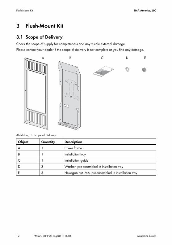
3 Flush‑Mount Kit3.1 Scope of DeliveryCheck the scope of supply for completeness and any visible external damage.Please contact your dealer if the scope of delivery is not complete or you find any damage.
Abbildung 1: Scope of Delivery
Object Quantity DescriptionA 1 Cover frameB 1 Installation trayC 1 Installation guideD 3 Washer, pre-assembled in installation trayE 3 Hexagon nut, M6, pre-assembled in installation tray
SMA America, LLC Installation
Installation Guide FMK20-30HFUS-eng-IUS111610 13
4 Installation4.1 Selecting the Mounting Location
• Select a mounting location in which the inverter can be easily accessed for service work.• Select a mounting location which has enough space for the air to circulate freely.• Select a mounting location with an ambient temperature less than +112 °F (+45 °C).• Mount the Flush‑Mount Kit and inverter in an area protected against direct sunlight and
moisture.• Select a mounting wall that can bear the weight of the Flush‑Mount Kit and the inverter.• Minimum distance between the posts 1 ft. 2 in. (355 mm).• Select a vertical mounting location.• Mount the Flush‑Mount Kit with the connection area facing downwards.
Danger to life due to fire or explosion.• Do not mount the Flush‑Mount Kit on combustible materials.• Do not mount the Flush‑Mount Kit in areas in which highly inflammable materials are stored.• Do not mount the Flush‑Mount Kit in potentially explosive atmospheres.
Noise pollutionThe inverter can cause audible vibrations in operation. Lightweight walls can increase these vibrations. This can be perceived as an annoyance in living areas. Do not mount in lightweight walls in living areas.
Installation SMA America, LLC
14 FMK20-30HFUS-eng-IUS111610 Installation Guide
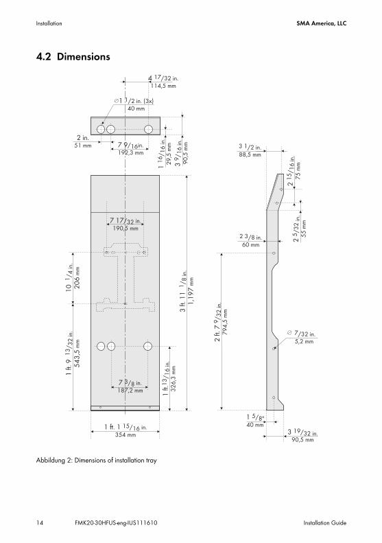
4.2 Dimensions
Abbildung 2: Dimensions of installation tray
1 ft. 1 15/16354 mm
in.
7 3/8187,2 mm
in.
1 ft.1
3/ 1
6 in
.3
26
,3 m
m
3 ft.
11
1,1
97
1/ 8
in.
mm
11
6/ 1
6 in
.2
9,5
mm
1 5/8"40 mm
2 ft.
79
/ 32
in.
79
4,5
mm
2 in.51 mm
7 17/32190,5 mm
in.
10 20
61/ 4
in.
mm
1 ft.
95
43
,513
/ 32
in.
mm
39
/ 16
in.
90
,5 m
m
4 /32 in.114,5 mm
7 9/16192,3 mm
in.
1 1/2 in. (3x)40 mm
3 1/2 in.88,5 mm
21
5/ 1
6 in
.7
5 m
m2
5/3
2in
.5
5 m
m
2 3/8 in.60 mm
3 19/32 in.90,5 mm
7/32 in.5,2 mm
1 ft. 1 15/16354 mm
in.
7 3/8187,2 mm
in.
1 ft.1
3/ 1
6 in
.3
26
,3 m
m
3 ft.
11
1,1
97
1/ 8
in.
mm
11
6/ 1
6 in
.2
9,5
mm
1 5/8"40 mm
2 ft.
79
/ 32
in.
79
4,5
mm
2 in.51 mm
7 17/32190,5 mm
in.
10 20
61/ 4
in.
mm
1 ft.
95
43
,513
/ 32
in.
mm
39
/ 16
in.
90
,5 m
m
4 17/32 in.114,5 mm
7 9/16192,3 mm
in.
1 1/2 in. (3x)40 mm
3 1/2 in.88,5 mm
21
5/ 1
6 in
.7
5 m
m2
5/3
2in
.5
5 m
m
2 3/8 in.60 mm
3 19/32 in.90,5 mm
7/32 in.5,2 mm
SMA America, LLC Installation
Installation Guide FMK20-30HFUS-eng-IUS111610 15
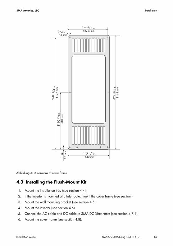
Abbildung 3: Dimensions of cover frame
4.3 Installing the Flush‑Mount Kit1. Mount the installation tray (see section 4.4).2. If the inverter is mounted at a later date, mount the cover frame (see section ).3. Mount the wall mounting bracket (see section 4.5).4. Mount the inverter (see section 4.6).5. Connect the AC cable and DC cable to SMA DC‑Disconnect (see section 4.7.1).6. Mount the cover frame (see section 4.8).
1'-5 3/8in.440 mm
3'-9
3/ 4
in.
11
62
mm
3'-8
3/ 4
in.
11
37
mm
1 in
.2
5 m
m
1'-4 5/8 in.422,5 mm
1'-1
07
/ 8 in
.5
81
mm
3/4 in.17,5 mm
Installation SMA America, LLC
16 FMK20-30HFUS-eng-IUS111610 Installation Guide
4.4 Mounting the Installation TrayAdditional mounting material (not included in the scope of delivery):
• 10 screws with a maximum diameter of 5⁄16 in. (8 mm).• At least 10 washers
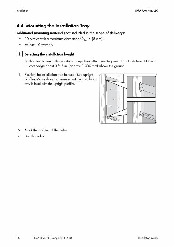
1. Position the installation tray between two upright profiles. While doing so, ensure that the installation tray is level with the upright profiles.
2. Mark the position of the holes.3. Drill the holes.
Selecting the installation heightSo that the display of the inverter is at eye-level after mounting, mount the Flush‑Mount Kit with its lower edge about 3 ft. 3 in. (approx. 1 000 mm) above the ground.
SMA America, LLC Installation
Installation Guide FMK20-30HFUS-eng-IUS111610 17
4. Secure the installation tray to the upright profiles with at least six screws and washers.
4.5 Attaching the Wall Mounting Bracket
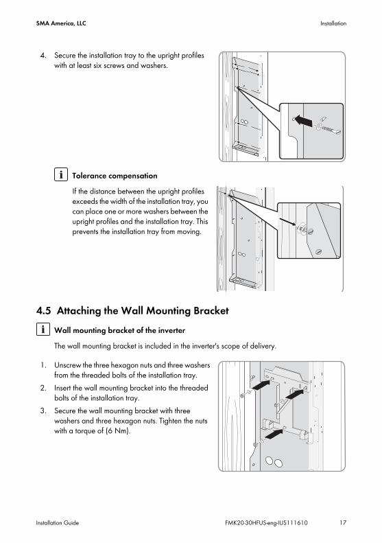
1. Unscrew the three hexagon nuts and three washers from the threaded bolts of the installation tray.
2. Insert the wall mounting bracket into the threaded bolts of the installation tray.
3. Secure the wall mounting bracket with three washers and three hexagon nuts. Tighten the nuts with a torque of (6 Nm).
Tolerance compensationIf the distance between the upright profiles exceeds the width of the installation tray, you can place one or more washers between the upright profiles and the installation tray. This prevents the installation tray from moving.
Wall mounting bracket of the inverterThe wall mounting bracket is included in the inverter's scope of delivery.
Installation SMA America, LLC
18 FMK20-30HFUS-eng-IUS111610 Installation Guide
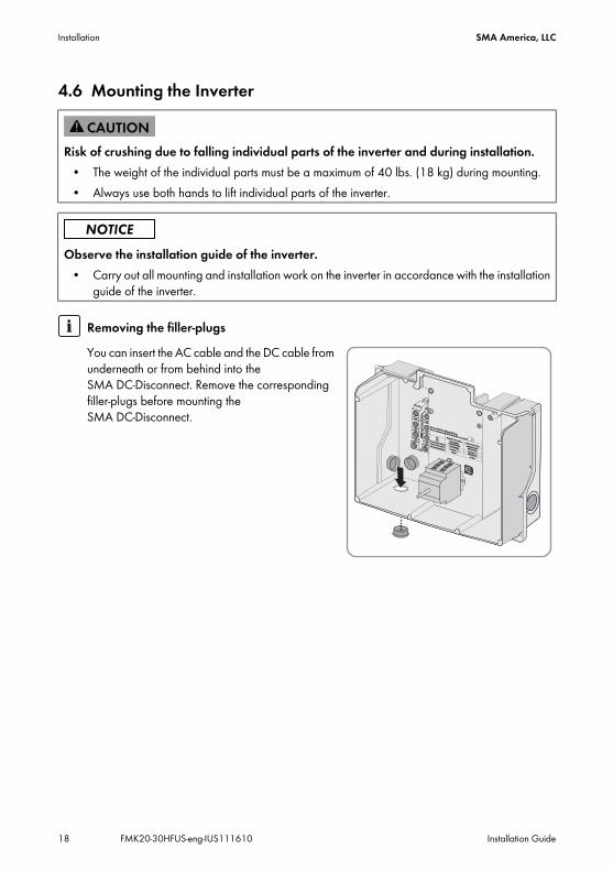
4.6 Mounting the Inverter
Risk of crushing due to falling individual parts of the inverter and during installation. • The weight of the individual parts must be a maximum of 40 lbs. (18 kg) during mounting.• Always use both hands to lift individual parts of the inverter.
Observe the installation guide of the inverter.• Carry out all mounting and installation work on the inverter in accordance with the installation
guide of the inverter.
Removing the filler-plugsYou can insert the AC cable and the DC cable from underneath or from behind into the SMA DC‑Disconnect. Remove the corresponding filler-plugs before mounting the SMA DC‑Disconnect.
One and Two String Wiring
(for more strings and further information see manual)
One and Two String Wiring
(for more strings and further information see manual)DC +DC +
Negative Grounding
Negative GroundingPositive Grounding
Positive Grounding
DC -DC -
UNGROUNDED
UNGROUNDEDGROUNDED
GROUNDED
GROUNDED
GROUNDED
UNGROUNDED
UNGROUNDED
GROUNDED
GROUNDED
GROUNDED
GROUNDED
TerminalTerminal =
~TerminalTerminal =
~
Facing -Facing -
Facing +Facing +
Inverter Wire black (-)
Inverter Wire black (-)Inverter Wire red (+)
Inverter Wire red (+)PLUG-IN GROUNDING
PLUG-IN GROUNDING
SMA America, LLC Installation
Installation Guide FMK20-30HFUS-eng-IUS111610 19
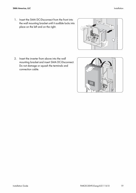
1. Insert the SMA DC‑Disconnect from the front into the wall mounting bracket until it audible locks into place on the left and on the right.
2. Insert the inverter from above into the wall mounting bracket and insert SMA DC‑Disconnect. Do not damage or squash the terminals and connection cable.
One and Two String Wiring
(for more strings and further information see manual)
One and Two String Wiring
(for more strings and further information see manual)DC +DC +
Negative Grounding
Negative GroundingPositive Grounding
Positive Grounding
One and TwoString DC-Wiring
One and TwoString DC-Wiring
DC -DC -
UNGROUNDED
UNGROUNDEDGROUNDED
GROUNDED
GROUNDED
GROUNDED
UNGROUNDED
UNGROUNDED
GROUNDED
GROUNDED
GROUNDED
GROUNDED
TerminalTerminal =
~TerminalTerminal =
~
Facing -Facing -
Facing +Facing +
Inverter Wire black (-)
Inverter Wire black (-)Inverter Wire red (+)
Inverter Wire red (+)PLUG-IN GROUNDING
PLUG-IN GROUNDING
Installation SMA America, LLC
20 FMK20-30HFUS-eng-IUS111610 Installation Guide
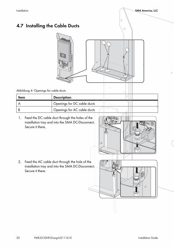
4.7 Installing the Cable Ducts
Abbildung 4: Openings for cable ducts
1. Feed the DC cable duct through the holes of the installation tray and into the SMA DC‑Disconnect. Secure it there.
2. Feed the AC cable duct through the hole of the installation tray and into the SMA DC‑Disconnect. Secure it there.
Item DescriptionA Openings for DC cable ductsB Openings for AC cable ducts
SMA America, LLC Installation
Installation Guide FMK20-30HFUS-eng-IUS111610 21
4.7.1 Connecting the AC Cable and DC Cable to SMA DC‑Disconnect
1. Connect the AC cable and DC cable to the SMA DC‑Disconnect as described in the installation guide of the inverter.
Risk of fatal injury by electric shock when working on this inverter.The inverter works internally with high voltages.
• The connection of SMA DC‑Disconnect may only be carried out by qualified personnel.
Installation SMA America, LLC
22 FMK20-30HFUS-eng-IUS111610 Installation Guide
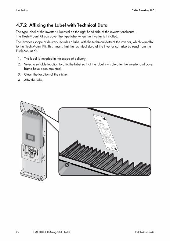
4.7.2 Affixing the Label with Technical DataThe type label of the inverter is located on the right-hand side of the inverter enclosure. The Flush‑Mount Kit can cover the type label when the inverter is installed. The inverter's scope of delivery includes a label with the technical data of the inverter, which you affix to the Flush‑Mount Kit. This means that the technical data of the inverter can also be read from the Flush‑Mount Kit.
1. The label is included in the scope of delivery.2. Select a suitable location to affix the label so that the label is visible after the inverter and cover
frame have been mounted.3. Clean the location of the sticker.4. Affix the label.
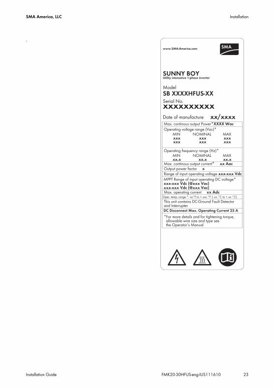
www.SMA-America.com
SUNNY BOY
SB XXXXHFUS-XXxxxxxxxxxx
Model
Serial No.
Date of manufacture xx/xxxx
Max. continous output Power*XXXX Wac
Operating voltage range (Vac)*
MINNOMINAL
MAX
xxx
xxx
xxx
Operating frequency range (Hz)*
MINNOMINAL
MAX
xx.x
xx.x
xx.x
Max. continous output current*xx Aac
Output power factor x
Range of input operating voltage xxx-xxx Vdc
MPPT Range of input operating DC voltage*
xxx-xxx Vdc (@xxx Vac)
xxx-xxx Vdc (@xxx Vac)
Max. operating current xx Adc
This unit contains a Residual Current
Monitor, Isolation Monitor and Interrupteur
ENCLOSUREType 3R (IP54)
*For more details and for tightening torque,
allowable wire size and type see
the Operator‘s Manual
Utility Interactive 1-Phase InverterTested To ComplyWith FCC Standards
FOR HOME AND OFFICE USE
Utility interactive 1-phase inverter
xxx
xxx
xxx
www.SMA-America.com
SUNNY BOY
SB XXXXHFUS-XXxxxxxxxxxx
Model
Serial No.
Date of manufacture xx/xxxx
Max. continous output Power*XXXX Wac
Operating voltage range (Vac)*
MINNOMINAL
MAX
xxx
xxx
xxx
Operating frequency range (Hz)*
MINNOMINAL
MAX
xx.x
xx.x
xx.x
Max. continous output current* xx Aac
Output power factor x
Range of input operating voltage xxx-xxx Vdc
MPPT Range of input operating DC voltage*
xxx-xxx Vdc (@xxx Vac)
xxx-xxx Vdc (@xxx Vac)
Max. operating current xx Adc
This unit contains a Residual Current
Monitor, Isolation Monitor and Interrupteur
ENCLOSURE Type 3R (IP54)
*For more details and for tightening torque,
allowable wire size and type see
the Operator‘s Manual
Utility Interactive 1-Phase InverterTested To ComplyWith FCC Standards
FOR HOME AND OFFICE USE
Utility interactive 1-phase inverter
xxx
xxx
xxx
SMA America, LLC Installation
Installation Guide FMK20-30HFUS-eng-IUS111610 23
.www.SMA-America.com
SUNNY BOY
SB XXXXHFUS-XX
xxxxxxxxxx
Model
Serial No.
Date of manufacture xx/xxxxMax. continous output Power*XXXX Wac
Operating voltage range (Vac)*MIN NOMINAL MAXxxx xxx xxx
Operating frequency range (Hz)*MIN NOMINAL MAXxx.x xx.x xx.x
Max. continous output current* xx Aac
Output power factor x
Range of input operating voltage xxx-xxx Vdc
MPPT Range of input operating DC voltage*xxx-xxx Vdc (@xxx Vac)xxx-xxx Vdc (@xxx Vac)
Max. operating current xx Adc
This unit contains DC-Ground Fault Detectorand InterrupterDC Disconnect Max. Operating Current 25 A
*For more details and for tightening torque,allowable wire size and type seethe Operator‘s Manual
Utility interactive 1-phase inverter
xxx xxx xxx
Oper, temp, range *- xx°F to + xxx °F (- xx °C to + xx °C)
Installation SMA America, LLC
24 FMK20-30HFUS-eng-IUS111610 Installation Guide
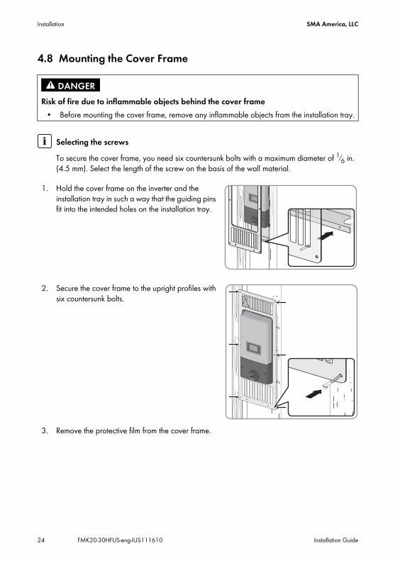
4.8 Mounting the Cover Frame
1. Hold the cover frame on the inverter and the installation tray in such a way that the guiding pins fit into the intended holes on the installation tray.
2. Secure the cover frame to the upright profiles with six countersunk bolts.
3. Remove the protective film from the cover frame.
Risk of fire due to inflammable objects behind the cover frame• Before mounting the cover frame, remove any inflammable objects from the installation tray.
Selecting the screwsTo secure the cover frame, you need six countersunk bolts with a maximum diameter of 1⁄6 in. (4.5 mm). Select the length of the screw on the basis of the wall material.
SMA America, LLC Disassembly
Installation Guide FMK20-30HFUS-eng-IUS111610 25
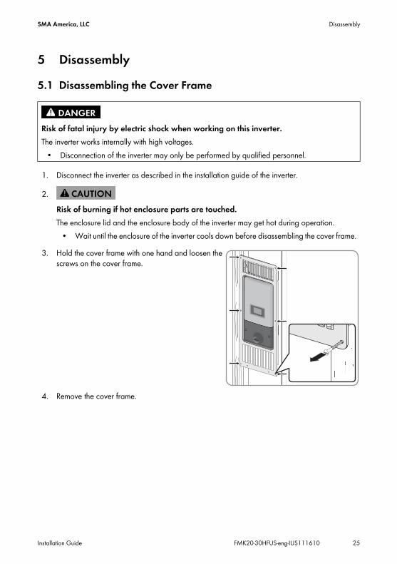
5 Disassembly5.1 Disassembling the Cover Frame
1. Disconnect the inverter as described in the installation guide of the inverter.
3. Hold the cover frame with one hand and loosen the screws on the cover frame.
4. Remove the cover frame.
Risk of fatal injury by electric shock when working on this inverter.The inverter works internally with high voltages.
• Disconnection of the inverter may only be performed by qualified personnel.
2.Risk of burning if hot enclosure parts are touched.The enclosure lid and the enclosure body of the inverter may get hot during operation.
• Wait until the enclosure of the inverter cools down before disassembling the cover frame.
Disassembly SMA America, LLC
26 FMK20-30HFUS-eng-IUS111610 Installation Guide
5.2 Disassembling the Inverter
1. Disassemble the inverter as described in the installation guide of the inverter.2. Disassemble the DC‑Disconnect as described in the installation guide of the inverter.
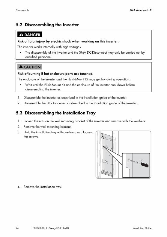
5.3 Disassembling the Installation Tray1. Loosen the nuts on the wall mounting bracket of the inverter and remove with the washers.2. Remove the wall mounting bracket.3. Hold the installation tray with one hand and loosen
the screws.
4. Remove the installation tray.
Risk of fatal injury by electric shock when working on this inverter.The inverter works internally with high voltages.
• The disassembly of the inverter and the SMA DC‑Disconnect may only be carried out by qualified personnel.
Risk of burning if hot enclosure parts are touched.The enclosure of the inverter and the Flush‑Mount Kit may get hot during operation.
• Wait until the Flush‑Mount Kit and the enclosure of the inverter cool down before disassembling the inverter.
SMA America, LLC Technical Data
Installation Guide FMK20-30HFUS-eng-IUS111610 27
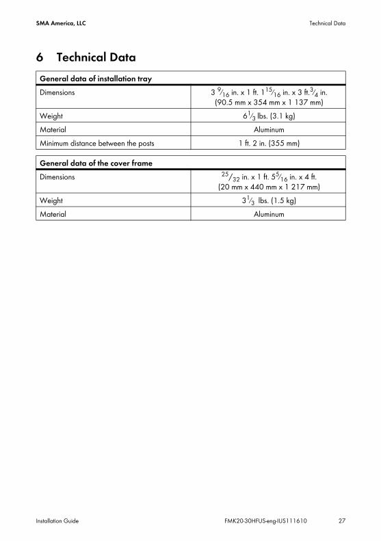
6 Technical DataGeneral data of installation trayDimensions 3 9⁄16 in. x 1 ft. 115⁄16 in. x 3 ft.3⁄4 in.
(90.5 mm x 354 mm x 1 137 mm)Weight 61⁄3 lbs. (3.1 kg)Material AluminumMinimum distance between the posts 1 ft. 2 in. (355 mm)
General data of the cover frameDimensions 25/32 in. x 1 ft. 55⁄16 in. x 4 ft.
(20 mm x 440 mm x 1 217 mm)Weight 31⁄3 lbs. (1.5 kg)Material Aluminum

Contact SMA America, LLC
28 FMK20-30HFUS-eng-IUS111610 Installation Guide
7 ContactShould you experience any technical problems with our products, contact the SMA Serviceline. We require the following information in order to provide you with the necessary assistance:
• Inverter type• Type and number of modules connected• Way of communication• Sunny Boy failure or warning number• Display message of the Sunny Boy
SMA America, LLC6020 West Oaks Blvd, Ste 300Rocklin, CA 95765Tel. +1 916 625 0870Tel. +1 877-MY SMA TECHTel. +1 877 697 6283 (Toll free, available for USA, Canada and Puerto Rico)Fax +1 916 625 [email protected]
SMA Solar Technology Canada Inc.2425 Matheson Blvd E, 8th FloorMississauga, ON L4W 5K5, CanadaTel. +1 877 506 1756 (Toll free, available for Canada)[email protected]


Related Documents