NM OIL CONSERVATION ARTISIA BtSTfttCT Form 3160-5 (August 2007) OCD UNITED STATES DEPARTMENT OF THE INTERIOR BUREAU OF LAND MANAGEMENT SUNDRY NOTICES AND REPORTS ON WELLS RECEIVED Do not use this form for proposals to drill or to re-enter an abandoned well. Use form 3160-3 (APD) for such proposals. FORM APPROVED OMBNO. 1004-0135 Expires: July 31, 2010 5. Lease Serial No. NMNM04557 6. If Indian, Allottee or Tribe Name SUBMIT IN TRIPLICATE - Other instructions on reverse side. 7. If Unit or CA/Agrcemcnt, Name and/or No. 891000326X 1. Type of Well g] Oil Well • Gas Well • Other 8. Well Name and No. BIG EDDY UNIT DI4 269H 2. Name of Operator BOPCO LP Contact: LESLIE BARNES E-Mail: [email protected] 9. API Well No. 30-015-42638-00-X1 3a. Address P O BOX 2760 MIDLAND, TX 79702 3b. Phone No. (include area code) Ph: 432-221-7341 10. Field and Pool, or Exploratory WILLIAMS SINK 4. Location of Well (Footage. Sec., T., R., M., or Survey Description) Sec 5 T20S R31E Lot 2 358FNL 2058FEL 32.362762 N Lat, 103.532109 W Lon 11. County or Parish, and State EDDY COUNTY, NM 12. CHECK APPROPRIATE BOX(ES) TO INDICATE NATURE OF NOTICE, REPORT, OR OTHER DATA TYPE OF SUBMISSION TYPE OF ACTION g) Notice of Intent • Subsequent Report • Final Abandonment Notice • Acidize • Deepen • Production (Start/Resume) • Water Shut-Off g) Notice of Intent • Subsequent Report • Final Abandonment Notice • Alter Casing • Casing Repair • Change Plans • Fracture Treat • New Construction • Plug and Abandon • Reclamation ,; • • Recomplete • Temporarily Abandpn^gjteu : V . • Well Integrity SP" B,Qther "' '"Change to Original A • Convert to Injection • Plug Back • Water Disposal -.fil 13. Describe Proposed or Completed Operation (clearly state all pertinent details, including estimated starting date of any proposed work and app7oxima.te;duration thereof. If the proposal is to deepen dircctionally or recomplete horizontally, give subsurface locations and measured and true vertical depths of aH pfirlincnt markers and zones. Attach the Bond under which the work will be performed or provide the Bond No. on file with BLM/BIA. Required subsequent reports shall be filed within 30 days following completion ofthe involved operations. If the operation results in a multiple completion or recompletion in a new interval, a Form 3160-4 shall be filed once testing has been completed. Final Abandonment Notices shall bc filed only after all requirements, including rcclamation^h^vc^cfi^^ej^pietjd^S^^Jhc operator has detennined that the site is ready forfinalinspection.) BOPCO, LP respectfully requests to alter the directional plan and the production casino 5-1/2?, 17.00 ppf, HCP-110, BTC casing. The new directional plan will change the(ai from a 2nd Bone Spring sand to a 1st Bone Spring Sand. A DV tool will be placed at +/- 5,000? and the 5-1/2? casing string will be cemented in two stages. Top of cement of stage 2 will be placed at least 50? above the top of the Capitan Reef at +/- 2,898?. The updated directional plan is attached. Casing safety factors are as follows: 5-1/2?, 17.00 ppf, HCP-110, BTC - Collapse ? 2.00, Burst ? 2.29, Tension ? 4.46 Updated cement volumes and slurries are in the attached table. uding reclamation, havciccivsejiMleted/SsaThc op SEE ATTACHED r» - MSmONS OF ArtfOVAL 14. I hereby certify that the foregoing is true and correct. Electronic Submission #279116 verified For BOPCO LP, si int Committed to AFMSS for processing by JENNIFER N m K (Printed/Typed) JEREMY BRADEN by the BLM Well Information System hRLSegt to the Carlsbad V/- MASON on 11/19/2014/(15JAM0093SE) Title DRILLING ENGINEER, Signature (Electronic Submission) ATPRQlEG THIS SPACE FOR FEDERAL OR STATE _App_rovcd_By_ Conditions of approval, if any, arc attached. Approval of this notice does not warrant or certify that the applicant holds legal or equitable title to those rights in the subject lease which would entitle the applicant to conduct operations thereon. Title 18 U.S.C. Section 1001 and Title 43 U.S.C. Section 1212, make it a crime for any person knowingly and willfully to make'-to'an^department or agency ofthe United States any false, fictitious or fraudulent statements or representations as to any matter within its jurisdiction. ' 'jfjffif BLM REVISED ** BLM REVISED ** BLM REVISED ** BLM REVISED ** BLM REVISED

Welcome message from author
This document is posted to help you gain knowledge. Please leave a comment to let me know what you think about it! Share it to your friends and learn new things together.
Transcript
NM OIL CONSERVATION ARTISIA BtSTfttCT
Form 3160-5 (August 2007)
OCD UNITED STATES
DEPARTMENT OF THE INTERIOR BUREAU OF LAND MANAGEMENT
SUNDRY NOTICES AND REPORTS ON WELLS RECEIVED Do not use this form for proposals to drill or to re-enter an
abandoned well. Use form 3160-3 (APD) for such proposals.
FORM APPROVED OMBNO. 1004-0135 Expires: July 31, 2010
5. Lease Serial No. NMNM04557
6. If Indian, Allottee or Tribe Name
SUBMIT IN TRIPLICATE - Other instructions on reverse side. 7. If Unit or CA/Agrcemcnt, Name and/or No. 891000326X
1. Type of Well g] Oil Well • Gas Well • Other
8. Well Name and No. BIG EDDY UNIT DI4 269H
2. Name of Operator BOPCO LP
Contact: LESLIE BARNES E-Mail: [email protected]
9. API Well No. 30-015-42638-00-X1
3a. Address P O BOX 2760 MIDLAND, TX 79702
3b. Phone No. (include area code) Ph: 432-221-7341
10. Field and Pool, or Exploratory WILLIAMS SINK
4. Location of Well (Footage. Sec., T., R., M., or Survey Description)
Sec 5 T20S R31E Lot 2 358FNL 2058FEL 32.362762 N Lat, 103.532109 W Lon
11. County or Parish, and State
EDDY COUNTY, NM
12. CHECK APPROPRIATE BOX(ES) TO INDICATE NATURE OF NOTICE, REPORT, OR OTHER DATA
TYPE OF SUBMISSION TYPE OF ACTION
g) Notice of Intent
• Subsequent Report
• Final Abandonment Notice
• Acidize • Deepen • Production (Start/Resume) • Water Shut-Off g) Notice of Intent
• Subsequent Report
• Final Abandonment Notice
• Alter Casing
• Casing Repair
• Change Plans
• Fracture Treat
• New Construction
• Plug and Abandon
• Reclamation ,; •
• Recomplete
• Temporarily Abandpn^gjteu
: V . • Well Integrity SP"
B,Qther "' '"Change to Original A
• Convert to Injection • Plug Back • Water Disposal - . f i l
13. Describe Proposed or Completed Operation (clearly state all pertinent details, including estimated starting date of any proposed work and app7oxima.te;duration thereof. If the proposal is to deepen dircctionally or recomplete horizontally, give subsurface locations and measured and true vertical depths of aH pfirlincnt markers and zones. Attach the Bond under which the work will be performed or provide the Bond No. on file with BLM/BIA. Required subsequent reports shall be filed within 30 days following completion ofthe involved operations. If the operation results in a multiple completion or recompletion in a new interval, a Form 3160-4 shall be filed once testing has been completed. Final Abandonment Notices shall bc filed only after all requirements, including rcclamation^h^vc^cfi^^ej^pietjd^S^^Jhc operator has detennined that the site is ready for final inspection.)
BOPCO, LP respectfully requests to alter the directional plan and the production casino 5-1/2?, 17.00 ppf, HCP-110, BTC casing. The new directional plan will change the(ai from a 2nd Bone Spring sand to a 1st Bone Spring Sand. A DV tool will be placed at +/- 5,000? and the 5-1/2? casing string will be cemented in two stages. Top of cement of stage 2 will be placed at least 50? above the top of the Capitan Reef at +/- 2,898?. The updated directional plan is attached. Casing safety factors are as follows:
5-1/2?, 17.00 ppf, HCP-110, BTC - Collapse ? 2.00, Burst ? 2.29, Tension ? 4.46
Updated cement volumes and slurries are in the attached table.
uding reclamation, havciccivsejiMleted/SsaThc op
SEE ATTACHED r » -MSmONS OF ArtfOVAL
14. I hereby certify that the foregoing is true and correct. Electronic Submission #279116 verified
For BOPCO LP, si int Committed to AFMSS for processing by JENNIFER
N m K (Printed/Typed) J E R E M Y B R A D E N
by the BLM Well Information System hRLSegt to the Carlsbad V/-
MASON on 11/19/2014/(15JAM0093SE)
Title DRILLING ENGINEER,
Signature (Electronic Submission) ATPRQlEG THIS SPACE FOR FEDERAL OR STATE
_App_rovcd_By_
Conditions of approval, if any, arc attached. Approval of this notice does not warrant or certify that the applicant holds legal or equitable title to those rights in the subject lease which would entitle the applicant to conduct operations thereon.
Title 18 U.S.C. Section 1001 and Title 43 U.S.C. Section 1212, make it a crime for any person knowingly and willfully to make'-to'an^department or agency ofthe United States any false, fictitious or fraudulent statements or representations as to any matter within its jurisdiction. ' 'jfjffif
BLM REVISED ** BLM REVISED ** BLM REVISED ** BLM REVISED ** BLM REVISED

BOPCO, LP respectfully requests to alter the directional plan and the production casing string to a 5-
1/2", 17.00 ppf, HCP-110, BTC casing. The new directional plan will change the target formation from a
2 n d Bone Spring sand to a 1 s t Bone Spring Sand. A DV tool will be placed at +/- 5,000' and the 5-1/2"
casing string will be cemented in two stages. Top of cement of stage 2 will be placed at least 50' above
the top of the Capitan Reef at +/- 2,89lf. The updated directional plan is attached. Casing safety factors
are as follows: C ^ j O ' f '
5-1/2", 17.00 ppf, HCP-110, BTC - Collapse - 2.00, Burst - 2.29, Tension - 4.46
Updated cement volumes and slurries are in the below table.
INTERVAL AMOU NT SXS
FT of FILL TYPE GAL/SX PPG FT3/SX
PRODUCTION Stage 1 Lead: 5,000'-7,432' 550 2,432 VersaCem +10%
Bentonite + 0.125 pps Poly-E-Flake + 0.5 pps D-Air + 0.1% HR-601
12.8 11.9 2.24
Tail: 7,432'- 14,094' 2,781 6,662 VersaCem + 0.5% LAP-1 + 0.3% CFR-3 + 0.1% FWCA+ 0.125
pps Poly-E-Flake+ 0.5 pps D-Air+ 0.2% HR-
601
5.32 14.5 1.21
DV TOOL AT 5,000' Stage 2 Lead: 2,898'-4,500' 350 1,746 VersaCem + 10%
Bentonite+ 0.125 pps Poly-E-Flake+ 0.5 pps
D-Air
12.67 11.9 2.23
Tail: 4,500'-5,000' 200 500 Halcem "C" Neat 6.34 14.8 ' 1.33

I ocalion: Field:
Facility:
BOPCO, LP Eddy County, NM Slot: Big Eddy Well: Big Eddy Unit DI-4 Wellbore:
No.269H SHL SL 358 FNL, 2058 FEL N0.269H PWB
Location Information Facility Name | Grid East (US ft) | Grid North (US ft) Latitude Lonqitude
Bio Eddy Unit D M 637263.900 585075.100 32 036'27.666"N 103*53'15.274"W Slot 1 Local N (ft) 1 Local E (ft) Grid East (US ft) Grid North (US ft) Latitude Lonqitude
N0.269H SHL 1 295.72 | -460.93 636803.000 585370.800 3 2 " 3 6 ' 3 0 . 6 i r N 103"53'20.647"W Riq on No.269H SHL (KB) to Mud line (At Slot: No.269H SHL) 3491ft Mean Sea Level to Mud line (At Slot: No.269H SHL) Oft Riq on No.269H SHL (KB) to Mean Sea Level 3491ft
Plot reference wellDath is BEU DI-4 No.269H Rev G.O True vertical depths are referenced'to Riq on No.269M SHL (KB) Grid System: NAD27 / TM New Mexico SP. Eastern Zone (3001). US feet Measured depths are referenced to Riq on No.269H SHL (KB) North Reference: Grid north-Riq on No.269H SHL (K8) to Mean Sea Level: 3491 feet Scale: True distance Mean Sea Level to Mud tine (At Slot: No.269H SHL): 0 feet Depths are in feet Coordinates are in feel referenced to Slot Created by: janotho on 11/12/2014
BGGM (1945.0 to 2016.0) Dip: 60.40' Field: 48428.2 nT Magnetic North rs 7.52 degrees East of True North (at 11/4/2014)
Grid North is 0.24 degrees East of True North To correct azimuth from True lo Grid subtract 0.24 degrees To correct azimuth from Magnetic to Grid add 7.28 degrees
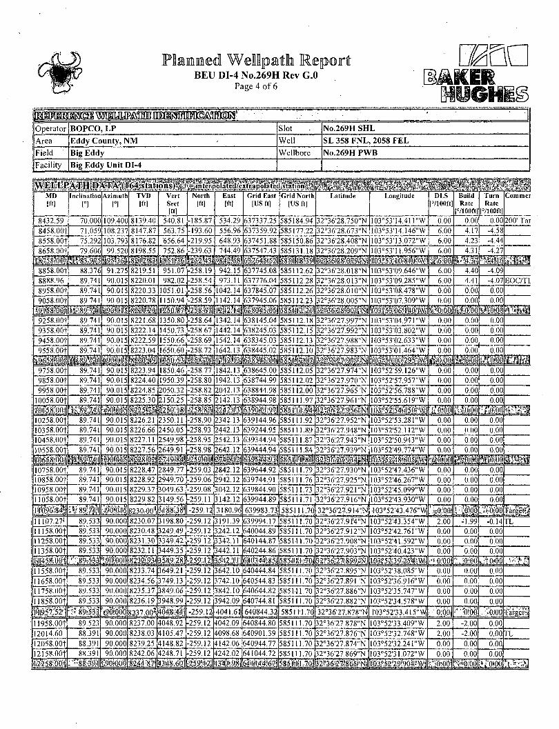
Well Profile Data Desiqn Comment MD (tt) I n c f ) Azn TVD (tt) Local N (ft) Local E (ft) DLS (7100ftt VS (ft)
Tie On 658.00 0.180 47.670 658.00 1.76 1.41 0.54 1.35 End of Drop 676.00 0.000 109.400 676.00 1.78 1.43 1.00 1.37
KOP 7532.59 0.000 109.400 7532.59 1.78 1.43 0.00 1.37 70' Curve 8232.59 70.000 109.400 8070.99 -123.45 357.02 10.00 361.35
200' Tanqenl 8432.59 70.000 109.400 8139.40 -185.87 534.29 0.00 540.81 EOC/TL 8888.96 89.741 90.015 8220.01 -258.54 973.11 6.00 982.02 Tarqel A 11096.84 89.741 90.015 8230.00 •259.12 3180.96 0.00 3188.38
TL 11107.27 89.533 90.000 8230.07 | -259.12 3191.39 2.00 3198.80 Target A.1 11957.52 89.533 90.000 8237.00 -259.12 4041.61 0.00 4048.44
TL 12014.60 88.391 90.000 8238.03 •259.12 4098.68 2.00 4105.47 Tarqet B 12796.96 88.391 90.000 8260.00 -259.12 4880.73 0.00 4886.98
TL 12825.50 87.820 90.000 8260.94 -259.12 4909.25 2.00 4915.48 No. 269H PBHL U904.15 87.820 90.000 8340.00 -259.12 6986.40 0.00 6991.20
BEU NQ.269H PBHL Rev-2
Targets oCBl N (11) I Local E (fl) Grid East (US ft)
32-3ff2?.a78"N
3;'36'27.751-f-
103'5i'J3.476-W io3'52,33.ai5-yy
103'51 •5B.B31-W
Bottom Hole Location MP (ft) I Inc Q I Az Q ITVO (ft) I Local N (ft) I Local E (ft) I Grid East (US ft) I Grid North (US fl) I
l4904.15l87.B20|90.000|83dQ.OO| -259.12 ! 103-51'58.99 f W
Easting (ft) 2100 2400 2700 3000 3300 3600 3900 4200 4500 4800 5100 5400 6300 6600 6900
Target A TL
Tarpet A.1 Target B TL
No. 269H PBHL
KOP : 0.00° Inc, 7532.59ft MD. 7532.59ft TVD, 1.37ft VS
0.99* 361 ,35UV
i 8139.40ft TVD. 540. . 7 0 oo-inc. » w
7 ° " C T " e ' , 7 „ 0 0 - . n c . B 4 3 2 . 5 S « < * . .
6 U E O t m : 89.74' Inc. 8888.96ft MD, 8220.01ft TVD, 982.02ft VS
^ I n - I ^ V * '
MS -(MO-
7l-W ^
-800 -600 -400 -200 O 200 400 1400 I60O 1BO0 2000 2200 2400 2600 2800 3000 3200 3400 3600 3800 4000 4200 4400 4600 4800 5000
Vertical Section (f!) • Azimuth 92.12'with reference 0.00 N, 0.00 E
5400 5800 5800 6000 6200 6400 7000 7200 7400
BEU DI-4 No.269H Rev G.O Page 1 of 6
AKER
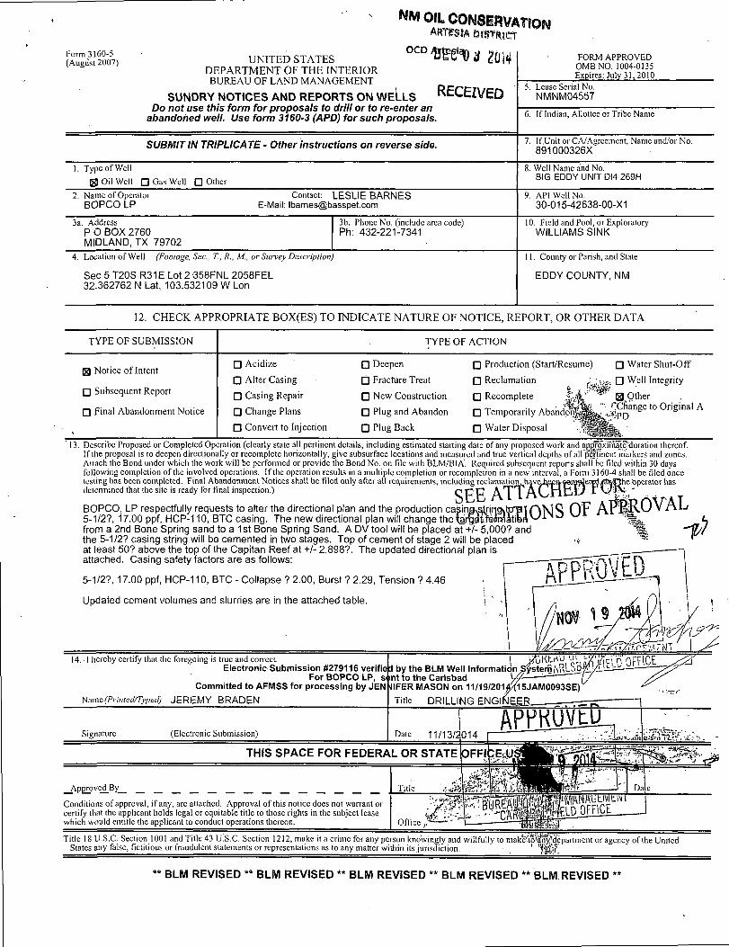
Operator BOPCO, LP Slot No.269H SHL
Area Eddy County, NM Well SL 358 FNL, 2058 F E L
Field Big Eddy Wellbore No.269H PWB
Facility Big Eddy Unit DI-4
INiIMRiiNI Projection System NAD27 / TM New Mexico SP, Eastern Zone (3001), US feet Software System WellArchitect® 4.0.0 North Reference Grid User Janotho Scale 0.999931 Report Generated 11/12/2014 at 2:31:21 PM
Convergence at slot 0.24° East Database/Source file WA_Midland/No.269HJPWB.xml
m :•. •. ,• ... Local coordinates Grid coordinates Geographic coordinates
North|ftl East[ft] Easting[US ft] Northing|US ft| Latitude Longitude
Slot Location 295.72 -460.93 636803.00 585370.80 32°36'30.611"N 103°53'20.647"W
Facility Reference Pt 637263.90 585075.10 32°36'27.666"N 103°53'15.274"W
Field Reference Pt 610823.03 524402.80 32°26'28.262"N 103°58'26.774"W
Calculation method Minimum curvature Rig on No.269H SHL (KB) to Facility Vertical Datum
3491.00ft
Horizontal Reference Pt Slot Rig on No.269H SHL (KB) to Mean Sea Level 3491.00ft
Vertical Reference Pt Rig on No.269H SHL (KB) Rig on No.269H SHL (KB) to Mud Line at Slot (No.269H SHL)
3491.00ft
MD Reference Pt Rig on No.269H SHL (KB) Section Origin N 0.00, E 0.00 ft Field Vertical Reference Mean Sea Level Section Azimuth 92.12°
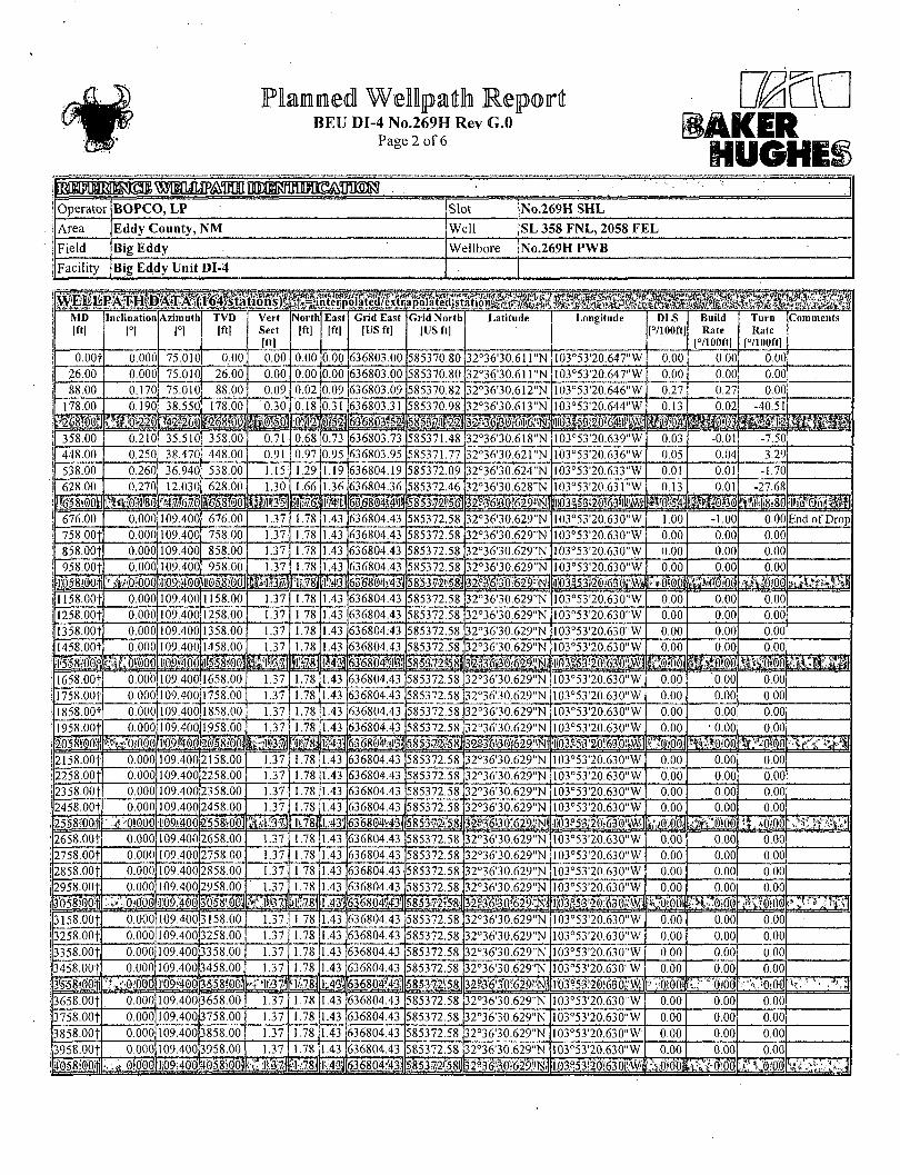
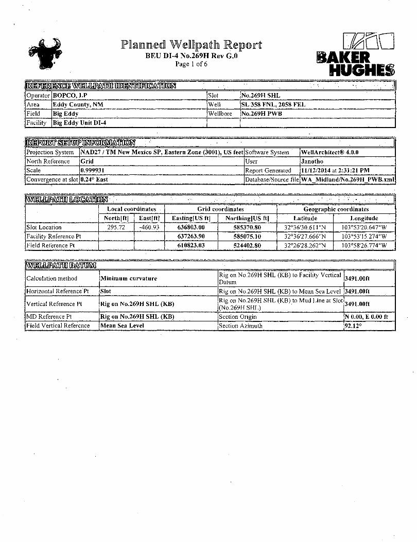
BEU DI-4 No.269H Rev G.O Page 2 of 6
dm lAKER HUGHii
Operator BOPCO, LP Slot No.269H SHL
Area Eddy County, NM Well SL 358 FNL, 2058 FEL
Field Big Eddy Wellbore No.269H PWB
Facility Big Eddy Unit DI-4
•gas ! MD ! I"l
Inclination l°l
Azimuth [°l
TVD [ft]
Vert Sect Iftl
North [ftl
East Iftl
Grid East [US ft |
Grid North |US ft]
Latitude Longitude DLS [°/100ft|
Build Rate
[°/100ftl
Turn Rate
[°/I00ft]
Comments
j o.oot 0.000 75.010 0.00 0.00 0,00 0.00 636803.00 585370.80 32°36'30.611"N I03°53'20.647"W 0.00 0.00 0.00 j 26.00 0.000 75.010 26.00 0.00 0.00 0.00 636803.00 585370.80 32°36'30.6H"N 103°53'20.647"W 0.00 0.00 0.00 i 88.00 0.170 75.010 88.00 0.09 0.02 0.09 636803.09 585370.82 32°36'30.612"N 103°53'20.646"W 0.27 0.27 0.00 | 178.00 0.190 38.550 178.00 0.30 0.18 0.31 636803.31 585370.98 32o36'30.613"N 103°53'20.644"W 0.13 0.02 -40.51
\mm w m m 6368u3*2 » § £ ! mm \ 358.00 0.210 35.510 358.00 0.71 0.68 0.73 636803.73 585371.48 32°36'30.618"N 103°53'20.639"W 0.03 -0.01 -7.50 | 448.00 0.250 38.470 448.00 0.91 0.97 0.95 636803.95 585371.77 32°36'30.621"N I03°53'20.636"W 0.05 0.04 3.29
! 53~8~00 0.260 36.940 •"538.00 1.15 1.29 1.19 636804.19 585372.09 32°36'30.624"N 103°53'20.633"W 0.01 0.01 -1.70 ! 628.00 0.270 12.030 r 628.00 1.30 1.66 1.36 636804.36 585372.46 32°36'30.628"N 103°53'20.631"W 0.13 0.01 -27.68
a t i i i (f658:dd'l 0M llfe'l 6^8Jb4lft 5#53g2l5l mm. ! 676.00 0.000 109.400] 676.00 1.37 1.78 1.43 636804.43 585372.58 32o36'30.629"N I03°53'20.630"W 1.00 -1.00 0.00 End of Drop ! 758.00| 0.000 109.400 758.00 1.37 1.78 1.43 636804.43 585372.58 32°36'30.629"N 103°53'20.630"W 0.00 0.00 0.00 1 858. OOf 0.000 109.400 858.00 1.37 1.78 1.43 636804.43 585372.58 32°36'30.629"N 103°53'20.630"W 0.00 0.00 0.00 ! 958.00f 0.000 109.400 958.00 1.37 1.78 1.43 636804.43 585372.58 32°36'30.629"N 103°53'20.630 , ,W 0.00 0.00 0.00
' f058!00t ;ii09900WI0l8i(i] N#s| <N$, 6MmM 5853»i^8S 32^ i3 l629?y ; iil03iS3^/63'dj% Fitiooi iitsysos. ill58.00t. 0.000 109.400 1158.00 1.37 1.78 1.43 636804.43 585372.58 32°36'30.629"N 103°53'20.630"W 0.00 0.00 0.00
j' 1258.00f 0.000 109.400 1258.00 1.37 1.78 1.43 636804.43 585372.58 32°36'30.629"N 103°53'20.630"W 0.00 0.00 0.00
jl358.00t 0.000 109.400 1358.00 1.37 1.78 1.43 636804.43 585372.58 32°36'30.629"N 103°53'20.630"W 0.00 0.00 0.00 j I458.00| 0.000 109.400 1458.00 1.37 1.78 1.43 636804.43 585372.58 32°36'30.629"N 103°53'20.630"W 0.00 0.00 0.00
w& m •WooJ !658.00t 0.000 109.400jl658.00 1.37 1.78 l A3 636804.43 585372.58 32°36'30.629"N 103°53'20.630"W L_o.oo '0.00 1 0.00 T758.06f 0.000 109.400 1758.00 1.37 1.78 1.43 636804.43 585372.58 32°36'30.629"N 103°53'20.630"W 0.00 0.00 0.00
j 1858.00+ 0.000 109.4d5jl858.001 1.37 1.78 1.43 636804.43 585372.58 32°36'30.629"N 103°53'20.630"W 0.00 0.00 0.00 : I958.00f 0.000 109.40011958.00 1.37 1.78 1.43 636804.43 585372.58, 32°36'30.629"N 103°53'20.630"W 0.00 • 0.00 0.00
^ t f O t W l£43j 585372j58j 32g3^a0?§29^l1 ;i!03^fl'2d:63|){jjfej
2158.00t 0.000 109.400pi 58.00 1.37 1.78 1.43 636804.43 585372.58 32°36'30.629"N 103°53'20.630"W ' 0 0 0 0.00 0.00 2258.0()t 0.000 109.400 2258.00 1.37 1.78 1.43 636804.43 585372.58 32°36'30.629"N 103°53'20.630"W 0.00 0.00 0.00 2358.00f 0.000 109.4002358.00 1.37 1.78 1.43 636804.43 585372.58 32°36'30.629"N 103°53'20.630"W 0.00 0.00 0.00 2458.00t 0.000 109.400 2458.00, 1.37 1.78 1.43 636804.43 1585372.58 32°36'30.629"N 103°53'20.630"W 0.00 0.00 0.00
25JM'0ti : ,;• OifOOd 'I!09t400p5,5io'o1 1.43'j 636804.43} 585372?58j M:M$. 2658.00f 0.000 109.400j2658.00: 1.37 1.78 1.43 636804.43 585372.58' 32°36'30.629"N 103°53'20.630"W 0.00 0.00 0.00 2758.00t 0.000 109.400 2758.00 1.37 1.78 1.43 636804.43 585372.58 32°36'30.629"N 103°53'20.630"W 0.00 0.00 0.00 2858.00t 0.000 109.400|2858.00; 1.37: 1.78 1.43 636804.43 (585372.58; 32°36'30.629"N 103°53'20.630"W 0.00 0.00 0.00 2958.00t 0.000 109.4002958.00 1.37 1.78 1.43 636804.43 585372.58; 32°36'30.629"N 103°53'20.630"W 0.00 0.00 0.00
w0m 109.401] 3'058:0.0) 1.431 &3_6Sd4l:.43'| picdijpbl r'Mllidei 3158.001 0.000 109.40013158.00' 1.37. 1.78 1.43 636804.43 585372.58. 32°36'30.629"N 103°53'20.630"W 0.00 0.00 0.00 3258. OOf 0.000 109.400 3258.00 1.37 1.78 1.43 636804.43 585372.58 32°36'30.629"N 103°53'20.630"W r~~0.00 0.00 0.00 3358.00f 0.000 109.400 3358.00 1.37 1.78 1.43 636804.43 585372.58 32°36'30.629"N T03o53'20.630"W 0.00 0.00 0.00
3458.00t 0.000 109.400[3458.00, 1.37 1.78 1.43 636804.43 585372.58 32°36'30.629"N 103°53'20.630"W 0.00 0.00 0.00 7 . ! : 0r000; r09:40dj3558:0rr| W\ 1;.43'J 6368P.4?43| 5;853^2';;58it 32^'3X)!629'4)j lO3?5320;63flM • 0!0(l! l^'^doi '•'."O.Oti
3658.00T 0.000 109.4003658.00 1.37 1.78 1.43 636804.43 585372.58 32°36'30.629"N 103°53'20.630"W 0.00 0.00 0.00 3758.00f 0.000 109,400 3758.00 1.37 1.78 1.43 636804.43 585372.58 32°36'30.629"N 103°53'20.630"W 0.00 0.00 0.00 3858.00f 0.000 109.400 3858.00 1.37 1.78 1.43 636804.43 585372.58 32°36'30.629"N 103°53'20.630"W 0.00 0.00 0.00
3958.00f 0.000 109.400 3958.00 1.37 1.78 1.43 636804.43 585372.58 32°36'30.629"N 103°53'20.630"W 0.00 0.00 0.00 ilOS&OO/li Opd Ii09;4dd|4d5;8r0'dl •T.-78j 5.85372?58l 32a3^f3;0!629j^ 103?53-20:630i'Wi ifiOVd'o'l SsH'o'od

BEU DI-4 No.269H Rev G.O Page 3 of 6
UGHE! t&^TOBIffiM!^^ • '
Operator BOPCO, LP Slot No.269H SHL Area Eddy County, NM Well SL 358 FNL, 2058 FEL Field Big Eddy Wellbore No;269H PWB Facility Big Eddy Unit DI-4
; M D Iftl
Inclination 1°1
Azimuth 1°1,
TVD Iftl
Vert Sect Iftl
North (ftl
East [ftl
Grid East [US ft]
Grid North |US ft]
Latitude Longitude DLS |°/100ft
Build Rate
|°/100ftl
Turn Rate
[7100ft]
Comments
4158.00| 0.000 109.400 4158.00 1.37 1.78 1.43 636804.43 585372.58 32°36*30.629"N 103°53'20.630"W 0.00 0.00 •o.oo j 4258.00t 0.000 109.400 4258.00 1.37 1.78 1.43 636804.43 585372.58 32°36'30.629"N 103°53'20.630"W 0.Q0 0.00 0.00
j 4358.00+ 0.000 109.400 4358.00 1.37 1.78 1.43 636804.43 585372.58 32°36'30.629"N 103°53'20.630"W 0.00 0.00 0.00 j 4458.OOf 0.000 109.400 4458.00 1.37 1.78 1.43 636804.43 585372.58 32°36'30.629"N 103°53'20.630".W 0.00 0.00 0.00
M i i 4558100 lillfe . 1 63O804S31 mrntmm mmmmrn mm. |4658:00t 0.000 109.400 4658.00 1.37 1.78 1.43 636804.43 585372.58 32°36:30.629"N 103°53'20.630"W 0.00 ' 0.00 0.00 (4758.00f 0.000 109.400 4758.00 1.37 1.78 1.43 636804.43 585372.58 32°36'30.629"N 103°53'20.630"W 0.00 0.00 0.00 ;4858.00f 0.000 109.400 4858.00 1.37 1.78 1.43 636804.43 585372.58 32°36'30.629"N 103°53'20.630"W 0.00 0.00 0.00
14958.001 0.000 109.400 4958.00 1.37 1.78 1.43 636804.43 585372.58 32°36'30.629"N 103°53'20.630"W 0.00 0.00 0.00 •5b58^-Qili ami MMM
:,::.-..i.' x. su mmm mmmm if)gb! ijrblbti ?W>:>:i l5158.00t 0.000 109.400 5158.00 1.37 1.78 1.43 636804.43 585372.58 32°36'30.629"N 103°53'20.630"W 0.00 0.00 0.00 5258.00+ 0.000 T0T400 5258.00 1.37 1.78 1.43 636804.43 585372.58 32°36'30.629"N 103°53'20.630"W 0.00 0.00 0.00
!5358.00f 0.000 109.400 5358.00 1.37 1.78 1.43 636804.43 585372.58 32°36'30.629"N 103°53'20.630"W 0.00 0.00 0.00
15458.001 . 0.000 109.400 5458.00 1.37 1.78 1.43 636804.43 585372.58 32o36'30.629"N 103°53'20.630"W 0.00 0.00 0.00
I f i i i I i i i ! Hips! i H S 5.8531^58] mmmm ... :"; -J 5658.00f 0.000 109.400 5658.00 1.37 1.78 1.43 63.6804.43 585372.58 32°36'30.629"N 103°53'20.630"W 0.00 0.00 0.00 5758.00f 0.000 109:400 5758.00 1.37 1.78 1.43 636804.43 585372.58 32°36'30.629"N 103°53'20.630"W 0.00 0.00 0.00 5858.00t 0.000 109.400 5858.00 1.37 1.78 1.43 636804.43 585372.58 32o36'30.629"N 103°53'20.630"W 0.00 0.00 0.00 5958.00+ 0.000 i 09.400 5958.00 1.37 1.78 1.43 636804.43 585372.58 32°36'30.629"N I03°53'20.630"W 0.00 0.00 0.00
lotlfoi ami mmm §g3^3| j |9: | j | I B 1 I 1 mm 6158.00f 0.000 109.40016158.00 1.37 1.78 1.43 636804.43 585372.58 32°36'30.629"N 103°53'20.630"W 0.00 0.00 0.00 6258.00T 0.000 T09.40bl6258.00 1.37 1.78 \Ap 636804.43 585372.58 32°36'30.629"N 103°53'20.630"W 0.00 0.00 0.00 6358.00+ 0.000 109.40016358.00 1.37 1.78 1.43 636804.43 585372.58 32°36'30.629"N 103°53'20.630"W 0.00 0.00 0.00 6458.00f 0.000 109.400|6458.00 1.37 1.78 1.43 636804.43 585372.58 32°36'30.629"N 103°53'20.630"W o.oo 0.00 0.00
mm ]d $mm ff0f#5^ii#ifr-.\v?! .L.f •_: JJ 6658.00f 0.000 'l09.400te658.00'
L _ L 3 7 - J 1.78 1.43 636804.43 585372.58 32°36'30.629"N 103°53'20:630"W 0.00 0.00 0.00
6758.00f 0.000 109.400 6758.00 1.37 1.78 1.43 O36804.431 585372.58, 32°36'30.629' ,N io3°53'20.630"W 0.00 0.00 0.00 6858.00f 0.000 io9.4P0j6858.bo 1.37 1.78 1.43 636804.43 • 585372.58! 32o36'30.629"N 103°53'20.630"W . o.oo 0.00 0.00 6958. OOf 0.000 109.400 6958.00 1.37 1.78 1.43 O36804.43: 585372.58; 32°36'30.629"N Tb3°53'2b.630"W 0.00 0.00 0.00
i&iii iMM i.03S53;20!:.63,o;-\y;; f p)b]j mmm 7158.'00f 0.000 109.40,0|7158.00 1.37 1.78 1.43 636804.43 \ 585372.58: 32°36'30.629"N 103°53'20.630"W 0.00 0.00 0.00 7258.00f 0.000 109.40017258.00 1.37 1.78 1.43 636804.431 585372.58 32°36'30.629"N 103°53'20.630"W 0.00 0.00 0.00 7358.00f 0.000 109.40bj7358.b0 1.37 1.78 .1.43 636804.43; 585372.58! 32°36'30.629"N 103°53'20.630"W : o.oo 0.00 • 0.00 7458.00f 0.000 109.400 7458.00 ' 1.37 1.78 1.43 636804.43; 585372.58: 32°36'30.629"N 1.03°53'20.630"W 0.00 0.00 0.00
ia^40df7.532':S9.'| MM 5853l2V58il 32c36'30:629';rs;ii l03.e,S'3;2"0:630"W i kS?o)oo)| 7558.00.f 2.541 109.400j7557.99 1.90 1.59 1.96 636804.96; 585372.39, 32°36'30.627"N 103°53'20.624"W 10.00 10.00 0.00 7658.00f 12,541 K)9.400T7657.00 14.42 -2.76 14.33 636817.32; 585368.04; 32°36'30.584"N 103°53'20.480"W 10.00 10.00 0.00 7758.OOf 22.541 109.400]7752.23 43.16 -12.76 42.72 636845.71 585358.04 32°36'30.483"N 103°53'20.149"W 10.00 10.00 0.00 7858.OOf 32.541 I09.40l7840.78 87.26 -28.1.0 86.27 636889.27! 585342.70, 32°36'30.330"N 103°53'I9.640"W 10.00 10.00 0.00 7.958:00+; ifliiM 630-9^66: 585'p2!M 8058.OOf 52.541 109.400j7987.39 215.72 -72.79 213:17 637016.16. 585298.02, 32°36'29.882"N 103°53'18.159"W 10.00 10.00 0.00 8158.OOf 62.541 109.400 8041.00 296.19 -100.78 292,66 |637095.64; 585270.03 32°36'29.602"N 103°53'17.231"W 10.00 10.00 0.00 8232.59 70.000 109.400 8070.99 361.35 -123.45 357.02 637160.00 585247.36, 32°36'29.375"N 103°53'16.480"W 10.00 10.00 0.00 70° Curve 8258.00f 70.0001 109,400 8079.68 384.15 -131.38 379.54 637182.51 585239.43; 32°36'29.296"N 103°53'16.217"W 0.00 0.00 0.00 8158 001 i(d9$,?oi8tll893 &M 4o'8-#7j fjSWlrilfl 5.85208/221 3^g|#983p| gftbo| i,V.0H)0' !P>!
BEU DI-4 No.269H Rev G.O Page 4 of 6
ER
Operator BOPCO, LP Slot - _ j No.269H SHL
Area Eddy County, NM Well SL 358 FNL, 2058 FEL
Field Big Eddy Wellbore No.269H PWB
Facility Big Eddy Unit DI-4
MD Iftl
Inclination
ri Azimuth
1°) TVD
Iftl Vert Sect [f<l
North [ft]
East 1 Grid East [ft| |US ft]
Grid North [US ftl
Latitude Longitude DLS |7100ft]
Build Rate
[7100ft]
Turn Rate
|7100ft]
C'ommer
8432.59 70.000 109.400 8139.40 540.81 -185.87 534.29 637337.25 585184.94 32°36'28.750"N 103°53'I4.4H"W 0.00 0.00 0.00 200' Tar
8458.00+ 71.059 108.237 8147.87 563.75 -193.60 556.96 [637359.92 585177.22 32°36'28.673"N 103°53'14.146"W 6.00 4.17 -4.58
8558.00t 75.292 103.793 8176.82 '656.64 -219.95 648.93 [637451.88 585150.86 32°36'28.408"N 103°53'13.072"W 6.00 4.23 -4.44
8658.00f 79.606 99.520 8198.55 752.86 -239.63 744.49 1637547.43 585131.18 32°36'28.209"N I03°53'11.956"W 6.00 4.31 -4.27
B l l i l #w |2ll|r3! 58'5'i?18*39;
mmmm 8858. OOt 88.376 91.275 8219.51 951.07 -258.19 942.15 637745.08 585112.62 32°36'28.018"N 103°53'09.646"W 6.00 4.40 -4.09 8888.96 89.741 90.015 8220.01 982.02 -258.54 973.11 637776.04 585112.28 32°3628.013"N 103°53'09.285"W 6.00 4.41 -4,07 EOC/TL 8958.00+ 89.741 90.015 8220.33 1051.01 -258.56 1042.14 637845.07 585112.26 32o36'28.010"N 103°53'08.478"W 0.00 0.00 0.00
9058.00t 89.741 90.015 8220.78 1150.94 -258.59 1142.14 637945.06 585112.23 32°36'28.005"N I03°53'07.309"W .0.00 0.00 0.00
il90!01?5 i82^il23t Msm 1-242' M^638045.05i 3l33iaioo;i#i! 9258.00t 89.741 90.015 8221.68 1350.80 -258.64 1342.141638145.04 585112.18 32°36'27.997"N I03°53*04.971"W 0.00 0.00 0.00
9358.00t 89.741 90.015 8222.14 1450.73 -258.67 i442.14|638245.03 585112.15 32°36'27.992"N 103°53'03.802"W 0.00 0.00 0.00
9458.00+ 89.741 90.015 8222.59 1550.66 -258.69 1542.14 [638345.03 585112.13 32°36'27.988"N 103°53'02.633"W 0.00 0.00 0.00
9558.00t
S S 89 741 90.015 8223.04
i S i ^ 1650.60
1T750.-53:
-258.72 f5X-"TJ
164213^8445.02 585112.10 32°36'27.983"N
n m R13»53^1.464;|W
S0B|53}bW9.iM 0.00
K l l i 0.00 0.00
9758.00+ 89.741 90.015 8223.94 1850.46 -258.77 1842.13 (638645.00 585112.05 32°36'27.974"N 103°52'59.126"W 0.00 0.00 0.00
9858.00f 89.741 90.015 8224.40 1950.39 -258.80 1942.13 638744.99 585112.02 32°36'27.970"N 103°52'57.957"W 0.00 0.00 0.00
9958.00t 89.741 90.015 8224.85 2050.32 -258.82 2042.13 638844.98 585112.00 32°3627.965"N 103°52'56.788"W 0.00 0.00 0.00
I0058.00| 89.741 90.015 8225.30 2150.25 -258.85 2142.13 638944.98 585111.97 32°36'27.961"N 103°52'55.619"W 0.00 0.00 0.00 K)i58:oo+; $$$$$ 22S0'"!ll8l ^SiifiJiijSI'l l O ' S ^ ^ I S ^ W i :-ft)?60 10258.001 89.741 90.015 8226.21 2350.11 -258.90 2342.13 639144.96 585111.92 32°3627.952"N 103°52'53.281"W 0.00 0.00 0.00
10358.00f 89.741 90.015 8226.66 2450.05 -258.93 2442.13 639244.95 585111.89 32°36'27.948"N 103°52,52.112"W 0.00 0.00 0.00
10458.00| 89.741 90.015 8227.11 2549.98 -258.95 2542.13 1639344.94 585111.87 32°36!27.943"N 103°52'50.943"W 0.00 0.00 0.00
10558.00t 89.741 90.015 8227.56 2649.91 -258.98 2642.12 '.639444.94 585111.84 32°36'27.939"N 103°52'49.77.4"W 0.00 0.00 0.00
mpi Woo 10758.00f 89.741 90.015 8228.47 2849.77 -259.03 2842.12 K39644.92 585111.79. 32o36'27.930"N 103°52'47.436"W 0.00 0.00 0.00 10858. OOf 89.741 90.015 8228.92 2949.7(P -259.06 2942.12 1639744.91 585111.76 32°36'27.925"N 103°52'46.267"W o.otr 0.00 0.00 10958.00+ 89.741 90.015 8229.37 3049.63 ; -259.08 3042.12 |639844.90 585111.73 32°3627.921"N 103°52'45.099"W 0.00 0.00 0.00
TlbliToOf 89.741 90.015 8229.82 3149.56 -259.11 3142.12 [639944.89 585111.71 32°36'27.916"N 103°52'43.930"W 0.00 0.00 0.00
^ol$l!$ 823O.O0'1] -259. l i — 1
3!80.9(j 639983.73J 585111.7(1 r j
32°36'27.914"N! I03°52'43.476"wj
11107.27* 89.533 90.000 8230.07 3198.80 -259.12 3191.39 1639994.17 585111.70 32°3627.9r4"N 103°52'43.354"W 2.00 -1.99 -0.14 TL 11158.00+ 89.533 90.000 8230.48 3249.49 -259.12 3242.12 [640044.89 585111.70 32°3627.912"N I03°52'42.761"W 0.00 0.00 0.00 11258.00t 89.533 90.000 8231.30 3349.42; -259.12 3342.11 640144.87 585111.70 32°36'27908"N 103°52'41.592"W 0.00 0.00 0.00 1 1358-OOf 89.533 90.000 8232.11 3449.35 -259.12 3442.11 1640244.86 585111.70 32°36'27.903"N L103652'40.423"W 0.00 . 0.00 0.00 ll'458:00+j „,'''; 'miM, 6'jooti 8232^3! 3549.28] -25.9:121 3542.;l'l !640344.85l 32foft2TO99gN,| •i-o:ooi •• 1 f ; | |
11558.00+ 89.533 90.000 8233.74 3649.21 -259.12 3642.10 [640444.84 585111.70 32°3627.895"N 103°52'38.085"W 0.00 0.00 0.00
I1658.00t 89.533 90.000 8234.56 3749.13 -259.12 3742.10 640544.83 585111.70 32°36'27.891"N 103°52,36.916"W 0.00 0.00 0.00 11758.00t 89.533 90.000 8235.37 3849.06 -259.12 3842.10 640644.82 585111.70 32°3627.886"N 103°52'35.747"W 0.00 0.0b 0.00 11858.00+ 89.533 90.000 8236,19 3948.99 -259.12 3942.09 |640744.8I 585111.70 32°3627.882"N 103°52'34.578"W 0.00 0.00 0.00
'mm, 8237.002i 4048C44; -259.12! 4041,61 j 640844.33 5851 lT.7flj 32°36'27.878"N I03°52'33.415"W| 0.00 • -o'oo; . .'o.ooi argeiaj 11958.00+ 89.523 90.000 8237.00 4048.92 -259.12 4042.09 [640844.80 585111.70 32°3627.878"N I03°52'33.409"W 2.00 -2.00 0.00 12014.60 88.391 90.000 8238.03 4105.47 -259.12 4098.68 i640901.39 585111.70 32°3627.876"N 103°52'32.748"W 2.00 -2.00 0.00 TL 12058.00+ 88.391 90.000 8239.25 4148.82 -259.12 4142.06 |640944.77 585111.70 32°36'27.874"N I03°52'32.241"W 0.00 0.00 0.00
12158.00t 88.391 90.000 8242.06 4248.71 -259.12 4242.02 [641044.72 585111.70 32°3627.869"N 103°52'31.072"W 0.00 0.00 0.00 ,225.8 0-11 82^87' 4348.601 43! i l ^8p j i | | l ^6 ;7 l S85iir;70i i03,oS2'29-:904"Vd 5.:;o!00i i'Qjpol
BEU DI-4 No.269H Rev G.O Page 5 of 6
Operator BOPCO, LP Slot No.269H SHL
Area Eddy County, NM Well SL 358 FNL, 2058 FEL
Field Big Eddy Wellbore No.269H PWB
Facility Big Eddy Unit DI-4
MD [ftl
Inclination l°l
Azimuth H
TVD [ftl
Vert Sect Iftl
North [ft]
East |ft]
Grid East [US ft[
Grid North [US ft[
Latitude Longitude DLS |7100ft]
Build Rate
|7100ft|
. Turn Rate
|7100lt]
Commer
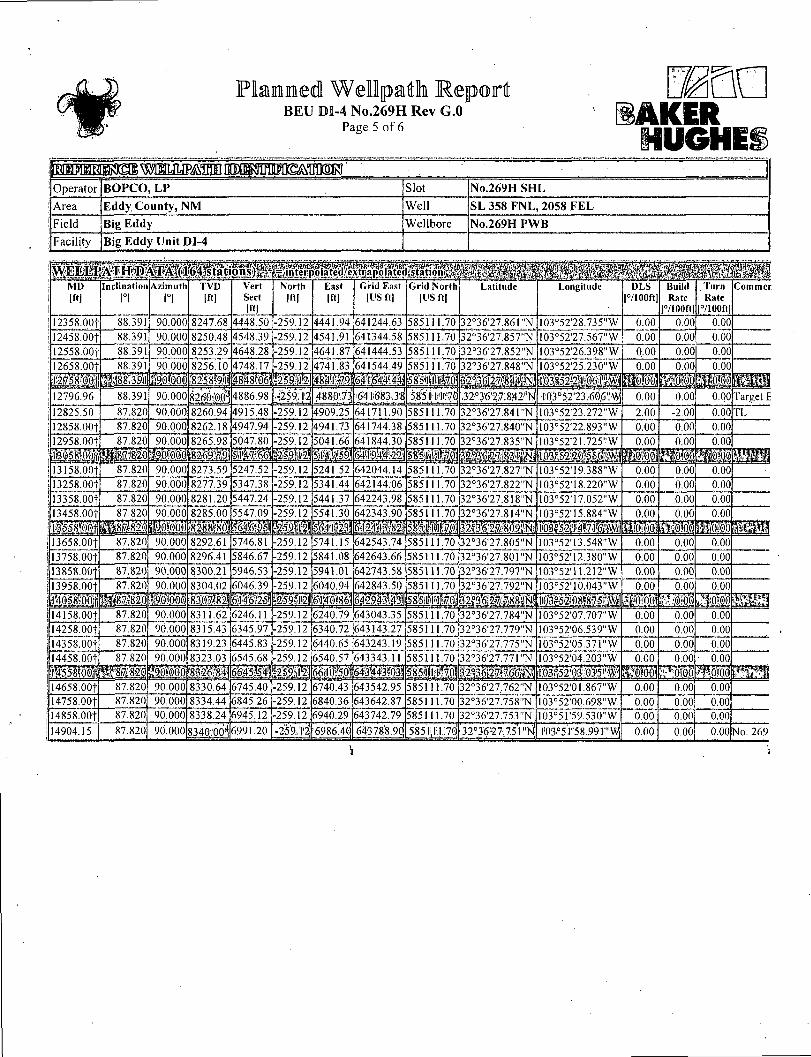
I2358.00f 88.391 90.000 8247.68 4448.50 -259.12 4441.94 641244.63 585111.70 32036,27.861"N I03°5228.735"W 0.00 0.00 0.00
12458.00f 88.391 90.000 8250.48 4548.39 -259.12 4541.91 fefl 344.58 585111.70 32°3627.857"N 103°52'27.567"W '""o.oo 0.00 0.00
I2558.00f 88.391 90.000 8253.29 4648.28 -259.12 4641.87 641444.53 585111.70 32036'27.852"N 103°52'26.398"W 0.00 0.00 0.00 12658.00f 88.391 90.000 8256.10 4748.17 -259.12 4741.83 641544.49 585111.70 32°36'27.848"N 103°5225.230"W 0.00 0.00 0.00
; b,ib1 mm 4848.W saapsi mmM 5"8's!itii!p mm mm i t i s 12796.96 88.391 90.000 8260:()()3! 4886.98 4880:73 641683.38 5.85'i|*l«7,ti 32^3627.842%/ •103o5223.6()6"W| 0.00 0.00 0.00 Target E
12825.50 87.820 90.000 8260.94 4915.48 -259.12 4909.25 641711.90 585111.70 32036'27.841"N 103°5223.272"W 2.00 -2.001 0.00 TL
12858.00t 87.820 90.000 8262.18 4947.94 -259.12 4941.73 641744.38 585111.70 32°36'27.840"N 103°52'22.893,,W 0.00 0.00 0.00
12958.001 87.820 90.000 8265.98 5047.80 -259.12 5041.66 641844.30 585111.70 32°36'27.835"N I03°52'21.725"W 0.00 0.00 0.00
ffe'4:5.8'i0'0>S mmm 'mm I i i i HIP 'mmm wm MM fill 13158.00| 87.820 90.000 8273.59 5247.52 -259.12 5241.52 642044.14 585111.70 32°36'27.827"N 103°52'19.388"W 0.00 0.00 0.00
13258.001 87.820 90.000 8277.39 5347.38 -259.12 5341.44 642144.06 585111.70 32°36'27.822"N 103°52'18.220"W 0.00 0.00 0.00 13358.00f 87.820 90.000 8281.20 5447.24 -259.12 5441.37 642243.98 585111.70 32°36'27.818"N 103°52'17.052"W 0.00 0.00 0.00
13458.00| 87.820 90.000 8285.00 5547.09 -259.12 5541.30 642343.90 585111.70 32°36'27.814"N 103°52'15.884"W o.ob 0.00 0.00
i f f i l i l mml Sfg$ i j l i mm l i l i i i wmmm ! 4 "lA1
mm I3658.00f 87.820 90.000 8292.61 5746.81 -259.12 5741.15 642543.74 585111.70 32°36'27.805"N 103°52'13.548"W 0.00 0.00 0.00 13758.00f 87.820 90.000 8296.41 5846.67 -259.12 5841.08 642643.66 585111.70 32°36'27.801"N 103°52'12.380"W 0.00 0.00 0.00 13858.00f 87.820 90.000 8300.21 5946.53 -259.12 5941.01 642743.58 585111.70 32°36'27.797"'N 103°52'11.212"W 0.00 0.00 0.00
13958.001 87.820 90.000 8304.02 6046.39 -259.12 6040.94 642843.50 585111.70 32°3627.792"N 103°52'10.043"W 0.00 0.001 0.00 1'4058-OOti 'PWbl .83.0.7 821 6;l'f6.2-5; 6'i40l8r?! m?m 58llfj«liZ0l l^bfoli MM 14158.00f 87.820 90.000 311.62 6246.11 -259.12 6240.79 643043.35 585111.70 32°36'27.784"N I03°52'07.707"W 0.00 0.00 0.00 14258.OOf 87.820 90.000 8315.43 6345.97 -259.12 6340.72 643143.27 5851 11.70 32°36'27.779"N !03°52'06.539"W 0.00 0.00 0.00 14358.00f 87.820 90.000 8319.23 6445.83 -259.12 6440.65 643243.19 585111.70 32°3627.775"N 103°52'05.371"W 0.00 0.00 0.00 14458.00f 87.820 90.000 8323.03 6545.68 -259.12 6540.57 643343.11 585111.70 32°3627.771"N 103°52'04.203"W 0.00 0.00 • 0.00
!.!i3.5.ffiCTI ?9>'Mo: «SII 66151 MS) 6#rjfe.bi i03.°"52'03.035!'\y;
Wool £-.:sili,;:II 14658.00f 87.820 90.000 8330.64 6745.40 -259.12 6740.43 643542.95 585111.70 32°36'27..762"N I03°52'01.867"W 0.00 0.00 0.00 14758.00f 87.820 90.000 8334.44 6845.26 -259.12 6840.36 643642.87 585111.70 32°36'27.758"N 103°52'00.698"W. 0.00 0.00 0.00 14858.00f 87.820 90.000 8338.24 6945.12 -259.12 6940.29 643742.79 585111.70 32°36'27.753"N 103°51'59.530"W 0.00 0.00 0.00
14904.15 j 87.820 90.000 83 40;. OOl 6991.20 -259.12 6986.4o| 643788.90| 585 i; rj.;7o' 32°36!27.75l"Ni il03*>5ii58.991i"^ 0.00 0.00 0.00 No. 269

BEU DI-4 No.269H Rev G.O Page 6 of 6
HAKER HUGHES
Operator BOPCO, L P Slot No.269H SHL
Area Eddy County, N M Well SL 358 F N L , 2058 F E L
Field Big Eddy Wellbore N0.269H P W B
Facility Big Eddy Unit DI-4
H U H 981 Name MD
1ft] TVD
Ift] North
[ft] East [ft]
Grid East [US ft]
Grid North [US ft]
Latitude Longitude Shape
1) Tgt-A 11096.84 ; 3]i;80:96! point
1) Tgt-A
2) Tgt-A.l 11957.52 •' Hfmff ldk '3%%$&^m *;* i[03^2j3j ;i:si'wi point
2) Tgt-A.l
3) Tgt-B 12796.96 MZ&>M :;259wll] ;S!880:73| 64.1i683.38; •':.\585illif,|'bl:' M°£6'0M&M " 1i03.IsI:-2'3:?606 point
3) Tgt-B
4) BEU No.269H PBHL Rev-2 14904.15 r255»;i2 6986.40; .•' :l(05°5iii'-5-8.#ir'>V^ point
4) BEU No.269H PBHL Rev-2 -
Start MD [ft]
End MD [ft]
Positional Uncertainty Model Log Name/Comment Wellbore
26.00 658.00 Generic gyro - northseeking (Standard) BEU DI-4 No. 269H AWB
658.00 1.4904.15 NaviTrak (Standard) No.269H PWB
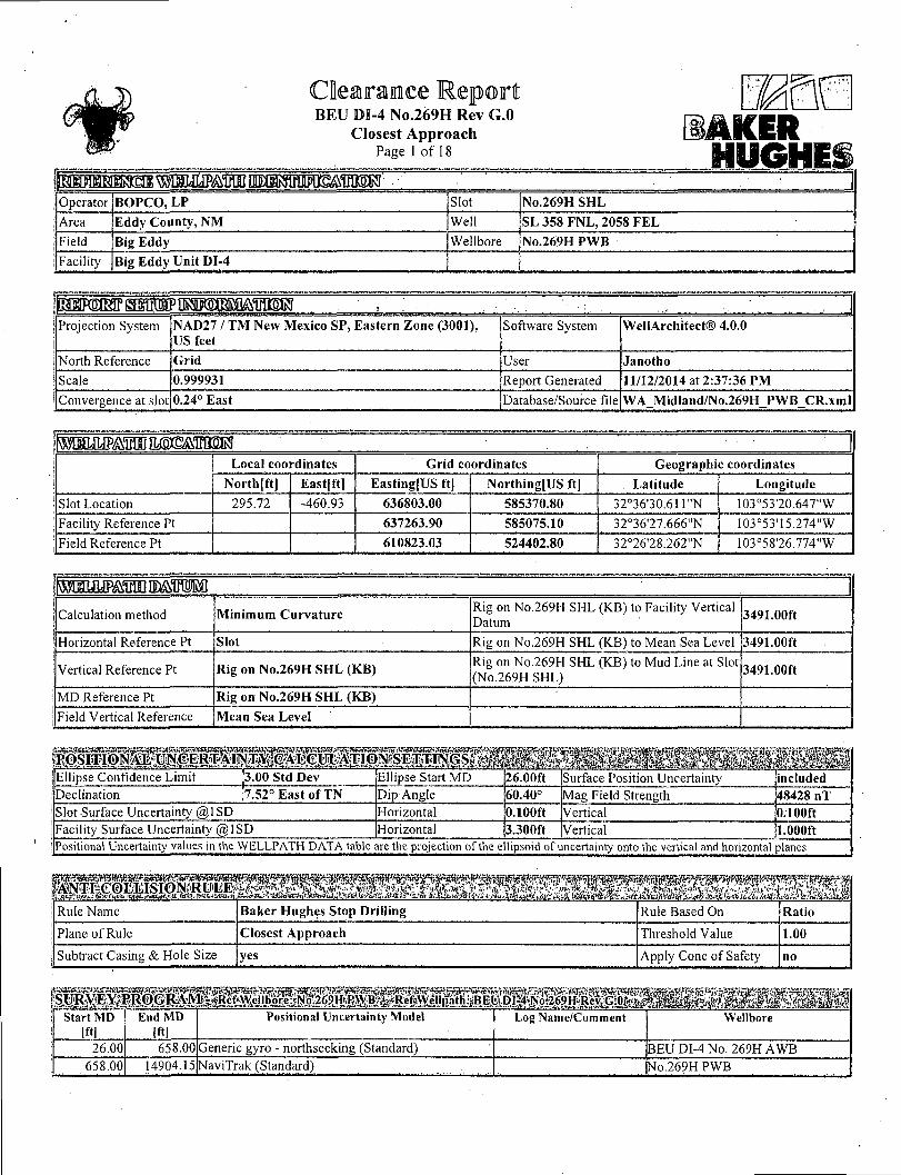
BEU DI-4 No.269H Rev G.O Closest Approach
Page 1 of 18 mm
yucER Operator BOPCO, LP Slot No.269H SHL
Area Eddy County, NM Well SL 358 FNL, 2058 F E L
Field Big Eddy Wellbore No.269H PWB
Facility Big Eddy Unit DI-4
^iNi:(OR\Kv\i . i (b\^HHHHHaBHiHMHHBBi^^^^Hi^i^HWBHi^HHB Projection System NAD27 / TM New Mexico SP, Eastern Zone (3001),
US feet Software System WellArchitect® 4.0.0
North Reference Grid User Janotho
Scale 0.999931 Report Generated 11/12/2014 at 2:37:36 PM
Convergence at slot 0.24° East Database/Source file WA_Midland/No.269H_PWB_CR.xml
Local coordinates Grid coordinates Geographic coordinates
North [ft] Eastfft] Easting[US ft] Northing[US ft] Latitude Longitude
Slot Location 295.72 -460.93 636803.00 585370.80 32°36'30.6H"N 103°53'20.647"W
Facility Reference Pt 637263.90 585075.10 32°36'27.666"N 103°53'15.274"W
Field Reference Pt 610823.03 524402.80 32°26'28.262"N 103°58'26.774"W
Calculation method Minimum Curvature Rig on No.269H SHL (KB) to Facility Vertical Datum 3491.00ft
Horizontal Reference Pt Slot Rig on No.269H SHL (KB) to Mean Sea Level 3491.00ft
Vertical Reference Pt Rig on No.269H SHL (KB) Rig on No.269H SHL (KB) to Mud Line at Slot (No.269H SHL)
3491.00ft
MD Reference Pt Rig on No.269H SHL (KB)
Field Vertical Reference Mean Sea Level
Ellipse Confidence Limit 3.00 Std Dev Ellipse Start MD 26.00ft Surface Position Uncertainty included Declination 7.52° East of TN Dip Angle 60.40° Mag Field Strength 48428 nT Slot Surface Uncertainty @1SD Horizontal 0.100ft Vertical 0.100ft Facility Surface Uncertainty @1SD Horizontal 3.300ft Vertical 1.000ft Positional Uncertainty values in the WELLPATH DATA table are the projection ofthe ellipsoid of uncertainty onto the vertical and horizontal planes
Rule Name Baker Hughes Stop Drilling Rule Based On Ratio
Plane of Rule Closest Approach Threshold Value 1.00
Subtract Casing & Hole Size yes Apply Cone of Safety no
Start MD [ft]
End MD [ft]
Positional Uncertainty Model Log Name/Comment Wellbore
26.00 658.00 Generic gyro - northseeking (Standard) BEU DI-4 No. 269H AWB 658.00 14904.15 NaviTrak (Standard) No.269H PWB

Clearance Report BEU DI-4 No.269H Rev G.O
Closest Approach Page 2 of 18
mn AKER
Operator BOPCO, LP Slot No.269H SHL Area Eddy County, NM Well SL 358 FNL, 2058 FEL Field Big Eddy Wellbore No.269H PWB Facility Big Eddy Unit DI-4
CALCULATION RANGE & CUTOFF * * S ft*"* H 1 From: 26.00ft MD To: 14904.15ft MD C-C Cutoff: (none)
Offset Facility
Offset Slot
i Offset j Offset Offset Well ( Wellbore j Wellpath
C-C Clearance Distance ACR Separation Ratio
Offset Facility
Offset Slot
i Offset j Offset Offset Well ( Wellbore j Wellpath
Ref MD [ft]
Min C-C Clear Dist
[ft]
Diverging from MD
Ift]
RcfMDof Min Ratio
Iftl
Min Ratio
Min Ratio Dvrg from
[ft]
ACR Status
Big Eddy Unit D H
No.27IH SHL
SL 358 FNL, 2078 FEL N0.271HPWB Rev-E.O 658.00 21.59 14904.15 7532.59 14904.15 .'FAIL 1
Big Eddy Unit DI-4
N0.27IH SHL
SL 358 FNL, 2078 FEL
BEU DI-4 No. 27IH AWB
BEU DI-4 No. 271H AWP 1989.33 11.22 1989.33 2026.00 1.07 13926.00 PASS
Big Eddy Unit DI-4
No.264H SHL No.264H No.264H AWP AWP - Final 7536.97 324.15 7536.97 7579.00 7.15 11158.00 PASS
Big Eddy Unit DM
NO.270H SHL NO.270H NO.270H AWP AWP - Final 7458.00 363.48 7458.00: 7726.00 7.97 12826.00 PASS

BEU DI-4 No.269H Rev G.O Closest Approach
Page 3 of 18 (AKER
R » J M < ' \'."
Operator BOPCO, LP Slot No.269H SHL Area Eddy County, NM Well SL 358 FNL, 2058 FEL Field Big Eddy Wellbore No.269H PWB Facility Big Eddy Unit DI-4
1558.00f 1558.00 PASS 1658.00f 1658.00 1.78 1.43 1658.00 1658.00 -0.10 -20.10 265.02 21.62 8.22 2.63 PASS 1758.00f 1758.00 1.78 1.43 1758.00 1758.00 -0.10 -20.10 265.02 21.62 8.87 2.44 PASS 1858.00- 1858.00 1.43 1858.00 1858.00 -0.10 265.02 2.28 PASS
mm 2058.001 2058.00 1.78 .43 2058.00 2058.00 -0.10 -20.10 265.02 21.62 10.86 1.99 PASS 21.58.00f 2158.00 .78 1.43 2158.00 2158.00 -0.10 -20.10 265.02 21.62 11.54 1.87 PASS 2258.00f 2258.00 1.78 1.43 2258.00 2258.00 -0.10 -20.10 265.02 21.62 12.22 .77 PASS 2358 OOf 2358.00 1.78 1.43 2358.00] .2358.00 -o.io 12.90 1.68 PASS
2558. OOf 2558.00 .78 1.43 2558.00! 2558.00 -0.10 -20.10 265.02 21.62 14.28 1.51 PASS 2658.00f 2658.00 1.78 1.43 2658.00 2658.00 -0.10 -20.10 265.02 21.62 14.98 1.44 PASS 2758.00t 2758.00 1.78 2858.00f 2858.00 1.78
messmi
.43 2758.00j 2758.00 -0.10 -20.10 1.43 2858.00 2858.00 -0.10
265.02 265.02
21.62, 15.68 1.38 PASS 21.62 16.37 -20.10 1.32 PASS
m 3058.00f 3058.00 1.78 1.43 3058.00 3058.00 -0.10 -20.10 265.02 21.62 17.78 1.22 PASS 3158.00f 3158.00 1.78 1.43 3158.00 3158.00 -0.10 -20.10 265.02 21.62 18.48 1.17 PASS 3258.00^ 3258.00 1.78 .43 3258.00 3258.00 -0.10 -20.10 265.02 21.62 19.18 .13 PASS 3358.OOf 3358.00 .78 3358.00 3358.00 -0.10 -20.10 265 02 21.62 19.89 1.09 PASS
3558.00f 3558.00 .78 1.43 3558.00 3558.00 -0.10 -20.10 265.02 21.62 21.30 .01 PASS 3658.00f 3658.00 1.78 .43 3658.00 3658.00 -0.10 -20.10 265.02 21.62 22.01 0.98 I-A11:. 3758.00f 3758.00 1.78 1.43 3758.00 3758.00 -0.10 -20.10 265.02 21.62, 22.72 0.95 FAIL. 3858.00f 3858.00 1.78 1.43 3858.00 3858.00 -0.10
958VOO:II,-V; 13958.00 w^rmMM -20.10 265.02 21.62, 23.43 0.92 FAIL
S i l l l •••.265M ••mm* SII •mm 4058.00f 4058.00 1.78 1.43 4058.00 4058.00 -0.10 -20.10 265.02 21.62 24.85 0.87 FAIL 4158.00f 4158.00 .78 1.43 4158.00 4158.00 -0.10 -20.10 265.02 21.62 25.56 0.85 PAIL 4258.00f 4258.00 1.78 1.43 4258.00 4258.00 -0.10 -20.10 265.02 21.62 26.27 0.82 FAIL 4358 OOf 4358.00 1.78 1.43 . 4358.00, -0.10 -20.10 265.02
h"£2jl)0'2l 21.62 26.98 0.80 FAIL
35 mm I FAIL' 4558.00f 4558.00 1.78 1.43 4558.00 4558.00 -0.10 -20.10 265.02 21.62 28.40 0.76 •1-AIL 4658.00f 4658.00 .78 1.43 4658.00 4658.00 -0.10 -20.10 265.02 21.62 29.12 0.74 I-AIL 4758.00f 4758.00 1.78 1.43 4758.00! 4758.00 -0.10 -20.10 265.02 21.62 29.83 0.72 FAIL 4858.00f 4858.00 1.78. 1.43 4858.001 4858.00
mm* -0.10 -20.10 265.02 21.62 30.54 0.71 mm
mm mi "mm •MM

B E U D I - 4 N o . 2 6 9 H R e v G.O
Closes t A p p r o a c h
Page 4 o f 18
Operator BOPCO, LP Slot No.269H SHL Area Eddy County, NM Well SL 358 FNL, 2058 FEL Field Big Eddy Wellbore No.269H PWB Facility Big Eddy Unit DI-4
6158.001 6158.00 1.78 1.43 6158.00 6158.00 -0.10 -20.10 265.02 21.62 39.83 0.54 [ F A I L 6258.00t 6258.00 1.78 1.43 6258.00 6258.00 -0.10 -20.10 265.02 21.62 40.55 0.531 FAIL. 6358.00t 6358.00 1.78 .43 6358.00 6358.001
IBSS^fiol -0.10 -20.10 265.02 21.62 41.26
i ' n o 0.52i FAIL 1
^M58;0.0 FAIL 6558.00f 6558.00 1.78 1.43 6558.00 6558.00 -0.10 -20.10 265.02 21.62 42.69 0.51 FAIL 6658.00f 6658.00 1.78 1.43 6658.00 6658,00 -0.10 -20.10 265.02 21.62 43.41 0.50 FAIL 6758.001 6758.00 .78 1.43 6758.00 6758.00 -0.10 -20.10 265.02 21.62 44.12 0.49 -AIL 6858.00
%Ȥoti 6858.00 1.43
nA»,nWI'/4J.
6858.00,
?y769S8V0d
6858.00
n n i -0.10
MM. -20.10 265.02 21.62 44.84 0.48 FAIL -20: 265:02 S S I FAIL
7058.00f 7058.00 1.78 1.43 7058.00 7058.00 -0.10 -20.10 265.02 21.62 46.27 0.47 FAIL 7158.00f 7158.00 .78 1.43 7158.00 7158.00 -0.10 -20.10 265.02 21.62 46.99 0.46 FAIL 7258.00f 7258.00 1.78 1.43 7258.00 7258.00 -0.10 -20.10 265.02 21.62 47.71 0.45 FAIL 7358.00f 7358.00 7358.00 7358.00 -0.10 -20.10 265.02 21.62 48.42 0.45; FAIL.
S3 e>i.7M8»0 •7458.00 ' -204 •!i265V02 •>2l.:;62.e.:49.14 «g&:m FAIL 7532.59 7532.59 1.78 1.43 7532.59 7532.59 -0.10 -20.10 265.02 21.62 49.67 0.44 FAIL 7558.00t 7557.99 1.59 1.96 .7557.99 7557.99 -0.10 -20.10 265.62 22.13 49.86 0.441 I'AIL I 7658.00f 7657.00 -2.76 14.33 7657.00 7657.00 -0.10 -20.10 274.42 34.53 50.93 0.68 FAIL 7758.00 7752.23 -12.76 42.72 7752.23 ^ 7752.23 -0.10 -20.10 281.40 64.08 52.94 1.21 PASS
X 7840.78 -28.T0 MMM Mm -2011Q •284':7.5 l'l:0.-00 MM ''ASS',1 7958.00f 7919.97 -48.31 143.67 7919.97 7919.97 -0.10. -20.10 286.40 170.72 56.12 3.04 PASS 8058.00f 7987.39 -72.79 213.17 7987.39 7987.39 -0.10 -20.10 287.31 244.34 57.21 4.27 PASS 8158.00f 8041.00 -100.78 292.66 8041.53 8041.53 -0.11 -20.10 287.84 328.56 57.99 5.67 PASS 8232.59 8070.99 -123.45 357.02 8079.84
^•8258:00^ 8079.80 -1.59 -20.10 287.91
287.86!
396.42 58.49 6.78 PASS •Tpgi9J68. 4,li3'il:38 ;3t7,9'3jH :809M9,r • T2'.57I .-20. K'58.'6'.l mm 8358.00f 8113.89 -162.59 468.17 8142.57 8142.00 -9.53, -20.10 287.41 512.48 59.04 8.68 PASS
8432.59 8139.40 -185.87 534.29 8184.56 8182.99 -18.62 -20.10 286.79 580.71 59.41 9.77 PASS 8458.00t 8147.87 -193.60 556.96 8199.28 8197.18 -22.51 -20.10 286.51 603.91 59.54 10.14 PASS 8558 OOf
•i:'8658.0()ti
8176.82 -219.95 648.93 8252.41 8247.48 -39.57 -20.10 285.09, 696.52 59.99 11.61 PASS •8198.55 ^-239.63 .^-20,1 • 283.47 '::-7ffl1b,lM ^6031
8758.00t 8212.83 -252.43 842.58 8323.84 8312.19 -69.70 -20.10 281.96 887.41 60.58 14.65 PASS 8858.00f 8219.51 -258.19 942.15 8337.43, 8324.05 -76.33 -20.10 280.70 984.85 60.67 16.23 PASS 8888.96 8220.01 -258.54 973.11 8338.40 8324.89 -76.81 -20.10 280.37 1015.13 60.67 16.73 PASS
8220.33, -258.56 8958.00 1042.14 8338.84, 8325.28; -77.03 -20.10 279.70: 1082.74 60.65 17.85; PASS :felrlj42:.i;|!4; -20UO, 278.8ri .1.80:97; -'60.62 a9f8:

Clearaimce Report BEU DI-4 No.269H Rev G.O
Closest Approach Page 5 of 18
AKER
Operator BOPCO, L P Slot No.269H SHL
Area Eddy County, N M Well SL 358 F N L , 2058 F E L
Field Big Eddy Wellbore No.269H PWB
Facility Big Eddy Unit DI-4
Ref MD [ft]
Ref TVD [ft]
" Ref North [ft]
Ref East |ft]
Offset MD [ft)
Offset TVD [ftl
Offset North [ft]
Offset East. 1 Horiz [ft] | Bearing
l°l
C-C Clear Dist
[ftl
ACR MASD
[ft]
Sep Ratio
ACR Status
9158.00f 8221.23 -258.61 1242.14 8340.12 8326.38 -77.67 -20.10 278.16 1279.47 60.61 21.11 PASS .
9258.001 8221.68 -258.64 1342.14 8340.75 8326.93 -77.99 -20.10 277.55 1378.19 60.60 22.74 PASS
9358.001 8222.14 -258.67 1442.14 8341.39 8327.48 -78.31 -20.10 277.03 1477.08 60.60 24.38 PASS
9458.00t 8222.59 -258.69 1542.14 11117.87 9047.63 -1598.17 1527.89) 180.61 1573.24 112.80 13.95 PASS
I S I S ' B H i i | S | g | 8 j | 2 mmm. l i i i l l i mmm i l i i i i i l 9658.00t 8223.49 -258.74 1742.13 • 11317.86 9051.03 -1598.20 1727.851 180.61 1574.54 123.55 12.74 PASS
9758.00t 8223.94 -258.77 1842.13 11417.85 9052.74 -1598.21 1827.83 180.61 1575.18 129.04 12.21 PASS
9858.00t 8224.40 -258.80 1942.13 11517.84 9054.44 -1598.23 1927.80 180.61 1575.83 134.60 11.71 PASS
9958.00f 8224.85 -258.82 2042.13 11617.83 9056.14 -1598.24 2027.78 180.61 1576.48 140.22 11.24 PASS
mmm mmm mmmm i l i j p ( i i ^ » | ^ i i 8 : o ) g 2 ffiP<l MM 10158.001 8225.75 -258.87 2242.13 11817.82 9059.54 -1598.27 2227.74! 180.62 1577.78 151.59 10.41 PASS 10258.00f 8226.21 -258.90 2342.13 11917.81 • 9061.24, -1598.29 2327.72 180.62 1578.43 157.34 10.03 PASS 10358.00t 8226.66 -258.93 2442.13 12017.80 9062.94 -1598.31 2427.69 180.62 1579.09 163.12 9.68 PASS 10458.00f 8227.11 -258.95 2542.13 12117.79 9064.64 -1598.32 2527.67] 180.62 1579.74 168.93 9.35 PASS
mmm l lf8lp|5:6; fc^g'8l§8 mmmm I0658.00f 8228.02 -259.01 2742.12 12317.78 9068.04 -1598.35 2727.63] 180.62 1581.05 '180.63 8.75 PASS 10758.00f 8228.47 -259.03 2842.12 12417.77 9069.74 -1598.37 2827.60 180.62 1581.70 186.51 8.48 PASS 10858.00| 8228.92 -259.06 2942.12 12517.76 9071.44 -1598.38 2927.58 180.62 1582.36 192.41 8.22 PASS
10958.00| 8229.37 -259.08 3042.12 12617.75 9073.14 -1598.40 3027.56] 180.62 ' 1583.01 198.32 7.98 PASS
sf%259:fci! mmm i mmmm wmmm Mmmmmm ' !204'.25 wmm 11096.84 8230.00 -259.12 3180.96 12756.58 9075.50 -1598.42 3166.37| 180.62 1583.92 206.56 7.67 PASS 11107.27 8230.07 -259.12 3191.39 12767.02 9075.68 -1598.42 3176.80j 180.62 1583.98 207.18 7.65 PASS 11158.00f 8230.48 -259.12 3242.12 12817,74 9076.54 -1598.43 3227.52 180.63 1584.23 210.21 7.54 PASS
•' 11258.00f 8231.30 -259.12 3342.11 12917.74 9078.24 -1598.45 3327.50 180.63 1584.72 216.18 7.33 PASS ,
mmmm i e s « 2 § 9 i ^ mm mmmm ?§Pif5,8l5SO" 11458.001 8232.93 -259.12 3542.11 13117.73 9081.65 -1598.48 3527.46 180.63 1585.69 228.17 6.95 PASS 11558.00j 8233.74 -259.12 3642.10 13217.72 9083.35 -1598.49 3627.44 .180.63 . 1586.18 234.18 6.77 PASS 11658.00| 8234.56 -259.12 3742.10 13317.72 9085.05 -1598.51 3727.43 180.63 1586.67 240.20 6.61 PASS 11758.00f 8235.37 -259.12 3842.10 13417.72 9086.75 -1598.52 3827.4l| 180.63 1587.15 246.22 6.45 PASS
1^8-58^01 •"'.'•8236; 1,9 ^ i i f s i i ^ i l '. '.:.:. ' ";90'88:45 E^;21C-J598:53 -;s; ;;M2^3:9;pii8o^3: mmm :;352!25; •:>6.29 •P>\SS4
11957.52 8237.00 -259.12 4041.61 13617.23 9090.14 -1598.55 4026.89 180.63 1588.13 258.26 6.15 PASS 11958.001 8237.00 -259.12 4042.09 13617.71 9090.15 -1598.55 4027.37 180.63 1588.13 258.29 6.15 PASS : 12014.60 8238.03 -259.12 4098.68 13674.31 9091.11 -1598.56 4083.96 180.63 1588.10 261.75 6.07 PASS 12058.00f 8239,25 . -259.12 4142.0.6 13717.71 9091.85 -1598.57 4127.35] 180.63 1587.85 264.43 6.00 PASS
Ife'3l-!ii598>59; iPASSrl 12258.00f 8244.87 -259.12 4341.98 13917.69 9095.25 -1598.60 4327.31 180.63 1586.69 276.84 5.73 PASS 12358.00f 8247.68 -259.12 4441.94 14017.69 9096.95 -1598.62 4427.29 180.63 1586.11 283.06 5.60 PASS 12458.00| 8250.48 -259.12 4541.91 14117.68 9098.65 -1598.63 • 4527.27 180.63 1585.53 289.30 5.48 PASS 12558.001 8253.29 -259.12 4641.87 14217.67 9100.35 -1598.65 4627.25 180.63 1584.95 295.54 5.36 PASS
.V-'8256i'f6 I^«^l te98v66 ! i ^ > 4 » 2 l 3 : p i : l ! 8 0 ^ ,;'30F:7.9; PASS;! 12758.00t 8258.91 -259.12 4841.79 14417.66 9103.75 -1598.68 4827.2l| 180.62 1583.79 308.05 5.14 PASS 12796.96 8260.00 -259.12 4880.73 14456.62 9104.42 -1598.69 4866.161 180.62 1583.57 310.49 5.10 PASS 12825.50 8260.94 -259.12 4909.25 14485.15 9104.90 -1598.69 4894.69 180.62 1583.33 312.30 5.07 PASS 12858.00| . 8262.18 . -259.12 4941.73 14517.65 9105.45 -1598.69 4927.18 180.62 1582.97 314.36 5.04 PASS
^••,826§v98 y^f»iqi598v^il ;4f;.*502^li|g.a8fii62 ^320ffl3' 'PjA'SS.)

BEU DI-4 No.269H Rev G.O Closest Approach
Page 6 of 18 HUGHES ;/ ^ .'• ^y:..' • : j
Operator BOPCO, LP Slot No.269HSHL
Area Eddy County, NM Well SL 358 FNL, 2058 FEL
Field Big Eddy Wellbore No.269H PWB
Facility Big Eddy Unit DI-4
j Slot Surface Uncertainty @ 1 SD Horizontal jO.lOOft Vertical jo. 100ft
[Facility Surface Uncertainty @1SD Horizontal |3.300ft Vertical Jl.OOOft
timm mmmmmm wmsffl Start MD \ [ftl
End MD [ft]
Positional Uncertainty Model Log Name/Comment Wellbore
26.00 • 600.00 Generic gyro - northseeking (Standard) No.271HPWB 600.00 16548.87 NaviTrak (Standard) iNo.271HPWB .
MD Reference: Rig on No.271H SHL (KB) \Offset TVD & local coordinates use Reference Wellpath settings \(See WELLPATH DATUM on page 1 of this report)
Ellipse Start MD j26.00ft
Clearance Report BEU DI-4 No.269H Rev G.O
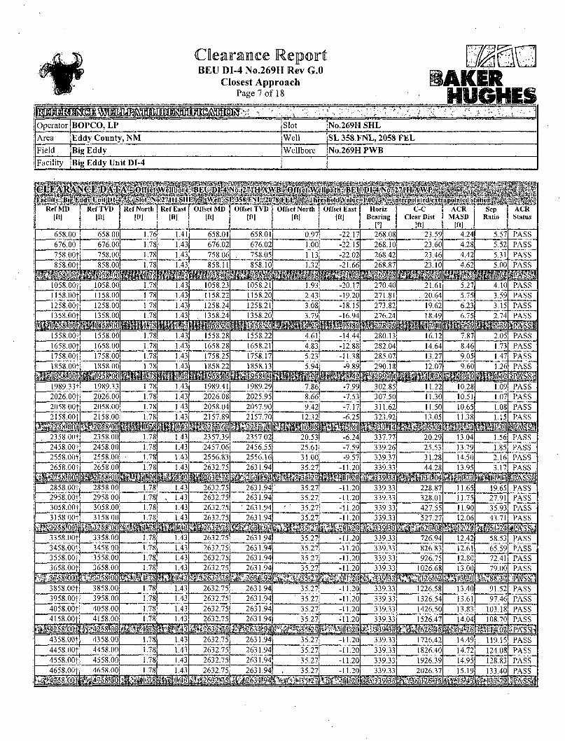
Closest Approach Page 7 of 18 HUGHES
Operator]BOPCO, LP Slot No.269H SHL
Area Eddy County, N M Well SL 358 F N L , 2058 F E L
Field Big Eddy Wellbore No.269H PWB
Facility Big Eddy Uni t DI-4
Ref MD j Ref TVD [ft] j [ftl
mm Ref North
[ft] Ref EasT
[ft]
mmmmm SBEUjDlpJ
Offset MD [ftl
'358lFNlSaO M tKiHi UHAOU y&KH U»#Gl
Offset TVD [ft]
•/'BijOffsctiW
Offset North [ft]
W W ;llpath:;BEl csholulValue Offset East
[ft]
mmtm: P'.OOjgM
Horiz Bearing
[°l
itenpolated/cxtr C-C
Clear Dist Iftl
apolated s ACR
MASD [ftl
mM 1*1-"'
Sep Ratio
•r-..-. .:.v.. ACR Status
658.00 658.00 1.76 1.41 658.01 658.01 0.97 -22.17 268.08 23.59 4.24 5.57 PASS 676.00 676.00, 1.78 1.43 676.02 676.02 1.00 -22.15 268.10 23.60 4.28 5.52 PASS 758.00f 758.00 1.78 1.43 758.06 758.05 1.13 -22.02 268.42 23.46 4.42 5.31 PASS 858.00f 858.00 1.78 1.43 858.11 858.10 1.32 -21.66 268.87 23.10 4.62 5.00 PASS
mmm m i l l *> mm 1058.00f 1058.00 1.78 1.43 1058.23 1058.21 1.93 -20.17 270.40 21.61 5.27 4.10 PASS 1158.00f 1158.00 1.78 1.43 1158.22 1158.20 2.43 -19.20 271.81 .. 20.64 5.75 3.59 PASS 1258.00f 1258.00 .1.78 1.43 1258.24 1258.21 3.08 -18.15 273.82 19.62 6.23 3.15 PASS 1 58 OOf 1358 00 1.7"
itfJ/J:'. 1.43 . 1358.24 1358.20 3.79 -16.94 276.24 18.49 6.75 2.74 PASS 1 58 OOf 1358 00 1.7"
itfJ/J:'. : rig •^-•L-15,8^4
. . • -"•/•-.-JOij!
1558.00| 1558.00 1.78 1.43 1558.28 1558.22 4.61 -14.44 280.13 16.12 7.87 2.05 PASS 1658.00j 1658.00 1.78 1.43 1658.28 1658.21 4.83 -12.88 282.04 14.64 8.46 1.73 PASS 1758,00} 1758.00 1.78 1.43 1758.25 1758.17 5.23 -11.38 285.07 13.27 9.05 1.47 PASS 1858.00f
;il|'gip.l8?6;6'it 1858.00 1.78 1.43 1858.22 1858.13 5.94 -9.89 290.18 12.07 9.60 1.26 PASS 1858.00f
;il|'gip.l8?6;6'it 1858.00
1 si "8
mm raagg &y|a5:8j.('4 :•:•/:sM2 ms ;^ . .^ : i : , - :28- ^is'sl
1989.33f 1989.33 1.78 1.43 1989.41 1989.29 7.86 -7.99 302.85 11.22 10.28 1.09 PASS 2026.00j 2026.00 1.78 1.43 2026.08 2025.95 8.66 -7.53 307.50 11.30 10.51 1.07 PASS ;
2058.001 2058.00 1.78 1.43 2058.04 2057.90 9.42 -7.17 311.62 11.50 10.65 1.08 PASS 2158.00j 2158.00 1.78 1.43 2157.89 2157.70 12.32 -6.25 323.92 13,05 11.38 1.15 PASS
. : : . . . ; 25£ j j : sami ^'liifel&i^ofl SKiOl . 2358.00f 2358.00 1.78 2357.39 2357.02 20.53 -6.24 337.77 20.29 13.04 1.56 PASS
2458.00} 2458.00 1.78 1.43 2457.06 2456.55 25.61 -7.59 339.26 25.53 13.79 1.85 PASS 2558.001 2558.00 1.78 1.43 2556.83 2556.16 31.00 -9.57 339.37 31.28 14.50 2.16 PASS 2658.00f 2658.00 1.78 1.43 2632.75 2631.94 35.27 -11.20 339.33 44.28 13.95 3.17 PASS
--I' il . -1*10 mm mmmm :- •>:1-T3 P I
2858.00f 2858.00 1.78 1.43 2632.75 2631.94 35.27 -11.20 339.33 228.87 11.65 19.65 PASS 2958.001 2958.00 1.78 , 1.43 2632.75 2631.94 35.27 -11.20 339.33 328.01 11.75 27.91 PASS 3058.00f 3058.00 1.78 1.43 2632.75 ' 2631.94 ' ' 35.27 -11.20 339.33 427.55 11.90 35.93 PASS 3158.00| 3158.00 1.78 1.43 2632.75 2631.94 35.27 -11.20 339.33 '527.27 12.06 43.71 PASS
r ,-| ifel ^^gitiiib; mmm. gjg?iri62|l68 !tiiiii m&4 3358.00f . 3358.00 1.78 1.43 2632.75 ' 2631.94 35.27 -11.20 339.33 726.94 12.42 58.53 PASS 3458.00} 3458.00 1.78 1.43 2632.75 2631.94 35.27 -11.20 339.33 826.83 12.61 65.59 PASS ;
3558.00j •3558.00 1.78 1.43 2632.75 2631.94 35.27 -11.20 339.33 926.75 12.80 72.41 PASS 3658.00* 3658.00 1.78 1.43 2632.75 2631.94 35.27 -11.20 339.33 1026.68 13.00 79.00 PASS
?1^5l58f0O: mmm i?Mvr*..'fe»'3>5.t-2J &S9I3 1
mm. 3858.001 3858.00 1.78 1.43 2632.75 2631.94 35.27 -11.20 339.33 1226.58 13.40 91.52 PASS 3958.001 3958.00 1.78 1.43 2632.75 2631.94 ' 35.27 -11.20 " 339.33 1326.54 13.61 97.46 PASS 4058.001 4058.00 1.78 1.43 2632.75 2631.94 35.27 -11.20 339.3.3 1426.50 13.83 103.18 PASS 4158.00* 4158.00 1.78 1.43 2632.75 2631.94 - 35.27 -11.20 339.33 1526.47 14.04 108.70 PASS
mmm mwmm SSiiMO^ apA'ssH 4358.001 4358.00 1.78 1.43 2632.75 2631.94 35.27 -11.20 339.33 1726.42 14.49 119.15 PASS 4458.OOf 4458.00 1.78 1.43 2632.75 2631.94 35.27 -11.20 339.33 1826.40 14.72 124.08 PASS 4558.001 4558.00 1.78 1.43 2632.75 2631.94 35.27 -11.20 339.33 1926.39 14.95 128.83 PASS 4658.00f 4658.00 1.78 1.43 2632.75 2631.94 35.27 -11.20 339.33 2026.37 15.19 133.40 PASS
• pM8?rMH i|lfMt5'3tif9^ pg339.l3| mmm@k mmm »s~sa
Clearance Report BEU DI-4 No.269H Rev G.O
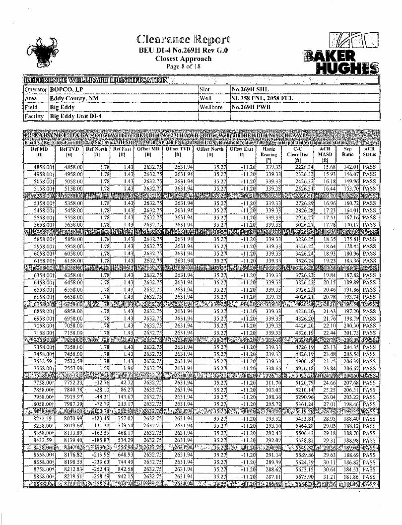
Closest Approach Page 8 of 18
tAKER mmm r - - i • - . - * • -? • ..
Operator BOPCO, LP Slot No.269H SHL Area Eddy County, NM Well SL 358 FNL, 2058 FEL Field Big Eddy Wellbore No.269H PWB Facility Big Eddy Unit DI-4
Ref MD [ft]
Ref TVD ACR Status
• 4858.001 4858.00 1.78 1.43 2632.75 2631.94 35.27 -11.20 339.33 2226.34 15.68 142.01 PASS 4958.001 4958.00 .78 1.43 2632.75 2631.94 35.27 11.20 339.33 2326.33 15.93 146.07 PASS
5058.00 5058.00 .78 1.43 2632.75 2631.94 35.27 -11.20 339.33 2426.32 16.18 149.96 PASS
5158.00f 5158.0(1 1.78 1.43; 2632.75 2631.94| 35.27 11.20 339.33 2526.31
mmm. 1644
Mm 153.70 PASS
5358.00f 5358.00 1.78 .43 2632.75 2631.94 35.27 -11.20 339.33 2726.29 16.96 160.72 PASS
5458.00f 5458.00 .78 1.43 2632.75 2631.94 35.27 11.20 339.33 2826.28 17.23 164.01 PASS 5558.00f 5558.00 1.78 1.43 2632.75 2631.94 35.27 -11.20 339.33 2926.27 17.51 167.16 PASS
1.78 1.43 -11.20 17.78 170.17
iVfatoMp l PASS
5858.00 5858.00 1.78 1.43 2632.75 2631.94 35.27 .20 339.33 3226.25 18.35 175.81 PASS 5958.00} 5958.00 1.78 1.43! 2632.75 2631.94 35.27 -11.20 339.33 3326.25 18.64 178.45 PASS 6058.00} 6058.00 1.78 1.43 2632.75 2631.94 35.27 -11.20 339.33 3426.24 18.93 180.96 PASS
6158.00 .78 2632.75 2631.94 35.27 11.20 339.33 19.23 183.36 PASS IPJSSI fe25;8M0 mm 6358.00- 6358.00 .78 1.43: 2632.75 2631.94 35.27 -11.20 339.33 3726.23 19.84 187.82 PASS
6458.00} 6458.00 1.78 1.43! 2632.75 2631.94 35.27 -11.20 339.33 3826.22 20.15 .189.89 PASS
6558.001 6558.00 1.78 1.43 2632.75 2631.94 35.27 -11.20 339.33 3926.22 20.46 191.86 PASS 6658.00^ 6658.00 1.78 1.43 2632.75 2631.94
#^1M:9I 35.27 -11.20 339.33
ft"»,;'A 4026.21 20.78 193.74
team PASS
mm .6758,00 WW, 6858.00} 6858.00 1.78 1.43 2632.75 2631.94 35.27 -11.20 339.33 4226.20 21.43 197.20 PASS 6958.001 6958.00 .78 .43 2632.75, 2631.94 35.27 -11.20 339.33 4326.20 21.76 198.79 PASS 7058.00+ 7058.00 1.78 1.43 2632.75, 2631.94 35.27 -11,20 339.33 4426.20 22.10 200.30 PASS 7158.00J 7158.00
fiscal . 1.78 1.43 2632.75 2631.94
mm 35.27 11.20 339 33 4526.19
mmm 22.44
mm 201.73
y203 :0 j PASS
il 7358.00t 7358.00 1.78 1.43 2632.75 2631.94 35.27 11.20 339.33 4726.19 23.13 204.35 PASS 7458.00-f 7458.00 1.78 1.43 2632.75 2631.94 35.27 .20 339.33 4826.19 23.48 205.54 PASS 7532.59 7532.59 1.78 1.43 2632.75 2631.94 35.27 .20 339.33 4900.78 23.75 206.39 PASS
7557.99 2631.94 35.27 -11.20 338.65 4926.18 C'502-5.
23.84 206.67 PASS
111111 7758.OOf 7752.23, 12.76 42.72 2632.75 2631.94 35.27, -11.20 311.70 5120.79 24.66 207.68 PASS 7858.00} 7840.78 -28.10 86.27 2632.75 2631.94 35.27 11.20 303.03 5210.14 25.25 206.31 PASS 7958.00} 7919.97 -48.3! 143.67 2632.75 2631.94 35.27 -11.20 298.36 5290.96 26.04 203.22 PASS 8058.00}
JijglO'ofli 7987.39 -72.79
S i l l 213.17 2632.75 2631.94 35 27 •11.20 295.72 5361.24 27.01 198.46 PASS
IBMSSI '49MM 8232.59 8070.99 -123.45 357.02 2632.75 2631.94 35.27 -11.20 293.32 5453.81 28.95 188.40 PASS 8258.OOt 8079.68 -131.38 379.54 2632.75 2631.94 35.27 -11.20 293.10 5464.28 29.05 188.12 PASS 8358.00} 8113.89 162.59 468.17 2632.75 2631.94 35.27 -11.20 292.43 5506.42 29.18 188.70 PASS 8432.59 8139.40, -185.87 534.29
556.96! 2632.75 2631.94
"'!i263"r:9)t 35.27 -11.20 292.07 5538.82 29.31
WEE 188.98 PASS
8458!0(),ti fer„ -8I:47;87, r3x27. ffjl j;20 •••5549:83. -'•i89:-os; •PASSH 8558.00} 8176.82 -219.95 648.93 2632.75 2631.94 35.27 -11.20 291.14 5589.86 29.63 188.69 PASS 8658.00} 8198.55 -239.63 744.49 2632.75 2631.94 35.27 -11.20 289.99 5624.39 30.11 186.82 PASS 8758.00} 8212.83 -252.43 842.58 2632.75 2631.94 35.27 -11.20 288.62 5653.15 30.64 184.53 PASS 8858.00} 8219.51 -258.19 942.15 2632.75 2631.94 35.27 -11.20 287.11 5675.90 31.21 181.86 PASS
-!tf'>8888l9.6j»J ' S22();0,l faag258?54^v';9i73^1»! ^263.1.94 286:62 BASS
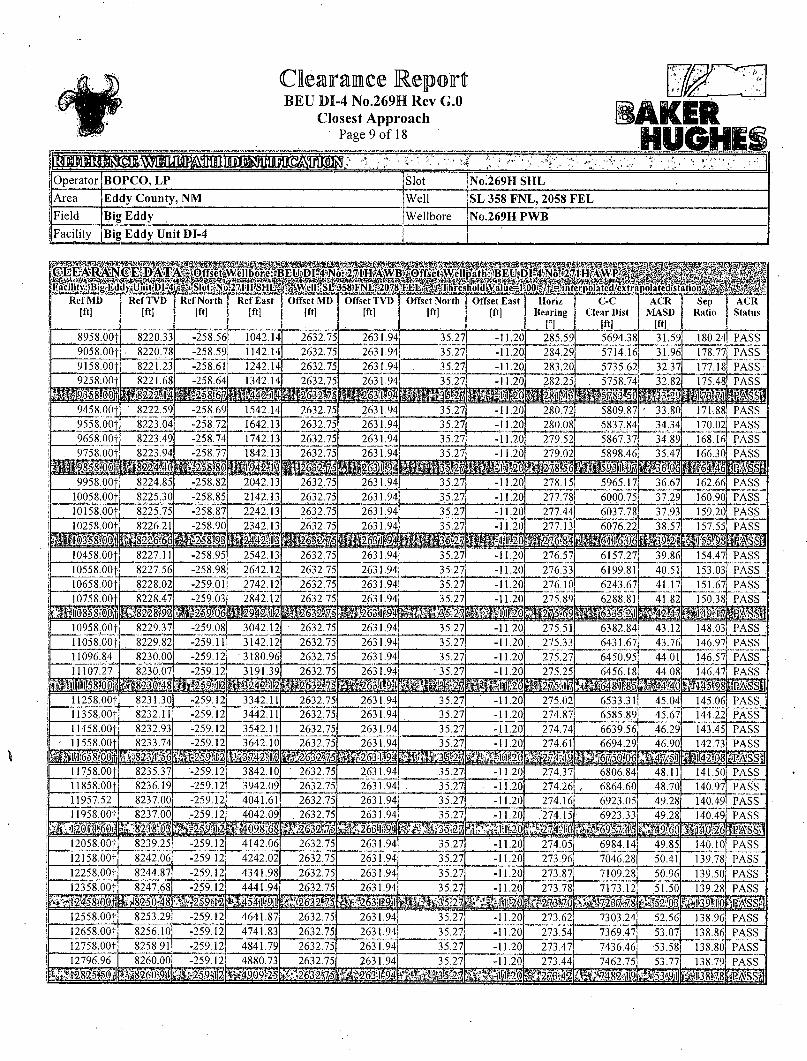
BEU DI-4 No.269H Rev G.O Closest Approach
Page 9 of 18 iAKBR
i - ' : ' \ V" i.
Operator BOPCO, LP Slot No:269H SHL Area Eddy County, NM Well SL 358 FNL, 2058 FEL Field Big Eddy Wellbore No.269H PWB Facility Big Eddy Unit DI-4

BEU DI-4 No.269H Rev G.O Closest Approach
Page 10 of 18
Operator BOPCO, LP Slot No.269H SHL
Area Eddy County, NM Well SL 358 FNL, 2058 FEL
Field Big Eddy Wellbore No.269H PWB
Facility Big Eddy Unit DI-4 j
I5WS8'
Ref MD Iftl
*^ Ref TVD [ft]
12858.00f 8262.18
Ref North Ref East [ft] | [ft]
-259.12 4941.73
Offset MD Iftl
Offset TVD [ftl
2632.75 2631.94 35.27 -11.20 273.40 7504.52 54.07 138.79 PASS.
12958.00+ 8265.98 -259.12 5041.66 2632.75 2631.94 35.27 -11.20 273.33 7573.67 54.56 138.82 PASS 13058.OOf 8269.79 -259.12 5141.59 2632.75 2631.94 35.27 -11.20 273.27 7643.51 55.03 138.89 PASS
13158.00| 8273.59 259.12
i m 2632.75 2631.94
B B 35.27 -11.2(1.
TTiT27i 273 21
HH 7714.01 138 99 PASS
2-58 mm mm 13358.00f 8281.20 -259.12 5441.37
13458:00f 8285.00 -259.12 5541.30 _2632.75 2632.75
2631.94 35.27 -11.20 273.09 7856.93 56.41 139.281 2631.94 35.27 -11.20 273.04 7929.31 56.86 139.46
13558.00- 8288.80 -259.12 5641.23 2632.75 2631.94 35.27 -11.20 272.98 8002.29 57.29 139.68
13858.00 8300.21 -259.12 5941.01 2632.75 2631.94 35.27 -11.20 272.83 8224.64 58.55 .140.47!
13.958.00f 8304.02 -259.12 6040.94 2632.75 •2631.94 35.27 -11.20 272.79 8299.85, 58.96 140.77 PASS 14058.00i 8307.82 -259.12 6140.86 2632.75 2631.94 35.27 -11.20 272.74 •8375.57 59.36 141.10 PASS
8311.62
mm -259.12
mm 6240.79 2632.75 35.27 272.70 8451.80 59 75
HI 14358.00^ 8319.23 -259.12 6440.65 2632.75 2631.94 35.27 -11.20 272.61 8605.71 60.51 142.21
14458.00f 8323.03 -259.12 6540.57 2632.75 2631.94 35.27 -11.20 272.57 8683.37 60.89 142.61 PASS
14558.001 8326.84 -259.12 6640.50 2632.75 2631.94 35.27 -11.20 272.53 8761.49 61.25 143.03 PASS 14658.00f 8330.64
mm* 6740.43 2632.75 2631.94 -11.20 272.50 .8840.04 61.62 143.47 PASS
msmmm ••mmm 14858.00f 8338.24 -259.12 6940.29 2632.75 2631.94 35.27 -11.20 272.43 8998.43 62.32 144.39 PASS 14904.15 8340.00 -259.12 6986.40 2632.75 2631.94 35.27 -11.20 272.41 9035.21 62.48 144 PASS
'Mmmmmm | e t ^ | 0 | % ^ B E fAjJf M H i Slot Surface Uncertainty @ 1 SD Horizontal jO.lOOft jVertical 0.100ft
Facility Surface Uncertainty @1SD Horizontal |3.300ft • jVertical 1.000ft
Start MD [ft]
End MD [ft]
Positional Uncertainty Model Log Name/Comment Wellbore
26.00 2632.75 Generic gyro - northseeking (Standard) Gyro Data <73.95-2632.75> BEU DI-4 No. 271H AWB
MD Reference: Rig on No.271H SHL (KB) \Offset TVD & local coordinates use.Reference Wellpath settings \(See WELLPATH DATUM on page 1 of this report)
Ellipse Start MD |26.00ft

BEU DI-4 No.269H Rev G.O Closest Approach
Page 11 of 18 AKER
1 BR^ni FWAflil dm Operator BOPCO, LP Slot No.269H S H L
Area Eddy County, N M Well SL 358 F N L , 2058 F E L
Field Big Eddy Wellbore No.269H PWB
Facility Big Eddy Uni t DI-4
•~* "'-''"athsAWP^Emal n l f l " \ / n l » J » — 4 - ; —
Ref MD [ft]
Ref TVD [ft]
Ref North [ftl
Ref East [ft]
Offset MD [ft]
Offset TVD [ftl
Offset North [ft]
Offset East [ft]
Horiz \ C-C Bearing \ Clear Dist
1°1 , i Iftl
ACR MASD
Wl
Sep Ratio
ACR Status
658.00 658.00 1.76 1.41 661.71 658.70 -302.21 -154.49 207.15 341.62 4.82 70.82 PASS , 676.00 676.00 1.78 1.43 679.72 676.71 -302.18 -154.46 207.15 341.61 4.92 69.41 PASS ,
758.001 758.00 1.78 1.43 761.82 . 758.81 -302.06 -154.31 207.14 341.43 5.18 65.94 PASS 858.00f 858.00 1.78 ' 1.43 862.17 859.16 -301.96 -153.89 207.08 341 15 '5.58 61.13
9 H PASS ;
ass S E I I I mm ms •< \ : a'?31 '5.58 61.13
9 H PASS ;
1058.00+ 1058.00 1.78 1.43 1063.21 1060.19 -301.66 -152.29 206.87 340.16 6.48 52.49 PASS 1158.00} 1158.00 1.78 1.43 1163.42 1160.39 -301.47 -151.12 206.71 339.47 6.98 PASS 1258.00f 1258.00 1.78 1.43 1262.84 1259.81 -301.26 -150.10 206.57 338.82 7.52 45.03 PASS 1358.00f
mmm 1358.0C 1.78 1.43 1362.93 1359.90 -300.98 -149.53 206.50 338.31 8.12 41.66 PASS 1358.00f
mmm 1358.0C
•¥ : ;g i i59)89 -300.48
^•+. :L!8_8l -148.03
.-::;,':':iS" ~$ Rs'-sl 1558.00f 1558.00 1.78 1.43 1562.73 1559.69 -300.48
^•+. :L!8_8l -148.03 206.31 337.20 9.32 36.16 PASS ;
1658.00| 1658.00 1.78 1.43 1661.87 1658.82 ' -300.50 -147.14 206.17 336.82 9.89 34.061 PASS 1758.00} 1758.00 1.78 • 1.43 1761.52 1758.48 -300.74 -146.24 206.02 336.64 10.43 32.29 PASS 1858.00} 1858.00 1.78 1.43 1862.47 1859.41 -300.95 -145.18 205.84 336.36 10.99 30.61 PASS ;
mmm _- >L1'dLI>j U n i i mmm •>:-l-l'.'-t mm 2058.00f 2058.00 1.78 1.43 2064.19 2061.12 -299.86 -143.96 205.74 334.87 12.35 27.12 PASS : 2158.00+ 2158.00 1.78 1.43 2164.21 2161.14 -299.00 -143.57 205.74 333.92 13.06 25.56 PASS 2258.00} 2258,00 1.78 1.43 2264.32 . 2261.24 -298.17 -143.15 205.74 332.99 13.79 24.16 PASS
2358 00t 235S00 1.78 1.43 2364.76 2361.69 -297.31 -142.47 205.69 331.93 14 5Q 22.88 PASS ;
IKss'l 2358 00t 235S00
m 24111! : I 6 J ! ^ mm: ' I - ' T33 ' i8l 14 5Q 22.88 PASS ;
IKss'l 2558.00+ 2558.00 1.78 1.43 2562.35 2559.27 -296.46 -140.64 205.47 330.35 15.83 20.87 PASS
2658.001 2658.00 1.78 1.43 2661.46 2658.37 -296.59 -139.72 205.32 330.07 16.42 20.10 PASS
2758.00j 2758.00 1.78 1.43 2760.86 2757.76 -297.05 -138.80 205.14 330,09 16.96 19.46 PASS 2858.00" 2858.00 1.78 1.43 2860.53 2857.42 -297.63 -137.80 204.94 330.20 17.48 H8.89 PASS ;
<tmmm mmm, i i i i " ri^mi mm S i t 3058.00f 3058.00 1.78 1.43 3061.16 • 3058.05 -298.41 -136.59 .204.69 330.40 18.55 17.81 PASS . 3158.00f 3158.00 1.78 1.43 3156.73 3153.61 • -299.10 -136.29 204.60 . 330.93 19.05 17.37 rpAss 3258.00+ 3258.00 ' 1.78 1.43 3253.36 3250.23 -300.94 -136.64 204.52 • ' 332.81 19.51 HI7.06 PASS 3358.00f 3358.00 1.78 1.43 3351.74 3348.57 -303.09 -138.10 204.59 335.41 19.95 16.81 PASS ;
fci3ff5;8jo:p' safes g i i S jlb'gg mm p%ss| 3558.00f 3558.00 1 1.78 1.43 3555.78 1 3552.56 -305,99 -142.00 204.99 339.59 20.92 16.24 PASS ;
3658.001 3658.00 1.78 1.43 3656.31 3653.07 -306.95 -143.53 205.15 341.10 21.41 15.93 PASS ! 3758.00} 3758.00 1.78 1.43 3756.41 3753.16 -308.04 -144.68 205.25 342.58 21.90 15.64 PASS 3858.00}. ' 3858.00 1.78 1.43 3857.50 3854.24 -309.06 -145.30 205.27 343.75 i 22.40 15.34 PASS .
if^M9lS#! mimm® mmm mm $$$$ 4058.00} 4058.00 1.78 1.43 4058.09 4054.81 -310.79 -146.96 205.40 346.02 23.45 14.75 PASS 4158.00} 4158.00 1.78 1.43 4158.48 4155.20 -311.26 -147.93 205.51 346.86 24.00 14.45 PASS 4258.00} 4258.00 1.78 1.43 4258.56 4255.27 -311.66 -148.94 205.63 347.66 24.56 14.15 PASS 4358.00} 4358.00 1.78 1.43 4361.45 4358.15 -311.66 -150.26 205.83 348.21 • 25.16 13.84 PASS
mmmm P#%^3;l#5il jS$i$#ii5)ii»8!il llMil! 4558.00} 4558.00 1.78 1.43 4563.76 4560.41 -308.74 -153.46 206.51 347.01 26.45 13.12 PASS 4658.00f 4658.00 1.78 1.43 4663.87 4660.50 -307.08 -155.17 206.89 346.30 27.09 12.79 PASS 4758.00} 4758.00 1.78 1.43 4763.77 4760.37 -305.41 -156.89 207.27 345.59 27.72 12.47 PASS 4858.00} 4858.00 1.78 1.43 4863.55 4860.12 -303.79 •-158.58 207.64 344.94 28.35 12.17 PASS
mmm mmmm f j j f t ^§ j -302M ai5iiiigoj3>i 'JfiWM fSi*28i9j lfi%8" S i n

Clearance Report BEU DI-4 No.269H Rev G.O
Closest Approach Page 12 of 18
. , „ . > * . * " f ' ' ,
Operator BOPCO, LP Slot No.269H SHL
Area Eddy County, NM Well SL 358 FNL, 2058 FEL
Field Big Eddy Wellbore No.269H PWB Facility Big Eddy Unit DI-4
6558.00f 6558.00 1.78 1.43 6565.27 6561.74 -293.01 -159.78 208.67 336.00
ACR j Sep ! ACR MASD j Ratio j Status
Iftl
39.58 8.49 PASS 6658.OOf 6658.00 1.78 1.43 6664.42 6660.88 -292.25 -159.09 208.63; 335.01 40.27 . 8.32 PASS 6758.00f: 6758.00 1.78 1.43 6764.65 6761.11 -291.77 -158.10 208.52 334.11 40.96 8.16 PASS 6858.00t 6858.00 1.78 6865.44 -291.09
I M S -157.15 333.06 7.99 PASS
I I I I 7058.00f 7058.00 1.78 .43 7065.52 7061.95 -289.56 -154.81 208.21 330.61 43.06 PASS 7158.00f 7158.00 1.78 1.43 7167.04 7163.46 -288.59 -153.34 208.06 329.09 43.71 7.53 PASS 7258.00* 7258.00 1.78 1.43 7266.34 7262.75 -287.57 151.96 207.93 327.53 44.16 7.42 PASS 7358;00f 7358.00
mmm 7362 18 207.70 326.19 44.53 7.33 PASS
m 7532.59 7532.59 1.78 1.43 7537.40 7533.76 -286.15 -147.47 207.35 324.16 45.18 7.17 PASS 7536.97f 7536.96 1.77 1.45 7540.68 7537.04 -286.14 -147.48 207.35 324.15 45.20 7.17 PASS 7558.00f 7557.99 1.59 1.96 7557.12 7553.48 -286.15 -147.69 207.48 324.37 45.28, 7.16 PASS 7579.00 7578.94 3.20 7572.82 7569.17
U S -148.23 207.79 325.01 45.42 7.15 PASS
PASS-1
IIII 7758,00f 7752.23 -12.76 42.72 ' 7693.30 7687.82 -288.43 -167.49 217.33. 352.60 46.08 7.65 PASS 7858.00f 7840.78 -28.10 86.27 7740.04 7732.09 -288.90 -182.39 225.85 389.89 46.44 S.40 PASS 7958.OOf 7919.97 -48.3: 143.67 7769.96 7759.53 -289.14 -194.32 234.53 444.94 46.76 9.52 PASS 8058 OOf. 7987.39 -72.79 213.17 . 7788.43 7776.15
mm -289.36 -202.37 242.47
I I 514.01 47.10
mm 10.91 PASS
v92 ma smmm mm 8232.59 8070.99 -123.45 357.02 7794.56 7781.62 -289.44: -205.14 253.55; 653.69 47.74 13.69 PASS 8258.00f 8079.68 -131.38 379.54 7793.23 7780.44 -289.42 -204.54 254.86 675.03 47.84 14.11 PASS 8358.00f 8113.89 -162.59 468.17 7788.42 7776.13 -289.36 -202.36 259.29 761.42 48.19 15.80 PASS 8432.59 8139.40 -185.87 534.29 7785.20 7773.26 -289.32 -200.93 261.99 827.83 48.42 17.10 PASS
8150 8558.00f 8176.82 -219.95 648.93 7778.12 7766.90 -289.23 -197.81 265.32 943.30 48.79 19.33 PASS 8658.00f 8198.55 -239.63 744.49, 7770.16 7759.71 -289.14 -194.40 266.98 1037.57 49.08: 21.14 PASS 8758.00f 8858.OOf
8212.83 8219.51
-252.43 -258.19
842.58 942.15
7760.33 7750.77 7740.83
-289.05 -190.31 -185.98
267.97 "268.44
1132.13 1225.87
49.35 49.63
22.94 24.70
PASS PASS
isms®

Clearance Report BEU DI-4 No.269H Rev G.O
Closest Approach Page 13 of 18 HUGHES
Operator BOPCO, LP Slot No.269H SHL Area Eddy County, NM Well SL 358 FNL, 2058 FEL Field Big Eddy Wellbore No.269H PWB Facility Big Eddy Unit DI-4

BEU DI-4 No.269H Rev G.O Closest Approach
Page 14 of 18 BAKER
B ^ T O H U ^ ^ ; . / ^ ; ^ : ' ' . r u . ; ? ; ; : . ; : ' T l ; ^ ' ' - i - : .. • v..T .-Operator BOPCO, LP Slot No.269H SHL
Area Eddy County, NM Well SL 358 FNL, 2058 FEL
Field Big Eddy Wellbore No.269H PWB
Facility Big Eddy Unit DI-4
Ref MD [ft]
Ref TVD Ref North [ft] [ft]
Ref East [ft]
Offset MD [ftl
Offset TVD [ft]
Offset North [ft]
Offset East [f«l
Horiz Bearing
C-C Clear Dist
Iftl
I f f ACR
MASD , [ftl
Sep Ratio
ACR Status
12858.00 8262.18 -259.12 4941.73 7614.98 7611.15 -286.82 -151.93 269.69 5135.17 55.01 93.35 PASS 12958.00} 8265.98 -259.12 5041.66 7614.15 7610.32 -151.83 269.70 5234.78 55.12 94.96 PASS 13058.00+ 8269.79 -259.12 5141.59 7613.35 7609.53 -286.79 -151.73 269.70 5334.40 55.24 96.57 PASS 13158.00}. 8273.59
mm -259.12
i m 7612.57 7608.76
13358.00}. 8281.20 -259.12 5441.37 7611.10 7607.30
-286.78 -151.63
1 269.71, 543404;
U S 55.36 98.16 PASS
-286.75 -151.45 269.72 5633.34 55.60 101.32 PASS 13458.00} 8285.00 -259.12 5541.30 7610.40 7606.60 -286.74 151.37 269.72 5733.01 55.72 102.89 PASS 13558.00} 8288.80 -259.12 5641.23 7609.72 7605.93 -286.73 -151.29 269.73 5832.69 55.84 104.45 PASS
T3858.00f 8300.2 -259.12 5941.01 7607.80 7604.02 -286.70 -151.07 269.74 6131.79 56.22 109.07 PASS 13958.00} 8304.02 -259.12 6040.94 7607.20 7603.43 -286.69 -151.00 269.75 6231.51 56.35 110.59 PASS 14058.001 8307.82 -259.12 6140.86 7606.62 7602.85 -286.68 -150.94 269.75 6331.23 56.47 112.11 PASS 14158.00} -259.12
mm 6240.79 7606.05 7602.28 -286.67 -150.87 269.75 6430.96 56.60 13.61 PASS
m sea .14358.00}: 8319.23. -259.12 6440.65 7604.96 7601.20 -286.65 -150.75 269.76 6630.45 56.87 116.59 PASS 14458.00} 8323.03 -259.12 6540.57 7604.44 7600.68 -286.64 150.70 269.76 6730.21 57.00 118.07 PASS 14558.00} 8326.84 -259.12 6640.50 7603.93 7600.18 -286.64 -150.64 269.77 6829.97 57.14 19.54 PASS 14658.00} 8330.64 -259.12
mm 6740.43 7603.44
m 7599.69 286.63: -150.59 269.77 6929.73 57.27 121.00 PASS
mmmmsm 14858.00} 8338.24 -259.12 .6940.29 7602.49 7598.75 ^286.61 -150.49 ', 269.78 7129.29 57.55 123.88 PASS 14904.15 8340.00 -259.12 6986.40 7602.28 7598.54 -286.61 -150.47 269.78 7175.33 57.61 124.54 PASS
D'ffsetkWaboii-lNo .........^....^
mmmm «£OffsetiW.ellpath1|!A\> sum S lot Surface Uncertainty @ 1 SD J Horizontal 0.100ft Vertical 0.100ft
Facility Surface-Uncertainty @1SD Horizontal 3.300ft Vertical 1.000ft
^s^8fel'Rafli 8Jp • mil Start MD
[ft] End MD
[ftl Positional Uncertainty Model Log Nanie/Comment Wellbore
29.00 7139.10 Generic gyro - northseeking (Standard) MS Surveys <75 - 7139.1> No.264H AWP 7139.10 13224.00 NaviTrak (Standard) BHI MWD NaviTrak <7221 - 13224> No.264H AWP
13224.00 13300.00 Blind Drilling (std) Projection to bit No.264H AWP
MD Reference: Rig on No.264H SHL (KB) Offset TVD & local coordinates use Reference Wellpath settings (See WELLPATH DATUM on page 1 of this report)
Ellipse Start MD 29.00ft
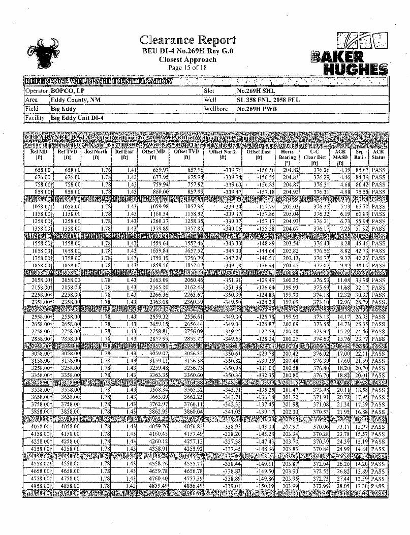
BEU DI-4 No.269H Rev G.O Closest Approach
Page 15 of 18
mmm SMWWtMlHBIil^^ • '• , Operator BOPCO, LP Slot No.269H SHL Area Eddy County, NM Well SL 358 FNL, 2058 F E L Field Big Eddy Wellbore No.269H PWB Facility Big Eddy Unit DI-4
Ref MD [ft]
Ref TVD [ftl
W H H i " ACR
Status
658.00 658.00 1.76 1.41 659.97 657.96 -339.76 -156.50 204.82 376.26 4.39, 85.67 PASS 676.00 676.00 1.78 1.43 677.95 675.94 -339.74 -156.55 204.83 376.29 4.46 84.39, PASS
758.00f 758.00 1.78 1.43 759.94 757.92 -339.63, -156.83 204.87 376.31 4.68 80.42 PASS 1.43 860.00 857.99 339.47 204.93
M 376.31 4.98 75.55 PASS
mmm 1058.00f 1058.00 1.78 1.43 1059.98 1057.96 -339.24 -157.79 205.03 376.35 5.73 65.70 PASS 1158.00+ 1158.00 .78 1.43 1160.34 1158.32 -339.17 -157.86 205.04 376.32 6.19 60.80 PASS 1258.00f 1258.00 1.78 1.43 1260.37 1258.35 -339.37 -157.17 204.93 376.21 6.73. 55.94, PASS 1358.00 1358.00 .78 1.43
sj ; • • "§ 204.67 _ 376.17
1558.00; 1558.00 1.78 1.43 1559.64 1557.46 -343.33 -148.89 203.54 376.43 8.28 45.46 PASS 1658.00 1658.00 1.78 1.43 1659.8 1657.52 -345.30 -144.64 202.82 376.56 8.82 42.70 PASS 1758.00 1758.00 1.78 1.43 1759.19 1756.79 -347.24 -140.51 202.13 376.77 9.37 40.23 PASS 1858.00 1858.00 .78 .43 1859.56
wmm 1857.07 -349.18 136.44 201.45 377.07 9.92
WM 38.00 PASS
sra 2058.00 2058.00 .78 1.43 2063.09 2060.46 -351.3 -129.49 200.35 376.59 11.08 33.98 PASS 2158.00 2158.00 1.78 1.43 2165.10 2162.43 -351.38 -126.64 199.93 375.69 11.68, 32.17 PASS 2258.00f 2258.00 1.78 1.43 2266.36 2263.67 2358.00 1.78 1.43 2363.08 2360.39
-350.39 -3 49.50
-124.89 199.73 374.18 12.32 30.37 PASS 199.69
mmm. 28.79 PASS
2558.00 2558.00 1.78 .43 2559.32 2556.61 -349.00 -125.78 199.93 373.13 14.17 26.33 PASS 2658.00- 2658.00 1.78 1.43 2659.15 2656.44 -349.04 -126.87 200.09 373.55 14.73 25.35 PASS 2758,00} 2758.00 1.78 1.43. 2758.81 2756.09 -349.22 -127.59 200.18 373.97 15.29. 24.46 PASS 2858.00 2858.00 2855.27 -349.65 -128.24 200 25 374.60 15.76, 23.77 PASS
mam ass mi mm 3058.00}, 3058.00 1.78 1.43 3059.07 3056.35 -350.61 -129.78 200.42 376.02 17.00 22.11 PASS 3158.00t 3158.00 1.78 1.43 3159.1 3156.38 -350.82 -130.25 200.48 376.39 17.60 21.39 PASS 3258.00} 3258.00 1.78 1.43 3259.48 3256.75 -350.98 -131.00 200.58 376.80 18.20 20.70 PASS 3358.00+ 1.78 1.43 3360.60
mskmmm .200 80 18.82 20.01 PASS
pffS&OOl mm 3558.00} 3558.00 1.78 1.43 3568.34 3565.52 -345.71 -135.25 201.47 373.48 20. 18.58 PASS 3658.00} 3658.00 .78 1.43 3665.09 3662.25 -343.71 -136.18 201.72 371.91 20.72 17.95 PASS 3758.00} 3758.00 .78 1.43 3762.97 3760.11 -342.33 -137.45 201.98 371.08 21.34 17.39 PASS 3858.00 3858.00 1.78 3862.93 3860.04
stmmm -341.03 -139.17
mm 370.53 202.30 21.95; 16.88
Wo PASS
mm ma 4058.00} 4058.00 1.78 .43 4059.76 4056.82 -338.93 -143.00 202.97 370.06 23.17, 15.97 PASS A 158.001 4158.00 1.78, 1.43 4160.45 4157.49 -338.20 -145.28 203.34 370.28 23.78 15.57 PASS 4258.001 4258.00 1.78 1.43 4260.12 4257.13 -337.38 -147.43 203.70 370.39 24.39 15.19. PASS 4358.00}. 4358.00 1.78 -337.45 370.84 24.99. 14.84
mmm PASS
11111 4558.00 4558.00 .78 1.43 4558.76 4555.77 -338.44 -149.1! 203.87 372.04 26.20 14.20 PASS 4658.001 4658.00 1.78 1.43 4659.78 4656.78 -338.83 -149.50 203.90 372.55 26.82 13.89 PASS 4758.00} 4758.00 1.78 1.43 4760.40 4757.39 -338.89 -149.86 203.95 372.75 27.44 13.59 PASS 4858.00
^958^0+, 4858.00 1.78 4859.49 -339.01 150.19 203.99 372.99 28 05; 13.30
I I I I PASS

BEU DI-4 No.269H Rev G.O Closest Approach
Page 16 of 18
S W W M M - : ,f ''.'* :::: ':;<*..•• : : * • { , r.'-:V:"-.f\;i ,V; Operator BOPCO, LP Slot No.269H SHL
Area Eddy County, N M Well SL 358 FNL, 2058 F E L
Field Big Eddy Wellbore No.269H PWB
Facility Big Eddy Unit DI-4
) Ref MD j Iftl
Ref TVD 101
Ref North [ft]
Ref East [ft]
Offset MD Iftl
Offset TVD [ft]
Offset North [ft]
Offset East [ft]
Horiz Bearing
[°1
C-C Clear Dist
[ft]
ACR MASD
[ft)
Sep Ratio
ACR Status
5058.00+ 5058.00 1.78 1.43 5059.20 5056.19 -339.50 -150.89 204.05 373.73 29311 12.75 PASS 5158.00f 5158.00 1.78 .1.43 5159.09 5156.09 -339.91 -151.23 204.07 . 374.24 29.95 12 sS PASS 5258.00f 5258.00 1.78 1.43 5260.05 5257.04 -340.32 -151.28 204.06 374.64 30.59 12.25 PASS 5358.001 5358.00 1.78 1.43 5360.57 5357.56 -340.73 -150.81 203.97 374:82 31.22 12.01 PASS
mmm V45>JJ0 J-. ,- ' :- ll?8 m i l 5558.00f 5558.00 1.78 1.43 5560.82 5557.81 -341.53 -149.42 203.72 374.99 32.45 11.56 PASS 5658.00f 5658.00 1.78 1.43 5661.33 5658.31 -341.86 -148.72 203.60 375.01 33.06 11.34 PASS 5758.00f 5758.00 1.78 1.43 5762.70 5759.68 -341.80 -148.06 203.51 374.70 33.67 11.13 PASS 5858£0f 5858/" 1.78 1.43
\ - - V I 43 5862.84 5859.82 -341.50 -147.55 203.46 374.22 34.26 10.92 •PASS 5858£0f 1.43
\ - - V I 43 7;-"-'=5#2l £kLltfe2 alii gp|ljj 6058.00| 6058.00 1.78 1.43 6063.23 . 6060.20 -340.62 -146.95 203.43 373.17 35.45 10.53 PASS 6158.00f 6158.00 1.78 1.43 6163.51 6160.48 -340.03 -146.71 203.43 372.54 36.06 10.33 PASS 6258.00+ 6258.00 1.78 1.43 6263.78 6260.75 -339.38 ' -146.45 203.44 371.84 36.67 10.14 PASS 6358.00| 6358.00 1.78 1.43 6364.07 6361.03 -338.64 -146.20 203.45 371.06 37.29 9.95 PASS
mmm mmm '•>'•- :fr"8 •V'' - 'jl':''3 • -mm mimm mm 3-f ,2l mm i S i 6558.00f 6558,00 1.78 1.43 6564.09 6561.05 -336.88 -146.19 203.55 369.44 38.54 9.59 PASS 6658.00+ 6658.00 1.78 1.43 6663.38 6660.34 -335.90 -146.56 203.671 368.69 39.17 9.41 PASS 6758.00t 6758.00 1.78 1.43 6764.71 6761.65 -334.80 -147.11 203.81 367.92 39.80 9.24 PASS 6858£0t, 6858 00 1.78 1.43 6866.42 6863.35 -333.29 -147.44 203.96 366.69 1 40.44 9.07 PASS 6858£0t,
. mm mmmm •.•••Mg§8l 7058.00+ 7058.00 1.78 1.43 7061.67 7058.60 -332.62 -146.61 203.88 365.70 41.69 8.77 PASS
7158.00| 7158.00 1.78 1.43 7163.02 7159.94 -332.74 -145.48 203.71 365.36 42.32 8.63 PASS 7258.00f 7258.00 1.78 1.43 7264.44 7261.35 -332.40 -144.26 203.56 364.57 42.96 8.49 PASS 7358.00| 7358.00 1.78 1.43 7363.22 7360.12 -332.10 -143.00 203.39 363.79 43.60 8.34 PASS
^ j 5 8 l j j L I L T S ' ttjj!jilli;2flj mm isiilil mm 7532.59 7532.59 1.78 1.43 '7534.57 7531.47 -332.52 ' -141.61 203.17 363.61 ' 44.67 8.14 PASS . 7558.00f 7557.99 1.59 1.96 7560.22 7557.12 -332.63 -141.51 203.23 363.72 44.83 8.11 PASS
7658.00f 7657.00 -2.76 14.33 7662.07 7658.97 -332.74 -141.26 205.24 364.82 45.44 8.03 PASS 7726.00f 7722.34 -8.96 31.93 7730.08 7726.97 -332.01 -141.20 208,19 366.54 45.97 7.97 PASS
mmm IS98 QMSSj 7858,001 7840.78 -28.10 86.27 7839.19 7836.07 -331.21 -140.70 216.83 378.70 46.93 8.07 PASS 7958.00f 7919.97 . -48.31 143.67 7899.08 7895.82 -334.89 -139.74 224.68 403.77 47.84 8.44 PASS 8058.00f 7987.39 -72.79 213.17 7950.72 7946.93 -342.17 -138.61 232.56 444.92 48.92 9.10 PASS 8158.00j 8041.00 -100.78 292.66 79.94.92 7990.11 -351.48 -137.63 239.77 500.59 50.07 10.00 PASS
,t:8232.'59r1 mm$m mmm SPM58 mmm $MM 'i?ASS:| • 8258.00f 8079.68 -131.38 379.54 8028.99 8023.00 -360.34 -136.82 246.'09 567.68 51.13 11.10 PASS
8358.001 8113.89 -162.59 468.17 8057.32 8050.04 -368.80 -136.43 251.17 641.98 51.99 12.35 PASS 8432.59 8139.40 -185.87 534.29 8080.01 8071.47 -376.23 -136.36 254.15 700.44 52.55 13.33 PASS 8458.00f 8147.87 -193.60 556.96 8088.28 8079.25 -379.05 -136.36 255.03 720.97 52.74 13.67 PASS
mmmm [iMiii 8658.00f 8198.55 -239.63 744.49 8131.43 8119.52 -394.52 -136.73 260.03 898.20 53.85 16.68 PASS 8758.00+ 8212.83 -252.43 842.58 8143.24 8130.45 -398.99 -136.95 261.49 993.86 54.20 18.34 PASS 8858.00+ 8219.51 -258.19 942.15 8147.79 8134.65 -400.75 -137.04 1 262.48 1091.87 54.41 20.07 PASS 8888.96 8220.01 -258.54 973.11 8147.75 8134.61 ' -400.73 -137.04 262.70 1122.47 54.46 20.61 PASS
»:";8958'.o.o:+; mmm mmmm mmmm
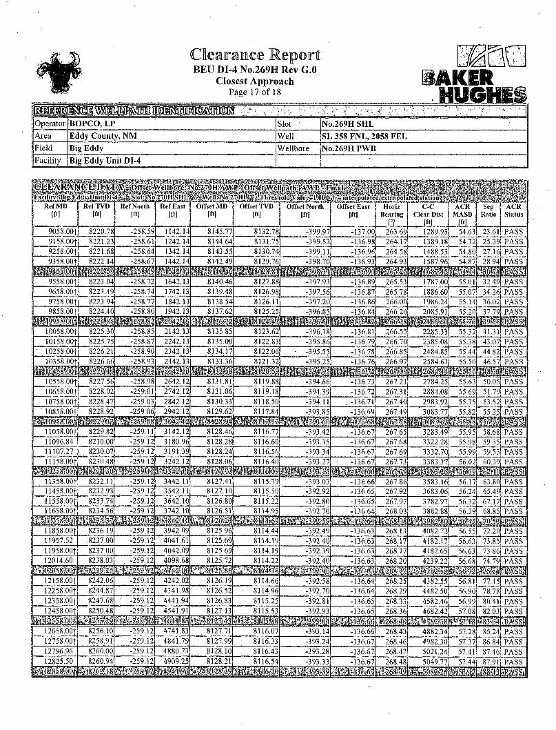
Clearance Report BEU DI-4 No.269H Rev G.O
Closest Approach Page 17 of 18
Operator BOPCO, LP jsiot No.269H SHL Area Eddy County, NM jWell SL 358 FNL, 2058 FEL Field Big Eddy (Wellbore No.269H PWB Facility Big Eddy Unit DI-4 j
9058.00f 8220.78 -258.59 1142.14 8145.77 8132.78 399.97 -137.00 263.69 1289.93 54.63 23.61 PASS 9158.00| 8221.23 -258.61 1242.14 8144.64 8131.75 -399.53 -136.98 264.17 1389.18 54.72 25.39 PASS 9258.00f 8221.68 -258.64 1342.14 8143.55 8130.74 -399.1 -136.96 264.58 1488.53 54.80 27.16 PASS 9358.001 8222.14 -258:67 1442.14 8142.49 8129.76 -398.70 264.93 1587.96 54.87
vm 28.94 PASS
111 mm 9558. OOf 8223.04 -258.72 1642.13 8140.46 8127.88 -397.93 -136.89 265.53 1787.00 55.01 32.49 PASS 9658.00+ 8223.49 -258.74 1742.13: 8139.48 8126.98 -397.56 -136.87 265.78 1886.60 55.07 34.26 PASS 9758.001 8223.94 -258.77 1842.13 8138.54 8126.11 -397.20 -136.86 266.00 1986.24 55.14 36.02 PASS
10058.00+ 8225.30 -258.85 2142.13 8135.85 8123.62 -396.18 -136.81 266.55 2285.33 55.32 41.3:
PASS
l l l l PASS
10158.OOf 8225.75 -258.87 2242.13 8135.00 8122.83 -395.86 -136.79 266.70 2385.08 55.38 43.07 PASS 10258.00f 8226.21 -258.90 2342.13 8134.17 8122.06 -395.55. -136.78 266.85, 2484.85 55.44 44.82 PASS 10358.00+ 8226.66 -258.93 8133.36 8121.32 36.76
it 266.97 2584 63 55.50
mm 46.57 PASS
i 10558.00f 8227.56 -258.98 2642.12 8131.81 8119.88 -394.66 -136.73 267.21 2784.25 55.63 50.05 PASS 10658.00+ 8228.02 -259.01 2742.12 8131.06 8119.18 -394.39 -136.72 267.31 2884.08 55.69 51.79 PASS 10758.OOf 8228.47 -259.03 2842.12 8130.33 8118.50 -394.1 -136.71 267.40 2983.92 55.75 53.52 PASS
-259.06 2942.12 8129.62 8117.84 -393.85
mmm 136.69 267.49 3083.77 55.82 55.25
mm PASS
I1058.00f 8229.82 -259.11 3142.12 8128.46 8116,77 -393.42 -136.67 267.65 3283.49 55.95 58.68 PASS 11096.84 8230.00 -259.12 3180.96 8128.28 8116.60 -393.35 -136.67 267.68 3322.28 55.98 59.35 PASS
1107.27 8230.07 -259.12 3191.39 8128.24 8116.56 -393.34 -136.67 267.69 3332.70 55.99 59.53 PASS 8230.48 -259.12 3242 12
mwmM 8128.06 8116.40 -393.27 267.73: 56.02 60.39 PASS
IfsH 11358.00f 8232.11 -259.12 3442.11 8127.41 8115.79 -393.03 -136.66 267.86 3583.16 56.17 63.80 PASS 11458.OOf 8232.93 -259.12 3542. 8127.10 8115.50 -392.92 -136.65 267.92 3683.06 56.24 65.49 PASS
1558.00f 8233.74 -259.12 3642.10 8126.80 8115.22 -392.80 -136.65 267.97 3782.97 56.32 67.17 PASS 11658.001 -259.12 -392.70 26803 56.39 68.85 PASS
B H »s.s;,; 11858.00f 8236.19 -259.12 3942.09i 8125.96 8114.44 -392.49 -136.63 268.13 4082.72 56.55 72.20 PASS 11957.52 .8237.00 -259.12 . 4041.61 8125.69 8114.19 -392.40 -136.63 268.17 .4182.17 56.63 73.85 PASS 11958.00f 8237.00 -259.12 4042.09 8125.69 8114.19 -392.39 -136.63 268:17 4182.65 56.63 73.86 PASS 12014.60 8238 03 -259.12
kmmm 4098.68 8125.72 8114.22
, 9 K r i fe -392.40 136.63
111 268.20 4239.22 56.68 74.79 PASS
p a 12158.00f 8242.06 -259.12 4242.02 8126.19 8114.66 -392.58 -136.64 268.25 4382.55 56.81 77.15 PASS 12258.00+ 8244.87 -259.12 4341.98 8126.52 8114.96 -392.70 -136.64 268.29 4482.50 56.90 78.78 PASS 12358.00f 8247.68 -259.12 4441.94 8126.83 8115.25 -392.81 -136.65 268.33 4582.46 56.99 80.41 PASS 1245 8. OOf 8250.48 -259.12 4541.91
mW$4 812713:
K*! 8W2S4g 8115.53 -392.93
M s -136.65, 268.36 4682.42 57.08 82.03 PASS
mm 12658-00f_ 8256.10 -259.12 4741.83 8127.71 8116.07 -393.14 -136.66 268.43 4882.34 57.28 85.24 PASS_ PASS 12758.00f 8258.91 -259.12 4841.79 8127.99 8116.33 -393.24 -136.67 268.46 4982.30 57.37
12796.96 8260.00 -259.12 4880.73 8128.10 8116.43 -393.28 -136.67 268.47 5021.24 57.41 87.46 PASS 12825.50
g#il8l8l l) | 8260.94 -259.12 8128.21 8116.54 -393.33 268.48 5049.77 57.44 87.91 PASS
l l l l l l l l l tesstn

BEU DI-4 No.269H Rev G.O Closest Approach
Page 18 of 18 BAKER
, i , . ' . . . . . , * l rf' . : i Operator BOPCO, LP Slot No.269HSHL
Area Eddy County, N M Well SL 358 FNL, 2058 F E L
Field Big Eddy Wellbore No.269H PWB
Facility Big Eddy Unit DI-4
Ref MD j Ref TVD [ft] [ft]
Ref North Ift]
Ref East [ft]
Offset MD [ft]
Offset TVD [ft]
Offset North [ft]
Offset East [ft]
Horiz Bearing
1°1
C-C Clear Dist
1ft]
ACR MASD
[ftl
Sep Ratio
ACR Status
12958.001 8265.98 -259.12 5041.66 8128.91 8117.18 -393.58 -136.68 268.51 5182.22 57758" 90.00 PASS 13058.00| 8269.79 -259.12 5141.59 8129.64 8117.86 . -393.86 -136.69 268.54 5282.19 57.68 91.57 PASS 13158.001 8273.59 -259.12 5241.52 8130.41 8118.58 -394.14 -136.71 268.56 5382.15 57.79 93.13 PASS 13258.00+ 8277.39 -259.12 5341/ ' 8131.16 8119.28 -394.42 -136.72 268.59 5482.12 57.90 94.68 PASS
l i i m i H i mm mm i ^ 5 8 i i mm HHi 13458.00f 8285.00 -259.12 5541.30 8132.63 8120.63 -394.97 -136.75 268.63 5682.05 58.13 97.75 PASS 13558:00+ 8288.80 -259.12 564 n ? 8133.34 8121.29 -395.23 -136.76 268.65 . 5782.02 58.24 99.28 PASS 13658.00+ 8292.61 -259.12 5741.15 8134.03 8121.94 -395.50 -136.77 268.67 5881.9.8 58.36 100.79 PASS 13758.00t 8296.41 -259.12 584I.08| 8134.72 8122.57 -395.75 -136.79 268.69 5981.95 58.47 102.30 PASS
i f f i i i mm -'111 u f ^ : : 3 2 o i ! l H i wmmm mm 13958.00+ 8304.02 -259.12 6040.94 8136.05 8123.80 -396.25 -136.81 268.73 6181.90 58.71 105.29 PASS 14058.00f 8307.82 -259.12 6140.86 8136.69 8124.40 -396.50 -136.82 268.75 6281.87 58.83 106.77 PASS 14158.00+ 8311.62 -259.12 6240.79 8137.33 8124.99 -396.74 -136.83 268.76 6381.84 58.96 108.24 PASS 14258.00+ ' 8315.43 -259.12 6340.72 8137.95 8125:57 -396.97 -136.85 268.78 6481.81 59.08 109.71 PASS
m i mmm mmm •^«J2'2.1 M « « ^ i 6 5 . i i i ^59 .2 l | I M f s ' f 14458.00f 8323.03 -259.12 6540.57 8139.17 8126.69 -397.44 -136.87 268.81 6681.76 59.33 112.61 PASS 14558.00f 8326.84 -259.12 6640.50 8139.76 8127.24 -397.66 -136.88 268.83 6781.74 59.46 114.05 PASS 14658.00+ 8330.64 -259.12 6740.43 8140.34 8127.77 • -397.88 -136.89 268.84 6881.71 59.59 115.48 .PASS I4758.00f 8334.44 -259.12 6840.36 8140.91 8128.30 -398.10 -136.90 268.86 6981.69 59.72 116.90 PASS
mmm mm m . • - - • L , 8 ( i i « mmmm &mmm mm mmm mm 14904.15 8340.00 -259.12 6986.40 8141.73 8129.06 -398.41 -136.92 268.88 7127.80 59.92 118.96 PASS
mUm mmmm ^mmmm
Slot Surface Uncertainty @1SD Horizontal 0.100ft Vertical 0.100ft
Facility Surface Uncertainty @1SD Horizontal 3.300ft Vertical ' 1.000ft
f « I Start MD
[ft] End MD
[ft] Positional Uncertainty Model Log Name/Comment s Wellbore
29.00 7810.00 Generic gyro - northseeking (Standard) Gyrodata Gyro Surveys < 102 - 7810> No.270H AWP 7810.00 14657.00 NaviTrak (Standard) BHI NaviTrak <7848-14657> No.270H AWP
14657.00 14732.00 Blind Drilling (std) Projection to bit No.270H AWP
t
M D Reference: Rig on No.270H SHL (KB) \Offset TVD & local coordinates use Reference Wellpath settings \(See WELLPA TH DA TUM on page 1 of this report)
Ellipse Start M D {29.00ft
0
PECOS DISTRICT CONDITIONS OF APPROVAL
OPERATOR'S NAME BOPCO, L.P. LEASE NO. NMNM-04557
WELL NAME & NO. Big Eddy Unit DI4 269H SURFACE HOLE FOOTAGE 0358' FNL & 2058' FEL
BOTTOM HOLE FOOTAGE 0660' FNL & 0330' FEL Sec. 04, T. 20 S., R 31 E. LOCATION Section 05, T. 20 S., R 31 E., NMPM
COUNTY Eddy County, New Mexico API 30-015-42638
I . DRILLING
A. DRILLING OPERATIONS REQUIREMENTS
The BLM is to be notified in advance for a representative to witness:
a. Spudding well (minimum of 24 hours) b. Setting and/or Cementing of all casing strings (minimum of 4 hours) c. BOPE tests (minimum of 4 hours)
[X] Eddy County Call the Carlsbad Field Office, 620 East Greene St., Carlsbad, NM 88220, (575) 361-2822 '
1. Operator has state that Hydrogen Sulfide (H2S) monitors will be installed prior to drilling out the surface shoe. I f H2S is encountered in quantities greater than 10 PPM the well shall be shut in and H2S equipment shall be installed and flare line must be extended pursuant to Onshore Oil and Gas Order #6. Report measured values and formation to the BLM. After detection, the Hydrogen Sulfide area must meet Onshore Order 6 requirements, which includes equipment and personnel/public protection items.
f>
2. Operator shall sufficiently secure the wellbore prior to skidding the rig to the 27IH as stated by the operator.
3. Floor controls are required for 3M or Greater systems. These controls will be on the rig floor, unobstructed, readily accessible to the driller and will be operational at all times during drilling and/or completion activities. Rig floor is defined as the area immediately around the rotary table; the area immediately above the substructure on which the draw works is located, this does not include the dog house or stairway area,
Page 1 of 6

4. The record of the drilling rate along with the GR/N well log run from TD to surface (horizontal well - vertical portion of hole) shall be submitted to the BLM office as well as all other logs run on the borehole 30 days from completion. I f available, a digital copy of the logs is to be submitted in addition to the paper copies. The Rustler top and top and bottom of Salt are to be recorded on the Completion Report.
B. CASING
Changes to the approved APD casing program need prior approval if the items substituted are of lesser grade or different casing size or are Non-API. The Operator can exchange the components of the proposal with that of superior strength (i.e. changing from J-55 to N-80, or from 36# to-40#). Changes to the approved cement program need prior approval i f the altered cement plan has less volume or strength or if the changes are substantial (i.e. Multistage tool, ECP, etc.). The initial wellhead installed on the well will remain on the well with spools used as needed.
Centralizers required on surface casing per Onshore Order 2.III.B.l.f.
Wait on cement (WOC) time prior to drilling out for a primary cement job will be a minimum 18 hours for a water basin, 24 hours in the potash area, or 500 pounds compressive strength, whichever is greater for all casing strings. DURING THIS WOC TIME, NO DRILL PIPE, ETC. SHALL BE RUN IN THE HOLE. Provide compressive strengths including hours to reach required 500 pounds compressive strength prior to cementing each casing string. IF OPERATOR DOES NOT HAVE THE WELL SPECIFIC CEMENT DETAILS ONSITE PRIOR TO PUMPING THE CEMENT FOR EACH CASING STRING, THE WOC WILL BE 30 HOURS. See individual casing strings for details regarding lead cement slurry requirements.
No pea gravel permitted for remedial or fall back remedial without prior authorization from the BLM engineer.
Capitan Reef Secretary's Potash Possibility of water flows in the Artesia Group and Salado. Possibility of lost circulation in the Red Beds, Artesia Group, Rustler, Capitan Reef, and Delaware.
Page 2 of 6
1. The 16 inch surface casing shall be set at approximately 830 feet (a minimum of 25 feet into the Rustler Anhydrite and above the salt) and cemented to the surface. I f salt is encountered, set casing at least 25 feet above the salt.
a. If cement does not circulate to the surface, the appropriate BLM office shall be notified and a temperature survey utilizing an electronic type temperature survey with surface log readout will be used or a cement bond log shall be run to verify the top of the cement. Temperature survey will be run a minimum of six hours after pumping cement and ideally between 8-10 hours after completing the cement job.
b. Wait on cement (WOC) time for a primary cement job is to include the lead cement slurry.
c. Wait on cement (WOC) time for a remedial job will be a minimum of 4 hours after bringing cement to surface or 500 pounds compressive strength, whichever is greater.
d. If cement falls back, remedial cementing will be done prior to drilling out that string.
2. The minimum required fill of cement behind the 13-3/8 inch 1 s t intermediate casing, which shall be set at approximately 2700 feet (in the Seven Rivers formation), is:
3 Cement to surface. If cement does not circulate see B. 1 .a, c-d above. Wait on cement (WOC) time for a primary cement job is to include the lead cement slurry due to potash.
3. The minimum required fill of cement behind the 9-5/8 inch intermediate casing is:
Operator has proposed DV tool at depth of 2895', but will adjust cement proportionately if moved. DV tool shall be set a minimum of 50' below previous shoe and a minimum of 200' above current shoe. Operator shall submit sundry if DV tool depth cannot be set in this range. I f an ECP is used, it is to be set a minimum of 50' below the shoe to provide cement across the shoe. I f it cannot be set below the shoe, a CBL shall be run to verify cement coverage. •
a. First stage to DV tool:
2<j Cement to circulate. If cement does not circulate, contact the appropriate BLM office before proceeding with second stage cement job. Operator should have plans as to how they will achieve circulation on the next stage.
r
Page 3 of 6

b. Second stage above DV tool:
Cement to surface. If cement does not circulate see B. La, c-d above. Wait on cement (WOC) time for a primary cement job is to include the lead cement slurry due to potash and Capitan Reef. Excess calculates to 17% - Additional cement may be required.
Centralizers required through the curve and a minimum of one every other joint.
4. The minimum required fil l of cement behind the 5-1/2 inch production casing is:
Operator has proposed DV tool at depth of 5000', but will adjust cement proportionately if moved. DV tool shall be set a minimum of 50' below previous shoe and a minimum of 200' above current shoe. Operator shall submit sundry if DV tool depth cannot be set in this range.
a. First stage to DV tool:
K] Cement to circulate. If cement does not circulate, contact the appropriate . BLM office before proceeding with second stage cement job. Operator should have plans as to how they will achieve approved top of cement on the next stage.
b. Second stage above DV tool:
1X1 Cement should tie-back at least 50 feet above the Capitan Reef (Top of Capitan Reef estimated at 2804'). Operator shall provide method of verification. Wait on cement (WOC) time for a primary cement job is to include the lead cement slurry due to potash.
5. If hardband drill pipe is rotated inside casing, returns will be monitored for metal. If metal is found in samples, drill pipe will be pulled and rubber protectors which have a larger diameter than the tool joints of the drill pipe will be installed prior to continuing drilling operations.
C. PRESSURE CONTROL
1. All blowout preventer (BOP) and related equipment (BOPE) shall comply with well control requirements as described in Onshore Oil and Gas Order No. 2 and API RP 53 Sec. 17.
Page 4 of 6

2. Variance approved to use flex line from BOP to choke manifold. Check condition of flexible line from BOP to choke manifold, replace if exterior is damaged or i f line fails test. Line to be as straight as possible with no hard bends and is to be anchored according to Manufacturer's requirements. The flexible hose can be exchanged with a hose of equal size and equal or greater pressure rating. Anchor requirements, specification sheet and hydrostatic pressure test certification matching the hose in service, to be onsite for review. These documents shall be posted in the company man's trailer and on the rig floor. If the BLM inspector questions the straightness of the hose, a BLM engineer will be contacted and will review in the field or via picture supplied by inspector to determine i f changes are required (operator shall expect delays i f this occurs).
3. A variance is granted for the use of a diverter on the 20" surface casing.
4. Minimum working pressure of the blowout preventer (BOP) and related equipment (BOPE) required for drilling below the 13-3/8 1 s t intermediate casing shoe shall be 3000 (3M) psi.
5. The appropriate BLM office shall be notified a minimum of 4 hours in advance for a representative to witness the tests.
a. In potash areas, for all casing strings utilizing slips, these are to be set as soon as the crew and rig are ready and any fallback cement remediation has been done. For all casing strings, casing cut-off and BOP installation can be initiated at twelve hours after bumping the plug. However, no tests shall commence until the cement has had a minimum of 24 hours setup time.
b. The tests shall be done by an independent service company utilizing a test plug not a cup or J-packer.
c. The test shall be run on a 5000 psi chart for a 2-3M BOP/BOP, on a 10000 psi chart for a 5M BOP/BOPE and on a 15000 psi chart for a 10M BOP/BOPE. If a linear chart is used, it shall be a one hour chart. A circular chart shall have a maximum 2 hour clock. If a twelve hour or twenty-four hour chart is used, tester shall make a notation that it is run with a two hour clock.
d. The results of the test shall be reported to the appropriate BLM office.
e. All tests are required to be recorded on a calibrated test chart. A copy of the BOP/BOPE test chart and a copy of independent service company test will be submitted to the appropriate BLM office.
f. The BOP/BOPE test shall include a low pressure test from 250 to 300 psi. The test will be held for a minimum of 10 minutes if test is done with a test plug and 30 minutes without a test plug. This test shall be performed prior to the test at full stack pressure.
Page 5 of 6
D. DRILL STEM TEST
If drill stem tests are performed, Onshore Order 2.III.D shall be followed.
E. WASTE MATERIAL AND FLUIDS
All waste (i.e. drilling fluids, trash, salts, chemicals, sewage, gray water, etc.) created as a result of drilling operations and completion operations shall be safely contained and disposed of properly at a waste disposal facility. No waste material or fluid shall be disposed of on the well location or surrounding area.
Porto-johns and trash containers will be on-location during fracturing operations or any other crew-intensive operations.
JAM 111914
Page 6 of 6
Related Documents