2550 Garcia Avenue Mountain View, CA 94043 U.S.A. Addendum for SMCC Hardware SunDiag User’s Guide Part No: 801-7263-10 Revision A, November 1994 A Sun Microsystems, Inc. Business

Welcome message from author
This document is posted to help you gain knowledge. Please leave a comment to let me know what you think about it! Share it to your friends and learn new things together.
Transcript

2550 Garcia AvenueMountain View, CA 94043U.S.A.
Addendum for SMCC Hardware
SunDiag User’s Guide
Part No: 801-7263-10Revision A, November 1994
A Sun Microsystems, Inc. Business2550 Garcia AvenueMountain View, CA 94043 U.S.A.415 960-1300 FAX 415 969-9131
PleaseRecycle
1994 Sun Microsystems, Inc.2550 Garcia Avenue, Mountain View, California 94043-1100 U.S.A.
All rights reserved. This product and related documentation are protected by copyright and distributed under licensesrestricting its use, copying, distribution, and decompilation. No part of this product or related documentation may bereproduced in any form by any means without prior written authorization of Sun and its licensors, if any.
Portions of this product may be derived from the UNIX® and Berkeley 4.3 BSD systems, licensed from UNIX SystemLaboratories, Inc., a wholly owned subsidiary of Novell, Inc., and the University of California, respectively. Third-party fontsoftware in this product is protected by copyright and licensed from Sun’s font suppliers.
RESTRICTED RIGHTS LEGEND: Use, duplication, or disclosure by the United States Government is subject to the restrictionsset forth in DFARS 252.227-7013 (c)(1)(ii) and FAR 52.227-19.
The product described in this manual may be protected by one or more U.S. patents, foreign patents, or pending applications.
TRADEMARKSSun, the Sun logo, Sun Microsystems, Sun Microsystems Computer Corporation, Solaris, are trademarks or registeredtrademarks of Sun Microsystems, Inc. in the U.S. and certain other countries. UNIX is a registered trademark of Novell, Inc., inthe United States and other countries; X/Open Company, Ltd., is the exclusive licensor of such trademark. OPEN LOOK® is aregistered trademark of Novell, Inc. PostScript and Display PostScript are trademarks of Adobe Systems, Inc. All otherproduct names mentioned herein are the trademarks of their respective owners.
All SPARC trademarks, including the SCD Compliant Logo, are trademarks or registered trademarks of SPARC International,Inc. SPARCstation, SPARCserver, SPARCengine, SPARCstorage, SPARCware, SPARCcenter, SPARCclassic, SPARCcluster,SPARCdesign, SPARC811, SPARCprinter, UltraSPARC, microSPARC, SPARCworks, and SPARCompiler are licensedexclusively to Sun Microsystems, Inc. Products bearing SPARC trademarks are based upon an architecture developed by SunMicrosystems, Inc.
The OPEN LOOKand Sun™ Graphical User Interfaces were developed by Sun Microsystems, Inc. for its users and licensees.Sun acknowledges the pioneering efforts of Xerox in researching and developing the concept of visual or graphical userinterfaces for the computer industry. Sun holds a non-exclusive license from Xerox to the Xerox Graphical User Interface,which license also covers Sun’s licensees who implement OPEN LOOK GUIs and otherwise comply with Sun’s written licenseagreements.
X Window System is a product of the Massachusetts Institute of Technology.
THIS PUBLICATION IS PROVIDED “AS IS” WITHOUT WARRANTY OF ANY KIND, EITHER EXPRESS OR IMPLIED,INCLUDING, BUT NOT LIMITED TO, THE IMPLIED WARRANTIES OF MERCHANTABILITY, FITNESS FOR APARTICULAR PURPOSE, OR NON-INFRINGEMENT.
THIS PUBLICATION COULD INCLUDE TECHNICAL INACCURACIES OR TYPOGRAPHICAL ERRORS. CHANGES AREPERIODICALLY ADDED TO THE INFORMATION HEREIN; THESE CHANGES WILL BE INCORPORATED IN NEWEDITIONS OF THE PUBLICATION. SUN MICROSYSTEMS, INC. MAY MAKE IMPROVEMENTS AND/OR CHANGES INTHE PRODUCT(S) AND/OR THE PROGRAM(S) DESCRIBED IN THIS PUBLICATION AT ANY TIME.

iii
Contents
Preface . . . . . . . . . . . . . . . . . . . . . . . . . . . . . . . . . . . . . . . . . . . . . . . xv
1. Overview . . . . . . . . . . . . . . . . . . . . . . . . . . . . . . . . . . . . . . . . . . . . 1-1
1.1 About This Book . . . . . . . . . . . . . . . . . . . . . . . . . . . . . . . . . . 1-1
1.2 What’s New in Version 4.4 . . . . . . . . . . . . . . . . . . . . . . . . . 1-1
1.3 Solaris Issues . . . . . . . . . . . . . . . . . . . . . . . . . . . . . . . . . . . . . 1-2
1.4 Displaying the POST Log File on Sun-4m Systems . . . . . 1-3
1.5 Overrun/Underrun Diskette Test Errors. . . . . . . . . . . . . . 1-4
1.6 Running cdtest with an Operating System CD-ROM . 1-6
2. CPU Test Descriptions . . . . . . . . . . . . . . . . . . . . . . . . . . . . . . . . . 2-1
2.1 Sun Multimedia Codec Test (audbri ) . . . . . . . . . . . . . . . 2-2
2.1.1 audbri Test Descriptions . . . . . . . . . . . . . . . . . . . . . 2-2
2.1.2 audbri Option Menus. . . . . . . . . . . . . . . . . . . . . . . . 2-4
2.1.3 audbri Command Line Syntax . . . . . . . . . . . . . . . . 2-7
2.1.4 audbri Quick Test Description . . . . . . . . . . . . . . . . 2-8
2.2 ISDN/DBRI Test (isdntest ) . . . . . . . . . . . . . . . . . . . . . . . 2-9
iv SunDiag User’s Guide: Addendum for SMCC Hardware—November 1994
2.2.1 isdntest Test Description . . . . . . . . . . . . . . . . . . . . 2-9
2.2.2 isdntest Options . . . . . . . . . . . . . . . . . . . . . . . . . . . 2-12
2.2.3 isdntest Command Line Syntax . . . . . . . . . . . . . . 2-13
2.2.4 isdntest Quick Test Description . . . . . . . . . . . . . . 2-13
2.2.5 isdntest Error Messages. . . . . . . . . . . . . . . . . . . . . 2-14
2.3 Graphics Tower (gttest ) . . . . . . . . . . . . . . . . . . . . . . . . . . 2-15
2.3.1 gttest Test Description . . . . . . . . . . . . . . . . . . . . . . 2-17
2.3.2 gttest Command Line Syntax . . . . . . . . . . . . . . . . 2-23
2.3.3 gttest Quick Test Description . . . . . . . . . . . . . . . . 2-24
2.3.4 gttest Command Line Examples . . . . . . . . . . . . . . 2-24
2.3.5 gttest Error Messages . . . . . . . . . . . . . . . . . . . . . . . 2-25
2.4 cgsix Frame Buffer, GX and GX+ Options Test (cg6test ) 2-33
2.4.1 cg6test Test Description.. . . . . . . . . . . . . . . . . . . . . 2-33
2.4.2 cg6test Options . . . . . . . . . . . . . . . . . . . . . . . . . . . . 2-35
2.4.3 cg6test Command Line Syntax . . . . . . . . . . . . . . . 2-35
2.4.4 cg6test Quick Test Description . . . . . . . . . . . . . . . 2-35
2.4.5 cg6test Error Messages . . . . . . . . . . . . . . . . . . . . . . 2-36
2.5 cgtwelve Frame Buffer, GS Test (cg12 ) . . . . . . . . . . . . . . . 2-38
2.5.1 cg12 Test Description . . . . . . . . . . . . . . . . . . . . . . . . 2-38
2.5.2 cg12 Options. . . . . . . . . . . . . . . . . . . . . . . . . . . . . . . . 2-41
2.5.3 cg12 Command Line Syntax. . . . . . . . . . . . . . . . . . . 2-43
2.5.4 cg12 Quick Test Description . . . . . . . . . . . . . . . . . . . 2-44
2.5.5 cg12 Error Messages . . . . . . . . . . . . . . . . . . . . . . . . . 2-44
2.6 Color Graphics Frame Buffer Test (cg14test ) . . . . . . . . 2-46

Contents v
2.6.1 cg14test Test Description . . . . . . . . . . . . . . . . . . . . 2-46
2.6.2 cg14test Options . . . . . . . . . . . . . . . . . . . . . . . . . . . 2-54
2.6.3 cg14test Command Line Syntax . . . . . . . . . . . . . . 2-55
2.6.4 cg14test Quick Test Description . . . . . . . . . . . . . . 2-55
2.6.5 cg14test Error Messages. . . . . . . . . . . . . . . . . . . . . 2-55
2.7 Pixel Processor Test (sxtest ) . . . . . . . . . . . . . . . . . . . . . . 2-63
2.7.1 sxtest Description . . . . . . . . . . . . . . . . . . . . . . . . . . 2-63
2.7.2 sxtest Options . . . . . . . . . . . . . . . . . . . . . . . . . . . . . 2-64
2.7.3 sxtest Module Descriptions . . . . . . . . . . . . . . . . . . 2-65
2.7.4 sxtest Command Line Syntax . . . . . . . . . . . . . . . . 2-77
2.7.5 sxtest Quick Test Description . . . . . . . . . . . . . . . . 2-78
2.7.6 sxtest .usertest Example . . . . . . . . . . . . . . . . . 2-78
2.7.7 sxtest Error Messages . . . . . . . . . . . . . . . . . . . . . . . 2-78
2.8 S24 Frame Buffer Test (tcxtest ) . . . . . . . . . . . . . . . . . . . . 2-80
2.8.1 tcxtest Test Descriptions . . . . . . . . . . . . . . . . . . . . 2-80
2.8.2 tcxtest Options . . . . . . . . . . . . . . . . . . . . . . . . . . . . 2-83
2.8.3 tcxtest Command Line Syntax . . . . . . . . . . . . . . . 2-84
3. SBus Test Descriptions. . . . . . . . . . . . . . . . . . . . . . . . . . . . . . . . . 3-1
3.1 SBus Printer Card Tests (lpvitest and bpptest ). . . . . 3-2
3.1.1 Printer Test Hardware and Software Requirements 3-2
3.1.2 lpvitest Test Description . . . . . . . . . . . . . . . . . . . . 3-2
3.1.3 lpvitest Options . . . . . . . . . . . . . . . . . . . . . . . . . . . 3-3
3.1.4 lpvitest Command Line Syntax . . . . . . . . . . . . . . 3-4
3.1.5 lpvitest Quick Test Description . . . . . . . . . . . . . . 3-5

vi SunDiag User’s Guide: Addendum for SMCC Hardware—November 1994
3.1.6 bpptest Test Description . . . . . . . . . . . . . . . . . . . . . 3-5
3.1.7 bpptest Options . . . . . . . . . . . . . . . . . . . . . . . . . . . . 3-6
3.1.8 bpptest Command Line Syntax . . . . . . . . . . . . . . . 3-7
3.1.9 bpptest Quick Test Description . . . . . . . . . . . . . . . 3-7
3.1.10 Error Messages . . . . . . . . . . . . . . . . . . . . . . . . . . . . . . 3-7
3.2 SBus Expansion Subsystem (xbtest ) . . . . . . . . . . . . . . . . 3-8
3.2.1 xbtest Test Description . . . . . . . . . . . . . . . . . . . . . . 3-8
3.2.2 xbtest Configurations . . . . . . . . . . . . . . . . . . . . . . . 3-10
3.2.3 xbtest Options . . . . . . . . . . . . . . . . . . . . . . . . . . . . . 3-10
3.2.4 xbtest Command Line Syntax . . . . . . . . . . . . . . . . 3-11
3.2.5 xbtest Quick Test Description . . . . . . . . . . . . . . . . 3-11
3.2.6 xbtest .usertest File Example . . . . . . . . . . . . . . 3-12
3.2.7 xbtest Error Messages . . . . . . . . . . . . . . . . . . . . . . . 3-12
3.3 HSI/S Boards Test (sunlink ). . . . . . . . . . . . . . . . . . . . . . . 3-14
3.3.1 sunlink Test Description . . . . . . . . . . . . . . . . . . . . . 3-14
3.3.2 sunlink Configurations . . . . . . . . . . . . . . . . . . . . . . 3-14
3.3.3 sunlink Options . . . . . . . . . . . . . . . . . . . . . . . . . . . . 3-15
3.3.4 sunlink Command Line Syntax . . . . . . . . . . . . . . . 3-16
3.3.5 sunlink Quick Test Description . . . . . . . . . . . . . . . 3-17
3.3.6 sunlink Loopback Connectors . . . . . . . . . . . . . . . . 3-17
3.4 Prestoserve Test (pstest ) . . . . . . . . . . . . . . . . . . . . . . . . . . 3-18
3.4.1 pstest Test Description . . . . . . . . . . . . . . . . . . . . . . 3-18
3.4.2 pstest Command Line Syntax . . . . . . . . . . . . . . . . 3-19
3.4.3 pstest Quick Test Description . . . . . . . . . . . . . . . . 3-19

Contents vii
3.5 Serial Parallel Controller Test (spiftest ) . . . . . . . . . . . . 3-20
3.5.1 spiftest Hardware Requirements. . . . . . . . . . . . . 3-20
3.5.2 spiftest Configurations . . . . . . . . . . . . . . . . . . . . . 3-22
3.5.3 spiftest Options . . . . . . . . . . . . . . . . . . . . . . . . . . . 3-22
3.5.4 spiftest Command Line Syntax . . . . . . . . . . . . . . 3-24
3.5.5 spiftest Quick Test Option . . . . . . . . . . . . . . . . . . 3-26
3.5.6 spiftest Error Messages. . . . . . . . . . . . . . . . . . . . . 3-26
3.6 ZX Graphics Accelerator Test (leotest ) . . . . . . . . . . . . . 3-30
3.6.1 leotest Test Description . . . . . . . . . . . . . . . . . . . . . 3-32
3.6.2 leotest Command Line Syntax . . . . . . . . . . . . . . . 3-36
3.6.3 leotest Quick Test Description . . . . . . . . . . . . . . . 3-37
3.6.4 leotest Command Line Examples. . . . . . . . . . . . . 3-37
3.6.5 leotest Error Messages . . . . . . . . . . . . . . . . . . . . . . 3-38
3.7 NeWSprinter Test (spdtest ) . . . . . . . . . . . . . . . . . . . . . . . 3-45
3.7.1 spdtest Description . . . . . . . . . . . . . . . . . . . . . . . . . 3-45
3.7.2 spdtest Options . . . . . . . . . . . . . . . . . . . . . . . . . . . . 3-45
3.7.3 spdtest Command Line Syntax . . . . . . . . . . . . . . . 3-47
3.8 SunVideo Test (rtvctest ) . . . . . . . . . . . . . . . . . . . . . . . . . 3-48
3.8.1 rtvctest Test Description . . . . . . . . . . . . . . . . . . . . 3-48
3.8.2 rtvctest Options . . . . . . . . . . . . . . . . . . . . . . . . . . . 3-50
3.8.3 rtvctest Command Line Syntax . . . . . . . . . . . . . . 3-52
3.8.4 rtvctest Quick Test Description . . . . . . . . . . . . . . 3-52
3.8.5 rtvctest Error Messages. . . . . . . . . . . . . . . . . . . . . 3-52
3.9 PCMCIA Modem Card Test (pcmciatest ) . . . . . . . . . . . 3-57

viii SunDiag User’s Guide: Addendum for SMCC Hardware—November 1994
3.9.1 pcmciatest Test Description. . . . . . . . . . . . . . . . . . 3-57
3.9.2 pcmciatest Options. . . . . . . . . . . . . . . . . . . . . . . . . 3-58
3.9.3 pcmciatest Command Line Syntax. . . . . . . . . . . . 3-59
3.10 Infrared Interface Test (irtest ) . . . . . . . . . . . . . . . . . . . . 3-59
3.10.1 irtest Test Description . . . . . . . . . . . . . . . . . . . . . . 3-59
3.10.2 irtest Options . . . . . . . . . . . . . . . . . . . . . . . . . . . . . 3-60
3.10.3 irtest Command Line Syntax . . . . . . . . . . . . . . . . 3-60
3.11 SPARCstorage Array Controller Test (plntest ) . . . . . . . . . 3-61
3.11.1 plntest Test Description . . . . . . . . . . . . . . . . . . . . . 3-61
3.11.2 plntest Options . . . . . . . . . . . . . . . . . . . . . . . . . . . . 3-62
3.11.3 plntest Command Arguments. . . . . . . . . . . . . . . . 3-63
3.11.4 plntest Quick Test Description . . . . . . . . . . . . . . . 3-65
3.11.5 plntest .usertest File Command Line . . . . . . . 3-65
3.11.6 plntest Error Messages . . . . . . . . . . . . . . . . . . . . . . 3-65
4. User Test Descriptions . . . . . . . . . . . . . . . . . . . . . . . . . . . . . . . . . 4-1
4.1 SunDials Test (sundials ). . . . . . . . . . . . . . . . . . . . . . . . . . 4-2
4.1.1 sundials Test Description . . . . . . . . . . . . . . . . . . . . 4-2
4.1.2 sundials Command Line Syntax . . . . . . . . . . . . . . 4-2
4.1.3 sundials Quick Test Description . . . . . . . . . . . . . . 4-2
4.1.4 sundials Error Messages. . . . . . . . . . . . . . . . . . . . . 4-4
4.2 SunButtons Test (sunbuttons ) . . . . . . . . . . . . . . . . . . . . . 4-5
4.2.1 sunbuttons Test Description. . . . . . . . . . . . . . . . . . 4-5
4.2.2 sunbuttons Command Line Syntax. . . . . . . . . . . . 4-5
4.2.3 sunbuttons Quick Test Description . . . . . . . . . . . . 4-5

Contents ix
4.2.4 sunbuttons Error Messages . . . . . . . . . . . . . . . . . . 4-7
A. Loopback Connectors. . . . . . . . . . . . . . . . . . . . . . . . . . . . . . . . . . A-1
A.1 96-Pin Loopback Connector . . . . . . . . . . . . . . . . . . . . . . . . A-2
A.2 96-Pin Loopback Connector . . . . . . . . . . . . . . . . . . . . . . . . A-3
A.3 37-Pin RS-449 Loopback Cable . . . . . . . . . . . . . . . . . . . . . . A-4
A.4 37-Pin RS-449 Loopback Plug . . . . . . . . . . . . . . . . . . . . . . . A-5
A.5 9-pin Single-port Loopback Plug . . . . . . . . . . . . . . . . . . . . A-6
A.6 9-pin Single-port Loopback Plug . . . . . . . . . . . . . . . . . . . . A-7
A.7 9-Pin to 25-Pin Port-to-Port Loopback Cable . . . . . . . . . . A-8
A.8 9-Pin to 9-Pin Port-to-Port Loopback Cable . . . . . . . . . . . A-9
A.9 NT to TE Loopback Cable . . . . . . . . . . . . . . . . . . . . . . . . . . A-9

x SunDiag User’s Guide: Addendum for SMCC Hardware—November 1994

xi
Figures
Figure 1-1 Log Files Menu With POST Msgs Option . . . . . . . . . . . . . . . . . 1-3
Figure 1-2 SunDiag POST Message System Report. . . . . . . . . . . . . . . . . . . 1-3
Figure 1-3 Selecting SunOS from the cdtest Option Menu. . . . . . . . . . . 1-6
Figure 2-1 audbri Options Menu with a SpeakerBox Attached . . . . . . . 2-4
Figure 2-2 audbri Option Menu for a SPARCstation 5 . . . . . . . . . . . . . . 2-5
Figure 2-3 audbri Option Menu for a SPARCstation LX . . . . . . . . . . . . . 2-6
Figure 2-4 isdntest Local Loopback Subtest . . . . . . . . . . . . . . . . . . . . . . 2-9
Figure 2-5 isdntest Remote Loopback Subtest . . . . . . . . . . . . . . . . . . . . 2-10
Figure 2-6 isdntest Read/Write Subtest . . . . . . . . . . . . . . . . . . . . . . . . . 2-11
Figure 2-7 isdntest Data Path Subtest . . . . . . . . . . . . . . . . . . . . . . . . . . . 2-12
Figure 2-8 isdntest Options Menu . . . . . . . . . . . . . . . . . . . . . . . . . . . . . . 2-12
Figure 2-9 gttest Options Menu. . . . . . . . . . . . . . . . . . . . . . . . . . . . . . . . . 2-16
Figure 2-10 gttest Overview . . . . . . . . . . . . . . . . . . . . . . . . . . . . . . . . . . . . . 2-17
Figure 2-11 cg6test Options Menu. . . . . . . . . . . . . . . . . . . . . . . . . . . . . . . . 2-35
Figure 2-12 cg12 Options Menu . . . . . . . . . . . . . . . . . . . . . . . . . . . . . . . . . . . 2-40
Figure 2-13 cg14test Option menu . . . . . . . . . . . . . . . . . . . . . . . . . . . . . . . 2-54

xii SunDiag User’s Guide: Addendum for SMCC Hardware—November 1994
Figure 2-14 sxtest Option Menu. . . . . . . . . . . . . . . . . . . . . . . . . . . . . . . . . . 2-64
Figure 2-15 tcxtest Option Menu . . . . . . . . . . . . . . . . . . . . . . . . . . . . . . . . 2-83
Figure 3-1 lpvitest Option Window. . . . . . . . . . . . . . . . . . . . . . . . . . . . . 3-3
Figure 3-2 bpptest Option Window . . . . . . . . . . . . . . . . . . . . . . . . . . . . . . 3-6
Figure 3-3 xbtest Option Window . . . . . . . . . . . . . . . . . . . . . . . . . . . . . . . 3-10
Figure 3-4 sunlink Option menu. . . . . . . . . . . . . . . . . . . . . . . . . . . . . . . . . 3-15
Figure 3-5 spiftest Option Window. . . . . . . . . . . . . . . . . . . . . . . . . . . . . 3-21
Figure 3-6 leotest Option Window . . . . . . . . . . . . . . . . . . . . . . . . . . . . . . 3-31
Figure 3-7 NeWSprinter Option Window . . . . . . . . . . . . . . . . . . . . . . . . . . 3-45
Figure 3-8 rtvctest Option Window . . . . . . . . . . . . . . . . . . . . . . . . . . . 3-50
Figure 3-9 pmciatest Option Window . . . . . . . . . . . . . . . . . . . . . . . . . . . 3-58
Figure 3-10 irtest Option Window . . . . . . . . . . . . . . . . . . . . . . . . . . . . . . . 3-60
Figure 3-11 plntest Option Window . . . . . . . . . . . . . . . . . . . . . . . . . . . . . . 3-62
Figure 4-1 sundials Test Window . . . . . . . . . . . . . . . . . . . . . . . . . . . . . . . 4-3
Figure 4-2 sunbuttons Test Window . . . . . . . . . . . . . . . . . . . . . . . . . . . . . 4-6
Figure A-1 37-Pin RS-449 Loopback Cable . . . . . . . . . . . . . . . . . . . . . . . . . . A-4
Figure A-2 37-Pin RS-449 Loopback Plug . . . . . . . . . . . . . . . . . . . . . . . . . . . A-5
Figure A-3 9-Pin Single-port Loopback Plug . . . . . . . . . . . . . . . . . . . . . . . . A-6
Figure A-4 9-Pin Single-port Loopback Plug . . . . . . . . . . . . . . . . . . . . . . . . A-7
Figure A-5 9-Pin to 25-Pin Port-to-Port Loopback Cable . . . . . . . . . . . . . . A-8
Figure A-6 9-Pin to 9-Pin Port-to-Port Loopback Cable . . . . . . . . . . . . . . . A-9

xiii
Tables
Table 2-1 cg14test NTA Testing Patterns . . . . . . . . . . . . . . . . . . . . . . . . 2-49
Table 2-2 cg14test Driver IOCTL Error Messages. . . . . . . . . . . . . . . . . 2-60
Table 3-1 SBus Expansion Subsystem error status type bit . . . . . . . . . . . 3-12
Table 3-2 Miscellaneous xbtest Errors . . . . . . . . . . . . . . . . . . . . . . . . . . . 3-13
Table 3-3 rtvctest Verification Modules . . . . . . . . . . . . . . . . . . . . . . . . 3-48

xiv SunDiag User’s Guide: Addendum for SMCC Hardware—November 1994

xv
Preface
About This BookThe SunDiag™ 4.4 on-line system exerciser enables you to run multiplediagnostic hardware tests from a single interface. The SunDiag diagnostic testsdescribed in this document can be run from the SunDiag OPEN LOOK®
window interface, through serial ports, or individually through shell commandlines.
As part of the Solaris® 2.4 Hardware: 11/94 document set, this manualaccompanies the SunDiag User’s Guide and contains information aboutindividual SunDiag tests that are specific to Sun Microsystems ComputerCorporation™ (SMCC) hardware. For more basic information about theSunDiag system exerciser, including a description of the user interfaces, referto the SunDiag User’s Guide.
How This Book Is OrganizedChapter 1, “Overview,” introduces new tests and features added to this releaseof SunDiag 4.4 system exerciser. This chapters also addresses several Solarisoperating environment issues.
Chapter 2, “CPU Test Descriptions,” describes those tests that appear in the“CPU Devices” section of the SunDiag Control Panel.
Chapter 3, “SBus Test Descriptions,” describes those tests that appear in the“SBus Devices” section of the SunDiag Control Panel.

xvi SunDiag User’s Guide: Addendum for SMCC Hardware—November 1994
Chapter 4, “User Test Descriptions,” describes two tests — sunbuttons andsundials — that are not automatically detected by SunDiag, and must be runeither from the command line or by creating a .usertest file.
Appendix A, “Loopback Connectors,” provides information about theloopback connectors required by some of the SunDiag tests described in thisbook.
What Typographic Changes and Symbols MeanThis typeface represents text as it appears on your screen, which includessystem messages, the names of commands and individual tests, andpathnames to files or directories. For example: “The SunDiag test audbri islocated in the /opt/SUNWdiag/bin directory.”
This boldface type represents text you type on a command line. Forexample: “Type /opt/SUNWdiag/bin/sundiag at the superuser prompt to startSunDiag.”
Italics represent variables that are dependent on the system being tested. Forexample, D=device_name is an option to many SunDiag tests where more thanone device can be tested. You must specify the particular device to test byentering the D= immediately followed by your choice of device. If the Ethernetconnection you wanted to test was designated by the device named /dev/le0 ,you would replace D=device_name with D=/dev/le0 .
The following table further describes the typefaces and symbols used in thisbook.

xvii
Typeface orSymbol Meaning Example
AaBbCc123 The names of commands, files,and directories; on-screencomputer output
Edit your .login file.Use ls -a to list all files.system% You have mail.
AaBbCc123 What you type, contrasted withon-screen computer output
system% suPassword:
AaBbCc123 Command-line placeholder:replace with a real name orvalue
To delete a file, type rm filename.
AaBbCc123 Book titles, new words or terms,or words to be emphasized
Read Chapter 6 in User’s Guide.These are called class options.You must be root to do this.
Code samples are included in boxes and may display the following:
% UNIX C shell prompt system%
$ UNIX Bourne and Korn shellprompt
UNIX Bourne and Korn shellprompt
# Superuser prompt, all shells Superuser prompt, all shells

xviii SunDiag User’s Guide: Addendum for SMCC Hardware—November 1994

1-1
Overview 1
1.1 About This BookThis manual accompanies the SunDiag User’s Guide and contains informationabout individual SunDiag tests that are specific to SMCC hardware. For morebasic information about the SunDiag™ system exerciser, refer to the SunDiagUser’s Guide.
1.2 What’s New in Version 4.4If you’re familiar with earlier versions of SunDiag system exerciser, here’s aquick summary of the tests that have been added with this release:
These teste were added with the SunDiag 4.3 release:
tcxtest (S24 Frame Buffer Test) page 2-80
pcmiatest (PCMCIA Modem Card Test) page 3-57
irtest (Infrared Interface Test) page 3-59
plntest (SPARCstorage Array Controller Test) page 3-61
cg14test (Color Graphics Frame Buffer Test) page 2-46
sxtest (Pixel Processor Test) page 2-63
spdtest (SPARCprinter Test) page 3-45
rtvctest (SunVideo Test) page 3-48

1-2 SunDiag User’s Guide: Addendum for SMCC Hardware—November 1994
1
These tests were added with the SunDiag 4.2 release:
1.3 Solaris IssuesHere is a list of Solaris operating environment issues that relate to theoperation of the SunDiag system exerciser.
New Device DriversWhen adding a new device driver in the Solaris operating environment, youmust reboot the machine with the following command before SunDiag kernelwill recognize the new driver:
When you use the boot -r command, the system will probe all attachedhardware devices and assign nodes in the filesystem to represent only thosedevices actually found. It will also configure the logical namespace in /dev aswell as the physical namespace in /devices . If you have removed a devicefrom the system, then you also need to reboot the system with boot -rcommand before the SunDiag kernel sees the correct devices.
See the kernel (1M) man page for more information.
Dual Frame BuffersThe frame buffer (FB) locking feature needs to be enabled if, and only if, theframe buffer to be tested is running OpenWindows™ software.
Running OpenWindows software on more than one frame buffer is notsupported by the SunDiag system exerciser.
The -w OptionThe -w option to the sundiag command tells SunDiag to write the systemhardware configuration to the /var/adm/sundiaglog/sundiag.conf file.
leotest (SBus Printer Test) page 3-30
pstest (Prestoserve NFS Accelerator Test) page 3-18
spiftest (Serial Parallel Interface Test) page 3-20
ok boot -r

Overview 1-3
1
1.4 Displaying the POST Log File on Sun-4m SystemsOn Sun-4m systems (for example, the SPARCserver™ 1000 and theSPARCcenter™ 2000 series systems), you can display the most recent power-onself test (POST) report from the SunDiag Log Files Menu.
When running the SunDiag software on a Sun-4m system, the Log Files Menuwill add a POST Msgs option. By selecting this option and clicking on theDisplay button, you will display the most recent POST system report createdfrom information on the system’s OpenBoot™ PROM.
Figure 1-1 Log Files Menu With POST Msgs Option
Figure 1-2 SunDiag POST Message System Report

1-4 SunDiag User’s Guide: Addendum for SMCC Hardware—November 1994
1
The System report messages will be saved in the/var/adm/sundiaglog/sundiag.prp log file. From the Log Files Menu,you can print or remove (remove all but the most recent report) this log file.
Follow the instructions below to print this system report from the commandline:
1. As root, change directories to the SunDiag bin directory.This directory is /opt/SUNWdiag/bin by default.
2. Type the prp command to print the POST status report.
1.5 Overrun/Underrun Diskette Test ErrorsDiskette overrun/underrun error messages will appear in your test system’sconsole window if you test the diskette drive while the system is very heavilyloaded.
The SunDiag software is designed to stress test a system, so testing the diskettedrive while running many other SunDiag tests may cause overrun/underrunerrors. These overrun/underrun errors will cause the diskette tests to fail.
# ./prp
System report:
System board 0:Dynabus 0 Group 1: missing SIMMDynabus 0 Group 3: missing SIMM
System board 1:passed
System board 2:not present
System board 3:not present

Overview 1-5
1
If an error occurs, you may see a messages similar to the ones below in theSunDiag Console window:
Also, one of the following messages may be printed in the console after anoverrun/underrun error:
or:
sr1, sr2, and sr3 represent the values of the floppy disk controller’s statusregisters. Please refer to the fd(7) manpage for more details about thesemessages.
Note – These overrun/underrun errors are caused by a hardware limitationand cannot be fixed in the software.
09/22/94 11:53:34 diskette rawtest.2 ERROR: Big read failed on disk, in-between blocks 1386and 1512: I/O error.09/22/94 11:53:40 lostagain SunDiag INFO: *Failed test* (diskette)rawtest.2 passes: 0errors: 1
fd0: write failed ( sr1 sr2 sr3)fd0: overrun/underrun
fd0: read failed ( sr1 sr2 sr3)fd0: overrun/underrun

1-6 SunDiag User’s Guide: Addendum for SMCC Hardware—November 1994
1
1.6 Running cdtest with an Operating System CD-ROMThe SunDiag User’s Guide mistakenly states that you cannot use an operatingsystem CD-ROM when testing your CD-ROM drive with cdtest . You can usecdtest with the Solaris operating environment CD-ROM.
To run the cdtest with an Operating System CD-ROM:
1. Insert the Solaris CD-ROM into the drive under test.
2. Start the SunDiag software.
3. Display the cdtest Option Menu.
4. Select SunOS from the CD Type menu.See Figure 1-3.
Figure 1-3 Selecting SunOS from the cdtest Option Menu
5. Click the Apply button on the option menu.

2-1
CPU Test Descriptions 2
These chapters describe the tests that are designed to test specific SMCCproducts. These tests will be displayed under the CPU Devices section of theSunDiag control panel:
CPU DEVICES
audbri (SpeakerBox Test) page 2-2
isdntest (ISDN/DBRI Test) page 2-9
gttest (Graphics Tower Test) page 2-15
cg6test (cgsix Frame Buffer, GX Options Test) page 2-33
cg12 (cgtwelve Frame Buffer, GS Options Test) page 2-38
cg14test (Color Graphics Frame Buffer Test) page 2-46
sxtest (Pixel Processor Test) page 2-63
tcxtest (S24 Frame Buffer Test) page 2-80

2-2 SunDiag User’s Guide: Addendum for SMCC Hardware—November 1994
2
2.1 Sun Multimedia Codec Test (audbri )This test checks the functionality of several different Sun Multimedia Codec16-bit audio options. Depending on the system under test, different subtestswill be available for testing.
For a system with a dual rate ISDN (DBRI) chip and a Sun SpeakerBox™attached, the following subtests are available:
• Crystal test• Loopback test• Calibration function• Controls test• Audio test
For a SPARCstation LX system (with an on-board DBRI/Codec audio chipwithout a SpeakerBox attached) the following subtests are available:
• Crystal test• Audio test
For a SPARCstation 5 system (with an on-board Codec audio chip) thefollowing subtests are available:
• Loopback test• Audio test
Upon start-up, the SunDiag probe determines which audio devices are present,and it will limit the audbri Option Menu accordingly.
2.1.1 audbri Test Descriptions
Crystal TestThe crystal subtest measures the accuracy of the crystal that generates thesample rate clock. It does this by playing a 1 second signal and then measuringthe actual time it takes for that signal to be played. This measurement isperformed for each of the 8 standard sample rates.

CPU Test Descriptions 2-3
2
Loopback TestsLoopback subtests verify the performance of these audio ports: the headphoneport, microphone port, line-in port, and line-out port. This subtest plays andrecords a known signal, calculates play and record gain, and analyzes the S/Nplus distortion at various sample frequencies. It also measures the channelseparation at each of the sample frequencies. Both the line-out/line-in andheadphone/line-in loopback subtests require a stereo loopback cable.
Note – The speaker/microphone loopback subtest requires special hardware,and is used by manufacturing centers and special test facilities. Do not invokethe Speaker/Microphone loopback test unless you have the special hardware.
Controls TestThis is an interactive subtest which tests the three control buttons on the SunSpeakerBox. This subtest plays music and you are asked to press the VolumeDown, Volume Up, and Mute buttons in a specified order. If there is no inputfrom while this subtest, the music will play for about 30 seconds, stop, andreturn an error.
Audio TestYou decide if this subtest passes or fails. A short selection of music is played. Ifyou decide the music sounds adequate, then the subtest passes. If you do nothear the music, or it is badly distorted, then you know there is a problem.
2-4 SunDiag User’s Guide: Addendum for SMCC Hardware—November 1994
2
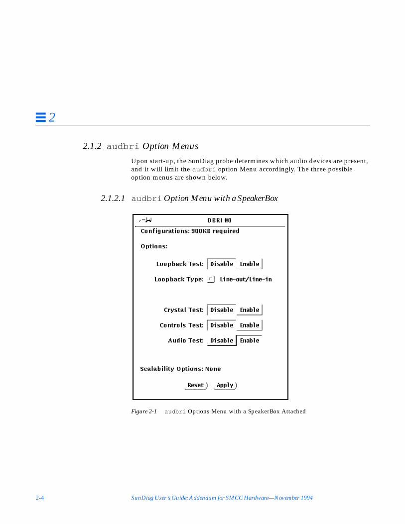
2.1.2 audbri Option Menus
Upon start-up, the SunDiag probe determines which audio devices are present,and it will limit the audbri option Menu accordingly. The three possibleoption menus are shown below.
2.1.2.1 audbri Option Menu with a SpeakerBox
Figure 2-1 audbri Options Menu with a SpeakerBox Attached

CPU Test Descriptions 2-5
2
2.1.2.2 audbri Option Menu for SPARCstation 5
Figure 2-2 audbri Option Menu for a SPARCstation 5

2-6 SunDiag User’s Guide: Addendum for SMCC Hardware—November 1994
2
2.1.2.3 audbri Option Menu for a SPARCstation LX without aSpeakerBox
Figure 2-3 audbri Option Menu for a SPARCstation LX
2.1.2.4 audbri Option Descriptions
Note – The Calibration and Reference File options can only be selected throughthe command line.
TypePress MENU to select the type of test to run. The choices are Line-in/Line-outand Line-in/Headphone.
LoopbackThis exclusive setting enables you to toggle the Loopback subtest on and off.
CalibrationUsed with the SpeakerBox to Microphone Loopback subtest. This exclusivesetting enables you to toggle the Calibration function on and off. Whenenabled, this function creates calibration files for the Loopback subtest to useas a baseline in future testing. The default reference file names are listed below.

CPU Test Descriptions 2-7
2
Crystal TestClick SELECT to enable or disable the Crystal subtest.
Controls TestClick SELECT to enable or disable the Controls subtest.
Audio TestClick SELECT to enable or disable the Audio test. This is the only subtestenabled by default.
Reference FileUsed with the SpeakerBox to Microphone Loopback subtest. If the SpeakerBoxto Microphone Loopback subtest and Calibration function are enabled, a newcalibration file will be created.
If the SpeakerBox to Microphone Loopback subtest is enabled and theCalibration function is disabled, the Loopback checks this text field for thecalibration file to test against. The default reference file created in/opt/SUNWdiag/bin is:
audbri_sbmic.data
2.1.3 audbri Command Line Syntax
/opt/SUNWdiag/bin/audbri B C D=/dev/sound/ <unit_no> F= reference_file_pathI=/dev/ ioctl_device M L S T= loopback_test_type X standard_arguments
Arguments
B Brief test. This is the same as specifying q for quick test.
C Loopback Calibration for SpeakerBox to Microphone
D=/dev/ audio_device Specifies the audio device to be tested. The default isD=/dev/sound/ <unit_no>
F=reference_file_path The default files created are:/opt/SUNWdiag/bin/audbri_sbmic.dataIf you use others, specify that path and filenames with thisoption. See T=loopback_test_type.
2-8 SunDiag User’s Guide: Addendum for SMCC Hardware—November 1994
2
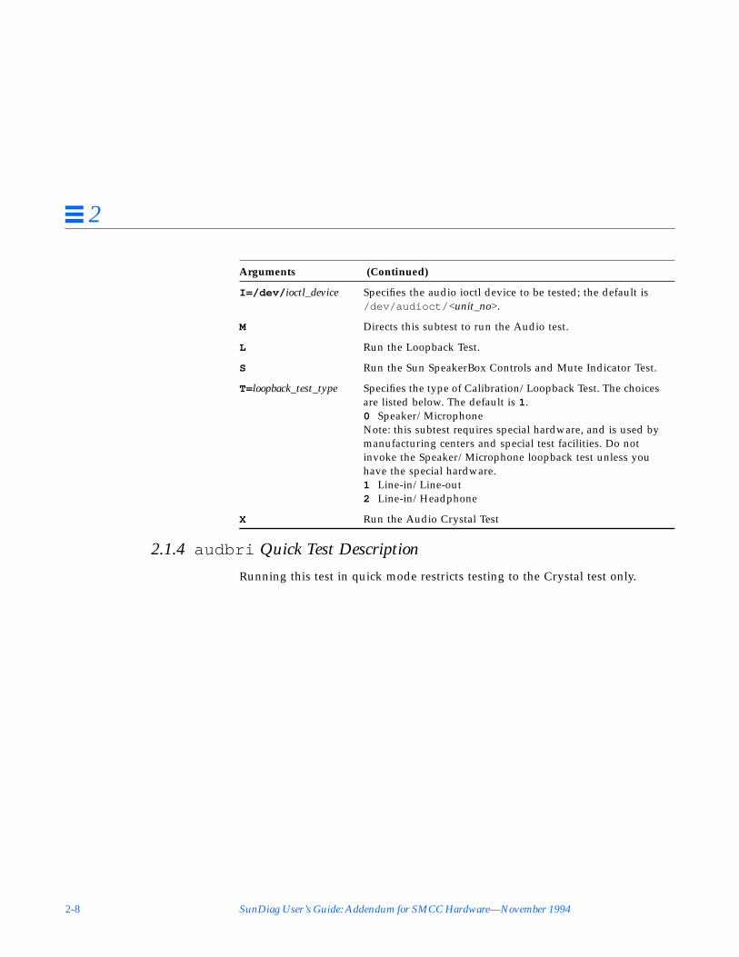
2.1.4 audbri Quick Test Description
Running this test in quick mode restricts testing to the Crystal test only.
I=/dev/ ioctl_device Specifies the audio ioctl device to be tested; the default is/dev/audioct/ <unit_no>.
M Directs this subtest to run the Audio test.
L Run the Loopback Test.
S Run the Sun SpeakerBox Controls and Mute Indicator Test.
T=loopback_test_type Specifies the type of Calibration/Loopback Test. The choicesare listed below. The default is 1.0 Speaker/MicrophoneNote: this subtest requires special hardware, and is used bymanufacturing centers and special test facilities. Do notinvoke the Speaker/Microphone loopback test unless youhave the special hardware.1 Line-in/Line-out2 Line-in/Headphone
X Run the Audio Crystal Test
Arguments (Continued)

CPU Test Descriptions 2-9
2
2.2 ISDN/DBRI Test (isdntest )This test verifies the functionality of the ISDN portion of the Dual Basic RateISDN (DBRI) chip.
2.2.1 isdntest Test Description
isdntest is actually a set of several subtests. Three main channels existwithin an ISDN: D, B1 and B2. In each of the following subtests, unlessotherwise indicated, the D channels will be in Basic Rate HDLC data mode, theB1 channels in 56 kbps HDLC data mode, and the B2 channels in 64 kbpsHDLC data mode. D channel packet size is 256 bytes, and B channel packetsize is 1024 bytes. The packet count will be 10 packets. Each channel runs as anindependent child process.
The first subtest is the local loopback test. It first checks the initial activationstate of the Network Termination (NT) and Terminal Equipment (TE) interfacesto make sure they are deactivated. It then activates each interface using the“force activation” capability of DBRI. Each interface is then put into localloopback mode (See Figure 2-4). Data residing in host memory is written toeach interface, which loops the data back onto itself. The data is then read backinto host memory and verified. Each channel, D, B1 and B2 is tested, with theexception of the TE D channel, which cannot be tested in local loopback mode.This test runs internal to the DBRI chip. This subtest does not require an NT toTE external loopback connector.
Figure 2-4 isdntest Local Loopback Subtest
HOST MEMORY
SBus
DBRITE NT
B2 B1 D D B1 B2

2-10 SunDiag User’s Guide: Addendum for SMCC Hardware—November 1994
2
The next subtest is the activation/deactivation test. This subtest runs throughthe activation/deactivation sequence for the NT and then the activationsequence for the TE. The T101 and T103 timers are set to 5 seconds. Thissubtest requires an NT to TE external loopback connector.
The remote loopback capability is tested next. The TE interface is put intoremote loopback mode, and the NT transmits data to the TE on all threechannels, D, B1 and B2 (See Figure 2-5). The TE loops all data back to the NTand reads a copy of it. Data is then verified. The whole process is then repeatedwith the TE transmitting to the NT, which is placed in remote loopback mode.This subtest requires an NT to TE external loopback connector.
Figure 2-5 isdntest Remote Loopback Subtest
Next, a read/write test is performed on all 6 of the ISDN channels: TE D, TEB1, TE B2, NT D, NT B1 and NT B2. The external loopback connector connectseach channel on the TE interface to its corresponding channel on the NT (SeeFigure 2-6). Six unique data patterns are used, one for each path. Packets readare compared against packets written. The test is repeated with the B1 channelsplaced in 64 kbps HDLC data mode and the B2 channels in 56 kbps HDLC datamode. This subtest requires an NT to TE external loopback connector.
DBRITE NT
B2 B1 D D B1 B2
SBus
External Loopback Connector
HOST MEMORY

CPU Test Descriptions 2-11
2
Figure 2-6 isdntest Read/Write Subtest
The next subtest is a packet size test. A read/write test, similar to the previousone, is performed with a packet count of 100. Each packet transmitted andreceived is a unique size, computed randomly. This subtest requires an NT toTE external loopback connector.
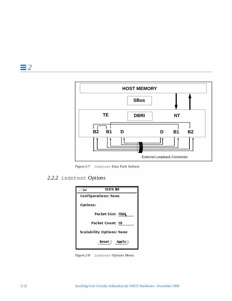
The last subtest is a data path test. Using the ISDN_SET_CHANNEL ioctl, datais routed through a series of short pipe interconnects within DBRI (SeeFigure 2-7). This subtest requires an NT to TE external loopback connector.
DBRITE NT
B2 B1 D D B1 B2
SBus
HOST MEMORY
External Loopback Connector
2-12 SunDiag User’s Guide: Addendum for SMCC Hardware—November 1994
2
Figure 2-7 isdntest Data Path Subtest
2.2.2 isdntest Options
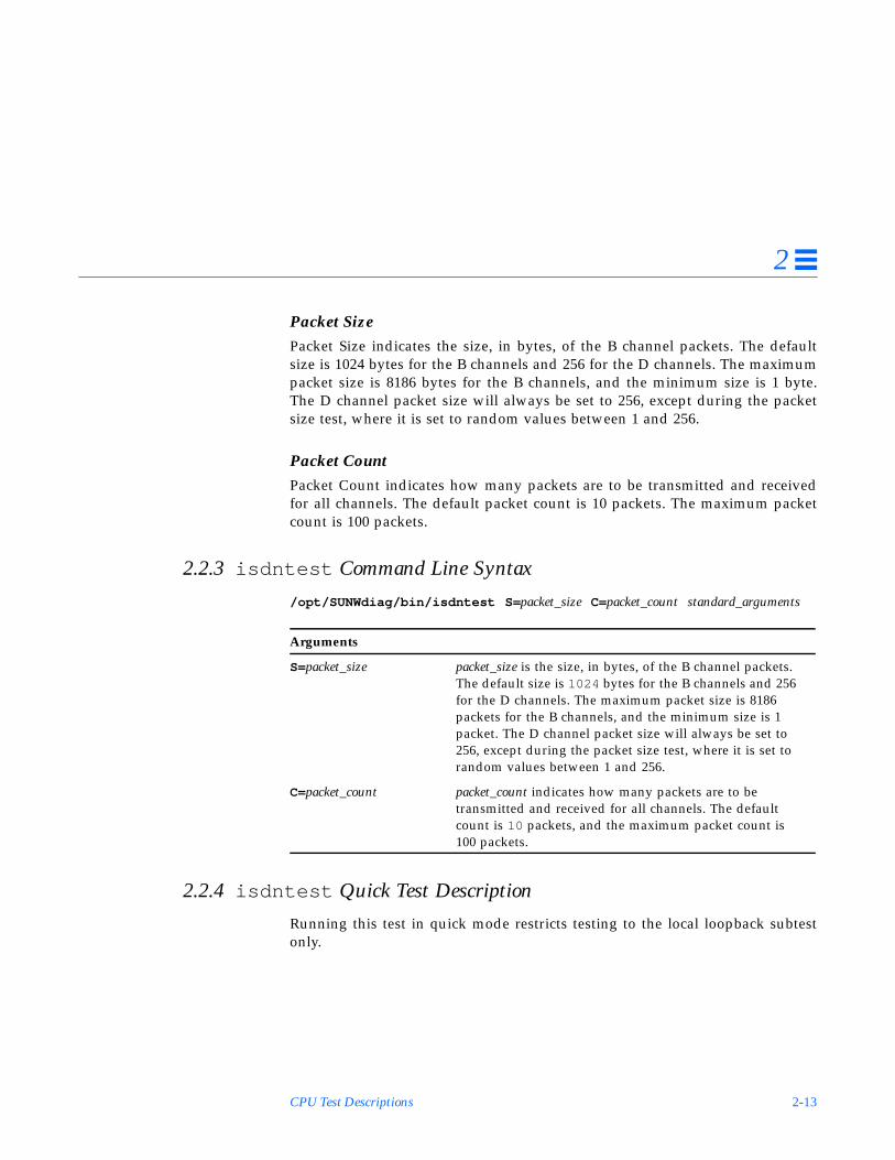
Figure 2-8 isdntest Options Menu
DBRITE NT
B2 B1 D D B1 B2
External Loopback Connector
SBus
HOST MEMORY
CPU Test Descriptions 2-13
2
Packet SizePacket Size indicates the size, in bytes, of the B channel packets. The defaultsize is 1024 bytes for the B channels and 256 for the D channels. The maximumpacket size is 8186 bytes for the B channels, and the minimum size is 1 byte.The D channel packet size will always be set to 256, except during the packetsize test, where it is set to random values between 1 and 256.
Packet CountPacket Count indicates how many packets are to be transmitted and receivedfor all channels. The default packet count is 10 packets. The maximum packetcount is 100 packets.
2.2.3 isdntest Command Line Syntax
/opt/SUNWdiag/bin/isdntest S= packet_size C= packet_count standard_arguments
2.2.4 isdntest Quick Test Description
Running this test in quick mode restricts testing to the local loopback subtestonly.
Arguments
S=packet_size packet_size is the size, in bytes, of the B channel packets.The default size is 1024 bytes for the B channels and 256for the D channels. The maximum packet size is 8186packets for the B channels, and the minimum size is 1packet. The D channel packet size will always be set to256, except during the packet size test, where it is set torandom values between 1 and 256.
C=packet_count packet_count indicates how many packets are to betransmitted and received for all channels. The defaultcount is 10 packets, and the maximum packet count is100 packets.

2-14 SunDiag User’s Guide: Addendum for SMCC Hardware—November 1994
2
2.2.5 isdntest Error Messages
Initial state on /dev/isdn/0/nt/mgt is ISDN_ACTIVATED
Using the NT management device driver on device 0, the initial activationstate on the NT interface is ISDN_ACTIVATED, which is incorrect.
Unable to activate with /dev/isdn/1/te/mgt.TE state = ISDN_DEACTIVATED NT state = ISDN_DEACTIVATED
Using the TE management device driver on device 1, the TE and NTinterfaces did not activate within the allowed period of time. The currentactivation state on both interfaces is ISDN_DEACTIVATED.
Data miscompare for NT B2 channel reader.Packet 6 offset 58 contains C8, should be A9.
The NT B2 channel was comparing packets read to those written and founda miscompare.

CPU Test Descriptions 2-15
2
2.3 Graphics Tower (gttest )SunDiag tests the Sun Graphics Tower with a sequence of subtests that canaccurately locate and identify failing FRUs (Filed Replaceable Units). All testsare nondestructive and maintain the system integrity during and after the testsare run.
Caution – Do not run any other application that uses the GT accelerator portwhile running gttest . This combination will cause SunDiag to returnincorrect errors.
Note – gttest requires approximately 1.5M bytes of disk space in the /tmpdirectory to extract its working files. If this space is not available, thediagnostic will fail and report warning and error messages indicating lack ofdisk space.
By default, SunDiag runs all of the available tests, except the Stereo test. Seethe Test Descriptions section below.
Note – To avoid excessive test cycle times when testing the GT GraphicsSubsystem, follow these instructions:
1. Enable Single Pass on the SunDiag Options menu.2. Enable Verbose on the SunDiag Options menu.3. Do not select any other diagnostic tests.
Following these procedures ensures that gttest will run once, report its statusas each test routine executes, and then exit.
Note – Disable all screen savers before testing any graphics device. Typexset s off at a UNIX prompt to disable the Solaris screen saver.
!

2-16 SunDiag User’s Guide: Addendum for SMCC Hardware—November 1994
2
Figure 2-9 gttest Options Menu

CPU Test Descriptions 2-17
2
2.3.1 gttest Test Description
The subtests are run in the order shown in Figure 2-10. The subtests assumethat the GT Graphics Subsystem has an active working interface with theSPARCstation CPU. If for any reason SunDiag cannot make the connection,further testing is not possible and SunDiag will report a fatal unrecoverableerror.
Figure 2-10 gttest Overview
SunDiag
Direct Port Test
Accelerator Port Test
Integration Test
Other tests (CPU, disk, etc.)
GT graphics subsystem tests
Video Memory and CLUTs tested from host
Front end local data memoryRendering pipeline setup processor shared memoryRendering pipelineVideo memory tested from front endFrame buffer output selection
Vector generationTriangle generationSpline curve generationViewport clippingHidden surface removalTransparencyDepth-cueingLighting and shadingText generationPickingArbitrationStereo (interactive)
2-18 SunDiag User’s Guide: Addendum for SMCC Hardware—November 1994
2
2.3.1.1 Direct Port Tests
The direct ports tests check the non-accelerated portion of the GT using thefollowing subtests.
Video Memory Array, Tested from HostThis subtest checks the frame buffer.
The video memory array subtest selects and tests 64 by 64 pixel regionscovering all video memory planes, including the 2 8-bit alpha/overlay planes,2 24-bit image planes, 24-bit depth (Z buffer) plane, 10-bit WID plane, and twocursor planes. If the subtest detects an error, SunDiag reports the defectiveplane and location.
CLUTsThis subtest checks the frame buffer.
This subtest performs a non-destructive read-write test on the frame buffercolor look up tables. If this subtest detects a failure, SunDiag reports thelocation of the failure.
At the beginning of this subtest, red, green, and blue stripes display for visualverification of the digital-to-analog converters (DACs).
2.3.1.2 Accelerator Port Tests
The accelerator port tests check the accelerated portion of the GT using thefollowing subtests.
Front End Local Data MemoryThis subtest checks the Graphics Processor Front End Board Local DataMemory.
The Local Data Memory subtest is a nondestructive read-write memory test.This subtest aborts at the first error and reports a memory failure.
Setup Processor Shared Memory TestThis subtest checks the graphics processor rendering pipeline.

CPU Test Descriptions 2-19
2
The Setup Processor shared memory subtest verifies that the i860microprocessor can write and read the setup processor shared memory withouterror.
Rendering PipelineThis subtest checks the graphics processor rendering pipeline.
The rendering pipeline subtest checks each of the three rendering pipelinestages: setup processor, edge walker, span interpolator, and Pixel BusMultiplexer. The Edge Walker and Span Interpolator subtests are a series ofsmall tests that verify the functionality of the edge walker and spaninterpolator ASICs in vectors, triangles, Gouraud shading, alpha blending, andanti-aliasing rendering. The results of the tests are verified by means ofchecksum values accumulated from data output by the Rendering Pipeline.SunDiag reports any subtest failures.
Video Memory Array, Tested from Front EndThis subtest checks the frame buffer.
This test makes sure that the video memory array can be accessed by the i860microprocessor via the Local Bus. This is a destructive read-write test whichverifies that all the Frame Buffer video memory locations are good. If thissubtest detects an error, SunDiag reports the defective plane and location.
Frame Buffer Output SectionThis subtest checks the frame buffer.
The Frame Buffer Output Section contains a diagnostic feedback register in theRAMDACs. The Frame Buffer Output Section subtest creates various windowsin the Window ID plane then sets up the look up tables (LUTs) associated withthese values. This subtest then writes known values to the video memory ofthese windows. Next, the frame buffer is switched into trace mode, whichreads the video through the diagnostic feedback register and puts the data intothe shadow memory. Finally, this subtest compares the contents of the shadowmemory with the expected values via checksum and determines if the OutputSection is operating properly.
If this subtest detects an error, the test reports the error, and the actual andexpected values are displayed on the system Console.

2-20 SunDiag User’s Guide: Addendum for SMCC Hardware—November 1994
2
2.3.1.3 Integration Test
The integration test is a sequence of subtests running GT display list programs.These subtests ensure the GT Graphics Subsystem integrity at the system level.The subtests test all features of the hardware at the application level, readingthe results from the frame buffer and verifying the results by comparingagainst known good images.
These tests use a frame buffer region of 1152 by 900 pixels, in the upper leftcorner of the screen, regardless of the size screen attached to the system. Thetests use previously-generated test images for each color plane (red, green, andblue). These test images are stored in a reduced size (1/64th the normal size) tosave disk space.
Vector GenerationThis subtest tests all Graphics Tower boards. The faulty component can bedetermined by analyzing the errors reported in the Direct Port and AcceleratorPort tests.
This subtest renders fairly large vector objects with aliased, anti-aliased, andshaded vectors.
Triangle GenerationThis subtest tests all Graphics Tower boards. The faulty component can bedetermined by analyzing the errors reported in the Direct Port and AcceleratorPort tests.
This subtest renders objects with aliased, anti-aliased shaded, and shadedtriangles.
Spline Curves GenerationThis subtest tests all Graphics Tower boards. The faulty component can bedetermined by analyzing the errors reported in the Direct Port and AcceleratorPort tests.
This subtest renders an object with both parametric and NURBS1 curves ofdifferent orders.
1. Non-Uniform Rational B-Splines.
CPU Test Descriptions 2-21
2
Viewport ClippingThis subtest tests all Graphics Tower boards. The faulty component can bedetermined by analyzing the errors reported in the Direct Port and AcceleratorPort tests.
This subtest renders and clips an object around and in front on the screen.
Hidden Surface RemovalThis subtest tests all Graphics Tower boards. The faulty component can bedetermined by analyzing the errors reported in the Direct Port and AcceleratorPort tests.
This subtest renders objects with the Z-buffer-compare attribute turned on.
Polygons Edges HighlightingThis subtest tests all Graphics Tower boards. The faulty component can bedetermined by analyzing the errors reported in the Direct Port and AcceleratorPort tests.
This subtest renders an object with the edge highlighting attribute turned on.
TransparencyThis subtest tests all Graphics Tower boards. The faulty component can bedetermined by analyzing the errors reported in the Direct Port and AcceleratorPort tests.
This subtest renders a scene with two transparency modes (standalone andalpha blend) in various degrees. This results in a two-pass transparency of theobjects in the scene.
Depth-CueingThis subtest tests all Graphics Tower boards. The faulty component can bedetermined by analyzing the errors reported in the Direct Port and AcceleratorPort tests.
This subtest renders an object with the depth-cueing attribute turned on.

2-22 SunDiag User’s Guide: Addendum for SMCC Hardware—November 1994
2
Lighting and ShadingThis subtest tests all Graphics Tower boards. The faulty component can bedetermined by analyzing the errors reported in the Direct Port and AcceleratorPort tests.
This subtest renders an object with multiple light sources and Gouraudshading for front and back surfaces.
Text GenerationThis subtest tests all Graphics Tower boards. The faulty component can bedetermined by analyzing the errors reported in the Direct Port and AcceleratorPort tests.
This subtest generates diverse text lines with different attributes for checking.
PickingThis subtest tests all Graphics Tower boards. The faulty component can bedetermined by analyzing the errors reported in the Direct Port and AcceleratorPort tests.
This subtest has two parts: a pick detect test and a pick echo test.
Animation and ArbitrationThis subtest checks the frame buffer.
This subtest renders a moving, double-buffered object into the image planewhile a second Solaris process performs a read-write test to the cursor andWID planes from the direct port on the Frame Buffer. This subtest simulatesconditions in the real world, where rendering processes and windowsoperations run concurrently.
Stereo (Interactive)This subtest checks the frame buffer.
This subtest displays an object in stereo mode. You must verify the properoperation by looking at the screen with stereo glasses. To terminate to the test,you must press q.
FB LockingSee the “Special Note on Testing Multiple Framebuffers” section in Chapter 1of the SunDiag User’s Guide for details.

CPU Test Descriptions 2-23
2
2.3.2 gttest Command Line Syntax
/opt/SUNWdiag/bin/gttest D= device_name S= subtest_number F= #_of_subtest_loopsB=#_of_test_loops L standard_arguments
Arguments
D=devicename devicename is the full path name of the device under test.The default is /dev/gt0 .
S=subtest_number subtest_number is the test number of the subtest to be run.Select from the subtests below. You can run multiplesubtests by adding the subtest numbers. For example,n=0x3 runs both test 1 and test 2; n=0x180 runs both test0x080 and test 0x0100. Note that you do not need theleading zeros. To run all tests, type n=0x7FFFF .0x 000 001 Direct port—video memories0x 000 002 Direct port—CLUTs and WID LUT0x 000 004 Accelerator port—front end Local Data
Memory0x 000 008 Accelerator port—setup processor shared
memory0x 000 010 Accelerator port—rendering pipeline0x 000 020 Accelerator port—video memories0x 000 040 Accelerator port—Frame buffer output
section0x 000 080 Integration test—vectors0x 000 100 Integration test—triangles0x 000 200 Integration test—spline curves0x 000 400 Integration test—viewport clipping.0x 000 800 Integration test—hidden surface removal0x 001 000 Integration test—polygon edges
highlighting0x 002 000 Integration test—transparency0x 004 000 Integration test—depth cueing0x 008 000 Integration test—lighting and shading0x 010 000 Integration test—text0x 020 000 Integration test—picking0x 040 000 Integration test—arbitration0x 080 000 Integration test—stereo (interactive)
F=#_of_subtest_loops #_of_subtest_loops is the number of loops for each subtest.The default is 1 (one loop)

2-24 SunDiag User’s Guide: Addendum for SMCC Hardware—November 1994
2
2.3.3 gttest Quick Test Description
Running this test in quick mode does not change the test procedure.
2.3.4 gttest Command Line Examples
Here are three examples of SunDiag gttest on-line commands. Make sure tochange directories to /opt/SUNWdiag/bin before running gttest from thecommand line. gttest is hard-wired to look for its data file, gttest.data , in/opt/SUNWdiag/bin .
1. A Simple accelerator port test, Frame Buffer output section, single pass:
2. All direct port tests, five loops of sequence:
3. All subtests (except the interactive tests), two loops of each subtest, fourloops of each test sequence:
B=#_of_test_loops #_of_test_loops is the number of loops of each test sequence.The default is 1 (one loop).
L Disables framebuffer locking. See the “Special Note onTesting Multiple Framebuffers” in Chapter 1 of the SunDiagUser’s Guide f or details.
# cd /opt/SUNWdiag/bin# gttest S=0x40
# cd /opt/SUNWdiag/bin# gttest S=0x3 B=0x5
# cd /opt/SUNWdiag/bin# gttest S=0x7FFFF F=2 B=4
Arguments (Continued)

CPU Test Descriptions 2-25
2
2.3.5 gttest Error Messages
The GT SunDiag error messages are described below. The error messages arelisted in alphabetical order.
Arbitration Test: Accelerator port drawing in doublebuffer mode, [plane group], [mode] Mode error at x=[x]y=[y], exp=[expected], obs=[observed], xor=[xor]. Suspectdaulty HFB.
Failed the Arbitration integration test. [plane group] is one of the following:Red Plane Group A, Overlay Plane Group A or B, Image Plane Group A orB, Cursor Plane Group, Cursor Enable Plane group, Z Buffer Plane Group,Hardware Window ID Plane Group, or Software Window ID Plane Group.[mode] is either byte or stencil access mode. The location of the anomaly aswell as the expected and observed values are also given. For pixel accessmode, the bank of the memory error is disclosed as well. “HFB” if the GTFrame Buffer board.
Arbitration Test: Accelerator port drawing in double buffermode, Direct port simultaneous write to both buffers, readfrom buffer [A or B] : [plane_group], Shapes error at[address]. Suspect faulty HFB.
Failed the Arbitration integration test. [plane_group] is one of the following:Image plane A or B, Depth plane, WID plane, Cursor plane, or Fast ClearPlane A or B. [address] is the linear address of the bad memory cell. “HFB”is the GT Frame Buffer Board.
Background process wouldn’t die. System error.
A software error. You may have to re-boot the SPARCstation.
Byte/Stencil Access Mode error at x=# y=#, exp=0x#,obs=0x#,xor=0x#. Suspect faulty HFB.
The direct port video memory test has found an error at pixel (x,y) in thecurrent plane group. Byte/Stencil Access Mode applies to all plane groupsthat access all 32 bits of the frame buffer memory (in other words, the eightbit image and overlay planes). The test expected to find exp but observedobs, yielding xor when the two values are exclusive or’d with each other.There may be a bad bit in the video memory.

2-26 SunDiag User’s Guide: Addendum for SMCC Hardware—November 1994
2
Cannot allocate enough memory for testing. Check swap spacesize and memory reserved for test.
Out of memory error. Increase swap space and/or kill other processes.
Cannot create screen raster for device [device]. Checkdevice for existence and/or permissions.
The device that you specified (the default is /dev/fbs/gt0 ) is not availableto the test. Make sure that you are executing the test on a machine with aGT, and that you have permission to access it.
Can’t open display list file [filename]. Suspect incompleteor incorrect hardware installation. Files may also havebeen corrupted because file system ran out of space in/tmp.
Indicates a software initialization problem. [filename] is the file thatSunDiag can’t open. Also, approximately 1.5 Mbytes of free space isrequired in /tmp.
Can’t open [filename] to dump frame buffer.
The test needed to open a file to dump the contents of the frame buffer. Usedf to check drive space, and also to check file permissions.
Can’t read display list file [filename]. Suspect incompleteor incorrect hardware installation. Files may also havebeen corrupted.
Indicates a software initialization problem. [filename] is the display list filethat SunDiag can’t read.
CLUT #n, index #, color [color], expected 0x#, received0x#.
An error was found in one the fifteen color look up tables tested bySunDiag. The error was found in the nth CLUT. The index is out of 256entries in each CLUT. Each CLUT has eight bits each for red, green, andblue. The color indicates in which set of eight bits the error was found. Byusing the expected and received values, you can figure out which bit isincorrect.

CPU Test Descriptions 2-27
2
Communication with Graphics Engine failed. Suspectincomplete or incorrect software installation. Front-EndFirmware may also be dead.
SunDiag is unable to communicate with the GT Graphics Subsystem. Asoftware error or hardware error with the GT SBus Adapter Board, HACCable, or Front End Board.
Cursor plane error: Failed with error code [code]:[failure]. Suspect faulty HFB.
Failed accelerator port video memory test. [code] is the error code number.[failure] is an explanation of the error indicated by [code]. “HFB” is the GTFrame Buffer Board.
Depth cueing: Error(s) found in [RED], [GREEN], [BLUE}components.
Failed the depth cueing integration test. Only the failing component (RED,GREEN, or BLUE) appears in the message.
Depth plane error: Failed with error code [code]:[failure]. Suspect faulty HFB.
Failed accelerator port video memory test. [code] is the error code number.[failure] is an explanation of the error indicated by [code]. “HFB” is the GTFront End Board.
Display list file is too big for the remaining VM!hdl_size=0x#, vm_size=0x#
Increase swap space or close other running processes.
Failed to allocate unique WID for 24-bit plane. Suspectincomplete or incorrect software installation.
A problem with system initialization.
Failed to get monitor mode: [ERROR] Software error.
A software error. May have to re-boot the SPARCstation.
Failed to set diagnostic mode. Software error.
A software error. May have to re-boot the SPARCstation.

2-28 SunDiag User’s Guide: Addendum for SMCC Hardware—November 1994
2
Failed to set monitor mode. Software error.
A software error. May have to re-boot the SPARCstation.
Fast Clear Plane [A or B] error: Failed with error code[code]: [failure]. Suspect faulty HFB.
Failed accelerator port video memory test. [code] is the error code number.[failure] is an explanation of the error indicated by [code]. “HFB” is the GTFront End Board.
At FE firmware program counter 0x#, expected display listinstruction 0x#, observed 0x#.
You may have a bad Front End processor board.
Front End (Firmware) not responding. This may indicate thatthe Firmware has died. Try to run gtconfig.
A hardware problem. SunDiag was unable to communicate with the FrontEnd Board. Indicates a problem with the SBus Adapter Board, HAC cable,or Front End Board.
Got XCPU interrupt, but user_mcb_ptr->trap_instruction =0x#, expect 0x#. System software error.
A software error. May have to re-boot the SPARCstation.
Got XCPU interrupt, but it’s not a trap instruction, errorcode = # : [message]. This may indicate that the Firmwarehas died. Try to run gtconfig.
A software error. [message] further describes the problem. May have to re-boot the SPARCstation.
Hidden Surface Removal: *** Error(s) found in [RED],[GREEN], [BLUE} components.
Failed the hidden surface removal integration test. Only the failingcomponent (RED, GREEN, or BLUE) appears in the message.
hk_disconnect failed. System software error.
A software error. May have to re-boot the SPARCstation.

CPU Test Descriptions 2-29
2
hk_munmap failed. System software error.
A software error. May have to re-boot the SPARCstation.
hk_open failed. GT system is either not initialized or notconnected.
A software error. May have to re-boot the SPARCstation.
Image plane [A or B] error: Failed with error code [code]:[failure]. Suspect faulty HGPFE.
Failed accelerator port video memory test. [code] is the error code number.[failure] is an explanation of the error indicated by [code]. “HGPFE” is theGT Front End Board.
LDM error: Failed with error code [code]: [failure].Suspect faulty HGPFE.
Failed the accelerator port test of the Front End Local Data Memory. [code]is the error code number. [failure] is an explanation of the error indicated by[code]. “HGPFE” is the GT Frame End Board.
Lighting and Shading: *** Error(s) found in [RED], [GREEN],[BLUE] components.
Failed the lighting and shading integration test. Only the failing component(RED, GREEN, or BLUE) appears in the message.
Pick Detect misses:%d lines and/or triangles inside thepickbox and/or %d lines and triangles outside the pickbox.
Failed the Picking integration test. Only the failing component (RED,GREEN, or BLUE) appears in the message.
Pick Echo failed: *** Error(s) found in [RED], [GREEN],[BLUE} components.
Failed the Picking integration test. Only the failing component (RED,GREEN, or BLUE) appears in the message.
Picking: *** Error(s) found in [RED], [GREEN], [BLUE}components.
Failed the picking integration test. Only the failing component (RED,GREEN, or BLUE) appears in the message.

2-30 SunDiag User’s Guide: Addendum for SMCC Hardware—November 1994
2
Pixel Access Mode error at x=# y=#, bank=#,exp=0x#,obs=0x#, xor=0x#. Suspect faulty HFB.
The direct port video memory test has found an error at pixel (x,y) in thecurrent plane group. Pixel Access Mode applies to all plane groups that donot access the frame buffer memory four bytes at a time. (In other words, allplanes except eight bit planes). The memory for the pixel resides in thegiven memory bank. The test expected to find exp but observed obs ,yielding xor when the two values are exclusive or’d with each other. Theremay be a bad bit in the video memory.
Poly Edges Highlighting: *** Error(s) found in [RED],[GREEN], [BLUE} components.
Failed the poly edges highlighting integration test. Only the failingcomponent (RED, GREEN, or BLUE) appears in the message.
Rendering Pipeline error: Failed with error code [code]:[failure]. Suspect faulty HGPRP.
Failed the accelerator port Rendering Pipeline test. [code] is the error codenumber. [failure] is an explanation of the error indicated by [code].“HGPRP” is the GT Front End Board.
Spline Curves: *** Error(s) found in [RED], [GREEN], [BLUE}components.
Failed the spline curves integration test. Only the failing component (RED,GREEN, or BLUE) appears in the message.
SU Shared RAM error: Failed with error code [code]:[failure]. Suspect faulty HGPRP.
Failed the accelerator port Rendering Pipeline Setup Processor shared RAMtest. [code] is the error code number. [failure] is an explanation of the errorindicated by [code]. “HGPRP” is the GT Front End Board.
System initialization failed. Suspect incomplete orincorrect software installation. Front-End Firmware mayalso be dead.
System initialization failed. Most likely a hardware problem with the GTFront End Board.

CPU Test Descriptions 2-31
2
‘tar’ never finished. System software problem.
Make sure that the tar program is installed correctly on your system. Also,use df to see if you have enough disk space left in your /tmp directory.
tar: [error]
Make sure that the tar program is installed correctly on your system. Also,use df to see if you have enough disk space left in your /tmp directory.
Texts: Error(s) found in [RED], [GREEN], [BLUE} components.
Failed the texts integration test. Only the failing component (RED, GREEN,or BLUE) appears in the message.
This program requires the default setting of 5 HW and 5 SWWID Planes. Run gtconfig.
Each of the GT’s ten WID planes can be allocated as a hardware or softwareWID plane. Some programs may change the allocation from the default (5hardware, 5 software) and forget to change it back. Run gtconfig to set theallocation back to the default.
This program requires the default setting of 5 HW and 5 SWWID Planes. Enter “unsetenv XNEWS_WID_PLANES” and tryagain.
Each of the GT’s ten WID planes can be allocated as a hardware or softwareWID plane. Programs that use the Shapes libraries that need to change theallocation from the default (5 hardware WID planes and 5 software WIDplanes) do so by setting the environment variable XNEWS_WID_PLANES tothe desired number of hard WID planes. A program has set thisenvironment variable, and you must unset it in order to run the GT SunDiagtests.
Transparency: *** Error(s) found in [RED], [GREEN], [BLUE}components.
Failed the transparency integration test. Only the failing component (RED,GREEN, or BLUE) appears in the message.

2-32 SunDiag User’s Guide: Addendum for SMCC Hardware—November 1994
2
Triangles: *** Error(s) found in [RED], [GREEN], [BLUE}components.
Failed the triangles integration test. Only the failing component (RED,GREEN, or BLUE) appears in the message.
Unable to open /dev/fbs/gt0. Check device for existenceand/or permission.
SunDiag is unable to open the GT device driver. Make sure that there is a/dev/fbs/gt0 device driver and that the permissions are correct.
Vectors: *** Error(s) found in [RED], [GREEN], [BLUE}components.
Failed the vectors integration test. Only the failing component (RED,GREEN, or BLUE) appears in the message.
vfork: [error]
An error has occurred while trying to fork a child process. Increase swapspace, or close other running processes.
Viewport Clipping: *** Error(s) found in [RED], [GREEN],[BLUE} components.
Failed the viewport clipping integration test. Only the failing component(RED, GREEN, or BLUE) appears in the message.
WID plane error: Failed with error code [code]: [failure].Suspect faulty HFB.
Failed accelerator port video memory test. [code] is the error code number.[failure] is an explanation of the error indicated by [code]. “HFB” is the GTFront End Board.

CPU Test Descriptions 2-33
2
2.4 cgsix Frame Buffer, GX and GX+ Options Test (cg6test )cg6test verifies the cgsix frame buffer and the GX options offered with mostSPARC™ based workstations and servers.
Note – Disable all screen savers before testing any graphics device. Typexset s off at a UNIX prompt to disable the Solaris screen saver.
2.4.1 cg6test Test Description.
This test stresses the frame buffer with the subtests described below.
Cursor TestThis is a visual test of the overlay registers of the RAMDAC. A pointer isdrawn on the screen and moved around to predetermined locations. There is aproblem if the pointer disappears. This visual test ensures that the overlay isworking properly.
Fast Copy in Double Buffer Test ModeTwo full-size screen rasters images are created in double buffer mode. Differentpatterns are written to each of them. The hidden buffer is copied to the visiblebuffer, and the data is compared. An error message is returned if there areinconsistencies. Then the buffer is flipped and the process is repeated.
Note – This test only applies to Sun Microsystems GX+ graphic acceleratorswith double-buffering capacity.
TEC TestThe TEC verifies that the Transformation Engine and Cursor control logic arebeing accessed. This confirms that further TEC access will be performedcorrectly.
FBC TestThe FBC test verifies that the Frame Buffer Controller logic is being accessed.This confirms that further FBC access will be performed correctly.
2-34 SunDiag User’s Guide: Addendum for SMCC Hardware—November 1994
2
Frame Buffer TestThis test verifies that the frame buffer memory is working. A walking 1’spattern is written to memory, with a specific color signifying one of eight bits.The screen is divided into eight equally wide vertical stripes. A walking one iswritten to each stripe, causing eight iterations of these stripes. The valuewritten is read back and checked. If the values do not match, an error isreported.
Screen Test Using BlitsThis test draws blocks of color and performs blit transfers to other portions ofthe screen. First, the entire screen is drawn with cyan color, then a black blockis put in the upper left corner. This subtest blits this block on the upper right,lower right, and lower left corners, then or’s the whole image.
Blit TestA block of data is drawn, and blit into a location at the bottom right rectangle.
Line TestLines with different data values are drawn on the screen and appear indifferent colors. The data is read back and compared with the expected values.An error is returned in the case of a mismatch.
Polygon TestHourglass-shaped polygons are drawn on the screen, using the four vertices.After all the polygons are rendered in the video memory, they are read backand the data compared with expected values. If there is a mismatch, an error isdisplayed.
Colormap TestAll 256 locations in the color map are loaded with a greyscale both backwardsand forwards manner. This means decreasing values are loaded to all R, G, andB values.
Warning – If the system under test has a monochrome or greyscale monitor,visual color problems are undetectable.

CPU Test Descriptions 2-35
2
Figure 2-11 cg6test Options Menu
2.4.2 cg6test Options
FB LockingSee the “Special Note on Testing Multiple Framebuffers” section in Chapter 1of the SunDiag User’s Guide for details.
2.4.3 cg6test Command Line Syntax
/opt/SUNWdiag/bin/cg6test L standard_arguments
Note – Extra Swap Space Required: 5 MB
2.4.4 cg6test Quick Test Description
Running this test in quick mode does not change the test procedure.
Arguments
L Disables framebuffer locking. See the “Special Note on TestingMultiple Framebuffers” in Chapter 1 of the SunDiag User’s Guidefor details.

2-36 SunDiag User’s Guide: Addendum for SMCC Hardware—November 1994
2
2.4.5 cg6test Error Messages
cg6test returns the error messages described below for subtest failures:
CG6 <subtest> failure, x pos = < failure location>, y pos = < failurelocation>, exp = < expected value>, actual = < actual value>
The named subtest could not complete successfully.
CG6plus VRAM(s) to probe: U#
The polygon test prints these messages for a TurboGX framebuffer.
Colormap error - red, loc =< failure location>, exp = < expectedvalue>, actual = < actual value>
Colormap error - green, loc =< failure location>, exp = < expectedvalue>, actual = < actual value>Colormap error - blue, loc =< failure location>, exp = < expected
value>, actual = < actual value>
Couldn’t create new screen for < device>.
SunDiag could not open up a memory area for simulating frame buffermemory, where: <device> = /dev/fb, /dev/cgsix0, or/dev/cgsix n
Could not create child raster
The color map test and frame buffer tried to create a child raster. If there isnot enough memory available, this test may fail.
Error in opening device /dev/cgsix
The device could not be opened. A wrong device name was supplied.Rebooting with the -r option is required if new devices are installed inSolaris 2.x systems. See “New Device Drivers” on page 1-2 of this book.
Error: ERROR_MALLOC_FAILED
Not enough memory was available during color map and frame buffermemory testing.

CPU Test Descriptions 2-37
2
Failed to create raster
The raster to do a graphics operation could not be opened. There might notbe enough memory available, or the wrong raster name was supplied.
Failed to get cmap
Not enough memory was available.
Failed to create context
Not enough memory was available.
render_main: can’t map lego
cg6test was not able to map the framebuffer board register addresses.
render_main: TEC_EXCEPTIONbuild_view_matrix: TEC_EXCEPTION
The TEC section of the frame buffer logic had an exception during thenamed routine.
clear_window: DRAWSTATUS
A DRAWSTATUS error occurred during the clear_window routine.
2-38 SunDiag User’s Guide: Addendum for SMCC Hardware—November 1994
2
2.5 cgtwelve Frame Buffer, GS Test (cg12 )The GS is an integrated frame buffer and 3D graphics accelerator for desktopSPARCstations.
Note – The user interface is locked out while this test is being run. You canstop this test with the Stop button on the SunDiag window, or temporarily haltthe test by pressing Control-C.
Note – Disable all screen savers before testing any graphics device. Typexset s off at a UNIX prompt to disable the Solaris screen saver.
2.5.1 cg12 Test Description
The cg12 test operates on two levels, the host level and the C30 level.
Note – The GS accelerator includes a Texas Instruments TMS320C30 DSP chip.Throughout this manual, it is referred to as the C30.
The Host LevelThe host level includes test code based on the SunView window system, theGPSI libraries, and a specially-compiled version of the Pixrect™ libraries. Thisis the main part of the cg12 test. The test results are verified by reading out theimage memory with the Pixrect library, reducing the resolution, and thenverifying with the supplied test images. The test images are generated on acontrol system for each of the color planes (red, blue, and green).
There are two reasons for reducing the size of the test images.
• Large test images occupy too much disk space on the root directory of thesystem.
• The test images may not match the result of the tests pixel by pixel evenwhen the hardware is functioning perfectly. This is due to the roundingerror of different floating point hardware and the eventual displacementsproduced by different Firmware revisions (C30 GPSI).

CPU Test Descriptions 2-39
2
The test results are first reduced 64 times by averaging all 8x8 pixel blocks to asingle value and then comparing them with the test images. Each comparedpixel is allowed to be within a certain tolerance range to compensate for thevariations mentioned above. The tolerance range is small enough to sensefunctional abnormalities and yet big enough to accommodate expectedvariations. In case of error, the respective 8x8 pixel block turns black and itslocation is reported.
C30 LevelThe C30 level with test code is linked to the GPSI code. The host posts anunpublished GPSI SunDiag command with a number of parameters (10). TheGPSI command interpreter calls a SunDiag subroutine that examines theparameters passed to it and determines which test to call. The test result ispassed back to the host through one of the parameters. The host hangs andwaits until it receives the completion flag from the test. If the C30 test codedies, the host will time out after a couple of seconds.
Figure 2-12 shows the tests implemented in the cg12 test. You can select thesubtests to be run and the loop counts for each subtest and each board. Thedefault selection for all subtests and loop counts is one.

2-40 SunDiag User’s Guide: Addendum for SMCC Hardware—November 1994
2
Figure 2-12 cg12 Options Menu

CPU Test Descriptions 2-41
2
2.5.2 cg12 Options
DSPCovers all the internal C30 registers (int and float ), on-chip RAM, andinteger and floating point instruction executions (parallel instructions). TheRAM test is a nondestructive read/write test with the patterns 0x5a5a5a5a and0xa5a5a5a5. During the RAM test, all interrupts are disabled. The registers aretested with the patterns 0x55555555 and 0xaaaaaaaa.
SRAM & DRAMThe SRAM test switches on each page of the 4 SRAM pages and executes theDSP test on the selected SRAM page. The DRAM test is the same RAM test runagain on the DRAM space, except that it excludes the space where the test coderesides. (The test code resides in DRAM.)
Video MemoriesSelects and tests all 64x64 Pixrect regions covering the entire video memoryplanes (including overlay, zbuffer, window ID). The image planes are testedboth single and double buffered. All regions are tested with random patternsgenerated each time the test is called.
Look up TablesThe look up tables in the RAMDAC are tested with a read/write test and arandom table. The random table is generated each time the test is called.
Vectors GenerationThis test has three parts. First it generates concentric circles with flat shadedvectors in red, green, blue, yellow, and white. If the result is successfullyverified (described above), then an object with color shaded vectors isrendered. If the result of this test is also correct, then an object (hexnut) isgenerated with wide textured lines. The result of each part is then verified asabove with test images previously stored.
Polygons GenerationFlat shaded polygons are rendered, and the result is verified with previouslystored test images.

2-42 SunDiag User’s Guide: Addendum for SMCC Hardware—November 1994
2
TransformationsAn object (the spaceship Enterprise) is rendered and transformed in 3D severaltimes to give the impression of moving in space. It leaves a path when it movesaway. The path has to match the expected path in the test images previouslystored.
Clipping & HiddenThis test has three parts: clipping, hidden surface removal, and picking. In theclipping test, two objects are generated and the view port is clipped so thatonly parts of them are visible. In the hidden surface removal test, objects(“pacmen”) are generated and should overlay each other correctly in the orderof the Z component. In the picking test, a pick window is set and triangles andpolygons are generated inside and outside. The results of the clipping andhidden surface removal test are verified with test images previously stored. Inthe picking test, the pick events are counted.
Depth CueingAn object is rendered with the Depth Cue Attribute turned on. The result isverified with test images previously stored.
Lighting & ShadingA cylinder composed with polygons and triangles is rendered with multiplelight sources and Gouraud shading mode. The zbuffer is on. The result isverified with test images previously stored.
ArbitrationTwo Solaris processes are running simultaneously. One process renders flatshaded polygons and vectors at random locations on screens into the 24-bitimage plane, while the other accesses the overlay plane, the overlay enableplane, and the window ID plane. If the second process has problems with readand write to and from any of the mentioned planes, the test reports the error.Otherwise the test passes. A visual image with three color stripes (RGB) isshown at the end for visual verification of the RAMDAC.
FB LockingSee the “Special Note on Testing Multiple Framebuffers” section in Chapter 1of the SunDiag User’s Guide for details.

CPU Test Descriptions 2-43
2
2.5.3 cg12 Command Line Syntax
/opt/SUNWdiag/bin/cg12 D= device_name s= subtest_number F= #_of_loopsB=#_of_loops L standard_arguments
Note – Extra Swap Space Required: 3 MBytes
Arguments
D=device_name The full path name of the device must be specified.
s=subtest_number subtest_number specifies the number (a binary representation) ofthe subtest choices to be run. The default is -1 (all subtests run).More than one subtest choice can be selected by ordering theirsubtest numbers.Example: n = 3 specifies that the DSP and SRAM & DRAMsubtests are run. The following subtest choices can be specified:
-1 All subtests
1 DSP
2 SRAM and DRAM
4 Video Memories
8 Look Up Tables
16 Vectors Generation
32 Polygons generation
64 Transformations
128 Clipping and Hidden
256 Depth Cueing
512 Lighting and Shading
1024 Arbitration
F=#_of_loops Number of loops for each subtest
B=#_of_loops Number of loops for each board
L Disables framebuffer locking. See the “Special Note on TestingMultiple Framebuffers” in Chapter 1 of the SunDiag User’s Guidefor details.

2-44 SunDiag User’s Guide: Addendum for SMCC Hardware—November 1994
2
Note – Make sure to change directories to /opt/SUNWdiag/bin beforerunning cg12 from the command line. cg12 is hard-wired to look for its datafiles, cg12.data and cg12.data.gsxr , in /opt/SUNWdiag/bin .
2.5.4 cg12 Quick Test Description
Running this test in quick mode restricts testing to the DSP subtest (subtestflag set to 1).
2.5.5 cg12 Error Messages
The following errors described below are reported in case of hardware failures:
Registers Test failed
One or more DSP registers failed. The DSP chip is flawed.
On-chip Memory Test failed
DSP chip problem; the on-chip memory failed the memory test.
Integer Instructions Test failed
DSP chip problem; integer instructions were not performed correctly.
Float Instruction Test failed
DSP chip problem; float instructions were not performed correctly.
DRAM error
The DRAM does not pass the memory test. An unbundled softwarediagnostics package, the SunDiagnostic Executive, can help you locate thefailure.
SRAM error in page (0-3)
SRAM page (0-3) does not pass the memory test. An unbundled softwarediagnostics package, the SunDiagnostic Executive, can help you locate thefailure.

CPU Test Descriptions 2-45
2
<Plane>: Pixrect error at < address>
The Video Memory indicated failed the memory test.< Plane> can bewindow ID, 8-bit compatibility, 24-bit color, or Overlay and Overlay Enable.
error at index < index>, write < pattern>, read < pattern>
The hardware look-up table is defective at the location index. The writtenand expected patterns are shown against the actual pattern.
Error(s) found in (RED, GREEN, BLUE) component(s)
The generated patterns do not match the expected patterns in theirindicated components.
The vectors generation, polygon generation, transformations, clipping andhidden, depth cueing, and lighting & shading tests have the same errormessage:
<type> pick test: detected < num> misses < position> of the pickwindow out of total < total> picking events
The Picking test has generated an interrupt error. <type> = triangle orpolygon , <num> = number of pick events missed, <position> = in , out oron , and <total> = number of pick events generated.
Pixrect error in < Plane> at < address>
The access in the indicated plane has error(s) at the indicated address whenthe drawing engine is drawing graphics at the same time. Possibly a localbus error.
Note – The above error messages are for hardware only. Any other errormessages reported are software error messages and will indicate any necessaryaction.

2-46 SunDiag User’s Guide: Addendum for SMCC Hardware—November 1994
2
2.6 Color Graphics Frame Buffer Test (cg14test )This test checks the cg14 frame buffer card. cg14test is specific to the VSIMM(Video SIMM)/SX Memory Controller devices in the SPARCstation 10 SX.
WarningsBecause of possible conflicts between SunDiag cg14 framebuffer tests andOpenWindows applications that use the cg14 framebuffer, the followingrestrictions apply when running the cg14test SunDiag test:
• Do not run any graphic applications other than OpenWindows while theSunDiag software is running framebuffer tests
• Do not run any OpenWindows programs that generate video updatesoutside or on top of the SunDiag window
• Do not close the SunDiag window to an icon while it is running framebuffertests
• Make sure to enable the framebuffer locking option from the Optionswindow (see “FB Locking” on page 2-54)
2.6.1 cg14test Test Description
cg14test has 9 distinct test groups:
1. MDI and VBC Chip Control Registers
2. Memory Chips
3. MDI Chip Cursor Registers
4. MDI Chip Clut registers
5. DAC Chip Registers
6. MDI Chip XLU Registers
7. CG14 Display (visual only)
8. MDI Chip Testmode Readback in 8-bit mode
9. Driver IOCTRLs

CPU Test Descriptions 2-47
2
Hardware Test Groups (test groups 1 - 6)Testing is done by opening /dev/fbs/cgfourteenX , mmap’ing (R/WShared) the MDI Control Address Space, modifying the target test location(using direct writes to the mmap’ed address space), reading from the mmap’edaddress space for verification, and closing the device.
Visual Pattern Test Group (test group 7)Testing is done by loading a visual pattern of 256 colors, then rotating thepattern around by adjusting CLUT1. This subtest must be verified visually.
Data Propagation Test Group (test group 8)Testing is done by loading the frame buffer (FB) memory with four neutraldata patterns, then setting a target FB pixel with data that will trigger thetestmode readback latch. The result is read from the readback register aftervertical blanking occurs. Two different trigger patterns used at each FB pixel.All four MDI pixel paths (A - D) are used, and the pixel locations for eachtrigger are designed to detect gross MDI input data opens or short, VRAMSAM addressing, and VRAM -> SAM transfer addressing.
The screen will show four horizontal bars, which will be either greyscale ofcolored. These bars will change each time the trigger data is inverted, and as itcompletes the testing of a raster pattern.
Note – This test will test in 8 bits per pixelmode. If the resolution and VRAMsize allows, 32 bits per pixelmode will also be tested automatically.
Driver Test Group (test group 9)Test all IOCTL calls that have not yet been used to verify proper drivercommunication to the hardware. Call the driver to perform a hardware update,and then confirm that update was successful by using the complementarydriver read, or reading the mmap’ed address space and comparing it againstthe stimulus.
Notes1. cg14test performs appropriate steps, from this list, before and after each
test (if possible), to maintain context and prevent visual confusion:

2-48 SunDiag User’s Guide: Addendum for SMCC Hardware—November 1994
2
a. Save register data before overwriting it.
b. Disable video if possible.
c. Do the specific test.
d. Restore the saved register data info.
2. The data used for register testing will be optimized to include all 0’s, all 1’s,and walking a 1 through each bit under test.
2.6.1.1 MDI and VBC Chip Control Registers (test group 1)
Master Control Register bits 7-0 w/r verify.Packed Pixel Register bits 3-0 w/r verify.Master Status Register bits 7-4 r/o verify 0x00 and 0x30 occur.Horizontal Blank Start Register bits 9-0 w/r verify.Horizontal Blank Clear Register bits 9-0 w/r verify.Horizontal Sync Set Register bits 9-0 w/r verify.Horizontal Sync Clear Register bits 9-0 w/r verify.Composite Sync Clear Register bits 9-0 w/r verify.Vertical Blank Start Register bits 11-0 w/r verify.Vertical Blank Clear Register bits 11-0 w/r verify.Vertical Sync Set Register bits 11-0 w/r verify.Vertical Sync Clear Register bits 11-0 w/r verify.Transfer Cycle Set Register bits 9-0 w/r verify (MDI revision 0 only).Transfer Cycle Clear Register bits 9-0 w/r verify (MDI revision 0 only).Fault Status Address Register bits 15-0 w/r verify.Auto-increment Address Space Register bits 7-0 w/r verify.Video Base Register bits 23-12 w/r verify.
2.6.1.2 Memory Chips (test group 2)
VRAM TestingThe Data Bus Test will use 18 NTA patterns (Nair, Thatte, and Abraham’stesting procedure for RAM) to check for data and address faults. This test willbe performed in MDI_CHUNKY_XBGR_MAP access mode only.
The test operates as follows.
• Ascend through the FB memory clearing it to 0s

CPU Test Descriptions 2-49
2
• NTA pattern test number x reads a location to make sure test data y is there,and then writes new data z to that location. The location ascends throughthe FB sequentially.
Memory RetentionVRAM Data Retention checks for gross problems with the VRAM refresh. Sincerefresh is active during this test, no retention problems should occur unless therefresh is defective.
Table 2-1 cg14test NTA Testing Patterns
NTA Test Pattern Number = x Test Data = y New Data = z
1.0 0x00000000 0x01010101
1.5 0x01010101 0xffffffff
2.1 0xffffffff 0xf1f1f1f1
2.2 0xf1f1f1f1 0x33333333
3.1 0x33333333 0xf0f0f0f0
3.2 0xf0f0f0f0 0x0f0f0f0f
4.1 0x0f0f0f0f 0x55555555
4.2 0x55555555 0xaaaaaaaa
5.1 0xaaaaaaaa 0x05050505 (1x)0x88888888 (2x)
5.2 0x88888888 0xf5f5f5f5
6.1 0xf5f5f5f5 0x00000000 (1x)0x5f5f5f5f (2x)
6.2 0x5f5f5f5f 0x11111111
7.1 0x11111111 0x00000000 (1x)0xcccccccc (2x)
7.2 0xcccccccc 0xdbdbdbdb
8.1 0xdbdbdbdb 0x6d6d6d6d
8.2 0x6d6d6d6d 0x6b6b6b6b
9.1 0x6b6b6b6b 0x0000000
9.2 0x00000000 -
2-50 SunDiag User’s Guide: Addendum for SMCC Hardware—November 1994
2
This test turns off the video, writes 0’s to all the VRAM, waits the specifiedmemory_hold time (the default is 5 Seconds), then reads/compares all VRAMdata. This process is repeated with data of f’s, then the video is restored andthe test is complete.
There are two new command line parameters related to this test, R=number andH=number. R= allows the user to specify the refresh interval from 128-1023. Thisis the time between refresh cycles and the system default is 123. H= allows theuser to specify the retention test hold time in seconds.
Test Write RecoveryA write recovery test will be used in all the EMC mapping modes to write datato 0’s followed by immediately reading that data location to see if the VRAMcan recover from a write correctly. This is done to all sequential ascendinglocations. Next, a second independent pass of memory is made with thecomplementary data of 0xffffffff being written to descending locations of theFB memory buffer.
The EMC mapping access modes are:
a. MDI_CHUNKY_XGBR_MAP
b. MDI_CHUNKY_BGR_MAP
c. MDI_PLANAR_X16_MAP
d. MDI_PLANAR_C16_MAP
e. MDI_PLANAR_X32_MAP
f. MDI_PLANAR_B32_MAP
g. MDI_PLANAR_G32_MAP
h. MDI_PLANAR_R32_MAP
2.6.1.3 MDI Chip Cursor Registers (test group 3)
Cursor Plane 0 Register bits 31-0 w/r verify.Cursor Plane 1 Register bits 31-0 w/r verify.Cursor Plane 0 Register bits 31-0 w/r verify. (w/auto increment)Cursor Plane 1 Register bits 31-0 w/r verify. (w/auto increment)Cursor Control Register bits 2-0 w/r verify.Cursor Color Register 1 bits 28-0 w/r verify.Cursor Color Register 2 bits 28-0 w/r verify.X-Cursor Location Register bits 11-0 w/r verify.

CPU Test Descriptions 2-51
2
Y-Cursor Location Register bits 11-0 w/r verify.Cursor Plane 0 Non-Auto Registers testCursor Plane 0 Auto Registers testCursor Plane 1 Non-Auto Registers testCursor Plane 1 Auto Registers testCursor Planes Retry A testCursor Planes Retry B test
2.6.1.4 MDI Chip Clut Registers (test group 4)
LUT1 Registers 0-255 bits 31-27 & 23-0 w/r verify.LUT1 Registers 0-255 bits 31-27 & 23-0 w/r verify. (w/auto increment)LUT1D Registers 0-255 bits 31-27 & 23-0 w/r verify.LUT1D Registers 0-255 bits 31-27 & 23-0 w/r verify.(w/auto increment)LUT2 Registers 0-255 bits 31-27 & 23-0 w/r verify.LUT2 Registers 0-255 bits 31-27 & 23-0 w/r verify. (w/auto increment)LUT2D Registers 0-255 bits 31-27 & 23-0 w/r verify.LUT2D Registers 0-255 bits 31-27 & 23-0 w/r verify.(w/auto increment)LUT3 Registers 0-255 bits 31-27 & 23-0 w/r verify.LUT3 Registers 0-255 bits 31-27 & 23-0 w/r verify. (w/auto increment)LUT3D Registers 0-255 bits 31-27 & 23-0 w/r verify.LUT3D Registers 0-255 bits 31-27 & 23-0 w/r verify.(w/auto increment)
2.6.1.5 DAC Chip Registers (test group 5)
RAMDAC RegistersAddress Register bits 7-0 (0x7 maximum) w/r verify.Mode Register bits 7-0 (skip bit 5) bits w/r verify.
Control RegistersID Register bits 7-0 r/o verify data is 0x8C.Pixel-Mask Register bits 7-0 w/r verify. (skipped if dac rev = 2)Command2 Register bits 7-0 w/r verify. (skipped if dac rev = 2)Command3 Register bits 7-0 w/r verify. (skipped if dac rev = 2)

2-52 SunDiag User’s Guide: Addendum for SMCC Hardware—November 1994
2
2.6.1.6 MDI Chip Xlut Registers (test group 6)
XLUT Registers 0-255 bits 7-0 w/r verify.XLUT Registers 0-255 bits 7-0 w/r verify. (w/auto increment)XLUTD Registers 0-255 bits 7-0 w/r verify.XLUTD Registers 0-255 bits 7-0 w/r verify. (w/auto increment)
2.6.1.7 CG14 Display (visual only) (test group 7)
This visual displays 256 boxes on the screen (each in a different color), andthen shifts the CLUT1 entries giving the visual impression of the patternmirroring itself from left to right horizontally. The pattern then rotates up,down, followed by mirroring itself horizontally left to right.
2.6.1.8 MDI Chip Testmode Readback [TMRB] (test group 8)
Note – This test always runs in 8 bit mode, but it will also run in 32 bit modeif the Framebuffer size and resolution permit.
Test Mode Readback Register bits 23-0 r/o verify.
2.6.1.9 Driver IOCTRLs (test group 9)• MDI_GET_CFGINFO check # of cluts, pixel height, pixel width, and pixel
mode against h/w.• FBIOGATTR check real_type, fb_height, fb_width, fb_depth, fb_cmsize, and
fb_size against cfginfo values.• FBIOGTYPE check fb_type, fb_height, fb_width, fb_depth,fb_size, and
fb_cmsize against driver defines or cfginfo values.• FBIOGVIDEO check status returned against h/w.• FBIOSVIDEO set off, off, on, on, off verifying against h/w.• FBIOVERTICAL (imbedded in FBIOSVIDEO use!)• MDI_VRT_CNTL turn off, off, on, on, off the video interrupt enable and
verify the h/w agrees.• MDI_SET_PIXELMODE set different modes and verify against the h/w.• MDI_SET_PPR set the different modes and verify against the h/w.• MDI_SET_COUNTERS set HSS, HSC, XCC, HBC, XCS, HBS, CSC, VSS,
VSC, VBC, VBS, HCT, and VCT then verify against h/w.• MDI_GET_GAMMALUT check driver gammalut info against ramdac.

CPU Test Descriptions 2-53
2
• MDI_SET_GAMMALUT write to driver then check against ramdac.• MDI_SET_DEGAMMALUT set driver degammalut, then read the driver
info and compare it to what was set.• MDI_GET_DEGAMMALUT checked in conjunction with
SET_DEGAMMALUT.• MDI_GAMMA_CORRECT turn off, off, on, on, off the driver gamma
correction and check against the diaginfo status.• MDI_SET_XLUT set xlut and verify against h/w.• MDI_GET_XLUT get xlut and verify against h/w.• MDI_SET_CLUT set clut (1-3 as applicable) and verify against h/w.• MDI_GET_CLUT get clut (1-3 as applicable) and verify against h/w.• FBIOPUTCMAP set and verify clut1 matches.• FBIOGETCMAP verify clut1 matches get.• FBIOSATTR set emu_type to FBTYPE_MDICOLOR and verify with• FBIOGATTR check.• FBIOGCURMAX verify x and y size match driver defines.• FBIOSCURSOR verify set at 3 locations matches h/w.• FBIOGCURSOR verify driver knows what set(s) just did.• FBIOSCURPOS verify set at 3 locations matches h/w.• FBIOGCURPOS verify driver knows what set(s) just did.• MDI_SET_CURSOR set then check CCR, XCU, and YCU cursor h/w
registers.
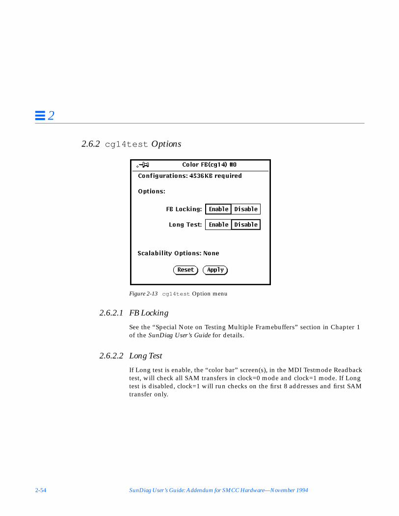
2-54 SunDiag User’s Guide: Addendum for SMCC Hardware—November 1994
2
2.6.2 cg14test Options
Figure 2-13 cg14test Option menu
2.6.2.1 FB Locking
See the “Special Note on Testing Multiple Framebuffers” section in Chapter 1of the SunDiag User’s Guide for details.
2.6.2.2 Long Test
If Long test is enable, the “color bar” screen(s), in the MDI Testmode Readbacktest, will check all SAM transfers in clock=0 mode and clock=1 mode. If Longtest is disabled, clock=1 will run checks on the first 8 addresses and first SAMtransfer only.

CPU Test Descriptions 2-55
2
2.6.3 cg14test Command Line Syntax
/opt/SUNWdiag/bin/cg14test D= device L X Passes= x I R= x H=x T
standard_arguments
2.6.4 cg14test Quick Test Description
If the q (quick test) option from the standard arguments is specified, cg14testruns 1 minute faster, since the MDI readback test is skipped. All of the othertest are run when q is invoked.
2.6.5 cg14test Error Messages
Error messages in cg14test specify the failing test name, including the chipand suspected faulty function. If DEBUG and VERBOSE modes are off, the endof the message contains a prioritized list of user-replaceable FRUs (FieldReplaceable Units).
Arguments
D=device Specify the path of the cg14 device file to be tested.For example: D=/dev/fbs/ device_name
L Disables window system locking option. See the “Special Noteon Testing Multiple Framebuffers” in Chapter 1 of the SunDiagUser’s Guide for details. Do not use when device is the windowsystem display.
X Extra long TMRB test. Specify to run longer version of MDIreadback.Note: The q option overrides this option.
Passes= x x is the number of passes to run. The default is 1 pass.
I Enable optional driver ioctl tests for cursor.Note: Do not the move mouse during the cg14test when thisoption is run.
R=x Specify the time between refresh cycles (128-1023).The default is 123.
H=x Specify the retention test hold time in seconds.
T Logic analyzer trigger on TMRB/memory errors.

2-56 SunDiag User’s Guide: Addendum for SMCC Hardware—November 1994
2
Note that the Visual checker pattern shifting test may not generate any errormessages, and must be verified visually.
The following information is appended to the end of any error messages:
followed by a sorted list containing any of the following FRUs for the specificfailure:
• Operator error• CG14 video board• CPU board• Video cable• Video monitor• CG14 device file• SunOS™• SunDiag• Unsupported feature
2.6.5.1 Error Message List
Note – In all error messages below, n is a hexadecimal number.
MDI Chip Messages
MDI Master Control Register exp=0xnn obs=nnMDI Packed Pixel Register exp=0xnn obs=nnMDI H-Blank Start Register exp=0xnnnn obs=nnnnMDI H-Blank Clear Register exp=0xnnnn obs=nnnnMDI H-Sync Set Register exp=0xnnnn obs=nnnnMDI H-Sync Clear Register exp=0xnnnn obs=nnnnMDI C-Sync Clear Register exp=0xnnnn obs=nnnnMDI V-Blank Start Register exp=0xnnnn obs=nnnnMDI V-Blank Clear Register exp=0xnnnn obs=nnnnMDI V-Blank Set Register exp=0xnnnn obs=nnnnMDI V-Blank Clear Register exp=0xnnnn obs=nnnnMDI Xfer-Cycle Set Register exp=0xnnnn obs=nnnnMDI Xfer-Cycle Clear Register exp=0xnnnn obs=nnnn
; *** suspected FRU(s)

CPU Test Descriptions 2-57
2
MDI Fault Status Address Register exp=0xnnnn obs=nnnnMDI Cursor Plane 0 Register 0xnn exp=0xnnnnnnnnobs=nnnnnnnnMDI Cursor Plane 1 Register 0xnn exp=0xnnnnnnnnobs=nnnnnnnnMDI X-Control Location Register exp=0xnnnn obs=nnnnMDI Y-Control Location Register exp=0xnnnn obs=nnnnMDI Control Color Register 1 exp=0xnnnnnnnn obs=nnnnnnnnMDI Control Color Register 2 exp=0xnnnnnnnn obs=nnnnnnnnMDI Cursor Control Register exp=0xnn obs=nnMDI Cursor Plane 0 Non-Auto Register 0xnn exp=0xnnnnnnnnobs=nnnnnnnnMDI Cursor Plane 0 Auto Register 0xnn exp=0xnnnnnnnnobs=nnnnnnnnMDI Cursor Plane 1 Non-Auto Register 0xnn exp=0xnnnnnnnnobs=nnnnnnnnMDI Cursor Plane 1 Auto Register 0xnn exp=0xnnnnnnnnobs=nnnnnnnnMDI Cursor Planes Retry test maximum retry limit exceededMDI Clut1 Register 0xnn exp=0xnnnnnnnn obs=nnnnnnnnMDI Clut1 Auto Register 0xnn exp=0xnnnnnnnn obs=nnnnnnnnMDI Clut1 Diag Register 0xnn exp=0xnnnnnnnn obs=nnnnnnnnMDI Clut1 Diag Auto Register 0xnn exp=0xnnnnnnnnobs=nnnnnnnnMDI Clut2 Register 0xnn exp=0xnnnnnnnn obs=nnnnnnnnMDI Clut2 Auto Register 0xnn exp=0xnnnnnnnn obs=nnnnnnnnMDI Clut2 Diag Register 0xnn exp=0xnnnnnnnn obs=nnnnnnnnMDI Clut2 Diag Auto Register 0xnn exp=0xnnnnnnnnobs=nnnnnnnnMDI Clut3 Register 0xnn exp=0xnnnnnnnn obs=nnnnnnnnMDI Clut3 Auto Register 0xnn exp=0xnnnnnnnn obs=nnnnnnnnMDI Clut3 Diag Register 0xnn exp=0xnnnnnnnn obs=nnnnnnnnMDI Clut3 Diag Auto Register 0xnn exp=0xnnnnnnnnobs=nnnnnnnnMDI Xlut Register 0xnn exp=0xnn obs=nnMDI Xlut Auto Register 0xnn exp=0xnn obs=nnMDI Xlut Diag Register 0xnn exp=0xnn obs=nnMDI Xlut Diag Auto Register 0xnn exp=0xnn obs=nn

2-58 SunDiag User’s Guide: Addendum for SMCC Hardware—November 1994
2
PCG Chip Message
MDI Pixel Clock Frequency %d is not supported
where %d is an integer indicating the unsupported clock frequency.
VBC Chip Messages
VBC Video Base Register exp=0xnnnnnnnn obs=nnnnnnnnVBC Control Register exp=0xnnnnnnnn obs=nnnnnnnnVBC VCR Register, RRI value, exp=0xnnnnnnnn obs=nnnnnnnn
RAMDAC Chip Messages
DAC Address Register exp=0xnn obs=nnDAC Mode Register exp=0xnn obs=nnDAC Control ID Register exp=0xnn obs=nnDAC Control Dac-Test Register exp=0xnnn obs=nnnDAC Control Sync-Test Register exp=0xn obs=nDAC Control Pixel-Mask Register exp=0xnn obs=nnDAC Control Command2 Register exp=0xnn obs=nnDAC Control Command3 Register exp=0xnn obs=nnDAC CMAP Register red[0xnn] exp=0xnnn obs=nnnDAC CMAP Register green[0xnn] exp=0xnnn obs=nnnDAC CMAP Register blue[0xnn] exp=0xnnn obs=nnn
VRAM Chip Messages
MEM (%s), NTA %s offset= 0xnnnnnnnn exp=0xnnnnnnnnobs=nnnnnnnnMEM (%s), WRRD %s offset= 0xnnnnnnnn exp=0xnnnnnnnnobs=nnnnnnnnMEM (%s), Data Retention offset=0xnnnnnnnn exp=0xnnnnnnnnobs=nnnnnnnn
where first %s can be one of the following:
CHUNKY_XBGR_MAPPEDCHUNKY_BGR_MAPPEDPLANAR_X16_MAPPEDPLANAR_C16_MAPPEDPLANAR_X32_MAPPED

CPU Test Descriptions 2-59
2
PLANAR_B32_MAPPEDPLANAR_G32_MAPPEDPLANAR_R32_MAPPED
and second %s will be a pattern number for NTA (see Table 2-1) and indicatethe direction (incremental or decremental) of writes for WRRD.

2-60 SunDiag User’s Guide: Addendum for SMCC Hardware—November 1994
2
CG14 Driver IOCTL Messages
IOCTL( %r) %s
where:
Table 2-2 cg14test Driver IOCTL Error Messages (1 of 3)
%r = %s =
MDI_CFGINFO
MDI_DIAGINFO “call failed, errno=%u” ;“number of cluts, exp 0x%x obs 0x%x” ;“pixel height, exp 0x%x obs 0x%x” ;“pixel width, exp 0x%x obs 0x%x” ;“unknown pixel mode, obs 0x%x” ;“pixel mode, exp 0x%x obs 0x%x
MDI_SET_PIXELMODE “unable to set %d-bit mode” ;
MDI_SET_PPR “ppr, exp 0x%x obs 0x%x” ;
MDI_SET_COUNTERS “hss, exp 0x%x obs 0x%x” ;“hsc, exp 0x%x obs 0x%x” ;“hbc, exp 0x%x obs 0x%x” ;“hbs, exp 0x%x obs 0x%x” ;“vss, exp 0x%x obs 0x%x” ;“vsc, exp 0x%x obs 0x%x” ;“vbc, exp 0x%x obs 0x%x” ;“vbs, exp 0x%x obs 0x%x” ;“csc, exp 0x%x obs 0x%x” ;“xcs, exp 0x%x obs 0x%x” ;“xcc, exp 0x%x obs 0x%x” ;
MDI_SET_GAMMALUT “red” ;“green” ;“blue” ;
MDI_GET_GAMMALUT
MDI_GAMMA_CORRECTION “gamma correction, exp 0x%x obs 0x%x” ;
MDI_SET_CLUT “clut, offset 0x%x exp 0x%x obs 0x%x” ;
MDI_GET_CLUT
MDI_SET_XLUT

CPU Test Descriptions 2-61
2
MDI_GET_XLUT “driver xbuf, offset 0x%x exp 0x%x obs 0x%x” ;“xlut, offset 0x%x exp 0x%x obs 0x%x” ;
FBIOGATTR “type, exp 0x%x obs 0x%x” ;“height, exp 0x%x obs 0x%x” ;“width, exp 0x%x obs 0x%x” ;“cmap size, exp 0x%x obs 0x%x” ;“fb size, exp 0x%x obs 0x%x” ;“depth, exp 0x%x obs 0x%x” ;“real_type, exp 0x%x obs 0x%x” ;
FBIOGTYPE
FBIOPUTCMAP
FBIOGETCMAP “red, offset 0x%x exp 0x%x obs 0x%x” ;“green, offset 0x%x exp 0x%x obs 0x%x” ;“blue, offset 0x%x exp 0x%x obs 0x%x” ;
FBIOSCURSOR
FBIOGCURSOR “set, exp 0x%x obs 0x%x” ;“enable, exp 0x%x obs 0x%x” ;“x hot position, exp 0x%x obs 0x%x” ;“y hot position, exp 0x%x obs 0x%x” ;“cmap index, exp 0x%x obs 0x%x” ;“cmap count, exp 0x%x obs 0x%x” ;“cmap red pointer, exp 0x%x obs 0x%x” ;“cmap green pointer, exp 0x%x obs 0x%x” ;“cmap blue pointer, exp 0x%x obs 0x%x” ;“cursor x size, exp 0x%x obs 0x%x” ;“cursor y size, exp 0x%x obs 0x%x” ;“image pointer, exp 0x%x obs 0x%x” ;“mask pointer, exp 0x%x obs 0x%x” ;
FBIOSCURPOS
FBIOGCURPOS
FBIOGCURMAX “x position, exp 0x%x obs 0x%x” ;“y position, exp 0x%x obs 0x%x” ;
FBIOVERTICAL
FBIOSVIDEO
Table 2-2 cg14test Driver IOCTL Error Messages (2 of 3)
%r = %s =
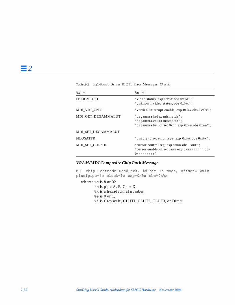
2-62 SunDiag User’s Guide: Addendum for SMCC Hardware—November 1994
2
VRAM/MDI Composite Chip Path Message
MDI chip TestMode ReadBack, %d-bit %s mode, offset= 0x%xpixelpipe=%c clock=%e exp=0x%x obs=0x%x
where: %d is 8 or 32%c is pipe A, B, C, or D,%x is a hexadecimal number.%e is 0 or 1,%s is Greyscale, CLUT1, CLUT2, CLUT3, or Direct
FBIOGVIDEO “video status, exp 0x%x obs 0x%x” ;“unknown video status, obs 0x%x” ;
MDI_VRT_CNTL “vertical interrupt enable, exp 0x%x obs 0x%x” ;
MDI_GET_DEGAMMALUT “degamma index mismatch” ;“degamma count mismatch” ;“degamma lut, offset 0xnn exp 0xnn obs 0xnn” ;
MDI_SET_DEGAMMALUT
FBIOSATTR “unable to set emu_type, exp 0x%x obs 0x%x” ;
MDI_SET_CURSOR “cursor control reg, exp 0xnn obs 0xnn” ;“cursor enable, offset 0xnn exp 0xnnnnnnnn obs0xnnnnnnnn”
Table 2-2 cg14test Driver IOCTL Error Messages (3 of 3)
%r = %s =

CPU Test Descriptions 2-63
2
2.7 Pixel Processor Test (sxtest )This test checks models of SPARCstation 10 machines equipped with an on-board Pixel Processor module. sxtest is specific to the VSIMM (VideoSIMM)/SX Memory Controller) devices in the SPARCstation 10 SX.
WarningsBecause of possible conflicts between cg14 SunDiag framebuffer tests andOpenWindows applications that use the cg14 framebuffer, the followingrestrictions apply when running the sxtest SunDiag test:
• Do not run any graphic applications other than OpenWindows while theSunDiag software is running framebuffer tests
• Do not run any OpenWindows programs that generate video updatesoutside or on top of the SunDiag window
• Do not close the SunDiag window to an icon while it is running framebuffertests
• Make sure to enable the framebuffer locking option from the Optionswindow for the system console cg14 device (see “FB Locking” on page 2-64)
• If sxtest is run with its VRAM enabled, then framebuffer locking must alsobe enabled
2.7.1 sxtest Description
This test locates load error, store error, ALU error, logic error etc. of the PixelProcessor by reading and verifying data from the control registers of the PixelProcessor, virtual memories, or video memories. This test also verifies theintegration function of the CG14 frame buffer and its device driver, videomemories, and data memories. sxtest also writes a test pattern to the framebuffer for visual verification.
sxtest is a series of 16 modules, described below.

2-64 SunDiag User’s Guide: Addendum for SMCC Hardware—November 1994
2
2.7.2 sxtest Options
Figure 2-14 sxtest Option Menu
FB LockingSee the “Special Note on Testing Multiple Framebuffers” section in Chapter 1of the SunDiag User’s Guide for details. Frame buffer locking is enabled bydefault on the window server running the OpenWindows software.
CMEM (Contiguous Memory)Choose either Enable or Disable. You must choose Disable if your system hasless then 4 MBytes of contiguous memory available.

CPU Test Descriptions 2-65
2
VRAM (Video Random Access Memory)Choose either to Enable or Disable the video random access memory.
Warning – If sxtest is run with its VRAM enabled, then framebuffer lockingmust be enabled or the SunDiag software will result in errors.
2.7.3 sxtest Module Descriptions
2.7.3.1 Display (Module0)
Click enable to display visual patterns.
3 subtests call the SPAM library and display pictures to verify the integrity of asubset of the kernel and the SPAM libraries via the SPARCstation 10 SX videosystem. These routines are ported from the SPAM demonstration programs. Allsubtests in this module are skipped if the cg14 frame buffer does not exist, or ifthe VRAM is disabled.
• rect_test — The screen is filled with random rectangles. The rectanglesare drawn in CHUNKY_XBGR mode if 32-bit mode OpenWindows isrunning. If not, they are drawn in CHUNKY_C8 mode with the SPAMlibrary routine sl_rect_fill_32 .
• shaa — A picture of shaded lines is drawn in CHUNKY_BGR mode withthe SPAM library routines sl_line_shaa_32 , sl_span_load_8 andsl_rect_fill_8 .
Note – The shaa test will be skipped if test is running on an 8 bit window.
• lines — The screen is filled with lines of various colors. These lines aredrawn in CHUNKY_XBGR mode if 32-bit mode OpenWindows is running;If not, they are drawn in CHUNKY_C8 mode with SPAM library routinesl_line_fill_8 .
2.7.3.2 SMCALL (Module1)
Click enable for a brief test of all sxtest functionalities.

2-66 SunDiag User’s Guide: Addendum for SMCC Hardware—November 1994
2
11 subtests are called from spam.smcall to verify the general function of theSMC chip. All subtests have a cg14 version and a non-cg14 version. Thesesubtests will repeat four times, each time with the IQ FIFO programmed to adifferent number of entries (8, 16, 32, and 64).
• shift_ldst• instr_mix *• arith_ldst• cmp_ldst• select_ldst• interlock_all *• logic_ldst• mult_ldst• rop• scat_ldst• delt_ldst
* These subtests are skipped if the VRAM option is set to disable.
2.7.3.3 SMC (Module2)
Click enable to test sx instructions with VRAM page crossing.
17 subtests are called from spam.smc . The smc_pagex1 sub-tests verifyspam_ldla instructions when effect addresses are crossing memory page. Thesmc_rampx sub-tests verify Ram Page Crossing Error logic with spam_ldlainstructions. Both DRAM address space and all VRAM Mode address spacesare covered. All subtests have a cg14 version and a non-cg14 version.
Because 8 Mbyte VRAMs and 4 Mbyte VRAMs are assembled with differentRAM chips, you must set the VRAM option correctly.
• smc_pagex1_0 *• smc_pagex1_1• smc_pagex1_2• smc_pagex1_3• smc_pagex1_4• smc_pagex1_5• smc_pagex1_6• smc_pagex1_7

CPU Test Descriptions 2-67
2
• smc_pagex1_8
• sp_pagex8_1 *• sp_pagex9_1 *
* These subtests are skipped if the CMEM option is set to disable.
• smc_rampx_1_8k• smc_rampx_2_8k• smc_rampx_3_8k• smc_rampx_4_8k• smc_rampx_5_8k• smc_rampx_6_8k• smc_rampx_7_8k• smc_rampx_8_8k• smc_rampx_1_16k• smc_rampx_2_16k• smc_rampx_3_16k• smc_rampx_4_16k• smc_rampx_5_16k• smc_rampx_6_16k• smc_rampx_7_16k• smc_rampx_8_16k
These subtests are only tested when there are
These subtests are only tested when there are
4 Mbytes of VRAM on the cg14 board.
8 Mbytes of VRAM on the cg14 board.

2-68 SunDiag User’s Guide: Addendum for SMCC Hardware—November 1994
2
2.7.3.4 REGF (Module3)
Click enable to test the register file pointer logic.
22 subtests are called from spam.regfile to verify the register file’s logicwith assorted SPAM instructions.
• readpointer1 *• readpointer2 *• readpointer3 *• readpointer4 *• writepointer1 *• writepointer2 *• writepointer3 *• writepointer4 *• readpointer5 *• writepointer5 *• rdptr0 †• wrptr0 †• rdptr1 †• wrptr1 †• rdptr2 †• wrptr2 †• rdptr3 †• wrptr3 †• rdptr4 †• wrptr4 †• rdptr5 †• wrptr5 †
* These subtests are skipped if the VRAM option is disabled.
† These subtests are skipped if the CMEM option is disabled.
CPU Test Descriptions 2-69
2
2.7.3.5 Megacell (Module4)
Click enable to test basic ASIC cell elements.
8 subtests verify the megacell functionalities of SMC chip. Megacell is the basiccell for SMC chip. These subtests are converted with test vectors from LSI. Allsubtests have a cg14 version and a non-cg14 version.
• 16bitadder — tests 16-bit adder in comp block.• alu_adder1 — tests 32-bit adder in comp block.• alu_adder2 — does delta operations.• alu_comparator1 — tests 32bit comparator in ADGEN.• alu_shifter1 — tests shifter in alu block.• m16 — tests 16 bit multiplier.• registerfile_RR32X32M — tests registerfile.• registerfile_RR8X3207M — tests write buffer. This subtest is skipped if
VRAM option is set to disable.
2.7.3.6 MUL (Module5)
Click enable to test the multiplier operations.
8 subtests are called, and each subtest has 2500 randomly generated MULSPAM macros. Each subtest tests SPAM MUL instruction sets by executingrandom SPAM MUL macro patterns. For example:
spam_dot(S_0,R42,R45,R31,5)spam_mulr(L_16,R44,R29,R52,1)spam_mul(S_15,R115,R114,R58,4)spam_mul(L_16,R89,R110,R81,8)spam_mulr(S_8,R21,R76,R53,1)spam_saxpr(S_8,R54,R46,R98,2)spam_dotr(L_16,R75,R40,R20,5)spam_dot(L_16,R44,R45,R84,4)spam_saxp(L_0,R93,R96,R44,8)spam_mulr(L_0,R86,R56,R56,5)spam_dotr(L_0,R14,R62,R40,2spam_saxpr(S_15,R112,R85,R95,7)

2-70 SunDiag User’s Guide: Addendum for SMCC Hardware—November 1994
2
• sp_mul0• sp_mul1• sp_mul2• sp_mul3• sp_mul4• sp_mul5• sp_mul6• sp_mul7
2.7.3.7 ALU (Module6)
Click enable to test ALU operations.
5 subtests are called, and each subtest has 2500 randomly generated ALUSPAM macros. Each subtest tests SPAM ALU instruction sets by executingrandom SPAM ALU macro patterns. For example:
spam_subv(R101,R31,R42,1)spam_subs(R90,R44,R90,14)spam_subv(R44,R70,R29,14)spam_sum(R58,R95,R114,9)spam_adds(R54,R46,R98,10)spam_addi(R9,51,R68,9)spam_abs(R76,R28,7)spam_addv(R80,R59,R93,11)
• sp_alu0• sp_alu1• sp_alu2• sp_alu3• sp_alu4
2.7.3.8 ROP (Module7)
Click enable to test the ROP operations.
5 subtests are called, and each subtest has 2500 randomly generated ROPSPAM macros. Each subtest tests SPAM ROP instruction sets by executingrandom SPAM ROP macro patterns. For example:

CPU Test Descriptions 2-71
2
spam_selb(R101,R31,R42,1)spam_ropl(R90,R27,R44,14)spam_sels(R19,R16,R112,15)spam_ropm(R47,R29,R96,16)spam_selb(R52,R43,R29,5)spam_ropb(R115,R114,R58,7)spam_selv(R57,R75,R16,2)spam_ropm(R110,R93,R83,13)
• sp_rop0• sp_rop1• sp_rop2• sp_rop3• sp_rop4
2.7.3.9 LOGIC (Module8)
Click enable to test the logical operations.
5 subtests are called, and each subtest has 2500 randomly generated LOGICSPAM macros. Each subtest tests SPAM LOGIC instruction sets by executingrandom SPAM LOGIC macro patterns. For example:
spam_xors(R101,R31,R42,1)spam_xori(R90,101,R90,14)spam_xorv(R30,R19,R95,13)spam_ands(R108,R16,R125,1)spam_andv(R115,R114,R58,7)spam_ors(R46,R89,R8,16)spam_orv(R57,R75,R16,2)spam_andi(R9,51,R68,9)
• sp_logic0• sp_logic1• sp_logic2• sp_logic3• sp_logic4

2-72 SunDiag User’s Guide: Addendum for SMCC Hardware—November 1994
2
2.7.3.10 SHIFT (Module9)
Click enable to test the shift operations.
5 subtests are called, and each subtest has 2500 randomly generated SHIFTSPAM macros. Each subtest tests SPAM SHIFT instruction sets by executingrandom SPAM SHIFT macro patterns. For example:
spam_sllv(R101,R31,R42,1)spam_slli(R90,5,R90,14)spam_srai(R30,19,R95,13)spam_srli(R108,16,R125,1)spam_sllv(R52,R43,R29,5)spam_slfi(R46,25,R8,16)spam_slfs(R57,R75,R16,2)spam_srav(R54,R44,R93,8)spam_srlv(R58,R60,R96,16)
• sp_shift0• sp_shift1• sp_shift2• sp_shift3• sp_shift4
2.7.3.11 COMP (Module10)
Click enable to test the compare operations.
5 subtests are called, and each subtest has 2500 randomly generated COMPSPAM macros. Each subtest tests SPAM COMP instruction sets by executingrandom SPAM COMP macro patterns. For example:
spam_cmpv_gt(R101,R31,R42,1)spam_cmps_lt(R90,R44,R90,14)spam_cmps_eq(R95,R112,R19,12)spam_cmpv_gt(R44,R43,R29,14)spam_cmpv_lt(R115,R114,R58,7)spam_cmps_gt(R46,R89,R8,16)spam_cmps_eq(R57,R75,R16,2)spam_cmpv_le(R54,R46,R98,10)spam_cmpv_eq(R9,R51,R68,9)spam_cmps_gt(R76,R103,R28,7)

CPU Test Descriptions 2-73
2
spam_cmpv_eq(R52,R37,R50,8)spam_cmpv_ge(R61,R86,R16,12)
• sp_comp0• sp_comp1• sp_comp2• sp_comp3• sp_comp4
2.7.3.12 MISC (Module11)
Click enable to test the miscellaneous operations.
5 subtests are called, and each subtest has 2500 randomly generated MISCSPAM macros. Each subtest tests SPAM MISC instruction sets by executingrandom SPAM MISC macro patterns. For example:
spam_scat(R45,-1,R29,1)spam_gath(R95,-6,R114,9)spam_delt(R89,R9,R16,16)spam_plot(R54,R46,R98,10)spam_plot(R53,R20,R75,16)spam_scat(R91,-2,R70,9)spam_gath(R120,-2,R51,15)spam_delt(R59,R95,R120,1)
• sp_misc0• sp_misc1• sp_misc2• sp_misc3• sp_misc4

2-74 SunDiag User’s Guide: Addendum for SMCC Hardware—November 1994
2
2.7.3.13 MADR (Module12)
Click enable to test the address lines of sx .
8 subtests are called; each subtests verifies 0x100000 SPAM address withspam_stld and spam_ldld instructions. All address bits and data bits of 4MBytes of VRAM and 4 MBytes of DRAM will be tested after running throughthe 8 subtests.
• 0x00000000-0x000fffff• 0x00100000-0x001fffff• 0x00200000-0x002fffff• 0x00300000-0x003fffff• 0xfc000000-0xfc0fffff *• 0xfc100000-0xfc1fffff *• 0xfc200000-0xfc2fffff *• 0xfc300000-0xfc3fffff *
* These subtests are skipped is the CMEM option is disabled.
2.7.3.14 MCNT (Module13)
Click enable to test the load and store functions with different repeat counts.
12 subtests are called; these test the SPAM store functions by varying addressoffset and item count.
• spsd_stba_cnt• spsd_stbd_cnt• spsd_stbds_cnt• spsd_stcd_cnt• spsd_stla_cnt• spsd_stld_cnt• spsd_stlds_cnt• spsd_stpd_cnt• spsd_stqd_cnt• spsd_stsa_cnt• spsd_stsd_cnt• spsd_stsds_cnt
CPU Test Descriptions 2-75
2
2.7.3.15 GRIF (Module14)
Click enable to test the graphic interface logic.
36 subtests are called; these test the SPAM graphic interface login withload/store instructions. All subtests are skipped if cg14 doesn’t exist.
• spsd_stbd_dram• spsd_stbd_xbgr• spsd_stbd_bgr• spsd_stbd_8x• spsd_stbd_8c• spsd_stbd_x32• spsd_stbd_b32• spsd_stbd_g32• spsd_stbd_r32• spsd_stsd_dram• spsd_stsd_xbgr• spsd_stsd_bgr• spsd_stsd_8x• spsd_stsd_8c• spsd_stsd_x32• spsd_stsd_b32• spsd_stsd_g32• spsd_stsd_r32• spsd_ldbd_dram• spsd_ldbd_xbgr• spsd_ldbd_bgr• spsd_ldbd_8x• spsd_ldbd_8c• spsd_ldbd_x32• spsd_ldbd_b32• spsd_ldbd_g32• spsd_ldbd_r32• spsd_ldsd_dram• spsd_ldsd_xbgr• spsd_ldsd_bgr• spsd_ldsd_8x• spsd_ldsd_8c• spsd_ldsd_x32• spsd_ldsd_b32

2-76 SunDiag User’s Guide: Addendum for SMCC Hardware—November 1994
2
• spsd_ldsd_g32• spsd_ldsd_r32
2.7.3.16 MRANDOM (Module15)
Click enable to test the random test store and load functions with differentmodes.
5 subtests are called; these test the SPM store/load functions by varyingaddress offset and mode field. For example:
spam_stld(X,0x0,R32,32)spam_ldld(0x60c,R64,32)spam_stld(MP,0x810,R32,32)spam_stld(PC,0xa14,R64,32)spam_stld(SP,0x1020,R64,32)spam_stld(M,0x1830,R64,32)spam_stld(C,0x1c38,R64,32)spam_stld(MC,0x2040,R32,32)spam_stld(S,0x2244,R64,32)spam_ldld(0x264c,R64,32)spam_stld(C,0x2850,R32,32)spam_stld(MPC,0x2a54,R64,32)
• sp_mem1• sp_mem2• sp_mem3• sp_mem4• sp_mem5

CPU Test Descriptions 2-77
2
2.7.4 sxtest Command Line Syntax
/opt/SUNWdiag/bin/sxtest L mm= 0xn np= #_of_passes nl= #_of_local_loopssn= subtest# mn= module# fp= from_pass# tp= to_pass# fm= from_module# tm= to_module#cmem=n vram= n standard_arguments
Arguments
L Disables frame buffer locking. See the “Special Note onTesting Multiple Framebuffers” in Chapter 1 of the SunDiagUser’s Guide for details. Frame buffer locking is enabled bydefault on the window server running the OpenWindowssoftware.
mm=0xn Selects which modules will be tested in a pass. 0xn is a 16-bit hexadecimal number, where bit 0 represents module 0,and bit 15 represents module 15.For example, mm=0001 selects module vis, mm=0010 selectsmodule 4, and mm=ffff selects all 16 modules.
np=#_of_passes Use this option to run sxtest to a particular pass count,starting with zero passes.
nl= #_of_loops Use this option to run sxtest to a particular loop count,starting with zero loops.
sn= subtest# A particular subtest number.
mn=module# Use mn in conjunction with sn to directly re-invoke thefailed test at a specific pass and module number.
fp= from_pass# Specifies a beginning pass number.
tp= to_pass# Specifies an ending pass number.
fm= from_module# Specifies a beginning module number.
tm= to_module# Specifies an ending module number.Use these last four arguments to narrow sxtest to aspecific test scope.
cmem=n Choose either to enable or disable the contiguous memory.The possible values are 1 for enable or 0 to disable.Note: You must choose disable (0) if your system isequipped with less then 4 Mbytes of contiguous memory.
vram= n Choose either to enable or disable the video random accessmemory. The possible values are 1 to enable or 0 to disable.

2-78 SunDiag User’s Guide: Addendum for SMCC Hardware—November 1994
2
2.7.5 sxtest Quick Test Description
Specifying the q (quick test) option from the standard arguments causessxtest to test only the Display and SMCALL subtests.
2.7.6 sxtest .usertest Example
The following is an example of sxtest as used in a.usertest file:
In this example, sxtest exercises all 16 modules, each with three differentsubtests.
2.7.7 sxtest Error Messages
SIGNATURE: lineno: 1917
mem crc16[chunky_xbgr+0x00000000,chunky_xbgr+0x003fffff]:
o:0x5951 e:0x0356 o^e:0x5a07
mem ccitt[chunky_xbgr+0x00000000,chunky_xbgr+0x003fffff]:
o:0x5fb9 e:0x1e7b o^e:0x41c2
sx, sxtest, cmem=0, vram=0, nl=2

CPU Test Descriptions 2-79
2
loop_pass = 1, i_module = megacell 4
lineno tells which line in the simulation program detected the comparisonerror. mem and chunky_xbgr indicate the problem in VRAM space.
• o = observed data pattern• e = expected data pattern• o^e = exclusive or of the observed data pattern and the expected data
pattern
loop_pass indicates the failed loop pass number, and i_module identifieswhich module failed, including the module number.
If chunky_xbgr is replaced with dram then there is a problem withmemory DRAM SIMM.
If mem is replace with reg , then there is a problem with register xx .
REGRD_DBL: lineno: 179 o:0x0000000c0xf3455350e:0xe488a88d0xf3455350
Read double registers error.
REGRD: lineno: 96 o:0x00000000 e:0x80000000
Read register error.
RD_BURST32
32 bytes burst read error.
RD_BURST64
64 bytes burst read error.
RD_BURST128
128 bytes burst read error.

2-80 SunDiag User’s Guide: Addendum for SMCC Hardware—November 1994
2
2.8 S24 Frame Buffer Test (tcxtest )Through a series of protocol, memory, acceleration, and colormap tests,tcxtest checks the functionality of the S24 Frame Buffer SBus card.
2.8.1 tcxtest Test Descriptions
tcxtest has four distinct test groups:
1. AFX Protocol Tests (in 8/16/32/64 bit mode)
• WRC
2. Frame Buffer Memory Tests (in 8/16/32/64 bit mode)
• address• constant• random
3. Acceleration Tests (both User and Raw modes)
• blit• stip
4. Colormap and Cursor Tests
• cursor

CPU Test Descriptions 2-81
2
2.8.1.1 tcxtest Sub-Test Descriptions
WRCBy performing multiple writes and reads, and then verifying the results, theWRC test exercises the FIFO inside the S24 chip. The WRC test is composed ofthese three sub-tests: test_afx_alt_wr , test_memafx , andtest_afx_random .
If these tests fail, they will print an error message showing the expected andobserved data.
• test_afx_alt_wr
This test performs 16 writes to alternative pages (for example: WR (Page1), WR(Page2), WR (Page1+off), WR (Page2+off), etc.). It then reads back the data andcompares it with the expected results.
This test also writes to the frame buffer space 16 times, followed by a write toa different page in the frame buffer space. The test then reads this data backand verifies it with the expected results.
• test_memafx
The CPU in the SWIFT chip has closely coupled interfaces for the DRAM andthe AFX bus. This test checks the arbitration between the two accesses.
This test performs a number of alternating writes to the AFX and the CPUmemory. After writing to different locations, the test reads and verifies thedata. By performing an access across the page boundaries, the test covers boththe cached and non-cached accesses.
• test_afx_random
After writing to one page in the DRAM memory, the test performs a fewrandom writes/reads to random locations in the AFX space. The test thenwrites to a different page in the DRAM space, where it performs randomaccesses again.
This test does not perform any data verification, it just checks to see if any ofthese random accesses will cause a time out.

2-82 SunDiag User’s Guide: Addendum for SMCC Hardware—November 1994
2
constant
The constant pattern test writes a data pattern to the whole memory. Thispattern is read back and compared with the expected data. Once the memoryfill operation is completed, the test reads the memory back and verifies that thevalue read is correct.
address
The address pattern test writes a data pattern (which is same as the value ofthe address) to the whole memory. This pattern is then read back and verifiedthat it is the correct value.
random
The random pattern test writes a random data pattern to the whole memory.This pattern is read back and compared with the expected data. After thememory fill operation is completed, the test reads the memory and verifies thevalues read are correct.
blit
The blit test has two parts, the raw blit test and the user blit test.
The raw blit test draws a 64x64x24 pixel image at the top left corner of screen.It then blits the image to the screen. The destination images are read back andcompared with the original image to verify the raw blit operation executedcorrectly.
The user blit test draws a 64x64x24 pixel image at the top left corner of screen.It then blits the image to the screen. The destination images are read back andcompared with the original image. The user blit test is the same as the raw blittest, except the user blit test uses the user data space for the blit command.
stip
This test performs numerous corner cases for stipple. The test writes to thedestination with different data values using a stipple operation. Thedestination data is read back and verified.

CPU Test Descriptions 2-83
2
cursor
This test performs a data register regression test. It writes a walking 1 patternto the cursor data registers. The data is then read back and verified with theexpected results. The test is repeated using a walking 0 as the data pattern.
2.8.2 tcxtest Options
Figure 2-15 tcxtest Option Menu
2.8.2.1 FB Locking
Click to enable or disable Frame Buffer locking. See the “Special Note onTesting Multiple Framebuffers” section in Chapter 1 of the SunDiag User’sGuide for details.

2-84 SunDiag User’s Guide: Addendum for SMCC Hardware—November 1994
2
2.8.3 tcxtest Command Line Syntax
/opt/SUNWdiag/bin/tcxtest D= device_name L X= bit_mode T= testS=[dfb8, dfb24, dfb32] standard_arguments
Arguments
D=device_name Specify the filename of the device to be tested. For example:D=tcx0
L Disables frame buffer locking. See the “Special Note onTesting Multiple Framebuffers” in Chapter 1 of the SunDiagUser’s Guide for details. Frame buffer locking is enabled bydefault on the window server running the OpenWindowssoftware.
X=bit_mode Specify the data transfer size. The supported values are:
8 byte16 short32 long64 double word
T=test Specify a particular test. To specify an individual test, replacetest with:
a Addressc Constantr Randomb Blits Stippleh Cursorw WRC
Note: When you select either the Blit or Stipple tests, both theuser and raw mode tests will be executed.
S=[dfb8, dfb24, dfb32] Specify which framebuffer memory space to use.dfb8 Dumb framebuffer 8 bit space. Memory is
accessed only by bytes.dfb24 Dumb framebuffer 24 bit space. Memory is
accessed only by 24 bit reads and writes.dfb32 Dumb framebuffer 32 bit space. Memory is
accessed by 32 bit reads and writes.

3-1
SBus Test Descriptions 3
These chapters describe the tests that are designed to test specific SMCC SBusproducts. These tests will be displayed under the SBUS Devices section of theSunDiag control panel:
SBUS DEVICES
lpvitest (SBus Printer Card Test) page 3-2
bpptest (SBus Printer Card Test) page 3-5
xbtest (SBus Expansion Subsystem Test) page 3-8
sunlink (HSI/S Boards Test) page 3-14
pstest (Prestoserve NFS Accelerator Test) page 3-18
spiftest (SBus Serial Parallel Interface Test) page 3-20
leotest (ZX Graphics Accelerator Test) page 3-30
spdtest (NeWSprinter Test) page 3-45
rtvctest (SunVideo Test) page 3-48
pcmciatest (PCMCIA Modem Card Test) page 3-57
irtest (Infrared Interface Test) page 3-59
plntest (SPARCstorage Array Controller Test) page 3-61
3-2 SunDiag User’s Guide: Addendum for SMCC Hardware—November 1994
3
3.1 SBus Printer Card Tests (lpvitest and bpptest )SBus printer cards have two printer ports: one for SPARCprinters™, and onefor any parallel port printer. lpvitest verifies the functionality ofSPARCprinters, and bpptest verifies the functionality of bi-directionalparallel port printers.
3.1.1 Printer Test Hardware and Software Requirements
The SBus Printer Card and device drivers must be installed in order to runlpvitest or bpptest . The printer to be tested must be connected to theSPARCprinter or bi–directional parallel port, and powered-up. If both aSPARCprinter and a parallel port printer are hooked up to the SBus card, youcan test both simultaneously.
Note – In a SPARCstation 10™, SPARCstation LX™, or SPARCclassic™ system,you can connect a printer directly to the onboard parallel port to run bpptest.
If you are testing the SPARCprinter port, be sure the magnets on theSPARCprinter paper tray are set to the correct paper size. For moreinformation, see the SPARCprinter Installation and User’s Guide.
If you run lpvitest and bpptest in conjunction with the vmem test, youneed at least 10 megabytes of available swap space. If you have less than 10megabytes of swap space available, add 5 more, regardless of the number ofSBus cards installed.
3.1.2 lpvitest Test Description
This test verifies that your SBus card and SPARCprinter are working properlyby attempting to transfer a data pattern from the SBus card to theSPARCprinter and printing the pattern.
There are two indications if the card and printer are functioning properly. First,you will be able to see from the SunDiag Status Window that lpvitest hasmade a successful pass, and second, the pattern transmitted to the printer hasprinted correctly.
If this test passes successfully, you know that the SBus DMA circuitry, theSPARCprinter, and the device driver are functioning properly.

SBus Test Descriptions 3-3
3
Figure 3-1 lpvitest Option Window
3.1.3 lpvitest Options
AccessDirection of data transfer; this field is informational only. Writeonly is the onlyoption currently available. This indicates that the only data being transferred isgoing from the SBus printer card to the SPARCprinter. There is no returnsignal.
ModePrint image intervals. This option allows you to select how often to print thetest image. The default setting is Fast; the choices are:
Fast Prints an image every 10 seconds.
Medium Prints an image every 12 minutes.
Extended Prints an image every 30 minutes.

3-4 SunDiag User’s Guide: Addendum for SMCC Hardware—November 1994
3
ImageWhich image to print. This option allows you to choose which test image toprint. The choices are:
Default A pattern of vertical lines on one page and a checkerboardpattern on another.
57fonts An image of the 57 different fonts that the printer supports.
Userdefined You can use any rasterfile as a test image. Just place the file inthe /opt/SUNWdiag/bin directory and save it as the filenameu_image .
ResolutionThis setting defines the printer resolution of the printed test pattern. Thechoices are 300 or 400 dots per inch.
Note – Patterns such as the default test pattern will be printed at different sizesat different dpi resolutions. The text in the 57fonts pattern will print in thesame size, using the two different resolutions.
3.1.4 lpvitest Command Line Syntax
/opt/SUNWdiag/bin/lpvitest D= device_name W I= image R= resolution M=modestandard_arguments
Arguments
D=device_name device_name is the name of the device. This should be of the form/dev/lpvi #, where # is the number of the device.
W Specifies write–only. This flag is mandatory.
I =image This is the name of the file containing the test image. Possiblevalues are:
imagefile Any file containing user-defined images. Beforerunning SunDiag, copy the raster image file to the/opt/SUNWdiag/bin directory and save it with thefilename u_image . The size of the image is adjustedbased on the resolution.

SBus Test Descriptions 3-5
3
Extra Swap Space Required: 1 MB Per Board
3.1.5 lpvitest Quick Test DescriptionRunning this test in quick mode causes testing to stop after a single datatransfer.
3.1.6 bpptest Test DescriptionThis test verifies that your SBus card and parallel port printer are workingproperly by attempting to transfer a data pattern from the SBus card to theprinter and printing the pattern.
There are two indications if the card and printer are functioning properly. First,you will be able to see from the SunDiag Status Window that bpptest hasmade a successful pass, and second, the pattern transmitted to the printer hasprinted correctly.
If this test passes successfully, you know that the SBus DMA circuitry, theprinter, and the device driver are functioning properly.
Note – Large Postscript files or raster files may require the printer to have2 Mbytes or more memory. Otherwise, half of the print may appear on onesheet and half on another sheet.
57fonts Contains an image of 57 fonts. The size of the image isadjusted based on the resolution.
default The default images print on two pages, one image is apattern of vertical lines and the other is acheckerboard.
R=resolution resolution is the resolution of the output in dots per inch (DPI).Possible values are 300 and 400 .
M=mode mode is the print speed mode. This is the rate at which the testimage is printed. Possible values are:
fast Prints the test image at 10–second intervals.
medium Prints the test image at 12–minute intervals.
extended Prints the test image at 30–minute intervals.
Arguments (Continued)

3-6 SunDiag User’s Guide: Addendum for SMCC Hardware—November 1994
3
Figure 3-2 bpptest Option Window
3.1.7 bpptest Options
AccessDirection of data transfer; this field is informational only. Writeonly is the onlyoption currently available. This indicates that the only data being transferred isgoing from the SBus printer card to the SPARCprinter. There is no returnsignal.
ModePrint intervals. This option allows you to select how often to print the testimage. The default setting is Fast; The choices are
Fast Prints an image every 10 seconds.
Medium Prints an image every 12 minutes.
Extended Prints an image every 30 minutes.

SBus Test Descriptions 3-7
3
3.1.8 bpptest Command Line Syntax
/opt/SUNWdiag/bin/bpptest D= device_name W M=mode
3.1.9 bpptest Quick Test Description
Running bpptest in quick mode causes testing to stop after a single datatransfer.
3.1.10 Error Messages
If the SPARCprinter prints a blank page, verify that the magnet settings on thepaper tray are set to the correct paper size. For more information, see theSPARCprinter Installation and User’s Guide.
If you see a message like this:
lpvi0 lpvitest ERROR: Device busy 16
you may need to halt currently running print jobs.
Arguments
D=device_name device_name is the name of the device. This should be of the form/dev/bpp #, where # is the minor number of the device.
W Stands for write-only. This flag is mandatory.
M=mode The test image is a continuous printout of the ASCII character set.mode is the print rate of the test image. The image itself is acontinuous printout of the ASCII character set. Possible rates are:
fast Prints the test image at 10–second intervals.
medium Prints the test image at 12–minute intervals.
extended Prints the test image at 30–minute intervals.
3-8 SunDiag User’s Guide: Addendum for SMCC Hardware—November 1994
3
3.2 SBus Expansion Subsystem (xbtest )This test verifies the functionality of the Sun SBus Expansion Subsystemhardware and its peripherals.
3.2.1 xbtest Test Description
xbtest has two mutually exclusive test modes: transparent andnontransparent. Transparent mode tests SBus Expansion Subsystemperipherals, such as SBus cards and disk drives. You should not selecttransparent mode if the SBus Expansion slots are empty.
Note – Nontransparent mode will test the Expansion Subsystem itself. Youshould not select nontransparent mode if there are any SBus cards installed inthe SBus Expansion slots.
3.2.1.1 Transparent Mode
After you invoke xbtest , the system will fork into two processes. The first,the parent process, will wait for the exit of the child process and then exit. Thechild process will issue an WAIT_FOR_ERROR_PAK ioctl call and then enter asleep mode.
When the device driver receives an error, it wakes up and passes an errorpacket to the child process. The child process dumps the contents of the errorpacket, and also exits.
If the system does not receive an error message before the end of the test timeperiod, the trap handler routine calls clear_for_wait_error . Theprocedure will then exit to the parent process. The system will then exit back tothe SunDiag system control.
3.2.1.2 Nontransparent Mode
If you do not have an SBus Expansion Subsystem SBus card in any slot of yoursystem, you must add the following line to the /etc/system file:
set xbox:xbox_no_cards_in_slot0=1

SBus Test Descriptions 3-9
3
After adding this line to /etc/system , reboot the machine using the -r
option. You will now be able to run the Nontransparent mode of xbtest .
This mode tests the Expansion Subsystem hardware; the subtests are describedbelow. The systems will repeat each of these tests ten times. Time-out checksare included to avoid indefinite hangs. Failure of any test should not result in asystem panic, although full recovery is not guaranteed.
Self Diagnostic Test1. Do a hard reset.
2. Check for expected value from XAC register.
3. Do a DVMA XAC Interrupt Test
a. Cause a DVMA transfer by asserting DVTE + INTT in control register 1of XAC.
b. Wait for interrupt.
c. Compare error status packet with expected values.
4. Do a DVMA XBC Interrupt Test
a. Cause a DVMA transfer by asserting DVTE + INTT in control register 1of XBC.
b. Wait for interrupt.
c. Compare error status packet with expected values.

3-10 SunDiag User’s Guide: Addendum for SMCC Hardware—November 1994
3
Figure 3-3 xbtest Option Window
3.2.2 xbtest Configurations
The top section of the xbtest Options menu displays the Sbus card beingtested.
3.2.3 xbtest Options
XBtest ModeChange the test mode by clicking SELECT on one of the two exclusive settingboxes. See Section 3.2.1.2, “Nontransparent Mode” before attempting to runNon transparent mode.
XBtest TimeThis option specifies how long this xbtest waits for an error to be returned.You can change the XBtest Time setting by selecting the text field and typingthe number of minutes you want the test to run.

SBus Test Descriptions 3-11
3
3.2.4 xbtest Command Line Syntax
When running the xbtest from the command line, you must specify thephysical pathname of the subsystem unit to be tested. For example, to runxbtest on a SPARCstation™ 10 (Sun-4m) system, you would type:
/opt/SUNWdiag/bin/xbtest D= device_name WE T= test_time SD M= modestandard_arguments
3.2.5 xbtest Quick Test Description
In quick test mode, xbtest executes the transparent wait-for-error test, usingthe default wait time of 6 minutes. If you select the nontransparent self-diagnostic test option, xbtest executes the option only once. In normal mode,xbtest executes the nontransparent self-diagnostic test three times.
# /opt/SUNWdiag/bin/xbtest D=/devices/iommu@f,e0000000/sbus@f,e0001000/SUNW,xbox@1,0:diag M=t
Arguments
D=device_name device_name specifies the physical path name of the subsystem unitto be tested. You need to search the /devices tree to find thephysical pathname of the subsystem.Note: You must include the device_name path when running xbtestfrom the command line.
WE Wait for Error. This option directs xbtest to run in transparentmode. This option will run xbtest continually until an error isreturned, or until the time interval specified with the T=test_timeoption has ended.
T=test_time Used only with the WE option. test_time specifies how long this testwill wait for an error to be returned. Substitute test_time with thenumber of minutes you want xbtest to wait. The default is 6minutes.
SD Self Diagnostic test. This options directs xbtest to run innontransparent mode. See Section 3.2.1.2, “Nontransparent Mode,”on page 3-8, before attempting to run nontransparent mode.
M=mode mode can be one of the following:t to run xbtest in transparent modent to run xbtest in nontransparent mode

3-12 SunDiag User’s Guide: Addendum for SMCC Hardware—November 1994
3
3.2.6 xbtest .usertest File Example
The following are samples of .usertest commands:
3.2.7 xbtest Error Messages
Whenever errors are returned by the system, SunDiag will display thefollowing error message in the SunDiag console window:
The system will return a hexadecimal number n to indicate the error incurred.The list of errors is in Table 3-1.
Note – The SBus Expansion Subsystem is a Field Replaceable Unit and shouldonly be serviced by Sun service personnel. If you see one of these errormessages, call your local Sun service representative.
xbox0 transparent mode, xbtest, S D=( physical path name for xbox0) WE T=1xbox0 nontransparent mode, xbtest, S D=( physical path name for xbox0) SD
error status dirty bit n
Table 3-1 SBus Expansion Subsystem error status type bit
Error Message Mnemonic Bit Number
expansion sbus read error (err ack) xrea c
expansion sbus read error (rsvd ack) xrra b
expansion sbus read error (late) xrle a
expansion sbus timeout error xbto 9
write 0 error wrxr 8
buffer write error (err ack) bwea 7
buffer write error (rsvd ack) bwra 6
buffer write error (late error) bwle 5
cable resend timeout error (dpr0) crtl 4
cable ack timeout error cato 3

SBus Test Descriptions 3-13
3
The system may return one or more of the following error messages, where %dis the number of times the test failed:
cable parity error cadp 2
cable serial interrupt parity error csip 1
child not ready error cnrd 0
Table 3-2 Miscellaneous xbtest Errors
probe xbox device failed
action_on_error ioctl command fail
xbox status ioctl command fail
can not switch to non transparent mode
self diag test failed in TEST_NON_TRANSPARENT count %d
self diag test failed in TEST_XAC_DVMA.int count %d
self diag test failed in TEST_XBC_DVMA.int count %d
XAC_TRANSPARANT ioctl command fail
XAC_NON_TRANSPARANT ioctl command fail
(device name): main:fork (device name)
XAC_WAIT_FOR_ERROR ioctl command fail
XAC_CLEAR_WAIT_FOR_ERROR ioctl command fail
Table 3-1 SBus Expansion Subsystem error status type bit (Continued)
Error Message Mnemonic Bit Number

3-14 SunDiag User’s Guide: Addendum for SMCC Hardware—November 1994
3
3.3 HSI/S Boards Test (sunlink )This test verifies the functionality of the SBus HSI boards. sunlink tests theHDCL and SDLC protocol of SBus HSI boards.
3.3.1 sunlink Test Description
sunlink downloads the DCP microcode, initializes the selected channel, andconfigures the selected channel to the protocol being tested.
Next, sunlink opens a datagram socket and tries to modify the socket toaccept ioctl communications with the driver, and receive sync modeinformation from it.
sunlink then opens the ports, linking the upper and lower layers with ioctlcalls. After initialization, this test checks for activity before attempting to sendor receive data. An error message is returned if activity is detected; otherwisethe transmit buffer is filled with random data. Random data is used by default;other patterns may be specified. The data is then transmitted. If thetransmission succeeds, sunlink then receives the returned data and verifiesthat it is identical to what was sent.
Finally, statistics about the send and receive are gathered from the socket.
A full sunlink test takes approximately 8 mins/port. sunlink does a briefcheck of the board ports before the actual test begins. If the port is bad, the testimmediately aborts and returns an error message.
Note – This test will not pass unless you install the correct loopback connectorsor port to port cables on the ports you are testing. The ports specified for test inthe option menu must have loopback connectors attached. See Appendix A forloopback connector part numbers and wiring instructions.
3.3.2 sunlink Configurations
The Configurations field displays the available ports.
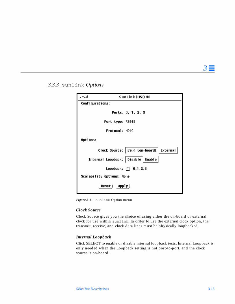
SBus Test Descriptions 3-15
3
3.3.3 sunlink Options
Figure 3-4 sunlink Option menu
Clock SourceClock Source gives you the choice of using either the on-board or externalclock for use within sunlink . In order to use the external clock option, thetransmit, receive, and clock data lines must be physically loopbacked.
Internal LoopbackClick SELECT to enable or disable internal loopback tests. Internal Loopback isonly needed when the Loopback setting is not port-to-port, and the clocksource is on-board.

3-16 SunDiag User’s Guide: Addendum for SMCC Hardware—November 1994
3
LoopbackThe Loopback cycle option specifies the loopback type. The choices are: simplesingle external port loopback, multiple external port loopback, and port-to-portexternal loopback.
3.3.4 sunlink Command Line Syntax
/opt/SUNWdiag/bin/sunlink [ device_name clock_source port#] p data_patterni loopback_type I k st standard_arguments
The following is a typical command line syntax for testing an HSI/S Sbus card:
Typing this at the command line will test port 0’s internal loopback.
Arguments
device_name Specifies the device to be tested.
hih HDLC and SDLC protocols
clock_source o On Board
e External
port# The port number to be tested. For example, hiho0. 0 is the portnumber.
pdata_pattern data_pattern is one of the following:
c Specifies character (0x55)
i Incrementing
d Decrementing
r Random.
I Enables internal loopback for HSI/S.
k Load DCP kernel
st Display sunlink status only
woodberry% /opt/SUNWdiag/bin/sunlink hiho0 I

SBus Test Descriptions 3-17
3
3.3.5 sunlink Quick Test Description
Running this test in quick mode abbreviates the test procedure. Normally, theinternal and external loop counts are set to 100. The internal loop count is setto 1 for the quick test; the external loop count remains at 100. Normally, thistest receives time-out checks every 600 seconds; in the quick test, it receives thechecks every 4 seconds.
3.3.6 sunlink Loopback Connectors
When selecting the SCP2 loopback assignments, the “To” port number isconnected to the “From” port shown directly above it. For example, in theoption menu shown above, ports 0 and 1 are looped, and ports 2 and 3 arelooped. If port 3 were not specified, ports 0 and 1 would be linked and port 2would be looped to itself:
From: 0, 2 To: 1
Refer to Appendix A of this manual, and the High Speed Serial Interfacehardware manuals for information on loopback connectors.

3-18 SunDiag User’s Guide: Addendum for SMCC Hardware—November 1994
3
3.4 Prestoserve Test (pstest )
3.4.1 pstest Test Description
Prestoserve is an NFS accelerator. It reduces the frequency of disk I/O accessby caching the written data blocks in non-volatile memory. Prestoserve thenflushes the cached data to disk asynchronously, as necessary. pstest verifiesPrestoserve’s functionality with the following three checks:
Board Battery CheckTo ensure proper battery power level, the test runs this check before runningthe other two checks. If it finds a bad battery, it exits pstest immediately witha “fatal error” message.
Board Memory CheckThis check maps the entire board memory to a process address space and locksthe board to prevent multiple accesses. The test then travels through themapped address spaces sequentially, doing a “char,” “short,” and “long”comparison on each. pstest executes this check twice.
Board Performance and File I/O Access CheckThis check exercises only synchronous read/write access. pstest writes dataequal to the amount of on-board memory to the memory cache and reads thedata back for comparison. The time taken to write that data is measured twice:the first time with Prestoserve disabled, the second time with Prestoserveenabled. The first value is divided by the second to get the performance ratio.If the ration is less than 1.5 on three passes of the test, the Prestoserve boardmay or may not have a problem.
Since Prestoserve accelerates the /opt partition during testing and thispartition may be mounted remotely, there may or not be a problem with thePrestoserve board itself; rather, a network performance problem could be theroot of the problem. In either case, a warning message is displayed if theperformance ratio is less than 1.5.

SBus Test Descriptions 3-19
3
Caution – To insure that consistent results are obtained, run as manyconcurrent tests as possible when a Prestoserve product has been installed.Tests are selected from the Option menu. The default is 2; the maximum is 10.However, do not enable pstest and kmem at the same time. Running thesetests together causes SunDiag to incorrectly report errors.
3.4.2 pstest Command Line Syntax /opt/SUNWdiag/bin/pstest l e standard_arguments
3.4.3 pstest Quick Test Description
Running pstest in quick mode changes the test algorithm as follows:
• Board Battery Check - No difference• Board Memory Check - The check will be executed once instead of twice.• Board Performance and File I/O Access Check - No difference
Arguments
l Enable long memory test.
e Enable performance warning, which will display a warningmessage if the performance ratio is less than 1.5.
!

3-20 SunDiag User’s Guide: Addendum for SMCC Hardware—November 1994
3
3.5 Serial Parallel Controller Test (spiftest )SunDiag uses the Serial Parallel Controller device driver to access the cardcomponents such as the cd-180 and ppc2 chips, and the serial and parallelports.
3.5.1 spiftest Hardware Requirements
Before running SunDiag system exerciser, make sure you install the cards to betested and the device driver. Also, you should reboot your system with theboot -r command to reconfigure the system and allow the SunDiag kernel torecognize the new driver.
The following minimum hardware configuration is required to successfully runthe Internal Test:
• SBus-based SPARC desktop system with an SBus slot.• Serial Parallel Controller card, installed in one of the SBus slots.
The following hardware is also required to successfully run the other SundiagSerial Parallel Controller tests:
• Serial Parallel Controller Patch panel (Part No. 540-2007).• 96-pin loopback plugs (Part No. 370-1366).• 25-pin serial loopback plugs (Part No. 540-1558).• RS-232 serial cables (Part No. 530-1685).• TTY terminal.
Note – spiftest must be run in intervention mode.

SBus Test Descriptions 3-21
3
Figure 3-5 spiftest Option Window
3-22 SunDiag User’s Guide: Addendum for SMCC Hardware—November 1994
3
3.5.2 spiftest Configurations
The Configurations: section displays the serial ports available for the SPC/Sboard. The available ports are as follows:
3.5.3 spiftest Options
96-pin Loopback (LB)This test provides data transmission, full-modem loopback, and parallel portloopback testing. You must attach a 96-pin loopback plug to the card under testbefore running this test (See Appendix A).
Internal TestThis test performs a quick internal check of the Serial Parallel Controllercard(s) installed in SBus slots. You do not need to attach anything to the card(s)to perform this test.
25-pin Loopback (LB)This test provides full-duplex transmission and full-modem loopback testing ofthe serial port selected in the Serial Port section of this menu. You must attacha 25-pin Loopback plug to the serial port on the patch panel that is being tested(See Appendix A). This test cannot be run concurrently with the Echo-TTYoption enabled.
Board Number Board Device Serial Ports Parallel Ports
0 stc0 term/0-7 printers/0
1 stc1 term/8-15 printers/1
2 stc2 term/16-23 printers/2
3 stc3 term/24-31 printers/3
4 stc4 term/32-39 printers/4
5 stc5 term/40-47 printers/5
6 stc6 term/48-55 printers/6
7 stc7 term/56-63 printers/7

SBus Test Descriptions 3-23
3
Parallel PrinterThis test sends the entire ASCII character set to a parallel printer. You mustattach a parallel printer to the parallel port on the Serial Parallel Controllerpatch panel. Observe the printer output to validate the test.
Echo-TTYThis test checks the proper operation of the serial port selected in the SerialPort section of this menu by echoing characters typed on a TTY terminalkeyboard to the TTY terminal screen. Type anything on your TTY keyboard,and the characters you type should show up on the TTY screen. If you do nottype anything, this test will eventually time-out. This test is terminated bypressing Control-C. After a short delay, the Status Window updates the PassCount. This test cannot be run concurrently with the 25-pin Loopback subtest.
Char SizeCharacter length; choose 5, 6, 7, or 8 characters.
Stop BitSpecifies the number of stop bits; choose 1 or 2 bits.
Baud RateSpecifies the baud rate; choose 110, 300, 600, 1200, 2400, 4800, 9600, 19200, or38400 baud.
Note – The baud rate of 38400 can only be used if one port is tested at a timeand the Internal Test is disabled.
ParitySpecifies the selectable parity; choose none , odd or even .
Flow ControlSpecifies the selectable flow control; can be XOnOff , rtscts , or both .

3-24 SunDiag User’s Guide: Addendum for SMCC Hardware—November 1994
3
Data TypeSpecifies the selectable data type pattern; can be 0x55555555, 0xaaaaaaaa, orrandom. 0x55555555 and 0xaaaaaaaa are abbreviated “0x55” and “0xaa” on theoption menu.
Serial PortSpecifies the serial port to be tested. The available ports are listed in theConfigurations section at the top of the spiftest options menu.
You can also change the test options by modifying the/opt/SUNWdiag /bin/.usertest file. See Section 1.8, “Adding Your OwnTests in .usertest ” in Chapter 1 of the SunDiag User’s Guide.
3.5.4 spiftest Command Line Syntax
/opt/SUNWdiag/bin/spiftest D= device_name T= subtest_number B= baud_rateC=character_length S= #of_stop_bits P= parity F= flow_control I= loopback_patternstandard_arguments
Arguments
D=device_name device_name is the device to be tested. There is no default; youmust type a device name. It can be either a board (sb1-8 ) or anindividual port (term/0 - term/63 ):
sb1 The 8 serial ports in the first card
sb2 The 8 serial ports in the second card
sb3 The 8 serial ports in the third card
sb4 The 8 serial ports in the fourth card
sb5 The 8 serial ports in the fifth card
sb6 The 8 serial ports in the sixth card
sb7 The 8 serial ports in the seventh card
sb8 The 8 serial ports in the eighth card
or
/dev/term/ mm
Where mm is 0 - 63 (any of the serial ports in SBus card slots)
SBus Test Descriptions 3-25
3
T=subtest_number subtest_number is one of the subtest options below. These arebinary representations of the test values. You can enter onevalue, or the sum of any combination. There is no default; youmust type a value:
1 Internal loopback test
2 Printer testNote: Requires parallel printer if run alone.
4 96-pin loopback test
8 DB-25 loopback test
16 Echo-TTY test
Here are two examples of subtest combinations:
10 Printer test with the DB-25 loopback test
18 Printer test with the Echo-TTY test
B=baud_rate baud_rate is one of 110, 300, 600, 1200, 2400, 4800, 9600, 19200, or38400. The default is 9600. To use the 38400 rate, only one portat a time can be tested, and the Internal Test must be disabled.
C=character_length character_length specifies a character length between 5 and 8.The default is 8 characters.
S=#of_stop_bits #of_stop_bits is the number of stop bits. The default is 1.
1 1 stop bit
2 for two stop bits
P=parity Parity. The default is none ; the options are:
none
odd
even
F=flow_control Flow Control Protocol. The default is rtscts .
xonoff Xon/Xoff
rtscts hardware flow control
both xonoff and rtscts
Arguments

3-26 SunDiag User’s Guide: Addendum for SMCC Hardware—November 1994
3
3.5.5 spiftest Quick Test Option
Running this test in quick mode restricts testing to the Internal Loopback Test.The internal loopback test performs a quick internal check of the Serial ParallelController card(s) installed in SBus slots. You do not need to attach anything tothe card(s) to perform the quick test.
3.5.6 spiftest Error Messages
These error messages are generated when the Sundiag Serial ParallelController discovers fatal errors. The error descriptions below identify possiblecauses for the card or test failure, and identify the Field Replaceable Unit(FRU), if possible. The three FRUs affected are: the Serial Parallel Controllercard, the 96-pin shielded cable, and the Patch panel.
This section also provides suggestions if an error is not hardware related.
No SPC/S card found or device driver not installed
An incorrect slot number was specified, or a non-SPC/S card was found, orthe device driver was not installed.
Ioctl STC_DCONTROL(STC_REGIOW-COR2) error on < device name>, or
Ioctl STC_DCONTROL(STC_REGIOR-CCR) error on < device name>, or
Ioctl STC_DCONTROL(STC_REGIOW-CCR) error on <device name>, or
Ioctl STC_DCONTROL(STC_PPCREGW-PDATA) error on < device name>, or
Ioctl STC_DCONTROL(STC_PPCREGR-PDATA) error on < device name>, or
Ioctl TCSETS failed on < device name>, or
I =loopback_pattern loopback_pattern is the loopback test data pattern.The default is a.
5 an 0x55555555 pattern
a an 0xaaaaaaaa pattern
r a random pattern
Arguments

SBus Test Descriptions 3-27
3
Ioctl TIOCMGET error on < device name>, or
Ioctl TIOCMSET error on <d evice name>, or
Ioctl STC_GPPC error on device < device name>, or
Ioctl STC_SDEFAULTS error on < device name>, or
Ioctl STC_DCONTROL error on < device name>
The device driver was not installed correctly, or the card is not working (seesystem console for messages). You may need to reinstall the device driver.
Expected DSR set, observed clearParallel port loopback test failed on < device name>
The modem lines DSR are not stable, or the parallel port is not sending thecorrect data, or the 96-pin loopback plug either is wired incorrectly or notmaking proper contact.
Expected < pattern>Observed < pattern>Modem loopback test failed on < device name>
The modem lines are not stable. If the modem loopback test passed on the96-pin loopback test and failed on the 25-pin loopback test, then it ispossible that either the patch panel or the cable is not functional. Also, makesure the loopback plug is making proper contact.
Can’t enable SP-96 when DB-25, Print or echo-tty testoption is selected!
The 96-pin loopback test was selected while an incompatible option (25-pinLoopback, Parallel Print, or Echo-TTY) was also chosen.
Can’t enable echo-tty when DB-25 or SP-96 test option isselected!
Echo-TTY test was selected while an incompatible option (25-pin or 96-pinloopback tests) was also chosen.
3-28 SunDiag User’s Guide: Addendum for SMCC Hardware—November 1994
3
Can’t enable Parallel Print when SP-96 test option isselected
The Parallel Print test was enabled while an incompatible option (25-pinLoopback test) was also chosen.
Can’t open < device name> with file descriptor <number>
This is an internal error. Contact Sun for technical assistance.
Device < device name> already open
Two tests are trying to access the same device at the same time or the deviceis already busy running another process.
Open error on < device name>, device driver may not beinstalled properly
The device driver is not installed, or not installed properly. When the SPC/Sboard is removed from a system, the device driver is unloaded at the nextboot. If the board is reinstalled, the device driver must then be reloadedwith the /usr/sys/unbundled/stc_config installation script.Otherwise, Sundiag will not recognize the board, or display spiftest asan option, and will return this error message.
Read error on < device name>, or
Write error on < device name>
Another application is currently using this device or there is a board error.
Paper out error on device < device name>,
The parallel printer may be out of paper, or there is no printer connected.Check the printer status.
Off-line error on device < device name>, orBusy error on device < device name>, orError on device < device name>
The parallel printer may be off-line, busy printing data, or some other errorcondition exists. Check the printer status.

SBus Test Descriptions 3-29
3
Expected < number> bytes, observed < number> bytesInternal test failed on < device name>
Data transmission failed because you’re running the internal loopback withanother test in . usertest mode, or there is a hardware error. The SerialParallel Controller card must be replaced.
Expected = < pattern>, observed = < pattern>Internal test failed on < device name>
Data transmission failed, the card must be replaced.
Expected = < pattern>, observed = < pattern>Data loopback failed on < device name>
Data transmission failed because you are running the internal loopback withanother test, or the loopback connector is not making proper contact, or thecard failed. Re-insert the connector and make sure it makes proper contact.If the test still fails and if you are running the 25-pin loopback test, you cantry to run the 96-pin loopback test to isolate the problem. If both tests fail forthe same port, then it is possible that the card is not functional. If the 96-pintest passes, and the 25-pin doesn’t, try the test with a different cable,loopback plug, or patch panel.
Timeout error on < device name>
The system is heavily loaded or has a large amount of swap spaceconfigured. Try running spiftest alone.
No loopback plug found on < device name>
Timeout error , ortty terminal is not connected to < device name>
No terminal is connected, or the Echo-TTY test has not been terminated witha Control-C.

3-30 SunDiag User’s Guide: Addendum for SMCC Hardware—November 1994
3
3.6 ZX Graphics Accelerator Test (leotest )SunDiag verifies the Sun Microsystems ZX Graphics Accelerator with asequence of subtests. All tests are nondestructive and maintain the systemintegrity during and after the tests are run.
Caution – Do not run any other application that uses the ZX accelerator portwhile running leotest . This combination will cause SunDiag to returnincorrect errors.
Note – leotest requires approximately 2.0 Mbytes of disk space in the /tmpdirectory to extract its working files. If this space is not available, thediagnostic will fail and report warning and error messages indicating lack ofdisk space.
By default, SunDiag runs all of the available tests, except the Stereo test. Seethe Test Descriptions section below.
Note – To avoid excessive test cycle times when testing the ZX GraphicsAccelerator, follow these instructions:
1. Enable Single Pass on the SunDiag Options menu.2. Enable Verbose on the SunDiag Options menu.3. Do not select any other diagnostic tests.
Following these procedures will ensure that leotest will run once, reportstatus as each test routine executes, and then exit.
Note – Disable all screen savers before testing any graphics device. Typexset s off at a UNIX prompt to disable the Solaris screen saver.
!

SBus Test Descriptions 3-31
3
Figure 3-6 leotest Option Window
3-32 SunDiag User’s Guide: Addendum for SMCC Hardware—November 1994
3
3.6.1 leotest Test Description
leotest is divided into two subtest categories: Direct Port Tests, andAccelerator Port Tests.
3.6.1.1 Direct Port Tests
The direct ports tests check the non-accelerated portion of the ZX using thefollowing subtests.
Video MemoryThe video memory array subtest selects and tests 64 by 64 pixel regionscovering all video memory planes, including the 24-bit double-buffered imageplane, 8-bit overlay plane, 24-bit depth (Z buffer) plane, and10-bit WID plane.If the subtest detects an error, SunDiag reports the defective plane andlocation.
LUTsThis subtest performs a non-destructive read-write test on the frame buffercolor look up tables and the window ID look up tables. After the test is done,the previous contents of these tables will be restored. If this subtest detects afailure, SunDiag reports the location of the failure.
At the beginning of this subtest, red, green, and blue stripes display for visualverification of the digital-to-analog converters (DACs).
Frame Buffer OutputThe Frame Buffer Output subtest creates various windows in the Window IDplane then sets up the look up tables (LUTs) associated with these windows.This subtest then writes random values to the video memory of thesewindows. Next, the test verifies the image RGB data of each pixel by triggeringthe trap registers, reading and generating RGB checksums from these values,and comparing these checksums with known values. This is also a visualcursor test as the cursor is being displayed for each pixel that is under test.
Caution – Moving the mouse cursor during the test will prolong the test, andmay cause failures. For best results, remove the mouse from the mouse padduring this test.!

SBus Test Descriptions 3-33
3
3.6.1.2 Accelerator Port Tests
The accelerator port test consists of a sequence of subtests which are designedto ensure the ZX Graphics Accelerator integrity at the system level. They takeas their inputs accelerator port transaction files. These files contain graphicdata which are passed to the ZX Accelerator port in groups of 32-bit wordscalled “packets.” These packets contain dots, vectors, triangles, and pass-through commands, and are generated in either immediate (programmed I/O)or DMA mode. The ZX SunDiag queries the system software for DMAcapability, and if applicable, will render objects in DMA mode for somesubtests. For more information on ZX hardware, please refer to the LeoHardware Reference Manual.
For verification, after the image is rendered to the frame buffer, each subtestreads the RGB image data from the frame buffer and compares the data againstknown good images. To save disk space, the good image data are stored in areduced size (64 times smaller that the normal size), and are stored in the Sunraster file format. The files are stored in the leotest.data file in/opt/SUNWdiag/bin .
Note – These subtests verify a frame buffer region of 1152 by 900 pixels,regardless of the size of the monitor attached to the system.
Microcode SRAM Checksum and Read/Write SelftestThis subtest sends a diagnostic package to the microcode of the Floating PointTransform engine to instruct it to reset the accelerator port, run the SRAMselftest, and restart the engine. Then it will verify each SRAM of all four LeoFloat chips in the Floating Point Transform engine to make sure they have thesame checksum. If not, it will report error using the information passing to itfrom the microcode. It also performs non-destructive read/write tests on eachSRAM.
PrimitiveThis subtest renders primitives such as dots and lines as well as triangles withdifferent color and shading at each vertex.

3-34 SunDiag User’s Guide: Addendum for SMCC Hardware—November 1994
3
VectorThis subtest renders fairly large vector objects with aliased and anti-aliasedvectors. This subtest will be rendered in DMA mode, when applicable.
Viewport ClippingThis subtest renders and clips an object around and in front on the screen.
Hidden SurfaceThis subtest renders objects with the Z-buffer-compare attribute turned on.
Polygon Edge HighlightingThis subtest renders an object with the polygon edge attribute turned on. Thissubtest will be rendered in DMA mode, when applicable.
TransparencyThis subtest renders a scene with two transparency modes (stand-alone andalpha blend) in various degrees. This results in a two-pass transparency of theobjects in the scene. This subtest will be rendered in DMA mode, whenapplicable.
Depth-CueingThis subtest renders an object with the depth-cueing attribute turned on.
Lighting and ShadingThis subtest renders an object with multiple light sources and Gouraudshading for front and back surfaces. This subtest will be rendered in DMAmode, when applicable.
Raster CopyThis subtest renders 32-bit image and various subregions of it, and zoom in ona subregion, using the microcode raster data copy command.
PickingThis subtest has two parts: a pick detect test and a pick echo test.

SBus Test Descriptions 3-35
3
XGLThe transaction file for this subtest was generated from an XGL program toensure that the XGL registers are exercised.
ArbitrationThis subtest continually renders an object into the accelerator port while asecond process performs a read-write test to the WID planes from the directport on the Frame Buffer. This subtest simulates conditions in the real world,where rendering processes and windows operation run concurrently. Thissubtest will be rendered in DMA mode, when applicable.
Stereo (Interactive)This subtest displays text information in stereo mode. The user verifies properoperation by looking at the screen with stereo glasses and following theinstructions being displayed.
3.6.1.3 ZX SunDiag Options
Loops per subtestType the number of times each test should be run before going on to the nexttest. The default is 1 loop.
Loops per test sequenceType the number of times the entire test sequence should be run. Eachsequence pass will register one in the SunDiag Pass Count window. Thedefault is 1 loop.
FB LockingSee the “Special Note on Testing Multiple Framebuffers” section in Chapter 1of the SunDiag 4.4 User’s Guide for details.

3-36 SunDiag User’s Guide: Addendum for SMCC Hardware—November 1994
3
PatternPress MENU to select a data pattern for use in the direct port tests. The defaultis “r” for random patterns. You may select a pattern of 0s, 3s, 5s, or 9s. Forexample, if you choose a pattern of 3s, the value 0x33333333 will be written toand read from the frame buffer.
3.6.2 leotest Command Line Syntax
/opt/SUNWdiag/bin/leotest D= device_name S= subtest_numberF=#_of_subtest_loops B= #_of_test_loops L standard_arguments
Arguments
D=devicename device_name is the full path name of the device under test.The default is /dev /fbs/leo0.
S=subtest_number subtest_number is the test number of the subtest to be run.Select from the subtests below. You can run multiplesubtests by adding the subtest numbers. For example,n=0x3 runs both test 1 and test 2; n=0x180 runs both test0x080 and test 0x0100. Note that you do not need theleading zeros. To run all tests, enter n=0xFFFF.0x 000 001 Direct port—video memory0x 000 002 Direct port—CLUTs and WID LUTs0x 000 004 Direct port--Frame buffer output section0x 000 008 Direct port--SRAM checksum &
Read/Write0x 000 010 Accelerator port —primitives0x 000 020 Accelerator port—vectors0x 000 040 Accelerator port—clipping0x 000 080 Accelerator port—z-buffer0x 000 100 Accelerator port—polygon edge0x 000 200 Accelerator port—transparency0x 000 400 Accelerator port—depth cueing0x 000 800 Accelerator port—lighting & shading0x 001 000 Accelerator port—raster copy0x 002 000 Accelerator port—picking0x 004 000 Accelerator port—XGL0x 008 000 Accelerator port—arbitration0x 010 000 Accelerator port—stereo (interactive)
F=#_of_subtest_loops #_of_subtest_loops is the number of loops for each subtest.The default is 1 (one loop)

SBus Test Descriptions 3-37
3
3.6.3 leotest Quick Test Description
Running this test in quick mode does not change the test procedure.
3.6.4 leotest Command Line Examples
Here are three examples illustrating how to run leotest from a commandline. Make sure to change the directory to /opt/SUNWdiag/bin beforerunning leotest from the command line. leotest is hard-wired to look forits data file, leotest.data , in /opt/SUNWdiag/bin .
1. A Simple accelerator port test, “primitive” single pass:
2. All direct port tests, five loops of sequence:
3. All subtests (except the interactive tests), two loops of each subtest, fourloops of each test sequence:
B=#_of_test_loops #_of_test_loops is the number of loops of each test sequence.The default is 1 (one loop).
L Disables framebuffer locking. See the “Special Note onTesting Multiple Framebuffers” in Chapter 1 of the SunDiag4.4 User’s Guide for details.
P=pattern_number Select a pattern number for use with the direct ports tests.The default is r , for random patterns. You may also choose0, 3, 5, or 9.
machine# cd /opt/SUNWdiag/binmachine# leotest S=0x10
machine# cd /opt/SUNWdiag/binmachine# leotest S=0x7 B=0x5
machine# cd /opt/SUNWdiag/binmachine# leotest S=0xFFFF F=2 B=4
Arguments (Continued)

3-38 SunDiag User’s Guide: Addendum for SMCC Hardware—November 1994
3
3.6.5 leotest Error Messages
The ZX SunDiag error messages are described below. The error messages arelisted in alphabetical order.
Arbitration test failed.
The arbitration test fails, and the cause is given in the following message.
Background process wouldn’t die. System error.
A software error. You may have to re-boot the SPARCstation.
Busy wait exceeded %d loops. Error in the Floating PointTransform section. Re-run Leoconfig.
A timeout error condition. Possibly there is a problem with the FloatingPoint Transform section, and the leoconfig software (located in/etc/opt/SUNWleo/bin/leoconfig ) should be executed again. Checkthe man pages on leoconfig for more details.
[Plane group name] Byte Access Mode error at x=%d y=%d,bank=#, expected=0x#x, observed=0x#n, XOR=0x#x.
The direct port video memory test has found an error at pixel (x,y) in thenamed plane group. The bank # refers to the corresponding VRAM banknumber. Byte/Stencil Access Mode applies to all plane groups that access 8bits of the frame buffer memory (in other words, the 8-bit image andoverlay planes). The test expected to find exp but observed obs, yielding xorwhen the two values are exclusive or’d with each other.
Note – The following error messages are software errors. They are groupedtogether because the cause of the errors is similar. The reason for the errors isdescribed at the end of the list.
Cannot read Window ID look up table from device [device].Check device for existence and/or permissions.
Cannot write Window ID look up table to device [device].Check device for existence and/or permissions.

SBus Test Descriptions 3-39
3
Cannot read Color LUTs from device [device]. Check devicefor existence and/or permissions.
Cannot post Color LUTs to device [device]. Check device forexistence and/or permissions.
Cannot get monitor mode from device [device]. Check devicefor existence and/or permissions.
Cannot set diagnostic mode from device [device]. Checkdevice for existence and/or permissions.
Cannot set monitor mode from device [device]. Check devicefor existence and/or permissions.
Cannot create raster for device [device]. Check device forexistence and/or permissions.
Cannot create color map for device [device]. Check devicefor existence and/or permissions.
Cannot create context for device [device]. Check device forexistence and/or permissions.
Cannot create color translation object for device [device].Check device for existence and/or permissions.
Cannot create path object for device [device]. Check devicefor existence and/or permissions.
Cannot create child raster for device [device]. Checkdevice for existence and/or permissions.
Cannot create multiple plane group information for device[device]. Check device for existence and/or permissions.
Software error. The device that you specified (the default is/dev/fbs/leo0 ) may not be available to the test, therefore the aboveoperation cannot be performed on this device. Make sure that you areexecuting the test on a machine with a ZX, and that you have permission toaccess it, and the device is not being used by another application.

3-40 SunDiag User’s Guide: Addendum for SMCC Hardware—November 1994
3
Cannot start another process. Software error.
Software error. The process table maybe full and the SPARCstation mayhave to be rebooted.
Cannot grab mouse or keyboard because [reason]. May need tobring down other graphic software that is currently runningsame window server.
Software error. When the FB locking option is selected, leotest also triesto lock the mouse and keyboard but not successful in doing so. The reasoncan be one of the followings, according the window system software:
mouse/keyboard is frozen
grab window is not viewable
grabbed at invalid time
already grabbed by another client
CLUT #n, index #, color [color], expected 0x#, observed0x#, XOR=0x#
An error was found in one the three color look up tables tested by SunDiag.The error was found in the nth CLUT. The index is out of 256 entries in eachCLUT. Each CLUT has eight bits value each for red, green, and blue. Thecolor indicates in which set of eight bits the error was found. The testexpected to find expected but received observed, yielding XOR when the twovalues are exclusive or’d with each other.
Data file [filename] missing in the current test directory.
Software error. ZX SunDiag can’t find the data file (leotest.data ) in thecurrent /opt/SUNWdiag/bin directory. May have to reinstall theSUNWdiag package in the specified directory.
Error in [subtest] test.
The subtest fails and the cause is given in the following message.

SBus Test Descriptions 3-41
3
Error in verifying the [Red/Green/Blue] plane at x=#,y=#,bank=#, expected=0x#,observed=0x#, XOR=0x#.
Failed accelerator port test. The error is in either the Red, Green, or Blueimage plane. The x-y coordinate of the pixel should contain expected valuebut observed value is received instead, yielding XOR value, or the bits inerror, when the two values are exclusive or’d with each other.
Failed to open data file [filename]. Suspect incomplete orincorrect hardware installation. Files may also have beencorrupted.
Indicates a software initialization problem. [filename] is the data file thatSunDiag can’t open.
Failed to read data file [filename]. Suspect incomplete orincorrect hardware installation. Files may also have beencorrupted.
Indicates a software initialization problem. [filename] is the data file thatSunDiag can’t read.
Illegal SBus DVMA code = 0x%x addr = 0x%x data= 0x%x. Maybedata file is corrupted.
Illegal SBus packet, code = 0x%x addr = 0x%x data = 0x%x.Maybe data file is corrupted.
This error occurs while the subtest is reading the transaction file. It is likelythat the data file is corrupted, so the SUNWdiag package may need to be re-installed.
Out of Memory.
Out of memory error. Increase swap space and/or kill other processes.
Pick Detect misses:%d lines and/or triangles inside thepickbox and/or %d lines and triangles outside the pickbox.
Failed the Picking accelerator port test. Only the failing component (RED,GREEN, or BLUE) appears in the message.

3-42 SunDiag User’s Guide: Addendum for SMCC Hardware—November 1994
3
Pick Echo failed: *** Error(s) found in [RED], [GREEN],[BLUE} components.
Failed the Picking accelerator port test. Only the failing component (RED,GREEN, or BLUE) appears in the message.
Picking: *** Error(s) found in [RED], [GREEN], [BLUE}components.
Failed the picking accelerator port test. Only the failing component (RED,GREEN, or BLUE) appears in the message.
[Plane group name] Pixel Access Mode error at x=# y=#,bank=#, expected=0x#,observed=0x#, XOR=0x#.
The direct port video memory test has found an error at pixel (x,y) in thenamed plane group. Pixel Access Mode applies to all plane groups thataccess the frame buffer memory four bytes at a time. (In other words, allplanes except eight bit planes). The memory for the pixel resides in thegiven VRAM bank. The test expected to find expected but observed observed,yielding XOR when the two values are exclusive or’d with each other.
SRAM checksum mismatch. Float #1 = 0x#, Float #2 = 0x#,Float #3 = 0x#, Float #4 = 0x#.
All four checksums of the SRAMs in the Floating Point Transform sectionare not identical. The subtest displays the mismatch checksum from eachSRAM of each LeoFloat chip.
SRAM of the LeoFloat [0/1/2/3], number of failures = #,first SRAM location = #, expected = 0x#, observed = 0x#,XOR = 0x#
An error is found in the SRAM test of the LeoFloat chip number 0, 1, 2, or 3.If the number of failures is more than 1, the subtest display the first SRAMlocation that fails, the expected and observed values in this location, and thebits in error (values of expected and observed are xor’d together).
‘tar’ never finished. System software problem.
Software error. Make sure that the tar program is installed correctly on yoursystem. Also, use df to see if you have enough disk space left in your /tmpdirectory.

SBus Test Descriptions 3-43
3
tar: [error]
Software error. Make sure that the tar program is installed correctly on yoursystem. Also, use df to see if you have enough disk space left in your /tmpdirectory.
TAR failed. Note: A space of approximately 2MB in /tmp isrequired for the test to run correctly.
Software error. The tar program cannot unpack data file to the /tmpdirectory because of not enough disk space.
The checksums for [red/green/blue] image data of all pixelsdon’t match, expected = 0x#, observed = 0x#, XOR = 0x#
The FB output section subtest prints out this message when the checksumsof either red, green, or blue image data observed from the trap registers in theVideo Output test are not the same as expected values. It also prints out theerror messages below if the upper four bits in the trap registers are notset/reset as expected,
The Even Field bit expected to be 0, observed 1.
The Composite Sync bit expected to be 1, observed 0.
The Composite Blank field expected to be 1, observed 0.
The Stereo bit expected to be 1, observed 0.
The Stereo bit expected to be 1, observed 0.
Either these bits are not set correctly or the read is from wrong location,which indicates there is an error in the Video Output section.
Unable to map (access) [device]. Not enough memory.
Software error. Cannot map the addresses for the ZX device (default/dev/fbs/leo0) because of not enough memory. May have to increase swapspace or add more memory.

3-44 SunDiag User’s Guide: Addendum for SMCC Hardware—November 1994
3
Unable to open device [device]. Check device for existenceand/or permission.
Software error. SunDiag is unable to open the ZX device. Make sure that/dev/fbs/leo0 exists and that the permissions are correct. There may be asoftware installation problem in which the ZX software packages need to bere-installed.
Uncompression of data file failed. Note: A space ofapproximately 2MB in /tmp is required for the test to runcorrectly
Software error. Not enough disk space in /tmp, about 2 Megabytes touncompress data file. You may have to remove unneeded files or link /tmpto a bigger disk partition.
Unknown data file magic number = 0x#.
Software error. The data file was generated by an older version of softwaretools. Report this error by filing a bug report or calling the Sun 800 number.
Unsupported 24-bit data length. Maybe data file iscorrupted.
This error occurs while the subtest is reading the transaction file. It is likelythat the data file is corrupted, so the SUNWdiag package may need to be re-installed.
Unable to open display. Window server not running.
Warning message only. This message is displayed when the ZX SunDiag isexecuted from the command line remotely or if SunDiag is run in TTYmode.
vfork: [error]
Software error. An error has occurred while trying to fork a child process.Increase swap space, or close other running processes.
[PWID/QWID] WLUT: Look up table error at index #, expected0x#, observed 0x#, XOR 0x#.
An error was found in either PWID (Hardware Window ID) or QWID(Software Window ID) look up tables tested by SunDiag. The error wasfound in the nth WLUT. The index is out of 64 entries for PWID or 15 for

SBus Test Descriptions 3-45
3
QWID. The test expected to find expected but received observed, yieldingXOR when the two values are exclusive or’d with each other, whichindicates the bits in error. This error message indicates there is an error inthe Video Output section.
3.7 NeWSprinter Test (spdtest )
3.7.1 spdtest Description
The spdtest is a two part test that checks the printer support hardware. Thefirst part is a register test that checks the NeWSprinter™ 20 SBus printer card’sinternal functions. The second part is a printing test that checks the interactionbetween the printer and the print server, as well as the printer’s owncapabilities.
3.7.2 spdtest Options
Figure 3-7 NeWSprinter Option Window

3-46 SunDiag User’s Guide: Addendum for SMCC Hardware—November 1994
3
Functional TestThe Functional test is composed of two subtests. The first subtest is theRegister test that checks the NeWSprinter 20 SBus printer card. The secondsubtest is the Printing subtest, which tests the printer’s capabilities.
The default setting is Register.
ResolutionThis exclusive setting defines the printer resolution of the printer test pattern.You can choose either 300 or 400 dots per inch.
The default setting is 300 dots per inch.
TrayFrom the Tray menu, you can choose from five different types of papercassettes:
• Main Tray (or Tray 1) is the top cassette that feeds paper to the printer.
• Tray 2 is the bottom cassette that feeds paper to the printer.
• Tray 3 is an optional tray.
• Manual Tray is a manual feed tray connected to the rear of the printer. Thistray is used to hand-feed print media which cannot be accommodated bythe paper cassettes.
• Auxiliary Feeder is optionally installed in place of the manual feed tray. TheFeeder stores and automatically feeds print media that would otherwiserequire the manual feed.
The default setting is the Main tray.
ModeFrom the Mode menu, you can set the interval between image printings. Thechoices are:
• Fast prints an image every 10 seconds.
• Medium prints an image every 12 minutes.
• Extended prints an image every 30 minutes.
The default setting is Fast.

SBus Test Descriptions 3-47
3
ImageThis option allows you to enter the filename of the test image to print.
3.7.3 spdtest Command Line Syntax
/opt/SUNWdiag/bin/spdtest F= function D=devicename L=loop R=resolution I= imageT=tray M=mode
Arguments
F=function The function value represents one of the following functionaltests:0 = Register test1 = Printing test
D=devicename The full pathname of the device must be substituted fordevicename.
L=loop Substitute Loop for the number of times you want to run thetest.
R=resolution Replace resolution with a number representing the printerresolution:0 = 300 dpi1 = 400 dpi
I= image Replace image with the name of a rasterfile.
T=tray The tray number represents the type of printer cassette theprinter uses:0 = Main tray (Tray 1)1 = Tray 22 = Tray 3 (optional)3 = Manual Tray4 = Auxiliary Feeder (optional)
M=mode The mode number represents how often to print the testimage:0 = Fast (Prints an image every 10 seconds)1 = Medium (Prints an image every 12 minutes)2 = Extended (Prints an image every 30 minutes)

3-48 SunDiag User’s Guide: Addendum for SMCC Hardware—November 1994
3
3.8 SunVideo Test (rtvctest )The rtvctest verifies the functionality of the SunVideo™ SBus card.SunVideo technology captures and compresses video input in real-time,making it possible to have real-time video conferencing over standard Ethernetnetworks.
3.8.1 rtvctest Test Description
The rtvctest is divided into four sub-tests: PROMCheck, memory, Jalapeno,and CL4000. The PROMCheck sub-test verifies the SunVideo card’sprogrammable read only memory. The memory test verifies all of the memoryon the card, including the 2 Mbytes of memory on the CL4000 compressionengine and the memory on the Jalapeno application-specific integrated circuit(ASIC). The Jalapeno sub-test verifies the interface logic between the SBus,A/D conversion chips, and the CL4000 compression engine. The CL400 sub-test verifies that the compression engine ASIC is able to compress digitizedvideo data from the A/D chips and send this data to the SBus, through theJalapeno ASIC.
The rtvctest is composed of 49 verification test modules. Table 3-3 lists thesemodules and their associated test sequence numbers.
Table 3-3 rtvctest Verification Modules
SunVideo Verification Module Name Test Sequence Number
RTVC SUNDIAG Start 0
RTVC Checksum 1
RTVC Jalapeno SMEM 2
RTVC CL4000 DMEM 3
RTVC Jalapeno SBus Interrupt Mask 4
RTVC CL4000 Interrupt Mask 5
RTVC DVMA Control Register 6
RTVC DVMA Transfer Size Counter 7
RTVC DVMA Memory Address Counter 8
RTVC DVMA Virtual Memory Address Counter 9
RTVC DVMA Slave SBus Rerun Register 10

SBus Test Descriptions 3-49
3
RTVC IIC Control Register 11
RTVC IIC Data Register 12
RTVC Video DMA Control Register 13
RTVC Video DMA Transfer Size Counter 14
RTVC Video DMA Memory Address Counter 15
RTVC User Interrupt 0 16
RTVC User Interrupt 1 17
RTVC User Interrupt 2 18
RTVC User Interrupt 3 19
RTVC Video Control and Status Register 20
RTVC Video Control Field Line Interrupt 1 21
RTVC Video Control Field Line Interrupt 2 22
RTVC Video Scan Line Mask Registers 23
RTVC Video Input Format Type 25
RTVC Video Horizontal Lock 26
RTVC Video Even Odd Field 27
RTVC CL4000 Host Control 28
RTVC CL4000 Host Lock 29
RTVC CL4000 Video Port A Control 30
RTVC CL4000 Video Port B Control 31
RTVC CL4000 Video Port A FIFO 32
RTVC CL4000 Video Port B FIFO 33
RTVC CL4000 Address Memory Registers 34
RTVC CL4000 Instruction Memory Access Registers 35
RTVC Time Stamp Register 36
RTVC CL4000 Register Memory 37
RTVC CL4000 Scratch Memory 38
Table 3-3 rtvctest Verification Modules (Continued)
SunVideo Verification Module Name Test Sequence Number

3-50 SunDiag User’s Guide: Addendum for SMCC Hardware—November 1994
3
3.8.2 rtvctest Options
Figure 3-8 rtvctest Option Window
RTVC CL4000 DMA Mode 39
RTVC CL4000 Motion Estimation Registers 40
RTVC CL4000 PSW 41
RTVC CL4000 Variable Length Coder Registers 42
RTVC CL4000 Channel Memory Registers 43
RTVC CL4000 CPU Control 44
RTVC CL4000 Multiply Control 45
RTVC CL4000 DMA Interrupt Control 46
RTVC CL4000 Block Transfer Mode 47
RTVC CL4000 Accumulator MSB 48
RTVC CL4000 JPC Field 49
RTVC SUNDIAG Finish 50
Table 3-3 rtvctest Verification Modules (Continued)
SunVideo Verification Module Name Test Sequence Number

SBus Test Descriptions 3-51
3
You may test the SunVideo card without any video device (camera, video discplayer, or VCR) connected to a input port. However, if you connect a videodevice to the card, then you must state the format of the video source and theinput port which the device is connected.
Note – If you do not state both the video source and the input port, thertvctest will print an error and terminate testing.
Source FormatSelect the format of the video source used for testing. You may select from thefollowing sources:
PortsIf you have selected a video source for testing, then you must state which inputport you have used to connect the source to the SunVideo card. You may selectfrom the following ports:
Video Source Definition
None No video source.
NTSC A National Television System Committee (NTSC) video source,which is the video standard in the United States and Japan.
PAL A phase alternate line video source, which is the video standard inEurope.
Input Port Definition
None No input port used.
CV1 The Composite Video Input Port 1 (RCA type input).
CV2 The Composite Video Input Port 2 (RCA type input).
SVHS The Super VHS input port.
3-52 SunDiag User’s Guide: Addendum for SMCC Hardware—November 1994
3
3.8.3 rtvctest Command Line Syntax
/opt/SUNWdiag/bin/rtvctest [ntsc | pal] [cv1 | cv2 | svhs] D= rtvc_device
3.8.4 rtvctest Quick Test Description
Running this test in quick mode abbreviates the test procedure. The quickmode test performs a subset of the available test modules, which shouldprovide a quicker check of the SunVideo hardware.
3.8.5 rtvctest Error Messages
SunVideo Error Message #10
%s
Where:
%s is one of the following message:
Missing REQUIRED argument D=rtvc[0..31]
Arguments
[ntsc | pal] Select the format of the video source used for testing. Selecteither ntsc (video standard in the United States and Japan)or pal (video standard in Europe).
[cv1 | cv2 | svhs] If you have selected a video source for testing, then youmust state which input port you have used to connect thesource to the SunVideo card. You may select from thefollowing ports:
cv1 Composite video input port 1 (RCA type)cv2 Composite video input port 2 (RCA type)svhs Super VHS port
D=rtvc_device You are required to state the SunVideo device when runningthe rtvctest from the command line. Replace rtvc_device withrtvc n, where n is the device number (from 0 to 31) of theSunVideo card under test.

SBus Test Descriptions 3-53
3
SunVideo Error Message #20
%s Error # %d
Where:
%s is one of the following message:
ioctl RTVC_CMD_RESET fault
ioctl RTVC_CMD_SET_VIDEO fault
ioctl RTVC_CMD_GET_VIDEO fault
open /dev/rtvc fault
close /dev/rtvc fault
open /dev/rtvcctl fault
close /dev/rtvcctl fault
Unknown Jalapeno Version
%d is one of the following number:
ioctl error
module version

3-54 SunDiag User’s Guide: Addendum for SMCC Hardware—November 1994
3
SunVideo Error Message #30
%s1 %s2 Error # %d
Where:
%s1 is one of the following message:
memory map fault for
memory unmap fault for
selected /dev/rtvc and /dev/rtvcc1 not available
%s2 is one of the following message:
prom
sram
buses
reset
dmem
rtvc
%d is the error number
SunVideo Error Message #40
RTVC Fault Detected via module %s1Physical Address %X Expected Value %X Actual Value %XRTVC Sundiag Module number %dLocation %s2Message: %s3
Where:
%s1 is the name of the module under test
%X are the values associated with physical address, expected value, actualvalue
%d is the Sundiag Module under test
%s2 is the U location of the faulty component
%s3 are any additional messages

SBus Test Descriptions 3-55
3
SunVideo Error Message #41
RTVC Fault Detected via module %s
Where:
%s is the name of the module under test
SunVideo Error Message #42
%s1 %X1 %s2 %X2
Where:
%s1 is one of the following message:
Video Format Expected
Video Port Expected
%X1 is the expected value
%s2 is one of the following message:
Actual
%X2 is the actual value
SunVideo Error Message #50
%s %d
Where:
%s is one of the following message:
Unknown RTVC CL4000 test module
Unknown RTVC Jalapeno test module
Unknown RTVC test module
Unknown RTVC memory test module
Unknown Start Bit
%d is the module number or start bit location

3-56 SunDiag User’s Guide: Addendum for SMCC Hardware—November 1994
3
RTVC Verbose Information #10
%s
Where:
%s is one of the following message:
Video Format OR Port NOT Selected - Test Skipped
Probe module : NOT XQT under SUNDIAG
Probe module : XQT under SUNDIAG
RTVC Verbose Information #20
%s1 %s2 Status %X
Where:
%s1 is one of the following message:
Finished
Started
%s2 is one of the following message:
Module Name
Sundiag
Walking One
Walking Zero
Data Line
Address Line
Stuck At Fault
Modulus 3
Read Write Collision
%X is fault detected flag

SBus Test Descriptions 3-57
3
RTVC Verbose Information #30
Executing module %d %s
Where:
%d is the test module number
%s is the test module name
3.9 PCMCIA Modem Card Test (pcmciatest )This test verifies the functionality of the PCMCIA Modem Card.
3.9.1 pcmciatest Test Description
The pcmciatest issues a series of commands to the modem which instructsthe modem’s firmware to run an internal analog loopback diagnostic test.Upon completion, the firmware sends back a three digit status messageindicating whether the test passed or failed.
As an option, the pcmciatest will test socket I/O cards. This test will writean 8 Kbyte incrementing data pattern to the I/O card which is then loopedback, read, and verified.
Note – When testing socket I/O cards, a 9-pin loopback connector is required.However, no loopback connector is required when testing the default modemcard. See Appendix A, “Loopback Connectors,” for loopback connector wiringinstructions.

3-58 SunDiag User’s Guide: Addendum for SMCC Hardware—November 1994
3
3.9.2 pcmciatest Options
Figure 3-9 pmciatest Option Window
The default card type for each PCMCIA slot is a modem card. If only onemodem card is plugged in, the empty slot will be ignored.
From the pcmciatest Option Window, you can choose to test socket I/Ocards. To test a socket card, choose socket on the Card Type switch. If youchoose to test a socket I/O card in an empty slot, the test will fail.
Any combination of modem and socket I/O cards may be placed in thePCMCIA slots. However, you must select the correct type of card in the OptionWindow. If you select an incorrect card type, the test will fail.
SBus Test Descriptions 3-59
3
3.9.3 pcmciatest Command Line Syntax
/opt/SUNWdiag/bin/pcmciatest o= card_type t= card_type
3.10 Infrared Interface Test (irtest )The irtest tests the SPARCstation Voyager™ system’s infrared (IR) interface.
3.10.1 irtest Test Description
The irtest is a two part test: a loopback test and an IR transmit test. In theloopback test, the irtest will send and receive an 8 Kbyte incrementing datapattern through an internal loopback within the Multi-Interface Chip’s (MIC)Serial Communication Controller (SCC).
In the second part of the test, the irtest will enable the IR transmitter andreceiver. The IR mode will be set to PULSE and the baud rate will be set to115200. The test will then send the same 8 Kbyte data stream (broken up into64 byte blocks) out the transmitter, allowing each byte to be detected and readby the receiver. The test will be repeated with the receiver disabled to makesure that the receiver does not pick up any data coming out of the transmitter
Note – The 8 Kbyte data is broken up into 64 byte blocks because this blocksize is the maximum amount of data that can be transmitted through the IRinterface without errors.
Arguments
o=card_type Specify the card type for slot 1 (o is short for “one”).card_type is the type of card in slot 1. Type o=s if there is asocket I/O card in slot 1.If there is a modem card in slot 1, then you do not need tospecify this argument.
t= card_type Specify the card type for slot 2 (t is short for “two”).card_type is the type of card in slot 1. Type t=s if there is asocket I/O card in slot 2.If there is a modem card in slot 2, then this argument is notneeded.

3-60 SunDiag User’s Guide: Addendum for SMCC Hardware—November 1994
3
Currently, only the PULSE mode is tested by the irtest. The error rate for HIGHmode is too high to permit this type of IR loopback testing.
3.10.2 irtest Options
Figure 3-10 irtest Option Window
The irtest currently has no options.
3.10.3 irtest Command Line Syntax/opt/SUNWdiag/bin/irtest

SBus Test Descriptions 3-61
3
3.11 SPARCstorage Array Controller Test (plntest )The plntest test checks the controller board on the SPARCstorage™ Array.
3.11.1 plntest Test Description
The SPARCstorage Array (SSA) is a large disk storage I/O subsystem capableof housing up to 30 SCSI hard drives. The SSA communicates with a hostsystem over a fiber optic link provided by an SBus-based host adapter card inthe host system and the corresponding SSA Controller board hardware.
The SSA Controller card is an intelligent, CPU-based board with its ownmemory and ROM-resident software. In addition to providing acommunications link to the disk drives, it also buffers data, between the hostsystem and disk drives, in its non-volatile RAM (NVRAM). In order for data togo from the host to a particular disk, it must first be successfully transferred tothis NVRAM space.
To perform this data transfer operation, the host machine, SBus host adaptercard, fiber-channel connection, and the SSA controller board must be workingproperly. It is precisely this operation that plntest tries to stress and verify.By stressing this operation, plntest can isolate failures on the SSA disk drivesfrom failures on the SSA Controller board.
Note – fstest and rawtest will transfer data on the SSA disk drives over thesame path mentioned above. However, they will not be issuing these datatransfers as quickly as plntest can.
plntest Stress TestThe plntest attempts to stress the SPARCstorage Array hardware andsoftware by issuing a large number of transfers between the host system andthe SSA controller board.
The plntest exercises the hardware and software by invoking many SCSIread buffer and write buffer commands, of various sizes and data patterns, tothe NVRAM. These operations exercise the host fiber channel hardware, theSSA fiber channel hardware, the SSA resident management software (PMF),and the hardware component interaction on the SSA controller card (allcomponents except the SCSI ones).

3-62 SunDiag User’s Guide: Addendum for SMCC Hardware—November 1994
3
3.11.2 plntest Options
Figure 3-11 plntest Option Window
ConfigurationsThe Configuration area lists the names of all the logical disk drives (both singleand grouped) that are attached to the SSA controller board.
Note – If no disks are present, the window will display “none” under theAttached Disks heading.

SBus Test Descriptions 3-63
3
Plntest ModeBy default, plntest is run in read-only mode, in which the test simply readsblocks of memory from the SSA controller.
Click on the Write/Read choice to enable the Write/Read test mode. InWrite/Read mode, plntest writes data (as specified by the Pattern optionbelow) to the SSA controller memory. This data is then read back andcompared.
Plntest PatternThe Pattern option allows you to specify the exact data pattern that will bewritten to the SSA memory. The data pattern choices are: 0’s. 1’s, 5’s, a’s, andRandom. Random is the default data pattern.
Plntest Buffer SizeThe Buffer size determines the size of the data transfers between the SSAcontroller card and the host system. The buffer size choices are: 1, 2, 5, 10, 50,100, 200, 500, or Random Kbytes. The default Random size selects buffer sizesbetween 1 and 500 Kbytes per transfer.
Note – plntest is not a scalable test.
3.11.3 plntest Command Arguments
/opt/SUNWdiag/bin/plntest ? D= device_name x W P= pattern B= buffer_size Kb
standard_arguments
Arguments
? Probes the system for valid SSA Controller devices and prints themto screen (see Section 3.11.3.1, “Probing for SSA Controller Devices.”)
D=device_name The physical pathname of the SSA controller card to be tested. Thisargument must be included when running plntest from thecommand line, unless the ? argument is used.

3-64 SunDiag User’s Guide: Addendum for SMCC Hardware—November 1994
3
3.11.3.1 Probing for SSA Controller Devices
Unlike most other hardware devices, the SSA controller card has not yet beenassigned a logical device name (one you would find in the /dev directory).Therefore, the SSA controller card is identified by its longer, physical devicename.
When running plntest from the command line, the physical device name of theSSA controller card must be specified. To avoid typing the long physical devicename, use the ? option. The ? option will probe the system and print out thephysical paths of all the attached SSA controller devices.
x Probes the specified SSA controller card for the single and groupeddisks attached to the controller card, and prints their logical namesto the screen.Note: The D=device_name must be specified for this option to work.
W Invoke the test in Write/Read mode. The default mode is read-only.Note: The D=device_name must be specified for this option to work.
P=pattern Choose the data pattern used in Write/Read mode. Choose one ofthe following data patterns:
a all A’s (hexadecimal)0 all 0’s1 all 1’s5 all 5’sr Random
Note: The D=device_name and W arguments must be specified to makethis option work.
B=buffer_size Kb Size of the buffer, in Kbytes, that will be transferred to and from thehost per test iteration. The buffer size can range from 1 to 500Kbytes, or r for random (default).Note: The D=device_name must be specified for this option to work.
Arguments (Continued)

SBus Test Descriptions 3-65
3
If you are going to invoke plntest from the command line often, it maybecome bothersome to type the physical device name each time. However, youcan create your own logical name and link it to the physical name. You willthen be able to invoke plntest with the shorter logical name.
3.11.4 plntest Quick Test Description
In quick test mode, the plntest will limit itself to 500 data transfers betweenthe host and the SSA.
3.11.5 plntest .usertest File Command Line
The following is a sample .usertest command:
3.11.6 plntest Error Messages
Unable to determine physical pathname for %s
Error in Closing device: %d
Error. Data Mismatch in Controller Memory
Error in validating device name
Can’t open /dev/dsk directory
machine# ./plntest “?”
1: /devices/io-unit@f,e3200000/sbi@0,0/SUNW,soc@1,0/SUNW,pln@0c0d,0e0f0102:ctlr2: /devices/io-unit@f,e0200000/sbi@0,0/SUNW,soc@3,0/SUNW,pln@0c0d,0e0f0102:ctlr
machine# ln -s \/devices/io-unit@f,e3200000/sbi@0,0/SUNW,soc@1,0/SUNW,pln@0c0d,0e0f0102:ctlr \/dev/ssa1machine# /opt/SUNWdiag/bin/plntest D=/dev/ssa1
pln0, plntest, D=/dev/pluto0 W P=r B=r

3-66 SunDiag User’s Guide: Addendum for SMCC Hardware—November 1994
3
Invalid device name
No Pluto Controller device specified. Use ‘D=’ option
No Pluto Controller devices found
No disks found on this Pluto Controller
Error in Opening device: %d
Error trying to probe device: %d
USCSI Read Buffer Error. USCSI ioctl() return %d
SCSI command to pln:ctlr failed. status = 0x %x
USCSI ioctl error. ioctl() return %d
USCSI Write Buffer Error. USCSI ioctl() return %d

4-1
User Test Descriptions 4
This chapter describes SunDiag tests for hardware devices that SunDiag willnot automatically detect during the device probe at start-up. Therefore, thesetests do not appear on the SunDiag control or status panels, even though theyare included in the /opt/SUNWdiag/bin directory.
There are two ways to run these tests: you can either create a .usertest file,or run each test individually from a command line. See “Adding Your OwnTests in .usertest ” in Chapter 1 of the SunDiag User’s Guide for details oncreating a .usertest file.

4-2 SunDiag User’s Guide: Addendum for SMCC Hardware—November 1994
4
4.1 SunDials Test (sundials )
4.1.1 sundials Test Description
From a .usertest FileThis test verifies that the SunDials™ graphics manipulation device controls areworking properly. sundials also verifies the connection between the dialboxand serial port.
Here is an example of a .usertest entry for sundials :
From a Command LineRunning sundials from a command line starts an interactive test thatdisplays a screen representation of the dialbox. You can move each of the dialsand see the corresponding dial’s display change. To run the interactive test,select the Diagnostics Button on the top of the window representation. Thedialbox dials on the screen will not move while the diagnostics test is running
Be certain that the dialbox is connected to one of the serial ports, and that thedialbox is complete with a power transformer to power it.
There is no option menu for this test.
4.1.2 sundials Command Line Syntax/opt/SUNWdiag/bin/sundials diag standard_arguments
4.1.3 sundials Quick Test Description
Running this test in quick mode does not change the test procedure.
bd,sundials,s
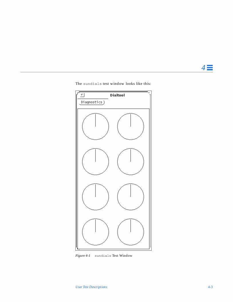
User Test Descriptions 4-3
4
The sundials test window looks like this:
Figure 4-1 sundials Test Window

4-4 SunDiag User’s Guide: Addendum for SMCC Hardware—November 1994
4
4.1.4 sundials Error Messages
Sundials O.K.
The test successfully completed
Cannot open device.
The device was probably not connected to the serial port.
ioctl(VUIDSFORMAT, VUID_NATIVE) -- you may need to rundbconfig.
dbconfig was probably not run and the test is getting an ioctl errorwhen trying to access the device.
No Response from Dialbox
The dialbox is connected properly, but it may not be getting power from thetransformer.
Selftest Failed
The dialbox selftest failed.

User Test Descriptions 4-5
4
4.2 SunButtons Test (sunbuttons )
4.2.1 sunbuttons Test Description
This test verifies that the SunButtons™ graphics manipulation device isworking correctly.
From a .usertest FileIn the non-interactive mode (from a .usertest file) this test verifies that eachbutton functions. You will see each button light up in a round-robin fashion.
From a Shell Command LineThis is an interactive test. The test will display a screen representation of thebuttonbox where you can press each of the buttons and see the correspondingbutton’s display change. To run the diagnostic test, select the DiagnosticsButton on the top of the window representation. The buttonbox buttons on thescreen will not change while the diagnostics test is running.
To run the test, select the Diagnostics button. As the test runs, you will see eachbutton light in a “round-robin” fashion.
Be certain that the buttonbox is connected to one of the serial ports, and thatthe buttonbox is complete with a power transformer to power it.
There is no option menu for this test.
4.2.2 sunbuttons Command Line Syntax/opt/SUNWdiag/bin/sunbuttons diag standard_arguments
4.2.3 sunbuttons Quick Test Description
Running this test in quick mode does not change the test procedure.

4-6 SunDiag User’s Guide: Addendum for SMCC Hardware—November 1994
4
The sunbuttons test window looks like this:
Figure 4-2 sunbuttons Test Window

User Test Descriptions 4-7
4
4.2.4 sunbuttons Error Messages
Sunbuttons O.K.
The test successfully completed
Cannot open device
The device was probably not connected to the serial port.
ioctl(VUIDSFORMAT, VUID_NATIVE You may need to rundbconfig.
dbconfig was probably not run and the test is getting an ioctl errorwhen trying to access the device.
No Response from buttonbox
The buttonbox is connected however it may not be getting power from thetransformer.
Selftest Failed
The Buttonbox selftest failed.

4-8 SunDiag User’s Guide: Addendum for SMCC Hardware—November 1994
4

A-1
Loopback Connectors A
These loopback connectors are designed to be used with the tests described inthis Addendum. See Appendix B of the SunDiag User’s Guide for moreloopback connectors.
Most of the loopback connectors described in this appendix are available fromSun; the part numbers are given where applicable. To obtain a loopbackconnector kit, contact Sun Customer Support.

A-2 SunDiag User’s Guide: Addendum for SMCC Hardware—November 1994
A
A.1 96-Pin Loopback ConnectorThis 96-pin connector can be ordered from Sun Microsystems(Part Number 370-1366).
Connect: pins 4 and 12 to pin 77pin 5 to pin 20pin 6 to pin 36pin 7 to pin 44pin 10 to pin 11pin 13 to pin 16pin 14 to pin 15pin 18 to pin 19pin 21 to pin 24pin 28 to pin 60pin 29 to pin 68pin 30 to pin 34pin 37 to pin 40pin 38 to pin 39pin 42 to pin 43pin 45 to pin 48pin 46 to pin 47pin 52 to pin 78pin 53 to pin 55pin 54 to pin 75pin 58 to pin 59pin 61 to pin 64pin 62 to pin 63pin 66 to pin 67pin 69 to pin 72pin 76 to pin 79pin 82 to pin 83pin 85 to pin 88pin 86 to pin 87pin 90 to pin 91pin 93 to pin 96pin 94 to pin 95
Female
Materials:PCR-E96FA (1)PCS-E96LKPA (1)3751 Metal Plug (1) (9563K42)AWG28 Madison Cable (8” long) UL/CSA Approved
1
48
49
96
45
12
20
77

Loopback Connectors A-3
A
A.2 96-Pin Loopback ConnectorThis 96-pin connector can be ordered from Sun Microsystems(Part Number 370-1381).
Connect: pin 3 to pin 4pin 5 to pin 7pins 8 and 9 to pin 12pin 10 to pin 11pin 13 to pin 14pin 15 to pin 17pins 18 and 19 to pin 22pin 20 to pin 21pin 27 to pin 28pin 29 to pin 31pins 32 and 33 to pin 36pin 34 to pin 35pin 37 to pin 38pin 39 to pin 41pins 42 and 43 to pin 46pin 44 to pin 45pin 51 to pin 52pin 53 to pin 55pins 56 and 57 to pin 60pin 58 to pin 59pin 61 to pin 62pin 63 to pin 65pins 66 and 67 to pin 70pin 68 to pin 69pin 75 to pin 76pin 77 to pin 79pins 80 and 81 to pin 84pin 82 to pin 83pin 85 to pin 86pin 87 to pin 89pins 90 and 91 to pin 94pin 92 to pin 93
Female Special
Materials:PCR-E96FA (1)PCS-E96LKPA (1)9563K999 Cap (1)Madison Cable (6” long) (#28 SCSI UL/CSA Approved)
1
48
49
96
3
12
4
Open Contacts:1, 2, 6,16, 23, 24, 25, 26, 30, 40, 47, 48, 49, 50, 54, 64, 71, 72, 73, 74, 78, 88, 95, 96
89

A-4 SunDiag User’s Guide: Addendum for SMCC Hardware—November 1994
A
A.3 37-Pin RS-449 Loopback CableUse these wiring instructions for a loopback cable for two 37-pin RS-449synchronous ports.
Figure A-1 37-Pin RS-449 Loopback Cable
1
2
3
4
5
6
7
8
9
10
11
12
13
14
15
16
17
18
1920
21
22
23
24
25
26
27
28
29
30
31
32
33
34
35
36
37
Connect: pin 4 to pin 6pin 7 to pin 9pin 8 to pin 17pins 11 and 12 to pin 13pin 22 to pin 24pin 25 to pin 27pin 26 to pin 35pins 29 and 31 to pin 30
1
2
3
4
5
6
7
8
9
10
11
12
13
14
15
16
17
18
1920
21
22
23
24
25
26
27
28
29
30
31
32
33
34
35
36
37
Male Male

Loopback Connectors A-5
A
A.4 37-Pin RS-449 Loopback PlugUse these wiring instructions for making a male 37-pin RS-449 loopback plug.This connector is also available from Sun (Part Number 530-1430).
Figure A-2 37-Pin RS-449 Loopback Plug
Connect: pin 4 to pin 6pin 7 to pin 9pin 8 to pin 17pin 11 to pin12pin 22 to pin 24pin 25 to pin 27pin 26 to pin 35pins 29 to pin 30
1
2
3
4
5
6
7
8
9
10
11
12
13
14
15
16
17
18
1920
21
22
23
24
25
26
27
28
29
30
31
32
33
34
35
36
37
Male

A-6 SunDiag User’s Guide: Addendum for SMCC Hardware—November 1994
A
A.5 9-pin Single-port Loopback PlugUse these wiring directions for male 9-pin RS-232 and RS-423 single-portloopback plugs:
Figure A-3 9-Pin Single-port Loopback Plug
1
2
3
4
5
6
7
8
9Connect: pin 2 to pin 3
pin 1 to pin 4 and pin 6pin 7 to pin 8
Male

Loopback Connectors A-7
A
A.6 9-pin Single-port Loopback PlugUse these wiring directions for female 9-pin RS-232 and RS-423 single-portloopback plugs:
Figure A-4 9-Pin Single-port Loopback Plug
Note – Use this loopback plug with the pcmciatest .
1
2
3
4
5
6
7
8
9Connect: pin 2 to pin 3
pin 1 to pin 4 and pin 6pin 7 to pin 8 and pin 9
Female

A-8 SunDiag User’s Guide: Addendum for SMCC Hardware—November 1994
A
A.7 9-Pin to 25-Pin Port-to-Port Loopback CableUse these wiring directions for a 9-pin RS-232 and RS-423 port to 25-pin RS-232and RS 423 port loopback cables. Both connectors are male.
Figure A-5 9-Pin to 25-Pin Port-to-Port Loopback Cable
1
2
3
4
5
6
7
8
9
Connect:First SecondConnector to Connector
pin 2 pin 2pin 3 pin 3pin 8 pin 4pin 7 pin 5pin 5 pin 7pin 4 pins 6 and 8pins 1 and 6 pin 20
1
2
3
4
5
6
7
8
9
10
11
12
1314
15
16
17
18
19
20
21
22
23
24
25
Male Male

Loopback Connectors A-9
A
A.8 9-Pin to 9-Pin Port-to-Port Loopback CableUse these wiring directions for 9-pin RS-232 and RS 423 port to 9-pin RS-232and RS-423 port loopback cables. Both connectors are male.
Figure A-6 9-Pin to 9-Pin Port-to-Port Loopback Cable
Please note that this cable has no Sun part number assigned to it.
A.9 NT to TE Loopback CableUsing two standard RJ45 connectors, and connect pin1 to pin1, pin 2 to pin 2,etc... for all pins. This loopback is a “straight-through” connection.
1
2
3
4
5
6
7
8
9
Connect:First SecondConnector to Connector
pins 1 and 6 pin 4pin 2 pin 3pin 3 pin 2pin 4 pins 1 and 6pin 5 pin 5pin 7 pin 8pin 8 pin 7
1
2
3
4
5
6
7
8
9
Male Male
A-10 SunDiag User’s Guide: Addendum for SMCC Hardware—November 1994
A

Index-1
Index
Aaudbri SpeakerBox test, 2-2
Bbi-directional parallel port printer
test, 3-2boot -r command, 1-2bpptest SBus printer card test, 3-2
CC30 chip, 2-38cg12 cgtwelve framebuffer test, 2-38cg14test cg14 framebuffer test, 2-46cg6test cgsix framebuffer test, 2-33CPU Tests
Pixel Processor test, 2-63CPU tests
cg12 cgtwelve framebuffer test, 2-38cg14test cgfourteen framebuffer
test, 2-46cg6test cgsix framebeuffer
test, 2-33gttest graphics tower test, 2-15tcxtest S24 framebuffer test, 2-80
DDBRI tests
audbri Multimedia Codec test, 2-2isdntest ISDN test, 2-9
device drivers, adding new, 1-2diskette errors, 1-4dual framebuffers, note, 1-2
Ffd0 overrun/underrun , 1-5
Ggraphics tower test, 2-15GS (graphics) option test, 2-38gttest graphics tower test, 2-15GX (graphics) option test, 2-33

Index-2 SunDiag User’s Guide: Addendum for SMCC Hardware—November 1994
Iirtest Infrared Interface test, 3-59isdntest ISDN test, 2-9
Lleotest ZX Graphics Accelerator
Test, 3-30loopback connectors
See Appendix Alpvitest SBus printer card test, 3-2
Mmonitors, note about testing multiple
framebuffers, 1-2
NNeWSprinter test, 3-45
Ooverrun/underrun error messages, 1-4
Ppcmciatest PCMCIA modem card
test, 3-57plntest SPARCstorage array controller
test, 3-61POST log file, 1-3POST Msgs, 1-3Prestoserve test, 3-18printer tests
bpptest SBus printer card test, 3-2lpvitest SBus printer card test, 3-2spdtest NeWSprinter test, 3-45
prp command, 1-4pstest prestoserve test, 3-18
Rrtvctest SunVideo test, 3-48
SS24 framebuffer test, 2-80SBus expansion subsystem test
xbtest , 3-8SBus printer card tests, 3-2SBus test
HSI/S boards test, 3-14SBus tests
infrared interface test, 3-59PCMCIA modem card test, 3-57prestoserve test, 3-18SBus Expansion Subsystem test, 3-8serial port controller test, 3-20SPARCstorage array controller
test, 3-61SunVideo test, 3-48ZX graphics accelerator test, 3-30
serial parallel controller test, 3-20Solaris issues, 1-2spdtest NeWSprinter test, 3-45SpeakerBox test audbri, 2-2spiftest serial parallel controller
test, 3-20sunbuttons SunButtons graphics
manipulation device test, 4-5sundiag.prp log file, 1-3sundials SunDials graphics manipulator
test, 4-2SunDials test, 4-2sunlink HSI/S SBus board test, 3-14SunVideo test, 3-48sxtest Pixel Processor Test, 2-63

Index-3
Ttcxtest S24 framebuffer test, 2-80
Uuser tests
sunbuttons , 4-5sundials , 4-2
Xxbtest SBus expansion subsystem
test, 3-8
ZZX graphics accelerator test, 3-30

Index-4 SunDiag User’s Guide: Addendum for SMCC Hardware—November 1994
Related Documents