Sun Microsystems, Inc. www.sun.com Submit comments about this document at: http://www.sun.com/hwdocs/feedback Sun Ray™ Server Software 3.1 Administrator’s Guide for the Linux Operating System Part No. 819-2389-10 September 2005, Revision A

Welcome message from author
This document is posted to help you gain knowledge. Please leave a comment to let me know what you think about it! Share it to your friends and learn new things together.
Transcript

Sun Microsystems, Inc.www.sun.com
Submit comments about this document at: http://www.sun.com/hwdocs/feedback
Sun Ray™ Server Software 3.1Administrator’s Guide
for the Linux Operating System
Part No. 819-2389-10September 2005, Revision A

Copyright 2002—2005, Sun Microsystems, Inc., 4150 Network Circle, Santa Clara, California 95054, U.S.A. All rights reserved.
Sun Microsystems, Inc. has intellectual property rights relating to technology embodied in the product that is described in this document. Inparticular, and without limitation, these intellectual property rights may include one or more of the U.S. patents listed athttp://www.sun.com/patents, and one or more additional patents or pending patent applications in the U.S. and in other countries.
This document and the product to which it pertains are distributed under licenses restricting their use, copying, distribution, anddecompilation. No part of the product or of this document may be reproduced in any form by any means without prior written authorization ofSun and its licensors, if any.
Third-party software, including font technology, is copyrighted and licensed from Sun suppliers.
Parts of the product may be derived from Berkeley BSD systems, licensed from the University of California. UNIX is a registered trademark inthe U.S. and other countries, exclusively licensed through X/Open Company, Ltd.
Sun, Sun Microsystems, the Sun logo, Sun Ray, Sun WebServer, Sun Enterprise, Ultra, UltraSPARC, SunFastEthernet, Sun Quad FastEthernet,Java, JDK, HotJava, and Solaris are trademarks, registered trademarks, or service marks of Sun Microsystems, Inc. in the U.S. and othercountries. All SPARC trademarks are used under license and are trademarks or registered trademarks of SPARC International, Inc. in the U.S.and other countries. Products bearing SPARC trademarks are based upon an architecture developed by Sun Microsystems, Inc.
Netscape is a trademark or registered trademark of Netscape Communications Corporation.
The OPEN LOOK and Sun™ Graphical User Interface was developed by Sun Microsystems, Inc. for its users and licensees. Sun acknowledgesthe pioneering efforts of Xerox in researching and developing the concept of visual or graphical user interfaces for the computer industry. Sunholds a non-exclusive license from Xerox to the Xerox Graphical User Interface, which license also covers Sun’s licensees who implement OPENLOOK GUIs and otherwise comply with Sun’s written license agreements.
Federal Acquisitions: Commercial Software—Government Users Subject to Standard License Terms and Conditions.
Use, duplication, or disclosure by the U.S. Government is subject to restrictions set forth in the Sun Microsystems, Inc. license agreements and asprovided in DFARS 227.7202-1(a) and 227.7202-3(a) (1995), DFARS 252.227-7013(c)(1)(ii) (Oct. 1998), FAR 12.212(a) (1995), FAR 52.227-19, orFAR 52.227-14 (ALT III), as applicable.
DOCUMENTATION IS PROVIDED “AS IS” AND ALL EXPRESS OR IMPLIED CONDITIONS, REPRESENTATIONS AND WARRANTIES,INCLUDING ANY IMPLIED WARRANTY OF MERCHANTABILITY, FITNESS FOR A PARTICULAR PURPOSE OR NON-INFRINGEMENT,ARE DISCLAIMED, EXCEPT TO THE EXTENT THAT SUCH DISCLAIMERS ARE HELD TO BE LEGALLY INVALID.
Copyright 2002—2005, Sun Microsystems, Inc., 4150 Network Circle, Santa Clara, California 95054, Etats-Unis. Tous droits réservés.
Sun Microsystems, Inc. a les droits de propriété intellectuels relatants à la technologie incorporée dans le produit qui est décrit dans cedocument. En particulier, et sans la limitation, ces droits de propriété intellectuels peuvent inclure un ou plus des brevets américains énumérésà http://www.sun.com/patents et un ou les brevets plus supplémentaires ou les applications de brevet en attente dans les Etats-Unis et dansles autres pays.
Ce produit ou document est protégé par un copyright et distribué avec des licences qui en restreignent l’utilisation, la copie, la distribution, et ladécompilation. Aucune partie de ce produit ou document ne peut être reproduite sous aucune forme, parquelque moyen que ce soit, sansl’autorisation préalable et écrite de Sun et de ses bailleurs de licence, s’il y ena.
Le logiciel détenu par des tiers, et qui comprend la technologie relative aux polices de caractères, est protégé par un copyright et licencié par desfournisseurs de Sun.
Des parties de ce produit pourront être dérivées des systèmes Berkeley BSD licenciés par l’Université de Californie. UNIX est une marquedéposée aux Etats-Unis et dans d’autres pays et licenciée exclusivement par X/Open Company, Ltd.
Sun, Sun Microsystems, le logo Sun, Sun Ray, Sun WebServer, Sun Enterprise, Ultra, UltraSPARC, SunFastEthernet, Sun Quad FastEthernet,Java, JDK, HotJava, et Solaris sont des marques de fabrique ou des marques déposées, ou marques de service, de Sun Microsystems, Inc. auxEtats-Unis et dans d’autres pays.
Toutes les marques SPARC sont utilisées sous licence et sont des marques de fabrique ou des marques déposées de SPARC International, Inc.aux Etats-Unis et dans d’autres pays. Les produits portant les marques SPARC sont basés sur une architecture développée par SunMicrosystems, Inc.
Netscape est une marque de Netscape Communications Corporation aux Etats-Unis et dans d’autres pays.
L’interface d’utilisation graphique OPEN LOOK et Sun™ a été développée par Sun Microsystems, Inc. pour ses utilisateurs et licenciés. Sunreconnaît les efforts de pionniers de Xerox pour la recherche et le développment du concept des interfaces d’utilisation visuelle ou graphiquepour l’industrie de l’informatique. Sun détient une license non exclusive do Xerox sur l’interface d’utilisation graphique Xerox, cette licencecouvrant également les licenciées de Sun qui mettent en place l’interface d ’utilisation graphique OPEN LOOK et qui en outre se conformentaux licences écrites de Sun.
LA DOCUMENTATION EST FOURNIE “EN L’ETAT” ET TOUTES AUTRES CONDITIONS, DECLARATIONS ET GARANTIES EXPRESSESOU TACITES SONT FORMELLEMENT EXCLUES, DANS LA MESURE AUTORISEE PAR LA LOI APPLICABLE, Y COMPRIS NOTAMMENTTOUTE GARANTIE IMPLICITE RELATIVE A LA QUALITE MARCHANDE, A L’APTITUDE A UNE UTILISATION PARTICULIERE OU AL’ABSENCE DE CONTREFAÇON.
Contents
Preface i
1. Sun Ray System Overview 1
Computing Model 1
The Sun Ray System 2
Sun Ray DTU 2
Multihead Displays 3
Firmware Module 3
Sun Ray Server Software 4
Authentication Manager 4
Sessions and Services 6
Session Manager 6
CLI and Admin GUI 8
Data Store 8
Network Components 8
Sun Ray Interconnect Fabric 8
VLAN Implementation 9
LAN Implementation 10
Physical Connections 11
Deployment Examples 11
iii

Small Deployments 12
Medium to Large Deployments 12
Failover Group Scenario 13
Regional Hotdesking 13
Security Considerations 14
2. Command-Line Interface 15
Supported Commands 15
▼ To Stop Sun Ray Services 19
▼ To Start Sun Ray Services 19
Session Redirection 19
▼ To Redirect to a Different Server 19
▼ To Redirect a DTU Manually 21
▼ To List Available Hosts 21
▼ To Select a Server with the Latest Session 21
Changing Policies 21
Enabling Multiple Administration Accounts 22
PAM Entries 22
▼ To Configure UNIX Users 23
▼ To Revert to the Old admin User 23
Administration GUI Audit Trail 24
Enabling and Disabling Device Services 24
▼ To Determine the Current State of Device Services 25
▼ To enable usb service 25
▼ To disable usb service 26
▼ To perform a cold restart 26
Configuring Interfaces on the Sun Ray Interconnect Fabric 26
▼ To Add an Interface 27
▼ To Delete an Interface 27
iv SRSS 3.1 Administrator’s Guide • September 2005

▼ To Print the Sun Ray Private Interconnect Configuration 28
▼ To Add a LAN Subnet 28
▼ To Delete a LAN Subnet 28
▼ To Print Public LAN Subnets 28
▼ To Remove All Interfaces and Subnets 29
Managing Firmware Versions 29
▼ To Update All the DTUs on an Interface 29
▼ To Update a DTU Using the Ethernet (MAC) Address 30
Restarting the Sun Ray Data Store (SRDS) 30
▼ To Restart Sun Ray Data Store 30
Smart Card Configuration Files 31
▼ To Load a Configuration File Into the Directory 31
Configuring and Using Token Readers 31
▼ To Configure a Token Reader 32
▼ To Get a Token ID From a Token Reader 33
Using the utcapture Tool 33
▼ To Start utcapture 34
3. Administration Tool 37
Administration Data 38
Logging In 38
▼ To Log Into the Administration Tool 38
▼ To Change the Administrator’s Password 40
Changing Policies 41
▼ To Change the Policy 42
Restarting Sun Ray Services 43
▼ To Preserve Sessions Upon Restart 43
▼ To Terminate Sessions Upon Restart 44
Token Readers 44
Contents v

Creating a Token Reader 44
▼ To Create a Token Reader 44
▼ To Locate Token Readers 48
▼ To Get Information on a Token Reader 49
Managing Desktops 49
▼ To List All Desktops 49
▼ To Display a Desktop’s Current Properties 50
▼ To List Currently Connected Desktops 50
▼ To View the Properties of the Current User 51
▼ To Search for Desktops 52
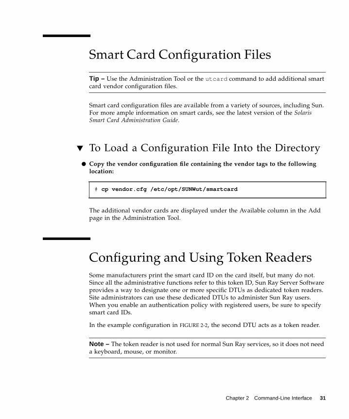
▼ To Edit a Single Desktop’s Properties 53
Managing Multihead Groups 54
▼ To View All Multihead Groups 54
Managing Sun Ray Device Services 56
▼ To Enable or Disable Sun Ray Device Services 56
Examining Log Files 58
▼ To View a Log File 59
Managing Smart Cards 60
▼ To View or List Configured Smart Cards 60
▼ To View The Smart Card Probe Order 63
▼ To Change the Smart Card Probe Order 63
▼ To Add a Smart Card 64
▼ To Delete a Smart Card 64
Sun Ray System Status 65
▼ To View the Sun Ray System Status 65
Administering Users 66
▼ To View Users by ID 67
▼ To View Users by Name 68
vi SRSS 3.1 Administrator’s Guide • September 2005

▼ To Delete a User 69
▼ To View Current Users 71
▼ To Display a User’s Current Properties 71
▼ To Add a User 72
▼ To View the User’s Sessions 73
▼ To Edit a User’s Properties 74
▼ To Add a Token ID to a User’s Properties 74
▼ To Delete a Token ID From a User’s Properties 75
▼ To Enable or Disable a User’s Token 75
▼ To Find a User 76
▼ To Get a Token ID From a Token Reader 77
Managing Sessions 78
▼ To Find Sun Ray Sessions 78
▼ To View Sun Ray Sessions 79
4. Peripherals for Sun Ray DTUs 81
Device Nodes and USB Peripherals 81
Device Nodes 82
Device Links 82
Device Node Ownership 83
Hotdesking and Device Node Ownership 83
Attached Printers 84
Printer Setup 84
▼ To Set Up a Printer 84
Printers Other Than PostScript Printers 85
Adapters 86
libusb 86
5. Hotdesking (Mobile Sessions) 87
Contents vii

Regional Hotdesking 87
Functional Overview 88
Site Requirements 88
Providing Site Integration Logic 89
▼ To Configure a Site-specific Mapping Library 89
Token Readers 90
▼ To Configure the Sample Data Store 90
▼ To Disable Regional Hotdesking 91
6. Encryption and Authentication 93
Introduction 93
Security Configuration 94
Security Mode 94
Session Security 95
Security Status 96
Session Connection Failures 97
7. Gnome Display Manager 99
Installation 99
Uninstallation 100
Configuration 100
Gnome Display Manager Privileges 100
8. Deployment on Shared Networks 103
Sun Ray DTU Initialization Requirements 103
DHCP Basics 104
DHCP Parameter Discovery 105
DHCP Relay Agent 106
Network Topology Options 106
Directly-Connected Dedicated Interconnect 108
viii SRSS 3.1 Administrator’s Guide • September 2005

Directly-Connected Shared Subnet 108
Remote Shared Subnet 108
Network Configuration Tasks 109
Preparing for Deployment 109
Deployment on a Directly-Connected Dedicated Interconnect 110
Directly-Connected Dedicated Interconnect: Example 111
Deployment on a Directly-Connected Shared Subnet 113
Directly-Connected Shared Subnet: Example 1 114
Directly-Connected Shared Subnet: Example 2 116
Deployment on a Remote Subnet 117
Remote Shared Subnet: Example 1 119
Remote Shared Subnet: Example 2 122
Network Performance Requirements 126
Packet Loss 126
Latency 126
Out-of-Order Packets 127
Troubleshooting Tools 127
utcapture 127
utquery 127
OSD Icons 127
Encapsulated Options 128
Remote Configuration 129
Enhancements to Firmware Download and Configuration Support 130
9. Multihead Administration 133
Multihead Groups 133
Multihead Screen Configuration 134
Multihead Screen Display 135
Multihead Administration Tool 136
Contents ix

▼ To Turn On Multihead Policy From the Command Line 136
▼ To Turn On Multihead Policy Using the Administration Tool 136
▼ To Create a New Multihead Group 137
XINERAMA 139
Session Groups 140
Authentication Manager 140
10. Failover Groups 143
Failover Group Overview 144
Setting Up IP Addressing 146
Setting Up Server and Client Addresses 146
Server Addresses 147
Configuring DHCP 148
Coexistence of the Sun Ray Server With Other DHCP Servers 148
Administering Other Clients 148
▼ To Set Up IP Addressing on Multiple Servers Each With One Sun RayInterface 149
Group Manager 151
Redirection 152
Group Manager Configuration 152
▼ To Restart the Authentication Manager 153
Load Balancing 153
▼ To Turn Off the Load Balancing Feature 153
Setting Up a Failover Group 154
Primary Server 154
▼ To Specify a Primary Server 154
Secondary Server 155
▼ To Specify Each Secondary Server 155
▼ To Add Additional Secondary Servers 155
x SRSS 3.1 Administrator’s Guide • September 2005

Removing Replication Configuration 155
▼ To Remove the Replication Configuration 155
Viewing the Administration Status 156
▼ To Show Current Administration Configuration 156
Viewing Failover Group Status 156
▼ To View Failover Group Status 156
Sun Ray Failover Group Status Icons 157
Recovery Issues and Procedures 158
Primary Server Recovery 158
▼ To Rebuild the Primary Server Administration Data Store 159
▼ To Replace the Primary Server with a Secondary Server 160
Secondary Server Recovery 160
Setting Up a Group Signature 161
▼ To Change the Group Manager Signature File 161
Taking Servers Offline 161
▼ To Take a Server Offline 162
▼ To Bring a Server Online 162
A. User Settings and Concerns 163
Supported Devices and Libraries 163
Sun Ray DTU Settings 163
▼ To Change the Sun Ray Settings 163
Monitor Settings 164
Hot Key Preferences 165
Hot Key Values 167
▼ To Change the Hot Key for the Settings GUI 167
▼ To Change the Hot Key Setting for a Single User 167
Power Cycling a Sun Ray DTU 168
▼ To Power Cycle a Sun Ray DTU 168
Contents xi

▼ To Perform a Soft Reset 168
▼ To Kill a User’s Session 168
B. Troubleshooting and Tuning Tips 169
Understanding OSD 169
OSD Icon Topography 169
Sun Ray Desktop Unit Startup 172
▼ Actions to take if this icon stays on for more than 10 seconds: 172
▼ Actions to take if this icon stays on for more than 10 seconds: 172
▼ Actions to take: 173
▼ Actions to take if the icon displays for more than a few seconds or ifthe DTU continues to reset after the icon is displayed: 174
▼ To Identify a Hung Session 174
▼ To Kill a Hung Session 174
Firmware Download 175
▼ Actions to take: 175
▼ Actions to take: 176
Firmware Download Failed 176
▼ Actions to take: 176
Bus Busy 176
No Ethernet 177
▼ Actions to take: 177
Ethernet Address 177
Session Connection Failures 178
▼ Actions to take: 178
Token Reader Icon 178
Card Read Error OSD 179
▼ Actions to take: 179
Prompt for Card Insertion OSD 179
xii SRSS 3.1 Administrator’s Guide • September 2005

Access Denied OSD 179
Wait for Session OSD 180
Wait Icon Cursor for Default Session Type 181
Patches 181
Authentication Manager Errors 181
Audio 184
Audio Device Emulation 184
Audio Malfunction 184
▼ To Activate the Redirection Library 185
Performance Tuning 185
General Configuration 185
Applications 186
Sluggish Performance 186
Monitor Display Resolution Defaults to 640 x 480 186
▼ To Correct or Reset the Screen Resolution: 187
Old Icons (Hourglass with Dashes Underneath) Appear on Display 187
Port Currently Owned by Another Application 187
Design Tips 188
Glossary 189
Index 199
Contents xiii

xiv SRSS 3.1 Administrator’s Guide • September 2005

Figures
FIGURE 1-1 Authentication and Session Manager Interaction 6
FIGURE 1-2 Sun Ray System with a Dedicated Interconnect Fabric 9
FIGURE 1-3 Example of Shared Physical Resources in Multiple VLANs Configuration 10
FIGURE 1-4 Small Deployment Scenario 12
FIGURE 1-5 Simple Failover Group 13
FIGURE 2-1 The Server Selection (utselect) GUI 20
FIGURE 2-2 Using a Token Reader to Register Smart Cards 32
FIGURE 3-1 Login Window 39
FIGURE 3-2 Summary Status Window 40
FIGURE 3-3 Change Admin Password Window 41
FIGURE 3-4 Change Policy WindowAlthough Non-Smart Card Sessions are not currently supported on Linux, an otherwisesimilar looking screen enables you to make other policy changes. 42
FIGURE 3-5 Sun Ray Services Window 43
FIGURE 3-6 View Current Desktops Window 45
FIGURE 3-7 Current Properties Window 46
FIGURE 3-8 Edit Desktop Properties Window 47
FIGURE 3-9 View Current Desktops Window Showing Token Readers 48
FIGURE 3-10 Current Properties of a Token Reader 49
FIGURE 3-11 View All Desktops Window 50
FIGURE 3-12 View Current Users Window 51
xv

FIGURE 3-13 Find Desktop Window 52
FIGURE 3-14 Find Desktop Search Results Window 53
FIGURE 3-15 The Multihead Groups Window 54
FIGURE 3-16 The Multihead Group Properties Window 55
FIGURE 3-17 Desktops Current Properties Window 56
FIGURE 3-18 Device Services Window 57
FIGURE 3-19 Administration Log File WindowAlthough this figure shows a log not currently available on Linux, other logs are displayed ina similar fashion. 59
FIGURE 3-20 The View Configured Smart Cards Window 61
FIGURE 3-21 Smart Card Properties Window 62
FIGURE 3-22 Smart Card Probe Order Window 63
FIGURE 3-23 Add Smart Card to Probe List Window 64
FIGURE 3-24 Summary Status Window 65
FIGURE 3-25 View Users by ID Window 67
FIGURE 3-26 View Users by Name Window 68
FIGURE 3-27 The Current Properties Window Shows Administrative Options for a User 69
FIGURE 3-28 Delete User Window 70
FIGURE 3-29 View Current Users Window 71
FIGURE 3-30 Add User Window 72
FIGURE 3-31 Edit User Properties Page 74
FIGURE 3-32 Find User Window 76
FIGURE 3-33 Get Token ID Window 77
FIGURE 3-34 Sessions on Current Sun Ray Server Window 79
FIGURE 6-1 Sun Ray Security Configuration Window 95
FIGURE 8-1 Network Topologies for Sun Ray DTU Deployment 107
FIGURE 8-2 Sun Ray Network Topology 110
FIGURE 9-1 The Multihead Screen Display 136
FIGURE 9-2 Multihead Group List With Group Detail 137
FIGURE 9-3 Create New Multiheaded Group Pop-up Dialog Box 137
FIGURE 9-4 Setup Display for the New Multihead Group 138
xvi SRSS 3.1 Administrator’s Guide • September 2005

FIGURE 9-5 Completed Multihead Group List With Active Finish Button 138
FIGURE 9-6 Authentication Manager Flowchart for the Primary DTU 140
FIGURE 9-7 Authentication Manager Flowchart for the Secondary DTU 141
FIGURE 10-1 Simple Failover Group 144
FIGURE 10-2 Redundant Failover Group 145
FIGURE 10-3 Failover Group Status Table 157
FIGURE A-1 Settings Screen 164
FIGURE B-1 Ethernet Address OSD with Different Encryption and Authentication States 177
Figures xvii

xviii SRSS 3.1 Administrator’s Guide • September 2005

Tables
TABLE 2-1 Supported Commands 16
TABLE 2-2 utrestart Commands 22
TABLE 2-3 Data Elements Displayed 33
TABLE 2-4 utcapture Options 34
TABLE 3-1 Log Files 58
TABLE 3-2 Key User Fields 66
TABLE 3-3 Login Status Fields 72
TABLE 3-4 Sun Ray Session States 78
TABLE 4-1 Definitions of Naming Conventions 82
TABLE 8-1 DHCP Service Parameters Available 105
TABLE 8-2 Vendor-specific DHCP Options 124
TABLE 10-1 Configuring Five Servers for 100 DTUs 146
TABLE 10-2 Available Options 151
TABLE 10-3 Failover Group Status Icons 157
TABLE A-1 Sun Ray Settings Properties Files 166
TABLE A-2 Specific Hot Key Values 166
TABLE B-1 Icon Messages 170
TABLE B-2 DCHP State Codes 171
TABLE B-3 Power LED 171
TABLE B-4 Error Message Examples 183
xix

xx SRSS 3.1 Administrator’s Guide • September 2005

CHAPTER
Preface
The Sun Ray Server Software 3.1 Administrator’s Guide for the Linux Operating Systemprovides instructions for setting up, administering, monitoring, and troubleshootinga system of Sun Ray ™ Desktop Units (DTUs) and their server or servers. It iswritten for system administrators who are already familiar with the Sun Ray ™computing paradigm and have substantial networking knowledge. This guide mayalso be useful for those interested in customizing Sun Ray systems.
Before You Read This BookThis guide assumes that you have installed the Sun Ray Server Software on yourserver from the Sun Ray Server Software 3.1 CD or the Electronic SoftwareDownload (ESD) and that you have added the required patches.
How This Book Is OrganizedChapter 1 gives an overview of the Sun Ray system.
Chapter 2 describes the command-line interface.
Chapter 3 describes the Administration Tool.
Chapter 4 describes peripheral devices for Sun Ray DTUs.
Chapter 6 gives a brief description of traffic encryption between Sun Ray clients andservers and server-to-client authentication.
i

Chapter 7 provides details on installation and configuration of the Gnome DisplayManager.
Chapter 8 discusses network requirements, including LAN, VLAN, and dedicatedinterconnect options, switch requirements, and other network topology issues.
Chapter 9 describes how to implement multihead and XINERAMA features on a SunRay system.
Chapter 10 discusses failover groups.
Appendix A addresses user issues and concerns.
Appendix B provides troubleshooting information, including error messages fromthe Authentication Manager.
This manual also contains a glossary and an index.
Using UNIX CommandsThis document does not contain information on basic UNIX® commands andprocedures, such as shutting down the system, booting the system, or configuringdevices. This document does, however, contain information about specific Sun Raysystem commands.
ii Sun Ray Server Software 3.1 Administrator’s Guide • September 2005

Typographic Conventions
Shell Prompts
Typeface Meaning Examples
AaBbCc123 The names of commands, files,and directories; on-screencomputer output
Edit your.login file.Use ls -a to list all files.% You have mail.
AaBbCc123 What you type, whencontrasted with on-screencomputer output
% su
Password:
AaBbCc123 Book titles, new words or terms,words to be emphasized
Read Chapter 6 in the User’s Guide.These are called class options.You must be superuser to do this.
Command-line variable; replacewith a real name or value
To delete a file, type rm filename.
Shell Prompt
C shell machine_name%
C shell superuser machine_name#
Bourne shell and Korn shell $
Bourne shell and Korn shell superuser #
Chapter Preface iii

Related Documentation
Accessing Sun DocumentationYou can view, print, or purchase a broad selection of Sun documentation, includinglocalized versions, at:
http://www.sun.com/documentation
Sun Welcomes Your CommentsSun is interested in improving its documentation and welcomes your comments andsuggestions. You can email your comments to Sun at:
Please include the part number (819-2389-10) of your document in the subject line ofyour email.
Application Title Part Number
Installation Sun Ray Server Software 3.1 Installationand Configuration Guide for the LinuxOperating System
817-6810-10
Release Notes Sun Ray Server Software 3.1 Release Notesfor the Linux Operating System
817-6813-10
iv Sun Ray Server Software 3.1 Administrator’s Guide • September 2005

CHAPTER 1
Sun Ray System Overview
Although thin client computing has been discussed and attempted for many years,Sun Ray is the first implementation to offer both workstation-like user functionalityand sufficient speed and reliability to be suitable for mission-critical applications.The latest generation of Sun Ray Server Software now supports many USBperipheral devices, LAN and low-bandwidth WAN deployment. Originallydeveloped on Sun’s Solaris™ Operating System, Sun Ray Server Software is nowalso supported on three Linux variants: Red Hat Enterprise Linux Advanced Server3, SuSE Linux Enterprise Server 8, and Sun Java™ Desktop System 2.
Computing ModelThe Sun Ray system employs a network-dependent model in which all computing isperformed on a server, with input and output data passed back and forth betweenthe Sun Ray server and the Sun Ray Desktop Units (DTUs). Nearly any Sun serverwith sufficient capacity can be configured as a Sun Ray server so long as it runs asupported version of the Solaris operating system or one of the supported flavors ofLinux.
Various models of Sun Ray DTU are available, differing primarily with respect tosize and type of screen; however, all Sun Ray DTUs also include a smart card reader,a keyboard, and a mouse. Sun Ray DTUs have no local disks, operating systems, orapplications; they are therefore considered stateless. This is what makes them true, or“ultra” thin clients, and it is what makes them inexpensive to maintain as well asextremely secure, both from an intellectual property perspective and for governmentwork. Although USB devices are supported, the ability to use them is administeredcentrally so that sites with security requirements can easily remove the sort of riskimposed by PCs and other fat clients that allow the theft of data in case a physicaldevice is stolen.
1

Because effective client-server network traffic often relies on the rapid movement oflarge numbers of packets, an optimal Sun Ray implementation requires a well-designed network. Most large implementations include at least one failover group toensure uninterrupted service whenever a server goes off-line.
Once a failover group is set up, Sun Ray Server Software provides automatic loadbalancing to optimize performance by spreading the computing load among theservers in the group. If a server is taken out of service, the Group Manager on eachremaining server tries to distribute that server’s sessions evenly among theremaining servers. The load balancing algorithm takes into account each server’sload and capacity (number and speed of its CPUs) so that larger or less heavilyloaded servers host more sessions. These concepts are addressed in Chapter 10 andin the Sun Ray Server Software 3.1 Installation and Configuration Guide.
User sessions—groups of services controlled by the Session Manager and associatedwith a user through an authentication token—reside on a server and are directed toa Sun Ray DTU. Because Sun Ray DTUs are stateless, a user session can beredirected to any Sun Ray DTU on the appropriate network or subnetwork when auser logs in or inserts a smart card.
While the session continues to reside on a server, it appears to follow the user to thenew DTU. This functionality, called session mobility, is the key architectural featurethat enables hotdesking—the ability of users to access their sessions from any DTU ontheir network. In early versions of Sun Ray Server Software, mobile sessions werepossible only with smart cards. It is now possible to enable hotdesking with orwithout smart cards. In addition, regional hotdesking now lets users access theirsessions from increasingly remote locations.
The Sun Ray SystemThe Sun Ray system consists of Sun Ray DTUs, servers, server software, and thephysical networks that connect them.
Sun Ray DTUThe Sun Ray desktop unit (DTU) delivers and may exceed the full functionality of aworkstation or a multimedia PC. The key features include:
■ 24-bit, 2-D accelerated graphics up to 1920 x 1200 resolution at 72 Hz (640 x 480 at60 Hz is the lowest resolution)
■ Multichannel audio input and output capabilities■ Smart card reader■ USB ports that support hot-pluggable peripherals
2 Sun Ray Server Software 3.1 Administrator’s Guide • September 2005

■ Serial port (for the Sun Ray 170 and later models)■ EnergyStar™ compliance
■ No fan, switch, or disk■ Very low power consumption
The DTU acts as a frame buffer on the client side of the network. Applications runon the server and render their output to a virtual frame buffer. Sun Ray serversoftware formats and sends the rendered output to the appropriate DTU, where theoutput is interpreted and displayed.
From the point of view of network servers, Sun Ray DTUs are identical except fortheir Ethernet MAC addresses. If a DTU ever fails, it can easily be replaced.
IP addresses are leased to each Sun Ray DTU when it is connected and can be reusedwhen the DTU is disconnected. IP address leasing is managed by the Dynamic HostConfiguration Protocol (DHCP). In cases where they already exist on a network thatwill support Sun Ray DTUs, separate DHCP servers may be useful for tasks such asassigning IP addresses and network parameters to the DTUs. The use of separateDHCP servers is not required; however, because they require static IP addresses, SunRay Servers cannot be DHCP clients. These questions are discussed in Chapter 8 andAppendix B.
Multihead Displays
Sun Ray Server Software supports the use of multiple displays connected to a singlekeyboard and pointer. This functionality is important for users who need extrascreen real estate, for instance, to monitor many applications or systemssimultaneously or to accommodate a single application, such as a large spreadsheet,across multiple screens. To use multiple screens, the administrator sets up multiheadgroups, consisting of two or more DTUs, for those users who need them.Administration of multihead groups is explained in Chapter 9.
Firmware Module
A small firmware module in each Sun Ray DTU can be updated from the server. Thefirmware module checks the hardware with a power–on self test (POST) andinitializes the DTU. The DTU contacts the server to authenticate the user, and it alsohandles low-level input and output, such as keyboard, mouse, and displayinformation. If there is a problem with the DTU, the module displays an on–screendisplay (OSD) icon to make it easier to diagnose. OSD icons are described inAppendix B.
Chapter 1 Sun Ray System Overview 3

Sun Ray Server SoftwareSun Ray server software allows the administrator to configure network connections,select an authentication protocol, administer users, define desktop properties,monitor the system, and troubleshoot a wide variety of administration problems.
Sun Ray server software includes:
■ User authentication and access control■ Encryption between the Sun Ray server and DTUs■ System administration tools■ Session management■ Device management, including application-level USB access■ Virtual device drivers for audio and serial, parallel, and mass storage USB devices
Sun Ray server software enables direct access to all Linux X11 applications. Third-party applications running on the Sun Ray server can provide access to MicrosoftWindows NT applications and a variety of legacy (mainframe) applications.
Authentication Manager
The Authentication Manager implements the chosen policies for identifying andauthenticating users on Sun Ray DTUs. The Authentication Manager uses pluggablecomponents called modules to implement various site-selectable authenticationpolicies.
The Authentication Manager also verifies user identities and implements site accesspolicies. It can also be used to supply an audit trail of the actions of users who havebeen granted administrative privileges over Sun Ray services. The AuthenticationManager is not visible to the user.
The interaction between the Authentication Manager and the DTU works as follows:
1. A user accesses a DTU.
2. The DTU sends the user’s token information to the Authentication Manager andrequests access. If a smart card is presented to the DTU, the smart card’s type andID are the token. If not, the DTU’s Ethernet address is sent.
3. If the Authentication Manager runs through the entire list of modules and nomodule takes responsibility for the request, the user is denied.
4. If the user is accepted, the Authentication Manager starts an X Windows sessionfor the user, which takes the user to the login screen. Solaris implementations usethe dtlogin screen; Linux implementations use GDM.
Normally, the Sun Ray DTU looks for the AuthSrvr DHCP option and contacts thataddress. If that field has not been supplied, or if the server does not respond, theDTU sends a broadcast request for any authentication manager on its subnet.
4 Sun Ray Server Software 3.1 Administrator’s Guide • September 2005

As an alternative, the administrator can supply a list of servers. If the authenticationlist is specified, only addresses on the list are checked. The Authentication Manageraddresses are tried in order until a connection is made.
The site administrator can construct a combination of the different modules andtheir options to implement a policy tailored to the site’s needs.
The modules are:
■ StartSession
Any type of token is accepted. Users are automatically passed through to thelogin window. This module is designed primarily for implementations in whichSun Ray DTUs replace workstations or PCs.
■ Registered
The token is accepted only if the token has been registered in the Sun Rayadministration database and the token is enabled. If the token does not meet theseconditions, it is rejected. If accepted, the user is passed through to the loginwindow. This module is designed for sites that want to restrict access to onlycertain users or DTUs.
Users can be registered in two ways, reflecting two possible policy decisions forthe administrator:
■ Central Registration
The administrator assigns smart cards and/or DTUs to authorized users andregisters users’ tokens in the Sun Ray administration database.
■ Self-Registration
Users register themselves in the Sun Ray administration database. If this modeis enabled and the Authentication Manager is presented with an unregisteredtoken, the user is prompted with a registration window. In this case, the userprovides the same information a site administrator would request.
If self-registration is enabled, users can still be registered centrally. If a token hasbeen registered but disabled, the user cannot re-register the token; the user mustcontact the site administrator to re-enable the token.
Chapter 1 Sun Ray System Overview 5

FIGURE 1-1 Authentication and Session Manager Interaction
Sessions and Services
A session consists of a group of services controlled by the Session Manager.
The session is associated with a user through an authentication token. A service isany application that can connect directly to the Sun Ray DTU. This can includeaudio, video, X servers, and device control of the DTU. For example, dtmail is nota service because it is accessed through an X server.
Session Manager
The Session Manager interacts with the Authentication Manager and directs servicesto the user. The Session Manager is used at start up for services, for managing screenreal estate, and as a rendezvous point for the Authentication Manager.
The Session Manager keeps track of sessions and services by mapping services tosessions and binding and unbinding related services to or from a specific DTU. TheSession Manager takes authentication only from authorized AuthenticationManagers listed in the /etc/opt/SUNWut/auth.permit file.
The steps below describe how the process starts and ends:
1. After a user’s token is authenticated, the Authentication Manager determineswhether a session exists for that token. If a session does not exist, theAuthentication Manager asks the Session Manager to create a session and then
AuthenticationManager
SessionManager
Smart Card
Module 1
Module 2
Module 3
User’sDesktop
Session 1
Session 2Sun RayDTU
Session 3
6 Sun Ray Server Software 3.1 Administrator’s Guide • September 2005

starts the appropriate service(s) for the session according to the policy decisionstaken by the administrator. Creating a session usually involves starting anXserver process for the session.
2. When services are started, they explicitly join the session by contacting theSession Manager.
3. The Authentication Manager informs the Session Manager that the sessionassociated with the token is to be connected to a specific Sun Ray DTU. TheSession Manager then informs each service in the session that it should connectdirectly to the DTU.
4. The Authentication Manager determines that the session associated with a tokenshould be disconnected from a DTU. The Authentication Manager notifies theSession Manager which, in turn, notifies all the services in the session todisconnect.
5. The Session Manager mediates control of the screen real estate betweencompeting services in a session and notifies the services of changes in screen realestate allocation.
Caution – It is important to keep the session ID private. If the user’s session ID isrevealed, unauthorized applications can connect directly to the DTU. Thexprop(1) command can reveal an end user’s secret session ID. Also, careless use ofthe xhost(1) command (for example, typing xhost +) can allow an intruder touse xprop to capture a user’s session ID. This action can expose the user’s screenimages and keyboard input to anyone interested.
Tip – Use xhost username@system to enable only those people you specify toaccess the display and the user’s DTU.
The Session Manager is consulted only if the state of the session changes or if otherservices are added. When a user’s token is no longer mapped to a DTU (for example,when a card is removed), the Session Manager disconnects the services from theDTU, but the services remain active on the server. For example, programs attachedto the X server continue to run although their output is not visible. The SessionManager daemon must continue running all the time.
Note – To verify that the Session Manager daemon is running, use the ps commandand look for utsessiond.
Chapter 1 Sun Ray System Overview 7

If the Authentication Manager quits, the Session Manager disconnects all thesessions it authorized and tells them that they have to be re-authenticated. Theservices are disconnected but still active. If the Session Manager is disrupted, itrestarts automatically. Each service contacts the Session Manager to requestreattachment to a particular session.
CLI and Admin GUI
Sun Ray Server Software has both a command-line interface (CLI) and a graphicaluser interface for administrative functions. The CLI is the recommended interface forenabling assistive technologies; the Sun Ray Administration Tool (Admin GUI) isprovided for convenience.
Data Store
Sun Ray Server Software 3.1 provides a private data store service, the Sun Ray DataStore (SRDS). The SRDS provides group-wide access to SRSS administration data.
Network ComponentsIn addition to the servers, server software, DTUs, smart cards, and peripheraldevices, such as local printers, the Sun Ray system needs a well-designed network,configured in one of several possible ways, including:
■ Dedicated interconnect■ VLAN (Virtual Local Area Network)■ LAN (Local Area Network), with or without network routers■ Low-bandwidth1 WAN (Wide Area Network)
Various types of network configuration are discussed in depth in Chapter 8.
Sun Ray Interconnect Fabric
Early Sun Ray implementations relied on dedicated interconnects, using physicallydedicated Ethernet networks or logically dedicated networks. Sun Rays can now bedeployed on existing Local Area Network (LAN) infrastructure, eliminating therequirement for a dedicated interconnect.
1. Bandwidth less than 2 Mbps.
8 Sun Ray Server Software 3.1 Administrator’s Guide • September 2005

FIGURE 1-2 Sun Ray System with a Dedicated Interconnect Fabric
The Sun Ray interconnect fabric is based on 10/100BASE-T Ethernet technology,using layer-2 or layer-3 switches and Category 5 wiring. Each Sun Ray DTU isattached to the interconnect fabric through its built-in 10/100BASE-T interface.
The following sections illustrate some conservative methods of providing gooddesktop performance to Sun Ray users at a low cost. Many other network scenariosare possible.
VLAN Implementation
VLANs logically partition a single physical interconnect into two or more broadcastdomains. VLANs are commonly configured to implement virtual subnets in a sharedphysical interconnect. However, because VLANs must share backplane and linkbandwidth, they are not true dedicated interconnects.
Implementing a Sun Ray interconnect through VLANs creates a logically dedicatedconnection, but can also mean sharing physical resources with uncontrolled, non-Sun Ray traffic. These resources could be the limited backplane bandwidth within aswitch or on a link that carries multiple VLANs between switches (see FIGURE 1-3). Ifthese resources are consumed by other devices, significant amounts of Sun Ray DTUtraffic might be dropped and the results seen as horizontal bands or blocks on theuser’s display.
Sun Ray DTUsLAN
Sun Ray Server
Ethernet Switch
Interconnect Fabric
Chapter 1 Sun Ray System Overview 9

FIGURE 1-3 Example of Shared Physical Resources in Multiple VLANs Configuration
Since switch manufacturers configure their products differently, please refer to thedocumentation provided with your switch and refer all questions relating to settingup or configuring VLANs to your switch manufacturer.
Implementing the interconnect with a physically dedicated and isolated set ofEthernet switches was recommended because it is easy and reliable. For instance:
■ Only layer 2 switches are required.■ The only switch configuration required is to enable fast boot times.■ No ongoing switch configuration and management is required.■ Issues of bandwidth and poor topology are greatly reduced.
LAN Implementation
With Sun Rays deployed on a LAN, users can exercise session mobility across amuch larger “domain”—a huge convenience. For basic instructions on configuringdifferent types of networks for Sun Ray implementation, see “Basic Network
VLAN 1
VLAN 2
VLAN 1VLAN 2
Sun RayServer
VLAN 1
VLAN 1
Sun Ray DTUs
VLANs1 & 2
Shared Resources
10 Sun Ray Server Software 3.1 Administrator’s Guide • September 2005

Topology” on page 32 of the Sun Ray Server Software 3.1 Installation and ConfigurationGuide. For a more detailed discussion of network taxonomy and configuration, see“Deployment on Shared Networks” on page 103.
Physical ConnectionsThe physical connection between the Sun Ray server and Sun Ray clients relies onstandard switched Ethernet technology.
To boost the power of the interconnect and shield Sun Ray DTU users from thenetwork interaction taking place at every display update, 100 Mbps switches arepreferred.
There are two basic types of 100 Mbps switches:
■ Low-capacity switches—These switches have 10/100 Mbps interfaces for eachport.
■ High-capacity switches—These switches have 10/100 Mbps interfaces for eachterminal port, but one or more gigabit interfaces to attach to the server.
Either type of switch can be used in the interconnect. They can be managed orunmanaged; however, some managed switches may require basic configuration to beused on a Sun Ray network.
Server-to-switch bandwidth should be scaled based on end-user multiplexing needsso that the server-to-switch link does not become overly saturated. Gigabit uplinkports on the switch provide high-bandwidth connections from the server, thusincreasing the number of supportable clients. The distance between the server andthe switch can also be extended using gigabit fiber-optic cabling.
The interconnect may be completely dedicated and private, or a VLAN, or it may bepart of the corporate LAN. For private interconnects, the Sun Ray server uses at leasttwo network interfaces: one for the corporate LAN, the other for the Sun Rayinterconnect.
Even in a LAN deployment, two server network interfaces are recommended: one toconnect to the general LAN and one to connect the server to back-end services, suchas file servers, compute grids, and large databases.
Deployment ExamplesThere is no physical or logical limit to the ways that a Sun Ray system can beconfigured. The following sections offer some typical examples.
Chapter 1 Sun Ray System Overview 11

Small Deployments
For smaller deployments, such as those with between five and 50 Sun Ray DTUs, theSun Ray server uses a single 100BASE-T card to connect to a 100BASE-T switch. Thisswitch, in turn, connects to the Sun Ray DTUs. With five or fewer DTUs, a wirelessinterconnect works acceptably at 10 Mbytes.
For example, in FIGURE 1-2 a Sun Enterprise™ server with a Sun 10/100BASE-T cardand a 24-port 10/100BASE-T switch can easily support 23 users performing standarddesktop activities.
Medium to Large Deployments
For larger departments with groups consisting of hundreds or thousands of Sun RayDTUs, the Sun Ray server uses a gigabit Ethernet card to connect to large10/100BASE-T switches. Especially with the low-bandwidth enhancements to SRSS,there is no performance need to have more than one gigabit link from the server tothe Sun Ray DTU’s network.
A 100-user departmental system, for example, consisting of a Sun Enterprise server,one gigabit Ethernet card, and two large (48-port and 80-port) 10/100BASE-Tswitches delivers services to the 100 Sun Ray DTUs (see FIGURE 1-4).
FIGURE 1-4 Small Deployment Scenario
Sun
Gigabit
80-port, 10/100BASE-T switch
Sun Ray DTUs Sun Ray DTUs
LAN
EnterpriseServer
with gigabit uplink and downlink ports48-PORT 10/100BASE-Tswitch with gigabit uplink
EthernetCard
12 Sun Ray Server Software 3.1 Administrator’s Guide • September 2005

Failover Group Scenario
Sun Ray servers can be bound together to create failover groups. A failover group,comprising two or more servers, provides users with a higher level of availability incase one servers become unavailable due to a network or system failure.
When a server in a failover group goes down, whether for maintenance, a poweroutage, or any other reason, each Sun Ray DTU connected to it reconnects to anotherserver in the failover group. The DTU connects to a previously existing session forthe current token, if there is one, on another server; if there is no existing session, theDTU connects to a server selected by the load balancing algorithm. This serverpresents a login screen to the user, who must log in again to create a new session.The session on the failed server is lost. Failover groups are discussed in Chapter 10as well as in the Sun Ray Server Software 3.1 Installation and Configuration Guide.
Regional Hotdesking
In addition, enterprises with multiple failover groups and users who move from onelocation to another — such as between corporate headquarters and various branchoffices — may wish to configure regional hotdesking. This feature allows users toaccess their sessions across a wider domain and longer distance than simply usingdifferent DTUs within a single failover group.
FIGURE 1-5 Simple Failover Group
Sun Ray DTUs
Public
Sun Ray Servers
Interconnect
SwitchesNetwork
Chapter 1 Sun Ray System Overview 13

Security ConsiderationsUsing switched network gear for the last link to the DTUs makes it hard for amalicious PC user or network snooper at one of the network ports to obtainunauthorized information. Because switches send packets only to the proper outputport, a snooper plugged into another port receives no unauthorized data. If theserver and wiring closet are secure, the last step is switched, and the DTU is pluggeddirectly into the wall jack, then it is very difficult to intercept communicationsbetween the server and the DTU. SRSS encryption features also help to protectsensitive data by providing the options to encode keyboard input and display traffic.
14 Sun Ray Server Software 3.1 Administrator’s Guide • September 2005

CHAPTER 2
Command-Line Interface
The Command-Line Interface (CLI) is the recommended interface for enablingassistive technologies.
This chapter contains the following information:
■ “Supported Commands” on page 15■ “Session Redirection” on page 19■ “Changing Policies” on page 21■ “Enabling Multiple Administration Accounts” on page 22■ “Enabling and Disabling Device Services” on page 24■ “Configuring Interfaces on the Sun Ray Interconnect Fabric” on page 26■ “Managing Firmware Versions” on page 29■ “Restarting the Sun Ray Data Store (SRDS)” on page 30■ “Smart Card Configuration Files” on page 31■ “Using the utcapture Tool” on page 33
Supported CommandsCommands that can be executed from the command line are listed in TABLE 2-1, anda few of the most important commands are documented in this chapter. For furtherinformation on executing these commands, see the man page for the command inquestion.
15

To view any of the specific commands for the Sun Ray system, type:
or type:
% man -M /opt/SUNWut/man command
% setenv MANPATH=/opt/SUNWut/man% man command
TABLE 2-1 Supported Commands
Command Definition
utaction The utaction program provides a way to execute commands when a Sun RayDTU session is connected or disconnected.
utadm The utadm command manages the private network, shared network, and DHCP(Dynamic Host Configuration Protocol) configuration for the Sun Rayinterconnect.
utadminuser The utadminuser command is used to add, list, and delete UNIX usernames fromthe list of users authorized to administer Sun Ray services. The list is stored in theSun Ray data store.
utamghadm The utamghadm command is used to configure or disable regional hotdesking,which allows users to access their sessions across multiple failover groups.
utcapture The utcapture command connects to the Authentication Manager and monitorspackets sent and packets dropped between the Sun Ray server and the Sun RayDTUs.
utcard The utcard command allows configuration of different types of smart cards inthe Sun Ray administration database
utconfig The utconfig command performs the initial configuration of the Sun Ray serverand supporting administration framework software.
utcrypto The utcrypto command is a utility for security configuration.
utdesktop The utdesktop command allows the user to manage Sun Ray DTUs connected tothe Sun Ray server that the command is run on.
utdetach The utdetach command disconnects the current non-smart card mobile sessionor authenticated smart card session from its respective Sun Ray DTU. The sessionis not destroyed but put into a detached state. The session can be accessed if thesame user token (user name) is presented to the Sun Ray server.
16 Sun Ray Server Software 3.1 Administrator’s Guide • September 2005

utdevadm The utdevadm command is used to enable/disable Sun Ray device services. Thisincludes USB devices connected through USB ports, embedded serial ports, andinternal smartcard reader in the Sun Ray DTU.
utdssync The utdssync command converts the port number for the Sun Ray Data Storeservice to the new default port on servers in a failover group, then forces allservers in the group to restart Sun Ray services.
utfwadm The utfwadm command manages firmware versions on the Sun Ray DTUs.
utfwload The utfwload command is used primarily to force the download of newfirmware to a DTU running older firmware than its server.
utfwsync The utfwsync command refreshes the firmware level on the Sun Ray DTUs towhat is available on the Sun Ray servers in a failover group. It then forces all theSun Ray DTUs within the group to restart.
utgroupsig The utgroupsig command sets the failover group signature for a group of SunRay servers. The utgroupsig command also sets the Sun Data Store rootpwused by Sun Ray to a value based on the group signature. Although utgroupsigsets the rootpw in the utdsd.conf file, it does not set the admin password,which is a separate entity, in the Admin database.
utgstatus The utgstatus command allows the user to view the failover status informationfor the local server or for the named server. The information that the commanddisplays is specific to that server at the time the command is run.
utinstall The utinstall utility installs, upgrades, and removes Sun Ray Server Software.All software required to support the Sun Ray server is installed, including theadministration framework, and any patches required by the framework.
utmhadm The utmhadm command provides a way to administer Sun Ray server multiheadterminal groups. The information that utmhadm displays and that is editable isstored in the Sun Ray administration database.
utmhconfig The utmhconfig tool allows an administrator to list, add, or delete multiheadedgroups easily.
utpolicy The utpolicy command sets and reports the policy configuration of the Sun RayAuthentication Manager, utauthd(1M). This command’s -i and -t optionswere deprecated as of the 2.0 release. Please continue to use the utpolicycommand for policy changes, but use the utrestart command instead ofutpolicy -i, and use utreader instead of utpolicy -t.
utpreserve The utpreserve command saves existing Sun Ray Server Software configurationdata to the /var/tmp/SUNWut.upgrade directory.
utpw The utpw command changes the Sun Ray administrator password (also known asthe UT admin password) used by the Web-based and command-lineadministration applications.
TABLE 2-1 Supported Commands (Continued)
Command Definition
Chapter 2 Command-Line Interface 17

utquery The utquery command collects DHCP information from the Sun Ray DTUs.
utreader The utreader command is used to add, remove, and configure token readers.
utreplica The utreplica command configures the Sun Ray Data Store server to enablereplication of administered data from a designated primary server to eachsecondary server in a failover group. The data stores of the secondary serversremain synchronized automatically unless there is a power outage. The -z optionis useful for updating the port number.
utresadm The utresadm command allows an administrator to control the resolution andrefresh rate of the video monitor signal (persistent monitor settings) produced bythe Sun Ray unit.
utresdef The utresdef command lists the monitor resolutions and refresh rates that canbe applied to Sun Ray units through the utresadm command.
utrestart The utrestart command is used to start Sun Ray services.
utselect The utselect command presents the output of utswitch -l in a window andallows mouse-based selection of a Sun Ray server to which the Sun Ray DTU inuse is reconnected.
utsession The utsession command lists and manages Sun Ray sessions on the local SunRay server.
utset Use utset to view and change Sun Ray DTU settings.
utsettings The utsettings command opens a Sun Ray Settings dialog box that allows theuser to view or change audio, visual, and tactile settings for the Sun Ray DTU.
utswitch The utswitch command allows switching a Sun Ray DTU among Sun Rayservers in a failover group. It can also list the existing sessions for the currenttoken.
utuser The utuser command allows the administrator to manage Sun Ray usersregistered on the Sun Ray server that this command is run on. It also providesinformation on the currently inserted token (smart card) for a specified DTU thatis configured as a token reader.
utwall The utwall utility sends a message or an audio file to users having an Xnewt (Xserver unique to Sun Ray) process. The messages can be sent in email anddisplayed in a pop-up window.
utwho The utwho script assembles information about display number, token, logged-inuser, etc., in a compact format.
utxconfig The utxconfig program provides X server configuration parameters for users ofSun Ray DTU sessions.
TABLE 2-1 Supported Commands (Continued)
Command Definition
18 Sun Ray Server Software 3.1 Administrator’s Guide • September 2005

▼ To Stop Sun Ray Services
● Type:
▼ To Start Sun Ray Services
● Type:
This procedure starts Sun Ray services without clearing existing sessions.
Or
● Type:
This procedure starts Sun Ray services and clears existing sessions.
Session RedirectionIn addition to automatic redirection after a user’s token has been authenticated,whether via smart card token or direct login, the utselect graphical user interface(GUI) or the utswitch command can be used to redirect the session to a differentserver.
▼ To Redirect to a Different Server● From a shell window on the DTU, type:
# /etc/init.d/utsvc stop
# /opt/SUNWut/sbin/utrestart
# /opt/SUNWut/sbin/utrestart -c
% /opt/SUNWut/bin/utselect
Chapter 2 Command-Line Interface 19

The selections in the window are sorted in order of the most current to least currentactive sessions for the token ID.
In FIGURE 2-1, the Server column lists the servers accessible from the DTU. TheSession column reports the DISPLAY variable X session number on the server if oneexists. In the Status column, Up indicates that the server is available. The first serverin the list is highlighted by default. Select a server from the list or enter the name ofa server in the Enter server: field. If a server without an existing session is selected,a new session is created on that server.
FIGURE 2-1 The Server Selection (utselect) GUI
The OK button commits the selection of the highlighted or manually entered server.The Cancel button dismisses the GUI without making any changes to the session.The Refresh button reloads the window with the most current information.
Note – If only one server in the failover group is up, it is displayed in the utselectGUI. However, if selectAtLogin is set to true in the/etc/opt/SUNWut/auth.props file, the GUI is not displayed because thereappears to be only one server in the failover group.
20 Sun Ray Server Software 3.1 Administrator’s Guide • September 2005

▼ To Redirect a DTU Manually● From a shell window on the DTU, type:
where host is the host name or IP address of the Sun Ray server to which the selectedDTU is redirected, and token is the user’s token ID.
▼ To List Available Hosts● From a shell window, type:
Hosts available from the Sun Ray DTU are listed.
▼ To Select a Server with the Latest Session● In a shell window, type:
The DTU is redirected to the server with the latest session connect time.
Changing PoliciesWhen a policy is set with utpolicy, the group policy is set automatically, so all thatis needed at that point is to reset or restart services.
% /opt/SUNWut/bin/utswitch -h host [ -k token]
% /opt/SUNWut/bin/utswitch -l
% /opt/SUNWut/bin/utswitch -t
Chapter 2 Command-Line Interface 21

.
Enabling Multiple AdministrationAccountsIn previous releases, the Sun Ray Admin GUI supported authentication for only oneuser account, called admin, against the Sun Ray Data Store. Beginning with SRSS3.1, the Sun Ray Admin GUI allows UNIX usernames other than admin to administerSun Ray services, and it provides an audit trail of their activity. Any valid UNIX userin the authorized user list can now administer Sun Ray services. Seeutadminuser(1M).
Sun Ray Admin GUI authentication is now based on the PAM authenticationframework.
PAM EntriesIn order to support the old Data Store authentication, a new PAM module,/opt/SUNWut/lib/pam_sunray_admingui.so.1, is included in the Sun Rayproduct.
utconfig(1M) adds the following new PAM entry for Sun Ray Admin GUIconfiguration:
■ On Linux (/etc/pam.d/utadmingui):
TABLE 2-2 utrestart Commands
Command/Option Result
/opt/SUNWut/sbin/utrestart Use this option if a minor policy changewas made, such as adding a dedicatedtoken reader. With such minor changes, itis not necessary to terminate existingsessions.
/opt/SUNWut/sbin/utrestart -c Use this option if a significant policychange has been made, such as enablingor disabling access to mass storagedevices. All existing sessions areterminated.
auth sufficient /opt/SUNWut/lib/pam_sunray_admingui.so.1
22 Sun Ray Server Software 3.1 Administrator’s Guide • September 2005

▼ To Configure UNIX UsersTo configure the Sun Ray Admin GUI to use UNIX usernames instead of the defaultadmin account:
● Copy the auth entries from /etc/pam.d/login file into/etc/pam.d/utadmingui:
■ On RHEL AS3.0, the PAM entries are:
■ On JDS and SuSE, the PAM entries are:
Note – Make sure to include the comment line, which is needed for the cleanup towork properly.
▼ To Revert to the Old admin UserTo return to the old Sun Ray Admin GUI authentication scheme:
● Replace the PAM entries in the /etc/pam.d/utadmingui file with thepam_sunray_admingui.so.1 module:
Note – Make sure to include the comment line, which is needed for the cleanup towork properly.
# added to utadmingui by Sun Ray Server Software -- utadmingui auth required pam_stack.so service=system-auth auth required pam_nologin.so
# added to utadmingui by Sun Ray Server Software -- utadmingui auth required pam_unix2.so auth required pam_nologin.so
# added to utadmingui by Sun Ray Server Software -- utadmingui auth sufficient /opt/SUNWut/lib/pam_sunray_admingui.so.1
Chapter 2 Command-Line Interface 23

Administration GUI Audit TrailThe administration framework now provides an audit trail of the AdministrationGUI. The audit trail is an audit log of the activities performed by multipleadministration accounts. All events that modify system settings are logged in theaudit trail.
SRSS 3.1 uses the syslog implementation. Events are logged into/var/opt/SUNWut/log/messages file, where audit events are prefixed with thekeyword utadt:: so that administrator can filter events from the messages file.
For example, session termination from the Admin GUI generates the following auditevent:
where
Enabling and Disabling Device ServicesSun Ray device services can be enabled/disabled with the utdevadm command linetool or with the Admin GUI. Sun Ray device services include USB devices connectedthrough USB ports, internal serial ports, and internal smart card readers on the SunRay DTU.
When internal serial service is disabled, users cannot access embedded serial portson the Sun Ray DTU. The Sun Ray 170 has two embedded serial ports.
Jun 6 18:49:51 sunrayserver usersession[17421]: [ID 521130 user.info] utadt::username={demo} hostname={sunrayserver} service={Sessions}cmd={/opt/SUNWut/lib/utrcmd sunrayserver /opt/SUNWut/sbin/utsession -x -d 4 -tCyberflex_Access_FullCrypto.1047750b1e0e -k 2>&1}message={terminated User "Cyberflex_Access_FullCrypto.1047750b1e0e" withdisplay number="4" on "sunrayserver"}status={0} return_val={0}
username = User Name
hostname = Hostname on which the command is executed
service = Name of the service being executed
cmd = Name of the command being executed
message = Details about the action being performed
24 Sun Ray Server Software 3.1 Administrator’s Guide • September 2005

When internal smart card reader service is disabled, users cannot access the internalsmart card reader through the PC/SC or SCF interfaces for reading or writing;however, this does not affect session access or hotdesking with unauthenticatedsmart cards.
When USB service is disabled, users cannot access any devices connected to USBports. This does not, however, affect HID devices such as the keyboard, mouse, orbarcode reader.
After installation of Sun Ray Server Software, all device services are enabled bydefault. You can use the utdevadm command to enable or disable device servicesonly in the configured mode, that is, after the Sun Ray Data store is activated.
This configuration affects all the servers in a group and all the DTUs connected tothat group.
The following example shows how to enable/disable USB service. The other deviceservices can be enabled or disabled with the same syntax.
▼ To Determine the Current State of DeviceServices
● Use the utdevadm command:
This displays enabled or disabled state of the devices.
▼ To enable usb service● Use the utdevadm command as below:
# /opt/SUNWut/sbin/utdevadm
# /opt/SUNWut/sbin/utdevadm -e -s usb
Chapter 2 Command-Line Interface 25

▼ To disable usb service● Use the utdevadm command as below:
▼ To perform a cold restart● Use the utrestart command as below:
Configuring Interfaces on the Sun RayInterconnect FabricUse the utadm command to manage the Sun Ray interconnect fabric.
Note – If the IP addresses and DHCP configuration data are not set up properlywhen the interfaces are configured, then the failover feature will not work asexpected. In particular, configuring the Sun Ray server’s interconnect IP address as aduplicate of any other server’s interconnect IP address may cause the Sun RayAuthentication Manager to generate “Out of Memory” errors.
Note – If you make manual changes to your DHCP configuration, you will have tomake them again whenever you run utadm or utfwadm.
# /opt/SUNWut/sbin/utdevadm -d -s usb
# /opt/SUNWut/sbin/utrestart -c
26 Sun Ray Server Software 3.1 Administrator’s Guide • September 2005

▼ To Add an Interface
● Type:
This command configures the network interface interface_name as a Sun Rayinterconnect. Specify a subnet address or use the default address, which is selectedfrom reserved private subnet numbers between 192.168.128.0 and 192.168.254.0.
Note – If you choose to specify your own subnet, make sure it is not already in use.
After an interconnect is selected, appropriate entries are made in the hosts,networks, and netmasks files. (These files are created if they do not exist.) Theinterface is activated.
Any valid network interface can be used. For example:
▼ To Delete an Interface
● Type:
This command deletes the entries that were made in the hosts, networks, andnetmasks files and deactivates the interface as a Sun Ray interconnect.
# /opt/SUNWut/sbin/utadm -a interface_name
hme[0-9], qfe[0-3]
# /opt/SUNWut/sbin/utadm -d interface_name
Chapter 2 Command-Line Interface 27

▼ To Print the Sun Ray Private InterconnectConfiguration
● Type:
For each interface, this command displays the hostname, network, netmask, andnumber of IP addresses assigned to Sun Ray DTUs by DHCP.
Note – Sun Ray servers require static IP addresses; therefore, they cannot be DHCPclients.
▼ To Add a LAN Subnet
● Type:
▼ To Delete a LAN Subnet
● Type:
▼ To Print Public LAN Subnets● Type:
# /opt/SUNWut/sbin/utadm -p
# /opt/SUNWut/sbin/utadm -A subnet_number
# /opt/SUNWut/sbin/utadm -D subnet_number
# /opt/SUNWut/sbin/utadm -l
28 Sun Ray Server Software 3.1 Administrator’s Guide • September 2005

▼ To Remove All Interfaces and Subnets
Use the utadm -r command to prepare for removal of the Sun Ray Server Software.
● Type:
This command removes all of the entries and structures relating to all of the Sun Rayinterfaces and subnets.
Managing Firmware VersionsUse the utfwadm command to keep the firmware version in the PROM on Sun RayDTUs synchronized with that on the server. See also “Enhancements to FirmwareDownload and Configuration Support” on page 209.
Note – If the DHCP version variable is defined, then when a new DTU is plugged in,its firmware is changed to the firmware version on the server.
Note – If you make manual changes to your DHCP configuration, you will have tomake them again whenever you run utadm or utfwadm.
▼ To Update All the DTUs on an Interface● Type:
Tip – To force a firmware upgrade, power-cycle the DTUs.
# /opt/SUNWut/sbin/utadm -r
# /opt/SUNWut/sbin/utfwadm -A -a -n interface
Chapter 2 Command-Line Interface 29

▼ To Update a DTU Using the Ethernet (MAC)Address
● Type:
Restarting the Sun Ray Data Store(SRDS)If you restart the Sun Ray Data Store daemon (utdsd), you must also restart the SunRay Authentication Manager. The Sun Ray Data Store daemon may need to berestarted if you change one of its configuration parameters. The following procedureshows the correct order of the steps to take if you need to restart SRDS.
▼ To Restart Sun Ray Data Store1. Stop the Sun Ray services:
2. Stop the Sun Ray Data Store daemon:
3. Restart the Sun Ray services:
# /opt/SUNWut/sbin/utfwadm -A -e MAC_address -n interface
# /etc/init.d/utsvc stop
# /etc/init.d/utds stop
# /opt/SUNWut/sbin/utrestart
30 Sun Ray Server Software 3.1 Administrator’s Guide • September 2005
Smart Card Configuration Files
Tip – Use the Administration Tool or the utcard command to add additional smartcard vendor configuration files.
Smart card configuration files are available from a variety of sources, including Sun.For more ample information on smart cards, see the latest version of the SolarisSmart Card Administration Guide.
▼ To Load a Configuration File Into the Directory● Copy the vendor configuration file containing the vendor tags to the following
location:
The additional vendor cards are displayed under the Available column in the Addpage in the Administration Tool.
Configuring and Using Token ReadersSome manufacturers print the smart card ID on the card itself, but many do not.Since all the administrative functions refer to this token ID, Sun Ray Server Softwareprovides a way to designate one or more specific DTUs as dedicated token readers.Site administrators can use these dedicated DTUs to administer Sun Ray users.When you enable an authentication policy with registered users, be sure to specifysmart card IDs.
In the example configuration in FIGURE 2-2, the second DTU acts as a token reader.
Note – The token reader is not used for normal Sun Ray services, so it does not needa keyboard, mouse, or monitor.
# cp vendor.cfg /etc/opt/SUNWut/smartcard
Chapter 2 Command-Line Interface 31

FIGURE 2-2 Using a Token Reader to Register Smart Cards
▼ To Configure a Token ReaderThe utreader command specifies a DTU for registering smart cards. When a DTUis configured as a token reader, inserting or removing a smart card does not causesession mobility to occur; instead, any session connected to the DTU remainsconnected to that DTU over a card movement event.
Token reader mode is useful when you want to determine the raw token ID of asmart card.For example, to configure the DTU with MAC address 0800204c121c as atoken reader, issue the following utreader command:
To re-enable the DTU with MAC address 0800204c121c to recognize card movementevents and perform session mobility based on the smart card inserted into the DTU:
To unconfigure all token readers on this server:
# /opt/SUNWut/sbin/utreader -a 0800204c121c
# /opt/SUNWut/sbin/utreader -d 0800204c121c
# /opt/SUNWut/sbin/utreader -c
Sun Ray
Token Reader DTU
Smart card
Switch
Server
DTU
32 Sun Ray Server Software 3.1 Administrator’s Guide • September 2005

▼ To Get a Token ID From a Token ReaderIn releases prior to SRSS 3, access to the token card reader was limited to the serverto which it was connected. In other words, the utuser command had to be invokedfrom that server. Beginning with SRSS 3.1, however, you can access the token cardreader by invoking utuser -r from any server in the relevant failover group. Theprocedure otherwise remains as it was in earlier releases.
● Type the following command:
where Token Reader is the MAC address of the DTU containing the token (smart card)whose ID you want to read. Insert the token into the DTU and run the utusercommand. This command queries the DTU for the token’s ID and, if successful,displays it. For example:
Using the utcapture ToolThe utcapture tool connects to the Authentication Manager and collects data aboutthe packets sent and packets dropped between the Sun Ray server and the DTU. Thedata in TABLE 2-3 is then displayed on the screen in the following format:
# /opt/SUNWut/sbin/utuser -r Token Reader
# /opt/SUNWut/sbin/utuser -r 08002086e18fInsert token into token reader ’08002086e18f’ and press return.Read token ID ’mondex.9998007668077709’
TABLE 2-3 Data Elements Displayed
Data Element Description
TERMINALID The MAC address of the DTU
TIMESTAMP The time the loss occurred in year-month-day-hour-minute-second format.Example: 20041229112512
TOTAL PACKET Total number of packets sent from server to DTU
TOTAL LOSS Total number of packets reported as lost by DTU
Chapter 2 Command-Line Interface 33

Tip – If Sun Ray DTU traffic loss is more than .1%, allocate higher priority to theVLAN that carries Sun Ray DTU traffic. For more information on how to change thepriority, please refer to the manufacturer’s documentation for your switch.
The following utcapture options are supported:
▼ To Start utcaptureFrom a command line, enter one of the following commands
This command lists the help commands for the utcapture tool
BYTES SENT Total number of bytes sent from server to DTU
PERCENT LOSS Percentage of packets lost between the current and previous polling interval
LATENCY Time in milliseconds for a round trip from DTU to server.
TABLE 2-4 utcapture Options
Option Definition
-h Help for using the command.
-r Dump output to stdout in raw format. By default, data is dumped whenthere is a packet loss. With this option, the data is always dumped to stdout
-s server Name of server on which the Authentication Manager is running. By default,it is the same host that is running utcapture.
-i filename Process raw data from a file specified by filename and dump to stdout onlythe data for those DTUs that had packet loss.
desktopID Collects the data for the specified DTUs only. DTUs are specified on thecommand line by their desktop IDs separated by a space. By default, data forall currently active desktops is collected.
% /opt/SUNWut/sbin/utcapture -h
% /opt/SUNWut/sbin/utcapture
TABLE 2-3 Data Elements Displayed
Data Element Description
34 Sun Ray Server Software 3.1 Administrator’s Guide • September 2005

This command captures data every 15 seconds from the Authentication Managerrunning on the local host and then writes it to stdout if there is any change inpacket loss for a DTU
This command captures data every 15 seconds from the Authentication Managerthat is running on the local host and then writes it to stdout.
This command captures data every 15 seconds from the Authentication Managerrunning on server5118.eng and then writes the output to stdout if there is anychange in packet loss for the DTU with ID 080020a893cb or 080020b34231.
This command processes the raw data from the input file raw-out.txt and thenwrites to stdout only the data for those DTUs that had packet loss.
% /opt/SUNWut/sbin/utcapture -r > raw.out
% /opt/SUNWut/sbin/utcapture -s sunray_server5118.eng \080020a893cb 080020b34231
% /opt/SUNWut/sbin/utcapture -i raw-out.txt
Chapter 2 Command-Line Interface 35

36 Sun Ray Server Software 3.1 Administrator’s Guide • September 2005

CHAPTER 3
Administration Tool
The Sun Ray Administration Tool (Admin GUI) enables administration of Sun Rayusers and DTUs; however, the Command-Line Interface (CLI), documented inChapter 2, is the recommended interface for enabling assistive technologies.
This chapter is divided into the following sections:
■ “Administration Data” on page 38■ “Logging In” on page 38■ “Changing Policies” on page 41■ “Restarting Sun Ray Services” on page 43■ “Token Readers” on page 44■ “Managing Desktops” on page 49■ “Managing Multihead Groups” on page 54■ “Managing Sun Ray Device Services” on page 56■ “Examining Log Files” on page 58■ “Managing Smart Cards” on page 60■ “Sun Ray System Status” on page 65■ “Administering Users” on page 66■ “Managing Sessions” on page 78
Note – This chapter describes a standalone server. Servers in failover groups arediscussed in Chapter 10.
37

Administration DataSun Ray administration data comes from two sources:
■ An internal database
The internal database keeps persistent administration data and grants read accessto all internal database clients; however, it allows changes only by those internaldatabase clients that connect as the privileged utadmin user.
■ The Authentication Manager
The authentication manager is queried as needed for dynamic data.
Tip – Although Sun Ray administration data is accessible through standarddatabase interfaces and applications, to avoid operational errors, do not modify dataexcept with the Administration Tool.
Logging InThe Administration Tool allows you to administer Sun Ray users and DTUs from aweb browser.
▼ To Log Into the Administration Tool1. Log in to your Sun Ray server’s console or any DTU attached to it.
2. Start a browser.
3. Type the following URL:
http://hostname:1660
38 Sun Ray Server Software 3.1 Administrator’s Guide • September 2005

Tip – If you chose a different port number when you configured the Sun Raysupporting software, substitute that number for “1660” in the URL above.
If you get a message denying access, make sure that:
■ You are running a browser on the Sun Ray server or one of its DTUs.■ The browser is not using a different machine as an HTTP proxy server (to proxy
the connection to the HTTP server (web server).
FIGURE 3-1 Login Window
4. Enter the administrator user name admin on the first login screen and click theOK button.
5. Enter the administration password you specified when you configured the SunRay Server Software on the second login screen and click the OK button.
The Summary Status window is displayed.
Use the navigation bar on the left to navigate through the Administration Tool.
Note – If the session is inactive for 30 minutes, you must log in again.
Chapter 3 Administration Tool 39

FIGURE 3-2 Summary Status Window
▼ To Change the Administrator’s PasswordThe administrator’s password allows you to use the Administration Tool to accessand change Sun Ray administration data.
1. In the navigation menu, click the arrow to the left of Admin to view the options.
2. Click the Password link.
The Change Admin Password window is displayed. This window allows you tochange the password for the admin account that was entered during configurationwith the utconfig script; it does not allow you to change UNIX user passwords.
Note – In failover groups, all servers must use the same password for the adminaccount.
40 Sun Ray Server Software 3.1 Administrator’s Guide • September 2005

FIGURE 3-3 Change Admin Password Window
3. Enter your current password.
4. Enter a new password.
5. Re-enter the new password.
Tip – If you make a mistake, click the Reset Fields button to clear the fields and startagain.
6. Click the Change button.
The new password takes effect and the internal database hierarchy is updated.
Changing PoliciesSet the same policies on all the Sun Ray servers in a given failover group. If all theservers are configured to use the same policies and a failover occurs, all policiesremain consistent.
Chapter 3 Administration Tool 41

Changes to local policies affect only the current Sun Ray server; changes to grouppolicies affect all Sun Ray servers in the same group.
▼ To Change the Policy1. Select the arrow to the left of Admin in the navigation bar to expand the menu.
2. Click the Policy link.
The Change Policy window is displayed.
FIGURE 3-4 Change Policy WindowAlthough Non-Smart Card Sessions are not currently supported on Linux, anotherwise similar looking screen enables you to make other policy changes.
3. To enable multihead, click the Yes radio button next to Multihead feature enabled.
4. Notify users to log off to avoid losing their sessions.
5. Restart services.
When changing the Mulihead feature, you have the option of resetting Sun Rayservices. All other changes require you to restart Sun Ray services.
42 Sun Ray Server Software 3.1 Administrator’s Guide • September 2005

Restarting Sun Ray Services
▼ To Preserve Sessions Upon Restart1. From the expanded navigation menu under Admin, click the Restart Services link.
The Sun Ray Services window is displayed.
FIGURE 3-5 Sun Ray Services Window
2. Click Warm Restart.
Sun Ray services are reset, and the sessions are preserved.
Note – Warm Restart provides the same functionality as the Reset button in earlierversions of Sun Ray Server Software.
Chapter 3 Administration Tool 43

▼ To Terminate Sessions Upon Restart● Click Cold Restart.
All sessions are immediately terminated, and Sun Ray services are restarted.
Note – In a failover group, you must initiate these functions from the primaryserver in the group.
Token ReadersYou can use the Administration Tool to create token readers and locate Sun RayDTUs designated as token readers. Sun Ray DTUs configured as token readers donot support hotdesking. They display the token reader icon instead of a login dialogbox.
Creating a Token ReaderA token reader is a Sun Ray DTU that reads a smart card and returns the card’s ID.A valid ID allows you to add a user.
▼ To Create a Token Reader
1. Click the arrow in front of Desktops to expand the navigation menu.
2. Click the View Current link.
44 Sun Ray Server Software 3.1 Administrator’s Guide • September 2005

FIGURE 3-6 View Current Desktops Window
3. Select the desktop of the DTU you want to use as a token reader.
The Current Properties window is displayed.
Chapter 3 Administration Tool 45

FIGURE 3-7 Current Properties Window
4. Click the Edit Properties button.
The Edit Desktop Properties window is displayed.
46 Sun Ray Server Software 3.1 Administrator’s Guide • September 2005

FIGURE 3-8 Edit Desktop Properties Window
5. Next to Token Reader, select the Yes radio button.
6. Click the Save Changes button.
The DTU you have selected is now set up to read smart cards.
7. Restart Sun Ray services.
The DTU is now a token reader.
Chapter 3 Administration Tool 47

▼ To Locate Token Readers● From the expanded navigation menu under Admin, click the Token Readers link.
FIGURE 3-9 View Current Desktops Window Showing Token Readers
48 Sun Ray Server Software 3.1 Administrator’s Guide • September 2005

▼ To Get Information on a Token Reader● Click the Desktop ID link in the Token Readers window.
FIGURE 3-10 Current Properties of a Token Reader
Managing Desktops
▼ To List All Desktops1. In the navigation menu, click the directional arrow to the left of Desktops to view
the options.
2. To view all desktops, click View All.
Chapter 3 Administration Tool 49

FIGURE 3-11 View All Desktops Window
▼ To Display a Desktop’s Current Properties● Click a Desktop ID link.
The Desktops Current Properties window is displayed (see FIGURE 3-7).
▼ To List Currently Connected Desktops1. In the navigation menu, click the directional arrow to the left of Desktops to view
the options.
2. Click View Current.
The View Current Desktops window is displayed (see FIGURE 3-6). This window liststhe desktops that are currently connected to this Sun Ray server and communicatingwith the Authentication Manager or with any other Sun Ray server in the samefailover group.
50 Sun Ray Server Software 3.1 Administrator’s Guide • September 2005

▼ To View the Properties of the Current User● From either the View Current User window or the Desktops Current Properties
window, click the link for Current User.
The Properties window for the Current User is displayed
.
FIGURE 3-12 View Current Users Window
Chapter 3 Administration Tool 51

▼ To Search for Desktops1. In the navigation menu, click the directional arrow to the left of Desktops to view
the options.
2. Click Find desktop.
The Find Desktop window is displayed.
FIGURE 3-13 Find Desktop Window
3. From the Find Desktop page, enter data into the Desktop ID, Location, and OtherInfo fields.
52 Sun Ray Server Software 3.1 Administrator’s Guide • September 2005
4. Click the Search button.
The Find Desktop window is redisplayed with all matches in the administrationdatabase.
FIGURE 3-14 Find Desktop Search Results Window
▼ To Edit a Single Desktop’s Properties1. To display the Desktop Properties page for the desktop you want to edit, click the
Desktop ID.
The Desktops Current Properties window is displayed (see FIGURE 3-7).
2. Click the Edit Properties button.
The Edit Desktop Properties window is displayed (see FIGURE 3-8).
3. Change the data in the text boxes as appropriate.
4. Click the Save Changes button to save the changes to the administration database.
Chapter 3 Administration Tool 53

Managing Multihead GroupsThe multihead feature allows users to control separate applications on multiple SunRay screens. Only a single keyboard and pointer device, attached to the primaryDTU, are needed. The multihead feature also allows users to display and control asingle application, such as a spreadsheet, on multiple screens.
System administrators create multihead groups so that users can access them. Amultihead group, consisting of two or more DTUs controlled by one keyboard andmouse, can consist of Sun Ray 1, Sun Ray 100, Sun Ray 150, and Sun Ray 160 DTUs.
For further information on multihead implementations, see Chapter 9.
▼ To View All Multihead Groups1. From the navigation menu, select the arrow to the left of Multihead Group to
expand the menu.
2. Click the View All link.
The Multihead Groups window is displayed.
FIGURE 3-15 The Multihead Groups Window
54 Sun Ray Server Software 3.1 Administrator’s Guide • September 2005
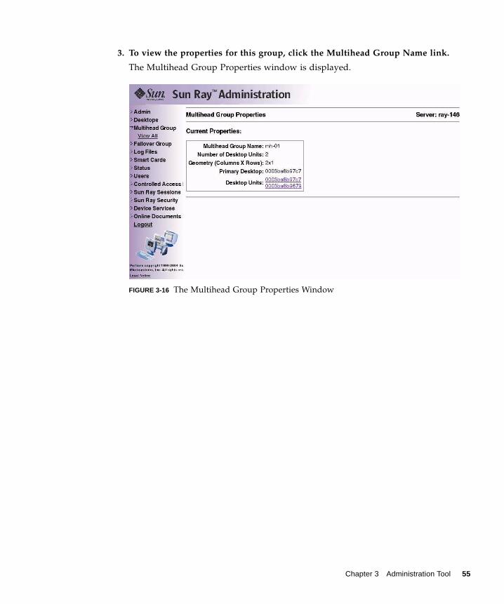
3. To view the properties for this group, click the Multihead Group Name link.
The Multihead Group Properties window is displayed.
FIGURE 3-16 The Multihead Group Properties Window
Chapter 3 Administration Tool 55

4. To display the Desktops Current Properties for the DTUs that are part of thisgroup, click the Desktop Units links.
The Desktops Current Properties window for the link selected is displayed.
FIGURE 3-17 Desktops Current Properties Window
The Multihead Group name is displayed as a property of this desktop.
Managing Sun Ray Device ServicesAll Sun Ray device services are enabled by default. Sun Ray device services includeUSB devices connected through USB ports, internal serial ports, and internal smartcard readers on the Sun Ray DTU.
To enable or disable these services, use the utdevadm command line tool (see“Enabling and Disabling Device Services” on page 24) or the Admin GUI as shownin this section.
▼ To Enable or Disable Sun Ray Device Services1. From the navigation menu, select the arrow to the left of the Device Services in
the navigation bar to expand the menu.
56 Sun Ray Server Software 3.1 Administrator’s Guide • September 2005

2. Click on Enable/Disable Services in the menu to display the USB Service window.
FIGURE 3-18 Device Services Window
3. Toggle the Disable or Enable radio button.
4. Click Apply to make the relevant change.
Note – Sun Ray services must be restarted before these changes can take effect.
Chapter 3 Administration Tool 57

Examining Log FilesSignificant activity concerning files retrieved from the Sun Ray server is logged andsaved. The server stores this information in text files. TABLE 3-1 describes the log filesthat are maintained.
TABLE 3-1 Log Files
Log File Path Description
Administration /var/opt/SUNWut/log/admin_log Lists operations performed during serveradministration. This log is updated daily.Archived files are stored on the system forup to one week and are annotated usingnumeric extensions (for example, fromfilename admin_log.0 toadmin_log.5).
Authentication /var/opt/SUNWut/log/auth_log Lists events logged from theAuthentication Manager. The auth_logfile is updated (up to a limit of 10) everytime the server’s authentication policy ischanged or started. The archivedauthentication files are annotated usingnumeric extensions (for example, fromauth_log.0 to auth_log.9).
Messages /var/opt/SUNWut/log/messages Lists events from the server’s DTUs,including details of registering, inserting,or removing smart cards. This file isupdated daily. Archived files are storedon the server for one week annotatedwith numeric extensions (for example,from messages.0 to messages.5).
58 Sun Ray Server Software 3.1 Administrator’s Guide • September 2005

▼ To View a Log File1. From the navigation menu, select the arrow to the left of Log Files to expand the
menu.
2. Choose the Log link you want to inspect: Messages, Auth Log, Admin Log, orArchived Logs, utmountd.log, or utstoraged.log.
The appropriate Log File window is displayed. Use the scroll bar to access data to theright and bottom of the window.
FIGURE 3-19 Administration Log File WindowAlthough this figure shows a log not currently available on Linux, other logs aredisplayed in a similar fashion.
Chapter 3 Administration Tool 59

Managing Smart CardsThe information provided about smart cards is extracted from vendor-suppliedconfiguration files. These configuration files are located in the directory:/etc/opt/SUNWut/smartcard. Configuration files must be formatted correctly,and file names must end with a .cfg suffix; for example, acme_card.cfg.
For certain vendors, the smart card may require additional software to enable theSun Ray Server Software to probe for it. If required, this optional software must besupplied as Java classes in a Jar file. This file must end with a .jar suffix and musthave the same pre-suffix filename as the .cfg file that contains its configurationinformation.
▼ To View or List Configured Smart Cards1. From the navigation menu, select the arrow to the left of Smart Cards to extend
the menu.
2. Click the View link.
The View Configured Smart Cards window is displayed. Smart cards are listed inprobe order, i.e., the order in which they are inspected.
60 Sun Ray Server Software 3.1 Administrator’s Guide • September 2005

FIGURE 3-20 The View Configured Smart Cards Window
From this window an administrator can see the current list of smart cards as well asthe supplier and version number for each card.
Chapter 3 Administration Tool 61

3. From the View Configured Smart Cards window, select the link for the smart card.
The main properties for the selected smart card are displayed in FIGURE 3-21.
FIGURE 3-21 Smart Card Properties Window
62 Sun Ray Server Software 3.1 Administrator’s Guide • September 2005

▼ To View The Smart Card Probe Order● From the navigation menu under Smart Cards, click the Probe Order link.
The Smart Card Probe Order window is displayed.
FIGURE 3-22 Smart Card Probe Order Window
Smart cards are probed in the order in which they appear in this list.
Tip – As you add more cards, you can change the order of the cards to move thoseused most often to the top of the list.
▼ To Change the Smart Card Probe Order1. Select a smart card and press the appropriate up and down button.
Clicking on the first and last buttons (from top to bottom) moves the selected card toeither the top or bottom of the list.
2. Restart Sun Ray services.
Chapter 3 Administration Tool 63

▼ To Add a Smart Card1. From the expanded navigation menu under Smart Cards click the Add link.
The Add Smart Cards to Probe List window is displayed.
FIGURE 3-23 Add Smart Card to Probe List Window
2. Select a smart card and click the Add button.
3. Restart Sun Ray services.
▼ To Delete a Smart Card1. From the expanded navigation menu under Smart Cards, click the Delete link.
The Delete Smart Card From Probe List window is displayed.
2. Select a smart card.
3. Click the Delete button.
4. Restart Sun Ray services.
64 Sun Ray Server Software 3.1 Administrator’s Guide • September 2005

Sun Ray System Status
▼ To View the Sun Ray System Status1. Click the directional arrow to the left of Status to expand the navigation menu.
2. Click the Summary Status link.
The Summary Status window is displayed.
FIGURE 3-24 Summary Status Window
Chapter 3 Administration Tool 65

Administering UsersYou can specify the following user fields in the Sun Ray administration database:
TABLE 3-2 Key User Fields
Field Description
Token ID User’s unique token type and ID. For smart cards, this is a manufacturertype and the card’s serial ID. For DTUs, this is the type “pseudo” and theDTU’s Ethernet address. Examples:mondex.9998007668077709pseudo.080020861234
Server Name Name of the Sun Ray server that the user is using.
Server Port Sun Ray server’s communication port. This field should generally be set to7007.
User Name User’s name.
Other Info Any additional information you want to associate with the user (forexample, an employee or department number). This field is optional.
66 Sun Ray Server Software 3.1 Administrator’s Guide • September 2005
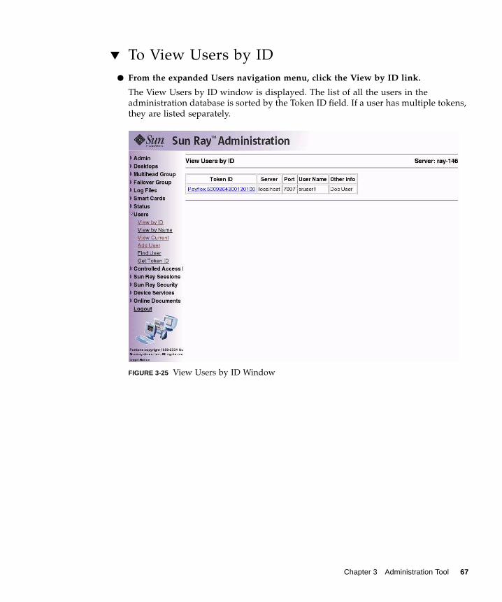
▼ To View Users by ID● From the expanded Users navigation menu, click the View by ID link.
The View Users by ID window is displayed. The list of all the users in theadministration database is sorted by the Token ID field. If a user has multiple tokens,they are listed separately.
FIGURE 3-25 View Users by ID Window
Chapter 3 Administration Tool 67

▼ To View Users by Name● From the expanded Users navigation menu, click the View by Name link.
The View Users by Name window is displayed, listing all the users in theadministration database sorted by the User Name field. If a user has multiple tokens,they are grouped together with the name.
FIGURE 3-26 View Users by Name Window
68 Sun Ray Server Software 3.1 Administrator’s Guide • September 2005

▼ To Delete a User
Caution – This operation deletes the user and all associated tokens.
1. From the View by Name window, click the User Name of the user you want todelete.
The Current Properties window displays information about the user, host, token,and allows the administrator to edit the user’s properties, delete the user, and viewthe user’s session.
FIGURE 3-27 The Current Properties Window Shows Administrative Options for a User
Chapter 3 Administration Tool 69
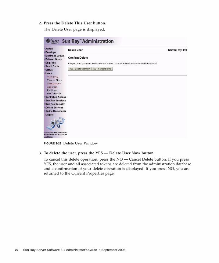
2. Press the Delete This User button.
The Delete User page is displayed.
FIGURE 3-28 Delete User Window
3. To delete the user, press the YES — Delete User Now button.
To cancel this delete operation, press the NO — Cancel Delete button. If you pressYES, the user and all associated tokens are deleted from the administration databaseand a confirmation of your delete operation is displayed. If you press NO, you arereturned to the Current Properties page.
70 Sun Ray Server Software 3.1 Administrator’s Guide • September 2005

▼ To View Current Users● From the expanded navigation menu under Users, click the View Current link.
The View Current Users window is displayed, listing users who currently haveactive sessions.
Note – The list of users conforms to policies established with utpolicy, with whichyou can enable display of registered users, unregistered users, or both.
FIGURE 3-29 View Current Users Window
▼ To Display a User’s Current Properties● Click the Token ID or User Name hyperlink for the user.
The Current Properties page for the user is displayed (see FIGURE 3-27). It displaysthe information about the user contained in the administration database, includingthe user’s current login status.
The possible states are:
■ Never Logged In■ Currently Logged In
Chapter 3 Administration Tool 71

■ Logged Off
For the last two states, the following fields are also displayed:
▼ To Add a User1. From the expanded menu under Users, click the Add User link.
The Add User window is displayed.
FIGURE 3-30 Add User Window
2. If you do not know the user’s Token ID and have configured a token reader:
a. Insert the user’s new card into the selected token reader.
TABLE 3-3 Login Status Fields
Option Description
Current Desktop/Last Desktop Current/last DTU where the user is or was logged in.
Desktop Location Location of the DTU.
Logged In Since/Logged Off At Date and time the user logged in or off the DTU.
72 Sun Ray Server Software 3.1 Administrator’s Guide • September 2005

b. Choose the selected token reader from the pull-down menu of availablereaders.
c. Press the Get Token ID button.
The application queries the token reader and, if successful, redisplays the formwith the Token ID field filled out.
3. Enter data in the required fields.
4. Press the Add User button.
The user and associated token are created in the administration database.
Note – In releases prior to SRSS 3, access to the token card reader was limited to theserver to which it was connected. In other words, you had to use the Admin GUI ofthat server. Beginning with SRSS 3.1, however, you can access the token card readerby invoking the Admin GUI of any server in the relevant failover group.
▼ To View the User’s Sessions● If the user is currently logged in, view the user’s session by clicking the View
This User’s Session button.
Chapter 3 Administration Tool 73

▼ To Edit a User’s Properties1. From the user’s Current Properties page, press the Edit Properties button.
The Edit User Properties page is displayed.
FIGURE 3-31 Edit User Properties Page
2. Make changes to any of the text boxes.
You can also add or remove tokens from a user at the same time.
3. When finished, press the Save Changes button.
The changes are saved to the administration database.
▼ To Add a Token ID to a User’s Properties1. From the Edit User Properties page, type the new Token ID into the empty Token
ID text field.
2. If you do not know the new Token ID and have configured a token reader:
a. Insert the user’s new card into the selected token reader.
74 Sun Ray Server Software 3.1 Administrator’s Guide • September 2005

b. Choose the selected token reader from the pull-down menu of availablereaders.
c. Press the Get Token ID button.
The application queries the token reader and, if successful, redisplays the formwith the Token ID text field filled out.
3. Check the Enabled checkbox next to the new Token ID.
4. Check the Add checkbox next to the new Token ID.
You can also make any other edits to the user at the same time.
5. Press the Save Changes button.
The changes are then added to the administration database.
▼ To Delete a Token ID From a User’s Properties1. From the Edit User Properties page, check the Remove checkbox for any token IDs
you want to remove.
2. Press the Save Changes button.
The changes are then added to the administration database.
▼ To Enable or Disable a User’s Token1. From the Edit User Properties page, check the Enabled checkbox for any token IDs
you want to enable.
2. Uncheck the Enabled checkbox for any token IDs you want to disable.
3. Press the Save Changes button.
The changes are saved to the administration database.
Chapter 3 Administration Tool 75

▼ To Find a User1. From the expanded menu under Users, click the Find link.
The Find User window is displayed.
FIGURE 3-32 Find User Window
2. Enter data in the required fields.
3. Press the Search button.
76 Sun Ray Server Software 3.1 Administrator’s Guide • September 2005

▼ To Get a Token ID From a Token Reader1. From the expanded Users menu, click the Get Token ID link.
The Get Token ID window is displayed.
FIGURE 3-33 Get Token ID Window
2. Insert the new card into the selected token reader.
3. Choose the selected token reader from the pull-down menu of available readers.
4. Press the Get Token ID button.
The application queries the token reader and redisplays the page with the Token IDfield filled out.
Chapter 3 Administration Tool 77

Managing SessionsA Sun Ray session is created when the user logs in to a Sun Ray DTU. The possiblestates for a Sun Ray session are shown in TABLE 3-4.
▼ To Find Sun Ray Sessions1. From the navigation menu, click the expansion arrow for Sun Ray Sessions.
2. From the expanded navigation menu, click the Find Sun Ray Sessions link.
3. In the text fields, enter the User Name, Token ID, or Unix Login Name.
4. Click the Search button.
If you enter data in error, press the Clear button to clear entered data. The Sun RaySessions window is displayed with the Sun Ray search results.
TABLE 3-4 Sun Ray Session States
State Description
Connected/disconnected A session is currently displayed on a DTU.
Idling The session is waiting at the GDMlogin prompt.
78 Sun Ray Server Software 3.1 Administrator’s Guide • September 2005

▼ To View Sun Ray Sessions1. From the navigation menu, click the expansion arrow for Sun Ray Sessions.
2. From the expanded navigation menu, click the View by Server link.
Running sessions on the current server are displayed.
FIGURE 3-34 Sessions on Current Sun Ray Server Window
3. To change the state of any of the displayed sessions, use the Action pull-downmenu button to display your choices.
There are three possible actions: None, Terminate, and Suspend.
4. To apply your changes, click the Apply button.
Chapter 3 Administration Tool 79

80 Sun Ray Server Software 3.1 Administrator’s Guide • September 2005

CHAPTER 4
Peripherals for Sun Ray DTUs
This chapter contains information about selected USB, parallel, and serial devicesand printing from Sun Ray DTUs.
■ “Device Nodes and USB Peripherals” on page 81■ “Attached Printers” on page 84■ “Adapters” on page 86
There are two kinds of peripherals: serial and parallel. Serial peripherals enableRS-232-style serial connections to the Sun Ray DTU. Parallel peripherals enableprinting and come in two types: adapters and direct USB-connected printers.
Third-party adapters are useful for supporting legacy serial and parallel devices.
Sun Ray Server Software recognizes a parallel printer with an adapter as a USBprinter.
Device Nodes and USB PeripheralsSun Ray Server Software creates a device directory called IEEE802.MACID in the/tmp/SUNWut/units directory. This directory contains the MAC address foreach DTU on the interconnect. The IEEE802.MACID directory for each DTUcontains dev and devices directories. The Sun Ray dev directory contains arepresentation of the logical topology of the devices connected to the DTU. TheSun Ray devices directory contains a representation of the physical topology ofsome of the devices connected to the DTU.
Note – Sun Ray Server Software does not create device nodes for every USB device.Some USB device drivers export their device interfaces through other mechanismsthan a traditional UNIX device node.
81

Directories correspond to buses and hubs, and files correspond to ports. Hubdirectories are named according to the port on the upstream hub into which they areattached.
Device NodesIn Sun Ray devices, device nodes are created for each serial or printer port on anattached USB device. The device nodes are created in the hub directorycorresponding to the hub to which they are attached. They are named:
If the USB device has multiple identical ports (for example, two serial ports), thename is followed by :n where n is a numerical index, starting at 1.
The following is a typical device node path:
Device LinksDevice links are created under the dev directory. A link to each serial node is createdin dev/term, and a link to each parallel node is created in dev/printers.
manufacturer_name, model_name@upstream_hub_port
/tmp/SUNWut/units/IEEE802.MACID/devices/usb@1/hub@1/\manufacturer_name, model_name@3:1
TABLE 4-1 Definitions of Naming Conventions
Term Definition
physical topology The physical topology is hub@port/hub@port and so on. The portrefers to the port on the parent hub into which the device orchild hub is plugged.
printer name 1, terminal name 1 The printer and terminal name in the Sun Ray devicesdirectory is manufacturer, model@port with a colon separating thenumerical index when the string just described is not unique inthe directory.
printer name 2, terminal name 2 The printer and terminal name in the Sun Ray dev directory isthe manufacturer and serial number concatenated with analphabetic index when the serial number is not unique.
82 Sun Ray Server Software 3.1 Administrator’s Guide • September 2005

Typical device links are:
where index is an increasing alphabetical character, starting at a.
If the manufacturer name is not available, the USB vendor and product ID numbersare used for the name of the device link.
Device Node OwnershipSome device nodes are owned by the user whose session is active on the DTU, whileothers may be owned by root or by other users that may have had previously activesessions on the DTU. Device permissions, access controls and ownership rules aredetermined by the class of device. For serial and parallel devices, only the userwhose session is active on the DTU or the superuser have permission to use theattached device. If there is no user with an active session, superuser owns the serialand parallel device nodes. This rule may not hold for other classes of USB devicesconnected to the DTU.
Hotdesking and Device Node Ownership
Note – The following description of the behavior of USB devices when sessions areconnected and disconnected from a DTU applies only to USB serial and USB paralleldevices. Other device classes may have different semantics regarding ownership anddevice lease times.
Changing the active session on a DTU changes the ownership of the device nodes tothe user associated with the new session. A session change occurs whenever a user:
■ Inserts or removes a smart card from a DTU■ Logs into a session■ Detaches from a session using non-smart card mobility
/tmp/SUNWut/units/IEEE802.080020cf428a/dev/term/manufacturer_name-67a/tmp/SUNWut/units/IEEE802.080020cf428a/dev/printers/1608b-64
manufacturer_name-serial_numberindex
Chapter 4 Peripherals for Sun Ray DTUs 83

In a failover environment, you can use the utselect or utswitch command tochange a session. A session change causes all devices currently open by a non-rootuser to be closed after 15 seconds. Any input or output to or from any affecteddevice results in an error. Devices currently opened by the superuser remainunaffected by the session change.
Note – When a session is changed, any input or output in progress on a device nodeopened by a non-root user is cancelled after 15 seconds. If the original session isrestored within 15 seconds, the ownership is not relinquished, and input and outputcontinue uninterrupted.
Attached PrintersSun Ray Server Software supports PostScript™ printers connected directly to a USBport on the Sun Ray DTU or connected through a USB-to-parallel port adapter. Fornon-PostScript printer support, refer to “Printers Other Than PostScript Printers” onpage 85.
Note – The lp subsystem opens the device node as superuser for each print request,so print jobs are not affected by hotdesking.
Printer SetupThe following generic instructions may vary slightly from one operating systemimplementation to another but should provide enough information to enable anadministrator to set up basic printing services.
▼ To Set Up a Printer
1. Log in as superuser on a Sun Ray DTU.
2. To determine the MAC address of the DTU, press the three audio option keys tothe left of the power key in the upper right corner of the keyboard.
The alphanumeric string displayed above the connection icon is the MAC address.
84 Sun Ray Server Software 3.1 Administrator’s Guide • September 2005

3. To locate the Sun Ray DTU, type:
The path to the extended MAC address for your particular Sun Ray DTU isdisplayed.
4. Locate the port for the printer by typing:
5. In the directory, locate the printer node.
6. Use the Linux administration tools to set up the printer.
Make sure to choose Other so that you can enter the device node from Step 4 above.
7. To verify that the printer has been set up correctly, type:
Printers Other Than PostScript PrintersPrinters that do not use PostScript, such as engineering plotters, are best supportedby third-party software. Low-cost inkjet printers require third-party software suchas:
■ Easy Software’s ESP PrintPro, available from http://www.easysw.com■ Ghostscript, available from http://www.ghostscript.com■ Vividata PShop, available from http://www.vividata.com
Check with the vendors for pricing and the precise printer models supported.
# cd /tmp/SUNWut/units/*MAC_address# pwd /tmp/SUNWut/units/IEEE802.MACID/
# cd dev/printers# pwd/tmp/SUNWut/units/IEEE802.MACID/dev/printers#lsprinter-node-name
# lpstat -d printername
Chapter 4 Peripherals for Sun Ray DTUs 85

AdaptersFor a list of verified serial and parallel adapters, see:
http://www.sun.com/io_technologies/sunray/usb/sunray-index.html
libusblibusb is an Open Source user space USB API that enables applications to access USBdevices. It has been implemented for a number of operating environments includingLinux, BSD Unix, and Solaris.
The Sun Ray libusb plugin libusbut.so.1 provides Sun Ray-specific support forlibusb in Linux environments.
The SUNWlibusbut RPM delivers the Sun Ray libusb plugin libusbut.so.1 in/opt/SUNWut/lib. To build applications, use the usb.h header file from theexisting server-side Linux libusb RPM.
The libusbut man page provided with SRSS 3.1 for Linux discusses options availablefor using the Sun Ray libusb plugin alongside the Linux server-side libusbsupport.
The Open Source libusb-based applications provided with the standard Linuxdistributions can be used to drive USB-based devices attached to Sun Ray DTUs. Forexample, for Sane, see www.sane-proj.org; for Gphoto, see www.gphoto.org.
Note – Sane can be used in Sun Ray implementations if built with threads enabled.Sane binaries with threads enabled are available at the Sun Download Center(SDLC), or they can be built from source.
86 Sun Ray Server Software 3.1 Administrator’s Guide • September 2005

CHAPTER 5
Hotdesking (Mobile Sessions)
The Sun Ray system is designed to enable session mobility, or hotdesking, withSmart Cards. Every Sun Ray DTU is equipped with a Smart Card reader.
This chapter describes how to enable users to access their Sun Ray sessions not onlywithin a failover group (see “Failover Groups” on page 143) but across multiplefailover groups. This feature is called regional hotdesking.
Regional HotdeskingRegional hotdesking can be enabled by means of multiple failover groups. Multiplefailover groups are useful for various reasons, such as:
■ Availability
It is sometimes advantageous to have multiple, geographically-separate locations,each with a failover group, so that if an outage occurs at one location, anotherlocation can continue to function.
■ Organizational Policies
Some sites have different administrative policies at different locations. It can beadvantageous to keep separate failover groups at these locations.
Regional hotdesking, sometimes referred to as Automatic Multi-Group Hotdesking(AMGH), is useful when an enterprise has multiple failover groups and users whomove from one location to another who wish to gain access to their existing sessionwherever they roam. The following sections describe regional hotdesking. Forfurther technical detail, please refer to the utamghadm(8),ut_amgh_get_server_list(3), and ut_amgh_script_interface(3) manpages.
87

Note – Regional hotdesking is not enabled for multihead groups.
Functional OverviewOnce regional hotdesking is configured, user login information and sessions arehandled as follows:
1. When a smartcard is inserted or removed from the system or a user logs in via thegreeter GUI, parameters such as the username (if known at the time), smartcardtoken, and terminal identifier are passed to a piece of site-integration logic.
2. The site-integration software uses these parameters to determine to which SunRay servers it should direct the Sun Ray DTU.
3. If the smart card token is associated with a local session, then that session getspreference, and regional hotdesking is not invoked.
4. Otherwise, the regional hotdesking software redirects the Sun Ray DTU toconnect to the appropriate Sun Ray server.
Thus, if the user has an existing session, the DTU connects to that session; if not, theregional hotdesking software creates a new session for that user.
Site RequirementsTo utilize regional hotdesking, a site must provide some site integration logic thatcan utilize enterprise data to determine which users or Sun Ray DTUs shouldconnect to which failover groups. This is ordinarily provided through the use of adynamic C library or a shell script that implements a particular interface used byregional hotdesking software. SRSS provides some reference code that a siteadministrator can use as an example or adapt as required. An administrator mustconfigure the regional hotdesking software to utilize a specified library or shellscript, then implement the PAM stack of the login applications, as described below.
Note – To ensure continuous operation, the be sure to include enough servers in thetarget group to provide availability for session location and placement in the eventthat a particular server becomes unavailable. Two servers should be minimallysufficient for most sites; three servers provide a conservative margin of error.
88 Sun Ray Server Software 3.1 Administrator’s Guide • September 2005

Providing Site Integration LogicTo determine where given Sun Ray DTUs or users should be connected whencreating or accessing sessions, the administrator must utilize enterprise data. SunRay Server Software 3.1 includes for this purpose:
■ man pages, such as ut_amgh_get_server_list(3),which describe theappropriate C API for a shared library implementation
■ A shell-script API, ut_amgh_script_interface(3), which can be used as analternative.
■ Reference C code and script code, located at /opt/SUNWutref/amgh. This codecan serve as example or be directly adapted for use.
■ A functional Makefile.
▼ To Configure a Site-specific Mapping Library
The administrator for each site must determine what mapping library to use. It maybe a site-specific implementation, as described above, or one of the sampleimplementations provided with the SRSS software.
Use the /opt/SUNWut/sbin/utamghadm command to configure the regionalhotdesking software to use this library.
1. To configure the token-based mapping implementation provided as a sample,execute the following:
2. To configure the username-based mapping implementation provided as a sample,execute the following:
3. To configure a script-based back-end mapping (for example, the token-and-username-combination-based mapping sample), use the -s option to thiscommand:
4. Do a cold restart of the SRSS services using either the utrestart CLI or the AdminGUI.
# /opt/SUNWut/sbin/utamghadm -l/opt/SUNWutref/amgh/libutamghref_token.so
# /opt/SUNWut/sbin/utamghadm -l/opt/SUNWutref/amgh/libutamghref_username.so
# /opt/SUNWut/sbin/utamghadm -s /opt/SUNWutref/amgh/utamghref_script
Chapter 5 Hotdesking (Mobile Sessions) 89
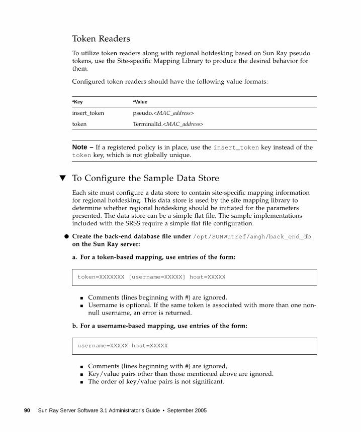
Token Readers
To utilize token readers along with regional hotdesking based on Sun Ray pseudotokens, use the Site-specific Mapping Library to produce the desired behavior forthem.
Configured token readers should have the following value formats:
Note – If a registered policy is in place, use the insert_token key instead of thetoken key, which is not globally unique.
▼ To Configure the Sample Data Store
Each site must configure a data store to contain site-specific mapping informationfor regional hotdesking. This data store is used by the site mapping library todetermine whether regional hotdesking should be initiated for the parameterspresented. The data store can be a simple flat file. The sample implementationsincluded with the SRSS require a simple flat file configuration.
● Create the back-end database file under /opt/SUNWutref/amgh/back_end_dbon the Sun Ray server:
a. For a token-based mapping, use entries of the form:
■ Comments (lines beginning with #) are ignored.■ Username is optional. If the same token is associated with more than one non-
null username, an error is returned.
b. For a username-based mapping, use entries of the form:
■ Comments (lines beginning with #) are ignored,■ Key/value pairs other than those mentioned above are ignored.■ The order of key/value pairs is not significant.
*Key *Value
insert_token pseudo.<MAC_address>
token TerminalId.<MAC_address>
token=XXXXXXX [username=XXXXX] host=XXXXX
username=XXXXX host=XXXXX
90 Sun Ray Server Software 3.1 Administrator’s Guide • September 2005

c. For a combined mapping, use entries of the form:
■ Comments (lines beginning with #) are ignored,■ A TOKEN match is attempted first.■ If none is made (or if no username is included in the matches) the user is
prompted for a username.■ A lookup is made for this username. If there is no match, a local session is
created; otherwise, the Sun Ray DTU is forwarded to the first host reported asavailable.
A sample line for this file would look like the following:
▼ To Disable Regional Hotdesking
1. To disable AMGH configuration for a group, run the following command:
2. Do a cold restart of the SRSS services using either the utrestart CLI or the AdminGUI.
Any combination of TOKEN BASED and USERNAME BASED lines.
token=MicroPayflex.5001436700130100 username=user1 host=ray-207
% /opt/SUNWut/sbin/utamghadm -d
Chapter 5 Hotdesking (Mobile Sessions) 91

92 Sun Ray Server Software 3.1 Administrator’s Guide • September 2005

CHAPTER 6
Encryption and Authentication
Sun Ray Server Software provides interconnect security. Two main aspects of thisfeature are:
■ Traffic encryption between the Sun Ray client and server■ Sun Ray server-to-client authentication
IntroductionIn earlier versions of Sun Ray Server Software, data packets on the Sun Rayinterconnect were sent in the clear. This made it easy to “snoop” the traffic andrecover vital and private user information, which malicious users might misuse. Toavoid this type of attack, Sun Ray Server Software allows administrators to enabletraffic encryption. This feature is optional; the system or network administrator canconfigure it based on site requirements.
The ARCFOUR encryption algorithm, selected for its speed and relatively low CPUoverhead, supports a higher level of security between Sun Ray services and Sun Raydesktop units. In the Sun Ray Server Software 2.0 release, only the X server trafficwas encrypted.
Encryption alone does not provide complete security. It is still possible, if notnecessarily easy, to spoof a Sun Ray server or a Sun Ray client and pose as either.This leads to the man-in-the- middle attack, in which an impostor claims to be theSun Ray server for the clients and pretends to be client for the server. It then goesabout intercepting all messages and having access to all secure data.
Client and server authentication can resolve this type of attack. This release offersserver-side authentication only, through the pre-configured public-private key pairsin Sun Ray Server Software and firmware. The Digital Signature Algorithm (DSA) isused to verify that clients are communicating with a valid Sun Ray server. This
93

authentication scheme is not completely foolproof, but it mitigates trivial man-in-the-middle attacks and makes it harder for attackers to spoof Sun Ray ServerSoftware.
Security ConfigurationWhen configuring the security for a Sun Ray system, you should evaluate thesecurity requirements. You may choose:
■ to enable encryption for upstream traffic only■ to enable encryption for downstream traffic only■ to enable bidirectional encryption■ to enable server authentication (client authentication is not currently available)
Additionally, you must decide whether to enable hard security mode. To configureyour site, you can use the utcrypto command or the Sun Ray Administration Tool(Admin GUI).
Security ModeHard security mode ensures that every session is secure. If security requirementscannot be met, the session is refused. Soft security mode ensures that every clientthat requests a session gets one; if security requirements cannot be met, the session isgranted but not secure.
For example, in hard security mode, if any Sun Ray DTU that does not supportsecurity features (for instance, because of old firmware) connects to a Sun Rayserver, the server denies the session.
In soft security mode, given the above situation, the Sun Ray server grants the DTUa non-secure session. It is now up to the user to decide whether to continue using anon-secure session.
For more information, please see the man page for utcrypto or “AdministrationTool” on page 37.
94 Sun Ray Server Software 3.1 Administrator’s Guide • September 2005

FIGURE 6-1 Sun Ray Security Configuration Window
Session SecurityUse the utsession command to display session status. Its output has beenmodified to included security status for a session. The State column in utsession-p output now displays the encrypted/authenticated state of the session by using Efor encrypted and A for authenticated session types. This information is notdisplayed for any session in the disconnected state.
In a multihead environment, there may be a case where the primary and thesecondary servers have different firmware. For instance, if the secondary has version1.3 or earlier firmware, it cannot support any of the security features. In this case, thelowest security setting is displayed. In other words, if the secondary server isconfigured with 1.3 firmware and the primary server with 2.0, 3.0, or SRSS 3.1firmware, and encryption and authentication are configured, then neither an E or anA is displayed.
# utsession -pToken ID Registered NameUnix IDDisp StatePayflex.0000074500000202 ??? ??? 2IEAMicropayflex.000003540004545??????3D
Chapter 6 Encryption and Authentication 95

Security StatusOnce a connection has been successfully established between a client and a server,the user can determine whether the connection is secure at any time by pressing thethree volume keys together (currently used to determine MAC address of theterminal).
One of the following icons is also displayed when a Sun Ray DTU connects to asession. Each icon displays information about connection security status.
There are several variations on the security icon:
Locked Authenticated
The server is authenticated to the client and the data linkis encrypted.
Locked Not Authenticated
The server is not authenticated to the client and the datalink is encrypted.
Unlocked Not Authenticated
The server is not authenticated to the client and the datalink is not encrypted.
96 Sun Ray Server Software 3.1 Administrator’s Guide • September 2005

Unlocked Authenticated
The server is authenticated to the client but the data linkis not encrypted.
Session Connection FailuresThe following icons are displayed when there might be a security breach.
Session Refused
Definition: The client is refusing to connect to a serverbecause it is unable to verify the validity of the Sun Rayserver.
This error can occur only if an unknown Sun Ray serverintercepts the messages and tries to emulate a valid SunRay server. This is a session security breach.
Session Refused
Definition: The server is refusing to grant a session to theclient because the client is unable to fulfill the server’ssecurity requirements.
Actions to take:
■ Check the client’s firmware version. This error may occur with firmwareversions earlier than 2.0 if the server is configured for hard security mode.
■ Upgrade the firmware to version 2.0 or later, preferably to SRSS 3.1. As analternative, confirm whether your site requires hard security mode. If not, thesession can be enabled with soft security mode.
Chapter 6 Encryption and Authentication 97

98 Sun Ray Server Software 3.1 Administrator’s Guide • September 2005

CHAPTER 7
Gnome Display Manager
The Gnome Display Manager (GDM) is responsible for logging users into yoursystem and starting their sessions (an X11 server plus applications). It is typicallyused to manage the console on a system that is configured with a graphics device,but it may be used to manage other displays attached to a system as well.
Unfortunately the version of GDM that is supplied with your system is not able towork in a Sun Ray environment. Therefore, the Sun Ray server software includes aGDM that has been enhanced with the ability to manage Sun Ray devices. Thisenhanced GDM is otherwise identical to the GDM it replaces, and can still be used tomanage the console and/or other displays.
InstallationDuring the SRSS installation process, you will be asked whether the installationscript should remove the existing GDM from your system. You must answer “yes” tothis question in order to continue with the SRSS installation. SRSS will then removethe old GDM from your system and install the Sun Ray-enhanced version. If youanswer “no”, the SRSS install process will be aborted.
Since the existing GDM will be removed during SRSS install, it is recommended thatyou not use a GDM-controlled display to do the install. Use a telnet session into theserver, or a virtual terminal.
Caution – Sun Ray Server Software requires its own Sun Ray-enhanced GnomeDisplay Manager. If you update your system with a newer GDM, SRSS will not beable to run, and DTUs with 2.0 or newer firmware will display the 26D icon.
Tip – If you are using an automatic update system, such as Red Hat’s up2date, youmay wish to alter your configuration files to ignore GDM.
99
UninstallationIf you need to remove the SRSS software, you will be asked whether the Sun Ray-enhanced GDM should remain on your system. If you answer “no”, be advised thatyou may have to install the original GDM RPM if you want non-Sun Ray displays,such as the console, to be managed.
ConfigurationThe Sun Ray GDM is based on version 2.4.4.7. If you have already upgraded yoursystem to a newer version of GDM, the Sun Ray version may not have all thefeatures you expect.
Sun Ray installation will remove the current GDM from your system, including itsconfiguration file, /etc/X11/gdm/gdm.conf (or /etc/gnome2/gdm/gdm.confon Suse systems)
Therefore, if you have modified to your gdm.conf configuration, backup the filebefore installing SRSS. You may wish to reapply your changes to the gdm.conf thatSRSS installs.
Tip – Do not simply put your old gdm.conf in place of the SRSS-installed one, SunRay Server Software will not work correctly.
The default configuration for GDM is to manage DISPLAY 0 (zero) on the console.If you do not wish to start an X11 server on the console, edit/etc/X11/gdm/gdm.conf and remove DISPLAY 0 from the servers section.
Gnome Display Manager PrivilegesMany Linux systems come configured with liberal administrative privileges for non-root users. You most likely do not want these privileges offered to users who loginusing a Sun Ray. Please review the man pages for pam_console, console.perms,and console.apps. It is also a good idea to edit the/etc/security/console.perms file to remove display numbers from thedefinition of console. If a definition exists for xconsole, it should be removed entirely.
For example, a line that reads:
<console>=tty[0-9][0-9]* vc/[0-9][0-9]* :[0-9]˙[0-9] :[0-9]
should instead read:
<console>=tty[0-9][0-9]* vc/[0-9][0-9]*
100 Sun Ray Server Software 3.1 Administrator’s Guide • September 2005

And a line such as:
<xconsole>=:[0-9]˙[0-9] :[0-9]
should be removed altogether.
Chapter 7 Gnome Display Manager 101

102 Sun Ray Server Software 3.1 Administrator’s Guide • September 2005

CHAPTER 8
Deployment on Shared Networks
This chapter describes the process of deploying DTUs on shared network segments.It covers the following topics:
■ “Sun Ray DTU Initialization Requirements” on page 103■ “Network Topology Options” on page 106■ “Network Configuration Tasks” on page 109■ “Network Performance Requirements” on page 126■ “Troubleshooting Tools” on page 127■ “Enhancements to Firmware Download and Configuration Support” on page 130
When first introduced, Sun Ray DTUs could be deployed only on dedicated,directly-connected interconnect subnets. Although dedicated interconnects providereliable service and are easy to configure, they require the full-time commitment ofnetworking equipment, cabling, and host interfaces. This constraint has beenremoved from SRSS 2.0 and later releases, allowing network administrators todeploy Sun Ray DTUs nearly anywhere on an enterprise intranet. The mostimportant advantages of intranet deployment are:
■ Sun Ray can be deployed on any existing network infrastructure that meets SunRay Quality of Service (QoS) requirements.
■ Sun Ray DTUs can be deployed at a greater distance from their Sun Ray server.
Sun Ray DTU InitializationRequirementsBecause Sun Ray DTUs are stateless, they rely entirely on network services toprovide the configuration data they need to complete their initialization.
■ Each DTU must first acquire basic network parameters, such as a valid IPaddress, on the network to which it is connected.
103

■ The DTU can also be supplied with additional configuration information tosupport advanced product features, such as the ability to update the DTUfirmware and to report exception conditions to a syslog service.
■ The DTU must locate and contact a Sun Ray server that can offer desktop servicesto the Sun Ray user.
The Sun Ray DTU uses the Dynamic Host Configuration Protocol (DHCP) to obtainthis information.1
DHCP BasicsThe DTU is a DHCP client that solicits configuration information by broadcastingDHCP packets on the network. The requested information is supplied by one ormore DHCP servers in response to the client’s solicitations. DHCP service may beprovided by a DHCP server process executing on a Sun Ray server, by DHCP serverprocesses executing on other systems, or by some combination of the two. Anyconforming implementation of a DHCP service can be used to satisfy the DHCPrequirements of the DTU. Sun's Solaris DHCP service is one such implementation.Third-party implementations executing on non-Sun platforms can also be configuredto deliver information to Sun Ray DTUs.
The DHCP protocol defines a number of standard options that can be used to informthe client of a variety of common network capabilities. DHCP also allows for anumber of vendor-specific options (see TABLE 8-2), which carry information that ismeaningful only to individual products.
The Sun Ray DTU depends on a small number of standard options to establish itsbasic network parameters. It depends on several standard and vendor-specificoptions to provide the additional information that constitutes a complete DTUconfiguration. If these additional configuration parameters are not supplied, theDTU cannot perform certain activities, the most important of which is thedownloading of new DTU firmware. TABLE 8-2 lists the vendor-specific options.
Note – If an administrator chooses not to make this additional configurationinformation available to the Sun Ray DTUs, a procedure must be established todeliver firmware updates to them. One solution would be a small, dedicatedinterconnect on one Sun Ray server. Then, the administrator can transfer the DTUsone-by-one when new firmware becomes available on the server, for instance,through a patch or Sun Ray product upgrade.
The location of the Sun Ray server is usually conveyed to the DTU through one of apair of DHCP vendor-specific options, AuthSrvr and AltAuth (see TABLE 8-2).
1. DHCP is an Internet Engineering Task Force (IETF) protocol described in Requests for Comments (RFC) RFC2131 and RFC 2132.
104 Sun Ray Server Software 3.1 Administrator’s Guide • September 2005

If the DTU does not receive this information, it uses a broadcast-based discoverymechanism to find a Sun Ray server on its subnet. The DTU firmware now goes onestep further. If the broadcast-based discovery mechanism fails, the DTU interpretsthe DHCP standard option (option 49) of the X Window Display Manager as a list ofSun Ray server addresses where it attempts to contact Sun Ray services (see“Configure the external DHCP service.” on page 122). This can simplify the DHCPconfiguration of LAN-deployed Sun Rays by removing the need for a DHCP vendoroption to carry this information (see TABLE 8-1).
DHCP Parameter DiscoveryDHCP enables two stages of parameter discovery. The initial DHCPDISCOVER stagediscovers basic network parameters. This stage may be followed by a DHCPINFORM,which finds additional information that was not provided during DHCPDISCOVER.
All Sun Ray DTUs must have access to at least one DHCP service, which providesnetwork parameters in response to a DHCPDISCOVER request from the DTU. DTUscontaining firmware delivered with Sun Ray Server Software 2.0 or later can exploitthe DHCPINFORM feature. They enable full configuration of the DTU, even when anexternal DHCP service that is not capable of providing complete configuration dataprovides the network parameters of the DTU.
DTUs that contain pre-2.0 firmware require all of their configuration information inthe initial DHCPDISCOVER phase. They do not attempt a DHCPINFORM step. If thedeployment strategy requires a two-step DHCP interaction, such DTUs must beupgraded with Sun Ray Server Software firmware version 2.0 or later before beingdeployed on a shared subnet.
TABLE 8-1 DHCP Service Parameters Available
ParametersSun Ray ServerDHCP Service
External DHCPservice with vendor-specific options
External DHCP service withoutvendor-specific options No DHCP service
Basic networkparameters
Yes Yes Yes No
Additionalparameters(for firmwaredownload, etc.)
Yes Yes No No
Sun Ray serverlocation
Yes Yes Yes, through broadcastdiscovery or the X DisplayManager standard option
Yes, throughbroadcastdiscovery
Chapter 8 Deployment on Shared Networks 105

DHCP Relay AgentThe DTU sends DHCP requests as broadcast packets that propagate only on the localLAN segment or subnet. If the DTU resides on the same subnet as the DHCP server,the DHCP server can see the broadcast packet and respond with the information theDTU needs. If the DTU resides on a different subnet than the DHCP server, the DTUmust depend on a local DHCP Relay Agent to collect the broadcast packet andforward it to the DHCP server. Depending on the physical network topology andDHCP server strategy, the administrator may need to configure a DHCP RelayAgent on each subnetwork to which Sun Ray clients are connected. Many IP routersprovide DHCP Relay Agent capability. If a deployment plan requires the use of aDHCP Relay Agent, and the administrator decides to activate this capability on arouter, the appropriate instructions can be found in the router documentation,usually under the heading of “DHCP Relay” or “BOOTP forwarding.”2
In certain cases, an existing enterprise DHCP service provides the DTU with its IPaddress while a Sun Ray server provides it with firmware version details and SunRay server location. If a deployment plan calls for DHCP parameters to be providedto the DTU by multiple servers, and none of those servers is connected to the subnetwhere the DTU resides, the DHCP Relay Agent should be configured so that theDTUs subnet can deliver broadcasts to all the DHCP servers. For example, in routerscontrolled by a Cisco IOS Executive (see “Deployment on a Remote Subnet” onpage 117), the ip helper-address command activates a DHCP Relay Agent.Specifying multiple arguments to the ip helper-address command enablesrelaying to multiple DHCP servers.
Network Topology OptionsThere are three basic topology options for Sun Ray deployment. DTUs can bedeployed on:
■ a directly-connected dedicated interconnect.■ a directly-connected shared subnet.■ a remote shared subnet.
A Sun Ray server can support any combination of these topologies, which are shownin FIGURE 8-1.
2. DHCP is derived from an earlier protocol called BOOTP. Some documentation uses these namesinterchangeably.
106 Sun Ray Server Software 3.1 Administrator’s Guide • September 2005

FIGURE 8-1 Network Topologies for Sun Ray DTU Deployment
Note – Sun Ray traffic on shared networks is potentially more exposed to aneavesdropper than traffic on a dedicated Sun Ray interconnect. Modern switchednetwork infrastructures are far less susceptible to snooping activity than earliershared technologies, but to obtain additional security the administrator may chooseto activate Sun Ray's encryption and authentication features. These capabilities arediscussed in “Encryption and Authentication” on page 93.
Directly-connected dedicated interconnect
Directly-connected shared subnet
Remote shared subnet
Sun Ray server
Router Printer PC
Laptop PC
Chapter 8 Deployment on Shared Networks 107

Directly-Connected Dedicated InterconnectThe directly-connected dedicated interconnect—often referred to simply as aninterconnect—places DTUs on subnets that are:
■ directly connected to the Sun Ray server (that is, the server has a networkinterface connected to the subnet).
■ devoted entirely to carrying Sun Ray traffic. Prior to the release of Sun Ray ServerSoftware 2.0, this was the only officially supported Sun Ray topology.
The Sun Ray server, which guarantees the delivery of the full set of DTUconfiguration parameters, is always used to provide DHCP service for a dedicatedinterconnect.
Directly-Connected Shared SubnetSun Ray Server Software now supports DTUs on a directly-connected shared subnet, inwhich:
■ the Sun Ray server has a network interface connected to the subnet.■ the subnet may carry a mix of Sun Ray and non-Sun Ray traffic.■ the subnet is generally accessible to the enterprise intranet.
On a directly-connected shared subnet, DHCP service can be provided by the SunRay server, or some external server, or both. Since the Sun Ray server can seebroadcast DHCP traffic from the DTU, it can participate in DTU initializationwithout requiring a DHCP Relay Agent.
Remote Shared SubnetSun Ray Server Software now also supports DTUs on a remote shared subnet. On aremote shared subnet:
■ a Sun Ray server does not have a network interface connected to the subnet.■ the subnet can carry a mix of Sun Ray and non-Sun Ray traffic.■ all traffic between the server and the DTU flows through at least one router.■ the subnet is generally accessible to the enterprise intranet.
On a remote shared subnet, DHCP service can be provided by the Sun Ray server, bysome external server, or by both. For DHCP service on the Sun Ray server toparticipate in DTU initialization, a DHCP Relay Agent must be configured on theremote subnet, where it collects DHCP broadcast traffic and forwards it to the SunRay server.
108 Sun Ray Server Software 3.1 Administrator’s Guide • September 2005

Network Configuration TasksThe addition of directly-connected and remote shared subnet support allows DTUsto be deployed virtually anywhere on the enterprise intranet, subject only to theprovision of DHCP service and a sufficient quality of service between the DTU andthe Sun Ray server.
The following sections explain how to configure a network to support thesedeployment scenarios:
■ a directly-connected dedicated interconnect■ a directly-connected shared subnet■ a remote shared subnet
FIGURE 8-2 shows the overall topology and configuration tasks.3
Preparing for DeploymentBefore deploying a DTU onto any subnet, the administrator must answer threequestions:
1. From which DHCP server will DTUs on this subnet get their basic IP networkingparameters?
2. From which DHCP server will DTUs on this subnet get additional configurationparameters to support features such as firmware download?
3. How will DTUs on this subnet locate their Sun Ray server?
The answers to these questions determine what configuration steps will let DTUsplaced on this subnet initialize themselves and offer Sun Ray sessions to users.
The following sections present examples of DTU deployment on the directly-connected dedicated interconnect A, the directly-connected shared subnet B, and theremote shared subnets C and D shown in FIGURE 8-2.
3. The /24 suffix in IP addresses indicates the use of Classless Inter Domain Routing (CIDR) notation, which isdocumented in IETF RFCs 1517, 1518, and 1519
Chapter 8 Deployment on Shared Networks 109

FIGURE 8-2 Sun Ray Network Topology
Deployment on a Directly-Connected DedicatedInterconnectSubnet A in FIGURE 8-2 is a directly-connected dedicated interconnect. Its subnet willuse IP addresses in the range 192.168.128.0/24. The Sun Ray server named heliosis attached to the interconnect through its qfe2 network interface, which will beassigned the IP address 192.168.128.3.
Directly-connected dedicated interconnect
Directly-connected shared subnet
Remote shared subnet
Sun Ray server������
Routerr22-59
Remote shared subnet
Routerr22-71
qfe2192.168.128.3
hme0130.146.59.5
port2130.146.59.1
port4130.146.22.6
port6130.146.22.7
port3130.146.71.4
A 192.168.128.0/24
C 130.146.22.0/24
D 130.146.71.0/24
B 130.146.59.0/24
110 Sun Ray Server Software 3.1 Administrator’s Guide • September 2005

In an interconnect scenario, the DHCP service on the Sun Ray server alwaysprovides both basic networking parameters and additional configuration parametersto the DTU. The answers to the three pre-deployment questions are:
1. From which DHCP server will DTUs on this subnet get their basic IP networkingparameters?
On a directly-connected dedicated interconnect, basic networking parameters are alwayssupplied by the DHCP service on the Sun Ray server.
2. From which DHCP server will DTUs on this subnet get additional configurationparameters to support features such as firmware download?
On a directly-connected dedicated interconnect, additional configuration parameters arealways supplied by the DHCP service on the Sun Ray server.
3. How will DTUs on this subnet locate their Sun Ray server?
On a directly-connected dedicated interconnect, the DTU is always notified of the locationof the Sun Ray server through an additional configuration parameter supplied in Step 2.
Directly-Connected Dedicated Interconnect: Example
This is an example of DHCP service for the directly-connected dedicatedinterconnect A shown in FIGURE 8-2.
1. Configure the Sun Ray server to provide both basic and additional parameters tothe interconnect.
Use the utadm -a ifname command to configure DHCP service for DTUs on aninterconnect. In this example, the interconnect is attached through interface qfe2, sothe appropriate command is:
# /opt/SUNWut/sbin/utadm -a qfe2### Configuring /etc/nsswitch.conf### Configuring Service information for Sun Ray### Disabling Routing### configuring qfe2 interface at subnet 192.168.128.0 Selected values for interface "qfe2" host address: 192.168.128.1 net mask: 255.255.255.0 net address: 192.168.128.0 host name: helios-qfe2 net name: SunRay-qfe2 first unit address: 192.168.128.16 last unit address: 192.168.128.240 auth server list: 192.168.128.1 firmware server: 192.168.128.1 router: 192.168.128.1 Accept as is? ([Y]/N): n
Chapter 8 Deployment on Shared Networks 111

In this example, the default values initially suggested by utadm were notappropriate. (Specifically, the suggested value for the server’s IP address on theinterconnect was not the desired value.) The administrator replied n to the firstAccept as is? prompt and was given the opportunity to provide alternative valuesfor the various parameters.
new host address: [192.168.128.1] 192.168.128.3 new netmask: [255.255.255.0] new host name: [helios-qfe2]Do you want to offer IP addresses for this interface? ([Y]/N): new first Sun Ray address: [192.168.128.16] number of Sun Ray addresses to allocate: [239] new auth server list: [192.168.128.3]To read auth server list from file, enter file name:Auth server IP address (enter <CR> to end list):If no server in the auth server list responds, should anauth server be located by broadcasting on the network? ([Y]/N): new firmware server: [192.168.128.3] new router: [192.168.128.3] Selected values for interface "qfe2" host address: 192.168.128.3 net mask: 255.255.255.0 net address: 192.168.128.0 host name: helios-qfe2 net name: SunRay-qfe2 first unit address: 192.168.128.16 last unit address: 192.168.128.254 auth server list: 192.168.128.3 firmware server: 1 192.168.128.3 router: 192.168.128.3 Accept as is? ([Y]/N):### successfully set up "/etc/hostname.qfe2" file### successfully set up "/etc/inet/hosts" file### successfully set up "/etc/inet/netmasks" file### successfully set up "/etc/inet/networks" file### finished install of "qfe2" interface### Building network tables - this will take a few minutes### Configuring firmware version for Sun Ray All the units served by "helios" on the 192.168.128.0 network interface, running firmware other than version
"2.0_37.b,REV=2002.12.19.07.46" will be upgraded at their next power-on.### Configuring Sun Ray Logging FunctionsDHCP is not currently running, should I start it? ([Y]/N):### started DHCP daemon#
112 Sun Ray Server Software 3.1 Administrator’s Guide • September 2005

s.
2. Restart Sun Ray services on the Sun Ray server.
Once the utadm command has completed, issue a utrestart command to fullyactivate Sun Ray services on the newly-defined interconnect:
Deployment on a Directly-Connected SharedSubnetSubnet B in FIGURE 8-2 is a directly-connected shared subnet that uses IP addresses inthe range 130.146.59.0/24. The Sun Ray server helios is attached to theinterconnect through its hme0 network interface, which has been assigned the IPaddress 130.146.59.5. The answers to the three pre-deployment questions are:
1. From which DHCP server will DTUs on this subnet get their basic IP networkingparameters?
In a shared subnet scenario, you must choose whether a DHCP service on the Sun Rayserver or some external DHCP service will provide the DTU with basic networkparameters. If the enterprise already has a DHCP infrastructure that covers this subnet,it probably supplies basic network parameters. If no such infrastructure exists, configurethe Sun Ray server to provide basic network parameters.
2. From which DHCP server will DTUs on this subnet get additional configurationparameters to support features such as firmware download?
The administrator must choose whether to supply additional configuration parameters tothe DTU and, if so, whether to use a DHCP service on the Sun Ray server or someexternal DHCP service for this purpose. On a directly connected shared subnet, it ispossible to deploy DTUs without providing additional parameters at all, but since thisdeprives the DTU of a number of features, including the ability to download newfirmware, it is generally undesirable.
Administrators of an already established DHCP infrastructure may be unable orunwilling to reconfigure that infrastructure to provide additional Sun Ray configurationparameters, so it is usually more convenient to have the Sun Ray server provide theseparameters. Even when the established infrastructure is capable of delivering theadditional parameters, it may be desirable to have the Sun Ray server provide them. Thisenables SRSS commands to be used to manage the values of the additional configurationparameters when those values need to be changed in response to software upgrades orpatch installations on the Sun Ray server. For instance, a patch that delivers new DTUfirmware could automatically update the firmware version string that is delivered to theDTU. However, if the firmware version parameter is supplied by some external DHCP
# /opt/SUNWut/sbin/utrestartResetting servers... messages will be logged to /var/opt/SUNWut/log/message
Chapter 8 Deployment on Shared Networks 113

service, an administrator must manually edit the firmware version parameter string inthe external DHCP configuration rules to reflect the new firmware version delivered bythe patch. This activity is time-consuming and error-prone, as well as unnecessary.
3. How will DTUs on this subnet locate their Sun Ray server?
Use one of the optional additional configuration parameters to report the location of theSun Ray server to the DTU. If additional configuration parameters are not supplied to theDTU at all, the DTU has no indication of the location of any Sun Ray server. In thesecircumstances, the DTU attempts to discover the location of a Sun Ray server by using abroadcast-based mechanism. However, the DTUs broadcast packets propagate only on thelocal subnet, so, in the case of a remote subnet, the broadcast cannot reach the Sun Rayserver, and contact cannot be established.
The following examples illustrate two configurations of the directly connectedshared subnet. In the first example, the Sun Ray server delivers both basicnetworking parameters and additional parameters. In the second example, anexternal DHCP service supplies basic networking parameters, and no additionalparameters are provided to the DTU, which must establish contact with the Sun Rayserver through its local subnet broadcast discovery mechanism.
The most likely case, where an external DHCP service provides basic networkingparameter and the Sun Ray server provides additional parameters, is illustrated byan example in “Deployment on a Remote Subnet.”
Directly-Connected Shared Subnet: Example 1
In this example, the answers to the three pre-deployment questions are:
1. From which DHCP server will DTUs on this subnet get their basic IP networkingparameters?
From the Sun Ray server.
2. From which DHCP server will DTUs on this subnet get additional configurationparameters to support features such as firmware download?
From the Sun Ray server.
3. How will DTUs on this subnet locate their Sun Ray server?
The DTUs will be informed of the location of the Sun Ray server through an additionalconfiguration parameter delivered in Step 2.
114 Sun Ray Server Software 3.1 Administrator’s Guide • September 2005
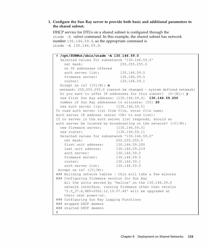
1. Configure the Sun Ray server to provide both basic and additional parameters tothe shared subnet.
DHCP service for DTUs on a shared subnet is configured through theutadm -A subnet command. In this example, the shared subnet has networknumber 130.146.59.0, so the appropriate command isutadm -A 130.146.59.0:
# /opt/SUNWut/sbin/utadm -A 130.146.59.0 Selected values for subnetwork "130.146.59.0" net mask: 255.255.255.0 no IP addresses offered auth server list: 130.146.59.5 firmware server: 130.146.59.5 router: 130.146.59.1 Accept as is? ([Y]/N): nnetmask: 255.255.255.0 (cannot be changed - system defined netmask)
Do you want to offer IP addresses for this subnet? (Y/[N]): y new first Sun Ray address: [130.146.59.4] 130.146.59.200 number of Sun Ray addresses to allocate: [55] 20 new auth server list: [130.146.59.5]To read auth server list from file, enter file name:Auth server IP address (enter <CR> to end list):If no server in the auth server list responds, should anauth server be located by broadcasting on the network? ([Y]/N): new firmware server: [130.146.59.5] new router: [130.146.59.1] Selected values for subnetwork "130.146.59.0" net mask: 255.255.255.0 first unit address: 130.146.59.200 last unit address: 130.146.59.219 auth server: 130.146.59.5 firmware server: 130.146.59.5 router: 130.146.59.1 auth server list: 130.146.59.5 Accept as is? ([Y]/N):### Building network tables - this will take a few minutes### Configuring firmware version for Sun Ray All the units served by "helios" on the 130.146.59.0 network interface, running firmware other than version "2.0_37.b,REV=2002.12.19.07.46" will be upgraded at their next power-on.### Configuring Sun Ray Logging Functions### stopped DHCP daemon### started DHCP daemon#
Chapter 8 Deployment on Shared Networks 115

s.
The default values initially suggested by utadm were not appropriate. Specifically,this server would not have offered any IP addresses on the 130.146.59.0 subnetbecause utadm assumes that basic networking parameters, including IP addresses,are provided by some external DHCP service when the DTU is located on a sharedsubnet. In this example, however, the Sun Ray server is required to provide IPaddresses, so the administrator replied n to the first Accept as is? prompt andwas given the opportunity to provide alternative values for the various parameters.Twenty IP addresses, starting at 130.146.59.200, were made available forallocation to DHCP clients on this subnet.
2. Restart Sun Ray services on the Sun Ray server.
Once the utadm command has completed, issue a utrestart command to fullyactivate Sun Ray services on the shared subnet:
Directly-Connected Shared Subnet: Example 2
In this example, the answers to the three pre-deployment questions are:
1. From which DHCP server will DTUs on this subnet get their basic IP networkingparameters?
From an external DHCP service.
2. From which DHCP server will DTUs on this subnet get additional configurationparameters to support features such as firmware download?
The DTUs will not be supplied with additional parameters.
3. How will DTUs on this subnet locate their Sun Ray server?
By using the local subnet broadcast discovery mechanism.
In this example, the Sun Ray server does not participate in DTU initialization at all.Why, then, are configuration steps required on the Sun Ray server? The Sun Rayserver responds by default only to DTUs located on directly connected dedicatedinterconnects. It responds to DTUs on shared subnets only if the utadm -L oncommand has been executed. Running the utadm -A subnet command to activateDHCP on the Sun Ray server for a shared subnet, as in this example, implicitlyexecutes utadm -L on. If utadm -A subnet has not been run, the administratormust run utadm -L on manually to allow the server to offer sessions to DTUs onthe shared subnet.
# /opt/SUNWut/sbin/utrestartResetting servers... messages will be logged to /var/opt/SUNWut/log/message
116 Sun Ray Server Software 3.1 Administrator’s Guide • September 2005

1. Configure the external DHCP service.
Determining how to configure the external DHCP infrastructure to provide basicnetworking parameters to the DTUs on this subnet is beyond the scope of thisdocument. Bear in mind:
■ If the external DHCP service does not have its own direct connection to thissubnet, the administrator must configure a DHCP Relay Agent to deliver DHCPtraffic on this subnet to the external DHCP service. The most likely location forsuch a Relay Agent would be on a router in this subnet, in this case the routernamed r22-59 in FIGURE 8-2. For a brief introduction to this topic refer to “DHCPRelay Agent” on page 106.
■ An existing external DHCP service may need to have its IP address allocation forthis subnet increased in order to support the new DTUs. (This applies wheneveradditional DHCP clients are placed on a subnet.) It might also be desirable toreduce the lease time of addresses on this subnet so that addresses becomeeligible for reuse quickly.
2. Configure the Sun Ray server to accept DTU connections from shared subnets.
Run utadm -L on:
3. Restart Sun Ray services on the Sun Ray server.
Once the utadm command has completed, issue a utrestart command to fullyactivate Sun Ray services on the shared subnet::
Deployment on a Remote SubnetSubnets C and D in FIGURE 8-2 are remote shared subnets.
Subnet C uses IP addresses in the range 130.146.22.0/24. Subnet D uses IPaddresses in the range 130.146.71.0/24. The Sun Ray server named helios has nodirect attachment to either of these subnets; it is this characteristic that defines themas remote. The answers to the three pre-deployment questions are:
1. From which DHCP server will DTUs on this subnet get their basic IP networkingparameters?
# /opt/SUNWut/sbin/utadm -L on### Turning on Sun Ray LAN connectionNOTE: utrestart must be run before LAN connections will be allowed
# /opt/SUNWut/sbin/utrestartResetting servers... messages will be logged to /var/opt/SUNWut/log/messages.
Chapter 8 Deployment on Shared Networks 117

In a shared subnet scenario, the administrator must choose whether a DHCP service onthe Sun Ray server or some external DHCP service will provide the DTU with basicnetwork parameters.
If the enterprise already has a DHCP infrastructure that covers this subnet, it probablysupplies basic network parameters. If no such infrastructure exists, configure the Sun Rayserver to provide basic network parameters.
2. From which DHCP server will DTUs on this subnet get additional configurationparameters to support features such as firmware download?
The administrator must choose whether additional configuration parameters will besupplied to the DTU, and if so whether they will be supplied by a DHCP service on theSun Ray server or by some external DHCP service.
Administrators of an established DHCP infrastructure may be unable or unwilling toreconfigure it to provide additional Sun Ray configuration parameters, so it is usuallymore convenient to have the Sun Ray server provide them.
Even when the established infrastructure is capable of delivering the additionalparameters, it may be desirable to have the Sun Ray server provide them. This enables youto use Sun Ray Server Software commands to manage the values of the additionalconfiguration parameters, when those values need to be changed in response to softwareupgrades or patch installations on the Sun Ray server. For instance, a patch that deliversnew DTU firmware could automatically update the firmware version string delivered tothe DTU. However, if the firmware version parameter is supplied by some external DHCPservice, an administrator must manually edit the firmware version parameter string inthe external DHCP configuration rules to reflect the new firmware version delivered bythe patch. This kind of activity is time-consuming and error-prone as well as unnecessary.
3. How will DTUs on this subnet locate their Sun Ray server?
Use one of the optional additional configuration parameters to report the location of theSun Ray server to the DTU. If additional configuration parameters are not supplied to theDTU at all, the DTU cannot locate a Sun Ray server, so it tries to discover the location ofa Sun Ray server by using a broadcast-based mechanism. However, the DTUs broadcastpackets propagate only on the local subnet; they cannot reach a Sun Ray server located ona remote subnet, and cannot establish contact.
The next two examples illustrate representative remote shared subnetconfigurations. In the first example, an external DHCP service provides basicnetworking parameters, and the Sun Ray server provides additional parameters.This is by far the most likely configuration for a Sun Ray deployment in anenterprise that has an established DHCP infrastructure.
In the second example, basic networking parameters and a bare minimum ofadditional parameters—just enough to enable the DTU to contact a Sun Rayserver—are supplied by an external DHCP. In this case, it is the DHCP service in aCisco router. This scenario is less than ideal.
118 Sun Ray Server Software 3.1 Administrator’s Guide • September 2005

No firmware parameters are delivered to the DTU, so it cannot download newfirmware. The administrator must make some other arrangement to provide theDTU with new firmware, for instance, by rotating it off this subnet periodically ontoan interconnect or onto some other shared subnet where a full set of additionalconfiguration parameters is offered.
Note – For examples of shared subnet deployments in which both basic networkingparameters and additional parameters are delivered by the Sun Ray server and basicnetworking parameters are supplied by an external DHCP service (with noadditional DTU parameters provided), see “Directly-Connected Shared Subnet” onpage 108.
Remote Shared Subnet: Example 1
In this example, in which DTUs are deployed on subnet C in FIGURE 8-2, the answersto the three pre-deployment questions are:
1. From which DHCP server will DTUs on this subnet get their basic IP networkingparameters?
From an external DHCP service.
2. From which DHCP server will DTUs on this subnet get additional configurationparameters to support features such as firmware download?
From the Sun Ray server.
3. How will DTUs on this subnet locate their Sun Ray server?
The DTUs will be informed of the location of the Sun Ray server through an additionalconfiguration parameter delivered in Step 2.
Use the utadm -A subnet command as follows to configure DHCP service forDTUs on a shared subnet.
1. Configure the external DHCP service.
Determining how to configure the external DHCP infrastructure to provide basicnetworking parameters to the DTUs on this subnet is beyond the scope of thisdocument. Bear in mind:
■ If the external DHCP service does not have its own direct connection to thissubnet, the administrator must configure a DHCP Relay Agent to deliver DHCPtraffic on this subnet to the external DHCP service. The most likely location forsuch a Relay Agent would be on a router in this subnet, in this case the routernamed r22-59 in FIGURE 8-2. For a brief introduction to this topic refer to “DHCPRelay Agent” on page 106.
Chapter 8 Deployment on Shared Networks 119

■ An existing external DHCP service may need to have its IP address allocationincreased for this subnet to support the new DTUs. (This applies wheneveradditional DHCP clients are placed on a subnet.) It might also be desirable toreduce the lease time of addresses on this subnet so that addresses becomeeligible for re-use quickly.
2. Arrange to deliver DHCP traffic to the Sun Ray server.
Because the Sun Ray server does not have its own direct connection to this subnet,the administrator must configure a DHCP Relay Agent to deliver the subnet’s DHCPtraffic to the Sun Ray server. The most likely location for such a Relay Agent wouldbe on a router in this subnet, in this case the router named r22-59 in FIGURE 8-2. Fora brief introduction to this topic refer to “DHCP Relay Agent” on page 106.
If r22-59 is running the Cisco IOS, the ip helper-address command can beused to activate its DHCP Relay Agent to relay DHCP broadcasts from its 10/100Ethernet port number 4 to the Sun Ray server at 130.146.59.5.
If the external DHCP service also lacks a connection to this subnet, configure aDHCP Relay Agent to forward requests from the DTU to:
■ The external DHCP service (so that the DTU can obtain basic networkingparameters)
■ The DHCP service on the Sun Ray server (so that the DTU can obtain additionalparameters)
The Cisco IOS ip helper-address command accepts multiple relay destinationaddresses, so if, for instance, the external DHCP service could be contacted at130.146.59.2 on subnet B in FIGURE 8-2, the appropriate sequence would be:
Note – Details of the IOS interaction vary according to the specific release of IOS,the model of the router, and the hardware installed in the router.
r22-59> interface fastethernet 4r22-59> ip helper-address 130.146.59.5r22-59>
r22-59> interface fastethernet 4r22-59> ip helper-address 130.146.59.2 130.146.59.5r22-59>
120 Sun Ray Server Software 3.1 Administrator’s Guide • September 2005

3. Configure the Sun Ray server to provide additional parameters to the sharedsubnet.
Use the utadm -A subnet command to configure DHCP service for DTUs on ashared subnet. In this example, the shared subnet has network number130.146.22.0, so the appropriate command is utadm -A 130.146.22.0.
In this example, the default values initially suggested by utadm were notappropriate. Specifically, the default router address to be used by DTUs on thissubnet was not correct because utadm guesses that the address of the default routerfor any shared subnet will have a host part equal to 1. This was a great guess for thedirectly-connected subnet B in FIGURE 8-2, but it is not correct for subnet C.
# /opt/SUNWut/sbin/utadm -A 130.146.22.0 Selected values for subnetwork "130.146.22.0" net mask: 255.255.255.0 no IP addresses offered auth server list: 130.146.59.5 firmware server: 130.146.59.5 router: 130.146.22.1Accept as is? ([Y]/N): nnew netmask:[255.255.255.0]Do you want to offer IP addresses for this subnet? (Y/[N]):new auth server list: [130.146.59.5]To read auth server list from file, enter file name:Auth server IP address (enter <CR> to end list):If no server in the auth server list responds, should anauth server be located by broadcasting on the network? ([Y]/N):new firmware server: [130.146.59.5]new router: [130.146.22.1] 130.146.22.6Selected values for subnetwork "130.146.59.0" net mask: 255.255.255.0 no IP addresses offered auth server list: 130.146.59.5 firmware server: 130.146.59.5 router: 130.146.22.6Accept as is? ([Y]/N):### Building network tables - this will take a few minutes### Configuring firmware version for Sun RayAll the units served by "helios" on the 130.146.22.0network interface, running firmware other than version"2.0_37.b,REV=2002.12.19.07.46" will be upgraded at theirnext power-on.### Configuring Sun Ray Logging Functions### stopped DHCP daemon### started DHCP daemon#
Chapter 8 Deployment on Shared Networks 121

.
The appropriate router address for DTUs on this subnet is 130.146.22.6 (port 4of router r22-59), so the administrator replied n to the first Accept as is?prompt and was given the opportunity to provide alternative values for the variousparameters.
4. Restart Sun Ray services on the Sun Ray server.
Once the utadm command has completed, issue a utrestart command to fullyactivate Sun Ray services on the shared subnet:
Remote Shared Subnet: Example 2
In this example, deploying DTUs on subnet D in FIGURE 8-2, the answers to the threepre-deployment questions are:
1. From which DHCP server will DTUs on this subnet get their basic IP networkingparameters?
From an external DHCP service.
2. From which DHCP server will DTUs on this subnet get additional configurationparameters to support features such as firmware download?
The DTUs will not be supplied with the additional parameters required to supportfirmware download or to activate other advanced DTU features.
3. How will DTUs on this subnet locate their Sun Ray server?
The external DHCP service will supply a single additional parameter to inform the DTUof the location of a Sun Ray server.
In this example, the Sun Ray server does not participate in DTU initialization at all.Why, then, are configuration steps required on the Sun Ray server? The Sun Rayserver responds by default only to DTUs located on directly connected dedicatedinterconnects. It responds to DTUs on shared subnets only if the utadm -L oncommand has been executed. Running the utadm -A subnet command to activateDHCP on the Sun Ray server for a shared subnet, as in this example, implicitlyexecutes utadm -L on. If utadm -A subnet has not been run, the administratormust run utadm -L on manually to allow the server to offer sessions to DTUs onthe shared subnet.
1. Configure the external DHCP service.
Determining how to configure the external DHCP infrastructure to provide basicnetworking parameters to the DTUs on this subnet is beyond the scope of thisdocument. However, for this example, assume that DHCP service is provided by
# /opt/SUNWut/sbin/utrestartResetting servers... messages will be logged to /var/opt/SUNWut/log/messages
122 Sun Ray Server Software 3.1 Administrator’s Guide • September 2005

Cisco IOS-based router r22-71 in FIGURE 8-2, attached to the 130.146.71.0 subnetthrough its 10/100 Ethernet port 3. This router can be configured to provide basicnetworking parameters and the location of a Sun Ray server as follows:
Note – Details of the IOS interaction vary according to the specific release of IOS,the model of router and the hardware installed in the router.
DHCP option 49, the standard option of the X Window Display Manager, identifies130.146.59.5 as the address of a Sun Ray server. In the absence of AltAuth andAuth-Srvr vendor-specific options, the DTU tries to find a Sun Ray server bybroadcasting on the local subnet. If the broadcasts evoke no response, the DTU usesthe address supplied in t option of the X Window Display Manager—provided that theDTU contains firmware at Sun Ray Server Software 2.0 patch level 114880-01 or later.
Note – This is an unorthodox use of the option of the X Window Display Manager,but in a remote subnet deployment where vendor-specific options can not bedelivered, it may be the only way of putting a DTU in touch with a server.
2. Configure the Sun Ray server to accept DTU connections from shared subnets byrunning utadm -L on.
r22-71> interface fastethernet 3r22-71> ip dhcp excluded-address 130.146.71.1 130.146.71.15r22-71> ip dhcp pool CLIENTr22-71/dhcp> import allr22-71/dhcp> network 130.146.71.0 255.255.255.0r22-71/dhcp> default-router 130.146.71.4r22-71/dhcp> option 49 ip 130.146.59.5r22-71/dhcp> lease 0 2r22-71/dhcp> ^Zr22-71>
# /opt/SUNWut/sbin/utadm -L on### Turning on Sun Ray LAN connectionNOTE: utrestart must be run before LAN connections will be allowed#
Chapter 8 Deployment on Shared Networks 123

3. Restart Sun Ray services on the Sun Ray server.
Once the utadm command has completed, issue a utrestart command to fullyactivate Sun Ray services on the shared subnet:
TABLE 8-2 lists the vendor-specific DHCP options that Sun Ray defines and uses.
The DTU can perform its basic functions even if none of these options are deliveredduring initialization, but some advanced DTU features do not become active unlesscertain options are delivered to the DTU. In particular:
■ AltAuth and AuthSrvr indicate the IP addresses of Sun Ray servers. Addressesin the AltAuth list are tried in order until a connection is established. Currentfirmware ignores AuthSrvr if AltAuth is provided, but it is good practicealways to specify AuthSrvr for the benefit of old (pre Sun Ray Server Software1.3) firmware, which does not understand the AltAuth option. If neither of these
# /opt/SUNWut/sbin/utrestartResetting servers... messages will be logged to/var/opt/SUNWut/log/messages.#
TABLE 8-2 Vendor-specific DHCP Options
Parameter Name Client ClassOptionCode Data Type
Optional/Mandatory Granularity
MaxCount Comments
AltAuth SUNW.NewT.SUNW 35 IP Optional 1 0 List of Sun Ray server IPaddresses
AuthSrvr SUNW.NewT.SUNW 21 IP Mandatory 1 1 Single Sun Ray server IPaddresses
AuthPort SUNW.NewT.SUNW 22 NUMBER Optional 2 1 Sun Ray server portNewTVer SUNW.NewT.SUNW 23 ASCII Optional 1 0 Desired firmware versionFWSrvr SUNW.NewT.SUNW 31 IP Optional 1 1 Firmware TFTP server IP
addressBarrierLevel SUNW.NewT.SUNW 36 NUMBER Mandatory 4 1 Firmware Download:
barrier levelLogHost SUNW.NewT.SUNW 24 IP Optional 1 1 Syslog server IP addressLogKern SUNW.NewT.SUNW 25 NUMBER Optional 1 1 Log level for kernelLogNet SUNW.NewT.SUNW 26 NUMBER Optional 1 1 Log level for networkLogUSB SUNW.NewT.SUNW 27 NUMBER Optional 1 1 Log level for USBLogVid SUNW.NewT.SUNW 28 NUMBER Optional 1 1 Log level for videoLogAppl SUNW.NewT.SUNW 28 NUMBER Optional 1 1 Sun Rat server interface
nameIntf SUNW.NewT.SUN 29 ASCII Optional 1 0 Sun Ray server interface
nameNewTBW 30 NUMBER Optional 4 1 Bandwidth capNewTDispIndx SUNW.NewT.SUNW 32 NUMBER Optional 4 1 Obsolete. Do not use.NewTFlags SUNW.NewT.SUNW 34 NUMBER Optional 4 1 Obsolete. Do not use.
124 Sun Ray Server Software 3.1 Administrator’s Guide • September 2005

options is supplied, the DTU tries to locate a Sun Ray server by sendingbroadcasts on the local subnet. If the DTU contains firmware at Sun Ray ServerSoftware 2.0 patch level 114880-01 or later, it resorts to trying to contact a Sun Rayserver at the address supplied in the option of the X Window Display Manager ifthat option has been provided.
■ NewTVer and FWSrvr must both be provided in order for the DTU to attempt afirmware download. NewTVer contains the name of the firmware version that theDTU should use. If this name does not match the name of the firmware versionthat the DTU is actually running, the DTU tries to download the desired firmwarefrom a TFTP server at the address given by FWSrvr.
■ LogHost must be specified in order for the DTU to report messages through thesyslog protocol. Reporting thresholds for major DTU subsystems are controlledby the LogKern, LogNet, LogUSB, LogVid, and LogAppl options.
Note – The message formats, contents, and thresholds are intended for use only byservice personnel and are not documented intentionally.
The DHCP Client Class name for all Sun Ray vendor-specific options isSUNW.NewT.SUNW. The DTU cites this name in DHCP requests so that the server canrespond with the appropriate set of vendor-specific options. This mechanismguarantees that the DTU is not given vendor options defined for some other type ofequipment and that other equipment is not given options that are meaningful onlyto the DTU.
Chapter 8 Deployment on Shared Networks 125

Network Performance RequirementsThis section describes the minimal network infrastructure needed to support a SunRay implementation.
Packet LossBefore version 2.0, Sun Ray Server Software was intolerant of packet losses, so it wasrecommended that packet loss not exceed 0.1 percent over any extended period.However, because this is often an impractical requirement in local area (LAN) andwide area (WAN) network Sun Ray deployments, the Sun Ray Server Software hasbeen made much more robust in the face of packet loss. The first version of thisimproved software was released with the first 2.0 patch, with additionalimprovements in releases supporting low-bandwidth WAN Sun Ray deployments.
In earlier versions, the server tried to avoid packet loss by severely limiting its use ofavailable bandwidth whenever it encountered packet loss. Because random lossesare inevitable in a non-dedicated LAN or WAN network environment, this approachput unnecessary limits on performance.
Sun Ray Server Software has always had the capability to detect and recover quicklyfrom such losses, so avoiding them was a matter of policy more than necessity. Thenew software is less timid and avoids operating at bandwidth levels that createpacket losses. Instead, it tries to send data at the highest possible rate that it canwithout incurring large losses. By design, it sometimes sends data at a rate that istoo great for the capacity of the connection between the server and the client, andthus discovers what that capacity is. With very high demand, sustained packet lossesof up to 10 percent may sometimes be seen, but the software continues to operateand update the contents of the screen correctly nevertheless.
LatencyNetwork latency between any Sun Ray client and its server is an importantdeterminant of the quality of the user experience. The lower the latency, the better;latencies under 50 milliseconds for round trip delay are preferred. However, likefamiliar network protocols such as TCP, the Sun Ray DTU does tolerate higherlatencies, but with degraded performance. Latencies up to 150 milliseconds provideusable, if somewhat sluggish, performance.
126 Sun Ray Server Software 3.1 Administrator’s Guide • September 2005

Out-of-Order PacketsDTUs that contain Sun Ray Server Software 2.0 firmware or later can tolerate smalloccurrences of out-of-order packet delivery, such as might be experienced on anInternet or wide-area intranet connection. Current Sun Ray firmware maintains areordering queue that restores the correct order to packets when they are receivedout of order. In releases prior to Sun Ray Server Software 2.0, out-of-order packetswere simply discarded.
Troubleshooting Tools
utcapture
The utcapture utility connects to the Sun Ray Authentication Manager and reportspacket loss statistics and round-trip latency timings for each DTU connected to thisserver. See the utcapture man page to learn more about this command.
utquery
The utquery command interrogates a DTU and displays the DTUs initializationparameters along with the IP addresses of the DHCP services that supplied thoseparameters. It can be helpful in determining whether a DTU was able to obtain theparameters that were expected in a particular deployment and in determiningspecific DHCP servers that contributed to the DTUs initialization. See the utqueryman page to learn more about this command.
OSD IconsSun Ray DTU on-screen display (OSD) icons contain information that can help theadministrator understand and debug network configuration problems. The amountof information encoded into the icons has been significantly expanded in thefirmware delivered with Sun Ray Server Software. The icon structure andprogression are described in detail in Appendix .
Chapter 8 Deployment on Shared Networks 127

Encapsulated OptionsFor each parameter name, there is a vendor ID, an option code, an option type, andan indication as to whether the parameter is mandatory.
Vendor-specific options are delivered through encapsulated options in DHCP.Encapsulated options are somewhat more complicated, as illustrated in thefollowing DHCPINFORM response, or DHCPACK, which shows the taxonomy ofthe bytes in the vendor-specific information portion.
Note – In this description, hexadecimal values are preceded by 0x and followed bytheir decimal value, after an = sign, as in 0x2b=43.
■ The first byte is the option code.■ The next byte represents the encapsulated option length, that is, the number of
bytes that make up the option value.■ The next one or more bytes make up the multi-byte option value.
The option value is followed by another encapsulated option code, and so on.
The example begins with 0x2b=43, the DHCP option for vendor-specificinformation. It has a length of 0x4a=74 bytes, which is the total number of bytesthat follow. These bytes contain the encapsulated vendor options.
The remainder of the example represents the value of the vendor-specificinformation options. The first byte contains the first encapsulated option, whosevalue is 0x17=23, and the NewTVer option, whose value type is ASCII. The nextbyte is 0x1d=29, which is the length of the NewTVer string. These options arefollowed by 29 bytes that represent the string itself.
The ASCII interpretation at the right of the DHCPACK, is2.0_19.c,REV=2002.09.06.15.54. This is the end of the first encapsulatedoption. The next byte is the beginning of the next option, Intf, represented by0x21=33. The next byte, the length, is 0x04=4, and the next four bytes are the ASCIIvalue hme0. That’s the end of the second encapsulated option.
2b 4a 17 1d 32 2e 30 .......: .+J..2.0
0140 5f 31 39 2e 63 2c 52 45 56 3d 32 30 30 32 2e 30 _19.c,RE V=2002.0
0150 39 2e 30 36 2e 31 35 2e 35 34 21 04 68 6d 65 30 9.06.15. 54!.hme0
0160 1f 04 81 92 3a 88 15 04 81 92 3a 88 1d 01 06 1c ....:... ..:.....
0170 01 06 1b 01 06 1a 01 06 19 01 06 18 04 81 92 3a ........ .......:
0180 88 16 02 1b 61
128 Sun Ray Server Software 3.1 Administrator’s Guide • September 2005

The next byte is 0x1f=31, which represents the FWSrvr parameter, whose functionis to indicate the IP address of the firmware TFTP server. The next byte is the length,4, which is always be true for an IP address. The hexadecimal value is0x81 0x92 0x3a 0x88, which corresponds to the IP address 129.146.58.136.
Remote ConfigurationYou can simplify the DHCP configuration of Sun Ray DTUs at remote sites by usingthe X Window System Display Manager option to supply a list of available Sun Rayservers. This eliminates the need for Sun Ray vendor options as well as the need toforward DHCPINFORM requests to a Sun Ray server.
A sample DHCP configuration for a Cisco IOS-based router is shown below:
Option 49, the X Window System Display Manager option, lists IP addresses10.6.129.67 and 129.146.58.136 as Sun Ray servers. The Sun Ray DTU tries toconnect to those servers when it receives a DHCP response from the router. Option26 sets the Maximum Transfer Unit (MTU) for the Sun Ray connections, in this case1366 bytes rather than the default Ethernet MTU of 1500 bytes. This is necessary toallow space for the IPSec headers to implement a VPN connection.
DHCP service, either directly from an ISP or from a home firewall, is also required,to give the router its IP address behind the firewall.
The router’s WAN port either plugs directly into the DSL/Cable modem4 or into thehome firewall/gateway. The Sun Ray DTU then plugs into one of the four LANports on the router. If the router has been configured to supply DHCP parameters tothe Sun Ray DTU, it will tell it to try to connect to the appropriate Sun Ray server.
The router should bring up a VPN tunnel when it is plugged in; it should always beon. Each router should be programmed with a username based on an employee’s IDand a random password and connected to the VPN gateway. The VPN gateway
ip dhcp excluded-address 129.149.244.161
ip dhcp pool CLIENT
import all network 129.149.244.160 255.255.255.248
default-router 129.149.244.161
option 26 hex 0556
option 49 ip 10.6.129.67 129.146.58.136
lease 0 2
4. IA VPN router plugged directly into the DSL or Cable modem can be connected only to a Sun Ray DTU.
Chapter 8 Deployment on Shared Networks 129

should be configured to allow only Sun Ray traffic to pass, and only to a limitednumber of hosts, so that users cannot connect anything else to the LAN side of therouter and then connect into the corporate network. However, users may connectmore than one Sun Ray DTU.
Enhancements to Firmware Downloadand Configuration SupportImprovements in the firmware make it easier to bring up a set of Sun Ray DTUswith nothing more than generic DHCP parameters.
■ The burden of defining the server list can be shifted to the Domain Name Service(DNS).
■ Firmware management can be shifted completely to TFTP.■ If sunray-config-servers and sunray-servers are defined appropriately
by the DNS serving a set of remote Sun Rays DTUs, no extra DHCP parametersare required other than basic network information.
The enhancements include:
1. Incorporation of a DNS client in the firmware, which allows many values to benames rather than IP addresses.
2. Support for DHCP option 66 (TFTP server name) as an alternative to the FWSrvrvendor option. This can resolve to a list of IP addresses, one of which is chosenrandomly.
3. A new firmware maintenance mechanism creates *.parms files in /tftpboot(one for each model type), which are read in lieu of using the NewTVer DHCPvendor option. Thus, remote firmware upgrades are possible without DHCPaccess to the NewTVer value. The *.parms files contain the version, hardwarerevision, and barrier levels, eliminating unnecessary file reads in cases where thebarrier would have prevented writing the firmware to flash. For details onoptions that can be used to configure the .parms files, see utfwadm(8).
4. Use of a default DNS name for the firmware server when neither option 66 norFWSrvr is given. The name chosen is sunray-config-servers. Defining it inDNS gives a way to provide the firmware server address without DHCP options,just DNS servers and domain name.
5. Inclusion of servers=<server name list> and select=<inorder|random> in the*.parms files to allow:
■ specification of a list of server names■ specification of whether the names should be used in order, or at random
130 Sun Ray Server Software 3.1 Administrator’s Guide • September 2005

If a name resolves to multiple addresses, then an IP address is chosen accordingto the select keyword.
6. When neither a server list nor an AltAuth list is given, the default namesunray-servers is looked up in DNS, and the list of IP addresses is used inplace of the AltAuth list.‘
Chapter 8 Deployment on Shared Networks 131

132 Sun Ray Server Software 3.1 Administrator’s Guide • September 2005
CHAPTER 9
Multihead Administration
The multihead feature on Sun Ray™ DTUs enables users to control separateapplications on multiple screens, or heads, using a single keyboard and pointerdevice attached to the primary DTU. Users can also display and control a singleapplication, such as a spreadsheet, on multiple screens. System administrators createmultihead groups that may be accessed by users. A multihead group, consisting ofbetween two and 16 DTUs controlled by one keyboard and mouse, may becomposed of any mix of Sun Ray DTUs, such as Sun Ray 1, Sun Ray 100, Sun Ray150, and Sun Ray 170, for instance. Each DTU presents an X screen of the multiheadX display.
Note – For the multihead feature to function properly:1. You must be in administered mode; therefore, you must run utconfig before yourun utmhconfig and utmhadm.2. You must enable the multihead policy using either utpolicy or the Admin GUI.3. Always run utmhconfig from a Sun Ray DTU.
Note – Regional hotdesking is not enabled for multihead groups.
Multihead GroupsA multihead group is comprised of a set of associated Sun Ray DTUs controlled by aprimary DTU to which a keyboard and pointer device, such as a mouse, areconnected. This group, which can contain a maximum of 16 DTUs, is connected to asingle session.
133

Unless XINERAMA is enabled (see “XINERAMA” on page 139 for more details),sessions will have a separate CDE toolbar (with separate workspaces) per screen. Awindow cannot be moved between screens.
The primary DTU hosts the input devices, such as a keyboard and a pointer device,and the USB devices associated with the session. The remaining DTUs, called thesecondaries, provide the additional displays. All peripherals are attached to theprimary DTU, and the group is controlled from the primary DTU.
Multihead groups can be created easily by using a smart card to identify theterminals with the utmhconfig GUI utility.
Tip – For best results, run utmhconfig only from a DTU.
However, if you disconnect the secondary DTUs without deleting the multiheadgroup to which they belong, the screens are not displayed on the single primaryDTU. The primary DTU is still part of the multihead group, and the mouse seems toget lost when it goes to the disconnected secondary DTU. To recover from thissituation, you can either reconnect the missing DTU or delete the multihead groupusing the utmhconfig or utmhadm command, or you can delete the multiheadgroup, replace the missing DTU, and create a new multihead group thatincorporates the replacement DTU.
Multihead Screen ConfigurationA multihead group can have its screens arranged in various configurations. Forexample, a user can arrange a multihead group of four screens as two rows of twoscreens (2x2) or as a single row of four screens (4x1). By default, when a user logsinto a multihead group, the session uses the number of screens available; the layout,or geometry. of these displays is generated automatically. You can use the -R optionto utxconfig to manipulate the automatic geometry, as in the following examples:
● To override the automatic geometry, where geometry is expressed as columns xrows. type:
● To restore the automatic geometry on the next login:
% utxconfig -R geometry
% utxconfig -R auto
134 Sun Ray Server Software 3.1 Administrator’s Guide • September 2005

When the mouse pointer is moved past the edge between two screens, it moves fromone screen to the next. The geometry of the multihead group determines whichscreen is displayed at that point.
Screen dimensions for the multihead group are automatically set, by default, to thelargest supported by the primary DTU. The primary DTU is the one that controls theother DTUs in the group and to which all peripherals are attached.
To override the automatic sizing of screen dimensions, use the -r option toutxconfig:
● To override automatic sizing, where dimensions are expressed as width x height (forexample, 1280 x 1024):
● To restore automatic sizing behavior on the next login:
Note – If explicit screen dimensions are chosen, the user may experience panning orblack-band effects.
● To explicitly choose not to use multiple displays for a session, type:
Note – If the resolutions of the monitors differ, you may have problems withunwanted on-screen movement called panning, or large black bands around the visiblescreen area.
Multihead Screen DisplayWhen the multihead feature is used, a small window indicating the current sessionon each screen is displayed with the current screen highlighted for easyidentification. This window is automatically displayed for users during sessioncreation. For example, the display in “XINERAMA” on page 139 indicates that theuser is on the second screen of a three-screen display.
% utxconfig -r dimensions
% utxconfig -r auto
% utxconfig -m off
Chapter 9 Multihead Administration 135

FIGURE 9-1 The Multihead Screen Display
Multihead Administration ToolThe administration tool for the multihead feature displays the current multiheadgroups and enables you to create new groups.
▼ To Turn On Multihead Policy From the Command Line
● On the command-line interface, type:
This enables the multihead policy for the failover group and restarts Sun Ray ServerSoftware with the new policy on the local server without disrupting existingsessions.
Tip – Issue the utrestart command on every server in the failover group.
▼ To Turn On Multihead Policy Using the AdministrationTool
1. Bring up the Administration Tool by typing the following URL into yourbrowser’s location field:
2. Select Admin from the navigation menu on the left side of the tool.
3. Select Policy.
4. Next to Multihead feature enabled, click the Yes radio button.
5. Click the Apply button.
6. Under Admin in the lefthand menu, select Reset Services.
# /opt/SUNWut/sbin/utpolicy -a -m -g your_policy_flags# /opt/SUNWut/sbin/utrestart
http://hostname:1660
136 Sun Ray Server Software 3.1 Administrator’s Guide • September 2005

7. Click the Restart button.
This sets the multihead policy for all servers and restarts Sun Ray Server Softwareon all servers.
▼ To Create a New Multihead Group
1. On the command-line interface, type:
2. On the initial screen, click Create New Group.
FIGURE 9-2 Multihead Group List With Group Detail
The Create New Multiheaded Group pop-up dialog box is displayed. The number ofrows and the number of columns you enter are displayed as the group geometrywhen the group has been created.
FIGURE 9-3 Create New Multiheaded Group Pop-up Dialog Box
# /opt/SUNWut/sbin/utmhconfig
Chapter 9 Multihead Administration 137

3. Enter the information for the group.
Enter a name for the group and the number of rows and columns.
4. Click the Next button.
A third screen is displayed.
FIGURE 9-4 Setup Display for the New Multihead Group
5. Select the DTUs within the multihead group and insert a smart card in each SunRay DTU in turn to establish the order of the group.
The Finish button, which was previously grayed out, is now active.
FIGURE 9-5 Completed Multihead Group List With Active Finish Button
6. Click the Finish button.
138 Sun Ray Server Software 3.1 Administrator’s Guide • September 2005

7. Exit the session or disconnect by removing your card.
XINERAMAThe XINERAMA extension to X11creates one single large screen displayed acrossseveral monitors. With XINERAMA only one toolbar is displayed, and a windowcan be moved smoothly from one part of the screen to the next.
A single toolbar (and set of workspaces) manages the configured monitors. Awindow can span monitors, since they are still within the same screen. This includesthe CDE toolbar itself.
Tip – Because XINERAMA consumes a lot of CPU, memory and networkbandwidth, please set the shmsys:shminfo_shmmax parameter in the/etc/system file to at least LARGEST_NUMBER_OF_HEADS * width * height * 4 forreasonable performance.
Users enable or disable XINERAMA as part of their X preferences. The utxconfigcommand handles this on an individual token basis. The user must log off for this totake effect.
The XINERAMA feature is enabled using the following command:
The XINERAMA feature is disabled using the following command:
To enable as default for a single system or failover group, as superuser, type thefollowing command:
% /opt/SUNWut/bin/utxconfig -x on
% /opt/SUNWut/bin/utxconfig -x off
% utxconfig -a -x on
Chapter 9 Multihead Administration 139

Session GroupsIf you hot desk from a multihead group to a DTU that is not part of a multiheadgroup—that is, a DTU with a single head—all the screens created in the originalmultihead group can be viewed on the single screen or head by panning to eachscreen in turn. This is called screen flipping.
Authentication ManagerThe TerminalGroup policy module extends the Authentication Manager to supportmultihead groups. When a DTU connects to the Authentication Manager or a newsmart card is inserted, the TerminalGroup module queries its database to determinewhether the DTU is part of a multihead group and, if so, whether the DTU is aprimary or secondary DTU of that group. If it is not identified as part of a multiheadgroup, the DTU is treated normally.
This flow chart asks the following questions:
FIGURE 9-6 Authentication Manager Flowchart for the Primary DTU
Does the primarysession exist?
Creates a newsession
Redirects theDTU to theappropriateserver
Does the sessionexist on thecurrent server?
Connect to theexisting session
YES
YES
NO
NO
140 Sun Ray Server Software 3.1 Administrator’s Guide • September 2005

If the DTU is determined to be part of a multihead group and it is the multiheadgroup’s primary DTU, a normal session placement occurs. If a session does not existon the current server, but there is a preexisting session for the DTU or smart card onanother server in the failover group, the primary DTU will be redirected to thatserver. If there is no session on any server, the request for a session is directed to theleast-loaded server and a session is created there.
If a DTU is determined to be part of a multihead group and it is a multihead groupsecondary DTU, the TerminalGroup module determines if the multihead- groupprimary DTU is locally attached to a session. If it is, it tells the Session Manager toallow the secondary DTU to also attach to that session. If the primary DTU is notattached locally, the TerminalGroup module determines if the primary DTU isattached to another server in the failover group (if any), and if it is, it redirects thesecondary DTU to that server.
FIGURE 9-7 Authentication Manager Flowchart for the Secondary DTU
If the primary DTU is determined to not be attached to any server in the failovergroup at that moment, a “waiting for primary” icon is displayed on the DTU, andfurther activity is blocked on that DTU until the primary is discovered. Thesecondary DTU is redirected to the server to which the primary is attached.
Starts up a new “waiting”session and keeps checking tosee whether the primaryconnects
Redirect theDTU to theappropriateserver
Is the primaryDTU currentlyconnected to asession?
Does the sessionexist on the localserver?
Connect to theexisting session
NO
NO
YES
YES
Chapter 9 Multihead Administration 141

142 Sun Ray Server Software 3.1 Administrator’s Guide • September 2005

CHAPTER 10
Failover Groups
Sun Ray servers configured in a failover group provide users with a high level ofavailability when one of those servers becomes unavailable because of a network orsystem failure. This chapter describes how to configure failover groups.
For a discussion on how to utilize multiple failover groups to utilize regionalhotdesking, see “Hotdesking (Mobile Sessions)” on page 87.
This chapter covers these topics:
■ “Failover Group Overview” on page 144■ “Setting Up IP Addressing” on page 146■ “Group Manager” on page 151■ “Load Balancing” on page 153■ “Setting Up a Failover Group” on page 154■ “Viewing the Administration Status” on page 156■ “Viewing Failover Group Status” on page 156■ “Recovery Issues and Procedures” on page 158■ “Setting Up a Group Signature” on page 161■ “Taking Servers Offline” on page 161
143

Failover Group OverviewA failover group consists of two or more Sun Ray servers grouped together toprovide highly-available and scalable Sun Ray service for a population of Sun RayDTUs. Releases earlier than 2.0 supported DTUs available to the servers only on acommon, dedicated interconnect. Beginning with the 2.0 release, this capability wasexpanded to allow access across the LAN to either local or remote Sun Ray devices.However, there is still a requirement for the servers in a failover group to be able toreach one another, using multicast or broadcast, over at least one shared subnet.Servers in a group authenticate (or “trust”) one another using a common groupsignature. The group signature is a key used to sign messages sent between serversin the group; it must be configured to be identical on each server.
Failover groups that use more than one version of Sun Ray Server Software will beunable to use all the features provided in the latest releases. On the other hand, thefailover group can be a heterogeneous group of Sun servers.
When a dedicated interconnect is used, all servers in the failover group should haveaccess to, and be accessible by, all the Sun Ray DTUs on a given sub-net. The failoverenvironment supports the same interconnect topologies that are supported by asingle-server Sun Ray environment. However, switches should be multicast-enabled.
FIGURE 10-1 illustrates a typical Sun Ray failover group. For an example of aredundant failover group, see FIGURE 10-2.
FIGURE 10-1 Simple Failover Group
Sun Rayservers
Sun Rayinterconnect
Sun RayDTUs
Publicnetwork
hme0
hme0
hme0
hme1
hme1
hme1
102.23.16.47
102.23.16.48
102.23.16.49
192.168.128.1
192.168.128.2
192.168.128.3
192.168.128.10
192.168.128.55
192.168.128.11
192.168.128.32
192.168.128.54
192.168.128.33
Switch
sr47
sr48
sr49
P
S
S
144 Sun Ray Server Software 3.1 Administrator’s Guide • September 2005
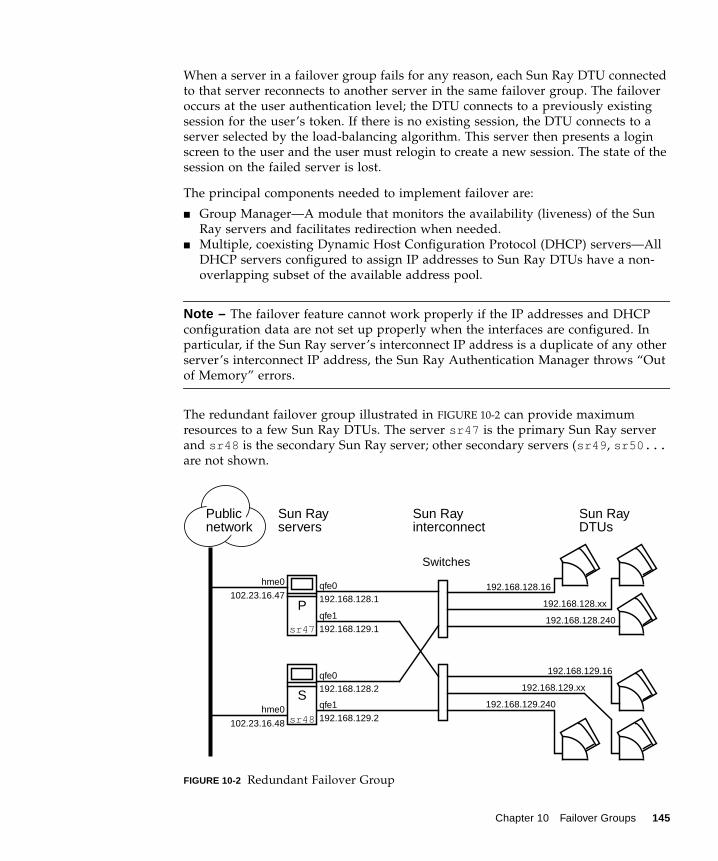
When a server in a failover group fails for any reason, each Sun Ray DTU connectedto that server reconnects to another server in the same failover group. The failoveroccurs at the user authentication level; the DTU connects to a previously existingsession for the user’s token. If there is no existing session, the DTU connects to aserver selected by the load-balancing algorithm. This server then presents a loginscreen to the user and the user must relogin to create a new session. The state of thesession on the failed server is lost.
The principal components needed to implement failover are:
■ Group Manager—A module that monitors the availability (liveness) of the SunRay servers and facilitates redirection when needed.
■ Multiple, coexisting Dynamic Host Configuration Protocol (DHCP) servers—AllDHCP servers configured to assign IP addresses to Sun Ray DTUs have a non-overlapping subset of the available address pool.
Note – The failover feature cannot work properly if the IP addresses and DHCPconfiguration data are not set up properly when the interfaces are configured. Inparticular, if the Sun Ray server’s interconnect IP address is a duplicate of any otherserver’s interconnect IP address, the Sun Ray Authentication Manager throws “Outof Memory” errors.
The redundant failover group illustrated in FIGURE 10-2 can provide maximumresources to a few Sun Ray DTUs. The server sr47 is the primary Sun Ray serverand sr48 is the secondary Sun Ray server; other secondary servers (sr49, sr50...are not shown.
FIGURE 10-2 Redundant Failover Group
qfe0192.168.128.1
qfe1192.168.129.2
qfe0192.168.128.2
qfe1192.168.129.1
Sun Rayservers
Sun Rayinterconnect
Sun RayDTUs
Publicnetwork
hme0
102.23.16.47
102.23.16.48
192.168.128.16
192.168.129.240
192.168.128.xx
192.168.128.240
192.168.129.xx
192.168.129.16
sr47
sr48
Switches
P
Shme0
Chapter 10 Failover Groups 145

Setting Up IP AddressingThe utadm command assists you in setting up a DHCP server. The default DHCPsetup configures each interface for 225 hosts and uses private network addresses forthe Sun Ray interconnect. For more information on using the utadm command, seethe man page for utadm.
Before setting up IP addressing, you must decide upon an addressing scheme. Thefollowing examples discuss setting up class C and class B addresses.
Setting Up Server and Client AddressesThe loss of a server usually implies the loss of its DHCP service and its allocation ofIP addresses. Therefore, more DHCP addresses must be available from the addresspool than there are Sun Ray DTUs. Consider the situation of 5 servers and 100 DTUs.If one of the servers fails, the remaining DHCP servers must have enough availableaddresses so that all “orphaned” DTUs get a new working address.
TABLE 10-1 describes how to configure five servers for 100 DTUs, accommodating thefailure of two servers (class C) or four servers (class B).
TABLE 10-1 Configuring Five Servers for 100 DTUs
Class C (2 Servers Fail) Class B (4 Servers Fail)
ServersInterfaceAddress DTU Address Range
InterfaceAddress DTU Address Range
serverA 192.168.128.1 192.168.128.16 to192.168.128.49
192.168.128.1 192.168.128.16 to192.168.128.116
serverB 192.168.128.2 192.168.128.50 to192.168.128.83
192.168.129.1 192.168.129.16 to192.168.129.116
serverC 192.168.128.3 192.168.128.84 to192.168.128.117
192.168.130.1 192.168.130.16 to192.168.130.116
serverD 192.168.128.4 192.168.128.118 to192.168.128.151
192.168.131.1 192.168.131.16 to192.168.131.116
serverE 192.168.128.5 192.168.128.152 to192.168.128.185
192.168.132.1 192.168.132.16 to192.168.132.116
146 Sun Ray Server Software 3.1 Administrator’s Guide • September 2005
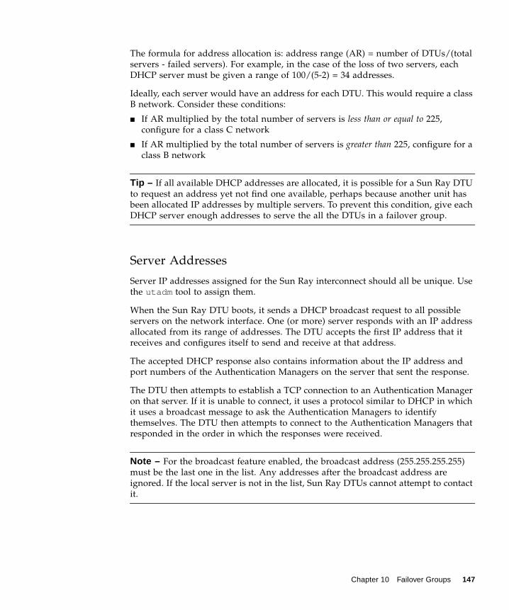
The formula for address allocation is: address range (AR) = number of DTUs/(totalservers - failed servers). For example, in the case of the loss of two servers, eachDHCP server must be given a range of 100/(5-2) = 34 addresses.
Ideally, each server would have an address for each DTU. This would require a classB network. Consider these conditions:
■ If AR multiplied by the total number of servers is less than or equal to 225,configure for a class C network
■ If AR multiplied by the total number of servers is greater than 225, configure for aclass B network
Tip – If all available DHCP addresses are allocated, it is possible for a Sun Ray DTUto request an address yet not find one available, perhaps because another unit hasbeen allocated IP addresses by multiple servers. To prevent this condition, give eachDHCP server enough addresses to serve the all the DTUs in a failover group.
Server Addresses
Server IP addresses assigned for the Sun Ray interconnect should all be unique. Usethe utadm tool to assign them.
When the Sun Ray DTU boots, it sends a DHCP broadcast request to all possibleservers on the network interface. One (or more) server responds with an IP addressallocated from its range of addresses. The DTU accepts the first IP address that itreceives and configures itself to send and receive at that address.
The accepted DHCP response also contains information about the IP address andport numbers of the Authentication Managers on the server that sent the response.
The DTU then attempts to establish a TCP connection to an Authentication Manageron that server. If it is unable to connect, it uses a protocol similar to DHCP in whichit uses a broadcast message to ask the Authentication Managers to identifythemselves. The DTU then attempts to connect to the Authentication Managers thatresponded in the order in which the responses were received.
Note – For the broadcast feature enabled, the broadcast address (255.255.255.255)must be the last one in the list. Any addresses after the broadcast address areignored. If the local server is not in the list, Sun Ray DTUs cannot attempt to contactit.
Chapter 10 Failover Groups 147

Once a TCP connection to an Authentication Manager has been established, the DTUpresents its token. The token is either a pseudo-token representing the individualDTU (its unique Ethernet address) or a smart card. The Session Manager then startsan X window/X server session and binds the token to that session.
The Authentication Manager then sends a query to all of the other AuthenticationManagers on the same subnet and asks for information about existing sessions forthe token. The other Authentication Managers respond, indicating whether there is asession for the token and the last time the token was connected to the session.
The requesting Authentication Manager selects the server with the latest connectiontime and redirects the DTU to that server. If no session is found for the token, therequesting Authentication Manager selects the server with the lightest load andredirects the token to that server. A new session is created for the token.
The Authentication Manager enables both implicit (smart card) and explicitswitching. For explicit switching, see “Group Manager” on page 151.
Configuring DHCPIn a large IP network, a DHCP server distributes the IP addresses and otherconfiguration information for interfaces on that network.
Coexistence of the Sun Ray Server With Other DHCP Servers
The Sun Ray DHCP server can coexist with DHCP servers on other subnets,provided you isolate the Sun Ray DHCP server from other DHCP traffic. Verify thatall routers on the network are configured not to relay DHCP requests. This is thedefault behavior for most routers.
Caution – If the IP addresses and DHCP configuration data are not set up correctlywhen the interfaces are configured, the failover feature cannot work properly. Inparticular, configuring the Sun Ray server’s interconnect IP address as a duplicate ofany other server’s interconnect IP address may cause the Sun Ray AuthenticationManager to throw “Out of Memory” errors.
Administering Other Clients
If the Sun Ray server has multiple interfaces, one of which is the Sun Rayinterconnect, the Sun Ray DHCP server should be able to manage both the Sun Rayinterconnect and the other interfaces without cross-interference.
148 Sun Ray Server Software 3.1 Administrator’s Guide • September 2005

▼ To Set Up IP Addressing on Multiple Servers Each WithOne Sun Ray Interface
1. Log in to the Sun Ray server as superuser and, open a shell window. Type:
where <interface_name> is the name of the Sun Ray network interface to beconfigured; for example, hme[0-9], qfe[0-9], or ge[0-9]. You must be logged onas superuser to run this command. The utadm script configures the interface (forexample, hme1) at the subnet (in this example, 128).
The script displays default values, such as the following:
The default values are the same for each server in a failover group. Certain valuesmust be changed to be unique to each server.
2. When you are asked to accept the default values, type n:
3. Change the second server’s IP address to a unique value, in this case 192.168.128.2:
4. Accept the default values for netmask, host name, and net name:
# /opt/SUNWut/sbin/utadm -a <interface_name>
Selected values for interface "hme1" host address: 192.168.128.1 net mask: 255.255.255.0 net address: 192.168.128.0 host name: serverB-hme1 net name: SunRay-hme1 first unit address: 192.168.128.16 last unit address: 192.168.128.240 auth server list: 192.168.128.1 firmware server: 192.168.128.1 router: 192.168.128.1
Accept as is? ([Y]/N): n
new host address: [192.168.128.1] 192.168.128.2
new netmask: [255.255.255.0]new host name: [serverB-hme1]
Chapter 10 Failover Groups 149

5. Change the DTU address ranges for the interconnect to unique values. Forexample:
6. Accept the default firmware server and router values:
The utadm script asks if you want to specify an authentication server list:
These servers are specified by a file containing a space-delimited list of server IPaddresses or by manually entering the server IP addresses.
The newly selected values for interface hme1 are displayed:
7. If these are correct, accept the new values:
8. Stop and restart the server and power cycle the DTUs to download the firmware.
Do you want to offer IP addresses for this interface? [Y/N]:new first Sun Ray address: [192.168.128.16] 192.168.128.50number of Sun Ray addresses to allocate: [205] 34
new firmware server: [192.168.128.2]new router: [192.168.128.2]
auth server list: 192.168.128.1To read auth server list from file, enter file name:Auth server IP address (enter <CR> to end list):If no server in the auth server list responds, should an authserver be located by broadcasting on the network? ([Y]/N):
Selected values for interface "hme1" host address: 192.168.128.2 net mask: 255.255.255.0 net address: 192.168.128.0 host name: serverB-hme1 net name: SunRay-hme1 first unit address: 192.168.128.50 last unit address: 192.168.128.83 auth server list: 192.168.128.1 firmware server: 192.168.128.2 router: 192.168.128.2
Accept as is? ([Y]/N): y
150 Sun Ray Server Software 3.1 Administrator’s Guide • September 2005

TABLE 10-2 lists the options available for the utadm command. For additionalinformation, see the utadm man page.
Group ManagerEvery server has a group manager module that monitors availability and facilitatesredirection. It is coupled with the Authentication Manager.
In setting policies, the Authentication Manager uses the selected authenticationmodules and decides what tokens are valid and which users have access.
Warning – The same policy must exist on every server in the failover group orundesirable results might occur.
Each Group Manager creates maps of the failover group topology by exchangingkeepalive messages among themselves. These keepalive messages are sent to awell-known UDP port (typically 7009) to all of the configured network interfaces.
TABLE 10-2 Available Options
Option Definition
-c Create a framework for the Sun Ray interconnect.
-r Remove all Sun Ray interconnects.
-A <subnetwork> Configure the subnetwork specified as a Sun Ray sub-network. Thisoption only configures the DHCP service to allocate IP addressand/or to provide Sun Ray parameters to Sun Ray clients. It alsowill automatically turn on support for LAN connections from ashared subnetwork.
-a <interface_name> Add <interface_name> as Sun Ray interconnect.
-D <subnetwork> Delete the subnetwork specified form the list of configured Sun Raysubnetworks.
-d <interface_name> Delete <interface_name> as Sun Ray interconnect.
-l Print the current configuration for all the Sun Ray subnetworks,including remote subnetworks.
-p Print the current configuration.
-f Take a server offline
-n Bring a server online
-x Print the current configuration in a machine-readable format
Chapter 10 Failover Groups 151

The keepalive message contains enough information for each Sun Ray server toconstruct a list of servers and the common subnets that each server can access. Inaddition, the group manager remembers the last time that a keepalive messagewas received from each server on each interface.
The keepalive message contains the following information about the server:
■ Server’s host name
■ Server’s primary IP address
■ Elapsed time since it was booted
■ IP information for every interface it can be reach
■ Machine information (number and speed of CPUs, configured RAM, and so on)
■ Load information (CPU and memory utilization, number of sessions, and so on)
Note – The last two items are used to facilitate load distribution. See “LoadBalancing” on page 153.
The information maintained by the Group Manager is used primarily for serverselection when a token is presented. The server and subnet information is used todetermine the servers to which a given DTU can connect. These servers are queriedabout sessions belonging to the token. Servers whose last keepalive message isolder than the timeout are deleted from the list, since either the network connectionor the server is probably down.
RedirectionIn addition to automatic redirection at authentication, you can use the utselectgraphical user interface (GUI) or utswitch command for manual redirection.
Note – The utselect GUI is the preferred method to use for server selection. Formore information, see the utselect man page.
Group Manager ConfigurationThe Authentication Manager configuration file, /etc/opt/SUNWut/auth.props,contains properties used by the Group Manager at runtime. The properties are:
■ gmport■ gmKeepAliveInterval■ enableGroupManager
152 Sun Ray Server Software 3.1 Administrator’s Guide • September 2005
■ enableLoadBalancing■ enableMulticast■ multicastTTL■ gmSignatureFile■ gmDebug
These properties have default values that are rarely changed. Only veryknowledgeable Sun support personnel should direct customers to change thesevalues to help tune or debug their systems. If any properties are changed, they mustbe changed for all servers in the failover group, since the auth.props file must bethe same on all servers in a failover group.
▼ To Restart the Authentication Manager
Property changes do not take effect until the Authentication Manager is restarted.
● As superuser, open a shell window and type:
The Authentication Manager is restarted.
Load BalancingAt the time of a server failure, the Group Manager on each remaining serverattempts to distribute the failed server’s sessions evenly among the remainingservers. The load balancing algorithm takes into account each server’s capacity(number and speed of its CPUs) and load so that larger or less heavily loadedservers host more sessions.
When the Group Manager receives a token from a Sun Ray DTU and finds that noserver owns an existing session for that token, it redirects the Sun Ray DTU to theserver in the group with the lightest load. It is possible that a Sun Ray DTU appearsto connect twice; once on the server that answered its DHCP request and a secondtime on a server that was less loaded than the first.
▼ To Turn Off the Load Balancing Feature
● In the auth.props file set:
# /opt/SUNWut/sbin/utrestart
enableLoadBalancing = false
Chapter 10 Failover Groups 153

Setting Up a Failover GroupA failover group is one in which two or more Sun Ray servers use a common policyand share services. It is composed of a primary server and one or more secondaryservers. For such a group, you must configure a Sun Ray Data Store to enablereplication of the Sun Ray administration data across the group.
The utconfig command sets up the internal database for a single system initially,and enables the Sun Ray servers for failover. The utreplica command thenconfigures the Sun Ray servers as a failover group.
Log files for Sun Ray servers contain time-stamped error messages which aredifficult to interpret if the time is out of sync. To make troubleshooting easier, allsecondary servers should periodically synchronize with their primary server.
Tip – Use rdate <primary-host>, preferably with crontab, to synchronizesecondary servers with their primary server.
Primary ServerLayered administration of the group takes place on the primary server. Theutreplica command designates a primary server, advises the server of itsAdministration Primary status, and tells it the host names of all the secondaryservers.
Tip – Configure the primary server before you configure the secondary servers.
▼ To Specify a Primary Server
● As a superuser, open a shell window on the primary server and type:
where secondary_server1 [secondary_server2...] is a space-separated list of unique hostnames of the secondary servers.
# /opt/SUNWut/sbin/utreplica -p secondary-server1 [secondary-server2 ...]
154 Sun Ray Server Software 3.1 Administrator’s Guide • September 2005

Secondary ServerThe secondary servers in the group store a replicated version of the primary server’sadministration data. Use the utreplica command to advise each secondary serverof its secondary status and also the host name of the primary server for the group.
▼ To Specify Each Secondary Server
● As superuser, open a shell window on the secondary server and type:
where primary-server is the hostname of the primary server.
▼ To Add Additional Secondary Servers
To include an additional secondary server in an already configured failover group:
1. On the primary server, rerun utreplica -p -a with a list of secondary servers.
2. Run utreplica -s primary-server on the new secondary server.
Removing Replication Configuration
▼ To Remove the Replication Configuration
● As superuser, open a shell window and type:
This removes the replication configuration.
# /opt/SUNWut/sbin/utreplica -s primary-server
# /opt/SUNWut/sbin/utreplica -p -a secondary-server1, secondary-server2,...
# /opt/SUNWut/sbin/utreplica -s primary-server
# /opt/SUNWut/sbin/utreplica -u
Chapter 10 Failover Groups 155

Viewing the Administration Status
▼ To Show Current Administration Configuration
● As superuser, open a shell window and type:
The result indicates whether the server is standalone, primary (with the secondaryhost names), or secondary (with the Primary host name).
Viewing Failover Group StatusA failover group is a set of Sun Ray servers all running the same release of Sun RayServer Software and all having access to all the Sun Ray DTUs on the interconnect.
▼ To View Failover Group Status1. From the navigation menu in the Admin GUI, select the arrow to the left of
Failover Group to expand the menu.
2. Click the Status link.
The Failover Group Status window is displayed.
The Failover Group Status window describes the health and current state of multipleSun Ray servers within your failover group. This window also describes the healthof any Sun Ray servers that have responded to a Sun Ray broadcast.
The Failover Group Status window provides information on group membership andnetwork connectivity. The servers are listed by name in the first column. FailoverGroup Status only displays public networks and Sun Ray interconnect fabrics.
In FIGURE 10-3 the information provided is from the point of view of the server in theupper left hand of the table. In this example the server is ray-146.
# /opt/SUNWut/sbin/utreplica -l
156 Sun Ray Server Software 3.1 Administrator’s Guide • September 2005

FIGURE 10-3 Failover Group Status Table
Note – Sun Ray server broadcasts do not traverse over routers or servers other thanSun Ray servers.
Sun Ray Failover Group Status IconsThese icons depict current failover group status:
TABLE 10-3 Failover Group Status Icons
Icons Description
Information is displayed from the perspective of the system performing the failoverstatus.
A failover group is established and functioning properly. The trusted hosts are membersof this failover group because they share the same group signature.
A Sun Ray interconnect fabric is established and functioning properly.
Chapter 10 Failover Groups 157

Recovery Issues and ProceduresIf one of the servers of a failover group fails, the remaining group members operatefrom the administration data that existed prior to the failure.
The recovery procedure depends on the severity of the failure and whether aprimary or secondary server has failed.
Note – When the primary server fails, you cannot make administrative changes tothe system. For replication to work, all changes must be successful on the primaryserver.
Primary Server RecoveryThere are several strategies for recovering the primary server. The followingprocedure is performed on the same server which was the primary after making itfully operational.
This Sun Ray interconnect fabric is unreachable from the server performing the failovergroup status. This may indicate a failure in the interconnect fabric between Sun Rayservers if they are supposed to be on the same interconnect. In the past, this host wasreachable but is no longer from the point of view of the system performing failoverstatus.
The servers are unreachable. This network is unreachable from the server performingthe Failover Group Status. This could be an alert situation. Over a public network theconditions could be normal, except for the Sun Ray broadcast information, which cannottraverse over routers.
Servers that appear in the same group use this icon. The signature files,/etc/opt/SUNWut/gmSignature, on those two machines are identical. This iconidentifies systems as trusted hosts. Failover occurs for any Sun Ray DTUs connectedbetween these systems. The utgroupsig utility is used to set the gmSignature file.
TABLE 10-3 Failover Group Status Icons (Continued)
Icons Description
158 Sun Ray Server Software 3.1 Administrator’s Guide • September 2005
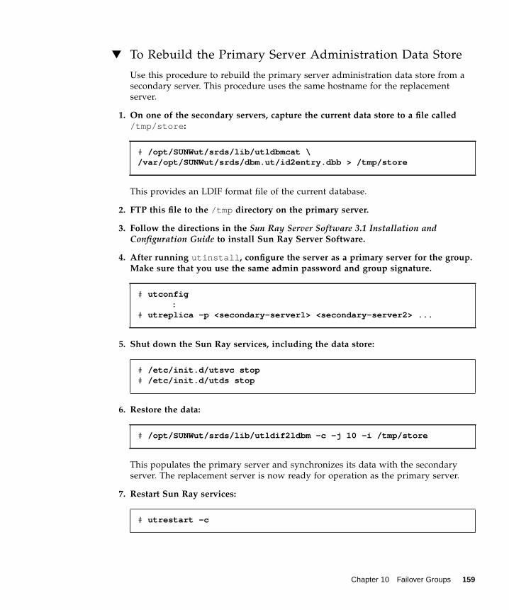
▼ To Rebuild the Primary Server Administration Data Store
Use this procedure to rebuild the primary server administration data store from asecondary server. This procedure uses the same hostname for the replacementserver.
1. On one of the secondary servers, capture the current data store to a file called/tmp/store:
This provides an LDIF format file of the current database.
2. FTP this file to the /tmp directory on the primary server.
3. Follow the directions in the Sun Ray Server Software 3.1 Installation andConfiguration Guide to install Sun Ray Server Software.
4. After running utinstall, configure the server as a primary server for the group.Make sure that you use the same admin password and group signature.
5. Shut down the Sun Ray services, including the data store:
6. Restore the data:
This populates the primary server and synchronizes its data with the secondaryserver. The replacement server is now ready for operation as the primary server.
7. Restart Sun Ray services:
# /opt/SUNWut/srds/lib/utldbmcat \/var/opt/SUNWut/srds/dbm.ut/id2entry.dbb > /tmp/store
# utconfig:
# utreplica -p <secondary-server1> <secondary-server2> ...
# /etc/init.d/utsvc stop# /etc/init.d/utds stop
# /opt/SUNWut/srds/lib/utldif2ldbm -c -j 10 -i /tmp/store
# utrestart -c
Chapter 10 Failover Groups 159
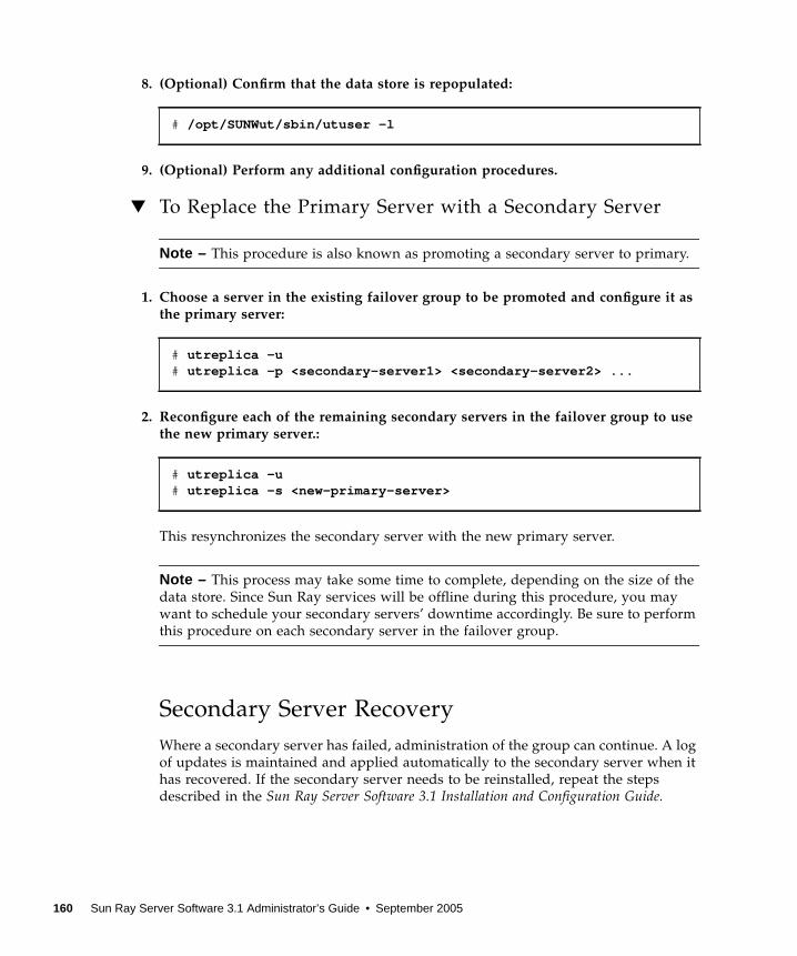
8. (Optional) Confirm that the data store is repopulated:
9. (Optional) Perform any additional configuration procedures.
▼ To Replace the Primary Server with a Secondary Server
Note – This procedure is also known as promoting a secondary server to primary.
1. Choose a server in the existing failover group to be promoted and configure it asthe primary server:
2. Reconfigure each of the remaining secondary servers in the failover group to usethe new primary server.:
This resynchronizes the secondary server with the new primary server.
Note – This process may take some time to complete, depending on the size of thedata store. Since Sun Ray services will be offline during this procedure, you maywant to schedule your secondary servers’ downtime accordingly. Be sure to performthis procedure on each secondary server in the failover group.
Secondary Server RecoveryWhere a secondary server has failed, administration of the group can continue. A logof updates is maintained and applied automatically to the secondary server when ithas recovered. If the secondary server needs to be reinstalled, repeat the stepsdescribed in the Sun Ray Server Software 3.1 Installation and Configuration Guide.
# /opt/SUNWut/sbin/utuser -l
# utreplica -u# utreplica -p <secondary-server1> <secondary-server2> ...
# utreplica -u# utreplica -s <new-primary-server>
160 Sun Ray Server Software 3.1 Administrator’s Guide • September 2005

Setting Up a Group SignatureThe utconfig command asks for a group signature if you chose to configure forfailover. The signature, which is stored in the /etc/opt/SUNWut/gmSignaturefile, must be the same on all servers in the group.
The location can be changed in the gmSignatureFile property of theauth.props file.
To form a fully functional failover group, the signature file must:
■ be owned by root with only root permissions■ contain at least eight characters, in which at least two are letters and at least one
is not
Tip – For slightly better security, use long passwords.
▼ To Change the Group Manager Signature File
1. As superuser of the Sun Ray server, open a shell window and type:
You are prompted for the signature.
2. Enter it twice identically for acceptance.
3. For each Sun Ray server in the group, repeat the steps, starting at step 1.
Note – It is important to use the utgroupsig command, rather than any othermethod, to enter the signature. utgroupsig also ensures that internal databasereplication occurs properly.
Taking Servers OfflineBeing able to take servers offline makes maintenance easier. In an offline state, nonew sessions are created. However, old sessions continue to exist and can bereactivated unless Sun Ray Server Software is affected.
# /opt/SUNWut/sbin/utgroupsig
Chapter 10 Failover Groups 161

▼ To Take a Server Offline
● At the command-line interface, type:
▼ To Bring a Server Online
● At the command-line interface, type:
# /opt/SUNWut/sbin/utadm -f
# /opt/SUNWut/sbin/utadm -n
162 Sun Ray Server Software 3.1 Administrator’s Guide • September 2005

APPENDIX A
User Settings and Concerns
Supported Devices and LibrariesSun Ray Server Software supports a wide variety of end-user devices, includingend-user peripherals that can be connected to a Sun Ray DTU’s serial, parallel, orUSB ports; however, because of the growing number of USB devices available, it hasnot been possible to test all of them on Sun Ray DTUs.
Sun Ray DTU SettingsSun Ray Settings is an interactive GUI that allows the user to view and change thesettings for the Sun Ray DTU that the user is currently logged into.
The Sun Ray Settings GUI contacts the Session Manager to determine which DTU iscurrently being used and connects to that unit to get the current values. The GUImaintains a connection to the Session Manager so that the Session Manager cannotify the GUI if the user moves to another DTU by removing the smart card andinserting it into another DTU.
▼ To Change the Sun Ray Settings1. Press the hot key (by default Shift-Props).
The Sun Ray Settings window is displayed.
163

FIGURE A-1 Settings Screen
2. Use the Category pull-down menu to access Audio Output, Audio Input, Display,and Video settings.
3. To change a setting, move the appropriate scroll bar, checkbox, or pull-downmenu.
The DTU is updated immediately.
The only exception is the “Resolution/Refresh Rate” setting, which prompts the userwith confirmation dialog boxes before and after the change is made on the DTU.
4. Press the hot key to close the window.
Note – Only one instance per session of Sun Ray Settings runs in hot key mode.
Monitor SettingsSun Ray users can modify their screen resolution settings by invoking utsettings.
Any resolution selections made within a session remain effective whenever thesession is displayed on that particular DTU. The selection is not lost if the unit goesinto power-save mode or is power-cycled; however, the resolution settings selectedthrough utsettings apply only to the DTU where utsettings is run.
164 Sun Ray Server Software 3.1 Administrator’s Guide • September 2005

When a user moves to another DTU, the resolution settings do not accompany theuser to the new DTU, but the settings remain effective for the user’s session on theoriginal DTU if the returns to it via hotdesking.
If the session is associated with a personal mobile token, then utsettings offers tomake the selected timing permanent. If a user accepts that offer, then the timing isretained and reused on that user’s subsequent personal mobile token sessions on thesame DTU.
In addition, the administrator can use the utresadm command to:
■ Arrange for a particular monitor timing to be used whenever a specific token ispresented on a specific DTU.
■ Arrange for a particular monitor timing to be used on a specific DTU, regardlessof the token that is presented at the DTU.
■ Arrange for a particular monitor timing to be used on all DTU’s regardless of thetoken that is presented at the DTU.
Any conflict among settings is resolved in favor of the most specific configurationrule. That is, a configuration record for a specific token at a specific DTU takesprecedence over a record for any token at that specific DTU, and a configurationrecord for any token at a specific DTU takes precedence over a record for any token atany DTU.
Hot Key PreferencesHot keys can be configured for various Sun Ray utilities. The scope for these hotkeys can be:
■ System-wide default setting■ User default setting■ System-wide mandatory setting
Appendix A User Settings and Concerns 165

To support these levels of customization, the utilities look for the properties files inTABLE A-1, in the following order, at startup:
If your policy is for all DTUs to use a standard hot key, use the system-widemandatory defaults file to specify this standard key. This prevents users fromspecifying their own hot key preferences.
The format of the hot key entry in these properties files is:
where <utility_name> is the name of the utility, such as utsettings or utdetach,and value is a valid X keysym name preceded by one or more of the supportedmodifiers (Ctrl, Shift, Alt, Meta) in any order. Values are shown in TABLE A-2.
TABLE A-1 Sun Ray Settings Properties Files
File Scope Description
/etc/opt/SUNWut/utslaunch_defaults.properties System This file contains helpful defaultproperties. Any properties specifiedhere override any defaults built intothe application itself.
$HOME/.utslaunch.properties User This file contains the user’s preferredvalues, which override any applicationor site-wide defaults.
/etc/opt/SUNWut/utslaunch_mandatory.properties Mandatory This file contains site-wide mandatorysettings that cannot be overridden bythe user. These properties override anyapplication, site-wide, or user defaults.
<utility_name>.hotkey=value
TABLE A-2 Specific Hot Key Values
Example Value Notes
Shift+Props This brings up the Settings GUI.
Ctrl+Alt+Backspace Press this key sequence twice to kill a session.
Ctrl+Alt+Del Press this key sequence twice to kill the process that hastaken control of the X server.
Shift+Pause This detaches a non-smart card mobility session.
Mute+Softer+Louder This displays the DTU’s MAC address.
Ctrl+Power This cycles power.
166 Sun Ray Server Software 3.1 Administrator’s Guide • September 2005

Hot Key Values
▼ To Change the Hot Key for the Settings GUIIf you do not want to use the Sun Props key as your default hot key, use the system-wide defaults file to specify a function key. Users can still specify their preferences inthe user defaults file.
Use this procedure to modify the settings GUI for all users on a server.
1. As superuser, open the /etc/opt/SUNWut/utslaunch_defaults.propertiesfile in a text editor.
Tip – If you want to make the change mandatory, change the value in the/etc/opt/SUNWut/utslaunch_mandatory.properties file.
2. Locate the original hot key entry for the utdetach utility and place a # in front ofthat statement.
The # comments out the first hot key property.
3. Type in the new hot key property after the first statement. For example,
4. Save the utslaunch_defaults.properties file.
The new hot key takes effect when the next user logs in. The next user to log in usesthe new hot key to display the Sun Ray Settings screen. Users who were logged inbefore you changed the hot key continue to use the old value.
▼ To Change the Hot Key Setting for a Single User1. In the user’s home directory, create the .utslaunch.properties file.
# utdetach.hotkey=Shift Pause
utsettings.hotkey=Shift F8
Appendix A User Settings and Concerns 167

Note – Make sure that the user owns and can read this file.
2. Add a line to the .utslaunch.properties file with the value for the hot key.For example:
3. Save the .utslaunch.properties file.
4. Log out and log back in to enable the new hot key.
Note – You can modify other hot keys in a similar fashion.
Power Cycling a Sun Ray DTU
▼ To Power Cycle a Sun Ray DTU● Disconnect then reconnect the power cord.
▼ To Perform a Soft Reset● Use the key sequence Ctrl-Power (the Power key at the right side of the top row
of the Sun Type 6 keyboard has crescent moon icon).
▼ To Kill a User’s Session● Use the key sequence Ctrl-Alt-Backspace twice.
This kills the Xserver process, alerting the current session’s parent process to startanother session.
utsettings.hotkey=Shift F8
168 Sun Ray Server Software 3.1 Administrator’s Guide • September 2005

APPENDIX B
Troubleshooting and Tuning Tips
This appendix contains the following sections:
■ “Understanding OSD” on page 169■ “Authentication Manager Errors” on page 181■ “Audio” on page 184■ “Performance Tuning” on page 185
Understanding OSDSun Ray Server Software on-screen displays (OSD) to help administrators and othersidentify problems visually. The most important information about the Sun Ray DTUand its current state is displayed on the screen.
OSD Icon TopographyThe OSD icons display:
■Ethernet address■Currently assigned IP address of the DTU■Link status of the currently connected Sun Ray server■Authentication Server IP address■ Icon code and DHCP state
To help you locate problems, the OSD icons display anumeric icon code followed by an alphabetic DHCP state
code. You can look up the meaning of the numeric OSD message codes in TABLE B-1and the alphabetic DHCP state codes in TABLE B-2. Encryption and authenticationinformation is also displayed when appropriate.
169

Note – Sun Ray DTUs can function in a private interconnect or in a simple LANenvironment with only an IP address, but additional basic parameters and Sun Ray-specific vendor options are needed for more complex LAN operations, such as whena DTU is located several hops away from the Sun Ray Server’s subnet.
Tip – It is always a good idea to make sure that you are using the latest firmware.See “Managing Firmware Versions” on page 29.
OSD icon messages and codes are summarized in the following tables:
TABLE B-1 Icon Messages
Icon Code Meaning
1 Sun Ray unit is starting up and is waiting for ethernet link
2 Sun Ray unit is downloading new firmware
3 Sun Ray unit is storing new firmware in its flash memory
4 Either the download or storage of new firmware has failed
5 There is no session to connect with the Sun Ray
6 The server is denying access to the Sun Ray
7 Local pin entry to the smart card has failed
8 In local smartcard pin entry mode
9 There is an over current condition on the USB bus, i.e., the total number of devices draws too muchcurrent. Consider using a powered hub.
11 Server is authenticated by the Sun Ray and the graphic/keyboard network connection is encrypted
12 The Sun Ray cannot authenticate the server but the graphic/keyboard network connection is stillbeing encrypted
13 Server authenticated to the Sun Ray; network connection between Sun Ray and server not encrypted
14 Server not authenticated to the Sun Ray; graphic/keyboard network connection is not encrypted
15 The Sun Ray is refusing to talk to the server due to the server’s refusal or inability to authenticate orencrypt the network connection
16 The Sun Ray USB bus is temporarily busy servicing a high-speed device, and the keyboard or mousemay not be responsive to user input.
21 The Sun Ray unit is booting up and is waiting on DHCP IP address and parameter assignment.
22 The Sun Ray unit is booting up and is now waiting for the initial connection to a Sun Ray server.
23 The connection between the Sun Ray and the network is down. Check the network drop cable and (ifthe network drop cable is okay) the network switch.
170 Sun Ray Server Software 3.1 Administrator’s Guide • September 2005

24 The Sun Ray has disconnected from the previous server.
25 The Sun Ray is being redirected to a new server.
26 The Sun Ray has connected to the server and is waiting for graphics traffic (this is the GNC state).
27 The Sun Ray is broadcasting to locate a Sun Ray server since either it was not provided with Sun Rayspecific DHCP parameters or all of the specified servers are not responding.
Icon numbers 31 through 34 are the network status display brought up by the user pressing all three audio keys.
31 The network link is up, the server is authenticated, and graphics/keyboard network connections arenot encrypted.
32 The network link is up, the server is not authenticated, and graphics/keyboard network connectionsare encrypted.
33 The network link is up, the server is authenticated and graphics/keyboard are encrypted.
34 The network link is up, the server is not authenticated and graphics/keyboard are not encrypted.
50 The server is refusing to talk to the Sun Ray due to the Sun Ray’s refusal or inability to authenticateor encrypt the network connection
TABLE B-2 DCHP State Codes
DCHP State Code State Meaning
A DCHP only provided IP address with no additional parameters
B DCHP provided IP address, subnet mask, and router, but Sun Ray vendor-specificparameters are missing.
C DHCP provided IP address and Sun Ray vendor-specific parameters, but subnet mask androuter are missing.
D DHCP provided all expected parameters.
TABLE B-3 Power LED
DTU Hardware State Action to Take
Off Check to see if the DTU is plugged in. Replace the DTU.
Amber Hardware fault. Replace the DTU.
Blinking PROM is corrupted. Check that firmware downloads are properlyconfigured and enabled. Then power cycle the DTU.
Card reader LED remains on evenwhen smart card is removed
Card reader hardware problem. Replace the DTU.
TABLE B-1 Icon Messages
Icon Code Meaning
Appendix B Troubleshooting and Tuning Tips 171
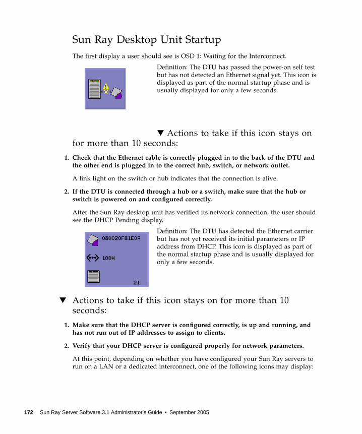
Sun Ray Desktop Unit StartupThe first display a user should see is OSD 1: Waiting for the Interconnect.
Definition: The DTU has passed the power-on self testbut has not detected an Ethernet signal yet. This icon isdisplayed as part of the normal startup phase and isusually displayed for only a few seconds.
▼ Actions to take if this icon stays onfor more than 10 seconds:
1. Check that the Ethernet cable is correctly plugged in to the back of the DTU andthe other end is plugged in to the correct hub, switch, or network outlet.
A link light on the switch or hub indicates that the connection is alive.
2. If the DTU is connected through a hub or a switch, make sure that the hub orswitch is powered on and configured correctly.
After the Sun Ray desktop unit has verified its network connection, the user shouldsee the DHCP Pending display.
Definition: The DTU has detected the Ethernet carrierbut has not yet received its initial parameters or IPaddress from DHCP. This icon is displayed as part ofthe normal startup phase and is usually displayed foronly a few seconds.
▼ Actions to take if this icon stays on for more than 10seconds:
1. Make sure that the DHCP server is configured correctly, is up and running, andhas not run out of IP addresses to assign to clients.
2. Verify that your DHCP server is configured properly for network parameters.
At this point, depending on whether you have configured your Sun Ray servers torun on a LAN or a dedicated interconnect, one of the following icons may display:
172 Sun Ray Server Software 3.1 Administrator’s Guide • September 2005

Startup Wait for DHCP Information
After the DHCP server has allocated an IP address, theicon is updated with the unit’s IP address; if the responseis inadequate, the Sun Ray issues a DHCP inform requestto attempt to obtain the Sun Ray vendor-specificparameters. The Sun Ray continues all the way throughbooting with just a DHCP supplied IP address but usuallyfunctions better with some additional parameters.
Code 21 A indicates that the DTU got an IP address and iswaiting for a DHCP inform response to other parameters.
Code 21 B indicates that the DTU got an IP address and IProuter and is waiting for Sun Ray vendor-specific optionsfrom DHCP inform.
Note – If you see a 21 A or 21 B with a DTU IP address in a LAN deployment, theSun Ray DTU is trying to use DHCP_INFORM to get Sun Ray-specific parameters.
▼ Actions to take:
1. For LAN configurations with other (non-Sun Ray) DHCP services but no bootpproxy agent, verify the DHCP server and the Sun Ray vendor tags.
2. For routed configurations, verify that the bootp proxy agent is configuredcorrectly in the Sun Ray DTU’s subnet and that it points to one of the Sun Rayservers in the failover group.
3. For non-routed private interconnect configurations, the Sun Ray server alsoperforms the functions of a DHCP server. Verify that it is configured properly forDHCP services.
When DHCP has finished, the Sun Ray DTU tries to connect to a Sun Ray server andthe authentication manager that is running on that server.
Waiting to Connect to Authentication Manager
Definition: The DTU has received its initial parametersfrom DHCP but has not yet connected to the Sun RayAuthentication Manager. This icon is displayed as part ofthe normal startup phase and is usually displayed foronly a few seconds.
Icon 21B
Appendix B Troubleshooting and Tuning Tips 173

▼ Actions to take if the icon displays for more than a fewseconds or if the DTU continues to reset after the icon isdisplayed:
1. Make sure that the Sun Ray services, including the Authentication Manager, areup and running on the Sun Ray server.
In a LAN configuration or other routed environment:
2. Make sure that the authentication manager can be reached from the IP addressassigned to the DTU.
3. Verify that the routing information the DTU receives is correct.
4. Run utquery for the DTU’s IP address.
The utquery command displays the parameters a Sun Ray DTU has received. Ifutquery fails to display an AuthSrvr parameter, the DHCP server for Sun Rayparameters may not be reachable or may not be configured properly. Confirm thatthe DHCPServer and INFORMServer values are appropriate. If not, look at yourbootp relay configurations and DHCP server configurations for network and SunRay parameters. For details of these parameters, see the utquery man page.
▼ To Identify a Hung Session
● As superuser, type:
▼ To Kill a Hung Session
● As superuser, type:
# /opt/SUNWut/sbin/utdesktop -l -w
# /opt/SUNWut/sbin/utsession -k -t token
174 Sun Ray Server Software 3.1 Administrator’s Guide • September 2005

Firmware DownloadDownloading PROM Software
Definition: The DTU is currently downloading new flashPROM software from the Sun Ray server.
▼ Actions to take:
1. Wait until the download is complete.
Downloading and saving the new PROM software usually takes less than a minute.If you interrupt the download, the DTU has to download new PROM software thenext time it reboots.
If the firmware download fails, the following syslog message indicates that thebarrier level has been set to prevent Sun Ray DTUs with SRSS 3.1 firmware fromautomatically downloading an earlier version of the firmware:
2. Check /var/opt/SUNWut/log/messages to confirm that your configuration isset up properly.
Note – For LAN configurations, the minimum barrier level is 200.
Saving PROM Software
Definition: The DTU has just downloaded new PROMsoftware from the Sun Ray server and is saving it to theDTU’s PROM.
Firmware upgrade/downgrade not allowed! Barrier is 310 Firmware level is 0
Icon 3
Appendix B Troubleshooting and Tuning Tips 175

▼ Actions to take:
● Wait until the download is done.
Downloading and saving the new PROM software usually takes less than a minute.If you interrupt the download, the DTU has to download new PROM software thenext time it reboots.
Firmware Download Failed
Definition: The DTU has failed to download newfirmware.
▼ Actions to take:
1. Check the messages file /var/opt/SUNWut/log/messages to verify the versionnumber.
2. Correct, if necessary, with utadm -l.
Bus BusySun Ray USB Bus Busy
Definition: The Sun Ray USB bus is temporarily busyservicing a high-speed device, and the keyboard or mousemay not be responsive to user input.
This icon typically appears only during an unusually longprint job and disappears when the job is done. This is aninformational OSD; there is no particular action to takeunless it is necessary to kill the print job.
Icon 4A
176 Sun Ray Server Software 3.1 Administrator’s Guide • September 2005
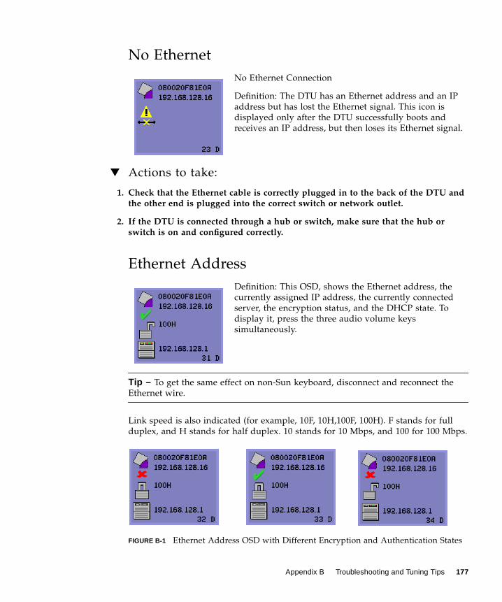
No EthernetNo Ethernet Connection
Definition: The DTU has an Ethernet address and an IPaddress but has lost the Ethernet signal. This icon isdisplayed only after the DTU successfully boots andreceives an IP address, but then loses its Ethernet signal.
▼ Actions to take:
1. Check that the Ethernet cable is correctly plugged in to the back of the DTU andthe other end is plugged into the correct switch or network outlet.
2. If the DTU is connected through a hub or switch, make sure that the hub orswitch is on and configured correctly.
Ethernet AddressDefinition: This OSD, shows the Ethernet address, thecurrently assigned IP address, the currently connectedserver, the encryption status, and the DHCP state. Todisplay it, press the three audio volume keyssimultaneously.
Tip – To get the same effect on non-Sun keyboard, disconnect and reconnect theEthernet wire.
Link speed is also indicated (for example, 10F, 10H,100F, 100H). F stands for fullduplex, and H stands for half duplex. 10 stands for 10 Mbps, and 100 for 100 Mbps.
FIGURE B-1 Ethernet Address OSD with Different Encryption and Authentication States
Icon 23
Appendix B Troubleshooting and Tuning Tips 177
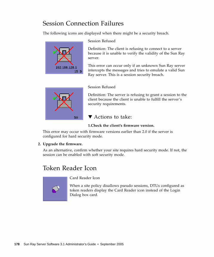
Session Connection FailuresThe following icons are displayed when there might be a security breach.
Session Refused
Definition: The client is refusing to connect to a serverbecause it is unable to verify the validity of the Sun Rayserver.
This error can occur only if an unknown Sun Ray serverintercepts the messages and tries to emulate a valid SunRay server. This is a session security breach.
Session Refused
Definition: The server is refusing to grant a session to theclient because the client is unable to fulfill the server’ssecurity requirements.
▼ Actions to take:
1.Check the client’s firmware version.
This error may occur with firmware versions earlier than 2.0 if the server isconfigured for hard security mode.
2. Upgrade the firmware.
As an alternative, confirm whether your site requires hard security mode. If not, thesession can be enabled with soft security mode.
Token Reader IconCard Reader Icon
When a site policy disallows pseudo sessions, DTUs configured astoken readers display the Card Reader icon instead of the LoginDialog box card.
178 Sun Ray Server Software 3.1 Administrator’s Guide • September 2005
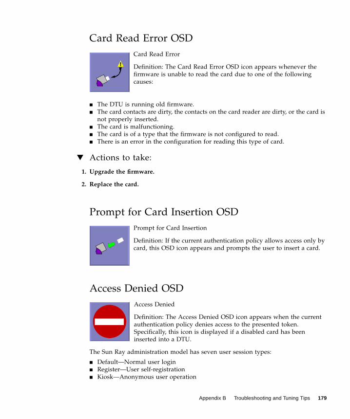
Card Read Error OSDCard Read Error
Definition: The Card Read Error OSD icon appears whenever thefirmware is unable to read the card due to one of the followingcauses:
■ The DTU is running old firmware.■ The card contacts are dirty, the contacts on the card reader are dirty, or the card is
not properly inserted.■ The card is malfunctioning.■ The card is of a type that the firmware is not configured to read.■ There is an error in the configuration for reading this type of card.
▼ Actions to take:
1. Upgrade the firmware.
2. Replace the card.
Prompt for Card Insertion OSDPrompt for Card Insertion
Definition: If the current authentication policy allows access only bycard, this OSD icon appears and prompts the user to insert a card.
Access Denied OSDAccess Denied
Definition: The Access Denied OSD icon appears when the currentauthentication policy denies access to the presented token.Specifically, this icon is displayed if a disabled card has beeninserted into a DTU.
The Sun Ray administration model has seven user session types:
■ Default—Normal user login■ Register—User self-registration■ Kiosk—Anonymous user operation
Appendix B Troubleshooting and Tuning Tips 179

■ Insert card—User smart card required■ Card error—Unrecognized user smart card type■ No entry—User’s smart card token is blocked■ Session Refused—The server refuses to grant a session to a client that does not
meet the server’s security requirements
The first three session types have normal login processes. When there is a problem,the administrator should examine:
■ Sun Ray Server configuration files
Caution – Sun Ray Server Software modifies certain system configuration files. Inmost cases, these changes are identified with SRSS-specific comments. Please do notchange these modifications.
■ Any locally modified X server startup files■ dtlogin status
Although the last four session types display icons on the Sun Ray DTU, they do nothave login processes at all. The icons indicate that the user must take steps before asuccessful login is possible. If the user immediately removes and reinserts the smartcard, the icon disappears, but the Wait for Session OSD remains.
These last four session types and their OSDs should not cause alarm. The user can:
■ Insert a recognized smart card in the correct orientation■ Ask the Sun Ray administrator to grant access■ Ask the Sun Ray administrator to download the correct firmware
Wait for Session OSDWait for Session
This OSD represents the transition state for the Sun RayDTU. If it is displayed for an extended period, there isprobably no X Window server running.
Note – The current wait icon is a white “X” cursor. Inearlier releases, the wait icon was displayed as a green newt cursor.
180 Sun Ray Server Software 3.1 Administrator’s Guide • September 2005

Wait Icon Cursor for Default Session TypeThis section applies to a normal dtlogin session.
The Xsun server is indirectly started by the dtlogin daemon. In the process ofstarting the Xsun server, the dtlogin daemon reads two configuration files:
■ /etc/dt/config/Xservers■ /etc/dt/config/Xconfig
If, after several retries, the Xsun process does not start, the dtlogin daemon justgives up. The problem can usually be traced back to an older version of thedtlogin daemon or the configuration files for the dtlogin daemon.
PatchesFor the latest information regarding Sun Ray Server Software patches, check:
http://www.sun.com/software/sunray/patches.xml
Authentication Manager ErrorsAuthentication Manager errors can be found in the following error logs:
■ Installation logs:
■ /var/adm/log■ /var/opt/SUNWut/log
■ General log files:
■ /var/opt/SUNWut/srds/log■ /var/opt/SUNWut/srds/replog
The general format of the log messages is:
timestamp thread_name message_class message
For example:
May 7 15:01:57 e47c utauthd: [ID 293833 user.info] Worker3NOTICE: SESSION_OK pseudo.080020f8a5ee
Appendix B Troubleshooting and Tuning Tips 181

Message components are defined as follows:
■ timestamp format:
year.month.day hours:minutes:seconds
■ thread_name
There are several different types of threads. The most common thread handlesDTU authentication, access control, and session monitoring. These threads arenamed “worker” plus number. The Worker# thread names are reused when aconnection terminates. Other threads are:
■ SessionManager#—Communicate with utsessiond on behalf of a Worker#thread.
■ AdminJobQ—Used in the implementation to wrap a library that would nototherwise be thread-safe.
■ CallBack#—Communicate with applications such as utload.■ WatchID—Used to poll data/terminals from connections■ Terminator—Cleans up terminal sessions■ Group Manager—Main group manager thread
■ message_class
Messages with the same thread name are related. The exception occurs when aWorker# thread disconnects a DTU and then purges the connection informationfrom memory. After a Worker# DESTROY message, the next use of that Worker#thread name has no relation to previous uses of the thread name (in other words,the thread names are reused).
■ CLIENT_ERROR—Indicates unexpected behavior from a DTU. These messagescan be generated during normal operation if a DTU is rebooted.
■ CONFIG_ERROR—Indicates a system configuration error. The AuthenticationManager generally exits after one of these errors is detected.
■ NOTICE—Logs normal events.■ UNEXPECTED—Logs events or conditions that were not anticipated for normal
operation but are generally not fatal. Some of these errors should be brought tothe attention of the Sun Ray product development team.
■ DEBUG—Only occurs if explicitly enabled. Beneficial to developers. Debugmessages can reveal session IDs, which must be kept secret to ensure propersecurity.
182 Sun Ray Server Software 3.1 Administrator’s Guide • September 2005

TABLE B-4 Error Message Examples
Error class Message Description
CLIENT_ERROR ...Exception ... : cannot sendkeepAliveInf
Error encountered while attempting tosend a keep-alive message to a DTU.
...keepAlive timeout A DTU has failed to respond within theallotted time. The session is beingdisconnected.
duplicate key: DTU does not properly implement theauthentication protocol.
invalid key: DTU does not properly implement theauthentication protocol.
CONFIG_ERROR attempt to instantiate CallBack 2ndtime.
Program error.
AuthModule.load Problem encountered while loadingconfiguration module.
Cannot find module Program or installation error.
NOTICE “discarding response: “ + param No controlling application is present toreceive DTU response.
”NOT_CLAIMED PARAMETERS: “ + param A token was not claimed by anyauthentication module.
...authentication module(s) loaded. Notification that authentication moduleshave loaded.
...DISCONNECT ... Normal notification of disconnection.
UNEXPECTED “CallBack: malformed command” Bad syntax from a user application suchas utload or utidle.
.../ ... read/0:” + ie Possible program error.
.../ ... read/1: ... Exception ... Error encountered while readingmessages from the DTU.
.../... protocolError: ... Various protocol violations are reportedwith this message. This is also a way forutauthd to force the DTU to reset.
Appendix B Troubleshooting and Tuning Tips 183

AudioEach time a user logs in to a Sun Ray DTU, a script automatically assigns the$AUDIODEV environment variable to that session. One utaudio(1)real-time processis assigned to each session. Refer to the audio(7i)man page for more information.
Audio Device EmulationThe emulated audio device follows the user session during hotdesking. The devicename appears in the $AUDIODEV environment variable but is transparentlyinterpreted by audio programs for Sun systems. Device nodes are created in the/tmp/SUNWut/dev/utaudio directory. The directory tree is completely recreated atboot time.
Caution – Do not remove the /tmp/SUNWut/dev/utaudio directory. Deleting thisdirectory prevents existing users with utaudio sessions from using their audiopseudo device nodes.
If your application uses /dev/audio, the Sun Ray server software reroutes theaudio signal appropriately.
Audio MalfunctionIf audio features are malfunctioning:
1. To confirm whether audio is working, run the following command on the DTU:
2. Bring up utsettings:
3. Verify that audio output is selected properly, e.g., for headphones or speakers.
4. Check the volume level.
5. Verify that Mute is not selected.
% cat /usr/demo/SOUND/sounds/whistle.au >/$AUDIODEV
% utsettings
184 Sun Ray Server Software 3.1 Administrator’s Guide • September 2005

Some applications are hard-coded to use /dev/audio for output. Sun Ray SystemSoftware provides a redirection library that you can use to correct this behavior.
▼ To Activate the Redirection Library
1. Set the environment variable LD_PRELOAD to libc_ut.so in the shell or wrapperfrom which you started the audio player:
2. Restart the application.
Performance TuningSome applications, such as intensive 3-D visual simulations, may run very slowly onSun Ray. Other applications, such as pseudo-stereo viewers using double-buffering,or high-frequency dynamic color table flips on 8-bit visuals, do not produce theexpected visual result.
General ConfigurationYou can usually improve performance by configuring /etc/system shared memorysegment parameters. The exact settings depend on application demands and thenumber of Sun Ray users, but a convenient starting point is:
Due to the nature of the Xinerama (single virtual X display) mode of multihead, thesystem shared memory requirements may be even higher. To get reasonableperformance, the shmsys:shminfo_shmmax parameter must be at least:
# setenv LD_PRELOAD libc_ut.so
set shmsys:shminfo_shmmax = 0x2000000set shmsys:shminfo_shmmni = 0x1000set shmsys:shminfo_shmseg = 0x100
LARGEST_NUMBER_OF_HEADS * width * height * 4
Appendix B Troubleshooting and Tuning Tips 185

ApplicationsPlacing the user’s interactive applications, such as Netscape or StarOffice, or PCinteroperability tools, such as Citrix or Tarantella, on the Sun Ray server usuallyhelps performance by reducing network load. The applications benefit from fastertransport of commands to the Sun Ray’s X server.
Applications that can be configured to use shared memory instead of DGA oropenGL usually perform better on Sun Ray when they used shared memory.
Sluggish PerformanceSluggish Sun Ray server performance or excessive disk swapping is an indicationthat the Sun Ray server is under-provisioned. Under these circumstances, there isnot enough virtual memory available to start an X Window server instance for auser’s session.
The solution in this situation is to add more memory or increase the size of the swappartition. In other situations, network load or packet loss may be too high. In veryrare cases, network cables or switch equipment may be defective.
1. To determine whether there is excessive swapping, use vmstat 5.
If there is excessive swapping, the system may be undersized or overutilized.
2. Verify that network connections are 100F.
3. Use utcapture to assess network latency and packet loss.
As latency and packet loss increase, performance suffers.
Monitor Display Resolution Defaults to 640 x 480First, eliminate the most obvious possible causes:
■ An older monitor■ A bad cable■ Monitor was off when the Sun Ray DTU was started
If the Sun Ray DTU is unable to read DDC data from the monitor, then it defaults to640 x 480 pixels.
# vmstat 5
186 Sun Ray Server Software 3.1 Administrator’s Guide • September 2005

▼ To Correct or Reset the Screen Resolution:
1. Replace the cable
2. Restart the Sun Ray DTU after powering the monitor on
3. Replace the monitor
4. Use the utresadm to set persistent display setting to override the default.
Old Icons (Hourglass with Dashes Underneath)Appear on DisplayIf the old icons appear on the display, either the DTU’s firmware has not beenupgraded or it is failing.
1. Upgrade the firmware to SRSS 3.1.
2. Follow the procedure to upgrade the firmware. See the Sun Ray Software 3.1Installation and Configuration Guide.
You may need to use a dedicated private network.
Port Currently Owned by Another ApplicationIf this message displays, use the following procedure to correct it:
1. Download the latest Java Communications API (javax.comm API version 2.0.2 andabove)
2. Make sure that the supported USB-Serial Adapter is used.
The supported USB devices list is available at
http://www.sun.com/io_technologies/sunray/usb/
3. Click the Change Synchronization Settings icon and select the appropriate port (towhich the Palm cradle should be connected), then click OK.
4. If the ports are not correctly shown in the Serial Port drop down menu, close theapplication and hot plug the device.
5. Start the application again.
Appendix B Troubleshooting and Tuning Tips 187

Design Tips■ Avoid drawing into off-screen memory and then copying large areas to the screen.
This technique produces slow Sun Ray performance.■ GXcopy mode is usually the fastest drawing mode.■ To display large images, use shared memory pixmaps, if possible.■ Opaque stipple patterns are faster than transparent stipples.■ Opaque (image) text is faster then other text.
188 Sun Ray Server Software 3.1 Administrator’s Guide • September 2005

CHAPTER
Glossary
AAMGH See regional hotdesking.
Bbackplane bandwidth Sometimes also referred to as switch fabric. A switch’s backplane is the pipe
through which data flows from an input port to an output port. Backplanebandwidth usually refers to the aggregate bandwidth available amongst allports within a switch.
barrier mechanism To prevent clients from downloading firmware that is older than the firmwarethey already have, the administrator can set a barrier mechanism. The barriermechanism symbol BarrierLevel is defined by default in the DHCP table ofSun Ray servers running version 2.0 or later of Sun Ray Server Software.
bpp Bits per pixel.
CCAM Controlled access mode, also known as kiosk mode.
189

category 5 The most common type of wiring used in LANs. It is approved for both voiceand data (at up to 100Mhz). Also called cat 5.
client-server A common way to describe network services and the user processes(programs) of those services.
cut-through switches The switch begins forwarding the incoming frame onto the outbound port assoon as it reads the MAC address, while it continues receiving the remainderof the frame.
DDHCP Dynamic Host Configuration Protocol, which is a means of distributing IP
addresses and initial parameters to the DTUs.
domain A set of one or more system boards that acts as a separate system capable ofbooting the OS and running independently of any other board.
EEthernet Physical and link-level communications mechanism defined by the IEEE 802.3
family of standards.
Ethernet address The unique hardware address assigned to a computer system or interfaceboard when it is manufactured. See MAC address.
Ethernet switch A unit that redirects packets from input ports to output ports. It can be acomponent of the Sun Ray interconnect fabric.
Ffailover The process of transferring processes from a failed server to a functional server.
filling station When a client’s firmware is downgraded to an earlier version because itconnects to a server running the earlier version, it needs to be connected to afilling station so that it can download newer firmware. For this purpose, a
190 Sun Ray Server Software 3.1 Administrator’s Guide • September 2005

filling station can be any private network configured for Sun Ray services orany shared network in which the Sun Ray DHCP server is the only DHCPserver.
firmware barrier See barrier mechanism.
FTP File Transfer Protocol. The name of the Internet protocol and the program usedto transfer files between hosts.
GGEM Gigabit Ethernet.
Hhead Colloquial term for a screen, or display, or monitor, especially in a context
where more than one is used in conjunction with the same keyboard andmouse, as in “multihead” feature.
hotdesking The ability for a user to remove a smart card, insert it into any other DTUwithin a server group, and have the user’s session “follow” the user, thusallowing the user to have instantaneous access to the user’s windowingenvironment and current applications from multiple DTUs.
hot key A pre-defined key that causes something to appear on your screen. A hot keyis used to bring up the Settings screen on the Sun Ray DTU.
hot-pluggable A property of a hardware component that can be inserted into or removedfrom a system that is powered on. USB devices connected to Sun Ray DTUs arehot-pluggable.
Iinterconnect fabric All the cabling and switches that connect a Sun Ray server’s network interface
cards to the Sun Ray DTUs.
Chapter Glossary 191

internet A collection of networks interconnected by a set of routers that enable them tofunction as a single, large virtual network.
Internet The largest internet in the world consisting of large national backbone nets(such as MILNET, NSFNET, and CREN) and a myriad of regional and localcampus networks all over the world. It is a global collection of networksconnecting a wide range of computers using a common protocol tocommunicate and share services.
intranet Any network that provides similar services within an organization to thoseprovided by the Internet but which is not necessarily connected to the Internet.
IP address A unique number that identifies each host or other hardware system on anetwork. An IP address is composed of four integers separated by periods.Each decimal integer must be in the range 0-255 (for example, 129.144.0.0).
IP address lease The assignment of an IP address to a computer system for a specified length oftime, rather than permanently. IP address leasing is managed by the DynamicHost Configuration Protocol (DHCP). Sun Ray DTU IP addresses are leased.
Kkiosk mode Same as CAM.
LLAN Local area network. A group of computer systems in close proximity that can
communicate with one another through some connecting hardware andsoftware.
layer 2 The data link layer. In the OSI (Open Standards Interconnection) model, thereare a total of seven layers. Layer 2 is concerned with procedures and protocolsfor operating the communication lines between networks as well as clients andservers. Layer 2 also has the ability to detect and correct message errors.
local host The CPU or computer on which a software application is running.
local server From the client’s perspective, the most immediate server in the LAN.
login The process of gaining access to a computer system.
192 Sun Ray Server Software 3.1 Administrator’s Guide • September 2005

login name The name by which the computer system knows the user.
MMAC address Media Access Control. A MAC address is a 48-bit number programmed into
each local area network interface card (NIC) at the time of manufacture. LANpackets contain destination and source MAC names and can be used bybridges to filter, process, and forward packets. 8:0:20:9e:51:cf is anexample of a MAC address. See also Ethernet address.
mobility For the purposes of the Sun Ray Server Software, the property of a session thatallows it to follow a user from one DTU to another within a server group. Onthe Sun Ray system, mobility requires the use of a smart card or otheridentifying mechanism.
modules Authentication modules are used to implement various site-selectableauthentication policies.
multicasting The process of enabling communication between Sun Ray servers over theirSun Ray network interfaces in a failover environment.
multihead See head.
multiplexing The process of transmitting multiple channels across one communicationscircuit.
Nnamespace A set of names in which a specified ID must be unique.
network Technically, the hardware connecting various computer systems enabling themto communicate. Informally, the systems so connected.
network address The IP address used to specify a network.
network interface An access point to a computer system on a network. Each interface isassociated with a physical device. However, a physical device can havemultiple network interfaces.
network interfacecard NIC. The hardware that links a workstation or server to a network device.
Chapter Glossary 193

network latency The time delay associated with moving information through a network.Interactive applications such as voice, video displays and multimediaapplications are sensitive to these delays.
network mask A number used by software to separate the local subnet address from the restof a given Internet protocol address. An example of a network mask for a classC network is 255.255.255.0.
network protocolstack A network suite of protocols, organized in a hierarchy of layers called a stack.
TCP/IP is an example of a Sun Ray protocol stack.
NIC Network interface card.
non-smart cardmobility A mobile session on a Sun Ray DTU that does not rely on a smart card.
OOSD On-screen display. The Sun Ray DTU uses small OSD icons to alert the user of
potential start-up problems.
Ppatch A collection of files and directories that replace or update existing files and
directories that prevent proper execution of the software on a computersystem. The patch software is derived from a specified package format and canonly be installed if the package it fixes is already present.
policies Authentication Manager, using the selected authentication modules, decideswhat tokens are valid and which users have access.
port (1) A location for passing data in and out of a computer system. (2) Theabstraction used by Internet transport protocols to distinguish among multiplesimultaneous connections to a single destination host.
power cycling Using the power cord to restart a DTU.
194 Sun Ray Server Software 3.1 Administrator’s Guide • September 2005

Rregional hotdesking Originally known as Automatic Multigroup Hotdesking (AMGH), this SRSS
3.1 feature allows users to access their sessions across wider domains andgreater physical distances than was possible in earlier versions of SRSS.Administrators enable this feature by defining how user sessions are mappedto an expanded list of servers in multiple failover groups.
Sscreen flipping The ability to pan to individual screens on a DTU with a single head that were
originally created by a multihead group.
server A computer system that supplies computing services or resources to one ormore clients.
service For the purposes of the Sun Ray Server Software, any application that candirectly connect to the Sun Ray DTU. It can include audio, video, X servers,access to other machines, and device control of the DTU.
session A group of services associated with a single user.
session mobility The ability for a session to “follow” a user’s login ID or a token embedded ona smart card.
smart card A plastic card containing a microprocessor capable of making calculations.
spanning tree The spanning tree protocol is an intelligent algorithm that allows bridges tomap a redundant topology and eliminates packet looping in Local AreaNetworks (LAN).
store-and-forwardswitches The switch reads and stores the entire incoming frame in a buffer, checks it for
errors, reads and looks up the MAC addresses, and then forwards the completegood frame out onto the outbound port.
subnet A working scheme that divides a single logical network into smaller physicalnetworks to simplify routing.
Chapter Glossary 195

TTCP/IP Transmission Control Protocol/Internet Protocol (TCP/IP) is a networking
protocol that provides communication across interconnected networks,between computers with diverse hardware architectures and operatingsystems.
thin client Thin clients remotely access some resources of a computer server, such ascompute power and large memory capacity. The Sun Ray DTUs rely on theserver for all computing power and storage.
timeout value The maximum allowed time interval between communications from a DTU tothe Authentication Manager.
token In the Sun Ray system, a token must be presented by the user. It is required bythe Authentication Manager to consider allowing a user to access the system. Itconsists of a type and an ID. If the user inserted a smart card, the smart card’stype and ID are used as the token. If the user is not using a smart card, theDTU’s built-in type (pseudo) and ID (the unit’s Ethernet address) are suppliedas the token.
UURL Uniform Resource Locator. A standard for writing a textual reference to an
arbitrary piece of data in the World Wide Web (WWW). The syntax of a URL isprotocol://host/localinfo where protocol specifies a protocol to useto fetch the object (like HTTP or FTP), host specifies the Internet name of thehost on which to find it, and localinfo is a string (often a file name) passedto the protocol handler on the remote host.
USB Universal serial bus.
user name The name a computer system uses to identify a particular user. Under UNIXthis is a text string of up to eight characters composed of letters (a-z and A-Z),digits (0-9), hyphens (-), and underscores (_) (for example, jpmorgan). The firstcharacter must be a letter.
196 Sun Ray Server Software 3.1 Administrator’s Guide • September 2005

Vvirtual frame buffer A region of memory on the Sun Ray server that contains the current state of a
user’s display.
VLAN Virtual local area network.
Wwork group A collection of associated users who exist in near proximity to one another. A
set of Sun Ray DTUs that are connected to a Sun Ray server providescomputing services to a work group.
XX server A process which controls a bitmap display device in an X window system. It
performs operations on request from client applications.
Chapter Glossary 197

198 Sun Ray Server Software 3.1 Administrator’s Guide • September 2005

Index
Symbols.parms files, 130
Aadapters, 86admin password, 17, 40Administration Group
viewing failover group status, 156Administration Tool, 38
changing the admin password, 40desktops
displaying current properties, 50editing a single desktop’s properties, 53searching for, 52viewing, 49viewing properties of current user, 51
examining log files, 58finding Sun Ray sessions, 78locating token readers, 44log files
viewing messages logs, 59logging in, 38managing Sun Ray sessions, 78smart card
adding, 64changing the probe order, 63deleting, 64viewing or listing configured, 60viewing the probe order, 63
usersadding a token ID, 74adding a user with token ID, 72deleting, 69
deleting a token ID, 75displaying current properties, 71editing properties, 74enabling or disabling a token ID, 75finding a user, 76getting a token ID from token reader, 77viewing by ID, 67viewing by name, 68viewing current, 71
viewing all multihead groups, 54viewing Sun Ray sessions, 79
AltAuth, 104, 124AMGH, 87appliance, 33
Hot Desking to a multihead group, 140multihead feature, 133multihead group, 133
ARCFOUR, 93attacks
man-in-the-middle, 94AUDIODEV environment variable, 184authentication, 93
server, 94Authentication Manager, 4, 33, 38, 140, 147, 151
configuration file, 152flowchart for primary appliance, 140, 141interacting with Session Manager, 6restarting, 153
AuthPort, 124AuthSrvr, 4, 104, 124, 174
199

Bbandwidth
limited backplane, 9barrier
firmware, 175BarrierLevel, 124bidirectional encryption, 94BOOTP forwarding, 106BYTES SENT, 34
CCabling
fiber-optic, 11CDE toolbar, 134central registration, 5Cisco IOS Executive, 106Cisco IOS-based router, 123Cisco router, 129Citrix, 186client
authentication, 93code
DHCP option, 128command
utadm, 146, 151utcapture
data elements, 33utconfig, 133, 154, 161utmhconfig, 134utreplica, 154utswitch, 21
commandsutadm, 26utadm -r, 29utaudio, 184utfwadm, 29
configurationsecurity, 94, 95
configuration dataDHCP, 26, 145, 148
crontab, 154cursor
green newt, 180X, 180
Ddaemon
data store, 30Data Store, 154data store, 8
primary server, 159regional hotdesking
to configure, 90DCHP
state codes, 171DCHP State Code, 171dedicated interconnect, 108departments, 12desktopID, 34desktops
displaying current properties, 50editing a single desktop’s properties, 53searching for, 52viewing, 49viewing properties of current user, 51
devicedirectory, 81links, 82node ownership, 83nodes, 82USB, 82
DHCP, 146, 173configuring for failover, 148
DHCP Client Class, 125DHCP configuration data, 26, 145, 148DHCP option 49, 123DHCP options
vendor-specific, 124DHCP Relay Agent, 106DHCP relay agent, 117DHCP server, 148DHCP servers, 145DHCPACK, 128DHCPDISCOVER, 105DHCPINFORM, 105, 128DHCPServer, 174directly-connected dedicated interconnect, 111directly-connected shared subnet, 108, 113, 114, 116DNS, 130Domain Name Service, 130
200 SRSS 3.1 Administrator’s Guide • September 2005

DSA, 93dtlogin, 4, 181DTU Hardware State, 171DTU initialization, 103duplicate IP addresses, 26, 145, 148Dynamic Host Configuration Protocol (DHCP), 3
Ee, 145each, 145encapsulated options, 128encryption
algorithm, 93bidirectional, 94downstream only, 94upstream only, 94
environment variablesLD_PRELOAD, 185
errorsout of memory, 26, 145, 148
Ethernet switch, 10
Ffailover
address allocation formula, 146configuring DHCP, 148group, 143
primary server, 154removing replication configuration, 155secondary server, 155
Group Manager module, 145principle components needed, 145server IP addresses, 147setting up group, 154taking servers offline, 161
failover group, 13administration status, 156recovery procedures, 158viewing status, 156
failover groups, 144firmware module, 3
PROM version management, 29FWSrvr, 124, 125, 129
GGDM, 4
gmSignature, 158, 161green newt cursor, 180, 181green newt icon, 180Group Manager
keepalive message, 152load balancing, 2, 153redirection, 19, 152using Authentication Manager properties, 152
Group manager, 151group manager
keepalive message, 151group manager module, 151group signature, 17, 157
setting up, 161GXcopy, 188
Hhacking
man-in-the-middle attacks, 94hard security mode, 94hexadecimal values, 128Hot Desking, 83, 184hot desking, 140hot key, 165
changing setting, 167changing setting site-wide, 167entry, 166values, 166
hotdeskingregional, 87
IIcon Codes, 170icon messages
OSD, 170IEEE802.MACID directory, 81ifname, 111INFORMServer, 174Interconnect, 11interconnect, 10
boost power of, 11dedicated, 108implementing a Sun Ray, 9
interconnect fabric, 8adding an interface, 27
Index 201

deleting an interface, 27departments, 12failover group, 13managing, 26printing configuration, 28removing an interface, 29
interconnect IP address, 26, 145, 148Internal database, 154Intf, 124IOS, 123IP address
duplicate, 26, 145, 148
Kkeepalive message, 151, 152
LLAN, 1LATENCY, 34layer 2 switch, 10LD_PRELOAD environment variable, 185LDIF, 159LED signals, 171libusb, 86load balancing, 2, 153
turning off, 153log files
examining, 58viewing messages logs, 59
LogAppl, 124, 125LogHost, 124, 125login screen, 4LogKern, 124, 125LogNet, 124, 125LogUSB, 124, 125LogVid, 124, 125low-bandwidth deployment, 1, 126
Mman-in-the-middle attack, 94Maximum Transfer Unit (MTU), 129message_class, 182modules, 4
Registered, 5StartSession, 5
MTU, 129multihead, 185
administration tool, 136creating a new group, 137group, 133, 141Hot Desking to an appliance, 140screen display, 135turning on policy from command line, 136turning on policy with administration tool, 136
multihead feature, 133multihead groups
viewing all, 54
NNetscape, 186network
adding an interface, 27deleting an interface, 27removing an interface, 29
NewTBW, 124NewTDispIndx, 124NewTFlags, 124NewTVer, 124, 125non-secure session, 94
OopenGL, 186option 49, 105, 123option code, 128options
encapsulated, 128OSD
icon messages, 170understanding, 169
out of memory error, 26, 145, 148
Ppacket loss
utcapture, 33packets, 127
out-of-order, 127PAM
stack, 88panning, 135parallel peripherals, 81PERCENT LOSS, 34
202 SRSS 3.1 Administrator’s Guide • September 2005

peripherals, 163parallel, 81serial, 81
persistent settings (monitor), 18policies, 4POST, 3power cycle, 168Power LED, 171power–on self test (POST)
firmware module, 3Primary server, 154printers
non-PostScript, 85setting up, 84
PROM, 29ps, 7
Rrdate, 154redirection
Group Manager, 19, 152redundant failover group, 145regional hotdesking, 87Registered module, 5Relay Agent
DHCP, 106remote shared subnet, 108remote subnet, 117Remove replication, 155restart, 136
Sscreen flipping, 140Secondary server, 154secure session, 94security
configuration, 94, 95interconnect, 93session, 95
security modehard, 94soft, 94
security status, 96selectAtLogin, 20self-registration, 5
serial peripherals, 81server
authentication, 93, 94Server addresses, 147Server-to-switch bandwidth, 11service, 6session, 6
changes, 7connection failures, 97finding, 78managing, 78secure vs non-secure, 94viewing, 79
session change, 84Session Manager, 2, 6settings
monitorpersistent, 18
shared memory, 186simple failover group, 144smart card
adding, 64changing the probe order, 63deleting, 64viewing or listing configured, 60viewing the probe order, 63
soft security mode, 94spoofing, 94SRDS, 8StarOffice, 186StartSession module, 5state codes
DHCP, 171status
security, 96subnet
directly-connectedshared, 113, 114, 116
remotedeployment on, 117
Sun Data Store, 17Sun Ray
Data Store, 154Sun Ray administration data, 38
changing, 40Sun Ray administration database
Index 203

usersadding a token ID, 74adding a user with token ID, 72deleting, 69deleting a token ID, 75displaying current properties, 71editing properties, 74enabling or disabling a token ID, 75finding, 76getting a token ID from a token reader, 77viewing by ID, 67viewing by name, 68viewing current, 71
Sun Ray appliance, 1, 2, 33finding sessions, 78firmware module, 3managing sessions, 78multihead feature, 133multihead group, 133shield users, 11viewing sessions, 79
Sun Ray data store daemon, 30Sun Ray DTU
updating and upgrading, 29Sun Ray interconnect
server IP addresses, 147Sun Ray server, 1, 33
device directory, 81network interfaces, 11software, 4viewing all multihead groups, 54
Sun Ray Settingschanging, 163
Sun Ray systemcomputing model, 1
SUNW.NewT.SUNW, 124, 125Switch
high-capacity, 11low-capacity, 11
switchbasic types of 100 Mbps, 11layer 2, 10
syslog, 175
TTarantella, 186TCP, 147
TerminalGroup policy, 140TERMINALID, 33TFTP, 129thread_name, 182TIMESTAMPM, 33token reader
creating, 44getting a token ID from, 77locating, 44
TOTAL LOSS, 33TOTAL PACKET, 33
UUplink ports, 11utaction, 16utadm, 16utadm -A, 116utadm command, 26, 146
available options, 151utadm -L, 117utadm -r command, 29utadminuser, 16utamghadm, 89, 91utaudio command, 184utauthd, 183utcapture, 16, 127utcapture command
data elements, 33utcard, 16, 31utconfig, 16utconfig command, 133, 154, 161utcrypto, 16, 94utdesktop, 16utdetach, 16, 166utdevadm, 24utdsd daemon, 30utdssync, 17utfwadm, 17utfwadm command, 29utfwload, 17utfwsync, 17utgroupsig, 17, 161utgstatus, 17utidle, 183
204 SRSS 3.1 Administrator’s Guide • September 2005

utinstall, 17utload, 183utmhadm, 17, 133utmhconfig, 17, 133utmhconfig command, 134utpolicy, 17utpreserve, 17utpw, 17utquery, 18, 127, 174utreader, 18utreplica, 18utreplica command, 154utresadm, 18, 165utresdef, 18utrestart, 18, 136utselect, 18, 19, 84, 152utsession, 18utsessiond, 7, 182utset, 18utsettings, 18, 164, 166utswitch, 18, 19, 84utswitch command, 21utuser, 18utwall, 18utwho, 18utxconfig, 18
Vv, 17vendor-specific DHCP ptions, 124vendor-specific options, 125virtual frame buffer, 3VLAN, 11
implementing a Sun Ray interconnect, 9multiple configuration, 10
WWAN, 1, 126
XX cursor, 180X Window Display Manager, 105, 123, 125Xconfig, 181XINERAMA, 134, 139
Xinerama, 185Xservers, 181Xsun, 181
Index 205

206 SRSS 3.1 Administrator’s Guide • September 2005
Related Documents