US Selected Assemblies Catalogue #999-901-192 i The Sun Product . . . . . . . . . . . . . . . . iii Technical Product Information . . v SAE Counterbore Diameters Table. . . . . . . . . . . . . . . . . . . . . . . . . . vii SAE Flange Pattern Specifications Table . . . . . . . . . . . . . . viii Relief Assemblies Relief Valves Two Port Relief . . . . . . . . . . . . . . . . 1 Pilot Operated . . . . . . . . . . . . . . . 2 Direct Acting . . . . . . . . . . . . . . . . 2 Line Mounted Assemblies . . . . . . . . . . . 4 Three Port Relief . . . . . . . . . . . . . . . 11 Pilot Operated with Vent . . . . . . . 12 Line Mounted Assemblies . . . . . . . . . . . 14 Sequence Assemblies Sequence Valves Pilot Operated . . . . . . . . . . . . . . . . . 20 Direct Acting . . . . . . . . . . . . . . . . . . 20 Line Mounted Assemblies . . . . . . . . . . . 22 Direct Acting with Reverse Free Flow Check Valves. . . . . . . . . 28 Line Mounted Assemblies . . . . . . . . 30 Pressure Reducing Assemblies Reducing Valves Pilot Operated . . . . . . . . . . . . . . . . . 34 Line Mounted Assemblies . . . . . . . . . . . 36 Reducing / Relieving Assemblies Reducing/Relieving Valves Pilot Operated . . . . . . . . . . . . . . . . . 42 Direct Acting . . . . . . . . . . . . . . . . . . 42 Line Mounted Assemblies . . . . . . . . . . . 44 Counterbalance Assemblies Counterbalance Valves Three Port Standard . . . . . . . . . . . . . 50 Line Mounted Assemblies . . . . . . . . . . . 52 Four Port Vented . . . . . . . . . . . . . . . 70 Line Mounted Assemblies . . . . . . . . . . . 72 Pilot-to-Open Check Assemblies Pilot-to-Open Check Valves Three Port . . . . . . . . . . . . . . . . . . . . 77 Pilot Operated . . . . . . . . . . . . . . . 78 Line Mounted Assemblies . . . . . . . . . . . 80 Four Port . . . . . . . . . . . . . . . . . . . . . 93 Vented, Four Port Cavity . . . . . . . 94 Line Mounted Assemblies . . . . . . . . . . . 96 Check Assemblies Check Valves 1 to 2 Free Flow . . . . . . . . . . . . . . . . 102 2 to 1 Free Flow . . . . . . . . . . . . . . . . 102 Line Mounted Assemblies . . . . . . . . . . . 104 Needle Assemblies Needle Valves Fully Adjustable . . . . . . . . . . . . . . . . 110 Fully Adjustable with Reverse Free Flow Check . . . . . . . .110 Line Mounted Assemblies . . . . . . . . . . . 113 Pressure Compensated Flow Control Assemblies Flow Control Valves Fixed Orifice . . . . . . . . . . . . . . . . . . . 117 Pressure Compensated. . . . . . . . . . 118 Pressure Compensated with Free Flow Check . . . . . . . . . . . . .118 Line Mounted Assemblies . . . . . . . . . . . 120 Fully Adjustable Pressure Compensated with Free Flow Check . . . . . . . . . . . . . . . . . . . 126 Line Mounted Assemblies . . . . . . . . . . . 128 Priority Flow Control Assemblies Priority Flow Control Valves Bypass/Restrictive, Fixed Orifice . . . . . . . . . . . . . . . . . . . . . . . 134 Line Mounted Assemblies . . . . . . . . . . . 136 Sandwich Assemblies Sandwich Body Technical Product Information . . . . . . . . . . . . . . 140 Studkits for ISO 03 and ISO 05 Sandwich Bodies . . . . . . . . . . . . .142 ISO 03 Studkits . . . . . . . . . . . . . . . 142 ISO 05 Studkits . . . . . . . . . . . . . . . 142 Studrod Length Determination Chart. . . . . . . . . . . . . . . . . . . . . . . 143 ISO 03 / CETOP 3 Assemblies Relief . . . . . . . . . . . . . . . . . . . . . . . 145 Sequence . . . . . . . . . . . . . . . . . . . . 148 Reducing . . . . . . . . . . . . . . . . . . . . 149 Reducing/Relieving . . . . . . . . . . . . 150 Counterbalance . . . . . . . . . . . . . . . 151 Pilot-to-Open Check . . . . . . . . . . . 152 Check . . . . . . . . . . . . . . . . . . . . . . . 153 Priority Flow Control . . . . . . . . . . 154 Flow Control . . . . . . . . . . . . . . . . .155 Circuit Saver . . . . . . . . . . . . . . . . .158 ISO 05 / CETOP 5 Assemblies Relief . . . . . . . . . . . . . . . . . . . . . . . 163 Sequence . . . . . . . . . . . . . . . . . . . . 164 Reducing . . . . . . . . . . . . . . . . . . . . 165 Reducing/Relieving . . . . . . . . . . . . 166 Counterbalance . . . . . . . . . . . . . . . 167 Pilot-to-Open Check . . . . . . . . . . . 168 Check . . . . . . . . . . . . . . . . . . . . . . . 169 Flow Control . . . . . . . . . . . . . . . . .170 ISO 05 / CETOP 5 with X and Y Assemblies Relief . . . . . . . . . . . . . . . . . . . . . . . 173 Sequence . . . . . . . . . . . . . . . . . . . . 175 Reducing . . . . . . . . . . . . . . . . . . . . 176 Reducing/Relieving . . . . . . . . . . . 177 Counterbalance . . . . . . . . . . . . . . . 178 Pilot-to-Open Check . . . . . . . . . . . 179 Check . . . . . . . . . . . . . . . . . . . . . . 180 Flow Control . . . . . . . . . . . . . . . . . 181 ISO 07 / CETOP 7 Assemblies Relief. . . . . . . . . . . . . . . . . . . . . . . 183 Sequence . . . . . . . . . . . . . . . . . . . . 185 Reducing . . . . . . . . . . . . . . . . . . . . 186 Reducing/Relieving . . . . . . . . . . . 187 Counterbalance . . . . . . . . . . . . . . . 188 Pilot-to-Open Check . . . . . . . . . . . 189 Check . . . . . . . . . . . . . . . . . . . . . . 190 Flow Control . . . . . . . . . . . . . . . . . 191 Circuit Saver . . . . . . . . . . . . . . . . . 192 ISO 08 / CETOP 8 Assemblies Relief. . . . . . . . . . . . . . . . . . . . . . . 193 Sequence . . . . . . . . . . . . . . . . . . . . 195 Reducing . . . . . . . . . . . . . . . . . . . . 196 Reducing/Relieving . . . . . . . . . . . 197 Counterbalance . . . . . . . . . . . . . . . 198 Pilot-to-Open Check . . . . . . . . . . . 199 Check . . . . . . . . . . . . . . . . . . . . . . 200 Flow Control . . . . . . . . . . . . . . . . . 201 Circuit Saver . . . . . . . . . . . . . . . . . 202 Standard Assemblies Cushion Lock Valves Technical Information . . . . . . . . . . 204 Assemblies . . . . . . . . . . . . . . . . . . 205 Hydrostatic Transmission and Hot Oil Shuttle Technical Information . . . . . . . . . . 213 Assemblies . . . . . . . . . . . . . . . . . . 214 Line Mounted Regenerative Circuits Technical Information . . . . . . . . . . 223 Assemblies . . . . . . . . . . . . . . . . . . 224 Direct Motor Mounted Technical Information . . . . . . . . . . 229 Char-Lynn S Series Assemblies . . 230 Danfoss (OMP/OMR Series and OMT Series) Assemblies . . . 237 General Information Cartridge Control Options . . . . . . . . 244 Cartridge Control Kits . . . . . . . . . . . 245 Cavity Plugs . . . . . . . . . . . . . . . . . . . 246 Solenoid Electrical Connector Options . . . . . . . . . . . . . 248 Orifice Pressure Drop Data . . . . . . . 249 Model Code Index . . . . . . . . . . . . . . 264 Warranty . . . . . . . . . . . . . . . . . . . . . 276 Contents Visit www.sunhydraulics.com for current Tooling infomation.

Welcome message from author
This document is posted to help you gain knowledge. Please leave a comment to let me know what you think about it! Share it to your friends and learn new things together.
Transcript
US Selected Assemblies Catalogue #999-901-192 i
The Sun Product . . . . . . . . . . . . . . . . iii
Technical Product Information . . v
SAE Counterbore DiametersTable. . . . . . . . . . . . . . . . . . . . . . . . . . vii
SAE Flange PatternSpecifications Table . . . . . . . . . . . . . . viii
Relief AssembliesRelief Valves
Two Port Relief . . . . . . . . . . . . . . . . 1Pilot Operated . . . . . . . . . . . . . . . 2Direct Acting . . . . . . . . . . . . . . . . 2
Line Mounted Assemblies. . . . . . . . . . . 4Three Port Relief . . . . . . . . . . . . . . . 11
Pilot Operated with Vent . . . . . . . 12Line Mounted Assemblies. . . . . . . . . . . 14
Sequence AssembliesSequence Valves
Pilot Operated . . . . . . . . . . . . . . . . . 20Direct Acting . . . . . . . . . . . . . . . . . . 20
Line Mounted Assemblies. . . . . . . . . . . 22Direct Acting with ReverseFree Flow Check Valves. . . . . . . . . 28
Line Mounted Assemblies . . . . . . . . 30
Pressure Reducing AssembliesReducing Valves
Pilot Operated . . . . . . . . . . . . . . . . . 34Line Mounted Assemblies. . . . . . . . . . . 36
Reducing / Relieving AssembliesReducing/Relieving Valves
Pilot Operated . . . . . . . . . . . . . . . . . 42Direct Acting . . . . . . . . . . . . . . . . . . 42
Line Mounted Assemblies. . . . . . . . . . . 44
Counterbalance AssembliesCounterbalance Valves
Three Port Standard . . . . . . . . . . . . . 50Line Mounted Assemblies. . . . . . . . . . . 52
Four Port Vented . . . . . . . . . . . . . . . 70Line Mounted Assemblies. . . . . . . . . . . 72
Pilot-to-Open Check AssembliesPilot-to-Open Check Valves
Three Port . . . . . . . . . . . . . . . . . . . . 77Pilot Operated . . . . . . . . . . . . . . . 78
Line Mounted Assemblies. . . . . . . . . . . 80Four Port . . . . . . . . . . . . . . . . . . . . . 93
Vented, Four Port Cavity . . . . . . . 94Line Mounted Assemblies. . . . . . . . . . . 96
Check AssembliesCheck Valves
1 to 2 Free Flow. . . . . . . . . . . . . . . . 1022 to 1 Free Flow. . . . . . . . . . . . . . . . 102
Line Mounted Assemblies. . . . . . . . . . . 104
Needle AssembliesNeedle Valves
Fully Adjustable . . . . . . . . . . . . . . . .110Fully Adjustable withReverse Free Flow Check . . . . . . . .110
Line Mounted Assemblies . . . . . . . . . . .113
Pressure CompensatedFlow Control Assemblies
Flow Control ValvesFixed Orifice . . . . . . . . . . . . . . . . . . .117
Pressure Compensated. . . . . . . . . .118Pressure Compensated withFree Flow Check . . . . . . . . . . . . .118
Line Mounted Assemblies . . . . . . . . . . .120Fully Adjustable PressureCompensated with FreeFlow Check . . . . . . . . . . . . . . . . . . .126
Line Mounted Assemblies . . . . . . . . . . .128
Priority Flow ControlAssemblies
Priority Flow Control ValvesBypass/Restrictive, FixedOrifice . . . . . . . . . . . . . . . . . . . . . . .134
Line Mounted Assemblies . . . . . . . . . . .136
Sandwich AssembliesSandwich Body Technical
Product Information . . . . . . . . . . . . . .140Studkits for ISO 03 and ISO 05Sandwich Bodies . . . . . . . . . . . . .142
ISO 03 Studkits . . . . . . . . . . . . . . .142ISO 05 Studkits . . . . . . . . . . . . . . .142Studrod Length DeterminationChart. . . . . . . . . . . . . . . . . . . . . . .143
ISO 03 / CETOP 3 AssembliesRelief . . . . . . . . . . . . . . . . . . . . . . .145Sequence . . . . . . . . . . . . . . . . . . . .148Reducing . . . . . . . . . . . . . . . . . . . .149Reducing/Relieving . . . . . . . . . . . .150Counterbalance . . . . . . . . . . . . . . .151Pilot-to-Open Check . . . . . . . . . . .152Check. . . . . . . . . . . . . . . . . . . . . . .153Priority Flow Control . . . . . . . . . .154Flow Control . . . . . . . . . . . . . . . . .155Circuit Saver . . . . . . . . . . . . . . . . .158
ISO 05 / CETOP 5 AssembliesRelief . . . . . . . . . . . . . . . . . . . . . . .163Sequence . . . . . . . . . . . . . . . . . . . .164Reducing . . . . . . . . . . . . . . . . . . . .165Reducing/Relieving . . . . . . . . . . . .166Counterbalance . . . . . . . . . . . . . . .167Pilot-to-Open Check . . . . . . . . . . .168Check. . . . . . . . . . . . . . . . . . . . . . .169Flow Control . . . . . . . . . . . . . . . . .170
ISO 05 / CETOP 5with X and Y Assemblies
Relief . . . . . . . . . . . . . . . . . . . . . . .173
Sequence . . . . . . . . . . . . . . . . . . . . 175Reducing . . . . . . . . . . . . . . . . . . . . 176Reducing/Relieving . . . . . . . . . . . 177Counterbalance . . . . . . . . . . . . . . . 178Pilot-to-Open Check . . . . . . . . . . . 179Check . . . . . . . . . . . . . . . . . . . . . . 180Flow Control . . . . . . . . . . . . . . . . . 181
ISO 07 / CETOP 7 AssembliesRelief. . . . . . . . . . . . . . . . . . . . . . . 183Sequence . . . . . . . . . . . . . . . . . . . . 185Reducing . . . . . . . . . . . . . . . . . . . . 186Reducing/Relieving . . . . . . . . . . . 187Counterbalance . . . . . . . . . . . . . . . 188Pilot-to-Open Check . . . . . . . . . . . 189Check . . . . . . . . . . . . . . . . . . . . . . 190Flow Control . . . . . . . . . . . . . . . . . 191Circuit Saver . . . . . . . . . . . . . . . . . 192
ISO 08 / CETOP 8 AssembliesRelief. . . . . . . . . . . . . . . . . . . . . . . 193Sequence . . . . . . . . . . . . . . . . . . . . 195Reducing . . . . . . . . . . . . . . . . . . . . 196Reducing/Relieving . . . . . . . . . . . 197Counterbalance . . . . . . . . . . . . . . . 198Pilot-to-Open Check . . . . . . . . . . . 199Check . . . . . . . . . . . . . . . . . . . . . . 200Flow Control . . . . . . . . . . . . . . . . . 201Circuit Saver . . . . . . . . . . . . . . . . . 202
Standard AssembliesCushion Lock Valves
Technical Information. . . . . . . . . . 204Assemblies . . . . . . . . . . . . . . . . . . 205
Hydrostatic Transmissionand Hot Oil Shuttle
Technical Information. . . . . . . . . . 213Assemblies . . . . . . . . . . . . . . . . . . 214
Line Mounted RegenerativeCircuits
Technical Information. . . . . . . . . . 223Assemblies . . . . . . . . . . . . . . . . . . 224
Direct Motor MountedTechnical Information. . . . . . . . . . 229Char-Lynn S Series Assemblies . . 230Danfoss (OMP/OMR Seriesand OMT Series) Assemblies . . . 237
General InformationCartridge Control Options . . . . . . . . 244Cartridge Control Kits . . . . . . . . . . . 245Cavity Plugs . . . . . . . . . . . . . . . . . . . 246Solenoid ElectricalConnector Options . . . . . . . . . . . . . 248
Orifice Pressure Drop Data . . . . . . . 249
Model Code Index . . . . . . . . . . . . . . 264
Warranty . . . . . . . . . . . . . . . . . . . . . 276
Contents
Visit www.sunhydraulics.com for current Tooling infomation.
ii US Selected Assemblies Catalogue #999-901-192
MODEL CODES PRINTED IN REDIN THIS CATALOGUE
ARE PREFERRED PRODUCTSAND ARE READILY AVAILABLE.
Specifications, descriptions and illustrative material contained herein were as accurate as known
at the time this publication was approved for printing.
Sun Hydraulics Corporation reserves the right to discontinue models at any time,
or change prices, specifications or designs without notice or incurring obligation.
This catalogue is published by
Sun Hydraulics Corporation
1500 West University Parkway, Sarasota, FL 34243 USA.
All rights reserved.
This book, or any part thereof, may not be reproduced or transmitted
in any form or by any means, electronic or mechanical, including
photocopying, recording, or information storage and retrieval systems, for any purpose
without the express written permission of Sun Hydraulics Corporation.
© 2002 Sun Hydraulics Corporation
Sarasota, FL 34243 USA
Printed in the United States of America
Catalogue #999-901-192
SUN RECOMMENDED QUANTITY DISCOUNTS FOR STANDARD VALVES One line item One order One shipment F.O.B. Sarasota, FL. USA
Prices shown for SUN Cavity form tools are net and not subject to discounts.Prices for Custom Products and Modifications of Standard Valves are by quotation only.
Quantity: 1-2 3-9 10-29 30-99 100-299 300-999Discount: List 7% 15% 25% 35% On Request
Consult your SUN distributor for terms and conditions covering blanket orders or orders for scheduled repetitive shipments.
Sun Hydraulics Corporation reserves the right to change existing prices and discounts at any time without notice to its customers.Selling prices are governed by the price list in effect at the time of acceptance of a purchase order.
US Selected Assemblies Catalogue #999-901-192 iii
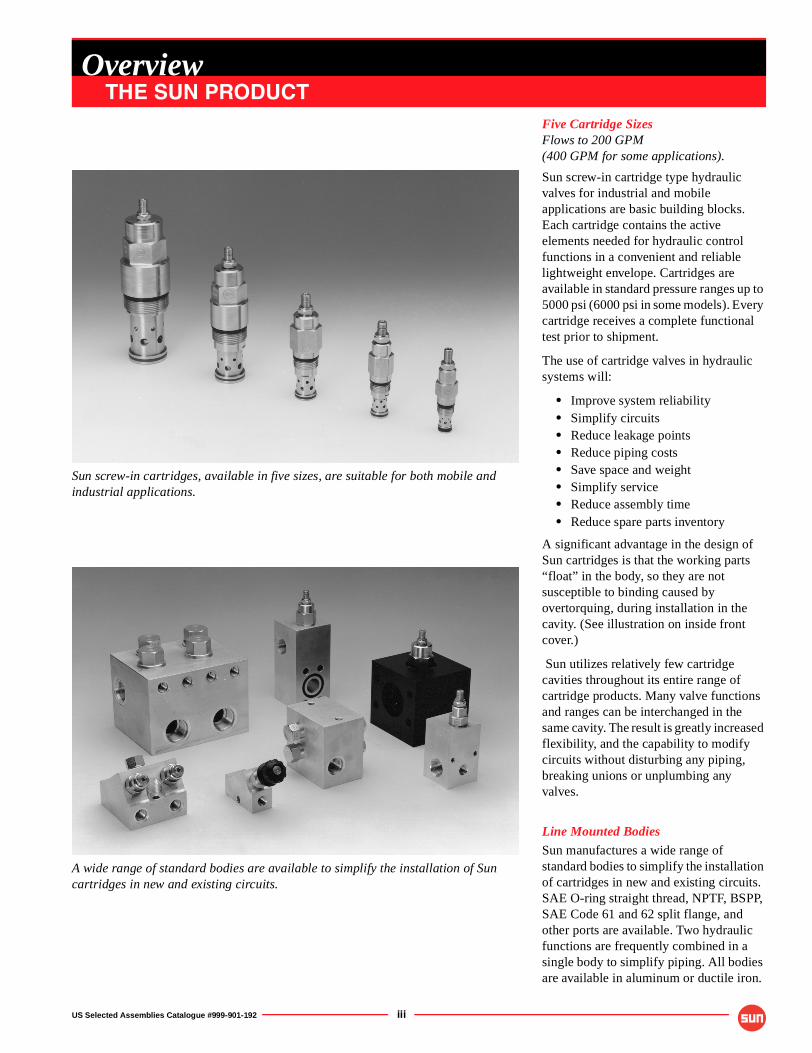
Sun screw-in cartridges, available in five sizes, are suitable for both mobile and industrial applications.
A wide range of standard bodies are available to simplify the installation of Sun cartridges in new and existing circuits.
Five Cartridge SizesFlows to 200 GPM(400 GPM for some applications).
Sun screw-in cartridge type hydraulic valves for industrial and mobile applications are basic building blocks. Each cartridge contains the active elements needed for hydraulic control functions in a convenient and reliable lightweight envelope. Cartridges are available in standard pressure ranges up to 5000 psi (6000 psi in some models). Every cartridge receives a complete functional test prior to shipment.
The use of cartridge valves in hydraulic systems will:
• Improve system reliability• Simplify circuits• Reduce leakage points• Reduce piping costs• Save space and weight• Simplify service• Reduce assembly time• Reduce spare parts inventory
A significant advantage in the design of Sun cartridges is that the working parts “float” in the body, so they are not susceptible to binding caused by overtorquing, during installation in the cavity. (See illustration on inside front cover.)
Sun utilizes relatively few cartridge cavities throughout its entire range of cartridge products. Many valve functions and ranges can be interchanged in the same cavity. The result is greatly increased flexibility, and the capability to modify circuits without disturbing any piping, breaking unions or unplumbing any valves.
Line Mounted Bodies
Sun manufactures a wide range of standard bodies to simplify the installation of cartridges in new and existing circuits. SAE O-ring straight thread, NPTF, BSPP, SAE Code 61 and 62 split flange, and other ports are available. Two hydraulic functions are frequently combined in a single body to simplify piping. All bodies are available in aluminum or ductile iron.
OverviewTHE SUN PRODUCT
iv US Selected Assemblies Catalogue #999-901-192
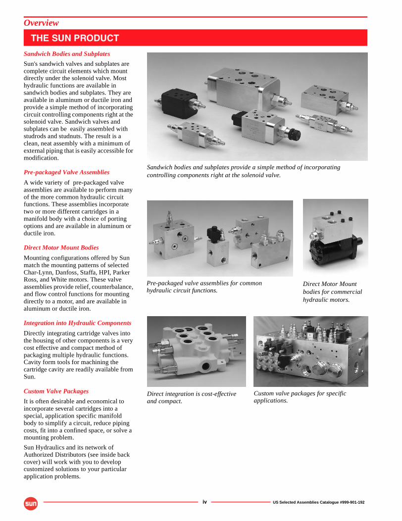
Sandwich Bodies and Subplates
Sun's sandwich valves and subplates are complete circuit elements which mount directly under the solenoid valve. Most hydraulic functions are available in sandwich bodies and subplates. They are available in aluminum or ductile iron and provide a simple method of incorporating circuit controlling components right at the solenoid valve. Sandwich valves and subplates can be easily assembled with studrods and studnuts. The result is a clean, neat assembly with a minimum of external piping that is easily accessible for modification.
Pre-packaged Valve Assemblies
A wide variety of pre-packaged valve assemblies are available to perform many of the more common hydraulic circuit functions. These assemblies incorporate two or more different cartridges in a manifold body with a choice of porting options and are available in aluminum or ductile iron.
Direct Motor Mount Bodies
Mounting configurations offered by Sun match the mounting patterns of selected Char-Lynn, Danfoss, Staffa, HPI, Parker Ross, and White motors. These valve assemblies provide relief, counterbalance, and flow control functions for mounting directly to a motor, and are available in aluminum or ductile iron.
Integration into Hydraulic Components
Directly integrating cartridge valves into the housing of other components is a very cost effective and compact method of packaging multiple hydraulic functions. Cavity form tools for machining the cartridge cavity are readily available from Sun.
Custom Valve Packages
It is often desirable and economical to incorporate several cartridges into a special, application specific manifold body to simplify a circuit, reduce piping costs, fit into a confined space, or solve a mounting problem.
Sun Hydraulics and its network of Authorized Distributors (see inside back cover) will work with you to develop customized solutions to your particular application problems.
Overview
THE SUN PRODUCT
Sandwich bodies and subplates provide a simple method of incorporating controlling components right at the solenoid valve.
Pre-packaged valve assemblies for common
Direct integration is cost-effectiveand compact.
hydraulic circuit functions.
Custom valve packages for specificapplications.
Direct Motor Mount bodies for commercial hydraulic motors.
US Selected Assemblies Catalogue #999-901-192 v
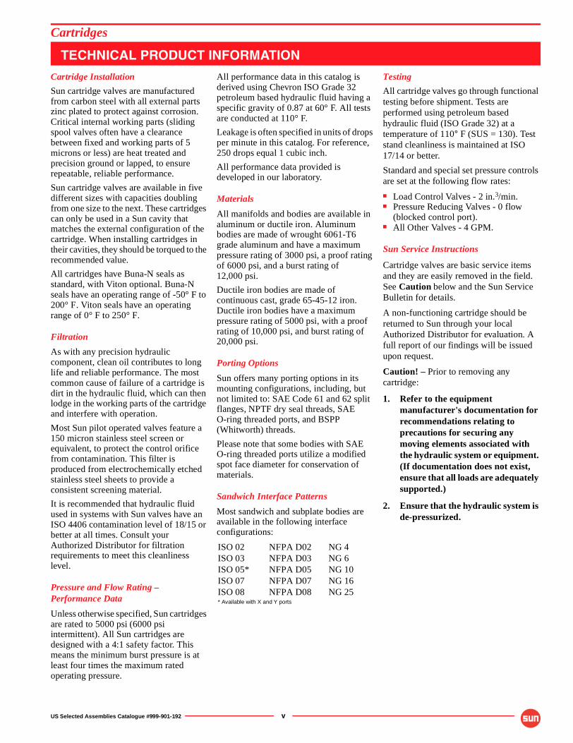
Cartridge Installation
Sun cartridge valves are manufactured from carbon steel with all external parts zinc plated to protect against corrosion. Critical internal working parts (sliding spool valves often have a clearance between fixed and working parts of 5 microns or less) are heat treated and precision ground or lapped, to ensure repeatable, reliable performance.
Sun cartridge valves are available in five different sizes with capacities doubling from one size to the next. These cartridges can only be used in a Sun cavity that matches the external configuration of the cartridge. When installing cartridges in their cavities, they should be torqued to the recommended value.
All cartridges have Buna-N seals as standard, with Viton optional. Buna-N seals have an operating range of -50° F to 200° F. Viton seals have an operating range of 0° F to 250° F.
Filtration
As with any precision hydraulic component, clean oil contributes to long life and reliable performance. The most common cause of failure of a cartridge is dirt in the hydraulic fluid, which can then lodge in the working parts of the cartridge and interfere with operation.
Most Sun pilot operated valves feature a 150 micron stainless steel screen or equivalent, to protect the control orifice from contamination. This filter is produced from electrochemically etched stainless steel sheets to provide a consistent screening material.
It is recommended that hydraulic fluid used in systems with Sun valves have an ISO 4406 contamination level of 18/15 or better at all times. Consult your Authorized Distributor for filtration requirements to meet this cleanliness level.
Pressure and Flow Rating –Performance Data
Unless otherwise specified, Sun cartridges are rated to 5000 psi (6000 psi intermittent). All Sun cartridges are designed with a 4:1 safety factor. This means the minimum burst pressure is at least four times the maximum rated operating pressure.
All performance data in this catalog is derived using Chevron ISO Grade 32 petroleum based hydraulic fluid having a specific gravity of 0.87 at 60° F. All tests are conducted at 110° F.
Leakage is often specified in units of drops per minute in this catalog. For reference, 250 drops equal 1 cubic inch.
All performance data provided is developed in our laboratory.
Materials
All manifolds and bodies are available in aluminum or ductile iron. Aluminum bodies are made of wrought 6061-T6 grade aluminum and have a maximum pressure rating of 3000 psi, a proof rating of 6000 psi, and a burst rating of 12,000 psi.
Ductile iron bodies are made of continuous cast, grade 65-45-12 iron. Ductile iron bodies have a maximum pressure rating of 5000 psi, with a proof rating of 10,000 psi, and burst rating of 20,000 psi.
Porting Options
Sun offers many porting options in its mounting configurations, including, but not limited to: SAE Code 61 and 62 split flanges, NPTF dry seal threads, SAE O-ring threaded ports, and BSPP (Whitworth) threads.
Please note that some bodies with SAE O-ring threaded ports utilize a modified spot face diameter for conservation of materials.
Sandwich Interface Patterns
Most sandwich and subplate bodies are available in the following interface configurations:
Testing
All cartridge valves go through functional testing before shipment. Tests are performed using petroleum based hydraulic fluid (ISO Grade 32) at a temperature of 110° F (SUS = 130). Test stand cleanliness is maintained at ISO 17/14 or better.
Standard and special set pressure controls are set at the following flow rates:
■ Load Control Valves - 2 in.3/min.■ Pressure Reducing Valves - 0 flow
(blocked control port).■ All Other Valves - 4 GPM.
Sun Service Instructions
Cartridge valves are basic service items and they are easily removed in the field. See Caution below and the Sun Service Bulletin for details.
A non-functioning cartridge should be returned to Sun through your local Authorized Distributor for evaluation. A full report of our findings will be issued upon request.
Caution! – Prior to removing any cartridge:
1. Refer to the equipment manufacturer's documentation for recommendations relating to precautions for securing any moving elements associated with the hydraulic system or equipment. (If documentation does not exist, ensure that all loads are adequately supported.)
2. Ensure that the hydraulic system is de-pressurized.
ISO 02 NFPA D02 NG 4ISO 03 NFPA D03 NG 6ISO 05* NFPA D05 NG 10ISO 07 NFPA D07 NG 16ISO 08 NFPA D08 NG 25* Available with X and Y ports
Cartridges
TECHNICAL PRODUCT INFORMATION
vi US Selected Assemblies Catalogue #999-901-192
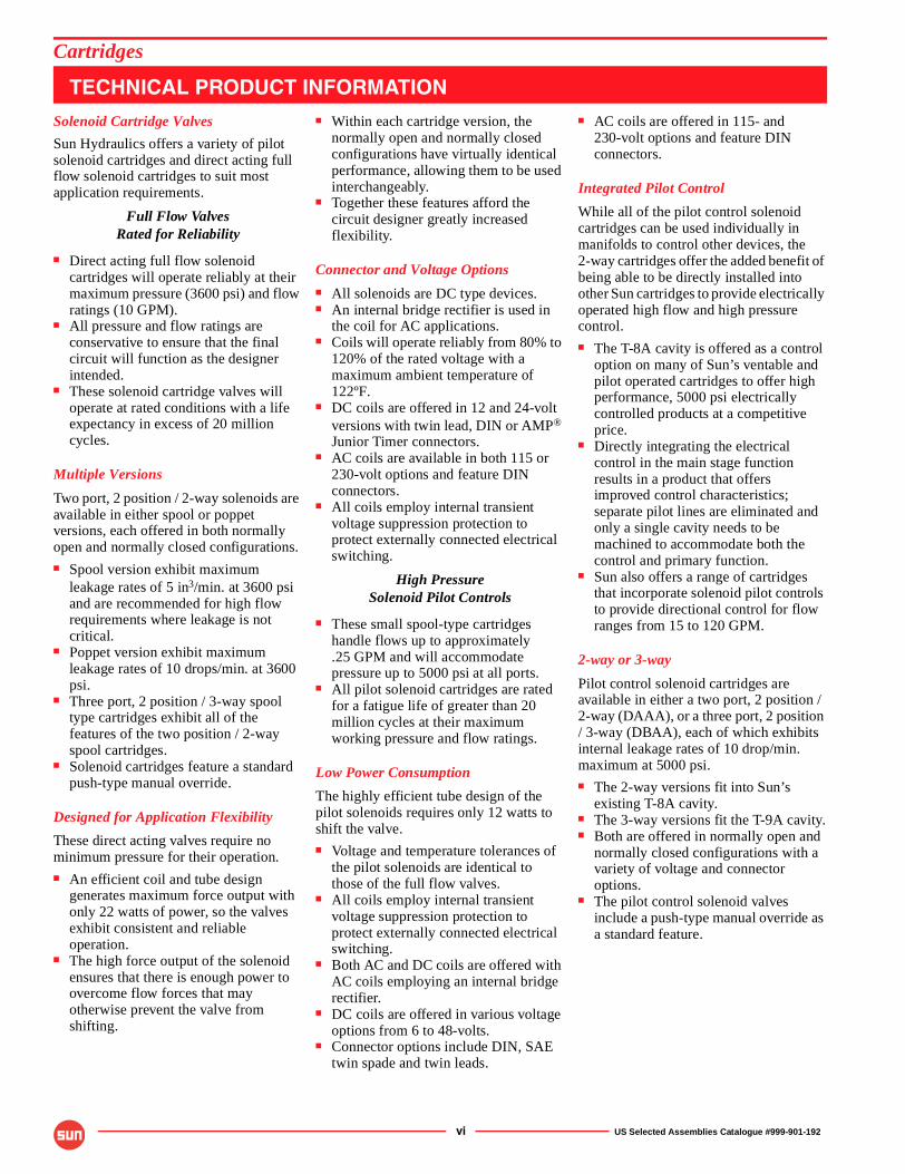
Solenoid Cartridge Valves
Sun Hydraulics offers a variety of pilot solenoid cartridges and direct acting full flow solenoid cartridges to suit most application requirements.
Full Flow ValvesRated for Reliability
■ Direct acting full flow solenoid cartridges will operate reliably at their maximum pressure (3600 psi) and flow ratings (10 GPM).
■ All pressure and flow ratings are conservative to ensure that the final circuit will function as the designer intended.
■ These solenoid cartridge valves will operate at rated conditions with a life expectancy in excess of 20 million cycles.
Multiple Versions
Two port, 2 position / 2-way solenoids are available in either spool or poppet versions, each offered in both normally open and normally closed configurations.■ Spool version exhibit maximum
leakage rates of 5 in3/min. at 3600 psi and are recommended for high flow requirements where leakage is not critical.
■ Poppet version exhibit maximum leakage rates of 10 drops/min. at 3600 psi.
■ Three port, 2 position / 3-way spool type cartridges exhibit all of the features of the two position / 2-way spool cartridges.
■ Solenoid cartridges feature a standard push-type manual override.
Designed for Application Flexibility
These direct acting valves require no minimum pressure for their operation.■ An efficient coil and tube design
generates maximum force output with only 22 watts of power, so the valves exhibit consistent and reliable operation.
■ The high force output of the solenoid ensures that there is enough power to overcome flow forces that may otherwise prevent the valve from shifting.
■ Within each cartridge version, the normally open and normally closed configurations have virtually identical performance, allowing them to be used interchangeably.
■ Together these features afford the circuit designer greatly increased flexibility.
Connector and Voltage Options■ All solenoids are DC type devices.■ An internal bridge rectifier is used in
the coil for AC applications.■ Coils will operate reliably from 80% to
120% of the rated voltage with a maximum ambient temperature of 122ºF.
■ DC coils are offered in 12 and 24-volt versions with twin lead, DIN or AMP® Junior Timer connectors.
■ AC coils are available in both 115 or 230-volt options and feature DIN connectors.
■ All coils employ internal transient voltage suppression protection to protect externally connected electrical switching.
High PressureSolenoid Pilot Controls
■ These small spool-type cartridges handle flows up to approximately.25 GPM and will accommodate pressure up to 5000 psi at all ports.
■ All pilot solenoid cartridges are rated for a fatigue life of greater than 20 million cycles at their maximum working pressure and flow ratings.
Low Power Consumption
The highly efficient tube design of the pilot solenoids requires only 12 watts to shift the valve.■ Voltage and temperature tolerances of
the pilot solenoids are identical to those of the full flow valves.
■ All coils employ internal transient voltage suppression protection to protect externally connected electrical switching.
■ Both AC and DC coils are offered with AC coils employing an internal bridge rectifier.
■ DC coils are offered in various voltage options from 6 to 48-volts.
■ Connector options include DIN, SAE twin spade and twin leads.
■ AC coils are offered in 115- and 230-volt options and feature DIN connectors.
Integrated Pilot Control
While all of the pilot control solenoid cartridges can be used individually in manifolds to control other devices, the 2-way cartridges offer the added benefit of being able to be directly installed into other Sun cartridges to provide electrically operated high flow and high pressure control.■ The T-8A cavity is offered as a control
option on many of Sun’s ventable and pilot operated cartridges to offer high performance, 5000 psi electrically controlled products at a competitive price.
■ Directly integrating the electrical control in the main stage function results in a product that offers improved control characteristics; separate pilot lines are eliminated and only a single cavity needs to be machined to accommodate both the control and primary function.
■ Sun also offers a range of cartridges that incorporate solenoid pilot controls to provide directional control for flow ranges from 15 to 120 GPM.
2-way or 3-way
Pilot control solenoid cartridges are available in either a two port, 2 position / 2-way (DAAA), or a three port, 2 position / 3-way (DBAA), each of which exhibits internal leakage rates of 10 drop/min. maximum at 5000 psi.■ The 2-way versions fit into Sun’s
existing T-8A cavity.■ The 3-way versions fit the T-9A cavity.■ Both are offered in normally open and
normally closed configurations with a variety of voltage and connector options.
■ The pilot control solenoid valves include a push-type manual override as a standard feature.
Cartridges
TECHNICAL PRODUCT INFORMATION
US Selected Assemblies Catalogue #999-901-192 vii
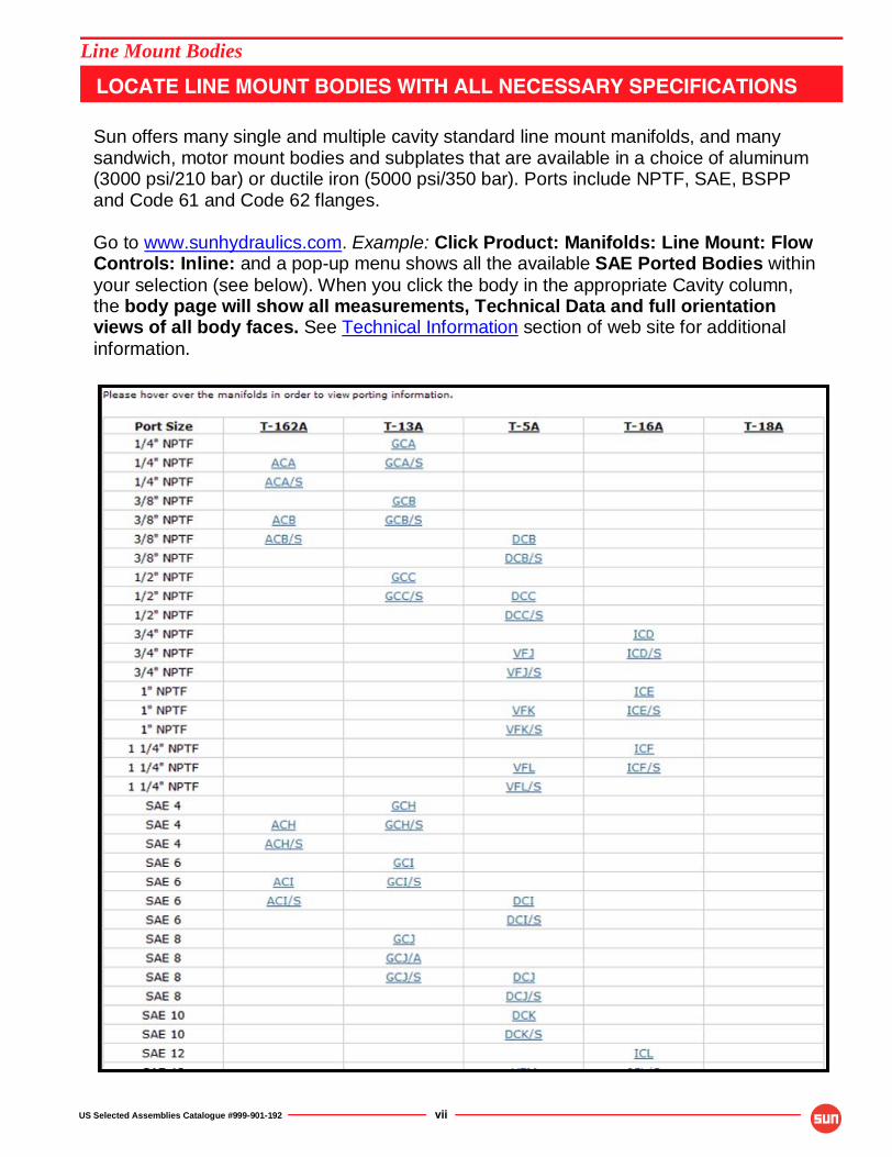
Line Mount Bodies
LOCATE LINE MOUNT BODIES WITH ALL NECESSARY SPECIFICATIONS Sun offers many single and multiple cavity standard line mount manifolds, and many sandwich, motor mount bodies and subplates that are available in a choice of aluminum (3000 psi/210 bar) or ductile iron (5000 psi/350 bar). Ports include NPTF, SAE, BSPP and Code 61 and Code 62 flanges. Go to www.sunhydraulics.com. Example: Click Product: Manifolds: Line Mount: Flow Controls: Inline: and a pop-up menu shows all the available SAE Ported Bodies within your selection (see below). When you click the body in the appropriate Cavity column, the body page will show all measurements, Technical Data and full orientation views of all body faces. See Technical Information section of web site for additional information.
viii US Selected Assemblies Catalogue #999-901-192
NOTES
US Selected Assemblies Catalogue #999-901-192 1
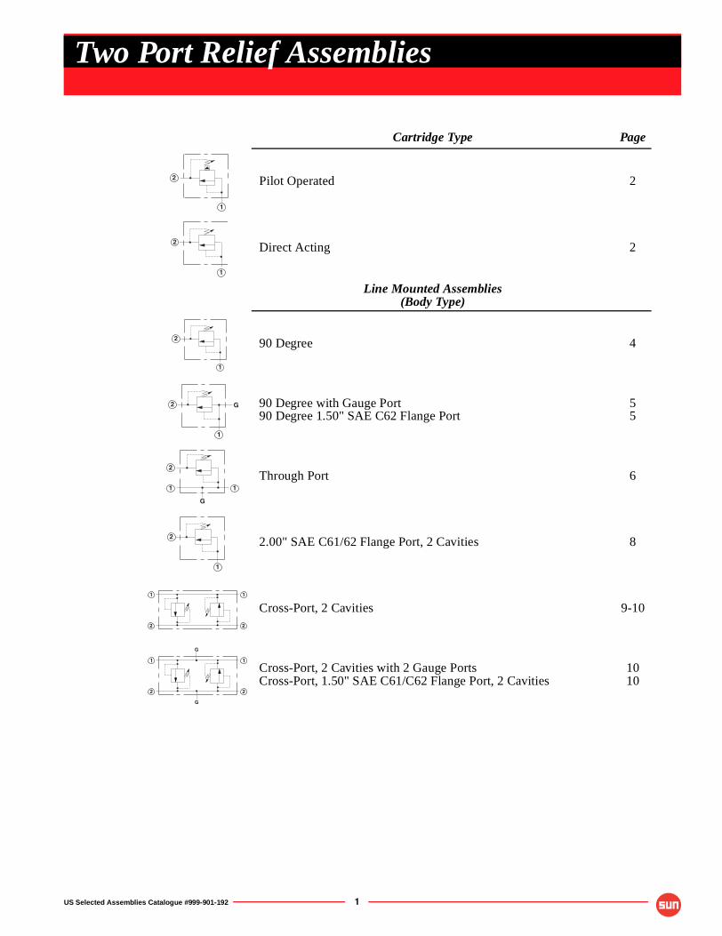
Cartridge Type Page
Pilot Operated 2
Direct Acting 2
Line Mounted Assemblies(Body Type)
90 Degree 4
90 Degree with Gauge Port90 Degree 1.50" SAE C62 Flange Port
55
Through Port 6
2.00" SAE C61/62 Flange Port, 2 Cavities 8
Cross-Port, 2 Cavities 9-10
Cross-Port, 2 Cavities with 2 Gauge PortsCross-Port, 1.50" SAE C61/C62 Flange Port, 2 Cavities
1010
2
1
2
1
2
1
2
1
G
2
11
G
2
1
�
�
�
�
�
�
�
�
�
�
Two Port Relief Assemblies
OPTION ORDERING INFORMATION
OPTION ORDERING INFORMATION
2 US Selected Assemblies Catalogue #999-901-192
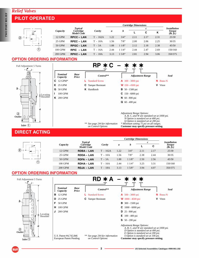
Relief Valves
PILOT OPERATED
RP ✱ C – ✱ ✱ ✱
Nominal Base Control** Adjustment Range SealCapacity Price
C 12 GPM* L Standard Screw A 100 - 3000 psi N Buna-N
E 25 GPM C Tamper Resistant W 150 - 4500 psi V Viton
G 50 GPM K Handknob B 50 - 1500 psi
I 100 GPM C 150 - 6000 psi
K 200 GPM N 60 - 800 psi
Q 60 - 400 psi
Adjustment Range Options:A, B, C, and W are standard set at 1000 psi.N Option is standard set at 400 psi.Q Option is standard set at 200 psi.
** See page 244 for information * Minimum setting 75 psi on all ranges.on Control Options Customer may specify pressure setting.
DIRECT ACTING
RD ✱ A – ✱ ✱ ✱
Nominal Base Control** Adjustment Range SealCapacity Price
B 12 GPM L Standard Screw A 500 - 3000 psi N Buna-N
D 25 GPM C Tamper Resistant W 1000 - 4500 psi V Viton
F 50 GPM B 300 - 1500 psi
H 100 GPM C 1000 - 6000 psi
J 200 GPM D 25 - 800 psi
E 100 - 400 psi
S 50 - 200 psi
Adjustment Range Options:A, B, C, and W are standard set at 1000 psi.D Option is standard set at 400 psi.E Option is standard set at 200 psi.
U.S. Patent #4,742,846 ** See page 244 for information S Option is standard set at 100 psi.European Patent Pending on Control Options Customer may specify pressure setting.
Cartridge Dimensions
CapacityTypical
CartridgeModel Code
Cavity a bc Installation
Torque(lb. ft.)L C K
12 GPM RPCC – LAN T - 162A 1.22 3/4” 2.11 2.17 2.31 25/30
25 GPM RPEC – LAN T - 10A 1.56 7/8” 2.00 2.06 2.25 30/35
50 GPM RPGC – LAN T - 3A 1.88 1 1/8” 2.12 2.18 2.38 45/50
100 GPM RPIC – LAN T - 16A 2.44 1 1/4” 2.44 2.47 2.69 150/160
200 GPM RPKC – LAN T - 18A 3.13 1 5/8” 2.81 2.94 3.06 350/375
Cartridge Dimensions
CapacityTypical
CartridgeModel Code
Cavity a bc Installation
Torque(lb. ft.)L C
12 GPM RDBA – LAN T - 162A 1.22 3/4” 2.11 2.17 25/30
25 GPM RDDA – LAN T - 10A 1.56 7/8” 2.38 2.44 30/35
50 GPM RDFA – LAN T - 3A 1.88 1 1/8” 2.50 2.56 45/50
100 GPM RDHA – LAN T - 16A 2.44 1 1/4” 3.25 3.31 150/160
200 GPM RDJA – LAN T - 18A 3.13 1 5/8” 3.94 4.07 350/375
2
1
Outlet
Inlet
c
a
LocatingShoulder
Full Adjustment 5 Turns
b
-+
2
1
2
1
Inlet
b
2
1
c
a
LocatingShoulder
Full Adjustment 5 Turns
Outlet
-+
TW
O P
OR
T R
EL
IEF
TECHNICAL TIPS / PERFORMANCE CURVES
US Selected Assemblies Catalogue #999-901-192 3
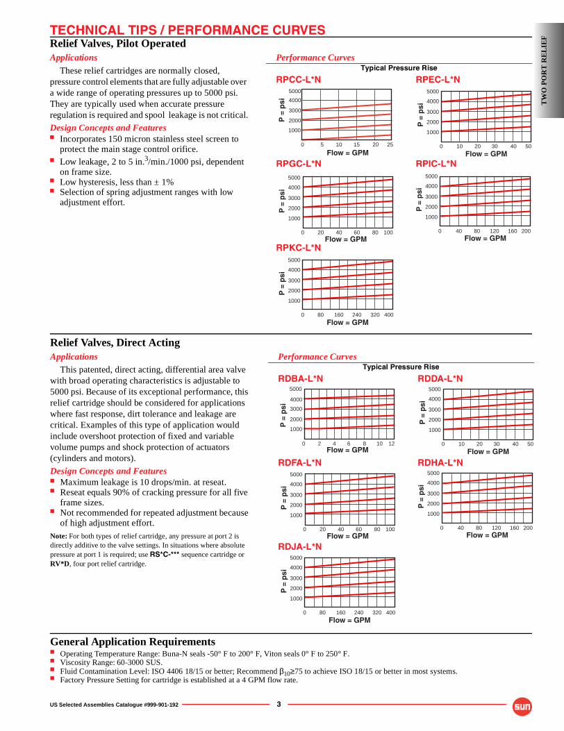
Relief Valves, Pilot OperatedApplications
These relief cartridges are normally closed, pressure control elements that are fully adjustable over a wide range of operating pressures up to 5000 psi. They are typically used when accurate pressure regulation is required and spool leakage is not critical.
Design Concepts and Features■ Incorporates 150 micron stainless steel screen to
protect the main stage control orifice.■ Low leakage, 2 to 5 in.3/min./1000 psi, dependent
on frame size.■ Low hysteresis, less than ± 1%■ Selection of spring adjustment ranges with low
adjustment effort.
Performance CurvesTypical Pressure Rise
RPCC-L*N RPEC-L*N
RPGC-L*N RPIC-L*N
RPKC-L*N
320 80 160 240
Flow = GPM400
P =
psi
0
2000
3000
4000
5000
1000
10080 20 40 60Flow = GPM
P =
psi
0
2000
3000
4000
5000
1000
160 40 80 120Flow = GPM
200
P =
psi
0
2000
3000
4000
5000
1000
255 10 150
5000
4000
3000
2000
1000
20
Flow = GPM
P =
psi
5040 10 20 30
Flow = GPM
P =
psi
0
2000
3000
4000
5000
1000
TW
O P
OR
T R
EL
IEF
Relief Valves, Direct ActingApplications
This patented, direct acting, differential area valve with broad operating characteristics is adjustable to 5000 psi. Because of its exceptional performance, this relief cartridge should be considered for applications where fast response, dirt tolerance and leakage are critical. Examples of this type of application would include overshoot protection of fixed and variable volume pumps and shock protection of actuators (cylinders and motors).
Design Concepts and Features■ Maximum leakage is 10 drops/min. at reseat.■ Reseat equals 90% of cracking pressure for all five
frame sizes.■ Not recommended for repeated adjustment because
of high adjustment effort.Note: For both types of relief cartridge, any pressure at port 2 is directly additive to the valve settings. In situations where absolute pressure at port 1 is required; use RS*C-*** sequence cartridge or RV*D, four port relief cartridge.
Performance CurvesTypical Pressure Rise
RDBA-L*N RDDA-L*N
RDFA-L*N RDHA-L*N
RDJA-L*N
320 80 160 240
Flow = GPM400
P =
psi
0
2000
3000
4000
5000
1000
10080 20 40 60Flow = GPM
P =
psi
0
2000
3000
4000
5000
1000
160 40 80 120Flow = GPM
200
P =
psi
0
2000
3000
4000
5000
1000
0 8 2 4 6Flow = GPM
P =
psi
5000
4000
3000
2000
1000
10 12 5040 10 20 30
Flow = GPM
P =
psi
0
2000
3000
4000
5000
1000
General Application Requirements■ Operating Temperature Range: Buna-N seals -50° F to 200° F, Viton seals 0° F to 250° F.■ Viscosity Range: 60-3000 SUS.■ Fluid Contamination Level: ISO 4406 18/15 or better; Recommend β10≥75 to achieve ISO 18/15 or better in most systems.■ Factory Pressure Setting for cartridge is established at a 4 GPM flow rate.
4 US Selected Assemblies Catalogue #999-901-192
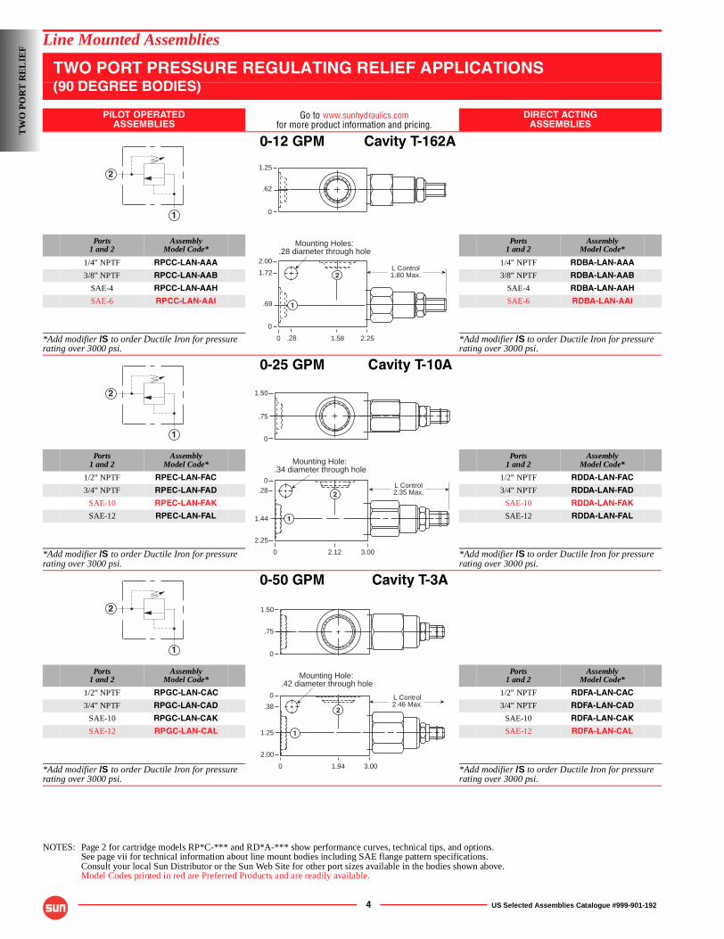
Line Mounted Assemblies
TWO PORT PRESSURE REGULATING RELIEF APPLICATIONS(90 DEGREE BODIES)
PILOT OPERATEDASSEMBLIES
Go to www.sunhydraulics.comfor more product information and pricing.
DIRECT ACTINGASSEMBLIES
0-12 GPM Cavity T-162A
Ports1 and 2
AssemblyModel Code*
Ports1 and 2
AssemblyModel Code*
1/4” NPTF RPCC-LAN-AAA 1/4” NPTF RDBA-LAN-AAA
3/8” NPTF RPCC-LAN-AAB 3/8” NPTF RDBA-LAN-AAB
SAE-4 RPCC-LAN-AAH SAE-4 RDBA-LAN-AAH
SAE-6 RPCC-LAN-AAI SAE-6 RDBA-LAN-AAI
*Add modifier /S to order Ductile Iron for pressure rating over 3000 psi.
*Add modifier /S to order Ductile Iron for pressure rating over 3000 psi.
0-25 GPM Cavity T-10A
Ports1 and 2
AssemblyModel Code*
Ports1 and 2
AssemblyModel Code*
1/2” NPTF RPEC-LAN-FAC 1/2” NPTF RDDA-LAN-FAC
3/4” NPTF RPEC-LAN-FAD 3/4” NPTF RDDA-LAN-FAD
SAE-10 RPEC-LAN-FAK SAE-10 RDDA-LAN-FAK
SAE-12 RPEC-LAN-FAL SAE-12 RDDA-LAN-FAL
*Add modifier /S to order Ductile Iron for pressure rating over 3000 psi.
*Add modifier /S to order Ductile Iron for pressure rating over 3000 psi.
0-50 GPM Cavity T-3A
Ports1 and 2
AssemblyModel Code*
Ports1 and 2
AssemblyModel Code*
1/2” NPTF RPGC-LAN-CAC 1/2” NPTF RDFA-LAN-CAC
3/4” NPTF RPGC-LAN-CAD 3/4” NPTF RDFA-LAN-CAD
SAE-10 RPGC-LAN-CAK SAE-10 RDFA-LAN-CAK
SAE-12 RPGC-LAN-CAL SAE-12 RDFA-LAN-CAL
*Add modifier /S to order Ductile Iron for pressure rating over 3000 psi.
*Add modifier /S to order Ductile Iron for pressure rating over 3000 psi.
NOTES: Page 2 for cartridge models RP*C-*** and RD*A-*** show performance curves, technical tips, and options.See page vii for technical information about line mount bodies including SAE flange pattern specifications.Consult your local Sun Distributor or the Sun Web Site for other port sizes available in the bodies shown above.Model Codes printed in red are Preferred Products and are readily available.
2
1
Mounting Holes:.28 diameter through hole
0
2.00
1.72
.69
0
2.251.58
L Control1.80 Max.
1.25
.62
0
.28
1
2
2
1
Mounting Hole:.34 diameter through hole
1.50
0
.75
0 2.12 3.00
2.25
.280
1.44
L Control2.35 Max.
1
2
2
1
Mounting Hole:.42 diameter through hole
0
1.50
.75
0
.38
1.25
2.00
0 3.001.94
1
2
L Control2.46 Max.
TW
O P
OR
T R
EL
IEF
US Selected Assemblies Catalogue #999-901-192 5
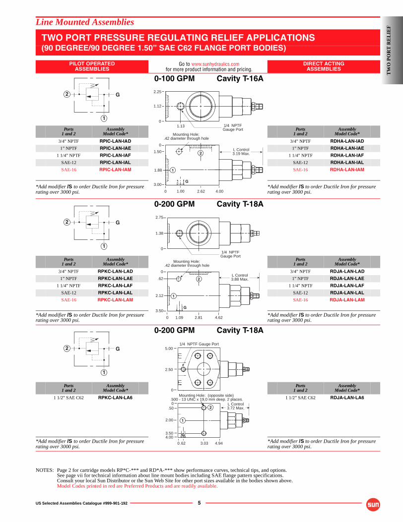
Line Mounted Assemblies
TWO PORT PRESSURE REGULATING RELIEF APPLICATIONS(90 DEGREE/90 DEGREE 1.50” SAE C62 FLANGE PORT BODIES)
PILOT OPERATEDASSEMBLIES
Go to www.sunhydraulics.comfor more product information and pricing.
DIRECT ACTINGASSEMBLIES
0-100 GPM Cavity T-16A
Ports1 and 2
AssemblyModel Code*
Ports1 and 2
AssemblyModel Code*
3/4” NPTF RPIC-LAN-IAD 3/4” NPTF RDHA-LAN-IAD
1” NPTF RPIC-LAN-IAE 1” NPTF RDHA-LAN-IAE
1 1/4” NPTF RPIC-LAN-IAF 1 1/4” NPTF RDHA-LAN-IAF
SAE-12 RPIC-LAN-IAL SAE-12 RDHA-LAN-IAL
SAE-16 RPIC-LAN-IAM SAE-16 RDHA-LAN-IAM
*Add modifier /S to order Ductile Iron for pressure rating over 3000 psi.
*Add modifier /S to order Ductile Iron for pressure rating over 3000 psi.
0-200 GPM Cavity T-18A
Ports1 and 2
AssemblyModel Code*
Ports1 and 2
AssemblyModel Code*
3/4” NPTF RPKC-LAN-LAD 3/4” NPTF RDJA-LAN-LAD
1” NPTF RPKC-LAN-LAE 1” NPTF RDJA-LAN-LAE
1 1/4” NPTF RPKC-LAN-LAF 1 1/4” NPTF RDJA-LAN-LAF
SAE-12 RPKC-LAN-LAL SAE-12 RDJA-LAN-LAL
SAE-16 RPKC-LAN-LAM SAE-16 RDJA-LAN-LAM
*Add modifier /S to order Ductile Iron for pressure rating over 3000 psi.
*Add modifier /S to order Ductile Iron for pressure rating over 3000 psi.
0-200 GPM Cavity T-18A
Ports1 and 2
AssemblyModel Code*
Ports1 and 2
AssemblyModel Code*
1 1/2” SAE C62 RPKC-LAN-LA6 1 1/2” SAE C62 RDJA-LAN-LA6
*Add modifier /S to order Ductile Iron for pressure rating over 3000 psi.
*Add modifier /S to order Ductile Iron for pressure rating over 3000 psi.
NOTES: Page 2 for cartridge models RP*C-*** and RD*A-*** show performance curves, technical tips, and options.See page vii for technical information about line mount bodies including SAE flange pattern specifications.Consult your local Sun Distributor or the Sun Web Site for other port sizes available in the bodies shown above.Model Codes printed in red are Preferred Products and are readily available.
2
1
G
Mounting Hole:.42 diameter through hole
0
2.25
1.12
1.13
0
1.50
1.88
3.00G
1
0 4.002.621.00
L Control3.19 Max.
1/4 NPTFGauge Port
2
2
1
G2.75
0
1.38
1/4 NPTFGauge Port
Mounting Hole:.42 diameter through hole
3.50
.62
0
2.12
0 2.81 4.621.09
G
L Control3.88 Max.2
1
2
1
G
Mounting Hole: (opposite side).500 - 13 UNC x 19,0 mm deep. 2 places.
L Control3.72 Max..50
0
2.00
3.504.00
.62 3.03 4.940
G
1
2
1/4 NPTF Gauge Port5.00
2.50
0T
WO
PO
RT
RE
LIE
F
6 US Selected Assemblies Catalogue #999-901-192
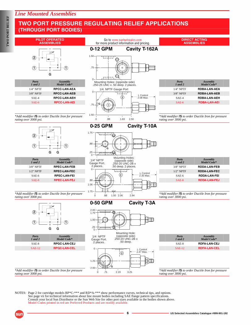
Line Mounted Assemblies
TWO PORT PRESSURE REGULATING RELIEF APPLICATIONS(THROUGH PORT BODIES)
PILOT OPERATEDASSEMBLIES
Go to www.sunhydraulics.comfor more product information and pricing.
DIRECT ACTINGASSEMBLIES
0-12 GPM Cavity T-162A
Ports1 and 2
AssemblyModel Code*
Ports1 and 2
AssemblyModel Code*
1/4” NPTF RPCC-LAN-AEA 1/4” NPTF RDBA-LAN-AEA
3/8” NPTF RPCC-LAN-AEB 3/8” NPTF RDBA-LAN-AEB
SAE-4 RPCC-LAN-AEH SAE-4 RDBA-LAN-AEH
SAE-6 RPCC-LAN-AEI SAE-6 RDBA-LAN-AEI
*Add modifier /S to order Ductile Iron for pressure rating over 3000 psi.
*Add modifier /S to order Ductile Iron for pressure rating over 3000 psi.
0-25 GPM Cavity T-10A
Ports1 and 2
AssemblyModel Code*
Ports1 and 2
AssemblyModel Code*
3/8” NPTF RPEC-LAN-FEB 3/8” NPTF RDDA-LAN-FEB
1/2” NPTF RPEC-LAN-FEC 1/2” NPTF RDDA-LAN-FEC
SAE-6 RPEC-LAN-FEI SAE-6 RDDA-LAN-FEI
SAE-8 RPEC-LAN-FEJ SAE-8 RDDA-LAN-FEJ
*Add modifier /S to order Ductile Iron for pressure rating over 3000 psi.
*Add modifier /S to order Ductile Iron for pressure rating over 3000 psi.
0-50 GPM Cavity T-3A
Ports1 and 2
AssemblyModel Code*
Ports1 and 2
AssemblyModel Code*
SAE-8 RPGC-LAN-CEJ SAE-8 RDFA-LAN-CEJ
SAE-12 RPGC-LAN-CEL SAE-12 RDFA-LAN-CEL
*Add modifier /S to order Ductile Iron for pressure rating over 3000 psi.
*Add modifier /S to order Ductile Iron for pressure rating over 3000 psi.
NOTES: Page 2 for cartridge models RP*C-*** and RD*A-*** show performance curves, technical tips, and options.See page vii for technical information about line mount bodies including SAE flange pattern specifications.Consult your local Sun Distributor or the Sun Web Site for other port sizes available in the bodies shown above.Model Codes printed in red are Preferred Products and are readily available.
2
11
G
L Control2.08 Max.
0
0
.75
1.50
2.501.83.88
1.50
.75
0Mounting Holes: (opposite side)
.250-25 UNC x .50 deep. 2 places.
1/4 NPTF Gauge Port
2
1G
2
11
G G0
Mounting Holes:(opposite side)
.250-20 UNC-2B x.50 deep. 2 places.
0
.88
1.06
1.75
0 2.941.50 2.06.88
L Control2.35 Max.
1.75
.88
2
.25
1
G
1/4” NPTFGauge Port.
2 places.
2
11
G GMounting Hole:(opposite side)
.250-20 UNC-2B x.50 deep.
0
2.00
1.00
1.75
.25
1/4 NPTFGauge Port.
2 places.
0
1.25
2.00 G
2
0 3.252.19.75
1
L Control2.47 Max.
TW
O P
OR
T R
EL
IEF
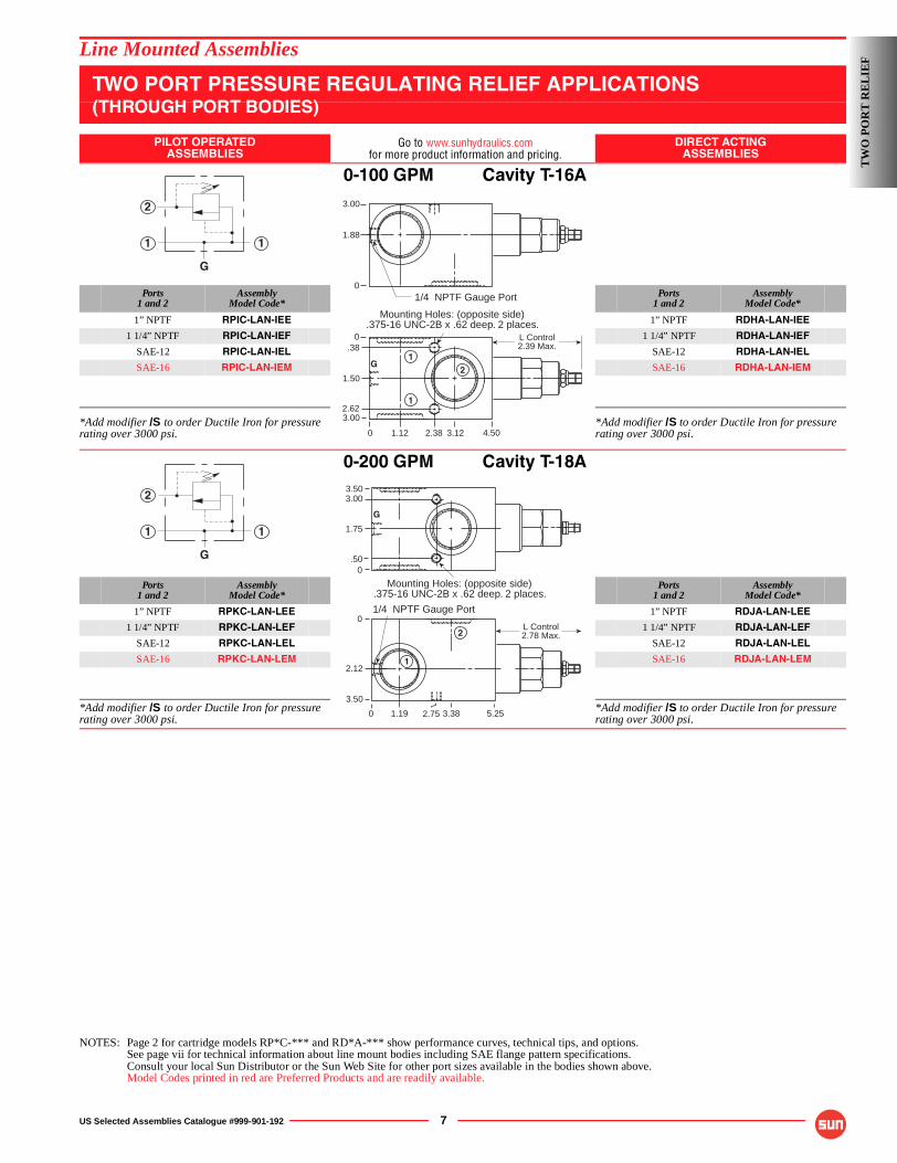
US Selected Assemblies Catalogue #999-901-192 7
Line Mounted Assemblies
TWO PORT PRESSURE REGULATING RELIEF APPLICATIONS(THROUGH PORT BODIES)
PILOT OPERATEDASSEMBLIES
Go to www.sunhydraulics.comfor more product information and pricing.
DIRECT ACTINGASSEMBLIES
0-100 GPM Cavity T-16A
Ports1 and 2
AssemblyModel Code*
Ports1 and 2
AssemblyModel Code*
1” NPTF RPIC-LAN-IEE 1” NPTF RDHA-LAN-IEE
1 1/4” NPTF RPIC-LAN-IEF 1 1/4” NPTF RDHA-LAN-IEF
SAE-12 RPIC-LAN-IEL SAE-12 RDHA-LAN-IEL
SAE-16 RPIC-LAN-IEM SAE-16 RDHA-LAN-IEM
*Add modifier /S to order Ductile Iron for pressure rating over 3000 psi.
*Add modifier /S to order Ductile Iron for pressure rating over 3000 psi.
0-200 GPM Cavity T-18A
Ports1 and 2
AssemblyModel Code*
Ports1 and 2
AssemblyModel Code*
1” NPTF RPKC-LAN-LEE 1” NPTF RDJA-LAN-LEE
1 1/4” NPTF RPKC-LAN-LEF 1 1/4” NPTF RDJA-LAN-LEF
SAE-12 RPKC-LAN-LEL SAE-12 RDJA-LAN-LEL
SAE-16 RPKC-LAN-LEM SAE-16 RDJA-LAN-LEM
*Add modifier /S to order Ductile Iron for pressure rating over 3000 psi.
*Add modifier /S to order Ductile Iron for pressure rating over 3000 psi.
NOTES: Page 2 for cartridge models RP*C-*** and RD*A-*** show performance curves, technical tips, and options.See page vii for technical information about line mount bodies including SAE flange pattern specifications.Consult your local Sun Distributor or the Sun Web Site for other port sizes available in the bodies shown above.Model Codes printed in red are Preferred Products and are readily available.
2
11
G
Mounting Holes: (opposite side).375-16 UNC-2B x .62 deep. 2 places.
3.00
.380
1.50
0 2.38 3.121.12
2.62
4.50
3.00
0
1.88
1/4 NPTF Gauge Port
G1
2
1
L Control2.39 Max.
2
11
G
Mounting Holes: (opposite side).375-16 UNC-2B x .62 deep. 2 places.
0
0
2.12
3.50
0 5.253.381.19
L Control2.78 Max.
3.503.00
1.75
.50
1/4 NPTF Gauge Port
G
2
1
2.75
TW
O P
OR
T R
EL
IEF
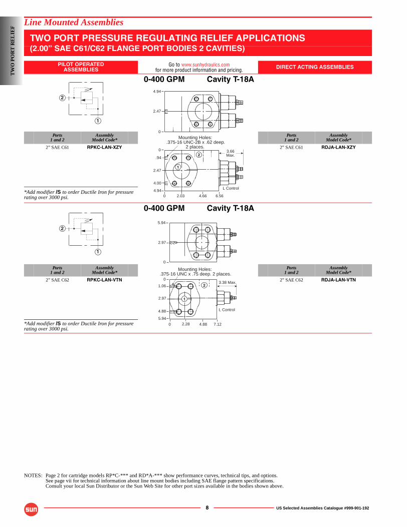
8 US Selected Assemblies Catalogue #999-901-192
Line Mounted Assemblies
TWO PORT PRESSURE REGULATING RELIEF APPLICATIONS(2.00” SAE C61/C62 FLANGE PORT BODIES 2 CAVITIES)
PILOT OPERATEDASSEMBLIES
Go to www.sunhydraulics.comfor more product information and pricing. DIRECT ACTING ASSEMBLIES
0-400 GPM Cavity T-18A
Ports1 and 2
AssemblyModel Code*
Ports1 and 2
AssemblyModel Code*
2” SAE C61 RPKC-LAN-XZY 2” SAE C61 RDJA-LAN-XZY
*Add modifier /S to order Ductile Iron for pressure rating over 3000 psi.
0-400 GPM Cavity T-18A
Ports1 and 2
AssemblyModel Code*
Ports1 and 2
AssemblyModel Code*
2” SAE C62 RPKC-LAN-VTN 2” SAE C62 RDJA-LAN-VTN
*Add modifier /S to order Ductile Iron for pressure rating over 3000 psi.
NOTES: Page 2 for cartridge models RP*C-*** and RD*A-*** show performance curves, technical tips, and options.See page vii for technical information about line mount bodies including SAE flange pattern specifications.Consult your local Sun Distributor or the Sun Web Site for other port sizes available in the bodies shown above.
2
1
Mounting Holes:.375-16 UNC-2B x .62 deep.
2 places.
0
4.94
2.47
0
2.47
.94
4.00
4.940 6.564.662.03
L Control
3.66Max.2
1
2
1
3.38 Max.
L Control
5.94
2.97
0
0
0
1.06
2.97
5.94
7.124.882.28
4.88
1
Mounting Holes:.375-16 UNC x .75 deep. 2 places.
2
TW
O P
OR
T R
EL
IEF
US Selected Assemblies Catalogue #999-901-192 9
Line Mounted Assemblies
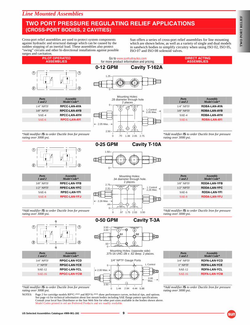
TWO PORT PRESSURE REGULATING RELIEF APPLICATIONS(CROSS-PORT BODIES, 2 CAVITIES)
Cross-port relief assemblies are used to protect system components against hydraulic and structural damage which can be caused by the sudden stopping of an inertial load. These assemblies also protect “swing” circuits and other bi-directional installations against possible surges and cavitation.
Sun offers a series of cross-port relief assemblies for line mounting which are shown below, as well as a variety of single and dual models in sandwich bodies to simplify circuitry when using ISO 02, ISO 05, ISO 07 and ISO 08 solenoid valves.
PILOT OPERATEDASSEMBLIES
Go to www.sunhydraulics.comfor more product information and pricing.
DIRECT ACTINGASSEMBLIES
0-12 GPM Cavity T-162A
Ports1 and 2
AssemblyModel Code*
Ports1 and 2
AssemblyModel Code*
1/4” NPTF RPCC-LAN-AYA 1/4” NPTF RDBA-LAN-AYA
3/8” NPTF RPCC-LAN-AYB 3/8” NPTF RDBA-LAN-AYB
SAE-4 RPCC-LAN-AYH SAE-4 RDBA-LAN-AYH
SAE-6 RPCC-LAN-AYI SAE-6 RDBA-LAN-AYI
*Add modifier /S to order Ductile Iron for pressure rating over 3000 psi.
*Add modifier /S to order Ductile Iron for pressure rating over 3000 psi.
0-25 GPM Cavity T-10A
Ports1 and 2
AssemblyModel Code*
Ports1 and 2
AssemblyModel Code*
3/8” NPTF RPEC-LAN-YFB 3/8” NPTF RDDA-LAN-YFB
1/2” NPTF RPEC-LAN-YFC 1/2” NPTF RDDA-LAN-YFC
SAE-6 RPEC-LAN-YFI SAE-6 RDDA-LAN-YFI
SAE-8 RPEC-LAN-YFJ SAE-8 RDDA-LAN-YFJ
*Add modifier /S to order Ductile Iron for pressure rating over 3000 psi.
*Add modifier /S to order Ductile Iron for pressure rating over 3000 psi.
0-50 GPM Cavity T-3A
Ports1 and 2
AssemblyModel Code*
Ports1 and 2
AssemblyModel Code*
3/4” NPTF RPGC-LAN-YCD 3/4” NPTF RDFA-LAN-YCD
1” NPTF RPGC-LAN-YCE 1” NPTF RDFA-LAN-YCE
SAE-12 RPGC-LAN-YCL SAE-12 RDFA-LAN-YCL
SAE-16 RPGC-LAN-YCM SAE-16 RDFA-LAN-YCM
*Add modifier /S to order Ductile Iron for pressure rating over 3000 psi.
*Add modifier /S to order Ductile Iron for pressure rating over 3000 psi.
NOTES: Page 2 for cartridge models RP*C-*** and RD*A-*** show performance curves, technical tips, and options.See page vii for technical information about line mount bodies including SAE flange pattern specifications.Consult your local Sun Distributor or the Sun Web Site for other port sizes available in the bodies shown above.Model Codes printed in red are Preferred Products and are readily available.
�
�
�
�
Mounting Holes:.28 diameter through hole
2 places
1.25
0
1.380
0
2.50
2.752.05.70
L Control2.05 Max.
1 2
21
2.05 Max.
�
�
�
�
Mounting Holes:.34 diameter through hole.
2 places.
1.50
0
0 3.50
2.75
2.31
.44
0
2.531.75.97
L Control2.26 Max.1 2
1 22.26 Max.
�
�
�
�
�
�
Mounting Holes: (opposite side).375-16 UNC-2B x .62 deep. 2 places.
0
3.503.00
.50
21
21
G1 G2
0
0
3.50
4.44 5.882.941.44
2.00Max.
L Control
1/4” NPTF Gauge Ports
2.00 Max.
TW
O P
OR
T R
EL
IEF
10 US Selected Assemblies Catalogue #999-901-192
Line Mounted Assemblies
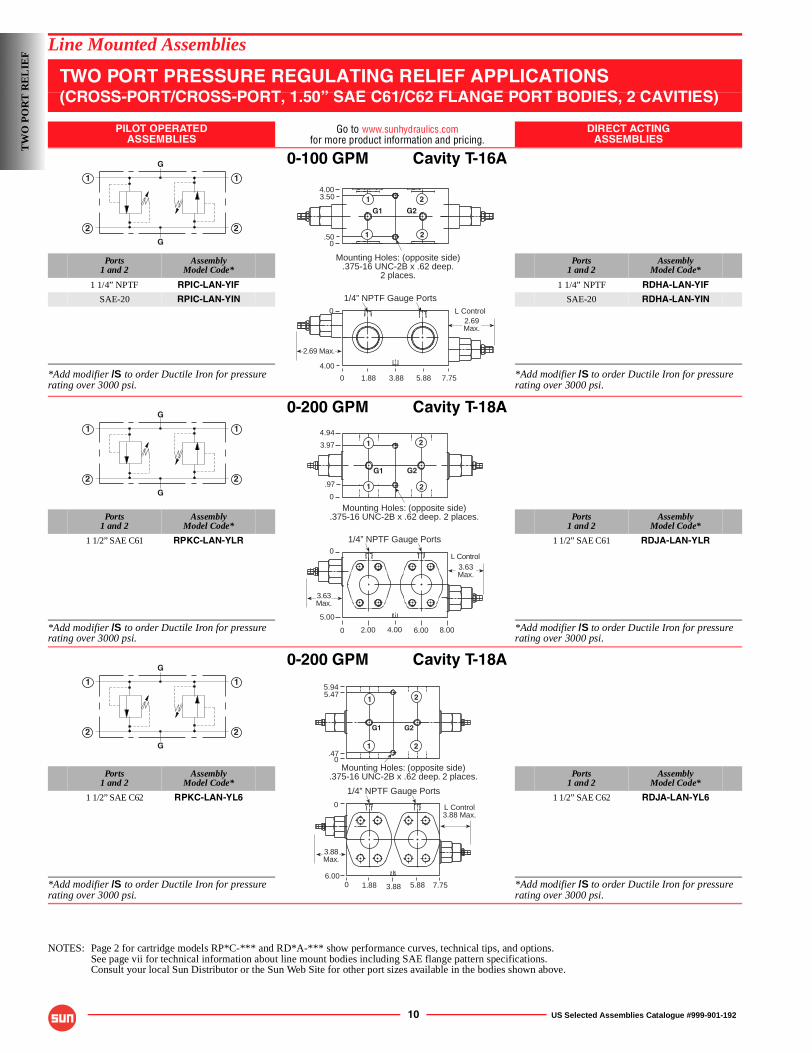
TWO PORT PRESSURE REGULATING RELIEF APPLICATIONS(CROSS-PORT/CROSS-PORT, 1.50” SAE C61/C62 FLANGE PORT BODIES, 2 CAVITIES)
PILOT OPERATEDASSEMBLIES
Go to www.sunhydraulics.comfor more product information and pricing.
DIRECT ACTINGASSEMBLIES
0-100 GPM Cavity T-16A
Ports1 and 2
AssemblyModel Code*
Ports1 and 2
AssemblyModel Code*
1 1/4” NPTF RPIC-LAN-YIF 1 1/4” NPTF RDHA-LAN-YIF
SAE-20 RPIC-LAN-YIN SAE-20 RDHA-LAN-YIN
*Add modifier /S to order Ductile Iron for pressure rating over 3000 psi.
*Add modifier /S to order Ductile Iron for pressure rating over 3000 psi.
0-200 GPM Cavity T-18A
Ports1 and 2
AssemblyModel Code*
Ports1 and 2
AssemblyModel Code*
1 1/2” SAE C61 RPKC-LAN-YLR 1 1/2” SAE C61 RDJA-LAN-YLR
*Add modifier /S to order Ductile Iron for pressure rating over 3000 psi.
*Add modifier /S to order Ductile Iron for pressure rating over 3000 psi.
0-200 GPM Cavity T-18A
Ports1 and 2
AssemblyModel Code*
Ports1 and 2
AssemblyModel Code*
1 1/2” SAE C62 RPKC-LAN-YL6 1 1/2” SAE C62 RDJA-LAN-YL6
*Add modifier /S to order Ductile Iron for pressure rating over 3000 psi.
*Add modifier /S to order Ductile Iron for pressure rating over 3000 psi.
NOTES: Page 2 for cartridge models RP*C-*** and RD*A-*** show performance curves, technical tips, and options.See page vii for technical information about line mount bodies including SAE flange pattern specifications.Consult your local Sun Distributor or the Sun Web Site for other port sizes available in the bodies shown above.
2
1
2
1
G
G
Mounting Holes: (opposite side).375-16 UNC-2B x .62 deep.
2 places.
0
4.003.50
.50
0 7.75
0
4.00
1.88 5.883.88
2.69Max.
1/4” NPTF Gauge PortsL Control
G1 G2
1
1 2
2
2.69 Max.
2
1
2
1
G
G
0
0 8.00
5.00
6.004.002.00
3.63Max.
L Control
Mounting Holes: (opposite side).375-16 UNC-2B x .62 deep. 2 places.
G1 G2
1/4” NPTF Gauge Ports
0
4.941
1 2
23.97
.97
3.63Max.
2
1
2
1
G
G
Mounting Holes: (opposite side).375-16 UNC-2B x .62 deep. 2 places.
0
0
0 7.756.00
3.881.88 5.88
L Control3.88 Max.
5.945.47
.47
G1 G2
1 2
1 2
1/4” NPTF Gauge Ports
3.88Max.
TW
O P
OR
T R
EL
IEF
US Selected Assemblies Catalogue #999-901-192 11
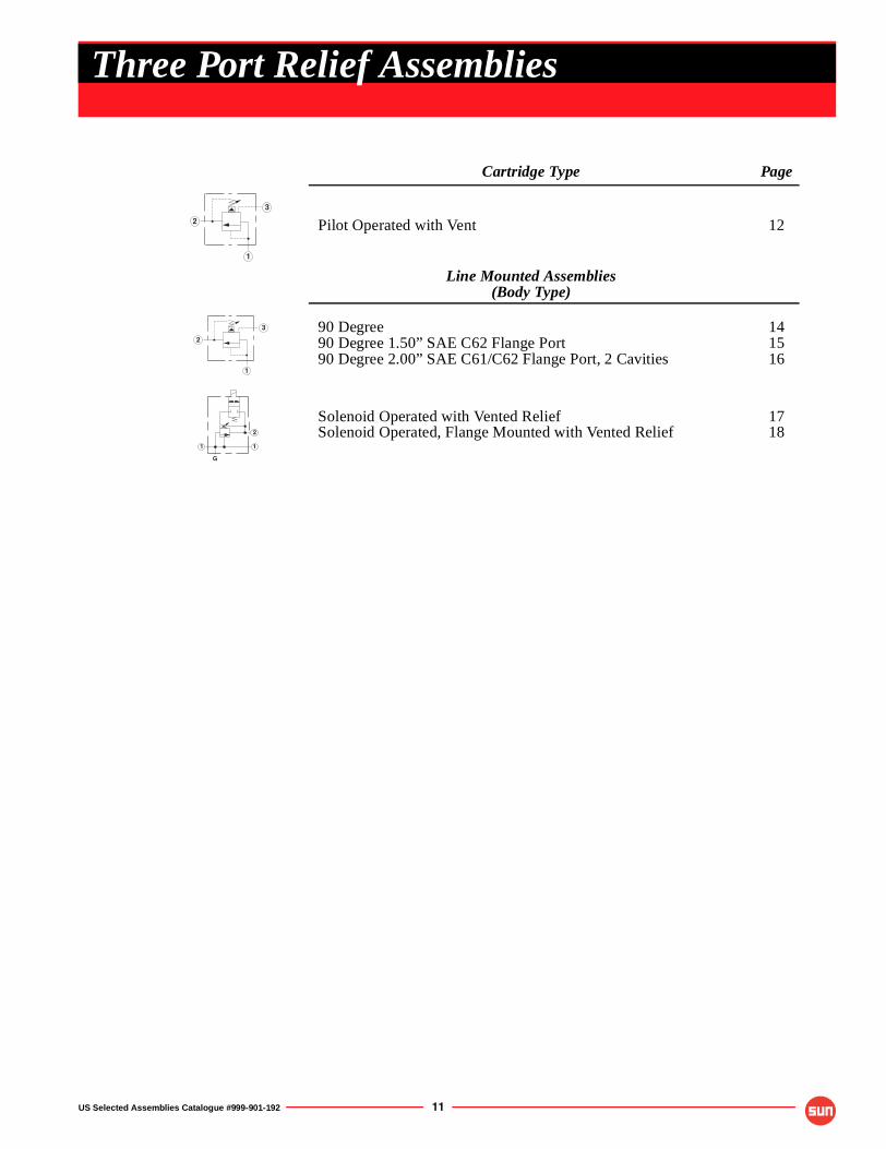
Cartridge Type Page
Pilot Operated with Vent 12
Line Mounted Assemblies(Body Type)
90 Degree90 Degree 1.50” SAE C62 Flange Port90 Degree 2.00” SAE C61/C62 Flange Port, 2 Cavities
141516
Solenoid Operated with Vented ReliefSolenoid Operated, Flange Mounted with Vented Relief
1718
2
3
1
2
3
1
1 1
2
G
Three Port Relief Assemblies
OPTION ORDERING INFORMATION
12 US Selected Assemblies Catalogue #999-901-192
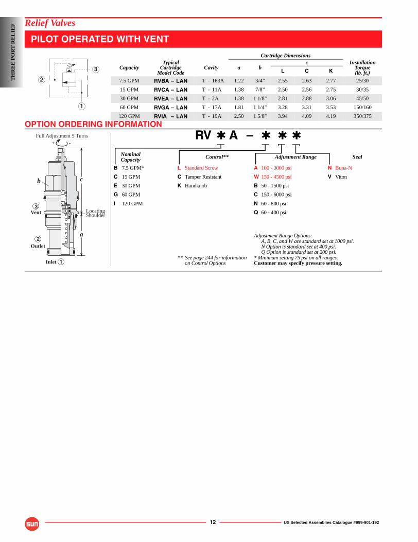
Relief Valves
PILOT OPERATED WITH VENT
RV ✱ A – ✱ ✱ ✱
Nominal Control** Adjustment Range SealCapacity
B 7.5 GPM* L Standard Screw A 100 - 3000 psi N Buna-N
C 15 GPM C Tamper Resistant W 150 - 4500 psi V Viton
E 30 GPM K Handknob B 50 - 1500 psi
G 60 GPM C 150 - 6000 psi
I 120 GPM N 60 - 800 psi
Q 60 - 400 psi
Adjustment Range Options:A, B, C, and W are standard set at 1000 psi.N Option is standard set at 400 psi.Q Option is standard set at 200 psi.
** See page 244 for information * Minimum setting 75 psi on all ranges.on Control Options Customer may specify pressure setting.
Cartridge Dimensions
CapacityTypical
CartridgeModel Code
Cavity a bc Installation
Torque(lb. ft.)L C K
7.5 GPM RVBA – LAN T - 163A 1.22 3/4” 2.55 2.63 2.77 25/30
15 GPM RVCA – LAN T - 11A 1.38 7/8” 2.50 2.56 2.75 30/35
30 GPM RVEA – LAN T - 2A 1.38 1 1/8” 2.81 2.88 3.06 45/50
60 GPM RVGA – LAN T - 17A 1.81 1 1/4” 3.28 3.31 3.53 150/160
120 GPM RVIA – LAN T - 19A 2.50 1 5/8” 3.94 4.09 4.19 350/375
2
3
1
Inlet
Vent3
2
1
-+
LocatingShoulder
Full Adjustment 5 Turns
Outlet
c
a
b
TH
RE
E P
OR
T R
EL
IEF
TECHNICAL TIPS / PERFORMANCE CURVES
US Selected Assemblies Catalogue #999-901-192 13
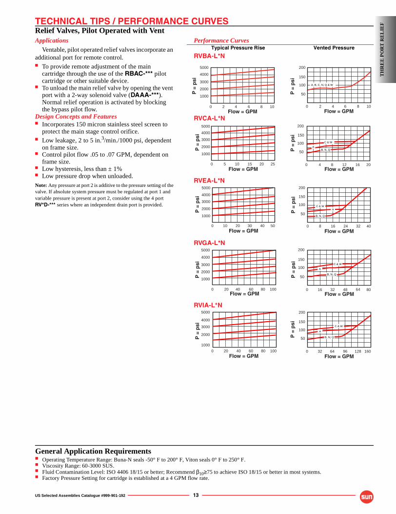
Relief Valves, Pilot Operated with VentApplications
Ventable, pilot operated relief valves incorporate an additional port for remote control.■ To provide remote adjustment of the main
cartridge through the use of the RBAC-*** pilot cartridge or other suitable device.
■ To unload the main relief valve by opening the vent port with a 2-way solenoid valve (DAAA-***). Normal relief operation is activated by blocking the bypass pilot flow.
Design Concepts and Features■ Incorporates 150 micron stainless steel screen to
protect the main stage control orifice.■ Low leakage, 2 to 5 in.3/min./1000 psi, dependent
on frame size.■ Control pilot flow .05 to .07 GPM, dependent on
frame size.■ Low hysteresis, less than ± 1%■ Low pressure drop when unloaded.Note: Any pressure at port 2 is additive to the pressure setting of the valve. If absolute system pressure must be regulated at port 1 and variable pressure is present at port 2, consider using the 4 port RV*D-*** series where an independent drain port is provided.
Performance CurvesTypical Pressure Rise Vented Pressure
RVBA-L*N
RVCA-L*N
RVEA-L*N
RVGA-L*N
RVIA-L*N
Flow = GPM
200
50
100
150
P =
psi
0 2 4 6 8 10
A, B, C, N, Q & W
200
150
100
0 2016 4 8 12
50
Flow = GPM
P =
psi
B, N, QA
C & W
200
150
100
0 4032 8 16 24
50
Flow = GPM
P =
psi
B, N, Q
AC & W
200
150
100
0 8016 32 48
50
Flow = GPMP
= p
si64
B, N, Q
A
C & W
200
150
100
0 160 64 96 128
50
Flow = GPM
P =
psi
32
B, N, Q
A
C & W
0 10080 20 40 60Flow = GPM
P =
psi
5000
4000
3000
2000
1000
0 5040 10 20 30Flow = GPM
P =
psi
5000
4000
3000
2000
1000
0 10080 20 40 60Flow = GPM
P =
psi
5000
4000
3000
2000
1000
Flow = GPM
P =
psi
0
2000
3000
4000
5000
2 4 6 8
1000
10
0 2520 5 10 15Flow = GPM
P =
psi
5000
4000
3000
2000
1000
TH
RE
E P
OR
T R
EL
IEF
General Application Requirements■ Operating Temperature Range: Buna-N seals -50° F to 200° F, Viton seals 0° F to 250° F.■ Viscosity Range: 60-3000 SUS.■ Fluid Contamination Level: ISO 4406 18/15 or better; Recommend β10≥75 to achieve ISO 18/15 or better in most systems.■ Factory Pressure Setting for cartridge is established at a 4 GPM flow rate.
14 US Selected Assemblies Catalogue #999-901-192
Line Mounted Assemblies
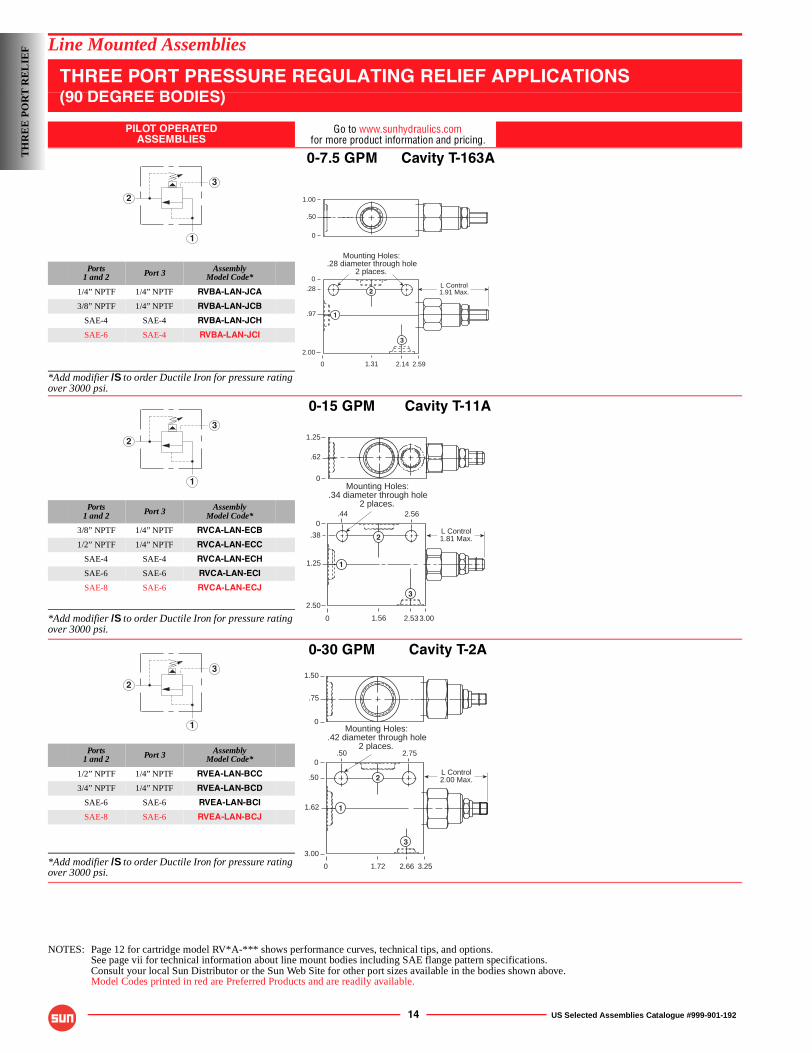
THREE PORT PRESSURE REGULATING RELIEF APPLICATIONS(90 DEGREE BODIES)
PILOT OPERATEDASSEMBLIES
Go to www.sunhydraulics.comfor more product information and pricing.
0-7.5 GPM Cavity T-163A
Ports1 and 2 Port 3 Assembly
Model Code*
1/4” NPTF 1/4” NPTF RVBA-LAN-JCA
3/8” NPTF 1/4” NPTF RVBA-LAN-JCB
SAE-4 SAE-4 RVBA-LAN-JCH
SAE-6 SAE-4 RVBA-LAN-JCI
*Add modifier /S to order Ductile Iron for pressure rating over 3000 psi.
0-15 GPM Cavity T-11A
Ports1 and 2 Port 3 Assembly
Model Code*
3/8” NPTF 1/4” NPTF RVCA-LAN-ECB
1/2” NPTF 1/4” NPTF RVCA-LAN-ECC
SAE-4 SAE-4 RVCA-LAN-ECH
SAE-6 SAE-6 RVCA-LAN-ECI
SAE-8 SAE-6 RVCA-LAN-ECJ
*Add modifier /S to order Ductile Iron for pressure rating over 3000 psi.
0-30 GPM Cavity T-2A
Ports1 and 2 Port 3 Assembly
Model Code*
1/2” NPTF 1/4” NPTF RVEA-LAN-BCC
3/4” NPTF 1/4” NPTF RVEA-LAN-BCD
SAE-6 SAE-6 RVEA-LAN-BCI
SAE-8 SAE-6 RVEA-LAN-BCJ
*Add modifier /S to order Ductile Iron for pressure rating over 3000 psi.
NOTES: Page 12 for cartridge model RV*A-*** shows performance curves, technical tips, and options.See page vii for technical information about line mount bodies including SAE flange pattern specifications.Consult your local Sun Distributor or the Sun Web Site for other port sizes available in the bodies shown above.Model Codes printed in red are Preferred Products and are readily available.
2
3
1
L Control1.91 Max.
Mounting Holes:.28 diameter through hole
2 places.
0
0.28
.97
2.00
2.592.141.31
1.00
.50
0
1
3
2
2
3
1
L Control1.81 Max.
1.25
.62
0
0
0
.38
1.25
2.50
3.002.531.56
Mounting Holes:.34 diameter through hole
2 places.
1
2
3
2.56.44
2
3
1
L Control2.00 Max.
Mounting Holes:.42 diameter through hole
2 places.
0
0
.50
1.62
3.00
3.252.661.72
1.50
.75
0
1
2
3
.50 2.75
TH
RE
E P
OR
T R
EL
IEF
US Selected Assemblies Catalogue #999-901-192 15
Line Mounted Assemblies
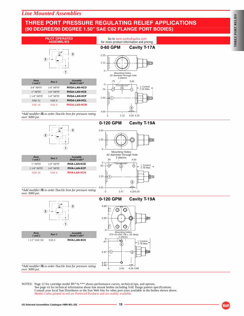
THREE PORT PRESSURE REGULATING RELIEF APPLICATIONS(90 DEGREE/90 DEGREE 1.50” SAE C62 FLANGE PORT BODIES)
PILOT OPERATEDASSEMBLIES
Go to www.sunhydraulics.comfor more product information and pricing.
0-60 GPM Cavity T-17A
Ports1 and 2 Port 3 Assembly
Model Code*
3/4” NPTF 1/4” NPTF RVGA-LAN-HCD
1” NPTF 1/4” NPTF RVGA-LAN-HCE
1 1/4” NPTF 1/4” NPTF RVGA-LAN-HCF
SAE-12 SAE-6 RVGA-LAN-HCL
SAE-16 SAE-6 RVGA-LAN-HCM
*Add modifier /S to order Ductile Iron for pressure rating over 3000 psi.
0-120 GPM Cavity T-19A
Ports1 and 2 Port 3 Assembly
Model Code*
1” NPTF 1/4” NPTF RVIA-LAN-KCE
1 1/4” NPTF 1/4” NPTF RVIA-LAN-KCF
SAE-20 SAE-6 RVIA-LAN-KCN
*Add modifier /S to order Ductile Iron for pressure rating over 3000 psi.
0-120 GPM Cavity T-19A
Ports1 and 2 Port 3 Assembly
Model Code*
1 1/2” SAE C62 SAE-6 RVIA-LAN-KC6
*Add modifier /S to order Ductile Iron for pressure rating over 3000 psi.
NOTES: Page 12 for cartridge model RV*A-*** shows performance curves, technical tips, and options.See page vii for technical information about line mount bodies including SAE flange pattern specifications.Consult your local Sun Distributor or the Sun Web Site for other port sizes available in the bodies shown above.Model Codes printed in red are Preferred Products and are readily available.
2
3
1
0
0
.75
2.00
4.00
4.253.502.12
L Control2.16 Max.
Mounting Holes:.42 diameter through hole
2 places.
1
2
3
2.25
2.12
0
.75 3.50
2
3
1
0
0.50
2.25
4.00
5.004.252.47
L Control2.78 Max.
Mounting Holes:.42 diameter through hole
2 places.
1
2
3
3.00
1.50
0
.50 4.50
2
3
1
4.50
2.25
0
0
Mounting Holes:.375-16 UNC-2B x .62 deep.
2 places.
.47
2.47
4.474.94
0 2.41 4.19 4.94
1
2
3
L Control2.78 Max
TH
RE
E P
OR
T R
EL
IEF
16 US Selected Assemblies Catalogue #999-901-192
Line Mounted Assemblies
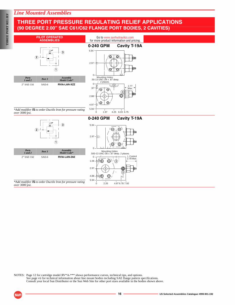
THREE PORT PRESSURE REGULATING RELIEF APPLICATIONS(90 DEGREE 2.00” SAE C61/C62 FLANGE PORT BODIES, 2 CAVITIES)
PILOT OPERATEDASSEMBLIES
Go to www.sunhydraulics.comfor more product information and pricing.
0-240 GPM Cavity T-19A
Ports1 and 2 Port 3 Assembly
Model Code*
2” SAE C61 SAE-6 RVIA-LAN-XZZ
*Add modifier /S to order Ductile Iron for pressure rating over 3000 psi.
0-240 GPM Cavity T-19A
Ports1 and 2 Port 3 Assembly
Model Code*
2” SAE C62 SAE-6 RVIA-LAN-Z8Z
*Add modifier /S to order Ductile Iron for pressure rating over 3000 psi.
NOTES: Page 12 for cartridge model RV*A-*** shows performance curves, technical tips, and options.See page vii for technical information about line mount bodies including SAE flange pattern specifications.Consult your local Sun Distributor or the Sun Web Site for other port sizes available in the bodies shown above.
2
3
1
5.94
2.97
0
1
2
3
Mounting Holes:.50-13 UNC-2B x .87 deep.
2 places.
0 1.97 4.25 6.03 6.755.94
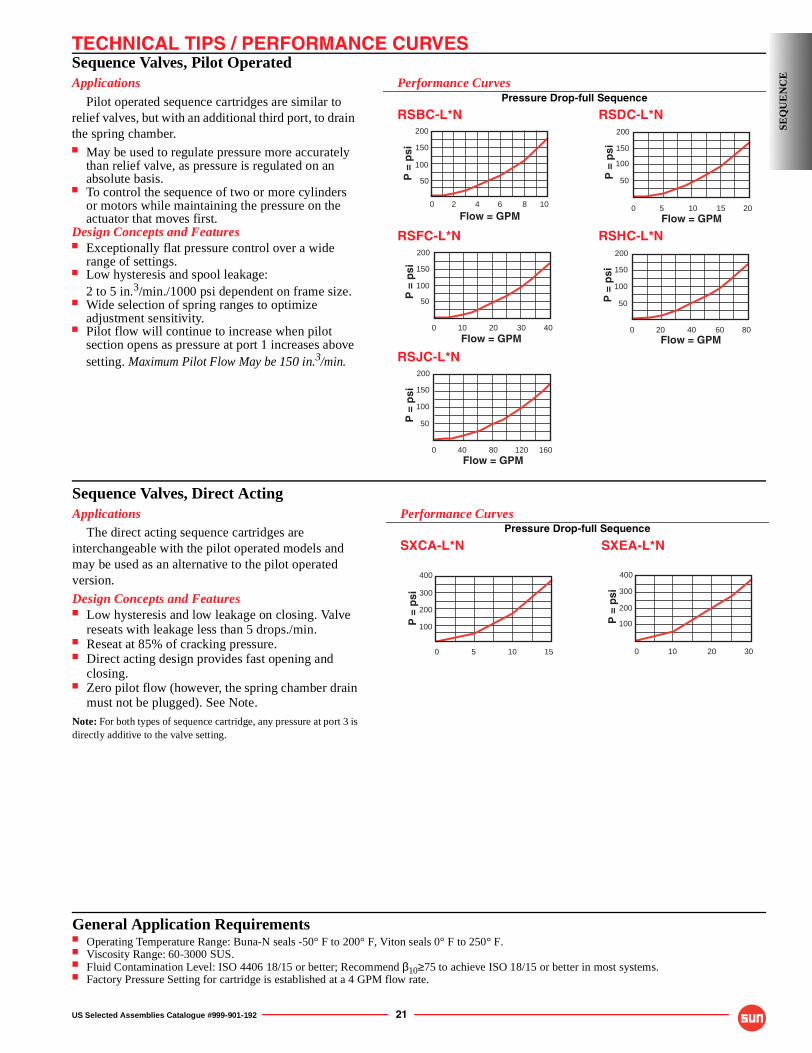
4.97
2.88
.97
02.77Max.
2
3
1
L Control2.78 Max.
5.94
2.97
0Mounting Holes:
.500-13 UNC-2B x .87 deep. 2 places.
0
0
1.06
2.97
5.94
4.972.26
4.88
7.50
1
3
6.78
2
TH
RE
E P
OR
T R
EL
IEF
US Selected Assemblies Catalogue #999-901-192 17
Line Mounted Assemblies
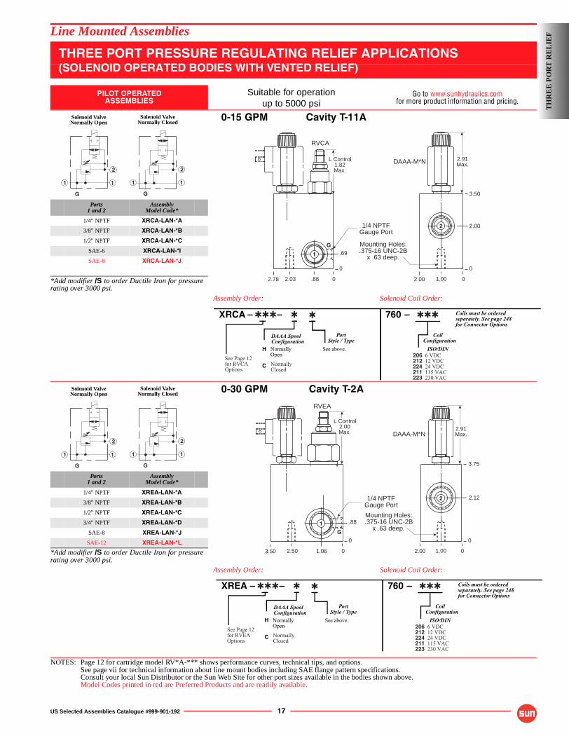
THREE PORT PRESSURE REGULATING RELIEF APPLICATIONS(SOLENOID OPERATED BODIES WITH VENTED RELIEF)
PILOT OPERATEDASSEMBLIES
Suitable for operationup to 5000 psi
Go to www.sunhydraulics.comfor more product information and pricing.
0-15 GPM Cavity T-11A
Ports1 and 2
AssemblyModel Code*
1/4” NPTF XRCA-LAN-*A
3/8” NPTF XRCA-LAN-*B
1/2” NPTF XRCA-LAN-*C
SAE-6 XRCA-LAN-*I
SAE-8 XRCA-LAN-*J
*Add modifier /S to order Ductile Iron for pressure rating over 3000 psi.
Assembly Order: Solenoid Coil Order:
0-30 GPM Cavity T-2A
Ports1 and 2
AssemblyModel Code*
1/4” NPTF XREA-LAN-*A
3/8” NPTF XREA-LAN-*B
1/2” NPTF XREA-LAN-*C
3/4” NPTF XREA-LAN-*D
SAE-8 XREA-LAN-*J
SAE-12 XREA-LAN-*L
*Add modifier /S to order Ductile Iron for pressure rating over 3000 psi.
Assembly Order: Solenoid Coil Order:
NOTES: Page 12 for cartridge model RV*A-*** shows performance curves, technical tips, and options.See page vii for technical information about line mount bodies including SAE flange pattern specifications.Consult your local Sun Distributor or the Sun Web Site for other port sizes available in the bodies shown above.Model Codes printed in red are Preferred Products and are readily available.
Solenoid ValveNormally Open
Solenoid ValveNormally Closed
1
G
1
2
1 1
2
G
2.91Max.
L Control1.82Max.
3.50
2.00
0
.69
0
DAAA-M*N
RVCA
Mounting Holes:.375-16 UNC-2B
x .63 deep.
2.00 01.002.78 02.03 .88
1/4 NPTFGauge Port
2
G
1
XRCA – – 760 – Coils must be orderedseparately. See page 248for Connector Options
DAAA Spool PortConfiguration Style / Type
H Normally See above.Open
C
CoilConfiguration
ISO/DIN
See Page 12for RVCAOptions
NormallyClosed
✱ ✱
6 VDC12 VDC24 VDC115 VAC230 VAC
206212224211223
✱ ✱✱ ✱ ✱✱
Solenoid ValveNormally Open
Solenoid ValveNormally Closed
1
G
1
2
1 1
2
G
L Control2.00Max.
3.75
2.12
0
.88
0
2.91Max.DAAA-M*N
RVEA
Mounting Holes:.375-16 UNC-2B
x .63 deep.
2.00 01.003.50 02.50 1.06
1/4 NPTFGauge Port
1
G
2
XREA – – 760 – Coils must be orderedseparately. See page 248for Connector Options
DAAA Spool PortConfiguration Style / Type
H Normally See above.Open
C
CoilConfiguration
ISO/DIN
See Page 12for RVEAOptions
NormallyClosed
✱ ✱
6 VDC12 VDC24 VDC115 VAC230 VAC
206212224211223
✱ ✱✱ ✱ ✱✱
TH
RE
E P
OR
T R
EL
IEF
18 US Selected Assemblies Catalogue #999-901-192
Line Mounted Assemblies
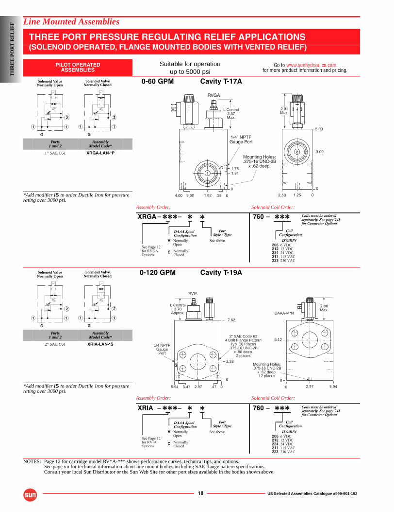
THREE PORT PRESSURE REGULATING RELIEF APPLICATIONS(SOLENOID OPERATED, FLANGE MOUNTED BODIES WITH VENTED RELIEF)
PILOT OPERATEDASSEMBLIES
Suitable for operationup to 5000 psi
Go to www.sunhydraulics.comfor more product information and pricing.
0-60 GPM Cavity T-17A
Ports1 and 2
AssemblyModel Code*
1” SAE C61 XRGA-LAN-*P
*Add modifier /S to order Ductile Iron for pressure rating over 3000 psi.
Assembly Order: Solenoid Coil Order:
0-120 GPM Cavity T-19A
Ports1 and 2
AssemblyModel Code*
2” SAE C61 XRIA-LAN-*S
*Add modifier /S to order Ductile Iron for pressure rating over 3000 psi.
Assembly Order: Solenoid Coil Order:
NOTES: Page 12 for cartridge model RV*A-*** shows performance curves, technical tips, and options.See page vii for technical information about line mount bodies including SAE flange pattern specifications.Consult your local Sun Distributor or the Sun Web Site for other port sizes available in the bodies shown above.
Solenoid ValveNormally Open
Solenoid ValveNormally Closed
1
G
1
2
1 1
2
G
������������ ��������������
�����������
����������������
����
!"#$
�%&'��()*#�����(���
��
����
&� �������� ��+
��,�����
�� ,
��� ����
�
��
XRGA – – 760 – Coils must be orderedseparately. See page 248for Connector Options
DAAA Spool PortConfiguration Style / Type
H Normally See above.Open
C
CoilConfiguration
ISO/DIN
See Page 12for RVGAOptions
NormallyClosed
✱ ✱
6 VDC12 VDC24 VDC115 VAC230 VAC
206212224211223
✱ ✱✱ ✱ ✱✱
Solenoid ValveNormally Open
Solenoid ValveNormally Closed
1
G
1
2
1 1
2
G
2” SAE Code 624 Bolt Flange Pattern
Typ. (3) Places.375-16 UNC-2B
x .88 deep.2 places
L Control2.78
Approx.
RVIA
7.62
2.38
0
02.97 .475.94 5.47
1/4 NPTFGauge
Port
G
2.88Max.
DAAA-M*N
Mounting Holes:.375-16 UNC-2B
x .62 deep.12 places
5.94
0
0 2.97
5.12
XRIA – – 760 – Coils must be orderedseparately. See page 248for Connector Options
DAAA Spool PortConfiguration Style / Type
H Normally See above.Open
C
CoilConfiguration
ISO/DIN
See Page 12for RVIAOptions
NormallyClosed
✱ ✱
6 VDC12 VDC24 VDC115 VAC230 VAC
206212224211223
✱ ✱✱ ✱ ✱✱
TH
RE
E P
OR
T R
EL
IEF
US Selected Assemblies Catalogue #999-901-192 19
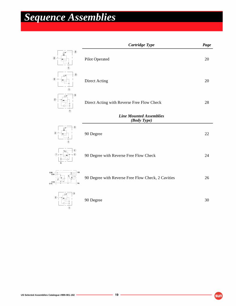
Cartridge Type Page
Pilot Operated 20
Direct Acting 20
Direct Acting with Reverse Free Flow Check 28
Line Mounted Assemblies(Body Type)
90 Degree 22
90 Degree with Reverse Free Flow Check 24
90 Degree with Reverse Free Flow Check, 2 Cavities 26
90 Degree 30
2
1
3
2
3
1
2
1
3
2
1
3
1 2
3
G
C2B
C1A
C2A
C1B
VB
VA
2
1
3
Sequence Assemblies
OPTION ORDERING INFORMATION
OPTION ORDERING INFORMATION
20 US Selected Assemblies Catalogue #999-901-192
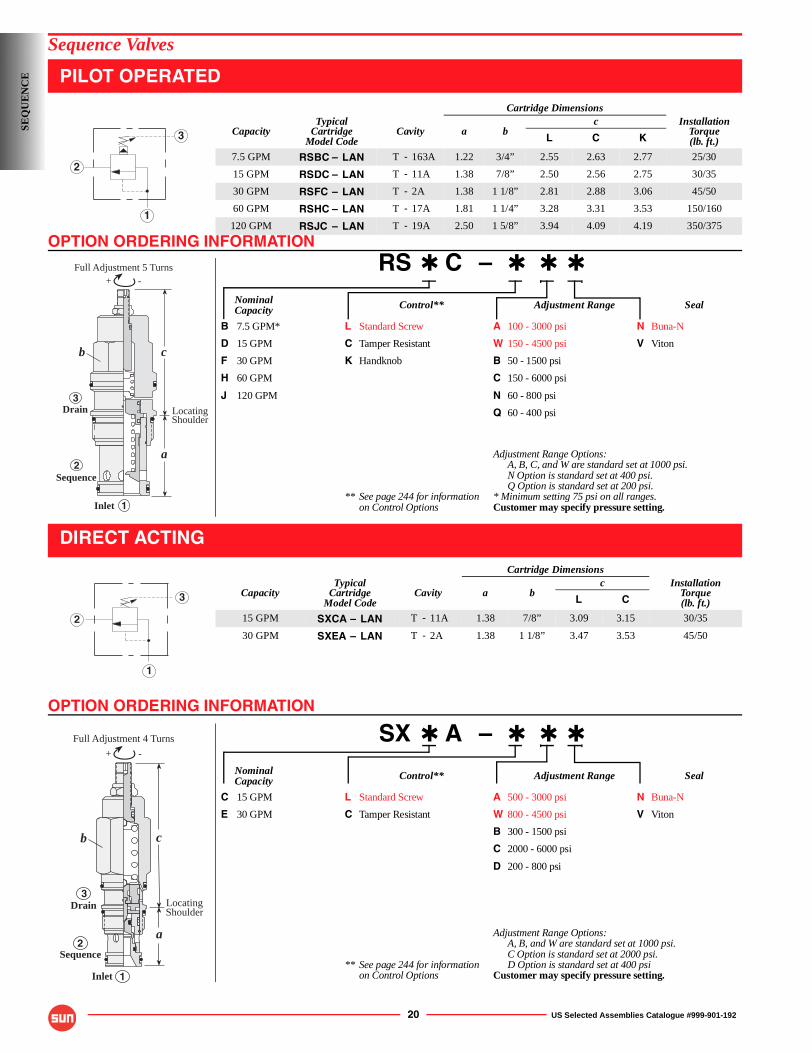
Sequence Valves
PILOT OPERATED
RS ✱ C – ✱ ✱ ✱
Nominal Control** Adjustment Range SealCapacity
B 7.5 GPM* L Standard Screw A 100 - 3000 psi N Buna-N
D 15 GPM C Tamper Resistant W 150 - 4500 psi V Viton
F 30 GPM K Handknob B 50 - 1500 psi
H 60 GPM C 150 - 6000 psi
J 120 GPM N 60 - 800 psi
Q 60 - 400 psi
Adjustment Range Options:A, B, C, and W are standard set at 1000 psi.N Option is standard set at 400 psi.Q Option is standard set at 200 psi.
** See page 244 for information * Minimum setting 75 psi on all ranges.on Control Options Customer may specify pressure setting.
DIRECT ACTING
SX ✱ A – ✱ ✱ ✱
Nominal Control** Adjustment Range SealCapacity
C 15 GPM L Standard Screw A 500 - 3000 psi N Buna-N
E 30 GPM C Tamper Resistant W 800 - 4500 psi V Viton
B 300 - 1500 psi
C 2000 - 6000 psi
D 200 - 800 psi
Adjustment Range Options:A, B, and W are standard set at 1000 psi.C Option is standard set at 2000 psi.
** See page 244 for information D Option is standard set at 400 psion Control Options Customer may specify pressure setting.
Cartridge Dimensions
CapacityTypical
CartridgeModel Code
Cavity a bc Installation
Torque(lb. ft.)L C K
7.5 GPM RSBC – LAN T - 163A 1.22 3/4” 2.55 2.63 2.77 25/30
15 GPM RSDC – LAN T - 11A 1.38 7/8” 2.50 2.56 2.75 30/35
30 GPM RSFC – LAN T - 2A 1.38 1 1/8” 2.81 2.88 3.06 45/50
60 GPM RSHC – LAN T - 17A 1.81 1 1/4” 3.28 3.31 3.53 150/160
120 GPM RSJC – LAN T - 19A 2.50 1 5/8” 3.94 4.09 4.19 350/375
Cartridge Dimensions
CapacityTypical
CartridgeModel Code
Cavity a bc Installation
Torque(lb. ft.)L C
15 GPM SXCA – LAN T - 11A 1.38 7/8” 3.09 3.15 30/35
30 GPM SXEA – LAN T - 2A 1.38 1 1/8” 3.47 3.53 45/50
2
1
3
-+
LocatingShoulder
Full Adjustment 5 Turns
Inlet
Sequence
Drain3
2
1
c
a
b
2
3
1
-+
c
a
Inlet
Drain LocatingShoulder
Sequence
b
Full Adjustment 4 Turns
3
2
1
SEQ
UE
NC
E
TECHNICAL TIPS / PERFORMANCE CURVES
US Selected Assemblies Catalogue #999-901-192 21
Sequence Valves, Pilot OperatedApplications
Pilot operated sequence cartridges are similar to relief valves, but with an additional third port, to drain the spring chamber.■ May be used to regulate pressure more accurately
than relief valve, as pressure is regulated on an absolute basis.
■ To control the sequence of two or more cylinders or motors while maintaining the pressure on the actuator that moves first.
Design Concepts and Features■ Exceptionally flat pressure control over a wide
range of settings.■ Low hysteresis and spool leakage:
2 to 5 in.3/min./1000 psi dependent on frame size.■ Wide selection of spring ranges to optimize
adjustment sensitivity.■ Pilot flow will continue to increase when pilot
section opens as pressure at port 1 increases above setting. Maximum Pilot Flow May be 150 in.3/min.
Performance CurvesPressure Drop-full Sequence
RSBC-L*N RSDC-L*N
RSFC-L*N RSHC-L*N
RSJC-L*N
0
P =
psi
200
100
50
150
40 80 120 160Flow = GPM
0
P =
psi
200
100
50
150
10 20 30 40
Flow = GPM0
P =
psi
200
100
50
150
20 40 60 80Flow = GPM
0Flow = GPM
P =
psi
200
100
50
150
5 10 15 20Flow = GPM
0
100
2 4 6 8
150
10
200
P =
psi
50
SEQ
UE
NC
E
Sequence Valves, Direct ActingApplications
The direct acting sequence cartridges are interchangeable with the pilot operated models and may be used as an alternative to the pilot operated version.
Design Concepts and Features■ Low hysteresis and low leakage on closing. Valve
reseats with leakage less than 5 drops./min.■ Reseat at 85% of cracking pressure.■ Direct acting design provides fast opening and
closing.■ Zero pilot flow (however, the spring chamber drain
must not be plugged). See Note.Note: For both types of sequence cartridge, any pressure at port 3 is directly additive to the valve setting.
Performance CurvesPressure Drop-full Sequence
SXCA-L*N SXEA-L*N
0
P =
psi
400
200
100
300
5 10 15 0
P =
psi
400
200
100
300
10 20 30
General Application Requirements■ Operating Temperature Range: Buna-N seals -50° F to 200° F, Viton seals 0° F to 250° F.■ Viscosity Range: 60-3000 SUS.■ Fluid Contamination Level: ISO 4406 18/15 or better; Recommend β10≥75 to achieve ISO 18/15 or better in most systems.■ Factory Pressure Setting for cartridge is established at a 4 GPM flow rate.
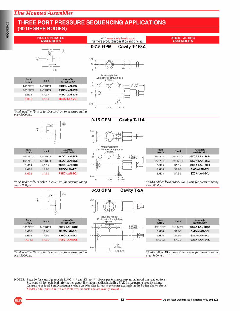
22 US Selected Assemblies Catalogue #999-901-192
Line Mounted Assemblies
THREE PORT PRESSURE SEQUENCING APPLICATIONS(90 DEGREE BODIES)
PILOT OPERATEDASSEMBLIES
Go to www.sunhydraulics.comfor more product information and pricing.
DIRECT ACTINGASSEMBLIES
0-7.5 GPM Cavity T-163A
Ports1 and 2 Port 3 Assembly
Model Code*
1/4” NPTF 1/4” NPTF RSBC-LAN-JCA
3/8” NPTF 1/4” NPTF RSBC-LAN-JCB
SAE-4 SAE-4 RSBC-LAN-JCH
SAE-6 SAE-4 RSBC-LAN-JCI
*Add modifier /S to order Ductile Iron for pressure rating over 3000 psi.
0-15 GPM Cavity T-11A
Ports1 and 2 Port 3 Assembly
Model Code*Ports
1 and 2 Port 3 AssemblyModel Code*
3/8” NPTF 1/4” NPTF RSDC-LAN-ECB 3/8” NPTF 1/4” NPTF SXCA-LAN-ECB
1/2” NPTF 1/4” NPTF RSDC-LAN-ECC 1/2” NPTF 1/4” NPTF SXCA-LAN-ECC
SAE-4 SAE-4 RSDC-LAN-ECH SAE-4 SAE-4 SXCA-LAN-ECH
SAE-6 SAE-6 RSDC-LAN-ECI SAE-6 SAE-6 SXCA-LAN-ECI
SAE-8 SAE-6 RSDC-LAN-ECJ SAE-8 SAE-6 SXCA-LAN-ECJ
*Add modifier /S to order Ductile Iron for pressure rating over 3000 psi.
*Add modifier /S to order Ductile Iron for pressure rating over 3000 psi.
0-30 GPM Cavity T-2A
Ports1 and 2 Port 3 Assembly
Model Code*Ports
1 and 2 Port 3 AssemblyModel Code*
3/4” NPTF 1/4” NPTF RSFC-LAN-BCD 3/4” NPTF 1/4” NPTF SXEA-LAN-BCD
SAE-6 SAE-6 RSFC-LAN-BCI SAE-6 SAE-6 SXEA-LAN-BCI
SAE-8 SAE-6 RSFC-LAN-BCJ SAE-8 SAE-6 SXEA-LAN-BCJ
SAE-12 SAE-6 RSFC-LAN-BCL SAE-12 SAE-6 SXEA-LAN-BCL
*Add modifier /S to order Ductile Iron for pressure rating over 3000 psi.
*Add modifier /S to order Ductile Iron for pressure rating over 3000 psi.
NOTES: Page 20 for cartridge models RS*C-*** and SX*A-*** shows performance curves, technical tips, and options.See page vii for technical information about line mount bodies including SAE flange pattern specifications.Consult your local Sun Distributor or the Sun Web Site for other port sizes available in the bodies shown above.Model Codes printed in red are Preferred Products and are readily available.
2
1
3
L Control1.91 Max.
Mounting Holes:.28 diameter through hole
2 places.
0
0.28
.97
2.00
2.592.141.31
1.00
.50
0
1
2
3
2
3
1
L Control2.40 Max.
1.25
.62
0
0
0
.38
1.25
2.50
3.002.531.56
Mounting Holes:.34 diameter through hole
2 places.
1
2
3
2
3
1
L Control2.66 Max.
Mounting Holes:.42 diameter through hole
2 places.
0
0
.50
1.62
3.00
3.252.661.72
1.50
.75
0
1
2
3
SEQ
UE
NC
E
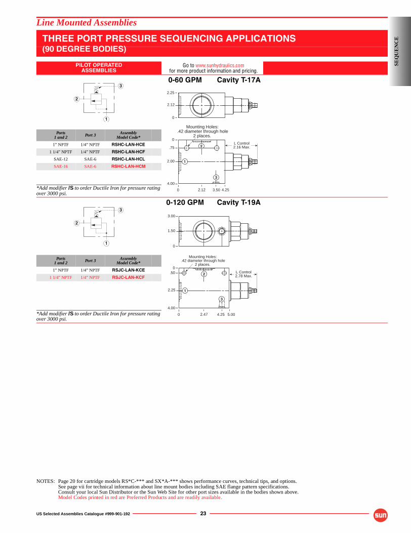
US Selected Assemblies Catalogue #999-901-192 23
Line Mounted Assemblies
THREE PORT PRESSURE SEQUENCING APPLICATIONS(90 DEGREE BODIES)
PILOT OPERATEDASSEMBLIES
Go to www.sunhydraulics.comfor more product information and pricing.
0-60 GPM Cavity T-17A
Ports1 and 2 Port 3 Assembly
Model Code*
1” NPTF 1/4” NPTF RSHC-LAN-HCE
1 1/4” NPTF 1/4” NPTF RSHC-LAN-HCF
SAE-12 SAE-6 RSHC-LAN-HCL
SAE-16 SAE-6 RSHC-LAN-HCM
*Add modifier /S to order Ductile Iron for pressure rating over 3000 psi.
0-120 GPM Cavity T-19A
Ports1 and 2 Port 3 Assembly
Model Code*
1” NPTF 1/4” NPTF RSJC-LAN-KCE
1 1/4” NPTF 1/4” NPTF RSJC-LAN-KCF
*Add modifier /S to order Ductile Iron for pressure rating over 3000 psi.
NOTES: Page 20 for cartridge models RS*C-*** and SX*A-*** shows performance curves, technical tips, and options.See page vii for technical information about line mount bodies including SAE flange pattern specifications.Consult your local Sun Distributor or the Sun Web Site for other port sizes available in the bodies shown above.Model Codes printed in red are Preferred Products and are readily available.
2
1
3
0
0
.75
2.00
4.00
4.253.502.12
L Control2.16 Max.
Mounting Holes:.42 diameter through hole
2 places.
2.25
2.12
0
1
2
3
2
1
3
0
0.50
2.25
4.00
5.004.252.47
L Control2.78 Max.
Mounting Holes:.42 diameter through hole
2 places.
3.00
1.50
0
1
2
3
SEQ
UE
NC
E
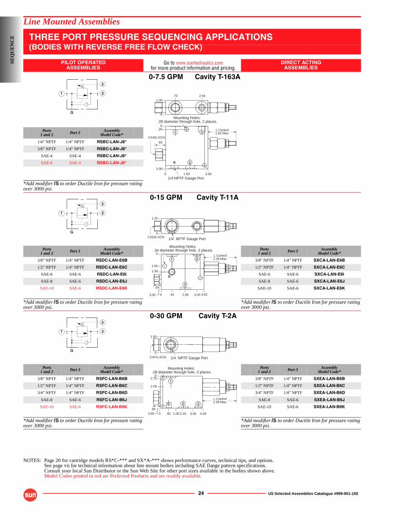
24 US Selected Assemblies Catalogue #999-901-192
Line Mounted Assemblies
THREE PORT PRESSURE SEQUENCING APPLICATIONS(BODIES WITH REVERSE FREE FLOW CHECK)
PILOT OPERATEDASSEMBLIES
Go to www.sunhydraulics.comfor more product information and pricing.
DIRECT ACTINGASSEMBLIES
0-7.5 GPM Cavity T-163A
Ports1 and 2 Port 3 Assembly
Model Code*
1/4” NPTF 1/4” NPTF RSBC-LAN-J6*
3/8” NPTF 1/4” NPTF RSBC-LAN-J6*
SAE-4 SAE-4 RSBC-LAN-J6*
SAE-6 SAE-4 RSBC-LAN-J6*
*Add modifier /S to order Ductile Iron for pressure rating over 3000 psi.
0-15 GPM Cavity T-11A
Ports1 and 2 Port 3 Assembly
Model Code*Ports
1 and 2 Port 3 AssemblyModel Code*
3/8” NPTF 1/4” NPTF RSDC-LAN-E6B 3/8” NPTF 1/4” NPTF SXCA-LAN-E6B
1/2” NPTF 1/4” NPTF RSDC-LAN-E6C 1/2” NPTF 1/4” NPTF SXCA-LAN-E6C
SAE-6 SAE-6 RSDC-LAN-E6I SAE-6 SAE-6 SXCA-LAN-E6I
SAE-8 SAE-6 RSDC-LAN-E6J SAE-8 SAE-6 SXCA-LAN-E6J
SAE-10 SAE-6 RSDC-LAN-E6K SAE-10 SAE-6 SXCA-LAN-E6K
*Add modifier /S to order Ductile Iron for pressure rating over 3000 psi.
*Add modifier /S to order Ductile Iron for pressure rating over 3000 psi.
0-30 GPM Cavity T-2A
Ports1 and 2 Port 3 Assembly
Model Code*Ports
1 and 2 Port 3 AssemblyModel Code*
3/8” NPTF 1/4” NPTF RSFC-LAN-B6B 3/8” NPTF 1/4” NPTF SXEA-LAN-B6B
1/2” NPTF 1/4” NPTF RSFC-LAN-B6C 1/2” NPTF 1/4” NPTF SXEA-LAN-B6C
3/4” NPTF 1/4” NPTF RSFC-LAN-B6D 3/4” NPTF 1/4” NPTF SXEA-LAN-B6D
SAE-8 SAE-6 RSFC-LAN-B6J SAE-8 SAE-6 SXEA-LAN-B6J
SAE-10 SAE-6 RSFC-LAN-B6K SAE-10 SAE-6 SXEA-LAN-B6K
*Add modifier /S to order Ductile Iron for pressure rating over 3000 psi.
*Add modifier /S to order Ductile Iron for pressure rating over 3000 psi.
NOTES: Page 20 for cartridge models RS*C-*** and SX*A-*** shows performance curves, technical tips, and options.See page vii for technical information about line mount bodies including SAE flange pattern specifications.Consult your local Sun Distributor or the Sun Web Site for other port sizes available in the bodies shown above.Model Codes printed in red are Preferred Products and are readily available.
1 2
3
G
.63
Mounting Holes:.28 diameter through hole, 2 places.
1.00
0
L Control1.92 Max.
0
0.25
3.00
3.001.50
.70
CXAD-XCN
G
1
2
3
1/4 NPTF Gauge Port
2.56
1 2
3
G
.59
Mounting Holes:.34 diameter through hole, 2 places.
1/4 NPTF Gauge Port
1.25
0
L Control2.28 Max.
0
0
1.00
1.50
3.00 3.622.06.91 3.03
G
1
2
3
CXDA-XCN
1 2
3
G
Mounting Holes:.28 diameter through hole, 2 places.
1/4 NPTF Gauge Port
G
1.50
0
1
2 3
L Control2.39 Max.
0
02.75
2.00
4.002.19.81 3.561.00
CXFA-XCN
.66
3.00
SEQ
UE
NC
E

US Selected Assemblies Catalogue #999-901-192 25
Line Mounted Assemblies
THREE PORT PRESSURE SEQUENCING APPLICATIONS(BODIES WITH REVERSE FREE FLOW CHECK)
PILOT OPERATEDASSEMBLIES
Go to www.sunhydraulics.comfor more product information and pricing.
0-60 GPM Cavity T-17A
Ports1 and 2 Port 3 Assembly
Model Code*
1” NPTF 1/4” NPTF RSHC-LAN-H6E
1 1/4” NPTF 1/4” NPTF RSHC-LAN-H6F
SAE-12 SAE-6 RSHC-LAN-H6L
SAE-16 SAE-6 RSHC-LAN-H6M
*Add modifier /S to order Ductile Iron for pressure rating over 3000 psi.
0-120 GPM Cavity T-19A
Ports1 and 2 Port 3 Assembly
Model Code*
1” NPTF 1/4” NPTF RSJC-LAN-K6E
1 1/4” NPTF 1/4” NPTF RSJC-LAN-K6F
*Add modifier /S to order Ductile Iron for pressure rating over 3000 psi.
NOTES: Page 20 for cartridge models RS*C-*** and SX*A-*** shows performance curves, technical tips, and options.See page vii for technical information about line mount bodies including SAE flange pattern specifications.Consult your local Sun Distributor or the Sun Web Site for other port sizes available in the bodies shown above.Model Codes printed in red are Preferred Products and are readily available.
1 2
3
G
.59
Mounting Holes:.34 diameter through hole, 2 places.
1/4” NPTF Gauge Port
1.25
0
L Control2.28 Max.
0
0
1.00
1.50
3.00 3.622.06.91 3.03
G
1
2
3
CXDA-XCN
1 2
3
G
Mounting Holes:.42 diameter through hole, 2 places.
1/4 NPTF Gauge Port
G
2.72Max.
0
3.00
0
6.00
4.00
0
7.004.411.88.50 6.22
L Control
1
2
3
CXJA-XCN
1.43
SEQ
UE
NC
E
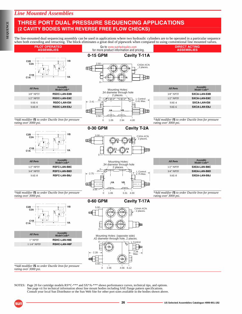
26 US Selected Assemblies Catalogue #999-901-192
Line Mounted Assemblies
THREE PORT DUAL PRESSURE SEQUENCING APPLICATIONS(2 CAVITY BODIES WITH REVERSE FREE FLOW CHECKS)
The line-mounted dual sequencing assembly can be used in applications where two hydraulic cylinders are to be operated in a particular sequence when both extending and retracting. The block eliminates a great deal of pipework when compared to using conventional line mounted valves.
PILOT OPERATEDASSEMBLIES
Go to www.sunhydraulics.comfor more product information and pricing.
DIRECT ACTINGASSEMBLIES
0-15 GPM Cavity T-11A
All Ports AssemblyModel Code* All Ports Assembly
Model Code*
3/8” NPTF RSDC-LAN-E8B 3/8” NPTF SXCA-LAN-E8B
1/2” NPTF RSDC-LAN-E8C 1/2” NPTF SXCA-LAN-E8C
SAE-6 RSDC-LAN-E8I SAE-4 SXCA-LAN-E8I
SAE-8 RSDC-LAN-E8J SAE-6 SXCA-LAN-E8J
*Add modifier /S to order Ductile Iron for pressure rating over 3000 psi.
*Add modifier /S to order Ductile Iron for pressure rating over 3000 psi.
0-30 GPM Cavity T-2A
All Ports AssemblyModel Code* All Ports Assembly
Model Code*
1/2” NPTF RSFC-LAN-B8C 1/2” NPTF SXEA-LAN-B8C
3/4” NPTF RSFC-LAN-B8D 3/4” NPTF SXEA-LAN-B8D
SAE-8 RSFC-LAN-B8J SAE-8 SXEA-LAN-B8J
*Add modifier /S to order Ductile Iron for pressure rating over 3000 psi.
*Add modifier /S to order Ductile Iron for pressure rating over 3000 psi.
0-60 GPM Cavity T-17A
All Ports AssemblyModel Code*
1” NPTF RSHC-LAN-H8E
1 1/4” NPTF RSHC-LAN-H8F
*Add modifier /S to order Ductile Iron for pressure rating over 3000 psi.
NOTES: Page 20 for cartridge models RS*C-*** and SX*A-*** shows performance curves, technical tips, and options.See page vii for technical information about line mount bodies including SAE flange pattern specifications.Consult your local Sun Distributor or the Sun Web Site for other port sizes available in the bodies shown above.
C2B
C1A
C2A
C1B
VB
VA
C2B
2.50
0
C1B
C1A C2A
CXDA-XCN2 places.
Mounting Holes:.34 diameter through hole
2 places.
0
0
2.50
4.002.941.06
.31 L Control2.41 Max.
VA VB
2.41
C2B
C1A
C2A
C1B
VB
VA
Mounting Holes:.34 diameter through hole
2 places.
0
0
3.00
4.003.311.06
.25 L Control2.75 Max.
VA VB
C2
3.00
0
BC1B
C1A
C2A
CXFA-XCN2 places.
2.75
C2B
C1A
C2A
C1B
VB
VA
L Control
5.00
0
Mounting Holes: (opposite side).42 diameter through hole, 2 places.
0
0
5.00
6.124.561.56
CXHA-XCN2 places.C2BC1B
C1A C2A
VA
VB
2.28Max.
2.28
SEQ
UE
NC
E
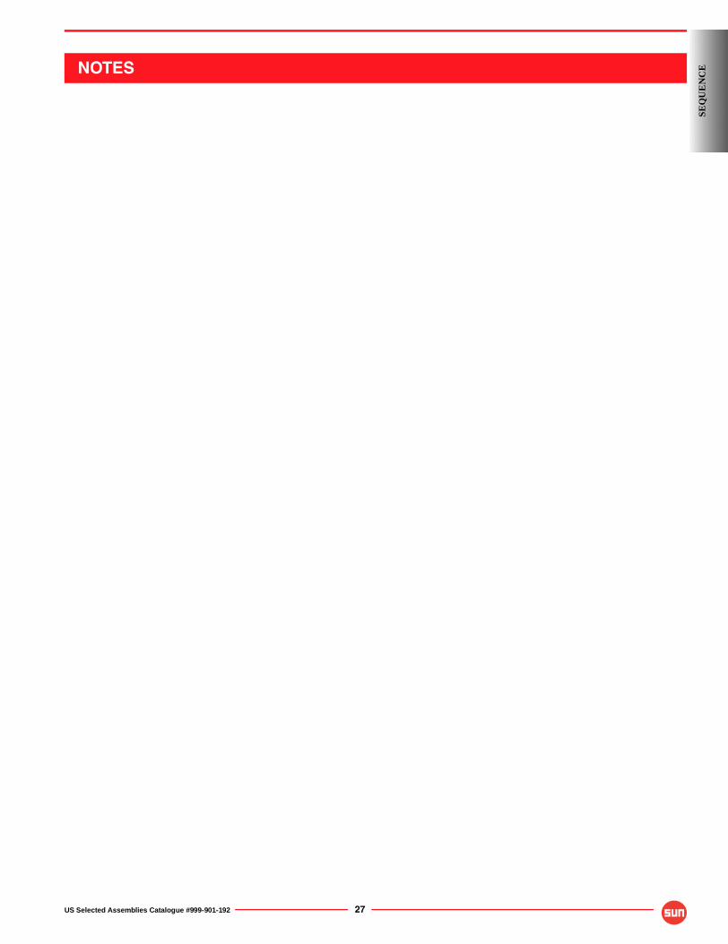
US Selected Assemblies Catalogue #999-901-192 27
SEQ
UE
NC
ENOTES
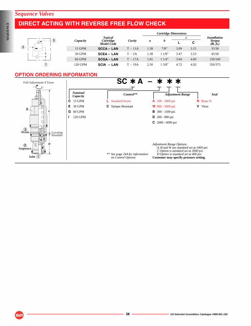
OPTION ORDERING INFORMATION
28 US Selected Assemblies Catalogue #999-901-192
Sequence Valves
DIRECT ACTING WITH REVERSE FREE FLOW CHECK
SC ✱ A – ✱ ✱ ✱
Nominal Control** Adjustment Range SealCapacity
C 15 GPM L Standard Screw A 500 - 3000 psi N Buna-N
E 30 GPM C Tamper Resistant W 800 - 4500 psi V Viton
G 60 GPM B 300 - 1500 psi
I 120 GPM D 200 - 800 psi
C 2000 - 6000 psi
Adjustment Range Options:A, B and W are standard set at 1000 psi.C Option is standard set at 2000 psi.
** See page 244 for information D Option is standard set at 400 psi.on Control Options Customer may specify pressure setting.
Cartridge Dimensions
CapacityTypical
CartridgeModel Code
Cavity a bc Installation
Torque(lb. ft.)L C
15 GPM SCCA – LAN T - 11A 1.38 7/8” 3.09 3.15 35/30
30 GPM SCEA – LAN T - 2A 1.38 1 1/8” 3.47 3.53 45/50
60 GPM SCGA – LAN T - 17A 1.81 1 1/4” 3.94 4.00 150/160
120 GPM SCIA – LAN T - 19A 2.50 1 5/8” 4.72 4.92 350/375
2
1
3
-+
c
a
Inlet
Drain LocatingShoulder
Full Adjustment 4 Turns
Sequence
b
3
2
1
SEQ
UE
NC
E
TECHNICAL TIPS / PERFORMANCE CURVES
US Selected Assemblies Catalogue #999-901-192 29
Sequence Valves, Reverse Free Flow CheckApplications
SC*A series of sequence valves have an integral reverse free flow check and may be used in a similar manner to the cartridges without the check.
Design Concepts and Features■ This is a zero pilot flow valve. Port 3 must not be
plugged.■ Pressure at Port 3 is directly additive to valve
setting.■ Typical response time is 2 ms.■ Maximum leakage is 10 drops/min. at reseat.■ Reseat exceeds 85% of set pressure.■ Reverse free flow check cracking pressure is 20 psi
to 45 psi, depending on frame size.
Flow = GPM0
100
3 6 9 12
200
15
300
P =
psi
Flow = GPM0
100
6 12 18 24
200
30
300
P =
psi
Flow = GPM0
100
12 24 36 48
200
60
300
P =
psi
0
100
24 48 72 120
200
96
300
P =
psi
Flow = GPM
Performance CurvesPressure Drop-full Sequence Reverse Free Flow
SCCA-L*N
SCEA-L*N
SCGA-L*N
SCIA-L*N
Flow = GPM0
100
12 24 36 48
200
60
300
P =
psi
Flow = GPM0
100
24 48 72 120
200
96
300
P =
psi
Flow = GPM0
100
3 6 9 12
200
15
300
P =
psi
Flow = GPM0
100
6 12 18 24
200
30
300
P =
psi
General Application Requirements■ Operating Temperature Range: Buna-N seals -50° F to 200° F, Viton seals 0° F to 250° F.■ Viscosity Range: 60-3000 SUS.■ Fluid Contamination Level: ISO 4406 18/15 or better; Recommend β10≥75 to achieve ISO 18/15 or better in most systems.■ Factory Pressure Setting for cartridge is established at a 4 GPM flow rate.
SEQ
UE
NC
E
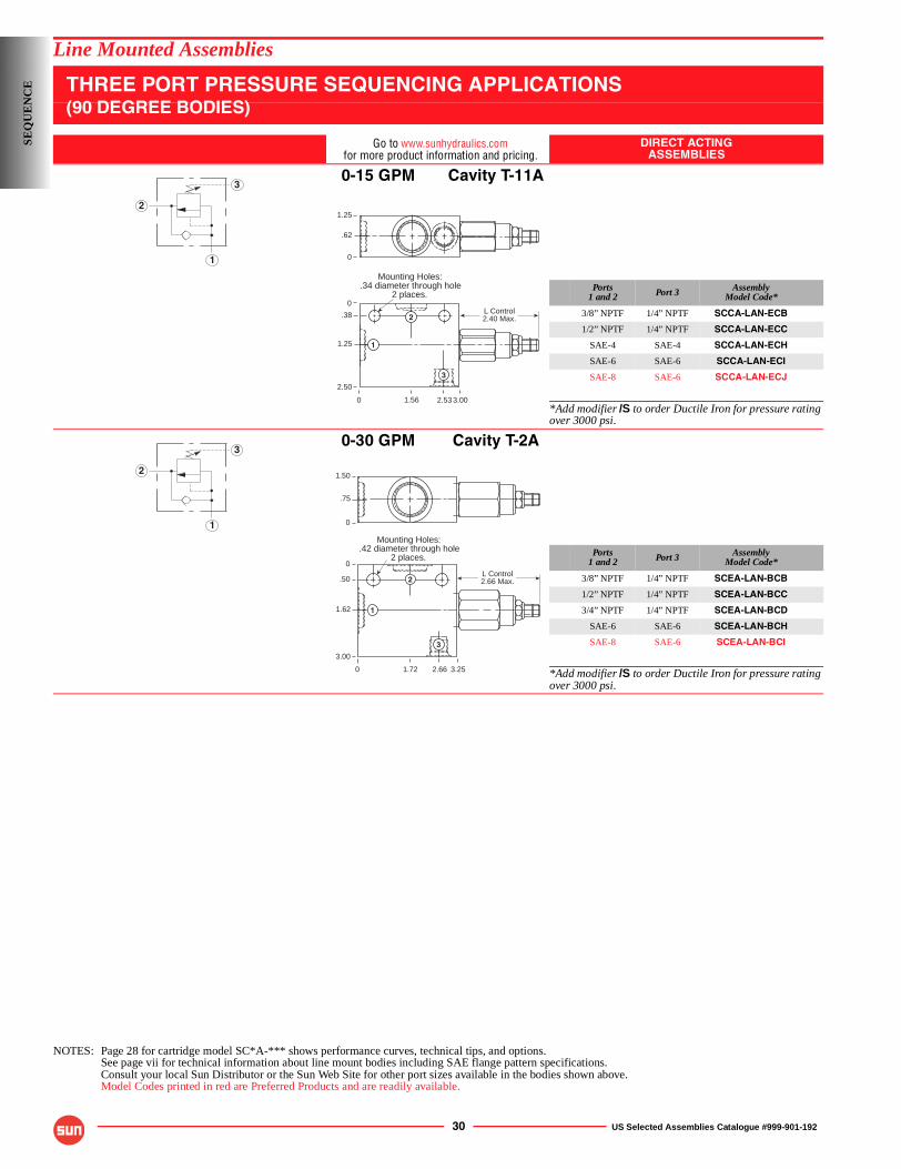
30 US Selected Assemblies Catalogue #999-901-192
Line Mounted Assemblies
THREE PORT PRESSURE SEQUENCING APPLICATIONS(90 DEGREE BODIES)
Go to www.sunhydraulics.comfor more product information and pricing.
DIRECT ACTINGASSEMBLIES
0-15 GPM Cavity T-11A
Ports1 and 2 Port 3 Assembly
Model Code*
3/8” NPTF 1/4” NPTF SCCA-LAN-ECB
1/2” NPTF 1/4” NPTF SCCA-LAN-ECC
SAE-4 SAE-4 SCCA-LAN-ECH
SAE-6 SAE-6 SCCA-LAN-ECI
SAE-8 SAE-6 SCCA-LAN-ECJ
*Add modifier /S to order Ductile Iron for pressure rating over 3000 psi.
0-30 GPM Cavity T-2A
Ports1 and 2 Port 3 Assembly
Model Code*
3/8” NPTF 1/4” NPTF SCEA-LAN-BCB
1/2” NPTF 1/4” NPTF SCEA-LAN-BCC
3/4” NPTF 1/4” NPTF SCEA-LAN-BCD
SAE-6 SAE-6 SCEA-LAN-BCH
SAE-8 SAE-6 SCEA-LAN-BCI
*Add modifier /S to order Ductile Iron for pressure rating over 3000 psi.
NOTES: Page 28 for cartridge model SC*A-*** shows performance curves, technical tips, and options.See page vii for technical information about line mount bodies including SAE flange pattern specifications.Consult your local Sun Distributor or the Sun Web Site for other port sizes available in the bodies shown above.Model Codes printed in red are Preferred Products and are readily available.
2
1
3
L Control2.40 Max.
1.25
.62
0
0
0
.38
1.25
2.50
3.002.531.56
Mounting Holes:.34 diameter through hole
2 places.
1
2
3
2
1
3
L Control2.66 Max.
Mounting Holes:.42 diameter through hole
2 places.
0
0
.50
1.62
3.00
3.252.661.72
1.50
.75
0
1
2
3
SEQ
UE
NC
E
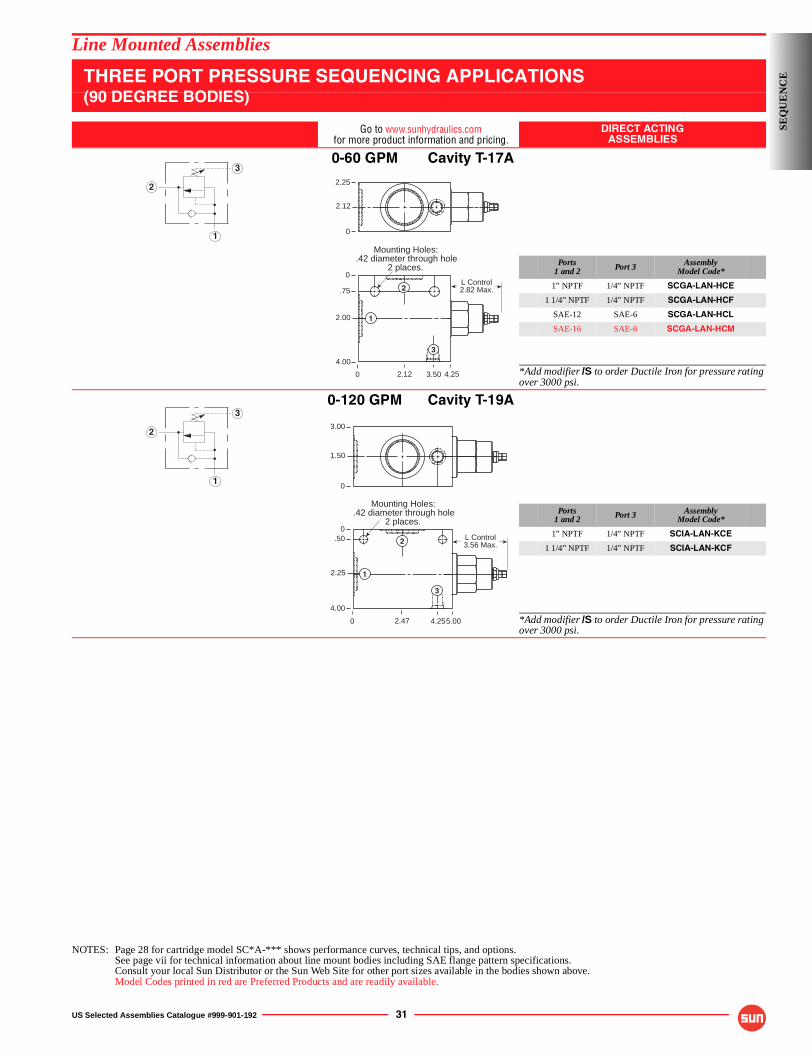
US Selected Assemblies Catalogue #999-901-192 31
Line Mounted Assemblies
THREE PORT PRESSURE SEQUENCING APPLICATIONS(90 DEGREE BODIES)
Go to www.sunhydraulics.comfor more product information and pricing.
DIRECT ACTINGASSEMBLIES
0-60 GPM Cavity T-17A
Ports1 and 2 Port 3 Assembly
Model Code*
1” NPTF 1/4” NPTF SCGA-LAN-HCE
1 1/4” NPTF 1/4” NPTF SCGA-LAN-HCF
SAE-12 SAE-6 SCGA-LAN-HCL
SAE-16 SAE-6 SCGA-LAN-HCM
*Add modifier /S to order Ductile Iron for pressure rating over 3000 psi.
0-120 GPM Cavity T-19A
Ports1 and 2 Port 3 Assembly
Model Code*
1” NPTF 1/4” NPTF SCIA-LAN-KCE
1 1/4” NPTF 1/4” NPTF SCIA-LAN-KCF
*Add modifier /S to order Ductile Iron for pressure rating over 3000 psi.
NOTES: Page 28 for cartridge model SC*A-*** shows performance curves, technical tips, and options.See page vii for technical information about line mount bodies including SAE flange pattern specifications.Consult your local Sun Distributor or the Sun Web Site for other port sizes available in the bodies shown above.Model Codes printed in red are Preferred Products and are readily available.
2
1
3
0
0
.75
2.00
4.00
4.253.502.12
L Control2.82 Max.
Mounting Holes:.42 diameter through hole
2 places.
2.25
2.12
0
1
2
3
2
1
3
0
0.50
2.25
4.00
5.004.252.47
L Control3.56 Max.
Mounting Holes:.42 diameter through hole
2 places.
3.00
1.50
0
1
2
3
SEQ
UE
NC
E
32 US Selected Assemblies Catalogue #999-901-192
SEQ
UE
NC
E NOTES
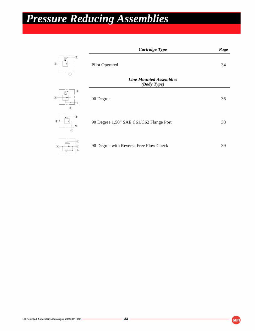
US Selected Assemblies Catalogue #999-901-192 33
Cartridge Type Page
Pilot Operated 34
Line Mounted Assemblies(Body Type)
90 Degree 36
90 Degree 1.50” SAE C61/C62 Flange Port 38
90 Degree with Reverse Free Flow Check 39
2
1
3
G
2
3
1
3
2
1
G
1
3
2
G
Pressure Reducing Assemblies
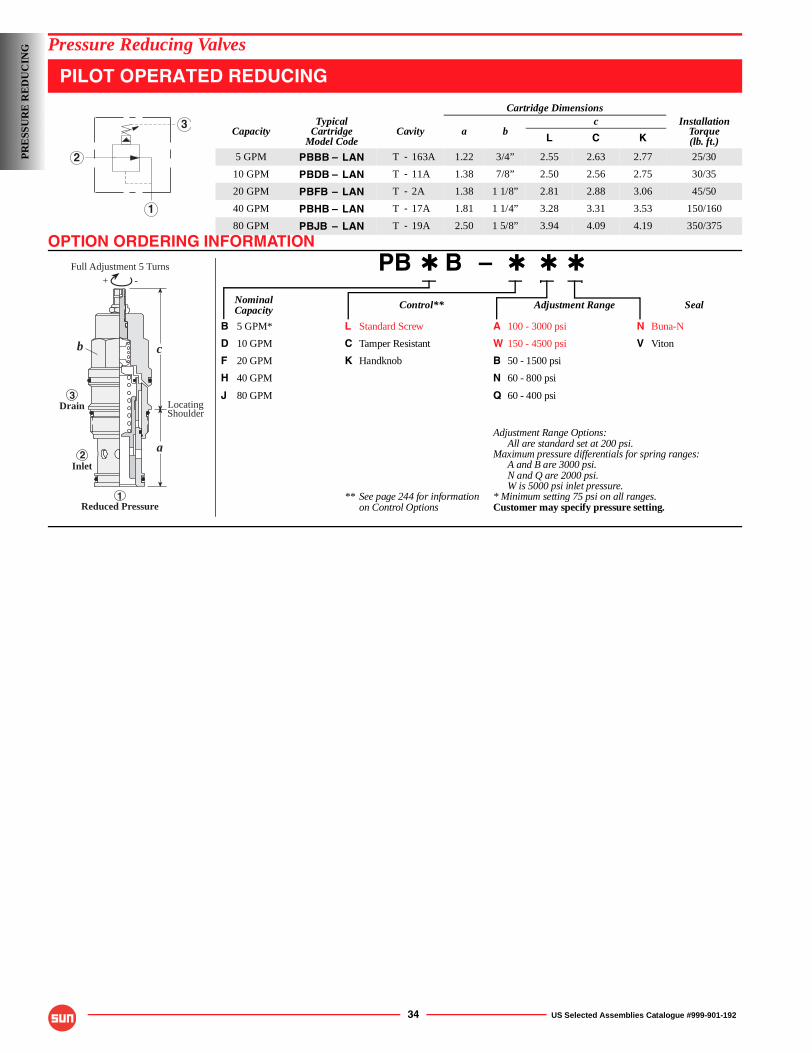
OPTION ORDERING INFORMATION
34 US Selected Assemblies Catalogue #999-901-192
Pressure Reducing Valves
PILOT OPERATED REDUCING
PB ✱ B – ✱ ✱ ✱
Nominal Control** Adjustment Range SealCapacity
B 5 GPM* L Standard Screw A 100 - 3000 psi N Buna-N
D 10 GPM C Tamper Resistant W 150 - 4500 psi V Viton
F 20 GPM K Handknob B 50 - 1500 psi
H 40 GPM N 60 - 800 psi
J 80 GPM Q 60 - 400 psi
Adjustment Range Options:All are standard set at 200 psi.
Maximum pressure differentials for spring ranges:A and B are 3000 psi.N and Q are 2000 psi.W is 5000 psi inlet pressure.
** See page 244 for information * Minimum setting 75 psi on all ranges.on Control Options Customer may specify pressure setting.
Cartridge Dimensions
CapacityTypical
CartridgeModel Code
Cavity a bc Installation
Torque(lb. ft.)L C K
5 GPM PBBB – LAN T - 163A 1.22 3/4” 2.55 2.63 2.77 25/30
10 GPM PBDB – LAN T - 11A 1.38 7/8” 2.50 2.56 2.75 30/35
20 GPM PBFB – LAN T - 2A 1.38 1 1/8” 2.81 2.88 3.06 45/50
40 GPM PBHB – LAN T - 17A 1.81 1 1/4” 3.28 3.31 3.53 150/160
80 GPM PBJB – LAN T - 19A 2.50 1 5/8” 3.94 4.09 4.19 350/375
2
1
3
c
aInlet
Drain
Reduced Pressure
LocatingShoulder
b
3
2
1
-+
Full Adjustment 5 Turns
PR
ESS
UR
E R
ED
UC
ING
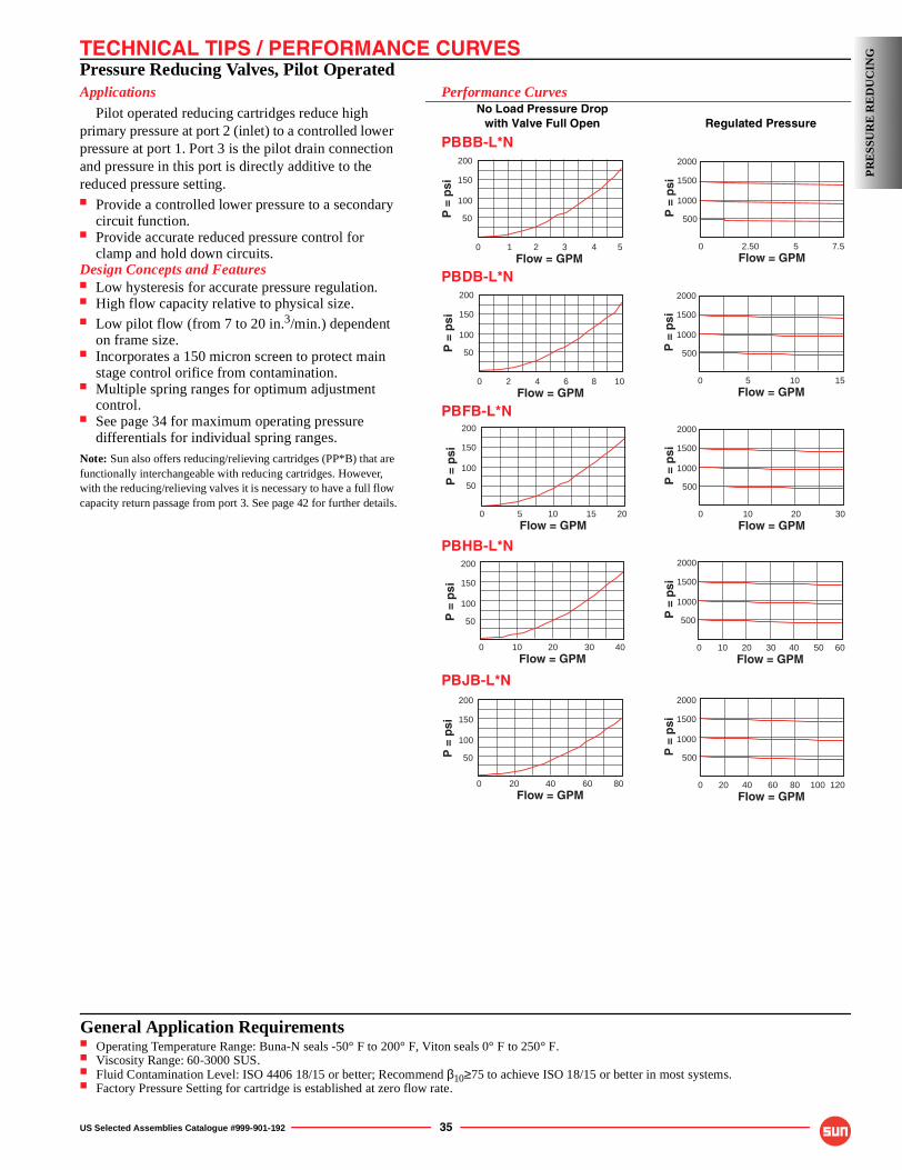
TECHNICAL TIPS / PERFORMANCE CURVES
US Selected Assemblies Catalogue #999-901-192 35
Pressure Reducing Valves, Pilot OperatedApplications
Pilot operated reducing cartridges reduce high primary pressure at port 2 (inlet) to a controlled lower pressure at port 1. Port 3 is the pilot drain connection and pressure in this port is directly additive to the reduced pressure setting.■ Provide a controlled lower pressure to a secondary
circuit function.■ Provide accurate reduced pressure control for
clamp and hold down circuits.Design Concepts and Features■ Low hysteresis for accurate pressure regulation.■ High flow capacity relative to physical size.■ Low pilot flow (from 7 to 20 in.3/min.) dependent
on frame size.■ Incorporates a 150 micron screen to protect main
stage control orifice from contamination.■ Multiple spring ranges for optimum adjustment
control.■ See page 34 for maximum operating pressure
differentials for individual spring ranges.Note: Sun also offers reducing/relieving cartridges (PP*B) that are functionally interchangeable with reducing cartridges. However, with the reducing/relieving valves it is necessary to have a full flow capacity return passage from port 3. See page 42 for further details.
Performance CurvesNo Load Pressure Drop
with Valve Full Open Regulated Pressure
PBBB-L*N
PBDB-L*N
PBFB-L*N
PBHB-L*N
PBJB-L*N
7.5 2.50
2000
1500
1000
0 5Flow = GPM
P =
psi
500
2000
1500
1000
0 15 5 10Flow = GPM
P =
psi
500
30 10 20
2000
1500
1000
0Flow = GPM
P =
psi
500
6040 10 20 30 50
2000
1500
1000
0Flow = GPM
P =
psi
500
120 20 40 60 80 100
2000
1500
1000
0Flow = GPM
P =
psi
500
54
200
150
100
0 1 2 3
50
Flow = GPM
P =
psi
80 20 40 60
200
150
100
0
50
Flow = GPM
P =
psi
205 10 15
200
150
100
0
50
Flow = GPM
P =
psi
40 10 20 30
200
150
100
0
50
Flow = GPM
P =
psi
200
150
100
0 1082 4 6
50
Flow = GPM
P =
psi
PR
ESS
UR
E R
ED
UC
ING
General Application Requirements■ Operating Temperature Range: Buna-N seals -50° F to 200° F, Viton seals 0° F to 250° F.■ Viscosity Range: 60-3000 SUS.■ Fluid Contamination Level: ISO 4406 18/15 or better; Recommend β10≥75 to achieve ISO 18/15 or better in most systems.■ Factory Pressure Setting for cartridge is established at zero flow rate.
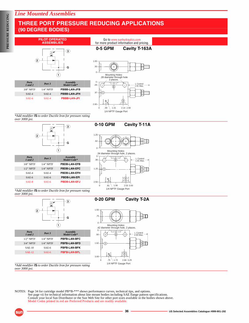
36 US Selected Assemblies Catalogue #999-901-192
Line Mounted Assemblies
THREE PORT PRESSURE REDUCING APPLICATIONS(90 DEGREE BODIES)
PILOT OPERATEDASSEMBLIES
Go to www.sunhydraulics.comfor more product information and pricing.
0-5 GPM Cavity T-163A
Ports1 and 2 Port 3 Assembly
Model Code*
3/8” NPTF 1/4” NPTF PBBB-LAN-JFB
SAE-4 SAE-4 PBBB-LAN-JFH
SAE-6 SAE-4 PBBB-LAN-JFI
*Add modifier /S to order Ductile Iron for pressure rating over 3000 psi.
0-10 GPM Cavity T-11A
Ports1 and 2 Port 3 Assembly
Model Code*
3/8” NPTF 1/4” NPTF PBDB-LAN-EFB
1/2” NPTF 1/4” NPTF PBDB-LAN-EFC
SAE-4 SAE-4 PBDB-LAN-EFH
SAE-6 SAE-6 PBDB-LAN-EFI
SAE-8 SAE-6 PBDB-LAN-EFJ
*Add modifier /S to order Ductile Iron for pressure rating over 3000 psi.
0-20 GPM Cavity T-2A
Ports1 and 2 Port 3 Assembly
Model Code*
1/2” NPTF 1/4” NPTF PBFB-LAN-BFC
3/4” NPTF 1/4” NPTF PBFB-LAN-BFD
SAE-10 SAE-6 PBFB-LAN-BFK
SAE-12 SAE-6 PBFB-LAN-BFL
*Add modifier /S to order Ductile Iron for pressure rating over 3000 psi.
NOTES: Page 34 for cartridge model PB*B-*** shows performance curves, technical tips, and options.See page vii for technical information about line mount bodies including SAE flange pattern specifications.Consult your local Sun Distributor or the Sun Web Site for other port sizes available in the bodies shown above.Model Codes printed in red are Preferred Products and are readily available.
G
2
3
1
L Control1.91 Max.
Mounting Holes:.28 diameter through hole
2 places.
0
0.28
.97
2.00
2.592.141.31
1.00
.50
0
1
2
3
.59
G
1/4 NPTF Gauge Port
G
2
3
1
L Control1.81 Max.
1.25
.62
0
0
0
.38
1.25
2.50
3.002.531.56
Mounting Holes:.34 diameter through hole, 2 places.
1
2
3
.81
G
1/4 NPTF Gauge Port
G
2
3
1
L Control2.00 Max.
Mounting Holes:.42 diameter through hole, 2 places.
0
0
.50
1.62
3.00
3.252.661.72
1.50
.75
0
1
2
3G
.75
1/4 NPTF Gauge Port
PR
ESS
UR
E R
ED
UC
ING
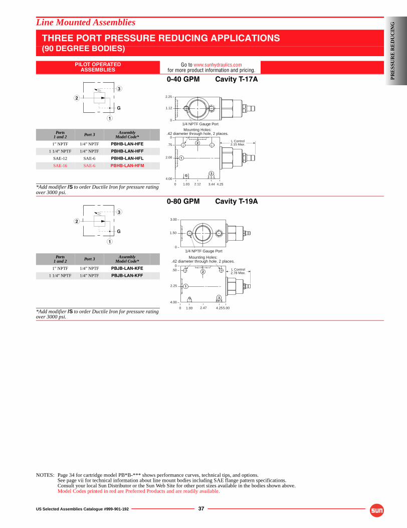
US Selected Assemblies Catalogue #999-901-192 37
Line Mounted Assemblies
THREE PORT PRESSURE REDUCING APPLICATIONS(90 DEGREE BODIES)
PILOT OPERATEDASSEMBLIES
Go to www.sunhydraulics.comfor more product information and pricing.
0-40 GPM Cavity T-17A
Ports1 and 2 Port 3 Assembly
Model Code*
1” NPTF 1/4” NPTF PBHB-LAN-HFE
1 1/4” NPTF 1/4” NPTF PBHB-LAN-HFF
SAE-12 SAE-6 PBHB-LAN-HFL
SAE-16 SAE-6 PBHB-LAN-HFM
*Add modifier /S to order Ductile Iron for pressure rating over 3000 psi.
0-80 GPM Cavity T-19A
Ports1 and 2 Port 3 Assembly
Model Code*
1” NPTF 1/4” NPTF PBJB-LAN-KFE
1 1/4” NPTF 1/4” NPTF PBJB-LAN-KFF
*Add modifier /S to order Ductile Iron for pressure rating over 3000 psi.
NOTES: Page 34 for cartridge model PB*B-*** shows performance curves, technical tips, and options.See page vii for technical information about line mount bodies including SAE flange pattern specifications.Consult your local Sun Distributor or the Sun Web Site for other port sizes available in the bodies shown above.Model Codes printed in red are Preferred Products and are readily available.
3
2
1
G
0
0
.75
2.00
4.00
4.253.442.12
L Control2.15 Max.
Mounting Holes:.42 diameter through hole, 2 places.
2.25
1.12
0
1
2
3G
1.03
1/4 NPTF Gauge Port
3
2
1
G
0
0.50
2.25
4.00
5.004.25
L Control2.78 Max.
Mounting Holes:.42 diameter through hole. 2 places.
3.00
1.50
0
1
2
3G
1/4 NPTF Gauge Port
2.471.00
PR
ESS
UR
E R
ED
UC
ING
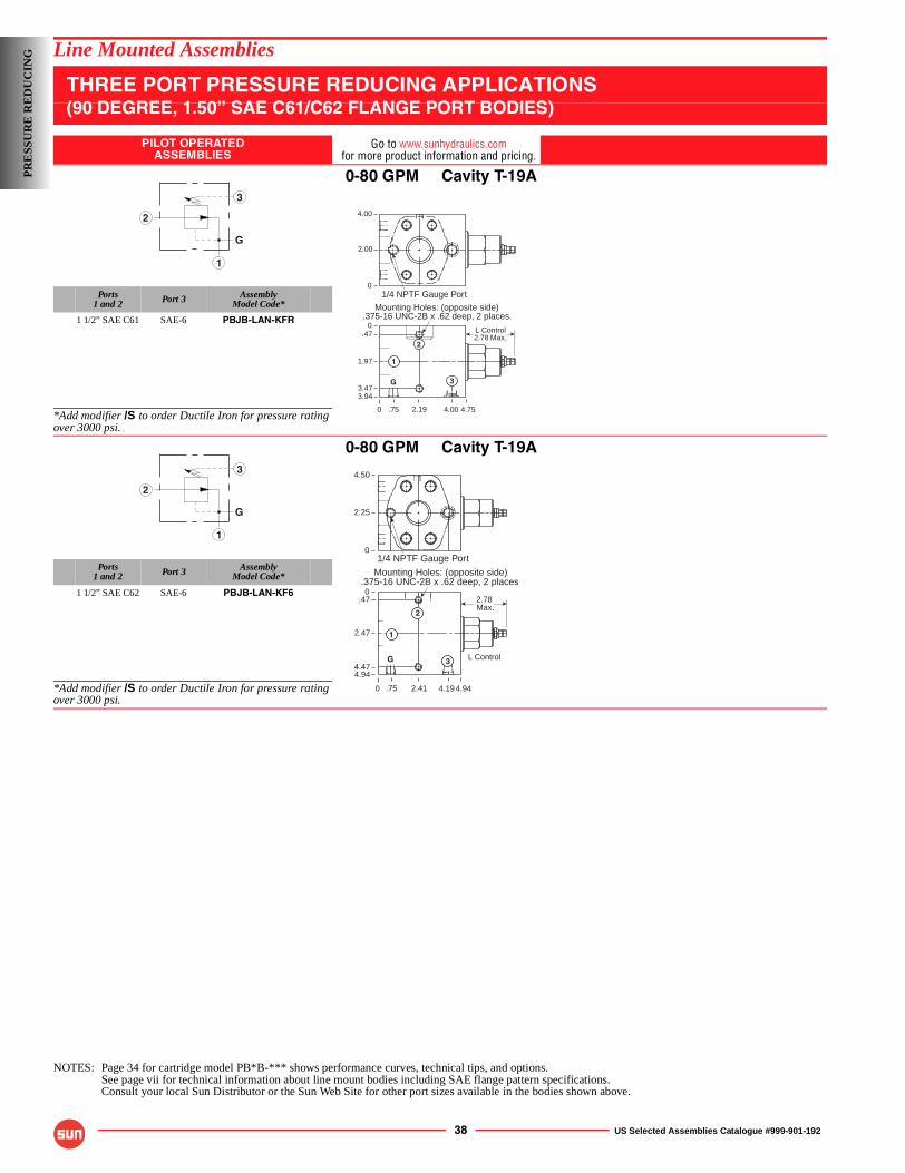
38 US Selected Assemblies Catalogue #999-901-192
Line Mounted Assemblies
THREE PORT PRESSURE REDUCING APPLICATIONS(90 DEGREE, 1.50” SAE C61/C62 FLANGE PORT BODIES)
PILOT OPERATEDASSEMBLIES
Go to www.sunhydraulics.comfor more product information and pricing.
0-80 GPM Cavity T-19A
Ports1 and 2 Port 3 Assembly
Model Code*
1 1/2” SAE C61 SAE-6 PBJB-LAN-KFR
*Add modifier /S to order Ductile Iron for pressure rating over 3000 psi.
0-80 GPM Cavity T-19A
Ports1 and 2 Port 3 Assembly
Model Code*
1 1/2” SAE C62 SAE-6 PBJB-LAN-KF6
*Add modifier /S to order Ductile Iron for pressure rating over 3000 psi.
NOTES: Page 34 for cartridge model PB*B-*** shows performance curves, technical tips, and options.See page vii for technical information about line mount bodies including SAE flange pattern specifications.Consult your local Sun Distributor or the Sun Web Site for other port sizes available in the bodies shown above.
3
2
1
G
0
Mounting Holes: (opposite side).375-16 UNC-2B x .62 deep, 2 places.
0
0
3.94
4.754.00.75
.47 L Control2.78 Max.
2.19
G
1
2
3
4.00
2.00
1.97
3.47
1/4 NPTF Gauge Port
3
2
1
G
0
Mounting Holes: (opposite side).375-16 UNC-2B x .62 deep, 2 places
0
0
4.94
4.944.19.75
.47 2.78 Max.
2.41
G
1
2
3
4.50
2.25
2.47
4.47
1/4 NPTF Gauge Port
L Control
PR
ESS
UR
E R
ED
UC
ING
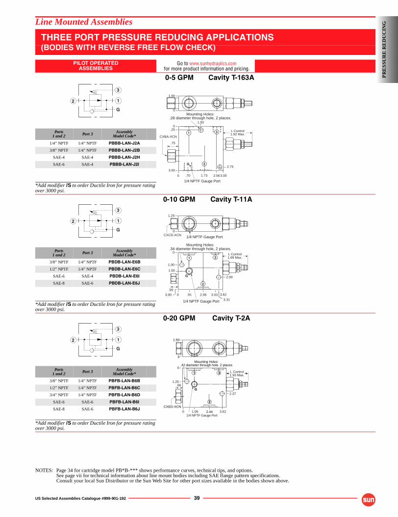
US Selected Assemblies Catalogue #999-901-192 39
Line Mounted Assemblies
THREE PORT PRESSURE REDUCING APPLICATIONS(BODIES WITH REVERSE FREE FLOW CHECK)
PILOT OPERATEDASSEMBLIES
Go to www.sunhydraulics.comfor more product information and pricing.
0-5 GPM Cavity T-163A
Ports1 and 2 Port 3 Assembly
Model Code*
1/4” NPTF 1/4” NPTF PBBB-LAN-J2A
3/8” NPTF 1/4” NPTF PBBB-LAN-J2B
SAE-4 SAE-4 PBBB-LAN-J2H
SAE-6 SAE-4 PBBB-LAN-J2I
*Add modifier /S to order Ductile Iron for pressure rating over 3000 psi.
0-10 GPM Cavity T-11A
Ports1 and 2 Port 3 Assembly
Model Code*
3/8” NPTF 1/4” NPTF PBDB-LAN-E6B
1/2” NPTF 1/4” NPTF PBDB-LAN-E6C
SAE-6 SAE-4 PBDB-LAN-E6I
SAE-8 SAE-6 PBDB-LAN-E6J
*Add modifier /S to order Ductile Iron for pressure rating over 3000 psi.
0-20 GPM Cavity T-2A
Ports1 and 2 Port 3 Assembly
Model Code*
3/8” NPTF 1/4” NPTF PBFB-LAN-B6B
1/2” NPTF 1/4” NPTF PBFB-LAN-B6C
3/4” NPTF 1/4” NPTF PBFB-LAN-B6D
SAE-6 SAE-6 PBFB-LAN-B6I
SAE-8 SAE-6 PBFB-LAN-B6J
*Add modifier /S to order Ductile Iron for pressure rating over 3000 psi.
NOTES: Page 34 for cartridge model PB*B-*** shows performance curves, technical tips, and options.See page vii for technical information about line mount bodies including SAE flange pattern specifications.Consult your local Sun Distributor or the Sun Web Site for other port sizes available in the bodies shown above.
1
3
2
GMounting Holes:
.28 diameter through hole, 2 places.
1.00
0
L Control1.92 Max.
0
0.25
3.00
3.002.561.73.70
CXBA-XCN
G
3
1/4 NPTF Gauge Port
.75
1
22.75
1.50
1
3
2
G
Mounting Holes:.34 diameter through hole, 2 places.
1/4 NPTF Gauge Port
1.25
0
L Control1.69 Max.
0
0
1.00
1.50
3.622.06.91 3.03
G
1
2
3
CXCD-XCN
1/4 NPTF Gauge Port
.59
3.00
2.00
3.31
1
3
2
G
.66
2.44
CXED-XCN
Mounting Holes:.42 diameter through hole. 2 places
1.06 3.620
0
1.25
L Control1.93 Max.
1/4 NPTF Gauge Port
0
1.50
G
31
2
2.37
PR
ESS
UR
E R
ED
UC
ING

40 US Selected Assemblies Catalogue #999-901-192
Line Mounted Assemblies
THREE PORT PRESSURE REDUCING APPLICATIONS(BODIES WITH REVERSE FREE FLOW CHECK)
PILOT OPERATEDASSEMBLIES
Go to www.sunhydraulics.comfor more product information and pricing.
0-40 GPM Cavity T-17A
Ports1 and 2 Port 3 Assembly
Model Code*
1” NPTF 1/4” NPTF PBHB-LAN-H2*
1 1/4” NPTF 1/4” NPTF PBHB-LAN-H2*
SAE-12 SAE-6 PBHB-LAN-H2*
SAE-16 SAE-6 PBHB-LAN-H2*
*Add modifier /S to order Ductile Iron for pressure rating over 3000 psi.
0-80 GPM Cavity T-19A
Ports1 and 2 Port 3 Assembly
Model Code*
1” NPTF 1/4” NPTF PBJB-LAN-KK2*
1 1/4” NPTF 1/4” NPTF PBJB-LAN-KK2*
*Add modifier /S to order Ductile Iron for pressure rating over 3000 psi.
NOTES: Page 34 for cartridge model PB*B shows performance curves, technical tips, and options.See page vii for technical information about line mount bodies including SAE flange pattern specifications.Consult your local Sun Distributor or the Sun Web Site for other port sizes available in the bodies shown above.
1
3
2
G
Mounting Holes:.42 diameter through hole, 2 places.
0
2.50
0
5.00
3.503.12
0
5.503.44 4.752.00.38
CXGD-XCN
G
1 3L Control1.87 Max.
1/4 NPTF Gauge Port
.91
2
5.12
1.50
1.44
1
3
2
G
1.13
Mounting Holes:.42 diameter through hole, 2 places.
G
2.72Max.
0
3.00
0
6.00
4.00
0
7.004.411.88.50 6.22
L Control
1
2
3
CXID-XCN
1/4 NPTF Gauge Port 6.50
1.50
PR
ESS
UR
E R
ED
UC
ING
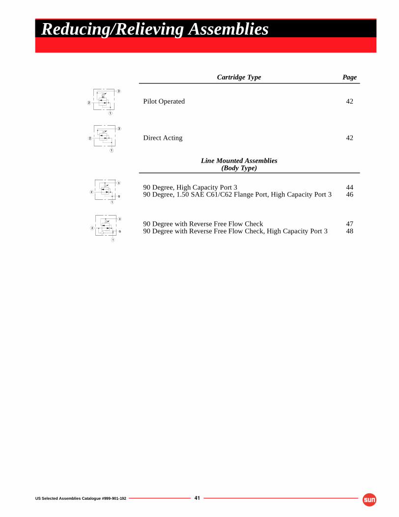
US Selected Assemblies Catalogue #999-901-192 41
Cartridge Type Page
Pilot Operated 42
Direct Acting 42
Line Mounted Assemblies(Body Type)
90 Degree, High Capacity Port 390 Degree, 1.50 SAE C61/C62 Flange Port, High Capacity Port 3
4446
90 Degree with Reverse Free Flow Check90 Degree with Reverse Free Flow Check, High Capacity Port 3
4748
2
3
1
2
3
1
3
G
1
2
3
G
1
2
Reducing/Relieving Assemblies
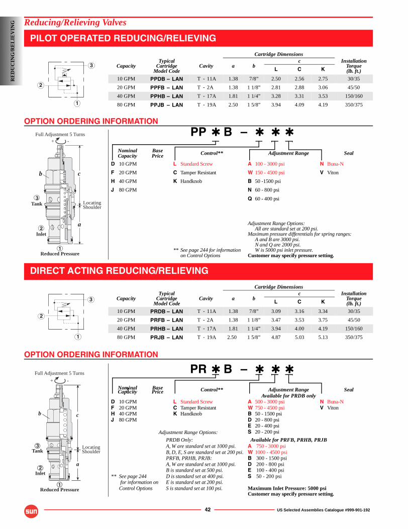
OPTION ORDERING INFORMATION
OPTION ORDERING INFORMATION
42 US Selected Assemblies Catalogue #999-901-192
Reducing/Relieving Valves
PILOT OPERATED REDUCING/RELIEVING
PP ✱ B – ✱ ✱ ✱
Nominal Base Control** Adjustment Range SealCapacity Price
D 10 GPM L Standard Screw A 100 - 3000 psi N Buna-N
F 20 GPM C Tamper Resistant W 150 - 4500 psi V Viton
H 40 GPM K Handknob B 50 -1500 psi
J 80 GPM N 60 - 800 psi
Q 60 - 400 psi
Adjustment Range Options:All are standard set at 200 psi.
Maximum pressure differentials for spring ranges:A and B are 3000 psi.N and Q are 2000 psi.
** See page 244 for information W is 5000 psi inlet pressure.on Control Options Customer may specify pressure setting.
DIRECT ACTING REDUCING/RELIEVING
PR ✱ B – ✱ ✱ ✱
Nominal Base3 Control** Adjustment Range SealCapacity PriceAvailable for PRDB only
D 10 GPM L Standard Screw A 500 - 3000 psi N Buna-NF 20 GPM C Tamper Resistant W 750 - 4500 psi V VitonH 40 GPM K Handknob B 50 - 1500 psiJ 80 GPM D 20 - 800 psi
E 20 - 400 psiAdjustment Range Options: S 20 - 200 psi
PRDB Only: Available for PRFB, PRHB, PRJBA, W are standard set at 1000 psi. A 750 - 3000 psiB, D, E, S are standard set at 200 psi. W 1000 - 4500 psiPRFB, PRHB, PRJB: B 300 - 1500 psiA, W are standard set at 1000 psi. D 200 - 800 psiB is standard set at 500 psi. E 100 - 400 psi
** See page 244 D is standard set at 400 psi. S 50 - 200 psi for information on E is standard set at 200 psi.Control Options S is standard set at 100 psi. Maximum Inlet Pressure: 5000 psi
Customer may specify pressure setting.
Cartridge Dimensions
CapacityTypical
CartridgeModel Code
Cavity a bc Installation
Torque(lb. ft.)L C K
10 GPM PPDB – LAN T - 11A 1.38 7/8” 2.50 2.56 2.75 30/35
20 GPM PPFB – LAN T - 2A 1.38 1 1/8” 2.81 2.88 3.06 45/50
40 GPM PPHB – LAN T - 17A 1.81 1 1/4” 3.28 3.31 3.53 150/160
80 GPM PPJB – LAN T - 19A 2.50 1 5/8” 3.94 4.09 4.19 350/375
Cartridge Dimensions
CapacityTypical
CartridgeModel Code
Cavity a bc Installation
Torque(lb. ft.)L C K
10 GPM PRDB – LAN T - 11A 1.38 7/8” 3.09 3.16 3.34 30/35
20 GPM PRFB – LAN T - 2A 1.38 1 1/8” 3.47 3.53 3.75 45/50
40 GPM PRHB – LAN T - 17A 1.81 1 1/4” 3.94 4.00 4.19 150/160
80 GPM PRJB – LAN T - 19A 2.50 1 5/8” 4.87 5.03 5.13 350/375
2
3
1
-+Full Adjustment 5 Turns
b
3
2
1
c
a
Inlet
Tank
Reduced Pressure
LocatingShoulder
2
3
1
-+
Full Adjustment 5 Turns
b
LocatingShoulder
Reduced Pressure
3
2
1
Tank
Inlet
c
a
RE
DU
CIN
G/R
EL
IEV
ING
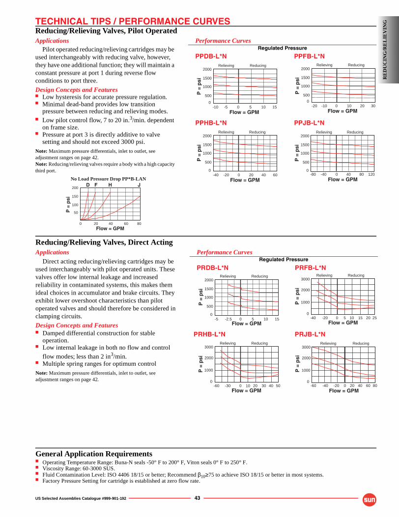
TECHNICAL TIPS / PERFORMANCE CURVES
US Selected Assemblies Catalogue #999-901-192 43
Reducing/Relieving Valves, Pilot OperatedApplications
Pilot operated reducing/relieving cartridges may be used interchangeably with reducing valve, however, they have one additional function; they will maintain a constant pressure at port 1 during reverse flow conditions to port three.
Design Concepts and Features■ Low hysteresis for accurate pressure regulation.■ Minimal dead-band provides low transition
pressure between reducing and relieving modes.■ Low pilot control flow, 7 to 20 in.3/min. dependent
on frame size.■ Pressure at port 3 is directly additive to valve
setting and should not exceed 3000 psi.Note: Maximum pressure differentials, inlet to outlet, see adjustment ranges on page 42.Note: Reducing/relieving valves require a body with a high capacity third port.
Performance CurvesRegulated Pressure
PPDB-L*N PPFB-L*N
PPHB-L*N PPJB-L*N
-10 -5
2000
1500
1000
015
500
Flow = GPM
P =
psi
0 5 10
Relieving Reducing
-40 60-20 4020
2000
1500
1000
0
500
Flow = GPM
P =
psi
0
Relieving Reducing
-80 120-40 8040
2000
1500
1000
0
500
Flow = GPM
P =
psi
0
Relieving Reducing
-20 30-10 2010
2000
1500
1000
0
500
Flow = GPM
P =
psi
0
Relieving Reducing
D F H J200
150
100
0 80 20 40 60
50
Flow = GPM
No Load Pressure Drop PP*B-LAN
P =
psi
RE
DU
CIN
G/R
EL
IEV
ING
Reducing/Relieving Valves, Direct ActingApplications
Direct acting reducing/relieving cartridges may be used interchangeably with pilot operated units. These valves offer low internal leakage and increased reliability in contaminated systems, this makes them ideal choices in accumulator and brake circuits. They exhibit lower overshoot characteristics than pilot operated valves and should therefore be considered in clamping circuits.
Design Concepts and Features■ Damped differential construction for stable
operation.■ Low internal leakage in both no flow and control
flow modes; less than 2 in3/min.■ Multiple spring ranges for optimum controlNote: Maximum pressure differentials, inlet to outlet, see adjustment ranges on page 42.
Performance CurvesRegulated Pressure
PRDB-L*N PRFB-L*N
2000
1500
1000
015 -2.5
500
Flow = GPM
P =
psi
0 5 10
Relieving Reducing
-5
PRHB-L*N
3000
2000
1000
015 -20
Flow = GPM
P =
psi
0 5 10
Relieving Reducing
-40 20 25
3000
2000
1000
030 -30
Flow = GPM
P =
psi
0 20
Relieving Reducing
-60 40 5010
3000
2000
1000
040 -40
Flow = GPM
P =
psi
20
Relieving Reducing
-60 60 800 -20
PRJB-L*N
General Application Requirements■ Operating Temperature Range: Buna-N seals -50° F to 200° F, Viton seals 0° F to 250° F.■ Viscosity Range: 60-3000 SUS.■ Fluid Contamination Level: ISO 4406 18/15 or better; Recommend β10≥75 to achieve ISO 18/15 or better in most systems.■ Factory Pressure Setting for cartridge is established at zero flow rate.
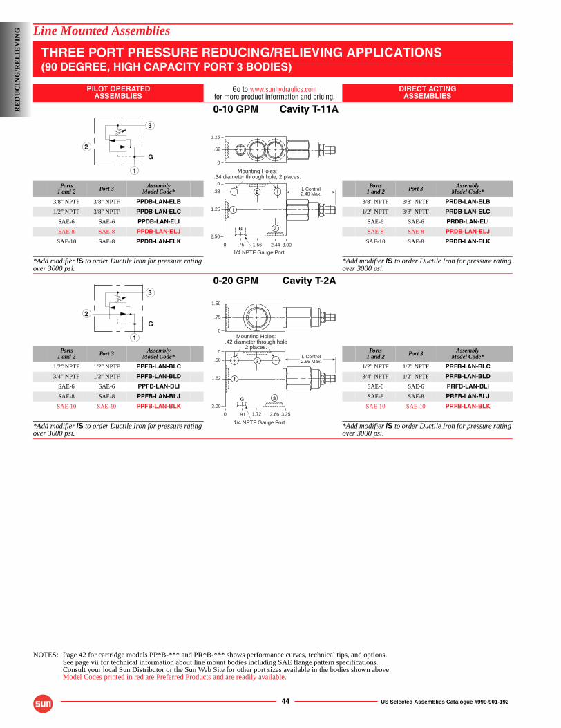
44 US Selected Assemblies Catalogue #999-901-192
Line Mounted Assemblies
THREE PORT PRESSURE REDUCING/RELIEVING APPLICATIONS(90 DEGREE, HIGH CAPACITY PORT 3 BODIES)
PILOT OPERATEDASSEMBLIES
Go to www.sunhydraulics.comfor more product information and pricing.
DIRECT ACTINGASSEMBLIES
0-10 GPM Cavity T-11A
Ports1 and 2 Port 3 Assembly
Model Code*Ports
1 and 2 Port 3 AssemblyModel Code*
3/8” NPTF 3/8” NPTF PPDB-LAN-ELB 3/8” NPTF 3/8” NPTF PRDB-LAN-ELB
1/2” NPTF 3/8” NPTF PPDB-LAN-ELC 1/2” NPTF 3/8” NPTF PRDB-LAN-ELC
SAE-6 SAE-6 PPDB-LAN-ELI SAE-6 SAE-6 PRDB-LAN-ELI
SAE-8 SAE-8 PPDB-LAN-ELJ SAE-8 SAE-8 PRDB-LAN-ELJ
SAE-10 SAE-8 PPDB-LAN-ELK SAE-10 SAE-8 PRDB-LAN-ELK
*Add modifier /S to order Ductile Iron for pressure rating over 3000 psi.
*Add modifier /S to order Ductile Iron for pressure rating over 3000 psi.
0-20 GPM Cavity T-2A
Ports1 and 2 Port 3 Assembly
Model Code*Ports
1 and 2 Port 3 AssemblyModel Code*
1/2” NPTF 1/2” NPTF PPFB-LAN-BLC 1/2” NPTF 1/2” NPTF PRFB-LAN-BLC
3/4” NPTF 1/2” NPTF PPFB-LAN-BLD 3/4” NPTF 1/2” NPTF PRFB-LAN-BLD
SAE-6 SAE-6 PPFB-LAN-BLI SAE-6 SAE-6 PRFB-LAN-BLI
SAE-8 SAE-8 PPFB-LAN-BLJ SAE-8 SAE-8 PRFB-LAN-BLJ
SAE-10 SAE-10 PPFB-LAN-BLK SAE-10 SAE-10 PRFB-LAN-BLK
*Add modifier /S to order Ductile Iron for pressure rating over 3000 psi.
*Add modifier /S to order Ductile Iron for pressure rating over 3000 psi.
NOTES: Page 42 for cartridge models PP*B-*** and PR*B-*** shows performance curves, technical tips, and options.See page vii for technical information about line mount bodies including SAE flange pattern specifications.Consult your local Sun Distributor or the Sun Web Site for other port sizes available in the bodies shown above.Model Codes printed in red are Preferred Products and are readily available.
3
G
1
2
1.25
.62
0
1/4 NPTF Gauge Port
L Control2.40 Max.
Mounting Holes:.34 diameter through hole, 2 places.
0
0
.38
1.25
2.50
3.002.441.56.75
1
2
3G
3
G
1
2
L Control2.66 Max.
1.50
.75
0
0
0
.50
1.62
3.00
3.252.661.72
Mounting Holes:.42 diameter through hole
2 places.
.91
G
1
2
3
1/4 NPTF Gauge Port
RE
DU
CIN
G/R
EL
IEV
ING
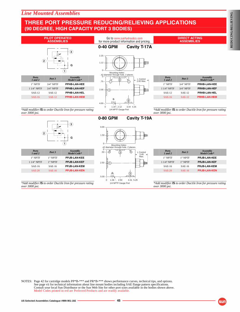
US Selected Assemblies Catalogue #999-901-192 45
Line Mounted Assemblies
THREE PORT PRESSURE REDUCING/RELIEVING APPLICATIONS(90 DEGREE, HIGH CAPACITY PORT 3 BODIES)
PILOT OPERATEDASSEMBLIES
Go to www.sunhydraulics.comfor more product information and pricing.
DIRECT ACTINGASSEMBLIES
0-40 GPM Cavity T-17A
Ports1 and 2 Port 3 Assembly
Model Code*Ports
1 and 2 Port 3 AssemblyModel Code*
1” NPTF 3/4” NPTF PPHB-LAN-HEE 1” NPTF 3/4” NPTF PRHB-LAN-HEE
1 1/4” NPTF 3/4” NPTF PPHB-LAN-HEF 1 1/4” NPTF 3/4” NPTF PRHB-LAN-HEF
SAE-12 SAE-12 PPHB-LAN-HEL SAE-12 SAE-12 PRHB-LAN-HEL
SAE-16 SAE-12 PPHB-LAN-HEM SAE-16 SAE-12 PRHB-LAN-HEM
*Add modifier /S to order Ductile Iron for pressure rating over 3000 psi.
*Add modifier /S to order Ductile Iron for pressure rating over 3000 psi.
0-80 GPM Cavity T-19A
Ports1 and 2 Port 3 Assembly
Model Code*Ports
1 and 2 Port 3 AssemblyModel Code*
1” NPTF 1” NPTF PPJB-LAN-KEE 1” NPTF 1” NPTF PRJB-LAN-KEE
1 1/4” NPTF 1” NPTF PPJB-LAN-KEF 1 1/4” NPTF 1” NPTF PRJB-LAN-KEF
SAE-16 SAE-16 PPJB-LAN-KEM SAE-16 SAE-16 PRJB-LAN-KEM
SAE-20 SAE-16 PPJB-LAN-KEN SAE-20 SAE-16 PRJB-LAN-KEN
*Add modifier /S to order Ductile Iron for pressure rating over 3000 psi.
*Add modifier /S to order Ductile Iron for pressure rating over 3000 psi.
NOTES: Page 42 for cartridge models PP*B-*** and PR*B-*** shows performance curves, technical tips, and options.See page vii for technical information about line mount bodies including SAE flange pattern specifications.Consult your local Sun Distributor or the Sun Web Site for other port sizes available in the bodies shown above.Model Codes printed in red are Preferred Products and are readily available.
3
G
1
2
L Control2.82 Max.
Mounting Holes:.42 diameter through hole, 2 places.
0
0
.75
2.00
4.00
4.253.442.12
2.25
1.12
0
1.19
G
1
2
3
1/4 NPTF Gauge Port
3
G
1
2
0
0.50
2.50
5.00
5.254.312.50
Mounting Holes:.42 diameter through hole, 2 places.
3.00
1.50
0
1.06
G
1
2
3
1/4 NPTF Gauge Port
L Control3.49Max.
RE
DU
CIN
G/R
EL
IEV
ING
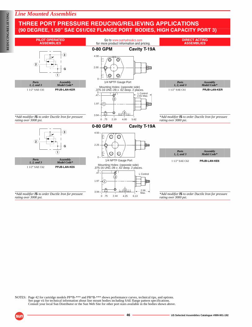
46 US Selected Assemblies Catalogue #999-901-192
Line Mounted Assemblies
THREE PORT PRESSURE REDUCING/RELIEVING APPLICATIONS(90 DEGREE, 1.50” SAE C61/C62 FLANGE PORT BODIES, HIGH CAPACITY PORT 3)
PILOT OPERATEDASSEMBLIES
Go to www.sunhydraulics.comfor more product information and pricing.
DIRECT ACTINGASSEMBLIES
0-80 GPM Cavity T-19A
Ports1, 2, and 3
AssemblyModel Code*
Ports1, 2, and 3
AssemblyModel Code*
1 1/2” SAE C61 PPJB-LAN-KER 1 1/2” SAE C61 PRJB-LAN-KER
*Add modifier /S to order Ductile Iron for pressure rating over 3000 psi.
*Add modifier /S to order Ductile Iron for pressure rating over 3000 psi.
0-80 GPM Cavity T-19A
Ports1, 2, and 3
AssemblyModel Code*
Ports1, 2, and 3
AssemblyModel Code* 1 1/2” SAE C62 PRJB-LAN-KE6
1 1/2” SAE C62 PPJB-LAN-KE6
*Add modifier /S to order Ductile Iron for pressure rating over 3000 psi.
*Add modifier /S to order Ductile Iron for pressure rating over 3000 psi.
NOTES: Page 42 for cartridge models PP*B-*** and PR*B-*** shows performance curves, technical tips, and options.See page vii for technical information about line mount bodies including SAE flange pattern specifications.Consult your local Sun Distributor or the Sun Web Site for other port sizes available in the bodies shown above.
3
G
1
2
0
0.47
1.97
3.94
5.624.002.19
L Control2.81 Max.
Mounting Holes: (opposite side).375-16 UNC-2B x .62 deep. 2 places.
4.00
2.00
01/4 NPTF Gauge Port
G
1
2
3
.75
3
G
1
2
0
0.47
1.97
3.94
6.134.252.44
Mounting Holes: (oppostie side).375-16 UNC-2B x .62 deep. 2 places.
4.50
2.25
01/4 NPTF Gauge Port
G
1
2
3
.75
2.56 Max.
L Control
RE
DU
CIN
G/R
EL
IEV
ING
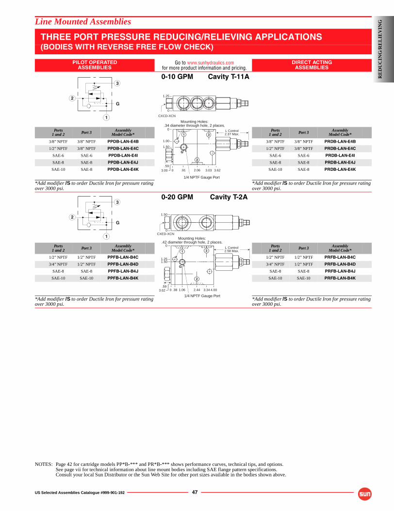
US Selected Assemblies Catalogue #999-901-192 47
Line Mounted Assemblies
THREE PORT PRESSURE REDUCING/RELIEVING APPLICATIONS(BODIES WITH REVERSE FREE FLOW CHECK)
PILOT OPERATEDASSEMBLIES
Go to www.sunhydraulics.comfor more product information and pricing.
DIRECT ACTINGASSEMBLIES
0-10 GPM Cavity T-11A
Ports1 and 2 Port 3 Assembly
Model Code*Ports
1 and 2 Port 3 AssemblyModel Code*
3/8” NPTF 3/8” NPTF PPDB-LAN-E4B 3/8” NPTF 3/8” NPTF PRDB-LAN-E4B
1/2” NPTF 3/8” NPTF PPDB-LAN-E4C 1/2” NPTF 3/8” NPTF PRDB-LAN-E4C
SAE-6 SAE-6 PPDB-LAN-E4I SAE-6 SAE-6 PRDB-LAN-E4I
SAE-8 SAE-8 PPDB-LAN-E4J SAE-8 SAE-8 PRDB-LAN-E4J
SAE-10 SAE-8 PPDB-LAN-E4K SAE-10 SAE-8 PRDB-LAN-E4K
*Add modifier /S to order Ductile Iron for pressure rating over 3000 psi.
*Add modifier /S to order Ductile Iron for pressure rating over 3000 psi.
0-20 GPM Cavity T-2A
Ports1 and 2 Port 3 Assembly
Model Code*Ports
1 and 2 Port 3 AssemblyModel Code*
1/2” NPTF 1/2” NPTF PPFB-LAN-B4C 1/2” NPTF 1/2” NPTF PRFB-LAN-B4C
3/4” NPTF 1/2” NPTF PPFB-LAN-B4D 3/4” NPTF 1/2” NPTF PRFB-LAN-B4D
SAE-8 SAE-8 PPFB-LAN-B4J SAE-8 SAE-8 PRFB-LAN-B4J
SAE-10 SAE-10 PPFB-LAN-B4K SAE-10 SAE-10 PRFB-LAN-B4K
*Add modifier /S to order Ductile Iron for pressure rating over 3000 psi.
*Add modifier /S to order Ductile Iron for pressure rating over 3000 psi.
NOTES: Page 42 for cartridge models PP*B-*** and PR*B-*** shows performance curves, technical tips, and options.See page vii for technical information about line mount bodies including SAE flange pattern specifications.Consult your local Sun Distributor or the Sun Web Site for other port sizes available in the bodies shown above.
3
G
1
2
.59
Mounting Holes:.34 diameter through hole, 2 places.
1.25
0
L Control2.37 Max.
0
0
1.00
3.00 3.623.032.06.91
CXCD-XCN
1/4 NPTF Gauge Port
G
1
2
3
1.50
3
G
1
2
Mounting Holes:.42 diameter through hole, 2 places.
1.50
0
L Control2.58 Max.
0
0
1.50
4.003.342.44.38
CXED-XCN
1.06
1.25
1/4 NPTF Gauge Port
G
.593.62
2
1 3
RE
DU
CIN
G/R
EL
IEV
ING
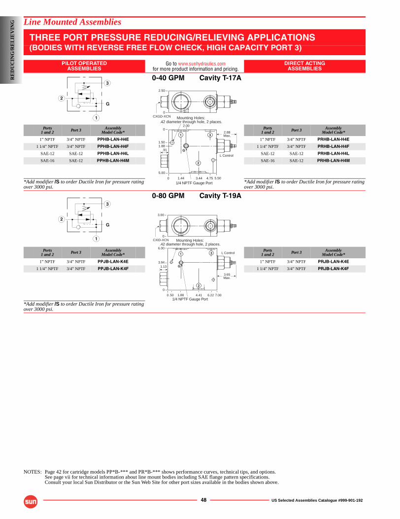
48 US Selected Assemblies Catalogue #999-901-192
Line Mounted Assemblies
THREE PORT PRESSURE REDUCING/RELIEVING APPLICATIONS(BODIES WITH REVERSE FREE FLOW CHECK, HIGH CAPACITY PORT 3)
PILOT OPERATEDASSEMBLIES
Go to www.sunhydraulics.comfor more product information and pricing.
DIRECT ACTINGASSEMBLIES
0-40 GPM Cavity T-17A
Ports1 and 2 Port 3 Assembly
Model Code*Ports
1 and 2 Port 3 AssemblyModel Code*
1” NPTF 3/4” NPTF PPHB-LAN-H4E 1” NPTF 3/4” NPTF PRHB-LAN-H4E
1 1/4” NPTF 3/4” NPTF PPHB-LAN-H4F 1 1/4” NPTF 3/4” NPTF PRHB-LAN-H4F
SAE-12 SAE-12 PPHB-LAN-H4L SAE-12 SAE-12 PRHB-LAN-H4L
SAE-16 SAE-12 PPHB-LAN-H4M SAE-16 SAE-12 PRHB-LAN-H4M
*Add modifier /S to order Ductile Iron for pressure rating over 3000 psi.
*Add modifier /S to order Ductile Iron for pressure rating over 3000 psi.
0-80 GPM Cavity T-19A
Ports1 and 2 Port 3 Assembly
Model Code*Ports
1 and 2 Port 3 AssemblyModel Code*
1” NPTF 3/4” NPTF PPJB-LAN-K4E 1” NPTF 3/4” NPTF PRJB-LAN-K4E
1 1/4” NPTF 3/4” NPTF PPJB-LAN-K4F 1 1/4” NPTF 3/4” NPTF PRJB-LAN-K4F
*Add modifier /S to order Ductile Iron for pressure rating over 3000 psi.
NOTES: Page 42 for cartridge models PP*B-*** and PR*B-*** shows performance curves, technical tips, and options.See page vii for technical information about line mount bodies including SAE flange pattern specifications.Consult your local Sun Distributor or the Sun Web Site for other port sizes available in the bodies shown above.
3
G
1
2
.91
Mounting Holes:.42 diameter through hole, 2 places.
1/4 NPTF Gauge Port
2.50
0
2.88 Max.
0
0
1.501.88
5.00
5.503.441.44 4.75
CXGD-XCN
G
1
2
3
L Control
2.00
3
G
1
2
Mounting Holes:.42 diameter through hole, 2 places.
1/4 NPTF Gauge Port
G
0
6.00
3.94
0
7.004.41.50 6.221.88
1
2
3
1.13
3.65 Max.
L Control
0
3.00
CXID-XCN
RE
DU
CIN
G/R
EL
IEV
ING
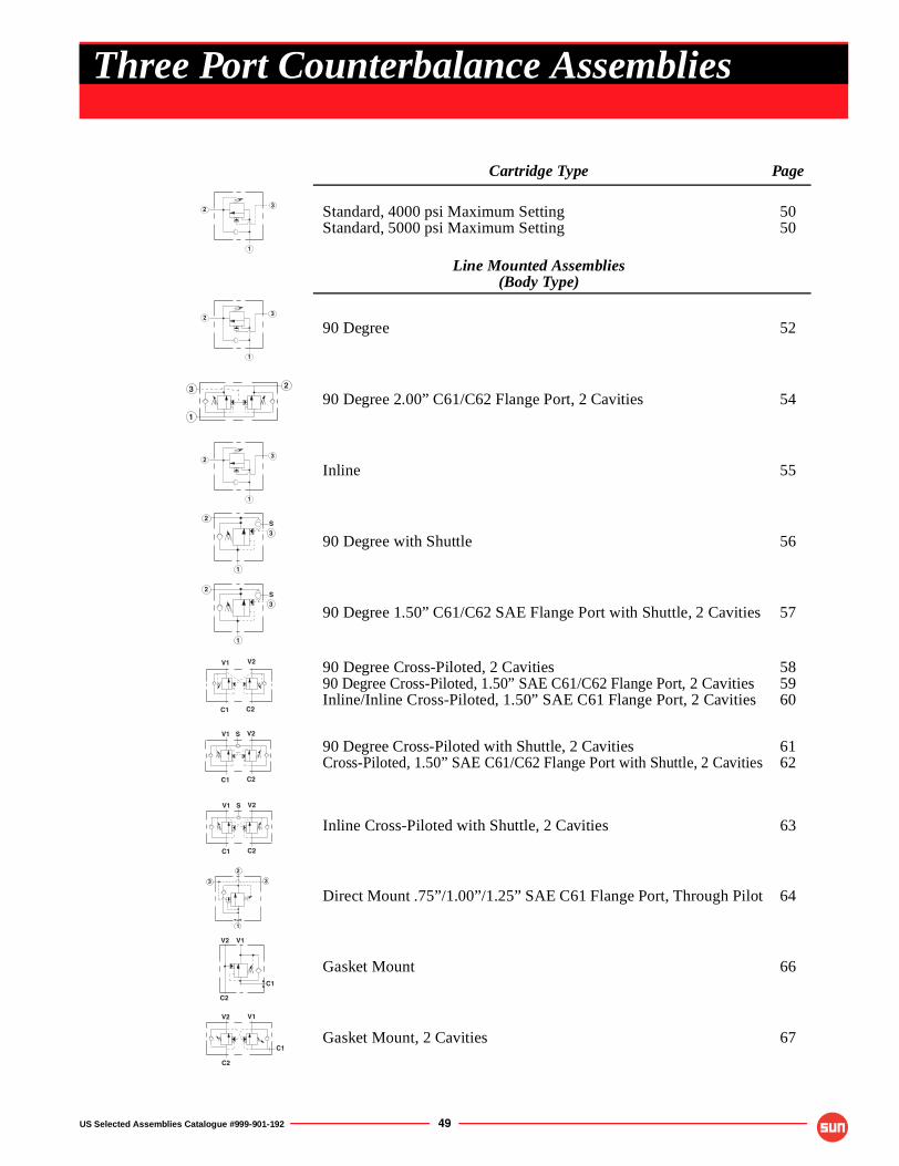
US Selected Assemblies Catalogue #999-901-192 49
Cartridge Type Page
Standard, 4000 psi Maximum SettingStandard, 5000 psi Maximum Setting
5050
Line Mounted Assemblies(Body Type)
90 Degree 52
90 Degree 2.00” C61/C62 Flange Port, 2 Cavities 54
Inline 55
90 Degree with Shuttle 56
90 Degree 1.50” C61/C62 SAE Flange Port with Shuttle, 2 Cavities 57
90 Degree Cross-Piloted, 2 Cavities90 Degree Cross-Piloted, 1.50” SAE C61/C62 Flange Port, 2 CavitiesInline/Inline Cross-Piloted, 1.50” SAE C61 Flange Port, 2 Cavities
585960
90 Degree Cross-Piloted with Shuttle, 2 CavitiesCross-Piloted, 1.50” SAE C61/C62 Flange Port with Shuttle, 2 Cavities
6162
Inline Cross-Piloted with Shuttle, 2 Cavities 63
Direct Mount .75”/1.00”/1.25” SAE C61 Flange Port, Through Pilot 64
Gasket Mount 66
Gasket Mount, 2 Cavities 67
1
23
1
23
3
1
2
1
23
S3
1
2
S3
1
2
V1 V2
C1 C2
V1 V2
C1 C2
S
V1 V2
C1 C2
S
3
2
3
1
V2 V1
C1
C2
V2 V1
C2
C1
Three Port Counterbalance Assemblies
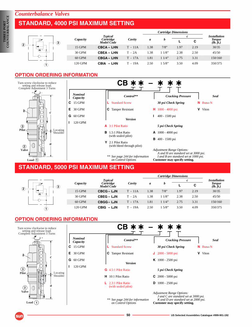
OPTION ORDERING INFORMATION
OPTION ORDERING INFORMATION
50 US Selected Assemblies Catalogue #999-901-192
Counterbalance Valves
STANDARD, 4000 PSI MAXIMUM SETTING
CB ✱ ✱ – ✱ ✱ ✱
Nominal Control** Cracking Pressure SealCapacity
C 15 GPM L Standard Screw 30 psi Check Spring N Buna-N
E 30 GPM C Tamper Resistant H 1000 - 4000 psi V Viton
G 60 GPM I 400 - 1500 psiVersion
I 120 GPMA 3:1 Pilot Ratio 5 psi Check Spring
B 1.5:1 Pilot Ratio A 1000 - 4000 psi(with sealed pilot)
B 400 - 1500 psiY 2:1 Pilot Ratio
(with bleed through pilot)Adjustment Range Options:
A and H are standard set at 3000 psi.** See page 244 for information I and B are standard set at 1000 psi.
on Control Options Customer may specify setting.
STANDARD, 5000 PSI MAXIMUM SETTING
CB ✱ ✱ – ✱ ✱ ✱
Nominal Control** Cracking Pressure SealCapacity
C 15 GPM L Standard Screw 30 psi Check Spring N Buna-N
E 30 GPM C Tamper Resistant J 2000 - 5000 psi V Viton
G 60 GPM K 1000 - 2500 psiVersion
I 120 GPMG 4.5:1 Pilot Ratio 5 psi Check Spring
H 10:1 Pilot Ratio C 2000 - 5000 psi
L 2.3:1 Pilot Ratio D 1000 - 2500 psi(with sealed pilot)
Adjustment Range Options:J and C are standard set at 3000 psi.
** See page 244 for information K and D are standard set at 2000 psi.on Control Options Customer may specify setting.
Cartridge Dimensions
CapacityTypical
CartridgeModel Code
Cavity a bc Installation
Torque(lb. ft.)L C
15 GPM CBCA – LHN T - 11A 1.38 7/8” 1.97 2.19 30/35
30 GPM CBEA – LHN T - 2A 1.38 1 1/8” 2.38 2.50 45/50
60 GPM CBGA – LHN T - 17A 1.81 1 1/4” 2.75 3.31 150/160
120 GPM CBIA – LHN T - 19A 2.50 1 5/8” 3.50 4.09 350/375
Cartridge Dimensions
CapacityTypical
CartridgeModel Code
Cavity a bc Installation
Torque(lb. ft.)L C
15 GPM CBCG – LJN T - 11A 1.38 7/8” 1.97 2.19 30/35
30 GPM CBEG – LJN T - 2A 1.38 1 1/8” 2.38 2.50 45/50
60 GPM CBGG– LJN T - 17A 1.81 1 1/4” 2.75 3.31 150/160
120 GPM CBIG – LJN T - 19A 2.50 1 5/8” 3.50 4.09 350/375
1
23
c
a
Load
Valve
Pilot LocatingShoulder
Turn screw clockwise to reducesetting and release load.
Complete Adjustment 3 Turns
-+
b
3
2
1
1
23
Load
LocatingShoulder
- +
3
Turn screw clockwise to reducesetting and release load.
Complete Adjustment 3 Turns
Pilot
Valve
c
a2
1
b
TH
RE
E P
OR
TC
OU
NT
ER
BA
LA
NC
E
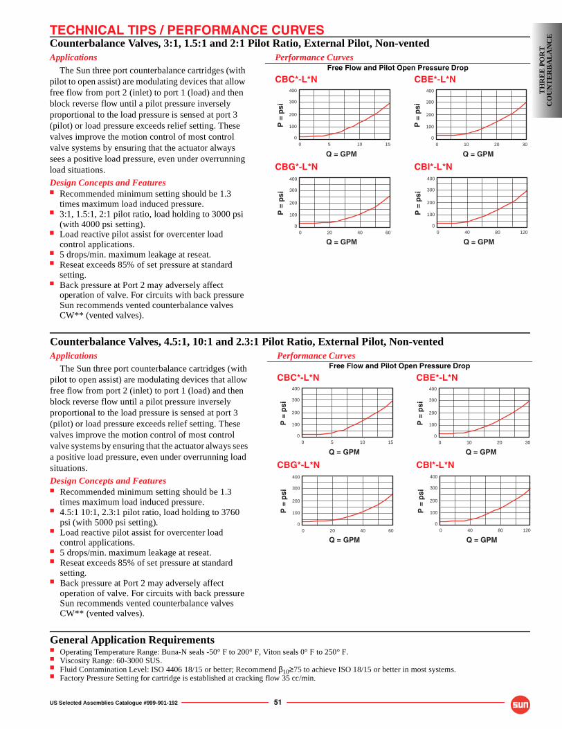
TECHNICAL TIPS / PERFORMANCE CURVES
US Selected Assemblies Catalogue #999-901-192 51
Counterbalance Valves, 3:1, 1.5:1 and 2:1 Pilot Ratio, External Pilot, Non-ventedApplications
The Sun three port counterbalance cartridges (with pilot to open assist) are modulating devices that allow free flow from port 2 (inlet) to port 1 (load) and then block reverse flow until a pilot pressure inversely proportional to the load pressure is sensed at port 3 (pilot) or load pressure exceeds relief setting. These valves improve the motion control of most control valve systems by ensuring that the actuator always sees a positive load pressure, even under overrunning load situations.
Design Concepts and Features■ Recommended minimum setting should be 1.3
times maximum load induced pressure.■ 3:1, 1.5:1, 2:1 pilot ratio, load holding to 3000 psi
(with 4000 psi setting).■ Load reactive pilot assist for overcenter load
control applications.■ 5 drops/min. maximum leakage at reseat.■ Reseat exceeds 85% of set pressure at standard
setting.■ Back pressure at Port 2 may adversely affect
operation of valve. For circuits with back pressure Sun recommends vented counterbalance valves CW** (vented valves).
Performance CurvesFree Flow and Pilot Open Pressure Drop
CBC*-L*N CBE*-L*N
CBG*-L*N CBI*-L*N
P =
psi
Q = GPM400
400
100
200
06020
300
P =
psi
Q = GPM800
400
100
200
012040
300
P =
psi
Q = GPM100
400
100
200
0155
300
P =
psi
Q = GPM200
400
100
200
03010
300
TH
RE
E P
OR
TC
OU
NT
ER
BA
LA
NC
E
Counterbalance Valves, 4.5:1, 10:1 and 2.3:1 Pilot Ratio, External Pilot, Non-ventedApplications
The Sun three port counterbalance cartridges (with pilot to open assist) are modulating devices that allow free flow from port 2 (inlet) to port 1 (load) and then block reverse flow until a pilot pressure inversely proportional to the load pressure is sensed at port 3 (pilot) or load pressure exceeds relief setting. These valves improve the motion control of most control valve systems by ensuring that the actuator always sees a positive load pressure, even under overrunning load situations.
Design Concepts and Features■ Recommended minimum setting should be 1.3
times maximum load induced pressure.■ 4.5:1 10:1, 2.3:1 pilot ratio, load holding to 3760
psi (with 5000 psi setting).■ Load reactive pilot assist for overcenter load
control applications.■ 5 drops/min. maximum leakage at reseat.■ Reseat exceeds 85% of set pressure at standard
setting.■ Back pressure at Port 2 may adversely affect
operation of valve. For circuits with back pressure Sun recommends vented counterbalance valves CW** (vented valves).
Performance CurvesFree Flow and Pilot Open Pressure Drop
CBC*-L*N CBE*-L*N
CBG*-L*N CBI*-L*N
P =
psi
Q = GPM400
400
100
200
06020
300
P =
psi
Q = GPM800
400
100
200
012040
300
P =
psi
Q = GPM100
400
100
200
0155
300
P =
psi
Q = GPM200
400
100
200
03010
300
General Application Requirements■ Operating Temperature Range: Buna-N seals -50° F to 200° F, Viton seals 0° F to 250° F.■ Viscosity Range: 60-3000 SUS.■ Fluid Contamination Level: ISO 4406 18/15 or better; Recommend β10≥75 to achieve ISO 18/15 or better in most systems.■ Factory Pressure Setting for cartridge is established at cracking flow 35 cc/min.
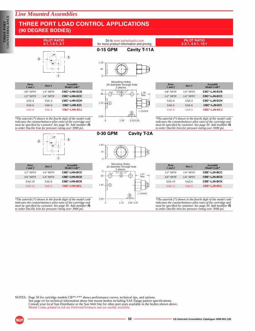
52 US Selected Assemblies Catalogue #999-901-192
Line Mounted Assemblies
THREE PORT LOAD CONTROL APPLICATIONS(90 DEGREE BODIES)
PILOT RATIO3:1, 1.5:1, 2:1
Go to www.sunhydraulics.comfor more product information and pricing.
PILOT RATIO2.3:1, 4.5:1, 10:1
0-15 GPM Cavity T-11A
Ports1 and 2 Port 3 Assembly
Model Code*Ports
1 and 2 Port 3 AssemblyModel Code*
3/8” NPTF 1/4” NPTF CBC*-LHN-ECB 3/8” NPTF 1/4” NPTF CBC*-LJN-ECB
1/2” NPTF 1/4” NPTF CBC*-LHN-ECC 1/2” NPTF 1/4” NPTF CBC*-LJN-ECC
SAE-4 SAE-4 CBC*-LHN-ECH SAE-4 SAE-4 CBC*-LJN-ECH
SAE-6 SAE-6 CBC*-LHN-ECI SAE-6 SAE-6 CBC*-LJN-ECI
SAE-8 SAE-6 CBC*-LHN-ECJ SAE-8 SAE-6 CBC*-LJN-ECJ
*The asterisk (*) shown in the fourth digit of the model code indicates the counterbalance pilot ratio of the cartridge and must be specified by customer. See page 50. Add modifier /Sto order Ductile Iron for pressure rating over 3000 psi.
*The asterisk (*) shown in the fourth digit of the model code indicates the counterbalance pilot ratio of the cartridge and must be specified by customer. See page 50. Add modifier /Sto order Ductile Iron for pressure rating over 3000 psi.
0-30 GPM Cavity T-2A
Ports1 and 2 Port 3 Assembly
Model Code*Ports
1 and 2 Port 3 AssemblyModel Code*
1/2” NPTF 1/4” NPTF CBE*-LHN-BCC 1/2” NPTF 1/4” NPTF CBE*-LJN-BCC
3/4” NPTF 1/4” NPTF CBE*-LHN-BCD 3/4” NPTF 1/4” NPTF CBE*-LJN-BCD
SAE-10 SAE-6 CBE*-LHN-BCK SAE-10 SAE-6 CBE*-LJN-BCK
SAE-12 SAE-6 CBE*-LHN-BCL SAE-12 SAE-6 CBE*-LJN-BCL
*The asterisk (*) shown in the fourth digit of the model code indicates the counterbalance pilot ratio of the cartridge and must be specified by customer. See page 50. Add modifier /Sto order Ductile Iron for pressure rating over 3000 psi.
*The asterisk (*) shown in the fourth digit of the model code indicates the counterbalance pilot ratio of the cartridge and must be specified by customer. See page 50. Add modifier /Sto order Ductile Iron for pressure rating over 3000 psi.
NOTES: Page 50 for cartridge models CB**-*** shows performance curves, technical tips, and options.See page vii for technical information about line mount bodies including SAE flange pattern specifications.Consult your local Sun Distributor or the Sun Web Site for other port sizes available in the bodies shown above.Model Codes printed in red are Preferred Products and are readily available.
1
23
1.28 Max.
1.25
.62
0
0
0
.38
1.25
2.50
3.002.531.56
Mounting Holes:.34 diameter through hole
2 places.
L Control
1
2
3
1
23
1.57 Max.
Mounting Holes:.42 diameter through hole
2 places.
0
0
.50
1.62
3.00
3.252.661.72
1.50
.75
0
L Control3
1
2
TH
RE
E P
OR
TC
OU
NT
ER
BA
LA
NC
E
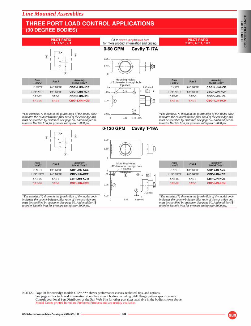
US Selected Assemblies Catalogue #999-901-192 53
Line Mounted Assemblies
THREE PORT LOAD CONTROL APPLICATIONS(90 DEGREE BODIES)
PILOT RATIO3:1, 1.5:1, 2:1
Go to www.sunhydraulics.comfor more product information and pricing.
PILOT RATIO2.3:1, 4.5:1, 10:1
0-60 GPM Cavity T-17A
Ports1 and 2 Port 3 Assembly
Model Code*Ports
1 and 2 Port 3 AssemblyModel Code*
1” NPTF 1/4” NPTF CBG*-LHN-HCE 1” NPTF 1/4” NPTF CBG*-LJN-HCE
1 1/4” NPTF 1/4” NPTF CBG*-LHN-HCF 1 1/4” NPTF 1/4” NPTF CBG*-LJN-HCF
SAE-12 SAE-6 CBG*-LHN-HCL SAE-12 SAE-6 CBG*-LJN-HCL
SAE-16 SAE-6 CBG*-LHN-HCM SAE-16 SAE-6 CBG*-LJN-HCM
*The asterisk (*) shown in the fourth digit of the model code indicates the counterbalance pilot ratio of the cartridge and must be specified by customer. See page 50. Add modifier /Sto order Ductile Iron for pressure rating over 3000 psi.
*The asterisk (*) shown in the fourth digit of the model code indicates the counterbalance pilot ratio of the cartridge and must be specified by customer. See page 50. Add modifier /Sto order Ductile Iron for pressure rating over 3000 psi.
0-120 GPM Cavity T-19A
Ports1 and 2 Port 3 Assembly
Model Code*Ports
1 and 2 Port 3 AssemblyModel Code*
1” NPTF 1/4” NPTF CBI*-LHN-KCE 1” NPTF 1/4” NPTF CBI*-LJN-KCE
1 1/4” NPTF 1/4” NPTF CBI*-LHN-KCF 1 1/4” NPTF 1/4” NPTF CBI*-LJN-KCF
SAE-16 SAE-6 CBI*-LHN-KCM SAE-16 SAE-6 CBI*-LJN-KCM
SAE-20 SAE-6 CBI*-LHN-KCN SAE-20 SAE-6 CBI*-LJN-KCN
*The asterisk (*) shown in the fourth digit of the model code indicates the counterbalance pilot ratio of the cartridge and must be specified by customer. See page 50. Add modifier /Sto order Ductile Iron for pressure rating over 3000 psi.
*The asterisk (*) shown in the fourth digit of the model code indicates the counterbalance pilot ratio of the cartridge and must be specified by customer. See page 50. Add modifier /Sto order Ductile Iron for pressure rating over 3000 psi.
NOTES: Page 50 for cartridge models CB**-*** shows performance curves, technical tips, and options.See page vii for technical information about line mount bodies including SAE flange pattern specifications.Consult your local Sun Distributor or the Sun Web Site for other port sizes available in the bodies shown above.Model Codes printed in red are Preferred Products and are readily available.
1
23
0
0
.75
2.00
4.00
4.253.502.12
2.61 Max.
Mounting Holes:.42 diameter through hole
2 places.
2.25
2.12
0
L Control
1
2
3
1
23
0
0.50
2.25
4.00
5.004.252.47
2.34 Max.
Mounting Holes:.42 diameter through hole
2 places.
3.00
1.50
0
L Control
1
2
3
TH
RE
E P
OR
TC
OU
NT
ER
BA
LA
NC
E
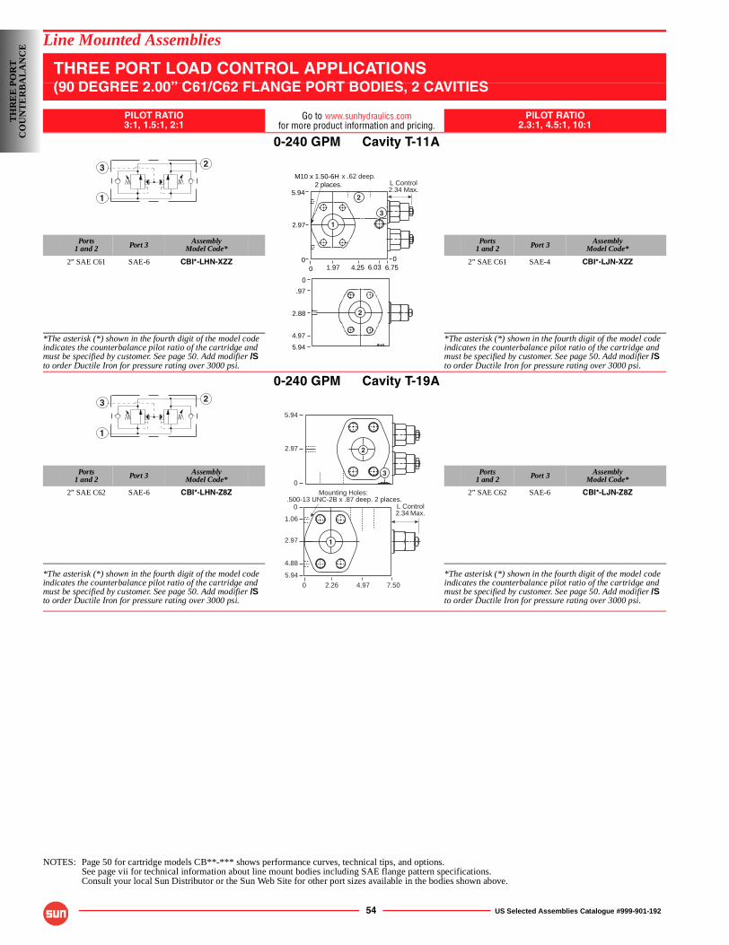
54 US Selected Assemblies Catalogue #999-901-192
Line Mounted Assemblies
THREE PORT LOAD CONTROL APPLICATIONS(90 DEGREE 2.00” C61/C62 FLANGE PORT BODIES, 2 CAVITIES
PILOT RATIO3:1, 1.5:1, 2:1
Go to www.sunhydraulics.comfor more product information and pricing.
PILOT RATIO2.3:1, 4.5:1, 10:1
0-240 GPM Cavity T-11A
Ports1 and 2 Port 3 Assembly
Model Code*Ports
1 and 2 Port 3 AssemblyModel Code*
2” SAE C61 SAE-6 CBI*-LHN-XZZ 2” SAE C61 SAE-4 CBI*-LJN-XZZ
*The asterisk (*) shown in the fourth digit of the model code indicates the counterbalance pilot ratio of the cartridge and must be specified by customer. See page 50. Add modifier /Sto order Ductile Iron for pressure rating over 3000 psi.
*The asterisk (*) shown in the fourth digit of the model code indicates the counterbalance pilot ratio of the cartridge and must be specified by customer. See page 50. Add modifier /Sto order Ductile Iron for pressure rating over 3000 psi.
0-240 GPM Cavity T-19A
Ports1 and 2 Port 3 Assembly
Model Code*Ports
1 and 2 Port 3 AssemblyModel Code*
2” SAE C62 SAE-6 CBI*-LHN-Z8Z 2” SAE C62 SAE-6 CBI*-LJN-Z8Z
*The asterisk (*) shown in the fourth digit of the model code indicates the counterbalance pilot ratio of the cartridge and must be specified by customer. See page 50. Add modifier /Sto order Ductile Iron for pressure rating over 3000 psi.
*The asterisk (*) shown in the fourth digit of the model code indicates the counterbalance pilot ratio of the cartridge and must be specified by customer. See page 50. Add modifier /Sto order Ductile Iron for pressure rating over 3000 psi.
NOTES: Page 50 for cartridge models CB**-*** shows performance curves, technical tips, and options.See page vii for technical information about line mount bodies including SAE flange pattern specifications.Consult your local Sun Distributor or the Sun Web Site for other port sizes available in the bodies shown above.
3
1
2
0 6.754.251.97 6.030 0
2.97
5.942 places. L Control
2.34 Max.
M10 x 1.50-6H x .62 deep.
4.97
0
.97
2.88
5.94
1
2
3
2
3
1
2
5.94
2.97
0
L Control2.34 Max.
Mounting Holes:.500-13 UNC-2B x .87 deep. 2 places.
0
0
1.06
2.97
5.94
4.972.26
4.88
7.50
2
3
1
TH
RE
E P
OR
TC
OU
NT
ER
BA
LA
NC
E
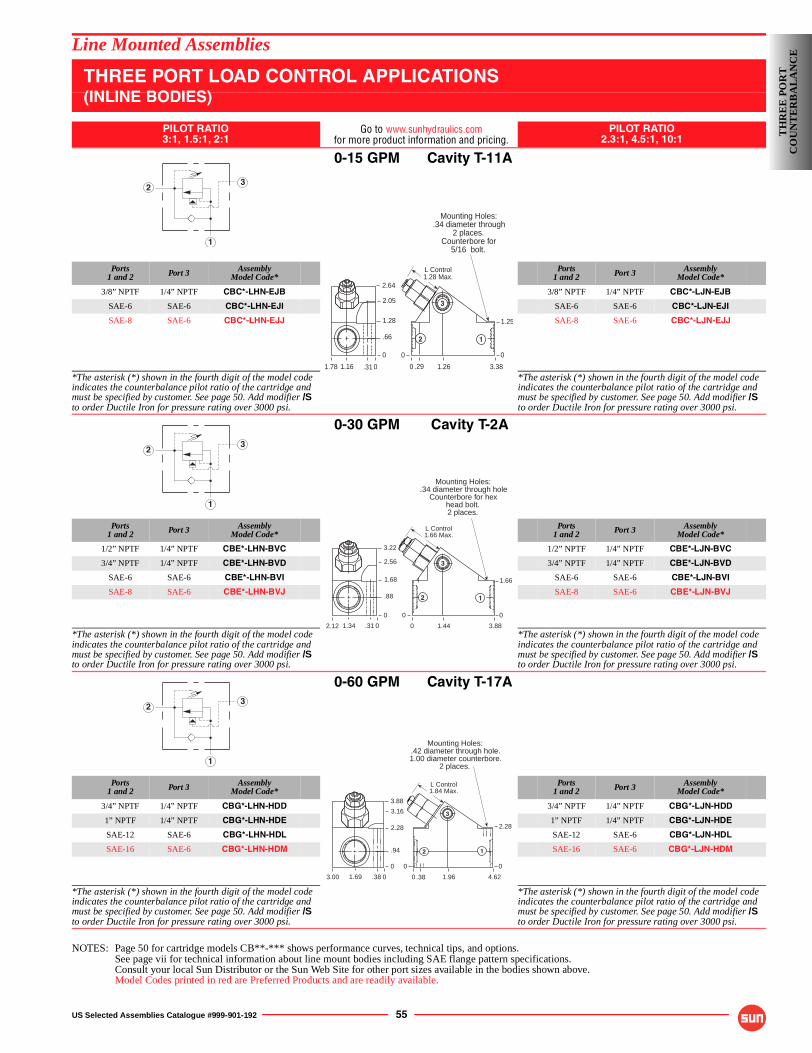
US Selected Assemblies Catalogue #999-901-192 55
Line Mounted Assemblies
THREE PORT LOAD CONTROL APPLICATIONS(INLINE BODIES)
PILOT RATIO3:1, 1.5:1, 2:1
Go to www.sunhydraulics.comfor more product information and pricing.
PILOT RATIO2.3:1, 4.5:1, 10:1
0-15 GPM Cavity T-11A
Ports1 and 2 Port 3 Assembly
Model Code*Ports
1 and 2 Port 3 AssemblyModel Code*
3/8” NPTF 1/4” NPTF CBC*-LHN-EJB 3/8” NPTF 1/4” NPTF CBC*-LJN-EJB
SAE-6 SAE-6 CBC*-LHN-EJI SAE-6 SAE-6 CBC*-LJN-EJI
SAE-8 SAE-6 CBC*-LHN-EJJ SAE-8 SAE-6 CBC*-LJN-EJJ
*The asterisk (*) shown in the fourth digit of the model code indicates the counterbalance pilot ratio of the cartridge and must be specified by customer. See page 50. Add modifier /Sto order Ductile Iron for pressure rating over 3000 psi.
*The asterisk (*) shown in the fourth digit of the model code indicates the counterbalance pilot ratio of the cartridge and must be specified by customer. See page 50. Add modifier /Sto order Ductile Iron for pressure rating over 3000 psi.
0-30 GPM Cavity T-2A
Ports1 and 2 Port 3 Assembly
Model Code*Ports
1 and 2 Port 3 AssemblyModel Code*
1/2” NPTF 1/4” NPTF CBE*-LHN-BVC 1/2” NPTF 1/4” NPTF CBE*-LJN-BVC
3/4” NPTF 1/4” NPTF CBE*-LHN-BVD 3/4” NPTF 1/4” NPTF CBE*-LJN-BVD
SAE-6 SAE-6 CBE*-LHN-BVI SAE-6 SAE-6 CBE*-LJN-BVI
SAE-8 SAE-6 CBE*-LHN-BVJ SAE-8 SAE-6 CBE*-LJN-BVJ
*The asterisk (*) shown in the fourth digit of the model code indicates the counterbalance pilot ratio of the cartridge and must be specified by customer. See page 50. Add modifier /Sto order Ductile Iron for pressure rating over 3000 psi.
*The asterisk (*) shown in the fourth digit of the model code indicates the counterbalance pilot ratio of the cartridge and must be specified by customer. See page 50. Add modifier /Sto order Ductile Iron for pressure rating over 3000 psi.
0-60 GPM Cavity T-17A
Ports1 and 2 Port 3 Assembly
Model Code*Ports
1 and 2 Port 3 AssemblyModel Code*
3/4” NPTF 1/4” NPTF CBG*-LHN-HDD 3/4” NPTF 1/4” NPTF CBG*-LJN-HDD
1” NPTF 1/4” NPTF CBG*-LHN-HDE 1” NPTF 1/4” NPTF CBG*-LJN-HDE
SAE-12 SAE-6 CBG*-LHN-HDL SAE-12 SAE-6 CBG*-LJN-HDL
SAE-16 SAE-6 CBG*-LHN-HDM SAE-16 SAE-6 CBG*-LJN-HDM
*The asterisk (*) shown in the fourth digit of the model code indicates the counterbalance pilot ratio of the cartridge and must be specified by customer. See page 50. Add modifier /Sto order Ductile Iron for pressure rating over 3000 psi.
*The asterisk (*) shown in the fourth digit of the model code indicates the counterbalance pilot ratio of the cartridge and must be specified by customer. See page 50. Add modifier /Sto order Ductile Iron for pressure rating over 3000 psi.
NOTES: Page 50 for cartridge models CB**-*** shows performance curves, technical tips, and options.See page vii for technical information about line mount bodies including SAE flange pattern specifications.Consult your local Sun Distributor or the Sun Web Site for other port sizes available in the bodies shown above.Model Codes printed in red are Preferred Products and are readily available.
1
23
Mounting Holes:.34 diameter through
2 places.Counterbore for
5/16 bolt.
0
2.05
1.28
.66
0
3.381.26.291.78
1.25
0
.311.16
2.64
0
0
L Control1.28 Max.
12
3
1
23
Mounting Holes:.34 diameter through hole
Counterbore for hexhead bolt.2 places.
0
2.56
1.68
.88
0
3.881.442.12
1.66
0
1.34
3.22
0
.31 0
L Control1.66 Max.
12
3
1
23
Mounting Holes:.42 diameter through hole.1.00 diameter counterbore.
2 places.
0
3.16
2.28
.94
0
4.621.96.383.00
2.28
0
.381.69
3.88
0
0
L Control1.84 Max.
12
3
TH
RE
E P
OR
TC
OU
NT
ER
BA
LA
NC
E
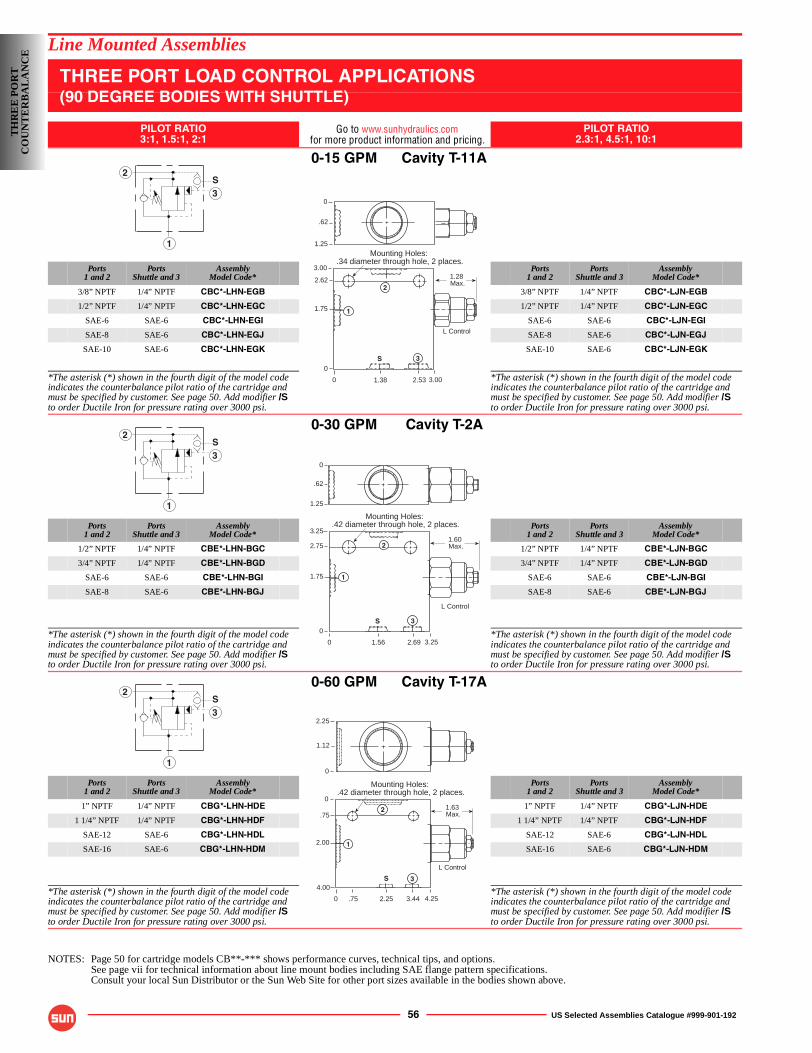
56 US Selected Assemblies Catalogue #999-901-192
Line Mounted Assemblies
THREE PORT LOAD CONTROL APPLICATIONS(90 DEGREE BODIES WITH SHUTTLE)
PILOT RATIO3:1, 1.5:1, 2:1
Go to www.sunhydraulics.comfor more product information and pricing.
PILOT RATIO2.3:1, 4.5:1, 10:1
0-15 GPM Cavity T-11A
Ports1 and 2
PortsShuttle and 3
AssemblyModel Code*
Ports1 and 2
PortsShuttle and 3
AssemblyModel Code*
3/8” NPTF 1/4” NPTF CBC*-LHN-EGB 3/8” NPTF 1/4” NPTF CBC*-LJN-EGB
1/2” NPTF 1/4” NPTF CBC*-LHN-EGC 1/2” NPTF 1/4” NPTF CBC*-LJN-EGC
SAE-6 SAE-6 CBC*-LHN-EGI SAE-6 SAE-6 CBC*-LJN-EGI
SAE-8 SAE-6 CBC*-LHN-EGJ SAE-8 SAE-6 CBC*-LJN-EGJ
SAE-10 SAE-6 CBC*-LHN-EGK SAE-10 SAE-6 CBC*-LJN-EGK
*The asterisk (*) shown in the fourth digit of the model code indicates the counterbalance pilot ratio of the cartridge and must be specified by customer. See page 50. Add modifier /Sto order Ductile Iron for pressure rating over 3000 psi.
*The asterisk (*) shown in the fourth digit of the model code indicates the counterbalance pilot ratio of the cartridge and must be specified by customer. See page 50. Add modifier /Sto order Ductile Iron for pressure rating over 3000 psi.
0-30 GPM Cavity T-2A
Ports1 and 2
PortsShuttle and 3
AssemblyModel Code*
Ports1 and 2
PortsShuttle and 3
AssemblyModel Code*
1/2” NPTF 1/4” NPTF CBE*-LHN-BGC 1/2” NPTF 1/4” NPTF CBE*-LJN-BGC
3/4” NPTF 1/4” NPTF CBE*-LHN-BGD 3/4” NPTF 1/4” NPTF CBE*-LJN-BGD
SAE-6 SAE-6 CBE*-LHN-BGI SAE-6 SAE-6 CBE*-LJN-BGI
SAE-8 SAE-6 CBE*-LHN-BGJ SAE-8 SAE-6 CBE*-LJN-BGJ
*The asterisk (*) shown in the fourth digit of the model code indicates the counterbalance pilot ratio of the cartridge and must be specified by customer. See page 50. Add modifier /Sto order Ductile Iron for pressure rating over 3000 psi.
*The asterisk (*) shown in the fourth digit of the model code indicates the counterbalance pilot ratio of the cartridge and must be specified by customer. See page 50. Add modifier /Sto order Ductile Iron for pressure rating over 3000 psi.
0-60 GPM Cavity T-17A
Ports1 and 2
PortsShuttle and 3
AssemblyModel Code*
Ports1 and 2
PortsShuttle and 3
AssemblyModel Code*
1” NPTF 1/4” NPTF CBG*-LHN-HDE 1” NPTF 1/4” NPTF CBG*-LJN-HDE
1 1/4” NPTF 1/4” NPTF CBG*-LHN-HDF 1 1/4” NPTF 1/4” NPTF CBG*-LJN-HDF
SAE-12 SAE-6 CBG*-LHN-HDL SAE-12 SAE-6 CBG*-LJN-HDL
SAE-16 SAE-6 CBG*-LHN-HDM SAE-16 SAE-6 CBG*-LJN-HDM
*The asterisk (*) shown in the fourth digit of the model code indicates the counterbalance pilot ratio of the cartridge and must be specified by customer. See page 50. Add modifier /Sto order Ductile Iron for pressure rating over 3000 psi.
*The asterisk (*) shown in the fourth digit of the model code indicates the counterbalance pilot ratio of the cartridge and must be specified by customer. See page 50. Add modifier /Sto order Ductile Iron for pressure rating over 3000 psi.
NOTES: Page 50 for cartridge models CB**-*** shows performance curves, technical tips, and options.See page vii for technical information about line mount bodies including SAE flange pattern specifications.Consult your local Sun Distributor or the Sun Web Site for other port sizes available in the bodies shown above.
S3
1
2
0
3.00
2.62
1.75
0
3.002.53
1.28 Max.
Mounting Holes:.34 diameter through hole, 2 places.
0
.62
1.25
L Control
1.38
1
2
3S
S3
1
2
0
3.25
2.75
1.75
0
3.252.69
1.60 Max.
Mounting Holes:.42 diameter through hole, 2 places.
0
.62
1.25
L Control
1.56
1
2
3S
S3
1
2
0
0
.75
2.00
4.00
4.253.44
1.63 Max.
Mounting Holes:.42 diameter through hole, 2 places.
2.25
1.12
0
L Control
2.25.75
1
2
3S
TH
RE
E P
OR
TC
OU
NT
ER
BA
LA
NC
E
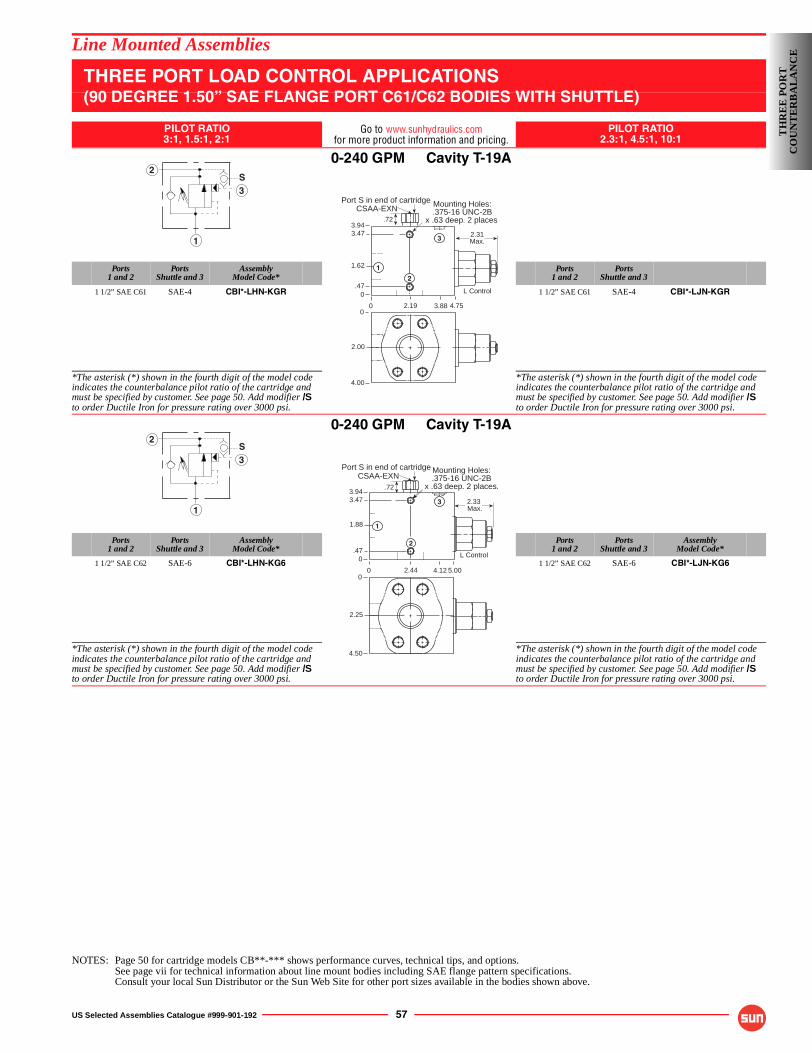
US Selected Assemblies Catalogue #999-901-192 57
3
1
2
Line Mounted Assemblies
THREE PORT LOAD CONTROL APPLICATIONS(90 DEGREE 1.50” SAE FLANGE PORT C61/C62 BODIES WITH SHUTTLE)
PILOT RATIO3:1, 1.5:1, 2:1
Go to www.sunhydraulics.comfor more product information and pricing.
PILOT RATIO2.3:1, 4.5:1, 10:1
0-240 GPM Cavity T-19A
Ports1 and 2
PortsShuttle and 3
AssemblyModel Code*
Ports1 and 2
PortsShuttle and 3
1 1/2” SAE C61 SAE-4 CBI*-LHN-KGR 1 1/2” SAE C61 SAE-4 CBI*-LJN-KGR
*The asterisk (*) shown in the fourth digit of the model code indicates the counterbalance pilot ratio of the cartridge and must be specified by customer. See page 50. Add modifier /Sto order Ductile Iron for pressure rating over 3000 psi.
*The asterisk (*) shown in the fourth digit of the model code indicates the counterbalance pilot ratio of the cartridge and must be specified by customer. See page 50. Add modifier /Sto order Ductile Iron for pressure rating over 3000 psi.
0-240 GPM Cavity T-19A
Ports1 and 2
PortsShuttle and 3
AssemblyModel Code*
Ports1 and 2
PortsShuttle and 3
AssemblyModel Code*
1 1/2” SAE C62 SAE-6 CBI*-LHN-KG6 1 1/2” SAE C62 SAE-6 CBI*-LJN-KG6
*The asterisk (*) shown in the fourth digit of the model code indicates the counterbalance pilot ratio of the cartridge and must be specified by customer. See page 50. Add modifier /Sto order Ductile Iron for pressure rating over 3000 psi.
*The asterisk (*) shown in the fourth digit of the model code indicates the counterbalance pilot ratio of the cartridge and must be specified by customer. See page 50. Add modifier /Sto order Ductile Iron for pressure rating over 3000 psi.
NOTES: Page 50 for cartridge models CB**-*** shows performance curves, technical tips, and options.See page vii for technical information about line mount bodies including SAE flange pattern specifications.Consult your local Sun Distributor or the Sun Web Site for other port sizes available in the bodies shown above.
S3
1
2
Port S in end of cartridge
0
3.943.47
1.62
0
4.753.882.19
2.31Max.
Mounting Holes:.375-16 UNC-2B
x .63 deep. 2 places.CSAA-EXN
.47L Control
.72
0
2.00
4.00
1
2
3
S3
1
2
.72
0
3.943.47
1.88
0
5.002.44
L Control
Mounting Holes:.375-16 UNC-2B
x .63 deep. 2 places.CSAA-EXN
2.33 Max.
4.12
.47
Port S in end of cartridge
0
2.25
4.50
1
3
2
TH
RE
E P
OR
TC
OU
NT
ER
BA
LA
NC
E
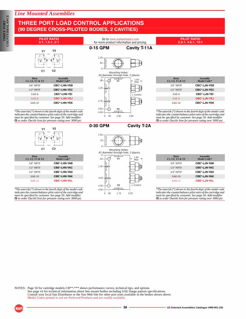
58 US Selected Assemblies Catalogue #999-901-192
Line Mounted Assemblies
THREE PORT LOAD CONTROL APPLICATIONS(90 DEGREE CROSS-PILOTED BODIES, 2 CAVITIES)
PILOT RATIO3:1, 1.5:1, 2:1
Go to www.sunhydraulics.comfor more product information and pricing.
PILOT RATIO2.3:1, 4.5:1, 10:1
0-15 GPM Cavity T-11A
PortsC1, C2, V1 & V2
AssemblyModel Code*
PortsC1, C2, V1 & V2
AssemblyModel Code*
3/8” NPTF CBC*-LHN-YEB 3/8” NPTF CBC*-LJN-YEB
1/2” NPTF CBC*-LHN-YEC 1/2” NPTF CBC*-LJN-YEC
SAE-6 CBC*-LHN-YEI SAE-6 CBC*-LJN-YEI
SAE-8 CBC*-LHN-YEJ SAE-8 CBC*-LJN-YEJ
SAE-10 CBC*-LHN-YEK SAE-10 CBC*-LJN-YEK
*The asterisk (*) shown in the fourth digit of the model code indicates the counterbalance pilot ratio of the cartridge and must be specified by customer. See page 50. Add modifier/S to order Ductile Iron for pressure rating over 3000 psi.
*The asterisk (*) shown in the fourth digit of the model code indicates the counterbalance pilot ratio of the cartridge and must be specified by customer. See page 50. Add modifier/S to order Ductile Iron for pressure rating over 3000 psi.
0-30 GPM Cavity T-2A
PortsC1, C2, V1 & V2
AssemblyModel Code*
PortsC1, C2, V1 & V2
AssemblyModel Code*
3/8” NPTF CBE*-LHN-YAB 3/8” NPTF CBE*-LJN-YAB
1/2” NPTF CBE*-LHN-YAC 1/2” NPTF CBE*-LJN-YAC
3/4” NPTF CBE*-LHN-YAD 3/4” NPTF CBE*-LJN-YAD
SAE-10 CBE*-LHN-YAK SAE-10 CBE*-LJN-YAK
SAE-12 CBE*-LHN-YAL SAE-12 CBE*-LJN-YAL
*The asterisk (*) shown in the fourth digit of the model code indicates the counterbalance pilot ratio of the cartridge and must be specified by customer. See page 50. Add modifier/S to order Ductile Iron for pressure rating over 3000 psi.
*The asterisk (*) shown in the fourth digit of the model code indicates the counterbalance pilot ratio of the cartridge and must be specified by customer. See page 50. Add modifier/S to order Ductile Iron for pressure rating over 3000 psi.
NOTES: Page 50 for cartridge models CB**-*** shows performance curves, technical tips, and options.See page vii for technical information about line mount bodies including SAE flange pattern specifications.Consult your local Sun Distributor or the Sun Web Site for other port sizes available in the bodies shown above.Model Codes printed in red are Preferred Products and are readily available.
V1 V2
C1 C2
0
0.38
2.75
4.00
3.001.56.50
1.63 Max.
Mounting Holes:.34 diameter through hole, 2 places.
1.25
.62
0
L Control
3.62
1.25 C1
C2
V1
V2
V1 V2
C1 C2
0
0
.50
3.00
4.50
3.251.75.50
1.60 Max.
Mounting Holes:.42 diameter through hole, 2 places.
1.50
.75
0
L Control4.00
1.50 C1
C2
V1
V2
TH
RE
E P
OR
TC
OU
NT
ER
BA
LA
NC
E
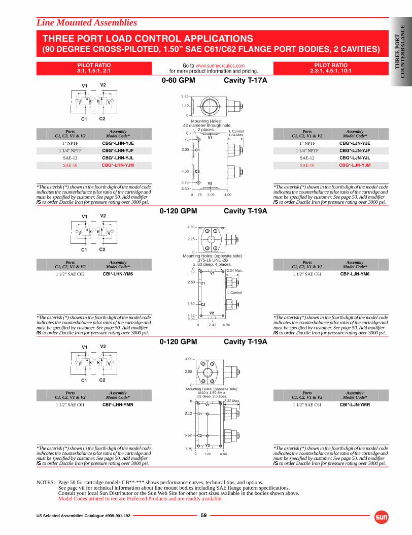
US Selected Assemblies Catalogue #999-901-192 59
Line Mounted Assemblies
THREE PORT LOAD CONTROL APPLICATIONS(90 DEGREE CROSS-PILOTED, 1.50” SAE C61/C62 FLANGE PORT BODIES, 2 CAVITIES)
PILOT RATIO3:1, 1.5:1, 2:1
Go to www.sunhydraulics.comfor more product information and pricing.
PILOT RATIO2.3:1, 4.5:1, 10:1
0-60 GPM Cavity T-17A
PortsC1, C2, V1 & V2
AssemblyModel Code*
PortsC1, C2, V1 & V2
AssemblyModel Code*
1” NPTF CBG*-LHN-YJE 1” NPTF CBG*-LJN-YJE
1 1/4” NPTF CBG*-LHN-YJF 1 1/4” NPTF CBG*-LJN-YJF
SAE-12 CBG*-LHN-YJL SAE-12 CBG*-LJN-YJL
SAE-16 CBG*-LHN-YJM SAE-16 CBG*-LJN-YJM
*The asterisk (*) shown in the fourth digit of the model code indicates the counterbalance pilot ratio of the cartridge and must be specified by customer. See page 50. Add modifier/S to order Ductile Iron for pressure rating over 3000 psi.
*The asterisk (*) shown in the fourth digit of the model code indicates the counterbalance pilot ratio of the cartridge and must be specified by customer. See page 50. Add modifier/S to order Ductile Iron for pressure rating over 3000 psi.
0-120 GPM Cavity T-19A
PortsC1, C2, V1 & V2
AssemblyModel Code*
PortsC1, C2, V1 & V2
AssemblyModel Code*
1 1/2” SAE C62 CBI*-LHN-YM6 1 1/2” SAE C61 CBI*-LJN-YM6
*The asterisk (*) shown in the fourth digit of the model code indicates the counterbalance pilot ratio of the cartridge and must be specified by customer. See page 50. Add modifier/S to order Ductile Iron for pressure rating over 3000 psi.
*The asterisk (*) shown in the fourth digit of the model code indicates the counterbalance pilot ratio of the cartridge and must be specified by customer. See page 50. Add modifier/S to order Ductile Iron for pressure rating over 3000 psi.
0-120 GPM Cavity T-19A
PortsC1, C2, V1 & V2
AssemblyModel Code*
PortsC1, C2, V1 & V2
AssemblyModel Code*
1 1/2” SAE C61 CBI*-LHN-YMR 1 1/2” SAE C61 CBI*-LJN-YMR
*The asterisk (*) shown in the fourth digit of the model code indicates the counterbalance pilot ratio of the cartridge and must be specified by customer. See page 50. Add modifier/S to order Ductile Iron for pressure rating over 3000 psi.
*The asterisk (*) shown in the fourth digit of the model code indicates the counterbalance pilot ratio of the cartridge and must be specified by customer. See page 50. Add modifier/S to order Ductile Iron for pressure rating over 3000 psi.
NOTES: Page 50 for cartridge models CB**-*** shows performance curves, technical tips, and options.See page vii for technical information about line mount bodies including SAE flange pattern specifications.Consult your local Sun Distributor or the Sun Web Site for other port sizes available in the bodies shown above.Model Codes printed in red are Preferred Products and are readily available.
V1 V2
C1 C2
L Control1.84 Max.
0
0
.75
4.50
6.50
4.002.09.75
Mounting Holes:.42 diameter through hole,
2 places.
2.25
1.12
0
5.75
2.00
C2
V1
V2
C1
V1 V2
C1 C2
C1
C2
V1
V2
2.34 Max.
0
0
6.50
9.03
4.942.41
Mounting Holes: (opposite side).375-16 UNC-2B
x .62 deep. 4 places.
4.50
2.25
0
2.53
L Control
.52
8.52
V1 V2
C1 C2
2.00
4.00
0Mounting Holes: (opposite side)
M10 x 1.50-6H x.62 deep. 2 places.
0
2.12
5.62
7.75
2.32 Max.
0 1.88 4.44
V1
C1
C2
V2
TH
RE
E P
OR
TC
OU
NT
ER
BA
LA
NC
E
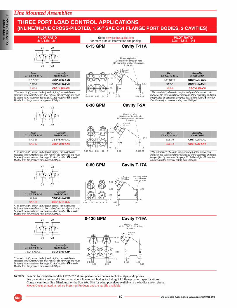
60 US Selected Assemblies Catalogue #999-901-192
Line Mounted Assemblies
THREE PORT LOAD CONTROL APPLICATIONS(INLINE/INLINE CROSS-PILOTED, 1.50” SAE C61 FLANGE PORT BODIES, 2 CAVITIES)
PILOT RATIO3:1, 1.5:1, 2:1
Go to www.sunhydraulics.comfor more product information and pricing.
PILOT RATIO2.3:1, 4.5:1, 10:1
0-15 GPM Cavity T-11A
PortsC1, C2, V1 & V2
AssemblyModel Code*
PortsC1, C2, V1 & V2
AssemblyModel Code*
3/8” NPTF CBC*-LHN-XVG 3/8” NPTF CBC*-LJN-XVG
SAE-6 CBC*-LHN-XVH SAE-6 CBC*-LJN-XVH
SAE-8 CBC*-LHN-XVI SAE-8 CBC*-LJN-XVI
*The asterisk (*) shown in the fourth digit of the model code indicates the counterbalance pilot ratio of the cartridge and must be specified by customer. See page 50. Add modifier /S to order Ductile Iron for pressure rating over 3000 psi.
*The asterisk (*) shown in the fourth digit of the model code indicates the counterbalance pilot ratio of the cartridge and must be specified by customer. See page 50. Add modifier /S to order Ductile Iron for pressure rating over 3000 psi.
0-30 GPM Cavity T-2A
PortsC1, C2, V1 & V2
AssemblyModel Code*
PortsC1, C2, V1 & V2
AssemblyModel Code*
SAE-10 CBE*-LHN-XAL SAE-10 CBE*-LJN-XAL
SAE-12 CBE*-LHN-XAK SAE-12 CBE*-LJN-XAK
*The asterisk (*) shown in the fourth digit of the model code indicates the counterbalance pilot ratio of the cartridge and must be specified by customer. See page 50. Add modifier /S to order Ductile Iron for pressure rating over 3000 psi.
*The asterisk (*) shown in the fourth digit of the model code indicates the counterbalance pilot ratio of the cartridge and must be specified by customer. See page 50. Add modifier /S to order Ductile Iron for pressure rating over 3000 psi.
0-60 GPM Cavity T-17A
PortsC1, C2, V1 & V2
AssemblyModel Code*
SAE-16 CBG*-LHN-XJMSAE-20 CBG*-LHN-XJL
*The asterisk (*) shown in the fourth digit of the model code indicates the counterbalance pilot ratio of the cartridge and must be specified by customer. See page 50. Add modifier /S to order Ductile Iron for pressure rating over 3000 psi.
0-120 GPM Cavity T-19A
PortsC1, C2, V1 & V2
AssemblyModel Code*
1 1/2” SAE C61 CBIA-LHN-XZP
*The asterisk (*) shown in the fourth digit of the model code indicates the counterbalance pilot ratio of the cartridge and must be specified by customer. See page 50. Add modifier /S to order Ductile Iron for pressure rating over 3000 psi.
NOTES: Page 50 for cartridge models CB**-*** shows performance curves, technical tips, and options.See page vii for technical information about line mount bodies including SAE flange pattern specifications.Consult your local Sun Distributor or the Sun Web Site for other port sizes available in the bodies shown above.Model Codes printed in red are Preferred Products and are readily available.
V1 V2
C1 C2
Mounting Holes:.34 diameter through hole
.88 diameter socket clearance.2 places.
0
2.05
1.28
.66
0
3.383.10.292.94
1.28
0
.62
2.64
0
0
1.472.31
V1 V2
L Control1.28 Max.
V2 C2
V1 V2
C1 C2
2.56
1.66
.88
0
3.883.593.62
1.66
0
.78
3.22
01.812.84
V1 V2
Mounting Holes:.34 diameter through hole
.88 diameter socket clearance.2 places.
0.28
0
L Control1.66 Max.
C2V2
V1 V2
C1 C2
L Control2.75 Max.
0
3.63
V2V1
1.132.374.75 0
3.88
2.31
.94
0
2.28
4.63 0.384.25
Mounting Holes:.42 diameterthrough hole.
C2V2
V1 V2
C1 C2
2.00
6.29
5.00
0
0 1.281.88 5.69
6.28
V2 V1
Mounting Holes:M10 x1.50-6 H x 22.4 deep.
4 places.
0 .50 4.505.00
L Control2.34 Max.
C2
TH
RE
E P
OR
TC
OU
NT
ER
BA
LA
NC
E
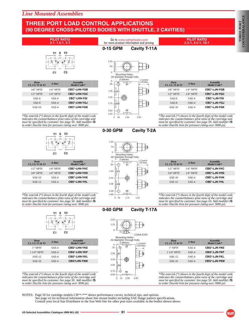
US Selected Assemblies Catalogue #999-901-192 61
Line Mounted Assemblies
THREE PORT LOAD CONTROL APPLICATIONS(90 DEGREE CROSS-PILOTED BODIES WITH SHUTTLE, 2 CAVITIES)
PILOT RATIO3:1, 1.5:1, 2:1
Go to www.sunhydraulics.comfor more product information and pricing.
PILOT RATIO2.3:1, 4.5:1, 10:1
0-15 GPM Cavity T-11A
PortsC1, C2, V1 & V2 S Port Assembly
Model Code*Ports
C1, C2, V1 & V2 S Port AssemblyModel Code*
3/8” NPTF 1/4” NPTF CBC*-LHN-YGB 3/8” NPTF 1/4” NPTF CBC*-LJN-YGB
1/2” NPTF 1/4” NPTF CBC*-LHN-YGC 1/2” NPTF 1/4” NPTF CBC*-LJN-YGC
SAE-6 SAE-4 CBC*-LHN-YGI SAE-6 SAE-4 CBC*-LJN-YGI
SAE-8 SAE-4 CBC*-LHN-YGJ SAE-8 SAE-4 CBC*-LJN-YGJ
SAE-10 SAE-4 CBC*-LHN-YGK SAE-10 SAE-4 CBC*-LJN-YGK
*The asterisk (*) shown in the fourth digit of the model code indicates the counterbalance pilot ratio of the cartridge and must be specified by customer. See page 50. Add modifier /Sto order Ductile Iron for pressure rating over 3000 psi.
*The asterisk (*) shown in the fourth digit of the model code indicates the counterbalance pilot ratio of the cartridge and must be specified by customer. See page 50. Add modifier /Sto order Ductile Iron for pressure rating over 3000 psi.
0-30 GPM Cavity T-2A
PortsC1, C2, V1 & V2 S Port Assembly
Model Code*Ports
C1, C2, V1 & V2 S Port AssemblyModel Code*
1/2” NPTF 1/4” NPTF CBE*-LHN-YHC 1/2” NPTF 1/4” NPTF CBE*-LJN-YHC
3/4” NPTF 1/4” NPTF CBE*-LHN-YHD 3/4” NPTF 1/4” NPTF CBE*-LJN-YHD
SAE-10 SAE-4 CBE*-LHN-YHK SAE-10 SAE-4 CBE*-LJN-YHK
SAE-12 SAE-4 CBE*-LHN-YHL SAE-12 SAE-4 CBE*-LJN-YHL
*The asterisk (*) shown in the fourth digit of the model code indicates the counterbalance pilot ratio of the cartridge and must be specified by customer. See page 50. Add modifier /Sto order Ductile Iron for pressure rating over 3000 psi.
*The asterisk (*) shown in the fourth digit of the model code indicates the counterbalance pilot ratio of the cartridge and must be specified by customer. See page 50. Add modifier /Sto order Ductile Iron for pressure rating over 3000 psi.
0-60 GPM Cavity T-17A
PortsC1, C2, V1 & V2 S Port Assembly
Model Code*Ports
C1, C2, V1 & V2 S Port AssemblyModel Code*
1” NPTF SAE-4 CBG*-LHN-YKE 1” NPTF SAE-4 CBG*-LJN-YKE
1 1/4” NPTF SAE-4 CBG*-LHN-YKF 1 1/4” NPTF SAE-4 CBG*-LJN-YKF
SAE-12 SAE-4 CBG*-LHN-YKL SAE-12 SAE-4 CBG*-LJN-YKL
SAE-16 SAE-4 CBG*LHN-YKM SAE-16 SAE-4 CBG*-LJN-YKM
*The asterisk (*) shown in the fourth digit of the model code indicates the counterbalance pilot ratio of the cartridge and must be specified by customer. See page 50. Add modifier /Sto order Ductile Iron for pressure rating over 3000 psi.
*The asterisk (*) shown in the fourth digit of the model code indicates the counterbalance pilot ratio of the cartridge and must be specified by customer. See page 50. Add modifier /Sto order Ductile Iron for pressure rating over 3000 psi.
NOTES: Page 50 for cartridge models CB**-*** shows performance curves, technical tips, and options.See page vii for technical information about line mount bodies including SAE flange pattern specifications.Consult your local Sun Distributor or the Sun Web Site for other port sizes available in the bodies shown above.
V1 V2
C1 C2
S
L Control1.28 Max.
0
0.38
2.75
4.00
3.001.56.50
Mounting Holes:.34 diameter through hole,
2 places.
1.25
.62
0
3.62
1.25
2.00
C1
C2
V1
V2
S
V1 V2
C1 C2
S
0
0
.50
3.38
4.88
3.251.75.50
L Control1.60 Max.
Mounting Holes:.42 diameter through hole,
2 places.
1.50
.75
0
4.38
1.50
2.44
C1
V1
S
C2
V2
V1 V2
C1 C2
S
L Control1.84 Max.
0
0.75
4.50
6.50
4.002.09.75
Mounting Holes:.42 diameter through hole,
2 places.
2.25
1.12
0
5.75
2.00
3.25
CSAA-EXN.72
S
V1
C1
C2
V2
TH
RE
E P
OR
TC
OU
NT
ER
BA
LA
NC
E
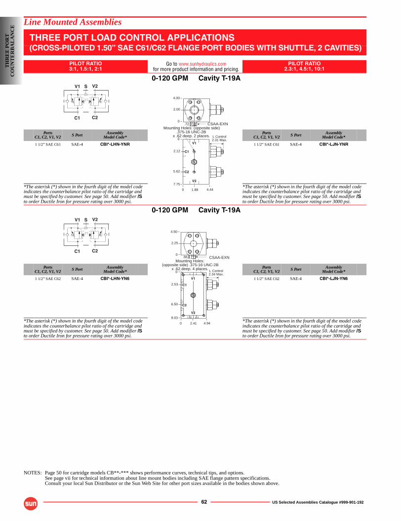
62 US Selected Assemblies Catalogue #999-901-192
Line Mounted Assemblies
THREE PORT LOAD CONTROL APPLICATIONS(CROSS-PILOTED 1.50” SAE C61/C62 FLANGE PORT BODIES WITH SHUTTLE, 2 CAVITIES)
PILOT RATIO3:1, 1.5:1, 2:1
Go to www.sunhydraulics.comfor more product information and pricing.
PILOT RATIO2.3:1, 4.5:1, 10:1
0-120 GPM Cavity T-19A
PortsC1, C2, V1, V2 S Port Assembly
Model Code*Ports
C1, C2, V1, V2 S Port AssemblyModel Code*
1 1/2” SAE C61 SAE-4 CBI*-LHN-YNR 1 1/2” SAE C61 SAE-4 CBI*-LJN-YNR
*The asterisk (*) shown in the fourth digit of the model code indicates the counterbalance pilot ratio of the cartridge and must be specified by customer. See page 50. Add modifier /Sto order Ductile Iron for pressure rating over 3000 psi.
*The asterisk (*) shown in the fourth digit of the model code indicates the counterbalance pilot ratio of the cartridge and must be specified by customer. See page 50. Add modifier /Sto order Ductile Iron for pressure rating over 3000 psi.
0-120 GPM Cavity T-19A
PortsC1, C2, V1, V2 S Port Assembly
Model Code*Ports
C1, C2, V1, V2 S Port AssemblyModel Code*
1 1/2” SAE C62 SAE-4 CBI*-LHN-YN6 1 1/2” SAE C62 SAE-4 CBI*-LJN-YN6
*The asterisk (*) shown in the fourth digit of the model code indicates the counterbalance pilot ratio of the cartridge and must be specified by customer. See page 50. Add modifier /Sto order Ductile Iron for pressure rating over 3000 psi.
*The asterisk (*) shown in the fourth digit of the model code indicates the counterbalance pilot ratio of the cartridge and must be specified by customer. See page 50. Add modifier /Sto order Ductile Iron for pressure rating over 3000 psi.
NOTES: Page 50 for cartridge models CB**-*** shows performance curves, technical tips, and options.See page vii for technical information about line mount bodies including SAE flange pattern specifications.Consult your local Sun Distributor or the Sun Web Site for other port sizes available in the bodies shown above.
V1 V2
C1 C2
S
L Control2.31 Max.
0
0
5.62
4.44
Mounting Holes: (opposite side).375-16 UNC-2B
x .62 deep. 2 places.
4.00
2.00
0
2.12
CSAA-EXN
1.88
7.75
.72
S
V1
C1
C2
V2
V1 V2
C1 C2
S
L Control2.34 Max.
0
0
6.50
9.03
4.942.41
Mounting Holes:(opposite side) .375-16 UNC-2B
x .62 deep. 4 places.
4.50
2.25
0
2.53
CSAA-EXN.66
S
V1
C1
C2
V2
TH
RE
E P
OR
TC
OU
NT
ER
BA
LA
NC
E
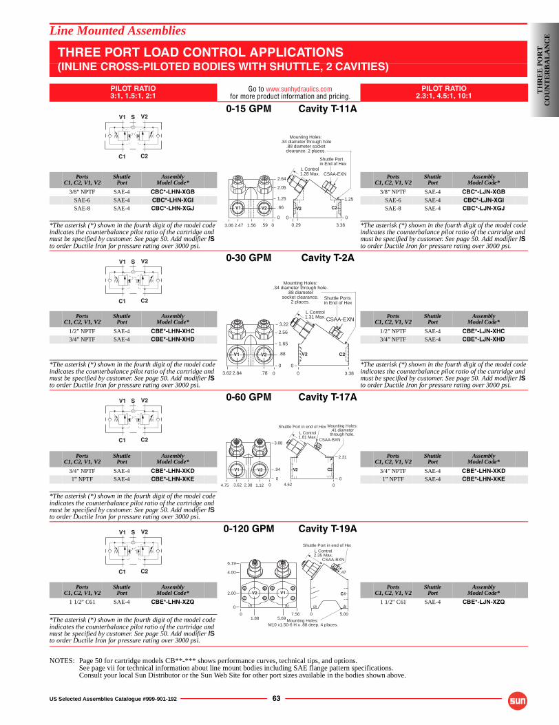
US Selected Assemblies Catalogue #999-901-192 63
Line Mounted Assemblies
THREE PORT LOAD CONTROL APPLICATIONS(INLINE CROSS-PILOTED BODIES WITH SHUTTLE, 2 CAVITIES)
PILOT RATIO3:1, 1.5:1, 2:1
Go to www.sunhydraulics.comfor more product information and pricing.
PILOT RATIO2.3:1, 4.5:1, 10:1
0-15 GPM Cavity T-11A
PortsC1, C2, V1, V2
ShuttlePort
AssemblyModel Code*
PortsC1, C2, V1, V2
ShuttlePort
AssemblyModel Code*
3/8” NPTF SAE-4 CBC*-LHN-XGB 3/8” NPTF SAE-4 CBC*-LJN-XGBSAE-6 SAE-4 CBC*-LHN-XGI SAE-6 SAE-4 CBC*-LJN-XGISAE-8 SAE-4 CBC*-LHN-XGJ SAE-8 SAE-4 CBC*-LJN-XGJ
*The asterisk (*) shown in the fourth digit of the model code indicates the counterbalance pilot ratio of the cartridge and must be specified by customer. See page 50. Add modifier /S to order Ductile Iron for pressure rating over 3000 psi.
*The asterisk (*) shown in the fourth digit of the model code indicates the counterbalance pilot ratio of the cartridge and must be specified by customer. See page 50. Add modifier /S to order Ductile Iron for pressure rating over 3000 psi.
0-30 GPM Cavity T-2A
PortsC1, C2, V1, V2
ShuttlePort
AssemblyModel Code*
PortsC1, C2, V1, V2
ShuttlePort
AssemblyModel Code*
1/2” NPTF SAE-4 CBE*-LHN-XHC 1/2” NPTF SAE-4 CBE*-LJN-XHC3/4” NPTF SAE-4 CBE*-LHN-XHD 3/4” NPTF SAE-4 CBE*-LJN-XHD
*The asterisk (*) shown in the fourth digit of the model code indicates the counterbalance pilot ratio of the cartridge and must be specified by customer. See page 50. Add modifier /S to order Ductile Iron for pressure rating over 3000 psi.
*The asterisk (*) shown in the fourth digit of the model code indicates the counterbalance pilot ratio of the cartridge and must be specified by customer. See page 50. Add modifier /S to order Ductile Iron for pressure rating over 3000 psi.
0-60 GPM Cavity T-17A
PortsC1, C2, V1, V2
ShuttlePort
AssemblyModel Code*
PortsC1, C2, V1, V2
ShuttlePort
AssemblyModel Code*
3/4” NPTF SAE-4 CBE*-LHN-XKD 3/4” NPTF SAE-4 CBE*-LHN-XKD1” NPTF SAE-4 CBE*-LHN-XKE 1” NPTF SAE-4 CBE*-LHN-XKE
*The asterisk (*) shown in the fourth digit of the model code indicates the counterbalance pilot ratio of the cartridge and must be specified by customer. See page 50. Add modifier /S to order Ductile Iron for pressure rating over 3000 psi.
0-120 GPM Cavity T-19A
PortsC1, C2, V1, V2
ShuttlePort
AssemblyModel Code*
PortsC1, C2, V1, V2
ShuttlePort
AssemblyModel Code*
1 1/2” C61 SAE-4 CBE*-LHN-XZQ 1 1/2” C61 SAE-4 CBE*-LJN-XZQ
*The asterisk (*) shown in the fourth digit of the model code indicates the counterbalance pilot ratio of the cartridge and must be specified by customer. See page 50. Add modifier /S to order Ductile Iron for pressure rating over 3000 psi.
NOTES: Page 50 for cartridge models CB**-*** shows performance curves, technical tips, and options.See page vii for technical information about line mount bodies including SAE flange pattern specifications.Consult your local Sun Distributor or the Sun Web Site for other port sizes available in the bodies shown above.
V1 V2
C1 C2
S
Mounting Holes:.34 diameter through hole
.88 diameter socketclearance. 2 places.
0
2.05
1.25
.66
0
3.38.29
1.25
0
.59
2.64
0
0
1.562.47
V1 V2
3.06
L Control1.28 Max.
Shuttle Portin End of Hex
CSAA-EXN
V2 C2
V1 V2
C1 C2
S
L Control1.31 Max.
Mounting Holes:.34 diameter through hole.
.88 diametersocket clearance.
2 places.
0
2.56
1.65
.88
0
3.62 .78
3.22
0
0
2.84
V1 V2
3.38
CSAA-EXN
Shuttle Portsin End of Hex
V2 C2
V1 V2
C1 C2
S
Shuttle Port in end of Hex
L Control1.81 Max.
CSAA-BXN
0
3.62
V2V1
1.122.384.75 0
3.88
.94
0
2.31
4.62 0
Mounting Holes:.41 diameterthrough hole.
C2V2
V1 V2
C1 C2
S
2.00
6.19
4.00
0
01.88 5.69
7.56
V2 V1
Mounting Holes:M10 x1.50-6 H x .88 deep. 4 places.
0 5.00
L Control2.35 Max.
.47
C1
Shuttle Port in end of Hex
CSAA-BXN
TH
RE
E P
OR
TC
OU
NT
ER
BA
LA
NC
E
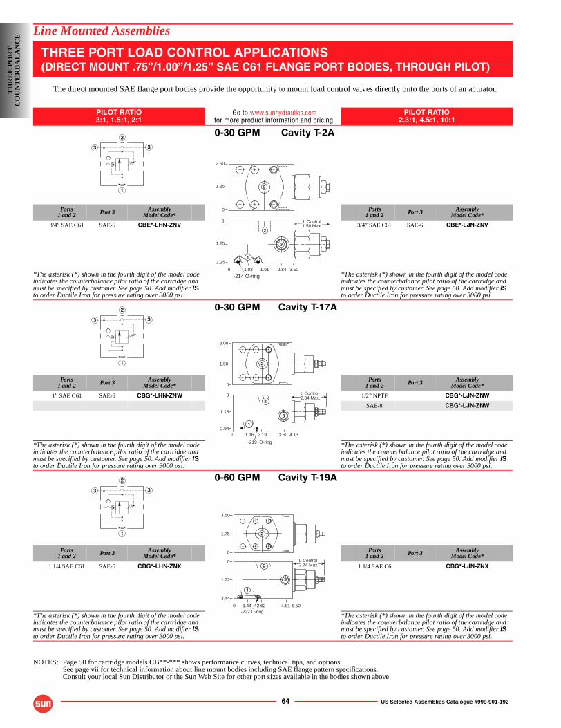
64 US Selected Assemblies Catalogue #999-901-192
Line Mounted Assemblies
THREE PORT LOAD CONTROL APPLICATIONS(DIRECT MOUNT .75”/1.00”/1.25” SAE C61 FLANGE PORT BODIES, THROUGH PILOT)
The direct mounted SAE flange port bodies provide the opportunity to mount load control valves directly onto the ports of an actuator.
PILOT RATIO3:1, 1.5:1, 2:1
Go to www.sunhydraulics.comfor more product information and pricing.
PILOT RATIO2.3:1, 4.5:1, 10:1
0-30 GPM Cavity T-2A
Ports1 and 2 Port 3 Assembly
Model Code*Ports
1 and 2 Port 3 AssemblyModel Code*
3/4” SAE C61 SAE-6 CBE*-LHN-ZNV 3/4” SAE C61 SAE-6 CBE*-LJN-ZNV
*The asterisk (*) shown in the fourth digit of the model code indicates the counterbalance pilot ratio of the cartridge and must be specified by customer. See page 50. Add modifier /Sto order Ductile Iron for pressure rating over 3000 psi.
*The asterisk (*) shown in the fourth digit of the model code indicates the counterbalance pilot ratio of the cartridge and must be specified by customer. See page 50. Add modifier /Sto order Ductile Iron for pressure rating over 3000 psi.
0-30 GPM Cavity T-17A
Ports1 and 2 Port 3 Assembly
Model Code*Ports
1 and 2 Port 3 AssemblyModel Code*
1” SAE C61 SAE-6 CBG*-LHN-ZNW 1/2” NPTF CBG*-LJN-ZNW
SAE-8 CBG*-LJN-ZNW
*The asterisk (*) shown in the fourth digit of the model code indicates the counterbalance pilot ratio of the cartridge and must be specified by customer. See page 50. Add modifier /Sto order Ductile Iron for pressure rating over 3000 psi.
*The asterisk (*) shown in the fourth digit of the model code indicates the counterbalance pilot ratio of the cartridge and must be specified by customer. See page 50. Add modifier /Sto order Ductile Iron for pressure rating over 3000 psi.
0-60 GPM Cavity T-19A
Ports1 and 2 Port 3 Assembly
Model Code*Ports
1 and 2 Port 3 AssemblyModel Code*
1 1/4 SAE C61 SAE-6 CBG*-LHN-ZNX 1 1/4 SAE C6 CBG*-LJN-ZNX
*The asterisk (*) shown in the fourth digit of the model code indicates the counterbalance pilot ratio of the cartridge and must be specified by customer. See page 50. Add modifier /Sto order Ductile Iron for pressure rating over 3000 psi.
*The asterisk (*) shown in the fourth digit of the model code indicates the counterbalance pilot ratio of the cartridge and must be specified by customer. See page 50. Add modifier /Sto order Ductile Iron for pressure rating over 3000 psi.
NOTES: Page 50 for cartridge models CB**-*** shows performance curves, technical tips, and options.See page vii for technical information about line mount bodies including SAE flange pattern specifications.Consult your local Sun Distributor or the Sun Web Site for other port sizes available in the bodies shown above.
3
2
3
1
0
0
1.25
2.25
3.502.84
L Control1.50 Max.
-214 O-ring
2.50
1.25
0
1.911.03
1
2
3
2
3
2
3
1
2.94
1.13
0
0 1.16 2.19 3.50 4.13
L Control2.34 Max.
-219 O-ring
3.00
1.50
0
3
2
1
2
3
2
3
1
3.50
1.75
0
0
1.72
3.44
0 1.44 2.62 4.81 5.50-222 O-ring
L Control2.74 Max.
1
2
3
2
TH
RE
E P
OR
TC
OU
NT
ER
BA
LA
NC
E
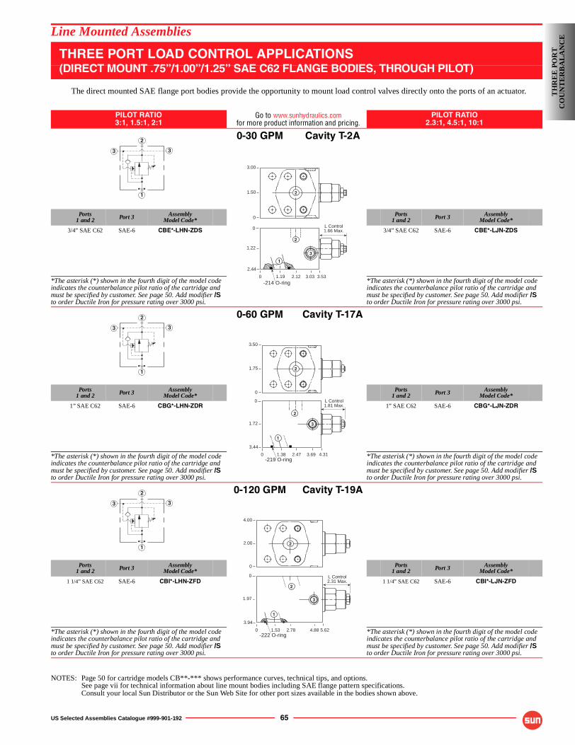
US Selected Assemblies Catalogue #999-901-192 65
Line Mounted Assemblies
THREE PORT LOAD CONTROL APPLICATIONS(DIRECT MOUNT .75”/1.00”/1.25” SAE C62 FLANGE BODIES, THROUGH PILOT)
The direct mounted SAE flange port bodies provide the opportunity to mount load control valves directly onto the ports of an actuator.
PILOT RATIO3:1, 1.5:1, 2:1
Go to www.sunhydraulics.comfor more product information and pricing.
PILOT RATIO2.3:1, 4.5:1, 10:1
0-30 GPM Cavity T-2A
Ports1 and 2 Port 3 Assembly
Model Code*Ports
1 and 2 Port 3 AssemblyModel Code*
3/4” SAE C62 SAE-6 CBE*-LHN-ZDS 3/4” SAE C62 SAE-6 CBE*-LJN-ZDS
*The asterisk (*) shown in the fourth digit of the model code indicates the counterbalance pilot ratio of the cartridge and must be specified by customer. See page 50. Add modifier /Sto order Ductile Iron for pressure rating over 3000 psi.
*The asterisk (*) shown in the fourth digit of the model code indicates the counterbalance pilot ratio of the cartridge and must be specified by customer. See page 50. Add modifier /Sto order Ductile Iron for pressure rating over 3000 psi.
0-60 GPM Cavity T-17A
Ports1 and 2 Port 3 Assembly
Model Code*Ports
1 and 2 Port 3 AssemblyModel Code*
1” SAE C62 SAE-6 CBG*-LHN-ZDR 1” SAE C62 SAE-6 CBG*-LJN-ZDR
*The asterisk (*) shown in the fourth digit of the model code indicates the counterbalance pilot ratio of the cartridge and must be specified by customer. See page 50. Add modifier /Sto order Ductile Iron for pressure rating over 3000 psi.
*The asterisk (*) shown in the fourth digit of the model code indicates the counterbalance pilot ratio of the cartridge and must be specified by customer. See page 50. Add modifier /Sto order Ductile Iron for pressure rating over 3000 psi.
0-120 GPM Cavity T-19A
Ports1 and 2 Port 3 Assembly
Model Code*Ports
1 and 2 Port 3 AssemblyModel Code*
1 1/4” SAE C62 SAE-6 CBI*-LHN-ZFD 1 1/4” SAE C62 SAE-6 CBI*-LJN-ZFD
*The asterisk (*) shown in the fourth digit of the model code indicates the counterbalance pilot ratio of the cartridge and must be specified by customer. See page 50. Add modifier /Sto order Ductile Iron for pressure rating over 3000 psi.
*The asterisk (*) shown in the fourth digit of the model code indicates the counterbalance pilot ratio of the cartridge and must be specified by customer. See page 50. Add modifier /Sto order Ductile Iron for pressure rating over 3000 psi.
NOTES: Page 50 for cartridge models CB**-*** shows performance curves, technical tips, and options.See page vii for technical information about line mount bodies including SAE flange pattern specifications.Consult your local Sun Distributor or the Sun Web Site for other port sizes available in the bodies shown above.
3
2
3
1
L Control1.66 Max.
0
0
1.22
2.44
3.533.03
3.00
1.50
0
2.121.19-214 O-ring
1
2
3
2
3
2
3
1
L Control1.81 Max.
0
0
1.72
3.44
4.313.69
3.50
1.75
0
2.471.38-219 O-ring
1
2
3
2
3
2
3
1
L Control2.31 Max.
0
0
1.97
3.94
5.624.88
4.00
2.00
0
2.781.53-222 O-ring
1
2
3
2
TH
RE
E P
OR
TC
OU
NT
ER
BA
LA
NC
E
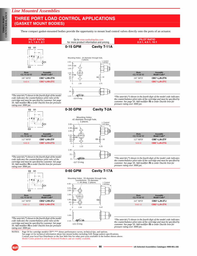
66 US Selected Assemblies Catalogue #999-901-192
Line Mounted Assemblies
THREE PORT LOAD CONTROL APPLICATIONS(GASKET MOUNT BODIES)
These compact gasket-mounted bodies provide the opportunity to mount load control valves directly onto the ports of an actuator.
PILOT RATIO3:1, 1.5:1, 2:1
Go to www.sunhydraulics.comfor more product information and pricing.
PILOT RATIO2.3:1, 4.5:1, 10:1
0-15 GPM Cavity T-11A
PortsC2, V1 & V2
AssemblyModel Code*
PortsC2, V1 & V2
AssemblyModel Code*
3/8” NPTF CBC*-LHN-ZTN 3/8” NPTF CBC*-LJN-ZTN
SAE-6 CBC*-LHN-ZTC SAE-6 CBC*-LJN-ZTC
*The asterisk (*) shown in the fourth digit of the model code indicates the counterbalance pilot ratio of the cartridge and must be specified by customer. See page 50. Add modifier /S to order Ductile Iron for pressure rating over 3000 psi.
*The asterisk (*) shown in the fourth digit of the model code indicates the counterbalance pilot ratio of the cartridge and must be specified by customer. See page 50. Add modifier /S to order Ductile Iron for pressure rating over 3000 psi.
0-30 GPM Cavity T-2A
PortsC2, V1 & V2
AssemblyModel Code*
PortsC2, V1 & V2
AssemblyModel Code*
1/2” NPTF CBE*-LHN-ZTF 1/2” NPTF CBE*-LJN-ZTF
SAE-8 CBE*-LHN-ZTG SAE-8 CBE*-LJN-ZTG
*The asterisk (*) shown in the fourth digit of the model code indicates the counterbalance pilot ratio of the cartridge and must be specified by customer. See page 50. Add modifier /S to order Ductile Iron for pressure rating over 3000 psi.
*The asterisk (*) shown in the fourth digit of the model code indicates the counterbalance pilot ratio of the cartridge and must be specified by customer. See page 50. Add modifier /S to order Ductile Iron for pressure rating over 3000 psi.
0-60 GPM Cavity T-17A
PortsC2, V1 & V2
AssemblyModel Code*
PortsC2, V1 & V2
AssemblyModel Code*
3/4” NPTF CBG*-LHN-ZTJ 3/4” NPTF CBG*-LJN-ZTJ
SAE-12 CBG*-LHN-ZTK SAE-12 CBG*-LJN-ZTK
*The asterisk (*) shown in the fourth digit of the model code indicates the counterbalance pilot ratio of the cartridge and must be specified by customer. See page 50. Add modifier /S to order Ductile Iron for pressure rating over 3000 psi.
*The asterisk (*) shown in the fourth digit of the model code indicates the counterbalance pilot ratio of the cartridge and must be specified by customer. See page 50. Add modifier /S to order Ductile Iron for pressure rating over 3000 psi.
NOTES: Page 50 for cartridge models CB**-*** shows performance curves, technical tips, and options.See page vii for technical information about line mount bodies including SAE flange pattern specifications.Consult your local Sun Distributor or the Sun Web Site for other port sizes available in the bodies shown above.Model Codes printed in red are Preferred Products and are readily available.
V2 V1
C1
C2
0
.59
1.19
-113 O-ring
L Control1.28 Max.
0
2.50
1.63
.81
0
3.75
Mounting Holes: .34 diameter through hole,2 places.
1.00
2.00
1.03
.31
.50V2
V1
C1
C2 .50
V2 V1
C1
C2
L Control1.63 Max.
0
3.00
.94
0
4.25
Mounting Holes:.42 diameter through hole,
2 places.
1.22
2.38
1.22
.34
1.94
.63
C1
V1
V2C2
1.44
-117 O-ring
.72
0
.63
V2 V1
C1
C2
0
1.09
2.19
-121 O-ring
L Control1.69 Max.
0
4.00
2.69
1.06
0
5.47
Mounting Holes: .53 diameter through hole,counterbore .78 diameter
x .44 deep. 2 places.
1.44
3.25
1.56
.44V2
V1
C1
C2
TH
RE
E P
OR
TC
OU
NT
ER
BA
LA
NC
E
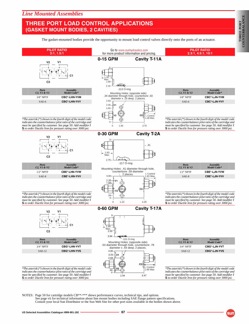
US Selected Assemblies Catalogue #999-901-192 67
Line Mounted Assemblies
THREE PORT LOAD CONTROL APPLICATIONS(GASKET MOUNT BODIES, 2 CAVITIES)
The gasket-mounted bodies provide the opportunity to mount load control valves directly onto the ports of an actuator.
PILOT RATIO3:1, 1.5:1
Go to www.sunhydraulics.comfor more product information and pricing.
PILOT RATIO2.3:1, 4.5:1, 10:1
0-15 GPM Cavity T-11A
PortsC2, V1 & V2
AssemblyModel Code*
PortsC2, V1 & V2
AssemblyModel Code*
3/8” NPTF CBC*-LHN-YVM 3/8” NPTF CBC*-LJN-YVM
SAE-6 CBC*-LHN-YVY SAE-6 CBC*-LJN-YVY
*The asterisk (*) shown in the fourth digit of the model code indicates the counterbalance pilot ratio of the cartridge and must be specified by customer. See page 50. Add modifier /S to order Ductile Iron for pressure rating over 3000 psi.
*The asterisk (*) shown in the fourth digit of the model code indicates the counterbalance pilot ratio of the cartridge and must be specified by customer. See page 50. Add modifier /S to order Ductile Iron for pressure rating over 3000 psi.
0-30 GPM Cavity T-2A
PortsC2, V1 & V2
AssemblyModel Code*
PortsC2, V1 & V2
AssemblyModel Code*
1/2” NPTF CBE*-LHN-YVW 1/2” NPTF CBE*-LJN-YVW
SAE-8 CBE*-LHN-YVV SAE-8 CBE*-LJN-YVV
*The asterisk (*) shown in the fourth digit of the model code indicates the counterbalance pilot ratio of the cartridge and must be specified by customer. See page 50. Add modifier /S to order Ductile Iron for pressure rating over 3000 psi.
*The asterisk (*) shown in the fourth digit of the model code indicates the counterbalance pilot ratio of the cartridge and must be specified by customer. See page 50. Add modifier /S to order Ductile Iron for pressure rating over 3000 psi.
0-60 GPM Cavity T-17A
PortsC2, V1 & V2
AssemblyModel Code*
PortsC2, V1 & V2
AssemblyModel Code*
3/4” NPTF CBG*-LHN-YVT 3/4” NPTF CBG*-LJN-YVT
SAE-12 CBG*-LHN-YVS SAE-12 CBG*-LJN-YVS
*The asterisk (*) shown in the fourth digit of the model code indicates the counterbalance pilot ratio of the cartridge and must be specified by customer. See page 50. Add modifier /S to order Ductile Iron for pressure rating over 3000 psi.
*The asterisk (*) shown in the fourth digit of the model code indicates the counterbalance pilot ratio of the cartridge and must be specified by customer. See page 50. Add modifier /S to order Ductile Iron for pressure rating over 3000 psi.
NOTES: Page 50 for cartridge models CB**-*** shows performance curves, technical tips, and options.See page vii for technical information about line mount bodies including SAE flange pattern specifications.Consult your local Sun Distributor or the Sun Web Site for other port sizes available in the bodies shown above.
V2 V1
C2
C11.28Max.
L Control1.28 Max.
0
2.50
0
3.75
Mounting Holes: (opposite side).34 diameter through hole, counterbore .50
diameter x .25 deep. 2 places.
0
2.19
1.00
2.00
-113 O-ring
1.62
C1
V1
V2
1.69
C2
V2 V1
C2
C1
L Control1.63 Max.
0
3.00
0
4.25
Mounting Holes: .41 diameter through hole,counterbore .59 diameter
2 places.
0
.81
2.75
1.22
2.38
C1
V1
V2C2
.34
-117 O-ring
1.94
1.63Max.
V2 V1
C2
C1 1.69Max.
C2C1
4.00
.440
1.44
Mounting Holes: (opposite side).53 diameter through hole, counterbore .78
diameter x .44 deep. 2 places.
-121 O-ring
0
L Control1.69 Max
2.50
3.94
3.252.69
5.47
V1
V2
TH
RE
E P
OR
TC
OU
NT
ER
BA
LA
NC
E
68 US Selected Assemblies Catalogue #999-901-192
Line Mounted Assemblies
NOTES
TH
RE
E P
OR
TC
OU
NT
ER
BA
LA
NC
E
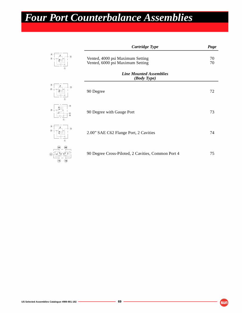
US Selected Assemblies Catalogue #999-901-192 69
Cartridge Type Page
Vented, 4000 psi Maximum SettingVented, 6000 psi Maximum Setting
7070
Line Mounted Assemblies(Body Type)
90 Degree 72
90 Degree with Gauge Port 73
2.00” SAE C62 Flange Port, 2 Cavities 74
90 Degree Cross-Piloted, 2 Cavities, Common Port 4 75
43
2
1
43
2
1
G
1
2
3
4
43
2
1
2A 2B
1B1A
4
Four Port Counterbalance Assemblies
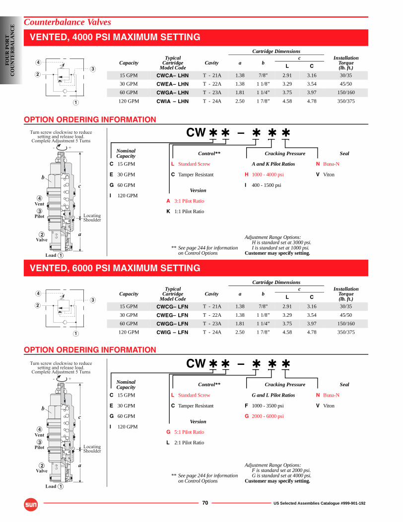
OPTION ORDERING INFORMATION
OPTION ORDERING INFORMATION
70 US Selected Assemblies Catalogue #999-901-192
Counterbalance Valves
VENTED, 4000 PSI MAXIMUM SETTING
CW ✱ ✱ – ✱ ✱ ✱
Nominal Control** Cracking Pressure SealCapacity
C 15 GPM L Standard Screw A and K Pilot Ratios N Buna-N
E 30 GPM C Tamper Resistant H 1000 - 4000 psi V Viton
G 60 GPM I 400 - 1500 psiVersion
I 120 GPMA 3:1 Pilot Ratio
K 1:1 Pilot Ratio
Adjustment Range Options:H is standard set at 3000 psi.
** See page 244 for information I is standard set at 1000 psi.on Control Options Customer may specify setting.
VENTED, 6000 PSI MAXIMUM SETTING
CW ✱ ✱ – ✱ ✱ ✱
Nominal Control** Cracking Pressure SealCapacity
C 15 GPM L Standard Screw G and L Pilot Ratios N Buna-N
E 30 GPM C Tamper Resistant F 1000 - 3500 psi V Viton
G 60 GPM G 2000 - 6000 psiVersion
I 120 GPMG 5:1 Pilot Ratio
L 2:1 Pilot Ratio
Adjustment Range Options:F is standard set at 2000 psi.
** See page 244 for information G is standard set at 4000 psi.on Control Options Customer may specify setting.
Cartridge Dimensions
CapacityTypical
CartridgeModel Code
Cavity a bc Installation
Torque(lb. ft.)L C
15 GPM CWCA– LHN T - 21A 1.38 7/8” 2.91 3.16 30/35
30 GPM CWEA– LHN T - 22A 1.38 1 1/8” 3.29 3.54 45/50
60 GPM CWGA– LHN T - 23A 1.81 1 1/4” 3.75 3.97 150/160
120 GPM CWIA – LHN T - 24A 2.50 1 7/8” 4.58 4.78 350/375
Cartridge Dimensions
CapacityTypical
CartridgeModel Code
Cavity a bc Installation
Torque(lb. ft.)L C
15 GPM CWCG– LFN T - 21A 1.38 7/8” 2.91 3.16 30/35
30 GPM CWEG– LFN T - 22A 1.38 1 1/8” 3.29 3.54 45/50
60 GPM CWGG– LFN T - 23A 1.81 1 1/4” 3.75 3.97 150/160
120 GPM CWIG – LFN T - 24A 2.50 1 7/8” 4.58 4.78 350/375
43
2
1
- +
Turn screw clockwise to reducesetting and release load.
Complete Adjustment 5 Turns
c
a
Load
Valve
Pilot
Vent
LocatingShoulder
b
4
3
2
1
43
2
1
- +
Turn screw clockwise to reducesetting and release load.
Complete Adjustment 5 Turns
c
a
Load
Valve
Pilot
Vent
LocatingShoulder
b
4
3
2
1
FOU
R P
OR
TC
OU
NT
ER
BA
LA
NC
E
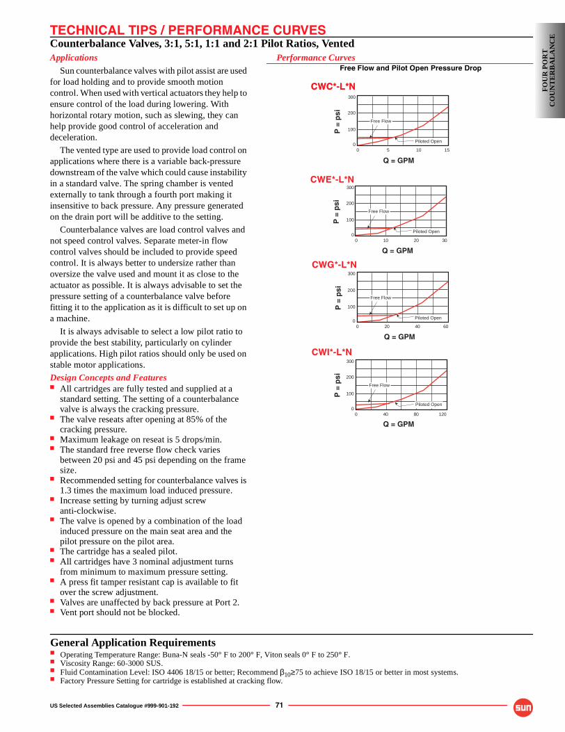
TECHNICAL TIPS / PERFORMANCE CURVES
US Selected Assemblies Catalogue #999-901-192 71
Counterbalance Valves, 3:1, 5:1, 1:1 and 2:1 Pilot Ratios, VentedApplications
Sun counterbalance valves with pilot assist are used for load holding and to provide smooth motion control. When used with vertical actuators they help to ensure control of the load during lowering. With horizontal rotary motion, such as slewing, they can help provide good control of acceleration and deceleration.
The vented type are used to provide load control on applications where there is a variable back-pressure downstream of the valve which could cause instability in a standard valve. The spring chamber is vented externally to tank through a fourth port making it insensitive to back pressure. Any pressure generated on the drain port will be additive to the setting.
Counterbalance valves are load control valves and not speed control valves. Separate meter-in flow control valves should be included to provide speed control. It is always better to undersize rather than oversize the valve used and mount it as close to the actuator as possible. It is always advisable to set the pressure setting of a counterbalance valve before fitting it to the application as it is difficult to set up on a machine.
It is always advisable to select a low pilot ratio to provide the best stability, particularly on cylinder applications. High pilot ratios should only be used on stable motor applications.
Design Concepts and Features■ All cartridges are fully tested and supplied at a
standard setting. The setting of a counterbalance valve is always the cracking pressure.
■ The valve reseats after opening at 85% of the cracking pressure.
■ Maximum leakage on reseat is 5 drops/min.■ The standard free reverse flow check varies
between 20 psi and 45 psi depending on the frame size.
■ Recommended setting for counterbalance valves is 1.3 times the maximum load induced pressure.
■ Increase setting by turning adjust screwanti-clockwise.
■ The valve is opened by a combination of the load induced pressure on the main seat area and the pilot pressure on the pilot area.
■ The cartridge has a sealed pilot.■ All cartridges have 3 nominal adjustment turns
from minimum to maximum pressure setting.■ A press fit tamper resistant cap is available to fit
over the screw adjustment.■ Valves are unaffected by back pressure at Port 2.■ Vent port should not be blocked.
Performance CurvesFree Flow and Pilot Open Pressure Drop
P =
psi
Q = GPM
200
300
100
200
03010
Piloted Open
Free Flow
CWE*-L*N
P =
psi
Q = GPM
400
300
100
200
06020
Piloted Open
Free Flow
CWG*-L*N
P =
psi
Q = GPM800
300
100
200
012040
Free Flow
Piloted Open
P =
psi
Q = GPM
100
300
100
200
0155
Free Flow
Piloted Open
CWC*-L*NCWC*-L*N
CWI*-L*N
FOU
R P
OR
TC
OU
NT
ER
BA
LA
NC
E
General Application Requirements■ Operating Temperature Range: Buna-N seals -50° F to 200° F, Viton seals 0° F to 250° F.■ Viscosity Range: 60-3000 SUS.■ Fluid Contamination Level: ISO 4406 18/15 or better; Recommend β10≥75 to achieve ISO 18/15 or better in most systems.■ Factory Pressure Setting for cartridge is established at cracking flow.
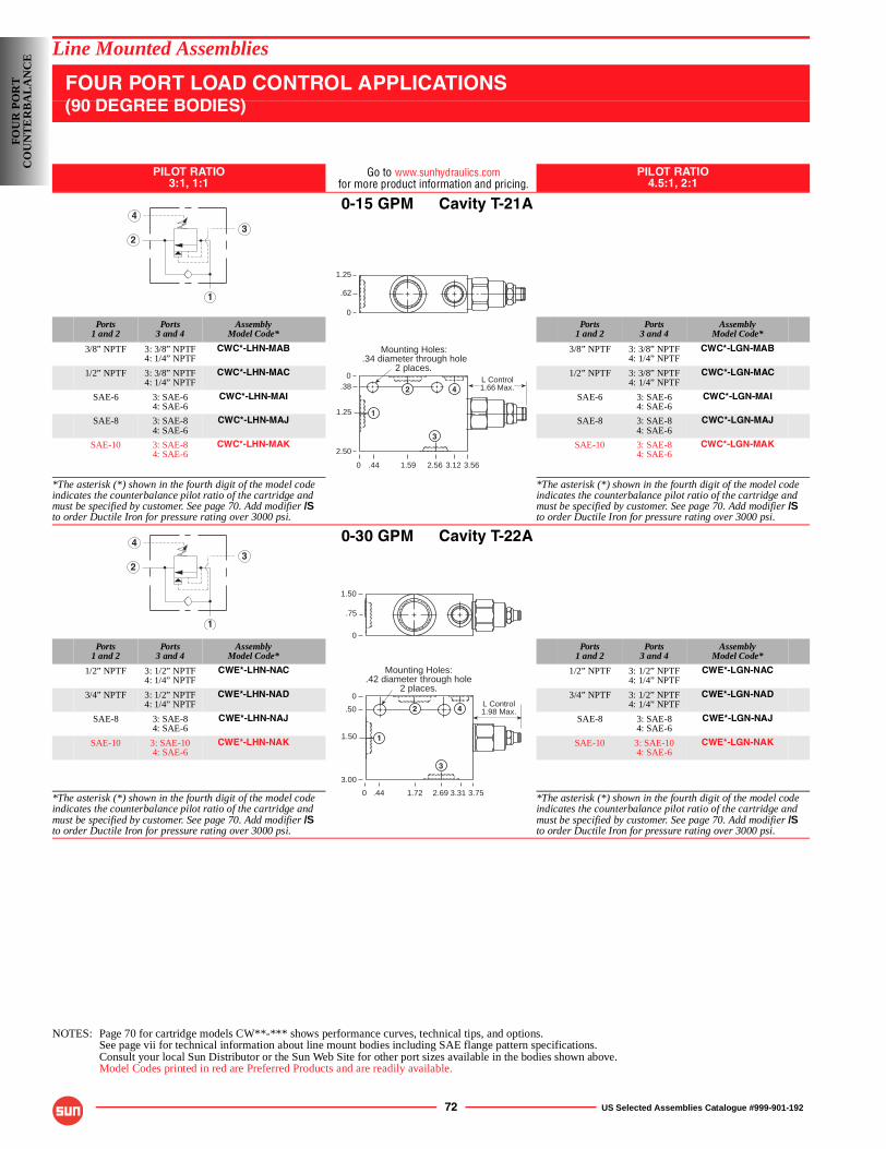
72 US Selected Assemblies Catalogue #999-901-192
Line Mounted Assemblies
FOUR PORT LOAD CONTROL APPLICATIONS(90 DEGREE BODIES)
PILOT RATIO3:1, 1:1
Go to www.sunhydraulics.comfor more product information and pricing.
PILOT RATIO4.5:1, 2:1
0-15 GPM Cavity T-21A
Ports1 and 2
Ports3 and 4
AssemblyModel Code*
Ports1 and 2
Ports3 and 4
AssemblyModel Code*
3/8” NPTF 3: 3/8” NPTF4: 1/4” NPTF
CWC*-LHN-MAB 3/8” NPTF 3: 3/8” NPTF4: 1/4” NPTF
CWC*-LGN-MAB
1/2” NPTF 3: 3/8” NPTF4: 1/4” NPTF
CWC*-LHN-MAC 1/2” NPTF 3: 3/8” NPTF4: 1/4” NPTF
CWC*-LGN-MAC
SAE-6 3: SAE-64: SAE-6
CWC*-LHN-MAI SAE-6 3: SAE-64: SAE-6
CWC*-LGN-MAI
SAE-8 3: SAE-84: SAE-6
CWC*-LHN-MAJ SAE-8 3: SAE-84: SAE-6
CWC*-LGN-MAJ
SAE-10 3: SAE-84: SAE-6
CWC*-LHN-MAK SAE-10 3: SAE-84: SAE-6
CWC*-LGN-MAK
*The asterisk (*) shown in the fourth digit of the model code indicates the counterbalance pilot ratio of the cartridge and must be specified by customer. See page 70. Add modifier /Sto order Ductile Iron for pressure rating over 3000 psi.
*The asterisk (*) shown in the fourth digit of the model code indicates the counterbalance pilot ratio of the cartridge and must be specified by customer. See page 70. Add modifier /Sto order Ductile Iron for pressure rating over 3000 psi.
0-30 GPM Cavity T-22A
Ports1 and 2
Ports3 and 4
AssemblyModel Code*
Ports1 and 2
Ports3 and 4
AssemblyModel Code*
1/2” NPTF 3: 1/2” NPTF4: 1/4” NPTF
CWE*-LHN-NAC 1/2” NPTF 3: 1/2” NPTF4: 1/4” NPTF
CWE*-LGN-NAC
3/4” NPTF 3: 1/2” NPTF4: 1/4” NPTF
CWE*-LHN-NAD 3/4” NPTF 3: 1/2” NPTF4: 1/4” NPTF
CWE*-LGN-NAD
SAE-8 3: SAE-84: SAE-6
CWE*-LHN-NAJ SAE-8 3: SAE-84: SAE-6
CWE*-LGN-NAJ
SAE-10 3: SAE-104: SAE-6
CWE*-LHN-NAK SAE-10 3: SAE-104: SAE-6
CWE*-LGN-NAK
*The asterisk (*) shown in the fourth digit of the model code indicates the counterbalance pilot ratio of the cartridge and must be specified by customer. See page 70. Add modifier /Sto order Ductile Iron for pressure rating over 3000 psi.
*The asterisk (*) shown in the fourth digit of the model code indicates the counterbalance pilot ratio of the cartridge and must be specified by customer. See page 70. Add modifier /Sto order Ductile Iron for pressure rating over 3000 psi.
NOTES: Page 70 for cartridge models CW**-*** shows performance curves, technical tips, and options.See page vii for technical information about line mount bodies including SAE flange pattern specifications.Consult your local Sun Distributor or the Sun Web Site for other port sizes available in the bodies shown above.Model Codes printed in red are Preferred Products and are readily available.
43
2
1
L Control1.66 Max.
1.25
.62
0
0
0.38
1.25
2.50
3.562.561.59
Mounting Holes:.34 diameter through hole
2 places.
1
2
3
4
.44 3.12
43
2
1
L Control1.98 Max.
Mounting Holes:.42 diameter through hole
2 places.
0
0
.50
1.50
3.00
3.752.691.72
1.50
.75
0
1
2
3
4
.44 3.31
FOU
R P
OR
TC
OU
NT
ER
BA
LA
NC
E
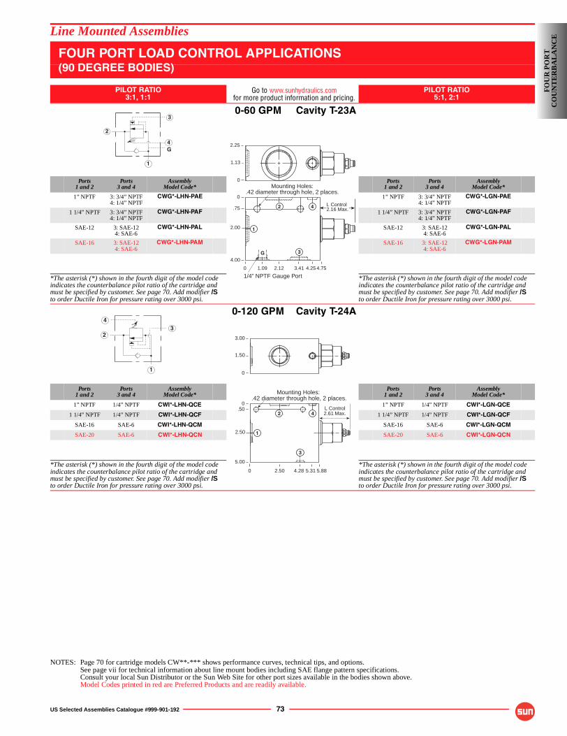
US Selected Assemblies Catalogue #999-901-192 73
Line Mounted Assemblies
FOUR PORT LOAD CONTROL APPLICATIONS(90 DEGREE BODIES)
PILOT RATIO3:1, 1:1
Go to www.sunhydraulics.comfor more product information and pricing.
PILOT RATIO5:1, 2:1
0-60 GPM Cavity T-23A
Ports1 and 2
Ports3 and 4
AssemblyModel Code*
Ports1 and 2
Ports3 and 4
AssemblyModel Code*
1” NPTF 3: 3/4” NPTF4: 1/4” NPTF
CWG*-LHN-PAE 1” NPTF 3: 3/4” NPTF4: 1/4” NPTF
CWG*-LGN-PAE
1 1/4” NPTF 3: 3/4” NPTF4: 1/4” NPTF
CWG*-LHN-PAF 1 1/4” NPTF 3: 3/4” NPTF4: 1/4” NPTF
CWG*-LGN-PAF
SAE-12 3: SAE-124: SAE-6
CWG*-LHN-PAL SAE-12 3: SAE-124: SAE-6
CWG*-LGN-PAL
SAE-16 3: SAE-124: SAE-6
CWG*-LHN-PAM SAE-16 3: SAE-124: SAE-6
CWG*-LGN-PAM
*The asterisk (*) shown in the fourth digit of the model code indicates the counterbalance pilot ratio of the cartridge and must be specified by customer. See page 70. Add modifier /Sto order Ductile Iron for pressure rating over 3000 psi.
*The asterisk (*) shown in the fourth digit of the model code indicates the counterbalance pilot ratio of the cartridge and must be specified by customer. See page 70. Add modifier /Sto order Ductile Iron for pressure rating over 3000 psi.
0-120 GPM Cavity T-24A
Ports1 and 2
Ports3 and 4
AssemblyModel Code*
Ports1 and 2
Ports3 and 4
AssemblyModel Code*
1” NPTF 1/4” NPTF CWI*-LHN-QCE 1” NPTF 1/4” NPTF CWI*-LGN-QCE
1 1/4” NPTF 1/4” NPTF CWI*-LHN-QCF 1 1/4” NPTF 1/4” NPTF CWI*-LGN-QCF
SAE-16 SAE-6 CWI*-LHN-QCM SAE-16 SAE-6 CWI*-LGN-QCM
SAE-20 SAE-6 CWI*-LHN-QCN SAE-20 SAE-6 CWI*-LGN-QCN
*The asterisk (*) shown in the fourth digit of the model code indicates the counterbalance pilot ratio of the cartridge and must be specified by customer. See page 70. Add modifier /Sto order Ductile Iron for pressure rating over 3000 psi.
*The asterisk (*) shown in the fourth digit of the model code indicates the counterbalance pilot ratio of the cartridge and must be specified by customer. See page 70. Add modifier /Sto order Ductile Iron for pressure rating over 3000 psi.
NOTES: Page 70 for cartridge models CW**-*** shows performance curves, technical tips, and options.See page vii for technical information about line mount bodies including SAE flange pattern specifications.Consult your local Sun Distributor or the Sun Web Site for other port sizes available in the bodies shown above.Model Codes printed in red are Preferred Products and are readily available.
G
1
2
3
4 2.25
1.13
0
0
0
.75
2.00
4.00
4.253.412.12
2.16 Max.
Mounting Holes:.42 diameter through hole, 2 places.
L Control
1.09 4.75
1
2
3
4
G
1/4” NPTF Gauge Port
43
2
1
0
0.50
2.50
5.00
5.884.282.50
L Control2.61 Max.
Mounting Holes:.42 diameter through hole, 2 places.
3.00
1.50
0
1
2
3
5.31
4
FOU
R P
OR
TC
OU
NT
ER
BA
LA
NC
E
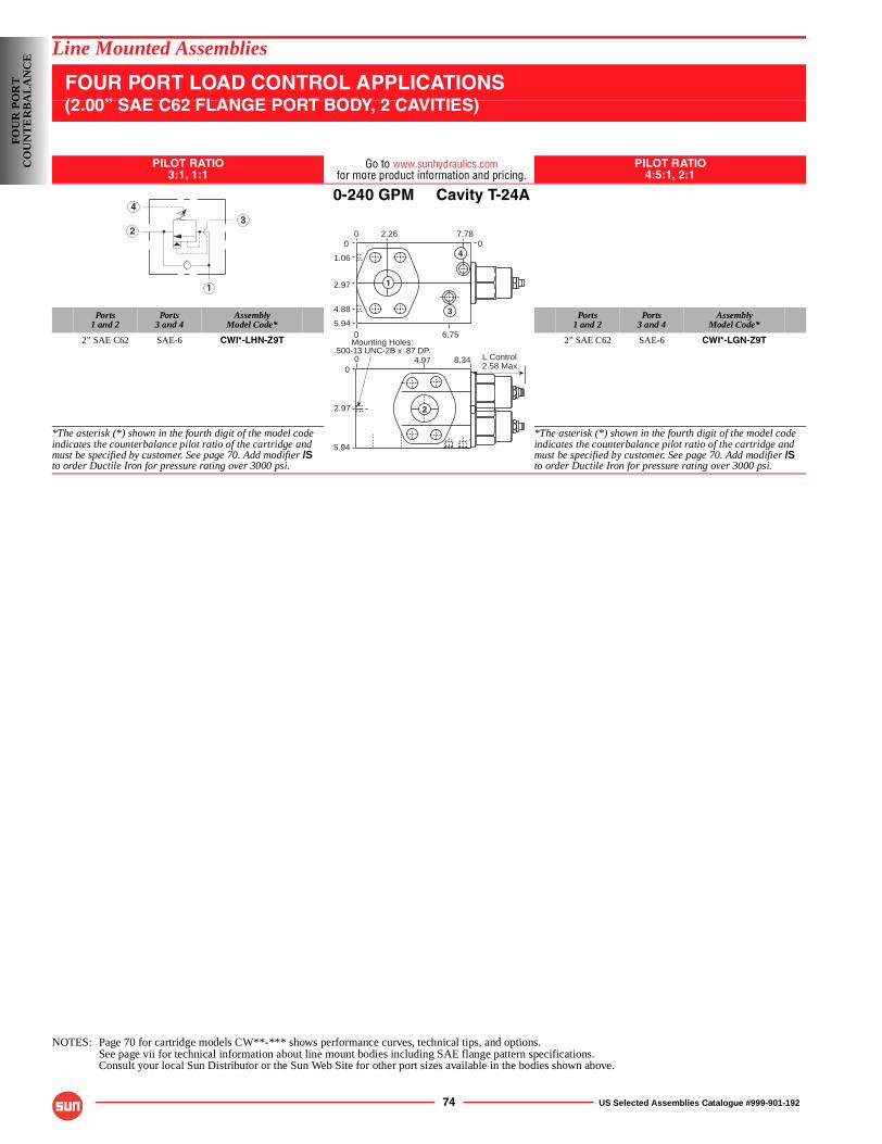
74 US Selected Assemblies Catalogue #999-901-192
Line Mounted Assemblies
FOUR PORT LOAD CONTROL APPLICATIONS(2.00” SAE C62 FLANGE PORT BODY, 2 CAVITIES)
PILOT RATIO3:1, 1:1
Go to www.sunhydraulics.comfor more product information and pricing.
PILOT RATIO4:5:1, 2:1
0-240 GPM Cavity T-24A
Ports1 and 2
Ports3 and 4
AssemblyModel Code*
Ports1 and 2
Ports3 and 4
AssemblyModel Code*
2” SAE C62 SAE-6 CWI*-LHN-Z9T 2” SAE C62 SAE-6 CWI*-LGN-Z9T
*The asterisk (*) shown in the fourth digit of the model code indicates the counterbalance pilot ratio of the cartridge and must be specified by customer. See page 70. Add modifier /Sto order Ductile Iron for pressure rating over 3000 psi.
*The asterisk (*) shown in the fourth digit of the model code indicates the counterbalance pilot ratio of the cartridge and must be specified by customer. See page 70. Add modifier /Sto order Ductile Iron for pressure rating over 3000 psi.
NOTES: Page 70 for cartridge models CW**-*** shows performance curves, technical tips, and options.See page vii for technical information about line mount bodies including SAE flange pattern specifications.Consult your local Sun Distributor or the Sun Web Site for other port sizes available in the bodies shown above.
43
2
1
2.58 Max.L Control
1
4
3
Mounting Holes:.500-13 UNC-2B x .87 DP.
2.260 7.7800
1.06
2.97
4.88
5.940 6.75
8.344.9700
2.97
5.94
2
FOU
R P
OR
TC
OU
NT
ER
BA
LA
NC
E
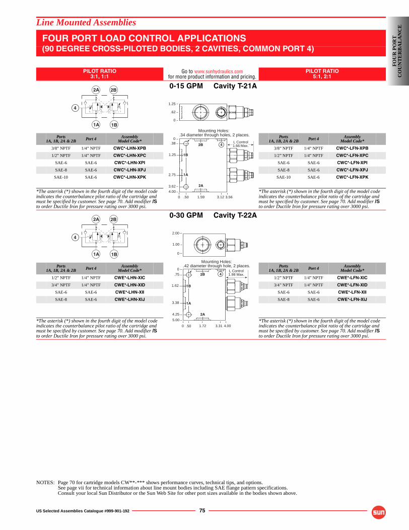
US Selected Assemblies Catalogue #999-901-192 75
Line Mounted Assemblies
FOUR PORT LOAD CONTROL APPLICATIONS(90 DEGREE CROSS-PILOTED BODIES, 2 CAVITIES, COMMON PORT 4)
PILOT RATIO3:1, 1:1
Go to www.sunhydraulics.comfor more product information and pricing.
PILOT RATIO5:1, 2:1
0-15 GPM Cavity T-21A
Ports1A, 1B, 2A & 2B Port 4 Assembly
Model Code*Ports
1A, 1B, 2A & 2B Port 4 AssemblyModel Code*
3/8” NPTF 1/4” NPTF CWC*-LHN-XPB 3/8” NPTF 1/4” NPTF CWC*-LFN-XPB
1/2” NPTF 1/4” NPTF CWC*-LHN-XPC 1/2” NPTF 1/4” NPTF CWC*-LFN-XPC
SAE-6 SAE-6 CWC*-LHN-XPI SAE-6 SAE-6 CWC*-LFN-XPI
SAE-8 SAE-6 CWC*-LHN-XPJ SAE-8 SAE-6 CWC*-LFN-XPJ
SAE-10 SAE-6 CWC*-LHN-XPK SAE-10 SAE-6 CWC*-LFN-XPK
*The asterisk (*) shown in the fourth digit of the model code indicates the counterbalance pilot ratio of the cartridge and must be specified by customer. See page 70. Add modifier /Sto order Ductile Iron for pressure rating over 3000 psi.
*The asterisk (*) shown in the fourth digit of the model code indicates the counterbalance pilot ratio of the cartridge and must be specified by customer. See page 70. Add modifier /Sto order Ductile Iron for pressure rating over 3000 psi.
0-30 GPM Cavity T-22A
Ports1A, 1B, 2A & 2B Port 4 Assembly
Model Code*Ports
1A, 1B, 2A & 2B Port 4 AssemblyModel Code*
1/2” NPTF 1/4” NPTF CWE*-LHN-XIC 1/2” NPTF 1/4” NPTF CWE*-LFN-XIC
3/4” NPTF 1/4” NPTF CWE*-LHN-XID 3/4” NPTF 1/4” NPTF CWE*-LFN-XID
SAE-6 SAE-6 CWE*-LHN-XII SAE-6 SAE-6 CWE*-LFN-XII
SAE-8 SAE-6 CWE*-LHN-XIJ SAE-8 SAE-6 CWE*-LFN-XIJ
*The asterisk (*) shown in the fourth digit of the model code indicates the counterbalance pilot ratio of the cartridge and must be specified by customer. See page 70. Add modifier /Sto order Ductile Iron for pressure rating over 3000 psi.
*The asterisk (*) shown in the fourth digit of the model code indicates the counterbalance pilot ratio of the cartridge and must be specified by customer. See page 70. Add modifier /Sto order Ductile Iron for pressure rating over 3000 psi.
NOTES: Page 70 for cartridge models CW**-*** shows performance curves, technical tips, and options.See page vii for technical information about line mount bodies including SAE flange pattern specifications.Consult your local Sun Distributor or the Sun Web Site for other port sizes available in the bodies shown above.
2A 2B
1B1A
41.25
.62
0
Mounting Holes:.34 diameter through holes, 2 places.
0
0.38
2.75
4.00
3.121.59
3.62
3.56
L Control1.66 Max.
1.25
.50
1B
1A
2B
2A
4
2A 2B
1B1A
4
0
0
.75
3.38
5.00
4.001.72.50
L Control1.98 Max.
Mounting Holes:.42 diameter through hole, 2 places.
1B
1A
2B
2.00
1.00
0
4.25
1.62
2A
4
3.31
FOU
R P
OR
TC
OU
NT
ER
BA
LA
NC
E
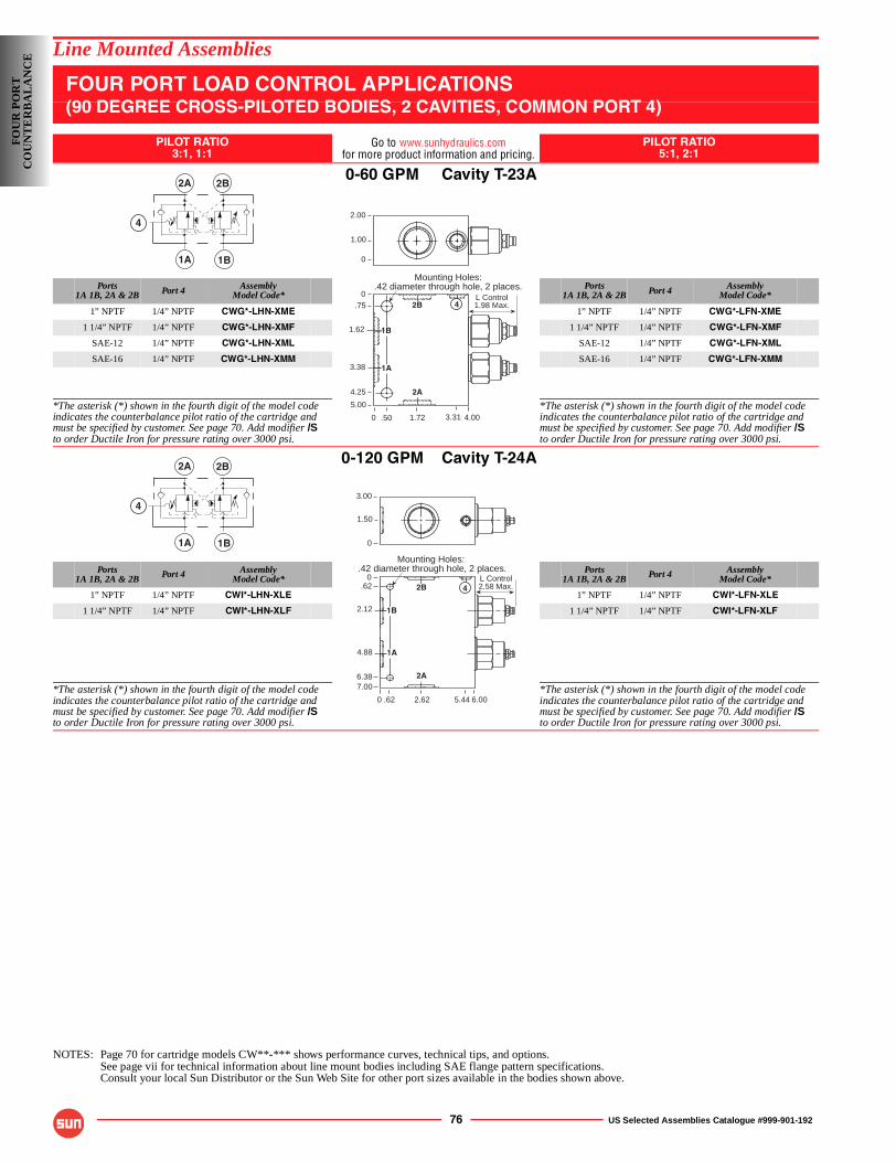
76 US Selected Assemblies Catalogue #999-901-192
Line Mounted Assemblies
FOUR PORT LOAD CONTROL APPLICATIONS(90 DEGREE CROSS-PILOTED BODIES, 2 CAVITIES, COMMON PORT 4)
PILOT RATIO3:1, 1:1
Go to www.sunhydraulics.comfor more product information and pricing.
PILOT RATIO5:1, 2:1
0-60 GPM Cavity T-23A
Ports1A 1B, 2A & 2B Port 4 Assembly
Model Code*Ports
1A 1B, 2A & 2B Port 4 AssemblyModel Code*
1” NPTF 1/4” NPTF CWG*-LHN-XME 1” NPTF 1/4” NPTF CWG*-LFN-XME
1 1/4” NPTF 1/4” NPTF CWG*-LHN-XMF 1 1/4” NPTF 1/4” NPTF CWG*-LFN-XMF
SAE-12 1/4” NPTF CWG*-LHN-XML SAE-12 1/4” NPTF CWG*-LFN-XML
SAE-16 1/4” NPTF CWG*-LHN-XMM SAE-16 1/4” NPTF CWG*-LFN-XMM
*The asterisk (*) shown in the fourth digit of the model code indicates the counterbalance pilot ratio of the cartridge and must be specified by customer. See page 70. Add modifier /Sto order Ductile Iron for pressure rating over 3000 psi.
*The asterisk (*) shown in the fourth digit of the model code indicates the counterbalance pilot ratio of the cartridge and must be specified by customer. See page 70. Add modifier /Sto order Ductile Iron for pressure rating over 3000 psi.
0-120 GPM Cavity T-24A
Ports1A 1B, 2A & 2B Port 4 Assembly
Model Code*Ports
1A 1B, 2A & 2B Port 4 AssemblyModel Code*
1” NPTF 1/4” NPTF CWI*-LHN-XLE 1” NPTF 1/4” NPTF CWI*-LFN-XLE
1 1/4” NPTF 1/4” NPTF CWI*-LHN-XLF 1 1/4” NPTF 1/4” NPTF CWI*-LFN-XLF
*The asterisk (*) shown in the fourth digit of the model code indicates the counterbalance pilot ratio of the cartridge and must be specified by customer. See page 70. Add modifier /Sto order Ductile Iron for pressure rating over 3000 psi.
*The asterisk (*) shown in the fourth digit of the model code indicates the counterbalance pilot ratio of the cartridge and must be specified by customer. See page 70. Add modifier /Sto order Ductile Iron for pressure rating over 3000 psi.
NOTES: Page 70 for cartridge models CW**-*** shows performance curves, technical tips, and options.See page vii for technical information about line mount bodies including SAE flange pattern specifications.Consult your local Sun Distributor or the Sun Web Site for other port sizes available in the bodies shown above.
2A 2B
1B1A
4
0
0
.75
3.38
5.00
4.001.72.50
L Control1.98 Max.
Mounting Holes:.42 diameter through hole, 2 places.
1B
1A
2B
2.00
1.00
0
4.25
1.62
2A
4
3.31
2A 2B
1B1A
4
L Control2.58 Max.
0
0.62
4.88
7.00
6.002.62.62
Mounting Holes:.42 diameter through hole, 2 places.
3.00
1.50
0
6.38
2.12
5.44
1B
1A
2B
2A
4
FO
UR
PO
RT
CO
UN
TE
RB
AL
AN
CE
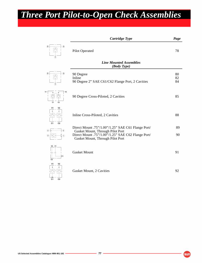
US Selected Assemblies Catalogue #999-901-192 77
Cartridge Type Page
Pilot Operated 78
Line Mounted Assemblies(Body Type)
90 DegreeInline90 Degree 2” SAE C61/C62 Flange Port, 2 Cavities
808284
90 Degree Cross-Piloted, 2 Cavities 85
Inline Cross-Piloted, 2 Cavities 88
Direct Mount .75”/1.00”/1.25” SAE C61 Flange Port/Gasket Mount, Through Pilot Port
Direct Mount .75”/1.00”/1.25” SAE C62 Flange Port/Gasket Mount, Through Pilot Port
89
90
Gasket Mount 91
Gasket Mount, 2 Cavities 92
1
2 3
1
2 3
C1 C2
V2V1
C1 C2
V1 V2
1
3
2
3
V2 V1
C1
C2
C1 C2
V1 V2
Three Port Pilot-to-Open Check Assemblies
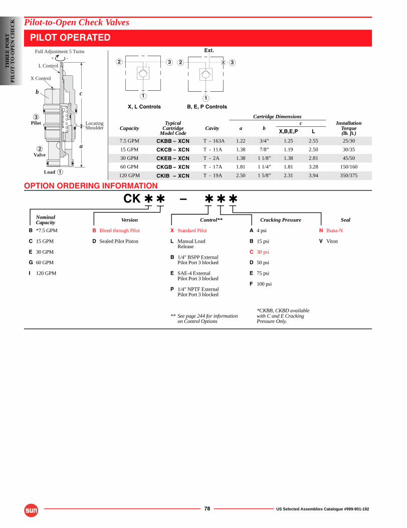
OPTION ORDERING INFORMATION
78 US Selected Assemblies Catalogue #999-901-192
Pilot-to-Open Check Valves
PILOT OPERATED
CK ✱ ✱ – ✱ ✱ ✱
Nominal Version Control** Cracking Pressure SealCapacity
B *7.5 GPM B Bleed through Pilot X Standard Pilot A 4 psi N Buna-N
C 15 GPM D Sealed Pilot Piston L Manual Load B 15 psi V VitonRelease
E 30 GPM C 30 psiB 1/4" BSPP External
G 60 GPM Pilot Port 3 blocked D 50 psi
I 120 GPM E SAE-4 External E 75 psiPilot Port 3 blocked
F 100 psiP 1/4" NPTF External
Pilot Port 3 blocked
*CKBB, CKBD available** See page 244 for information with C and E Cracking
on Control Options Pressure Only.
X, L Controls B, E, P Controls
Cartridge Dimensions
CapacityTypical
CartridgeModel Code
Cavity a bc Installation
Torque(lb. ft.)X,B,E,P L
7.5 GPM CKBB – XCN T - 163A 1.22 3/4” 1.25 2.55 25/30
15 GPM CKCB – XCN T - 11A 1.38 7/8” 1.19 2.50 30/35
30 GPM CKEB – XCN T - 2A 1.38 1 1/8” 1.38 2.81 45/50
60 GPM CKGB – XCN T - 17A 1.81 1 1/4” 1.81 3.28 150/160
120 GPM CKIB – XCN T - 19A 2.50 1 5/8” 2.31 3.94 350/375
LocatingShoulder
Load
3
2
1
c
a
L Control
X Control
Pilot
Valve
-+
Full Adjustment 5 Turns
b1
2 3
1
2 3
Ext.
TH
RE
E P
OR
TP
ILO
T-T
O-O
PE
N C
HE
CK
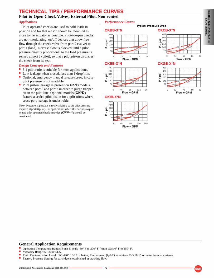
TECHNICAL TIPS / PERFORMANCE CURVES
US Selected Assemblies Catalogue #999-901-192 79
Pilot-to-Open Check Valves, External Pilot, Non-ventedApplications
Pilot operated checks are used to hold loads in position and for that reason should be mounted as close to the actuator as possible. Pilot-to-open checks are non-modulating, on/off devices that allow free flow through the check valve from port 2 (valve) to port 1 (load). Reverse flow is blocked until a pilot pressure directly proportional to the load pressure is sensed at port 3 (pilot), so that a pilot piston displaces the check from its seat.
Design Concepts and Features■ 3:1 pilot ratio is suitable for most applications.■ Low leakage when closed, less than 1 drop/min.■ Optional, emergency manual release screw, in case
pilot pressure is not available.■ Pilot piston leakage is present on CK*B models
between port 3 and port 2 in order to purge trapped air in the pilot line. Optional models (CK*D) feature a sealed pilot piston for applications where cross-port leakage is undesirable.
Note: Pressure at port 2 is directly additive to the pilot pressure required at port 3 (pilot). For applications where this occurs, a 4 port vented pilot operated check cartridge (CV*V-***) should be considered.
Performance CurvesTypical Pressure Drop
CKBB-X*N CKCB-X*N
CKEB-X*N CKGB-X*N
CKIB-X*N480
400
300
0 16040 80 120
Flow = GPM
P =
psi
210
140 70 XCN
XEN
FULL PILOT
480
400
300
0 205 10 15
Flow = GPM
P =
psi
210
140
70
XEN
XCNFULL PILOT
480
400
300
0 8020 40 60
210
Flow = GPM
P =
psi
140
70 XCN
XENFULL PILOT
480
400
300
0 102.5 5Flow = GPM
P =
psi
210
140
70
7.5
XEN
XCN FULL PILOT
480
400
300
0 307.5 15 22.5Flow = GPM
P =
psi
210
140
70 FULL PILOTXEN
XCN
TH
RE
E P
OR
TP
ILO
T-T
O-O
PE
N C
HE
CK
General Application Requirements■ Operating Temperature Range: Buna-N seals -50° F to 200° F, Viton seals 0° F to 250° F.■ Viscosity Range: 60-3000 SUS.■ Fluid Contamination Level: ISO 4406 18/15 or better; Recommend β10≥75 to achieve ISO 18/15 or better in most systems.■ Factory Pressure Setting for cartridge is established at cracking flow.
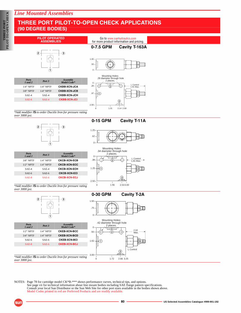
80 US Selected Assemblies Catalogue #999-901-192
Line Mounted Assemblies
THREE PORT PILOT-TO-OPEN CHECK APPLICATIONS(90 DEGREE BODIES)
PILOT OPERATEDASSEMBLIES
Go to www.sunhydraulics.comfor more product information and pricing.
0-7.5 GPM Cavity T-163A
Ports1 and 2 Port 3 Assembly
Model Code*
1/4” NPTF 1/4” NPTF CKBB-XCN-JCA
3/8” NPTF 1/4” NPTF CKBB-XCN-JCB
SAE-4 SAE-4 CKBB-XCN-JCH
SAE-6 SAE-4 CKBB-XCN-JCI
*Add modifier /S to order Ductile Iron for pressure rating over 3000 psi.
0-15 GPM Cavity T-11A
Ports1 and 2 Port 3 Assembly
Model Code*
3/8” NPTF 1/4” NPTF CKCB-XCN-ECB
1/2” NPTF 1/4” NPTF CKCB-XCN-ECC
SAE-4 SAE-4 CKCB-XCN-ECH
SAE-6 SAE-6 CKCB-XCN-ECI
SAE-8 SAE-6 CKCB-XCN-ECJ
*Add modifier /S to order Ductile Iron for pressure rating over 3000 psi.
0-30 GPM Cavity T-2A
Ports1 and 2 Port 3 Assembly
Model Code*
1/2” NPTF 1/4” NPTF CKEB-XCN-BCC
3/4” NPTF 1/4” NPTF CKEB-XCN-BCD
SAE-6 SAE-6 CKEB-XCN-BCI
SAE-8 SAE-6 CKEB-XCN-BCJ
*Add modifier /S to order Ductile Iron for pressure rating over 3000 psi.
NOTES: Page 78 for cartridge model CK*B-*** shows performance curves, technical tips, and options.See page vii for technical information about line mount bodies including SAE flange pattern specifications.Consult your local Sun Distributor or the Sun Web Site for other port sizes available in the bodies shown above.Model Codes printed in red are Preferred Products and are readily available.
1
2 3
L Control1.91 Max.
Mounting Holes:.28 diameter through hole
2 places.
0
0.28
.97
2.00
2.592.141.31
1.00
.50
0
1
3
2
1
2 3
L Control1.81 Max.
1.25
.62
0
0
0
.38
1.25
2.50
3.002.531.56
Mounting Holes:.34 diameter through hole
2 places.
1
2
3
1
2 3
2.02 Max.
Mounting Holes:.42 diameter through hole
2 places.
0
0
.50
1.62
3.00
3.252.661.72
1.50
.75
0
1
2
3L Control
TH
RE
E P
OR
TP
ILO
T-T
O-O
PE
N C
HE
CK
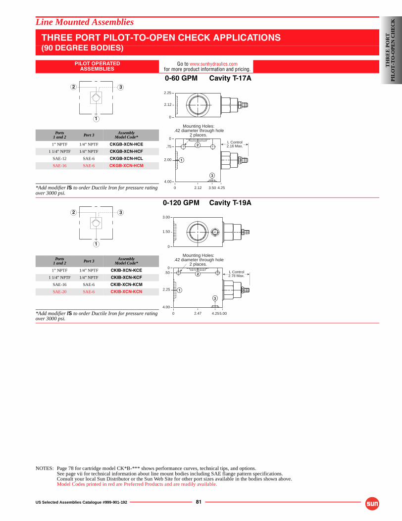
US Selected Assemblies Catalogue #999-901-192 81
Line Mounted Assemblies
THREE PORT PILOT-TO-OPEN CHECK APPLICATIONS(90 DEGREE BODIES)
PILOT OPERATEDASSEMBLIES
Go to www.sunhydraulics.comfor more product information and pricing.
0-60 GPM Cavity T-17A
Ports1 and 2 Port 3 Assembly
Model Code*
1” NPTF 1/4” NPTF CKGB-XCN-HCE
1 1/4” NPTF 1/4” NPTF CKGB-XCN-HCF
SAE-12 SAE-6 CKGB-XCN-HCL
SAE-16 SAE-6 CKGB-XCN-HCM
*Add modifier /S to order Ductile Iron for pressure rating over 3000 psi.
0-120 GPM Cavity T-19A
Ports1 and 2 Port 3 Assembly
Model Code*
1” NPTF 1/4” NPTF CKIB-XCN-KCE
1 1/4” NPTF 1/4” NPTF CKIB-XCN-KCF
SAE-16 SAE-6 CKIB-XCN-KCM
SAE-20 SAE-6 CKIB-XCN-KCN
*Add modifier /S to order Ductile Iron for pressure rating over 3000 psi.
NOTES: Page 78 for cartridge model CK*B-*** shows performance curves, technical tips, and options.See page vii for technical information about line mount bodies including SAE flange pattern specifications.Consult your local Sun Distributor or the Sun Web Site for other port sizes available in the bodies shown above.Model Codes printed in red are Preferred Products and are readily available.
1
2 3
0
0
.75
2.00
4.00
4.253.502.12
L Control2.16 Max.
Mounting Holes:.42 diameter through hole
2 places.
1
2
3
2.25
2.12
0
1
2 3
0
0.50
2.25
4.00
5.004.252.47
L Control2.78 Max.
Mounting Holes:.42 diameter through hole
2 places.
1
2
3
3.00
1.50
0
TH
RE
E P
OR
TP
ILO
T-T
O-O
PE
N C
HE
CK
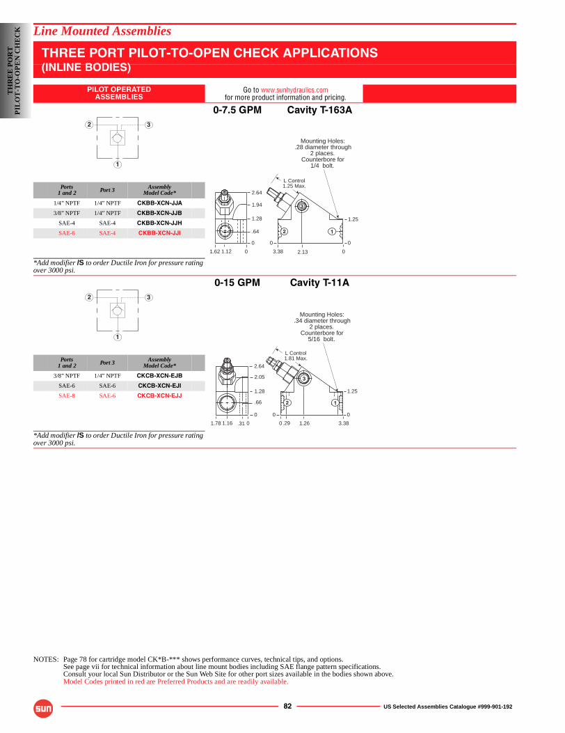
82 US Selected Assemblies Catalogue #999-901-192
Line Mounted Assemblies
THREE PORT PILOT-TO-OPEN CHECK APPLICATIONS(INLINE BODIES)
PILOT OPERATEDASSEMBLIES
Go to www.sunhydraulics.comfor more product information and pricing.
0-7.5 GPM Cavity T-163A
Ports1 and 2 Port 3 Assembly
Model Code*
1/4” NPTF 1/4” NPTF CKBB-XCN-JJA
3/8” NPTF 1/4” NPTF CKBB-XCN-JJB
SAE-4 SAE-4 CKBB-XCN-JJH
SAE-6 SAE-4 CKBB-XCN-JJI
*Add modifier /S to order Ductile Iron for pressure rating over 3000 psi.
0-15 GPM Cavity T-11A
Ports1 and 2 Port 3 Assembly
Model Code*
3/8” NPTF 1/4” NPTF CKCB-XCN-EJB
SAE-6 SAE-6 CKCB-XCN-EJI
SAE-8 SAE-6 CKCB-XCN-EJJ
*Add modifier /S to order Ductile Iron for pressure rating over 3000 psi.
NOTES: Page 78 for cartridge model CK*B-*** shows performance curves, technical tips, and options.See page vii for technical information about line mount bodies including SAE flange pattern specifications.Consult your local Sun Distributor or the Sun Web Site for other port sizes available in the bodies shown above.Model Codes printed in red are Preferred Products and are readily available.
1
2 3
Mounting Holes:.28 diameter through
2 places.Counterbore for
1/4 bolt.
3.38
1.94
1.28
.64
0
02.131.62
1.25
0
1.12
2.64
0
0
L Control1.25 Max.
3
2 1
1
2 3
Mounting Holes:.34 diameter through
2 places.Counterbore for
5/16 bolt.
0
2.05
1.28
.66
0
3.381.26.291.78
1.25
0
.311.16
2.64
0
0
L Control1.81 Max.
12
3
TH
RE
E P
OR
TP
ILO
T-T
O-O
PE
N C
HE
CK
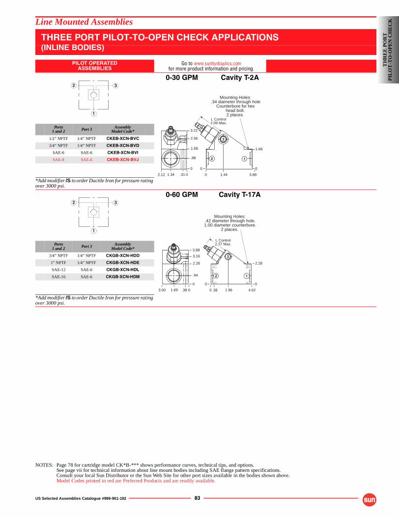
US Selected Assemblies Catalogue #999-901-192 83
Line Mounted Assemblies
THREE PORT PILOT-TO-OPEN CHECK APPLICATIONS(INLINE BODIES)
PILOT OPERATEDASSEMBLIES
Go to www.sunhydraulics.comfor more product information and pricing.
0-30 GPM Cavity T-2A
Ports1 and 2 Port 3 Assembly
Model Code*
1/2” NPTF 1/4” NPTF CKEB-XCN-BVC
3/4” NPTF 1/4” NPTF CKEB-XCN-BVD
SAE-6 SAE-6 CKEB-XCN-BVI
SAE-8 SAE-6 CKEB-XCN-BVJ
*Add modifier /S to order Ductile Iron for pressure rating over 3000 psi.
0-60 GPM Cavity T-17A
Ports1 and 2 Port 3 Assembly
Model Code*
3/4” NPTF 1/4” NPTF CKGB-XCN-HDD
1” NPTF 1/4” NPTF CKGB-XCN-HDE
SAE-12 SAE-6 CKGB-XCN-HDL
SAE-16 SAE-6 CKGB-XCN-HDM
*Add modifier /S to order Ductile Iron for pressure rating over 3000 psi.
NOTES: Page 78 for cartridge model CK*B-*** shows performance curves, technical tips, and options.See page vii for technical information about line mount bodies including SAE flange pattern specifications.Consult your local Sun Distributor or the Sun Web Site for other port sizes available in the bodies shown above.Model Codes printed in red are Preferred Products and are readily available.
1
2 3
Mounting Holes:.34 diameter through hole
Counterbore for hexhead bolt.2 places.
0 3.881.44
1.66
00
L Control2.09 Max.
12
32.56
1.68
.88
0
2.12 1.34
3.22
.31 0
1
2 3
L Control2.37 Max.
Mounting Holes:.42 diameter through hole.1.00 diameter counterbore.
2 places.
0
3.16
2.28
.94
0
4.621.96.383.00
2.28
0
.381.69
3.88
0
0
12
3
TH
RE
E P
OR
TP
ILO
T-T
O-O
PE
N C
HE
CK
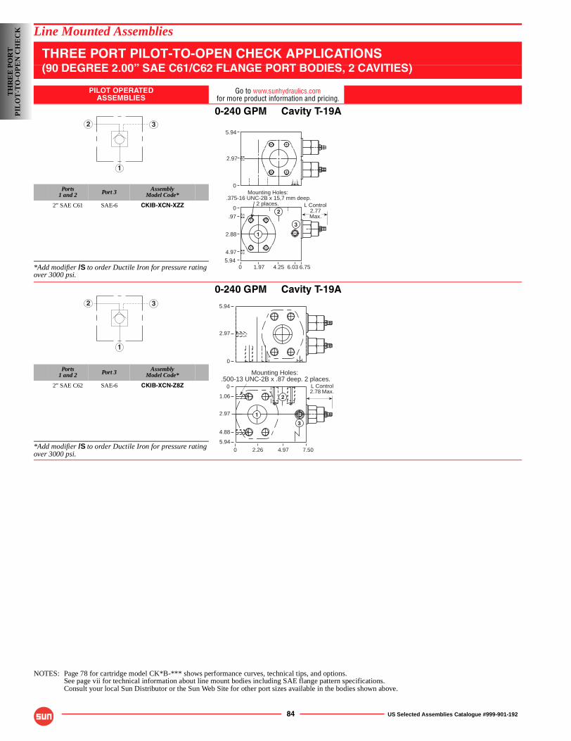
84 US Selected Assemblies Catalogue #999-901-192
Line Mounted Assemblies
THREE PORT PILOT-TO-OPEN CHECK APPLICATIONS(90 DEGREE 2.00” SAE C61/C62 FLANGE PORT BODIES, 2 CAVITIES)
PILOT OPERATEDASSEMBLIES
Go to www.sunhydraulics.comfor more product information and pricing.
0-240 GPM Cavity T-19A
Ports1 and 2 Port 3 Assembly
Model Code*
2” SAE C61 SAE-6 CKIB-XCN-XZZ
*Add modifier /S to order Ductile Iron for pressure rating over 3000 psi.
0-240 GPM Cavity T-19A
Ports1 and 2 Port 3 Assembly
Model Code*
2” SAE C62 SAE-6 CKIB-XCN-Z8Z
*Add modifier /S to order Ductile Iron for pressure rating over 3000 psi.
NOTES: Page 78 for cartridge model CK*B-*** shows performance curves, technical tips, and options.See page vii for technical information about line mount bodies including SAE flange pattern specifications.Consult your local Sun Distributor or the Sun Web Site for other port sizes available in the bodies shown above.
1
2 35.94
2.97
0
3
L Control2.77Max.
1
2
6.756.034.251.9705.94
4.97
2.88
.97
0
Mounting Holes:.375-16 UNC-2B x 15,7 mm deep.
2 places.
1
2 3
L Control2.78 Max.
5.94
2.97
0
Mounting Holes:.500-13 UNC-2B x .87 deep. 2 places.
0
0
1.06
2.97
5.94
4.972.26
4.88
7.50
1
2
3
TH
RE
E P
OR
TP
ILO
T-T
O-O
PE
N C
HE
CK
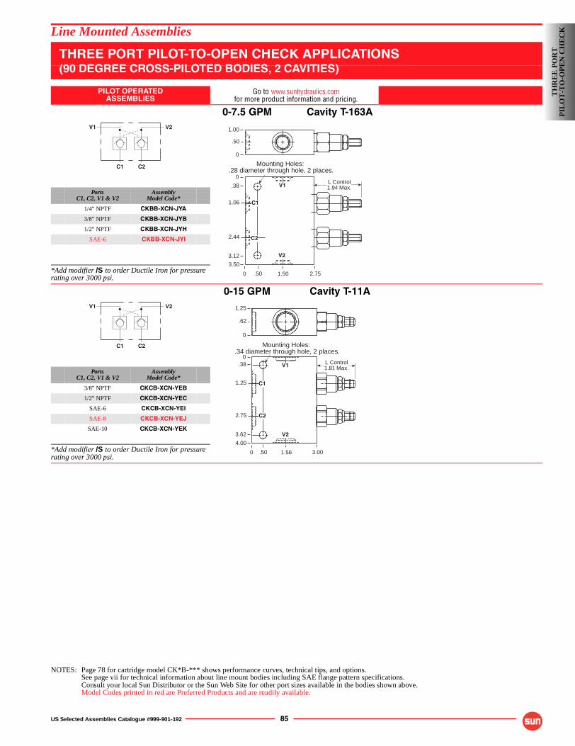
US Selected Assemblies Catalogue #999-901-192 85
Line Mounted Assemblies
THREE PORT PILOT-TO-OPEN CHECK APPLICATIONS(90 DEGREE CROSS-PILOTED BODIES, 2 CAVITIES)
PILOT OPERATEDASSEMBLIES
Go to www.sunhydraulics.comfor more product information and pricing.
0-7.5 GPM Cavity T-163A
PortsC1, C2, V1 & V2
AssemblyModel Code*
1/4” NPTF CKBB-XCN-JYA
3/8” NPTF CKBB-XCN-JYB
1/2” NPTF CKBB-XCN-JYH
SAE-6 CKBB-XCN-JYI
*Add modifier /S to order Ductile Iron for pressure rating over 3000 psi.
0-15 GPM Cavity T-11A
PortsC1, C2, V1 & V2
AssemblyModel Code*
3/8” NPTF CKCB-XCN-YEB
1/2” NPTF CKCB-XCN-YEC
SAE-6 CKCB-XCN-YEI
SAE-8 CKCB-XCN-YEJ
SAE-10 CKCB-XCN-YEK
*Add modifier /S to order Ductile Iron for pressure rating over 3000 psi.
NOTES: Page 78 for cartridge model CK*B-*** shows performance curves, technical tips, and options.See page vii for technical information about line mount bodies including SAE flange pattern specifications.Consult your local Sun Distributor or the Sun Web Site for other port sizes available in the bodies shown above.Model Codes printed in red are Preferred Products and are readily available.
C1 C2
V2V1
0
0
.38
2.44
3.50
2.751.50.50
L Control1.94 Max.
Mounting Holes:.28 diameter through hole, 2 places.
1.00
.50
0
3.12
1.06 C1
C2
V2
V1
C1 C2
V2V1
0
0.38
2.75
4.00
3.001.56.50
L Control1.81 Max.
Mounting Holes:.34 diameter through hole, 2 places.
C1
C2
V1
1.25
.62
0
3.62
1.25
V2
TH
RE
E P
OR
TP
ILO
T-T
O-O
PE
N C
HE
CK
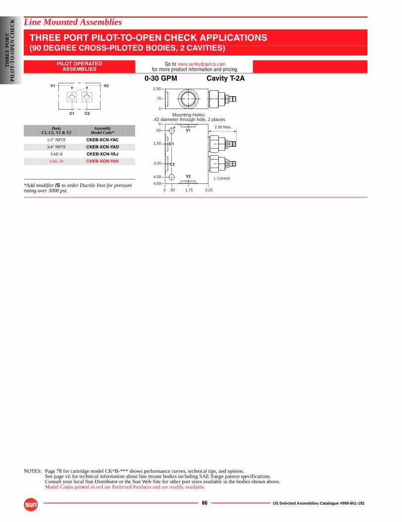
86 US Selected Assemblies Catalogue #999-901-192
Line Mounted Assemblies
THREE PORT PILOT-TO-OPEN CHECK APPLICATIONS(90 DEGREE CROSS-PILOTED BODIES, 2 CAVITIES)
PILOT OPERATEDASSEMBLIES
Go to www.sunhydraulics.comfor more product information and pricing.
0-30 GPM Cavity T-2A
PortsC1, C2, V1 & V2
AssemblyModel Code*
1/2” NPTF CKEB-XCN-YAC
3/4” NPTF CKEB-XCN-YAD
SAE-8 CKEB-XCN-YAJ
SAE-10 CKEB-XCN-YAK
*Add modifier /S to order Ductile Iron for pressure rating over 3000 psi.
NOTES: Page 78 for cartridge model CK*B-*** shows performance curves, technical tips, and options.See page vii for technical information about line mount bodies including SAE flange pattern specifications.Consult your local Sun Distributor or the Sun Web Site for other port sizes available in the bodies shown above.Model Codes printed in red are Preferred Products and are readily available.
C1 C2
V2V1
2.06 Max.
L Control
0
0
.50
3.00
4.50
3.251.75.50
Mounting Holes:.42 diameter through hole, 2 places.
C1
C2
V1
1.50
.75
0
4.00
1.50
V2
TH
RE
E P
OR
TP
ILO
T-T
O-O
PE
N C
HE
CK
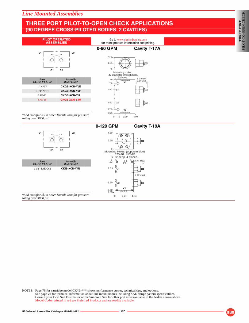
US Selected Assemblies Catalogue #999-901-192 87
Line Mounted Assemblies
THREE PORT PILOT-TO-OPEN CHECK APPLICATIONS(90 DEGREE CROSS-PILOTED BODIES, 2 CAVITIES)
PILOT OPERATEDASSEMBLIES
Go to www.sunhydraulics.comfor more product information and pricing.
0-60 GPM Cavity T-17A
PortsC1, C2, V1 & V2
AssemblyModel Code*
1” NPTF CKGB-XCN-YJE
1 1/4” NPTF CKGB-XCN-YJF
SAE-12 CKGB-XCN-YJL
SAE-16 CKGB-XCN-YJM
*Add modifier /S to order Ductile Iron for pressure rating over 3000 psi.
0-120 GPM Cavity T-19A
PortsC1, C2, V1 & V2
AssemblyModel Code*
1 1/2” SAE C62 CKIB-XCN-YM6
*Add modifier /S to order Ductile Iron for pressure rating over 3000 psi.
NOTES: Page 78 for cartridge model CK*B-*** shows performance curves, technical tips, and options.See page vii for technical information about line mount bodies including SAE flange pattern specifications.Consult your local Sun Distributor or the Sun Web Site for other port sizes available in the bodies shown above.Model Codes printed in red are Preferred Products and are readily available.
C1 C2
V2V1
L Control2.37 Max.
0
0
.75
4.50
6.50
4.002.09.75
Mounting Holes:.42 diameter through hole,
2 places.
2.25
1.12
0
5.75
2.00 C1
C2
V2
V1
C1 C2
V2V1
2.78 Max.
0
0
6.50
9.03
4.942.41
Mounting Holes: (opposite side).375-16 UNC-2B
x .62 deep. 4 places.
4.50
2.25
0
2.53 C1
C2
V1
V2
L Control
.52
8.52
TH
RE
E P
OR
TP
ILO
T-T
O-O
PE
N C
HE
CK
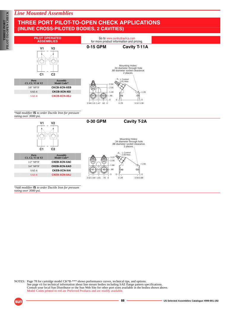
88 US Selected Assemblies Catalogue #999-901-192
Line Mounted Assemblies
THREE PORT PILOT-TO-OPEN CHECK APPLICATIONS(INLINE CROSS-PILOTED BODIES, 2 CAVITIES)
PILOT OPERATEDASSEMBLIES
Go to www.sunhydraulics.comfor more product information and pricing.
0-15 GPM Cavity T-11A
PortsC1, C2, V1 & V2
AssemblyModel Code*
3/8” NPTF CKCB-XCN-XEB
SAE-6 CKCB-XCN-XEI
SAE-8 CKCB-XCN-XEJ
*Add modifier /S to order Ductile Iron for pressure rating over 3000 psi.
0-30 GPM Cavity T-2A
PortsC1, C2, V1 & V2
AssemblyModel Code*
1/2” NPTF CKEB-XCN-XAC
3/4” NPTF CKEB-XCN-XAD
SAE-6 CKEB-XCN-XAI
SAE-8 CKEB-XCN-XAJ
*Add modifier /S to order Ductile Iron for pressure rating over 3000 psi.
NOTES: Page 78 for cartridge model CK*B-*** shows performance curves, technical tips, and options.See page vii for technical information about line mount bodies including SAE flange pattern specifications.Consult your local Sun Distributor or the Sun Web Site for other port sizes available in the bodies shown above.Model Codes printed in red are Preferred Products and are readily available.
C1 C2
V1 V2
L Control1.81 Max.
Mounting Holes:.34 diameter through hole
.88 diameter socket clearance.2 places.
0
2.05
1.28
.66
0
3.383.10.292.94
1.28
0
.62
2.64
0
0
1.472.31
V1 V2 C2V2
C1 C2
V1 V2
L Control2.09 Max.
2.56
1.66
.88
0
3.883.593.62
1.66
0
.78
3.22
01.812.84
V1 V2
Mounting Holes:.34 diameter through hole
.88 diameter socket clearance.2 places.
0.28
0
V2 C2
TH
RE
E P
OR
TP
ILO
T-T
O-O
PE
N C
HE
CK
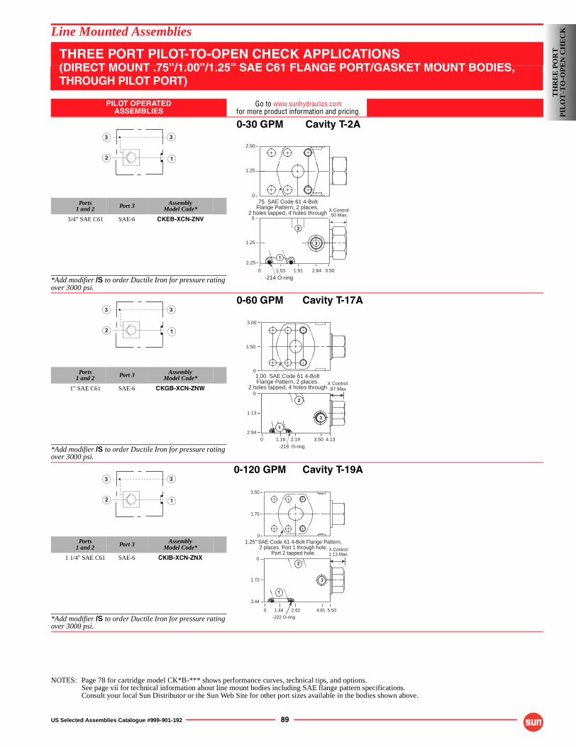
US Selected Assemblies Catalogue #999-901-192 89
Line Mounted Assemblies
THREE PORT PILOT-TO-OPEN CHECK APPLICATIONS(DIRECT MOUNT .75”/1.00”/1.25” SAE C61 FLANGE PORT/GASKET MOUNT BODIES,THROUGH PILOT PORT)
PILOT OPERATEDASSEMBLIES
Go to www.sunhydraulics.comfor more product information and pricing.
0-30 GPM Cavity T-2A
Ports1 and 2 Port 3 Assembly
Model Code*
3/4” SAE C61 SAE-6 CKEB-XCN-ZNV
*Add modifier /S to order Ductile Iron for pressure rating over 3000 psi.
0-60 GPM Cavity T-17A
Ports1 and 2 Port 3 Assembly
Model Code*
1” SAE C61 SAE-6 CKGB-XCN-ZNW
*Add modifier /S to order Ductile Iron for pressure rating over 3000 psi.
0-120 GPM Cavity T-19A
Ports1 and 2 Port 3 Assembly
Model Code*
1 1/4” SAE C61 SAE-6 CKIB-XCN-ZNX
*Add modifier /S to order Ductile Iron for pressure rating over 3000 psi.
NOTES: Page 78 for cartridge model CK*B-*** shows performance curves, technical tips, and options.See page vii for technical information about line mount bodies including SAE flange pattern specifications.Consult your local Sun Distributor or the Sun Web Site for other port sizes available in the bodies shown above.
1
3
2
3
0
0
1.25
2.25
3.502.84
-214 O-ring
1
2
3
1.911.03
X Control.50 Max.
.75 SAE Code 61 4-BoltFlange Pattern, 2 places.
2 holes tapped, 4 holes through
2.50
1.25
0
1
3
2
3
X Control
2.94
1.13
0
0 1.16 2.19 3.50 4.13
2
3
-219 O-ring
1
.87 Max
1.00 SAE Code 61 4-BoltFlange Pattern, 2 places.
2 holes tapped, 4 holes through
3.00
1.50
0
1
3
2
3
1
20
1.72
3.44
0 1.44 2.62 4.81 5.50
-222 O-ring
X Control1.13 Max.
3
1.25” SAE Code 61 4-Bolt Flange Pattern,2 places. Port 1 through hole.
Port 2 tapped hole.
3.50
1.75
0
TH
RE
E P
OR
TP
ILO
T-T
O-O
PE
N C
HE
CK
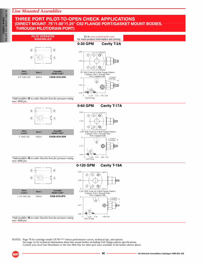
90 US Selected Assemblies Catalogue #999-901-192
Line Mounted Assemblies
THREE PORT PILOT-TO-OPEN CHECK APPLICATIONS(DIRECT MOUNT .75”/1.00”/1.25” C62 FLANGE PORT/GASKET MOUNT BODIES, THROUGH PILOT/DRAIN PORT)
PILOT OPERATEDASSEMBLIES
Go to www.sunhydraulics.comfor more product information and pricing.
0-30 GPM Cavity T-2A
Ports1 and 2 Port 3 Assembly
Model Code*
3/4” SAE C62 SAE-6 CKEB-XCN-ZDS
*Add modifier /S to order Ductile Iron for pressure rating over 3000 psi.
0-60 GPM Cavity T-17A
Ports1 and 2 Port 3 Assembly
Model Code*
1” SAE C62 SAE-6 CKGB-XCN-ZDR
*Add modifier /S to order Ductile Iron for pressure rating over 3000 psi.
0-120 GPM Cavity T-19A
Ports1 and 2 Port 3 Assembly
Model Code*
1 1/4” SAE C62 SAE-6 CKIB-XCN-ZFD
*Add modifier /S to order Ductile Iron for pressure rating over 3000 psi.
NOTES: Page 78 for cartridge model CK*B-*** shows performance curves, technical tips, and options.See page vii for technical information about line mount bodies including SAE flange pattern specifications.Consult your local Sun Distributor or the Sun Web Site for other port sizes available in the bodies shown above.
1
3
2
3
L Control2.09 Max.
0
0
1.22
2.44
3.533.03
1
2
3
2.121.19-214 O-ring
3.00
1.50
0.75” SAE Code 62 4-Bolt Flange Pattern,
2 places. Port 1 through hole.Port 2 tapped hole.
1
3
2
3
0
0
1.72
3.44
4.313.692.471.38-219 O-ring
L Control2.34 Max.
1
3
2
3.50
1.75
01.00” SAE Code 62 4-Bolt Flange Pattern,
2 places. Port 1 through hole.Port 2 tapped hole.
1
3
2
3
0
0
1.97
3.94
5.624.88
1
2
3
2.781.53-222 O-ring
L Control2.75 Max.
4.00
2.00
0
1.25” SAE Code 62 4-Bolt Flange Pattern,2 places. Port 1 through hole.
Port 2 tapped hole.
TH
RE
E P
OR
TP
ILO
T-T
O-O
PE
N C
HE
CK
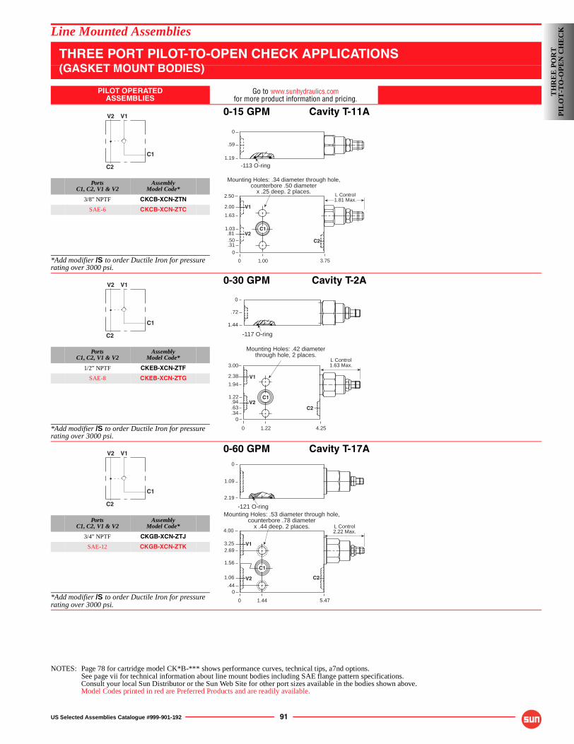
US Selected Assemblies Catalogue #999-901-192 91
Line Mounted Assemblies
THREE PORT PILOT-TO-OPEN CHECK APPLICATIONS(GASKET MOUNT BODIES)
PILOT OPERATEDASSEMBLIES
Go to www.sunhydraulics.comfor more product information and pricing.
0-15 GPM Cavity T-11A
PortsC1, C2, V1 & V2
AssemblyModel Code*
3/8” NPTF CKCB-XCN-ZTN
SAE-6 CKCB-XCN-ZTC
*Add modifier /S to order Ductile Iron for pressure rating over 3000 psi.
0-30 GPM Cavity T-2A
PortsC1, C2, V1 & V2
AssemblyModel Code*
1/2” NPTF CKEB-XCN-ZTF
SAE-8 CKEB-XCN-ZTG
*Add modifier /S to order Ductile Iron for pressure rating over 3000 psi.
0-60 GPM Cavity T-17A
PortsC1, C2, V1 & V2
AssemblyModel Code*
3/4” NPTF CKGB-XCN-ZTJ
SAE-12 CKGB-XCN-ZTK
*Add modifier /S to order Ductile Iron for pressure rating over 3000 psi.
NOTES: Page 78 for cartridge model CK*B-*** shows performance curves, technical tips, a7nd options.See page vii for technical information about line mount bodies including SAE flange pattern specifications.Consult your local Sun Distributor or the Sun Web Site for other port sizes available in the bodies shown above.Model Codes printed in red are Preferred Products and are readily available.
V2 V1
C1
C2
0
2.50
1.63
.81
0
3.75
Mounting Holes: .34 diameter through hole,counterbore .50 diameter
x .25 deep. 2 places.
0
.59
1.19
V2
1.00
V1
C2
2.00
1.03
.31
-113 O-ring
.50
L Control1.81 Max.
C1C1
V2 V1
C1
C2
L Control1.63 Max.
0
3.00
.94
0
4.25
Mounting Holes: .42 diameterthrough hole, 2 places.
.72
1.22
2.38
1.22 C1
V1
V2C2
.34
-117 O-ring
1.94
.63
1.44
0
C1
V2 V1
C1
C2
L Control2.22 Max.
0
4.00
2.69
1.06
0
5.47
Mounting Holes: .53 diameter through hole,counterbore .78 diameter
x .44 deep. 2 places.
0
1.09
2.19
V2
1.44
V1
C1
C2
3.25
1.56
.44
-121 O-ring
C1
TH
RE
E P
OR
TP
ILO
T-T
O-O
PE
N C
HE
CK
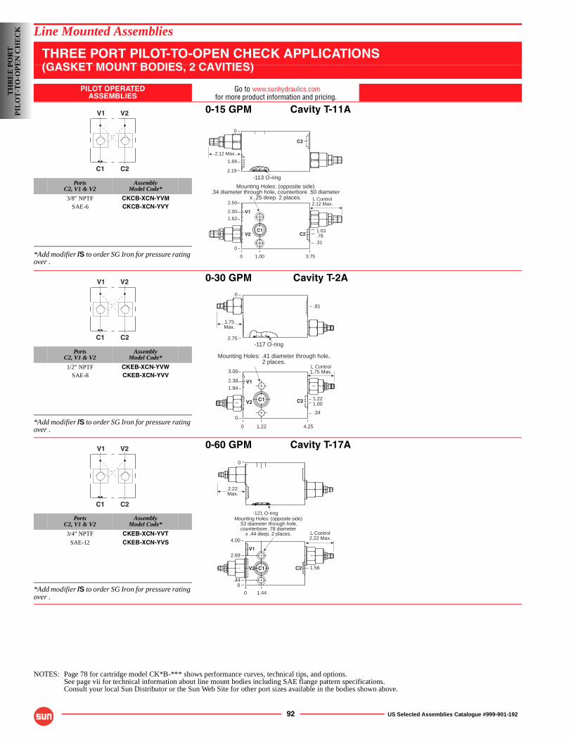
92 US Selected Assemblies Catalogue #999-901-192
Line Mounted Assemblies
THREE PORT PILOT-TO-OPEN CHECK APPLICATIONS(GASKET MOUNT BODIES, 2 CAVITIES)
PILOT OPERATEDASSEMBLIES
Go to www.sunhydraulics.com
0-15 GPM Cavity T-11A
PortsC2, V1 & V2
AssemblyModel Code*
3/8” NPTF CKCB-XCN-YVMSAE-6 CKCB-XCN-YVY
*Add modifier /S to order SG Iron for pressure rating over .
0-30 GPM Cavity T-2A
PortsC2, V1 & V2
AssemblyModel Code*
1/2” NPTF CKEB-XCN-YVWSAE-8 CKEB-XCN-YVV
*Add modifier /S to order SG Iron for pressure rating over .
0-60 GPM Cavity T-17A
PortsC2, V1 & V2
AssemblyModel Code*
3/4” NPTF CKEB-XCN-YVTSAE-12 CKEB-XCN-YVS
*Add modifier /S to order SG Iron for pressure rating over .
NOTES: Page 78 for cartridge model CK*B-*** shows performance curves, technical tips, and options.See page vii for technical information about line mount bodies including SAE flange pattern specifications.Consult your local Sun Distributor or the Sun Web Site for other port sizes available in the bodies shown above.
C1 C2
V1 V2
L Control2.12 Max.
0
2.50
.78
0
3.75
Mounting Holes: (opposite side).34 diameter through hole, counterbore .50 diameter
x .25 deep. 2 places.
0
1.69
2.19
1.00
2.00
1.03
V1
V2 C2
.31
-113 O-ring
1.62
C1
2.12 Max.
C2
C1 C2
V1 V2
0 4.251.22
L Control1.75 Max.3.00
1.00
0
Mounting Holes: .41 diameter through hole,2 places.
0
.81
2.75
2.38
1.22
V1
V2 C2
.34
-117 O-ring
1.94
C1
1.75Max.
C1 C2
V1 V2
-121 O-ring
0
L Control2.22 Max.
0
4.00
0
Mounting Holes: (opposite side).53 diameter through hole,counterbore .78 diameter
x .44 deep. 2 places.
1.44
1.56
.44
2.69V1
C2V2 C1
2.22Max.
TH
RE
E P
OR
TP
ILO
T-T
O-O
PE
N C
HE
CK
for more product information and pricing.
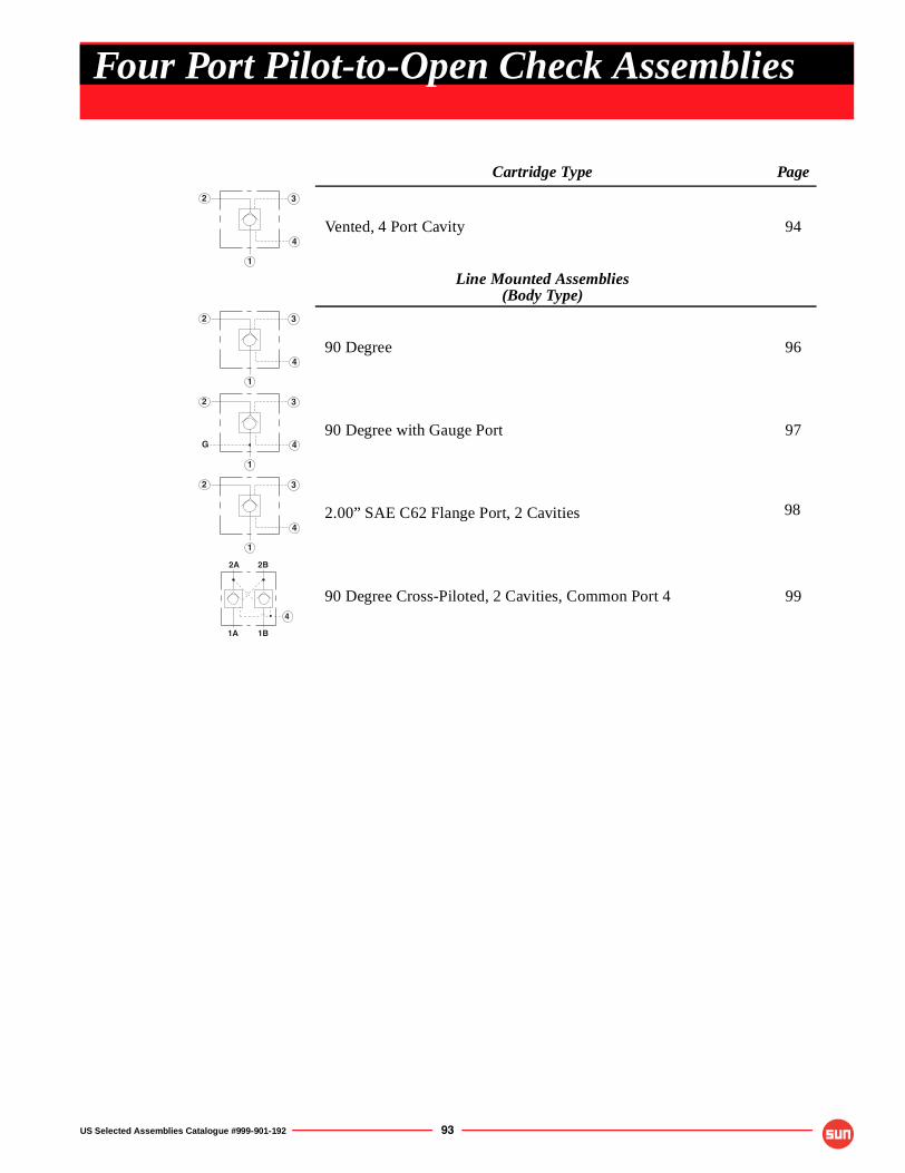
US Selected Assemblies Catalogue #999-901-192 93
Cartridge Type Page
Vented, 4 Port Cavity 94
Line Mounted Assemblies(Body Type)
90 Degree 96
90 Degree with Gauge Port 97
2.00” SAE C62 Flange Port, 2 Cavities
90 Degree Cross-Piloted, 2 Cavities, Common Port 4 99
1
2 3
4
1
2 3
4
1
2 3
4G
1
2 3
4
1A 1B
2A 2B
4
Four Port Pilot-to-Open Check Assemblies
98
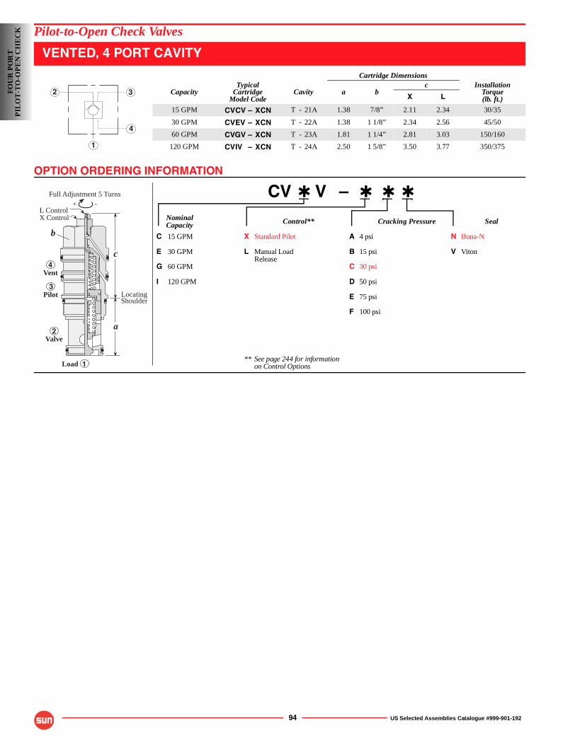
OPTION ORDERING INFORMATION
94 US Selected Assemblies Catalogue #999-901-192
Pilot-to-Open Check Valves
VENTED, 4 PORT CAVITY
CV ✱ V – ✱ ✱ ✱
Nominal Control** Cracking Pressure SealCapacity
C 15 GPM X Standard Pilot A 4 psi N Buna-N
E 30 GPM L Manual Load B 15 psi V VitonRelease
G 60 GPM C 30 psi
I 120 GPM D 50 psi
E 75 psi
F 100 psi
** See page 244 for informationon Control Options
Cartridge Dimensions
CapacityTypical
CartridgeModel Code
Cavity a bc Installation
Torque(lb. ft.)X L
15 GPM CVCV – XCN T - 21A 1.38 7/8” 2.11 2.34 30/35
30 GPM CVEV – XCN T - 22A 1.38 1 1/8” 2.34 2.56 45/50
60 GPM CVGV – XCN T - 23A 1.81 1 1/4” 2.81 3.03 150/160
120 GPM CVIV – XCN T - 24A 2.50 1 5/8” 3.50 3.77 350/3751
2 3
4
-+
Full Adjustment 5 Turns
b
4
3
2
1
c
a
L ControlX Control
Load
Valve
Pilot
Vent
LocatingShoulder
FOU
R P
OR
TP
ILO
T-T
O-O
PE
N C
HE
CK
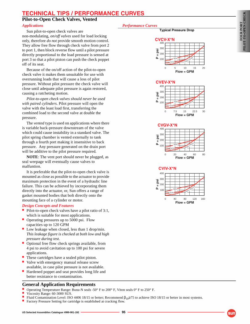
TECHNICAL TIPS / PERFORMANCE CURVES
US Selected Assemblies Catalogue #999-901-192 95
Pilot-to-Open Check Valves, VentedApplications
Sun pilot-to-open check valves are non-modulating, on/off valves used for load locking only, therefore do not provide smooth motion control. They allow free flow through check valve from port 2 to port 1, then block reverse flow until a pilot pressure directly proportional to the load pressure is sensed at port 3 so that a pilot piston can push the check poppet off of its seat.
Because of the on/off action of the pilot-to-open check valve it makes them unsuitable for use with overrunning loads that will cause a loss of pilot pressure. Without pilot pressure the check valve will close until adequate pilot pressure is again restored, causing a ratcheting motion.
Pilot-to-open check valves should never be used with paired cylinders. Pilot pressure will open the valve with the least load first, transferring the combined load to the second valve at double the pressure.
The vented type is used on applications where there is variable back-pressure downstream of the valve which could cause instability in a standard valve. The pilot spring chamber is vented externally to tank through a fourth port making it insensitive to back pressure. Any pressure generated on the drain port will be additive to the pilot pressure required.
NOTE: The vent port should never be plugged, as seal weepage will eventually cause valves to malfuntion.
It is preferable that the pilot-to-open check valve is mounted as close as possible to the actuator to provide maximum protection in the event of a hydraulic line failure. This can be achieved by incorporating them directly into the actuator, or, Sun offers a range of gasket mounted bodies that bolt directly onto the mounting face of a cylinder or motor.Design Concepts and Features■ Pilot-to-open check valves have a pilot ratio of 3:1,
which is suitable for most applications.■ Operating pressures up to 5000 psi. Flow
capacities up to 120 GPM■ Low leakage when closed, less than 1 drop/min.
This leakage figure is checked at both low and high pressure during test.
■ Optional free flow check springs available, from 4 psi to avoid cavitation up to 100 psi for severe applications.
■ These cartridges have a sealed pilot piston.■ Valve with emergency manual release screw
available, in case pilot pressure is not available.■ Hardened poppet and seat provides long life and
better resistance to contamination.
Performance CurvesTypical Pressure Drop
400
300
200
0 307.5 22.5
Flow = GPM
P =
psi
100 XEN
XCN FULL PILOT
15
400
300
200
0 80 40 60Flow = GPM
P =
psi
100
20
XEN
XCN FULL PILOT
400
300
200
0 160120 40 80
100
Flow = GPM
P =
psi
XEN
XCN FULL PILOT
400
300
200
0 20 5 10 15
Flow = GPM
P =
psi
100 XEN
XCN FULL PILOT
CVCV-X*N
CVEV-X*N
CVGV-X*N
CVIV-X*N
FOU
R P
OR
TP
ILO
T-T
O-O
PE
N C
HE
CK
General Application Requirements■ Operating Temperature Range: Buna-N seals -50° F to 200° F, Viton seals 0° F to 250° F.■ Viscosity Range: 60-3000 SUS.■ Fluid Contamination Level: ISO 4406 18/15 or better; Recommend β10≥75 to achieve ISO 18/15 or better in most systems.■ Factory Pressure Setting for cartridge is established at cracking flow.
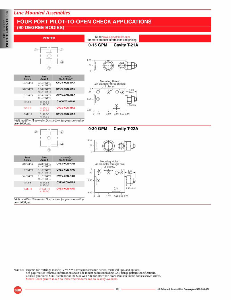
96 US Selected Assemblies Catalogue #999-901-192
Line Mounted Assemblies
FOUR PORT PILOT-TO-OPEN CHECK APPLICATIONS(90 DEGREE BODIES)
VENTED Go to www.sunhydraulics.comfor more product information and pricing.
0-15 GPM Cavity T-21A
Ports1 and 2
Ports3 and 4
AssemblyModel Code*
1/4” NPTF 3: 1/4” NPTF4: 1/4” NPTF
CVCV-XCN-MAA
3/8” NPTF 3: 3/8” NPTF4: 1/4” NPTF
CVCV-XCN-MAB
1/2” NPTF 3: 3/8” NPTF4: 1/4” NPTF
CVCV-XCN-MAC
SAE-6 3: SAE-64: SAE-6
CVCV-XCN-MAI
SAE-8 3: SAE-84: SAE-6
CVCV-XCN-MAJ
SAE-10 3: SAE-84: SAE-6
CVCV-XCN-MAK
*Add modifier /S to order Ductile Iron for pressure rating over 3000 psi.
0-30 GPM Cavity T-22A
Ports1 and 2
Ports3 and 4
AssemblyModel Code*
3/8” NPTF 3: 3/8” NPTF4: 1/4” NPTF
CVEV-XCN-NAB
1/2” NPTF 3: 1/2” NPTF4: 1/4” NPTF
CVEV-XCN-NAC
3/4” NPTF 3: 1/2” NPTF4: 1/4” NPTF
CVEV-XCN-NAD
SAE-8 3: SAE-84: SAE-6
CVEV-XCN-NAJ
SAE-10 3: SAE-104: SAE-6
CVEV-XCN-NAK
*Add modifier /S to order Ductile Iron for pressure rating over 3000 psi.
NOTES: Page 94 for cartridge model CV*V-*** shows performance curves, technical tips, and options.See page vii for technical information about line mount bodies including SAE flange pattern specifications.Consult your local Sun Distributor or the Sun Web Site for other port sizes available in the bodies shown above.Model Codes printed in red are Preferred Products and are readily available.
1
2 3
4
1.09 Max.
1.25
.62
0
0
0.38
1.25
2.50
3.562.561.59
Mounting Holes:.34 diameter through hole
2 places.
1
2
3
4
.44 3.12
L Control
1
2 3
4
1.25 Max.
Mounting Holes:.42 diameter through hole
2 places.
0
0
.50
1.50
3.00
3.752.691.72
1.50
.75
0
.44 3.31
L Control
1
2
3
4
FOU
R P
OR
TP
ILO
T-T
O-O
PE
N C
HE
CK
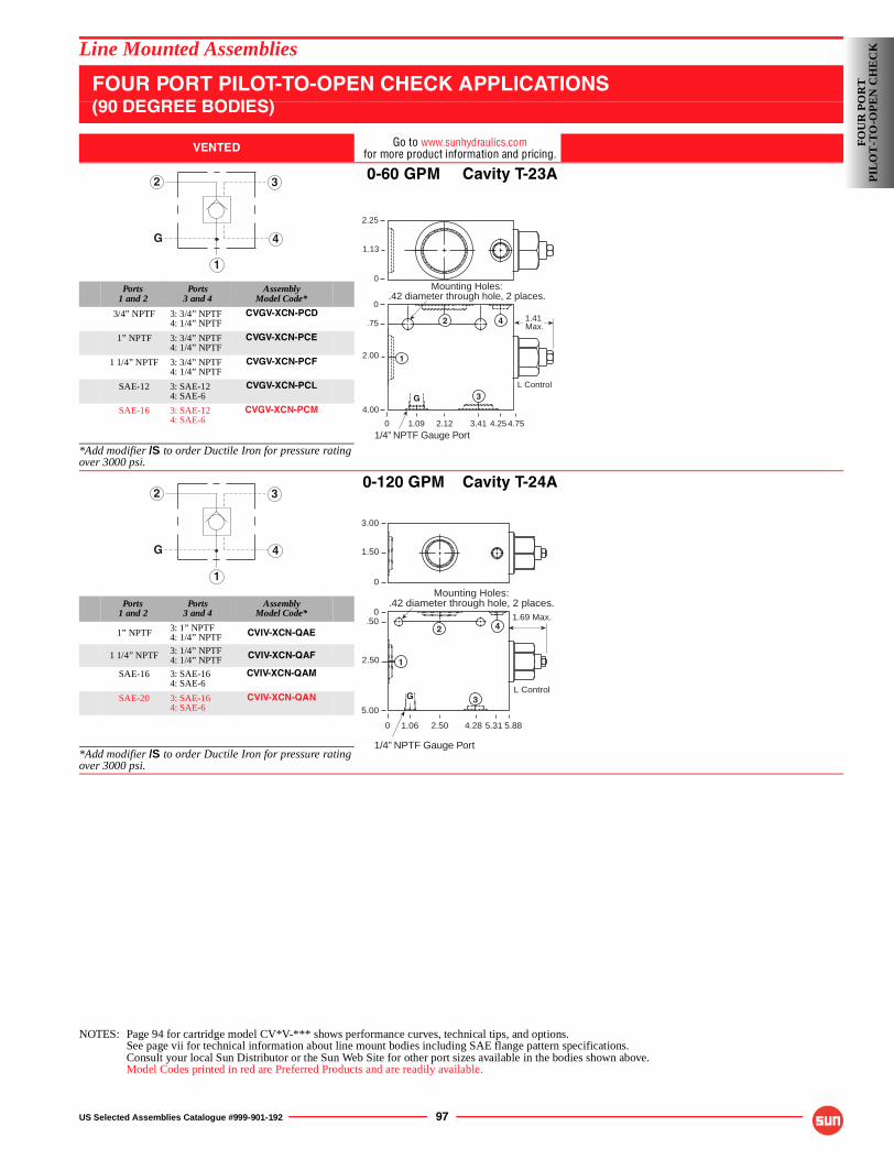
US Selected Assemblies Catalogue #999-901-192 97
Line Mounted Assemblies
FOUR PORT PILOT-TO-OPEN CHECK APPLICATIONS(90 DEGREE BODIES)
VENTED Go to www.sunhydraulics.comfor more product information and pricing.
0-60 GPM Cavity T-23A
Ports1 and 2
Ports3 and 4
AssemblyModel Code*
3/4” NPTF 3: 3/4” NPTF4: 1/4” NPTF
CVGV-XCN-PCD
1” NPTF 3: 3/4” NPTF4: 1/4” NPTF
CVGV-XCN-PCE
1 1/4” NPTF 3: 3/4” NPTF4: 1/4” NPTF
CVGV-XCN-PCF
SAE-12 3: SAE-124: SAE-6
CVGV-XCN-PCL
SAE-16 3: SAE-124: SAE-6
CVGV-XCN-PCM
*Add modifier /S to order Ductile Iron for pressure rating over 3000 psi.
0-120 GPM Cavity T-24A
Ports1 and 2
Ports3 and 4
AssemblyModel Code*
1” NPTF 3: 1” NPTF4: 1/4” NPTF CVIV-XCN-QAE
1 1/4” NPTF 3: 1/4” NPTF4: 1/4” NPTF CVIV-XCN-QAF
SAE-16 3: SAE-164: SAE-6
CVIV-XCN-QAM
SAE-20 3: SAE-164: SAE-6
CVIV-XCN-QAN
*Add modifier /S to order Ductile Iron for pressure rating over 3000 psi.
NOTES: Page 94 for cartridge model CV*V-*** shows performance curves, technical tips, and options.See page vii for technical information about line mount bodies including SAE flange pattern specifications.Consult your local Sun Distributor or the Sun Web Site for other port sizes available in the bodies shown above.Model Codes printed in red are Preferred Products and are readily available.
1
2 3
4G
2.25
1.13
0
0
0
.75
2.00
4.00
4.253.412.12
1.41 Max.
Mounting Holes:.42 diameter through hole, 2 places.
L Control
1.09 4.75
1
2
3
4
G
1/4” NPTF Gauge Port
1
2 3
4G
3.00
1.50
0
1/4” NPTF Gauge Port
0
0.50
2.50
5.00
5.884.282.50
1.69 Max.
Mounting Holes:.42 diameter through hole, 2 places.
5.311.06
L Control
1
2 4
G 3
FOU
R P
OR
TP
ILO
T-T
O-O
PE
N C
HE
CK
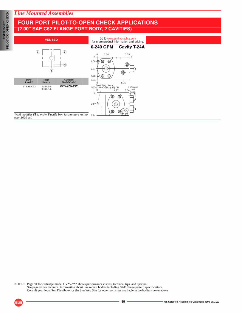
98 US Selected Assemblies Catalogue #999-901-192
Line Mounted Assemblies
FOUR PORT PILOT-TO-OPEN CHECK APPLICATIONS(2.00” SAE C62 FLANGE PORT BODY, 2 CAVITIES)
VENTED Go to www.sunhydraulics.comfor more product information and pricing.
0-240 GPM Cavity T-24A
Ports1 and 2
Ports3 and 4
AssemblyModel Code*
2” SAE C62 3: SAE-64: SAE-6
CVIV-XCN-Z9T
*Add modifier /S to order Ductile Iron for pressure rating over 3000 psi.
NOTES: Page 94 for cartridge model CV*V-*** shows performance curves, technical tips, and options.See page vii for technical information about line mount bodies including SAE flange pattern specifications.Consult your local Sun Distributor or the Sun Web Site for other port sizes available in the bodies shown above.
1
2 3
4
2.260 7.7800
1.06
2.97
4.88
5.940 6.75
8.344.9700
2.97
5.94
Mounting Holes:.500-13 UNC-2B x (.87) DP.
1.69Max.
L Control
1
2
3 4
FOU
R P
OR
TP
ILO
T-T
O-O
PE
N C
HE
CK
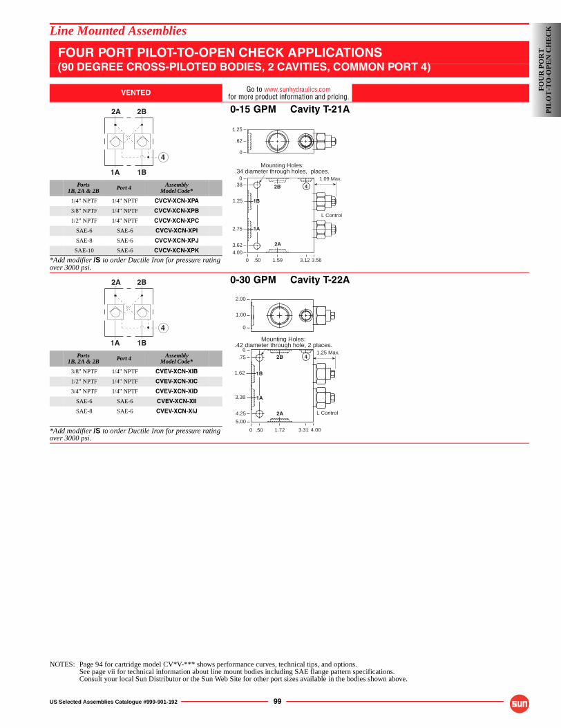
US Selected Assemblies Catalogue #999-901-192 99
Line Mounted Assemblies
FOUR PORT PILOT-TO-OPEN CHECK APPLICATIONS(90 DEGREE CROSS-PILOTED BODIES, 2 CAVITIES, COMMON PORT 4)
VENTED Go to www.sunhydraulics.comfor more product information and pricing.
0-15 GPM Cavity T-21A
Ports1B, 2A & 2B Port 4 Assembly
Model Code*
1/4” NPTF 1/4” NPTF CVCV-XCN-XPA
3/8” NPTF 1/4” NPTF CVCV-XCN-XPB
1/2” NPTF 1/4” NPTF CVCV-XCN-XPC
SAE-6 SAE-6 CVCV-XCN-XPI
SAE-8 SAE-6 CVCV-XCN-XPJ
SAE-10 SAE-6 CVCV-XCN-XPK
*Add modifier /S to order Ductile Iron for pressure rating over 3000 psi.
0-30 GPM Cavity T-22A
Ports1B, 2A & 2B Port 4 Assembly
Model Code*
3/8” NPTF 1/4” NPTF CVEV-XCN-XIB
1/2” NPTF 1/4” NPTF CVEV-XCN-XIC
3/4” NPTF 1/4” NPTF CVEV-XCN-XID
SAE-6 SAE-6 CVEV-XCN-XII
SAE-8 SAE-6 CVEV-XCN-XIJ
*Add modifier /S to order Ductile Iron for pressure rating over 3000 psi.
NOTES: Page 94 for cartridge model CV*V-*** shows performance curves, technical tips, and options.See page vii for technical information about line mount bodies including SAE flange pattern specifications.Consult your local Sun Distributor or the Sun Web Site for other port sizes available in the bodies shown above.
1A 1B
2A 2B
4
1.09 Max.
1.25
.62
0
Mounting Holes:.34 diameter through holes, places.
0
0.38
2.75
4.00
3.121.59
3.62
3.56
1.25
.50
L Control
1B
1A
2B
2A
4
1A 1B
2A 2B
4
1.25 Max.
0
0
.75
3.38
5.00
4.001.72.50
Mounting Holes:.42 diameter through hole, 2 places.
2.00
1.00
0
4.25
1.62
3.31
L Control
1B
1A
2B
2A
4
FOU
R P
OR
TP
ILO
T-T
O-O
PE
N C
HE
CK
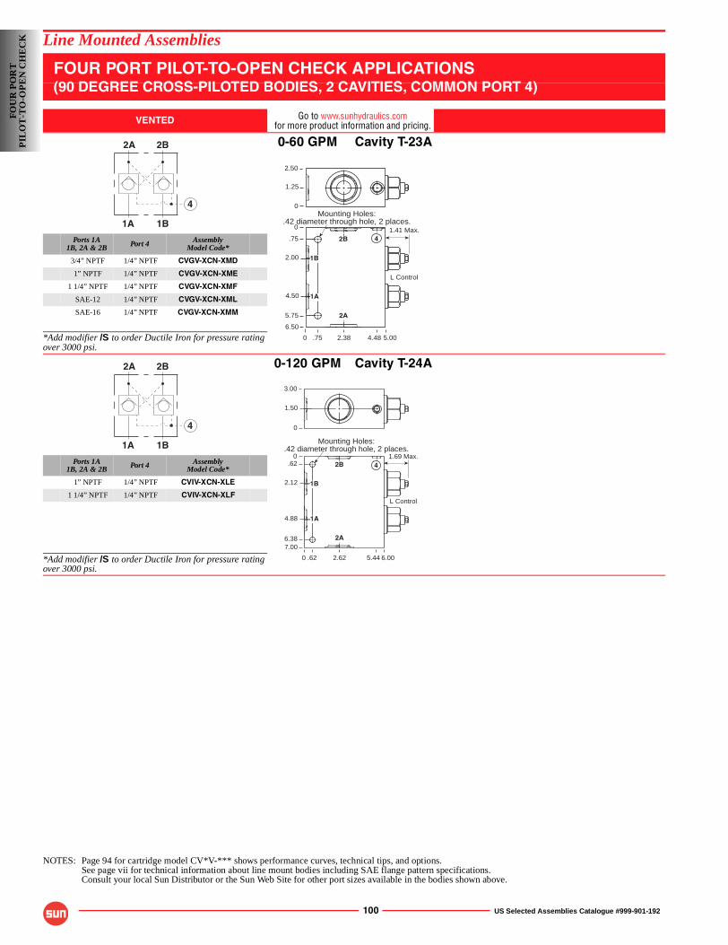
100 US Selected Assemblies Catalogue #999-901-192
Line Mounted Assemblies
FOUR PORT PILOT-TO-OPEN CHECK APPLICATIONS(90 DEGREE CROSS-PILOTED BODIES, 2 CAVITIES, COMMON PORT 4)
VENTED Go to www.sunhydraulics.comfor more product information and pricing.
0-60 GPM Cavity T-23A
Ports 1A1B, 2A & 2B Port 4 Assembly
Model Code*
3/4” NPTF 1/4” NPTF CVGV-XCN-XMD
1” NPTF 1/4” NPTF CVGV-XCN-XME
1 1/4” NPTF 1/4” NPTF CVGV-XCN-XMF
SAE-12 1/4” NPTF CVGV-XCN-XML
SAE-16 1/4” NPTF CVGV-XCN-XMM
*Add modifier /S to order Ductile Iron for pressure rating over 3000 psi.
0-120 GPM Cavity T-24A
Ports 1A1B, 2A & 2B Port 4 Assembly
Model Code*
1” NPTF 1/4” NPTF CVIV-XCN-XLE
1 1/4” NPTF 1/4” NPTF CVIV-XCN-XLF
*Add modifier /S to order Ductile Iron for pressure rating over 3000 psi.
NOTES: Page 94 for cartridge model CV*V-*** shows performance curves, technical tips, and options.See page vii for technical information about line mount bodies including SAE flange pattern specifications.Consult your local Sun Distributor or the Sun Web Site for other port sizes available in the bodies shown above.
1A 1B
2A 2B
4
1.41 Max.
0
0
.75
4.50
6.50
5.002.38.75
Mounting Holes:.42 diameter through hole, 2 places.
2.50
1.25
0
5.75
2.00
L Control
4.48
1B
1A
2B
2A
4
1A 1B
2A 2B
4
1.69 Max.
L Control
0
0.62
4.88
7.00
6.002.62.62
Mounting Holes:.42 diameter through hole, 2 places.
3.00
1.50
0
6.38
2.12
5.44
1B
1A
2B
2A
4
FOU
R P
OR
TP
ILO
T-T
O-O
PE
N C
HE
CK
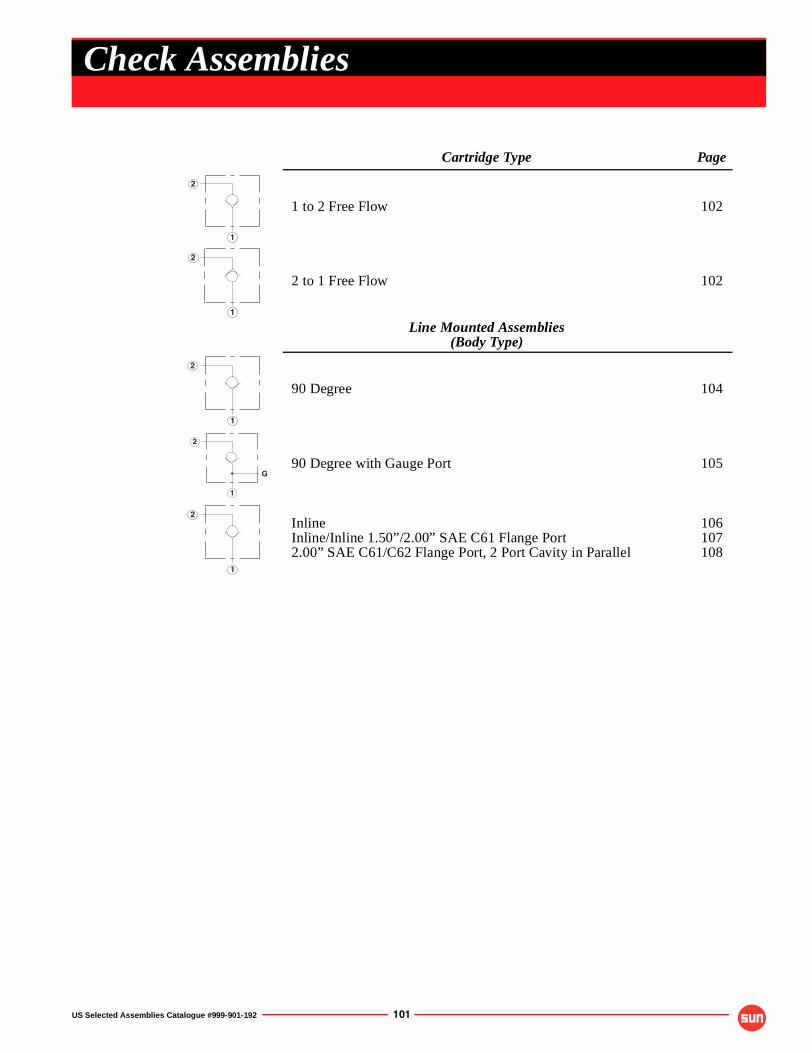
US Selected Assemblies Catalogue #999-901-192 101
Cartridge Type Page
1 to 2 Free Flow 102
2 to 1 Free Flow 102
Line Mounted Assemblies(Body Type)
90 Degree 104
90 Degree with Gauge Port 105
InlineInline/Inline 1.50”/2.00” SAE C61 Flange Port2.00” SAE C61/C62 Flange Port, 2 Port Cavity in Parallel
106107108
1
2
1
2
1
2
G
1
2
1
2
Check Assemblies
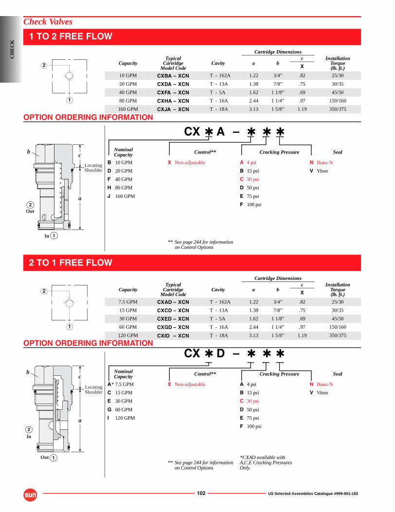
OPTION ORDERING INFORMATION
OPTION ORDERING INFORMATION
102 US Selected Assemblies Catalogue #999-901-192
Check Valves
1 TO 2 FREE FLOW
CX ✱ A – ✱ ✱ ✱
Nominal Control** Cracking Pressure SealCapacity
B 10 GPM X Non-adjustable A 4 psi N Buna-N
D 20 GPM B 15 psi V Viton
F 40 GPM C 30 psi
H 80 GPM D 50 psi
J 160 GPM E 75 psi
F 100 psi
** See page 244 for informationon Control Options
2 TO 1 FREE FLOW
CX ✱ D – ✱ ✱ ✱
Nominal Control** Cracking Pressure SealCapacity
A* 7.5 GPM X Non-adjustable A 4 psi N Buna-N
C 15 GPM B 15 psi V Viton
E 30 GPM C 30 psi
G 60 GPM D 50 psi
I 120 GPM E 75 psi
F 100 psi
*CXAD available with** See page 244 for information A,C,E Cracking Pressures
on Control Options Only.
Cartridge Dimensions
CapacityTypical
CartridgeModel Code
Cavity a bc Installation
Torque(lb. ft.)X
10 GPM CXBA – XCN T - 162A 1.22 3/4” .82 25/30
20 GPM CXDA – XCN T - 13A 1.38 7/8” .75 30/35
40 GPM CXFA – XCN T - 5A 1.62 1 1/8” .69 45/50
80 GPM CXHA – XCN T - 16A 2.44 1 1/4” .97 150/160
160 GPM CXJA – XCN T - 18A 3.13 1 5/8” 1.19 350/375
Cartridge Dimensions
CapacityTypical
CartridgeModel Code
Cavity a bc Installation
Torque(lb. ft.)X
7.5 GPM CXAD – XCN T - 162A 1.22 3/4” .82 25/30
15 GPM CXCD – XCN T - 13A 1.38 7/8” .75 30/35
30 GPM CXED – XCN T - 5A 1.62 1 1/8” .69 45/50
60 GPM CXGD – XCN T - 16A 2.44 1 1/4” .97 150/160
120 GPM CXID – XCN T - 18A 3.13 1 5/8” 1.19 350/375
1
2
c
a
1
2Out
In
LocatingShoulder
b
1
2
c
a
1
2
Out
In
LocatingShoulder
b
CH
EC
K
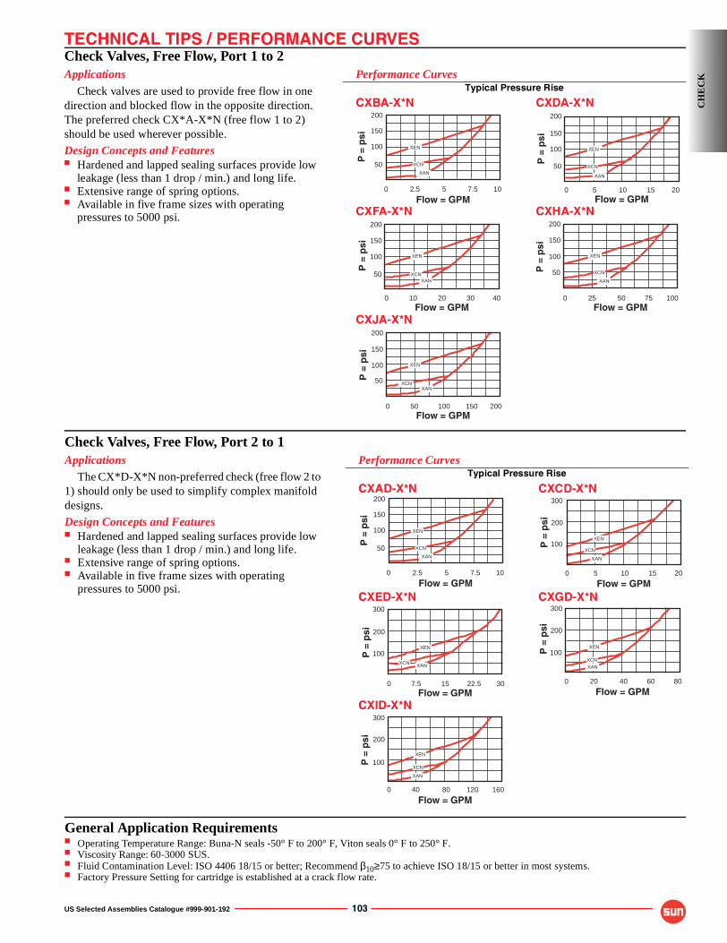
TECHNICAL TIPS / PERFORMANCE CURVES
US Selected Assemblies Catalogue #999-901-192 103
Check Valves, Free Flow, Port 1 to 2Applications
Check valves are used to provide free flow in one direction and blocked flow in the opposite direction. The preferred check CX*A-X*N (free flow 1 to 2) should be used wherever possible.
Design Concepts and Features■ Hardened and lapped sealing surfaces provide low
leakage (less than 1 drop / min.) and long life.■ Extensive range of spring options.■ Available in five frame sizes with operating
pressures to 5000 psi.
Performance CurvesTypical Pressure Rise
CXBA-X*N CXDA-X*N
CXFA-X*N CXHA-X*N
CXJA-X*N200
150
100
0 200 50 100 150
50
Flow = GPM
P =
psi
XCN
XEN
XAN
200
150
100
0 4010 20 30
50
Flow = GPM
P =
psi
XEN
XANXCN
200
150
100
0 100 25 50 75
50
Flow = GPM
P =
psi
XEN
XAN
XCN
200
150
0 102.5 5 7.5
Flow = GPM
P =
psi
100
50 XCN
XEN
XAN
200
150
100
0 205 10 15
50
Flow = GPM
P =
psi
XEN
XAN
XCN
CH
EC
K
Check Valves, Free Flow, Port 2 to 1Applications
The CX*D-X*N non-preferred check (free flow 2 to 1) should only be used to simplify complex manifold designs.
Design Concepts and Features■ Hardened and lapped sealing surfaces provide low
leakage (less than 1 drop / min.) and long life.■ Extensive range of spring options.■ Available in five frame sizes with operating
pressures to 5000 psi.
Performance CurvesTypical Pressure Rise
CXAD-X*N CXCD-X*N
CXED-X*N CXGD-X*N
CXID-X*N300
200
100
0 160 40 80 120
Flow = GPM
P =
psi
XEN
XAN
XCN
300
200
100
0 30 7.5 22.5Flow = GPM
P =
psi
XEN
XCN XAN
15
300
200
100
0 80 20 40 60
Flow = GPM
P =
psi
XEN
XANXCN
200
150
0 102.5 5 7.5
Flow = GPM
P =
psi
100
50 XCN
XEN
XAN
300
200
100
0 20 5 10 15
Flow = GPM
P =
psi
XEN
XAN
XCN
General Application Requirements■ Operating Temperature Range: Buna-N seals -50° F to 200° F, Viton seals 0° F to 250° F.■ Viscosity Range: 60-3000 SUS.■ Fluid Contamination Level: ISO 4406 18/15 or better; Recommend β10≥75 to achieve ISO 18/15 or better in most systems.■ Factory Pressure Setting for cartridge is established at a crack flow rate.
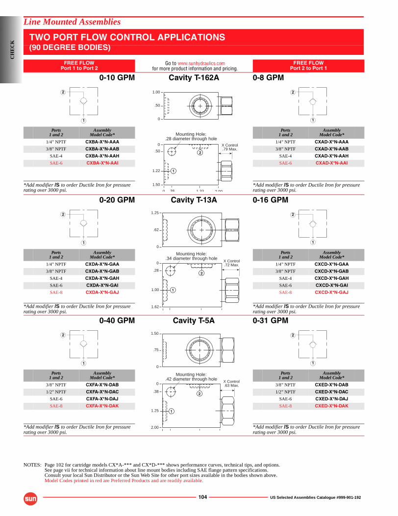
104 US Selected Assemblies Catalogue #999-901-192
Line Mounted Assemblies
TWO PORT FLOW CONTROL APPLICATIONS(90 DEGREE BODIES)
FREE FLOWPort 1 to Port 2
Go to www.sunhydraulics.comfor more product information and pricing.
FREE FLOWPort 2 to Port 1
0-10 GPM Cavity T-162A 0-8 GPM
Ports1 and 2
AssemblyModel Code*
Ports1 and 2
AssemblyModel Code*
1/4” NPTF CXBA-X*N-AAA 1/4” NPTF CXAD-X*N-AAA
3/8” NPTF CXBA-X*N-AAB 3/8” NPTF CXAD-X*N-AAB
SAE-4 CXBA-X*N-AAH SAE-4 CXAD-X*N-AAH
SAE-6 CXBA-X*N-AAI SAE-6 CXAD-X*N-AAI
*Add modifier /S to order Ductile Iron for pressure rating over 3000 psi.
*Add modifier /S to order Ductile Iron for pressure rating over 3000 psi.
0-20 GPM Cavity T-13A 0-16 GPM
Ports1 and 2
AssemblyModel Code*
Ports1 and 2
AssemblyModel Code*
1/4” NPTF CXDA-X*N-GAA 1/4” NPTF CXCD-X*N-GAA
3/8” NPTF CXDA-X*N-GAB 3/8” NPTF CXCD-X*N-GAB
SAE-4 CXDA-X*N-GAH SAE-4 CXCD-X*N-GAH
SAE-6 CXDA-X*N-GAI SAE-6 CXCD-X*N-GAI
SAE-8 CXDA-X*N-GAJ SAE-8 CXCD-X*N-GAJ
*Add modifier /S to order Ductile Iron for pressure rating over 3000 psi.
*Add modifier /S to order Ductile Iron for pressure rating over 3000 psi.
0-40 GPM Cavity T-5A 0-31 GPM
Ports1 and 2
AssemblyModel Code*
Ports1 and 2
AssemblyModel Code*
3/8” NPTF CXFA-X*N-DAB 3/8” NPTF CXED-X*N-DAB
1/2” NPTF CXFA-X*N-DAC 1/2” NPTF CXED-X*N-DAC
SAE-6 CXFA-X*N-DAJ SAE-6 CXED-X*N-DAJ
SAE-8 CXFA-X*N-DAK SAE-8 CXED-X*N-DAK
*Add modifier /S to order Ductile Iron for pressure rating over 3000 psi.
*Add modifier /S to order Ductile Iron for pressure rating over 3000 psi.
NOTES: Page 102 for cartridge models CX*A-*** and CX*D-*** shows performance curves, technical tips, and options.See page vii for technical information about line mount bodies including SAE flange pattern specifications.Consult your local Sun Distributor or the Sun Web Site for other port sizes available in the bodies shown above.Model Codes printed in red are Preferred Products and are readily available.
1
2 1.00
.50
0
X Control.79 Max.
Mounting Hole:.28 diameter through hole
0
0
.50
1.22
1.50
2 001 3328
1
2
1
2
1
2
X Control.72 Max.
Mounting Hole:.34 diameter through hole
0
.28
1.00
1.62
1.25
.62
0
1
2
1
2
1
2
X Control.63 Max.
Mounting Hole:.42 diameter through hole
0
.38
1.25
2.00
1.50
.75
0
1
2
1
2
CH
EC
K
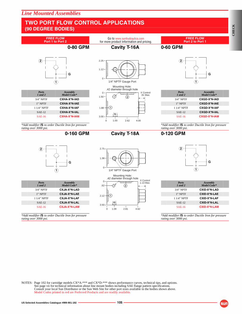
US Selected Assemblies Catalogue #999-901-192 105
Line Mounted Assemblies
TWO PORT FLOW CONTROL APPLICATIONS(90 DEGREE BODIES)
FREE FLOWPort 1 to Port 2
Go to www.sunhydraulics.comfor more product information and pricing.
FREE FLOWPort 2 to Port 1
0-80 GPM Cavity T-16A 0-60 GPM
Ports1 and 2
AssemblyModel Code*
Ports1 and 2
AssemblyModel Code*
3/4” NPTF CXHA-X*N-IAD 3/4” NPTF CXGD-X*N-IAD
1” NPTF CXHA-X*N-IAE 1” NPTF CXGD-X*N-IAE
1 1/4” NPTF CXHA-X*N-IAF 1 1/4” NPTF CXGD-X*N-IAF
SAE-12 CXHA-X*N-IAL SAE-12 CXGD-X*N-IAL
SAE-16 CXHA-X*N-IAM SAE-16 CXGD-X*N-IAM
*Add modifier /S to order Ductile Iron for pressure rating over 3000 psi.
*Add modifier /S to order Ductile Iron for pressure rating over 3000 psi.
0-160 GPM Cavity T-18A 0-120 GPM
Ports1 and 2
AssemblyModel Code*
Ports1 and 2
AssemblyModel Code*
3/4” NPTF CXJA-X*N-LAD 3/4” NPTF CXID-X*N-LAD
1” NPTF CXJA-X*N-LAE 1” NPTF CXID-X*N-LAE
1 1/4” NPTF CXJA-X*N-LAF 1 1/4” NPTF CXID-X*N-LAF
SAE-12 CXJA-X*N-LAL SAE-12 CXID-X*N-LAL
SAE-16 CXJA-X*N-LAM SAE-16 CXID-X*N-LAM
*Add modifier /S to order Ductile Iron for pressure rating over 3000 psi.
*Add modifier /S to order Ductile Iron for pressure rating over 3000 psi.
NOTES: Page 102 for cartridge models CX*A-*** and CX*D-*** shows performance curves, technical tips, and options.See page vii for technical information about line mount bodies including SAE flange pattern specifications.Consult your local Sun Distributor or the Sun Web Site for other port sizes available in the bodies shown above.Model Codes printed in red are Preferred Products and are readily available.
G
1
2
X Control.91 Max.
Mounting Hole:.42 diameter through hole
0
2.25
1.12
1.50
1.88
3.00
4.002.621.00
1/4” NPTF Gauge Port
0
0
G
1
2
1
2
G
G
1
2 2.75
0
1.38
1/4” NPTF Gauge Port
Mounting Hole:.42 diameter through hole
3.50
.62
0
2.12
0 2.81 4.621.09
X Control1.13 Max.
G
1
2
1
2
G
CH
EC
K
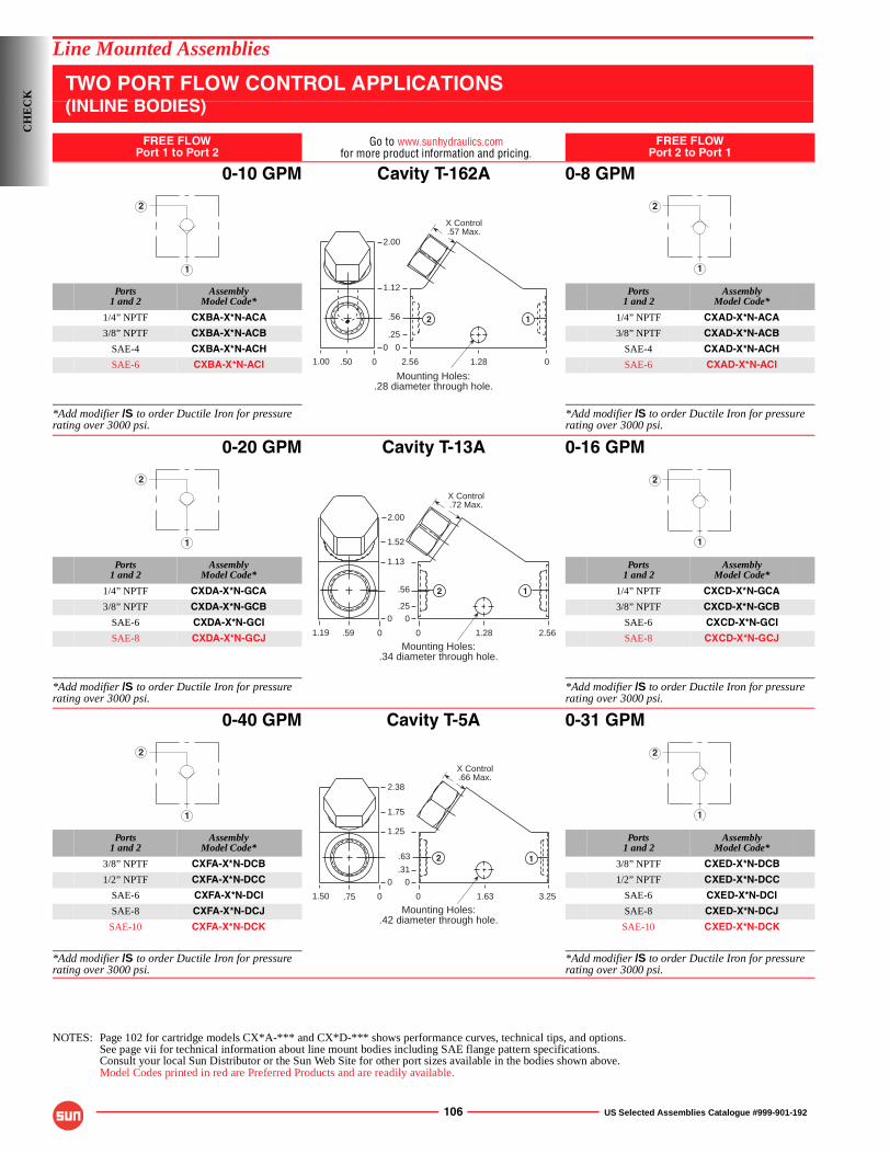
106 US Selected Assemblies Catalogue #999-901-192
Line Mounted Assemblies
TWO PORT FLOW CONTROL APPLICATIONS(INLINE BODIES)
FREE FLOWPort 1 to Port 2
Go to www.sunhydraulics.comfor more product information and pricing.
FREE FLOWPort 2 to Port 1
0-10 GPM Cavity T-162A 0-8 GPM
Ports1 and 2
AssemblyModel Code*
Ports1 and 2
AssemblyModel Code*
1/4” NPTF CXBA-X*N-ACA 1/4” NPTF CXAD-X*N-ACA
3/8” NPTF CXBA-X*N-ACB 3/8” NPTF CXAD-X*N-ACB
SAE-4 CXBA-X*N-ACH SAE-4 CXAD-X*N-ACH
SAE-6 CXBA-X*N-ACI SAE-6 CXAD-X*N-ACI
*Add modifier /S to order Ductile Iron for pressure rating over 3000 psi.
*Add modifier /S to order Ductile Iron for pressure rating over 3000 psi.
0-20 GPM Cavity T-13A 0-16 GPM
Ports1 and 2
AssemblyModel Code*
Ports1 and 2
AssemblyModel Code*
1/4” NPTF CXDA-X*N-GCA 1/4” NPTF CXCD-X*N-GCA
3/8” NPTF CXDA-X*N-GCB 3/8” NPTF CXCD-X*N-GCB
SAE-6 CXDA-X*N-GCI SAE-6 CXCD-X*N-GCI
SAE-8 CXDA-X*N-GCJ SAE-8 CXCD-X*N-GCJ
*Add modifier /S to order Ductile Iron for pressure rating over 3000 psi.
*Add modifier /S to order Ductile Iron for pressure rating over 3000 psi.
0-40 GPM Cavity T-5A 0-31 GPM
Ports1 and 2
AssemblyModel Code*
Ports1 and 2
AssemblyModel Code*
3/8” NPTF CXFA-X*N-DCB 3/8” NPTF CXED-X*N-DCB
1/2” NPTF CXFA-X*N-DCC 1/2” NPTF CXED-X*N-DCC
SAE-6 CXFA-X*N-DCI SAE-6 CXED-X*N-DCI
SAE-8 CXFA-X*N-DCJ SAE-8 CXED-X*N-DCJ
SAE-10 CXFA-X*N-DCK SAE-10 CXED-X*N-DCK
*Add modifier /S to order Ductile Iron for pressure rating over 3000 psi.
*Add modifier /S to order Ductile Iron for pressure rating over 3000 psi.
NOTES: Page 102 for cartridge models CX*A-*** and CX*D-*** shows performance curves, technical tips, and options.See page vii for technical information about line mount bodies including SAE flange pattern specifications.Consult your local Sun Distributor or the Sun Web Site for other port sizes available in the bodies shown above.Model Codes printed in red are Preferred Products and are readily available.
1
2
Mounting Holes:.28 diameter through hole.
2.56
1.12
.56
0
01.28
12
.25
.501.00
2.00
0
0
X Control.57 Max.
1
2
1
2
Mounting Holes:.34 diameter through hole.
0
1.52
1.13
.56
0
2.561.28
12
.25
.591.19
2.00
0
0
X Control.72 Max.
1
2
1
2
Mounting Holes:.42 diameter through hole.
0
1.75
1.25
.63
0
3.251.63
12.31
.751.50
2.38
0
0
X Control.66 Max.
1
2
CH
EC
K
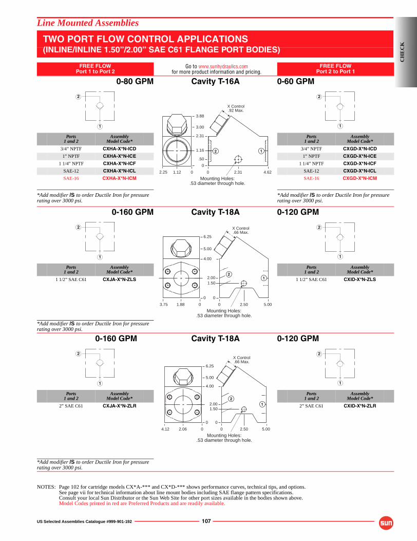
US Selected Assemblies Catalogue #999-901-192 107
Line Mounted Assemblies
TWO PORT FLOW CONTROL APPLICATIONS(INLINE/INLINE 1.50”/2.00” SAE C61 FLANGE PORT BODIES)
FREE FLOWPort 1 to Port 2
Go to www.sunhydraulics.comfor more product information and pricing.
FREE FLOWPort 2 to Port 1
0-80 GPM Cavity T-16A 0-60 GPM
Ports1 and 2
AssemblyModel Code*
Ports1 and 2
AssemblyModel Code*
3/4” NPTF CXHA-X*N-ICD 3/4” NPTF CXGD-X*N-ICD
1” NPTF CXHA-X*N-ICE 1” NPTF CXGD-X*N-ICE
1 1/4” NPTF CXHA-X*N-ICF 1 1/4” NPTF CXGD-X*N-ICF
SAE-12 CXHA-X*N-ICL SAE-12 CXGD-X*N-ICL
SAE-16 CXHA-X*N-ICM SAE-16 CXGD-X*N-ICM
*Add modifier /S to order Ductile Iron for pressure rating over 3000 psi.
*Add modifier /S to order Ductile Iron for pressure rating over 3000 psi.
0-160 GPM Cavity T-18A 0-120 GPM
Ports1 and 2
AssemblyModel Code*
Ports1 and 2
AssemblyModel Code*
1 1/2” SAE C61 CXJA-X*N-ZLS 1 1/2” SAE C61 CXID-X*N-ZLS
*Add modifier /S to order Ductile Iron for pressure rating over 3000 psi.
0-160 GPM Cavity T-18A 0-120 GPM
Ports1 and 2
AssemblyModel Code*
Ports1 and 2
AssemblyModel Code*
2” SAE C61 CXJA-X*N-ZLR 2” SAE C61 CXID-X*N-ZLR
*Add modifier /S to order Ductile Iron for pressure rating over 3000 psi.
NOTES: Page 102 for cartridge models CX*A-*** and CX*D-*** shows performance curves, technical tips, and options.See page vii for technical information about line mount bodies including SAE flange pattern specifications.Consult your local Sun Distributor or the Sun Web Site for other port sizes available in the bodies shown above.Model Codes printed in red are Preferred Products and are readily available.
1
2
Mounting Holes:.53 diameter through hole.
0
3.00
2.31
1.16
4.622.31
12
.50
1.122.25
3.88
0
0
X Control.92 Max.
1
2
1
2
Mounting Holes:.53 diameter through hole.
0
5.00
4.00
2.00
0
5.002.50
12
1.50
1.883.75
6.25
0
0
X Control.66 Max.
1
2
1
2
Mounting Holes:.53 diameter through hole.
0
5.00
4.00
2.00
0
5.002.50
12
1.50
2.064.12
6.25
0
0
X Control.66 Max.
1
2
CH
EC
K
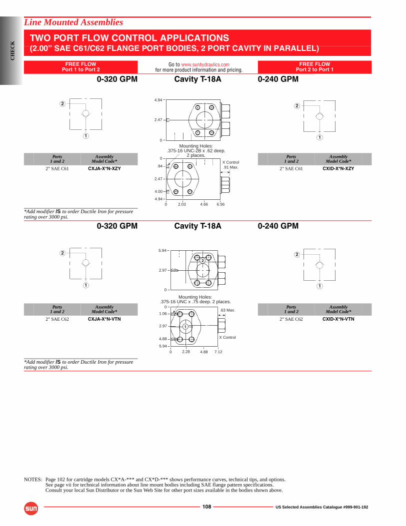
108 US Selected Assemblies Catalogue #999-901-192
Line Mounted Assemblies
TWO PORT FLOW CONTROL APPLICATIONS(2.00” SAE C61/C62 FLANGE PORT BODIES, 2 PORT CAVITY IN PARALLEL)
FREE FLOWPort 1 to Port 2
Go to www.sunhydraulics.comfor more product information and pricing.
FREE FLOWPort 2 to Port 1
0-320 GPM Cavity T-18A 0-240 GPM
Ports1 and 2
AssemblyModel Code*
Ports1 and 2
AssemblyModel Code*
2” SAE C61 CXJA-X*N-XZY 2” SAE C61 CXID-X*N-XZY
*Add modifier /S to order Ductile Iron for pressure rating over 3000 psi.
0-320 GPM Cavity T-18A 0-240 GPM
Ports1 and 2
AssemblyModel Code*
Ports1 and 2
AssemblyModel Code*
2” SAE C62 CXJA-X*N-VTN 2” SAE C62 CXID-X*N-VTN
*Add modifier /S to order Ductile Iron for pressure rating over 3000 psi.
NOTES: Page 102 for cartridge models CX*A-*** and CX*D-*** shows performance curves, technical tips, and options.See page vii for technical information about line mount bodies including SAE flange pattern specifications.Consult your local Sun Distributor or the Sun Web Site for other port sizes available in the bodies shown above.
1
2
.91 Max.
Mounting Holes:.375-16 UNC-2B x .62 deep.
2 places.0
2.47
.94
4.00
4.940 6.564.662.03
X Control
0
4.94
2.47
1
2
1
2
.63 Max.
X Control
5.94
2.97
0
0
0
1.06
2.97
5.94
7.124.882.28
4.88
Mounting Holes:.375-16 UNC x .75 deep. 2 places.
2
1
1
2
CH
EC
K
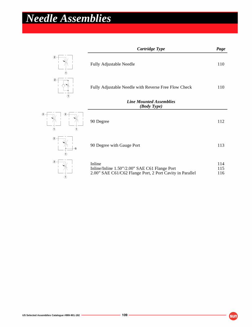
US Selected Assemblies Catalogue #999-901-192 109
Cartridge Type Page
Fully Adjustable Needle 110
Fully Adjustable Needle with Reverse Free Flow Check 110
Line Mounted Assemblies(Body Type)
90 Degree 112
90 Degree with Gauge Port 113
InlineInline/Inline 1.50”/2.00” SAE C61 Flange Port2.00” SAE C61/C62 Flange Port, 2 Port Cavity in Parallel
114115116
1
2
1
2
1
2
1
2
1
2
G
1
2
Needle Assemblies
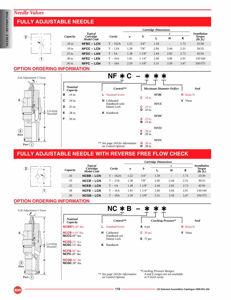
OPTION ORDERING INFORMATION
OPTION ORDERING INFORMATION
110 US Selected Assemblies Catalogue #999-901-192
Needle Valves
FULLY ADJUSTABLE NEEDLE
NF ✱ C – ✱ ✱ ✱
Nominal Control** Maximum Diameter Orifice SealCapacity
B .16 in. L Standard Screw NFBC N Buna-NC .16 in.
C .19 in. H Calibrated V VitonHandknob with NFCC
D .25 in. Detent Lock C .19 in.D .10 in.
E .38 in. K HandknobNFDC
F .56 in. A .25 in.B .13 in.
NFECE .38 in.F .28 in.
NFFC** See page 244 for information G .56 in.
on Control Options H .38 in.
FULLY ADJUSTABLE NEEDLE WITH REVERSE FREE FLOW CHECK
NC ✱ B – ✱ ✱ ✱
Nominal Control** Cracking Pressure* SealCapacity
NCBB*0.16” dia. L Standard Screw A 4 psi N Buna-N
NCCB 0.19” dia. H Calibrated C 30 psi V VitonNCCC.09” dia. Handknob wit
Detent Lock E 75 psiNCEB.25” dia.NCEC.13” dia. K Handknob
NCFB.38” dia.NCFC.28” dia.
NCGB.56” dia.NCGC.38” dia.
*Cracking Pressure Ranges:** See page 244 for information A and E ranges are not available
on Control Options in T-162A cavity
Cartridge Dimensions
CapacityTypical
CartridgeModel Code
Cavity a bc Installation
Torque(lb. ft.)L H K
.16 in NFBC – LCN T - 162A 1.22 3/4” 1.59 - 1.73 25/30
.19 in NFCC – LCN T - 13A 1.38 7/8” 2.06 2.44 2.31 30/35
.25 in. NFDC – LAN T - 5A 1.38 1 1/8” 2.44 2.82 2.73 45/50
.38 in. NFEC – LEN T - 16A 1.81 1 1/4” 2.66 3.06 2.91 150/160
.56 in. NFFC – LGN T - 18A 2.50 1 5/8” 3.31 3.50 3.47 350/375
Cartridge Dimensions
Capacity
TypicalCartridge
Model CodeCavity a b
c InstallationTorque(lb. ft.)L H K
.16 NCBB – LCN T - 162A 1.22 3/4” 1.59 - 1.73 25/30
.19 NCCB – LCN T - 13A 1.38 7/8” 2.06 2.44 2.31 30/35
.25 NCEB – LCN T - 5A 1.38 1 1/8” 2.44 2.82 2.73 45/50
.38 NCFB – LCN T - 16A 1.81 1 1/4” 2.66 3.06 2.91 150/160
.56 NCGB – LCN T - 18A 2.50 1 5/8” 3.31 3.50 3.47 350/375
1
2
- +
Full Adjustment 5 Turns
c
a
1
2
Port
LocatingShoulder
Port
b
1
2
-+
Full Adjustment 5 Turns
1
c
a2
Port
LocatingShoulder
Port
b
NE
ED
LE
/ R
EST
RIC
TO
R
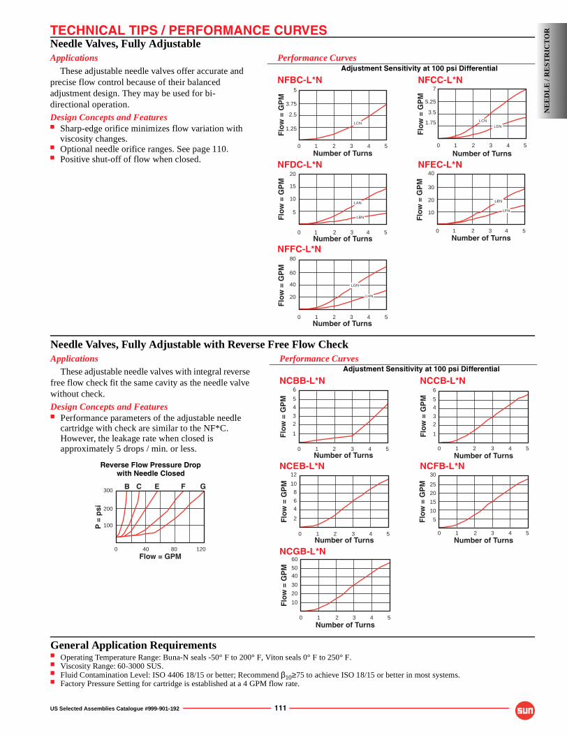
TECHNICAL TIPS / PERFORMANCE CURVES
US Selected Assemblies Catalogue #999-901-192 111
Needle Valves, Fully AdjustableApplications
These adjustable needle valves offer accurate and precise flow control because of their balanced adjustment design. They may be used for bi-directional operation.
Design Concepts and Features■ Sharp-edge orifice minimizes flow variation with
viscosity changes.■ Optional needle orifice ranges. See page 110.■ Positive shut-off of flow when closed.
Performance CurvesAdjustment Sensitivity at 100 psi Differential
NFBC-L*N NFCC-L*N
NFDC-L*N NFEC-L*N
NFFC-L*N
LGN
LHN
80
60
0 51 2 3
20
Number of Turns
Flo
w =
GP
M
4
40
LAN
LBN
20
15
0 51 2 3
5
Number of Turns
Flo
w =
GP
M
4
10 LEN
LFN
40
30
0 51 2 3
10
Number of Turns
Flo
w =
GP
M
4
20
LCN
5
3.75
0 54 1 2 3
1.25
Number of Turns
Flo
w =
GP
M
2.5LCN
LDN
7
1.75
0 51 2 3
Number of Turns
Flo
w =
GP
M
4
5.25
3.5 NE
ED
LE
/ R
EST
RIC
TO
R
Needle Valves, Fully Adjustable with Reverse Free Flow CheckApplications
These adjustable needle valves with integral reverse free flow check fit the same cavity as the needle valve without check.
Design Concepts and Features■ Performance parameters of the adjustable needle
cartridge with check are similar to the NF*C. However, the leakage rate when closed is approximately 5 drops / min. or less.
12
10
8
0 54 1 2 3
6
Number of Turns
Flo
w =
GP
M
4
2
60
40
0 54 1 2 3Number of Turns
Flo
w =
GP
M
20
30
50
10
Performance CurvesAdjustment Sensitivity at 100 psi Differential
NCBB-L*N NCCB-L*N
NCEB-L*N NCFB-L*N
NCGB-L*N
6
5
4
0 54 1 2 3
3
Number of Turns
Flo
w =
GP
M
2
1
30
20
0 54 1 2 3Number of Turns
Flo
w =
GP
M
10
25
15
5
6
5
4
0 54 1 2 3
3
Number of Turns
Flo
w =
GP
M2
1
B300
200
100
0 12040 80Flow = GPM
P =
psi
EC GF
Reverse Flow Pressure Dropwith Needle Closed
General Application Requirements■ Operating Temperature Range: Buna-N seals -50° F to 200° F, Viton seals 0° F to 250° F.■ Viscosity Range: 60-3000 SUS.■ Fluid Contamination Level: ISO 4406 18/15 or better; Recommend β10≥75 to achieve ISO 18/15 or better in most systems.■ Factory Pressure Setting for cartridge is established at a 4 GPM flow rate.
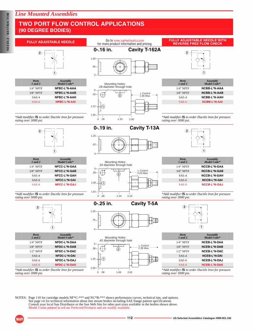
112 US Selected Assemblies Catalogue #999-901-192
Line Mounted Assemblies
TWO PORT FLOW CONTROL APPLICATIONS(90 DEGREE BODIES)
FULLY ADJUSTABLE NEEDLE Go to www.sunhydraulics.comfor more product information and pricing.
FULLY ADJUSTABLE NEEDLE WITHREVERSE FREE FLOW CHECK
0-.16 in. Cavity T-162A
Ports1 and 2
AssemblyModel Code*
Ports1 and 2
AssemblyModel Code*
1/4” NPTF NFBC-L*N-AAA 1/4” NPTF NCBB-L*N-AAA
3/8” NPTF NFBC-L*N-AAB 3/8” NPTF NCBB-L*N-AAB
SAE-4 NFBC-L*N-AAH SAE-4 NCBB-L*N-AAH
SAE-6 NFBC-L*N-AAI SAE-6 NCBB-L*N-AAI
*Add modifier /S to order Ductile Iron for pressure rating over 3000 psi.
*Add modifier /S to order Ductile Iron for pressure rating over 3000 psi.
0-.19 in. Cavity T-13A
Ports1 and 2
AssemblyModel Code*
Ports1 and 2
AssemblyModel Code*
1/4” NPTF NFCC-L*N-GAA 1/4” NPTF NCCB-L*N-GAA
3/8” NPTF NFCC-L*N-GAB 3/8” NPTF NCCB-L*N-GAB
SAE-4 NFCC-L*N-GAH SAE-4 NCCB-L*N-GAH
SAE-6 NFCC-L*N-GAI SAE-6 NCCB-L*N-GAI
SAE-8 NFCC-L*N-GAJ SAE-8 NCCB-L*N-GAJ
*Add modifier /S to order Ductile Iron for pressure rating over 3000 psi.
*Add modifier /S to order Ductile Iron for pressure rating over 3000 psi.
0-.25 in. Cavity T-5A
Ports1 and 2
AssemblyModel Code*
Ports1 and 2
AssemblyModel Code*
1/4” NPTF NFDC-L*N-DAA 1/4” NPTF NCEB-L*N-DAA
3/8” NPTF NFDC-L*N-DAB 3/8” NPTF NCEB-L*N-DAB
1/2” NPTF NFDC-L*N-DAC 1/2” NPTF NCEB-L*N-DAC
SAE-4 NFDC-L*N-DAI SAE-4 NCEB-L*N-DAI
SAE-6 NFDC-L*N-DAJ SAE-6 NCEB-L*N-DAJ
SAE-8 NFDC-L*N-DAK SAE-8 NCEB-L*N-DAK
*Add modifier /S to order Ductile Iron for pressure rating over 3000 psi.
*Add modifier /S to order Ductile Iron for pressure rating over 3000 psi.
NOTES: Page 110 for cartridge models NF*C-*** and NC*B-*** shows performance curves, technical tips, and options.See page vii for technical information about line mount bodies including SAE flange pattern specifications.Consult your local Sun Distributor or the Sun Web Site for other port sizes available in the bodies shown above.Model Codes printed in red are Preferred Products and are readily available.
1
2
1
2
1.00
.50
0
Mounting Holes:.28 diameter through hole
0
0
.50
1.22
1.50
2.001.33.28
L Control1.56 Max.
1
2
1
2
1
2
Mounting Holes:.34 diameter through hole
0
0
.28
1.00
1.62
2.191.44
1.25
.62
0
.28
L Control2.03 Max.
1
2
1
2
1
2
Mounting Holes:.42 diameter through hole
0
0
.38
1.25
2.00
2.621.69
1.50
.75
0
.38
L Control2.38 Max.
1
2
NE
ED
LE
/ R
EST
RIC
TO
R
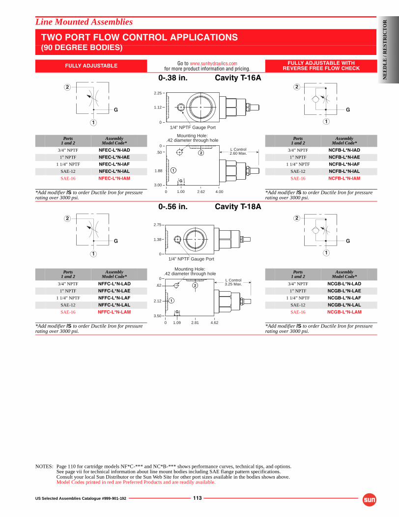
US Selected Assemblies Catalogue #999-901-192 113
Line Mounted Assemblies
TWO PORT FLOW CONTROL APPLICATIONS(90 DEGREE BODIES)
FULLY ADJUSTABLE Go to www.sunhydraulics.comfor more product information and pricing.
FULLY ADJUSTABLE WITHREVERSE FREE FLOW CHECK
0-.38 in. Cavity T-16A
Ports1 and 2
AssemblyModel Code*
Ports1 and 2
AssemblyModel Code*
3/4” NPTF NFEC-L*N-IAD 3/4” NPTF NCFB-L*N-IAD
1” NPTF NFEC-L*N-IAE 1” NPTF NCFB-L*N-IAE
1 1/4” NPTF NFEC-L*N-IAF 1 1/4” NPTF NCFB-L*N-IAF
SAE-12 NFEC-L*N-IAL SAE-12 NCFB-L*N-IAL
SAE-16 NFEC-L*N-IAM SAE-16 NCFB-L*N-IAM
*Add modifier /S to order Ductile Iron for pressure rating over 3000 psi.
*Add modifier /S to order Ductile Iron for pressure rating over 3000 psi.
0-.56 in. Cavity T-18A
Ports1 and 2
AssemblyModel Code*
Ports1 and 2
AssemblyModel Code*
3/4” NPTF NFFC-L*N-LAD 3/4” NPTF NCGB-L*N-LAD
1” NPTF NFFC-L*N-LAE 1” NPTF NCGB-L*N-LAE
1 1/4” NPTF NFFC-L*N-LAF 1 1/4” NPTF NCGB-L*N-LAF
SAE-12 NFFC-L*N-LAL SAE-12 NCGB-L*N-LAL
SAE-16 NFFC-L*N-LAM SAE-16 NCGB-L*N-LAM
*Add modifier /S to order Ductile Iron for pressure rating over 3000 psi.
*Add modifier /S to order Ductile Iron for pressure rating over 3000 psi.
NOTES: Page 110 for cartridge models NF*C-*** and NC*B-*** shows performance curves, technical tips, and options.See page vii for technical information about line mount bodies including SAE flange pattern specifications.Consult your local Sun Distributor or the Sun Web Site for other port sizes available in the bodies shown above.Model Codes printed in red are Preferred Products and are readily available.
1
2
G
1
2
G
Mounting Hole:.42 diameter through hole
0
2.25
1.12
.50
1.88
3.00G
1
4.002.621.00
1/4” NPTF Gauge Port
0
0
L Control2.60 Max.
G
1
2
1
2
G
1
2
G
2.75
0
1.38
1/4” NPTF Gauge Port
Mounting Hole:.42 diameter through hole
3.50
.62
0
2.12
0 2.81 4.621.09
L Control3.25 Max.
1
G
2
NE
ED
LE
/ R
EST
RIC
TO
R
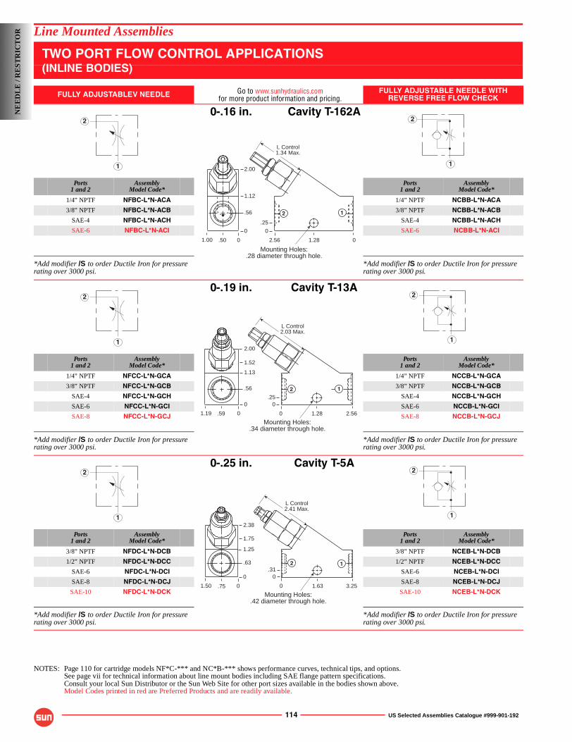
114 US Selected Assemblies Catalogue #999-901-192
Line Mounted Assemblies
TWO PORT FLOW CONTROL APPLICATIONS(INLINE BODIES)
FULLY ADJUSTABLEV NEEDLE Go to www.sunhydraulics.comfor more product information and pricing.
FULLY ADJUSTABLE NEEDLE WITHREVERSE FREE FLOW CHECK
0-.16 in. Cavity T-162A
Ports1 and 2
AssemblyModel Code*
Ports1 and 2
AssemblyModel Code*
1/4” NPTF NFBC-L*N-ACA 1/4” NPTF NCBB-L*N-ACA
3/8” NPTF NFBC-L*N-ACB 3/8” NPTF NCBB-L*N-ACB
SAE-4 NFBC-L*N-ACH SAE-4 NCBB-L*N-ACH
SAE-6 NFBC-L*N-ACI SAE-6 NCBB-L*N-ACI
*Add modifier /S to order Ductile Iron for pressure rating over 3000 psi.
*Add modifier /S to order Ductile Iron for pressure rating over 3000 psi.
0-.19 in. Cavity T-13A
Ports1 and 2
AssemblyModel Code*
Ports1 and 2
AssemblyModel Code*
1/4” NPTF NFCC-L*N-GCA 1/4” NPTF NCCB-L*N-GCA
3/8” NPTF NFCC-L*N-GCB 3/8” NPTF NCCB-L*N-GCB
SAE-4 NFCC-L*N-GCH SAE-4 NCCB-L*N-GCH
SAE-6 NFCC-L*N-GCI SAE-6 NCCB-L*N-GCI
SAE-8 NFCC-L*N-GCJ SAE-8 NCCB-L*N-GCJ
*Add modifier /S to order Ductile Iron for pressure rating over 3000 psi.
*Add modifier /S to order Ductile Iron for pressure rating over 3000 psi.
0-.25 in. Cavity T-5A
Ports1 and 2
AssemblyModel Code*
Ports1 and 2
AssemblyModel Code*
3/8” NPTF NFDC-L*N-DCB 3/8” NPTF NCEB-L*N-DCB
1/2” NPTF NFDC-L*N-DCC 1/2” NPTF NCEB-L*N-DCC
SAE-6 NFDC-L*N-DCI SAE-6 NCEB-L*N-DCI
SAE-8 NFDC-L*N-DCJ SAE-8 NCEB-L*N-DCJ
SAE-10 NFDC-L*N-DCK SAE-10 NCEB-L*N-DCK
*Add modifier /S to order Ductile Iron for pressure rating over 3000 psi.
*Add modifier /S to order Ductile Iron for pressure rating over 3000 psi.
NOTES: Page 110 for cartridge models NF*C-*** and NC*B-*** shows performance curves, technical tips, and options.See page vii for technical information about line mount bodies including SAE flange pattern specifications.Consult your local Sun Distributor or the Sun Web Site for other port sizes available in the bodies shown above.Model Codes printed in red are Preferred Products and are readily available.
1
2
1
2
Mounting Holes:.28 diameter through hole.
2.56
1.12
.56
0
01.28
.25
.501.00
2.00
0
0
L Control1.34 Max.
12
1
2
1
2
Mounting Holes:.34 diameter through hole.
0
1.52
1.13
.56
0
2.561.28
.25
.591.19
2.00
0
0
L Control2.03 Max.
2 1
1
2
1
2
0
1.75
1.25
.63
0
3.251.63
.31
.751.50
2.38
0
0
L Control2.41 Max.
2
Mounting Holes:.42 diameter through hole.
1
NE
ED
LE
/ R
EST
RIC
TO
R
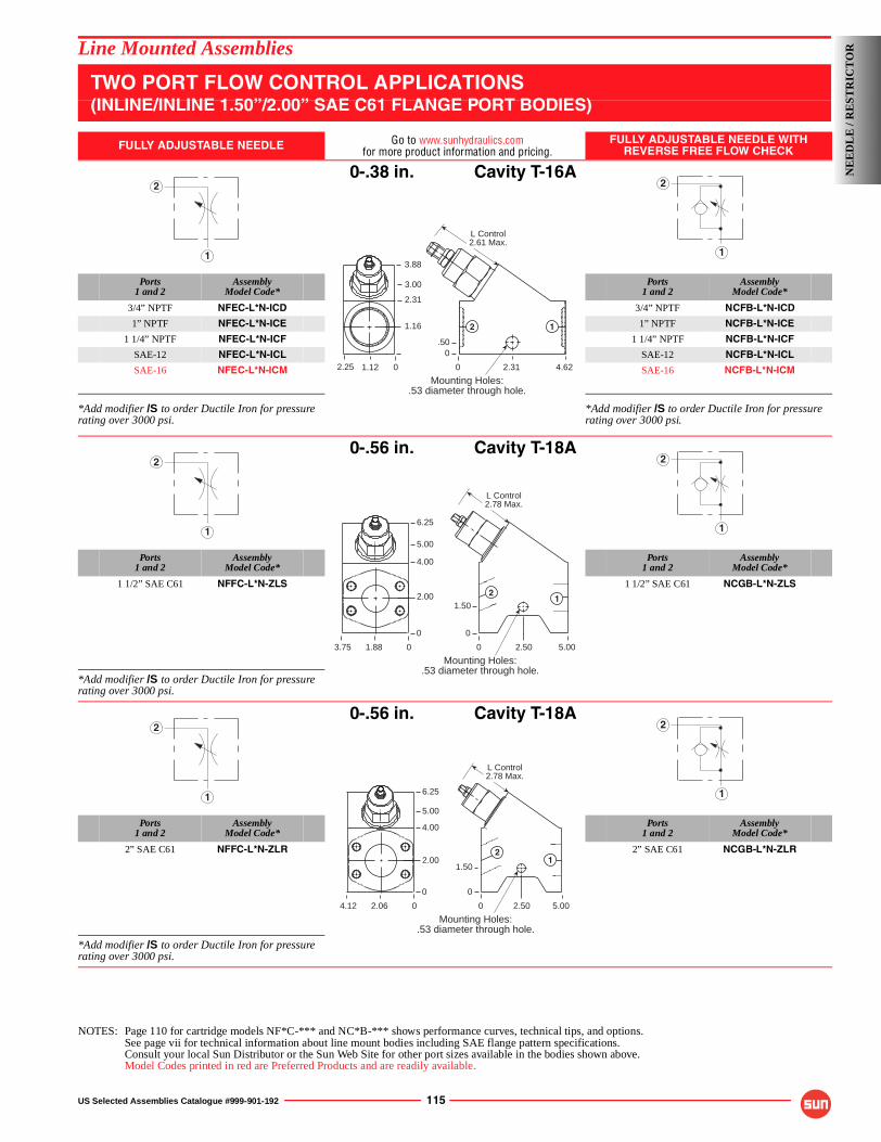
US Selected Assemblies Catalogue #999-901-192 115
Line Mounted Assemblies
TWO PORT FLOW CONTROL APPLICATIONS(INLINE/INLINE 1.50”/2.00” SAE C61 FLANGE PORT BODIES)
FULLY ADJUSTABLE NEEDLE Go to www.sunhydraulics.comfor more product information and pricing.
FULLY ADJUSTABLE NEEDLE WITHREVERSE FREE FLOW CHECK
0-.38 in. Cavity T-16A
Ports1 and 2
AssemblyModel Code*
Ports1 and 2
AssemblyModel Code*
3/4” NPTF NFEC-L*N-ICD 3/4” NPTF NCFB-L*N-ICD
1” NPTF NFEC-L*N-ICE 1” NPTF NCFB-L*N-ICE
1 1/4” NPTF NFEC-L*N-ICF 1 1/4” NPTF NCFB-L*N-ICF
SAE-12 NFEC-L*N-ICL SAE-12 NCFB-L*N-ICL
SAE-16 NFEC-L*N-ICM SAE-16 NCFB-L*N-ICM
*Add modifier /S to order Ductile Iron for pressure rating over 3000 psi.
*Add modifier /S to order Ductile Iron for pressure rating over 3000 psi.
0-.56 in. Cavity T-18A
Ports1 and 2
AssemblyModel Code*
Ports1 and 2
AssemblyModel Code*
1 1/2” SAE C61 NFFC-L*N-ZLS 1 1/2” SAE C61 NCGB-L*N-ZLS
*Add modifier /S to order Ductile Iron for pressure rating over 3000 psi.
0-.56 in. Cavity T-18A
Ports1 and 2
AssemblyModel Code*
Ports1 and 2
AssemblyModel Code*
2” SAE C61 NFFC-L*N-ZLR 2” SAE C61 NCGB-L*N-ZLR
*Add modifier /S to order Ductile Iron for pressure rating over 3000 psi.
NOTES: Page 110 for cartridge models NF*C-*** and NC*B-*** shows performance curves, technical tips, and options.See page vii for technical information about line mount bodies including SAE flange pattern specifications.Consult your local Sun Distributor or the Sun Web Site for other port sizes available in the bodies shown above.Model Codes printed in red are Preferred Products and are readily available.
1
2
1
2
Mounting Holes:.53 diameter through hole.
0
3.00
2.31
1.16
4.622.31
.50
1.122.25
3.88
0
0
L Control2.61 Max.
2 1
1
2
1
2
Mounting Holes:.53 diameter through hole.
0
5.00
4.00
2.00
0
5.002.50
12
1.50
1.883.75
6.25
0
0
L Control2.78 Max.
1
2
1
2
Mounting Holes:.53 diameter through hole.
0
5.00
4.00
2.00
0
5.002.50
12
1.50
2.064.12
6.25
0
0
L Control2.78 Max.
NE
ED
LE
/ R
EST
RIC
TO
R
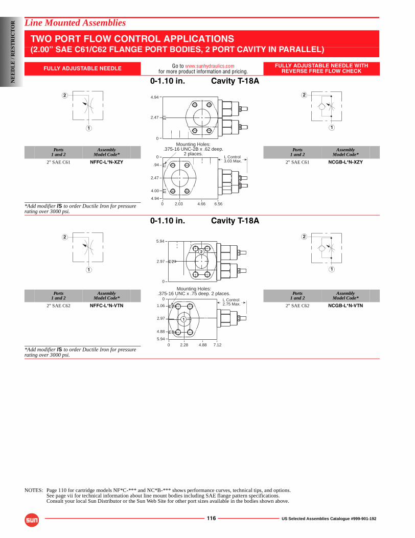
116 US Selected Assemblies Catalogue #999-901-192
Line Mounted Assemblies
TWO PORT FLOW CONTROL APPLICATIONS(2.00” SAE C61/C62 FLANGE PORT BODIES, 2 PORT CAVITY IN PARALLEL)
FULLY ADJUSTABLE NEEDLE Go to www.sunhydraulics.comfor more product information and pricing.
FULLY ADJUSTABLE NEEDLE WITHREVERSE FREE FLOW CHECK
0-1.10 in. Cavity T-18A
Ports1 and 2
AssemblyModel Code*
Ports1 and 2
AssemblyModel Code*
2” SAE C61 NFFC-L*N-XZY 2” SAE C61 NCGB-L*N-XZY
*Add modifier /S to order Ductile Iron for pressure rating over 3000 psi.
0-1.10 in. Cavity T-18A
Ports1 and 2
AssemblyModel Code*
Ports1 and 2
AssemblyModel Code*
2” SAE C62 NFFC-L*N-VTN 2” SAE C62 NCGB-L*N-VTN
*Add modifier /S to order Ductile Iron for pressure rating over 3000 psi.
NOTES: Page 110 for cartridge models NF*C-*** and NC*B-*** shows performance curves, technical tips, and options.See page vii for technical information about line mount bodies including SAE flange pattern specifications.Consult your local Sun Distributor or the Sun Web Site for other port sizes available in the bodies shown above.
1
2
1
2
Mounting Holes:.375-16 UNC-2B x .62 deep.
2 places.0
2.47
.94
4.00
4.940 6.564.662.03
0
4.94
2.47
L Control 3.03 Max.
1
2
1
25.94
2.97
0
0
0
1.06
2.97
5.94
7.124.882.28
4.88
Mounting Holes:.375-16 UNC x .75 deep. 2 places.
L Control 2.75 Max.
2
1
NE
ED
LE
/ R
EST
RIC
TO
R
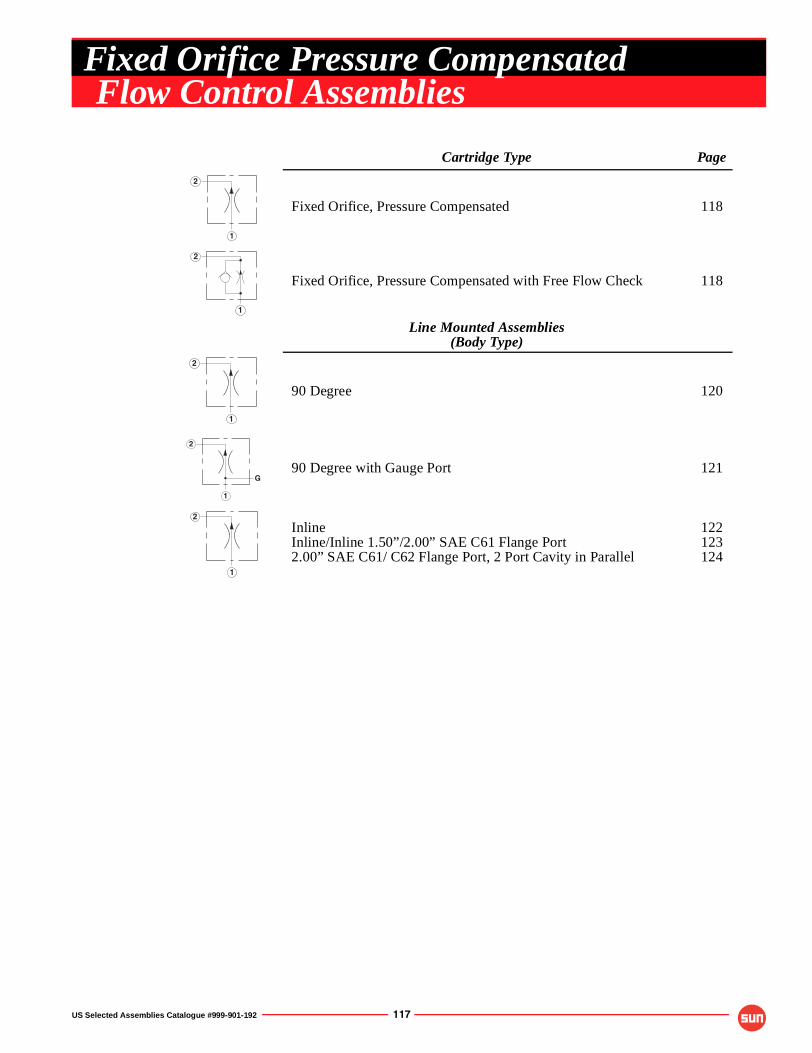
US Selected Assemblies Catalogue #999-901-192 117
Cartridge Type Page
Fixed Orifice, Pressure Compensated 118
Fixed Orifice, Pressure Compensated with Free Flow Check 118
Line Mounted Assemblies(Body Type)
90 Degree 120
90 Degree with Gauge Port 121
InlineInline/Inline 1.50”/2.00” SAE C61 Flange Port2.00” SAE C61/ C62 Flange Port, 2 Port Cavity in Parallel
122123124
1
2
1
2
1
2
1
2
G
1
2
Fixed Orifice Pressure CompensatedFlow Control Assemblies
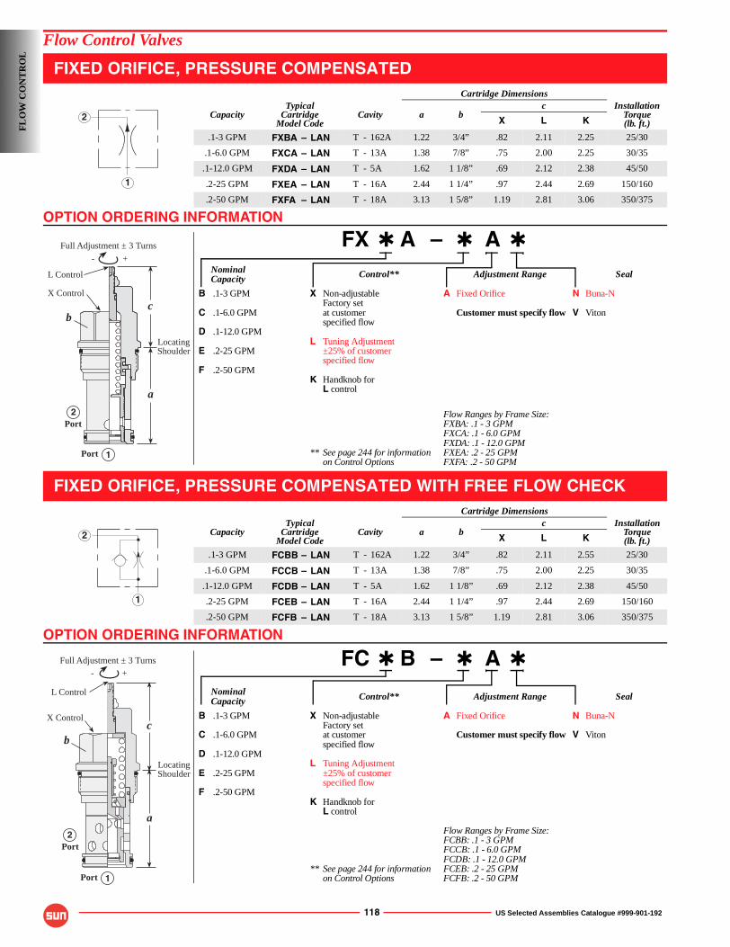
OPTION ORDERING INFORMATION
OPTION ORDERING INFORMATION
118 US Selected Assemblies Catalogue #999-901-192
Flow Control Valves
FIXED ORIFICE, PRESSURE COMPENSATED
FX ✱ A – ✱ A ✱
Nominal Control** Adjustment Range SealCapacity
B .1-3 GPM X Non-adjustable A Fixed Orifice N Buna-NFactory set
C .1-6.0 GPM at customer Customer must specify flow V Vitonspecified flow
D .1-12.0 GPML Tuning Adjustment
E .2-25 GPM ±25% of customerspecified flow
F .2-50 GPMK Handknob for
L control
Flow Ranges by Frame Size:FXBA: .1 - 3 GPMFXCA: .1 - 6.0 GPMFXDA: .1 - 12.0 GPM
** See page 244 for information FXEA: .2 - 25 GPMon Control Options FXFA: .2 - 50 GPM
FIXED ORIFICE, PRESSURE COMPENSATED WITH FREE FLOW CHECK
FC ✱ B – ✱ A ✱
Nominal Control** Adjustment Range SealCapacity
B .1-3 GPM X Non-adjustable A Fixed Orifice N Buna-NFactory set
C .1-6.0 GPM at customer Customer must specify flow V Vitonspecified flow
D .1-12.0 GPML Tuning Adjustment
E .2-25 GPM ±25% of customerspecified flow
F .2-50 GPMK Handknob for
L control
Flow Ranges by Frame Size:FCBB: .1 - 3 GPMFCCB: .1 - 6.0 GPMFCDB: .1 - 12.0 GPM
** See page 244 for information FCEB: .2 - 25 GPMon Control Options FCFB: .2 - 50 GPM
Cartridge Dimensions
CapacityTypical
CartridgeModel Code
Cavity a bc Installation
Torque(lb. ft.)X L K
.1-3 GPM FXBA – LAN T - 162A 1.22 3/4” .82 2.11 2.25 25/30
.1-6.0 GPM FXCA – LAN T - 13A 1.38 7/8” .75 2.00 2.25 30/35
.1-12.0 GPM FXDA – LAN T - 5A 1.62 1 1/8” .69 2.12 2.38 45/50
.2-25 GPM FXEA – LAN T - 16A 2.44 1 1/4” .97 2.44 2.69 150/160
.2-50 GPM FXFA – LAN T - 18A 3.13 1 5/8” 1.19 2.81 3.06 350/375
Cartridge Dimensions
CapacityTypical
CartridgeModel Code
Cavity a bc Installation
Torque(lb. ft.)X L K
.1-3 GPM FCBB – LAN T - 162A 1.22 3/4” .82 2.11 2.55 25/30
.1-6.0 GPM FCCB – LAN T - 13A 1.38 7/8” .75 2.00 2.25 30/35
.1-12.0 GPM FCDB – LAN T - 5A 1.62 1 1/8” .69 2.12 2.38 45/50
.2-25 GPM FCEB – LAN T - 16A 2.44 1 1/4” .97 2.44 2.69 150/160
.2-50 GPM FCFB – LAN T - 18A 3.13 1 5/8” 1.19 2.81 3.06 350/375
1
2
- +
X Control
L Control
1Port
Full Adjustment ± 3 Turns
c
a
2Port
LocatingShoulder
b
1
2
- +
Full Adjustment ± 3 Turns
bc
a
1
2
L Control
Port
LocatingShoulder
Port
X Control
FL
OW
CO
NT
RO
L
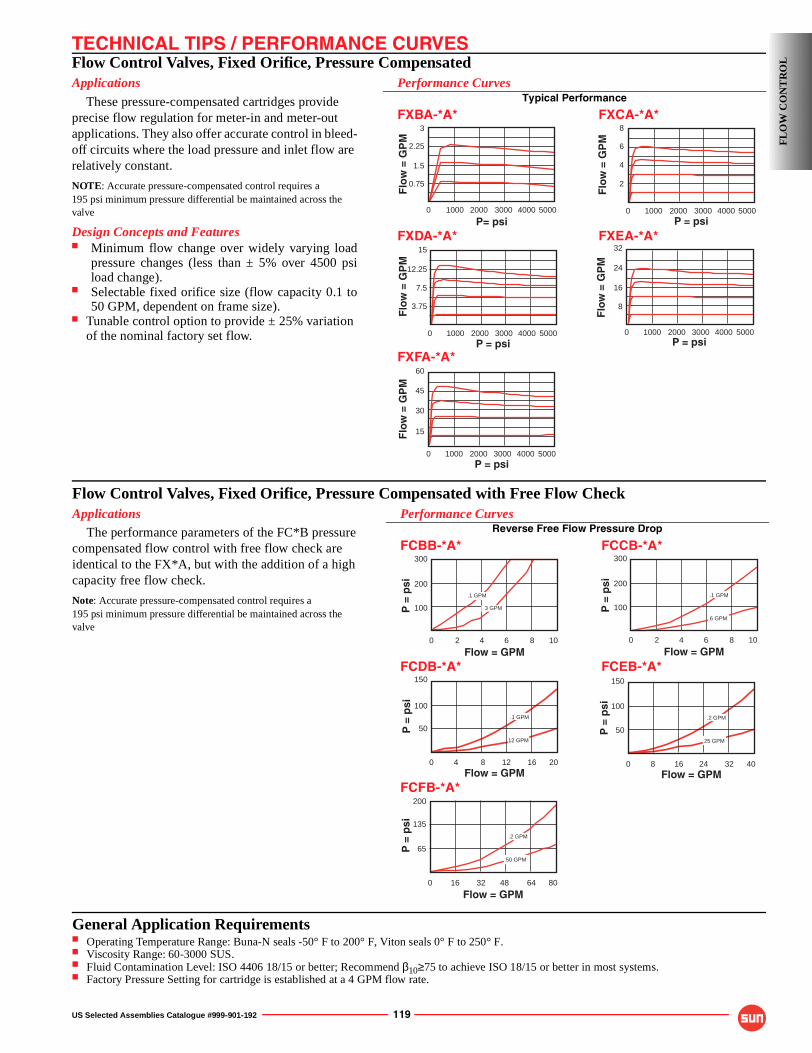
TECHNICAL TIPS / PERFORMANCE CURVES
US Selected Assemblies Catalogue #999-901-192 119
Flow Control Valves, Fixed Orifice, Pressure CompensatedApplications
These pressure-compensated cartridges provide precise flow regulation for meter-in and meter-out applications. They also offer accurate control in bleed-off circuits where the load pressure and inlet flow are relatively constant.
NOTE: Accurate pressure-compensated control requires a195 psi minimum pressure differential be maintained across the valve
Design Concepts and Features■ Minimum flow change over widely varying load
pressure changes (less than ± 5% over 4500 psiload change).
■ Selectable fixed orifice size (flow capacity 0.1 to50 GPM, dependent on frame size).
■ Tunable control option to provide ± 25% variation of the nominal factory set flow.
60
45
0 50001000 2000P = psi
Flo
w =
GP
M 30
3000 4000
15
15
12.25
7.5
0 50001000 2000P = psi
Flo
w =
GP
M
3.75
3000 4000
32
24
16
0 50001000 2000P = psi
Flo
w =
GP
M
8
3000 4000
3
2.25
0 50001000
P= psi
Flo
w =
GP
M
1.5
0.75
2000 3000 4000
8
6
4
0 50001000 2000P = psi
Flo
w =
GP
M
2
3000 4000
Performance CurvesTypical Performance
FXBA-*A* FXCA-*A*
FXDA-*A* FXEA-*A*
FXFA-*A*
FL
OW
CO
NT
RO
L
Flow Control Valves, Fixed Orifice, Pressure Compensated with Free Flow CheckApplications
The performance parameters of the FC*B pressure compensated flow control with free flow check are identical to the FX*A, but with the addition of a high capacity free flow check.
Note: Accurate pressure-compensated control requires a195 psi minimum pressure differential be maintained across the valve
Performance CurvesReverse Free Flow Pressure Drop
FCBB-*A* FCCB-*A*
FCDB-*A* FCEB-*A*
FCFB-*A*
300
200
100
0 102 4
Flow = GPM
P =
psi
6 8
.1 GPM
3 GPM
150
100
50
0 408 16Flow = GPM
P =
psi
24 32
.2 GPM
25 GPM
200
65
0 8016 32
Flow = GPM
P =
psi
48 64
135
.2 GPM
50 GPM
300
200
100
0 102 4
Flow = GPM
P =
psi
6 8
.1 GPM
6 GPM
150
100
50
0 204 8
Flow = GPM
P =
psi
12 16
.1 GPM
12 GPM
General Application Requirements■ Operating Temperature Range: Buna-N seals -50° F to 200° F, Viton seals 0° F to 250° F.■ Viscosity Range: 60-3000 SUS.■ Fluid Contamination Level: ISO 4406 18/15 or better; Recommend β10≥75 to achieve ISO 18/15 or better in most systems.■ Factory Pressure Setting for cartridge is established at a 4 GPM flow rate.
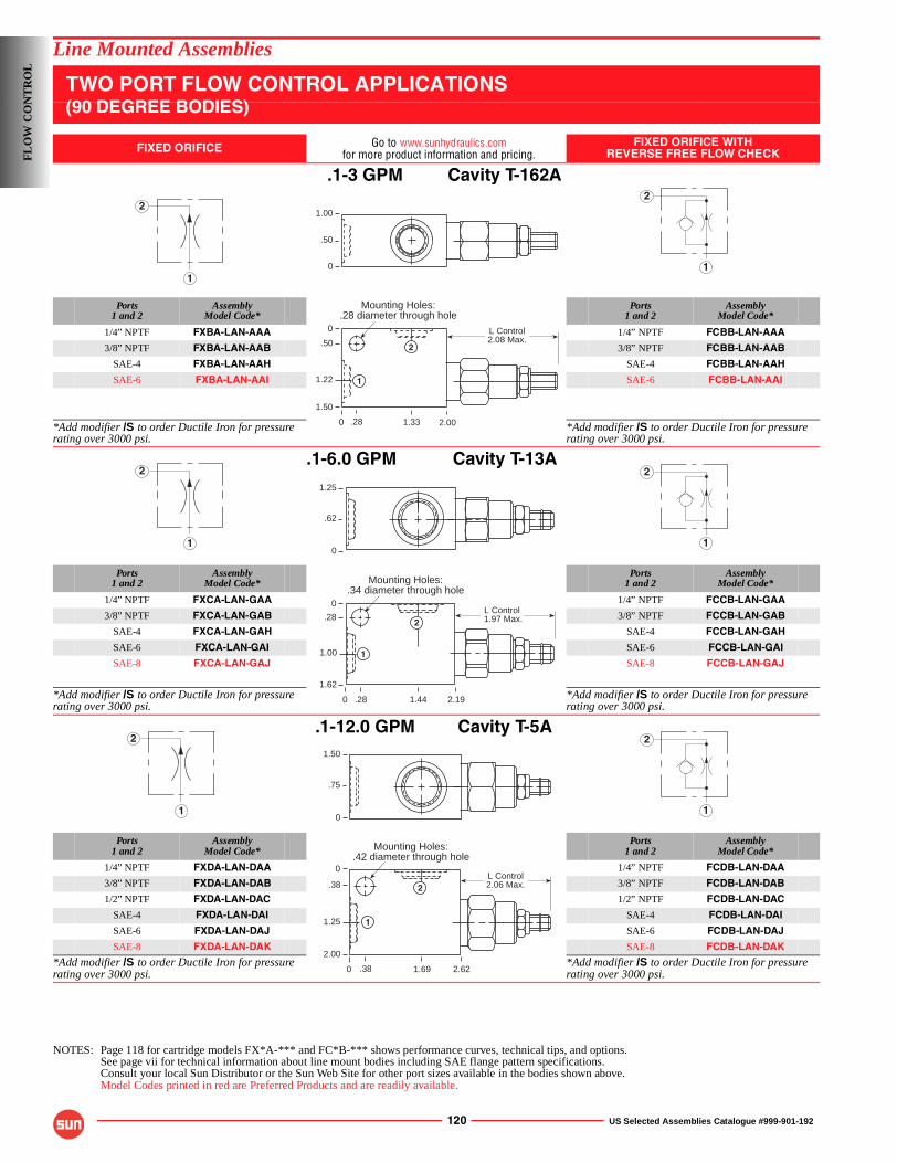
120 US Selected Assemblies Catalogue #999-901-192
Line Mounted Assemblies
TWO PORT FLOW CONTROL APPLICATIONS(90 DEGREE BODIES)
FIXED ORIFICE Go to www.sunhydraulics.comfor more product information and pricing.
FIXED ORIFICE WITHREVERSE FREE FLOW CHECK
.1-3 GPM Cavity T-162A
Ports1 and 2
AssemblyModel Code*
Ports1 and 2
AssemblyModel Code*
1/4” NPTF FXBA-LAN-AAA 1/4” NPTF FCBB-LAN-AAA
3/8” NPTF FXBA-LAN-AAB 3/8” NPTF FCBB-LAN-AAB
SAE-4 FXBA-LAN-AAH SAE-4 FCBB-LAN-AAH
SAE-6 FXBA-LAN-AAI SAE-6 FCBB-LAN-AAI
*Add modifier /S to order Ductile Iron for pressure rating over 3000 psi.
*Add modifier /S to order Ductile Iron for pressure rating over 3000 psi.
.1-6.0 GPM Cavity T-13A
Ports1 and 2
AssemblyModel Code*
Ports1 and 2
AssemblyModel Code*
1/4” NPTF FXCA-LAN-GAA 1/4” NPTF FCCB-LAN-GAA
3/8” NPTF FXCA-LAN-GAB 3/8” NPTF FCCB-LAN-GAB
SAE-4 FXCA-LAN-GAH SAE-4 FCCB-LAN-GAH
SAE-6 FXCA-LAN-GAI SAE-6 FCCB-LAN-GAI
SAE-8 FXCA-LAN-GAJ SAE-8 FCCB-LAN-GAJ
*Add modifier /S to order Ductile Iron for pressure rating over 3000 psi.
*Add modifier /S to order Ductile Iron for pressure rating over 3000 psi.
.1-12.0 GPM Cavity T-5A
Ports1 and 2
AssemblyModel Code*
Ports1 and 2
AssemblyModel Code*
1/4” NPTF FXDA-LAN-DAA 1/4” NPTF FCDB-LAN-DAA
3/8” NPTF FXDA-LAN-DAB 3/8” NPTF FCDB-LAN-DAB
1/2” NPTF FXDA-LAN-DAC 1/2” NPTF FCDB-LAN-DAC
SAE-4 FXDA-LAN-DAI SAE-4 FCDB-LAN-DAI
SAE-6 FXDA-LAN-DAJ SAE-6 FCDB-LAN-DAJ
SAE-8 FXDA-LAN-DAK SAE-8 FCDB-LAN-DAK
*Add modifier /S to order Ductile Iron for pressure rating over 3000 psi.
*Add modifier /S to order Ductile Iron for pressure rating over 3000 psi.
NOTES: Page 118 for cartridge models FX*A-*** and FC*B-*** shows performance curves, technical tips, and options.See page vii for technical information about line mount bodies including SAE flange pattern specifications.Consult your local Sun Distributor or the Sun Web Site for other port sizes available in the bodies shown above.Model Codes printed in red are Preferred Products and are readily available.
1
2
1
21.00
.50
0
Mounting Holes:.28 diameter through hole
0
0
.50
1.22
1.50
2.001.33.28
L Control2.08 Max.
1
2
1
2
1
2
Mounting Holes:.34 diameter through hole
0
0
.28
1.00
1.62
2.191.44
1.25
.62
0
.28
L Control 1.97 Max.
1
2
1
2
1
2
Mounting Holes:.42 diameter through hole
0
0
.38
1.25
2.00
2.621.69
1.50
.75
0
.38
L Control2.06 Max.
1
2
FL
OW
CO
NT
RO
L
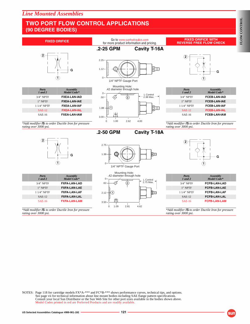
US Selected Assemblies Catalogue #999-901-192 121
Line Mounted Assemblies
TWO PORT FLOW CONTROL APPLICATIONS(90 DEGREE BODIES)
FIXED ORIFICE Go to www.sunhydraulics.comfor more product information and pricing.
FIXED ORIFICE WITHREVERSE FREE FLOW CHECK
.2-25 GPM Cavity T-16A
Ports1 and 2
AssemblyModel Code*
Ports1 and 2
AssemblyModel Code*
3/4” NPTF FXEA-LAN-IAD 3/4” NPTF FCEB-LAN-IAD
1” NPTF FXEA-LAN-IAE 1” NPTF FCEB-LAN-IAE
1 1/4” NPTF FXEA-LAN-IAF 1 1/4” NPTF FCEB-LAN-IAF
SAE-12 FXEA-LAN-IAL SAE-12 FCEB-LAN-IAL
SAE-16 FXEA-LAN-IAM SAE-16 FCEB-LAN-IAM
*Add modifier /S to order Ductile Iron for pressure rating over 3000 psi.
*Add modifier /S to order Ductile Iron for pressure rating over 3000 psi.
.2-50 GPM Cavity T-18A
Ports1 and 2
AssemblyModel Code*
Ports1 and 2
AssemblyModel Code*
3/4” NPTF FXFA-LAN-LAD 3/4” NPTF FCFB-LAN-LAD
1” NPTF FXFA-LAN-LAE 1” NPTF FCFB-LAN-LAE
1 1/4” NPTF FXFA-LAN-LAF 1 1/4” NPTF FCFB-LAN-LAF
SAE-12 FXFA-LAN-LAL SAE-12 FCFB-LAN-LAL
SAE-16 FXFA-LAN-LAM SAE-16 FCFB-LAN-LAM
*Add modifier /S to order Ductile Iron for pressure rating over 3000 psi.
*Add modifier /S to order Ductile Iron for pressure rating over 3000 psi.
NOTES: Page 118 for cartridge models FX*A-*** and FC*B-*** shows performance curves, technical tips, and options.See page vii for technical information about line mount bodies including SAE flange pattern specifications.Consult your local Sun Distributor or the Sun Web Site for other port sizes available in the bodies shown above.Model Codes printed in red are Preferred Products and are readily available.
1
2
G
1
2
G
Mounting Hole:.42 diameter through hole
0
2.25
1.12
.50
1.88
3.00
4.002.621.00
1/4” NPTF Gauge Port
0
0
L Control2.38 Max.
G
1
2
1
2
G
1
2
G
2.75
0
1.38
1/4” NPTF Gauge Port
Mounting Hole:.42 diameter through hole
3.50
.62
0
2.12
0 2.81 4.621.09
L Control2.75 Max.
1
G
2
FL
OW
CO
NT
RO
L
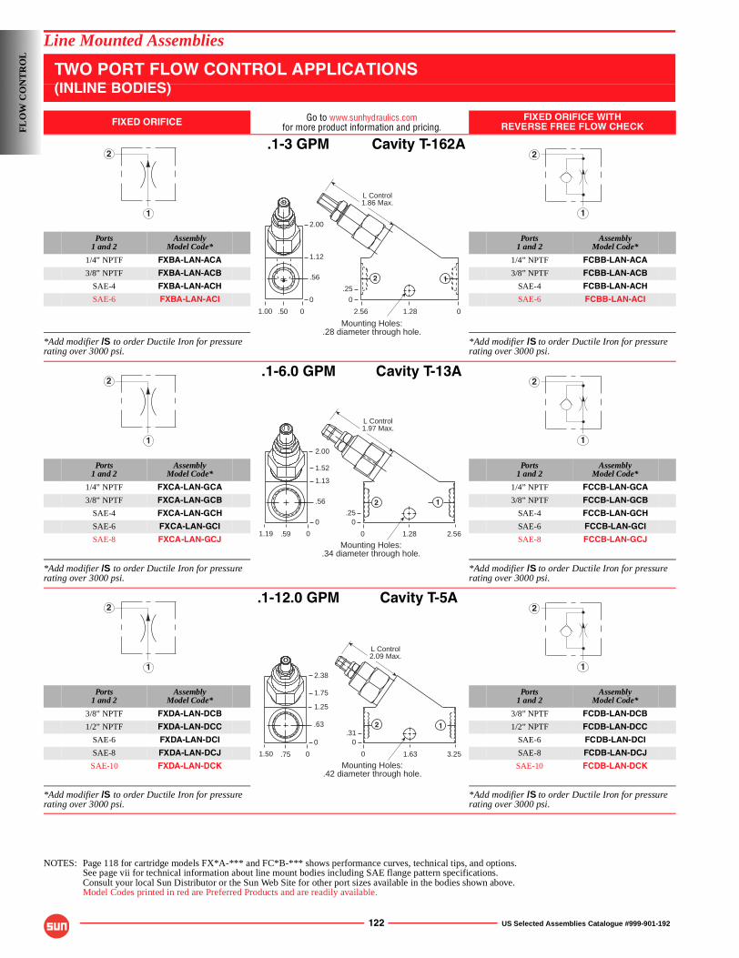
122 US Selected Assemblies Catalogue #999-901-192
Line Mounted Assemblies
TWO PORT FLOW CONTROL APPLICATIONS(INLINE BODIES)
FIXED ORIFICE Go to www.sunhydraulics.comfor more product information and pricing.
FIXED ORIFICE WITHREVERSE FREE FLOW CHECK
.1-3 GPM Cavity T-162A
Ports1 and 2
AssemblyModel Code*
Ports1 and 2
AssemblyModel Code*
1/4” NPTF FXBA-LAN-ACA 1/4” NPTF FCBB-LAN-ACA
3/8” NPTF FXBA-LAN-ACB 3/8” NPTF FCBB-LAN-ACB
SAE-4 FXBA-LAN-ACH SAE-4 FCBB-LAN-ACH
SAE-6 FXBA-LAN-ACI SAE-6 FCBB-LAN-ACI
*Add modifier /S to order Ductile Iron for pressure rating over 3000 psi.
*Add modifier /S to order Ductile Iron for pressure rating over 3000 psi.
.1-6.0 GPM Cavity T-13A
Ports1 and 2
AssemblyModel Code*
Ports1 and 2
AssemblyModel Code*
1/4” NPTF FXCA-LAN-GCA 1/4” NPTF FCCB-LAN-GCA
3/8” NPTF FXCA-LAN-GCB 3/8” NPTF FCCB-LAN-GCB
SAE-4 FXCA-LAN-GCH SAE-4 FCCB-LAN-GCH
SAE-6 FXCA-LAN-GCI SAE-6 FCCB-LAN-GCI
SAE-8 FXCA-LAN-GCJ SAE-8 FCCB-LAN-GCJ
*Add modifier /S to order Ductile Iron for pressure rating over 3000 psi.
*Add modifier /S to order Ductile Iron for pressure rating over 3000 psi.
.1-12.0 GPM Cavity T-5A
Ports1 and 2
AssemblyModel Code*
Ports1 and 2
AssemblyModel Code*
3/8” NPTF FXDA-LAN-DCB 3/8” NPTF FCDB-LAN-DCB
1/2” NPTF FXDA-LAN-DCC 1/2” NPTF FCDB-LAN-DCC
SAE-6 FXDA-LAN-DCI SAE-6 FCDB-LAN-DCI
SAE-8 FXDA-LAN-DCJ SAE-8 FCDB-LAN-DCJ
SAE-10 FXDA-LAN-DCK SAE-10 FCDB-LAN-DCK
*Add modifier /S to order Ductile Iron for pressure rating over 3000 psi.
*Add modifier /S to order Ductile Iron for pressure rating over 3000 psi.
NOTES: Page 118 for cartridge models FX*A-*** and FC*B-*** shows performance curves, technical tips, and options.See page vii for technical information about line mount bodies including SAE flange pattern specifications.Consult your local Sun Distributor or the Sun Web Site for other port sizes available in the bodies shown above.Model Codes printed in red are Preferred Products and are readily available.
1
2
1
2
Mounting Holes:.28 diameter through hole.
2.56
1.12
.56
0
01.28
.25
.501.00
2.00
0
0
L Control1.86 Max.
2 1
1
2
1
2
Mounting Holes:.34 diameter through hole.
0
1.52
1.13
.56
0
2.561.28
.25
.591.19
2.00
0
0
L Control1.97 Max.
2 1
1
2
1
2
0
1.75
1.25
.63
0
3.251.63
.31
.751.50
2.38
0
0
L Control2.09 Max.
2
Mounting Holes:.42 diameter through hole.
1
FL
OW
CO
NT
RO
L
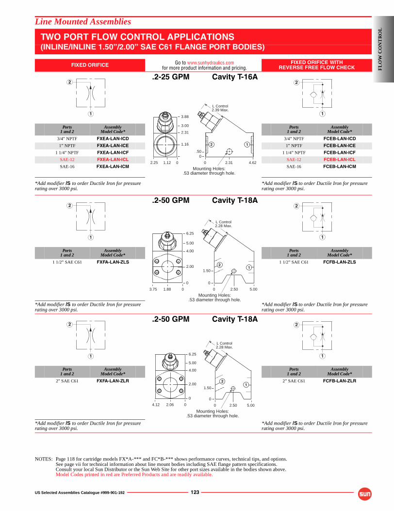
US Selected Assemblies Catalogue #999-901-192 123
Line Mounted Assemblies
TWO PORT FLOW CONTROL APPLICATIONS(INLINE/INLINE 1.50”/2.00” SAE C61 FLANGE PORT BODIES)
FIXED ORIFICE Go to www.sunhydraulics.comfor more product information and pricing.
FIXED ORIFICE WITHREVERSE FREE FLOW CHECK
.2-25 GPM Cavity T-16A
Ports1 and 2
AssemblyModel Code*
Ports1 and 2
AssemblyModel Code*
3/4” NPTF FXEA-LAN-ICD 3/4” NPTF FCEB-LAN-ICD
1” NPTF FXEA-LAN-ICE 1” NPTF FCEB-LAN-ICE
1 1/4” NPTF FXEA-LAN-ICF 1 1/4” NPTF FCEB-LAN-ICF
SAE-12 FXEA-LAN-ICL SAE-12 FCEB-LAN-ICL
SAE-16 FXEA-LAN-ICM SAE-16 FCEB-LAN-ICM
*Add modifier /S to order Ductile Iron for pressure rating over 3000 psi.
*Add modifier /S to order Ductile Iron for pressure rating over 3000 psi.
.2-50 GPM Cavity T-18A
Ports1 and 2
AssemblyModel Code*
Ports1 and 2
AssemblyModel Code*
1 1/2” SAE C61 FXFA-LAN-ZLS 1 1/2” SAE C61 FCFB-LAN-ZLS
*Add modifier /S to order Ductile Iron for pressure rating over 3000 psi.
*Add modifier /S to order Ductile Iron for pressure rating over 3000 psi.
.2-50 GPM Cavity T-18A
Ports1 and 2
AssemblyModel Code*
Ports1 and 2
AssemblyModel Code*
2” SAE C61 FXFA-LAN-ZLR 2” SAE C61 FCFB-LAN-ZLR
*Add modifier /S to order Ductile Iron for pressure rating over 3000 psi.
*Add modifier /S to order Ductile Iron for pressure rating over 3000 psi.
NOTES: Page 118 for cartridge models FX*A-*** and FC*B-*** shows performance curves, technical tips, and options.See page vii for technical information about line mount bodies including SAE flange pattern specifications.Consult your local Sun Distributor or the Sun Web Site for other port sizes available in the bodies shown above.Model Codes printed in red are Preferred Products and are readily available.
1
2
1
2
Mounting Holes:.53 diameter through hole.
0
3.00
2.31
1.16
4.622.31
.50
1.122.25
3.88
0
0
L Control2.39 Max.
2 1
1
2
1
2
Mounting Holes:.53 diameter through hole.
0
5.00
4.00
2.00
0
5.002.50
12
1.50
1.883.75
6.25
0
0
L Control2.28 Max.
1
2
1
2
Mounting Holes:.53 diameter through hole.
0
5.00
4.00
2.00
0
5.002.50
12
1.50
2.064.12
6.25
0
0
L Control2.28 Max.
FL
OW
CO
NT
RO
L
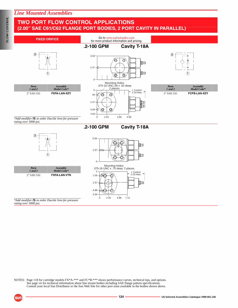
124 US Selected Assemblies Catalogue #999-901-192
Line Mounted Assemblies
TWO PORT FLOW CONTROL APPLICATIONS(2.00” SAE C61/C62 FLANGE PORT BODIES, 2 PORT CAVITY IN PARALLEL)
FIXED ORIFICE Go to www.sunhydraulics.comfor more product information and pricing.
.2-100 GPM Cavity T-18A
Ports1 and 2
AssemblyModel Code*
Ports1 and 2
AssemblyModel Code*
2” SAE C61 FXFA-LAN-XZY 2” SAE C61 FCFB-LAN-XZY
*Add modifier /S to order Ductile Iron for pressure rating over 3000 psi.
.2-100 GPM Cavity T-18A
Ports1 and 2
AssemblyModel Code*
2” SAE C62 FXFA-LAN-VTN
*Add modifier /S to order Ductile Iron for pressure rating over 3000 psi.
NOTES: Page 118 for cartridge models FX*A-*** and FC*B-*** shows performance curves, technical tips, and options.See page vii for technical information about line mount bodies including SAE flange pattern specifications.Consult your local Sun Distributor or the Sun Web Site for other port sizes available in the bodies shown above.
1
2
1
2
Mounting Holes:.375-16 UNC-2B x .62 deep.
2 places.0
2.47
.94
4.00
4.940 6.564.662.03
0
4.94
2.47
L Control 2.53 Max.
1
25.94
2.97
0
0
0
1.06
2.97
5.94
7.124.882.28
4.88
Mounting Holes:.375-16 UNC x .75 deep. 2 places.
L Control 2.25 Max.
2
1
FL
OW
CO
NT
RO
L
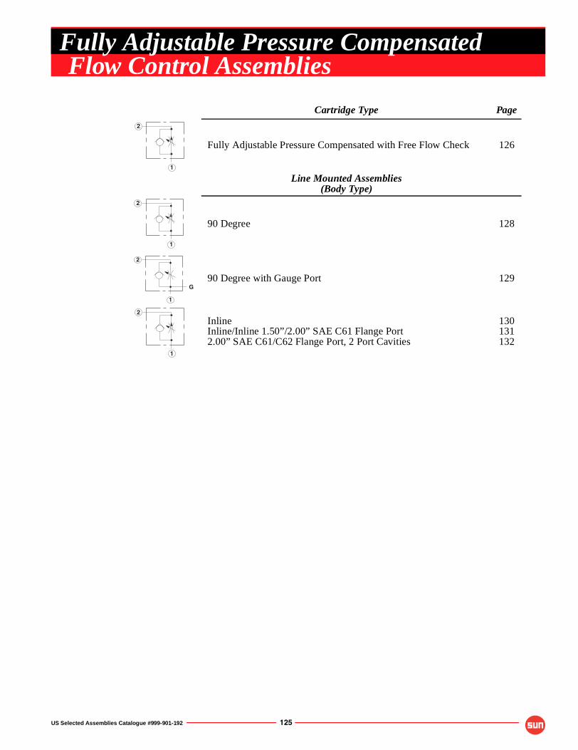
US Selected Assemblies Catalogue #999-901-192 125
Cartridge Type Page
Fully Adjustable Pressure Compensated with Free Flow Check 126
Line Mounted Assemblies(Body Type)
90 Degree 128
90 Degree with Gauge Port 129
InlineInline/Inline 1.50”/2.00” SAE C61 Flange Port2.00” SAE C61/C62 Flange Port, 2 Port Cavities
130131132
1
2
1
2
1
2
G
1
2
Fully Adjustable Pressure CompensatedFlow Control Assemblies
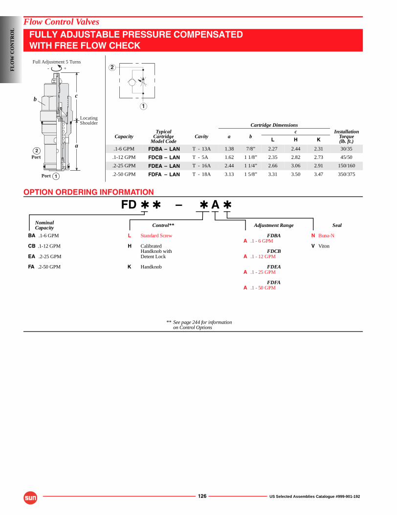
OPTION ORDERING INFORMATION
126 US Selected Assemblies Catalogue #999-901-192
Flow Control Valves
FULLY ADJUSTABLE PRESSURE COMPENSATEDWITH FREE FLOW CHECK
FD ✱ ✱ – ✱ A ✱
Nominal Control** Adjustment Range SealCapacity
BA .1-6 GPM L Standard Screw FDBA N Buna-NA .1 - 6 GPM
CB .1-12 GPM H Calibrated V VitonHandknob with FDCB
EA .2-25 GPM Detent Lock A .1 - 12 GPM
FA .2-50 GPM K Handknob FDEAA .1 - 25 GPM
FDFAA .1 - 50 GPM
** See page 244 for informationon Control Options
Cartridge Dimensions
CapacityTypical
CartridgeModel Code
Cavity a bc Installation
Torque(lb. ft.)L H K
.1-6 GPM FDBA – LAN T - 13A 1.38 7/8” 2.27 2.44 2.31 30/35
.1-12 GPM FDCB – LAN T - 5A 1.62 1 1/8” 2.35 2.82 2.73 45/50
.2-25 GPM FDEA – LAN T - 16A 2.44 1 1/4” 2.66 3.06 2.91 150/160
.2-50 GPM FDFA – LAN T - 18A 3.13 1 5/8” 3.31 3.50 3.47 350/375
- +
c
a
1
2Port
LocatingShoulder
Port
b
Full Adjustment 5 Turns
1
2FL
OW
CO
NT
RO
L
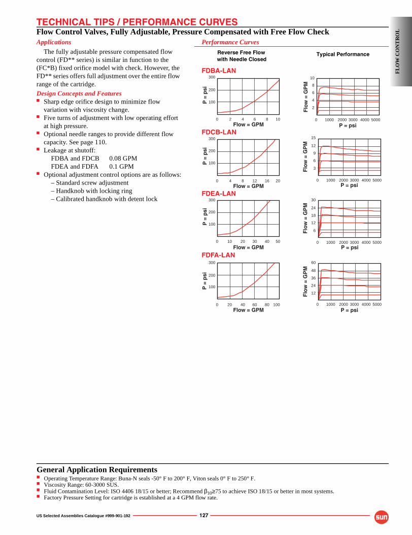
TECHNICAL TIPS / PERFORMANCE CURVES
US Selected Assemblies Catalogue #999-901-192 127
Flow Control Valves, Fully Adjustable, Pressure Compensated with Free Flow CheckApplications
The fully adjustable pressure compensated flow control (FD** series) is similar in function to the (FC*B) fixed orifice model with check. However, the FD** series offers full adjustment over the entire flow range of the cartridge.
Design Concepts and Features■ Sharp edge orifice design to minimize flow
variation with viscosity change.■ Five turns of adjustment with low operating effort
at high pressure.■ Optional needle ranges to provide different flow
capacity. See page 110.■ Leakage at shutoff:
FDBA and FDCB 0.08 GPMFDEA and FDFA 0.1 GPM
■ Optional adjustment control options are as follows:– Standard screw adjustment– Handknob with locking ring– Calibrated handknob with detent lock
Performance Curves
Reverse Free Flowwith Needle Closed
FDBA-LAN
FDCB-LAN
FDEA-LAN
FDFA-LAN
30
24
0 50004000 1000 2000 3000P = psi
Flo
w =
GP
M
18
12
6
300
200
100
0 10020 40Flow = GPM
P =
psi
60 80
60
48
0 50004000 1000 2000 3000
P = psiF
low
= G
PM
36
24
12
300
200
100
0 5010 20
Flow = GPM
P =
psi
30 40
300
200
100
0 204 8Flow = GPM
P =
psi
12 16
15
12
0 50004000 1000 2000 3000P = psi
Flo
w =
GP
M
9
6
3
300
200
100
0 102 4Flow = GPM
P =
psi
6 8
10
6
0 50004000 1000 2000 3000
P = psi
Flo
w =
GP
M
4
2
8
Typical Performance
FL
OW
CO
NT
RO
L
General Application Requirements■ Operating Temperature Range: Buna-N seals -50° F to 200° F, Viton seals 0° F to 250° F.■ Viscosity Range: 60-3000 SUS.■ Fluid Contamination Level: ISO 4406 18/15 or better; Recommend β10≥75 to achieve ISO 18/15 or better in most systems.■ Factory Pressure Setting for cartridge is established at a 4 GPM flow rate.
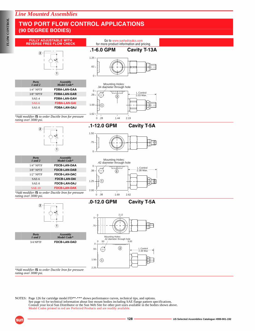
128 US Selected Assemblies Catalogue #999-901-192
Line Mounted Assemblies
TWO PORT FLOW CONTROL APPLICATIONS(90 DEGREE BODIES)
FULLY ADJUSTABLE WITHREVERSE FREE FLOW CHECK
Go to www.sunhydraulics.comfor more product information and pricing.
.1-6.0 GPM Cavity T-13A
Ports1 and 2
AssemblyModel Code*
1/4” NPTF FDBA-LAN-GAA
3/8” NPTF FDBA-LAN-GAB
SAE-4 FDBA-LAN-GAH
SAE-6 FDBA-LAN-GAI
SAE-8 FDBA-LAN-GAJ
*Add modifier /S to order Ductile Iron for pressure rating over 3000 psi.
.1-12.0 GPM Cavity T-5A
Ports1 and 2
AssemblyModel Code*
1/4” NPTF FDCB-LAN-DAA
3/8” NPTF FDCB-LAN-DAB
1/2” NPTF FDCB-LAN-DAC
SAE-6 FDCB-LAN-DAI
SAE-8 FDCB-LAN-DAJ
SAE-10 FDCB-LAN-DAK
*Add modifier /S to order Ductile Iron for pressure rating over 3000 psi.
.0-12.0 GPM Cavity T-5A
Ports1 and 2
AssemblyModel Code*
3/4 NPTF FDCB-LAN-DAD
*Add modifier /S to order Ductile Iron for pressure rating over 3000 psi.
NOTES: Page 126 for cartridge model FD**-*** shows performance curves, technical tips, and options.See page vii for technical information about line mount bodies including SAE flange pattern specifications.Consult your local Sun Distributor or the Sun Web Site for other port sizes available in the bodies shown above.Model Codes printed in red are Preferred Products and are readily available.
1
2
Mounting Holes:.34 diameter through hole
0
0
.28
1.00
1.62
2.191.44
1.25
.62
0
.28
L Control2.03 Max.
1
2
1
2
Mounting Holes:.42 diameter through hole
0
0
.38
1.25
2.00
2.621.69
1.50
.75
0
.38
L Control2.38 Max.
1
2
1
2
2
1
00 2.12
.75
0 .500
3.00
2.25
1.50
.50 L Control2.38 Max
Mounting Holes:.42 diameter through hole
FL
OW
CO
NT
RO
L
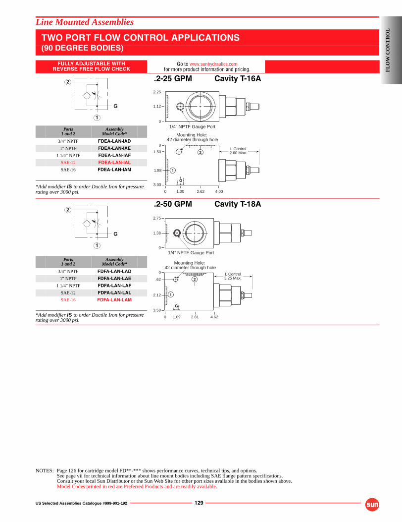
US Selected Assemblies Catalogue #999-901-192 129
Line Mounted Assemblies
TWO PORT FLOW CONTROL APPLICATIONS(90 DEGREE BODIES)
FULLY ADJUSTABLE WITHREVERSE FREE FLOW CHECK
Go to www.sunhydraulics.comfor more product information and pricing.
.2-25 GPM Cavity T-16A
Ports1 and 2
AssemblyModel Code*
3/4” NPTF FDEA-LAN-IAD
1” NPTF FDEA-LAN-IAE
1 1/4” NPTF FDEA-LAN-IAF
SAE-12 FDEA-LAN-IAL
SAE-16 FDEA-LAN-IAM
*Add modifier /S to order Ductile Iron for pressure rating over 3000 psi.
.2-50 GPM Cavity T-18A
Ports1 and 2
AssemblyModel Code*
3/4” NPTF FDFA-LAN-LAD
1” NPTF FDFA-LAN-LAE
1 1/4” NPTF FDFA-LAN-LAF
SAE-12 FDFA-LAN-LAL
SAE-16 FDFA-LAN-LAM
*Add modifier /S to order Ductile Iron for pressure rating over 3000 psi.
NOTES: Page 126 for cartridge model FD**-*** shows performance curves, technical tips, and options.See page vii for technical information about line mount bodies including SAE flange pattern specifications.Consult your local Sun Distributor or the Sun Web Site for other port sizes available in the bodies shown above.Model Codes printed in red are Preferred Products and are readily available.
1
2
G
Mounting Hole:.42 diameter through hole
0
2.25
1.12
1.50
1.88
3.00
4.002.621.00
1/4” NPTF Gauge Port
0
0
L Control2.60 Max.
G
1
2
1
2
G
2.75
0
1.38
1/4” NPTF Gauge Port
Mounting Hole:.42 diameter through hole
3.50
.62
0
2.12
0 2.81 4.621.09
L Control3.25 Max.
1
G
2
FL
OW
CO
NT
RO
L
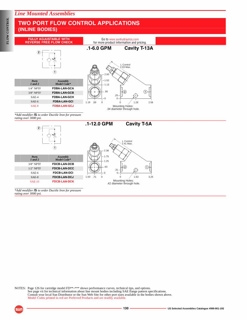
130 US Selected Assemblies Catalogue #999-901-192
Line Mounted Assemblies
TWO PORT FLOW CONTROL APPLICATIONS(INLINE BODIES)
FULLY ADJUSTABLE WITHREVERSE FREE FLOW CHECK
Go to www.sunhydraulics.comfor more product information and pricing.
.1-6.0 GPM Cavity T-13A
Ports1 and 2
AssemblyModel Code*
1/4” NPTF FDBA-LAN-GCA
3/8” NPTF FDBA-LAN-GCB
SAE-4 FDBA-LAN-GCH
SAE-6 FDBA-LAN-GCI
SAE-8 FDBA-LAN-GCJ
*Add modifier /S to order Ductile Iron for pressure rating over 3000 psi.
.1-12.0 GPM Cavity T-5A
Ports1 and 2
AssemblyModel Code*
3/8” NPTF FDCB-LAN-DCB
1/2” NPTF FDCB-LAN-DCC
SAE-6 FDCB-LAN-DCI
SAE-8 FDCB-LAN-DCJ
SAE-10 FDCB-LAN-DCK
*Add modifier /S to order Ductile Iron for pressure rating over 3000 psi.
NOTES: Page 126 for cartridge model FD**-*** shows performance curves, technical tips, and options.See page vii for technical information about line mount bodies including SAE flange pattern specifications.Consult your local Sun Distributor or the Sun Web Site for other port sizes available in the bodies shown above.Model Codes printed in red are Preferred Products and are readily available.
1
2
Mounting Holes:.34 diameter through hole.
0
1.52
1.13
.56
0
2.561.28
.25
.591.19
2.00
0
0
L Control2.03 Max.
2 1
1
2
0
1.75
1.25
.63
0
3.251.63
.31
.751.50
2.38
0
0
L Control2.41 Max.
2
Mounting Holes:.42 diameter through hole.
1
FL
OW
CO
NT
RO
L
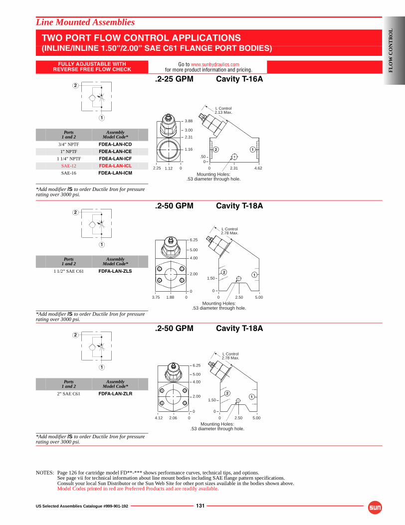
US Selected Assemblies Catalogue #999-901-192 131
Line Mounted Assemblies
TWO PORT FLOW CONTROL APPLICATIONS(INLINE/INLINE 1.50”/2.00” SAE C61 FLANGE PORT BODIES)
FULLY ADJUSTABLE WITHREVERSE FREE FLOW CHECK
Go to www.sunhydraulics.comfor more product information and pricing.
.2-25 GPM Cavity T-16A
Ports1 and 2
AssemblyModel Code*
3/4” NPTF FDEA-LAN-ICD
1” NPTF FDEA-LAN-ICE
1 1/4” NPTF FDEA-LAN-ICF
SAE-12 FDEA-LAN-ICL
SAE-16 FDEA-LAN-ICM
*Add modifier /S to order Ductile Iron for pressure rating over 3000 psi.
.2-50 GPM Cavity T-18A
Ports1 and 2
AssemblyModel Code*
1 1/2” SAE C61 FDFA-LAN-ZLS
*Add modifier /S to order Ductile Iron for pressure rating over 3000 psi.
.2-50 GPM Cavity T-18A
Ports1 and 2
AssemblyModel Code*
2” SAE C61 FDFA-LAN-ZLR
*Add modifier /S to order Ductile Iron for pressure rating over 3000 psi.
NOTES: Page 126 for cartridge model FD**-*** shows performance curves, technical tips, and options.See page vii for technical information about line mount bodies including SAE flange pattern specifications.Consult your local Sun Distributor or the Sun Web Site for other port sizes available in the bodies shown above.Model Codes printed in red are Preferred Products and are readily available.
1
2
Mounting Holes:.53 diameter through hole.
0
3.00
2.31
1.16
4.622.31
.50
1.122.25
3.88
0
0
L Control2.13 Max.
2 1
1
2
Mounting Holes:.53 diameter through hole.
0
5.00
4.00
2.00
0
5.002.50
12
1.50
1.883.75
6.25
0
0
L Control2.78 Max.
1
2
Mounting Holes:.53 diameter through hole.
0
5.00
4.00
2.00
0
5.002.50
12
1.50
2.064.12
6.25
0
0
L Control2.78 Max.
FL
OW
CO
NT
RO
L
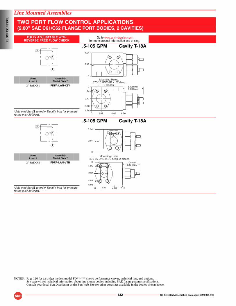
132 US Selected Assemblies Catalogue #999-901-192
Line Mounted Assemblies
TWO PORT FLOW CONTROL APPLICATIONS(2.00” SAE C61/C62 FLANGE PORT BODIES, 2 CAVITIES)
FULLY ADJUSTABLE WITHREVERSE FREE FLOW CHECK
Go to www.sunhydraulics.comfor more product information and pricing.
.5-105 GPM Cavity T-18A
Ports1 and 2
AssemblyModel Code*
2” SAE C61 FDFA-LAN-XZY
*Add modifier /S to order Ductile Iron for pressure rating over 3000 psi.
.5-105 GPM Cavity T-18A
Ports1 and 2
AssemblyModel Code*
2” SAE C62 FDFA-LAN-VTN
*Add modifier /S to order Ductile Iron for pressure rating over 3000 psi.
NOTES: Page 126 for cartridge models model FD**-*** shows performance curves, technical tips, and options.See page vii for technical information about line mount bodies including SAE flange pattern specifications.Consult your local Sun Distributor or the Sun Web Site for other port sizes available in the bodies shown above.
1
2
Mounting Holes:.375-16 UNC-2B x .62 deep.
2 places.0
2.47
.94
4.00
4.940 6.564.662.03
0
4.94
2.47
L Control 3.03 Max.
1
25.94
2.97
0
0
0
1.06
2.97
5.94
7.124.882.28
4.88
Mounting Holes:.375-16 UNC x .75 deep. 2 places.
L Control 3.23 Max.
2
1
FL
OW
CO
NT
RO
L
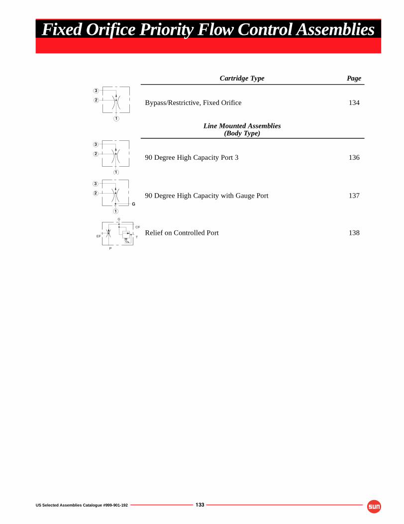
US Selected Assemblies Catalogue #999-901-192 133
Cartridge Type Page
Bypass/Restrictive, Fixed Orifice 134
Line Mounted Assemblies(Body Type)
90 Degree High Capacity Port 3 136
90 Degree High Capacity with Gauge Port 137
Relief on Controlled Port 138
1
2
3
1
2
3
G
1
2
3
EF
G
CF
P
T
Fixed Orifice Priority Flow Control Assemblies
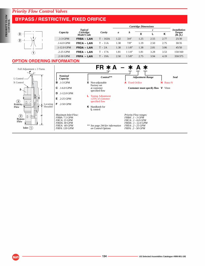
OPTION ORDERING INFORMATION
134 US Selected Assemblies Catalogue #999-901-192
Priority Flow Control Valves
BYPASS / RESTRICTIVE, FIXED ORIFICE
FR ✱ A – ✱ A ✱
Nominal Control** Adjustment Range SealCapacity
B .1-3 GPM X Non-adjustable A Fixed Orifice N Buna-NFactory set
C .1-6.0 GPM at customer Customer must specify flow V Vitonspecified flow
D .1-12.0 GPML Tuning Adjustment
E .2-25 GPM ±25% of customerspecified flow
F .2-50 GPMK Handknob for
L control
Maximum Inlet Flow: Priority Flow ranges:FRBA: 7.5 GPM FRBA: .1 - 3 GPMFRCA: 15 GPM FRCA: .1 - 6.0 GPMFRDA: 30 GPM FRDA: .1 - 12.0 GPMFREA: 60 GPM ** See page 244 for information FREA: .2 - 25 GPMFRFA: 120 GPM on Control Options FRFA: .2 - 50 GPM
Cartridge Dimensions
CapacityTypical
CartridgeModel Code
Cavity a bc Installation
Torque(lb. ft.)X L K
.1-3 GPM FRBA – LAN T - 163A 1.22 3/4” 1.25 2.55 2.77 25/30
.1-6.0 GPM FRCA – LAN T - 11A 1.38 7/8” 1.19 2.50 2.75 30/35
.1-12.0 GPM FRDA – LAN T - 2A 1.38 1 1/8” 1.38 2.81 3.06 45/50
.2-25 GPM FREA – LAN T - 17A 1.81 1 1/4” 1.81 3.28 3.53 150/160
.2-50 GPM FRFA – LAN T - 19A 2.50 1 5/8” 2.75 3.94 4.19 350/3751
2
3
-+
Full Adjustment ± 3 Turns
b c
a
1
2
3
L Control
X Control
Inlet
PriorityFlow
BypassFlow
LocatingShoulder
PR
IOR
ITY
FL
OW
C
ON
TR
OL
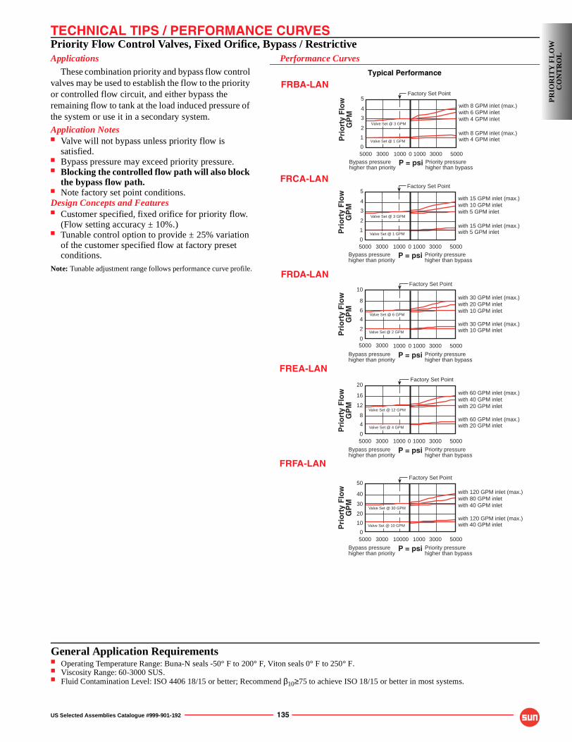
TECHNICAL TIPS / PERFORMANCE CURVES
US Selected Assemblies Catalogue #999-901-192 135
Priority Flow Control Valves, Fixed Orifice, Bypass / RestrictiveApplications
These combination priority and bypass flow control valves may be used to establish the flow to the priority or controlled flow circuit, and either bypass the remaining flow to tank at the load induced pressure of the system or use it in a secondary system.
Application Notes■ Valve will not bypass unless priority flow is
satisfied.■ Bypass pressure may exceed priority pressure.■ Blocking the controlled flow path will also block
the bypass flow path.■ Note factory set point conditions.Design Concepts and Features■ Customer specified, fixed orifice for priority flow.
(Flow setting accuracy ± 10%.)■ Tunable control option to provide ± 25% variation
of the customer specified flow at factory preset conditions.
Note: Tunable adjustment range follows performance curve profile.
Performance Curves
Typical Performance
Factory Set Point10
8
6
5000 500030003000 1000 0
2
P = psi
Pri
ort
y F
low
GP
M 1000
4
0
with 30 GPM inlet (max.)with 20 GPM inletwith 10 GPM inlet
with 30 GPM inlet (max.)with 10 GPM inlet
Bypass pressurehigher than priority
Priority pressurehigher than bypass
Valve Set @ 6 GPM
Valve Set @ 2 GPM
5
4
3
5000 500030003000 1000 0
1
P = psi
Pri
ort
y F
low
GP
M
1000
2
0
Factory Set Point
with 15 GPM inlet (max.)with 10 GPM inletwith 5 GPM inlet
with 15 GPM inlet (max.)with 5 GPM inlet
Bypass pressurehigher than priority
Priority pressurehigher than bypass
Valve Set @ 3 GPM
Valve Set @ 1 GPM
50
40
30
5000 500030003000 1000 0
10
P = psi
Pri
ort
y F
low
GP
M
1000
20
0
with 120 GPM inlet (max.)with 80 GPM inletwith 40 GPM inlet
with 120 GPM inlet (max.)with 40 GPM inlet
Bypass pressurehigher than priority
Priority pressurehigher than bypass
Valve Set @ 30 GPM
Valve Set @ 10 GPM
Factory Set Point
20
16
12
5000 500030003000 1000 0
4
P = psi
Pri
ort
y F
low
GP
M
1000
8
0
with 60 GPM inlet (max.)with 40 GPM inletwith 20 GPM inlet
with 60 GPM inlet (max.)with 20 GPM inlet
Bypass pressurehigher than priority
Priority pressurehigher than bypass
Valve Set @ 12 GPM
Valve Set @ 4 GPM
Factory Set Point
5
4
3
5000 500030003000 1000 0
1
P = psi
Pri
ort
y F
low
GP
M
1000
2
0
Factory Set Point
with 8 GPM inlet (max.)with 6 GPM inletwith 4 GPM inlet
with 8 GPM inlet (max.)with 4 GPM inlet
Bypass pressurehigher than priority
Priority pressurehigher than bypass
Valve Set @ 3 GPM
Valve Set @ 1 GPM
FREA-LAN
FRBA-LAN
FRFA-LAN
FRCA-LAN
FRDA-LAN
PR
IOR
ITY
FL
OW
C
ON
TR
OL
General Application Requirements■ Operating Temperature Range: Buna-N seals -50° F to 200° F, Viton seals 0° F to 250° F.■ Viscosity Range: 60-3000 SUS.■ Fluid Contamination Level: ISO 4406 18/15 or better; Recommend β10≥75 to achieve ISO 18/15 or better in most systems.
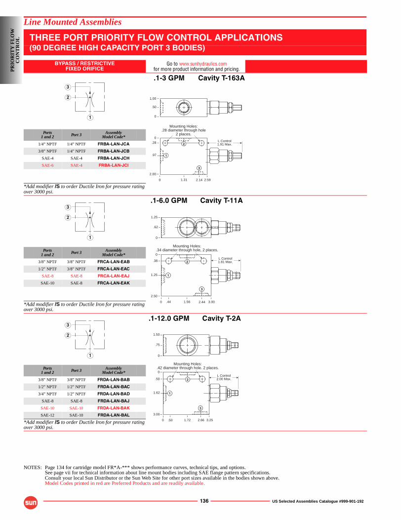
136 US Selected Assemblies Catalogue #999-901-192
Line Mounted Assemblies
THREE PORT PRIORITY FLOW CONTROL APPLICATIONS(90 DEGREE HIGH CAPACITY PORT 3 BODIES)
BYPASS / RESTRICTIVEFIXED ORIFICE
Go to www.sunhydraulics.comfor more product information and pricing.
.1-3 GPM Cavity T-163A
Ports1 and 2 Port 3 Assembly
Model Code*
1/4” NPTF 1/4” NPTF FRBA-LAN-JCA
3/8” NPTF 1/4” NPTF FRBA-LAN-JCB
SAE-4 SAE-4 FRBA-LAN-JCH
SAE-6 SAE-4 FRBA-LAN-JCI
*Add modifier /S to order Ductile Iron for pressure rating over 3000 psi.
.1-6.0 GPM Cavity T-11A
Ports1 and 2 Port 3 Assembly
Model Code*
3/8” NPTF 3/8” NPTF FRCA-LAN-EAB
1/2” NPTF 3/8” NPTF FRCA-LAN-EAC
SAE-8 SAE-8 FRCA-LAN-EAJ
SAE-10 SAE-8 FRCA-LAN-EAK
*Add modifier /S to order Ductile Iron for pressure rating over 3000 psi.
.1-12.0 GPM Cavity T-2A
Ports1 and 2 Port 3 Assembly
Model Code*
3/8” NPTF 3/8” NPTF FRDA-LAN-BAB
1/2” NPTF 1/2” NPTF FRDA-LAN-BAC
3/4” NPTF 1/2” NPTF FRDA-LAN-BAD
SAE-8 SAE-8 FRDA-LAN-BAJ
SAE-10 SAE-10 FRDA-LAN-BAK
SAE-12 SAE-10 FRDA-LAN-BAL
*Add modifier /S to order Ductile Iron for pressure rating over 3000 psi.
NOTES: Page 134 for cartridge model FR*A-*** shows performance curves, technical tips, and options.See page vii for technical information about line mount bodies including SAE flange pattern specifications.Consult your local Sun Distributor or the Sun Web Site for other port sizes available in the bodies shown above.Model Codes printed in red are Preferred Products and are readily available.
1
2
3
L Control1.91 Max.
Mounting Holes:.28 diameter through hole
2 places.
0
0.28
.97
2.00
2.592.141.31
1.00
.50
0
1
2
3
1
2
3
L Control1.81 Max.
Mounting Holes:.34 diameter through hole, 2 places.
0
0
.38
1.25
2.50
3.002.441.56
1.25
.62
0
.44
1
2
3
1
2
3
L Control2.00 Max.
1.50
.75
0
0
0
.50
1.62
3.00
3.252.661.72
Mounting Holes:.42 diameter through hole. 2 places.
.50
1
2
3
PR
IOR
ITY
FL
OW
C
ON
TR
OL
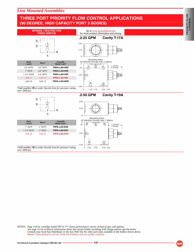
US Selected Assemblies Catalogue #999-901-192 137
Line Mounted Assemblies
THREE PORT PRIORITY FLOW CONTROL APPLICATIONS(90 DEGREE, HIGH CAPACITY PORT 3 BODIES)
BYPASS / RESTRICTIVEFIXED ORIFICE
Go to www.sunhydraulics.comfor more product information and pricing.
.2-25 GPM Cavity T-17A
Ports1 and 2 Port 3 Assembly
Model Code*
3/4” NPTF 3/4” NPTF FREA-LAN-HED
1” NPTF 3/4” NPTF FREA-LAN-HEE
1 1/4” NPTF 3/4” NPTF FREA-LAN-HEF
SAE-12 SAE-12 FREA-LAN-HEL
SAE-16 SAE-12 FREA-LAN-HEM
*Add modifier /S to order Ductile Iron for pressure rating over 3000 psi.
.2-50 GPM Cavity T-19A
Ports1 and 2 Port 3 Assembly
Model Code*
1” NPTF 1” NPTF FRFA-LAN-KEE
1 1/4” NPTF 1” NPTF FRFA-LAN-KEF
SAE-20 SAE-16 FRFA-LAN-KEN
*Add modifier /S to order Ductile Iron for pressure rating over 3000 psi.
NOTES: Page 134 for cartridge model FR*A-*** shows performance curves, technical tips, and options.See page vii for technical information about line mount bodies including SAE flange pattern specifications.Consult your local Sun Distributor or the Sun Web Site for other port sizes available in the bodies shown above.Model Codes printed in red are Preferred Products and are readily available.
G
1
2
3
L Control2.16 Max.
Mounting Holes:.42 diameter through hole, 2 places.
0
0
.75
2.00
4.00
4.253.442.12
2.25
1.12
0
1.19
G
1
2
3
G
1
2
3
0
0.50
2.50
5.00
5.254.312.50
L Control2.56 Max.
Mounting Holes:.42 diameter through hole, 2 places.
3.00
1.50
0
1.06
G
1
2
3
PR
IOR
ITY
FL
OW
C
ON
TR
OL
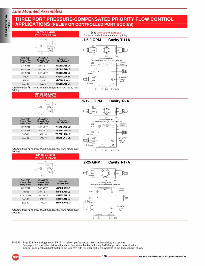
138 US Selected Assemblies Catalogue #999-901-192
Line Mounted Assemblies
THREE PORT PRESSURE-COMPENSATED PRIORITY FLOW CONTROL APPLICATIONS (RELIEF ON CONTROLLED PORT BODIES)
UP TO 6.5 GPMPRIORITY FLOW
Go to www.sunhydraulics.comfor more product information and pricing.
.1-6.0 GPM Cavity T-11A
Ports (EF)Excess Flow& (P) Pump
Ports (CF)Control Flow& (T) Tank
AssemblyModel Code*
1/4” NPTF 1/4” NPTF YRDR-LAN-LA
3/8” NPTF 3/8” NPTF YRDR-LAN-LB
1/2” NPTF 3/8” NPTF YRDR-LAN-LC
SAE-6 SAE-6 YRDR-LAN-LI
SAE-8 SAE-8 YRDR-LAN-LJ
SAE-10 SAE-8 YRDR-LAN-LK
*Add modifier /S to order Ductile Iron for pressure rating over 3000 psi.
UP TO 12.5 GPMPRIORITY FLOW
.1-12.0 GPM Cavity T-2A
Ports (EF)Excess Flow& (P) Pump
Ports (CF)Control Flow& (T) Tank
AssemblyModel Code*
1/2” NPTF 1/2” NPTF YREM-LAN-LC
3/4” NPTF 1/2” NPTF YREM-LAN-LD
SAE-10 SAE-10 YREM-LAN-LK
SAE-12 SAE-10 YREM-LAN-LL
*Add modifier /S to order Ductile Iron for pressure rating over 3000 psi.
UP TO 25 GPMPRIORITY FLOW
.2-25 GPM Cavity T-17A
Ports (EF)Excess Flow& (P) Pump
Ports (CF)Control Flow& (T) Tank
AssemblyModel Code*
3/4” NPTF 3/4” NPTF YRFF-LAN-LD
1” NPTF 3/4” NPTF YRFF-LAN-LE
1 1/4” NPTF 3/4” NPTF YRFF-LAN-LF
SAE-12 SAE-12 YRFF-LAN-LL
SAE-16 SAE-12 YRFF-LAN-LM
*Add modifier /S to order Ductile Iron for pressure rating over 3000 psi.
NOTES: Page 134 for cartridge model FR*A-*** shows performance curves, technical tips, and options.See page vii for technical information about line mount bodies including SAE flange pattern specifications.Consult your local Sun Distributor or the Sun Web Site for other port sizes available in the bodies shown above.
EF
G
CF
P
T
0
1.50
1.69 3.62
L Control1.69 Max.
0
3.623.25
0
3.252.661.69.97
Mounting Holes:.34 diameter through hole. 2 places.
1.94 Max.
L Control
2.12
1/4” NPTFGauge
PortG
T CF
EF
P
EF
G
CF
P
T
0
1.50
1.69 3.62
L Control1.69 Max.
0
3.623.25
0
3.252.661.69.97
Mounting Holes:.34 diameter through hole. 2 places.
1.94 Max.
1/4” NPTFGauge
PortL Control
2.12
G
T CF
EF
P
EF
G
CF
P
T
5.25
2.25
0
0 2.09
0
0
4.003.19
L Control2.38 Max.
Mounting Holes:.41 diameter through hole. 2 places.
.88
5.25
4.50
L Control1.94 Max.
1/4” NPTFGauge
Port
3.25
G
T CF
EF
P
PR
IOR
ITY
FL
OW
C
ON
TR
OL
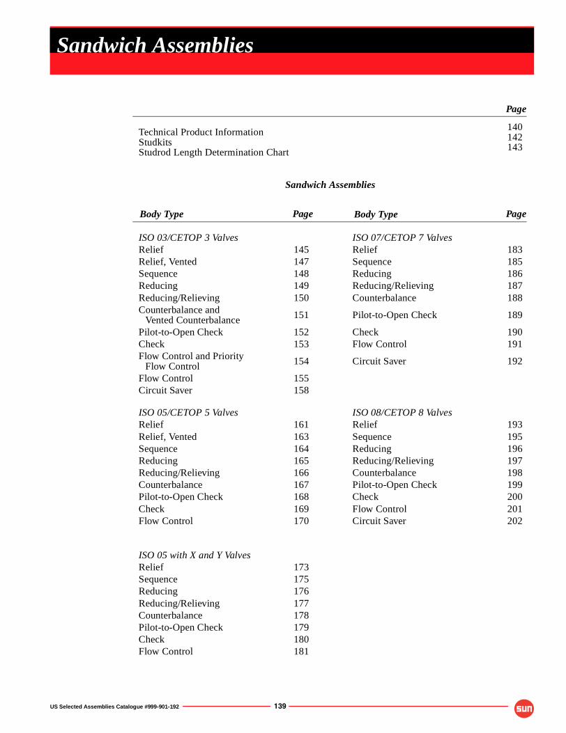
US Selected Assemblies Catalogue #999-901-192 139
Technical Product InformationStudkitsStudrod Length Determination Chart
140142143
Sandwich Assemblies
ISO 03/CETOP 3 Valves ISO 07/CETOP 7 ValvesRelief 145 Relief 183Relief, Vented 147 Sequence 185Sequence 148 Reducing 186Reducing 149 Reducing/Relieving 187Reducing/Relieving 150 Counterbalance 188Counterbalance and
Vented Counterbalance 151 Pilot-to-Open Check 189
Pilot-to-Open Check 152 Check 190Check 153 Flow Control 191Flow Control and Priority
Flow Control 154 Circuit Saver 192
Flow Control 155Circuit Saver 158
ISO 05/CETOP 5 Valves ISO 08/CETOP 8 ValvesRelief 161 Relief 193Relief, Vented 163 Sequence 195Sequence 164 Reducing 196Reducing 165 Reducing/Relieving 197Reducing/Relieving 166 Counterbalance 198Counterbalance 167 Pilot-to-Open Check 199Pilot-to-Open Check 168 Check 200Check 169 Flow Control 201Flow Control 170 Circuit Saver 202
ISO 05 with X and Y ValvesRelief 173Sequence 175Reducing 176Reducing/Relieving 177Counterbalance 178Pilot-to-Open Check 179Check 180Flow Control 181
Sandwich Assemblies
Page
Page
PageBody TypeBody Type

140 US Selected Assemblies Catalogue #999-901-192
Sandwich Bodies
TECHNICAL PRODUCT INFORMATION
Click Here forMOUNTING and ASSEMBLY of SANDWICH BODIES
Technical Tips
See Product > Technical Information > Technical Tips for Sun Products
US Selected Assemblies Catalogue #999-901-192 141
Sandwich Bodies
TECHNICAL PRODUCT INFORMATION
Click Here forMOUNTING and ASSEMBLY of SANDWICH BODIES
Technical Tips
See Product > Technical Information > Technical Tips for Sun Products
142 US Selected Assemblies Catalogue #999-901-192
Sandwich Bodies
TECHNICAL PRODUCT INFORMATION
Click Here forMOUNTING and ASSEMBLY of SANDWICH BODIES
Technical Tips
See Product > Technical Information > Technical Tips for Sun Products

US Selected Assemblies Catalogue #999-901-192 143
Sandwich Bodies
TECHNICAL PRODUCT INFORMATION
Click Here forMOUNTING and ASSEMBLY of SANDWICH BODIES
Technical Tips
See Product > Technical Information > Technical Tips for Sun Products
144 US Selected Assemblies Catalogue #999-901-192
Sandwich Bodies
NOTES
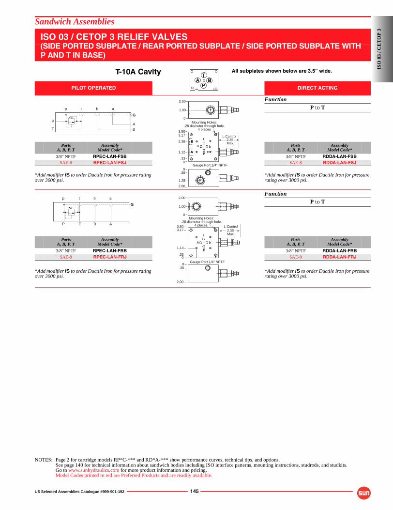
US Selected Assemblies Catalogue #999-901-192 145
Sandwich Assemblies
ISO 03 / CETOP 3 RELIEF VALVES(SIDE PORTED SUBPLATE / REAR PORTED SUBPLATE / SIDE PORTED SUBPLATE WITH P AND T IN BASE)
T-10A Cavity All subplates shown below are 3.5” wide.
PILOT OPERATED DIRECT ACTING
FunctionP to T
PortsA, B, P, T
AssemblyModel Code*
PortsA, B, P, T
AssemblyModel Code*
3/8” NPTF RPEC-LAN-FSB 3/8” NPTF RDDA-LAN-FSBSAE-8 RPEC-LAN-FSJ SAE-8 RDDA-LAN-FSJ
*Add modifier /S to order Ductile Iron for pressure rating over 3000 psi.
*Add modifier /S to order Ductile Iron for pressure rating over 3000 psi.
FunctionP to T
PortsA, B, P, T
AssemblyModel Code*
PortsA, B, P, T
AssemblyModel Code*
3/8” NPTF RPEC-LAN-FRB 3/8” NPTF RDDA-LAN-FRBSAE-8 RPEC-LAN-FRJ SAE-8 RDDA-LAN-FRJ
*Add modifier /S to order Ductile Iron for pressure rating over 3000 psi.
*Add modifier /S to order Ductile Iron for pressure rating over 3000 psi.
NOTES: Page 2 for cartridge models RP*C-*** and RD*A-*** show performance curves, technical tips, and options.See page 140 for technical information about sandwich bodies including ISO interface patterns, mounting instructions, studrods, and studkits.Go to www.sunhydraulics.com for more product information and pricing.Model Codes printed in red are Preferred Products and are readily available.
P
T BA
p t b a
GT1.00
2.00
Gauge Port 1/4” NPTF
2.00
1.25
.380
P
Mounting Holes:.28 diameter through hole.
4 places
.33
1.12
2.38
3.173.50
2.35 Max.
L Control
p
B
A
b
t
a
0
0
p t b a
G
P T B A
0.33
1.14
3.173.50
2.35 Max.
L Control
Mounting Holes:.28 diameter through hole.
4 places.
p
b
t
a
1.00
2.00
0
2.00
Gauge Port 1/4” NPTF0
.38
ISO
03
/ CE
TO
P 3
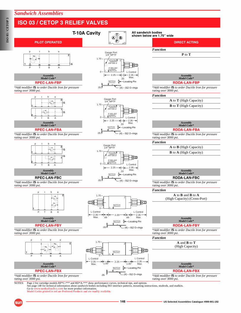
146 US Selected Assemblies Catalogue #999-901-192
Sandwich Assemblies
ISO 03 / CETOP 3 RELIEF VALVES
T-10A Cavity All sandwich bodiesshown below are 1.75” wide
PILOT OPERATED DIRECT ACTING
FunctionP to T
AssemblyModel Code*
AssemblyModel Code*
RPEC-LAN-FBP RDDA-LAN-FBP*Add modifier /S to order Ductile Iron for pressure rating over 3000 psi.
*Add modifier /S to order Ductile Iron for pressure rating over 3000 psi.
FunctionA to T (High Capacity)
B to T (High Capacity)
AssemblyModel Code*
AssemblyModel Code*
RPEC-LAN-FBA RDDA-LAN-FBA*Add modifier /S to order Ductile Iron for pressure rating over 3000 psi.
*Add modifier /S to order Ductile Iron for pressure rating over 3000 psi.
FunctionA to B (High Capacity)
B to A (High Capacity)
AssemblyModel Code*
AssemblyModel Code*
RPEC-LAN-FBC RDDA-LAN-FBC*Add modifier /S to order Ductile Iron for pressure rating over 3000 psi.
*Add modifier /S to order Ductile Iron for pressure rating over 3000 psi.
Function
A to B and B to A(High Capacity) (Cross-Port)
AssemblyModel Code*
AssemblyModel Code*
RPEC-LAN-FBY RDDA-LAN-FBY*Add modifier /S to order Ductile Iron for pressure rating over 3000 psi.
*Add modifier /S to order Ductile Iron for pressure rating over 3000 psi.
FunctionA and B to T
(High Capacity)
AssemblyModel Code*
AssemblyModel Code*
RPEC-LAN-FBX RDDA-LAN-FBX*Add modifier /S to order Ductile Iron for pressure rating over 3000 psi.
*Add modifier /S to order Ductile Iron for pressure rating over 3000 psi.
NOTES: Page 2 for cartridge models RP*C-*** and RD*A-*** show performance curves, technical tips, and options.See page 140 for technical information about sandwich bodies including ISO interface patterns, mounting instructions, studrods, and studkits.Go to www.sunhydraulics.com for more product information.Model Codes printed in red are Preferred Products and are readily available.
GP T B A
p t b a
1
2
.33
P RELIEFNOTCH1
2
2.25
Gauge Port1/4” NPTF
(4) – 012 O–rings.05
2.35 Max.
L Control
P RELIEFNOTCH1.70
Locating PinNOTCH
0
G
P T B A2
1
G
p t b a
1
2
2.25
.33
P RELIEFNOTCH1
2
Gauge Port1/4” NPTF
NOTCH
(4) – 012 O–rings
Locating Pin
.05
2.35 Max.
L Control
P RELIEFNOTCH1.70
0
G
p t b a
1
2
G
P T B A2
1
P RELIEFNOTCH1
2
.33
2.25
Gauge Port1/4” NPTF
(4) – 012 O–rings.05
2.35 Max.
L Control
1.70
P RELIEFNOTCH
Locating PinNOTCH
0
P T B A
p t b a
1
2
.69.69
1
2
2.25 2.35 Max.
L Control2.35 Max.
L Control
(4) – 012 O–rings.05
1.70
Locating PinNOTCH
NOTCH
0
P T B A
p t b a
1
2
2.251.001.00
2.35 Max.
L Control
1
2
L Control2.35 Max.
.05 (4) – 012 O–rings
1.70
NOTCH Locating Pin
NOTCH
0
ISO
03
/ CE
TO
P 3
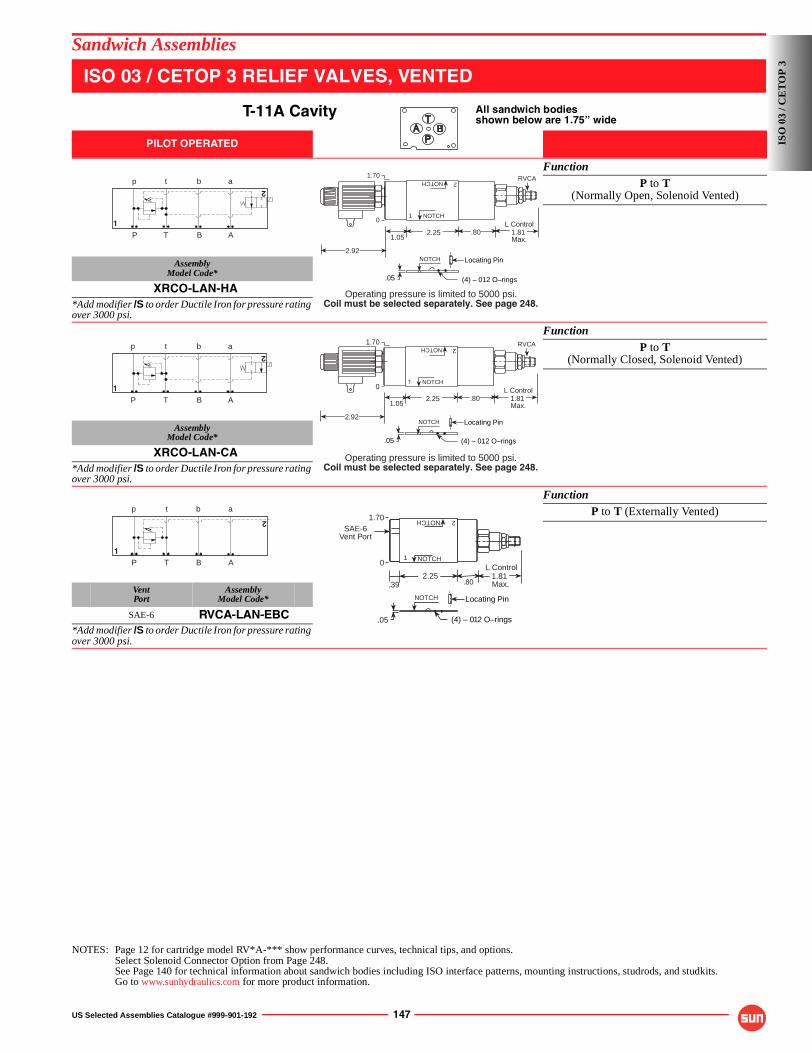
US Selected Assemblies Catalogue #999-901-192 147
Sandwich Assemblies
ISO 03 / CETOP 3 RELIEF VALVES, VENTED
T-11A Cavity All sandwich bodiesshown below are 1.75” wide
PILOT OPERATED
FunctionP to T
(Normally Open, Solenoid Vented)
AssemblyModel Code*
XRCO-LAN-HA*Add modifier /S to order Ductile Iron for pressure rating over 3000 psi.
FunctionP to T
(Normally Closed, Solenoid Vented)
AssemblyModel Code*
XRCO-LAN-CA*Add modifier /S to order Ductile Iron for pressure rating over 3000 psi.
FunctionP to T (Externally Vented)
VentPort
AssemblyModel Code*
SAE-6 RVCA-LAN-EBC*Add modifier /S to order Ductile Iron for pressure rating over 3000 psi.
NOTES: Page 12 for cartridge model RV*A-*** show performance curves, technical tips, and options.Select Solenoid Connector Option from Page 248.See Page 140 for technical information about sandwich bodies including ISO interface patterns, mounting instructions, studrods, and studkits.Go to www.sunhydraulics.com for more product information.
P T B A
p t b a
1
2
(4) – 012 O–rings.05
.801.05
2.25
1.70
NOTCH
NOTCH
1.81 Max.
L Control1
2
2.92
RVCA
NOTCH Locating Pin
0
Operating pressure is limited to 5000 psi.Coil must be selected separately. See page 248.
P T B A
p t b a
1
2
(4) – 012 O–rings.05
.801.05
2.25
NOTCH
NOTCH
1.81 Max.
L Control1
2
2.92
1.70 RVCA
NOTCH Locating Pin
0
Operating pressure is limited to 5000 psi.Coil must be selected separately. See page 248.
P T B A
p t b a
1
2
.391.81 Max.
L Control 2.25
.80
(4) – 012 O–rings.05
NOTCH
NOTCH1
21.70
Locating PinNOTCH
0
SAE-6Vent Port
ISO
03
/ CE
TO
P 3
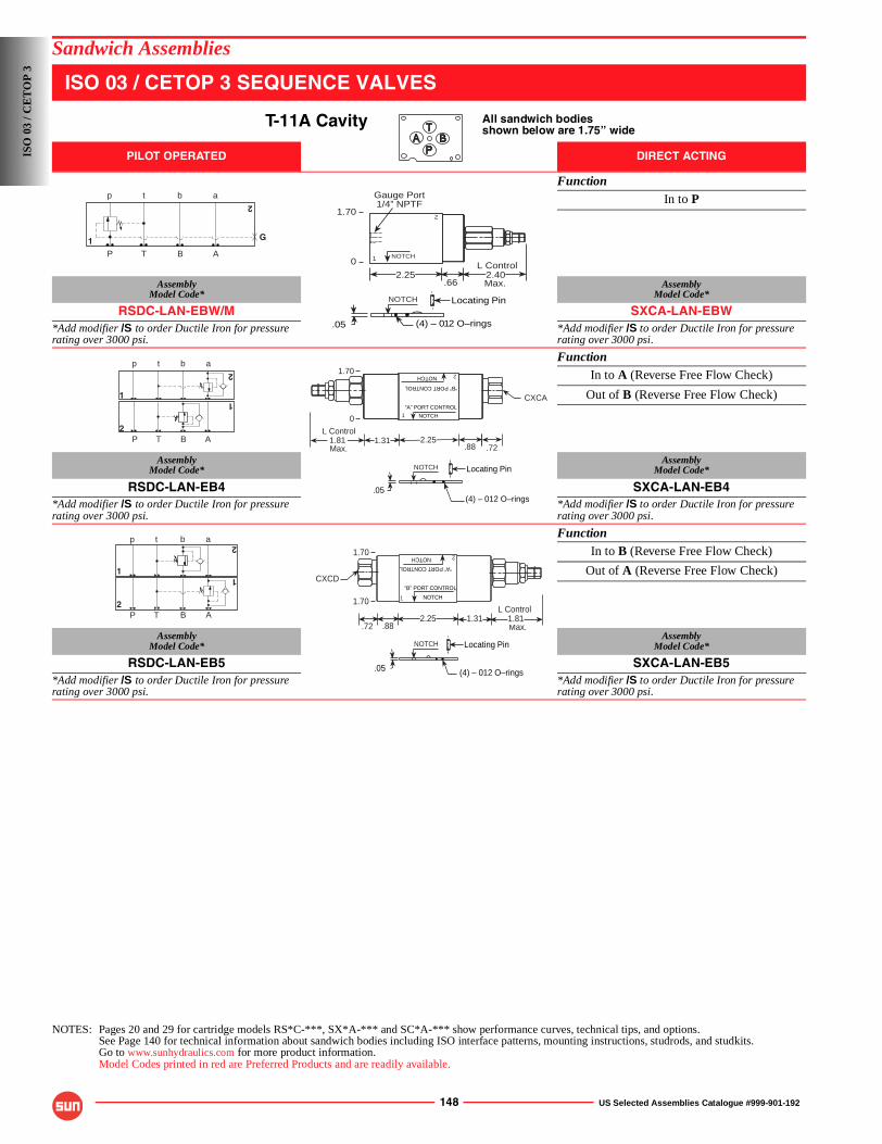
148 US Selected Assemblies Catalogue #999-901-192
Sandwich Assemblies
ISO 03 / CETOP 3 SEQUENCE VALVES
T-11A Cavity All sandwich bodiesshown below are 1.75” wide
PILOT OPERATED DIRECT ACTING
FunctionIn to P
AssemblyModel Code*
AssemblyModel Code*
RSDC-LAN-EBW/M SXCA-LAN-EBW*Add modifier /S to order Ductile Iron for pressure rating over 3000 psi.
*Add modifier /S to order Ductile Iron for pressure rating over 3000 psi.
FunctionIn to A (Reverse Free Flow Check)
Out of B (Reverse Free Flow Check)
AssemblyModel Code*
AssemblyModel Code*
RSDC-LAN-EB4 SXCA-LAN-EB4*Add modifier /S to order Ductile Iron for pressure rating over 3000 psi.
*Add modifier /S to order Ductile Iron for pressure rating over 3000 psi.
FunctionIn to B (Reverse Free Flow Check)
Out of A (Reverse Free Flow Check)
AssemblyModel Code*
AssemblyModel Code*
RSDC-LAN-EB5 SXCA-LAN-EB5*Add modifier /S to order Ductile Iron for pressure rating over 3000 psi.
*Add modifier /S to order Ductile Iron for pressure rating over 3000 psi.
NOTES: Pages 20 and 29 for cartridge models RS*C-***, SX*A-*** and SC*A-*** show performance curves, technical tips, and options.See Page 140 for technical information about sandwich bodies including ISO interface patterns, mounting instructions, studrods, and studkits.Go to www.sunhydraulics.com for more product information.Model Codes printed in red are Preferred Products and are readily available.
G
P T B A
p t b a
1
2
NOTCH
.66
L Control2.40Max.
2.25
.05 (4) – 012 O–rings
Gauge Port1/4” NPTF
1
21.70
NOTCH Locating Pin
0
P T B A
p t b a
2
2
1
1
1.31 2.25L Control
1.81 Max.
NOTCH
NOTCH
“B” PORT CONTROL
“A” PORT CONTROL1
2
.05(4) – 012 O–rings
.72
CXCA
.88
1.70
NOTCH Locating Pin
0
P T B A
p t b a
2
1
2
12
.882.25 1.31
L Control
Max.1.81
CXCD
.72
.05 (4) – 012 O–rings
1 NOTCH
“B” PORT CONTROLNOTCH
“A” PORT CONTROL
1.70
NOTCH Locating Pin
1.70
ISO
03
/ CE
TO
P 3
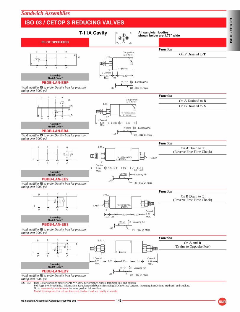
US Selected Assemblies Catalogue #999-901-192 149
Sandwich Assemblies
ISO 03 / CETOP 3 REDUCING VALVES
T-11A Cavity All sandwich bodiesshown below are 1.75” wide
PILOT OPERATED
FunctionOn P Drained to T
AssemblyModel Code*
PBDB-LAN-EBP*Add modifier /S to order Ductile Iron for pressure rating over 3000 psi.
Function
On A Drained to B
On B Drained to A
AssemblyModel Code*
PBDB-LAN-EBA*Add modifier /S to order Ductile Iron for pressure rating over 3000 psi.
FunctionOn A Drain to T
(Reverse Free Flow Check)
AssemblyModel Code*
PBDB-LAN-EB2*Add modifier /S to order Ductile Iron for pressure rating over 3000 psi.
FunctionOn B Drain to T
(Reverse Free Flow Check)
AssemblyModel Code*
PBDB-LAN-EB3*Add modifier /S to order Ductile Iron for pressure rating over 3000 psi.
FunctionOn A and B
(Drains to Opposite Port)
AssemblyModel Code*
PBDB-LAN-EBY*Add modifier /S to order Ductile Iron for pressure rating over 3000 psi.NOTES: Page 34 for cartridge model PB*B-*** show performance curves, technical tips, and options.
See Page 140 for technical information about sandwich bodies including ISO interface patterns, mounting instructions, studrods, and studkits.Go to www.sunhydraulics.com for more product information.Model Codes printed in red are Preferred Products and are readily available.
G
P T B A
p t b a
1
2
.662.251.81
Max.
L Control
1 NOTCH
Gauge Port1/4” NPTF
.05 (4) – 012 O–rings
1.70 2
NOTCH Locating Pin
0
GP T B A
p t b a
3
2
4
1 G
2
1
“A” PORT CONTROL
NOTCH
1.31 2.251.81 Max.
L Control
Gauge Port1/4” NPTF
.05(4) – 012 O–rings
1.70
NOTCH Locating Pin
0
p t b a
P T B A
1
.88 .721.31 2.25
1“A” PORT CONTROL
NOTCH
2.40 Max.
L Control
CXDA
(4) – 012 O–rings.05
1.70 2
NOTCH Locating Pin
0
P T B A
p t b a
1
.72 .88
NOTCH1
2.25 1.31
“B” PORT CONTROL
1.81 Max.
L Control
CXDA
.05(4) – 012 O–rings
1.70 2
NOTCH Locating Pin
0
P T B A
p t b a
1
2
1.31 2.25 1.31 1.81 Max.
L Control1.81 Max.
L Control
NOTCH1
2
(4) – 012 O–rings.05
1.70
NOTCH Locating Pin
0
ISO
03
/ CE
TO
P 3
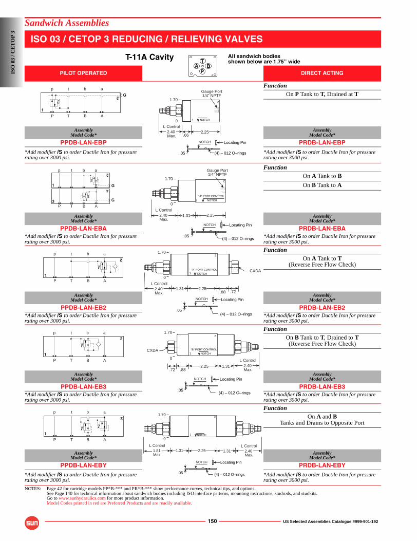
150 US Selected Assemblies Catalogue #999-901-192
Sandwich Assemblies
ISO 03 / CETOP 3 REDUCING / RELIEVING VALVES
T-11A Cavity All sandwich bodiesshown below are 1.75” wide
PILOT OPERATED DIRECT ACTING
FunctionOn P Tank to T, Drained at T
AssemblyModel Code*
AssemblyModel Code*
PPDB-LAN-EBP PRDB-LAN-EBP
*Add modifier /S to order Ductile Iron for pressure rating over 3000 psi.
*Add modifier /S to order Ductile Iron for pressure rating over 3000 psi.
FunctionOn A Tank to B
On B Tank to A
AssemblyModel Code*
AssemblyModel Code*
PPDB-LAN-EBA PRDB-LAN-EBA*Add modifier /S to order Ductile Iron for pressure rating over 3000 psi.
*Add modifier /S to order Ductile Iron for pressure rating over 3000 psi.
FunctionOn A Tank to T
(Reverse Free Flow Check)
AssemblyModel Code*
AssemblyModel Code*
PPDB-LAN-EB2 PRDB-LAN-EB2*Add modifier /S to order Ductile Iron for pressure rating over 3000 psi.
*Add modifier /S to order Ductile Iron for pressure rating over 3000 psi.
FunctionOn B Tank to T, Drained to T(Reverse Free Flow Check)
AssemblyModel Code*
AssemblyModel Code*
PPDB-LAN-EB3 PRDB-LAN-EB3*Add modifier /S to order Ductile Iron for pressure rating over 3000 psi.
*Add modifier /S to order Ductile Iron for pressure rating over 3000 psi.
FunctionOn A and B
Tanks and Drains to Opposite Port
AssemblyModel Code*
AssemblyModel Code*
PPDB-LAN-EBY PRDB-LAN-EBY*Add modifier /S to order Ductile Iron for pressure rating over 3000 psi.
*Add modifier /S to order Ductile Iron for pressure rating over 3000 psi.
NOTES: Page 42 for cartridge models PP*B-*** and PR*B-*** show performance curves, technical tips, and options.See Page 140 for technical information about sandwich bodies including ISO interface patterns, mounting instructions, studrods, and studkits.Go to www.sunhydraulics.com for more product information.Model Codes printed in red are Preferred Products and are readily available.
G
P T B A
p t b a
1
2
.662.252.40
Max.
L Control
1 NOTCH
Gauge Port1/4” NPTF
.05 (4) – 012 O–rings
1.70 2
NOTCH Locating Pin
0
GP T B A
p t b a
3
2
4
1 G
2
1
“A” PORT CONTROL
NOTCH
1.31 2.252.40 Max.
L Control
Gauge Port1/4” NPTF
.05(4) – 012 O–rings
1.70
NOTCH Locating Pin
0
P T B A
p t b a
12
.88 .721.31 2.25
1“A” PORT CONTROL
NOTCH
2.40 Max.
L Control
CXDA
(4) – 012 O–rings.05
1.70 2
NOTCH Locating Pin
0
P T B A
p t b a
1
2
.72 .88
NOTCH1
2.25 1.31
“B” PORT CONTROL
2.40 Max.
L Control
CXDA
.05(4) – 012 O–rings
1.70 2
NOTCH Locating Pin
0
P T B A
p t b a
1
2
1.31 2.25 1.31 2.40 Max.
L Control1.81 Max.
L Control
NOTCH1
2
(4) – 012 O–rings.05
1.70
NOTCH Locating Pin
0
ISO
03
/ CE
TO
P 3
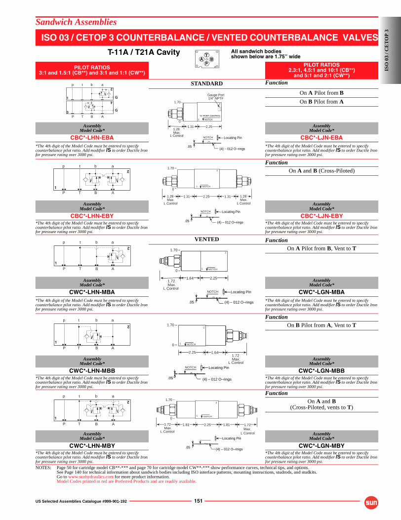
US Selected Assemblies Catalogue #999-901-192 151
Sandwich Assemblies
ISO 03 / CETOP 3 COUNTERBALANCE / VENTED COUNTERBALANCE VALVES
T-11A / T21A Cavity All sandwich bodiesshown below are 1.75” wide
PILOT RATIOS3:1 and 1.5:1 (CB**) and 3:1 and 1:1 (CW**)
PILOT RATIOS2.3:1, 4.5:1 and 10:1 (CB**)
and 5:1 and 2:1 (CW**)
STANDARD Function
On A Pilot from B
On B Pilot from A
AssemblyModel Code*
AssemblyModel Code*
CBC*-LHN-EBA CBC*-LJN-EBA*The 4th digit of the Model Code must be entered to specify counterbalance pilot ratio. Add modifier /S to order Ductile Iron for pressure rating over 3000 psi.
*The 4th digit of the Model Code must be entered to specify counterbalance pilot ratio. Add modifier /S to order Ductile Iron for pressure rating over 3000 psi.
FunctionOn A and B (Cross-Piloted)
AssemblyModel Code*
AssemblyModel Code*
CBC*-LHN-EBY CBC*-LJN-EBY*The 4th digit of the Model Code must be entered to specify counterbalance pilot ratio. Add modifier /S to order Ductile Iron for pressure rating over 3000 psi.
*The 4th digit of the Model Code must be entered to specify counterbalance pilot ratio. Add modifier /S to order Ductile Iron for pressure rating over 3000 psi.
VENTED FunctionOn A Pilot from B, Vent to T
AssemblyModel Code*
AssemblyModel Code*
CWC*-LHN-MBA CWC*-LGN-MBA*The 4th digit of the Model Code must be entered to specify counterbalance pilot ratio. Add modifier /S to order Ductile Iron for pressure rating over 3000 psi.
*The 4th digit of the Model Code must be entered to specify counterbalance pilot ratio. Add modifier /S to order Ductile Iron for pressure rating over 3000 psi.
FunctionOn B Pilot from A, Vent to T
AssemblyModel Code*
AssemblyModel Code*
CWC*-LHN-MBB CWC*-LGN-MBB*The 4th digit of the Model Code must be entered to specify counterbalance pilot ratio. Add modifier /S to order Ductile Iron for pressure rating over 3000 psi.
*The 4th digit of the Model Code must be entered to specify counterbalance pilot ratio. Add modifier /S to order Ductile Iron for pressure rating over 3000 psi.
FunctionOn A and B
(Cross-Piloted, vents to T)
AssemblyModel Code*
AssemblyModel Code*
CWC*-LHN-MBY CWC*-LGN-MBY*The 4th digit of the Model Code must be entered to specify counterbalance pilot ratio. Add modifier /S to order Ductile Iron for pressure rating over 3000 psi.
*The 4th digit of the Model Code must be entered to specify counterbalance pilot ratio. Add modifier /S to order Ductile Iron for pressure rating over 3000 psi.
NOTES: Page 50 for cartridge model CB**-*** and page 70 for cartridge model CW**-*** show performance curves, technical tips, and options.See Page 140 for technical information about sandwich bodies including ISO interface patterns, mounting instructions, studrods, and studkits.Go to www.sunhydraulics.com for more product information.Model Codes printed in red are Preferred Products and are readily available.
G
P T B A
p t b a
3
2
4
1 GGauge Port1/4” NPTF
2
1
“A” PORT CONTROL
NOTCH
(4) – 012 O–rings.05
1.31 2.251.28 Max.
L Control
1.70
NOTCH Locating Pin
0
P T B A
p t b a
1
2
1.31 2.25 1.28 Max.
L Control
1.311.28 Max.
L Control
(4) – 012 O–rings.05
NOTCH1
21.70
NOTCH Locating Pin
0
P T B A
p t b a
1
2
1.64 2.25
(4) – 012 O–rings.05
1.72 Max.
L Control
1.70
NOTCH12
NOTCH Locating Pin
0
P T B A
p t b a
1
2
(4) – 012 O–rings.05
2.25 1.641.72 Max.
L Control
NOTCH1
21.70
NOTCH Locating Pin
0
P T B A
p t b a
1
2
1.81 2.25 1.81
L Control Max.
L Control Max.
.05 (4) – 012 O–rings
NOTCH1
21.70
Locating Pin
0
1.721.72
ISO
03
/ CE
TO
P 3
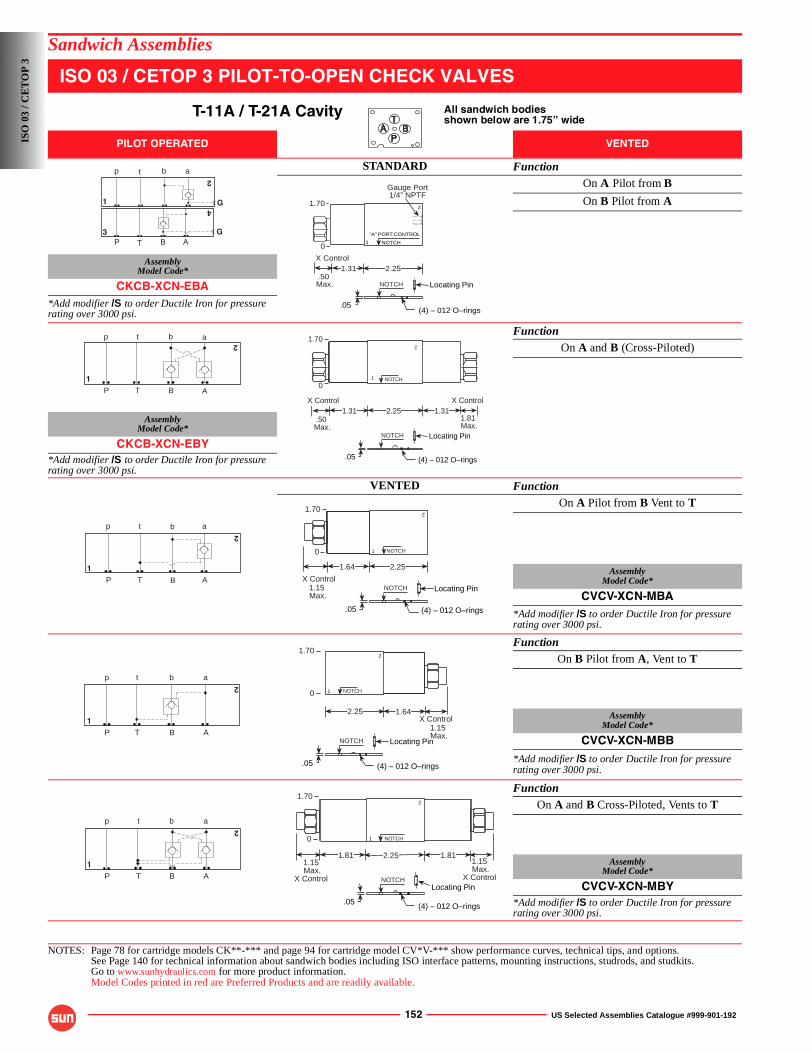
152 US Selected Assemblies Catalogue #999-901-192
Sandwich Assemblies
ISO 03 / CETOP 3 PILOT-TO-OPEN CHECK VALVES
T-11A / T-21A Cavity All sandwich bodiesshown below are 1.75” wide
PILOT OPERATED VENTED
STANDARD FunctionOn A Pilot from B
On B Pilot from A
AssemblyModel Code*
CKCB-XCN-EBA*Add modifier /S to order Ductile Iron for pressure rating over 3000 psi.
FunctionOn A and B (Cross-Piloted)
AssemblyModel Code*
CKCB-XCN-EBY*Add modifier /S to order Ductile Iron for pressure rating over 3000 psi.
VENTED FunctionOn A Pilot from B Vent to T
AssemblyModel Code*
CVCV-XCN-MBA*Add modifier /S to order Ductile Iron for pressure rating over 3000 psi.
FunctionOn B Pilot from A, Vent to T
AssemblyModel Code*
CVCV-XCN-MBB
*Add modifier /S to order Ductile Iron for pressure rating over 3000 psi.
FunctionOn A and B Cross-Piloted, Vents to T
AssemblyModel Code*
CVCV-XCN-MBY*Add modifier /S to order Ductile Iron for pressure rating over 3000 psi.
NOTES: Page 78 for cartridge models CK**-*** and page 94 for cartridge model CV*V-*** show performance curves, technical tips, and options.See Page 140 for technical information about sandwich bodies including ISO interface patterns, mounting instructions, studrods, and studkits.Go to www.sunhydraulics.com for more product information.Model Codes printed in red are Preferred Products and are readily available.
GP T B A
p t b a
3
2
4
1 G
1.31 2.25
(4) – 012 O–rings.05
.50 Max.
X Control
Gauge Port1/4” NPTF
1.70 2
1
“A” PORT CONTROL
NOTCH
NOTCH Locating Pin
0
P T B A
p t b a
1
2
1.31 2.251.81 Max.
X Control1.31
.50 Max.
X Control
(4) – 012 O–rings.05
1.70
NOTCH1
2
NOTCH Locating Pin
0
P T B A
p t b a
1
2
1.64 2.25
(4) – 012 O–rings.05
NOTCH
2
1.15 Max.
X Control
1.70
1
NOTCH Locating Pin
0
P T B A
p t b a
1
2
(4) – 012 O–rings.05
2.25 1.64
1.15 Max.
X Control
NOTCH1
21.70
NOTCH Locating Pin
0
P T B A
p t b a
1
2
1.81 2.25 1.811.15
X Control Max.
1.15
X Control Max.
.05 (4) – 012 O–rings
NOTCH1
21.70
NOTCHLocating Pin
0
ISO
03
/ CE
TO
P 3
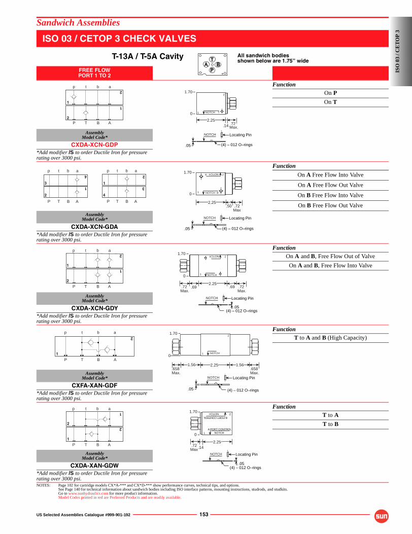
US Selected Assemblies Catalogue #999-901-192 153
Sandwich Assemblies
ISO 03 / CETOP 3 CHECK VALVES
T-13A / T-5A Cavity All sandwich bodiesshown below are 1.75” wide
FREE FLOWPORT 1 TO 2
FunctionOn P
On T
AssemblyModel Code*
CXDA-XCN-GDP*Add modifier /S to order Ductile Iron for pressure rating over 3000 psi.
Function
On A Free Flow Into Valve
On A Free Flow Out Valve
On B Free Flow Into Valve
On B Free Flow Out Valve
AssemblyModel Code*
CXDA-XCN-GDA*Add modifier /S to order Ductile Iron for pressure rating over 3000 psi.
FunctionOn A and B, Free Flow Out of Valve
On A and B, Free Flow Into Valve
AssemblyModel Code*
CXDA-XCN-GDY*Add modifier /S to order Ductile Iron for pressure rating over 3000 psi.
FunctionT to A and B (High Capacity)
AssemblyModel Code*
CXFA-XAN-GDF*Add modifier /S to order Ductile Iron for pressure rating over 3000 psi.
FunctionT to A
T to B
AssemblyModel Code*
CXDA-XAN-GDW*Add modifier /S to order Ductile Iron for pressure rating over 3000 psi.NOTES: Page 102 for cartridge models CX*A-*** and CX*D-*** show performance curves, technical tips, and options.
See Page 140 for technical information about sandwich bodies including ISO interface patterns, mounting instructions, studrods, and studkits.Go to www.sunhydraulics.com for more product information.Model Codes printed in red are Preferred Products and are readily available.
P T B A
p t b a
2
2
1
1
.142.25
2
.05 (4) – 012 O–rings
.72Max.
1 NOTCH T
1.70
NOTCH Locating Pin
0
P T B A
p t b a
2
3
4
1
P T B A
p t b a
4
3
1
2
.502.25
.05 (4) – 012 O–rings
.72Max
NOTCH1
2A
B
NOTCH1.70
NOTCH Locating Pin
0
P T B A
p t b a
22
11
.05(4) – 012 O–rings
2.25.69 .69.72
Max..72
Max.
1 NOTCH2NOTCH1.70
NOTCH Locating Pin
0
P T B A
p t b a
1
2
NOTCH1
2
2.25.658 Max.
.658 Max.
1.56 1.56
(4) – 012 O–rings.05
1.70
NOTCH Locating Pin
0
P T B A
p t b a
1
1
2
2
2
A PORT CONTROL
NOTCHB PORT CONTROL
.14.72Max
2.25
NOTCH1
.05(4) – 012 O–rings
1.70
NOTCH Locating Pin
0
ISO
03
/ CE
TO
P 3
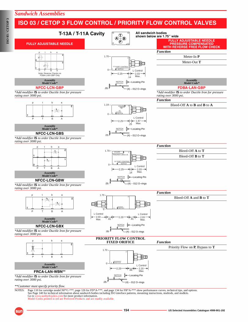
154 US Selected Assemblies Catalogue #999-901-192
Sandwich Assemblies
ISO 03 / CETOP 3 FLOW CONTROL / PRIORITY FLOW CONTROL VALVES
T-13A / T-11A Cavity All sandwich bodiesshown below are 1.75” wide
FULLY ADJUSTABLE NEEDLEFULLY ADJUSTABLE NEEDLEPRESSURE COMPENSATED
WITH REVERSE FREE FLOW CHECKFunction
Meter-In P
Meter-Out T
AssemblyModel Code*
AssemblyModel Code*
NFCC-LCN-GBP FDBA-LAN-GBP*Add modifier /S to order Ductile Iron for pressure rating over 3000 psi.
*Add modifier /S to order Ductile Iron for pressure rating over 3000 psi.
FunctionBleed-Off A to B and B to A
AssemblyModel Code*
NFCC-LCN-GBS*Add modifier /S to order Ductile Iron for pressure rating over 3000 psi.
FunctionBleed-Off A to T
Bleed-Off B to T
AssemblyModel Code*
NFCC-LCN-GBW*Add modifier /S to order Ductile Iron for pressure rating over 3000 psi.
FunctionBleed-Off A and B to T
AssemblyModel Code*
NFCC-LCN-GBX*Add modifier /S to order Ductile Iron for pressure rating over 3000 psi.
PRIORITY FLOW CONTROLFIXED ORIFICE Function
Priority Flow on P, Bypass to T
AssemblyModel Code*
FRCA-LAN-WBN***Add modifier /S to order Ductile Iron for pressure rating over 3000 psi.
**Customer must specify priority flow.NOTES: Page 110 for cartridge model NF*C-***, page 126 for FD*A-***, and page 134 for FR*A-*** show performance curves, technical tips, and options.
See Page 140 for technical information about sandwich bodies including ISO interface patterns, mounting instructions, studrods, and studkits.Go to www.sunhydraulics.com for more product information.Model Codes printed in red are Preferred Products and are readily available.
P T B A
p t b a
1
3
2
4
Note: Reverse Checks onFDBA-LAN-GBP Only
1.70
.142.25 2.03
Max.
L Control
(4) – 012 O–rings.05
“T” PORT CONTROL1 NOTCH
2
NOTCH Locating Pin
0
P T B A
p t b a
1
2
.252.25 1.97
Max.
L Control
(4) – 012 O–rings.05
NOTCH1A1
2NOTCHB1
1.19
NOTCH Locating Pin
0
P T B A
p t b a
2
2
1
1
.142.25 2.03
Max.
L Control
.05 (4) – 012 O–rings
1
2
NOTCH“A” PORT CONTROL
NOTCH
“B” PORT CONTROL
1.70
NOTCH Locating Pin
0
P T B A
p t b a
1
2
.812.25 2.03
Max.
L Control
.812.03 Max.
L Control
NOTCH1
2
.05 (4) – 012 O–rings
1.70
NOTCH Locating Pin
0
P T B A
p t b a
1
2
2.25 .66
NOTCH1
2
2.20 Max.
L Control
(4) – 012 O–rings.05
1.70
NOTCH Locating Pin
0
ISO
03
/ CE
TO
P 3
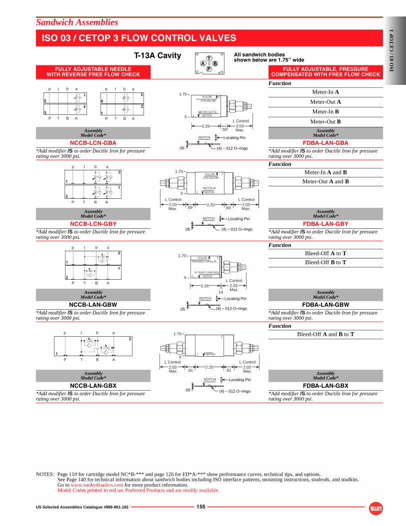
US Selected Assemblies Catalogue #999-901-192 155
Sandwich Assemblies
ISO 03 / CETOP 3 FLOW CONTROL VALVES
T-13A Cavity All sandwich bodiesshown below are 1.75” wide
FULLY ADJUSTABLE NEEDLEWITH REVERSE FREE FLOW CHECK
FULLY ADJUSTABLE, PRESSURE COMPENSATED WITH FREE FLOW CHECK
Function
Meter-In A
Meter-Out A
Meter-In B
Meter-Out B
AssemblyModel Code*
AssemblyModel Code*
NCCB-LCN-GBA FDBA-LAN-GBA*Add modifier /S to order Ductile Iron for pressure rating over 3000 psi.
*Add modifier /S to order Ductile Iron for pressure rating over 3000 psi.
FunctionMeter-In A and B
Meter-Out A and B
AssemblyModel Code*
AssemblyModel Code*
NCCB-LCN-GBY FDBA-LAN-GBY*Add modifier /S to order Ductile Iron for pressure rating over 3000 psi.
*Add modifier /S to order Ductile Iron for pressure rating over 3000 psi.
FunctionBleed-Off A to T
Bleed-Off B to T
AssemblyModel Code*
AssemblyModel Code*
NCCB-LAN-GBW FDBA-LAN-GBW*Add modifier /S to order Ductile Iron for pressure rating over 3000 psi.
*Add modifier /S to order Ductile Iron for pressure rating over 3000 psi.
FunctionBleed-Off A and B to T
AssemblyModel Code*
AssemblyModel Code*
NCCB-LAN-GBX FDBA-LAN-GBX*Add modifier /S to order Ductile Iron for pressure rating over 3000 psi.
*Add modifier /S to order Ductile Iron for pressure rating over 3000 psi.
NOTES: Page 110 for cartridge model NC*B-*** and page 126 for FD*A-*** show performance curves, technical tips, and options.See Page 140 for technical information about sandwich bodies including ISO interface patterns, mounting instructions, studrods, and studkits.Go to www.sunhydraulics.com for more product information.Model Codes printed in red are Preferred Products and are readily available.
P T B A
p t b a
3
1
4
2
P T B A
p t b a
1
2
3
4
.502.25 2.03
Max.
L Control
NOTCH1
2
METER OUT B
METER IN A
NOTCH
.05 (4) – 012 O–rings
1.70
NOTCH Locating Pin
0
P T B A
2
1
p t b a
2
1
.69.692.25 2.03
Max.
L Control2.03Max.
L Control
NOTCH1METER IN
NOTCHMETER OUT
2
.05 (4) – 012 O–rings
1.70
NOTCH Locating Pin
0
P T B A
p t b a
2
2
11
.14
2.25 2.03 Max.
L ControlNOTCH1
2
“A” PORT CONTROL
NOTCH“B” PORT CONTROL
.05 (4) – 012 O–rings
1.70
NOTCH Locating Pin
0
P T B A
p t b a
1
2
.81 .812.25 2.03
Max.
L Control2.03 Max.
L Control
NOTCH1
2
.05 (4) – 012 O–rings
1.70
NOTCH Locating Pin
0
ISO
03
/ CE
TO
P 3
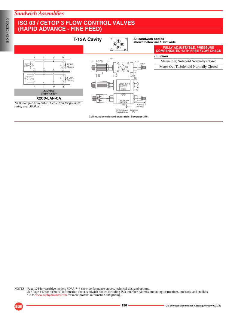
156 US Selected Assemblies Catalogue #999-901-192
Sandwich Assemblies
ISO 03 / CETOP 3 FLOW CONTROL VALVES(RAPID ADVANCE - FINE FEED)
T-13A Cavity All sandwich bodiesshown below are 1.75” wide
FULLY ADJUSTABLE, PRESSURECOMPENSATED WITH FREE FLOW CHECK
Function
Meter-In P, Solenoid Normally Closed
Meter-Out T, Solenoid Normally Closed
AssemblyModel Code*
X2CD-LAN-CA*Add modifier /S to order Ductile Iron for pressure rating over 3000 psi.
NOTES: Page 126 for cartridge models FD*A-*** show performance curves, technical tips, and options.See Page 140 for technical information about sandwich bodies including ISO interface patterns, mounting instructions, studrods, and studkits.Go to www.sunhydraulics.com for more product information and pricing.
FDBAShown
FDBAShown
a t p b
A T P B
p
b
t
a
METER-OUT T(NOTCH)
1.70
0.05
Coil must be selected separately. See page 248.
LocatingPin
-012 O-RingsTyp (4) Places
2.00 Max.
METER-IN P(NOTCH)
L Control
1.75
0
3.252.75.500
.692.91 Max
FDBA
ISO
03
/ CE
TO
P 3
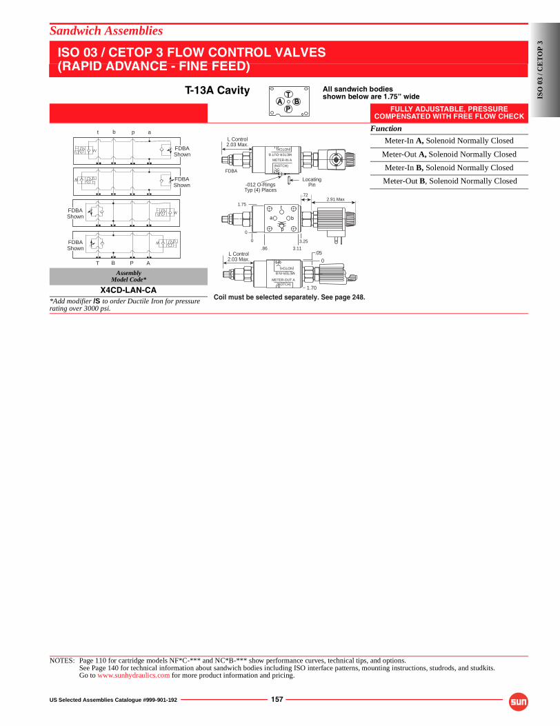
US Selected Assemblies Catalogue #999-901-192 157
Sandwich Assemblies
ISO 03 / CETOP 3 FLOW CONTROL VALVES(RAPID ADVANCE - FINE FEED)
T-13A Cavity All sandwich bodiesshown below are 1.75” wide
FULLY ADJUSTABLE, PRESSURECOMPENSATED WITH FREE FLOW CHECK
Function
Meter-In A, Solenoid Normally Closed
Meter-Out A, Solenoid Normally Closed
Meter-In B, Solenoid Normally Closed
AssemblyModel Code*
X4CD-LAN-CA*Add modifier /S to order Ductile Iron for pressure rating over 3000 psi.
NOTES: Page 110 for cartridge models NF*C-*** and NC*B-*** show performance curves, technical tips, and options.See Page 140 for technical information about sandwich bodies including ISO interface patterns, mounting instructions, studrods, and studkits.Go to www.sunhydraulics.com for more product information and pricing.
FDBAShown
FDBAShown
FDBAShown
FDBAShown
T APB
t apb
p
b
t
a
3.11.86
1.75
0
3.250
.722.91 Max
2.03 Max.
METER-OUT B
(NOTCH)
METER-IN A
(NOTCH)
LocatingPin-012 O-Rings
Typ (4) Places
L Control
2.03 Max.L Control
METER-OUT A(NOTCH)
METER-IN B(NOTCH)
0
.05
1.70
Coil must be selected separately. See page 248.
FDBA
ISO
03
/ CE
TO
P 3
Meter-Out B, Solenoid Normally Closed
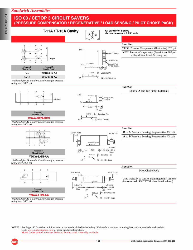
158 US Selected Assemblies Catalogue #999-901-192
Sandwich Assemblies
ISO 03 / CETOP 3 CIRCUIT SAVERS(PRESSURE COMPENSATOR / REGENERATIVE / LOAD SENSING / PILOT CHOKE PACK)
T-11A / T-13A Cavity All sandwich bodiesshown below are 1.75” wide
FunctionYFCG: Pressure Compensator (Restrictive), 200 psi
YFCJ: Pressure Compensator (Restrictive), 200 psiwith external Load-Sensing Port
ExternalShuttle Port
AssemblyModel Code*
None YFCG-XHN-AA
SAE-4 YFCJ-XHN-AA
*Add modifier /S to order Ductile Iron for pressure rating over 3000 psi.
FunctionShuttle A and B (Output External)
AssemblyModel Code*
CSAA-BXN-GBS*Add modifier /S to order Ductile Iron for pressure rating over 3000 psi.
FunctionB to A Pressure Sensing Regenerative Circuit
A to B Pressure Sensing Regenerative Circuit
AssemblyModel Code*
YDCA-LHN-AA*Add modifier /S to order Ductile Iron for pressure rating over 3000 psi.
FunctionPilot Choke Pack
(Used typically to control main stage shift time on pilot operated ISO/CETOP directional valves.)
AssemblyModel Code*
YNAA-LDN-AA*Add modifier /S to order Ductile Iron for pressure rating over 3000 psi.
NOTES: See Page 140 for technical information about sandwich bodies including ISO interface patterns, mounting instructions, studrods, and studkits.Go to www.sunhydraulics.com for more product information.Model Codes printed in red are Preferred Products and are readily available.
P T B A
p t b a
1
2
2
1
Output
NOTCH1
2
.75 .50
CSAB-*XN
LPDC-XHN
2.25
.05 (4) – 012 O–rings
2.50
NOTCH Locating Pin
0 Output PortYFCJ: SAE-4
P T B A
p t b a
1
2
Output
.252.25
.66 Max.
NOTCH1A1
2NOTCH
B1
.05 (4) – 012 O–rings
1.19
NOTCH Locating Pin
0
Output PortSAE-4
P T B A
p t b a
1
1
CODA-XEN
.50 .942.25 1.28
Max.
L Control1.31
NOTCH1
“B” PORT CONTROL
.05 (4) – 012 O–rings
CBCA-LHN1.70
NOTCH Locating Pin
0
P B A T
p b a t
.872.25 1.56
Max.
L Control
.38
NOTCH
PBBB-LAN
.05 (4) – 012 O–rings
NFBC-LCN
1.94Max.
1.18
NOTCH Locating Pin
L Control0
ISO
03
/ CE
TO
P 3
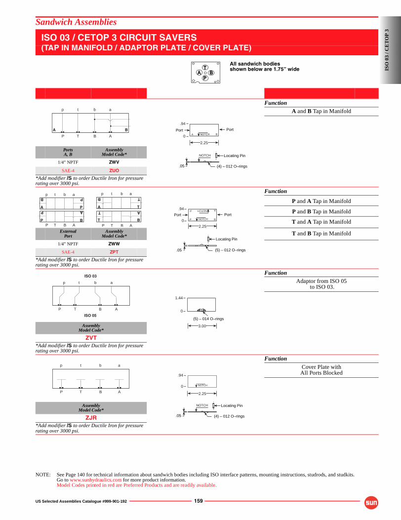
US Selected Assemblies Catalogue #999-901-192 159
Sandwich Assemblies
ISO 03 / CETOP 3 CIRCUIT SAVERS(TAP IN MANIFOLD / ADAPTOR PLATE / COVER PLATE)
All sandwich bodiesshown below are 1.75” wide
FunctionA and B Tap in Manifold
PortsA, B
AssemblyModel Code*
1/4” NPTF ZWV
SAE-4 ZUO
*Add modifier /S to order Ductile Iron for pressure rating over 3000 psi.
Function
P and A Tap in Manifold
P and B Tap in Manifold
T and A Tap in Manifold
ExternalPort
AssemblyModel Code* T and B Tap in Manifold
1/4” NPTF ZWW
SAE-4 ZPT
*Add modifier /S to order Ductile Iron for pressure rating over 3000 psi.
FunctionAdaptor from ISO 05
to ISO 03.
AssemblyModel Code*
ZVT*Add modifier /S to order Ductile Iron for pressure rating over 3000 psi.
Function
Cover Plate withAll Ports Blocked
AssemblyModel Code*
ZJR*Add modifier /S to order Ductile Iron for pressure rating over 3000 psi.
NOTE: See Page 140 for technical information about sandwich bodies including ISO interface patterns, mounting instructions, studrods, and studkits.Go to www.sunhydraulics.com for more product information.Model Codes printed in red are Preferred Products and are readily available.
P T B A
p t b a
A B
2.25
NOTCH
.05 (4) – 012 O–rings
.94
NOTCH Locating Pin
0 A B
PortPort
p t b a
A
P
B
A
P
P
P T B AP B
P T B AT
T A
B
p t b a
A
B T
T
2.25
NOTCHP B
NOTCH AP
.05 (5) – 012 O–rings
.94
Locating Pin
0
PortPort
ISO 03
ISO 05
P T B A
p t b a
(5) – 014 O–rings
3.00
1.44
0
P T B A
p t b a
.05 (4) – 012 O–rings
2.25
NOTCH
.94
NOTCH Locating Pin
0IS
O 0
3 / C
ET
OP
3
160 US Selected Assemblies Catalogue #999-901-192
Sandwich Assemblies
NOTES
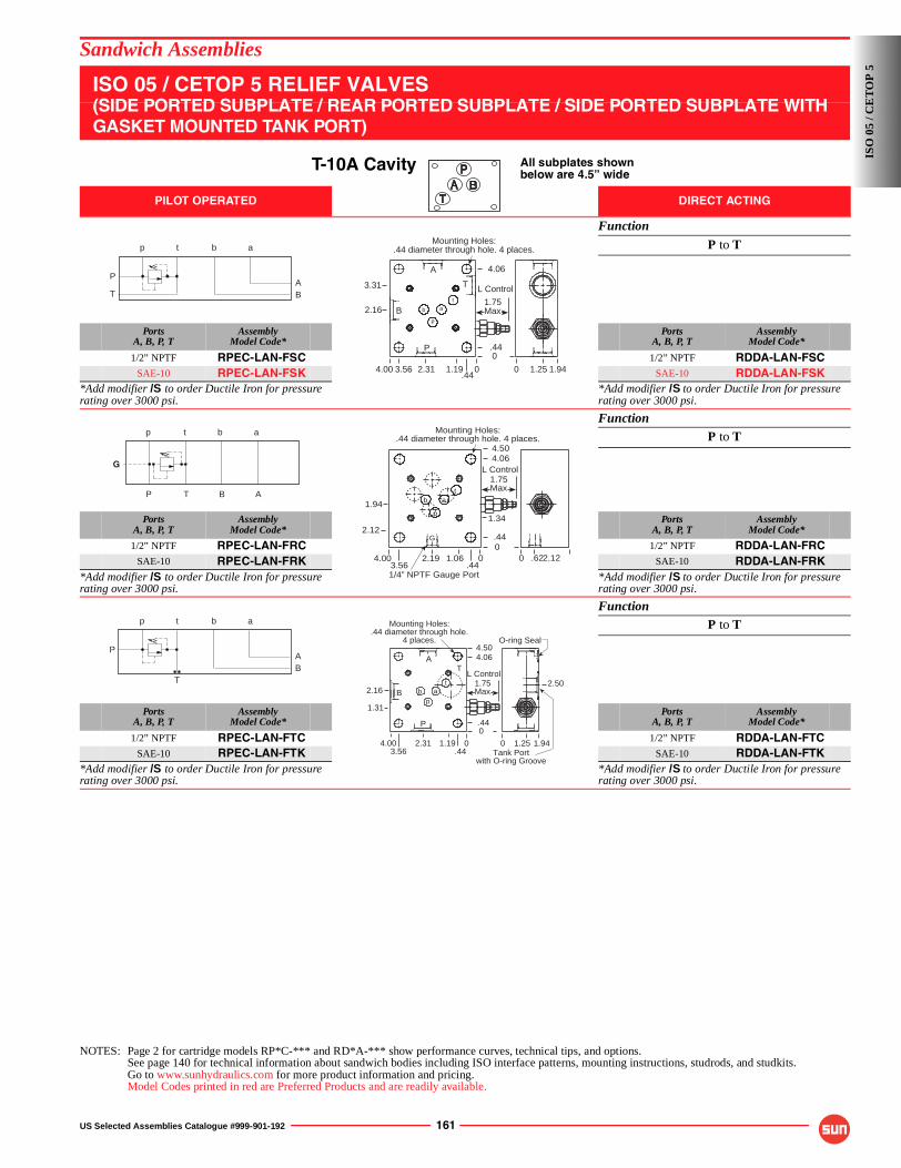
US Selected Assemblies Catalogue #999-901-192 161
Sandwich Assemblies
ISO 05 / CETOP 5 RELIEF VALVES(SIDE PORTED SUBPLATE / REAR PORTED SUBPLATE / SIDE PORTED SUBPLATE WITH GASKET MOUNTED TANK PORT)
T-10A Cavity All subplates shownbelow are 4.5” wide
PILOT OPERATED DIRECT ACTING
Function
P to T
PortsA, B, P, T
AssemblyModel Code*
PortsA, B, P, T
AssemblyModel Code*
1/2” NPTF RPEC-LAN-FSC 1/2” NPTF RDDA-LAN-FSCSAE-10 RPEC-LAN-FSK SAE-10 RDDA-LAN-FSK
*Add modifier /S to order Ductile Iron for pressure rating over 3000 psi.
*Add modifier /S to order Ductile Iron for pressure rating over 3000 psi.
FunctionP to T
PortsA, B, P, T
AssemblyModel Code*
PortsA, B, P, T
AssemblyModel Code*
1/2” NPTF RPEC-LAN-FRC 1/2” NPTF RDDA-LAN-FRCSAE-10 RPEC-LAN-FRK SAE-10 RDDA-LAN-FRK
*Add modifier /S to order Ductile Iron for pressure rating over 3000 psi.
*Add modifier /S to order Ductile Iron for pressure rating over 3000 psi.
FunctionP to T
PortsA, B, P, T
AssemblyModel Code*
PortsA, B, P, T
AssemblyModel Code*
1/2” NPTF RPEC-LAN-FTC 1/2” NPTF RDDA-LAN-FTCSAE-10 RPEC-LAN-FTK SAE-10 RDDA-LAN-FTK
*Add modifier /S to order Ductile Iron for pressure rating over 3000 psi.
*Add modifier /S to order Ductile Iron for pressure rating over 3000 psi.
NOTES: Page 2 for cartridge models RP*C-*** and RD*A-*** show performance curves, technical tips, and options.See page 140 for technical information about sandwich bodies including ISO interface patterns, mounting instructions, studrods, and studkits.Go to www.sunhydraulics.com for more product information and pricing.Model Codes printed in red are Preferred Products and are readily available.
P
T BA
p t b a
A
B
P
4.00 2.31 1.19
ta
p
b
3.56 0
0
2.16
3.31
4.06
.44
T
Mounting Holes:.44 diameter through hole. 4 places.
L Control
1.75Max
0 1.25 1.94.44
G
p t b a
P T B A
2.12G
4.00 2.19 1.06
ta
p
b
3.56 .440
0
1.94
0 .622.12
.44
1.34
4.064.50
1/4” NPTF Gauge Port
Mounting Holes:.44 diameter through hole. 4 places.
L Control1.75Max
P
TBA
p t b a
4.00 2.31.443.56
Mounting Holes:.44 diameter through hole.
4 places.
0
1.31
.44
4.064.50
ta
p
b
A
P
B
1.19 0 0 1.25 1.94
O-ring Seal
Tank Portwith O-ring Groove
L Control1.75Max2.16
T
2.50
ISO
05
/ CE
TO
P 5
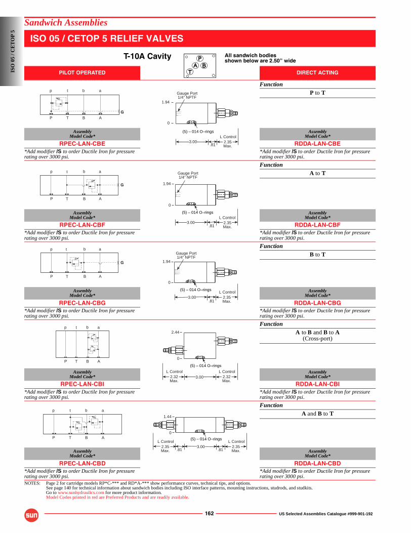
162 US Selected Assemblies Catalogue #999-901-192
Sandwich Assemblies
ISO 05 / CETOP 5 RELIEF VALVES
T-10A Cavity All sandwich bodiesshown below are 2.50” wide
PILOT OPERATED DIRECT ACTING
FunctionP to T
AssemblyModel Code*
AssemblyModel Code*
RPEC-LAN-CBE RDDA-LAN-CBE*Add modifier /S to order Ductile Iron for pressure rating over 3000 psi.
*Add modifier /S to order Ductile Iron for pressure rating over 3000 psi.
FunctionA to T
AssemblyModel Code*
AssemblyModel Code*
RPEC-LAN-CBF RDDA-LAN-CBF*Add modifier /S to order Ductile Iron for pressure rating over 3000 psi.
*Add modifier /S to order Ductile Iron for pressure rating over 3000 psi.
FunctionB to T
AssemblyModel Code*
AssemblyModel Code*
RPEC-LAN-CBG RDDA-LAN-CBG*Add modifier /S to order Ductile Iron for pressure rating over 3000 psi.
*Add modifier /S to order Ductile Iron for pressure rating over 3000 psi.
FunctionA to B and B to A
(Cross-port)
AssemblyModel Code*
AssemblyModel Code*
RPEC-LAN-CBI RDDA-LAN-CBI*Add modifier /S to order Ductile Iron for pressure rating over 3000 psi.
*Add modifier /S to order Ductile Iron for pressure rating over 3000 psi.
FunctionA and B to T
AssemblyModel Code*
AssemblyModel Code*
RPEC-LAN-CBD RDDA-LAN-CBD*Add modifier /S to order Ductile Iron for pressure rating over 3000 psi.
*Add modifier /S to order Ductile Iron for pressure rating over 3000 psi.
NOTES: Page 2 for cartridge models RP*C-*** and RD*A-*** show performance curves, technical tips, and options.See page 140 for technical information about sandwich bodies including ISO interface patterns, mounting instructions, studrods, and studkits.Go to www.sunhydraulics.com for more product information.Model Codes printed in red are Preferred Products and are readily available.
GP T B A
p t b a
1.94
Gauge Port1/4” NPTF
.813.00 2.35
Max.
L Control(5) – 014 O–rings
0
P T B A
G
p t b a
1.94
.81
(5) – 014 O–rings
2.35Max.
L Control3.00
Gauge Port1/4” NPTF
0
G
P T B A
p t b a
(5) – 014 O–rings
Gauge Port1/4” NPTF
.812.35Max.
L Control3.00
1.94
0
P T B A
p t b a
3.00
(5) – 014 O–rings
2.32Max.
L Control2.32Max.
L Control
2.44
0
P T B A
p t b a
(5) – 014 O–rings
1.44
.813.00 2.35
Max.
L Control
.812.35Max.
L Control
0
ISO
05
/ CE
TO
P 5
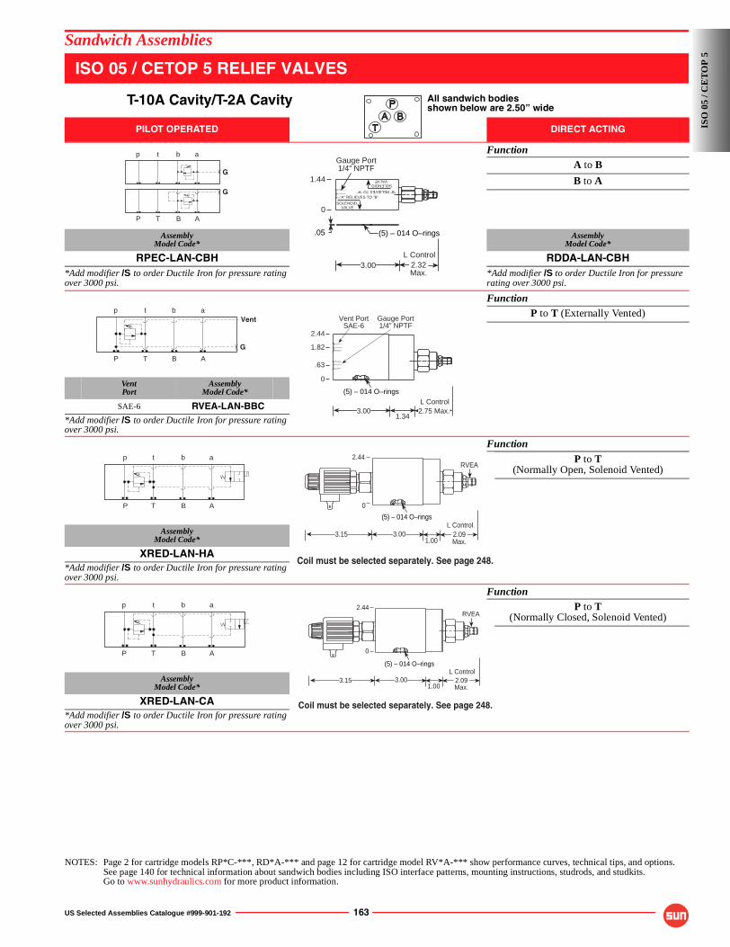
US Selected Assemblies Catalogue #999-901-192 163
Sandwich Assemblies
ISO 05 / CETOP 5 RELIEF VALVES
T-10A Cavity/T-2A Cavity All sandwich bodiesshown below are 2.50” wide
PILOT OPERATED DIRECT ACTING
FunctionA to B
B to A
AssemblyModel Code*
AssemblyModel Code*
RPEC-LAN-CBH RDDA-LAN-CBH*Add modifier /S to order Ductile Iron for pressure rating over 3000 psi.
*Add modifier /S to order Ductile Iron for pressure rating over 3000 psi.
FunctionP to T (Externally Vented)
VentPort
AssemblyModel Code*
SAE-6 RVEA-LAN-BBC*Add modifier /S to order Ductile Iron for pressure rating over 3000 psi.
Function
P to T(Normally Open, Solenoid Vented)
AssemblyModel Code*
XRED-LAN-HA*Add modifier /S to order Ductile Iron for pressure rating over 3000 psi.
FunctionP to T
(Normally Closed, Solenoid Vented)
AssemblyModel Code*
XRED-LAN-CA*Add modifier /S to order Ductile Iron for pressure rating over 3000 psi.
NOTES: Page 2 for cartridge models RP*C-***, RD*A-*** and page 12 for cartridge model RV*A-*** show performance curves, technical tips, and options.See page 140 for technical information about sandwich bodies including ISO interface patterns, mounting instructions, studrods, and studkits.Go to www.sunhydraulics.com for more product information.
G
p t b a
G
P T B A
Gauge Port1/4” NPTF
3.00
1.44
.05 (5) – 014 O–rings
2.32Max.
L Control
SOLENOIDVALVE
SOLENOIDVALVE
“B” RELIEVES TO “A”
“A” RELIEVES TO “B”
0
P T B A
p t b a
G
Vent
(5) – 014 O–rings
1.343.00
Vent PortSAE-6
2.44
2.75 Max.L Control
0
Gauge Port1/4” NPTF
1.82
.63
P T B A
p t b a
1.003.00
(5) – 014 O–rings
2.09Max.
L Control
RVEA2.44
3.15
0
Coil must be selected separately. See page 248.
P T B A
p t b a
1.003.00
(5) – 014 O–rings
2.09Max.
L Control
RVEA
3.15
2.44
0
Coil must be selected separately. See page 248.IS
O 0
5 / C
ET
OP
5
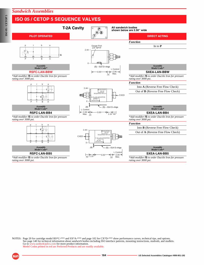
164 US Selected Assemblies Catalogue #999-901-192
Sandwich Assemblies
ISO 05 / CETOP 5 SEQUENCE VALVES
T-2A Cavity All sandwich bodiesshown below are 2.50” wide
PILOT OPERATED DIRECT ACTING
FunctionIn to P
AssemblyModel Code*
AssemblyModel Code*
RSFC-LAN-BBW SXEA-LAN-BBW*Add modifier /S to order Ductile Iron for pressure rating over 3000 psi.
*Add modifier /S to order Ductile Iron for pressure rating over 3000 psi.
FunctionInto A (Reverse Free Flow Check)
Out of B (Reverse Free Flow Check)
AssemblyModel Code*
AssemblyModel Code*
RSFC-LAN-BB4 SXEA-LAN-BB4*Add modifier /S to order Ductile Iron for pressure rating over 3000 psi.
*Add modifier /S to order Ductile Iron for pressure rating over 3000 psi.
FunctionInto B (Reverse Free Flow Check)
Out of A (Reverse Free Flow Check)
AssemblyModel Code*
AssemblyModel Code*
RSFC-LAN-BB5 SXEA-LAN-BB5*Add modifier /S to order Ductile Iron for pressure rating over 3000 psi.
*Add modifier /S to order Ductile Iron for pressure rating over 3000 psi.
NOTES: Page 20 for cartridge model RS*C-*** and SX*A-*** and page 102 for CX*D-*** show performance curves, technical tips, and options.See page 140 for technical information about sandwich bodies including ISO interface patterns, mounting instructions, studrods, and studkits.Go to www.sunhydraulics.com for more product information.Model Codes printed in red are Preferred Products and are readily available.
G
P T B A
p t b a Gauge Port1/4” NPTF
.313.00 2.06
Max.
L Control
2.44
(5) – 014 O–rings
0
P T B A
p t b a
(5) – 014 O–rings.05
.15
2.44
2.09Max.
L Control
1.10 .623.00
SEQUENCE INTO A
SOLENOIDVALVE
SOLENOIDVALVE
SEQUENCE OUT OF B
CXED
0
P T B A
p t b a
.05 (5) – 014 O–rings
.15.62 1.10
2.44
CXED
2.09Max.
L Control3.00
SEQUENCE INTO B
SOLENOIDVALVE
SOLENOIDVALVE
SEQUENCE OUT OF A
0
ISO
05
/ CE
TO
P 5
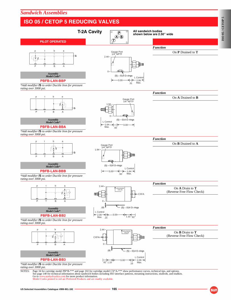
US Selected Assemblies Catalogue #999-901-192 165
Sandwich Assemblies
ISO 05 / CETOP 5 REDUCING VALVES
T-2A Cavity All sandwich bodiesshown below are 2.50” wide
PILOT OPERATED
FunctionOn P Drained to T
AssemblyModel Code*
PBFB-LAN-BBP*Add modifier /S to order Ductile Iron for pressure rating over 3000 psi.
FunctionOn A Drained to B
AssemblyModel Code*
PBFB-LAN-BBA*Add modifier /S to order Ductile Iron for pressure rating over 3000 psi.
FunctionOn B Drained to A
AssemblyModel Code*
PBFB-LAN-BBB*Add modifier /S to order Ductile Iron for pressure rating over 3000 psi.
FunctionOn A Drain to T
(Reverse Free Flow Check)
AssemblyModel Code*
PBFB-LAN-BB2*Add modifier /S to order Ductile Iron for pressure rating over 3000 psi.
Function
On B Drain to T(Reverse Free Flow Check)
AssemblyModel Code*
PBFB-LAN-BB3*Add modifier /S to order Ductile Iron for pressure rating over 3000 psi.NOTES: Page 34 for cartridge model PB*B-*** and page 102 for cartridge model CX*A-*** show performance curves, technical tips, and options.
See page 140 for technical information about sandwich bodies including ISO interface patterns, mounting instructions, studrods, and studkits.Go to www.sunhydraulics.com for more product information.Model Codes printed in red are Preferred Products and are readily available.
G
P T B A
p t b a Gauge Port1/4” NPTF
(5) – 014 O–rings
.312.06Max.
L Control3.00
2.44
0
P T B A
p t b a
G
(5) – 014 O–rings
Gauge Port1/4” NPTF
1.94
.503.001.64
Max.
L Control
0
G
P T B A
p t b a
Gauge Port1/4” NPTF
(5) – 014 O–rings
.503.00
1.94
1.64Max.
L Control
p t b a
P T B A
CXFA
1.10 .62.153.00
2.44
.05 (5) – 014 O–rings
2.09 Max.
L Control
SOLENOIDVALVE
0
P T B A
p t b a
.15.62 1.10
CXFA
.05 (5) – 014 O–rings
2.09 Max.
L Control3.00
SOLENOIDVALVE
2.44
0
ISO
05
/ CE
TO
P 5
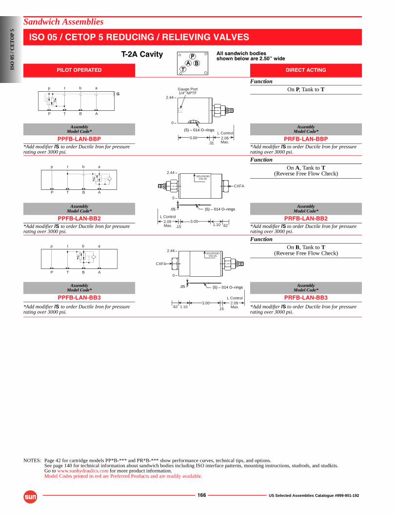
166 US Selected Assemblies Catalogue #999-901-192
Sandwich Assemblies
ISO 05 / CETOP 5 REDUCING / RELIEVING VALVES
T-2A Cavity All sandwich bodiesshown below are 2.50” wide
PILOT OPERATED DIRECT ACTING
FunctionOn P, Tank to T
AssemblyModel Code*
AssemblyModel Code*
PPFB-LAN-BBP PRFB-LAN-BBP*Add modifier /S to order Ductile Iron for pressure rating over 3000 psi.
*Add modifier /S to order Ductile Iron for pressure rating over 3000 psi.
FunctionOn A, Tank to T
(Reverse Free Flow Check)
AssemblyModel Code*
AssemblyModel Code*
PPFB-LAN-BB2 PRFB-LAN-BB2*Add modifier /S to order Ductile Iron for pressure rating over 3000 psi.
*Add modifier /S to order Ductile Iron for pressure rating over 3000 psi.
FunctionOn B, Tank to T
(Reverse Free Flow Check)
AssemblyModel Code*
AssemblyModel Code*
PPFB-LAN-BB3 PRFB-LAN-BB3
*Add modifier /S to order Ductile Iron for pressure rating over 3000 psi.
*Add modifier /S to order Ductile Iron for pressure rating over 3000 psi.
NOTES: Page 42 for cartridge models PP*B-*** and PR*B-*** show performance curves, technical tips, and options.See page 140 for technical information about sandwich bodies including ISO interface patterns, mounting instructions, studrods, and studkits.Go to www.sunhydraulics.com for more product information.Model Codes printed in red are Preferred Products and are readily available.
G
P T B A
p t b a Gauge Port1/4” NPTF
(5) – 014 O–rings
.312.06Max.
L Control3.00
2.44
0
P T B A
p t b a
CXFA
1.10 .62.153.00
2.44
.05 (5) – 014 O–rings
2.09 Max.
L Control
SOLENOIDVALVE
0
P T B A
p t b a
.15.62 1.10
CXFA
.05 (5) – 014 O–rings
2.09 Max.
L Control3.00
SOLENOIDVALVE
2.44
0
ISO
05
/ CE
TO
P 5
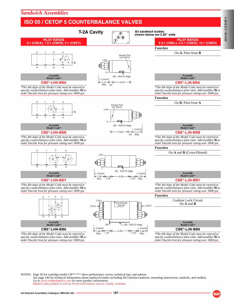
US Selected Assemblies Catalogue #999-901-192 167
Sandwich Assemblies
ISO 05 / CETOP 5 COUNTERBALANCE VALVES
T-2A Cavity All sandwich bodiesshown below are 2.50” wide
PILOT RATIOS3:1 (CBEA), 1.5:1 (CBEB), 2:1 (CBEY)
PILOT RATIOS2.3:1 (CBEL), 4.5:1 (CBEG), 10:1 (CBEH)
FunctionOn A, Pilot from B
AssemblyModel Code*
AssemblyModel Code*
CBE*-LHN-BBA CBE*-LJN-BBA*The 4th digit of the Model Code must be entered to specify counterbalance pilot ratio. Add modifier /S to order Ductile Iron for pressure rating over 3000 psi.
*The 4th digit of the Model Code must be entered to specify counterbalance pilot ratio. Add modifier /S to order Ductile Iron for pressure rating over 3000 psi.
Function
On B, Pilot from A
AssemblyModel Code*
AssemblyModel Code*
CBE*-LHN-BBB CBE*-LJN-BBB*The 4th digit of the Model Code must be entered to specify counterbalance pilot ratio. Add modifier /S to order Ductile Iron for pressure rating over 3000 psi.
*The 4th digit of the Model Code must be entered to specify counterbalance pilot ratio. Add modifier /S to order Ductile Iron for pressure rating over 3000 psi.
FunctionOn A and B (Cross-Piloted)
AssemblyModel Code*
AssemblyModel Code*
CBE*-LHN-BBY CBE*-LJN-BBY*The 4th digit of the Model Code must be entered to specify counterbalance pilot ratio. Add modifier /S to order Ductile Iron for pressure rating over 3000 psi.
*The 4th digit of the Model Code must be entered to specify counterbalance pilot ratio. Add modifier /S to order Ductile Iron for pressure rating over 3000 psi.
Function
Cushion Lock CircuitOn A and B
AssemblyModel Code*
AssemblyModel Code*
CBE*-LHN-BB8 CBE*-LJN-BB8*The 4th digit of the Model Code must be entered to specify counterbalance pilot ratio. Add modifier /S to order Ductile Iron for pressure rating over 3000 psi.
*The 4th digit of the Model Code must be entered to specify counterbalance pilot ratio. Add modifier /S to order Ductile Iron for pressure rating over 3000 psi.
NOTES: Page 50 for cartridge model CB**-*** show performance curves, technical tips, and options.See page 140 for technical information about sandwich bodies including ISO interface patterns, mounting instructions, studrods, and studkits.Go to www.sunhydraulics.com for more product information.Model Codes printed in red are Preferred Products and are readily available.
P T B A
p t b a
G
(5) – 014 O–rings
3.00.50
1.21 Max.
L Control
Gauge Port1/4” NPTF
1.94
0
G
P T B A
p t b a
(5) – 014 O–rings
.503.00
1.94
Gauge Port1/4” NPTF
1.21 Max.
L Control
0
P T B A
p t b a
(5) – 014 O–rings
1.061.06
1.94
1.69Max.
L Control3.00 1.69
Max.
L Control
0
P T B A
p t b a
CXFCCXFC
3.00
.05 (5) – 014 O–rings
1.66Max.
L Control
1.261.261.66 Max.
L Control
SOLENOIDVALVE
2.94
0
ISO
05
/ CE
TO
P 5
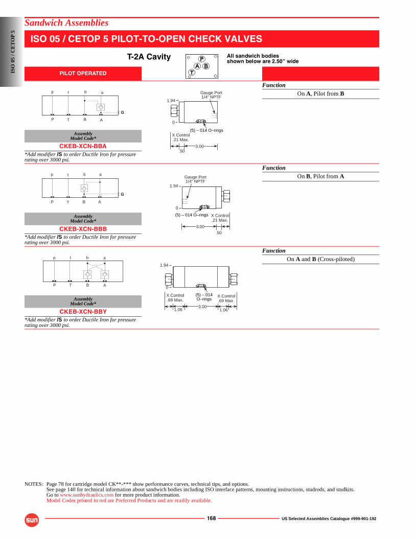
168 US Selected Assemblies Catalogue #999-901-192
Sandwich Assemblies
ISO 05 / CETOP 5 PILOT-TO-OPEN CHECK VALVES
T-2A Cavity All sandwich bodiesshown below are 2.50” wide
PILOT OPERATED
FunctionOn A, Pilot from B
AssemblyModel Code*
CKEB-XCN-BBA*Add modifier /S to order Ductile Iron for pressure rating over 3000 psi.
FunctionOn B, Pilot from A
AssemblyModel Code*
CKEB-XCN-BBB*Add modifier /S to order Ductile Iron for pressure rating over 3000 psi.
FunctionOn A and B (Cross-piloted)
AssemblyModel Code*
CKEB-XCN-BBY*Add modifier /S to order Ductile Iron for pressure rating over 3000 psi.
NOTES: Page 78 for cartridge model CK**-*** show performance curves, technical tips, and options.See page 140 for technical information about sandwich bodies including ISO interface patterns, mounting instructions, studrods, and studkits.Go to www.sunhydraulics.com for more product information.Model Codes printed in red are Preferred Products and are readily available.
P T B A
p t b a
G
(5) – 014 O–rings
.50
.21 Max.X Control
3.00
1.94
Gauge Port1/4” NPTF
0
G
P T B A
p t b a
1.94
(5) – 014 O–rings
.503.00
Gauge Port1/4” NPTF
0
.21 Max.X Control
P T B A
p t b a
1.061.063.00
(5) – 014O–rings
1.94
0
.69 Max.X Control
.69 Max.X Control
ISO
05
/ CE
TO
P 5
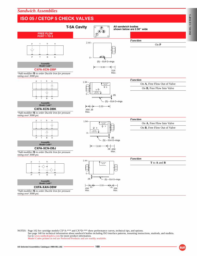
US Selected Assemblies Catalogue #999-901-192 169
Sandwich Assemblies
ISO 05 / CETOP 5 CHECK VALVES
T-5A Cavity All sandwich bodiesshown below are 2.50” wide
FREE FLOWPORT 1 TO 2
FunctionOn P
AssemblyModel Code*
CXFA-XCN-DBP*Add modifier /S to order Ductile Iron for pressure rating over 3000 psi.
FunctionOn A, Free Flow Out of Valve
On B, Free Flow Into Valve
AssemblyModel Code*
CXFA-XCN-DBK*Add modifier /S to order Ductile Iron for pressure rating over 3000 psi.
FunctionOn A, Free Flow Into Valve
On B, Free Flow Out of Valve
AssemblyModel Code*
CXFA-XCN-DBJ*Add modifier /S to order Ductile Iron for pressure rating over 3000 psi.
FunctionT to A and B
AssemblyModel Code*
CXFA-XAN-DBW*Add modifier /S to order Ductile Iron for pressure rating over 3000 psi.
NOTES: Page 102 for cartridge models CX*A-*** and CX*D-*** show performance curves, technical tips, and options.See page 140 for technical information about sandwich bodies including ISO interface patterns, mounting instructions, studrods, and studkits.Go to www.sunhydraulics.com for more product information.Model Codes printed in red are Preferred Products and are readily available.
P T B A
p t b a 2.44
(5) – 014 O–rings
.518 Max.
3.00
0
P T B A
p t b a 1.94
.38
3.00
.658 Max.
(5) – 014 O–rings
.05
SOLENOIDVALVE
SOLENOIDVALVE
0
A
B
P T B A
p t b a
.38
1.94
3.00.658Max.
(5) – 014 O–rings.05
SOLENOIDVALVE
SOLENOIDVALVE
0
AB
P T B A
p t b a
.81.81
2.44
(5) – 014 O–rings.05
3.00
.658 Max.
.658 Max.
SOLENOIDVALVE
0
ISO
05
/ CE
TO
P 5
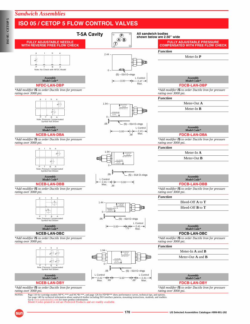
170 US Selected Assemblies Catalogue #999-901-192
Sandwich Assemblies
ISO 05 / CETOP 5 FLOW CONTROL VALVES
T-5A Cavity All sandwich bodiesshown below are 2.50” wide
FULLY ADJUSTABLE NEEDLEWITH REVERSE FREE FLOW CHECK
FULLY ADJUSTABLE PRESSURE COMPENSATED WITH FREE FLOW CHECK
Function
Meter-In P
AssemblyModel Code*
AssemblyModel Code*
NFDC-LAN-DBP FDCB-LAN-DBP*Add modifier /S to order Ductile Iron for pressure rating over 3000 psi.
*Add modifier /S to order Ductile Iron for pressure rating over 3000 psi.
FunctionMeter-Out A
Meter-In B
AssemblyModel Code*
AssemblyModel Code*
NCEB-LAN-DBA FDCB-LAN-DBA*Add modifier /S to order Ductile Iron for pressure rating over 3000 psi.
*Add modifier /S to order Ductile Iron for pressure rating over 3000 psi.
FunctionMeter-In A
Meter-Out B
AssemblyModel Code*
AssemblyModel Code*
NCEB-LAN-DBB FDCB-LAN-DBB*Add modifier /S to order Ductile Iron for pressure rating over 3000 psi.
*Add modifier /S to order Ductile Iron for pressure rating over 3000 psi.
Function
Bleed-Off A to T
Bleed-Off B to T
AssemblyModel Code*
AssemblyModel Code*
NCEB-LAN-DBC FDCB-LAN-DBC*Add modifier /S to order Ductile Iron for pressure rating over 3000 psi.
*Add modifier /S to order Ductile Iron for pressure rating over 3000 psi.
FunctionMeter-In A and B
Meter-Out A and B
AssemblyModel Code*
AssemblyModel Code*
NCEB-LAN-DBY FDCB-LAN-DBY*Add modifier /S to order Ductile Iron for pressure rating over 3000 psi.
*Add modifier /S to order Ductile Iron for pressure rating over 3000 psi.
NOTES: Page 110 for cartridge models NF*C-*** and NC*B-***, and page 126 for FD*B*** show performance curves, technical tips, and options.See page 140 for technical information about sandwich bodies including ISO interface patterns, mounting instructions, studrods, and studkits.Go to www.sunhydraulics.com for more product information.Model Codes printed in red are Preferred Products and are readily available.
P T B A
p t b a
Note: No Check with NFDC Model
(5) – 014 O–rings
2.44
2.47Max.
L Control3.00
0
P T B A
p t b a
Note: Pressure CompensatedSymbol Not Shown
.383.00 2.41
Max.
L Control
.05 (5) – 014 O–rings
METER-OUT A
SOLENOIDVALVE
SOLENOIDVALVE
METER-IN B
1.94
0
P T B A
p t b a
Note: Pressure CompensatedSymbol Not Shown
L Control
1.94
METER-OUT B
SOLENOIDVALVE
SOLENOIDVALVE
METER-IN A
.38
2.41Max.
3.00
(5) – 014 O–rings.05
0
p t b a
Note: Pressure CompensatedSymbol Not Shown
P T B A
1.44
.753.00 2.41
Max.
L Control
(5) – 014 O–rings.05
“A” PORT CONTROL
SOLENOIDVALVE
SOLENOIDVALVE
“B” PORT CONTROL
0
P T B A
p t b a
Note: Pressure CompensatedSymbol Not Shown
.05 (5) – 014 O–rings
.69 .693.00 2.41
Max.
L Control2.41Max.
L Control
METER-OUT
SOLENOIDVALVE
SOLENOIDVALVE
METER-IN
1.94
0
ISO
05
/ CE
TO
P 5
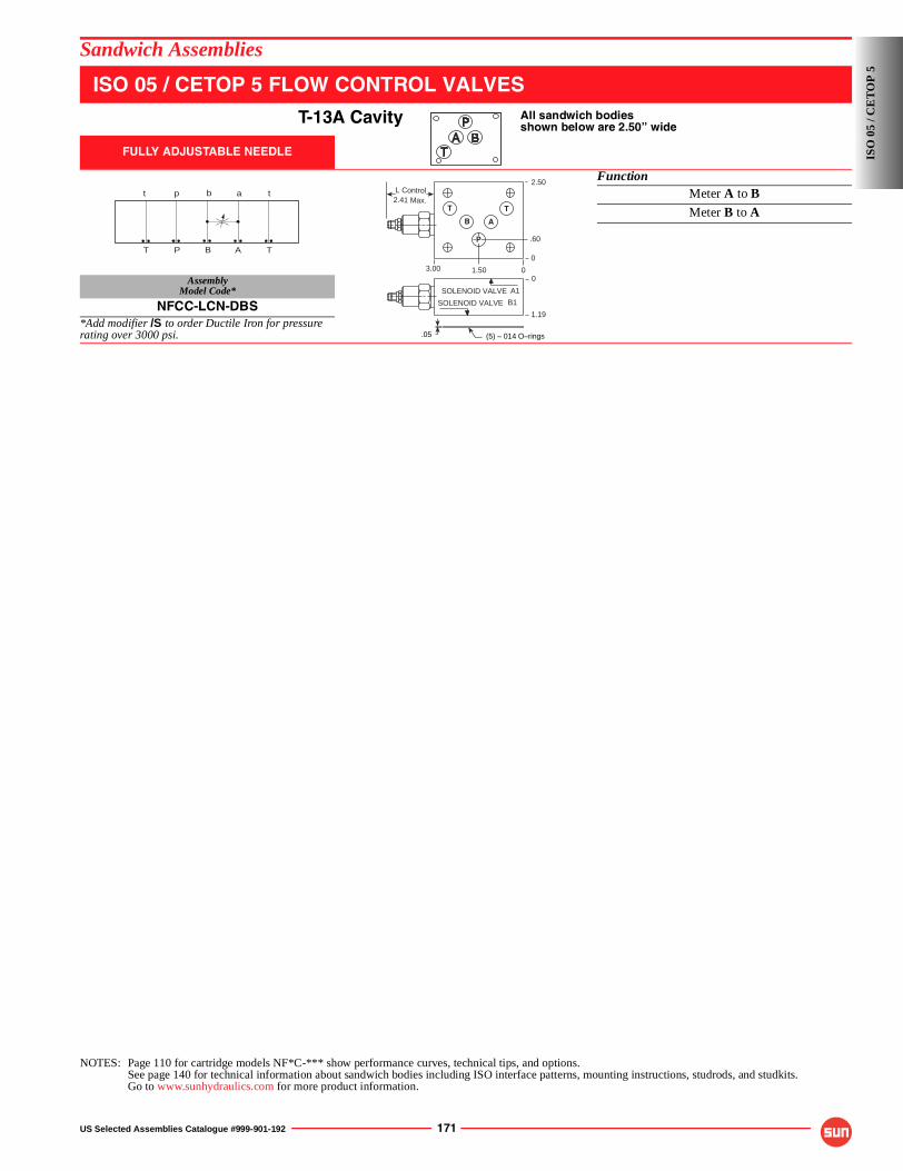
US Selected Assemblies Catalogue #999-901-192 171
Sandwich Assemblies
ISO 05 / CETOP 5 FLOW CONTROL VALVES
T-13A Cavity All sandwich bodiesshown below are 2.50” wide
FULLY ADJUSTABLE NEEDLE
FunctionMeter A to BMeter B to A
AssemblyModel Code*
NFCC-LCN-DBS*Add modifier /S to order Ductile Iron for pressure rating over 3000 psi.
NOTES: Page 110 for cartridge models NF*C-*** show performance curves, technical tips, and options.See page 140 for technical information about sandwich bodies including ISO interface patterns, mounting instructions, studrods, and studkits.Go to www.sunhydraulics.com for more product information.
A
a
T
t
P
p
T
t
B
b2.41 Max.L Control
0
0
2.50
.60
1.503.00
T T
P
AB
(5) – 014 O–rings.05
SOLENOID VALVE A1
SOLENOID VALVE B1
1.19
0
ISO
05
/ CE
TO
P 5
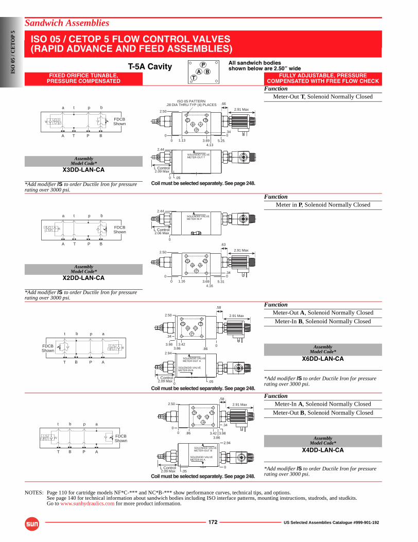
172 US Selected Assemblies Catalogue #999-901-192
Sandwich Assemblies
ISO 05 / CETOP 5 FLOW CONTROL VALVES(RAPID ADVANCE AND FEED ASSEMBLIES)
T-5A Cavity All sandwich bodiesshown below are 2.50” wide
FIXED ORIFICE TUNABLE,PRESSURE COMPENSATED
FULLY ADJUSTABLE, PRESSURECOMPENSATED WITH FREE FLOW CHECK
FunctionMeter-Out T, Solenoid Normally Closed
AssemblyModel Code*
X3DD-LAN-CA
*Add modifier /S to order Ductile Iron for pressure rating over 3000 psi.
FunctionMeter in P, Solenoid Normally Closed
AssemblyModel Code*
X2DD-LAN-CA
*Add modifier /S to order Ductile Iron for pressure rating over 3000 psi.
FunctionMeter-Out A, Solenoid Normally Closed
Meter-In B, Solenoid Normally Closed
AssemblyModel Code*
X6DD-LAN-CA
*Add modifier /S to order Ductile Iron for pressure rating over 3000 psi.
FunctionMeter-In A, Solenoid Normally Closed
Meter-Out B, Solenoid Normally Closed
AssemblyModel Code*
X4DD-LAN-CA
*Add modifier /S to order Ductile Iron for pressure rating over 3000 psi.
NOTES: Page 110 for cartridge models NF*C-*** and NC*B-*** show performance curves, technical tips, and options.See page 140 for technical information about sandwich bodies including ISO interface patterns, mounting instructions, studrods, and studkits.Go to www.sunhydraulics.com for more product information.
ta p b
TA P B
FDCBShown
4.13
2.50 2.91 Max
00 1.13 3.69 5.25
0.34
.66
TB
P
AT
ISO 05 PATTERN.28 DIA THRU-TYP (4) PLACES
.050
SOLENOID VALVEMETER-OUT T
L Control2.09 Max
2.44
Coil must be selected separately. See page 248.
ta p b
TA P B
FDCBShown
4.16
2.50 2.91 Max
00 1.16 3.69 5.31
0.34
.63
TB
P
AT
SOLENOID VALVEMETER-IN P
L Control2.06 Max
2.44
0
t apb
T APB
FDCBShown
L Control2.09 Max
SOLENOID VALVEMETER-OUT A
.05
2.94
0
SOLENOID VALVEMETER-IN B
2.91 Max
Coil must be selected separately. See page 248.
.863.86
2.50
3.98 3.42 0
.34
.58
TB
P
DT
t apb
T APB
FDCBShown
L Control2.09 Max
SOLENOID VALVEMETER-OUT B
.05
2.94
SOLENOID VALVEMETER-IN A
0
2.91 Max
TB
P
DT
.58
3.863.42
2.50
.86 3.98
.34
00
Coil must be selected separately. See page 248.
ISO
05
/ CE
TO
P 5
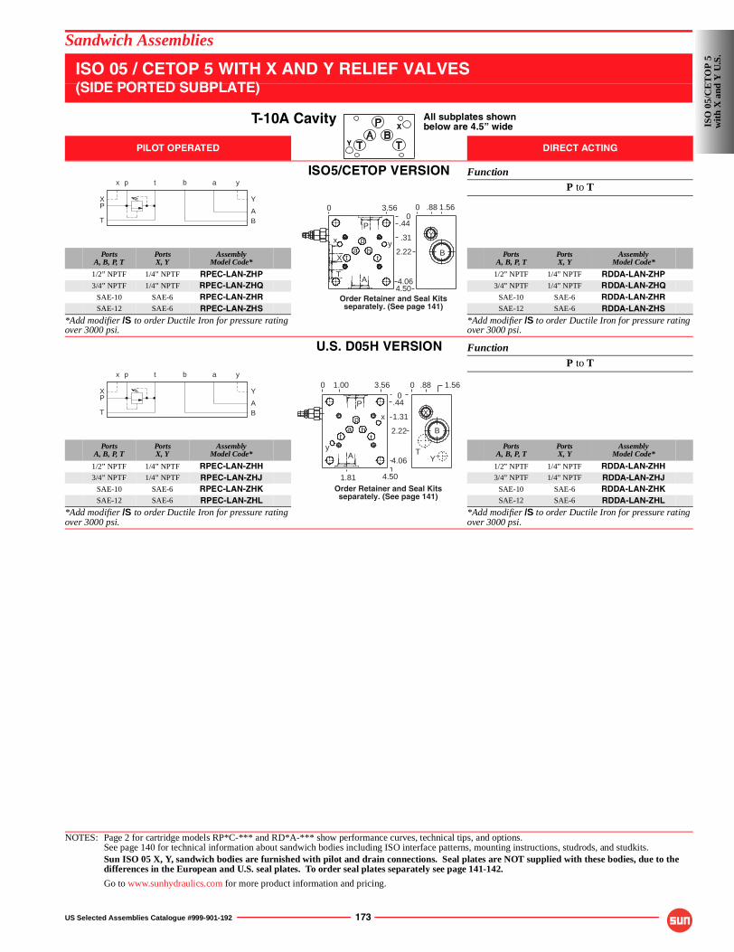
US Selected Assemblies Catalogue #999-901-192 173
Sandwich Assemblies
ISO 05 / CETOP 5 WITH X AND Y RELIEF VALVES(SIDE PORTED SUBPLATE)
T-10A Cavity All subplates shownbelow are 4.5” wide
PILOT OPERATED DIRECT ACTING
ISO5/CETOP VERSION FunctionP to T
PortsA, B, P, T
PortsX, Y
AssemblyModel Code*
PortsA, B, P, T
PortsX, Y
AssemblyModel Code*
1/2” NPTF 1/4” NPTF RPEC-LAN-ZHP 1/2” NPTF 1/4” NPTF RDDA-LAN-ZHP3/4” NPTF 1/4” NPTF RPEC-LAN-ZHQ 3/4” NPTF 1/4” NPTF RDDA-LAN-ZHQ
SAE-10 SAE-6 RPEC-LAN-ZHR SAE-10 SAE-6 RDDA-LAN-ZHRSAE-12 SAE-6 RPEC-LAN-ZHS SAE-12 SAE-6 RDDA-LAN-ZHS
*Add modifier /S to order Ductile Iron for pressure rating over 3000 psi.
*Add modifier /S to order Ductile Iron for pressure rating over 3000 psi.
U.S. D05H VERSION Function
P to T
PortsA, B, P, T
PortsX, Y
AssemblyModel Code*
PortsA, B, P, T
PortsX, Y
AssemblyModel Code*
1/2” NPTF 1/4” NPTF RPEC-LAN-ZHH 1/2” NPTF 1/4” NPTF RDDA-LAN-ZHH3/4” NPTF 1/4” NPTF RPEC-LAN-ZHJ 3/4” NPTF 1/4” NPTF RDDA-LAN-ZHJ
SAE-10 SAE-6 RPEC-LAN-ZHK SAE-10 SAE-6 RDDA-LAN-ZHKSAE-12 SAE-6 RPEC-LAN-ZHL SAE-12 SAE-6 RDDA-LAN-ZHL
*Add modifier /S to order Ductile Iron for pressure rating over 3000 psi.
*Add modifier /S to order Ductile Iron for pressure rating over 3000 psi.
NOTES: Page 2 for cartridge models RP*C-*** and RD*A-*** show performance curves, technical tips, and options.See page 140 for technical information about sandwich bodies including ISO interface patterns, mounting instructions, studrods, and studkits.Sun ISO 05 X, Y, sandwich bodies are furnished with pilot and drain connections. Seal plates are NOT supplied with these bodies, due to the differences in the European and U.S. seal plates. To order seal plates separately see page 141-142.
Go to www.sunhydraulics.com for more product information and pricing.
X
Y
P
T BA
p t b a
X
x
Y
y
0 .88 1.56
4.50
2.22 B
Yy
4.06
.31
.440
3.560
t tba
px
AT
X
P
Order Retainer and Seal Kitsseparately. (See page 141)
P
T BA
p t b a
X
x
Y
y
4.50
4.06
1.31
.440
3.560
2.22
0 .88 1.56
t tba
pB
X
T
1.00
1.81
A
x
y
P
Order Retainer and Seal Kitsseparately. (See page 141)
Y
ISO
05/
CE
TO
P 5
wit
h X
and
Y U
.S.
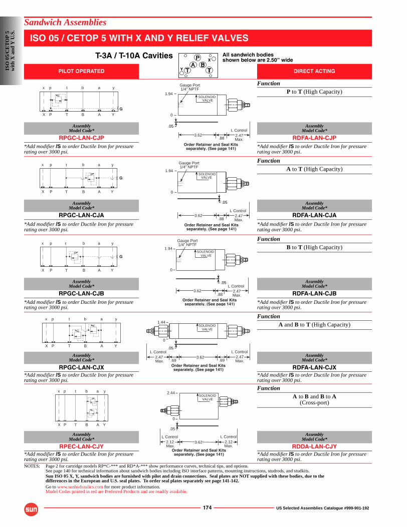
174 US Selected Assemblies Catalogue #999-901-192
Sandwich Assemblies
ISO 05 / CETOP 5 WITH X AND Y RELIEF VALVES
T-3A / T-10A Cavities All sandwich bodiesshown below are 2.50” wide
PILOT OPERATED DIRECT ACTING
FunctionP to T (High Capacity)
AssemblyModel Code*
AssemblyModel Code*
RPGC-LAN-CJP RDFA-LAN-CJP*Add modifier /S to order Ductile Iron for pressure rating over 3000 psi.
*Add modifier /S to order Ductile Iron for pressure rating over 3000 psi.
FunctionA to T (High Capacity)
AssemblyModel Code*
AssemblyModel Code*
RPGC-LAN-CJA RDFA-LAN-CJA*Add modifier /S to order Ductile Iron for pressure rating over 3000 psi.
*Add modifier /S to order Ductile Iron for pressure rating over 3000 psi.
FunctionB to T (High Capacity)
AssemblyModel Code*
AssemblyModel Code*
RPGC-LAN-CJB RDFA-LAN-CJB*Add modifier /S to order Ductile Iron for pressure rating over 3000 psi.
*Add modifier /S to order Ductile Iron for pressure rating over 3000 psi.
FunctionA and B to T (High Capacity)
AssemblyModel Code*
AssemblyModel Code*
RPGC-LAN-CJX RDFA-LAN-CJX*Add modifier /S to order Ductile Iron for pressure rating over 3000 psi.
*Add modifier /S to order Ductile Iron for pressure rating over 3000 psi.
FunctionA to B and B to A
(Cross-port)
AssemblyModel Code*
AssemblyModel Code*
RPEC-LAN-CJY RDDA-LAN-CJY*Add modifier /S to order Ductile Iron for pressure rating over 3000 psi.
*Add modifier /S to order Ductile Iron for pressure rating over 3000 psi.
NOTES: Page 2 for cartridge models RP*C-*** and RD*A-*** show performance curves, technical tips, and options.See page 140 for technical information about sandwich bodies including ISO interface patterns, mounting instructions, studrods, and studkits.Sun ISO 05 X, Y, sandwich bodies are furnished with pilot and drain connections. Seal plates are NOT supplied with these bodies, due to the differences in the European and U.S. seal plates. To order seal plates separately see page 141-142.Go to www.sunhydraulics.com for more product information.Model Codes printed in red are Preferred Products and are readily available.
X
Y
GP T B A
p t b a
X
x
Y
y
.883.62
Gauge Port1/4” NPTF
.05
1.94SOLENOID
VALVE
2.47Max.
L Control
0
Order Retainer and Seal Kitsseparately. (See page 141)
P T B A
G
p t b a
X
x
Y
y
.883.62 2.47
Max.
L Control
Gauge Port1/4” NPTF
.05
SOLENOIDVALVE
1.94
0
Order Retainer and Seal Kitsseparately. (See page 141)
G
P T B A
p t b a
X
x
Y
y
.883.62 2.47
Max.
L Control
Gauge Port1/4” NPTF
1.94
.05
SOLENOIDVALVE
0
Order Retainer and Seal Kitsseparately. (See page 141)
P T B A
p t b a
X
x
Y
y
.69.693.62 2.47
Max.
L Control2.47 Max.
L Control
1.44
.05
SOLENOIDVALVE
0
Order Retainer and Seal Kitsseparately. (See page 141)
P T B A
p t b a
X
x
Y
y 2.44
.05
3.622.12 Max.
L Control2.12Max.
L Control
SOLENOIDVALVE
0
Order Retainer and Seal Kitsseparately. (See page 141)
ISO
05/
CE
TO
P 5
wit
h X
and
Y U
.S.
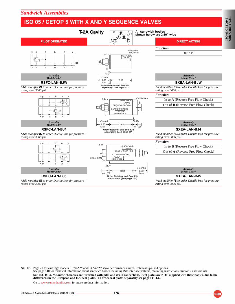
US Selected Assemblies Catalogue #999-901-192 175
Sandwich Assemblies
ISO 05 / CETOP 5 WITH X AND Y SEQUENCE VALVES
T-2A Cavity All sandwich bodiesshown below are 2.50” wide
PILOT OPERATED DIRECT ACTING
FunctionIn to P
AssemblyModel Code*
AssemblyModel Code*
RSFC-LAN-BJW SXEA-LAN-BJW*Add modifier /S to order Ductile Iron for pressure rating over 3000 psi.
*Add modifier /S to order Ductile Iron for pressure rating over 3000 psi.
FunctionIn to A (Reverse Free Flow Check)
Out of B (Reverse Free Flow Check)
AssemblyModel Code*
AssemblyModel Code*
RSFC-LAN-BJ4 SXEA-LAN-BJ4*Add modifier /S to order Ductile Iron for pressure rating over 3000 psi.
*Add modifier /S to order Ductile Iron for pressure rating over 3000 psi.
FunctionIn to B (Reverse Free Flow Check)
Out of A (Reverse Free Flow Check)
AssemblyModel Code*
AssemblyModel Code*
RSFC-LAN-BJ5 SXEA-LAN-BJ5*Add modifier /S to order Ductile Iron for pressure rating over 3000 psi.
*Add modifier /S to order Ductile Iron for pressure rating over 3000 psi.
NOTES: Page 20 for cartridge models RS*C-*** and SX*A-*** show performance curves, technical tips, and options.See page 140 for technical information about sandwich bodies including ISO interface patterns, mounting instructions, studrods, and studkits.Sun ISO 05 X, Y, sandwich bodies are furnished with pilot and drain connections. Seal plates are NOT supplied with these bodies, due to the differences in the European and U.S. seal plates. To order seal plates separately see page 141-142.
Go to www.sunhydraulics.com for more product information.
X
Y
G
P T B A
p t b a
X
x
Y
yGauge Port1/4” NPTF
.193.622.06
Max.
L Control
.05
VALVESOLENOID
2.44
0
Order Retainer and Seal Kitsseparately. (See page 141)
P T B A
p t b a
X
x
Y
yCXED-XAN
SOLENOID
SEQUENCE INTO A
VALVE
VALVE
SEQUENCE OUT B
SOLENOID
.05
1.93Max.
L Control
.78 .623.62
2.44
0
Order Retainer and Seal Kitsseparately. (See page 141)
p t b ax y
P T B AX Y
.62 .78
CXED-XAN
1.93 Max.
L Control3.62
SEQUENCE OUT ASEQUENCE INTO B
VALVESOLENOID
VALVESOLENOID
2.44
.05
0
Order Retainer and Seal Kitsseparately. (See page 141)
ISO
05/
CE
TO
P 5
wit
h X
and
Y U
.S.
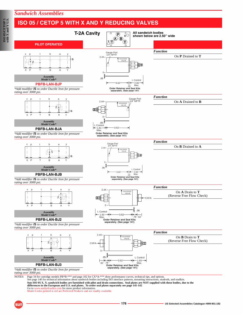
176 US Selected Assemblies Catalogue #999-901-192
Sandwich Assemblies
ISO 05 / CETOP 5 WITH X AND Y REDUCING VALVES
T-2A Cavity All sandwich bodiesshown below are 2.50” wide
PILOT OPERATED
FunctionOn P Drained to T
AssemblyModel Code*
PBFB-LAN-BJP*Add modifier /S to order Ductile Iron for pressure rating over 3000 psi.
FunctionOn A Drained to B
AssemblyModel Code*
PBFB-LAN-BJA*Add modifier /S to order Ductile Iron for pressure rating over 3000 psi.
FunctionOn B Drained to A
AssemblyModel Code*
PBFB-LAN-BJB*Add modifier /S to order Ductile Iron for pressure rating over 3000 psi.
Function
On A Drain to T(Reverse Free Flow Check)
AssemblyModel Code*
PBFB-LAN-BJ2*Add modifier /S to order Ductile Iron for pressure rating over 3000 psi.
FunctionOn B Drain to T
(Reverse Free Flow Check)
AssemblyModel Code*
PBFB-LAN-BJ3*Add modifier /S to order Ductile Iron for pressure rating over 3000 psi.NOTES: Page 34 for cartridge models PB*B-*** and page 102 for CX*A-*** show performance curves, technical tips, and options.
See page 140 for technical information about sandwich bodies including ISO interface patterns, mounting instructions, studrods, and studkits.Sun ISO 05 X, Y, sandwich bodies are furnished with pilot and drain connections. Seal plates are NOT supplied with these bodies, due to the differences in the European and U.S. seal plates. To order seal plates separately see page 141-142Go to www.sunhydraulics.com for more product information.Model Codes printed in red are Preferred Products and are readily available.
X
Y
G
P T B A
p t b a
X
x
Y
y
.193.62
Gauge Port1/4” NPTF
2.06Max.
L Control
2.44
.05
SOLENOIDVALVE
0
Order Retainer and Seal Kitsseparately. (See page 141)
P T B A
p t b a
G
X
x
Y
y
.05
2.44Gauge Port1/4” NPTF
SOLENOIDVALVE
3.621.81Max.
L Control
0
Order Retainer and Seal Kitsseparately. (See page 141)
G
P T B A
p t b a
X
x
Y
y
.193.62
Gauge Port1/4” NPTF
2.06Max.
L Control
2.44
.05
SOLENOIDVALVE
0
Order Retainer and Seal Kitsseparately. (See page 141)
p t b a
P T B AX
x
Y
y 2.44
CXFA
SOLENOIDVALVE
.05
3.621.93Max.
L Control
.78 .62
0
Order Retainer and Seal Kitsseparately. (See page 141)
P T B A
p t b a
X
x
Y
y
.05
.78.62
2.44
CXFA
SOLENOIDVALVE
3.62 1.93Max.
L Control
0
Order Retainer and Seal Kitsseparately. (See page 141)
ISO
05/
CE
TO
P 5
wit
h X
and
Y U
.S.
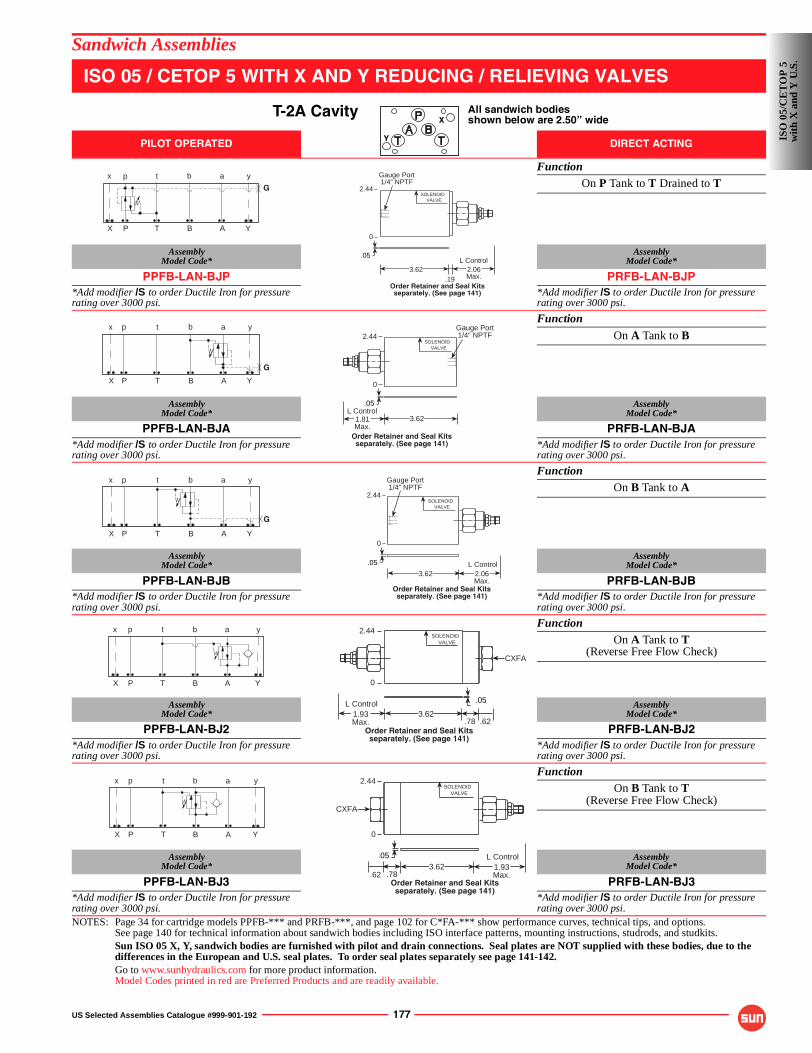
US Selected Assemblies Catalogue #999-901-192 177
Sandwich Assemblies
ISO 05 / CETOP 5 WITH X AND Y REDUCING / RELIEVING VALVES
T-2A Cavity All sandwich bodiesshown below are 2.50” wide
PILOT OPERATED DIRECT ACTING
FunctionOn P Tank to T Drained to T
AssemblyModel Code*
AssemblyModel Code*
PPFB-LAN-BJP PRFB-LAN-BJP*Add modifier /S to order Ductile Iron for pressure rating over 3000 psi.
*Add modifier /S to order Ductile Iron for pressure rating over 3000 psi.
Function
On A Tank to B
AssemblyModel Code*
AssemblyModel Code*
PPFB-LAN-BJA PRFB-LAN-BJA*Add modifier /S to order Ductile Iron for pressure rating over 3000 psi.
*Add modifier /S to order Ductile Iron for pressure rating over 3000 psi.
FunctionOn B Tank to A
AssemblyModel Code*
AssemblyModel Code*
PPFB-LAN-BJB PRFB-LAN-BJB*Add modifier /S to order Ductile Iron for pressure rating over 3000 psi.
*Add modifier /S to order Ductile Iron for pressure rating over 3000 psi.
FunctionOn A Tank to T
(Reverse Free Flow Check)
AssemblyModel Code*
AssemblyModel Code*
PPFB-LAN-BJ2 PRFB-LAN-BJ2*Add modifier /S to order Ductile Iron for pressure rating over 3000 psi.
*Add modifier /S to order Ductile Iron for pressure rating over 3000 psi.
FunctionOn B Tank to T
(Reverse Free Flow Check)
AssemblyModel Code*
AssemblyModel Code*
PPFB-LAN-BJ3 PRFB-LAN-BJ3*Add modifier /S to order Ductile Iron for pressure rating over 3000 psi.
*Add modifier /S to order Ductile Iron for pressure rating over 3000 psi.
NOTES: Page 34 for cartridge models PPFB-*** and PRFB-***, and page 102 for C*FA-*** show performance curves, technical tips, and options.See page 140 for technical information about sandwich bodies including ISO interface patterns, mounting instructions, studrods, and studkits.Sun ISO 05 X, Y, sandwich bodies are furnished with pilot and drain connections. Seal plates are NOT supplied with these bodies, due to the differences in the European and U.S. seal plates. To order seal plates separately see page 141-142.Go to www.sunhydraulics.com for more product information.Model Codes printed in red are Preferred Products and are readily available.
X
Y
G
P T B A
p t b a
X
x
Y
y
.193.62
Gauge Port1/4” NPTF
2.06Max.
L Control
2.44
.05
SOLENOIDVALVE
0
Order Retainer and Seal Kitsseparately. (See page 141)
P T B A
p t b a
G
X
x
Y
y
.05
2.44Gauge Port1/4” NPTF
SOLENOIDVALVE
3.621.81Max.
L Control
0
Order Retainer and Seal Kitsseparately. (See page 141)
P T B A
p t b a
G
X
x
Y
y
3.62
Gauge Port1/4” NPTF
2.44
.05
2.06Max.
L Control
SOLENOIDVALVE
0
Order Retainer and Seal Kitsseparately. (See page 141)
P T B A
p t b a
X
x
Y
y 2.44
CXFA
SOLENOIDVALVE
.05
3.621.93Max.
L Control
.78 .62
0
Order Retainer and Seal Kitsseparately. (See page 141)
P T B A
p t b a
X
x
Y
y
.05
.78.62
2.44
CXFA
SOLENOIDVALVE
3.62 1.93Max.
L Control
0
Order Retainer and Seal Kitsseparately. (See page 141)
ISO
05/
CE
TO
P 5
wit
h X
and
Y U
.S.
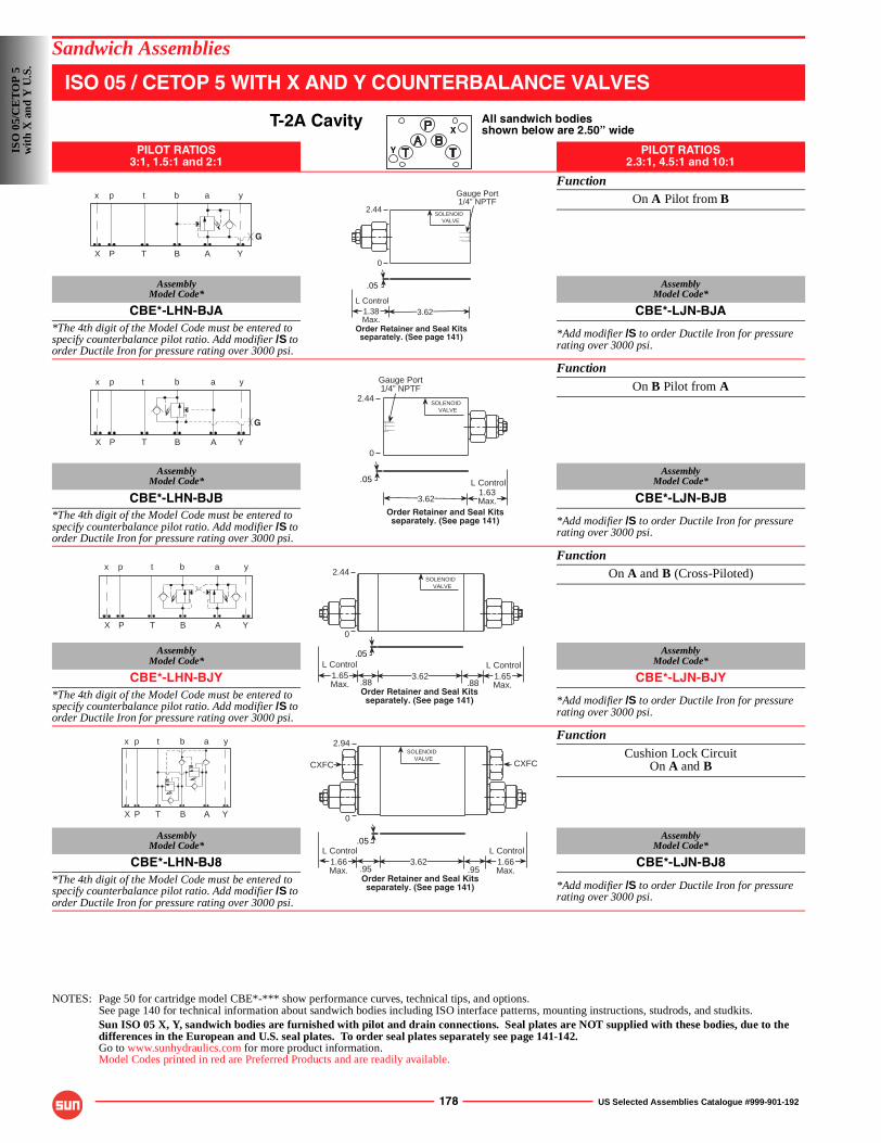
178 US Selected Assemblies Catalogue #999-901-192
Sandwich Assemblies
ISO 05 / CETOP 5 WITH X AND Y COUNTERBALANCE VALVES
T-2A Cavity All sandwich bodiesshown below are 2.50” wide
PILOT RATIOS3:1, 1.5:1 and 2:1
PILOT RATIOS2.3:1, 4.5:1 and 10:1
FunctionOn A Pilot from B
AssemblyModel Code*
AssemblyModel Code*
CBE*-LHN-BJA CBE*-LJN-BJA*The 4th digit of the Model Code must be entered to specify counterbalance pilot ratio. Add modifier /S to order Ductile Iron for pressure rating over 3000 psi.
*Add modifier /S to order Ductile Iron for pressure rating over 3000 psi.
Function
On B Pilot from A
AssemblyModel Code*
AssemblyModel Code*
CBE*-LHN-BJB CBE*-LJN-BJB*The 4th digit of the Model Code must be entered to specify counterbalance pilot ratio. Add modifier /S to order Ductile Iron for pressure rating over 3000 psi.
*Add modifier /S to order Ductile Iron for pressure rating over 3000 psi.
FunctionOn A and B (Cross-Piloted)
AssemblyModel Code*
AssemblyModel Code*
CBE*-LHN-BJY CBE*-LJN-BJY*The 4th digit of the Model Code must be entered to specify counterbalance pilot ratio. Add modifier /S to order Ductile Iron for pressure rating over 3000 psi.
*Add modifier /S to order Ductile Iron for pressure rating over 3000 psi.
Function
Cushion Lock CircuitOn A and B
AssemblyModel Code*
AssemblyModel Code*
CBE*-LHN-BJ8 CBE*-LJN-BJ8*The 4th digit of the Model Code must be entered to specify counterbalance pilot ratio. Add modifier /S to order Ductile Iron for pressure rating over 3000 psi.
*Add modifier /S to order Ductile Iron for pressure rating over 3000 psi.
NOTES: Page 50 for cartridge model CBE*-*** show performance curves, technical tips, and options.See page 140 for technical information about sandwich bodies including ISO interface patterns, mounting instructions, studrods, and studkits.Sun ISO 05 X, Y, sandwich bodies are furnished with pilot and drain connections. Seal plates are NOT supplied with these bodies, due to the differences in the European and U.S. seal plates. To order seal plates separately see page 141-142.Go to www.sunhydraulics.com for more product information.Model Codes printed in red are Preferred Products and are readily available.
X
Y
P T B A
p t b a
G
X
x
Y
y
2.44
Gauge Port1/4” NPTF
.05
SOLENOIDVALVE
3.621.38Max.
L Control
0
Order Retainer and Seal Kitsseparately. (See page 141)
G
P T B A
p t b a
X
x
Y
y
2.44
3.621.63Max.
L Control.05
Gauge Port1/4” NPTF
SOLENOIDVALVE
0
Order Retainer and Seal Kitsseparately. (See page 141)
P T B A
p t b a
X
x
Y
y
.05
2.44SOLENOID
VALVE
.88.883.62 1.65
Max.
L Control1.65Max.
L Control
0
Order Retainer and Seal Kitsseparately. (See page 141)
P T B A
p t b a
X
x
Y
y 2.94
.05
SOLENOIDVALVE
.95 .953.62 1.66
Max.
L Control1.66Max.
L Control
0
Order Retainer and Seal Kitsseparately. (See page 141)
CXFC CXFC
ISO
05/
CE
TO
P 5
wit
h X
and
Y U
.S.
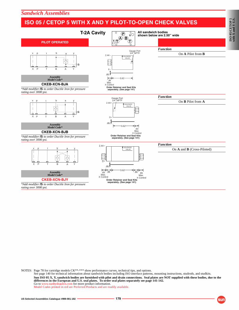
US Selected Assemblies Catalogue #999-901-192 179
Sandwich Assemblies
ISO 05 / CETOP 5 WITH X AND Y PILOT-TO-OPEN CHECK VALVES
T-2A Cavity All sandwich bodiesshown below are 2.50” wide
PILOT OPERATED
FunctionOn A Pilot from B
AssemblyModel Code*
CKEB-XCN-BJA*Add modifier /S to order Ductile Iron for pressure rating over 3000 psi.
FunctionOn B Pilot from A
AssemblyModel Code*
CKEB-XCN-BJB*Add modifier /S to order Ductile Iron for pressure rating over 3000 psi.
FunctionOn A and B (Cross-Piloted)
AssemblyModel Code*
CKEB-XCN-BJY*Add modifier /S to order Ductile Iron for pressure rating over 3000 psi.
NOTES: Page 78 for cartridge models CK**-*** show performance curves, technical tips, and options.See page 140 for technical information about sandwich bodies including ISO interface patterns, mounting instructions, studrods, and studkits.Sun ISO 05 X, Y, sandwich bodies are furnished with pilot and drain connections. Seal plates are NOT supplied with these bodies, due to the differences in the European and U.S. seal plates. To order seal plates separately see page 141-142.Go to www.sunhydraulics.com for more product information.Model Codes printed in red are Preferred Products and are readily available.
X
Y
P T B A
p t b a
G
X
x
Y
y2.44
Gauge Port1/4” NPTF
.05
SOLENOIDVALVE
3.62.38
Max.X Control
0
Order Retainer and Seal Kitsseparately. (See page 141)
G
P T B A
p t b a
X
x
Y
y
3.62
2.44
.63Max.
X Control
Gauge Port1/4” NPTF
.05
SOLENOIDVALVE
0
Order Retainer and Seal Kitsseparately. (See page 141)
P T B A
p t b a
X
x
Y
y
.05
.88.883.62
X Control
2.44
.65Max.
X Control
SOLENOIDVALVE
.65Max.
0
Order Retainer and Seal Kitsseparately. (See page 141)
ISO
05/
CE
TO
P 5
wit
h X
and
Y U
.S.
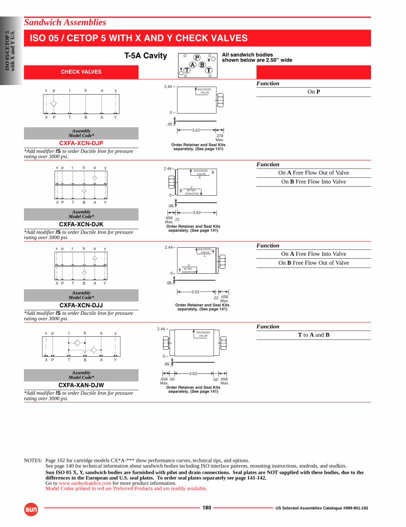
180 US Selected Assemblies Catalogue #999-901-192
Sandwich Assemblies
ISO 05 / CETOP 5 WITH X AND Y CHECK VALVES
T-5A Cavity All sandwich bodiesshown below are 2.50” wide
CHECK VALVES
FunctionOn P
AssemblyModel Code*
CXFA-XCN-DJP*Add modifier /S to order Ductile Iron for pressure rating over 3000 psi.
FunctionOn A Free Flow Out of Valve
On B Free Flow Into Valve
AssemblyModel Code*
CXFA-XCN-DJK*Add modifier /S to order Ductile Iron for pressure rating over 3000 psi.
FunctionOn A Free Flow Into Valve
On B Free Flow Out of Valve
AssemblyModel Code*
CXFA-XCN-DJJ*Add modifier /S to order Ductile Iron for pressure rating over 3000 psi.
FunctionT to A and B
AssemblyModel Code*
CXFA-XAN-DJW*Add modifier /S to order Ductile Iron for pressure rating over 3000 psi.
NOTES: Page 102 for cartridge models CX*A-*** show performance curves, technical tips, and options.See page 140 for technical information about sandwich bodies including ISO interface patterns, mounting instructions, studrods, and studkits.Sun ISO 05 X, Y, sandwich bodies are furnished with pilot and drain connections. Seal plates are NOT supplied with these bodies, due to the differences in the European and U.S. seal plates. To order seal plates separately see page 141-142.Go to www.sunhydraulics.com for more product information.Model Codes printed in red are Preferred Products and are readily available.
X
Y
P T B A
p t b a
X
x
Y
y2.44
.378 Max.
.05
3.62
SOLENOIDVALVE
0
Order Retainer and Seal Kitsseparately. (See page 141)
P T B A
p t b a
X
x
Y
y
.22
3.62.658 Max.
2.44
.05
B
A
SOLENOIDVALVE
SOLENOIDVALVE
0
Order Retainer and Seal Kitsseparately. (See page 141)
P T B A
p t b a
X
x
Y
y
.22 .658 Max.
2.44
.05
3.62
A
B
SOLENOIDVALVE
SOLENOIDVALVE
0
Order Retainer and Seal Kitsseparately. (See page 141)
P T B A
p t b a
X
x
Y
y
.50 .50
3.62
2.44
.658 Max.
.658 Max.
.05
SOLENOIDVALVE
0
Order Retainer and Seal Kitsseparately. (See page 141)
ISO
05/
CE
TO
P 5
wit
h X
and
Y U
.S.
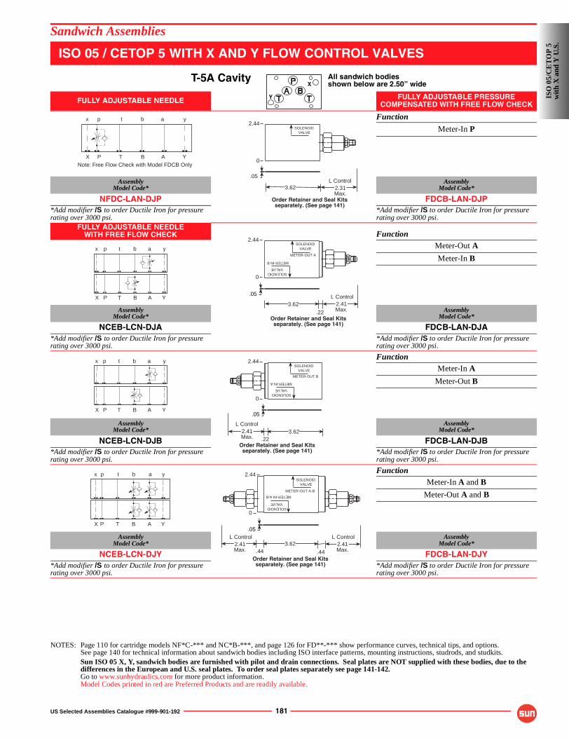
US Selected Assemblies Catalogue #999-901-192 181
Sandwich Assemblies
ISO 05 / CETOP 5 WITH X AND Y FLOW CONTROL VALVES
T-5A Cavity All sandwich bodiesshown below are 2.50” wide
FULLY ADJUSTABLE NEEDLE FULLY ADJUSTABLE PRESSURE COMPENSATED WITH FREE FLOW CHECK
Function
Meter-In P
AssemblyModel Code*
AssemblyModel Code*
NFDC-LAN-DJP FDCB-LAN-DJP*Add modifier /S to order Ductile Iron for pressure rating over 3000 psi.
*Add modifier /S to order Ductile Iron for pressure rating over 3000 psi.
FULLY ADJUSTABLE NEEDLEWITH FREE FLOW CHECK Function
Meter-Out A
Meter-In B
AssemblyModel Code*
AssemblyModel Code*
NCEB-LCN-DJA FDCB-LAN-DJA*Add modifier /S to order Ductile Iron for pressure rating over 3000 psi.
*Add modifier /S to order Ductile Iron for pressure rating over 3000 psi.
FunctionMeter-In A
Meter-Out B
AssemblyModel Code*
AssemblyModel Code*
NCEB-LCN-DJB FDCB-LAN-DJB*Add modifier /S to order Ductile Iron for pressure rating over 3000 psi.
*Add modifier /S to order Ductile Iron for pressure rating over 3000 psi.
FunctionMeter-In A and B
Meter-Out A and B
AssemblyModel Code*
AssemblyModel Code*
NCEB-LCN-DJY FDCB-LAN-DJY*Add modifier /S to order Ductile Iron for pressure rating over 3000 psi.
*Add modifier /S to order Ductile Iron for pressure rating over 3000 psi.
NOTES: Page 110 for cartridge models NF*C-*** and NC*B-***, and page 126 for FD**-*** show performance curves, technical tips, and options.See page 140 for technical information about sandwich bodies including ISO interface patterns, mounting instructions, studrods, and studkits.Sun ISO 05 X, Y, sandwich bodies are furnished with pilot and drain connections. Seal plates are NOT supplied with these bodies, due to the differences in the European and U.S. seal plates. To order seal plates separately see page 141-142.Go to www.sunhydraulics.com for more product information.Model Codes printed in red are Preferred Products and are readily available.
X
Y
Note: Free Flow Check with Model FDCB OnlyP T B A
p t b a
X
x
Y
y
3.62 2.31Max.
L Control
2.44
.05
SOLENOIDVALVE
0
Order Retainer and Seal Kitsseparately. (See page 141)
.22
3.62 2.41Max.
L Control
2.44
.05
METER-OUT A
METER-IN B
SOLENOIDVALVE
SOLENOIDVALVE
0
Order Retainer and Seal Kitsseparately. (See page 141)
P T B A
p t b a
X
x
Y
y
P T B A
p t b a
X
x
Y
y
.22
2.44
.05
METER-OUT B
METER-IN A
SOLENOIDVALVE
SOLENOIDVALVE
3.622.41Max.
L Control
0
Order Retainer and Seal Kitsseparately. (See page 141)
P T B A
p t b a
X
x
Y
y
.44 .44
3.62
2.44
2.41Max.
L Control2.41Max.
L Control.05
METER-OUT A-B
METER-IN A-B
SOLENOIDVALVE
SOLENOIDVALVE
0
Order Retainer and Seal Kitsseparately. (See page 141)
ISO
05/
CE
TO
P 5
wit
h X
and
Y U
.S.
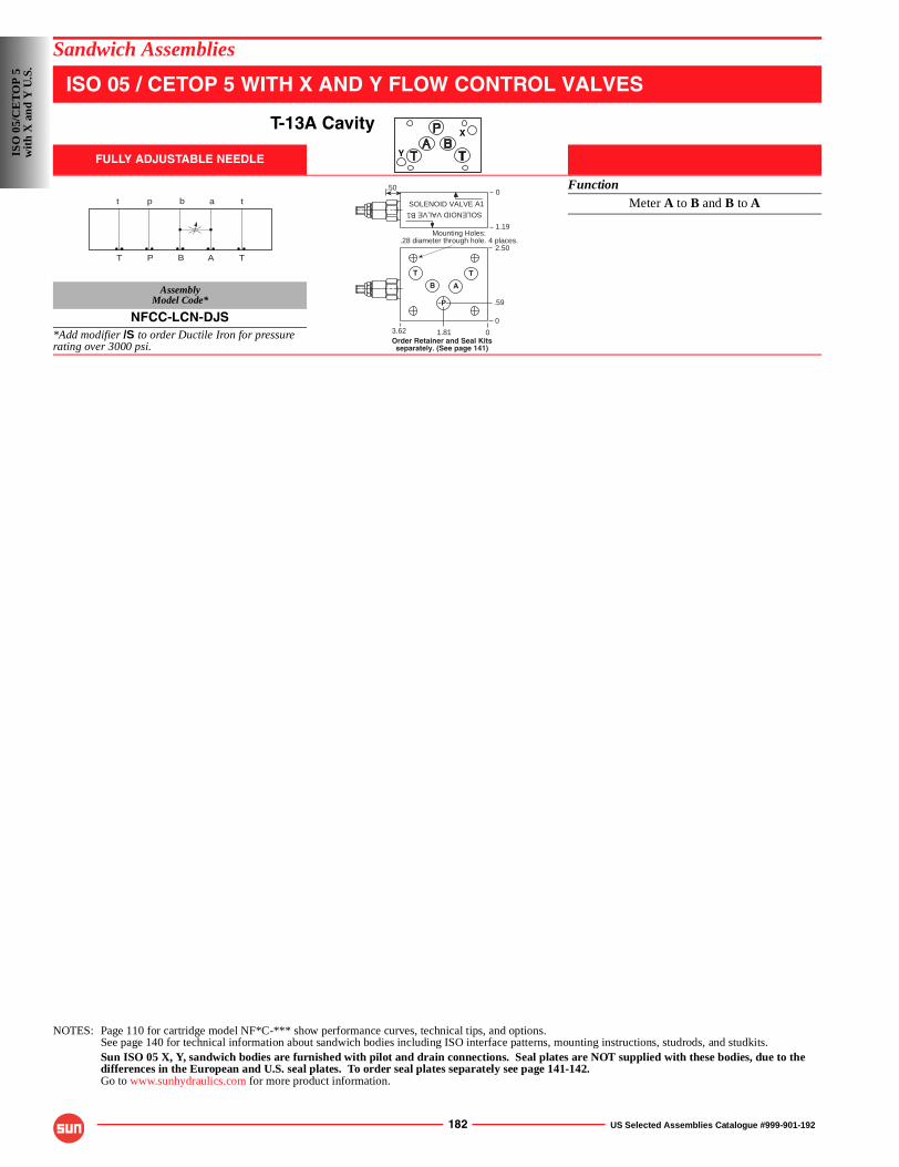
182 US Selected Assemblies Catalogue #999-901-192
Sandwich Assemblies
ISO 05 / CETOP 5 WITH X AND Y FLOW CONTROL VALVES
T-13A Cavity
FULLY ADJUSTABLE NEEDLE
FunctionMeter A to B and B to A
AssemblyModel Code*
NFCC-LCN-DJS*Add modifier /S to order Ductile Iron for pressure rating over 3000 psi.
NOTES: Page 110 for cartridge model NF*C-*** show performance curves, technical tips, and options.See page 140 for technical information about sandwich bodies including ISO interface patterns, mounting instructions, studrods, and studkits.Sun ISO 05 X, Y, sandwich bodies are furnished with pilot and drain connections. Seal plates are NOT supplied with these bodies, due to the differences in the European and U.S. seal plates. To order seal plates separately see page 141-142.Go to www.sunhydraulics.com for more product information.
X
Y
A
a
T
t
P
p
T
t
B
b
Order Retainer and Seal Kitsseparately. (See page 141)
SOLENOID VALVEB1
SOLENOID VALVE A1
1.19
.500
Mounting Holes:.28 diameter through hole. 4 places.
0
0
2.50
.59
1.813.62
T T
P
AB
ISO
05/
CE
TO
P 5
wit
h X
and
Y U
.S.
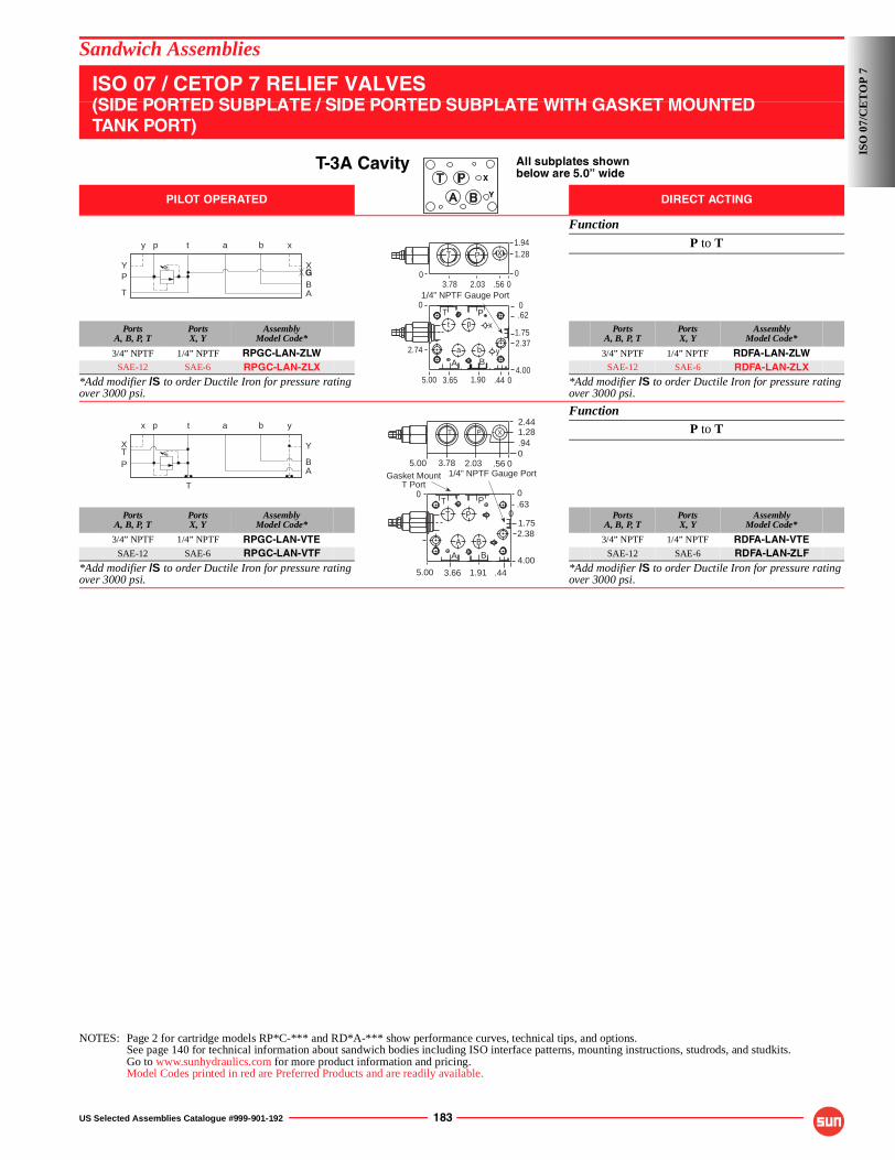
US Selected Assemblies Catalogue #999-901-192 183
Sandwich Assemblies
ISO 07 / CETOP 7 RELIEF VALVES(SIDE PORTED SUBPLATE / SIDE PORTED SUBPLATE WITH GASKET MOUNTEDTANK PORT)
T-3A Cavity All subplates shownbelow are 5.0” wide
PILOT OPERATED DIRECT ACTING
Function
P to T
PortsA, B, P, T
PortsX, Y
AssemblyModel Code*
PortsA, B, P, T
PortsX, Y
AssemblyModel Code*
3/4” NPTF 1/4” NPTF RPGC-LAN-ZLW 3/4” NPTF 1/4” NPTF RDFA-LAN-ZLWSAE-12 SAE-6 RPGC-LAN-ZLX SAE-12 SAE-6 RDFA-LAN-ZLX
*Add modifier /S to order Ductile Iron for pressure rating over 3000 psi.
*Add modifier /S to order Ductile Iron for pressure rating over 3000 psi.
FunctionP to T
PortsA, B, P, T
PortsX, Y
AssemblyModel Code*
PortsA, B, P, T
PortsX, Y
AssemblyModel Code*
3/4” NPTF 1/4” NPTF RPGC-LAN-VTE 3/4” NPTF 1/4” NPTF RDFA-LAN-VTESAE-12 SAE-6 RPGC-LAN-VTF SAE-12 SAE-6 RDFA-LAN-ZLF
*Add modifier /S to order Ductile Iron for pressure rating over 3000 psi.
*Add modifier /S to order Ductile Iron for pressure rating over 3000 psi.
NOTES: Page 2 for cartridge models RP*C-*** and RD*A-*** show performance curves, technical tips, and options.See page 140 for technical information about sandwich bodies including ISO interface patterns, mounting instructions, studrods, and studkits.Go to www.sunhydraulics.com for more product information and pricing.Model Codes printed in red are Preferred Products and are readily available.
X
Y
P
T AB
tp a b
Y
y
X
x
G
2.74
1/4” NPTF Gauge Port
P
A B
00
y
x
a b
pt
5.00 3.65 1.90 0.444.00
.62
1.752.37
0
X
0
1.94T P 1.28
0.562.033.78
T
P
T
AB
p t a b
X
x
Y
y
T
0
1/4” NPTF Gauge Port
T P
A B
5.00 3.66 1.91 .44
0.63
1.752.38
4.00
5.00 3.78 2.03 .560
0
.94
2.441.28XPT
P
A B
Gasket MountT Port
yx
0T
ISO
07/
CE
TO
P 7
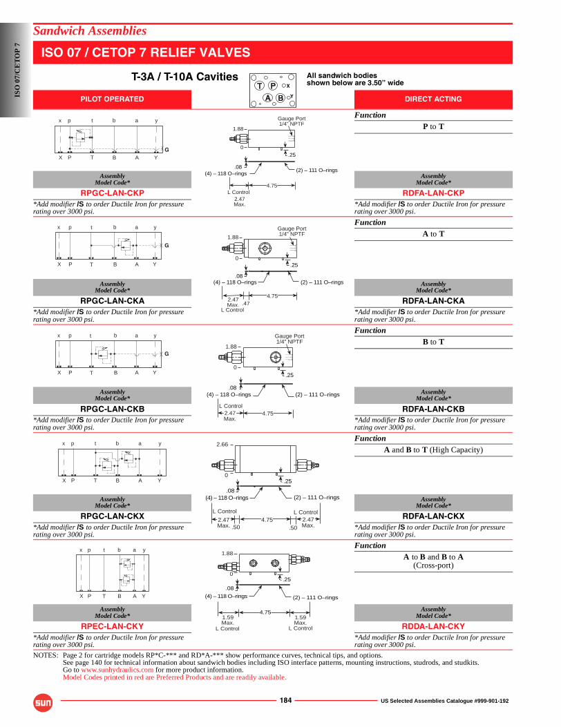
184 US Selected Assemblies Catalogue #999-901-192
Sandwich Assemblies
ISO 07 / CETOP 7 RELIEF VALVES
T-3A / T-10A Cavities All sandwich bodiesshown below are 3.50” wide
PILOT OPERATED DIRECT ACTING
FunctionP to T
AssemblyModel Code*
AssemblyModel Code*
RPGC-LAN-CKP RDFA-LAN-CKP*Add modifier /S to order Ductile Iron for pressure rating over 3000 psi.
*Add modifier /S to order Ductile Iron for pressure rating over 3000 psi.
FunctionA to T
AssemblyModel Code*
AssemblyModel Code*
RPGC-LAN-CKA RDFA-LAN-CKA*Add modifier /S to order Ductile Iron for pressure rating over 3000 psi.
*Add modifier /S to order Ductile Iron for pressure rating over 3000 psi.
FunctionB to T
AssemblyModel Code*
AssemblyModel Code*
RPGC-LAN-CKB RDFA-LAN-CKB*Add modifier /S to order Ductile Iron for pressure rating over 3000 psi.
*Add modifier /S to order Ductile Iron for pressure rating over 3000 psi.
FunctionA and B to T (High Capacity)
AssemblyModel Code*
AssemblyModel Code*
RPGC-LAN-CKX RDFA-LAN-CKX*Add modifier /S to order Ductile Iron for pressure rating over 3000 psi.
*Add modifier /S to order Ductile Iron for pressure rating over 3000 psi.
FunctionA to B and B to A
(Cross-port)
AssemblyModel Code*
AssemblyModel Code*
RPEC-LAN-CKY RDDA-LAN-CKY*Add modifier /S to order Ductile Iron for pressure rating over 3000 psi.
*Add modifier /S to order Ductile Iron for pressure rating over 3000 psi.
NOTES: Page 2 for cartridge models RP*C-*** and RD*A-*** show performance curves, technical tips, and options.See page 140 for technical information about sandwich bodies including ISO interface patterns, mounting instructions, studrods, and studkits.Go to www.sunhydraulics.com for more product information.Model Codes printed in red are Preferred Products and are readily available.
X
Y
GP T B A
p t b a
X
x
Y
y
(4) – 118 O–rings(2) – 111 O–rings
.08
Gauge Port1/4” NPTF
2.47Max.
L Control
.25
1.88
4.75
0
P T B A
G
p t b a
X
x
Y
y
(4) – 118 O–rings (2) – 111 O–rings.08
.25
Gauge Port1/4” NPTF
.47
1.88
2.47Max.
L Control
4.75
0
G
P T B A
p t b a
X
x
Y
y
(4) – 118 O–rings.08
(2) – 111 O–rings
2.47Max.
L Control
Gauge Port1/4” NPTF
1.88
.25
4.75
0
P T B A
p t b a
X
x
Y
y
.25
2.66
.502.47Max.
L Control4.75
.502.47Max.
L Control
.08(4) – 118 O–rings (2) – 111 O–rings
0
P T B A
p t b a
X
x
Y
y
.08
(4) – 118 O–rings (2) – 111 O–rings
.25
1.59Max.
L Control
1.59Max.
L Control
4.75
1.88
0
ISO
07/
CE
TO
P 7
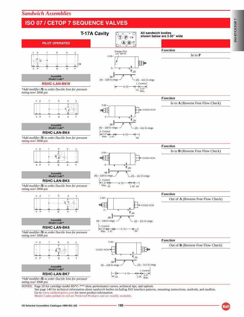
US Selected Assemblies Catalogue #999-901-192 185
Sandwich Assemblies
ISO 07 / CETOP 7 SEQUENCE VALVES
T-17A Cavity All sandwich bodiesshown below are 3.50” wide
PILOT OPERATED
FunctionIn to P
AssemblyModel Code*
RSHC-LAN-BKW
*Add modifier /S to order Ductile Iron for pressure rating over 3000 psi.
FunctionIn to A (Reverse Free Flow Check)
AssemblyModel Code*
RSHC-LAN-BK4*Add modifier /S to order Ductile Iron for pressure rating over 3000 psi.
FunctionIn to B (Reverse Free Flow Check)
AssemblyModel Code*
RSHC-LAN-BK5*Add modifier /S to order Ductile Iron for pressure rating over 3000 psi.
FunctionOut of A (Reverse Free Flow Check)
AssemblyModel Code*
RSHC-LAN-BK6*Add modifier /S to order Ductile Iron for pressure rating over 3000 psi.
FunctionOut of B (Reverse Free Flow Check)
AssemblyModel Code*
RSHC-LAN-BK7*Add modifier /S to order Ductile Iron for pressure rating over 3000 psi.NOTES: Page 20 for cartridge model RS*C-*** show performance curves, technical tips, and options.
See page 140 for technical information about sandwich bodies including ISO interface patterns, mounting instructions, studrods, and studkits.Go to www.sunhydraulics.com for more product information.Model Codes printed in red are Preferred Products and are readily available.
X
Y
G
P T B A
p t b a
X
x
Y
y
.08(2) – 111 O–rings(4) – 118 O–rings
.25
2.66
.754.75
2.37Max.
L Control
Gauge Port1/4” NPTF
0
P T B A
p t b a
X
x
Y
y
.08
1.41
2.66
(4) – 118 O–rings
.25
(2) – 111 O–rings
2.37Max.
L Control4.75
.94
CXGD-XCN
0
P T B A
p t b a
X
x
Y
y
.08
4.75
2.66
(2) – 111 O–rings
.25
CXGD-XCN
(4) – 118 O–rings
.941.09.162.37Max.
L Control
0
P T B A
p t b a
X
x
Y
y
.08
4.75
2.66
(2) – 111 O–rings
.25
CXGD-XCN
(4) – 118 O–rings
.941.412.37Max.
L Control
0
P T B A
p t b a
X
x
Y
y
.08(2) – 111 O–rings
.25
.164.75
(4) – 118 O–rings
CXGD-XCN
2.37Max.
L Control
1.09.94
2.66
0
ISO
07/
CE
TO
P 7

186 US Selected Assemblies Catalogue #999-901-192
Sandwich Assemblies
ISO 07 / CETOP 7 REDUCING VALVES
T-17A Cavity All sandwich bodiesshown below are 3.50” wide
PILOT OPERATED
FunctionOn P Drained to T
AssemblyModel Code*
PBHB-LAN-BKP*Add modifier /S to order Ductile Iron for pressure rating over 3000 psi.
FunctionOn A Drained to B
AssemblyModel Code*
PBHB-LAN-BKA*Add modifier /S to order Ductile Iron for pressure rating over 3000 psi.
FunctionOn B Drained to A
AssemblyModel Code*
PBHB-LAN-BKB*Add modifier /S to order Ductile Iron for pressure rating over 3000 psi.
FunctionOn A Drain to T
(Reverse Free Flow Check)
AssemblyModel Code*
PBHB-LAN-BK2*Add modifier /S to order Ductile Iron for pressure rating over 3000 psi.
FunctionOn B Drain to T
(Reverse Free Flow Check)
AssemblyModel Code*
PBHB-LAN-BKJ*Add modifier /S to order Ductile Iron for pressure rating over 3000 psi.NOTES: Page 34 for cartridge model PB*B-*** and page 102 for CX*A-*** shows performance curves, technical tips, and options.
See page 140 for technical information about sandwich bodies including ISO interface patterns, mounting instructions, studrods, and studkits.Go to www.sunhydraulics.com for more product information.Model Codes printed in red are Preferred Products and are readily available.
X
Y
G
P T B A
p t b a
X
x
Y
y
2.66
(4) – 118 O–rings
.25.08
(2) – 111 O–rings
4.75
Gauge Port1/4” NPTF
2.37Max.
L Control
.75
0
P T B A
p t b a
X
x
Y
y
.08
2.66
(2) – 111 O–rings
.25
(4) – 118 O–rings
.974.75
2.37Max.
L Control
0
P T B A
p t b a
X
x
Y
y
.08
2.66
(2) – 111 O–rings
.25
(4) – 118 O–rings
4.75 2.37Max.
L Control
.91
0
p t b a
P T B AX
x
Y
y
.08
2.66
(4) – 118 O–rings
.25
4.751.41
(2) – 111 O–rings
CXHA-XCN
2.37Max.
L Control
.78
0
P T B A
p t b a
X
x
Y
y
.08
2.66
(2) – 111 O–rings
.25
CXHA-XCN
.16
4.75
(4) – 118 O–rings
2.37Max.
L Control
1.09 .94
0
ISO
07/
CE
TO
P 7
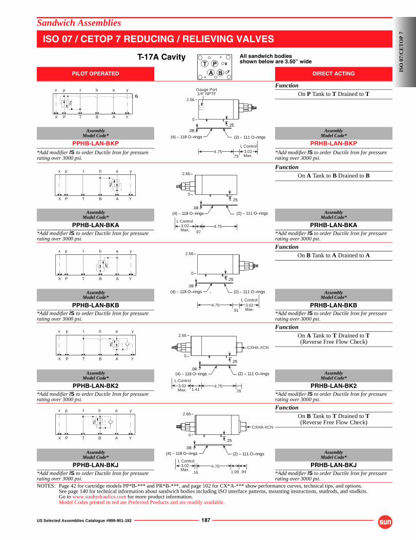
US Selected Assemblies Catalogue #999-901-192 187
Sandwich Assemblies
ISO 07 / CETOP 7 REDUCING / RELIEVING VALVES
T-17A Cavity All sandwich bodiesshown below are 3.50” wide
PILOT OPERATED DIRECT ACTING
FunctionOn P Tank to T Drained to T
AssemblyModel Code*
AssemblyModel Code*
PPHB-LAN-BKP PRHB-LAN-BKP*Add modifier /S to order Ductile Iron for pressure rating over 3000 psi.
*Add modifier /S to order Ductile Iron for pressure rating over 3000 psi.
FunctionOn A Tank to B Drained to B
AssemblyModel Code*
AssemblyModel Code*
PPHB-LAN-BKA PRHB-LAN-BKA*Add modifier /S to order Ductile Iron for pressure rating over 3000 psi.
*Add modifier /S to order Ductile Iron for pressure rating over 3000 psi.
FunctionOn B Tank to A Drained to A
AssemblyModel Code*
AssemblyModel Code*
PPHB-LAN-BKB PRHB-LAN-BKB*Add modifier /S to order Ductile Iron for pressure rating over 3000 psi.
*Add modifier /S to order Ductile Iron for pressure rating over 3000 psi.
FunctionOn A Tank to T Drained to T(Reverse Free Flow Check)
AssemblyModel Code*
AssemblyModel Code*
PPHB-LAN-BK2 PRHB-LAN-BK2*Add modifier /S to order Ductile Iron for pressure rating over 3000 psi.
*Add modifier /S to order Ductile Iron for pressure rating over 3000 psi.
FunctionOn B Tank to T Drained to T(Reverse Free Flow Check)
AssemblyModel Code*
AssemblyModel Code*
PPHB-LAN-BKJ PRHB-LAN-BKJ*Add modifier /S to order Ductile Iron for pressure rating over 3000 psi.
*Add modifier /S to order Ductile Iron for pressure rating over 3000 psi.
NOTES: Page 42 for cartridge models PP*B-*** and PR*B-***, and page 102 for CX*A-*** show performance curves, technical tips, and options.See page 140 for technical information about sandwich bodies including ISO interface patterns, mounting instructions, studrods, and studkits.Go to www.sunhydraulics.com for more product information.Model Codes printed in red are Preferred Products and are readily available.
X
Y
G
P T B A
p t b a
X
x
Y
y
2.66
(4) – 118 O–rings
.25.08
(2) – 111 O–rings
4.75
Gauge Port1/4” NPTF
3.02Max.
L Control
.75
0
P T B A
p t b a
X
x
Y
y
.08
2.66
(2) – 111 O–rings
.25
(4) – 118 O–rings
.974.753.02
Max.
L Control
0
P T B A
p t b a
X
x
Y
y
.08
2.66
(2) – 111 O–rings
.25
(4) – 118 O–rings
4.75 3.02Max.
L Control
.91
0
P T B A
p t b a
X
x
Y
y
.08
2.66
(4) – 118 O–rings
.25
4.751.41
(2) – 111 O–rings
CXHA-XCN
3.02Max.
L Control
.78
0
P T B A
p t b a
X
x
Y
y
.08
2.66
(2) – 111 O–rings
.25
CXHA-XCN
.16
4.75
(4) – 118 O–rings
3.02Max.
L Control
1.09 .94
0
ISO
07/
CE
TO
P 7

188 US Selected Assemblies Catalogue #999-901-192
Sandwich Assemblies
ISO 07 / CETOP 7 COUNTERBALANCE VALVES
T-17A Cavity All sandwich bodiesshown below are 3.50” wide
PILOT RATIOS3:1, 2:1 and 1.5:1
PILOT RATIOS2.3:1, 4.5:1 and 10:1
FunctionOn A Pilot from B
AssemblyModel Code*
AssemblyModel Code*
CBG*-LHN-BKA CBG*-LJN-BKA*Add modifier /S to order Ductile Iron for pressure rating over 3000 psi.
*Add modifier /S to order Ductile Iron for pressure rating over 3000 psi.
FunctionOn B Pilot from A
AssemblyModel Code*
AssemblyModel Code*
CBG*-LHN-BKB CBG*-LJN-BKB*Add modifier /S to order Ductile Iron for pressure rating over 3000 psi.
*Add modifier /S to order Ductile Iron for pressure rating over 3000 psi.
FunctionOn A and B (Cross-piloted)
AssemblyModel Code*
AssemblyModel Code*
CBG*-LHN-BKY CBG*-LJN-BKY*Add modifier /S to order Ductile Iron for pressure rating over 3000 psi.
*Add modifier /S to order Ductile Iron for pressure rating over 3000 psi.
NOTES: Page 50 for cartridge model CB**-*** show performance curves, technical tips, and options.See page 140 for technical information about sandwich bodies including ISO interface patterns, mounting instructions, studrods, and studkits.Go to www.sunhydraulics.com for more product information.Model Codes printed in red are Preferred Products and are readily available.
X
Y
P T B A
p t b a
X
x
Y
y
.08
.974.75
1.84Max.
L Control
(2) – 111 O–rings
.25
(4) – 118 O–rings
2.66
0
P T B A
p t b a
X
x
Y
y
.08(2) – 111 O–rings
.25
(4) – 118 O–rings
2.66
.914.75
1.84Max.
L Control
0
P T B A
p t b a
X
x
Y
y2.66
.08
(2) – 111 O–rings
1.444.75
(4) – 118 O–rings
1.84Max.
L Control
1.84Max.
L Control
1.37
.250
ISO
07/
CE
TO
P 7
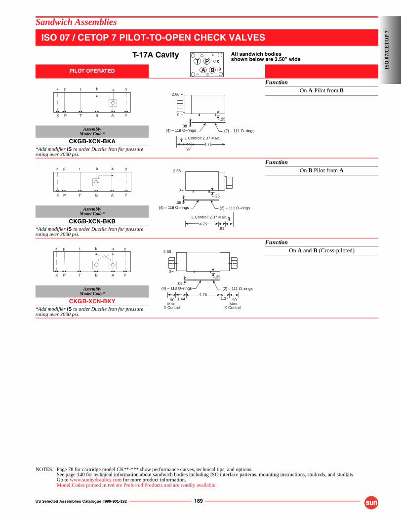
US Selected Assemblies Catalogue #999-901-192 189
Sandwich Assemblies
ISO 07 / CETOP 7 PILOT-TO-OPEN CHECK VALVES
T-17A Cavity All sandwich bodiesshown below are 3.50” wide
PILOT OPERATED
FunctionOn A Pilot from B
AssemblyModel Code*
CKGB-XCN-BKA*Add modifier /S to order Ductile Iron for pressure rating over 3000 psi.
FunctionOn B Pilot from A
AssemblyModel Code*
CKGB-XCN-BKB*Add modifier /S to order Ductile Iron for pressure rating over 3000 psi.
FunctionOn A and B (Cross-piloted)
AssemblyModel Code*
CKGB-XCN-BKY*Add modifier /S to order Ductile Iron for pressure rating over 3000 psi.
NOTES: Page 78 for cartridge model CK**-*** show performance curves, technical tips, and options.See page 140 for technical information about sandwich bodies including ISO interface patterns, mounting instructions, studrods, and studkits.Go to www.sunhydraulics.com for more product information.Model Codes printed in red are Preferred Products and are readily available.
X
Y
P T B A
p t b a
X
x
Y
y
.08
.974.75
L Control: 2.37 Max.
2.66
(2) – 111 O–rings
.25
(4) – 118 O–rings
0
P T B A
p t b a
X
x
Y
y
.08
.914.75
2.66
(2) – 111 O–rings
.25
(4) – 118 O–rings
0
L Control: 2.37 Max.
P T B A
p t b a
X
x
Y
y
.08
2.66
(2) – 111 O–rings
.25
1.444.75
(4) – 118 O–rings
.90Max.
X Control
.90Max.
X Control
1.37
0
ISO
07/
CE
TO
P 7
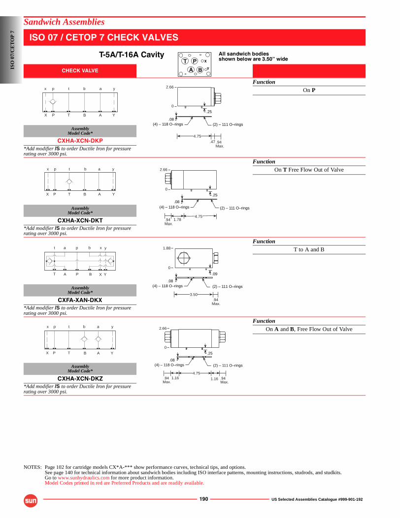
190 US Selected Assemblies Catalogue #999-901-192
Sandwich Assemblies
ISO 07 / CETOP 7 CHECK VALVES
T-5A/T-16A Cavity All sandwich bodiesshown below are 3.50” wide
CHECK VALVE
FunctionOn P
AssemblyModel Code*
CXHA-XCN-DKP*Add modifier /S to order Ductile Iron for pressure rating over 3000 psi.
FunctionOn T Free Flow Out of Valve
AssemblyModel Code*
CXHA-XCN-DKT*Add modifier /S to order Ductile Iron for pressure rating over 3000 psi.
FunctionT to A and B
AssemblyModel Code*
CXFA-XAN-DKX*Add modifier /S to order Ductile Iron for pressure rating over 3000 psi.
FunctionOn A and B, Free Flow Out of Valve
AssemblyModel Code*
CXHA-XCN-DKZ*Add modifier /S to order Ductile Iron for pressure rating over 3000 psi.
NOTES: Page 102 for cartridge models CX*A-*** show performance curves, technical tips, and options.See page 140 for technical information about sandwich bodies including ISO interface patterns, mounting instructions, studrods, and studkits.Go to www.sunhydraulics.com for more product information.Model Codes printed in red are Preferred Products and are readily available.
X
Y
P T B A
p t b a
X
x
Y
y
.08(4) – 118 O–rings
2.66
.25
.94 Max.
.474.75
(2) – 111 O–rings
0
P T B A
p t b a
X
x
Y
y
.08(4) – 118 O–rings (2) – 111 O–rings
2.66
.25
.94 Max.
1.784.75
0
A
a
B
b
X
x
Y
y
T
t
P
p
.94 Max.
1.88
.09
3.50
0
.08(2) – 111 O–rings(4) – 118 O–rings
P T B A
p t b a
X
x
Y
y
.08
2.66
(2) – 111 O–rings
.25
(4) – 118 O–rings
.94 Max.
1.164.75
.94 Max.
1.16
0
ISO
07/
CE
TO
P 7
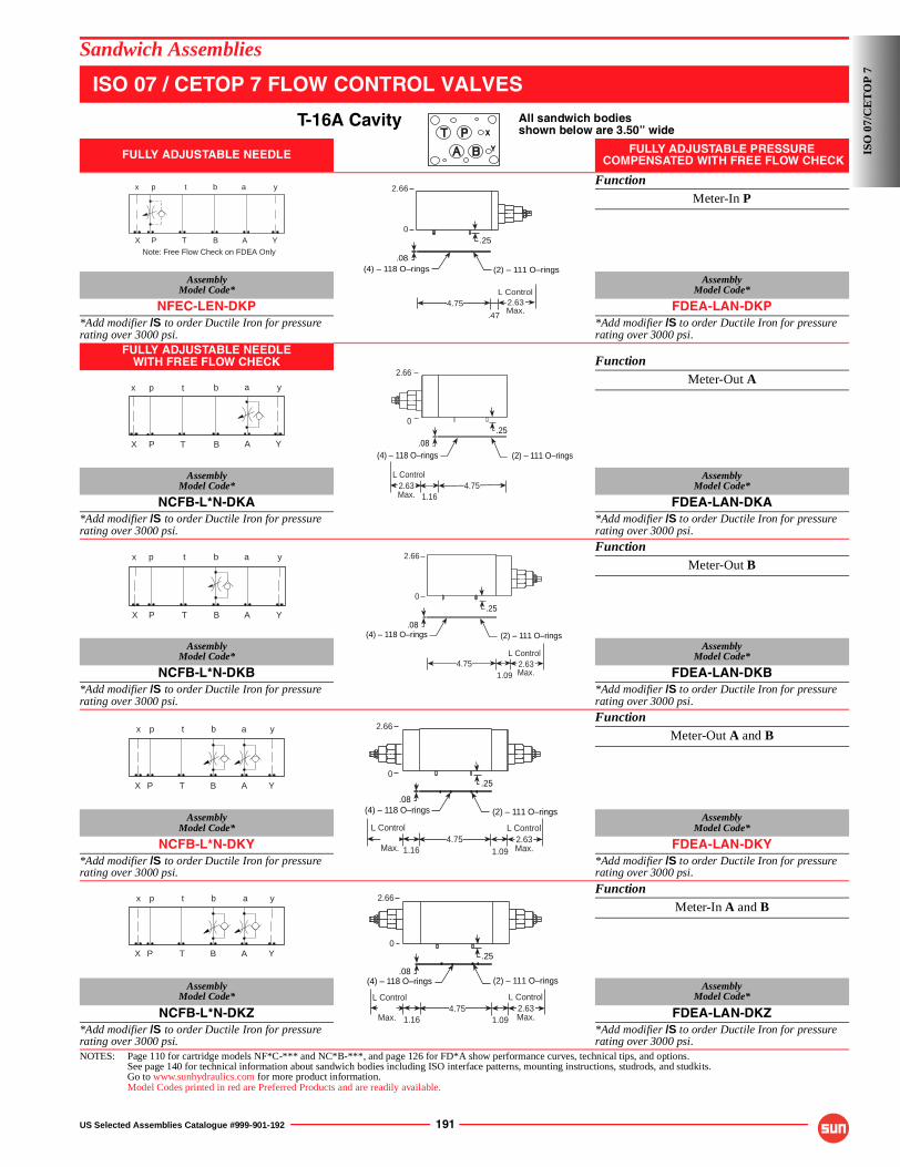
US Selected Assemblies Catalogue #999-901-192 191
Sandwich Assemblies
ISO 07 / CETOP 7 FLOW CONTROL VALVES
T-16A Cavity All sandwich bodiesshown below are 3.50” wide
FULLY ADJUSTABLE NEEDLE FULLY ADJUSTABLE PRESSURE COMPENSATED WITH FREE FLOW CHECK
FunctionMeter-In P
AssemblyModel Code*
AssemblyModel Code*
NFEC-LEN-DKP FDEA-LAN-DKP*Add modifier /S to order Ductile Iron for pressure rating over 3000 psi.
*Add modifier /S to order Ductile Iron for pressure rating over 3000 psi.
FULLY ADJUSTABLE NEEDLEWITH FREE FLOW CHECK Function
Meter-Out A
AssemblyModel Code*
AssemblyModel Code*
NCFB-L*N-DKA FDEA-LAN-DKA*Add modifier /S to order Ductile Iron for pressure rating over 3000 psi.
*Add modifier /S to order Ductile Iron for pressure rating over 3000 psi.
FunctionMeter-Out B
AssemblyModel Code*
AssemblyModel Code*
NCFB-L*N-DKB FDEA-LAN-DKB*Add modifier /S to order Ductile Iron for pressure rating over 3000 psi.
*Add modifier /S to order Ductile Iron for pressure rating over 3000 psi.
FunctionMeter-Out A and B
AssemblyModel Code*
AssemblyModel Code*
NCFB-L*N-DKY FDEA-LAN-DKY*Add modifier /S to order Ductile Iron for pressure rating over 3000 psi.
*Add modifier /S to order Ductile Iron for pressure rating over 3000 psi.
FunctionMeter-In A and B
AssemblyModel Code*
AssemblyModel Code*
NCFB-L*N-DKZ FDEA-LAN-DKZ*Add modifier /S to order Ductile Iron for pressure rating over 3000 psi.
*Add modifier /S to order Ductile Iron for pressure rating over 3000 psi.
NOTES: Page 110 for cartridge models NF*C-*** and NC*B-***, and page 126 for FD*A show performance curves, technical tips, and options.See page 140 for technical information about sandwich bodies including ISO interface patterns, mounting instructions, studrods, and studkits.Go to www.sunhydraulics.com for more product information.Model Codes printed in red are Preferred Products and are readily available.
X
Y
P T B A
p t b a
X
x
Y
y
Note: Free Flow Check on FDEA Only.08
2.66
(2) – 111 O–rings
.25
.47
4.75
(4) – 118 O–rings
2.63Max.
L Control
0
.08
2.66
(2) – 111 O–rings
.25
1.164.75
(4) – 118 O–rings
2.63Max.
L Control
0
P T B A
p t b a
X
x
Y
y
P T B A
p t b a
X
x
Y
y
.08
2.66
(2) – 111 O–rings
.25
1.094.75
(4) – 118 O–rings
2.63Max.
L Control
0
P T B A
p t b a
X
x
Y
y
.08
2.66
(2) – 111 O–rings
.25
1.094.75
(4) – 118 O–rings
Max.
L Control2.63Max.
L Control
1.16
0
P T B A
p t b a
X
x
Y
y
.08
2.66
(2) – 111 O–rings
.25
(4) – 118 O–rings
1.094.75 2.63
Max.
L Control
Max.
L Control
1.16
0
ISO
07/
CE
TO
P 7
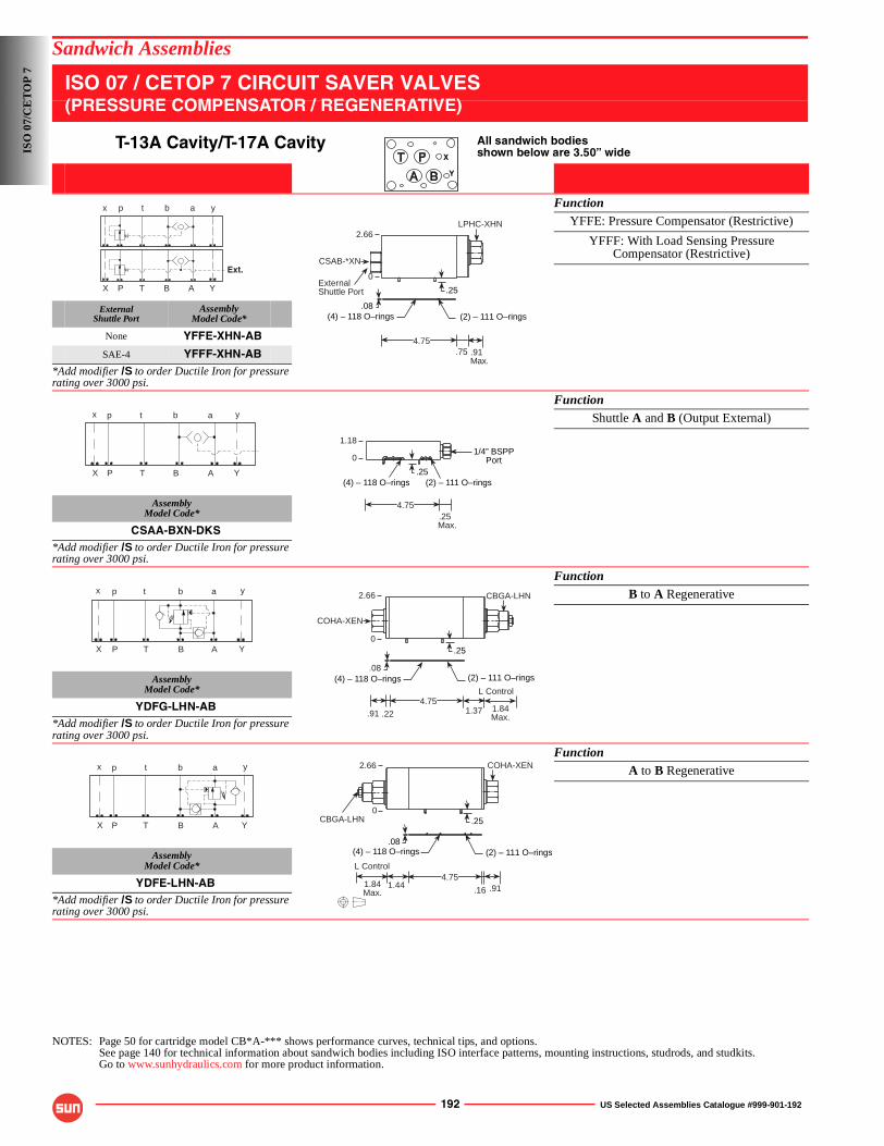
192 US Selected Assemblies Catalogue #999-901-192
Sandwich Assemblies
ISO 07 / CETOP 7 CIRCUIT SAVER VALVES(PRESSURE COMPENSATOR / REGENERATIVE)
T-13A Cavity/T-17A Cavity All sandwich bodiesshown below are 3.50” wide
FunctionYFFE: Pressure Compensator (Restrictive)
YFFF: With Load Sensing PressureCompensator (Restrictive)
ExternalShuttle Port
AssemblyModel Code*
None YFFE-XHN-AB
SAE-4 YFFF-XHN-AB*Add modifier /S to order Ductile Iron for pressure rating over 3000 psi.
FunctionShuttle A and B (Output External)
AssemblyModel Code*
CSAA-BXN-DKS*Add modifier /S to order Ductile Iron for pressure rating over 3000 psi.
FunctionB to A Regenerative
AssemblyModel Code*
YDFG-LHN-AB*Add modifier /S to order Ductile Iron for pressure rating over 3000 psi.
FunctionA to B Regenerative
AssemblyModel Code*
YDFE-LHN-AB*Add modifier /S to order Ductile Iron for pressure rating over 3000 psi.
NOTES: Page 50 for cartridge model CB*A-*** shows performance curves, technical tips, and options.See page 140 for technical information about sandwich bodies including ISO interface patterns, mounting instructions, studrods, and studkits.Go to www.sunhydraulics.com for more product information.
X
Y
P T B A
p t b a
X
x
Y
y
Ext.
(2) – 111 O–rings
.25
.08
.91 Max.
.754.75
LPHC-XHN
CSAB-*XN
2.66
0ExternalShuttle Port
(4) – 118 O–rings
P T B A
p t b a
X
x
Y
y
(4) – 118 O–rings
.25 Max.
4.75
1/4” BSPPPort
.25
1.18
0
(2) – 111 O–rings
P T B A
p t b a
X
x
Y
y
(2) – 111 O–rings
.25
COHA-XEN
1.374.75
1.84Max.
(4) – 118 O–rings.08
.22.91
CBGA-LHN
L Control
2.66
0
P T B A
p t b a
X
x
Y
y
.08(2) – 111 O–rings
.25
COHA-XEN
4.751.44
(4) – 118 O–rings
1.84Max. .16 .91
CBGA-LHN
L Control
2.66
0
ISO
07/
CE
TO
P 7
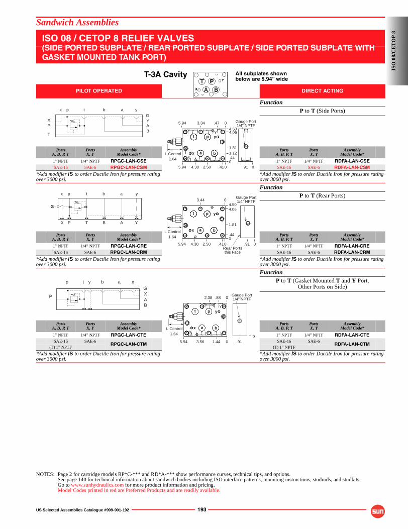
US Selected Assemblies Catalogue #999-901-192 193
Sandwich Assemblies
ISO 08 / CETOP 8 RELIEF VALVES(SIDE PORTED SUBPLATE / REAR PORTED SUBPLATE / SIDE PORTED SUBPLATE WITH GASKET MOUNTED TANK PORT)
T-3A Cavity All subplates shownbelow are 5.94” wide
PILOT OPERATED DIRECT ACTING
Function
P to T (Side Ports)
PortsA, B, P, T
PortsX, Y
AssemblyModel Code*
PortsA, B, P, T
PortsX, Y
AssemblyModel Code*
1” NPTF 1/4” NPTF RPGC-LAN-CSE 1” NPTF 1/4” NPTF RDFA-LAN-CSESAE-16 SAE-6 RPGC-LAN-CSM SAE-16 SAE-6 RDFA-LAN-CSM
*Add modifier /S to order Ductile Iron for pressure rating over 3000 psi.
*Add modifier /S to order Ductile Iron for pressure rating over 3000 psi.
FunctionP to T (Rear Ports)
PortsA, B, P, T
PortsX, Y
AssemblyModel Code*
PortsA, B, P, T
PortsX, Y
AssemblyModel Code*
1” NPTF 1/4” NPTF RPGC-LAN-CRE 1” NPTF 1/4” NPTF RDFA-LAN-CRESAE-16 SAE-6 RPGC-LAN-CRM SAE-16 SAE-6 RDFA-LAN-CRM
*Add modifier /S to order Ductile Iron for pressure rating over 3000 psi.
*Add modifier /S to order Ductile Iron for pressure rating over 3000 psi.
FunctionP to T (Gasket Mounted T and Y Port,
Other Ports on Side)
PortsA, B, P, T
PortsX, Y
AssemblyModel Code*
PortsA, B, P, T
PortsX, Y
AssemblyModel Code*
1” NPTF 1/4” NPTF RPGC-LAN-CTE 1” NPTF 1/4” NPTF RDFA-LAN-CTESAE-16 SAE-6
RPGC-LAN-CTMSAE-16 SAE-6
RDFA-LAN-CTM(T) 1” NPTF (T) 1” NPTF
*Add modifier /S to order Ductile Iron for pressure rating over 3000 psi.
*Add modifier /S to order Ductile Iron for pressure rating over 3000 psi.
NOTES: Page 2 for cartridge models RP*C-*** and RD*A-*** show performance curves, technical tips, and options.See page 140 for technical information about sandwich bodies including ISO interface patterns, mounting instructions, studrods, and studkits.Go to www.sunhydraulics.com for more product information and pricing.Model Codes printed in red are Preferred Products and are readily available.
Y
X
P
TBA
p t b a
X
x
Y
yG
a b
t p y
x
5.94 3.34 .47 0 Gauge Port1/4” NPTF
0.412.504.385.94 0.910.441.121.81
4.064.50
1.64L Control
Y
X
G
P T B A
p t b a
X
x
Y
yGauge Port1/4” NPTF
0.91
a b
t p y
x
3.44 0
0.412.504.385.940.44
1.81
4.064.50
1.64L Control
Rear Portsthis Face
P
BA
p t b a
X
xyG
Gauge Port1/4” NPTF
.91
a b
t p y
x
2.38 .88 0
01.443.565.940
1.64L Control
Y
X
ISO
08/
CE
TO
P 8

194 US Selected Assemblies Catalogue #999-901-192
Sandwich Assemblies
ISO 08 / CETOP 8 RELIEF VALVES
T-16A Cavity All sandwich bodiesshown below are 4.50” wide
PILOT OPERATED DIRECT ACTING
FunctionP to T (High Capacity)
AssemblyModel Code*
AssemblyModel Code*
RPIC-LAN-CDO RDHA-LAN-CDO*Add modifier /S to order Ductile Iron for pressure rating over 3000 psi.
*Add modifier /S to order Ductile Iron for pressure rating over 3000 psi.
FunctionA to T (High Capacity)
AssemblyModel Code*
AssemblyModel Code*
RPIC-LAN-CDC RDHA-LAN-CDC*Add modifier /S to order Ductile Iron for pressure rating over 3000 psi.
*Add modifier /S to order Ductile Iron for pressure rating over 3000 psi.
FunctionB to T (High Capacity)
AssemblyModel Code*
AssemblyModel Code*
RPIC-LAN-CDD RDHA-LAN-CDD*Add modifier /S to order Ductile Iron for pressure rating over 3000 psi.
*Add modifier /S to order Ductile Iron for pressure rating over 3000 psi.
FunctionA and B to T (High Capacity)
AssemblyModel Code*
AssemblyModel Code*
RPIC-LAN-CDZ RDHA-LAN-CDZ*Add modifier /S to order Ductile Iron for pressure rating over 3000 psi.
*Add modifier /S to order Ductile Iron for pressure rating over 3000 psi.
FunctionA to B and B to A
(High Capacity) (Cross-port)
AssemblyModel Code*
AssemblyModel Code*
RPIC-LAN-CDW RDHA-LAN-CDW*Add modifier /S to order Ductile Iron for pressure rating over 3000 psi.
*Add modifier /S to order Ductile Iron for pressure rating over 3000 psi.
NOTES: Page 2 for cartridge models RP*C-*** and RD*A-*** show performance curves, technical tips, and options.See page 140 for technical information about sandwich bodies including ISO interface patterns, mounting instructions, studrods, and studkits.Go to www.sunhydraulics.com for more product information.Model Codes printed in red are Preferred Products and are readily available.
Y
X
GP T B A
p t b a
X
x
Y
y
3.19 Max.
L Control5.94
(2) – 114 O–rings (4) – 121 O–rings.25
Gauge Port1/4” NPTF
3.44
0
P T B A
G
p t b a
X
x
Y
y Gauge Port1/4” NPTF
3.19Max.
L Control5.94
.25 (2) – 114 O–rings (4) – 121 O–rings
3.44
0
G
P T B A
p t b a
X
x
Y
y
.25 (2) – 114 O–rings (4) – 121 O–rings
Gauge Port1/4” NPTF
3.19Max.
L Control5.94
3.44
0
P T B A
p t b a
X
x
Y
y
.533.22 Max.
L Control5.94
(2) – 114 O–rings (4) – 121 O–rings.25
3.22 Max.
L Control
1.47
3.44
0
P T B A
p t b a
X
x
Y
y
(2) – 114 O–rings (4) – 121 O–rings
.25
3.22 Max.
L Control5.94 3.22
Max.
L Control
3.44
0
ISO
08/
CE
TO
P 8
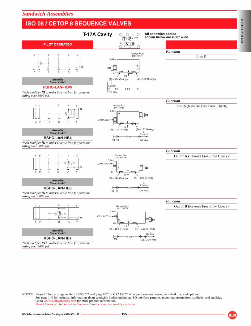
US Selected Assemblies Catalogue #999-901-192 195
Sandwich Assemblies
ISO 08 / CETOP 8 SEQUENCE VALVES
T-17A Cavity All sandwich bodiesshown below are 4.50” wide
PILOT OPERATED
FunctionIn to P
AssemblyModel Code*
RSHC-LAN-HBW*Add modifier /S to order Ductile Iron for pressure rating over 3000 psi.
FunctionIn to A (Reverse Free Flow Check)
AssemblyModel Code*
RSHC-LAN-HB4*Add modifier /S to order Ductile Iron for pressure rating over 3000 psi.
FunctionOut of A (Reverse Free Flow Check)
AssemblyModel Code*
RSHC-LAN-HB6*Add modifier /S to order Ductile Iron for pressure rating over 3000 psi.
FunctionOut of B (Reverse Free Flow Check)
AssemblyModel Code*
RSHC-LAN-HB7*Add modifier /S to order Ductile Iron for pressure rating over 3000 psi.
NOTES: Pages 20 for cartridge models RS*C-*** and page 102 for CX*A-*** show performance curves, technical tips, and options.See page 140 for technical information about sandwich bodies including ISO interface patterns, mounting instructions, studrods, and studkits.Go to www.sunhydraulics.com for more product information.Model Codes printed in red are Preferred Products and are readily available.
Y
X
G
P T B A
p t b a
X
x
Y
y
(2) – 114 O–rings (4) – 121 O–rings.25
1.75 Max.
LControl
5.94
Gauge Port1/4” NPTF
3.44
0
P T B A
p t b a
X
x
Y
y
G
.94 1.68 Max.
LControl
(2) – 114 O–rings (4) – 121 O–rings.25
5.94
.18
CXHA-XCN
3.44
0
Gauge Port1/4” NPTF
P T B A
p t b a
X
x
Y
y
G
.94 1.78 Max.
LControl
5.94
(2) – 114 O–rings (4) – 121 O–rings
Gauge Port1/4” NPTF
.25
.18
CXHA-XAN
3.44
0
P T B A
p t b a
X
x
Y
y
G
.915.94
(2) – 114 O–rings (4) – 121 O–rings.25
2.34 Max.
LControl
1.38
CXHA-XCN
Gauge Port1/4” NPTF
3.44
0
ISO
08/
CE
TO
P 8
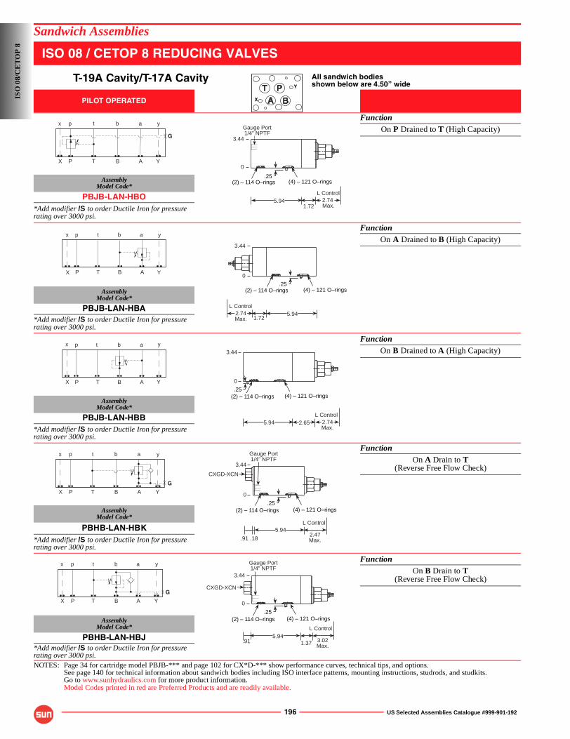
196 US Selected Assemblies Catalogue #999-901-192
Sandwich Assemblies
ISO 08 / CETOP 8 REDUCING VALVES
T-19A Cavity/T-17A Cavity All sandwich bodiesshown below are 4.50” wide
PILOT OPERATED
FunctionOn P Drained to T (High Capacity)
AssemblyModel Code*
PBJB-LAN-HBO*Add modifier /S to order Ductile Iron for pressure rating over 3000 psi.
FunctionOn A Drained to B (High Capacity)
AssemblyModel Code*
PBJB-LAN-HBA*Add modifier /S to order Ductile Iron for pressure rating over 3000 psi.
FunctionOn B Drained to A (High Capacity)
AssemblyModel Code*
PBJB-LAN-HBB*Add modifier /S to order Ductile Iron for pressure rating over 3000 psi.
FunctionOn A Drain to T
(Reverse Free Flow Check)
AssemblyModel Code*
PBHB-LAN-HBK*Add modifier /S to order Ductile Iron for pressure rating over 3000 psi.
FunctionOn B Drain to T
(Reverse Free Flow Check)
AssemblyModel Code*
PBHB-LAN-HBJ*Add modifier /S to order Ductile Iron for pressure rating over 3000 psi.NOTES: Page 34 for cartridge model PBJB-*** and page 102 for CX*D-*** show performance curves, technical tips, and options.
See page 140 for technical information about sandwich bodies including ISO interface patterns, mounting instructions, studrods, and studkits.Go to www.sunhydraulics.com for more product information.Model Codes printed in red are Preferred Products and are readily available.
Y
X
G
P T B A
p t b a
X
x
Y
y
(2) – 114 O–rings
2.74 Max.
L Control5.94
(4) – 121 O–rings.25
1.72
Gauge Port1/4” NPTF
3.44
0
P T B A
p t b a
X
x
Y
y
2.74Max.
L Control5.94
(2) – 114 O–rings (4) – 121 O–rings.25
1.72
3.44
0
P T B A
p t b a
X
x
Y
y
2.65
(2) – 114 O–rings (4) – 121 O–rings.25
2.74Max.
L Control5.94
3.44
0
p t b a
P T B AX
x
Y
y
G
(2) – 114 O–rings (4) – 121 O–rings
CXGD-XCN
.25
Gauge Port1/4” NPTF
.18.91
5.942.47Max.
L Control
3.44
0
P T B A
p t b a
X
x
Y
y
G
.915.94
(2) – 114 O–rings (4) – 121 O–rings
Gauge Port1/4” NPTF
CXGD-XCN
.25
3.02Max.
L Control
1.37
3.44
0
ISO
08/
CE
TO
P 8
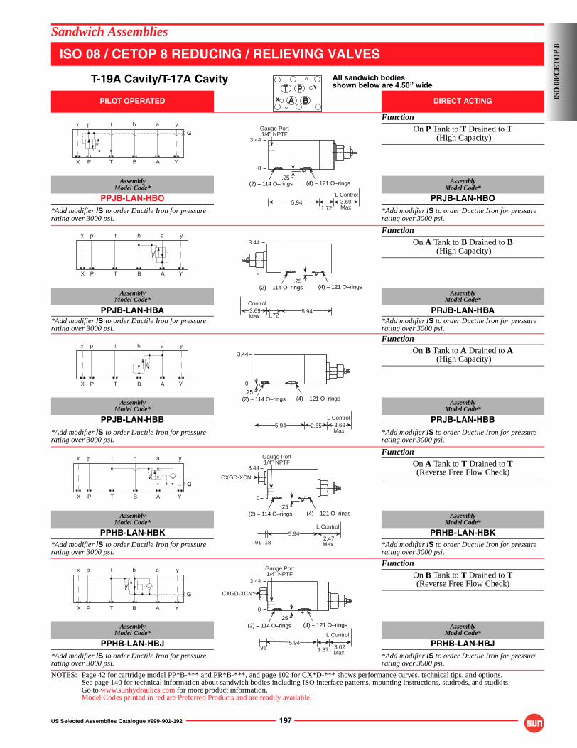
US Selected Assemblies Catalogue #999-901-192 197
Sandwich Assemblies
ISO 08 / CETOP 8 REDUCING / RELIEVING VALVES
T-19A Cavity/T-17A Cavity All sandwich bodiesshown below are 4.50” wide
PILOT OPERATED DIRECT ACTING
FunctionOn P Tank to T Drained to T
(High Capacity)
AssemblyModel Code*
AssemblyModel Code*
PPJB-LAN-HBO PRJB-LAN-HBO*Add modifier /S to order Ductile Iron for pressure rating over 3000 psi.
*Add modifier /S to order Ductile Iron for pressure rating over 3000 psi.
FunctionOn A Tank to B Drained to B
(High Capacity)
AssemblyModel Code*
AssemblyModel Code*
PPJB-LAN-HBA PRJB-LAN-HBA*Add modifier /S to order Ductile Iron for pressure rating over 3000 psi.
*Add modifier /S to order Ductile Iron for pressure rating over 3000 psi.
FunctionOn B Tank to A Drained to A
(High Capacity)
AssemblyModel Code*
AssemblyModel Code*
PPJB-LAN-HBB PRJB-LAN-HBB*Add modifier /S to order Ductile Iron for pressure rating over 3000 psi.
*Add modifier /S to order Ductile Iron for pressure rating over 3000 psi.
FunctionOn A Tank to T Drained to T(Reverse Free Flow Check)
AssemblyModel Code*
AssemblyModel Code*
PPHB-LAN-HBK PRHB-LAN-HBK*Add modifier /S to order Ductile Iron for pressure rating over 3000 psi.
*Add modifier /S to order Ductile Iron for pressure rating over 3000 psi.
FunctionOn B Tank to T Drained to T(Reverse Free Flow Check)
AssemblyModel Code*
AssemblyModel Code*
PPHB-LAN-HBJ PRHB-LAN-HBJ*Add modifier /S to order Ductile Iron for pressure rating over 3000 psi.
*Add modifier /S to order Ductile Iron for pressure rating over 3000 psi.
NOTES: Page 42 for cartridge model PP*B-*** and PR*B-***, and page 102 for CX*D-*** shows performance curves, technical tips, and options.See page 140 for technical information about sandwich bodies including ISO interface patterns, mounting instructions, studrods, and studkits.Go to www.sunhydraulics.com for more product information.Model Codes printed in red are Preferred Products and are readily available.
Y
X
G
P T B A
p t b a
X
x
Y
y
(2) – 114 O–rings
3.69 Max.
L Control5.94
(4) – 121 O–rings.25
1.72
Gauge Port1/4” NPTF
3.44
0
P T B A
p t b a
X
x
Y
y
3.69Max.
L Control5.94
(2) – 114 O–rings (4) – 121 O–rings.25
1.72
3.44
0
P T B A
p t b a
X
x
Y
y
2.65
(2) – 114 O–rings (4) – 121 O–rings.25
3.69Max.
L Control5.94
3.44
0
G
P T B A
p t b a
X
x
Y
y
(2) – 114 O–rings (4) – 121 O–rings
CXGD-XCN
.25
Gauge Port1/4” NPTF
.18.91
5.942.47Max.
L Control
3.44
0
G
P T B A
p t b a
X
x
Y
y
.915.94
(2) – 114 O–rings (4) – 121 O–rings
Gauge Port1/4” NPTF
CXGD-XCN
.25
3.02Max.
L Control
1.37
3.44
0
ISO
08/
CE
TO
P 8
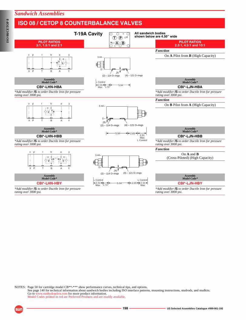
198 US Selected Assemblies Catalogue #999-901-192
Sandwich Assemblies
ISO 08 / CETOP 8 COUNTERBALANCE VALVES
T-19A Cavity All sandwich bodiesshown below are 4.50” wide
PILOT RATIOS3:1, 1.5:1 and 2:1
PILOT RATIOS2.3:1, 4.5:1 and 10:1
FunctionOn A Pilot from B (High Capacity)
AssemblyModel Code*
AssemblyModel Code*
CBI*-LHN-HBA CBI*-LJN-HBA*Add modifier /S to order Ductile Iron for pressure rating over 3000 psi.
*Add modifier /S to order Ductile Iron for pressure rating over 3000 psi.
FunctionOn B Pilot from A (High Capacity)
AssemblyModel Code*
AssemblyModel Code*
CBI*-LHN-HBB CBI*-LJN-HBB*Add modifier /S to order Ductile Iron for pressure rating over 3000 psi.
*Add modifier /S to order Ductile Iron for pressure rating over 3000 psi.
FunctionOn A and B
(Cross-Piloted) (High Capacity)
AssemblyModel Code*
AssemblyModel Code*
CBI*-LHN-HBY CBI*-LJN-HBY*Add modifier /S to order Ductile Iron for pressure rating over 3000 psi.
*Add modifier /S to order Ductile Iron for pressure rating over 3000 psi.
NOTES: Page 50 for cartridge model CB**-*** show performance curves, technical tips, and options.See page 140 for technical information about sandwich bodies including ISO interface patterns, mounting instructions, studrods, and studkits.Go to www.sunhydraulics.com for more product information.Model Codes printed in red are Preferred Products and are readily available.
Y
X
P T B A
p t b a
X
x
Y
y
.25
2.31Max.
L Control5.94
(2) – 114 O–rings (4) – 121 O–rings
1.72
3.44
0
P T B A
p t b a
X
x
Y
y
2.65
(2) – 114 O–rings (4) – 121 O–rings.25
2.31 Max.
L Control
5.94
3.44
0
P T B A
p t b a
X
x
Y
y
1.722.31Max.
L Control5.94
(2) – 114 O–rings (4) – 121 O–rings.25
2.65 2.31Max.
L Control
3.44
0
ISO
08/
CE
TO
P 8
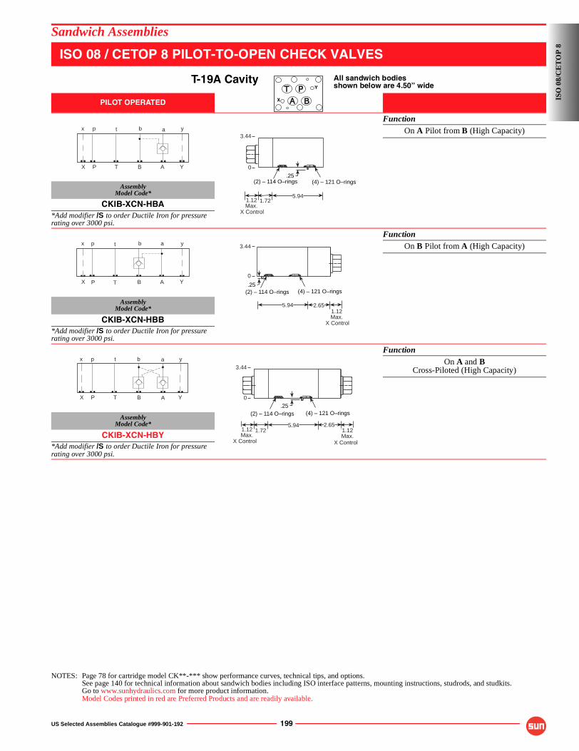
US Selected Assemblies Catalogue #999-901-192 199
Sandwich Assemblies
ISO 08 / CETOP 8 PILOT-TO-OPEN CHECK VALVES
T-19A Cavity All sandwich bodiesshown below are 4.50” wide
PILOT OPERATED
FunctionOn A Pilot from B (High Capacity)
AssemblyModel Code*
CKIB-XCN-HBA*Add modifier /S to order Ductile Iron for pressure rating over 3000 psi.
FunctionOn B Pilot from A (High Capacity)
AssemblyModel Code*
CKIB-XCN-HBB*Add modifier /S to order Ductile Iron for pressure rating over 3000 psi.
FunctionOn A and B
Cross-Piloted (High Capacity)
AssemblyModel Code*
CKIB-XCN-HBY*Add modifier /S to order Ductile Iron for pressure rating over 3000 psi.
NOTES: Page 78 for cartridge model CK**-*** show performance curves, technical tips, and options.See page 140 for technical information about sandwich bodies including ISO interface patterns, mounting instructions, studrods, and studkits.Go to www.sunhydraulics.com for more product information.Model Codes printed in red are Preferred Products and are readily available.
Y
X
P T B A
p t b a
X
x
Y
y
.25
1.12Max.
X Control
5.94
(2) – 114 O–rings (4) – 121 O–rings
1.72
3.44
0
P T B A
p t b a
X
x
Y
y
2.65
(2) – 114 O–rings (4) – 121 O–rings.25
1.12Max.
X Control
5.94
3.44
0
P T B A
p t b a
X
x
Y
y
1.721.12Max.
X Control
5.94
(2) – 114 O–rings (4) – 121 O–rings.25
2.651.12Max.
X Control
3.44
0
ISO
08/
CE
TO
P 8
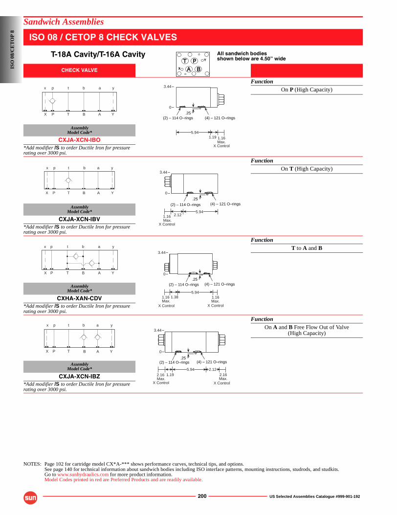
200 US Selected Assemblies Catalogue #999-901-192
Sandwich Assemblies
ISO 08 / CETOP 8 CHECK VALVES
T-18A Cavity/T-16A Cavity All sandwich bodiesshown below are 4.50” wide
CHECK VALVE
FunctionOn P (High Capacity)
AssemblyModel Code*
CXJA-XCN-IBO*Add modifier /S to order Ductile Iron for pressure rating over 3000 psi.
FunctionOn T (High Capacity)
AssemblyModel Code*
CXJA-XCN-IBV*Add modifier /S to order Ductile Iron for pressure rating over 3000 psi.
FunctionT to A and B
AssemblyModel Code*
CXHA-XAN-CDV*Add modifier /S to order Ductile Iron for pressure rating over 3000 psi.
FunctionOn A and B Free Flow Out of Valve
(High Capacity)
AssemblyModel Code*
CXJA-XCN-IBZ*Add modifier /S to order Ductile Iron for pressure rating over 3000 psi.
NOTES: Page 102 for cartridge model CX*A-*** shows performance curves, technical tips, and options.See page 140 for technical information about sandwich bodies including ISO interface patterns, mounting instructions, studrods, and studkits.Go to www.sunhydraulics.com for more product information.Model Codes printed in red are Preferred Products and are readily available.
Y
X
P T B A
p t b a
X
x
Y
y
1.19 1.16Max.
5.94
(2) – 114 O–rings (4) – 121 O–rings.25
3.44
0
X Control
P T B A
p t b a
X
x
Y
y
1.16 Max.
X Control
5.94
(2) – 114 O–rings (4) – 121 O–rings.25
2.12
3.44
0
P T B A
p t b a
X
x
Y
y
1.381.16 Max.
5.94
(2) – 114 O–rings (4) – 121 O–rings
1.16Max.
3.44
.250
X ControlX Control
P T B A
p t b a
X
x
Y
y
2.16 Max.
2.12
(2) – 114 O–rings (4) – 121 O–rings.25
2.16Max.
5.941.19
3.44
0
X ControlX Control
ISO
08/
CE
TO
P 8
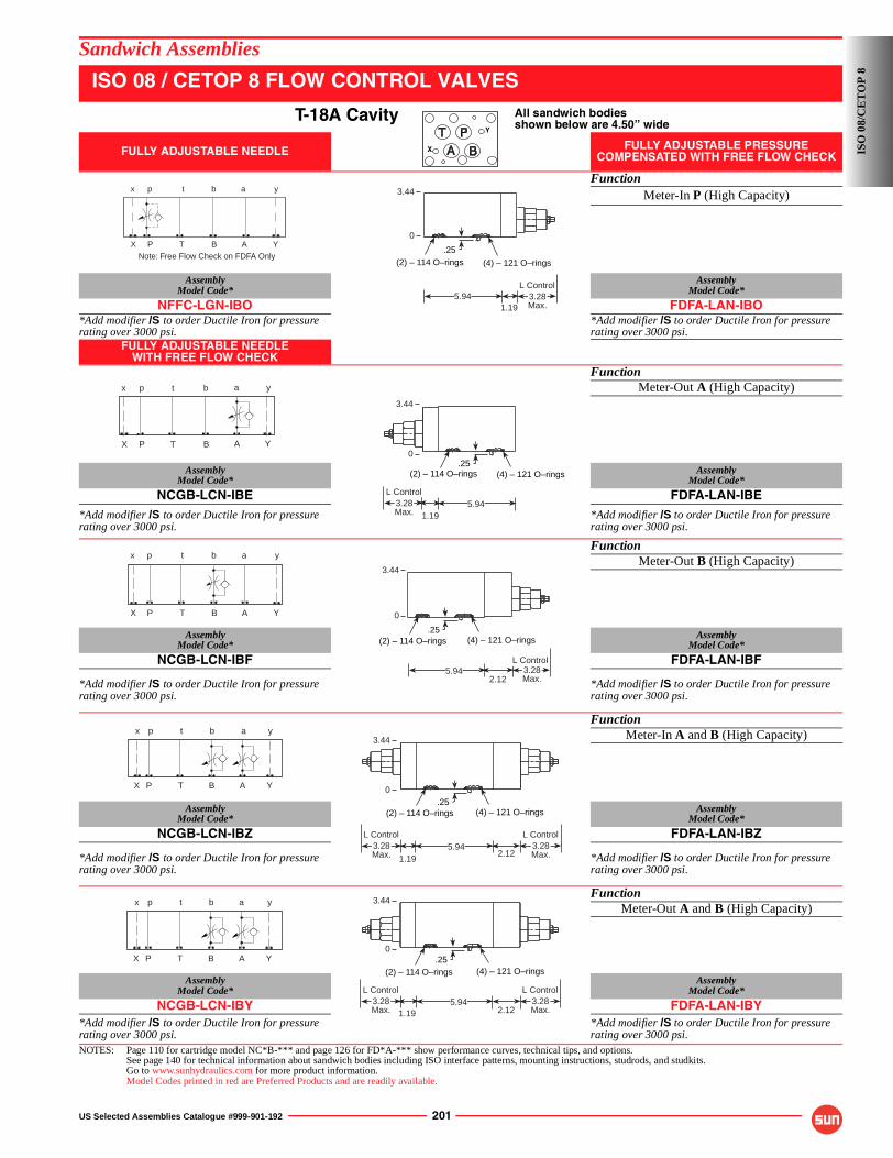
US Selected Assemblies Catalogue #999-901-192 201
Sandwich Assemblies
ISO 08 / CETOP 8 FLOW CONTROL VALVES
T-18A Cavity All sandwich bodiesshown below are 4.50” wide
FULLY ADJUSTABLE NEEDLE FULLY ADJUSTABLE PRESSURE COMPENSATED WITH FREE FLOW CHECK
FunctionMeter-In P (High Capacity)
AssemblyModel Code*
AssemblyModel Code*
NFFC-LGN-IBO FDFA-LAN-IBO*Add modifier /S to order Ductile Iron for pressure rating over 3000 psi.
*Add modifier /S to order Ductile Iron for pressure rating over 3000 psi.
FULLY ADJUSTABLE NEEDLE WITH FREE FLOW CHECK
FunctionMeter-Out A (High Capacity)
AssemblyModel Code*
AssemblyModel Code*
NCGB-LCN-IBE FDFA-LAN-IBE*Add modifier /S to order Ductile Iron for pressure rating over 3000 psi.
*Add modifier /S to order Ductile Iron for pressure rating over 3000 psi.
FunctionMeter-Out B (High Capacity)
AssemblyModel Code*
AssemblyModel Code*
NCGB-LCN-IBF FDFA-LAN-IBF
*Add modifier /S to order Ductile Iron for pressure rating over 3000 psi.
*Add modifier /S to order Ductile Iron for pressure rating over 3000 psi.
FunctionMeter-In A and B (High Capacity)
AssemblyModel Code*
AssemblyModel Code*
NCGB-LCN-IBZ FDFA-LAN-IBZ
*Add modifier /S to order Ductile Iron for pressure rating over 3000 psi.
*Add modifier /S to order Ductile Iron for pressure rating over 3000 psi.
FunctionMeter-Out A and B (High Capacity)
AssemblyModel Code*
AssemblyModel Code*
NCGB-LCN-IBY FDFA-LAN-IBY*Add modifier /S to order Ductile Iron for pressure rating over 3000 psi.
*Add modifier /S to order Ductile Iron for pressure rating over 3000 psi.
NOTES: Page 110 for cartridge model NC*B-*** and page 126 for FD*A-*** show performance curves, technical tips, and options.See page 140 for technical information about sandwich bodies including ISO interface patterns, mounting instructions, studrods, and studkits.Go to www.sunhydraulics.com for more product information.Model Codes printed in red are Preferred Products and are readily available.
Y
X
P T B A
p t b a
X
x
Y
y
Note: Free Flow Check on FDFA Only
3.28Max.
L Control
1.19
(2) – 114 O–rings (4) – 121 O–rings
.25
5.94
3.44
0
P T B A
p t b a
X
x
Y
y
1.193.28Max.
L Control5.94
(2) – 114 O–rings (4) – 121 O–rings.25
3.44
0
P T B A
p t b a
X
x
Y
y
3.28Max.
L Control5.94
(2) – 114 O–rings (4) – 121 O–rings.25
2.12
3.44
0
P T B A
p t b a
X
x
Y
y
1.19
3.28Max.
L Control5.94
(2) – 114 O–rings (4) – 121 O–rings.25
2.123.28Max.
L Control
3.44
0
P T B A
p t b a
X
x
Y
y
1.193.28Max.
L Control5.94
(2) – 114 O–rings (4) – 121 O–rings.25
3.28Max.
L Control
2.12
3.44
0
ISO
08/
CE
TO
P 8
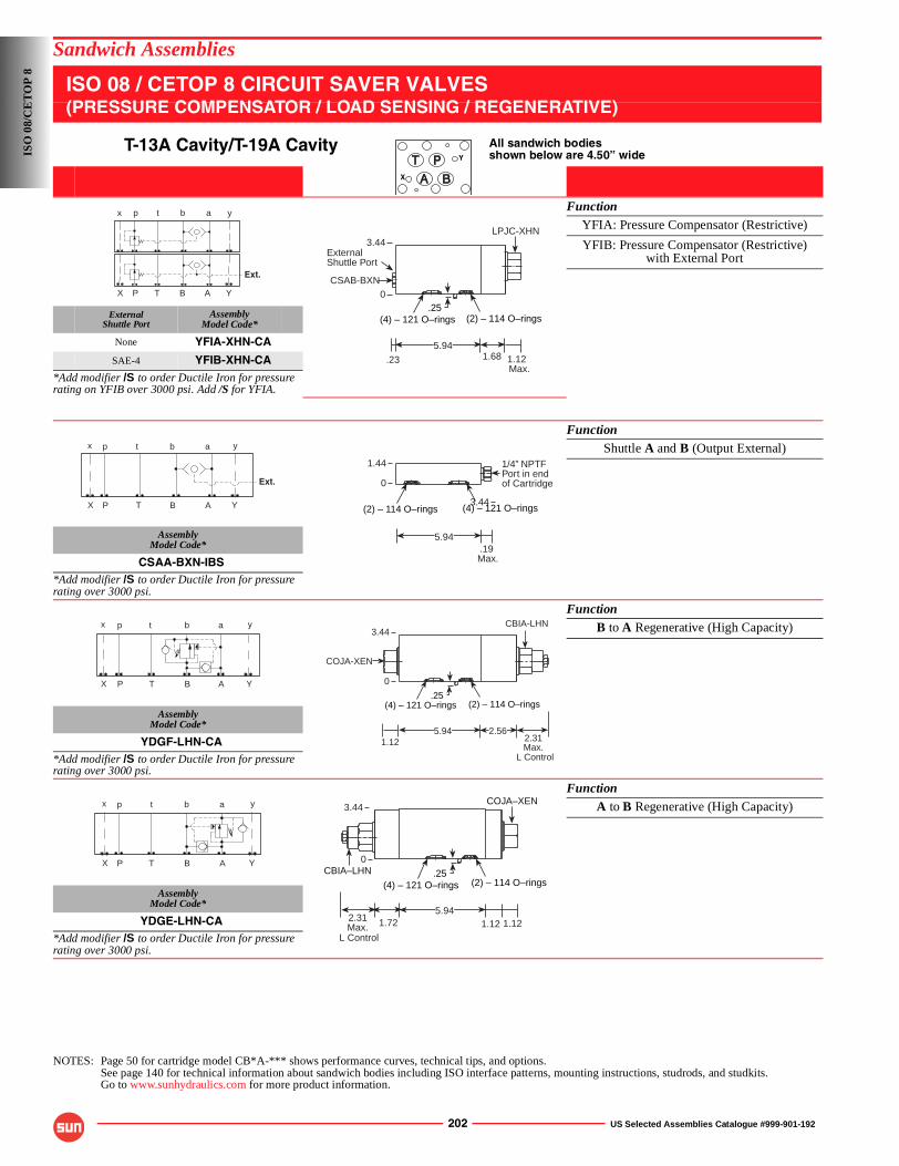
202 US Selected Assemblies Catalogue #999-901-192
Sandwich Assemblies
ISO 08 / CETOP 8 CIRCUIT SAVER VALVES(PRESSURE COMPENSATOR / LOAD SENSING / REGENERATIVE)
T-13A Cavity/T-19A Cavity All sandwich bodiesshown below are 4.50” wide
FunctionYFIA: Pressure Compensator (Restrictive)
YFIB: Pressure Compensator (Restrictive)with External Port
ExternalShuttle Port
AssemblyModel Code*
None YFIA-XHN-CA
SAE-4 YFIB-XHN-CA*Add modifier /S to order Ductile Iron for pressure rating on YFIB over 3000 psi. Add /S for YFIA.
FunctionShuttle A and B (Output External)
AssemblyModel Code*
CSAA-BXN-IBS*Add modifier /S to order Ductile Iron for pressure rating over 3000 psi.
FunctionB to A Regenerative (High Capacity)
AssemblyModel Code*
YDGF-LHN-CA*Add modifier /S to order Ductile Iron for pressure rating over 3000 psi.
FunctionA to B Regenerative (High Capacity)
AssemblyModel Code*
YDGE-LHN-CA*Add modifier /S to order Ductile Iron for pressure rating over 3000 psi.
NOTES: Page 50 for cartridge model CB*A-*** shows performance curves, technical tips, and options.See page 140 for technical information about sandwich bodies including ISO interface patterns, mounting instructions, studrods, and studkits.Go to www.sunhydraulics.com for more product information.
Y
X
P T B A
p t b a
X
x
Y
y
Ext.CSAB-BXN
(4) – 121 O–rings (2) – 114 O–rings
.23 1.12 Max.
5.941.68
LPJC-XHN3.44
.250
ExternalShuttle Port
P T B A
p t b a
X
x
Y
y
Ext.
.19 Max.
5.94
(2) – 114 O–rings (4) – 121 O–rings
1/4” NPTFPort in endof Cartridge
3.44
1.44
0
P T B A
p t b a
X
x
Y
y
1.12 2.31Max.
L Control
5.94
(4) – 121 O–rings (2) – 114 O–rings
2.56
COJA-XEN
CBIA-LHN3.44
.25
0
P T B A
p t b a
X
x
Y
y COJA–XEN
(4) – 121 O–rings (2) – 114 O–rings
2.31Max.
L Control
5.941.72 1.12 1.12
CBIA–LHN
3.44
.25
0
ISO
08/
CE
TO
P 8
US Selected Assemblies Catalogue #999-901-192 203
Assembly Type Page
CUSHION LOCK VALVES
Dual Load Control Applications Two Cavity with Checks Two Cavity with Checks and Shuttle Two Cavity with Anti-Cavitations Checks Two Cavity with Anti-Cavitations Checks and Shuttle
205207209211
HYDROSTATIC TRANSMISSION VALVESAND HOT OIL SHUTTLESHot Oil Shuttle and Relief Applications Inline/1.00” SAE Flange Port Inline 1.50” SAE Flange Port 2.00” SAE Flange Port
Hydrostatic Transmission Applications Inline 1.00” SAE Flange Port 1.25” SAE Flange Port 1.50”/2.00” SAE Flange Port
214215216217
218219220
LINE MOUNTED REGENERATIVE ASSEMBLIES
Pressure Sensitive Applications 15 GPM Maximum Regenerative Flow 10 GPM Maximum Regenerative Flow 30 GPM Maximum Regenerative Flow 20 GPM Maximum Total Flow with Load Holding Check Valve 60 GPM Maximum Regenerative Flow 50 GPM Maximum Regenerative Flow 120 GPM Maximum Regenerative Flow 240 GPM Maximum Regenerative Flow
224224225225226226227227
DIRECT MOTOR MOUNTED ASSEMBLIES
Char-Lynn S Series Motors Single/Dual Cross-port Relief and Single Counterbalance Applications Single/Dual Counterbalance and Dual Flow Control Applications Single Flow Control Applications Dual Cross-port Relief and Single Counterbalance Applications Single/Dual Counterbalance Applications Dual Cross-port Relief and Dual Counterbalance Applications
Danfoss (OMP/OMR Series and OMT Series) Single/Dual Cross-port Relief and Single Counterbalance Applications Single/Dual Counterbalance Applications (Shuttles) Dual Flow Control Applications Single/Dual Cross-port Relief and Single Counterbalance Applications Single/Dual Counterbalance Applications (Shuttles)
229230231232233234235
237238239240241242
Standard Assemblies
221
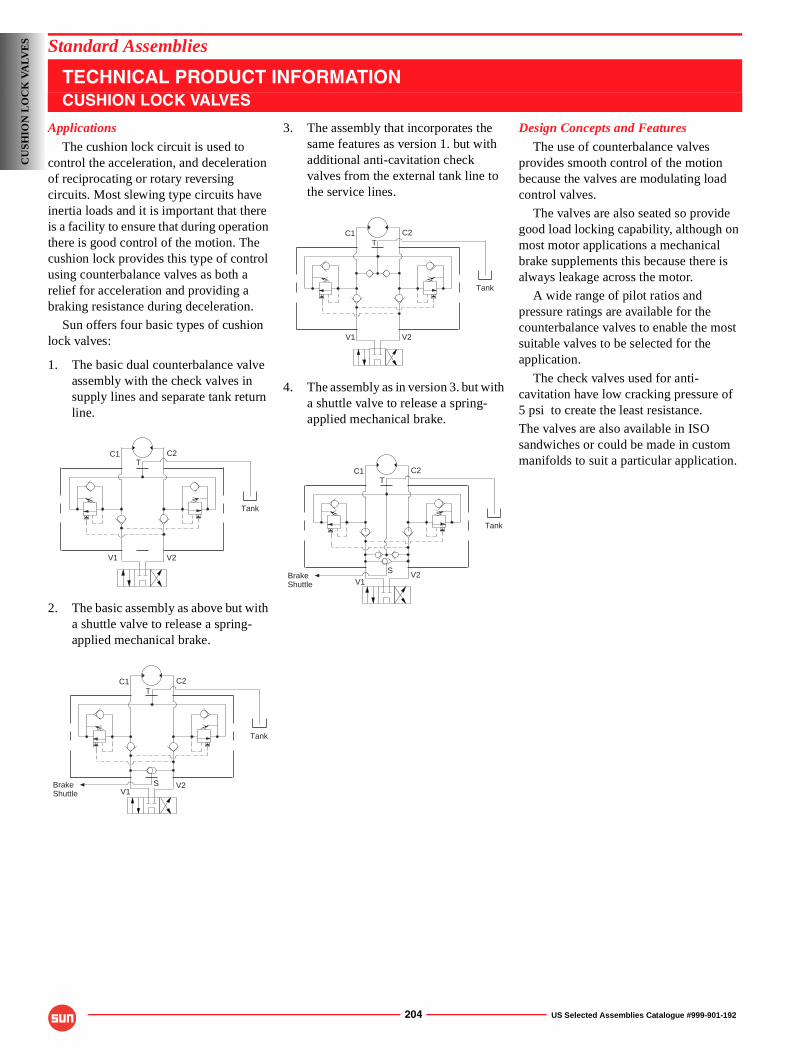
204 US Selected Assemblies Catalogue #999-901-192
Applications
The cushion lock circuit is used to control the acceleration, and deceleration of reciprocating or rotary reversing circuits. Most slewing type circuits have inertia loads and it is important that there is a facility to ensure that during operation there is good control of the motion. The cushion lock provides this type of control using counterbalance valves as both a relief for acceleration and providing a braking resistance during deceleration.
Sun offers four basic types of cushion lock valves:
1. The basic dual counterbalance valve assembly with the check valves in supply lines and separate tank return line.
2. The basic assembly as above but with a shuttle valve to release a spring-applied mechanical brake.
3. The assembly that incorporates the same features as version 1. but with additional anti-cavitation check valves from the external tank line to the service lines.
4. The assembly as in version 3. but with a shuttle valve to release a spring-applied mechanical brake.
Design Concepts and Features
The use of counterbalance valves provides smooth control of the motion because the valves are modulating load control valves.
The valves are also seated so provide good load locking capability, although on most motor applications a mechanical brake supplements this because there is always leakage across the motor.
A wide range of pilot ratios and pressure ratings are available for the counterbalance valves to enable the most suitable valves to be selected for the application.
The check valves used for anti-cavitation have low cracking pressure of5 psi to create the least resistance.
The valves are also available in ISO sandwiches or could be made in custom manifolds to suit a particular application.
C1 C2
V1 V2
Tank
T
C1 C2
V1V2
Tank
BrakeShuttle
T
S
C1 C2
V1 V2
Tank
T
C1 C2
V1V2
Tank
BrakeShuttle
T
S
CU
SHIO
N L
OC
K V
ALV
ES Standard Assemblies
TECHNICAL PRODUCT INFORMATIONCUSHION LOCK VALVES

US Selected Assemblies Catalogue #999-901-192 205
Standard Assemblies: Cushion Lock Valves
DUAL LOAD CONTROL APPLICATIONS(TWO CAVITY WITH CHECKS)
PILOT RATIOS1.5:1, 2:1, 2.3:1, 3:1, 4.5:1, 10:1
0-15 GPM Cavity T-11A
PortsC1, C2V1, V2
Port T AssemblyModel Code*
3/8” NPTF 1/2” NPTF CBC*-L*N-EMB
1/2” NPTF 1/2” NPTF CBC*-L*N-EMC
SAE-8 SAE-10 CBC*-L*N-EMJ
SAE-10 SAE-10 CBC*-L*N-EMK
*Add modifier /S to order Ductile Iron for pressure rating over 3000 psi.
0-30 GPM Cavity T-2A
PortsC1, C2V1, V2
Port T AssemblyModel Code*
1/2” NPTF 3/4” NPTF CBE*-L*N-BMC
3/4” NPTF 3/4” NPTF CBE*-L*N-BMD
SAE-10 SAE-12 CBE*-L*N-BMK
SAE-12 SAE-12 CBE*-L*N-BML
*Add modifier /S to order Ductile Iron for pressure rating over 3000 psi.
NOTES: Page 50 for cartridge model CB**-*** and page 102 for CX*D-*** shows performance curves, technical tips, and options.See page vii for technical information about line mount bodies including SAE flange pattern specifications.Consult your local Sun Distributor or the Sun Web Site for other port sizes available in the bodies shown above.Go to www.sunhydraulics.com for more product information and pricing.
C1 C2T
V1 V2
L Control
1.12
2.25.753.503.121.50.3800
00
.72
3.00
2.31
1.12
0.881.502.12
CXCD-XCN 2 places
Mounting Holes:.34 diameter through hole
2 places.
T.38
3.00
V1V2
C1 C2
1.28Max.
C1 C2T
V1 V2
3.75
2.87
1.25
.38
2.253.00 1.50 .750
0 0 .38 1.47 3.62 4.000
1.25
2.25 .75 0
CXED-XCN 2 places
Mounting Holes:.42 diameter through hole
2 places.
T
.66
C2C1
V2 V1 L Control1.57Max.
CU
SHIO
N L
OC
K V
AL
VE
S
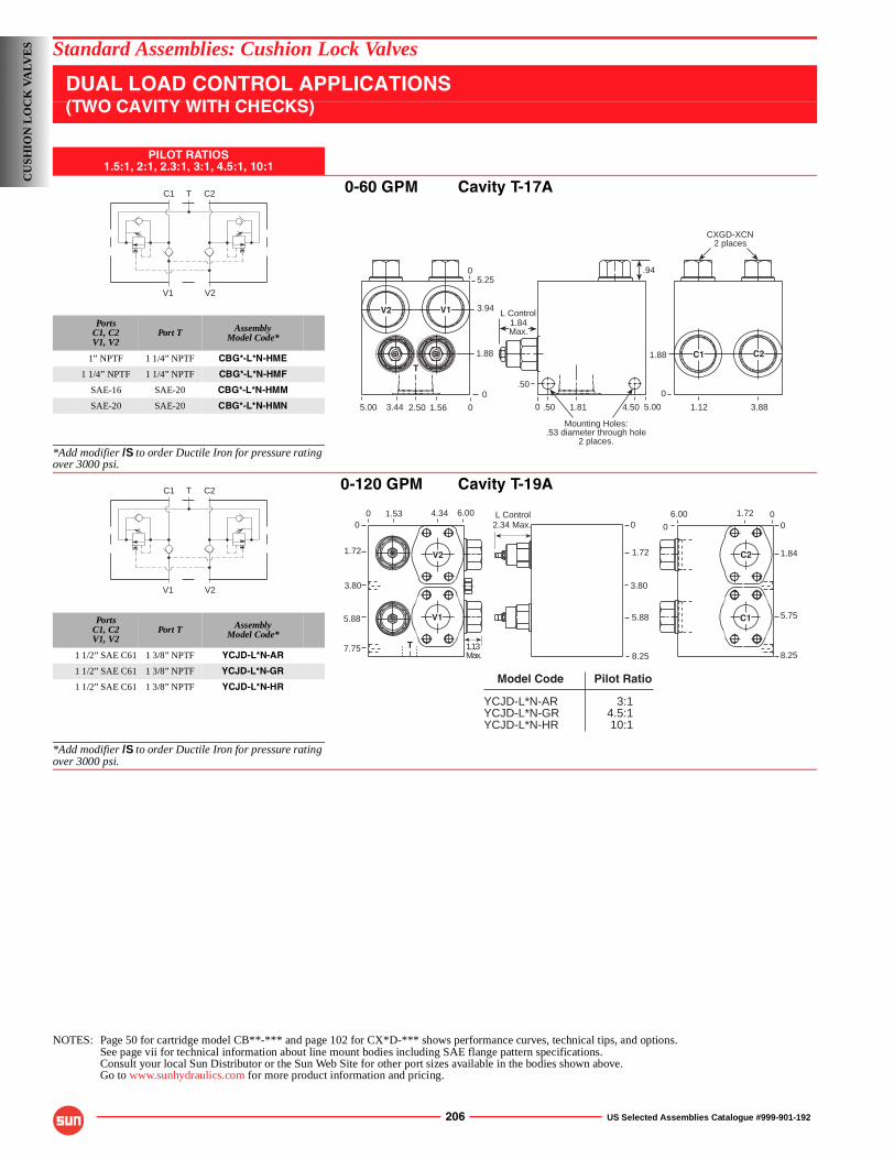
206 US Selected Assemblies Catalogue #999-901-192
Standard Assemblies: Cushion Lock Valves
DUAL LOAD CONTROL APPLICATIONS(TWO CAVITY WITH CHECKS)
PILOT RATIOS1.5:1, 2:1, 2.3:1, 3:1, 4.5:1, 10:1
0-60 GPM Cavity T-17A
PortsC1, C2V1, V2
Port T AssemblyModel Code*
1” NPTF 1 1/4” NPTF CBG*-L*N-HME
1 1/4” NPTF 1 1/4” NPTF CBG*-L*N-HMF
SAE-16 SAE-20 CBG*-L*N-HMM
SAE-20 SAE-20 CBG*-L*N-HMN
*Add modifier /S to order Ductile Iron for pressure rating over 3000 psi.
0-120 GPM Cavity T-19A
PortsC1, C2V1, V2
Port T AssemblyModel Code*
1 1/2” SAE C61 1 3/8” NPTF YCJD-L*N-AR
1 1/2” SAE C61 1 3/8” NPTF YCJD-L*N-GR
1 1/2” SAE C61 1 3/8” NPTF YCJD-L*N-HR
*Add modifier /S to order Ductile Iron for pressure rating over 3000 psi.
NOTES: Page 50 for cartridge model CB**-*** and page 102 for CX*D-*** shows performance curves, technical tips, and options.See page vii for technical information about line mount bodies including SAE flange pattern specifications.Consult your local Sun Distributor or the Sun Web Site for other port sizes available in the bodies shown above.Go to www.sunhydraulics.com for more product information and pricing.
C1 C2T
V1 V2
CXGD-XCN 2 places
00
0
1.88
3.881.124.501.81.50
.50
1.88
3.94
1.562.503.445.00 0 5.00
Mounting Holes:.53 diameter through hole
2 places.
5.250 .94
C2C1
L Control1.84Max.
T
V2 V1
C1 C2T
V1 V2
00
7.75
3.80
1.72
5.88
1.53 4.34 000
5.75
1.84
8.25
1.726.000
3.80
1.72
5.88
2.34 Max.L Control
8.25
6.00
1.13Max.
C2
C1
V2
V1
T
YCJD-L*N-ARYCJD-L*N-GRYCJD-L*N-HR
3:14.5:110:1
Model Code Pilot Ratio
CU
SHIO
N L
OC
K V
ALV
ES
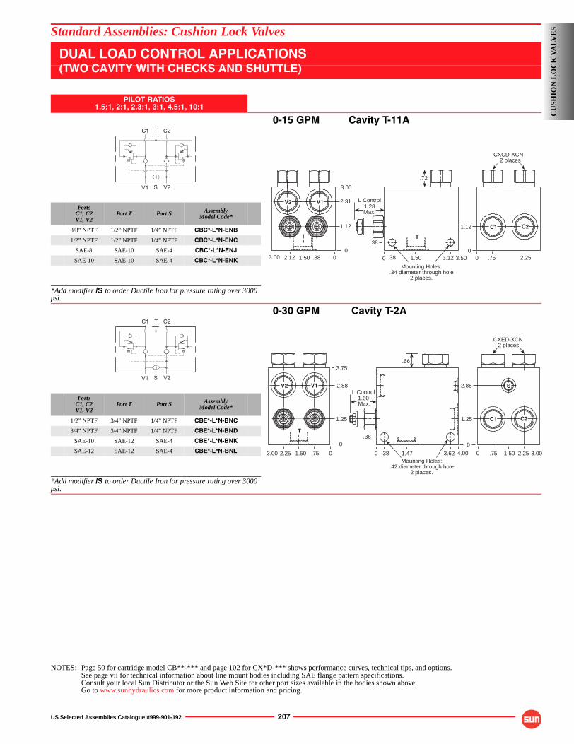
US Selected Assemblies Catalogue #999-901-192 207
Standard Assemblies: Cushion Lock Valves
DUAL LOAD CONTROL APPLICATIONS(TWO CAVITY WITH CHECKS AND SHUTTLE)
PILOT RATIOS1.5:1, 2:1, 2.3:1, 3:1, 4.5:1, 10:1
0-15 GPM Cavity T-11A
PortsC1, C2V1, V2
Port T Port S AssemblyModel Code*
3/8” NPTF 1/2” NPTF 1/4” NPTF CBC*-L*N-ENB
1/2” NPTF 1/2” NPTF 1/4” NPTF CBC*-L*N-ENC
SAE-8 SAE-10 SAE-4 CBC*-L*N-ENJ
SAE-10 SAE-10 SAE-4 CBC*-L*N-ENK
*Add modifier /S to order Ductile Iron for pressure rating over 3000 psi.
0-30 GPM Cavity T-2A
PortsC1, C2V1, V2
Port T Port S AssemblyModel Code*
1/2” NPTF 3/4” NPTF 1/4” NPTF CBE*-L*N-BNC
3/4” NPTF 3/4” NPTF 1/4” NPTF CBE*-L*N-BND
SAE-10 SAE-12 SAE-4 CBE*-L*N-BNK
SAE-12 SAE-12 SAE-4 CBE*-L*N-BNL
*Add modifier /S to order Ductile Iron for pressure rating over 3000 psi.
NOTES: Page 50 for cartridge model CB**-*** and page 102 for CX*D-*** shows performance curves, technical tips, and options.See page vii for technical information about line mount bodies including SAE flange pattern specifications.Consult your local Sun Distributor or the Sun Web Site for other port sizes available in the bodies shown above.Go to www.sunhydraulics.com for more product information and pricing.
V1 S V2
C1 T C2
L Control
1.12
2.25.753.503.121.50.3800
00
.72
3.00
2.31
1.12
0.881.502.12
CXCD-XCN 2 places
Mounting Holes:.34 diameter through hole
2 places.
T.38
3.00
V1V2
C1 C2
1.28Max.
V1 S V2
C1 T C2
Mounting Holes:.42 diameter through hole
2 places.
.663.75
0.38
1.25
2.88
3.00 2.25 1.50 .75 0 0
0
4.00 01.47.38 3.62
1.25
2.88
.75 2.251.50 3.00
S
C1 C2
CXED-XCN 2 places
L Control1.60 Max.
T
V1V2
CU
SHIO
N L
OC
K V
AL
VE
S
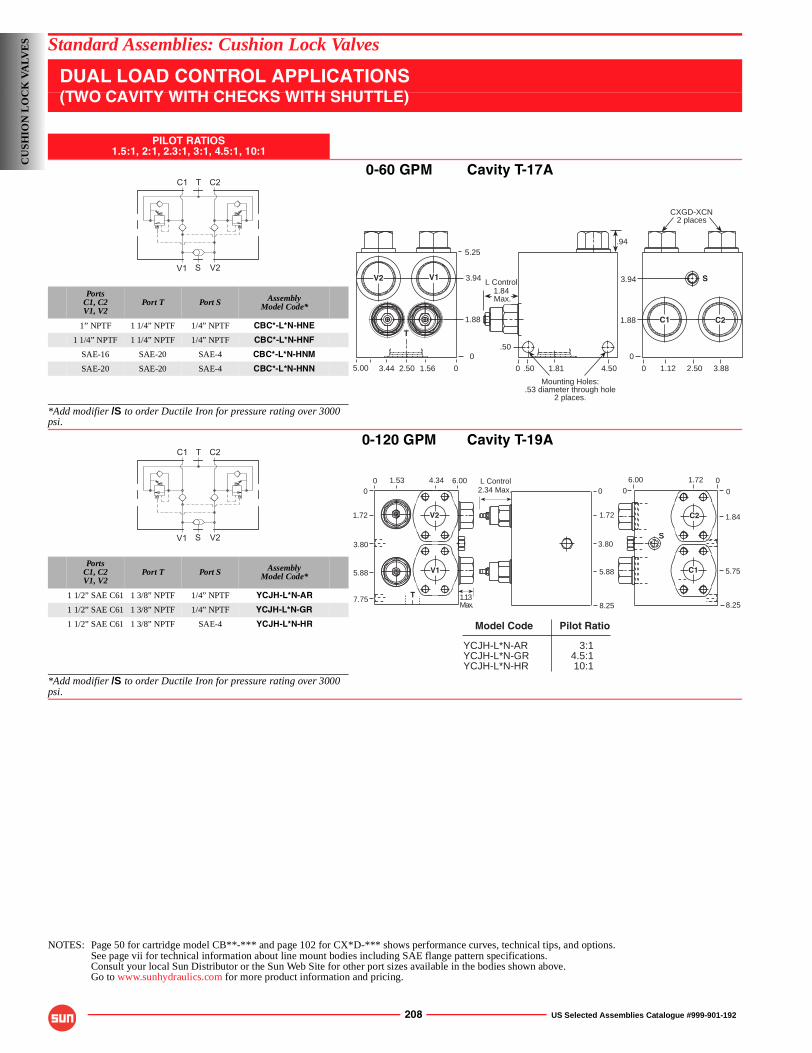
208 US Selected Assemblies Catalogue #999-901-192
Standard Assemblies: Cushion Lock Valves
DUAL LOAD CONTROL APPLICATIONS(TWO CAVITY WITH CHECKS WITH SHUTTLE)
PILOT RATIOS1.5:1, 2:1, 2.3:1, 3:1, 4.5:1, 10:1
0-60 GPM Cavity T-17A
PortsC1, C2V1, V2
Port T Port S AssemblyModel Code*
1” NPTF 1 1/4” NPTF 1/4” NPTF CBC*-L*N-HNE
1 1/4” NPTF 1 1/4” NPTF 1/4” NPTF CBC*-L*N-HNF
SAE-16 SAE-20 SAE-4 CBC*-L*N-HNM
SAE-20 SAE-20 SAE-4 CBC*-L*N-HNN
*Add modifier /S to order Ductile Iron for pressure rating over 3000 psi.
0-120 GPM Cavity T-19A
PortsC1, C2V1, V2
Port T Port S AssemblyModel Code*
1 1/2” SAE C61 1 3/8” NPTF 1/4” NPTF YCJH-L*N-AR
1 1/2” SAE C61 1 3/8” NPTF 1/4” NPTF YCJH-L*N-GR
1 1/2” SAE C61 1 3/8” NPTF SAE-4 YCJH-L*N-HR
*Add modifier /S to order Ductile Iron for pressure rating over 3000 psi.
NOTES: Page 50 for cartridge model CB**-*** and page 102 for CX*D-*** shows performance curves, technical tips, and options.See page vii for technical information about line mount bodies including SAE flange pattern specifications.Consult your local Sun Distributor or the Sun Web Site for other port sizes available in the bodies shown above.Go to www.sunhydraulics.com for more product information and pricing.
V1 S V2
C1 T C2
Mounting Holes:.53 diameter through hole
2 places.
5.25
CXGD-XCN 2 places
0
0 01.562.503.445.00
3.94
1.88
.50
.50 1.81 4.50
0
0
1.88
1.12 2.50 3.88
3.94
.94
V2 V1
T
C2C1
SL Control1.84 Max.
V1 S V2
C1 T C2
00
7.75
3.80
1.72
5.88
1.53 4.34 0
00
5.75
1.84
8.25
1.726.00
SS
0
3.80
1.72
5.88
2.34 Max.L Control
8.25
6.00
1.13Max.
V1
V2 C2
C1
T
YCJH-L*N-ARYCJH-L*N-GRYCJH-L*N-HR
3:14.5:110:1
Model Code Pilot Ratio
CU
SHIO
N L
OC
K V
ALV
ES
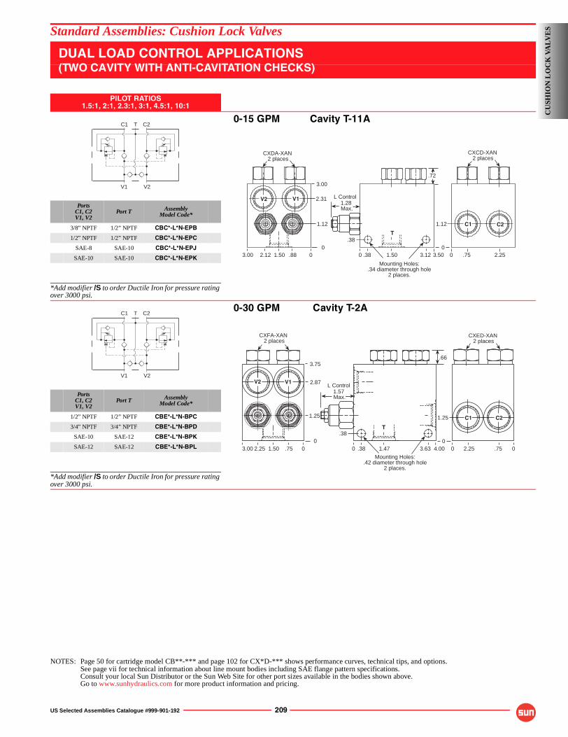
US Selected Assemblies Catalogue #999-901-192 209
Standard Assemblies: Cushion Lock Valves
DUAL LOAD CONTROL APPLICATIONS(TWO CAVITY WITH ANTI-CAVITATION CHECKS)
PILOT RATIOS1.5:1, 2:1, 2.3:1, 3:1, 4.5:1, 10:1
0-15 GPM Cavity T-11A
PortsC1, C2V1, V2
Port T AssemblyModel Code*
3/8” NPTF 1/2” NPTF CBC*-L*N-EPB
1/2” NPTF 1/2” NPTF CBC*-L*N-EPC
SAE-8 SAE-10 CBC*-L*N-EPJ
SAE-10 SAE-10 CBC*-L*N-EPK
*Add modifier /S to order Ductile Iron for pressure rating over 3000 psi.
0-30 GPM Cavity T-2A
PortsC1, C2V1, V2
Port T AssemblyModel Code*
1/2” NPTF 1/2” NPTF CBE*-L*N-BPC
3/4” NPTF 3/4” NPTF CBE*-L*N-BPD
SAE-10 SAE-12 CBE*-L*N-BPK
SAE-12 SAE-12 CBE*-L*N-BPL
*Add modifier /S to order Ductile Iron for pressure rating over 3000 psi.
NOTES: Page 50 for cartridge model CB**-*** and page 102 for CX*D-*** shows performance curves, technical tips, and options.See page vii for technical information about line mount bodies including SAE flange pattern specifications.Consult your local Sun Distributor or the Sun Web Site for other port sizes available in the bodies shown above.Go to www.sunhydraulics.com for more product information and pricing.
C1 C2T
V1 V2
Mounting Holes:.34 diameter through hole
2 places.
3.00
CXDA-XAN 2 places
00 0.881.502.123.00 .38 1.50 3.12 3.50
00
2.31
1.12
.38
1.12
.75 2.25
T
.72
C1 C2
CXCD-XAN 2 places
V2 V1 L Control1.28 Max.
C1 C2T
V1 V2
Mounting Holes:.42 diameter through hole
2 places.
3.75
CXFA-XAN 2 places
00 0
CXED-XAN 2 places
V2 V1
.751.502.253.00 .38 1.47 3.63 4.000
0
2.87
1.25
.38
1.25 C1 C2
2.25 .75 0
.66
T
L Control1.57 Max.
CU
SHIO
N L
OC
K V
AL
VE
S
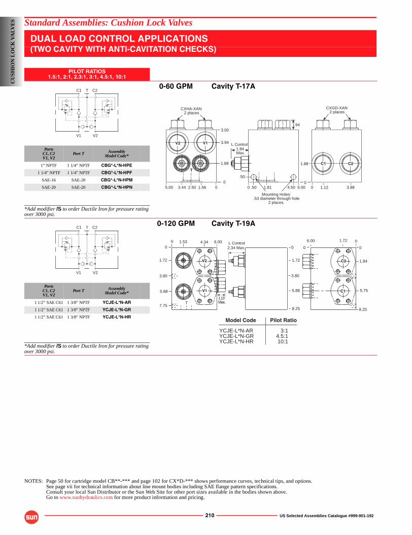
210 US Selected Assemblies Catalogue #999-901-192
Standard Assemblies: Cushion Lock Valves
DUAL LOAD CONTROL APPLICATIONS(TWO CAVITY WITH ANTI-CAVITATION CHECKS)
PILOT RATIOS1.5:1, 2:1, 2.3:1, 3:1, 4.5:1, 10:1
0-60 GPM Cavity T-17A
PortsC1, C2V1, V2
Port T AssemblyModel Code*
1” NPTF 1 1/4” NPTF CBG*-L*N-HPE
1 1/4” NPTF 1 1/4” NPTF CBG*-L*N-HPF
SAE-16 SAE-20 CBG*-L*N-HPM
SAE-20 SAE-20 CBG*-L*N-HPN
*Add modifier /S to order Ductile Iron for pressure rating over 3000 psi.
0-120 GPM Cavity T-19A
PortsC1, C2V1, V2
Port T AssemblyModel Code*
1 1/2” SAE C61 1 3/8” NPTF YCJE-L*N-AR
1 1/2” SAE C61 1 3/8” NPTF YCJE-L*N-GR
1 1/2” SAE C61 1 3/8” NPTF YCJE-L*N-HR
*Add modifier /S to order Ductile Iron for pressure rating over 3000 psi.
NOTES: Page 50 for cartridge model CB**-*** and page 102 for CX*D-*** shows performance curves, technical tips, and options.See page vii for technical information about line mount bodies including SAE flange pattern specifications.Consult your local Sun Distributor or the Sun Web Site for other port sizes available in the bodies shown above.Go to www.sunhydraulics.com for more product information and pricing.
C1 C2T
V1 V2
Mounting Holes:.53 diameter through hole
2 places.
3.00
CXGD-XAN 2 places
00 0
CXHA-XAN 2 places
05.00 04.501.81.50 1.12 3.88
1.881.88
.50
3.94
1.562.503.445.00
.94
V2 V1
T
C1 C2
L Control1.84 Max.
C1 C2T
V1 V2
00
7.75
3.80
1.72
5.88
1.53 4.34
T
0
00
5.75
1.84
8.25
1.726.00
0
3.80
1.72
5.88
8.25
2.34 Max.L Control6.00
1.13Max.
C2
C1V1
V2
YCJE-L*N-ARYCJE-L*N-GRYCJE-L*N-HR
3:14.5:110:1
Model Code Pilot Ratio
CU
SHIO
N L
OC
K V
ALV
ES
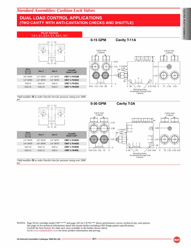
US Selected Assemblies Catalogue #999-901-192 211
Standard Assemblies: Cushion Lock Valves
DUAL LOAD CONTROL APPLICATIONS(TWO CAVITY WITH ANTI-CAVITATION CHECKS AND SHUTTLE)
PILOT RATIOS1.5:1, 2:1, 2.3:1, 3:1, 4.5:1, 10:1
0-15 GPM Cavity T-11A
PortsC1, C2V1, V2
Port T Port S AssemblyModel Code*
3/8” NPTF 1/2” NPTF 1/4” NPTF CBC*-L*N-EQB
1/2” NPTF 1/2” NPTF 1/4” NPTF CBC*-L*N-EQC
SAE-8 SAE-10 SAE-4 CBC*-L*N-EQJ
SAE-10 SAE-10 SAE-4 CBC*-L*N-EQK
*Add modifier /S to order Ductile Iron for pressure rating over 3000 psi.
0-30 GPM Cavity T-2A
PortsC1, C2V1, V2
Port T Port S AssemblyModel Code*
1/2” NPTF 3/4” NPTF 1/4” NPTF CBE*-L*N-BQC
3/4” NPTF 3/4” NPTF 1/4” NPTF CBE*-L*N-BQD
SAE-10 SAE-12 SAE-4 CBE*-L*N-BQK
SAE-12 SAE-12 SAE-4 CBE*-L*N-BQL
*Add modifier /S to order Ductile Iron for pressure rating over 3000 psi.
NOTES: Page 50 for cartridge model CB**-*** and page 102 for CX*D-*** shows performance curves, technical tips, and options.See page vii for technical information about line mount bodies including SAE flange pattern specifications.Consult the Sun Factory for other port sizes available in the bodies shown above.Go to www.sunhydraulics.com for more product information and pricing.
C1 C2T
V1 V2S
Mounting Holes:.34 diameter through hole
2 places.
3.00
CXCD-XAN 2 places
00 0.881.502.123.00 .38 1.50 3.12 3.50
1.12
.38
2.31
CXDA-XAN 2 places
0 .75 1.50 2.250
1.12
2.31V2 V1
T
.72
S
C1 C2
L Control1.28 Max.
C1 C2T
V1 V2S
Mounting Holes:.42 diameter through hole
2 places.
.663.75
CXFA-XAN 2 places
0
0 0.751.502.253.00
2.88
1.25
.38 1.47 3.62 4.000
0
.38
1.25
2.88
.75 1.50 2.25 3.00
CXED-XAN 2 places
S
C1 C2
L Control1.60 Max.
CU
SHIO
N L
OC
K V
AL
VE
S
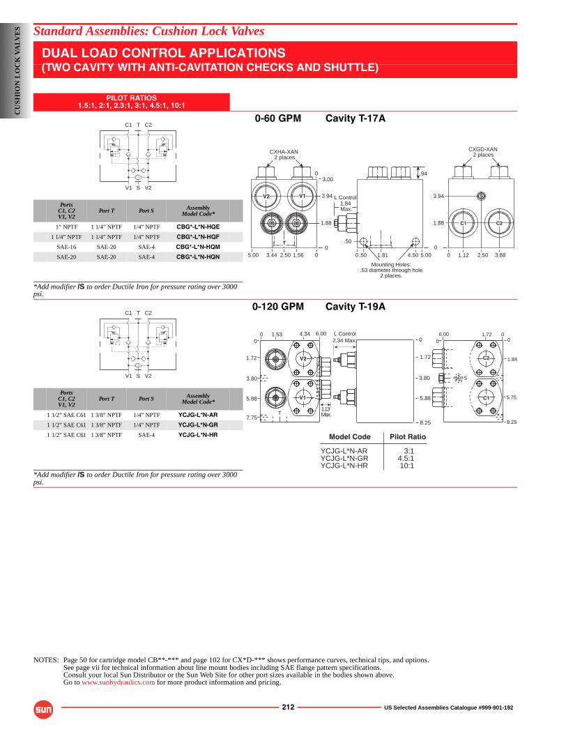
212 US Selected Assemblies Catalogue #999-901-192
Standard Assemblies: Cushion Lock Valves
DUAL LOAD CONTROL APPLICATIONS(TWO CAVITY WITH ANTI-CAVITATION CHECKS AND SHUTTLE)
PILOT RATIOS1.5:1, 2:1, 2.3:1, 3:1, 4.5:1, 10:1
0-60 GPM Cavity T-17A
PortsC1, C2V1, V2
Port T Port S AssemblyModel Code*
1” NPTF 1 1/4” NPTF 1/4” NPTF CBG*-L*N-HQE
1 1/4” NPTF 1 1/4” NPTF 1/4” NPTF CBG*-L*N-HQF
SAE-16 SAE-20 SAE-4 CBG*-L*N-HQM
SAE-20 SAE-20 SAE-4 CBG*-L*N-HQN
*Add modifier /S to order Ductile Iron for pressure rating over 3000 psi.
0-120 GPM Cavity T-19A
PortsC1, C2V1, V2
Port T Port S AssemblyModel Code*
1 1/2” SAE C61 1 3/8” NPTF 1/4” NPTF YCJG-L*N-AR
1 1/2” SAE C61 1 3/8” NPTF 1/4” NPTF YCJG-L*N-GR
1 1/2” SAE C61 1 3/8” NPTF SAE-4 YCJG-L*N-HR
*Add modifier /S to order Ductile Iron for pressure rating over 3000 psi.
NOTES: Page 50 for cartridge model CB**-*** and page 102 for CX*D-*** shows performance curves, technical tips, and options.See page vii for technical information about line mount bodies including SAE flange pattern specifications.Consult your local Sun Distributor or the Sun Web Site for other port sizes available in the bodies shown above.Go to www.sunhydraulics.com for more product information and pricing.
C1 C2T
V1 V2S
Mounting Holes:.53 diameter through hole
2 places.
3.00
CXGD-XAN 2 places
00 01.562.503.445.00
1.88
3.94
.50
0
.50 1.81 4.500
5.00 0
1.88
3.94
CXHA-XAN 2 places
1.12 2.50 3.88
.94
S
C2C1
T
V2 V1 L Control1.84 Max.
C1 C2T
V1 V2S
00
7.75
3.80
1.72
5.88
1.53 4.34 000
5.75
1.84
8.25
1.726.00
S
2.34 Max.
T
0
3.80
1.72
5.88
8.25
L Control6.00
1.13Max.
C2
C1
V2
V1
YCJG-L*N-ARYCJG-L*N-GRYCJG-L*N-HR
3:14.5:110:1
Model Code Pilot Ratio
CU
SHIO
N L
OC
K V
ALV
ES
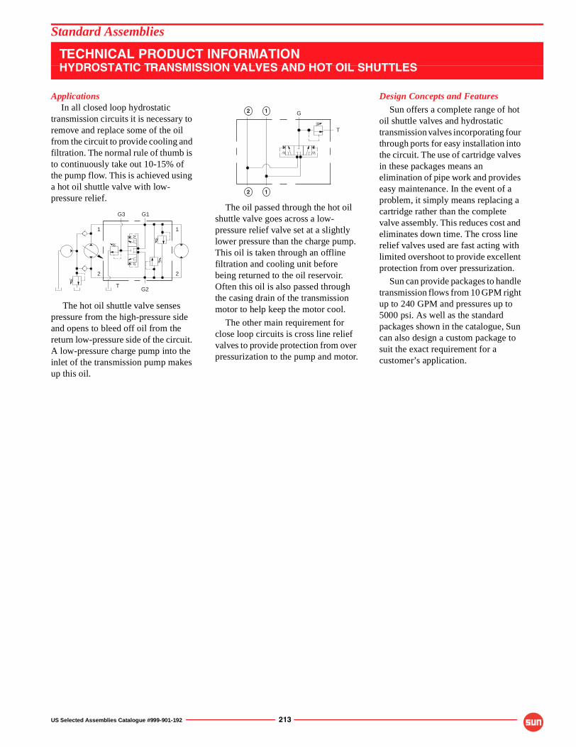
US Selected Assemblies Catalogue #999-901-192 213
Standard Assemblies
TECHNICAL PRODUCT INFORMATIONHYDROSTATIC TRANSMISSION VALVES AND HOT OIL SHUTTLES
ApplicationsIn all closed loop hydrostatic
transmission circuits it is necessary to remove and replace some of the oil from the circuit to provide cooling and filtration. The normal rule of thumb is to continuously take out 10-15% of the pump flow. This is achieved using a hot oil shuttle valve with low-pressure relief.
The hot oil shuttle valve senses pressure from the high-pressure side and opens to bleed off oil from the return low-pressure side of the circuit. A low-pressure charge pump into the inlet of the transmission pump makes up this oil.
The oil passed through the hot oil shuttle valve goes across a low-pressure relief valve set at a slightly lower pressure than the charge pump. This oil is taken through an offline filtration and cooling unit before being returned to the oil reservoir. Often this oil is also passed through the casing drain of the transmission motor to help keep the motor cool.
The other main requirement for close loop circuits is cross line relief valves to provide protection from over pressurization to the pump and motor.
Design Concepts and Features
Sun offers a complete range of hot oil shuttle valves and hydrostatic transmission valves incorporating four through ports for easy installation into the circuit. The use of cartridge valves in these packages means an elimination of pipe work and provides easy maintenance. In the event of a problem, it simply means replacing a cartridge rather than the complete valve assembly. This reduces cost and eliminates down time. The cross line relief valves used are fast acting with limited overshoot to provide excellent protection from over pressurization.
Sun can provide packages to handle transmission flows from 10 GPM right up to 240 GPM and pressures up to 5000 psi. As well as the standard packages shown in the catalogue, Sun can also design a custom package to suit the exact requirement for a customer’s application.
2
11
2
G2
G1G3
T
T
G2 1
12
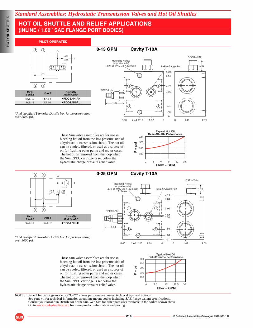
214 US Selected Assemblies Catalogue #999-901-192
Standard Assemblies: Hydrostatic Transmission Valves and Hot Oil Shuttles
HOT OIL SHUTTLE AND RELIEF APPLICATIONS(INLINE / 1.00” SAE FLANGE PORT BODIES)
PILOT OPERATED
0-13 GPM Cavity T-10A
Ports1 and 2 Port T Assembly
Model Code*
SAE-10 SAE-8 XRDC-LNN-AKSAE-12 SAE-8 XRDC-LNN-AL
*Add modifier /S to order Ductile Iron for pressure rating over 3000 psi.
0-25 GPM Cavity T-10A
Ports1 and 2 Port T Assembly
Model Code*
SAE-12 SAE-10 XRFC-LNN-AL
*Add modifier /S to order Ductile Iron for pressure rating over 3000 psi.
NOTES: Page 2 for cartridge model RP*C-*** shows performance curves, technical tips, and options.See page vii for technical information about line mount bodies including SAE flange pattern specifications.Consult your local Sun Distributor or the Sun Web Site for other port sizes available in the bodies shown above.Go to www.sunhydraulics.com for more product information and pricing.
T
G2 1
12
3.50 1.122.122.44 0
0
1.84
RPEC-LNN
SAE-6 Gauge Port
3.62
2.75
2.16
.91
.38
0 1.11 2.75
4.00
DSCH-XHN
1.08
1
2
1
2
T G
Mounting Holes:(opposite side)
.375-16 UNC-2B x.62 deep
Flow = GPM
400
3 6 9 12
300
100
200
150
Typical Hot OilRelief/Shuttle Performance
P =
psi
These Sun valve assemblies are for use inbleeding hot oil from the low pressure side ofa hydrostatic transmission circuit. The hot oilcan be cooled, filtered, or used as a source of oil for flushing other pump and motor cases.The hot oil is removed from the loop whenthe Sun RPEC cartridge is set below thehydrostatic charge pressure relief valve.
12
12
T
G
1.94
DSEH-XHN
1.382.664.00
SAE-6 Gauge Port
2.25 0
0
0
.34
1.91
3.00
.94
1.97
3.84
4.19
1.09 3.00
RPEC-LNN
1.25
T G
1 1
2 2
Mounting Holes:(opposite side)
.375-16 UNC-2B x .62 deep.2 places.
Flow = GPM
P =
psi
500
200
7.5 15 22.5
400
30
300
100
0
Typical Hot OilRelief/Shuttle PerformanceThese Sun valve assemblies are for use in
bleeding hot oil from the low pressure side ofa hydrostatic transmission circuit. The hot oilcan be cooled, filtered, or used as a source of oil for flushing other pump and motor cases.The hot oil is removed from the loop whenthe Sun RPEC cartridge is set below thehydrostatic charge pressure relief valve.
HO
T O
IL S
HU
TT
LE
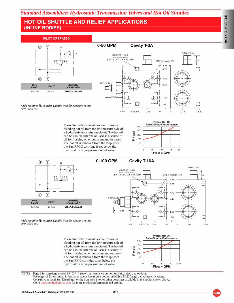
US Selected Assemblies Catalogue #999-901-192 215
Standard Assemblies: Hydrostatic Transmission Valves and Hot Oil Shuttles
HOT OIL SHUTTLE AND RELIEF APPLICATIONS(INLINE BODIES)
PILOT OPERATED
0-50 GPM Cavity T-3A
Ports1 and 2 Port T Assembly
Model Code*
SAE-16 SAE-12 XRHC-LNN-AM
*Add modifier /S to order Ductile Iron for pressure rating over 3000 psi.
0-100 GPM Cavity T-16A
Ports1 and 2 Port T Assembly
Model Code*
SAE-20 SAE-16 XRJC-LNN-AM
*Add modifier /S to order Ductile Iron for pressure rating over 3000 psi.
NOTES: Page 2 for cartridge model RP*C-*** shows performance curves, technical tips, and options.See page vii for technical information about line mount bodies including SAE flange pattern specifications.Consult your local Sun Distributor or the Sun Web Site for other port sizes available in the bodies shown above.Go to www.sunhydraulics.com for more product information and pricing.
12
G
T
12
03.314.50
RPGC-LNN
1.56SAE-6 Gauge Port
2.06
3.00 1.81
DSGH-XHN
0
.50
2.69
1.52
3.88
4.75
5.25
0 1.38 3.50
T G
2 2
1 1
Mounting Holes:(opposite side)
.375-16 UNC-2B x.62 deep
Flow = GPM
P =
psi
500
200
15 30 45
400
60
300
100
0
Typical Hot OilRelief/Shuttle PerformanceThese Sun valve assemblies are for use in
bleeding hot oil from the low pressure side ofa hydrostatic transmission circuit. The hot oilcan be cooled, filtered, or used as a source of oil for flushing other pump and motor cases.The hot oil is removed from the loop whenthe Sun RPGC cartridge is set below thehydrostatic charge pressure relief valve.
G
T
12
12
2.444.004.56
RPIC-LNN
1.94SAE-6 Gauge Port
2.38
6.00 0
0
0
.50
1.69
3.17
4.72
5.75
6.25
1.50 4.50
T G
DSIH-XHN
22
1 1
Mounting Holes:(opposite side)
.375-16 UNC-2B x.62 deep
Flow = GPM
P =
psi
500
200
30 60 90
400
120
300
100
0
Typical Hot OilRelief/Shuttle PerformanceThese Sun valve assemblies are for use in
bleeding hot oil from the low pressure side ofa hydrostatic transmission circuit. The hot oilcan be cooled, filtered, or used as a source of oil for flushing other pump and motor cases.The hot oil is removed from the loop whenthe Sun RPIC cartridge is set below thehydrostatic charge pressure relief valve.
HO
T O
IL S
HU
TT
LE
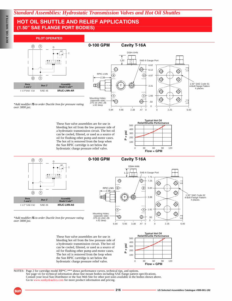
216 US Selected Assemblies Catalogue #999-901-192
Standard Assemblies: Hydrostatic Transmission Valves and Hot Oil Shuttles
HOT OIL SHUTTLE AND RELIEF APPLICATIONS(1.50” SAE FLANGE PORT BODIES)
PILOT OPERATED
0-100 GPM Cavity T-16A
Ports1 and 2 Port T Assembly
Model Code*
1 1/2”SAE C61 SAE-16 XRJC-LNN-AR
*Add modifier /S to order Ductile Iron for pressure rating over 3000 psi.
0-100 GPM Cavity T-16A
Ports1 and 2 Port T Assembly
Model Code*
1 1/2” SAE C62 SAE-16 XRJC-LNN-A6
*Add modifier /S to order Ductile Iron for pressure rating over 3000 psi.
NOTES: Page 2 for cartridge model RP*C-*** shows performance curves, technical tips, and options.See page vii for technical information about line mount bodies including SAE flange pattern specifications.Consult your local Sun Distributor or the Sun Web Site for other port sizes available in the bodies shown above.Go to www.sunhydraulics.com for more product information and pricing.
12 G
T
12
.472.385.94
DSIH-XHN
SAE-6 Gauge Port
2.38
4.56 0
0
RPIC-LNN
1.62
.50
1.66
3.31
4.97
6.12
6.62
0 2.25 6.00
1.50” SAE Code 614-Bolt Flange Pattern
4 places.T G
2 2
1 1Mounting Holes:(opposite side)
.375-16 UNC-2Bx.62 deep
Flow = GPM
P =
psi
500
200
30 60 90
400
120
300
100
0
Typical Hot OilRelief/Shuttle PerformanceThese Sun valve assemblies are for use in
bleeding hot oil from the low pressure side ofa hydrostatic transmission circuit. The hot oilcan be cooled, filtered, or used as a source of oil for flushing other pump and motor cases.The hot oil is removed from the loop whenthe Sun RPIC cartridge is set below thehydrostatic charge pressure relief valve.
12
G
T
12
Mounting Holes:(opposite side)
.375-16 UNC-2Bx.62 deep
RPIC-LNN
DSIH-XHN
1.50” SAE Code 624-Bolt Flange Pattern
4 places.
1
2 2
1
GT
2.38
1.12
6.94 .473.385.56 0 0
0.50
1.91
3.88
5.84
7.25
7.75
2.25 6.00
SAE-6 Gauge Port
Flow = GPM
P =
psi
500
200
30 60 90
400
120
300
100
0
Typical Hot OilRelief/Shuttle PerformanceThese Sun valve assemblies are for use in
bleeding hot oil from the low pressure side ofa hydrostatic transmission circuit. The hot oilcan be cooled, filtered, or used as a source of oil for flushing other pump and motor cases.The hot oil is removed from the loop whenthe Sun RPIC cartridge is set below thehydrostatic charge pressure relief valve.
HO
T O
IL S
HU
TT
LE
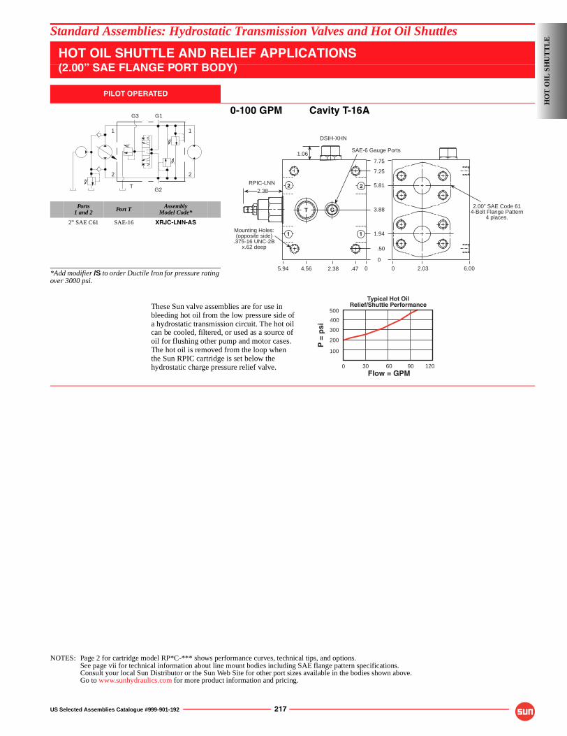
US Selected Assemblies Catalogue #999-901-192 217
Standard Assemblies: Hydrostatic Transmission Valves and Hot Oil Shuttles
HOT OIL SHUTTLE AND RELIEF APPLICATIONS(2.00” SAE FLANGE PORT BODY)
PILOT OPERATED
0-100 GPM Cavity T-16A
Ports1 and 2 Port T Assembly
Model Code*
2” SAE C61 SAE-16 XRJC-LNN-AS
*Add modifier /S to order Ductile Iron for pressure rating over 3000 psi.
NOTES: Page 2 for cartridge model RP*C-*** shows performance curves, technical tips, and options.See page vii for technical information about line mount bodies including SAE flange pattern specifications.Consult your local Sun Distributor or the Sun Web Site for other port sizes available in the bodies shown above.Go to www.sunhydraulics.com for more product information and pricing.
2
11
2
G2
G1G3
TRPIC-LNN
1.06SAE-6 Gauge Ports
.472.384.565.94 0
Mounting Holes:(opposite side)
.375-16 UNC-2Bx.62 deep
0
2.38
0 2.03 6.00
7.75
7.25
5.81
3.88
1.94
.50
DSIH-XHN
T G
11
2 2
2.00” SAE Code 614-Bolt Flange Pattern
4 places.
Flow = GPM
P =
psi
500
200
30 60 90
400
120
300
100
0
Typical Hot OilRelief/Shuttle PerformanceThese Sun valve assemblies are for use in
bleeding hot oil from the low pressure side ofa hydrostatic transmission circuit. The hot oilcan be cooled, filtered, or used as a source of oil for flushing other pump and motor cases.The hot oil is removed from the loop whenthe Sun RPIC cartridge is set below thehydrostatic charge pressure relief valve.
HO
T O
IL S
HU
TT
LE
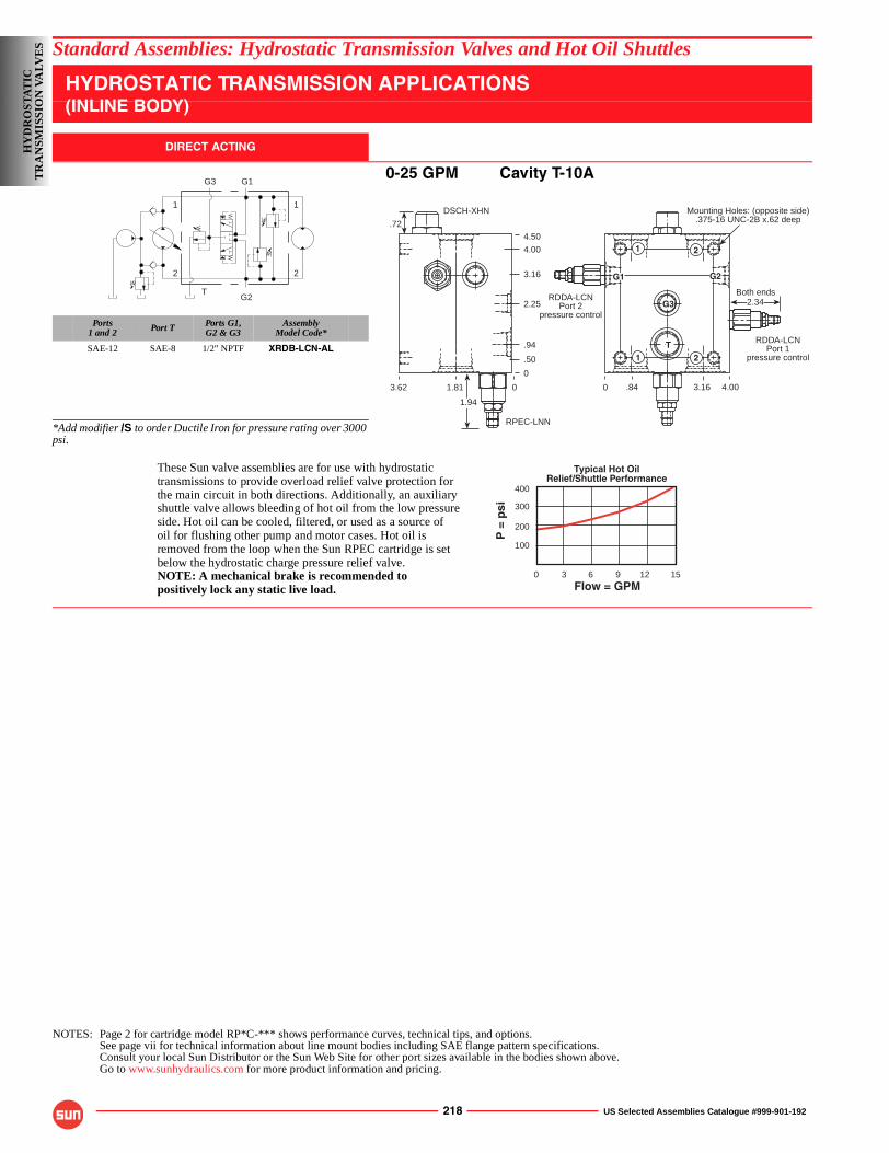
218 US Selected Assemblies Catalogue #999-901-192
Standard Assemblies: Hydrostatic Transmission Valves and Hot Oil Shuttles
HYDROSTATIC TRANSMISSION APPLICATIONS(INLINE BODY)
DIRECT ACTING
0-25 GPM Cavity T-10A
Ports1 and 2 Port T Ports G1,
G2 & G3Assembly
Model Code*
SAE-12 SAE-8 1/2” NPTF XRDB-LCN-AL
*Add modifier /S to order Ductile Iron for pressure rating over 3000 psi.
NOTES: Page 2 for cartridge model RP*C-*** shows performance curves, technical tips, and options.See page vii for technical information about line mount bodies including SAE flange pattern specifications.Consult your local Sun Distributor or the Sun Web Site for other port sizes available in the bodies shown above.Go to www.sunhydraulics.com for more product information and pricing.
2
11
2
G2
G1G3
T
1 2
DSCH-XHN
2.34
1.813.62
1
Mounting Holes: (opposite side).375-16 UNC-2B x.62 deep
RPEC-LNN
2
G3
T
G1 G2
RDDA-LCNPort 2
pressure control
RDDA-LCNPort 1
pressure control
.72
1.94
Both ends
0
0
.94
2.25
3.16
4.00
4.50
.50
0 .84 3.16 4.00
Flow = GPM
400
3 6 9 12
300
100
200
150
Typical Hot OilRelief/Shuttle Performance
P =
psi
These Sun valve assemblies are for use with hydrostatictransmissions to provide overload relief valve protection forthe main circuit in both directions. Additionally, an auxiliaryshuttle valve allows bleeding of hot oil from the low pressureside. Hot oil can be cooled, filtered, or used as a source ofoil for flushing other pump and motor cases. Hot oil isremoved from the loop when the Sun RPEC cartridge is setbelow the hydrostatic charge pressure relief valve.NOTE: A mechanical brake is recommended topositively lock any static live load.
HY
DR
OST
AT
ICT
RA
NSM
ISSI
ON
VA
LVE
S
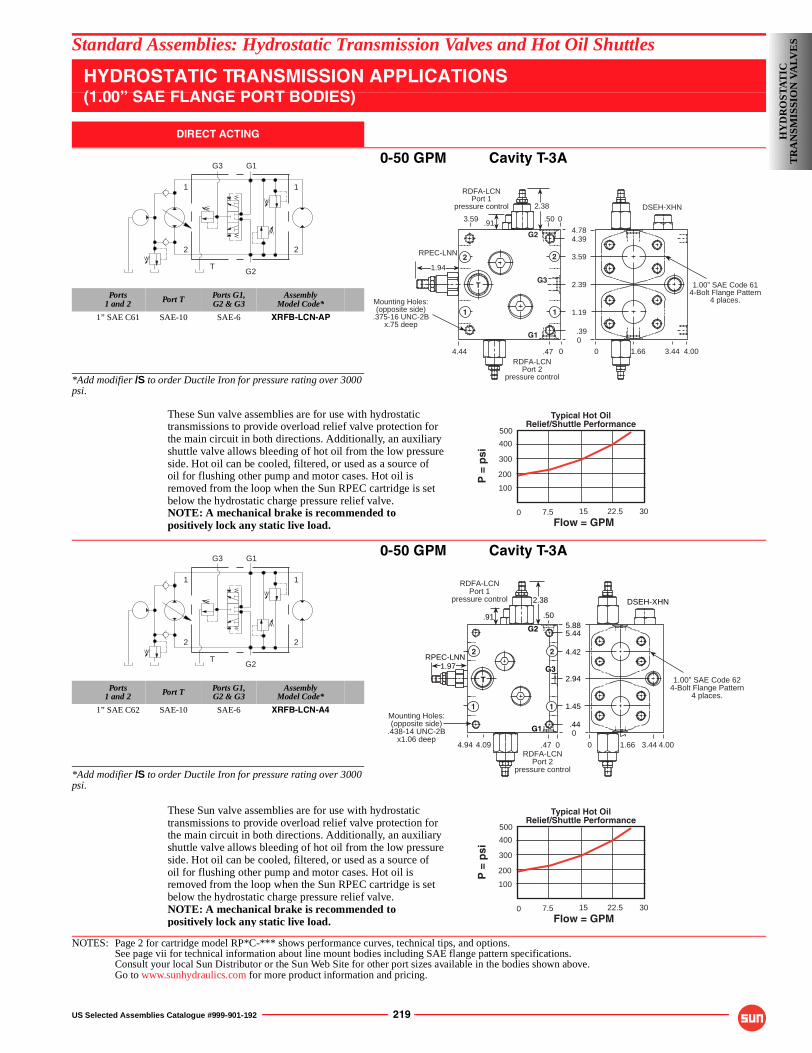
US Selected Assemblies Catalogue #999-901-192 219
Standard Assemblies: Hydrostatic Transmission Valves and Hot Oil Shuttles
HYDROSTATIC TRANSMISSION APPLICATIONS(1.00” SAE FLANGE PORT BODIES)
DIRECT ACTING
0-50 GPM Cavity T-3A
Ports1 and 2 Port T Ports G1,
G2 & G3Assembly
Model Code*
1” SAE C61 SAE-10 SAE-6 XRFB-LCN-AP
*Add modifier /S to order Ductile Iron for pressure rating over 3000 psi.
0-50 GPM Cavity T-3A
Ports1 and 2 Port T Ports G1,
G2 & G3Assembly
Model Code*
1” SAE C62 SAE-10 SAE-6 XRFB-LCN-A4
*Add modifier /S to order Ductile Iron for pressure rating over 3000 psi.
NOTES: Page 2 for cartridge model RP*C-*** shows performance curves, technical tips, and options.See page vii for technical information about line mount bodies including SAE flange pattern specifications.Consult your local Sun Distributor or the Sun Web Site for other port sizes available in the bodies shown above.Go to www.sunhydraulics.com for more product information and pricing.
2
11
2
G2
G1G3
T
RPEC-LNN
2.38
Mounting Holes:(opposite side)
.375-16 UNC-2Bx.75 deep
1.94
0
0.474.44RDFA-LCN
Port 2pressure control
RDFA-LCNPort 1
pressure control
3.59 .91 .50 0
4.78
3.59
2.39
1.19
.39
4.39
0 1.66 3.44 4.00
DSEH-XHN
1
2
T
2
1
G1
G2
G31.00” SAE Code 61
4-Bolt Flange Pattern4 places.
Flow = GPM
P =
psi
500
200
7.5 15 22.5
400
30
300
100
0
Typical Hot OilRelief/Shuttle Performance
These Sun valve assemblies are for use with hydrostatictransmissions to provide overload relief valve protection forthe main circuit in both directions. Additionally, an auxiliaryshuttle valve allows bleeding of hot oil from the low pressureside. Hot oil can be cooled, filtered, or used as a source ofoil for flushing other pump and motor cases. Hot oil isremoved from the loop when the Sun RPEC cartridge is setbelow the hydrostatic charge pressure relief valve.NOTE: A mechanical brake is recommended topositively lock any static live load.
2
11
2
G2
G1G3
T
1.00” SAE Code 624-Bolt Flange Pattern
4 places.
Mounting Holes:(opposite side)
.438-14 UNC-2Bx1.06 deep
.44
1.45
2.94
4.42
5.445.88
.50.91
DSEH-XHN
RPEC-LNN
T
1.97
1
2
RDFA-LCNPort 2
pressure control
RDFA-LCNPort 1
pressure control
1
2
G3
G2
G1
2.38
0.474.94 4.09 0 1.66 3.44 4.00
0
Flow = GPM
P =
psi
500
200
7.5 15 22.5
400
30
300
100
0
Typical Hot OilRelief/Shuttle Performance
These Sun valve assemblies are for use with hydrostatictransmissions to provide overload relief valve protection forthe main circuit in both directions. Additionally, an auxiliaryshuttle valve allows bleeding of hot oil from the low pressureside. Hot oil can be cooled, filtered, or used as a source ofoil for flushing other pump and motor cases. Hot oil isremoved from the loop when the Sun RPEC cartridge is setbelow the hydrostatic charge pressure relief valve.NOTE: A mechanical brake is recommended topositively lock any static live load.
HY
DR
OST
AT
ICT
RA
NSM
ISSI
ON
VA
LVE
S
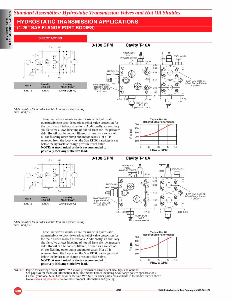
220 US Selected Assemblies Catalogue #999-901-192
Standard Assemblies: Hydrostatic Transmission Valves and Hot Oil Shuttles
HYDROSTATIC TRANSMISSION APPLICATIONS(1.25” SAE FLANGE PORT BODIES)
DIRECT ACTING
0-100 GPM Cavity T-16A
Port T Ports G1,G2 & G3
AssemblyModel Code*
SAE-12 SAE-6 XRHB-LCN-AQ
*Add modifier /S to order Ductile Iron for pressure rating over 3000 psi.
0-100 GPM Cavity T-16A
Port T Ports G1,G2 & G3
AssemblyModel Code*
SAE-12 SAE-6 XRHB-LCN-A5
*Add modifier /S to order Ductile Iron for pressure rating over 3000 psi.
NOTES: Page 2 for cartridge model RP*C-*** shows performance curves, technical tips, and options.See page vii for technical information about line mount bodies including SAE flange pattern specifications.Consult your local Sun Distributor or the Sun Web Site for other port sizes available in the bodies shown above.Go to www.sunhydraulics.com for more product information and pricing.
2
11
2
G2
G1G3
T
RPGC-LNN
.94
Mounting Holes:(opposite side)
.375-16 UNC-2B x.75 deep
0
4.94 0.473.94
2.09
6.38
5.81
4.81
3.19
1.56
.56
2
1
T
G1
G3
G2
3.00DSGH-XHN
04.38
5.00
RDHA-LCNPort 2
pressure control
RDHA-LCNPort 1
pressure control
0.44
1
2
1.25” SAE Code 614-Bolt Flange Pattern
4 places.
Flow = GPM
P =
psi
500
200
15 30 45
400
60
300
100
0
Typical Hot OilRelief/Shuttle Performance
These Sun valve assemblies are for use with hydrostatictransmissions to provide overload relief valve protection forthe main circuit in both directions. Additionally, an auxiliaryshuttle valve allows bleeding of hot oil from the low pressureside. Hot oil can be cooled, filtered, or used as a source ofoil for flushing other pump and motor cases. Hot oil isremoved from the loop when the Sun RPGC cartridge is setbelow the hydrostatic charge pressure relief valve.NOTE: A mechanical brake is recommended topositively lock any static live load.
2
11
2
G2
G1G3
T
RPGC-LNN
3.00
Mounting Holes:(opposite side)
.375-16 UNC-2B x.75 deep
2.09
0
4.94 0.473.94
.94
RDHA-LCNPort 2
pressure control
RDHA-LCNPort 1
pressure control
6.385.81
4.81
3.19
1.56
.56
0.44
DSGH-XHN
0 4.38 5.00
1
2 2
1
T
G1
G3
G2
1.25” SAE Code 624-Bolt Flange Pattern
4 places.
Flow = GPM
P =
psi
500
200
15 30 45
400
60
300
100
0
Typical Hot OilRelief/Shuttle Performance
These Sun valve assemblies are for use with hydrostatictransmissions to provide overload relief valve protection forthe main circuit in both directions. Additionally, an auxiliaryshuttle valve allows bleeding of hot oil from the low pressureside. Hot oil can be cooled, filtered, or used as a source ofoil for flushing other pump and motor cases. Hot oil isremoved from the loop when the Sun RPGC cartridge is setbelow the hydrostatic charge pressure relief valve.NOTE: A mechanical brake is recommended topositively lock any static live load.
HY
DR
OST
AT
ICT
RA
NSM
ISSI
ON
VA
LVE
S
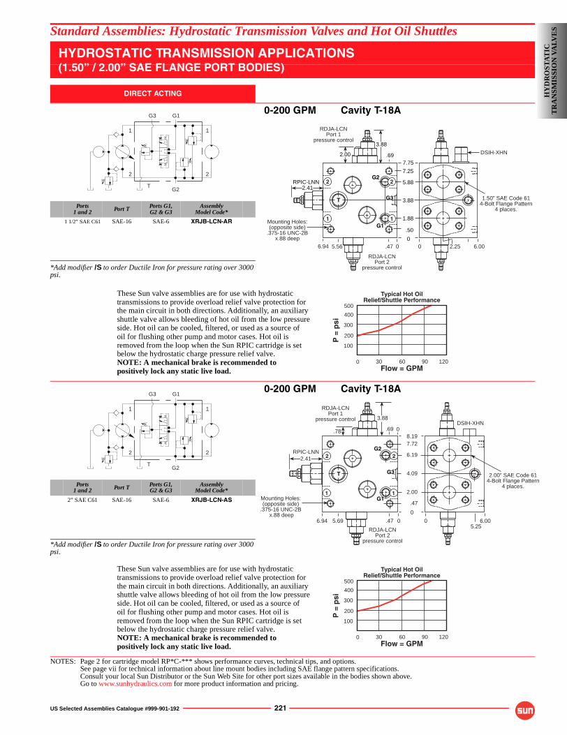
US Selected Assemblies Catalogue #999-901-192 221
Standard Assemblies: Hydrostatic Transmission Valves and Hot Oil Shuttles
HYDROSTATIC TRANSMISSION APPLICATIONS(1.50” / 2.00” SAE FLANGE PORT BODIES)
DIRECT ACTING
0-200 GPM Cavity T-18A
Ports1 and 2 Port T Ports G1,
G2 & G3Assembly
Model Code*
1 1/2” SAE C61 SAE-16 SAE-6 XRJB-LCN-AR
*Add modifier /S to order Ductile Iron for pressure rating over 3000 psi.
0-200 GPM Cavity T-18A
Ports1 and 2 Port T Ports G1,
G2 & G3Assembly
Model Code*
2” SAE C61 SAE-16 SAE-6 XRJB-LCN-AS
*Add modifier /S to order Ductile Iron for pressure rating over 3000 psi.
NOTES: Page 2 for cartridge model RP*C-*** shows performance curves, technical tips, and options.See page vii for technical information about line mount bodies including SAE flange pattern specifications.Consult your local Sun Distributor or the Sun Web Site for other port sizes available in the bodies shown above.Go to www.sunhydraulics.com for more product information and pricing.
2
11
2
G2
G1G3
T
Mounting Holes:(opposite side)
.375-16 UNC-2Bx.88 deep
RDJA-LCNPort 2
pressure control
1.50” SAE Code 614-Bolt Flange Pattern
4 places.
3.88
7.75
5.88
1.88
7.25
.50
RPIC-LNN
0
G1
G2
T G3
RDJA-LCNPort 1
pressure control
2 2
1 1
2.41
2.00
3.88
DSIH-XHN
0.476.94 5.56 0 2.25 6.00
.69
Flow = GPM
P =
psi
500
200
30 60 90
400
120
300
100
0
Typical Hot OilRelief/Shuttle Performance
These Sun valve assemblies are for use with hydrostatictransmissions to provide overload relief valve protection forthe main circuit in both directions. Additionally, an auxiliaryshuttle valve allows bleeding of hot oil from the low pressureside. Hot oil can be cooled, filtered, or used as a source ofoil for flushing other pump and motor cases. Hot oil isremoved from the loop when the Sun RPIC cartridge is setbelow the hydrostatic charge pressure relief valve.NOTE: A mechanical brake is recommended topositively lock any static live load.
2
11
2
G2
G1G3
T
DSIH-XHN3.88
Mounting Holes:(opposite side)
.375-16 UNC-2B x.88 deep 0
6.94 0.475.69
RDJA-LCNPort 2
pressure control
.78
RDJA-LCNPort 1
pressure control
RPIC-LNN2.41
05.25
6.00
8.197.72
6.19
4.09
2.00
.47
0.69
G1
G2
G3T
2
1 1
2
2.00” SAE Code 614-Bolt Flange Pattern
4 places.
Flow = GPM
P =
psi
500
200
30 60 90
400
120
300
100
0
Typical Hot OilRelief/Shuttle Performance
These Sun valve assemblies are for use with hydrostatictransmissions to provide overload relief valve protection forthe main circuit in both directions. Additionally, an auxiliaryshuttle valve allows bleeding of hot oil from the low pressureside. Hot oil can be cooled, filtered, or used as a source ofoil for flushing other pump and motor cases. Hot oil isremoved from the loop when the Sun RPIC cartridge is setbelow the hydrostatic charge pressure relief valve.NOTE: A mechanical brake is recommended topositively lock any static live load.
HY
DR
OST
AT
ICT
RA
NSM
ISSI
ON
VA
LVE
S
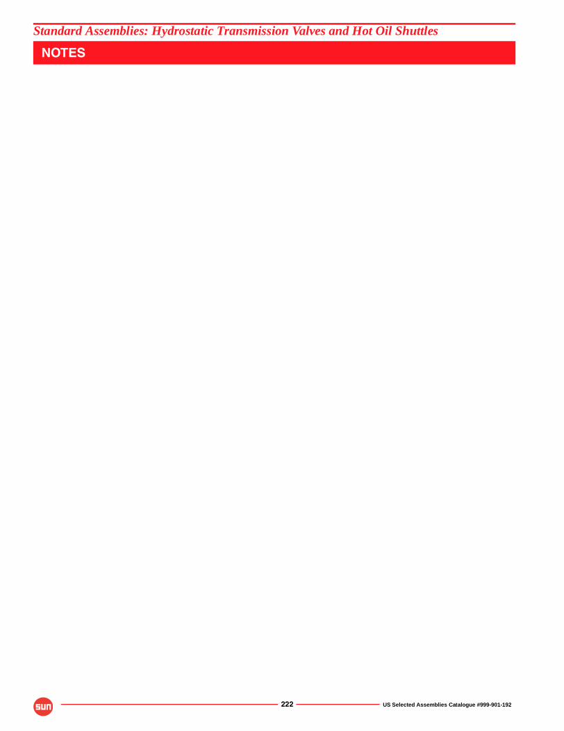
222 US Selected Assemblies Catalogue #999-901-192
Standard Assemblies: Hydrostatic Transmission Valves and Hot Oil Shuttles
NOTES
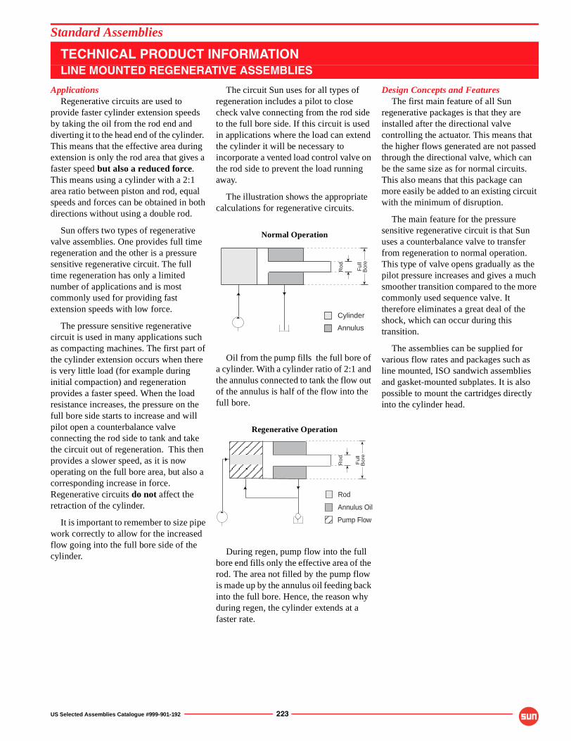
US Selected Assemblies Catalogue #999-901-192 223
ApplicationsRegenerative circuits are used to
provide faster cylinder extension speeds by taking the oil from the rod end and diverting it to the head end of the cylinder. This means that the effective area during extension is only the rod area that gives a faster speed but also a reduced force. This means using a cylinder with a 2:1 area ratio between piston and rod, equal speeds and forces can be obtained in both directions without using a double rod.
Sun offers two types of regenerative valve assemblies. One provides full time regeneration and the other is a pressure sensitive regenerative circuit. The full time regeneration has only a limited number of applications and is most commonly used for providing fast extension speeds with low force.
The pressure sensitive regenerative circuit is used in many applications such as compacting machines. The first part of the cylinder extension occurs when there is very little load (for example during initial compaction) and regeneration provides a faster speed. When the load resistance increases, the pressure on the full bore side starts to increase and will pilot open a counterbalance valve connecting the rod side to tank and take the circuit out of regeneration. This then provides a slower speed, as it is now operating on the full bore area, but also a corresponding increase in force. Regenerative circuits do not affect the retraction of the cylinder.
It is important to remember to size pipe work correctly to allow for the increased flow going into the full bore side of the cylinder.
The circuit Sun uses for all types of regeneration includes a pilot to close check valve connecting from the rod side to the full bore side. If this circuit is used in applications where the load can extend the cylinder it will be necessary to incorporate a vented load control valve on the rod side to prevent the load running away.
The illustration shows the appropriate calculations for regenerative circuits.
Normal Operation
Oil from the pump fills the full bore of a cylinder. With a cylinder ratio of 2:1 and the annulus connected to tank the flow out of the annulus is half of the flow into the full bore.
Regenerative Operation
During regen, pump flow into the full bore end fills only the effective area of the rod. The area not filled by the pump flow is made up by the annulus oil feeding back into the full bore. Hence, the reason why during regen, the cylinder extends at a faster rate.
Design Concepts and FeaturesThe first main feature of all Sun
regenerative packages is that they are installed after the directional valve controlling the actuator. This means that the higher flows generated are not passed through the directional valve, which can be the same size as for normal circuits. This also means that this package can more easily be added to an existing circuit with the minimum of disruption.
The main feature for the pressure sensitive regenerative circuit is that Sun uses a counterbalance valve to transfer from regeneration to normal operation. This type of valve opens gradually as the pilot pressure increases and gives a much smoother transition compared to the more commonly used sequence valve. It therefore eliminates a great deal of the shock, which can occur during this transition.
The assemblies can be supplied for various flow rates and packages such as line mounted, ISO sandwich assemblies and gasket-mounted subplates. It is also possible to mount the cartridges directly into the cylinder head.
Rod Ful
lB
ore
Cylinder
Annulus
Ro
d
Fu
llB
ore
Rod
Annulus Oil
Pump Flow
Standard Assemblies
TECHNICAL PRODUCT INFORMATIONLINE MOUNTED REGENERATIVE ASSEMBLIES
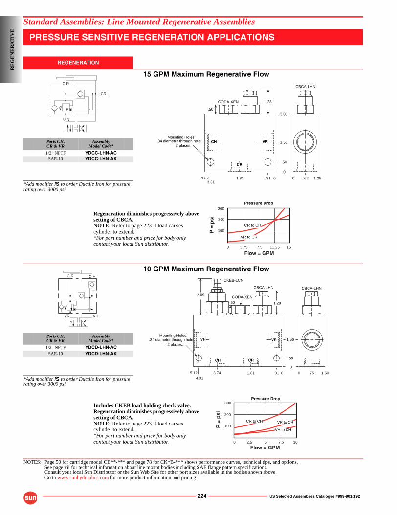
224 US Selected Assemblies Catalogue #999-901-192
Standard Assemblies: Line Mounted Regenerative Assemblies
PRESSURE SENSITIVE REGENERATION APPLICATIONS
REGENERATION
15 GPM Maximum Regenerative Flow
Ports CH,CR & VR
AssemblyModel Code*
1/2” NPTF YDCC-LHN-ACSAE-10 YDCC-LHN-AK
*Add modifier /S to order Ductile Iron for pressure rating over 3000 psi.
10 GPM Maximum Regenerative Flow
Ports CH,CR & VR
AssemblyModel Code*
1/2” NPTF YDCD-LHN-ACSAE-10 YDCD-LHN-AK
*Add modifier /S to order Ductile Iron for pressure rating over 3000 psi.
NOTES: Page 50 for cartridge model CB**-*** and page 78 for CK*B-*** shows performance curves, technical tips, and options.See page vii for technical information about line mount bodies including SAE flange pattern specifications.Consult your local Sun Distributor or the Sun Web Site for other port sizes available in the bodies shown above.Go to www.sunhydraulics.com for more product information and pricing.
C R
CR
V R
1.81
0
1.28
.50
.50
1.56
3.00
3.31
CODA-XEN
CBCA-LHN
Mounting Holes:.34 diameter through hole
2 places.CH VR
CR
3.62 .31 00 .62 1.25
Regeneration diminishes progressively above
NOTE: Refer to page 223 if load causescylinder to extend.*For part number and price for body onlycontact your local Sun distributor.
setting of CBCA.
0
Flow = GPM
P =
psi
300
3.75 7.5 11.25 15
200
100CR to CH
VR to CR
Pressure Drop
C R
VR
C H
VH
CODA-XEN.50
2.09
0
.50
1.56
CBCA-LHN
1.28
CBCA-LHN
CKEB-LCN
VH VR
CH CR
.34 diameter through hole
1.81 .313.745.124.81
0 0 .75 1.50
Mounting Holes:
2 places.
Regeneration diminishes progressively above
NOTE: Refer to page 223 if load causescylinder to extend.*For part number and price for body onlycontact your local Sun distributor.
setting of CBCA.
Includes CKEB load holding check valve.
CR to CH
0
Flow = GPM
P =
psi
300
2.5 5 7.5 10
200
100
Pressure Drop
VR to CR
VH to CH
RE
GE
NE
RA
TIV
E
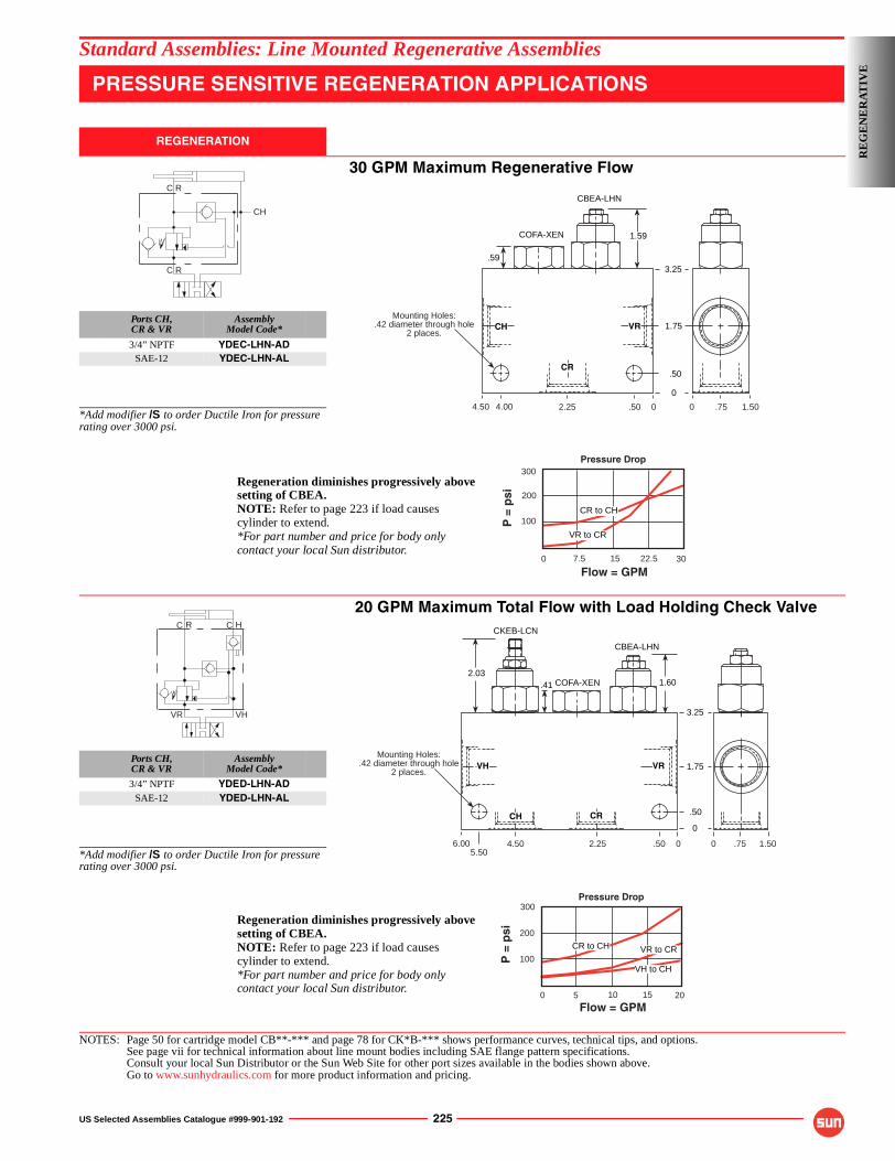
US Selected Assemblies Catalogue #999-901-192 225
Standard Assemblies: Line Mounted Regenerative Assemblies
PRESSURE SENSITIVE REGENERATION APPLICATIONS
REGENERATION
30 GPM Maximum Regenerative Flow
Ports CH,CR & VR
AssemblyModel Code*
3/4” NPTF YDEC-LHN-ADSAE-12 YDEC-LHN-AL
*Add modifier /S to order Ductile Iron for pressure rating over 3000 psi.
20 GPM Maximum Total Flow with Load Holding Check Valve
Ports CH,CR & VR
AssemblyModel Code*
3/4” NPTF YDED-LHN-ADSAE-12 YDED-LHN-AL
*Add modifier /S to order Ductile Iron for pressure rating over 3000 psi.
NOTES: Page 50 for cartridge model CB**-*** and page 78 for CK*B-*** shows performance curves, technical tips, and options.See page vii for technical information about line mount bodies including SAE flange pattern specifications.Consult your local Sun Distributor or the Sun Web Site for other port sizes available in the bodies shown above.Go to www.sunhydraulics.com for more product information and pricing.
C R
C R
CH
0
CH VR
.50
1.75
3.25
CBEA-LHN
COFA-XEN
CR
.59
Mounting Holes:.42 diameter through hole
2 places.
1.59
.502.254.50 4.00 0 0 .75 1.50
0
Flow = GPM
P =
psi
300
7.5 15 22.5 30
200
100CR to CH
VR to CR
Pressure Drop
Regeneration diminishes progressively above
NOTE: Refer to page 223 if load causescylinder to extend.*For part number and price for body onlycontact your local Sun distributor.
setting of CBEA.
C R C H
VR VH 3.25
CBEA-LHN
1.60.412.03
COFA-XEN
CKEB-LCN
2.254.505.50
6.00 .50 0
VH VR
0 .75 1.50
1.75
.50
0CH CR
Mounting Holes:.42 diameter through hole
2 places.
CR to CH
0
Flow = GPM
P =
psi
300
5 10 15 20
200
100
Pressure Drop
VR to CR
VH to CH
Regeneration diminishes progressively above
NOTE: Refer to page 223 if load causescylinder to extend.*For part number and price for body onlycontact your local Sun distributor.
setting of CBEA.
RE
GE
NE
RA
TIV
E
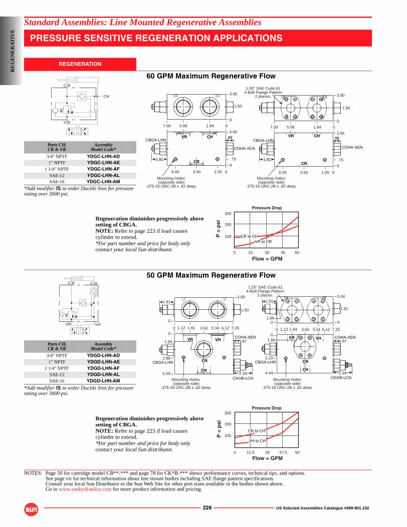
226 US Selected Assemblies Catalogue #999-901-192
Standard Assemblies: Line Mounted Regenerative Assemblies
PRESSURE SENSITIVE REGENERATION APPLICATIONS
REGENERATION
60 GPM Maximum Regenerative Flow
Ports CH,CR & VR
AssemblyModel Code*
3/4” NPTF YDGC-LHN-AD1” NPTF YDGC-LHN-AE
1 1/4” NPTF YDGC-LHN-AFSAE-12 YDGC-LHN-ALSAE-16 YDGC-LHN-AM
*Add modifier /S to order Ductile Iron for pressure rating over 3000 psi.
50 GPM Maximum Regenerative Flow
Ports CH,CR & VR
AssemblyModel Code*
3/4” NPTF YDGD-LHN-AD1” NPTF YDGD-LHN-AE
1 1/4” NPTF YDGD-LHN-AFSAE-12 YDGD-LHN-ALSAE-16 YDGD-LHN-AM
*Add modifier /S to order Ductile Iron for pressure rating over 3000 psi.
NOTES: Page 50 for cartridge model CB**-*** and page 78 for CK*B-*** shows performance curves, technical tips, and options.See page vii for technical information about line mount bodies including SAE flange pattern specifications.Consult your local Sun Distributor or the Sun Web Site for other port sizes available in the bodies shown above.Go to www.sunhydraulics.com for more product information and pricing.
C R
V R
CH
.88
COHA-XEN
CBGA-LHN
COHA-XEN
CBGA-LHN
7.00 01.945.06
CH VR
1.50
0
4.00
3.00
03.506.00 1.00
1.81
0
.75CR
CHVR
1.81
.88
03.506.00 1.00
0
.75CR
7.00 01.945.06
0
3.94
1.50
3.00
Mounting Holes:(opposite side)
.375-16 UNC-2B x .62 deep.
Mounting Holes:(opposite side)
.375-16 UNC-2B x .62 deep.
1.00” SAE Code 614-Bolt Flange Pattern
2 places.
0
Flow = GPM
P =
psi
300
15 30 45 60
200
100 CR to CH
Pressure Drop
VR to CR
Regeneration diminishes progressively above
NOTE: Refer to page 223 if load causescylinder to extend.*For part number and price for body onlycontact your local Sun distributor.
setting of CBGA.
C R C H
VR VH
CBGA-LHN
COHA-XEN COHA-XEN
CBGA-LHN
CKGB-LCN CKGB-LCN
VR VH
CH
0
3.00
7.255.341.91
1.81
0
01.12 3.62 6.12
1.50
3.441.81
0 7.255.311.94
0
01.12 3.62 6.12
1.81
1.690
.871.56
2.22
2.344.44CH
VHVR
5.00
.87
2.34
1.94
2.88CRCR
1.25” SAE Code 614-Bolt Flange Pattern
2 places.
Mounting Holes:(opposite side)
.375-16 UNC-2B x .62 deep.
Mounting Holes:(opposite side)
.375-16 UNC-2B x .62 deep.
0
Flow = GPM
P =
psi
300
12.5 25 37.5 50
200
100CR to CH
Pressure Drop
VH to CH
Regeneration diminishes progressively above
NOTE: Refer to page 223 if load causescylinder to extend.*For part number and price for body onlycontact your local Sun distributor.
setting of CBGA.
RE
GE
NE
RA
TIV
E
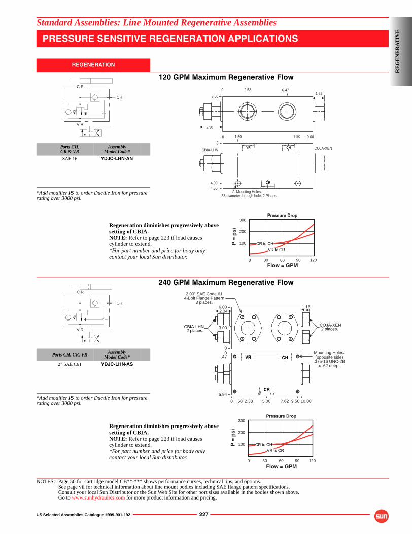
US Selected Assemblies Catalogue #999-901-192 227
Standard Assemblies: Line Mounted Regenerative Assemblies
PRESSURE SENSITIVE REGENERATION APPLICATIONS
REGENERATION
120 GPM Maximum Regenerative Flow
Ports CH,CR & VR
AssemblyModel Code*
SAE 16 YDJC-LHN-AN
*Add modifier /S to order Ductile Iron for pressure rating over 3000 psi.
240 GPM Maximum Regenerative Flow
Ports CH, CR, VR AssemblyModel Code*
2” SAE C61 YDJC-LHN-AS
*Add modifier /S to order Ductile Iron for pressure rating over 3000 psi.
NOTES: Page 50 for cartridge model CB**-*** shows performance curves, technical tips, and options.See page vii for technical information about line mount bodies including SAE flange pattern specifications.Consult your local Sun Distributor or the Sun Web Site for other port sizes available in the bodies shown above.Go to www.sunhydraulics.com for more product information and pricing.
C R
CH
V R
VR CH
CR
00
COJA-XENCBIA-LHN
1.50 7.50 9.00
4.004.50
Mounting Holes:.53 diameter through hole. 2 Places.
0
3.50
2.53 6.471.22
2.38
0Flow = GPM
P =
psi
300
30 60 90 120
200
100 CR to CH
Pressure Drop
VR to CR
Regeneration diminishes progressively above
NOTE: Refer to page 223 if load causescylinder to extend.*For part number and price for body onlycontact your local Sun distributor.
setting of CBIA.
C R
CH
V R
0
6.00
CBIA-LHN2 places.
COJA-XEN2 places.
CR
VR CH
2.34
3.00
0.47
5.94
0 5.00
1.16
Mounting Holes:(opposite side)
.375-16 UNC-2Bx .62 deep.
.50 2.38 7.62 9.50 10.00
2.00” SAE Code 614-Bolt Flange Pattern
3 places.
0Flow = GPM
P =
psi
300
30 60 90 120
200
100 CR to CH
Pressure Drop
VR to CR
Regeneration diminishes progressively above
NOTE: Refer to page 223 if load causescylinder to extend.*For part number and price for body onlycontact your local Sun distributor.
setting of CBIA.
RE
GE
NE
RA
TIV
E
228 US Selected Assemblies Catalogue #999-901-192
Standard Assemblies: Line Mounted Regenerative Assemblies
NOTES
RE
GE
NE
RA
TIV
E
US Selected Assemblies Catalogue #999-901-192 229
Applications
Applications
The gerotor type gear motor is used on a large number of mobile and industrial applications. It is often necessary to incorporate valves in the circuit with the motor to control the flow and pressure. It may also be necessary to incorporate load control valves in the circuit.
It is possible to mount line mounted valves into the pipework feeding the motor, but Sun offers a large range of valves that can be bolted directly onto the motor interface. This eliminates pipework and provides the control directly at the motor.
The use of Sun cartridge valves in these assemblies means that in the event of a problem, it is a simple task to replace the cartridge rather than have to replace the complete valve.
On the smaller size motors the same gasket mounted face is used by at least four different manufacturers of this type of motor. The list below provides a quick cross-reference.
Manufacturer (general motor type with gasket mounted interface)
Eaton (S Type)White (RS 06 and RS 46)Parker/Ross/Nichols/Prince (TA, TB, TD, NE, 110A, 130S, 400S)
On the specification in this catalogue for the smaller size of motor, we are using the Eaton reference number type as they are probably the largest manufacturer.
For the larger size of motors we are only showing the Eaton reference of 2000 series and 4000 series.
Design Concepts and Features
The valve assemblies shown for all sizes of motor are counterbalance valves and cross line relief valves. The counterbalance valves provide load holding and load control while the cross line relief valves provide over pressure protection. The Sun counterbalance valves provide excellent control with low hysteresis and minimum leakage. The relief valves are fast acting with minimum overshoot for excellent protection.
On the smaller sizes of motor, Sun also offers flow control, which can accurately control the motor speed. The type of valve offered is a pressure compensated flow control valve but for more basic flow control a simple restrictor valve can also be used. Sun also has a further expanded range of bolt on valve assemblies. Consult the Sun factory or your local distributor for further information.
DIR
EC
T M
OT
OR
MO
UN
TStandard Assemblies
TECHNICAL PRODUCT INFORMATIONDIRECT MOTOR MOUNTED ASSEMBLIESChar-Lynn S Series
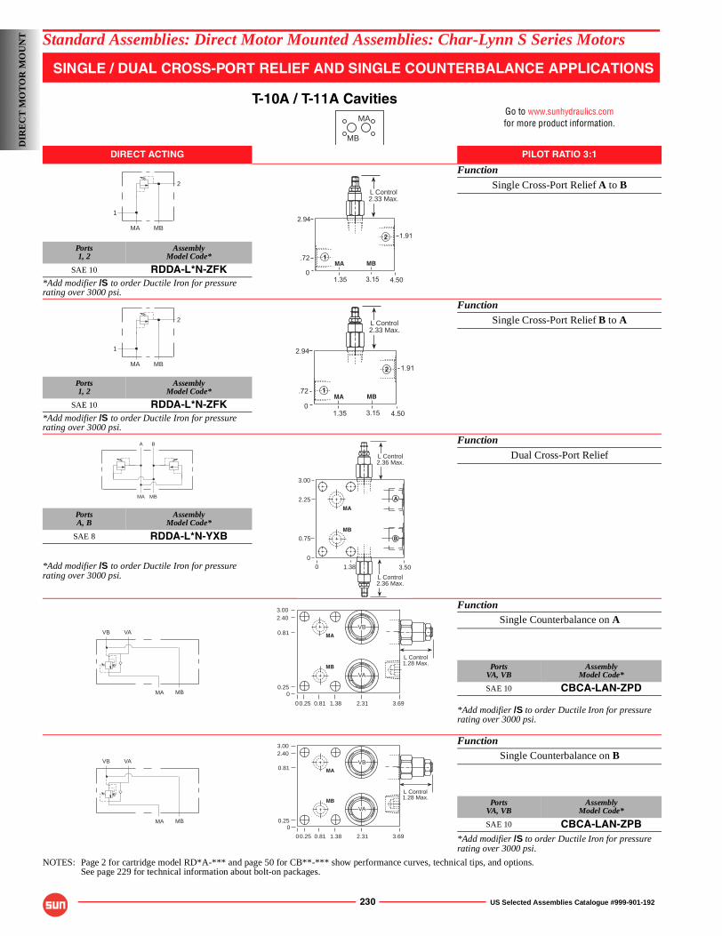
230 US Selected Assemblies Catalogue #999-901-192
Standard Assemblies: Direct Motor Mounted Assemblies: Char-Lynn S Series Motors
SINGLE / DUAL CROSS-PORT RELIEF AND SINGLE COUNTERBALANCE APPLICATIONS
T-10A / T-11A CavitiesGo to www.sunhydraulics.comfor more product information.
DIRECT ACTING PILOT RATIO 3:1
Function
Single Cross-Port Relief A to B
Ports1, 2
AssemblyModel Code*
SAE 10 RDDA-L*N-ZFK*Add modifier /S to order Ductile Iron for pressure rating over 3000 psi.
Function
Single Cross-Port Relief B to A
Ports1, 2
AssemblyModel Code*
SAE 10 RDDA-L*N-ZFK*Add modifier /S to order Ductile Iron for pressure rating over 3000 psi.
Function
Dual Cross-Port Relief
PortsA, B
AssemblyModel Code*
SAE 8 RDDA-L*N-YXB
*Add modifier /S to order Ductile Iron for pressure rating over 3000 psi.
FunctionSingle Counterbalance on A
PortsVA, VB
AssemblyModel Code*
SAE 10 CBCA-LAN-ZPD
*Add modifier /S to order Ductile Iron for pressure rating over 3000 psi.
FunctionSingle Counterbalance on B
PortsVA, VB
AssemblyModel Code*
SAE 10 CBCA-LAN-ZPB*Add modifier /S to order Ductile Iron for pressure rating over 3000 psi.
NOTES: Page 2 for cartridge model RD*A-*** and page 50 for CB**-*** show performance curves, technical tips, and options.See page 229 for technical information about bolt-on packages.
MA
MB
1
MA MB
2
2.94
04.50
1.91
.72
1.35 3.15
2
1
L Control2.33 Max.
MA MB
1
MA MB
2
2.94
04.50
1.91
.72
1.35 3.15
2
1
L Control2.33 Max.
MA MB
A B
MA MB
3.501.3800
3.00
2.25
0.75
L Control2.36 Max.
L Control2.36 Max.
A
B
MA
MB
MA MB
VAVB
L Control1.28 Max.
3.002.40
0.81
0.250
2.311.380.810.250 3.69
VA
VBMA
MB
MA MB
VAVB
L Control1.28 Max.
3.002.40
0.81
0.250
2.311.380.810.250 3.69
VA
VBMA
MB
DIR
EC
T M
OT
OR
MO
UN
T
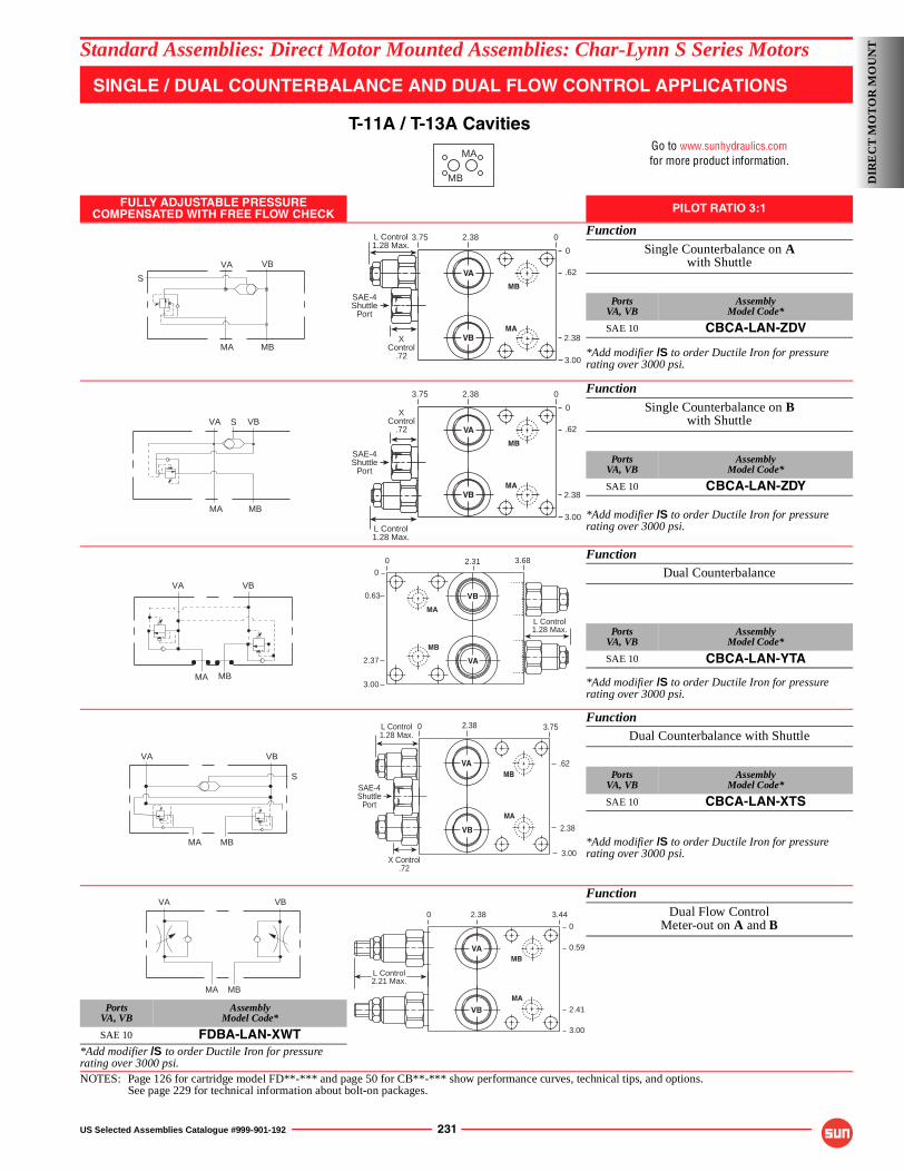
US Selected Assemblies Catalogue #999-901-192 231
Standard Assemblies: Direct Motor Mounted Assemblies: Char-Lynn S Series Motors
SINGLE / DUAL COUNTERBALANCE AND DUAL FLOW CONTROL APPLICATIONS
T-11A / T-13A CavitiesGo to www.sunhydraulics.comfor more product information.
FULLY ADJUSTABLE PRESSURECOMPENSATED WITH FREE FLOW CHECK PILOT RATIO 3:1
Function
Single Counterbalance on Awith Shuttle
PortsVA, VB
AssemblyModel Code*
SAE 10 CBCA-LAN-ZDV
*Add modifier /S to order Ductile Iron for pressure rating over 3000 psi.
Function
Single Counterbalance on Bwith Shuttle
PortsVA, VB
AssemblyModel Code*
SAE 10 CBCA-LAN-ZDY
*Add modifier /S to order Ductile Iron for pressure rating over 3000 psi.
FunctionDual Counterbalance
PortsVA, VB
AssemblyModel Code*
SAE 10 CBCA-LAN-YTA
*Add modifier /S to order Ductile Iron for pressure rating over 3000 psi.
FunctionDual Counterbalance with Shuttle
PortsVA, VB
AssemblyModel Code*
SAE 10 CBCA-LAN-XTS
*Add modifier /S to order Ductile Iron for pressure rating over 3000 psi.
FunctionDual Flow Control
Meter-out on A and B
PortsVA, VB
AssemblyModel Code*
SAE 10 FDBA-LAN-XWT*Add modifier /S to order Ductile Iron for pressure rating over 3000 psi.NOTES: Page 126 for cartridge model FD**-*** and page 50 for CB**-*** show performance curves, technical tips, and options.
See page 229 for technical information about bolt-on packages.
MA
MB
VA VB
MA MB
S.62
3.75
0
2.38
2.38 0
XControl
.72 3.00
L Control1.28 Max.
SAE-4Shuttle
Port
MA
MB
VB
VA
MA MB
VA VBS.62
3.75
0
2.38
2.38 0
XControl
.72
3.00L Control1.28 Max.
SAE-4Shuttle
Port
MA
MB
VB
VA
MBMA
VA VB
0
0
3.682.31
3.00
2.37
0.63
L Control1.28 Max.
VA
VB
MA
MB
VA
MA MB
S
VB
3.75
.62
2.38
2.380
3.00X Control
.72
L Control1.28 Max.
VA
VB
MA
MB
SAE-4Shuttle
Port
MA MB
VA VB
2.41
0
3.00
0.59
2.38 3.44
0
L Control2.21 Max.
VB
VA
MA
MB
DIR
EC
T M
OT
OR
MO
UN
T
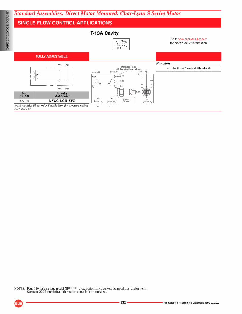
232 US Selected Assemblies Catalogue #999-901-192
Standard Assemblies: Direct Motor Mounted: Char-Lynn S Series Motor
SINGLE FLOW CONTROL APPLICATIONS
T-13A CavityGo to www.sunhydraulics.comfor more product information.
FULLY ADJUSTABLE
FunctionSingle Flow Control Bleed-Off
PortsVA, VB
AssemblyModel Code*
SAE 10 NFCC-LCN-ZFZ*Add modifier /S to order Ductile Iron for pressure rating over 3000 psi.
NOTES: Page 110 for cartridge model NF**-*** show performance curves, technical tips, and options.See page 229 for technical information about bolt-on packages.
MA
MB
MA MB
VA VB
0
0.25
0.81
1.38
2.400.600.25 2.75
Mounting Hole:.50 diameter through hole.
0.62
2.06
0
L Control1.06 Max.
.75 2.25
MA
VA
MA MB
VA VB
DIR
EC
T M
OT
OR
MO
UN
T
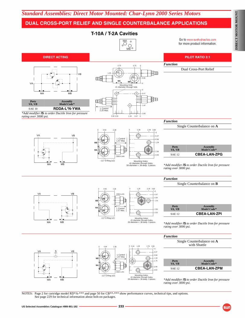
US Selected Assemblies Catalogue #999-901-192 233
Standard Assemblies: Direct Motor Mounted: Char-Lynn 2000 Series Motors
DUAL CROSS-PORT RELIEF AND SINGLE COUNTERBALANCE APPLICATIONS
T-10A / T-2A CavitiesGo to www.sunhydraulics.comfor more product information.
DIRECT ACTING PILOT RATIO 3:1
FunctionDual Cross-Port Relief
PortsVA, VB
AssemblyModel Code*
SAE 10 RDDA-L*N-YWA*Add modifier /S to order Ductile Iron for pressure rating over 3000 psi.
FunctionSingle Counterbalance on A
PortsVA, VB
AssemblyModel Code*
SAE 12 CBEA-LAN-ZPG
*Add modifier /S to order Ductile Iron for pressure rating over 3000 psi.
FunctionSingle Counterbalance on B
PortsVA, VB
AssemblyModel Code*
SAE 12 CBEA-LAN-ZPI
*Add modifier /S to order Ductile Iron for pressure rating over 3000 psi.
FunctionSingle Counterbalance on A
with Shuttle
PortsVA, VB
AssemblyModel Code*
SAE 12 CBEA-LAN-ZPM
*Add modifier /S to order Ductile Iron for pressure rating over 3000 psi.
NOTES: Page 2 for cartridge model RD*A-*** and page 50 for CB**-*** show performance curves, technical tips, and options.See page 229 for technical information about bolt-on packages.
MA
MB
VB
VA
MA MB
0.752.75
1.28
0.66
0
VA
VB
0
00.47
0.47
3.033.50
3.00
0
1.97
1.34
Mounting Hole:.41 diameter through hole.
L Control2.25 Max.
MA MB
0
0.47
1.34
3.03
0 1.28 2.78 3.50
Mounting Holes:.41 diameter through holes,
.59 diameter x .38 deep. 3 places.
0.94
2.56
0 0.94 2.38
L Control1.57 Max.
VA
VB
CBEA-LAN
-117 0-Ring (x2)
MA
MB
VA VB
MBMA
0
0.47
1.34
3.03
0 1.28 2.78 3.50
0.94
2.56
Mounting Holes:.41 diameter through holes,
.59 diameter x .38 deep. 3 places.
L Control1.57 Max.
CBEA-LAN
0 0.94 2.38
VA
VB
-117 0-Ring (x2)
MA
MB
VA VB
MBMA
0
0.47
1.34
3.03
0 1.28 2.78 3.50
0.94
2.56
0.44
1.75
0 0.94 2.38
L Control1.57 Max.
VA
VB
CBEA-LAN
-117 0-Ring (x2)
S
Mounting Holes:.41 diameter through holes,
.59 diameter x .38 deep. 3 places.
MA
MB
VA VB
MBMA
S
DIR
EC
T M
OT
OR
MO
UN
T
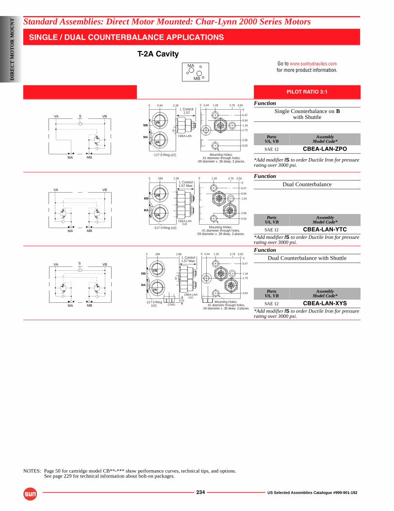
234 US Selected Assemblies Catalogue #999-901-192
Standard Assemblies: Direct Motor Mounted: Char-Lynn 2000 Series Motors
SINGLE / DUAL COUNTERBALANCE APPLICATIONS
T-2A CavityGo to www.sunhydraulics.comfor more product information.
PILOT RATIO 3:1
FunctionSingle Counterbalance on B
with Shuttle
PortsVA, VB
AssemblyModel Code*
SAE 12 CBEA-LAN-ZPO
*Add modifier /S to order Ductile Iron for pressure rating over 3000 psi.
Function
Dual Counterbalance
PortsVA, VB
AssemblyModel Code*
SAE 12 CBEA-LAN-YTC*Add modifier /S to order Ductile Iron for pressure rating over 3000 psi.
FunctionDual Counterbalance with Shuttle
PortsVA, VB
AssemblyModel Code*
SAE 12 CBEA-LAN-XYS*Add modifier /S to order Ductile Iron for pressure rating over 3000 psi.
NOTES: Page 50 for cartridge model CB**-*** show performance curves, technical tips, and options.See page 229 for technical information about bolt-on packages.
MA
MB
VA VB
MBMA
S
0
0.47
1.34
3.03
0 1.28 2.78 3.50
0.94
2.56
0.44
1.75
Mounting Holes:.41 diameter through holes,
.59 diameter x .38 deep. 3 places.
L Control1.57
0 0.94 2.38
VA
VB
CBEA-LAN
-117 0-Ring (x2)
S
MA
MB
VA VB
MBMA
0
0.47
1.34
3.03
0 1.28 2.78 3.50
0.94
2.56
Mounting Holes:.41 diameter through holes,
.59 diameter x .38 deep. 3 places.
0 .094 2.38L Control1.57 Max.
VA
VB
CBEA-LAN(x2)
-117 0-Ring (x2)
MA
MB
VA VB
MBMA
S
0
0.47
1.34
3.03
0 1.28 2.78 3.500.44
1.75
Mounting Holes:.41 diameter through holes,
.59 diameter x .38 deep. 3 places.
0 .094 2.88
VA
VB
-117 0-Ring(x2)
L Control1.57 Max.
CBEA-LAN(x2)
S
0.31CSAD
MA
MB
DIR
EC
T M
OT
OR
MO
UN
T
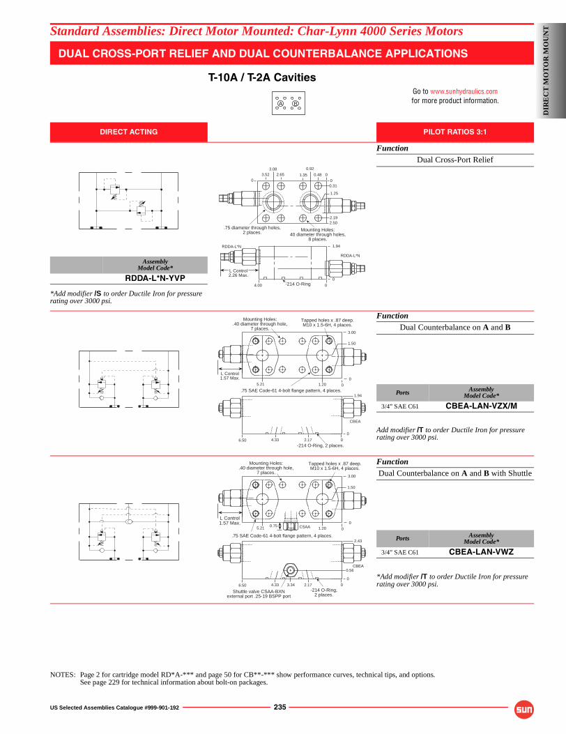
US Selected Assemblies Catalogue #999-901-192 235
Standard Assemblies: Direct Motor Mounted: Char-Lynn 4000 Series Motors
DUAL CROSS-PORT RELIEF AND DUAL COUNTERBALANCE APPLICATIONS
T-10A / T-2A CavitiesGo to www.sunhydraulics.comfor more product information.
DIRECT ACTING PILOT RATIOS 3:1
FunctionDual Cross-Port Relief
AssemblyModel Code*
RDDA-L*N-YVP
*Add modifier /S to order Ductile Iron for pressure rating over 3000 psi.
FunctionDual Counterbalance on A and B
Ports AssemblyModel Code*
3/4” SAE C61 CBEA-LAN-VZX/M
Add modifier /T to order Ductile Iron for pressure rating over 3000 psi.
FunctionDual Counterbalance on A and B with Shuttle
Ports AssemblyModel Code*
3/4” SAE C61 CBEA-LAN-VWZ
*Add modifier /T to order Ductile Iron for pressure rating over 3000 psi.
NOTES: Page 2 for cartridge model RD*A-*** and page 50 for CB**-*** show performance curves, technical tips, and options.See page 229 for technical information about bolt-on packages.
BA
-214 O-Ring
.75 diameter through holes,2 places.
0
Mounting Holes:40 diameter through holes,
8 places.
2.502.19
00.31
1.25
00.481.352.653.52
0.923.08
RDDA-L*N
RDDA-L*N
4.00
1.94
L Control2.26 Max.
0
0
-214 O-Ring, 2 places.
.75 SAE Code-61 4-bolt flange pattern, 4 places.
Mounting Holes:.40 diameter through hole,
7 places.
Tapped holes x .87 deep.M10 x 1.5-6H, 4 places.
0
0
1.94
L Control1.57 Max.
3.00
1.205.21
1.50
CBEA
0
0
4.336.50 2.17
-214 O-Ring,2 places.
Shuttle valve CSAA-BXNexternal port .25-19 BSPP port
.75 SAE Code-61 4-bolt flange pattern, 4 places.
Mounting Holes:.40 diameter through hole,
7 places.
Tapped holes x .87 deep.M10 x 1.5-6H, 4 places.
0
0
3.00
1.205.21 0.75 CSAA
1.50
L Control1.57 Max.
CBEA
3.34 0
0
4.336.50 2.17
2.43
0.56
DIR
EC
T M
OT
OR
MO
UN
T
236 US Selected Assemblies Catalogue #999-901-192
Standard Assemblies: Direct Motor MountedD
IRE
CT
MO
TO
R M
OU
NT
NOTES
US Selected Assemblies Catalogue #999-901-192 237
Applications
The Danfoss gerotor type gear motor is used on a large number of mobile and industrial applications. It is often necessary to incorporate valves in the circuit with the motor to control the flow and pressure. It is also sometimes necessary to incorporate load control valves in the circuit.
It is possible to mount line-mounted valves into the pipework feeding the motor but Sun offers a large range of valves that can be bolted directly onto the motor interface. This eliminates pipework and provides the control directly at the motor.
The use of Sun cartridge valves in these valve assemblies means that in the event of a problem it is a simple task to replace the cartridge rather than have to replace the complete valve.
We are showing a range of bolt-on valve assemblies for the two most common ranges of Danfoss motors, the OMP/OMR range and the OMT range.
Design Concepts and Features
The valve assemblies shown for all sizes of motor are counterbalance valves and cross line relief valves. The counterbalance valves provide load holding and load control while the cross line relief valves provide protection from over pressurisation. The Sun counterbalance valves provide excellent control with low hysteresis and minimum leakage. The relief valves are fast acting with minimum overshoot for excellent protection.
On the smaller sizes of motor, Sun also offers flow control, which can accurately control the motor speed. The type of valve offered is a restrictor type control valve but for more accurate flow control a pressure compensated valve can also be used. Sun also has a further expanded range of bolt on valve assemblies. Consult your local Sun company or distributor for further information.
DIR
EC
T M
OT
OR
MO
UN
TStandard Assemblies
TECHNICAL PRODUCT INFORMATIONDIRECT MOTOR MOUNTED ASSEMBLIESDanfoss (OMP/OMR Series and OMT Series)
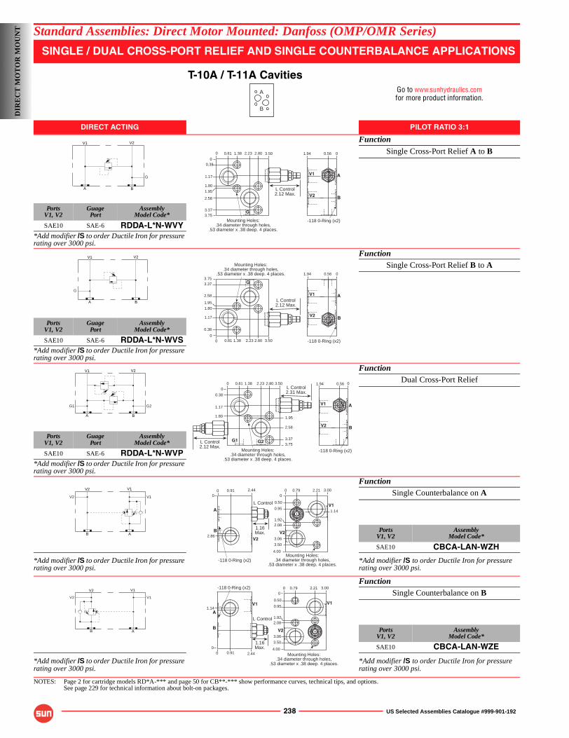
238 US Selected Assemblies Catalogue #999-901-192
Standard Assemblies: Direct Motor Mounted: Danfoss (OMP/OMR Series)
SINGLE / DUAL CROSS-PORT RELIEF AND SINGLE COUNTERBALANCE APPLICATIONS
T-10A / T-11A CavitiesGo to www.sunhydraulics.comfor more product information.
DIRECT ACTING PILOT RATIO 3:1
Function
Single Cross-Port Relief A to B
PortsV1, V2
GuagePort
AssemblyModel Code*
SAE10 SAE-6 RDDA-L*N-WVY*Add modifier /S to order Ductile Iron for pressure rating over 3000 psi.
FunctionSingle Cross-Port Relief B to A
PortsV1, V2
GuagePort
AssemblyModel Code*
SAE10 SAE-6 RDDA-L*N-WVS*Add modifier /S to order Ductile Iron for pressure rating over 3000 psi.
FunctionDual Cross-Port Relief
PortsV1, V2
GuagePort
AssemblyModel Code*
SAE10 SAE-6 RDDA-L*N-WVP*Add modifier /S to order Ductile Iron for pressure rating over 3000 psi.
FunctionSingle Counterbalance on A
PortsV1, V2
AssemblyModel Code*
SAE10 CBCA-LAN-WZH
*Add modifier /S to order Ductile Iron for pressure rating over 3000 psi.
*Add modifier /S to order Ductile Iron for pressure rating over 3000 psi.
FunctionSingle Counterbalance on B
PortsV1, V2
AssemblyModel Code*
SAE10 CBCA-LAN-WZE
*Add modifier /S to order Ductile Iron for pressure rating over 3000 psi.
*Add modifier /S to order Ductile Iron for pressure rating over 3000 psi.
NOTES: Page 2 for cartridge models RD*A-*** and page 50 for CB**-*** show performance curves, technical tips, and options.See page 229 for technical information about bolt-on packages.
A
B
V2V1
A B
G
01.94
AV1
V2 B
-118 0-Ring (x2)
0.56
L Control2.12 Max.
0
0 1.38 3.50
Mounting Holes:.34 diameter through holes,
.53 diameter x .38 deep. 4 places.
0.81
G
2.802.23
0.38
1.17
1.80
3.37
2.58
1.95
3.75
V2V1
A B
G
01.94
A
B
-118 0-Ring (x2)
0.56
V1
V2
1.38 3.500.81 2.802.23
0.38
1.17
1.80
3.37
2.58
1.95
3.75
L Control2.12 Max.
00
G
Mounting Holes:.34 diameter through holes,
.53 diameter x .38 deep. 4 places.
V2V1
A B
G1 G2
1.94 0.56 0
AV1
V2 B
-118 0-Ring (x2)
L Control2.12 Max.
1.38 3.500.81 2.802.23
3.37
2.58
1.95
3.75
L Control2.31 Max.
0.38
1.17
1.80
Mounting Holes:.34 diameter through holes,
.53 diameter x .38 deep. 4 places.
00
G2G1
V1V2
B A
V2 V1
L Control
1.16Max.
2.440.91
2.86
-118 0-Ring (x2)
V2
0
B
A
03.000.79 2.21
0.50
0.95
4.00
3.50
3.06
1.922.08
1.14
Mounting Holes:.34 diameter through holes,
.53 diameter x .38 deep. 4 places.
0
V1
V2
0
B A
V1V2
V2 V1
1.14
1.16Max.
2.440.91
-118 0-Ring (x2)
V1
0
B
A
0
L Control
3.000.79 2.21
0.50
0.95
4.00
3.50
3.06
1.922.08
Mounting Holes:.34 diameter through holes,
.53 diameter x .38 deep. 4 places.
0
V1
V2
0
DIR
EC
T M
OT
OR
MO
UN
T
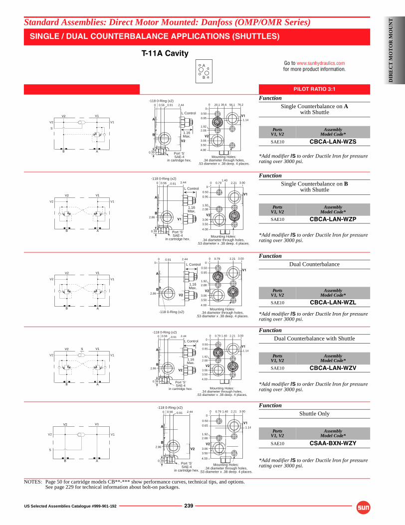
US Selected Assemblies Catalogue #999-901-192 239
Standard Assemblies: Direct Motor Mounted: Danfoss (OMP/OMR Series)
SINGLE / DUAL COUNTERBALANCE APPLICATIONS (SHUTTLES)
T-11A CavityGo to www.sunhydraulics.comfor more product information.
PILOT RATIO 3:1
FunctionSingle Counterbalance on A
with Shuttle
PortsV1, V2
AssemblyModel Code*
SAE10 CBCA-LAN-WZS
*Add modifier /S to order Ductile Iron for pressure rating over 3000 psi.
FunctionSingle Counterbalance on B
with Shuttle
PortsV1, V2
AssemblyModel Code*
SAE10 CBCA-LAN-WZP
*Add modifier /S to order Ductile Iron for pressure rating over 3000 psi.
FunctionDual Counterbalance
PortsV1, V2
AssemblyModel Code*
SAE10 CBCA-LAN-WZL
*Add modifier /S to order Ductile Iron for pressure rating over 3000 psi.
FunctionDual Counterbalance with Shuttle
PortsV1, V2
AssemblyModel Code*
SAE10 CBCA-LAN-WZV
*Add modifier /S to order Ductile Iron for pressure rating over 3000 psi.
FunctionShuttle Only
PortsV1, V2
AssemblyModel Code*
SAE10 CSAA-BXN-WZY
*Add modifier /S to order Ductile Iron for pressure rating over 3000 psi.
NOTES: Page 50 for cartridge models CB**-*** show performance curves, technical tips, and options.See page 229 for technical information about bolt-on packages.
A
B
V1V2
B A
V2 V1
S
1.16Max.
2.440.910.56
Port ‘S’SAE-4
in cartridge hex.
0.39
-118 0-Ring (x2)
V2
0
B
A
L Control
1.14
0
0.50
0.95
4.00
3.50
3.06
1.922.08
Mounting Holes:.34 diameter through holes,
.53 diameter x .38 deep. 4 places.
0 76,2
V1
V2
20,1 56,135,6
V1V2
B A
V2 V1
2.86
1.16Max.
2.440.910.56
Port ‘S’SAE-4
in cartridge hex.
0.39
V1
-118 0-Ring (x2)0
B
A
L Control
Mounting Holes:.34 diameter through holes,
.53 diameter x .38 deep. 4 places.
0
V1
V2
03.000.79 2.21
0.50
0.95
4.00
3.50
3.06
1.922.08
1.40
V1V2
B A
V2 V1
1.16Max.
2.440.91
2.86
-118 0-Ring (x2)
V2
0
B
A
0 L Control
Mounting Holes:.34 diameter through holes,
.53 diameter x .38 deep. 4 places.
0
V1
V2
03.000.79 2.21
0.50
0.95
4.00
3.50
3.06
1.922.08
V1V2
B A
V2 V1
S
Port ‘S’SAE-4
in cartridge hex.
1.16Max.
2.440.91
2.86
0.56
0.39
-118 0-Ring (x2)
V2
0
B
A
L Control
Mounting Holes:.34 diameter through holes,
.53 diameter x .38 deep. 4 places.
0
V1
V2
03.000.79 2.21
0.50
0.95
4.00
3.50
3.06
1.922.08
1.14
1.40
V1V2
B A
V2 V1
S
2.440.91
2.86
0.56
0.39
-118 0-Ring (x2)
V2
0
B
A
Port ‘S’SAE-4
in cartridge hex.
1.14
Mounting Holes:.34 diameter through holes,
.53 diameter x .38 deep. 4 places.
0
V1
V2
03.000.79 2.21
0.50
0.65
4.00
3.50
3.06
1.922.08
1.40
DIR
EC
T M
OT
OR
MO
UN
T
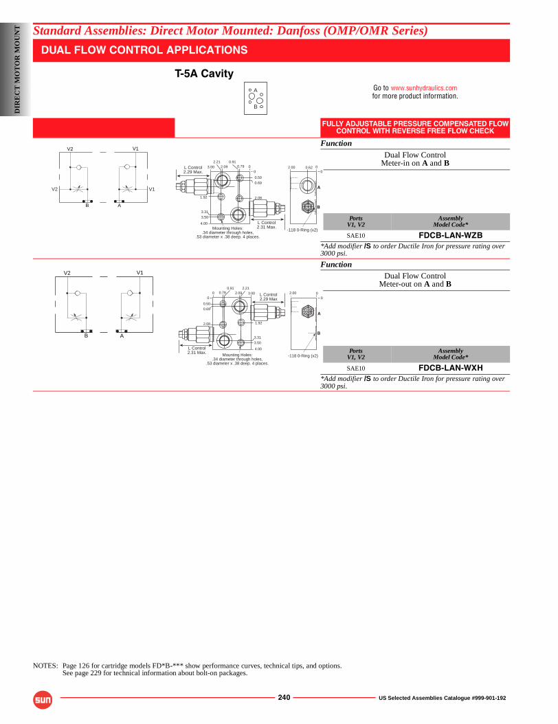
240 US Selected Assemblies Catalogue #999-901-192
Standard Assemblies: Direct Motor Mounted: Danfoss (OMP/OMR Series)
DUAL FLOW CONTROL APPLICATIONS
T-5A CavityGo to www.sunhydraulics.comfor more product information.
FULLY ADJUSTABLE PRESSURE COMPENSATED FLOWCONTROL WITH REVERSE FREE FLOW CHECK
Function
Dual Flow ControlMeter-in on A and B
PortsV1, V2
AssemblyModel Code*
SAE10 FDCB-LAN-WZB*Add modifier /S to order Ductile Iron for pressure rating over 3000 psi.
FunctionDual Flow Control
Meter-out on A and B
PortsV1, V2
AssemblyModel Code*
SAE10 FDCB-LAN-WXH*Add modifier /S to order Ductile Iron for pressure rating over 3000 psi.
NOTES: Page 126 for cartridge models FD*B-*** show performance curves, technical tips, and options.See page 229 for technical information about bolt-on packages.
A
B
V1V2
V2 V1
AB
2.00 0.62 0
A
B
-118 0-Ring (x2)
0
L Control2.31 Max.
3.00 0.792.090.912.21
1.92 2.08
4.00
0.50
0.69
3.31
3.50
Mounting Holes:.34 diameter through holes,
.53 diameter x .38 deep. 4 places.
L Control2.29 Max.
0
0
V1V2
AB
2.00
0
A
B
-118 0-Ring (x2)
0L Control2.29 Max
Mounting Holes:.34 diameter through holes,
.53 diameter x .38 deep. 4 places.
L Control2.31 Max.
00 3.000.79 2.09
0.91 2.21
1.922.08
4.00
0.50
0.69
3.31
3.50
DIR
EC
T M
OT
OR
MO
UN
T
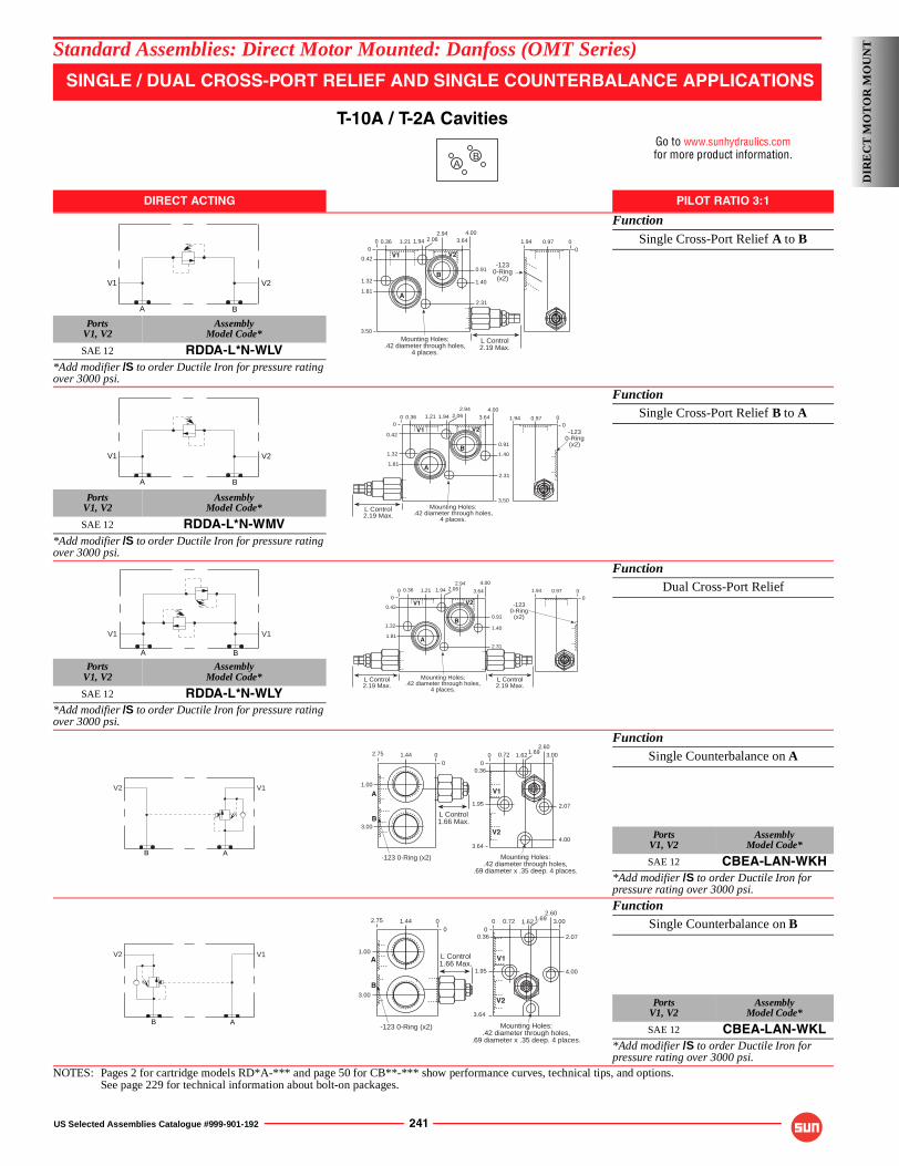
US Selected Assemblies Catalogue #999-901-192 241
Standard Assemblies: Direct Motor Mounted: Danfoss (OMT Series)
SINGLE / DUAL CROSS-PORT RELIEF AND SINGLE COUNTERBALANCE APPLICATIONS
T-10A / T-2A CavitiesGo to www.sunhydraulics.comfor more product information.
DIRECT ACTING PILOT RATIO 3:1
Function
Single Cross-Port Relief A to B
PortsV1, V2
AssemblyModel Code*
SAE 12 RDDA-L*N-WLV*Add modifier /S to order Ductile Iron for pressure rating over 3000 psi.
FunctionSingle Cross-Port Relief B to A
PortsV1, V2
AssemblyModel Code*
SAE 12 RDDA-L*N-WMV*Add modifier /S to order Ductile Iron for pressure rating over 3000 psi.
FunctionDual Cross-Port Relief
PortsV1, V2
AssemblyModel Code*
SAE 12 RDDA-L*N-WLY*Add modifier /S to order Ductile Iron for pressure rating over 3000 psi.
FunctionSingle Counterbalance on A
PortsV1, V2
AssemblyModel Code*
SAE 12 CBEA-LAN-WKH*Add modifier /S to order Ductile Iron for pressure rating over 3000 psi.
FunctionSingle Counterbalance on B
PortsV1, V2
AssemblyModel Code*
SAE 12 CBEA-LAN-WKL*Add modifier /S to order Ductile Iron for pressure rating over 3000 psi.
NOTES: Pages 2 for cartridge models RD*A-*** and page 50 for CB**-*** show performance curves, technical tips, and options.See page 229 for technical information about bolt-on packages.
AB
V2V1
A B
1.21 2.06
L Control2.19 Max.
Mounting Holes:.42 diameter through holes,
4 places.
0.42
1.32
1.81
0.36
0.91
1.40
2.31
1.94 3.644.002.94
3.50
B
A
V1 V2
00
1.94 0.970
0
-1230-Ring
(x2)
V2V1
A B
1.94 0.970-123
0-Ring(x2)
01.21 2.06
L Control2.19 Max.
Mounting Holes:.42 diameter through holes,
4 places.
0.42
1.32
1.81
0.36
0.91
1.40
2.31
1.94 3.644.002.94
3.50
B
A
V1 V2
00
A B
V1 V1
1.94 0.970
-1230-Ring
(x2)
01.21 2.06
L Control2.19 Max.
Mounting Holes:.42 diameter through holes,
4 places.
0.42
1.32
1.81
0.36
0.91
1.40
2.31
1.94 3.64
4.002.94
L Control2.19 Max.
B
A
V1 V2
00
B A
V2 V1
3.64
Mounting Holes:.42 diameter through holes,
.69 diameter x .35 deep. 4 places.
2.07
4.00
1.95
0.36
V1
V2
00
3.000.72 1.62 1.692.60
2.75
3.00
1.00
1.44
L Control1.66 Max.
-123 0-Ring (x2)
B
A
00
B A
V2 V1
2.75
3.00
1.00
1.44
L Control1.66 Max.
-123 0-Ring (x2)
B
A
00
2.07
4.00
Mounting Holes:.42 diameter through holes,
.69 diameter x .35 deep. 4 places.
V1
V2
00
3.64
3.00
1.95
0.72 1.62 1.692.60
0.36
DIR
EC
T M
OT
OR
MO
UN
T
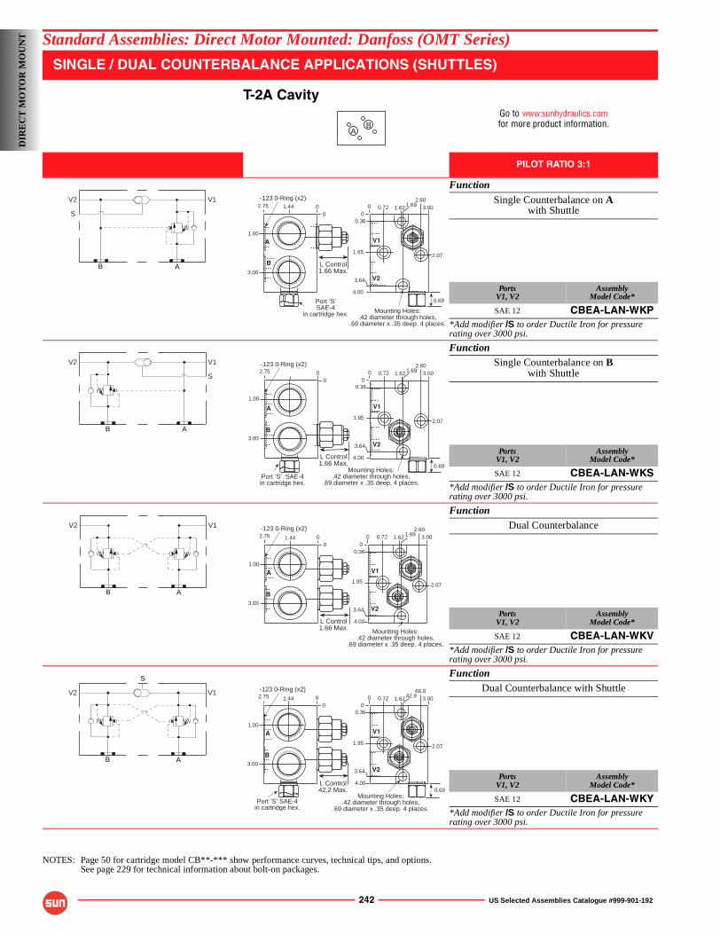
242 US Selected Assemblies Catalogue #999-901-192
Standard Assemblies: Direct Motor Mounted: Danfoss (OMT Series)
SINGLE / DUAL COUNTERBALANCE APPLICATIONS (SHUTTLES)
T-2A CavityGo to www.sunhydraulics.comfor more product information.
PILOT RATIO 3:1
Function
Single Counterbalance on Awith Shuttle
PortsV1, V2
AssemblyModel Code*
SAE 12 CBEA-LAN-WKP*Add modifier /S to order Ductile Iron for pressure rating over 3000 psi.
FunctionSingle Counterbalance on B
with Shuttle
PortsV1, V2
AssemblyModel Code*
SAE 12 CBEA-LAN-WKS*Add modifier /S to order Ductile Iron for pressure rating over 3000 psi.
FunctionDual Counterbalance
PortsV1, V2
AssemblyModel Code*
SAE 12 CBEA-LAN-WKV*Add modifier /S to order Ductile Iron for pressure rating over 3000 psi.
FunctionDual Counterbalance with Shuttle
PortsV1, V2
AssemblyModel Code*
SAE 12 CBEA-LAN-WKY*Add modifier /S to order Ductile Iron for pressure rating over 3000 psi.
NOTES: Page 50 for cartridge model CB**-*** show performance curves, technical tips, and options.See page 229 for technical information about bolt-on packages.
AB
B A
V2 V1
S
L Control1.66 Max.
2.75-123 0-Ring (x2)
3.00
1.00
1.44 00
Port ‘S’SAE-4
in cartridge hex.
B
A
Mounting Holes:.42 diameter through holes,
.69 diameter x .35 deep. 4 places.
V1
V2
00
3.00
2.07
4.00
1.65
0.72 1.62 1.692.60
0.36
3.64
0.69
B A
V2 V1
S
Port ‘S’ SAE-4in cartridge hex.
L Control1.66 Max.
2.75
3.00
1.00
-123 0-Ring (x2)
B
A
00
Mounting Holes:.42 diameter through holes,
.69 diameter x .35 deep. 4 places.
V1
V2
00
3.00
2.07
4.00
1.95
0.72 1.62 1.692.60
0.36
3.64
0.69
B A
V2 V1
L Control1.66 Max.
2.75
3.00
1.00
1.44
-123 0-Ring (x2)
B
A
00
Mounting Holes:.42 diameter through holes,
.69 diameter x .35 deep. 4 places.
V1
V2
00
3.00
2.07
4.00
1.95
0.72 1.62 1.692.60
0.36
3.64
B A
V2 V1
S
L Control42,2 Max.
2.75
3.00
1.00
1.44
-123 0-Ring (x2)
B
A
00
Port ‘S’ SAE-4in cartridge hex.
0.69Mounting Holes:
.42 diameter through holes,.69 diameter x .35 deep. 4 places.
V1
V2
00
3.00
2.07
4.00
1.95
0.72 1.62 42,966,0
0.36
3.64
DIR
EC
T M
OT
OR
MO
UN
T
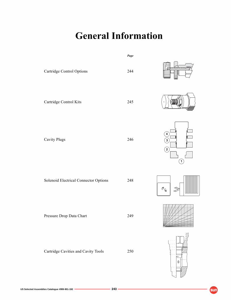
US Selected Assemblies Catalogue #999-901-192 243
1
2
4
3
General Information
Page
Cartridge Control Options 244
Cartridge Control Kits 245
Cavity Plugs 246
Solenoid Electrical Connector Options 248
Pressure Drop Data Chart 249
Cartridge Cavities and Cavity Tools 250
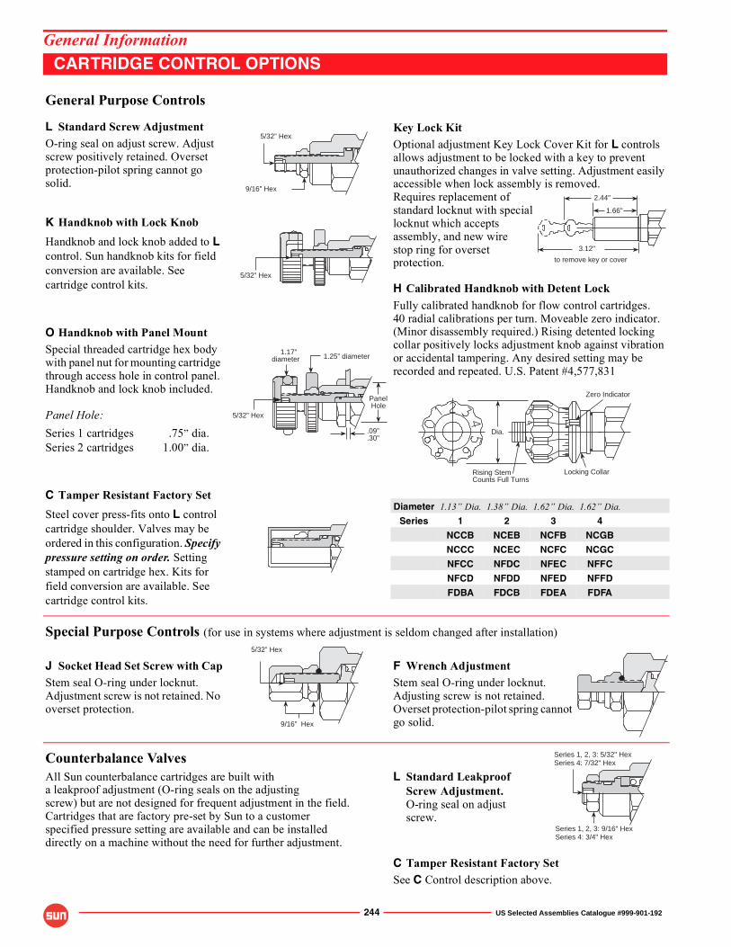
244 US Selected Assemblies Catalogue #999-901-192
General InformationCARTRIDGE CONTROL OPTIONS
General Purpose Controls
L Standard Screw AdjustmentO-ring seal on adjust screw. Adjust screw positively retained. Overset protection-pilot spring cannot go solid.
K Handknob with Lock KnobHandknob and lock knob added to L control. Sun handknob kits for field conversion are available. See cartridge control kits.
O Handknob with Panel MountSpecial threaded cartridge hex body with panel nut for mounting cartridge through access hole in control panel. Handknob and lock knob included.
Panel Hole:Series 1 cartridges .75� dia.Series 2 cartridges 1.00� dia.
C Tamper Resistant Factory SetSteel cover press-fits onto L control cartridge shoulder. Valves may be ordered in this configuration. Specify pressure setting on order. Setting stamped on cartridge hex. Kits for field conversion are available. See cartridge control kits.
Key Lock KitOptional adjustment Key Lock Cover Kit for L controls allows adjustment to be locked with a key to prevent unauthorized changes in valve setting. Adjustment easily accessible when lock assembly is removed.Requires replacement ofstandard locknut with speciallocknut which acceptsassembly, and new wirestop ring for oversetprotection.
H Calibrated Handknob with Detent LockFully calibrated handknob for flow control cartridges.40 radial calibrations per turn. Moveable zero indicator. (Minor disassembly required.) Rising detented locking collar positively locks adjustment knob against vibration or accidental tampering. Any desired setting may be recorded and repeated. U.S. Patent #4,577,831
Diameter 1.13� Dia. 1.38� Dia. 1.62� Dia. 1.62� Dia.Series 1 2 3 4
NCCB NCEB NCFB NCGB
NCCC NCEC NCFC NCGC
NFCC NFDC NFEC NFFC
NFCD NFDD NFED NFFD
FDBA FDCB FDEA FDFA
Special Purpose Controls (for use in systems where adjustment is seldom changed after installation)
J Socket Head Set Screw with Cap F Wrench AdjustmentStem seal O-ring under locknut. Adjustment screw is not retained. No overset protection.
Stem seal O-ring under locknut. Adjusting screw is not retained. Overset protection-pilot spring cannot go solid.
Counterbalance ValvesL Standard Leakproof
Screw Adjustment.O-ring seal on adjustscrew.
All Sun counterbalance cartridges are built witha leakproof adjustment (O-ring seals on the adjustingscrew) but are not designed for frequent adjustment in the field. Cartridges that are factory pre-set by Sun to a customerspecified pressure setting are available and can be installeddirectly on a machine without the need for further adjustment.
C Tamper Resistant Factory SetSee C Control description above.
5/32” Hex
9/16” Hex
5/32” Hex
2.44"
1.66"
3.12"
to remove key or cover
Dia.
Rising StemCounts Full Turns
Locking Collar
Zero Indicator
5/32” Hex
1.17”diameter 1.25” diameter
.09”
.30”
Panel Hole
5/32” Hex
9/16” Hex
Series 1, 2, 3: 5/32" HexSeries 4: 7/32" Hex
Series 1, 2, 3: 9/16" HexSeries 4: 3/4" Hex
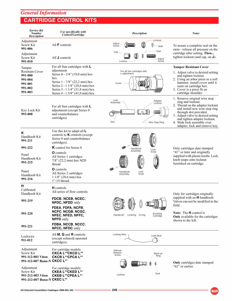
US Selected Assemblies Catalogue #999-901-192 245
General InformationCARTRIDGE CONTROL KITS
Service KitNumber
DescriptionUse specifically with
Control/Cartridge Description Notes
AdjustmentScrew Kit991-006
All F controls To assure a complete seal on the stem - release all pressure on the cartridge after setting. Then... tighten locknut (and cap, on J).
AdjustmentScrew Kit991-010
All J controls
TamperResistant Cover991-000991-004991-001991-002991-003
For all Sun cartridges with L adjustmentSeries 0 - 3/4� (19,0 mm) hex hexSeries 1 - 7/8� (22,2 mm) hexSeries 2 - 1 1/8� (28,6 mm) hexSeries 3 - 1 1/4� (31,8 mm) hexSeries 4 - 1 5/8� (41,0 mm) hex
Tamper Resistant Cover1. Adjust valve to desired setting
and tighten locknut.2. Using an arbor press or a soft
hammer, install cover until it seats on cartridge hex.
3. Cover is a press fit on cartridge shoulder.
Key Lock Kit993-008
For all Sun cartridges with L adjustment (except Series 0 and counterbalance cartridges).
1. Remove original wire stop ring and locknut.
2. Thread on the adapter locknut and install new wire stop ring through slot provided.
3. Adjust valve to desired setting and tighten adapter locknut.
4. Slide lock assembly over adapter, lock and remove key.
KHandknob Kit991-211
Use this kit to adapt all Lcontrols to K controls (except Series 0 and counterbalance cartridges).
Only cartridges date stamped �41� or later and originally supplied with plastic knobs. Lock knob snaps onto locknut furnished on cartridge.
991-222 K control for Series 0
PanelHandknob Kit991-215
O controlsAll Series 1 cartridges7/8� (22,2 mm) hex M20 thread
PanelHandknob Kit991-216
O controlsAll Series 2 cartridges1 1/8� (28,6 mm) hex1�-14 thread
HCalibratedHandknob Kit
H controlsAll series of flow controls Only for cartridges originally
supplied with an H handknob. Valves can not be modified in the field.
Note: The H control isOnly available for the cartridges shown to the left.
991-219 FDCB, NCEB, NCEC,NFDC, NFDD only
991-220
FDEA, FDFA, NCFB, NCFC, NCGB, NCGC, NFEC, NFED, NFFC,NFFD only
991-221 FDBA, NCCB, NCCC,NFCC, NFDC only
Lockwire911-012
All M, Q and R controls(except solenoid operated cartridges).
AdjustmentScrew Kit991-112-003 Viton991-112-007 Buna-N
For cartridge models:CKCA L**CKCD L**CKCB L**CPCA L**CKCC L** Only cartridges date stamped
�62� or earlier.AdjustmentScrew Kit991-212-003 Viton991-212-007 Buna-N
For cartridge models:CKEA L**CKED L**CKEB L**CPEA L**CKEC L**
Cap
Locknut
Seal
AdjustScrew
AdjustScrew
Locknut
Seal
For all Sun cartridges withL-adjustment
Cover
Wire Stop Ring
LockAssembly
Key
AdapterLocknut
HandknobAssembly
LockKnob
HandknobAssembly Lock
Knob
Handknob Lockring O-ringExsistingCartridge
Locking Wire Lead Seal
ManualRelease Screw
Locknut Seal
Back-up Ring
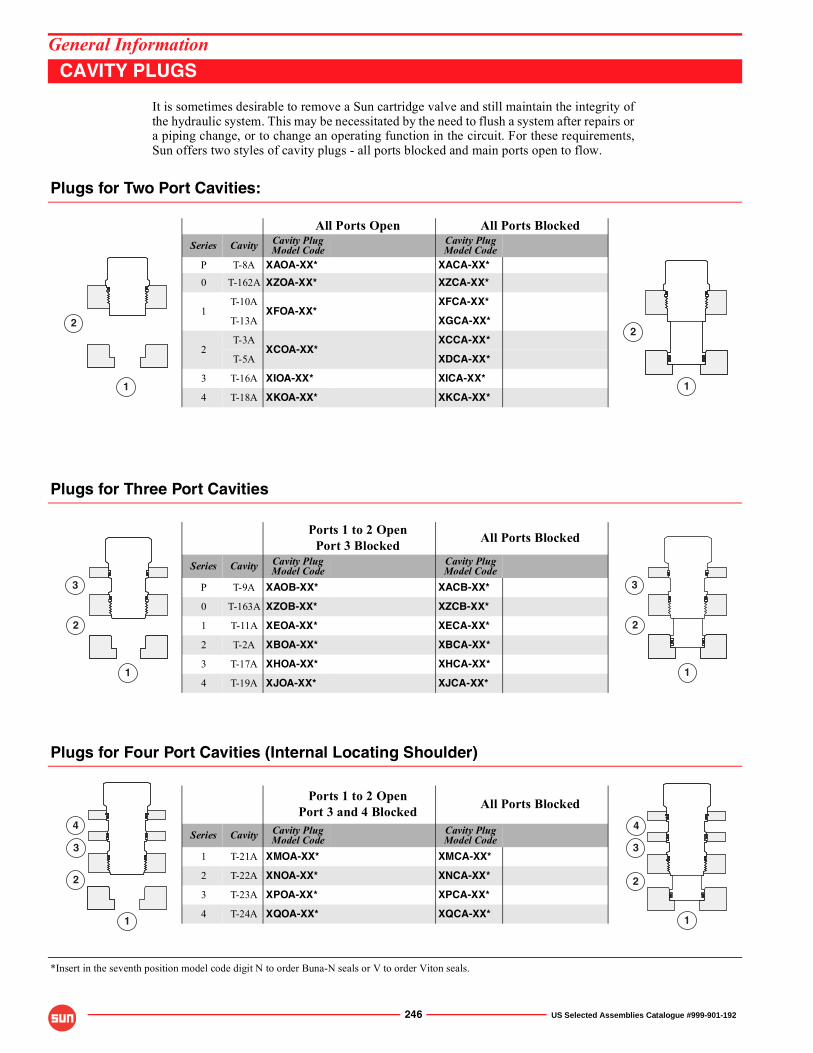
246 US Selected Assemblies Catalogue #999-901-192
General InformationCAVITY PLUGS
It is sometimes desirable to remove a Sun cartridge valve and still maintain the integrity ofthe hydraulic system. This may be necessitated by the need to flush a system after repairs ora piping change, or to change an operating function in the circuit. For these requirements,Sun offers two styles of cavity plugs - all ports blocked and main ports open to flow.
Plugs for Two Port Cavities:
All Ports Open All Ports BlockedSeries Cavity Cavity Plug
Model CodeCavity PlugModel Code
P T-8A XAOA-XX* XACA-XX*
0 T-162A XZOA-XX* XZCA-XX*
1T-10A
XFOA-XX*XFCA-XX*
T-13A XGCA-XX*
2T-3A
XCOA-XX*XCCA-XX*
T-5A XDCA-XX*
3 T-16A XIOA-XX* XICA-XX*
4 T-18A XKOA-XX* XKCA-XX*
Plugs for Three Port Cavities
Ports 1 to 2 OpenPort 3 Blocked All Ports Blocked
Series Cavity Cavity PlugModel Code
Cavity PlugModel Code
P T-9A XAOB-XX* XACB-XX*
0 T-163A XZOB-XX* XZCB-XX*
1 T-11A XEOA-XX* XECA-XX*
2 T-2A XBOA-XX* XBCA-XX*
3 T-17A XHOA-XX* XHCA-XX*
4 T-19A XJOA-XX* XJCA-XX*
Plugs for Four Port Cavities (Internal Locating Shoulder)
Ports 1 to 2 OpenPort 3 and 4 Blocked All Ports Blocked
Series Cavity Cavity PlugModel Code
Cavity PlugModel Code
1 T-21A XMOA-XX* XMCA-XX*
2 T-22A XNOA-XX* XNCA-XX*
3 T-23A XPOA-XX* XPCA-XX*
4 T-24A XQOA-XX* XQCA-XX*
*Insert in the seventh position model code digit N to order Buna-N seals or V to order Viton seals.
2
1 1
2
1
2
3
1
2
3
1
2
4
3
1
2
4
3
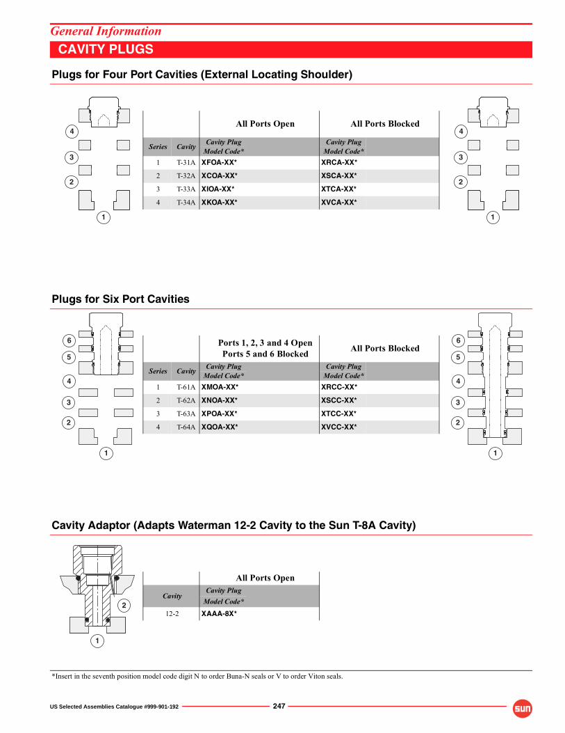
US Selected Assemblies Catalogue #999-901-192 247
General InformationCAVITY PLUGS
Plugs for Four Port Cavities (External Locating Shoulder)
All Ports Open All Ports Blocked
Series Cavity Cavity Plug Cavity PlugModel Code* Model Code*
1 T-31A XFOA-XX* XRCA-XX*
2 T-32A XCOA-XX* XSCA-XX*
3 T-33A XIOA-XX* XTCA-XX*
4 T-34A XKOA-XX* XVCA-XX*
Plugs for Six Port Cavities
Ports 1, 2, 3 and 4 OpenPorts 5 and 6 Blocked All Ports Blocked
Series Cavity Cavity Plug Cavity PlugModel Code* Model Code*
1 T-61A XMOA-XX* XRCC-XX*
2 T-62A XNOA-XX* XSCC-XX*
3 T-63A XPOA-XX* XTCC-XX*
4 T-64A XQOA-XX* XVCC-XX*
Cavity Adaptor (Adapts Waterman 12-2 Cavity to the Sun T-8A Cavity)
All Ports Open
CavityCavity Plug
Model Code*12-2 XAAA-8X*
*Insert in the seventh position model code digit N to order Buna-N seals or V to order Viton seals.
1
2
4
3
1
2
4
3
1
2
4
3
5
6
1
2
4
3
5
6
2
1
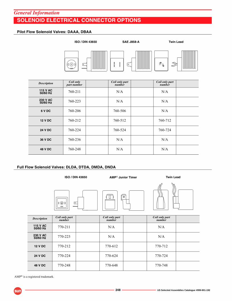
248 US Selected Assemblies Catalogue #999-901-192
General Information SOLENOID ELECTRICAL CONNECTOR OPTIONS
Pilot Flow Solenoid Valves: DAAA, DBAA
Full Flow Solenoid Valves: DLDA, DTDA, DMDA, DNDA
ISO / DIN 43650 SAE J858-A Twin Lead
Description Coil onlypart number
Coil only part number
Coil only part number
115 V AC50/60 Hz 760-211 N/A N/A
230 V AC50/60 Hz 760-223 N/A N/A
6 V DC 760-206 760-506 N/A
12 V DC 760-212 760-512 760-712
24 V DC 760-224 760-524 760-724
36 V DC 760-236 N/A N/A
48 V DC 760-248 N/A N/A
ISO / DIN 43650 AMP® Junior Timer Twin Lead
Description Coil only part number
Coil only part number
Coil only part number
115 V AC50/60 Hz 770-211 N/A N/A
230 V AC50/60 Hz 770-223 N/A N/A
12 V DC 770-212 770-612 770-712
24 V DC 770-224 770-624 770-724
48 V DC 770-248 770-648 770-748
AMP® is a registered trademark.
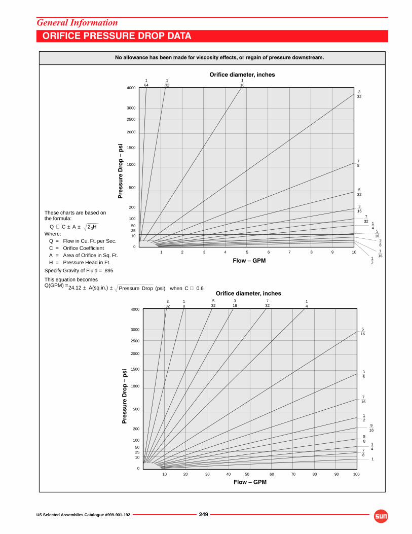
US Selected Assemblies Catalogue #999-901-192 249
General InformationORIFICE PRESSURE DROP DATA
No allowance has been made for viscosity effects, or regain of pressure downstream.
347
8
58
716
38
4000
3000
2500
2000
1500
1000
500
200
100
502510
0
Pre
ssu
re D
rop
– p
si
1 2 3 4 5 6 7 8 9 10
164
132
116
332
18
532
316
732 1
45
1638
716
12
Pre
ssu
re D
rop
– p
si
4000
3000
2500
2000
1500
1000
500
200
100
502510
0
10 20 30 40 50 60 70 80 90 100
332
18
732
14
516
12
916
These charts are based onthe formula:
Where:Q = Flow in Cu. Ft. per Sec.
C = Orifice CoefficientA = Area of Orifice in Sq. Ft.H = Pressure Head in Ft.
Specify Gravity of Fluid = .895
This equation becomesQ(GPM) =
Q ∅ C ± A ± 2gH
Pressure Drop (psi) when C ∅ 0.624.12 ± A(sq.in.) ±
Orifice diameter, inches
Orifice diameter, inches5
323
16
1
Flow – GPM
Flow – GPM
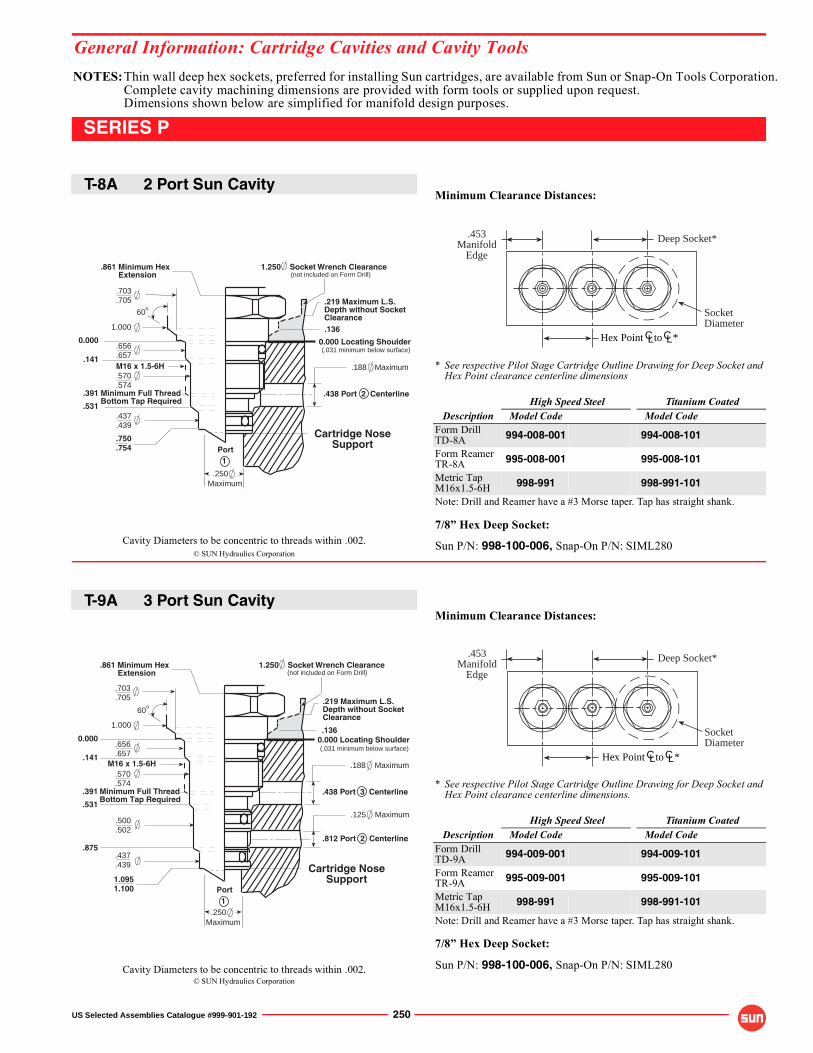
NOTES:Thin wall deep hex sockets, preferred for installing Sun cartridges, are available from Sun or Snap-On Tools Corporation.Complete cavity machining dimensions are provided with form tools or supplied upon request.Dimensions shown below are simplified for manifold design purposes.
© SUN Hydraulics Corporation
© SUN Hydraulics Corporation
Cavity Diameters to be concentric to threads within .002.
Cavity Diameters to be concentric to threads within .002.
General Information: Cartridge Cavities and Cavity Tools
US Selected Assemblies Catalogue #999-901-192 250
SERIES P
Minimum Clearance Distances:
* See respective Pilot Stage Cartridge Outline Drawing for Deep Socket andHex Point clearance centerline dimensions
High Speed Steel Titanium CoatedDescription Model Code Model Code
Form DrillTD-8A 994-008-001 994-008-101
Form ReamerTR-8A 995-008-001 995-008-101
Metric TapM16x1.5-6H 998-991 998-991-101
Note: Drill and Reamer have a #3 Morse taper. Tap has straight shank.
7/8� Hex Deep Socket:
Sun P/N: 998-100-006, Snap-On P/N: SIML280
Minimum Clearance Distances:
* See respective Pilot Stage Cartridge Outline Drawing for Deep Socket andHex Point clearance centerline dimensions.
High Speed Steel Titanium CoatedDescription Model Code Model Code
Form DrillTD-9A 994-009-001 994-009-101
Form ReamerTR-9A 995-009-001 995-009-101
Metric TapM16x1.5-6H 998-991 998-991-101
Note: Drill and Reamer have a #3 Morse taper. Tap has straight shank.
7/8� Hex Deep Socket:
Sun P/N: 998-100-006, Snap-On P/N: SIML280
Deep Socket*
SocketDiameter
.453Manifold
Edge
Hex Point to *CL CL
Deep Socket*
SocketDiameter
.453Manifold
Edge
Hex Point to *CL CL
Minimum Full ThreadBottom Tap Required
0.000 Locating Shoulder0.000
.391
.531
.141
.438 Port 3 Centerline
.188 Maximum
.875.812 Port 2 Centerline
.125 Maximum
Cartridge NoseSupport
(.031 minimum below surface)
.861 Minimum Hex Extension
1.250 Socket Wrench Clearance(not included on Form Drill)
.656
.657
.437
.439
.500
.502
.570
.574
.703
.705
1.0951.100
1.000
.219 Maximum L.S.Depth without SocketClearance
.136
M16 x 1.5-6H
60o
.250Maximum
Port1
Cartridge NoseSupport
0.000 Locating Shoulder
.703
.705
0.000
.570
.574
.437
.439
.391 Minimum Full ThreadBottom Tap Required
.531
.141
.656
.657
.861 Minimum Hex Extension
.438 Port 2 Centerline
.188 Maximum
(.031 minimum below surface)
1.250 Socket Wrench Clearance(not included on Form Drill)
.750
.754
1.000
.219 Maximum L.S.Depth without SocketClearance.136
.250Maximum
M16 x 1.5-6H
60o
Port1
T-8A 2 Port Sun Cavity
T-9A 3 Port Sun Cavity
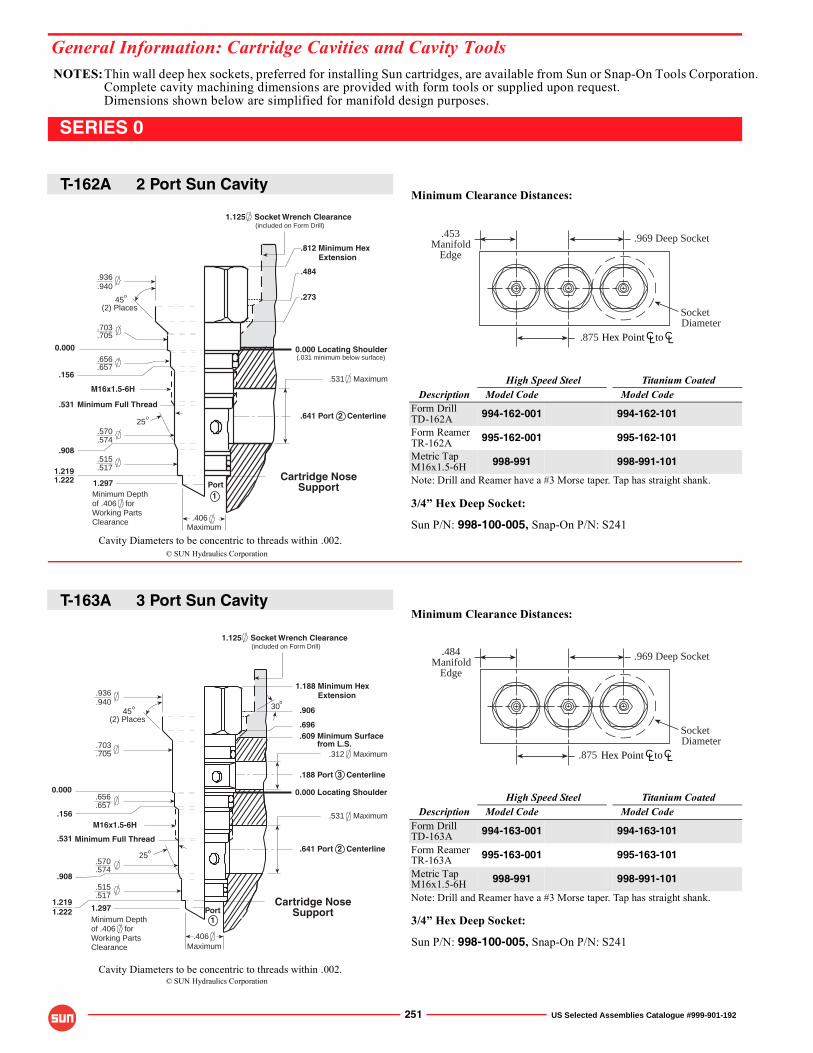
NOTES:Thin wall deep hex sockets, preferred for installing Sun cartridges, are available from Sun or Snap-On Tools Corporation.Complete cavity machining dimensions are provided with form tools or supplied upon request.Dimensions shown below are simplified for manifold design purposes.
General Information: Cartridge Cavities and Cavity Tools
© SUN Hydraulics Corporation
© SUN Hydraulics Corporation
Cavity Diameters to be concentric to threads within .002.
Cavity Diameters to be concentric to threads within .002.
251 US Selected Assemblies Catalogue #999-901-192
SERIES 0
Minimum Clearance Distances:
High Speed Steel Titanium CoatedDescription Model Code Model Code
Form DrillTD-162A 994-162-001 994-162-101
Form ReamerTR-162A 995-162-001 995-162-101
Metric TapM16x1.5-6H 998-991 998-991-101
Note: Drill and Reamer have a #3 Morse taper. Tap has straight shank.
3/4� Hex Deep Socket:
Sun P/N: 998-100-005, Snap-On P/N: S241
Minimum Clearance Distances:
High Speed Steel Titanium CoatedDescription Model Code Model Code
Form DrillTD-163A 994-163-001 994-163-101
Form ReamerTR-163A 995-163-001 995-163-101
Metric TapM16x1.5-6H 998-991 998-991-101
Note: Drill and Reamer have a #3 Morse taper. Tap has straight shank.
3/4� Hex Deep Socket:
Sun P/N: 998-100-005, Snap-On P/N: S241
.969 Deep Socket
SocketDiameter
.453Manifold
Edge
CL CLHex Point to.875
.969 Deep Socket
SocketDiameter
.484Manifold
Edge
.875 CL CLHex Point to
1.297
0.000
Minimum Depthof .406 forWorking PartsClearance
(included on Form Drill)
.641 Port 2 Centerline
1.125 Socket Wrench Clearance
.696
.609 Minimum Surface from L.S.
.906
1.188 Minimum Hex Extension
o
.188 Port 3 Centerline
.312 Maximum
0.000 Locating Shoulder
30
.515
.517
.936
.940
.703
.705
.656
.657
.570
.574
o
.156
.531
.908
.406
.531 Maximum
1.219 Cartridge NoseSupport
Maximum
1Port
45(2) Places
25o
1.222
M16x1.5-6H
Minimum Full Thread
Maximum
.656
.657
.570
.574
.156
.531 Minimum Full Thread
45(2) Places
o
.908
Cartridge NoseSupport
.531 Maximum
0.000 Locating Shoulder
1.125 Socket Wrench Clearance
.812 Minimum Hex Extension
25o
.484
.273
1.2191.222
M16x1.5-6H
.406
1Port
.641 Port 2 Centerline
0.000
1.297Minimum Depthof .406 forWorking PartsClearance
(included on Form Drill)
(.031 minimum below surface)
.936
.940
.705
.703
.515
.517
T-162A 2 Port Sun Cavity
T-163A 3 Port Sun Cavity
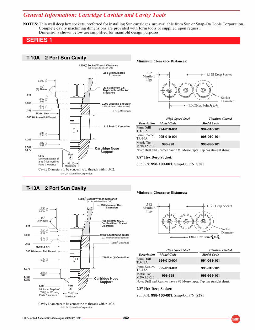
NOTES:Thin wall deep hex sockets, preferred for installing Sun cartridges, are available from Sun or Snap-On Tools Corporation.Complete cavity machining dimensions are provided with form tools or supplied upon request.Dimensions shown below are simplified for manifold design purposes.
© SUN Hydraulics Corporation
© SUN Hydraulics Corporation
Cavity Diameters to be concentric to threads within .002.
Cavity Diameters to be concentric to threads within .002.
General Information: Cartridge Cavities and Cavity Tools
US Selected Assemblies Catalogue #999-901-192 252
SERIES 1
Minimum Clearance Distances:
High Speed Steel Titanium CoatedDescription Model Code Model Code
Form DrillTD-10A 994-010-001 994-010-101
Form ReamerTR-10A 995-010-001 995-010-101
Metric TapM20x1.5-6H 998-998 998-998-101
Note: Drill and Reamer have a #3 Morse taper. Tap has straight shank.
7/8� Hex Deep Socket:
Sun P/N: 998-100-001, Snap-On P/N: S281
Minimum Clearance Distances:
High Speed Steel Titanium CoatedDescription Model Code Model Code
Form DrillTD-13A 994-013-001 994-013-101
Form ReamerTR-13A 995-013-001 995-013-101
Metric TapM20x1.5-6H 998-998 998-998-101
Note: Drill and Reamer have a #3 Morse taper. Tap has straight shank.
7/8� Hex Deep Socket:
Sun P/N: 998-100-001, Snap-On P/N: S281
1.125 Deep Socket
SocketDiameter
.562Manifold
Edge
CL CLHex Point to1.062
.562Manifold
Edge
1.125 Deep Socket
SocketDiameter
CL CLHex Point to1.062
Cartridge NoseSupport
.812 Port 2 Centerline
.875 Maximum
0.000 Locating Shoulder
.688 Minimum Hex Extension
1.250 Socket Wrench Clearance
Maximum.531
.734
1.000
.689
.730
.687
.812
.227
45(3) Places
o
.814
1.266
1.5671.572
.156
.859
.861
.500M20x1.5-6H
Minimum Full Thread
(not included on Form Drill)
(.031 minimum below surface)
.438 Maximum L.S.Depth without SocketClearance
Minimum Depth of.531 for WorkingParts Clearance
Port1
0.000
1.810
.9981.002
.227
.859
.861
1.078
.687
.689
.812
.814
.730
.734
1.3801.385
.156
.500 Minimum Full Thread
M20x1.5-6H
.531Maximum
0.000 Locating Shoulder
1.250 Socket Wrench Clearance
.719 Port 2 Centerline
.688 Maximum
.688 Minimum Hex Extension
(not included on Form Drill)
(.031 minimum below surface)
Cartridge NoseSupport
1Port
45(3) Places
o
.438 Maximum L.S.Depth without SocketClearance
Minimum Depth of.531 for WorkingParts Clearance
0.000
1.59
T-10A 2 Port Sun Cavity
T-13A 2 Port Sun Cavity
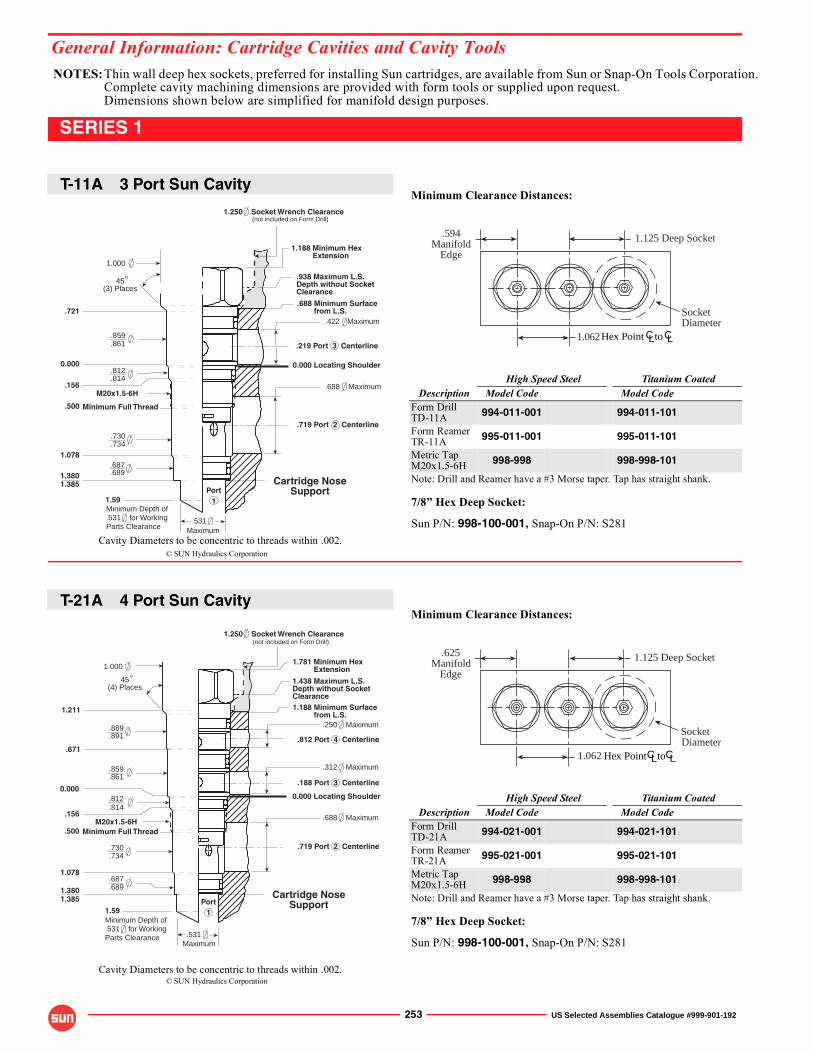
NOTES:Thin wall deep hex sockets, preferred for installing Sun cartridges, are available from Sun or Snap-On Tools Corporation.Complete cavity machining dimensions are provided with form tools or supplied upon request.Dimensions shown below are simplified for manifold design purposes.
General Information: Cartridge Cavities and Cavity Tools
© SUN Hydraulics Corporation
© SUN Hydraulics Corporation
Cavity Diameters to be concentric to threads within .002.
Cavity Diameters to be concentric to threads within .002.
253 US Selected Assemblies Catalogue #999-901-192
SERIES 1
Minimum Clearance Distances:
High Speed Steel Titanium CoatedDescription Model Code Model Code
Form DrillTD-11A 994-011-001 994-011-101
Form ReamerTR-11A 995-011-001 995-011-101
Metric TapM20x1.5-6H 998-998 998-998-101
Note: Drill and Reamer have a #3 Morse taper. Tap has straight shank.
7/8� Hex Deep Socket:
Sun P/N: 998-100-001, Snap-On P/N: S281
Minimum Clearance Distances:
High Speed Steel Titanium CoatedDescription Model Code Model Code
Form DrillTD-21A 994-021-001 994-021-101
Form ReamerTR-21A 995-021-001 995-021-101
Metric TapM20x1.5-6H 998-998 998-998-101
Note: Drill and Reamer have a #3 Morse taper. Tap has straight shank.
7/8� Hex Deep Socket:
Sun P/N: 998-100-001, Snap-On P/N: S281
1.125 Deep Socket
SocketDiameter
.594Manifold
Edge
CL CLHex Point to1.062
1.125 Deep Socket
SocketDiameter
.625Manifold
Edge
1.062 CL CLHex Point to
1Port
1.781 Minimum Hex Extension
1.250 Socket Wrench Clearance
.250 Maximum
.312 Maximum
.688 Maximum
Cartridge NoseSupport
1.188 Minimum Surface from L.S.
.188 Port 3 Centerline
0.000 Locating Shoulder
.719 Port 2 Centerline
.812 Port 4 Centerline
1.000
.671
Minimum Full Thread
1.078.687.689
.812
.814
.730
.734
1.3801.385
.531
1.211
.889
.891
.156
.859
.861
.500
45(4) Places
o
M20x1.5-6H
Maximum
(not included on Form Drill)
1.438 Maximum L.S.Depth without SocketClearance
Minimum Depth of.531 for WorkingParts Clearance
0.000
1.59
1.000
.721
.859
.861
1.078.687.689
.812
.814
.730
.734
1.3801.385
.156
.500
45(3) Places
o
Minimum Full Thread
M20x1.5-6H
.531Maximum
0.000 Locating Shoulder
1.250 Socket Wrench Clearance
.719 Port 2 Centerline
.688 Maximum
.219 Port 3 Centerline
.422 Maximum
.688 Minimum Surface from L.S.
1.188 Minimum Hex Extension
Cartridge NoseSupportPort
1
(not included on Form Drill)
.938 Maximum L.S.Depth without SocketClearance
Minimum Depth of.531 for WorkingParts Clearance
0.000
1.59
T-11A 3 Port Sun Cavity
T-21A 4 Port Sun Cavity
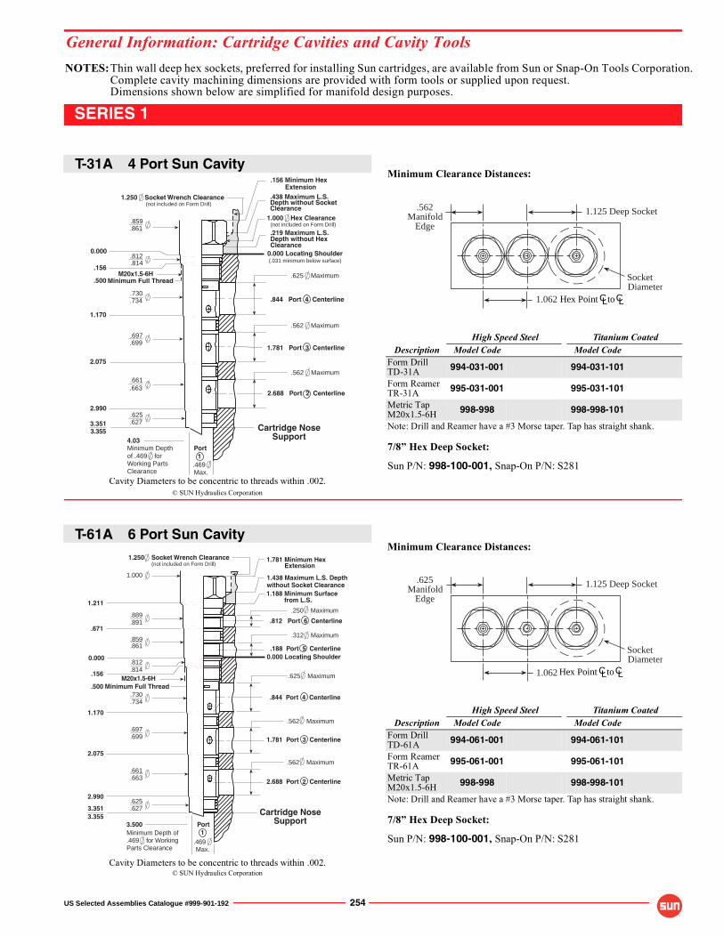
NOTES:Thin wall deep hex sockets, preferred for installing Sun cartridges, are available from Sun or Snap-On Tools Corporation.Complete cavity machining dimensions are provided with form tools or supplied upon request.Dimensions shown below are simplified for manifold design purposes.
© SUN Hydraulics Corporation
© SUN Hydraulics Corporation
Cavity Diameters to be concentric to threads within .002.
Cavity Diameters to be concentric to threads within .002.
General Information: Cartridge Cavities and Cavity Tools
US Selected Assemblies Catalogue #999-901-192 254
SERIES 1
Minimum Clearance Distances:
High Speed Steel Titanium CoatedDescription Model Code Model Code
Form DrillTD-31A 994-031-001 994-031-101
Form ReamerTR-31A 995-031-001 995-031-101
Metric TapM20x1.5-6H 998-998 998-998-101
Note: Drill and Reamer have a #3 Morse taper. Tap has straight shank.
7/8� Hex Deep Socket:
Sun P/N: 998-100-001, Snap-On P/N: S281
Minimum Clearance Distances:
High Speed Steel Titanium CoatedDescription Model Code Model Code
Form DrillTD-61A 994-061-001 994-061-101
Form ReamerTR-61A 995-061-001 995-061-101
Metric TapM20x1.5-6H 998-998 998-998-101
Note: Drill and Reamer have a #3 Morse taper. Tap has straight shank.
7/8� Hex Deep Socket:
Sun P/N: 998-100-001, Snap-On P/N: S281
CL CLHex Point to
1.125 Deep Socket
SocketDiameter
.562Manifold
Edge
1.062
CL CLHex Point to
1.125 Deep Socket
SocketDiameter
.625Manifold
Edge
1.062
Cartridge NoseSupport
0.000 Locating Shoulder
.156 Minimum Hex Extension
Minimum Full Thread
Max..469
1PortMinimum Depth
of .469 forWorking PartsClearance
(.031 minimum below surface)
4.03
1.781 Port 3 Centerline
2.688 Port 2 Centerline
.844 Port 4 Centerline
M20x1.5-6H
1.000 Hex Clearance(not included on Form Drill)
.438 Maximum L.S.Depth without SocketClearance
.219 Maximum L.S.Depth without HexClearance
1.250 Socket Wrench Clearance(not included on Form Drill)
.812
.730
.734
.814
.625
.627
.859
.861
0.000
.156
1.170
2.075
2.990
.500.625 Maximum
.562 Maximum
.562 Maximum.661.663
.697
.699
3.3513.355
2.688 Port 2 Centerline
1.781 Port 3 Centerline
.844 Port 4 Centerline
.188 Port 5 Centerline
.812 Port 6 Centerline
1.250 Socket Wrench Clearance(not included on Form Drill)
Minimum Full Thread.500M20x1.5-6H
1.438 Maximum L.S. Depthwithout Socket Clearance1.188 Minimum Surface from L.S.
Minimum Depth of.469 for WorkingParts Clearance
Cartridge NoseSupport
0.000 Locating Shoulder
1.781 Minimum Hex Extension
Max..469
1Port
.250 Maximum
.312 Maximum
.625 Maximum
.562 Maximum
.562 Maximum
0.000
.625
.627
1.000
.697
.699
.661
.663
.889
.891
.859
.861
.812
.814
.730
.734
1.211
.671
1.170
2.075
2.990
3.3513.355
.156
3.500
T-31A 4 Port Sun Cavity
T-61A 6 Port Sun Cavity
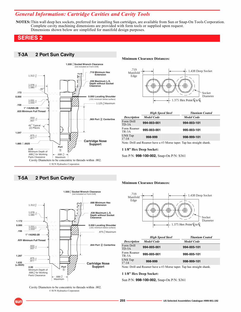
NOTES:Thin wall deep hex sockets, preferred for installing Sun cartridges, are available from Sun or Snap-On Tools Corporation.Complete cavity machining dimensions are provided with form tools or supplied upon request.Dimensions shown below are simplified for manifold design purposes.
General Information: Cartridge Cavities and Cavity Tools
© SUN Hydraulics Corporation
© SUN Hydraulics Corporation
Cavity Diameters to be concentric to threads within .002.
Cavity Diameters to be concentric to threads within .002.
255 US Selected Assemblies Catalogue #999-901-192
SERIES 2
Minimum Clearance Distances:
High Speed Steel Titanium CoatedDescription Model Code Model Code
Form DrillTD-3A 994-003-001 994-003-101
Form ReamerTR-3A 995-003-001 995-003-101
UNS Tap1�-14 998-999 998-999-101
Note: Drill and Reamer have a #3 Morse taper. Tap has straight shank.
1 1/8� Hex Deep Socket:
Sun P/N: 998-100-002, Snap-On P/N: S361
Minimum Clearance Distances:
High Speed Steel Titanium CoatedDescription Model Code Model Code
Form DrillTD-5A 994-005-001 994-005-101
Form ReamerTR-5A 995-005-001 995-005-101
UNS Tap1�-14 998-999 998-999-101
Note: Drill and Reamer have a #3 Morse taper. Tap has straight shank.
1 1/8� Hex Deep Socket:
Sun P/N: 998-100-002, Snap-On P/N: S361
1.438 Deep Socket
SocketDiameter
.719Manifold
Edge
1.375 CL CLHex Point to
1.438 Deep Socket
SocketDiameter
.719Manifold
Edge
CL CLHex Point to1.375
1.0781.080
1.0311.033
.156
.625
.933
.937o
45 Typical(2) Places
1.547.875.877
1.885 .0025+_
1”-14UNS-2B
1.312
1.500 Socket Wrench Clearance
Minimum Full Thread
.969 Port 2 Centerline
0.000 Locating Shoulder
.719 Minimum Hex Extension
1.125 Maximum
.688
Cartridge NoseSupport
Maximum
1Port
.172
60o
(.031 minimum below surface)
(not included on Form Drill)
2.25
.438 Maximum L.S.Depth without SocketClearance
Minimum Depth of.688 for WorkingParts Clearance
0.000
.844 Port 2 Centerline
.875 Maximum
0.000 Locating Shoulder
.688 Minimum Hex Extension
1.500 Socket Wrench Clearance
Maximum.688
.937
.877
.933
.875
1.031
1.312
1.033
1.297
1.635
.156
1.0781.080
.625
1”-14UNS-2B
Minimum Full Thread
(not included on Form Drill)
(.031 minimum below surface)
Port1
Cartridge NoseSupport
.438 Maximum L.S.Depth without SocketClearance
1.172
(±.0025)
Minimum Depth of.688 for WorkingParts Clearance
2.00
0.000
T-3A 2 Port Sun Cavity
T-5A 2 Port Sun Cavity
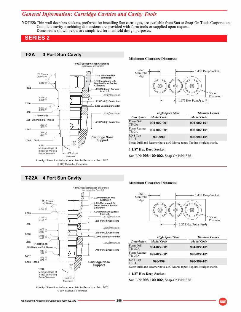
NOTES:Thin wall deep hex sockets, preferred for installing Sun cartridges, are available from Sun or Snap-On Tools Corporation.Complete cavity machining dimensions are provided with form tools or supplied upon request.Dimensions shown below are simplified for manifold design purposes.
© SUN Hydraulics Corporation
© SUN Hydraulics Corporation
Cavity Diameters to be concentric to threads within .002.
Cavity Diameters to be concentric to threads within .002.
General Information: Cartridge Cavities and Cavity Tools
US Selected Assemblies Catalogue #999-901-192 256
SERIES 2
Minimum Clearance Distances:
High Speed Steel Titanium CoatedDescription Model Code Model Code
Form DrillTD-2A 994-002-001 994-002-101
Form ReamerTR-2A 995-002-001 995-002-101
UNS Tap1�-14 998-999 998-999-101
Note: Drill and Reamer have a #3 Morse taper. Tap has straight shank.
1 1/8� Hex Deep Socket:
Sun P/N: 998-100-002, Snap-On P/N: S361
Minimum Clearance Distances:
High Speed Steel Titanium CoatedDescription Model Code Model Code
Form DrillTD-22A 994-022-001 994-022-101
Form ReamerTR-22A 995-022-001 995-022-101
UNS Tap1�-14 998-999 998-999-101
Note: Drill and Reamer have a #3 Morse taper. Tap has straight shank.
1 1/8� Hex Deep Socket:
Sun P/N: 998-100-002, Snap-On P/N: S361
1.438 Deep Socket
SocketDiameter
.750Manifold
Edge
CL CLHex Point to1.375
1.438 Deep Socket
SocketDiameter
.766Manifold
Edge
CL CLHex Point to1.375
1.500 Socket Wrench Clearance
45 Typical(3) Places
1.312
.877
.875
.937
.933
1.0311.033
1.0781.080
o
.156
.625
1.047
1.385 .0025+_
1”-14UNS-2B
.375 Maximum
.688
Cartridge NoseSupport
.719 Minimum Surface from L.S.
Maximum
.719 Port 2 CenterlineMinimum Full Thread
.219 Port 3 Centerline
.625 Maximum
0.000 Locating Shoulder
1.375 Minimum Hex Extension
Port1
.804
(not included on Form Drill)
1.125 Maximum L.S.Depth without SocketClearance
Minimum Depth of.688 for WorkingParts Clearance
0.000
1.781
1.500 Socket Wrench Clearance
1.0311.033
1.312
1.1081.110
1.0801.078
1.383
.156
.625
1.047
.933
.937
.875
.877
o
.688
1.385 .0025+_
45 Typical (4) Places
1”-14UNS-2B
2.000 Minimum Hex Extension
Cartridge NoseSupport
0.000 Locating Shoulder
1.312 Minimum Surface from L.S.
.719 Port 2 Centerline
.312 Maximum
.875 Port 4 Centerline
.312 Maximum
.219 Port 3 Centerline
.625 Maximum
Minimum Full Thread
.688
Maximum
Port1
(not included on Form Drill)
1.719 Maximum L.S.Depth without SocketClearance
Minimum Depth of.688 for WorkingParts Clearance
0.000
1.781
T-2A 3 Port Sun Cavity
T-22A 4 Port Sun Cavity
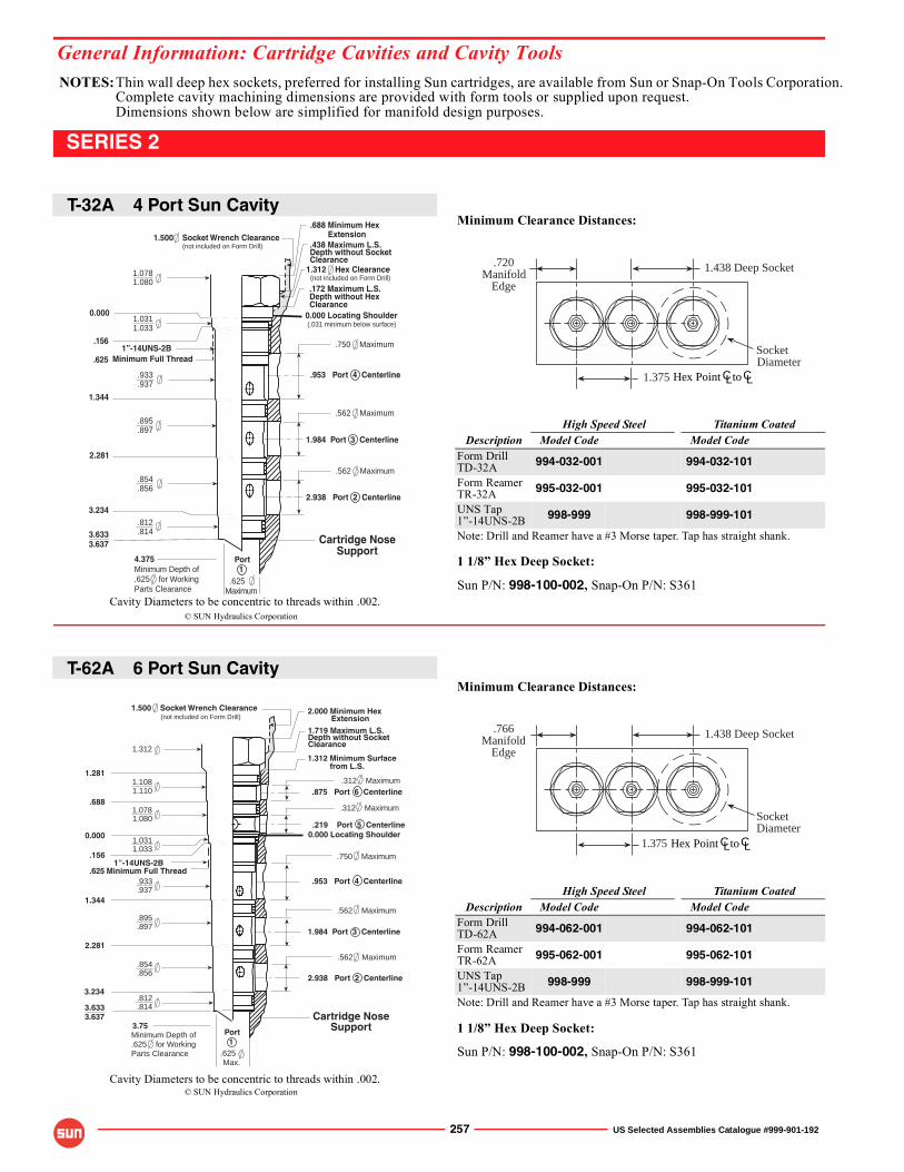
NOTES:Thin wall deep hex sockets, preferred for installing Sun cartridges, are available from Sun or Snap-On Tools Corporation.Complete cavity machining dimensions are provided with form tools or supplied upon request.Dimensions shown below are simplified for manifold design purposes.
General Information: Cartridge Cavities and Cavity Tools
© SUN Hydraulics Corporation
© SUN Hydraulics Corporation
Cavity Diameters to be concentric to threads within .002.
Cavity Diameters to be concentric to threads within .002.
257 US Selected Assemblies Catalogue #999-901-192
SERIES 2
Minimum Clearance Distances:
High Speed Steel Titanium CoatedDescription Model Code Model Code
Form DrillTD-32A 994-032-001 994-032-101
Form ReamerTR-32A 995-032-001 995-032-101
UNS Tap1�-14UNS-2B 998-999 998-999-101
Note: Drill and Reamer have a #3 Morse taper. Tap has straight shank.
1 1/8� Hex Deep Socket:
Sun P/N: 998-100-002, Snap-On P/N: S361
Minimum Clearance Distances:
High Speed Steel Titanium CoatedDescription Model Code Model Code
Form DrillTD-62A 994-062-001 994-062-101
Form ReamerTR-62A 995-062-001 995-062-101
UNS Tap1�-14UNS-2B 998-999 998-999-101
Note: Drill and Reamer have a #3 Morse taper. Tap has straight shank.
1 1/8� Hex Deep Socket:
Sun P/N: 998-100-002, Snap-On P/N: S361
1.438 Deep Socket
SocketDiameter
.720Manifold
Edge
CL CLHex Point to1.375
1.438 Deep Socket
SocketDiameter
.766Manifold
Edge
CL CLHex Point to1.375
Cartridge NoseSupport
0.000 Locating Shoulder
Minimum Full Thread
.688 Minimum Hex Extension
Maximum.625
1Port
1.312 Hex Clearance(not included on Form Drill)
.438 Maximum L.S.Depth without SocketClearance
.172 Maximum L.S.Depth without HexClearance
(.031 minimum below surface)
4.375
2.938 Port 2 Centerline
1.984 Port 3 Centerline
.953 Port 4 Centerline
1”-14UNS-2B
Minimum Depth of.625 for WorkingParts Clearance
1.500 Socket Wrench Clearance(not included on Form Drill)
.750 Maximum
.625
.933
.937
.156
1.344
2.281
3.234.812.814
1.0781.080
1.0311.033
3.6333.637
0.000
.562 Maximum
.562 Maximum
.895
.897
.854
.856
1.281
0.000
.688
.156
(not included on Form Drill)
.219 Port 5 Centerline
.875 Port 6 Centerline
1.500 Socket Wrench Clearance
2.938 Port 2 Centerline
1.984 Port 3 Centerline
.953 Port 4 Centerline
3.6333.637
1”-14UNS-2B
1.719 Maximum L.S.Depth without SocketClearance
Minimum Depth of.625 for WorkingParts Clearance
1.312 Minimum Surface from L.S.
Cartridge NoseSupport
0.000 Locating Shoulder
2.000 Minimum Hex Extension
Minimum Full Thread
Max..625
1Port
.312 Maximum
.312 Maximum
.625
1.344
2.281
3.234
.750 Maximum
.562 Maximum
.562 Maximum
1.312
.854
.856
.812
.814
.895
.897
.933
.937
1.0311.033
1.1081.110
1.0781.080
3.75
T-32A 4 Port Sun Cavity
T-62A 6 Port Sun Cavity
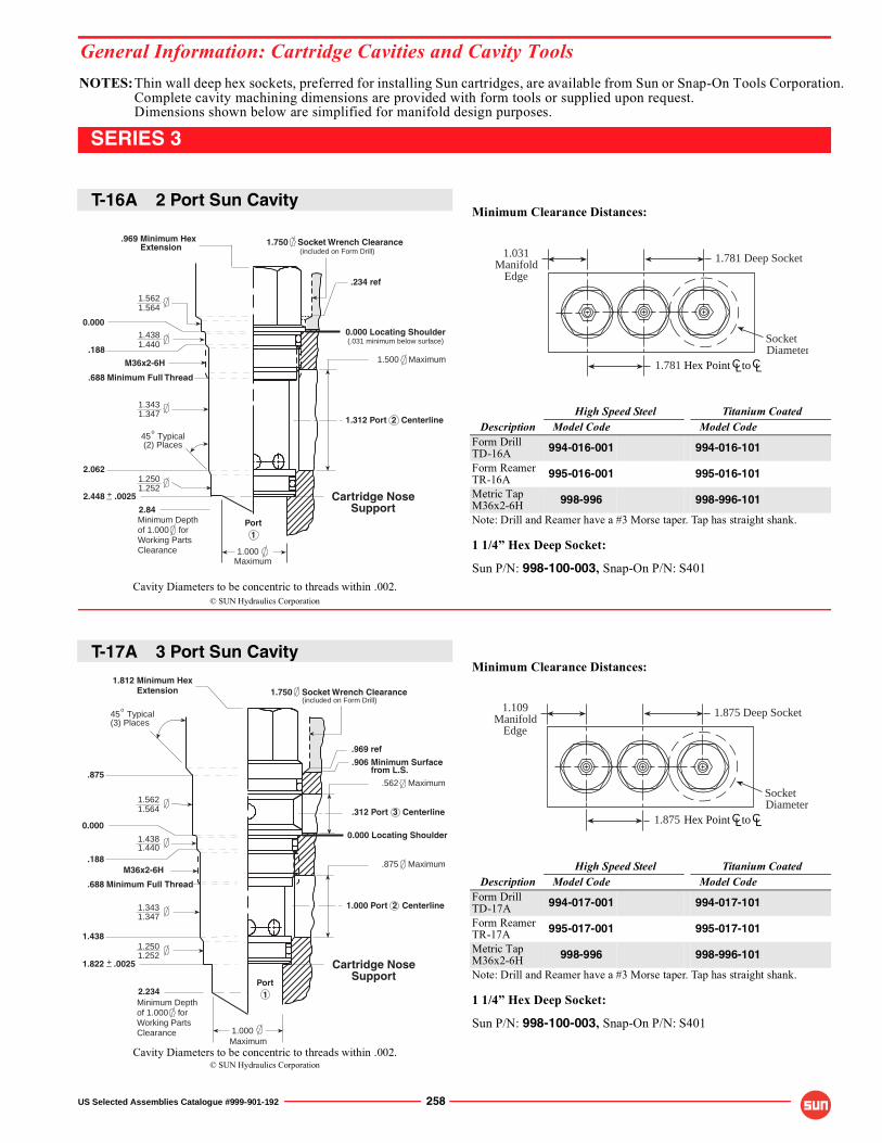
NOTES:Thin wall deep hex sockets, preferred for installing Sun cartridges, are available from Sun or Snap-On Tools Corporation.Complete cavity machining dimensions are provided with form tools or supplied upon request.Dimensions shown below are simplified for manifold design purposes.
© SUN Hydraulics Corporation
© SUN Hydraulics Corporation
Cavity Diameters to be concentric to threads within .002.
Cavity Diameters to be concentric to threads within .002.
General Information: Cartridge Cavities and Cavity Tools
US Selected Assemblies Catalogue #999-901-192 258
SERIES 3
Minimum Clearance Distances:
High Speed Steel Titanium CoatedDescription Model Code Model Code
Form DrillTD-16A 994-016-001 994-016-101
Form ReamerTR-16A 995-016-001 995-016-101
Metric TapM36x2-6H 998-996 998-996-101
Note: Drill and Reamer have a #3 Morse taper. Tap has straight shank.
1 1/4� Hex Deep Socket:
Sun P/N: 998-100-003, Snap-On P/N: S401
Minimum Clearance Distances:
High Speed Steel Titanium CoatedDescription Model Code Model Code
Form DrillTD-17A 994-017-001 994-017-101
Form ReamerTR-17A 995-017-001 995-017-101
Metric TapM36x2-6H 998-996 998-996-101
Note: Drill and Reamer have a #3 Morse taper. Tap has straight shank.
1 1/4� Hex Deep Socket:
Sun P/N: 998-100-003, Snap-On P/N: S401
1.781 Deep Socket
SocketDiameter
1.031Manifold
Edge
CL CLHex Point to1.781
1.875 Deep Socket
SocketDiameter
1.109Manifold
Edge
CL CLHex Point to1.8750.000
2.234Minimum Depthof 1.000 forWorking PartsClearance
1.2501.252
1.3471.343
1.4381.440
1.5641.562
45 Typical(3) Places
.688
1.822 .0025
.875
+_
.188
1.438
o
M36x2-6H
Minimum Full Thread
1.000Maximum
Cartridge NoseSupport
1.812 Minimum Hex Extension
1.000 Port 2 Centerline
.875 Maximum
0.000 Locating Shoulder
.562 Maximum
.906 Minimum Surface from L.S.
.312 Port 3 Centerline
1.750 Socket Wrench Clearance
Port1
.969 ref
(included on Form Drill)
0.000
Minimum Depthof 1.000 forWorking PartsClearance
1.2501.252
1.3471.343
1.4381.440
1.5641.562
2.448 .0025
.188
.688
45 Typical (2) Places
o
2.062
+_
M36x2-6H
Minimum Full Thread
0.000 Locating Shoulder
1.750 Socket Wrench Clearance.969 Minimum Hex Extension
Cartridge NoseSupport
1.500 Maximum
1.000Maximum
1.312 Port 2 Centerline
Port1
.234 ref
(included on Form Drill)
(.031 minimum below surface)
2.84
T-16A 2 Port Sun Cavity
T-17A 3 Port Sun Cavity
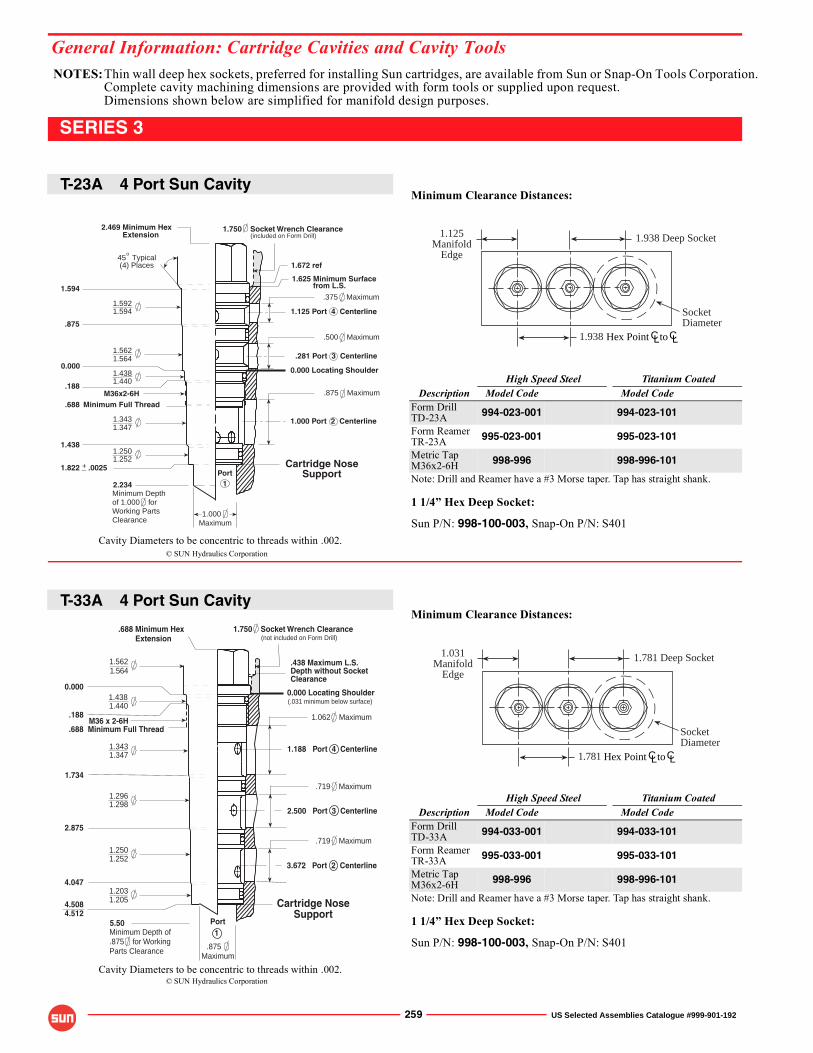
NOTES:Thin wall deep hex sockets, preferred for installing Sun cartridges, are available from Sun or Snap-On Tools Corporation.Complete cavity machining dimensions are provided with form tools or supplied upon request.Dimensions shown below are simplified for manifold design purposes.
General Information: Cartridge Cavities and Cavity Tools
© SUN Hydraulics Corporation
© SUN Hydraulics Corporation
Cavity Diameters to be concentric to threads within .002.
Cavity Diameters to be concentric to threads within .002.
259 US Selected Assemblies Catalogue #999-901-192
SERIES 3
Minimum Clearance Distances:
High Speed Steel Titanium CoatedDescription Model Code Model Code
Form DrillTD-23A 994-023-001 994-023-101
Form ReamerTR-23A 995-023-001 995-023-101
Metric TapM36x2-6H 998-996 998-996-101
Note: Drill and Reamer have a #3 Morse taper. Tap has straight shank.
1 1/4� Hex Deep Socket:
Sun P/N: 998-100-003, Snap-On P/N: S401
Minimum Clearance Distances:
High Speed Steel Titanium CoatedDescription Model Code Model Code
Form DrillTD-33A 994-033-001 994-033-101
Form ReamerTR-33A 995-033-001 995-033-101
Metric TapM36x2-6H 998-996 998-996-101
Note: Drill and Reamer have a #3 Morse taper. Tap has straight shank.
1 1/4� Hex Deep Socket:
Sun P/N: 998-100-003, Snap-On P/N: S401
1.938 Deep Socket
SocketDiameter
1.125Manifold
Edge
CL CLHex Point to1.938
CL CLHex Point to
1.781 Deep Socket
SocketDiameter
1.031Manifold
Edge
1.781
Minimum Depthof 1.000 forWorking PartsClearance
(included on Form Drill)1.750 Socket Wrench Clearance
1.4381.440
1.2521.250
1.3471.343
1.5641.562
1.5941.592
1.822 .0025
.188
.688
o
1.594
.875
1.438
+_
M36x2-6H
45 Typical (4) Places
2.469 Minimum Hex Extension
Minimum Full Thread
PortCartridge Nose
Support1
1.000
0.000 Locating Shoulder
.500 Maximum
1.625 Minimum Surface from L.S.
1.000 Port 2 Centerline
.375 Maximum
1.125 Port 4 Centerline
.875 Maximum
Maximum
1.672 ref
0.000
2.234
.281 Port 3 Centerline
Cartridge NoseSupport
0.000 Locating Shoulder
1.750 Socket Wrench Clearance.688 Minimum Hex Extension
Maximum.875
1Port
Minimum Full Thread
(not included on Form Drill)
3.672 Port 2 Centerline
2.500 Port 3 Centerline
1.188 Port 4 Centerline
(.031 minimum below surface)
M36 x 2-6H
Minimum Depth of.875 for WorkingParts Clearance
.438 Maximum L.S.Depth without SocketClearance
4.508
1.4381.440
.688
1.203
1.734
1.5621.564
0.000
4.047
.188
2.875
4.512
1.205
1.062 Maximum
.719 Maximum
.719 Maximum
5.50
1.3431.347
1.2961.298
1.2501.252
T-23A 4 Port Sun Cavity
T-33A 4 Port Sun Cavity
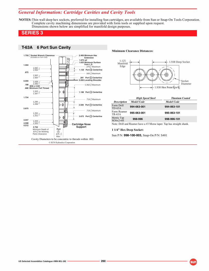
NOTES:Thin wall deep hex sockets, preferred for installing Sun cartridges, are available from Sun or Snap-On Tools Corporation.Complete cavity machining dimensions are provided with form tools or supplied upon request.Dimensions shown below are simplified for manifold design purposes.
General Information: Cartridge Cavities and Cavity Tools
© SUN Hydraulics CorporationCavity Diameters to be concentric to threads within .002.
US Selected Assemblies Catalogue #999-901-192 260
SERIES 3
Minimum Clearance Distances:
High Speed Steel Titanium CoatedDescription Model Code Model Code
Form DrillTD-63A 994-063-001 994-063-101
Form ReamerTR-63A 995-063-001 995-063-101
Metric TapM36x2-6H 998-996 998-996-101
Note: Drill and Reamer have a #3 Morse taper. Tap has straight shank.
1 1/4� Hex Deep Socket:
Sun P/N: 998-100-003, Snap-On P/N: S401
CL CLHex Point to
1.938 Deep Socket
SocketDiameter
1.125Manifold
Edge
1.938
Cartridge NoseSupport
0.000 Locating Shoulder
2.469 Minimum Hex Extension
Minimum Full Thread
Max..875
1Port
1.625 Minimum Surface from L.S.
1.672 ref
0.000
.688
.875
1.594
1.734
2.875
4.047
4.5084.512
1.5621.564
.188
1.4381.440
1.3431.347
1.2031.205
1.750 Socket Wrench Clearance
1.2501.252
1.2961.298
1.5921.594
(included on Form Drill)
2.500 Port 3 Centerline
1.188 Port 4 Centerline
.281 Port 5 Centerline
3.672 Port 2 Centerline
1.125 Port 6 Centerline
M36 x 2-6H
Minimum Depth of.875 for WorkingParts Clearance
.375 Maximum
.500 Maximum
1.062 Maximum
.719 Maximum
.719 Maximum
4.750
T-63A 6 Port Sun Cavity
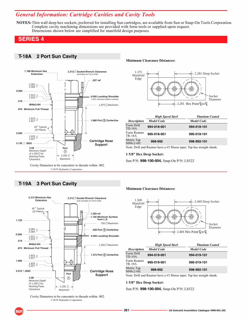
NOTES:Thin wall deep hex sockets, preferred for installing Sun cartridges, are available from Sun or Snap-On Tools Corporation.Complete cavity machining dimensions are provided with form tools or supplied upon request.Dimensions shown below are simplified for manifold design purposes.
General Information: Cartridge Cavities and Cavity Tools
© SUN Hydraulics Corporation
© SUN Hydraulics Corporation
Cavity Diameters to be concentric to threads within .002.
Cavity Diameters to be concentric to threads within .002.
261 US Selected Assemblies Catalogue #999-901-192
SERIES 4
Minimum Clearance Distances:
High Speed Steel Titanium CoatedDescription Model Code Model Code
Form DrillTD-18A 994-018-001 994-018-101
Form ReamerTR-18A 995-018-001 995-018-101
Metric TapM48x2-6H 998-992 998-992-101
Note: Drill and Reamer have a #3 Morse taper. Tap has straight shank.
1 5/8� Hex Deep Socket:
Sun P/N: 998-100-004, Snap-On P/N: LS522
Minimum Clearance Distances:
High Speed Steel Titanium CoatedDescription Model Code Model Code
Form DrillTD-19A 994-019-001 994-019-101
Form ReamerTR-19A 995-019-001 995-019-101
Metric TapM48x2-6H 998-992 998-992-101
Note: Drill and Reamer have a #3 Morse taper. Tap has straight shank.
1 5/8� Hex Deep Socket:
Sun P/N: 998-100-004, Snap-On P/N: LS522
2.281 Deep Socket
SocketDiameter
1.375Manifold
Edge
CL CLHex Point to2.281
2.469 Deep Socket
SocketDiameter
1.500Manifold
Edge
CL CLHex Point to2.469
Minimum Depthof 1.250 forWorking PartsClearance
(.031 minimum below surface)
(included on Form Drill)
3.59
1.9121.914
1.6251.627
1.8171.813
2.0622.064
.219
.875
45 Typical (2) Places
o
3.135 .0025+_
2.594
M48x2-6H
Minimum Full Thread
1.250
1.188 Minimum Hex Extension
Maximum
Cartridge NoseSupport
1.688 Port 2 Centerline
1.875 Maximum
0.000 Locating Shoulder
2.312 Socket Wrench Clearance
Port1
.297 ref
0.000
Minimum Depthof 1.250 forWorking PartsClearance
(not included on Form Drill)
Cartridge NoseSupport
1.375 Port 2 Centerline
1.250 Maximum
0.000 Locating Shoulder
.438 Port 3 Centerline
.750 Maximum
2.312 Socket Wrench Clearance2.312 Minimum Hex Extension
1.156 Minimum Surface from L.S.
1.9121.914
1.8171.813
2.0642.062
1.6271.625
45 Typical (3) Places
o
Minimum Full Thread.875
1.250
2.510 .0025
1.125
.219
1.969
+_
M48x2-6H
Maximum
Port
1
1.250 ref
0.000
2.98
T-18A 2 Port Sun Cavity
T-19A 3 Port Sun Cavity
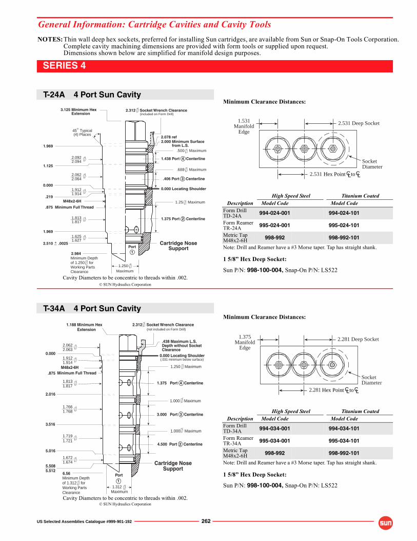
NOTES:Thin wall deep hex sockets, preferred for installing Sun cartridges, are available from Sun or Snap-On Tools Corporation.Complete cavity machining dimensions are provided with form tools or supplied upon request.Dimensions shown below are simplified for manifold design purposes.
© SUN Hydraulics Corporation
© SUN Hydraulics Corporation
Cavity Diameters to be concentric to threads within .002.
Cavity Diameters to be concentric to threads within .002.
General Information: Cartridge Cavities and Cavity Tools
US Selected Assemblies Catalogue #999-901-192 262
SERIES 4
Minimum Clearance Distances:
High Speed Steel Titanium CoatedDescription Model Code Model Code
Form DrillTD-24A 994-024-001 994-024-101
Form ReamerTR-24A 995-024-001 995-024-101
Metric TapM48x2-6H 998-992 998-992-101
Note: Drill and Reamer have a #3 Morse taper. Tap has straight shank.
1 5/8� Hex Deep Socket:
Sun P/N: 998-100-004, Snap-On P/N: LS522
Minimum Clearance Distances:
High Speed Steel Titanium CoatedDescription Model Code Model Code
Form DrillTD-34A 994-034-001 994-034-101
Form ReamerTR-34A 995-034-001 995-034-101
Metric TapM48x2-6H 998-992 998-992-101
Note: Drill and Reamer have a #3 Morse taper. Tap has straight shank.
1 5/8� Hex Deep Socket:
Sun P/N: 998-100-004, Snap-On P/N: LS522
2.531 Deep Socket
SocketDiameter
1.531Manifold
Edge
CL CLHex Point to2.531
CL CLHex Point to
2.281 Deep Socket
SocketDiameter
1.375Manifold
Edge
2.281
Minimum Depthof 1.250 forWorking PartsClearance
(included on Form Drill)
1.6251.627
1.8171.813
2.0622.064
2.0942.092
1.969
.219
.875
1.969
3.125 Minimum Hex Extension
o45 Typical (4) Places
1.125
1.9121.914
2.510 .0025+_
Minimum Full Thread
M48x2-6H
1.250
Cartridge NoseSupport
1.375 Port 2 Centerline
1.25 Maximum
0.000 Locating Shoulder
.406 Port 3 Centerline
.688 Maximum
2.000 Minimum Surface from L.S.
1.438 Port 4 Centerline
.500 Maximum
2.312 Socket Wrench Clearance
Port1
0.000
2.984
Maximum
2.078 ref
Cartridge NoseSupport
0.000 Locating Shoulder
2.312 Socket Wrench Clearance1.188 Minimum Hex Extension
Minimum Full Thread
Maximum1.312
1Port
Minimum Depthof 1.312 forWorking PartsClearance
(not included on Form Drill)
4.500 Port 2 Centerline
3.000 Port 3 Centerline
1.375 Port 4 Centerline
(.031 minimum below surface)
M48x2-6H
.438 Maximum L.S.Depth without SocketClearance
2.0622.063
.875
1.8131.817
0.000
2.016
3.516
5.016
1.6721.674
1.9121.914
1.250 Maximum
5.5085.512
1.000 Maximum
1.000 Maximum
6.56
1.7661.768
1.7191.721
T-24A 4 Port Sun Cavity
T-34A 4 Port Sun Cavity
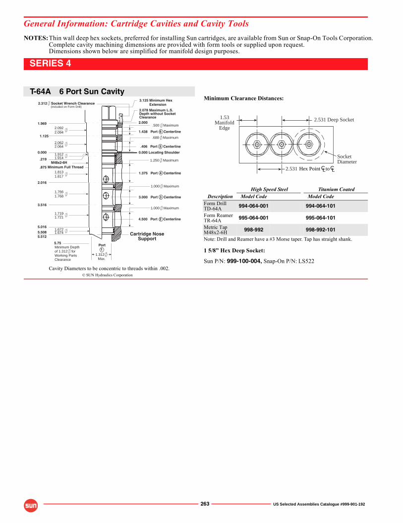
NOTES:Thin wall deep hex sockets, preferred for installing Sun cartridges, are available from Sun or Snap-On Tools Corporation.Complete cavity machining dimensions are provided with form tools or supplied upon request.Dimensions shown below are simplified for manifold design purposes.
General Information: Cartridge Cavities and Cavity Tools
© SUN Hydraulics CorporationCavity Diameters to be concentric to threads within .002.
263 US Selected Assemblies Catalogue #999-901-192
SERIES 4
Minimum Clearance Distances:
High Speed Steel Titanium CoatedDescription Model Code Model Code
Form DrillTD-64A 994-064-001 994-064-101
Form ReamerTR-64A 995-064-001 995-064-101
Metric TapM48x2-6H 998-992 998-992-101
Note: Drill and Reamer have a #3 Morse taper. Tap has straight shank.
1 5/8� Hex Deep Socket:
Sun P/N: 999-100-004, Snap-On P/N: LS522
CL CLHex Point to
2.531 Deep Socket
SocketDiameter
1.53Manifold
Edge
2.531
0.000 Locating Shoulder
Cartridge NoseSupport
3.125 Minimum Hex Extension
Minimum Full Thread
Max.1.312
1PortMinimum Depth
of 1.312 forWorking PartsClearance
4.500 Port 2 Centerline
3.000 Port 3 Centerline
1.375 Port 4 Centerline
1.438 Port 6 Centerline
.406 Port 5 Centerline
M48x2-6H
2.078 Maximum L.S.Depth without SocketClearance
2.312 Socket Wrench Clearance(included on Form Drill)
.500 Maximum
.688 Maximum
1.250 Maximum
1.000 Maximum
1.000 Maximum
5.75
5.016
0.000
.875
1.969
1.125
2.016
3.516
5.5085.512
2.000
.219
1.8131.817
1.7661.768
2.0922.094
2.0622.064
1.9121.914
1.7191.721
1.6721.674
T-64A 6 Port Sun Cavity
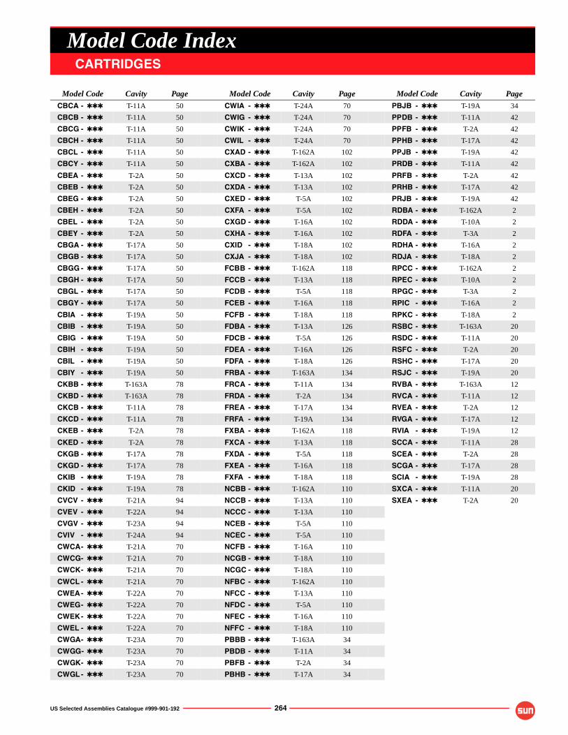
US Selected Assemblies Catalogue #999-901-192 264
Model Code IndexCARTRIDGES
Model Code Cavity Page Model Code Cavity Page Model Code Cavity Page
CBCA - ✱✱✱ T-11A 50 CWIA - ✱✱✱ T-24A 70 PBJB - ✱✱✱ T-19A 34
CBCB - ✱✱✱ T-11A 50 CWIG - ✱✱✱ T-24A 70 PPDB - ✱✱✱ T-11A 42
CBCG - ✱✱✱ T-11A 50 CWIK - ✱✱✱ T-24A 70 PPFB - ✱✱✱ T-2A 42
CBCH - ✱✱✱ T-11A 50 CWIL - ✱✱✱ T-24A 70 PPHB - ✱✱✱ T-17A 42
CBCL - ✱✱✱ T-11A 50 CXAD - ✱✱✱ T-162A 102 PPJB - ✱✱✱ T-19A 42
CBCY - ✱✱✱ T-11A 50 CXBA - ✱✱✱ T-162A 102 PRDB - ✱✱✱ T-11A 42
CBEA - ✱✱✱ T-2A 50 CXCD - ✱✱✱ T-13A 102 PRFB - ✱✱✱ T-2A 42
CBEB - ✱✱✱ T-2A 50 CXDA - ✱✱✱ T-13A 102 PRHB - ✱✱✱ T-17A 42
CBEG - ✱✱✱ T-2A 50 CXED - ✱✱✱ T-5A 102 PRJB - ✱✱✱ T-19A 42
CBEH - ✱✱✱ T-2A 50 CXFA - ✱✱✱ T-5A 102 RDBA - ✱✱✱ T-162A 2
CBEL - ✱✱✱ T-2A 50 CXGD - ✱✱✱ T-16A 102 RDDA - ✱✱✱ T-10A 2
CBEY - ✱✱✱ T-2A 50 CXHA - ✱✱✱ T-16A 102 RDFA - ✱✱✱ T-3A 2
CBGA - ✱✱✱ T-17A 50 CXID - ✱✱✱ T-18A 102 RDHA - ✱✱✱ T-16A 2
CBGB - ✱✱✱ T-17A 50 CXJA - ✱✱✱ T-18A 102 RDJA - ✱✱✱ T-18A 2
CBGG - ✱✱✱ T-17A 50 FCBB - ✱✱✱ T-162A 118 RPCC - ✱✱✱ T-162A 2
CBGH - ✱✱✱ T-17A 50 FCCB - ✱✱✱ T-13A 118 RPEC - ✱✱✱ T-10A 2
CBGL - ✱✱✱ T-17A 50 FCDB - ✱✱✱ T-5A 118 RPGC - ✱✱✱ T-3A 2
CBGY - ✱✱✱ T-17A 50 FCEB - ✱✱✱ T-16A 118 RPIC - ✱✱✱ T-16A 2
CBIA - ✱✱✱ T-19A 50 FCFB - ✱✱✱ T-18A 118 RPKC - ✱✱✱ T-18A 2
CBIB - ✱✱✱ T-19A 50 FDBA - ✱✱✱ T-13A 126 RSBC - ✱✱✱ T-163A 20
CBIG - ✱✱✱ T-19A 50 FDCB - ✱✱✱ T-5A 126 RSDC - ✱✱✱ T-11A 20
CBIH - ✱✱✱ T-19A 50 FDEA - ✱✱✱ T-16A 126 RSFC - ✱✱✱ T-2A 20
CBIL - ✱✱✱ T-19A 50 FDFA - ✱✱✱ T-18A 126 RSHC - ✱✱✱ T-17A 20
CBIY - ✱✱✱ T-19A 50 FRBA - ✱✱✱ T-163A 134 RSJC - ✱✱✱ T-19A 20
CKBB - ✱✱✱ T-163A 78 FRCA - ✱✱✱ T-11A 134 RVBA - ✱✱✱ T-163A 12
CKBD - ✱✱✱ T-163A 78 FRDA - ✱✱✱ T-2A 134 RVCA - ✱✱✱ T-11A 12
CKCB - ✱✱✱ T-11A 78 FREA - ✱✱✱ T-17A 134 RVEA - ✱✱✱ T-2A 12
CKCD - ✱✱✱ T-11A 78 FRFA - ✱✱✱ T-19A 134 RVGA - ✱✱✱ T-17A 12
CKEB - ✱✱✱ T-2A 78 FXBA - ✱✱✱ T-162A 118 RVIA - ✱✱✱ T-19A 12
CKED - ✱✱✱ T-2A 78 FXCA - ✱✱✱ T-13A 118 SCCA - ✱✱✱ T-11A 28
CKGB - ✱✱✱ T-17A 78 FXDA - ✱✱✱ T-5A 118 SCEA - ✱✱✱ T-2A 28
CKGD - ✱✱✱ T-17A 78 FXEA - ✱✱✱ T-16A 118 SCGA - ✱✱✱ T-17A 28
CKIB - ✱✱✱ T-19A 78 FXFA - ✱✱✱ T-18A 118 SCIA - ✱✱✱ T-19A 28
CKID - ✱✱✱ T-19A 78 NCBB - ✱✱✱ T-162A 110 SXCA - ✱✱✱ T-11A 20
CVCV - ✱✱✱ T-21A 94 NCCB - ✱✱✱ T-13A 110 SXEA - ✱✱✱ T-2A 20
CVEV - ✱✱✱ T-22A 94 NCCC - ✱✱✱ T-13A 110
CVGV - ✱✱✱ T-23A 94 NCEB - ✱✱✱ T-5A 110
CVIV - ✱✱✱ T-24A 94 NCEC - ✱✱✱ T-5A 110
CWCA- ✱✱✱ T-21A 70 NCFB - ✱✱✱ T-16A 110
CWCG- ✱✱✱ T-21A 70 NCGB - ✱✱✱ T-18A 110
CWCK- ✱✱✱ T-21A 70 NCGC - ✱✱✱ T-18A 110
CWCL - ✱✱✱ T-21A 70 NFBC - ✱✱✱ T-162A 110
CWEA- ✱✱✱ T-22A 70 NFCC - ✱✱✱ T-13A 110
CWEG- ✱✱✱ T-22A 70 NFDC - ✱✱✱ T-5A 110
CWEK- ✱✱✱ T-22A 70 NFEC - ✱✱✱ T-16A 110
CWEL - ✱✱✱ T-22A 70 NFFC - ✱✱✱ T-18A 110
CWGA- ✱✱✱ T-23A 70 PBBB - ✱✱✱ T-163A 34
CWGG- ✱✱✱ T-23A 70 PBDB - ✱✱✱ T-11A 34
CWGK- ✱✱✱ T-23A 70 PBFB - ✱✱✱ T-2A 34
CWGL - ✱✱✱ T-23A 70 PBHB - ✱✱✱ T-17A 34
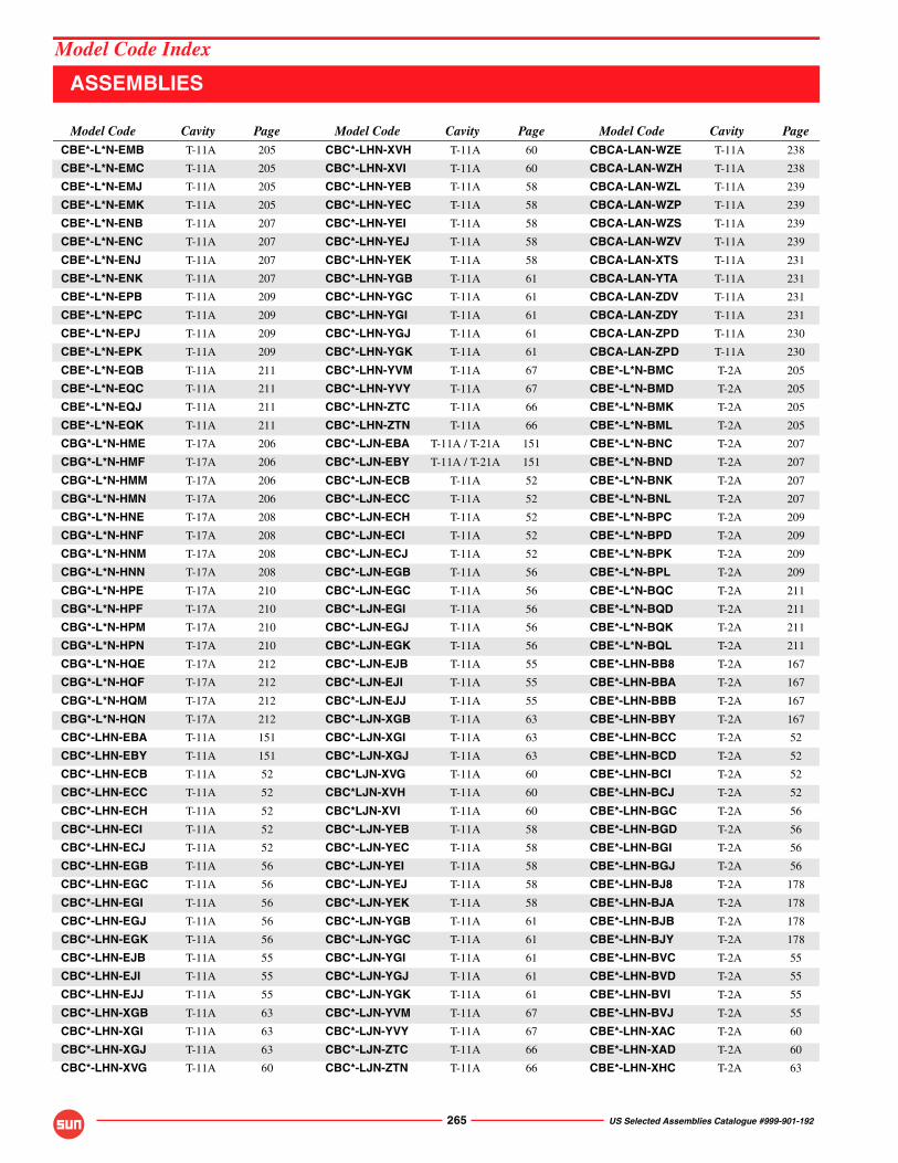
265 US Selected Assemblies Catalogue #999-901-192
CBE*-L*N-EMB T-11A 205
CBE*-L*N-EMC T-11A 205
CBE*-L*N-EMJ T-11A 205
CBE*-L*N-EMK T-11A 205
CBE*-L*N-ENB T-11A 207
CBE*-L*N-ENC T-11A 207
CBE*-L*N-ENJ T-11A 207
CBE*-L*N-ENK T-11A 207
CBE*-L*N-EPB T-11A 209
CBE*-L*N-EPC T-11A 209
CBE*-L*N-EPJ T-11A 209
CBE*-L*N-EPK T-11A 209
CBE*-L*N-EQB T-11A 211
CBE*-L*N-EQC T-11A 211
CBE*-L*N-EQJ T-11A 211
CBE*-L*N-EQK T-11A 211
CBG*-L*N-HME T-17A 206
CBG*-L*N-HMF T-17A 206
CBG*-L*N-HMM T-17A 206
CBG*-L*N-HMN T-17A 206
CBG*-L*N-HNE T-17A 208
CBG*-L*N-HNF T-17A 208
CBG*-L*N-HNM T-17A 208
CBG*-L*N-HNN T-17A 208
CBG*-L*N-HPE T-17A 210
CBG*-L*N-HPF T-17A 210
CBG*-L*N-HPM T-17A 210
CBG*-L*N-HPN T-17A 210
CBG*-L*N-HQE T-17A 212
CBG*-L*N-HQF T-17A 212
CBG*-L*N-HQM T-17A 212
CBG*-L*N-HQN T-17A 212
CBC*-LHN-EBA T-11A 151
CBC*-LHN-EBY T-11A 151
CBC*-LHN-ECB T-11A 52
CBC*-LHN-ECC T-11A 52
CBC*-LHN-ECH T-11A 52
CBC*-LHN-ECI T-11A 52
CBC*-LHN-ECJ T-11A 52
CBC*-LHN-EGB T-11A 56
CBC*-LHN-EGC T-11A 56
CBC*-LHN-EGI T-11A 56
CBC*-LHN-EGJ T-11A 56
CBC*-LHN-EGK T-11A 56
CBC*-LHN-EJB T-11A 55
CBC*-LHN-EJI T-11A 55
CBC*-LHN-EJJ T-11A 55
CBC*-LHN-XGB T-11A 63
CBC*-LHN-XGI T-11A 63
CBC*-LHN-XGJ T-11A 63
CBC*-LHN-XVG T-11A 60
CBC*-LHN-XVH T-11A 60
CBC*-LHN-XVI T-11A 60
CBC*-LHN-YEB T-11A 58
CBC*-LHN-YEC T-11A 58
CBC*-LHN-YEI T-11A 58
CBC*-LHN-YEJ T-11A 58
CBC*-LHN-YEK T-11A 58
CBC*-LHN-YGB T-11A 61
CBC*-LHN-YGC T-11A 61
CBC*-LHN-YGI T-11A 61
CBC*-LHN-YGJ T-11A 61
CBC*-LHN-YGK T-11A 61
CBC*-LHN-YVM T-11A 67
CBC*-LHN-YVY T-11A 67
CBC*-LHN-ZTC T-11A 66
CBC*-LHN-ZTN T-11A 66
CBC*-LJN-EBA T-11A / T-21A 151
CBC*-LJN-EBY T-11A / T-21A 151
CBC*-LJN-ECB T-11A 52
CBC*-LJN-ECC T-11A 52
CBC*-LJN-ECH T-11A 52
CBC*-LJN-ECI T-11A 52
CBC*-LJN-ECJ T-11A 52
CBC*-LJN-EGB T-11A 56
CBC*-LJN-EGC T-11A 56
CBC*-LJN-EGI T-11A 56
CBC*-LJN-EGJ T-11A 56
CBC*-LJN-EGK T-11A 56
CBC*-LJN-EJB T-11A 55
CBC*-LJN-EJI T-11A 55
CBC*-LJN-EJJ T-11A 55
CBC*-LJN-XGB T-11A 63
CBC*-LJN-XGI T-11A 63
CBC*-LJN-XGJ T-11A 63
CBC*LJN-XVG T-11A 60
CBC*LJN-XVH T-11A 60
CBC*LJN-XVI T-11A 60
CBC*-LJN-YEB T-11A 58
CBC*-LJN-YEC T-11A 58
CBC*-LJN-YEI T-11A 58
CBC*-LJN-YEJ T-11A 58
CBC*-LJN-YEK T-11A 58
CBC*-LJN-YGB T-11A 61
CBC*-LJN-YGC T-11A 61
CBC*-LJN-YGI T-11A 61
CBC*-LJN-YGJ T-11A 61
CBC*-LJN-YGK T-11A 61
CBC*-LJN-YVM T-11A 67
CBC*-LJN-YVY T-11A 67
CBC*-LJN-ZTC T-11A 66
CBC*-LJN-ZTN T-11A 66
CBCA-LAN-WZE T-11A 238
CBCA-LAN-WZH T-11A 238
CBCA-LAN-WZL T-11A 239
CBCA-LAN-WZP T-11A 239
CBCA-LAN-WZS T-11A 239
CBCA-LAN-WZV T-11A 239
CBCA-LAN-XTS T-11A 231
CBCA-LAN-YTA T-11A 231
CBCA-LAN-ZDV T-11A 231
CBCA-LAN-ZDY T-11A 231
CBCA-LAN-ZPD T-11A 230
CBCA-LAN-ZPD T-11A 230
CBE*-L*N-BMC T-2A 205
CBE*-L*N-BMD T-2A 205
CBE*-L*N-BMK T-2A 205
CBE*-L*N-BML T-2A 205
CBE*-L*N-BNC T-2A 207
CBE*-L*N-BND T-2A 207
CBE*-L*N-BNK T-2A 207
CBE*-L*N-BNL T-2A 207
CBE*-L*N-BPC T-2A 209
CBE*-L*N-BPD T-2A 209
CBE*-L*N-BPK T-2A 209
CBE*-L*N-BPL T-2A 209
CBE*-L*N-BQC T-2A 211
CBE*-L*N-BQD T-2A 211
CBE*-L*N-BQK T-2A 211
CBE*-L*N-BQL T-2A 211
CBE*-LHN-BB8 T-2A 167
CBE*-LHN-BBA T-2A 167
CBE*-LHN-BBB T-2A 167
CBE*-LHN-BBY T-2A 167
CBE*-LHN-BCC T-2A 52
CBE*-LHN-BCD T-2A 52
CBE*-LHN-BCI T-2A 52
CBE*-LHN-BCJ T-2A 52
CBE*-LHN-BGC T-2A 56
CBE*-LHN-BGD T-2A 56
CBE*-LHN-BGI T-2A 56
CBE*-LHN-BGJ T-2A 56
CBE*-LHN-BJ8 T-2A 178
CBE*-LHN-BJA T-2A 178
CBE*-LHN-BJB T-2A 178
CBE*-LHN-BJY T-2A 178
CBE*-LHN-BVC T-2A 55
CBE*-LHN-BVD T-2A 55
CBE*-LHN-BVI T-2A 55
CBE*-LHN-BVJ T-2A 55
CBE*-LHN-XAC T-2A 60
CBE*-LHN-XAD T-2A 60
CBE*-LHN-XHC T-2A 63
Model Code Cavity Page Model Code Cavity Page Model Code Cavity Page
ASSEMBLIES
Model Code Index
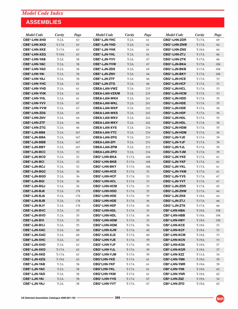
US Selected Assemblies Catalogue #999-901-192 266
CBE*-LHN-XHD T-2A 63
CBE*-LHN-XKD T-17A 63
CBE*-LHN-XKE T-17A 63
CBE*-LHN-XZQ T-19A 63
CBE*-LHN-YAB T-2A 58
CBE*-LHN-YAC T-2A 58
CBE*-LHN-YAD T-2A 58
CBE*-LHN-YAI T-2A 58
CBE*-LHN-YAJ T-2A 58
CBE*-LHN-YHC T-2A 61
CBE*-LHN-YHD T-2A 61
CBE*-LHN-YHK T-2A 61
CBE*-LHN-YHL T-2A 61
CBE*-LHN-YVV T-2A 67
CBE*-LHN-YVW T-2A 67
CBE*-LHN-ZDS T-2A 65
CBE*-LHN-ZNV T-2A 64
CBE*-LHN-ZTF T-2A 66
CBE*-LHN-ZTG T-2A 66
CBE*-LJN-BB8 T-2A 167
CBE*-LJN-BBA T-2A 167
CBE*-LJN-BBB T-2A 167
CBE*-LJN-BBY T-2A 167
CBE*-LJN-BCC T-2A 52
CBE*-LJN-BCD T-2A 52
CBE*-LJN-BCI T-2A 52
CBE*-LJN-BCJ T-2A 52
CBE*-LJN-BGC T-2A 56
CBE*-LJN-BGD T-2A 56
CBE*-LJN-BGI T-2A 56
CBE*-LJN-BGJ T-2A 56
CBE*-LJN-BJ8 T-2A 178
CBE*-LJN-BJA T-2A 178
CBE*-LJN-BJB T-2A 178
CBE*-LJN-BJY T-2A 178
CBE*-LJN-BVC T-2A 55
CBE*-LJN-BVD T-2A 55
CBE*-LJN-BVI T-2A 55
CBE*-LJN-BVJ T-2A 55
CBE*-LJN-XAC T-2A 60
CBE*-LJN-XAD T-2A 60
CBE*-LJN-XHC T-2A 63
CBE*-LJN-XHD T-2A 63
CBE*-LJN-XKD T-17A 63
CBE*-LJN-XKE T-17A 63
CBE*-LJN-XZQ T-19A 63
CBE*-LJN-YAB T-2A 58
CBE*-LJN-YAC T-2A 58
CBE*-LJN-YAD T-2A 58
CBE*-LJN-YAI T-2A 58
CBE*-LJN-YAJ T-2A 58
CBE*-LJN-YHC T-2A 61
CBE*-LJN-YHD T-2A 61
CBE*-LJN-YHK T-2A 61
CBE*-LJN-YHL T-2A 61
CBE*-LJN-YVV T-2A 67
CBE*-LJN-YVW T-2A 67
CBE*-LJN-ZDS T-2A 65
CBE*-LJN-ZNV T-2A 64
CBE*-LJN-ZTF T-2A 66
CBE*-LJN-ZTG T-2A 66
CBEA-LAN-VWZ T-2A 235
CBEA-LAN-VZX/M T-2A 235
CBEA-LAN-WKH T-2A 241
CBEA-LAN-WKL T-2A 241
CBEA-LAN-WKP T-2A 242
CBEA-LAN-WKS T-2A 242
CBEA-LAN-WKV T-2A 242
CBEA-LAN-WKY T-2A 242
CBEA-LAN-XYS T-2A 234
CBEA-LAN-YTC T-2A 234
CBEA-LAN-ZPG T-2A 233
CBEA-LAN-ZPI T-2A 233
CBEA-LAN-ZPM T-2A 233
CBEA-LAN-ZPO T-2A 234
CBG*-LHN-BKA T-17A 188
CBG*-LHN-BKB T-17A 188
CBG*-LHN-BKY T-17A 188
CBG*-LHN-HCE T-17A 53
CBG*-LHN-HCF T-17A 53
CBG*-LHN-HCL T-17A 53
CBG*-LHN-HCM T-17A 53
CBG*-LHN-HDD T-17A 55
CBG*-LHN-HDE T-17A 55
CBG*-LHN-HDE T-17A 56
CBG*-LHN-HDF T-17A 56
CBG*-LHN-HDL T-17A 55
CBG*-LHN-HDL T-17A 56
CBG*-LHN-HDM T-17A 55
CBG*-LHN-HDM T-17A 56
CBG*-LHN-XJW T-17A 60
CBG*-LHN-XJX T-17A 60
CBG*-LHN-YJE T-17A 59
CBG*-LHN-YJF T-17A 59
CBG*-LHN-YJL T-17A 59
CBG*-LHN-YJM T-17A 59
CBG*LHN-YKE T-17A 61
CBG*LHN-YKF T-17A 61
CBG*LHN-YKL T-17A 61
CBG*LHN-YKM T-17A 61
CBG*-LHN-YVS T-17A 67
CBG*-LHN-YVT T-17A 67
CBG*-LHN-ZDR T-17A 65
CBG*-LHN-ZNW T-17A 64
CBG*-LHN-ZNX T-19A 64
CBG*-LHN-ZTJ T-17A 66
CBG*-LHN-ZTK T-17A 66
CBG*-LJN-BKA T-17A 188
CBG*-LJN-BKB T-17A 188
CBG*-LJN-BKY T-17A 188
CBG*-LJN-HCE T-17A 53
CBG*-LJN-HCF T-17A 53
CBG*-LJN-HCL T-17A 53
CBG*-LJN-HCM T-17A 53
CBG*-LJN-HDD T-17A 55
CBG*-LJN-HDE T-17A 55
CBG*-LJN-HDE T-17A 56
CBG*-LJN-HDF T-17A 56
CBG*-LJN-HDL T-17A 55
CBG*-LJN-HDL T-17A 56
CBG*-LJN-HDM T-17A 55
CBG*-LJN-HDM T-17A 56
CBG*-LJN-YJE T-17A 59
CBG*-LJN-YJF T-17A 59
CBG*-LJN-YJL T-17A 59
CBG*-LJN-YJM T-17A 59
CBG*-LJN-YKE T-17A 61
CBG*-LJN-YKF T-17A 61
CBG*-LJN-YKL T-17A 61
CBG*-LJN-YKM T-17A 61
CBG*-LJN-YVS T-17A 67
CBG*-LJN-YVT T-17A 67
CBG*-LJN-ZDR T-17A 65
CBG*-LJN-ZNW T-17A 64
CBG*-LJN-ZNX T-19A 64
CBG*-LJN-ZTJ T-17A 66
CBG*-LJN-ZTK T-17A 66
CBI*-LHN-HBA T-19A 198
CBI*-LHN-HBB T-19A 198
CBI*-LHN-HBY T-19A 198
CBI*-LHN-KCE T-19A 53
CBI*-LHN-KCF T-19A 53
CBI*-LHN-KCM T-19A 53
CBI*-LHN-KCN T-19A 53
CBI*-LHN-KG6 T-19A 57
CBI*-LHN-KGR T-19A 57
CBI*-LHN-XZZ T-11A 54
CBI*-LHN-YM6 T-19A 59
CBI*-LHN-YMR T-19A 59
CBI*-LHN-YN6 T-19A 62
CBI*-LHN-YNR T-19A 62
CBI*-LHN-Z8Z T-19A 54
CBI*-LHN-ZFD T-19A 65
Model Code Cavity Page Model Code Cavity Page Model Code Cavity Page
ASSEMBLIES
Model Code Index
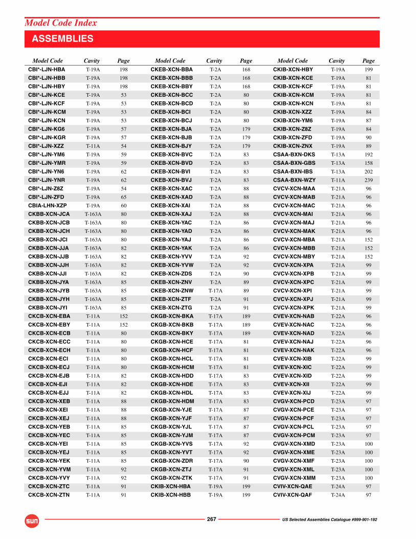
267 US Selected Assemblies Catalogue #999-901-192
CBI*-LJN-HBA T-19A 198
CBI*-LJN-HBB T-19A 198
CBI*-LJN-HBY T-19A 198
CBI*-LJN-KCE T-19A 53
CBI*-LJN-KCF T-19A 53
CBI*-LJN-KCM T-19A 53
CBI*-LJN-KCN T-19A 53
CBI*-LJN-KG6 T-19A 57
CBI*-LJN-KGR T-19A 57
CBI*-LJN-XZZ T-11A 54
CBI*-LJN-YM6 T-19A 59
CBI*-LJN-YMR T-19A 59
CBI*-LJN-YN6 T-19A 62
CBI*-LJN-YNR T-19A 62
CBI*-LJN-Z8Z T-19A 54
CBI*-LJN-ZFD T-19A 65
CBIA-LHN-XZP T-19A 60
CKBB-XCN-JCA T-163A 80
CKBB-XCN-JCB T-163A 80
CKBB-XCN-JCH T-163A 80
CKBB-XCN-JCI T-163A 80
CKBB-XCN-JJA T-163A 82
CKBB-XCN-JJB T-163A 82
CKBB-XCN-JJH T-163A 82
CKBB-XCN-JJI T-163A 82
CKBB-XCN-JYA T-163A 85
CKBB-XCN-JYB T-163A 85
CKBB-XCN-JYH T-163A 85
CKBB-XCN-JYI T-163A 85
CKCB-XCN-EBA T-11A 152
CKCB-XCN-EBY T-11A 152
CKCB-XCN-ECB T-11A 80
CKCB-XCN-ECC T-11A 80
CKCB-XCN-ECH T-11A 80
CKCB-XCN-ECI T-11A 80
CKCB-XCN-ECJ T-11A 80
CKCB-XCN-EJB T-11A 82
CKCB-XCN-EJI T-11A 82
CKCB-XCN-EJJ T-11A 82
CKCB-XCN-XEB T-11A 88
CKCB-XCN-XEI T-11A 88
CKCB-XCN-XEJ T-11A 88
CKCB-XCN-YEB T-11A 85
CKCB-XCN-YEC T-11A 85
CKCB-XCN-YEI T-11A 85
CKCB-XCN-YEJ T-11A 85
CKCB-XCN-YEK T-11A 85
CKCB-XCN-YVM T-11A 92
CKCB-XCN-YVY T-11A 92
CKCB-XCN-ZTC T-11A 91
CKCB-XCN-ZTN T-11A 91
CKEB-XCN-BBA T-2A 168
CKEB-XCN-BBB T-2A 168
CKEB-XCN-BBY T-2A 168
CKEB-XCN-BCC T-2A 80
CKEB-XCN-BCD T-2A 80
CKEB-XCN-BCI T-2A 80
CKEB-XCN-BCJ T-2A 80
CKEB-XCN-BJA T-2A 179
CKEB-XCN-BJB T-2A 179
CKEB-XCN-BJY T-2A 179
CKEB-XCN-BVC T-2A 83
CKEB-XCN-BVD T-2A 83
CKEB-XCN-BVI T-2A 83
CKEB-XCN-BVJ T-2A 83
CKEB-XCN-XAC T-2A 88
CKEB-XCN-XAD T-2A 88
CKEB-XCN-XAI T-2A 88
CKEB-XCN-XAJ T-2A 88
CKEB-XCN-YAC T-2A 86
CKEB-XCN-YAD T-2A 86
CKEB-XCN-YAJ T-2A 86
CKEB-XCN-YAK T-2A 86
CKEB-XCN-YVV T-2A 92
CKEB-XCN-YVW T-2A 92
CKEB-XCN-ZDS T-2A 90
CKEB-XCN-ZNV T-2A 89
CKEB-XCN-ZNW T-17A 89
CKEB-XCN-ZTF T-2A 91
CKEB-XCN-ZTG T-2A 91
CKGB-XCN-BKA T-17A 189
CKGB-XCN-BKB T-17A 189
CKGB-XCN-BKY T-17A 189
CKGB-XCN-HCE T-17A 81
CKGB-XCN-HCF T-17A 81
CKGB-XCN-HCL T-17A 81
CKGB-XCN-HCM T-17A 81
CKGB-XCN-HDD T-17A 83
CKGB-XCN-HDE T-17A 83
CKGB-XCN-HDL T-17A 83
CKGB-XCN-HDM T-17A 83
CKGB-XCN-YJE T-17A 87
CKGB-XCN-YJF T-17A 87
CKGB-XCN-YJL T-17A 87
CKGB-XCN-YJM T-17A 87
CKGB-XCN-YVS T-17A 92
CKGB-XCN-YVT T-17A 92
CKGB-XCN-ZDR T-17A 90
CKGB-XCN-ZTJ T-17A 91
CKGB-XCN-ZTK T-17A 91
CKIB-XCN-HBA T-19A 199
CKIB-XCN-HBB T-19A 199
CKIB-XCN-HBY T-19A 199
CKIB-XCN-KCE T-19A 81
CKIB-XCN-KCF T-19A 81
CKIB-XCN-KCM T-19A 81
CKIB-XCN-KCN T-19A 81
CKIB-XCN-XZZ T-19A 84
CKIB-XCN-YM6 T-19A 87
CKIB-XCN-Z8Z T-19A 84
CKIB-XCN-ZFD T-19A 90
CKIB-XCN-ZNX T-19A 89
CSAA-BXN-DKS T-13A 192
CSAA-BXN-GBS T-13A 158
CSAA-BXN-IBS T-13A 202
CSAA-BXN-WZY T-11A 239
CVCV-XCN-MAA T-21A 96
CVCV-XCN-MAB T-21A 96
CVCV-XCN-MAC T-21A 96
CVCV-XCN-MAI T-21A 96
CVCV-XCN-MAJ T-21A 96
CVCV-XCN-MAK T-21A 96
CVCV-XCN-MBA T-21A 152
CVCV-XCN-MBB T-21A 152
CVCV-XCN-MBY T-21A 152
CVCV-XCN-XPA T-21A 99
CVCV-XCN-XPB T-21A 99
CVCV-XCN-XPC T-21A 99
CVCV-XCN-XPI T-21A 99
CVCV-XCN-XPJ T-21A 99
CVCV-XCN-XPK T-21A 99
CVEV-XCN-NAB T-22A 96
CVEV-XCN-NAC T-22A 96
CVEV-XCN-NAD T-22A 96
CVEV-XCN-NAJ T-22A 96
CVEV-XCN-NAK T-22A 96
CVEV-XCN-XIB T-22A 99
CVEV-XCN-XIC T-22A 99
CVEV-XCN-XID T-22A 99
CVEV-XCN-XII T-22A 99
CVEV-XCN-XIJ T-22A 99
CVGV-XCN-PCD T-23A 97
CVGV-XCN-PCE T-23A 97
CVGV-XCN-PCF T-23A 97
CVGV-XCN-PCL T-23A 97
CVGV-XCN-PCM T-23A 97
CVGV-XCN-XMD T-23A 100
CVGV-XCN-XME T-23A 100
CVGV-XCN-XMF T-23A 100
CVGV-XCN-XML T-23A 100
CVGV-XCN-XMM T-23A 100
CVIV-XCN-QAE T-24A 97
CVIV-XCN-QAF T-24A 97
Model Code Cavity Page Model Code Cavity Page Model Code Cavity Page
ASSEMBLIES
Model Code Index

US Selected Assemblies Catalogue #999-901-192 268
CVIV-XCN-QAM T-24A 97
CVIV-XCN-QAN T-24A 97
CVIV-XCN-XLE T-24A 100
CVIV-XCN-XLF T-24A 100
CVIV-XCN-Z9T T-24A 98
CWC*-LGN-MAB T-21A 72
CWC*-LGN-MAC T-21A 72
CWC*-LGN-MAI T-21A 72
CWC*-LGN-MAJ T-21A 72
CWC*-LGN-MAK T-21A 72
CWC*-LGN-MBA T-21A 151
CWC*-LGN-MBB T-21A 151
CWC*-LGN-MBY T-21A 151
CWC*-LGN-XPB T-21A 75
CWC*-LGN-XPC T-21A 75
CWC*-LGN-XPI T-21A 75
CWC*-LGN-XPJ T-21A 75
CWC*-LGN-XPK T-21A 75
CWC*-LHN-MAB T-21A 72
CWC*-LHN-MAC T-21A 72
CWC*-LHN-MAI T-21A 72
CWC*-LHN-MAJ T-21A 72
CWC*-LHN-MAK T-21A 72
CWC*-LHN-MBA T-21A 151
CWC*-LHN-MBB T-21A 151
CWC*-LHN-MBY T-21A 151
CWC*-LHN-XPB T-21A 75
CWC*-LHN-XPC T-21A 75
CWC*-LHN-XPI T-21A 75
CWC*-LHN-XPJ T-21A 75
CWC*-LHN-XPK T-21A 75
CWE*-LFN-NAC T-22A 72
CWE*-LFN-NAD T-22A 72
CWE*-LFN-NAJ T-22A 72
CWE*-LFN-NAK T-22A 72
CWE*-LFN-XIC T-22A 75
CWE*-LFN-XID T-22A 75
CWE*-LFN-XII T-22A 75
CWE*-LFN-XIJ T-22A 75
CWE*-LHN-NAC T-22A 72
CWE*-LHN-NAD T-22A 72
CWE*-LHN-NAJ T-22A 72
CWE*-LHN-NAK T-22A 72
CWE*-LHN-XIC T-22A 75
CWE*-LHN-XID T-22A 75
CWE*-LHN-XIE T-22A 75
CWE*-LHN-XII T-22A 75
CWE*-LHN-XIJ T-22A 75
CWG*-LGN-PAE T-23A 73
CWG*-LGN-PAF T-23A 73
CWG*-LGN-PAL T-23A 73
CWG*-LGN-PAM T-23A 73
CWG*-LGN-XME T-23A 76
CWG*-LGN-XMF T-23A 76
CWG*-LGN-XML T-23A 76
CWG*-LGN-XMM T-23A 76
CWG*-LHN-PAE T-23A 73
CWG*-LHN-PAF T-23A 73
CWG*-LHN-PAL T-23A 73
CWG*-LHN-PAM T-23A 73
CWG*-LHN-XME T-23A 76
CWG*-LHN-XMF T-23A 76
CWG*-LHN-XML T-23A 76
CWG*-LHN-XMM T-23A 76
CWI*- LHN-XLE T-24A 76
CWI*- LHN-XLF T-24A 76
CWI*-LFN-QCE T-24A 73
CWI*-LFN-QCF T-24A 73
CWI*-LFN-QCM T-24A 73
CWI*-LFN-QCN T-24A 73
CWI*-LFN-XLE T-24A 76
CWI*-LFN-XLF T-24A 76
CWI*-LFN-Z9T T-24A 74
CWI*-LHN-QCE T-24A 73
CWI*-LHN-QCF T-24A 73
CWI*-LHN-QCM T-24A 73
CWI*-LHN-QCN T-24A 73
CWI*-LHN-Z9T T-24A 74
CXAD-X*N-AAA T-162A 104
CXAD-X*N-AAB T-162A 104
CXAD-X*N-AAH T-162A 104
CXAD-X*N-AAI T-162A 104
CXAD-X*N-ACA T-162A 106
CXAD-X*N-ACB T-162A 106
CXAD-X*N-ACH T-162A 106
CXAD-X*N-ACI T-162A 106
CXBA-X*N-AAA T-162A 104
CXBA-X*N-AAB T-162A 104
CXBA-X*N-AAH T-162A 104
CXBA-X*N-AAI T-162A 104
CXBA-X*N-ACA T-162A 106
CXBA-X*N-ACB T-162A 106
CXBA-X*N-ACH T-162A 106
CXBA-X*N-ACI T-162A 106
CXCD-X*N-GAA T-13A 104
CXCD-X*N-GAB T-13A 104
CXCD-X*N-GAH T-13A 104
CXCD-X*N-GAI T-13A 104
CXCD-X*N-GAJ T-13A 104
CXCD-X*N-GCA T-13A 106
CXCD-X*N-GCB T-13A 106
CXCD-X*N-GCI T-13A 106
CXCD-X*N-GCJ T-13A 106
CXDA-X*N-GAA T-13A 104
CXDA-X*N-GAB T-13A 104
CXDA-X*N-GAH T-13A 104
CXDA-X*N-GAI T-13A 104
CXDA-X*N-GAJ T-13A 104
CXDA-X*N-GCA T-13A 106
CXDA-X*N-GCB T-13A 106
CXDA-X*N-GCI T-13A 106
CXDA-X*N-GCJ T-13A 106
CXDA-X*N-GDA T-13A / T-5A 153
CXDA-X*N-GDP T-13A / T-5A 153
CXDA-X*N-GDW T-13A / T-5A 153
CXDA-X*N-GDY T-13A / T-5A 153
CXED-X*N-DAB T-5A 104
CXED-X*N-DAC T-5A 104
CXED-X*N-DAJ T-5A 104
CXED-X*N-DAK T-5A 104
CXED-X*N-DCB T-5A 106
CXED-X*N-DCC T-5A 106
CXED-X*N-DCI T-5A 106
CXED-X*N-DCJ T-5A 106
CXED-X*N-DCK T-5A 106
CXFA-X*N-DAB T-5A 104
CXFA-X*N-DAC T-5A 104
CXFA-X*N-DAJ T-5A 104
CXFA-X*N-DAK T-5A 104
CXFA-X*N-DCB T-5A 106
CXFA-X*N-DCC T-5A 106
CXFA-X*N-DCI T-5A 106
CXFA-X*N-DCJ T-5A 106
CXFA-X*N-DCK T-5A 06
CXFA-X*N-GDF T-13A 153
CXFA-XAN-DBW T-5A 169
CXFA-XAN-DJW T-5A 180
CXFA-XCN-DBJ T-5A 169
CXFA-XCN-DBK T-5A 169
CXFA-XCN-DBP T-5A 169
CXFA-XCN-DJJ T-5A 180
CXFA-XCN-DJK T-5A 180
CXFA-XCN-DJP T-5A 180
CXGD-X*N-IAD T-16A 105
CXGD-X*N-IAE T-16A 105
CXGD-X*N-IAF T-16A 105
CXGD-X*N-IAL T-16A 105
CXGD-X*N-IAM T-16A 105
CXGD-X*N-ICD T-16A 107
CXGD-X*N-ICE T-16A 107
CXGD-X*N-ICF T-16A 107
CXGD-X*N-ICL T-16A 107
CXGD-X*N-ICM T-16A 107
Model Code Cavity Page Model Code Cavity Page Model Code Cavity Page
ASSEMBLIES
Model Code Index
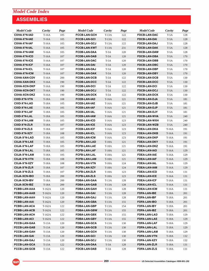
269 US Selected Assemblies Catalogue #999-901-192
CXHA-X*N-IAD T-16A 105
CXHA-X*N-IAE T-16A 105
CXHA-X*N-IAF T-16A 105
CXHA-X*N-IAL T-16A 105
CXHA-X*N-IAM T-16A 105
CXHA-X*N-ICD T-16A 107
CXHA-X*N-ICE T-16A 107
CXHA-X*N-ICF T-16A 107
CXHA-X*N-ICL T-16A 107
CXHA-X*N-ICM T-16A 107
CXHA-XAN-CDV T-16A 200
CXHA-XAN-DKX T-16A 190
CXHA-XCN-DKP T-16A 190
CXHA-XCN-DKT T-16A 190
CXHA-XCN-DKZ T-16A 190
CXID-X*N-VTN T-18A 108
CXID-X*N-LAD T-18A 105
CXID-X*N-LAE T-18A 105
CXID-X*N-LAF T-18A 105
CXID-X*N-LAL T-18A 105
CXID-X*N-LAM T-18A 105
CXID-X*N-ZLR T-18A 107
CXID-X*N-ZLS T-18A 107
CXID-X*N-XZY T-18A 108
CXJA-X*N-LAD T-18A 105
CXJA-X*N-LAE T-18A 105
CXJA-X*N-LAF T-18A 105
CXJA-X*N-LAL T-18A 105
CXJA-X*N-LAM T-18A 105
CXJA-X*N-VTN T-18A 108
CXJA-X*N-XZY T-18A 108
CXJA-X*N-ZLR T-18A 107
CXJA-X*N-ZLS T-18A 107
CXJA-XCN-IBO T-18A 200
CXJA-XCN-IBV T-18A 200
CXJA-XCN-IBZ T-18A 200
FCBB-LAN-AAA T-162A 120
FCBB-LAN-AAB T-162A 120
FCBB-LAN-AAH T-162A 120
FCBB-LAN-AAI T-162A 120
FCBB-LAN-ACA T-162A 122
FCBB-LAN-ACB T-162A 122
FCBB-LAN-ACH T-162A 122
FCBB-LAN-ACI T-162A 122
FCCB-LAN-GAA T-13A 120
FCCB-LAN-GAB T-13A 120
FCCB-LAN-GAH T-13A 120
FCCB-LAN-GAI T-13A 120
FCCB-LAN-GAJ T-13A 120
FCCB-LAN-GCA T-13A 122
FCCB-LAN-GCB T-13A 122
FCCB-LAN-GCH T-13A 122
FCCB-LAN-GCI T-13A 122
FCCB-LAN-GCJ T-13A 122
FCCB-LAN-XWT T-13A 231
FCDB-LAN-DAA T-5A 120
FCDB-LAN-DAB T-5A 120
FCDB-LAN-DAC T-5A 120
FCDB-LAN-DAI T-5A 120
FCDB-LAN-DAJ T-5A 120
FCDB-LAN-DAK T-5A 120
FCDB-LAN-DCB T-5A 122
FCDB-LAN-DCC T-5A 122
FCDB-LAN-DCI T-5A 122
FCDB-LAN-DCJ T-5A 122
FCDB-LAN-DCK T-5A 122
FCEB-LAN-IAD T-16A 121
FCEB-LAN-IAE T-16A 121
FCEB-LAN-IAF T-16A 121
FCEB-LAN-IAL T-16A 121
FCEB-LAN-IAM T-16A 121
FCEB-LAN-ICD T-16A 123
FCEB-LAN-ICE T-16A 123
FCEB-LAN-ICF T-16A 123
FCEB-LAN-ICL T-16A 123
FCEB-LAN-ICM T-16A 123
FCFB-LAN-LAD T-18A 121
FCFB-LAN-LAE T-18A 121
FCFB-LAN-LAF T-18A 121
FCFB-LAN-LAL T-18A 121
FCFB-LAN-LAM T-18A 121
FCFB-LAN-VTN T-18A 124
FCFB-LAN-XZY T-18A 124
FCFB-LAN-ZLR T-18A 123
FCFB-LAN-ZLS T-18A 123
FDBA-LAN-GAA T-13A 128
FDBA-LAN-GAB T-13A 128
FDBA-LAN-GAH T-13A 128
FDBA-LAN-GAI T-13A 128
FDBA-LAN-GAJ T-13A 128
FDBA-LAN-GBA T-13A 155
FDBA-LAN-GBP T-13A 154
FDBA-LAN-GBW T-13A 155
FDBA-LAN-GBX T-13A 155
FDBA-LAN-GBY T-13A 155
FDBA-LAN-GCA T-13A 130
FDBA-LAN-GCB T-13A 130
FDBA-LAN-GCH T-13A 130
FDBA-LAN-GCI T-13A 130
FDBA-LAN-GCJ T-13A 130
FDCB-LAN-DAA T-5A 128
FDCB-LAN-DAB T-5A 128
FDCB-LAN-DAC T-5A 128
FDCB-LAN-DAI T-5A 128
FDCB-LAN-DAJ T-5A 128
FDCB-LAN-DAK T-5A 128
FDCB-LAN-DAW T-5A 128
FDCB-LAN-DBA T-5A 170
FDCB-LAN-DBB T-5A 170
FDCB-LAN-DBC T-5A 170
FDCB-LAN-DBP T-5A 170
FDCB-LAN-DBY T-5A 170
FDCB-LAN-DCB T-5A 130
FDCB-LAN-DCC T-5A 130
FDCB-LAN-DCI T-5A 130
FDCB-LAN-DCJ T-5A 130
FDCB-LAN-DCK T-5A 130
FDCB-LAN-DJA T-5A 181
FDCB-LAN-DJB T-5A 181
FDCB-LAN-DJP T-5A 181
FDCB-LAN-DJY T-5A 181
FDCB-LAN-WVA T-5A 240
FDCB-LAN-WXH T-5A 240
FDCB-LAN-WZB T-5A 240
FDEA-LAN-DKA T-16A 191
FDEA-LAN-DKB T-16A 191
FDEA-LAN-DKP T-16A 191
FDEA-LAN-DKY T-16A 191
FDEA-LAN-DKZ T-16A 191
FDEA-LAN-IAD T-16A 129
FDEA-LAN-IAE T-16A 129
FDEA-LAN-IAF T-16A 129
FDEA-LAN-IAL T-16A 129
FDEA-LAN-IAM T-16A 129
FDEA-LAN-ICD T-16A 131
FDEA-LAN-ICE T-16A 131
FDEA-LAN-ICF T-16A 131
FDEA-LAN-ICL T-16A 131
FDEA-LAN-ICM T-16A 131
FDFA-LAN-IBE T-18A 201
FDFA-LAN-IBF T-18A 201
FDFA-LAN-IBO T-18A 201
FDFA-LAN-IBY T-18A 201
FDFA-LAN-IBZ T-18A 201
FDFA-LAN-LAD T-18A 129
FDFA-LAN-LAE T-18A 129
FDFA-LAN-LAF T-18A 129
FDFA-LAN-LAL T-18A 129
FDFA-LAN-LAM T-18A 129
FDFA-LAN-VTN T-18A 132
FDFA-LAN-XZY T-18A 132
FDFA-LAN-ZLR T-18A 131
FDFA-LAN-ZLS T-18A 131
Model Code Cavity Page Model Code Cavity Page Model Code Cavity Page
ASSEMBLIES
Model Code Index
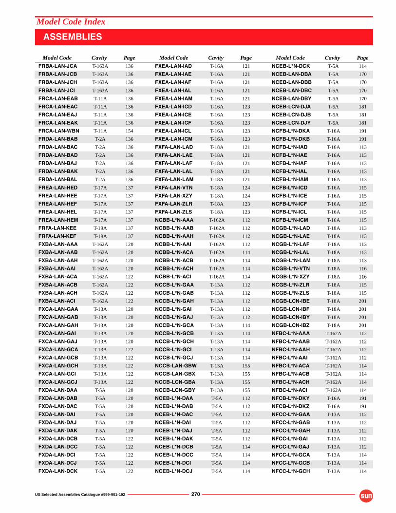
US Selected Assemblies Catalogue #999-901-192 270
FRBA-LAN-JCA T-163A 136
FRBA-LAN-JCB T-163A 136
FRBA-LAN-JCH T-163A 136
FRBA-LAN-JCI T-163A 136
FRCA-LAN-EAB T-11A 136
FRCA-LAN-EAC T-11A 136
FRCA-LAN-EAJ T-11A 136
FRCA-LAN-EAK T-11A 136
FRCA-LAN-WBN T-11A 154
FRDA-LAN-BAB T-2A 136
FRDA-LAN-BAC T-2A 136
FRDA-LAN-BAD T-2A 136
FRDA-LAN-BAJ T-2A 136
FRDA-LAN-BAK T-2A 136
FRDA-LAN-BAL T-2A 136
FREA-LAN-HED T-17A 137
FREA-LAN-HEE T-17A 137
FREA-LAN-HEF T-17A 137
FREA-LAN-HEL T-17A 137
FREA-LAN-HEM T-17A 137
FRFA-LAN-KEE T-19A 137
FRFA-LAN-KEF T-19A 137
FXBA-LAN-AAA T-162A 120
FXBA-LAN-AAB T-162A 120
FXBA-LAN-AAH T-162A 120
FXBA-LAN-AAI T-162A 120
FXBA-LAN-ACA T-162A 122
FXBA-LAN-ACB T-162A 122
FXBA-LAN-ACH T-162A 122
FXBA-LAN-ACI T-162A 122
FXCA-LAN-GAA T-13A 120
FXCA-LAN-GAB T-13A 120
FXCA-LAN-GAH T-13A 120
FXCA-LAN-GAI T-13A 120
FXCA-LAN-GAJ T-13A 120
FXCA-LAN-GCA T-13A 122
FXCA-LAN-GCB T-13A 122
FXCA-LAN-GCH T-13A 122
FXCA-LAN-GCI T-13A 122
FXCA-LAN-GCJ T-13A 122
FXDA-LAN-DAA T-5A 120
FXDA-LAN-DAB T-5A 120
FXDA-LAN-DAC T-5A 120
FXDA-LAN-DAI T-5A 120
FXDA-LAN-DAJ T-5A 120
FXDA-LAN-DAK T-5A 120
FXDA-LAN-DCB T-5A 122
FXDA-LAN-DCC T-5A 122
FXDA-LAN-DCI T-5A 122
FXDA-LAN-DCJ T-5A 122
FXDA-LAN-DCK T-5A 122
FXEA-LAN-IAD T-16A 121
FXEA-LAN-IAE T-16A 121
FXEA-LAN-IAF T-16A 121
FXEA-LAN-IAL T-16A 121
FXEA-LAN-IAM T-16A 121
FXEA-LAN-ICD T-16A 123
FXEA-LAN-ICE T-16A 123
FXEA-LAN-ICF T-16A 123
FXEA-LAN-ICL T-16A 123
FXEA-LAN-ICM T-16A 123
FXFA-LAN-LAD T-18A 121
FXFA-LAN-LAE T-18A 121
FXFA-LAN-LAF T-18A 121
FXFA-LAN-LAL T-18A 121
FXFA-LAN-LAM T-18A 121
FXFA-LAN-VTN T-18A 124
FXFA-LAN-XZY T-18A 124
FXFA-LAN-ZLR T-18A 123
FXFA-LAN-ZLS T-18A 123
NCBB-L*N-AAA T-162A 112
NCBB-L*N-AAB T-162A 112
NCBB-L*N-AAH T-162A 112
NCBB-L*N-AAI T-162A 112
NCBB-L*N-ACA T-162A 114
NCBB-L*N-ACB T-162A 114
NCBB-L*N-ACH T-162A 114
NCBB-L*N-ACI T-162A 114
NCCB-L*N-GAA T-13A 112
NCCB-L*N-GAB T-13A 112
NCCB-L*N-GAH T-13A 112
NCCB-L*N-GAI T-13A 112
NCCB-L*N-GAJ T-13A 112
NCCB-L*N-GCA T-13A 114
NCCB-L*N-GCB T-13A 114
NCCB-L*N-GCH T-13A 114
NCCB-L*N-GCI T-13A 114
NCCB-L*N-GCJ T-13A 114
NCCB-LAN-GBW T-13A 155
NCCB-LAN-GBX T-13A 155
NCCB-LCN-GBA T-13A 155
NCCB-LCN-GBY T-13A 155
NCEB-L*N-DAA T-5A 112
NCEB-L*N-DAB T-5A 112
NCEB-L*N-DAC T-5A 112
NCEB-L*N-DAI T-5A 112
NCEB-L*N-DAJ T-5A 112
NCEB-L*N-DAK T-5A 112
NCEB-L*N-DCB T-5A 114
NCEB-L*N-DCC T-5A 114
NCEB-L*N-DCI T-5A 114
NCEB-L*N-DCJ T-5A 114
NCEB-L*N-DCK T-5A 114
NCEB-LAN-DBA T-5A 170
NCEB-LAN-DBB T-5A 170
NCEB-LAN-DBC T-5A 170
NCEB-LAN-DBY T-5A 170
NCEB-LCN-DJA T-5A 181
NCEB-LCN-DJB T-5A 181
NCEB-LCN-DJY T-5A 181
NCFB-L*N-DKA T-16A 191
NCFB-L*N-DKB T-16A 191
NCFB-L*N-IAD T-16A 113
NCFB-L*N-IAE T-16A 113
NCFB-L*N-IAF T-16A 113
NCFB-L*N-IAL T-16A 113
NCFB-L*N-IAM T-16A 113
NCFB-L*N-ICD T-16A 115
NCFB-L*N-ICE T-16A 115
NCFB-L*N-ICF T-16A 115
NCFB-L*N-ICL T-16A 115
NCFB-L*N-ICM T-16A 115
NCGB-L*N-LAD T-18A 113
NCGB-L*N-LAE T-18A 113
NCGB-L*N-LAF T-18A 113
NCGB-L*N-LAL T-18A 113
NCGB-L*N-LAM T-18A 113
NCGB-L*N-VTN T-18A 116
NCGB-L*N-XZY T-18A 116
NCGB-L*N-ZLR T-18A 115
NCGB-L*N-ZLS T-18A 115
NCGB-LCN-IBE T-18A 201
NCGB-LCN-IBF T-18A 201
NCGB-LCN-IBY T-18A 201
NCGB-LCN-IBZ T-18A 201
NFBC-L*N-AAA T-162A 112
NFBC-L*N-AAB T-162A 112
NFBC-L*N-AAH T-162A 112
NFBC-L*N-AAI T-162A 112
NFBC-L*N-ACA T-162A 114
NFBC-L*N-ACB T-162A 114
NFBC-L*N-ACH T-162A 114
NFBC-L*N-ACI T-162A 114
NFCB-L*N-DKY T-16A 191
NFCB-L*N-DKZ T-16A 191
NFCC-L*N-GAA T-13A 112
NFCC-L*N-GAB T-13A 112
NFCC-L*N-GAH T-13A 112
NFCC-L*N-GAI T-13A 112
NFCC-L*N-GAJ T-13A 112
NFCC-L*N-GCA T-13A 114
NFCC-L*N-GCB T-13A 114
NFCC-L*N-GCH T-13A 114
Model Code Cavity Page Model Code Cavity Page Model Code Cavity Page
ASSEMBLIES
Model Code Index
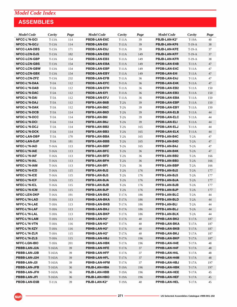
271 US Selected Assemblies Catalogue #999-901-192
NFCC-L*N-GCI T-13A 114
NFCC-L*N-GCJ T-13A 114
NFCC-LAN-DBS T-13A 171
NFCC-LCN-DJS T-13A 182
NFCC-LCN-GBP T-13A 154
NFCC-LCN-GBS T-13A 154
NFCC-LCN-GBW T-13A 154
NFCC-LCN-GBX T-13A 154
NFCC-LCN-ZFZ T-13A 232
NFDC-L*N-DAA T-5A 112
NFDC-L*N-DAB T-5A 112
NFDC-L*N-DAC T-5A 112
NFDC-L*N-DAI T-5A 112
NFDC-L*N-DAJ T-5A 112
NFDC-L*N-DAK T-5A 112
NFDC-L*N-DCB T-5A 114
NFDC-L*N-DCC T-5A 114
NFDC-L*N-DCI T-5A 114
NFDC-L*N-DCJ T-5A 114
NFDC-L*N-DCK T-5A 114
NFDC-LAN-DBP T-5A 170
NFDC-LAN-DJP T-5A 181
NFEC-L*N-IAD T-16A 113
NFEC-L*N-IAE T-16A 113
NFEC-L*N-IAF T-16A 113
NFEC-L*N-IAL T-16A 113
NFEC-L*N-IAM T-16A 113
NFEC-L*N-ICD T-16A 115
NFEC-L*N-ICE T-16A 115
NFEC-L*N-ICF T-16A 115
NFEC-L*N-ICL T-16A 115
NFEC-L*N-ICM T-16A 115
NFEC-LEN-DKP T-16A 191
NFFC-L*N-LAD T-18A 113
NFFC-L*N-LAE T-18A 113
NFFC-L*N-LAF T-18A 113
NFFC-L*N-LAL T-18A 113
NFFC-L*N-LAM T-18A 113
NFFC-L*N-VTN T-18A 116
NFFC-L*N-XZY T-18A 116
NFFC-L*N-ZLR T-18A 115
NFFC-L*N-ZLS T-18A 115
NFFC-LGN-IBO T-18A 201
PBBB-LAN-J2A T-163A 39
PBBB-LAN-J2B T-163A 39
PBBB-LAN-J2H T-163A 39
PBBB-LAN-J2I T-163A 39
PBBB-LAN-JFB T-163A 36
PBBB-LAN-JFH T-163A 36
PBBB-LAN-JFI T-163A 36
PBDB-LAN-E6B T-11A 39
PBDB-LAN-E6C T-11A 39
PBDB-LAN-E6I T-11A 39
PBDB-LAN-E6J T-11A 39
PBDB-LAN-EB2 T-11A 149
PBDB-LAN-EB3 T-11A 149
PBDB-LAN-EBA T-11A 149
PBDB-LAN-EBP T-11A 149
PBDB-LAN-EBY T-11A 149
PBDB-LAN-EFB T-11A 36
PBDB-LAN-EFC T-11A 36
PBDB-LAN-EFH T-11A 36
PBDB-LAN-EFI T-11A 36
PBDB-LAN-EFJ T-11A 36
PBFB-LAN-B6B T-2A 39
PBFB-LAN-B6C T-2A 39
PBFB-LAN-B6D T-2A 39
PBFB-LAN-B6I T-2A 39
PBFB-LAN-B6J T-2A 39
PBFB-LAN-BB2 T-2A 165
PBFB-LAN-BB3 T-2A 165
PBFB-LAN-BBA T-2A 165
PBFB-LAN-BBB T-2A 165
PBFB-LAN-BBP T-2A 165
PBFB-LAN-BFC T-2A 36
PBFB-LAN-BFD T-2A 36
PBFB-LAN-BFH T-2A 36
PBFB-LAN-BFI T-2A 36
PBFB-LAN-BJ2 T-2A 176
PBFB-LAN-BJ3 T-2A 176
PBFB-LAN-BJA T-2A 176
PBFB-LAN-BJB T-2A 176
PBFB-LAN-BJP T-2A 176
PBHB-LAN-BK2 T-17A 186
PBHB-LAN-BKA T-17A 186
PBHB-LAN-BKB T-17A 186
PBHB-LAN-BKJ T-17A 186
PBHB-LAN-BKP T-17A 186
PBHB-LAN-H2* T-17A 40
PBHB-LAN-H2* T-17A 40
PBHB-LAN-H2* T-17A 40
PBHB-LAN-H2* T-17A 40
PBHB-LAN-HBJ T-17A 196
PBHB-LAN-HBK T-17A 196
PBHB-LAN-HFE T-17A 37
PBHB-LAN-HFF T-17A 37
PBHB-LAN-HFL T-17A 37
PBHB-LAN-HFM T-17A 37
PBJB-LAN-HBA T-19A 196
PBJB-LAN-HBB T-19A 196
PBJB-LAN-HBO T-19A 196
PBJB-LAN-K2* T-19A 40
PBJB-LAN-K2* T-19A 40
PBJB-LAN-KF6 T-19-A 38
PBJB-LAN-KFE T-19-A 37
PBJB-LAN-KFF T-19-A 37
PBJB-LAN-KFR T-19-A 38
PPDB-LAN-E4B T-11A 47
PPDB-LAN-E4C T-11A 47
PPDB-LAN-E4I T-11A 47
PPDB-LAN-E4J T-11A 47
PPDB-LAN-E4K T-11A 47
PPDB-LAN-EB2 T-11A 150
PPDB-LAN-EB3 T-11A 150
PPDB-LAN-EBA T-11A 150
PPDB-LAN-EBP T-11A 150
PPDB-LAN-EBY T-11A 150
PPDB-LAN-ELB T-11A 44
PPDB-LAN-ELC T-11A 44
PPDB-LAN-ELI T-11A 44
PPDB-LAN-ELJ T-11A 44
PPDB-LAN-ELK T-11A 44
PPFB-LAN-B4C T-2A 47
PPFB-LAN-B4D T-2A 47
PPFB-LAN-B4J T-2A 47
PPFB-LAN-B4K T-2A 47
PPFB-LAN-BB2 T-2A 166
PPFB-LAN-BB3 T-2A 166
PPFB-LAN-BBP T-2A 166
PPFB-LAN-BJ2 T-2A 177
PPFB-LAN-BJ3 T-2A 177
PPFB-LAN-BJA T-2A 177
PPFB-LAN-BJB T-2A 177
PPFB-LAN-BJP T-2A 177
PPFB-LAN-BLC T-2A 44
PPFB-LAN-BLD T-2A 44
PPFB-LAN-BLI T-2A 44
PPFB-LAN-BLJ T-2A 44
PPFB-LAN-BLK T-2A 44
PPHB-LAN-BK2 T-17A 187
PPHB-LAN-BKA T-17A 187
PPHB-LAN-BKB T-17A 187
PPHB-LAN-BKJ T-17A 187
PPHB-LAN-BKP T-17A 187
PPHB-LAN-H4E T-17A 48
PPHB-LAN-H4F T-17A 48
PPHB-LAN-H4L T-17A 48
PPHB-LAN-H4M T-17A 48
PPHB-LAN-HBJ T-17A 197
PPHB-LAN-HBK T-17A 197
PPHB-LAN-HEE T-17A 45
PPHB-LAN-HEF T-17A 45
PPHB-LAN-HEL T-17A 45
Model Code Cavity Page Model Code Cavity Page Model Code Cavity Page
ASSEMBLIES
Model Code Index
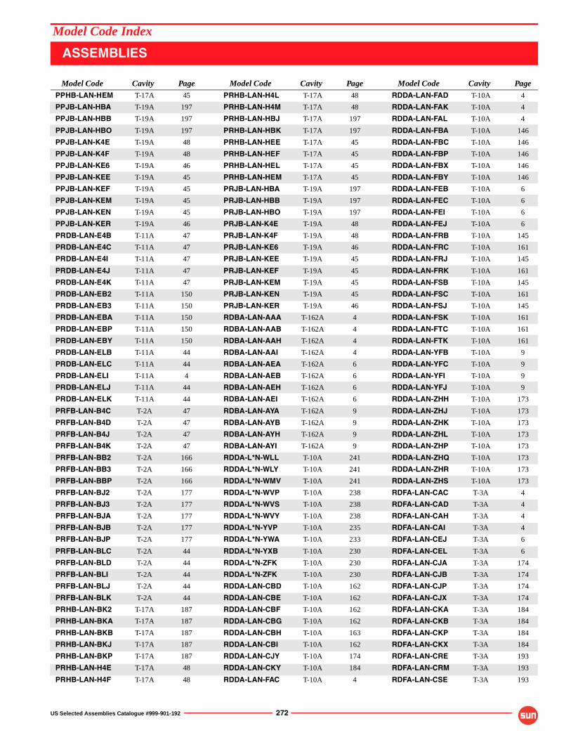
US Selected Assemblies Catalogue #999-901-192 272
PPHB-LAN-HEM T-17A 45
PPJB-LAN-HBA T-19A 197
PPJB-LAN-HBB T-19A 197
PPJB-LAN-HBO T-19A 197
PPJB-LAN-K4E T-19A 48
PPJB-LAN-K4F T-19A 48
PPJB-LAN-KE6 T-19A 46
PPJB-LAN-KEE T-19A 45
PPJB-LAN-KEF T-19A 45
PPJB-LAN-KEM T-19A 45
PPJB-LAN-KEN T-19A 45
PPJB-LAN-KER T-19A 46
PRDB-LAN-E4B T-11A 47
PRDB-LAN-E4C T-11A 47
PRDB-LAN-E4I T-11A 47
PRDB-LAN-E4J T-11A 47
PRDB-LAN-E4K T-11A 47
PRDB-LAN-EB2 T-11A 150
PRDB-LAN-EB3 T-11A 150
PRDB-LAN-EBA T-11A 150
PRDB-LAN-EBP T-11A 150
PRDB-LAN-EBY T-11A 150
PRDB-LAN-ELB T-11A 44
PRDB-LAN-ELC T-11A 44
PRDB-LAN-ELI T-11A 4
PRDB-LAN-ELJ T-11A 44
PRDB-LAN-ELK T-11A 44
PRFB-LAN-B4C T-2A 47
PRFB-LAN-B4D T-2A 47
PRFB-LAN-B4J T-2A 47
PRFB-LAN-B4K T-2A 47
PRFB-LAN-BB2 T-2A 166
PRFB-LAN-BB3 T-2A 166
PRFB-LAN-BBP T-2A 166
PRFB-LAN-BJ2 T-2A 177
PRFB-LAN-BJ3 T-2A 177
PRFB-LAN-BJA T-2A 177
PRFB-LAN-BJB T-2A 177
PRFB-LAN-BJP T-2A 177
PRFB-LAN-BLC T-2A 44
PRFB-LAN-BLD T-2A 44
PRFB-LAN-BLI T-2A 44
PRFB-LAN-BLJ T-2A 44
PRFB-LAN-BLK T-2A 44
PRHB-LAN-BK2 T-17A 187
PRHB-LAN-BKA T-17A 187
PRHB-LAN-BKB T-17A 187
PRHB-LAN-BKJ T-17A 187
PRHB-LAN-BKP T-17A 187
PRHB-LAN-H4E T-17A 48
PRHB-LAN-H4F T-17A 48
PRHB-LAN-H4L T-17A 48
PRHB-LAN-H4M T-17A 48
PRHB-LAN-HBJ T-17A 197
PRHB-LAN-HBK T-17A 197
PRHB-LAN-HEE T-17A 45
PRHB-LAN-HEF T-17A 45
PRHB-LAN-HEL T-17A 45
PRHB-LAN-HEM T-17A 45
PRJB-LAN-HBA T-19A 197
PRJB-LAN-HBB T-19A 197
PRJB-LAN-HBO T-19A 197
PRJB-LAN-K4E T-19A 48
PRJB-LAN-K4F T-19A 48
PRJB-LAN-KE6 T-19A 46
PRJB-LAN-KEE T-19A 45
PRJB-LAN-KEF T-19A 45
PRJB-LAN-KEM T-19A 45
PRJB-LAN-KEN T-19A 45
PRJB-LAN-KER T-19A 46
RDBA-LAN-AAA T-162A 4
RDBA-LAN-AAB T-162A 4
RDBA-LAN-AAH T-162A 4
RDBA-LAN-AAI T-162A 4
RDBA-LAN-AEA T-162A 6
RDBA-LAN-AEB T-162A 6
RDBA-LAN-AEH T-162A 6
RDBA-LAN-AEI T-162A 6
RDBA-LAN-AYA T-162A 9
RDBA-LAN-AYB T-162A 9
RDBA-LAN-AYH T-162A 9
RDBA-LAN-AYI T-162A 9
RDDA-L*N-WLL T-10A 241
RDDA-L*N-WLY T-10A 241
RDDA-L*N-WMV T-10A 241
RDDA-L*N-WVP T-10A 238
RDDA-L*N-WVS T-10A 238
RDDA-L*N-WVY T-10A 238
RDDA-L*N-YVP T-10A 235
RDDA-L*N-YWA T-10A 233
RDDA-L*N-YXB T-10A 230
RDDA-L*N-ZFK T-10A 230
RDDA-L*N-ZFK T-10A 230
RDDA-LAN-CBD T-10A 162
RDDA-LAN-CBE T-10A 162
RDDA-LAN-CBF T-10A 162
RDDA-LAN-CBG T-10A 162
RDDA-LAN-CBH T-10A 163
RDDA-LAN-CBI T-10A 162
RDDA-LAN-CJY T-10A 174
RDDA-LAN-CKY T-10A 184
RDDA-LAN-FAC T-10A 4
RDDA-LAN-FAD T-10A 4
RDDA-LAN-FAK T-10A 4
RDDA-LAN-FAL T-10A 4
RDDA-LAN-FBA T-10A 146
RDDA-LAN-FBC T-10A 146
RDDA-LAN-FBP T-10A 146
RDDA-LAN-FBX T-10A 146
RDDA-LAN-FBY T-10A 146
RDDA-LAN-FEB T-10A 6
RDDA-LAN-FEC T-10A 6
RDDA-LAN-FEI T-10A 6
RDDA-LAN-FEJ T-10A 6
RDDA-LAN-FRB T-10A 145
RDDA-LAN-FRC T-10A 161
RDDA-LAN-FRJ T-10A 145
RDDA-LAN-FRK T-10A 161
RDDA-LAN-FSB T-10A 145
RDDA-LAN-FSC T-10A 161
RDDA-LAN-FSJ T-10A 145
RDDA-LAN-FSK T-10A 161
RDDA-LAN-FTC T-10A 161
RDDA-LAN-FTK T-10A 161
RDDA-LAN-YFB T-10A 9
RDDA-LAN-YFC T-10A 9
RDDA-LAN-YFI T-10A 9
RDDA-LAN-YFJ T-10A 9
RDDA-LAN-ZHH T-10A 173
RDDA-LAN-ZHJ T-10A 173
RDDA-LAN-ZHK T-10A 173
RDDA-LAN-ZHL T-10A 173
RDDA-LAN-ZHP T-10A 173
RDDA-LAN-ZHQ T-10A 173
RDDA-LAN-ZHR T-10A 173
RDDA-LAN-ZHS T-10A 173
RDFA-LAN-CAC T-3A 4
RDFA-LAN-CAD T-3A 4
RDFA-LAN-CAH T-3A 4
RDFA-LAN-CAI T-3A 4
RDFA-LAN-CEJ T-3A 6
RDFA-LAN-CEL T-3A 6
RDFA-LAN-CJA T-3A 174
RDFA-LAN-CJB T-3A 174
RDFA-LAN-CJP T-3A 174
RDFA-LAN-CJX T-3A 174
RDFA-LAN-CKA T-3A 184
RDFA-LAN-CKB T-3A 184
RDFA-LAN-CKP T-3A 184
RDFA-LAN-CKX T-3A 184
RDFA-LAN-CRE T-3A 193
RDFA-LAN-CRM T-3A 193
RDFA-LAN-CSE T-3A 193
Model Code Cavity Page Model Code Cavity Page Model Code Cavity Page
ASSEMBLIES
Model Code Index
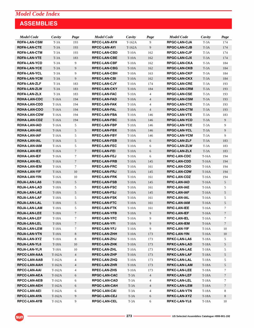
273 US Selected Assemblies Catalogue #999-901-192
RDFA-LAN-CSM T-3A 193
RDFA-LAN-CTE T-3A 193
RDFA-LAN-CTM T-3A 193
RDFA-LAN-VTE T-3A 183
RDFA-LAN-YCD T-3A 9
RDFA-LAN-YCE T-3A 9
RDFA-LAN-YCL T-3A 9
RDFA-LAN-YCM T-3A 9
RDFA-LAN-ZLF T-3A 183
RDFA-LAN-ZLW T-3A 183
RDFA-LAN-ZLX T-3A 183
RDHA-LAN-CDC T-16A 194
RDHA-LAN-CDD T-16A 194
RDHA-LAN-CDO T-16A 194
RDHA-LAN-CDW T-16A 194
RDHA-LAN-CDZ T-16A 194
RDHA-LAN-IAD T-16A 5
RDHA-LAN-IAE T-16A 5
RDHA-LAN-IAF T-16A 5
RDHA-LAN-IAL T-16A 5
RDHA-LAN-IAM T-16A 5
RDHA-LAN-IEE T-16A 7
RDHA-LAN-IEF T-16A 7
RDHA-LAN-IEL T-16A 7
RDHA-LAN-IEM T-16A 7
RDHA-LAN-YIF T-16A 10
RDHA-LAN-YIN T-16A 10
RDJA-LAN-LA6 T-18A 5
RDJA-LAN-LAD T-18A 5
RDJA-LAN-LAE T-18A 5
RDJA-LAN-LAF T-18A 5
RDJA-LAN-LAL T-18A 5
RDJA-LAN-LAM T-18A 5
RDJA-LAN-LEE T-18A 7
RDJA-LAN-LEF T-18A 7
RDJA-LAN-LEL T-18A 7
RDJA-LAN-LEM T-18A 7
RDJA-LAN-VTN T-18A 8
RDJA-LAN-XYZ T-18A 8
RDJA-LAN-YL6 T-18A 10
RDJA-LAN-YLR T-18A 10
RPCC-LAN-AAA T-162A 4
RPCC-LAN-AAB T-162A 4
RPCC-LAN-AAH T-162A 4
RPCC-LAN-AAI T-162A 4
RPCC-LAN-AEA T-162A 6
RPCC-LAN-AEB T-162A 6
RPCC-LAN-AEH T-162A 6
RPCC-LAN-AEI T-162A 6
RPCC-LAN-AYA T-162A 9
RPCC-LAN-AYB T-162A 9
RPCC-LAN-AYH T-162A 9
RPCC-LAN-AYI T-162A 9
RPEC-LAN-CBD T-10A 162
RPEC-LAN-CBE T-10A 162
RPEC-LAN-CBF T-10A 162
RPEC-LAN-CBG T-10A 162
RPEC-LAN-CBH T-10A 163
RPEC-LAN-CBI T-10A 162
RPEC-LAN-CJY T-10A 174
RPEC-LAN-CKY T-10A 184
RPEC-LAN-FAC T-10A 4
RPEC-LAN-FAD T-10A 4
RPEC-LAN-FAK T-10A 4
RPEC-LAN-FAL T-10A 4
RPEC-LAN-FBA T-10A 146
RPEC-LAN-FBC T-10A 146
RPEC-LAN-FBP T-10A 146
RPEC-LAN-FBX T-10A 146
RPEC-LAN-FBY T-10A 146
RPEC-LAN-FEB T-10A 6
RPEC-LAN-FEC T-10A 6
RPEC-LAN-FEI T-10A 6
RPEC-LAN-FEJ T-10A 6
RPEC-LAN-FRB T-10A 145
RPEC-LAN-FRC T-10A 161
RPEC-LAN-FRJ T-10A 145
RPEC-LAN-FRK T-10A 161
RPEC-LAN-FSB T-10A 145
RPEC-LAN-FSC T-10A 161
RPEC-LAN-FSJ T-10A 145
RPEC-LAN-FSK T-10A 161
RPEC-LAN-FTC T-10A 161
RPEC-LAN-FTK T-10A 161
RPEC-LAN-YFB T-10A 9
RPEC-LAN-YFC T-10A 9
RPEC-LAN-YFI T-10A 9
RPEC-LAN-YFJ T-10A 9
RPEC-LAN-ZHH T-10A 173
RPEC-LAN-ZHJ T-10A 173
RPEC-LAN-ZHK T-10A 173
RPEC-LAN-ZHL T-10A 173
RPEC-LAN-ZHP T-10A 173
RPEC-LAN-ZHQ T-10A 173
RPEC-LAN-ZHR T-10A 173
RPEC-LAN-ZHS T-10A 173
RPGC-LAN-CAC T-3A 4
RPGC-LAN-CAD T-3A 4
RPGC-LAN-CAH T-3A 4
RPGC-LAN-CAI T-3A 4
RPGC-LAN-CEJ T-3A 6
RPGC-LAN-CEL T-3A 6
RPGC-LAN-CJA T-3A 174
RPGC-LAN-CJB T-3A 174
RPGC-LAN-CJP T-3A 174
RPGC-LAN-CJX T-3A 174
RPGC-LAN-CKA T-3A 184
RPGC-LAN-CKB T-3A 184
RPGC-LAN-CKP T-3A 184
RPGC-LAN-CKX T-3A 184
RPGC-LAN-CRE T-3A 193
RPGC-LAN-CRM T-3A 193
RPGC-LAN-CSE T-3A 193
RPGC-LAN-CSM T-3A 193
RPGC-LAN-CTE T-3A 193
RPGC-LAN-CTM T-3A 193
RPGC-LAN-VTE T-3A 183
RPGC-LAN-YCD T-3A 9
RPGC-LAN-YCE T-3A 9
RPGC-LAN-YCL T-3A 9
RPGC-LAN-YCM T-3A 9
RPGC-LAN-ZLF T-3A 183
RPGC-LAN-ZLW T-3A 183
RPGC-LAN-ZLX T-3A 183
RPIC-LAN-CDC T-16A 194
RPIC-LAN-CDD T-16A 194
RPIC-LAN-CDO T-16A 194
RPIC-LAN-CDW T-16A 194
RPIC-LAN-CDZ T-16A 194
RPIC-LAN-IAD T-16A 5
RPIC-LAN-IAE T-16A 5
RPIC-LAN-IAF T-16A 5
RPIC-LAN-IAL T-16A 5
RPIC-LAN-IAM T-16A 5
RPIC-LAN-IEE T-16A 7
RPIC-LAN-IEF T-16A 7
RPIC-LAN-IEL T-16A 7
RPIC-LAN-IEM T-16A 7
RPIC-LAN-YIF T-16A 10
RPIC-LAN-YIN T-16A 10
RPKC-LAN-LA6 T-18A 5
RPKC-LAN-LAD T-18A 5
RPKC-LAN-LAE T-18A 5
RPKC-LAN-LAF T-18A 5
RPKC-LAN-LAL T-18A 5
RPKC-LAN-LAM T-18A 5
RPKC-LAN-LEE T-18A 7
RPKC-LAN-LEF T-18A 7
RPKC-LAN-LEL T-18A 7
RPKC-LAN-LEM T-18A 7
RPKC-LAN-VTN T-18A 8
RPKC-LAN-XYZ T-18A 8
RPKC-LAN-YL6 T-18A 10
Model Code Cavity Page Model Code Cavity Page Model Code Cavity Page
ASSEMBLIES
Model Code Index
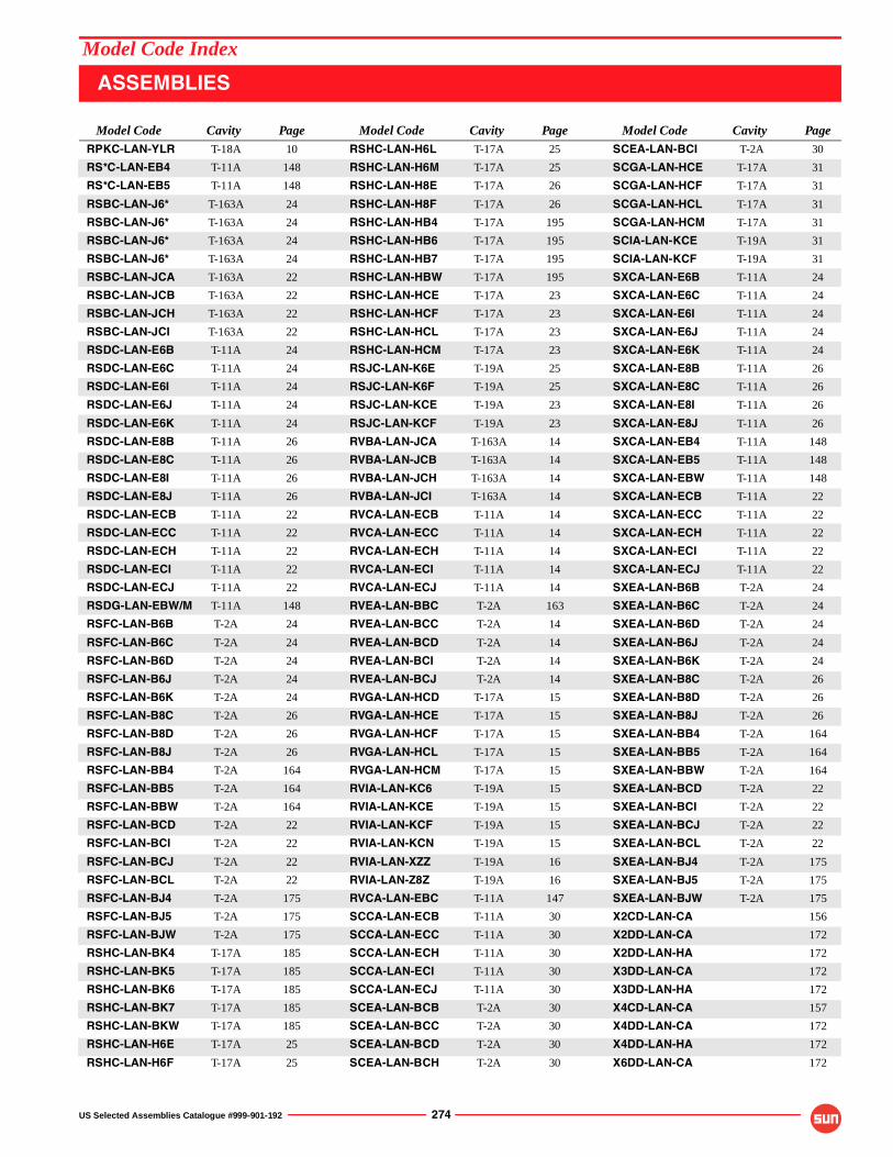
US Selected Assemblies Catalogue #999-901-192 274
RPKC-LAN-YLR T-18A 10
RS*C-LAN-EB4 T-11A 148
RS*C-LAN-EB5 T-11A 148
RSBC-LAN-J6* T-163A 24
RSBC-LAN-J6* T-163A 24
RSBC-LAN-J6* T-163A 24
RSBC-LAN-J6* T-163A 24
RSBC-LAN-JCA T-163A 22
RSBC-LAN-JCB T-163A 22
RSBC-LAN-JCH T-163A 22
RSBC-LAN-JCI T-163A 22
RSDC-LAN-E6B T-11A 24
RSDC-LAN-E6C T-11A 24
RSDC-LAN-E6I T-11A 24
RSDC-LAN-E6J T-11A 24
RSDC-LAN-E6K T-11A 24
RSDC-LAN-E8B T-11A 26
RSDC-LAN-E8C T-11A 26
RSDC-LAN-E8I T-11A 26
RSDC-LAN-E8J T-11A 26
RSDC-LAN-ECB T-11A 22
RSDC-LAN-ECC T-11A 22
RSDC-LAN-ECH T-11A 22
RSDC-LAN-ECI T-11A 22
RSDC-LAN-ECJ T-11A 22
RSDG-LAN-EBW/M T-11A 148
RSFC-LAN-B6B T-2A 24
RSFC-LAN-B6C T-2A 24
RSFC-LAN-B6D T-2A 24
RSFC-LAN-B6J T-2A 24
RSFC-LAN-B6K T-2A 24
RSFC-LAN-B8C T-2A 26
RSFC-LAN-B8D T-2A 26
RSFC-LAN-B8J T-2A 26
RSFC-LAN-BB4 T-2A 164
RSFC-LAN-BB5 T-2A 164
RSFC-LAN-BBW T-2A 164
RSFC-LAN-BCD T-2A 22
RSFC-LAN-BCI T-2A 22
RSFC-LAN-BCJ T-2A 22
RSFC-LAN-BCL T-2A 22
RSFC-LAN-BJ4 T-2A 175
RSFC-LAN-BJ5 T-2A 175
RSFC-LAN-BJW T-2A 175
RSHC-LAN-BK4 T-17A 185
RSHC-LAN-BK5 T-17A 185
RSHC-LAN-BK6 T-17A 185
RSHC-LAN-BK7 T-17A 185
RSHC-LAN-BKW T-17A 185
RSHC-LAN-H6E T-17A 25
RSHC-LAN-H6F T-17A 25
RSHC-LAN-H6L T-17A 25
RSHC-LAN-H6M T-17A 25
RSHC-LAN-H8E T-17A 26
RSHC-LAN-H8F T-17A 26
RSHC-LAN-HB4 T-17A 195
RSHC-LAN-HB6 T-17A 195
RSHC-LAN-HB7 T-17A 195
RSHC-LAN-HBW T-17A 195
RSHC-LAN-HCE T-17A 23
RSHC-LAN-HCF T-17A 23
RSHC-LAN-HCL T-17A 23
RSHC-LAN-HCM T-17A 23
RSJC-LAN-K6E T-19A 25
RSJC-LAN-K6F T-19A 25
RSJC-LAN-KCE T-19A 23
RSJC-LAN-KCF T-19A 23
RVBA-LAN-JCA T-163A 14
RVBA-LAN-JCB T-163A 14
RVBA-LAN-JCH T-163A 14
RVBA-LAN-JCI T-163A 14
RVCA-LAN-ECB T-11A 14
RVCA-LAN-ECC T-11A 14
RVCA-LAN-ECH T-11A 14
RVCA-LAN-ECI T-11A 14
RVCA-LAN-ECJ T-11A 14
RVEA-LAN-BBC T-2A 163
RVEA-LAN-BCC T-2A 14
RVEA-LAN-BCD T-2A 14
RVEA-LAN-BCI T-2A 14
RVEA-LAN-BCJ T-2A 14
RVGA-LAN-HCD T-17A 15
RVGA-LAN-HCE T-17A 15
RVGA-LAN-HCF T-17A 15
RVGA-LAN-HCL T-17A 15
RVGA-LAN-HCM T-17A 15
RVIA-LAN-KC6 T-19A 15
RVIA-LAN-KCE T-19A 15
RVIA-LAN-KCF T-19A 15
RVIA-LAN-KCN T-19A 15
RVIA-LAN-XZZ T-19A 16
RVIA-LAN-Z8Z T-19A 16
RVCA-LAN-EBC T-11A 147
SCCA-LAN-ECB T-11A 30
SCCA-LAN-ECC T-11A 30
SCCA-LAN-ECH T-11A 30
SCCA-LAN-ECI T-11A 30
SCCA-LAN-ECJ T-11A 30
SCEA-LAN-BCB T-2A 30
SCEA-LAN-BCC T-2A 30
SCEA-LAN-BCD T-2A 30
SCEA-LAN-BCH T-2A 30
SCEA-LAN-BCI T-2A 30
SCGA-LAN-HCE T-17A 31
SCGA-LAN-HCF T-17A 31
SCGA-LAN-HCL T-17A 31
SCGA-LAN-HCM T-17A 31
SCIA-LAN-KCE T-19A 31
SCIA-LAN-KCF T-19A 31
SXCA-LAN-E6B T-11A 24
SXCA-LAN-E6C T-11A 24
SXCA-LAN-E6I T-11A 24
SXCA-LAN-E6J T-11A 24
SXCA-LAN-E6K T-11A 24
SXCA-LAN-E8B T-11A 26
SXCA-LAN-E8C T-11A 26
SXCA-LAN-E8I T-11A 26
SXCA-LAN-E8J T-11A 26
SXCA-LAN-EB4 T-11A 148
SXCA-LAN-EB5 T-11A 148
SXCA-LAN-EBW T-11A 148
SXCA-LAN-ECB T-11A 22
SXCA-LAN-ECC T-11A 22
SXCA-LAN-ECH T-11A 22
SXCA-LAN-ECI T-11A 22
SXCA-LAN-ECJ T-11A 22
SXEA-LAN-B6B T-2A 24
SXEA-LAN-B6C T-2A 24
SXEA-LAN-B6D T-2A 24
SXEA-LAN-B6J T-2A 24
SXEA-LAN-B6K T-2A 24
SXEA-LAN-B8C T-2A 26
SXEA-LAN-B8D T-2A 26
SXEA-LAN-B8J T-2A 26
SXEA-LAN-BB4 T-2A 164
SXEA-LAN-BB5 T-2A 164
SXEA-LAN-BBW T-2A 164
SXEA-LAN-BCD T-2A 22
SXEA-LAN-BCI T-2A 22
SXEA-LAN-BCJ T-2A 22
SXEA-LAN-BCL T-2A 22
SXEA-LAN-BJ4 T-2A 175
SXEA-LAN-BJ5 T-2A 175
SXEA-LAN-BJW T-2A 175
X2CD-LAN-CA 156
X2DD-LAN-CA 172
X2DD-LAN-HA 172
X3DD-LAN-CA 172
X3DD-LAN-HA 172
X4CD-LAN-CA 157
X4DD-LAN-CA 172
X4DD-LAN-HA 172
X6DD-LAN-CA 172
Model Code Cavity Page Model Code Cavity Page Model Code Cavity Page
ASSEMBLIES
Model Code Index
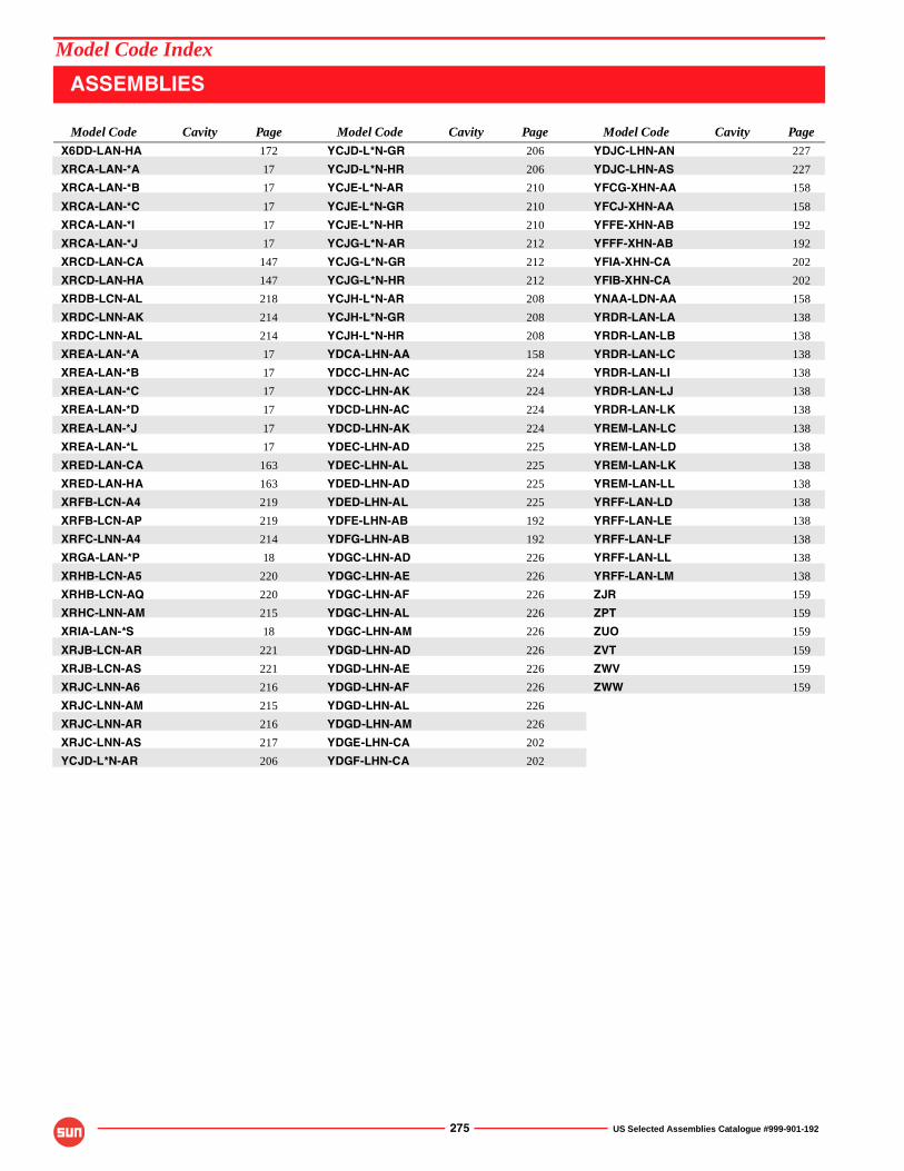
275 US Selected Assemblies Catalogue #999-901-192
X6DD-LAN-HA 172
XRCA-LAN-*A 17
XRCA-LAN-*B 17
XRCA-LAN-*C 17
XRCA-LAN-*I 17
XRCA-LAN-*J 17
XRCD-LAN-CA 147
XRCD-LAN-HA 147
XRDB-LCN-AL 218
XRDC-LNN-AK 214
XRDC-LNN-AL 214
XREA-LAN-*A 17
XREA-LAN-*B 17
XREA-LAN-*C 17
XREA-LAN-*D 17
XREA-LAN-*J 17
XREA-LAN-*L 17
XRED-LAN-CA 163
XRED-LAN-HA 163
XRFB-LCN-A4 219
XRFB-LCN-AP 219
XRFC-LNN-A4 214
XRGA-LAN-*P 18
XRHB-LCN-A5 220
XRHB-LCN-AQ 220
XRHC-LNN-AM 215
XRIA-LAN-*S 18
XRJB-LCN-AR 221
XRJB-LCN-AS 221
XRJC-LNN-A6 216
XRJC-LNN-AM 215
XRJC-LNN-AR 216
XRJC-LNN-AS 217
YCJD-L*N-AR 206
YCJD-L*N-GR 206
YCJD-L*N-HR 206
YCJE-L*N-AR 210
YCJE-L*N-GR 210
YCJE-L*N-HR 210
YCJG-L*N-AR 212
YCJG-L*N-GR 212
YCJG-L*N-HR 212
YCJH-L*N-AR 208
YCJH-L*N-GR 208
YCJH-L*N-HR 208
YDCA-LHN-AA 158
YDCC-LHN-AC 224
YDCC-LHN-AK 224
YDCD-LHN-AC 224
YDCD-LHN-AK 224
YDEC-LHN-AD 225
YDEC-LHN-AL 225
YDED-LHN-AD 225
YDED-LHN-AL 225
YDFE-LHN-AB 192
YDFG-LHN-AB 192
YDGC-LHN-AD 226
YDGC-LHN-AE 226
YDGC-LHN-AF 226
YDGC-LHN-AL 226
YDGC-LHN-AM 226
YDGD-LHN-AD 226
YDGD-LHN-AE 226
YDGD-LHN-AF 226
YDGD-LHN-AL 226
YDGD-LHN-AM 226
YDGE-LHN-CA 202
YDGF-LHN-CA 202
YDJC-LHN-AN 227
YDJC-LHN-AS 227
YFCG-XHN-AA 158
YFCJ-XHN-AA 158
YFFE-XHN-AB 192
YFFF-XHN-AB 192
YFIA-XHN-CA 202
YFIB-XHN-CA 202
YNAA-LDN-AA 158
YRDR-LAN-LA 138
YRDR-LAN-LB 138
YRDR-LAN-LC 138
YRDR-LAN-LI 138
YRDR-LAN-LJ 138
YRDR-LAN-LK 138
YREM-LAN-LC 138
YREM-LAN-LD 138
YREM-LAN-LK 138
YREM-LAN-LL 138
YRFF-LAN-LD 138
YRFF-LAN-LE 138
YRFF-LAN-LF 138
YRFF-LAN-LL 138
YRFF-LAN-LM 138
ZJR 159
ZPT 159
ZUO 159
ZVT 159
ZWV 159
ZWW 159
Model Code Cavity Page Model Code Cavity Page Model Code Cavity Page
ASSEMBLIES
Model Code Index
US Selected Assemblies Catalogue #999-901-192 276
Warranty
WARRANTY INFORMATION,PERFORMANCE ASSURANCE,
AND APPLICATION LIMITATIONS
Caution
Performance Assurance
Limited Warranty
Sun Hydraulics Corporation manufactures a variety of cartridge valves that will fit into the same Sun cavity. Each cartridge is marked with a seven-digit part identification code and a four-digit date code, stamped on the hex surfaces. Designers and users of Sun components are advised that physical interchangeability of cartridges does not necessarily mean functional interchangeability. When
replacing any Sun cartridges, users should first check with the manufacturer's service literature, their local Sun distributor, or the Sun factory before making any part substitutions.
NOTE: To avoid serious injury, the manufacturer's service manual must be consulted before working on any hydraulic system.
All Sun cartridges are individually tested at the factory and preset to specific pressure or flow settings where indicated in this catalog. However, as the actual performance of buyers' equipment cannot be reproduced in Sun's testing laboratory,
assurance of suitability of all Sun products in the buyer's application is the responsibility of the buyer. This is typically accomplished by the manufacture of a prototype followed by a test or qualification program on the part of the buyer.
Sun's product designs and manufacturing facilities have been specifically developed to provide products for commercial, industrial and mobile hydraulic applications and Sun's products are only warranted for this type of use. Sun's distributors are not authorized to approve the use of Sun products in any of the following applications:
� Any product that comes under the Federal Highway Safety Act, namely steering or braking systems for passenger-carrying vehicles or on-highway trucks.
� Aircraft or space vehicles.� Ordnance equipment.� Life support equipment.� Any end product that, when sold, comes under the U.S.
Nuclear Regulatory Commission rules and regulations.
Specific written approval for any application of Sun products in any of the above named applications should be obtained from Sun Hydraulics Corporation. Consultation with Sun distributors or factory engineers is advised in unusual situations where applicability is questionable.
Sun Hydraulics Corporation warrants its products free from defects in material, workmanship, and design for a period of three years after installation, provided the installation date is less than one year after manufacture. �O-rings� and seals are specifically exempted from this warranty. In no instance is there any warranty of fitness for a particular use and Sun Hydraulics Corporation cannot and does not accept responsibility of any type for any of its products that have been subjected to improper installation, improper application, negligence, tampering, or abuse, or which have been repaired or
altered outside of the Sun Hydraulics factory. Sun Hydraulics Corporation�s liability under this warranty shall extend only to replacement or correction, f.o.b. our factory, of any defective part or product determined by inspection as not conforming to this warranty. We make no other warranties, expressed or implied, and are not responsible for any consequential damages resulting from use by any buyer or user, our liability being limited to the value of product sold or obligation to replace a defective part.
Application Limitations
Related Documents