SUN FIRE™ X4170, X4270, AND X4275 SERVER ARCHITECTURE Optimizing Performance, Density, and Expandability to Maximize Datacenter Value White Paper April 2009 Abstract In compact 1U and 2U form factors, the Sun Fire X4170, X4270, and X4275 servers combine the power of a new generation of Intel Xeon processors with Sun’s system engineering expertise. Based on Sun’s Open Network System design approach, these servers offer the needed performance, density, and expandability to satisfy demanding datacenter applications, especially for virtualization and consolidation initiatives. This white paper describes the architecture of the Sun Fire X4170, X4270, and X4275 servers, including the processor technology, I/O subsystem, built-in system management features, and range of supported operating systems.

Welcome message from author
This document is posted to help you gain knowledge. Please leave a comment to let me know what you think about it! Share it to your friends and learn new things together.
Transcript
SUN FIRE™ X4170, X4270, AND X4275SERVER ARCHITECTUREOptimizing Performance, Density, and Expandability to Maximize Datacenter Value
White PaperApril 2009
Abstract
In compact 1U and 2U form factors, the Sun Fire X4170, X4270, and X4275 servers combine the power of a new
generation of Intel Xeon processors with Sun’s system engineering expertise. Based on Sun’s Open Network
System design approach, these servers offer the needed performance, density, and expandability to satisfy
demanding datacenter applications, especially for virtualization and consolidation initiatives. This white paper
describes the architecture of the Sun Fire X4170, X4270, and X4275 servers, including the processor technology, I/O
subsystem, built-in system management features, and range of supported operating systems.

Sun Microsystems, Inc.
This Page Intentionally Left Blank

Sun Microsystems, Inc.
Table of Contents
Executive Summary . . . . . . . . . . . . . . . . . . . . . . . . . . . . . . . . . . . . . . . . . . . . . . . . 1
Managing Capacity and Complexity . . . . . . . . . . . . . . . . . . . . . . . . . . . . . . . . . . . . 2
Introducing the Sun Fire™ X4170, X4270, and X4275 servers . . . . . . . . . . . . . . . . . . . . 2
Comparing the Sun Fire X4170, X4270, and X4275 servers . . . . . . . . . . . . . . . . . . . . . 4
A choice of operating systems . . . . . . . . . . . . . . . . . . . . . . . . . . . . . . . . . . . . . . . . 6
The Intel Advantage . . . . . . . . . . . . . . . . . . . . . . . . . . . . . . . . . . . . . . . . . . . . . . . . 7
New Intel Core Microarchitecture. . . . . . . . . . . . . . . . . . . . . . . . . . . . . . . . . . . . . . . . 7
Modular architecture . . . . . . . . . . . . . . . . . . . . . . . . . . . . . . . . . . . . . . . . . . . . . . 10
Power management technologies . . . . . . . . . . . . . . . . . . . . . . . . . . . . . . . . . . . . 10
Intel Xeon Processor 5500 platform . . . . . . . . . . . . . . . . . . . . . . . . . . . . . . . . . . . . . 11
Sun Fire X4170, X4270, and X4275 Server Architectures . . . . . . . . . . . . . . . . . . . . 12
Sun Fire X4170 system-level architecture . . . . . . . . . . . . . . . . . . . . . . . . . . . . . . . . . 12
Sun Fire X4170 server overview. . . . . . . . . . . . . . . . . . . . . . . . . . . . . . . . . . . . . . . . . 13
Sun Fire X4170 server enclosure . . . . . . . . . . . . . . . . . . . . . . . . . . . . . . . . . . . . . . 14
Sun Fire X4170 server front and rear perspectives . . . . . . . . . . . . . . . . . . . . . . . . 14
Sun Fire X4270 system-level architecture . . . . . . . . . . . . . . . . . . . . . . . . . . . . . . . . . 16
Sun Fire X4270 server overview. . . . . . . . . . . . . . . . . . . . . . . . . . . . . . . . . . . . . . . . . 17
Sun Fire X4270 server enclosure . . . . . . . . . . . . . . . . . . . . . . . . . . . . . . . . . . . . . . 17
Sun Fire X4270 server front and rear perspectives . . . . . . . . . . . . . . . . . . . . . . . . 18
Sun Fire X4275 system-level architecture . . . . . . . . . . . . . . . . . . . . . . . . . . . . . . . . . 19
Sun Fire X4275 server overview. . . . . . . . . . . . . . . . . . . . . . . . . . . . . . . . . . . . . . . . . 20
Sun Fire X4275 server enclosure . . . . . . . . . . . . . . . . . . . . . . . . . . . . . . . . . . . . . . 20
Sun Fire X4275 server front and rear perspectives . . . . . . . . . . . . . . . . . . . . . . . . 21
System platform . . . . . . . . . . . . . . . . . . . . . . . . . . . . . . . . . . . . . . . . . . . . . . . . . . . . 22
Memory subsystem. . . . . . . . . . . . . . . . . . . . . . . . . . . . . . . . . . . . . . . . . . . . . . . . . . 22
Memory population guidelines. . . . . . . . . . . . . . . . . . . . . . . . . . . . . . . . . . . . . . . 23
I/O subsystem. . . . . . . . . . . . . . . . . . . . . . . . . . . . . . . . . . . . . . . . . . . . . . . . . . . . . . 23
System network interfaces . . . . . . . . . . . . . . . . . . . . . . . . . . . . . . . . . . . . . . . . . . 24
PCIe 2.0 expansion bus . . . . . . . . . . . . . . . . . . . . . . . . . . . . . . . . . . . . . . . . . . . . . 24
Integrated storage . . . . . . . . . . . . . . . . . . . . . . . . . . . . . . . . . . . . . . . . . . . . . . . . 26
Enclosure features . . . . . . . . . . . . . . . . . . . . . . . . . . . . . . . . . . . . . . . . . . . . . . . . . . 30
Power distribution . . . . . . . . . . . . . . . . . . . . . . . . . . . . . . . . . . . . . . . . . . . . . . . . 30
Fan assemblies . . . . . . . . . . . . . . . . . . . . . . . . . . . . . . . . . . . . . . . . . . . . . . . . . . . 31
Rack mounting . . . . . . . . . . . . . . . . . . . . . . . . . . . . . . . . . . . . . . . . . . . . . . . . . . . 31
RAS features . . . . . . . . . . . . . . . . . . . . . . . . . . . . . . . . . . . . . . . . . . . . . . . . . . . . . . . 32
ILOM Service Processor and System Management . . . . . . . . . . . . . . . . . . . . . . . . 34
Sun ILOM service processor . . . . . . . . . . . . . . . . . . . . . . . . . . . . . . . . . . . . . . . . . . . 34
Optimizing management flexibility . . . . . . . . . . . . . . . . . . . . . . . . . . . . . . . . . . . 35
Remote keyboard, video, mouse, and storage (RKVMS) . . . . . . . . . . . . . . . . . . . . 37
Sun Microsystems, Inc.
Intelligent platform management interface. . . . . . . . . . . . . . . . . . . . . . . . . . . . . 38
New features in ILOM3.0 . . . . . . . . . . . . . . . . . . . . . . . . . . . . . . . . . . . . . . . . . . . 39
SNMP . . . . . . . . . . . . . . . . . . . . . . . . . . . . . . . . . . . . . . . . . . . . . . . . . . . . . . . . . . 40
Sun™ xVM Ops Center . . . . . . . . . . . . . . . . . . . . . . . . . . . . . . . . . . . . . . . . . . . . . . . . 41
Enterprise-Class Software Support . . . . . . . . . . . . . . . . . . . . . . . . . . . . . . . . . . . . 42
The Solaris™ Operating System . . . . . . . . . . . . . . . . . . . . . . . . . . . . . . . . . . . . . . . . . 42
Linux environments . . . . . . . . . . . . . . . . . . . . . . . . . . . . . . . . . . . . . . . . . . . . . . . . . 44
Microsoft Windows environments . . . . . . . . . . . . . . . . . . . . . . . . . . . . . . . . . . . . . . 44
VMware support . . . . . . . . . . . . . . . . . . . . . . . . . . . . . . . . . . . . . . . . . . . . . . . . . . . . 44
Summary . . . . . . . . . . . . . . . . . . . . . . . . . . . . . . . . . . . . . . . . . . . . . . . . . . . . . . . 46
For more information . . . . . . . . . . . . . . . . . . . . . . . . . . . . . . . . . . . . . . . . . . . . . . 46
1 Executive Summary Sun Microsystems, Inc.
Executive Summary
Datacenter complexity, energy, and cost issues continue to plague businesses and their
ability to operate effectively within tight budget constraints. In recent years, an
increase in the number of collaborative, Web, and data-centric applications has driven
up the number of datacenter compute servers, adding to the administrative workload
and compounding an already difficult IT management task. Complexity can sometimes
result in severe business impacts, slowing productivity, extending development cycles,
and delaying time to market. While datacenters try to cope with increasing complexity,
they strive to control energy and other operating costs, while still keeping pace with
the growing demand for computing and storage resources. To achieve greater business
and datacenter efficiencies and enhance agility, many small businesses and larger
companies are turning to consolidation and implementing virtualization initiatives.
For more than 25 years, Sun has focused on solving customer problems by engineering
solutions based on innovative technologies that deliver differentiated value. Sun’s Open
Network System approach combines innovative technologies, cost-effective and
industry-standard components, and Sun’s expertise in delivering dense, high-
performance systems. This focus, along with an emphasis on eco-responsibility, is
evident in designs of a new Sun platform family — the Sun Fire™ X4170, X4270, and
X4275 servers — which are ideal for supporting consolidation and virtualization.
Using state-of-the-art Intel® Xeon® processor technology (codenamed “Nehalem”), Sun
has engineered powerful 1U and 2U systems that are well-suited for HPC, grid
computing, database, Web infrastructure, as well as consolidation and virtualization.
These systems offer density and expandability in compute, memory, storage, and I/O
subsystems, including the integration of low-latency, enterprise-quality solid state disk
(SSD) drive technology. These systems are also highly energy-efficient and offer flexible
support for multiple operating systems — the Solaris™ and OpenSolaris™ Operating
Systems, Linux, Microsoft Windows, and VMware.
The Sun Fire X4170, X4270, and X4275 servers showcase Intel’s talent for creating high-
performance commodity chipsets along with Sun’s advanced engineering and quality
system design. Engineered for mission-critical availability, these servers feature several
redundant and hot-swappable components and built-in system management tools.
With efficient front-to-back air flow, highly efficient power supplies, and Intel’s built-in
processor power management technologies, these servers are engineered to conserve
valuable energy resources, which helps to lower day-to-day operational expenses. By
taking advantage of Sun’s expertise in Open Network System design, these servers
deliver innovation that optimizes operational efficiency and economics in
the datacenter.
2 Managing Capacity and Complexity Sun Microsystems, Inc.
Chapter 1
Managing Capacity and Complexity
Introducing the Sun Fire™ X4170, X4270, and X4275 serversTo help IT managers optimize value and reduce complexity in the infrastructure, Sun
offers a new series of Intel® Xeon® processor-based systems — the Sun Fire X4170,
X4270, and X4275 servers — based on Sun’s Open Network System approach. This
approach blends cost-effective, industry-standard components with innovative
technologies, yielding compact 1U and 2U servers with unprecedented density, high
performance, and energy efficiency. The Sun Fire X4170, X4270, and X4275 servers offer:
• Advanced levels of performance.The Sun Fire X4170, X4270, and X4275 servers share a
common motherboard that contains two sockets for Intel® Xeon® Processor 5500
Series (formerly Nehalem-EP). With new HyperThreading technology, these CPUs can
provide twice as many compute threads as previous generation processors. They also
support enhanced power management features, the new QuickPath Interconnect,
and Intel “Turbo Boost” technology that helps to deliver new levels of performance
while lowering power consumption.
• Remarkable density. Density is the cornerstone of the Sun Fire X4170, X4270, and
X4275 server designs. When populated in a 42-rack unit (RU) enclosure, the 1U Sun
Fire X4170 server facilitates a single rack with up to 84 processors, 756 DIMM slots
and 126 PCI Express (PCIe) 2.0 slots. In a single 2U chassis, the Sun Fire X4275 server
supports up to 12 terabytes of internal storage (based on 3.5-inch SATA devices).
These servers provide the density needed for consolidation and virtualization
initiatives — many smaller servers can be merged into a single Sun Fire X4170,
X4270, or X4275 server to conserve space, lower energy expense, and reduce costly
administrative talent. Support for multiple operating systems helps to streamline
consolidation, simplify virtualization, and diminish server sprawl.
• Extensive system expandability. The ability to expand a server over time reduces the
need for additional capital acquisitions and lowers application lifecycle costs. The 1U
Sun Fire X4170 server enables a maximum of eight internal 2.5-inch hard disk devices
(HDDs) while the 2U Sun Fire X4270 server provides up to sixteen 2.5-inch devices and
up to six 8-lane PCIe 2.0 slots. With an innovative new 2U chassis enclosure that can
house 3.5-inch devices, the Sun Fire X4275 server supports up to twelve internal HDDs
and up to six PCIe 2.0 slots. All three server models are available with four on-board
Gigabit Ethernet ports, and can be configured with either SAS or SATA hard disk
drives. In addition, these servers are designed from the ground up to accept low-
latency solid state disks (SSDs) for performance-intensive applications. Because these
servers can easily integrate enterprise-quality flash technology and offer such
expandability, they can scale easily to support new users, more transactions, and
new 32-bit or 64-bit applications, enhancing longevity and increasing overall ROI.

3 Managing Capacity and Complexity Sun Microsystems, Inc.
• Improved energy efficiency. Sun offers a portfolio of eco-responsible products and
computing solutions to address customers’ needs to reduce energy consumption. In
the Sun Fire X4170, X4270, and X4275 servers, the Intel Xeon Processor 5500 Series
incorporates new technologies that decrease power consumption when processing
workloads diminish. When the workload is low, the new Intel® Core
Microarchitecture (codenamed Nehalem) adjusts power use, reducing processor
frequency, limiting power to unused execution units in each core, or temporarily
disabling “Turbo Boost” features, which together can help to decrease power and
cooling requirements. High-efficiency power supplies in the server chassis also lower
overall power consumption. Variable speed fans, disk carrier design, and front-to-back
air flow help to effectively cool the system and maintain appropriate processor and
system ambient temperatures, which also help to minimize the energy footprint.
• Enterprise-class high availability. The Sun Fire X4170, X4270, and X4275 servers are
designed with enterprise-class RAS (Reliability, Availability, and Serviceability)
features. To maximize uptime, systems include redundant hot-swappable fans and
are configurable with redundant hot-swappable power supplies. Using a Sun
StorageTek™ SAS RAID Host Bus Adapter (HBA), internal SAS or SATA disk drives can be
configured for RAID 0, 1, 1E, 10, 5, 5EE, 50, 6, and 60 —when mirroring is
implemented, drives are also hot-swappable. Four integrated Gigabit Ethernet ports
enhance network availability — without consuming a PCIe 2.0 slot — and can be
implemented in failover configurations. On-board system management tools
encourage remote, proactive monitoring and intervention.
• Simplified system management. To support out-of-band management, the Sun Fire
X4170, X4270, and X4275 servers incorporate a service processor that features robust
“lights-out” management capabilities. This built-in functionality allows
administrators to monitor and manage systems remotely, enabling corrective action
and minimizing unplanned downtime. New “side-band” management capabilities
allow one of the four on-board Ethernet ports to be configured for system
management, which can reduce the number of network switch connections needed.
The Sun Fire X4170, X4270, and X4275 servers combine powerful compute performance
with expandable storage, memory, and I/O resources. As a result, these systems are
designed to scale up, scale out, and scale within, enabling implementation in a wide
range of application architectures:
• Scale-up architectures.With multiple cores and processing threads, these servers are
well-suited to scale for growing workloads that deliver Web, database, and other key
infrastructure services.
• Scale-out architectures.With the Intel QuickPath interconnect technology, large
memory capacities, internal storage, four Gigabit Ethernet ports, and high-
bandwidth PCIe 2.0 expansion for high-speed system interconnects (such as fiber
4 Managing Capacity and Complexity Sun Microsystems, Inc.
channel and InfiniBand), these servers can scale to solve complex computing
problems that demand intensive compute power and data bandwidth.
• Scale-within.With the ability to support industry-leading virtualization software
(including VMware, Microsoft Hyper-V, and Sun xVM, these servers are ideal systems
to consolidate applications within a single extensible platform.
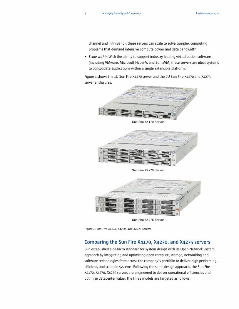
Figure 1 shows the 1U Sun Fire X4170 server and the 2U Sun Fire X4270 and X4275
server enclosures.
Figure 1. Sun Fire X4170, X4270, and X4275 servers
Comparing the Sun Fire X4170, X4270, and X4275 serversSun established a de-facto standard for system design with its Open Network System
approach by integrating and optimizing open compute, storage, networking and
software technologies from across the company's portfolio to deliver high performing,
efficient, and scalable systems. Following the same design approach, the Sun Fire
X4170, X4270, X4275 servers are engineered to deliver operational efficiencies and
optimize datacenter value. The three models are targeted as follows:
Sun Fire X4270 Server
Sun Fire X4170 Server
Sun Fire X4275 Server

5 Managing Capacity and Complexity Sun Microsystems, Inc.
• The Sun Fire X4170 server is a compact enterprise-class x64 server that can power
demanding mission-critical back office applications.
• The Sun Fire X4270 server is ideal for virtualization initiatives in branch office or
departmental settings, or for moderate complexity data center consolidation needs.
It features excellent expandability for memory, I/O, and a large number of internal
drives, which helps to support demanding virtualization requirements.
• The Sun Fire X4275 server is an ideal storage server to drive near-line storage
solutions for rich media or data warehousing applications. Its high density and
storage capabilities encourage substantial savings in cost, energy usage, and
datacenter space, which helps to optimize value.
Table 1 summarizes features of the Sun Fire X4170, X4270, X4275 server platforms.
Table 1. Feature Comparison for Sun Fire X4170, X4270, and X4275 servers
Feature Sun Fire X4170 Server Sun Fire X4270 Server Sun Fire X4275 Server
Chassis 1U 2U 2U
Number of CPU sockets 2 2 2
Supported processor type Intel® Xeon® Processor 5500 Series
Intel® Xeon® Processor 5500 Series
Intel® Xeon® Processor 5500 Series
Processor system interconnect
Intel® QuickPath Interconnect
Intel® QuickPath Interconnect
Intel® QuickPath Interconnect
Number of memory slots 18 18 18
Memory capacity Up to 144 GB (using 8 GB ECC RDIMMs)
Up to 144 GB (using 8 GB ECC RDIMMs)
Up to 144 GB (using 8 GB ECC RDIMMs)
Memory type DDR3 RDIMM DDR3 RDIMM DDR3 RDIMM
Internal storage: Supported device size
2.5-inch 2.5-inch 3.5-inch
Internal storage: Number of devices and types
Up to 8 SAS/SATA HDDs (SAS RAID HBA required) or 6 SATA HDDs or 4 SSDs (without an HBA)
Up to 16 SAS/SATA HDDs or 8 SATA SSDs (SAS RAID HBA required)
Up to 12 SAS/SATA HDDs or 8 SATA SSDs (SAS RAID HBA required)
Removable media Optional SATA DVD/RW; internal USB port and compact flash socket for flexible internal boot devices
Optional SATA DVD/RW; internal USB port and compact flash socket for flexible internal boot devices
No DVD/RW option; internal USB port and compact flash socket for flexible internal boot devices
Number of PCIe 2.0 slots Three total (1 x16, 2 x8)
Six total (all x8) Six total (all x8)
Number of GigE ports 4 on-board 4 on-board 4 on-board
Number of USB ports 2 front, 2 rear, 1 internal
2 front, 2 rear, 1 internal
2 rear, 1 internal
System management On-board ILOM service processor. Side-band management via on-board GigE port or through 10/100 Ethernet system management port
RAS components Hot swappable and redundant power supplies, fans, disk drives; RAID 0, 1, 10, 1E, 5, 6, 50, 5EE, 60 provided via optional SAS RAID HBA
OS support Solaris OS, OpenSolaris, Linux (32/64-bit Red Hat or SuSE Linux), Microsoft Windows, VMware ESX Server

6 Managing Capacity and Complexity Sun Microsystems, Inc.
As Table 1 shows, the systems share a number of features, including:
• Up to two Intel Xeon Processor 5500 Series (codenamed Nehalem-EP)
• Integrated memory controller supporting up to 1333 MT/s registered DDR3 memory
modules (memory is organized in three channels per processor)
• Multiple point-to-point Intel QuickPath technology-based interconnects
• Turbo Boost mode and HyperThreading capabilities
• Intel 5520 chipset (Tylersburg-36D) and Intel 82801JR I/O Controller Hub (ICH10R)
• Large-capacity internal storage, including support for solid state drives (SSDs) as well
as hard disk drives (HDDs)
• PCIe 2.0 expandability
• Built-in quad Gigabit Ethernet support
• An on-board ILOM service processor for system management
• Enterprise-class RAS features including redundant, hot-swappable power supplies,
fans, and drives
• Support for multiple operating systems
Notable differences between the Sun Fire X4170, X4270, and X4275 servers include:
• Chassis enclosure (1U versus 2U)
• Maximum number of devices supported for internal storage
• Support for 2.5-inch versus 3.5-inch internal storage devices
• PCI 2.0 expansion capabilities (three PCIe 2.0 slots versus six PCIe 2.0 slots)
Multiple off-the-shelf configurations of each platform are available, along with a wide
spectrum of options to tailor each system for specific workload requirements. The Sun
Fire X4170, X4270, and X4275 servers offer the density and configurability necessary to
realize operational, administrative, and energy cost-savings — the goals of many IT
strategic plans.
A choice of operating systems To optimize flexibility and investment protection, Sun Fire X4170, X4270, and X4275
servers support a choice of operating systems, including:
• Solaris Operating System (OS)
• OpenSolaris Operating System
• Linux operating systems (32/64-bit Red Hat or SuSE Linux)
• Microsoft Windows Server
• VMware ESX Server
Chapter 5 describes the OS releases supported as of this writing. Please see
sun.com/x64 for the latest information on supported operating systems and
environments.
7 The Intel Advantage Sun Microsystems, Inc.
Chapter 2
The Intel Advantage
Sun Microsystems, Inc. collaborates closely with Intel Corporation to bring to market a
broad server family based on the latest Intel® Xeon® processor technology. In the Sun
Fire X4170, X4270, and X4275 servers, Sun’s well-known system engineering expertise
combines with Intel’s processor design proficiency to emphasize performance, quality,
reliability, and eco-responsibility. Engineers at both companies work together to
optimize system performance under the Solaris Operating System (OS) as well as under
other operating environments. Looking to the future, Sun and Intel cooperate in efforts
to enhance the Solaris OS, Java™ technologies, and other functionality that
complements Intel Xeon processor and Sun server designs.
The Sun Fire X4170, X4270, and X4275 servers incorporate Intel Xeon Processor 5500
Series (formerly codenamed Nehalem-EP), which includes the revolutionary new
QuickPath interconnect and the Nehalem microarchitecture. Each server incorporates a
common motherboard populated with up to two processors, allowing the system to
deliver quick response times and high throughput for performance-hungry applications.
Compatible with a legacy of IA-32 software, these 64-bit processors support a large
volume of existing 32-bit applications as well as emerging 64-bit applications.
This chapter introduces the new Intel Xeon processors and microarchitecture used in
this Sun server family. For detailed information on these components, see the Web site
sun.com/x64.
New Intel Core Microarchitecture With each release of a new processor series, Intel tends to alternate between
enhancing the manufacturing process (shrinking the processor die) and redesigning the
core microarchitecture. Over a year ago, Intel transitioned to a 45nm manufacturing
process that enabled smaller transistors, allowing the previous processor generation to
consume less power, achieve faster switching times, and provide greater on-die density
than the generation before. This year, Intel is introducing a totally new
microarchitecture design (codenamed “Nehalem”) in the Intel Xeon Processor 5500
Series — at the same time reaping the benefits from its previous expertise with 45nm
silicon manufacturing.
This new Intel Xeon processor generation is targeted at delivering optimal performance
for bandwidth-intensive, threaded applications, with a microarchitecture that features
significant innovations over previous designs:
• Intel® QuickPath technology. This new technology provides a high-speed, point-to-
point interconnect between processors, memory, and I/O. The Intel QuickPath
interconnect (QPI) links processors in a distributed shared memory design that

8 The Intel Advantage Sun Microsystems, Inc.
enables high bandwidth and low latency memory access. Because it is a point-to-
point interconnect, processors do not contend for a single bus when accessing
memory and I/O, and do not compete for bus bandwidth, which enhances scalability.
Each QPI port includes two unidirectional links that support from 4.8 up to 6.4 GT/s
per link, enabling up to 12.8 GB/s bandwidth in each direction for a total bandwidth
of 25.6 GB/s — significantly higher than previous bus designs.
• Multiple processor cores. The microarchitecture design scales from 2 to 8 cores per
die, with four cores in the Intel Xeon Processor 5500 Series.
• Integrated DDR3 memory controller. Implemented as a separate component in earlier
architectures, the memory controller is now integrated on the processor die. The
processor design creates a Non-Uniform Memory Access (NUMA)-style memory
architecture since each processor in multi-socketed systems can access local memory
(connected to the local memory controller) as well as remote memory connected to
the second processor.
In addition to independent channel mode operation in which each memory channel
supports direct memory access, the integrated memory controller also supports the
following two modes:
– Memory channel mode increases reliability through memory mirroring. In this
mode, two memory channels operate as mirrors of each other. The same content
is written to both channels simultaneously, creating data redundancy. As a
consequence of mirroring, the amount of usable system memory reduces to half
of the total physical memory installed. To use memory channel mode, both
channels must be populated with identical DIMM types.
– Lockstep channel mode operates two memory channels in lockstep, increasing the reliability of each memory operation. In this mode, the cache line is split
across two channels, both channels must be populated identically, and memory mirroring and sparing are not supported.
Regardless of the mode in use, the integrated memory controller also increases data
protection through support for demand and patrol scrubbing and single device data
correction (SDDC).
– Demand and patrol scrubbing technology proactively searches system memory,
repairing correctable errors. In the case of uncorrectable errors, the algorithm
permanently marks the memory location as unreadable.
– x4 and x8 SDDC offers an advanced form of ECC technology that protects
computer memory systems from any single memory chip failure. This
technology can detect and correct 1-bit to 4-bit internal data and data pin
failures within one DDR memory device, and detect up to 8-bit internal data and
data pin failures within two DDR memory devices. SDDC performs this function
by scattering the bits of an ECC word across multiple memory chips, such that
the failure of any one memory chip affects only one ECC bit. (Note: x8 SDDC is
only available in lockstep channel mode)

9 The Intel Advantage Sun Microsystems, Inc.
• Advanced cache model. Each core has an associated Level-1 (L1) instruction/data
cache (64KB per core) and a large integrated Level-2 (L2) cache (256KB per core). Also,
all cores on a die share access to an inclusive Level-3 (L3) cache. The L3 cache varies in
size from four to eight MB, depending on the specific processor model.
• Extended SSE4 (Streaming SIMD Extensions). These processor extensions improve
performance for XML, string, and text processing.
• Virtualization enhancements. Embedded virtualization technologies enable
hardware-based assistance for I/O device virtualization, improved virtualization
efficiency, and enhanced connectivity within a virtualized server.
• Intel® HyperThreading (HT) technology. This technology provides multiple virtual
threads per core, increasing performance for highly threaded applications. In the Sun
Fire X4170, X4270, and X4275 servers, Intel Xeon Processor 5500 Series implement
two threads per core.
• Intel® Turbo Boost Technology. For both multi-threaded and single-threaded
workloads, this technology increases performance by taking advantage of processor
and system power along with thermal headroom. The Turbo Boost feature can
increase performance up to two or three speed bins (266 or 400 MHz) above typical
performance levels. Turbo Boost and HyperThreading capabilities vary according to
specific processor models.
• Intel® Intelligent Power Technology. When a processor workload decreases,
unneeded components — cores, cache and memory — are put into sleep mode to
reduce power consumption.
Figure 2 depicts the microarchitecture of the Intel Xeon Processor 5500 Series.
Figure 2. Intel Xeon Processor 5500 Series
Core 0 Core 1 Core 2 Core 3
64KB L1Cache
64KB L1Cache
64KB L1Cache
64KB L1Cache
256KB L2Cache
256KB L2Cache
256KB L2Cache
256KB L2Cache
8MB Shared L3 Cache
DDR3 Memory Controller QuickPath Interconnects
QP0 QP1 QP2 QP3Channel 1 Channel 2 Channel 3
3 x 64-bit channels @ 1.33 GT/s 4 x 20-bit links @ 6.4 GT/s(up to 10.6 GB/s per channel) (up to 25.6 GB/s per link)
10 The Intel Advantage Sun Microsystems, Inc.
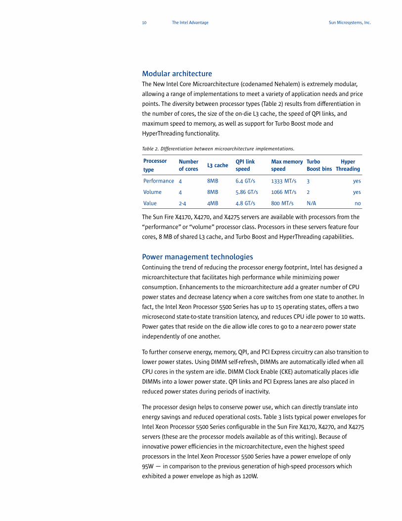
Modular architectureThe New Intel Core Microarchitecture (codenamed Nehalem) is extremely modular,
allowing a range of implementations to meet a variety of application needs and price
points. The diversity between processor types (Table 2) results from differentiation in
the number of cores, the size of the on-die L3 cache, the speed of QPI links, and
maximum speed to memory, as well as support for Turbo Boost mode and
HyperThreading functionality.
Table 2. DIfferentiation between microarchitecture implementations.
The Sun Fire X4170, X4270, and X4275 servers are available with processors from the
“performance” or “volume” processor class. Processors in these servers feature four
cores, 8 MB of shared L3 cache, and Turbo Boost and HyperThreading capabilities.
Power management technologiesContinuing the trend of reducing the processor energy footprint, Intel has designed a
microarchitecture that facilitates high performance while minimizing power
consumption. Enhancements to the microarchitecture add a greater number of CPU
power states and decrease latency when a core switches from one state to another. In
fact, the Intel Xeon Processor 5500 Series has up to 15 operating states, offers a two
microsecond state-to-state transition latency, and reduces CPU idle power to 10 watts.
Power gates that reside on the die allow idle cores to go to a near-zero power state
independently of one another.
To further conserve energy, memory, QPI, and PCI Express circuitry can also transition to
lower power states. Using DIMM self-refresh, DIMMs are automatically idled when all
CPU cores in the system are idle. DIMM Clock Enable (CKE) automatically places idle
DIMMs into a lower power state. QPI links and PCI Express lanes are also placed in
reduced power states during periods of inactivity.
The processor design helps to conserve power use, which can directly translate into
energy savings and reduced operational costs. Table 3 lists typical power envelopes for
Intel Xeon Processor 5500 Series configurable in the Sun Fire X4170, X4270, and X4275
servers (these are the processor models available as of this writing). Because of
innovative power efficiencies in the microarchitecture, even the highest speed
processors in the Intel Xeon Processor 5500 Series have a power envelope of only
95W — in comparison to the previous generation of high-speed processors which
exhibited a power envelope as high as 120W.
Processor
type
Number of cores
L3 cacheQPI link speed
Max memory speed
Turbo Boost bins
Hyper Threading
Performance 4 8MB 6.4 GT/s 1333 MT/s 3 yes
Volume 4 8MB 5.86 GT/s 1066 MT/s 2 yes
Value 2-4 4MB 4.8 GT/s 800 MT/s N/A no
11 The Intel Advantage Sun Microsystems, Inc.
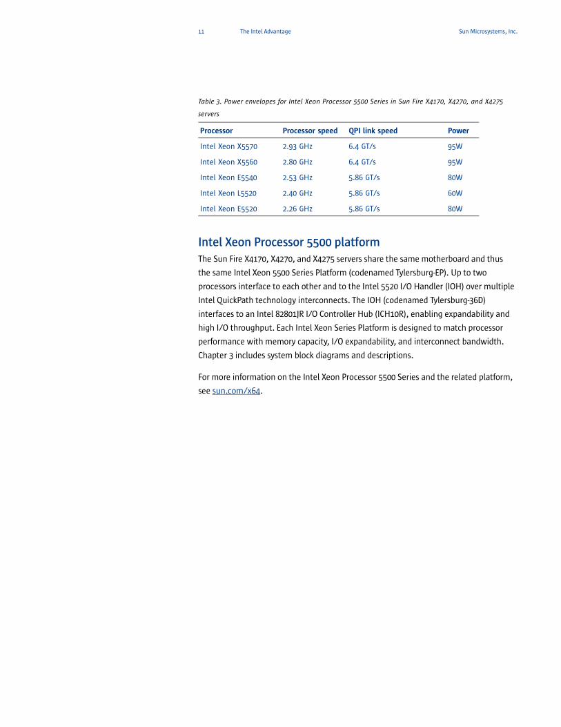
Table 3. Power envelopes for Intel Xeon Processor 5500 Series in Sun Fire X4170, X4270, and X4275
servers
Intel Xeon Processor 5500 platformThe Sun Fire X4170, X4270, and X4275 servers share the same motherboard and thus
the same Intel Xeon 5500 Series Platform (codenamed Tylersburg-EP). Up to two
processors interface to each other and to the Intel 5520 I/O Handler (IOH) over multiple
Intel QuickPath technology interconnects. The IOH (codenamed Tylersburg-36D)
interfaces to an Intel 82801JR I/O Controller Hub (ICH10R), enabling expandability and
high I/O throughput. Each Intel Xeon Series Platform is designed to match processor
performance with memory capacity, I/O expandability, and interconnect bandwidth.
Chapter 3 includes system block diagrams and descriptions.
For more information on the Intel Xeon Processor 5500 Series and the related platform,
see sun.com/x64.
Processor Processor speed QPI link speed Power
Intel Xeon X5570 2.93 GHz 6.4 GT/s 95W
Intel Xeon X5560 2.80 GHz 6.4 GT/s 95W
Intel Xeon E5540 2.53 GHz 5.86 GT/s 80W
Intel Xeon L5520 2.40 GHz 5.86 GT/s 60W
Intel Xeon E5520 2.26 GHz 5.86 GT/s 80W
12 Sun Fire X4170, X4270, and X4275 Server Architectures Sun Microsystems, Inc.
Chapter 3
Sun Fire X4170, X4270, and X4275 Server Architectures
The Sun Fire X4170, X4270, and X4275 servers are designed to provide best-in-class
performance with unprecedented expandability and low power consumption. This
chapter details physical and architectural aspects of the systems, highlighting
similarities and differences between the server designs.
The three server models share a common motherboard architecture — up to two Intel
Xeon Processor 5500 Series connect to an Intel 5520 I/O Handler (IOH) over multiple
Intel QuickPath technology interconnects. The IOH provides PCI 2.0 expandability and
interfaces to an Intel 82801JR I/O Controller Hub (ICH10R). Details about server
subsystems (chipsets, memory subsystems, I/O subsystems, etc.) are given later in
this chapter.
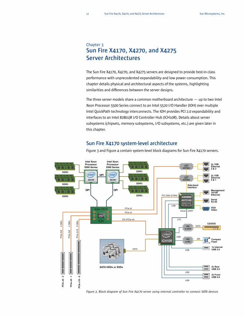
Sun Fire X4170 system-level architecture Figure 3 and Figure 4 contain system-level block diagrams for Sun Fire X4170 servers.
Figure 3. Block diagram of Sun Fire X4170 server using internal controller to connect SATA devices
PCIe
x8
- 2
PC
Ie 2
x84
GB
/s
PC
Ie 2
x84
GB
/s
PC
Ie 2
x16
8 G
B/s
PCIe
x8
- 1
PCIe
x16
- 0
82575EB
PCI 32bit 33 MHz
2x RearUSB 2.0
1x InternalUSB 2.0
CD/DVD
Compact Flash
2x FrontUSB 2.0
2x 1GBEthernet2 & 3
2x 1GBEthernet0 & 1
SerialRJ-45
Management10/100Ethernet
VGAVideo
USBto IDE
USBto SATA
82575EBU
SB
SATA
IDE
USB
USB
USB
USB
PCIe x2
PCIe x2
ESI (PCIe x4)
DDR3
DDR3
DDR3
DDR3
DDR3
DDR3
ICH10RICH10R
Intel XeonProcessor
5500 Series
Intel XeonProcessor
5500 Series
QPIQPI
QPIQPI QPIQPI
IOH IOH
Intel 5520 Intel 5520
XEONTM XEONTM
USB
LPC
Virtual UART
SATA
SATA HDDs or SSDs
AST2100G66925.1S-2E
4207 TAN GPA1
Side-bandInterface
13 Sun Fire X4170, X4270, and X4275 Server Architectures Sun Microsystems, Inc.
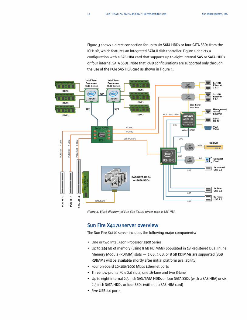
Figure 3 shows a direct connection for up to six SATA HDDs or four SATA SSDs from the
ICH10R, which features an integrated SATA-II disk controller. Figure 4 depicts a
configuration with a SAS HBA card that supports up to eight internal SAS or SATA HDDs
or four internal SATA SSDs. Note that RAID configurations are supported only through
the use of the PCIe SAS HBA card as shown in Figure 4.
Figure 4. Block diagram of Sun Fire X4170 server with a SAS HBA
Sun Fire X4170 server overviewThe Sun Fire X4170 server includes the following major components:
• One or two Intel Xeon Processor 5500 Series
• Up to 144 GB of memory (using 8 GB RDIMMs) populated in 18 Registered Dual Inline
Memory Module (RDIMM) slots — 2 GB, 4 GB, or 8 GB RDIMMs are supported (8GB
RDIMMs will be available shortly after initial platform availability)
• Four on-board 10/100/1000 Mbps Ethernet ports
• Three low-profile PCIe 2.0 slots, one 16-lane and two 8-lane
• Up to eight internal 2.5-inch SAS/SATA HDDs or four SATA SSDs (with a SAS HBA) or six
2.5-inch SATA HDDs or four SSDs (without a SAS HBA card)
• Five USB 2.0 ports
82575EB
PCIe
x8
- 2
PC
Ie 2
x84
GB
/s
PC
Ie 2
x84
GB
/s
PC
Ie 2
x16
8 G
B/s
PCI 32bit 33 MHz
PCIe
x8
- 1
PCIe
x16
- 0
2x RearUSB 2.0
1x InternalUSB 2.0
CD/DVD
Compact Flash
2x FrontUSB 2.0
2x 1GBEthernet2 & 3
2x 1GBEthernet0 & 1
SerialRJ-45
Management10/100Ethernet
VGAVideo
USBto IDE
USBto SATA
82575EB
US
B
SATA
IDE
USB
USB
USB
USB
PCIe x2
PCIe x2
ESI (PCIe x4)
DDR3
DDR3
DDR3
DDR3
DDR3
DDR3
ICH10RICH10R
Intel XeonProcessor
5500 Series
Intel XeonProcessor
5500 Series
QPIQPI
QPIQPI QPIQPI
IOH IOH
Intel 5520 Intel 5520
XEONTM XEONTM
USB
LPC
Virtual UART
SAS/SATA
SAS/SATA HDDs or SATA SSDs
PC
Ie S
AS
/RA
IDC
ontro
ller
AST2100G66925.1S-2E
4207 TAN GPA1
Side-bandInterface
14 Sun Fire X4170, X4270, and X4275 Server Architectures Sun Microsystems, Inc.
• An on-board ILOM service processor
• Up to two hot-swappable, high-efficiency power supply units (PSUs) for
N+1 redundancy
• Seven hot-swappable, variable speed fan modules (for N+1 redundancy), each
containing two fans operating under environmental monitoring
Sun Fire X4170 server enclosureThe Sun Fire X4170 server enclosure is designed to occupy one rack unit in a standard
19-inch rack. Table 4 gives system dimensions and weight.
Table 4. Dimensions and weight of the Sun Fire X4170 server
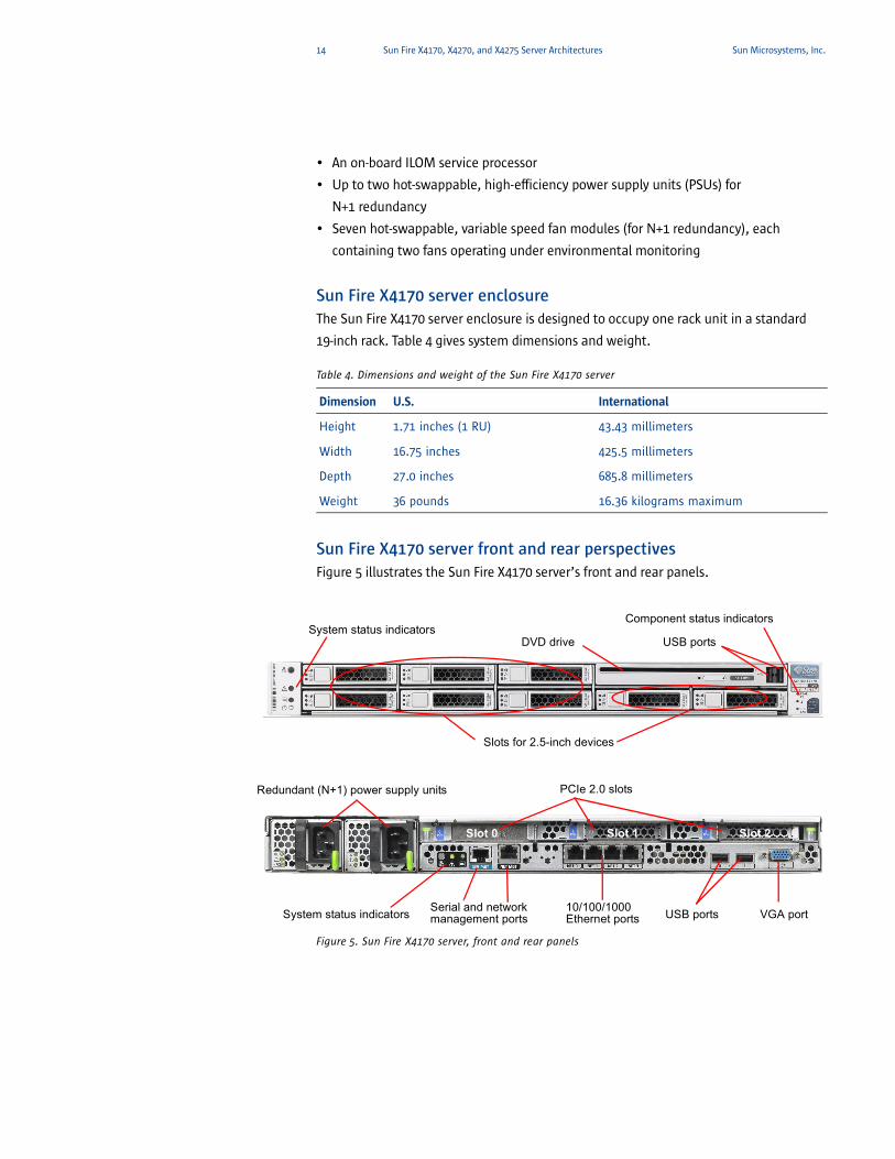
Sun Fire X4170 server front and rear perspectivesFigure 5 illustrates the Sun Fire X4170 server’s front and rear panels.
Figure 5. Sun Fire X4170 server, front and rear panels
Dimension U.S. International
Height 1.71 inches (1 RU) 43.43 millimeters
Width 16.75 inches 425.5 millimeters
Depth 27.0 inches 685.8 millimeters
Weight 36 pounds 16.36 kilograms maximum
System status indicators
Slots for 2.5-inch devices
DVD drive
Component status indicators
USB ports
Redundant (N+1) power supply units PCIe 2.0 slots
System status indicators 10/100/1000 Ethernet ports VGA portSerial and network
management ports USB ports
Slot 0 Slot 1 Slot 2
15 Sun Fire X4170, X4270, and X4275 Server Architectures Sun Microsystems, Inc.
External features and connections include:
• Front and rear status indicator lights, reporting “locator” (white), “service required”
(amber), and “activity status” (green) for the system and components
• Up to eight 2.5-inch SAS/SATA HDDs or four SATA SSDs (using a SAS HBA), or six 2.5-
inch SATA HDDs or four SATA SSDs (using the on-board controller) — all HDD or SSD
devices insert through the front panel
• One slimline, slot-accessible SATA DVD-RW, accessible through the front panel
• Five USB ports — two on the front panel, two on the rear panel, and one internal (to
attach internal boot devices)
• Up to two power supply units (for N+1 redundancy) with integrated fans, with each
power supply having a single, independent AC plug on the rear panel
• Rear power-supply indicator lights, showing the status of each hot-swappable
power supply
• Four 10/100/1000BaseT autosensing Ethernet ports, accessible on the rear panel
• Three PCIe 2.0 slots, in which low-profile cards can be installed from the rear panel
• Two management ports on the rear panel (one 10/100BaseT Ethernet port and one
RJ-45 serial port) for default connections to the service processor. Any one of the four
on-board Ethernet ports can also be configured as a system management port.
• VGA video port with an analog HD-15 VGA connector on the rear panel
16 Sun Fire X4170, X4270, and X4275 Server Architectures Sun Microsystems, Inc.
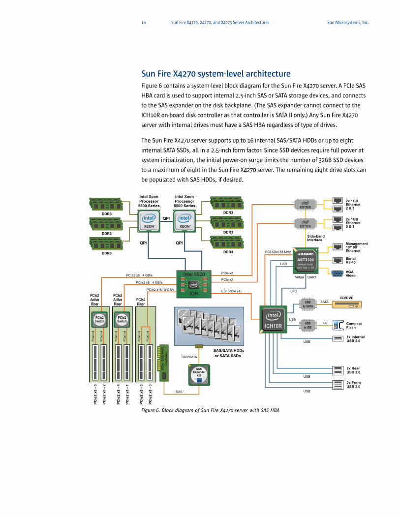
Sun Fire X4270 system-level architecture Figure 6 contains a system-level block diagram for the Sun Fire X4270 server. A PCIe SAS
HBA card is used to support internal 2.5-inch SAS or SATA storage devices, and connects
to the SAS expander on the disk backplane. (The SAS expander cannot connect to the
ICH10R on-board disk controller as that controller is SATA II only.) Any Sun Fire X4270
server with internal drives must have a SAS HBA regardless of type of drives.
The Sun Fire X4270 server supports up to 16 internal SAS/SATA HDDs or up to eight
internal SATA SSDs, all in a 2.5-inch form factor. Since SSD devices require full power at
system initialization, the initial power-on surge limits the number of 32GB SSD devices
to a maximum of eight in the Sun Fire X4270 server. The remaining eight drive slots can
be populated with SAS HDDs, if desired.
Figure 6. Block diagram of Sun Fire X4270 server with SAS HBA
82575EB
PCIe
2 x8
- 5
PCIe2 x8
PCIe
2 x8
PCIe
2 x8
PCIe
2 x8
PCIe
2 x8
PCIe
2 x8
PCIe
2 x8
4 GB/s
PCIe2 x8 4 GB/s
PCIe2 x16 8 GB/s
PCI 32bit 33 MHz
PCIe
2 x8
- 2
2x RearUSB 2.0
1x InternalUSB 2.0
CD/DVD
Compact Flash
2x FrontUSB 2.0
2x 1GBEthernet2 & 3
2x 1GBEthernet0 & 1
SerialRJ-45
Management10/100Ethernet
VGAVideo
USBto IDE
USBto SATA
82575EB
US
B
SATA
IDE
USB
USB
USB
USB
PCIe x2
PCIe x2
ESI (PCIe x4)
DDR3
DDR3
DDR3
DDR3
DDR3
DDR3
PCIe
2 x8
- 4
PCIe
2 x8
- 1
PCIe
2 x8
- 3
PCIe
2 x8
- 0
ICH10RICH10R
Intel XeonProcessor
5500 Series
Intel XeonProcessor
5500 Series
QPIQPI
QPIQPI QPIQPI
IOH IOH
Intel 5520 Intel 5520
XEONTM XEONTM
USB
LPC
Virtual UART
SAS
SAS/SATA
SAS/SATA HDDsor SATA SSDs
PC
Ie S
AS
/RA
IDC
ontro
ller
PCIe2Switch
PCIe2Switch
PCIe2 PCIe2 Active Active Riser Riser
PCIe2 PCIe2 Active Active Riser Riser
PCIe2 PCIe2 Riser Riser
AST2100G66925.1S-2E
4207 TAN GPA1
+ +
+ +SAS
Expanderx28
Side-bandInterface
17 Sun Fire X4170, X4270, and X4275 Server Architectures Sun Microsystems, Inc.
Sun Fire X4270 server overviewThe Sun Fire X4270 server includes the following major components:
• One or two Intel Xeon Processor 5500 Series
• Up to 144 GB of memory (using 8 GB RDIMMs) populated in 18 RDIMM slots — 2 GB,
4 GB, or 8 GB RDIMMs are supported (8GB RDIMMs will be available shortly after
initial platform availability)
• Up to sixteen internal 2.5-inch SAS/SATA HDDs or up to eight 2.5-inch SATA SSDs
(using a PCIe SAS HBA)
• Four on-board 10/100/1000 Mbps Ethernet ports
• Six low-profile PCIe 2.0 slots, all 8-lane
• Five USB 2.0 ports
• An on-board ILOM service processor
• Up to two hot-swappable, high-efficiency power supply units (PSUs) for
N+1 redundancy
• Six hot-swappable, variable speed fan modules (for N+1 redundancy), each with two
fans operating under environmental monitoring and control
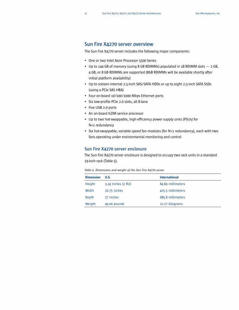
Sun Fire X4270 server enclosureThe Sun Fire X4270 server enclosure is designed to occupy two rack units in a standard
19-inch rack (Table 5).
Table 5. Dimensions and weight of the Sun Fire X4270 server
Dimension U.S. International
Height 3.34 inches (2 RU) 84.84 millimeters
Width 16.75 inches 425.5 millimeters
Depth 27 inches 685.8 millimeters
Weight 49.00 pounds 22.27 kilograms
18 Sun Fire X4170, X4270, and X4275 Server Architectures Sun Microsystems, Inc.
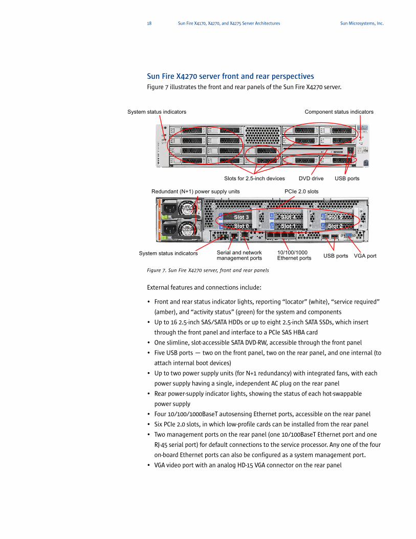
Sun Fire X4270 server front and rear perspectivesFigure 7 illustrates the front and rear panels of the Sun Fire X4270 server.
Figure 7. Sun Fire X4270 server, front and rear panels
External features and connections include:
• Front and rear status indicator lights, reporting “locator” (white), “service required”
(amber), and “activity status” (green) for the system and components
• Up to 16 2.5-inch SAS/SATA HDDs or up to eight 2.5-inch SATA SSDs, which insert
through the front panel and interface to a PCIe SAS HBA card
• One slimline, slot-accessible SATA DVD-RW, accessible through the front panel
• Five USB ports — two on the front panel, two on the rear panel, and one internal (to
attach internal boot devices)
• Up to two power supply units (for N+1 redundancy) with integrated fans, with each
power supply having a single, independent AC plug on the rear panel
• Rear power-supply indicator lights, showing the status of each hot-swappable
power supply
• Four 10/100/1000BaseT autosensing Ethernet ports, accessible on the rear panel
• Six PCIe 2.0 slots, in which low-profile cards can be installed from the rear panel
• Two management ports on the rear panel (one 10/100BaseT Ethernet port and one
RJ-45 serial port) for default connections to the service processor. Any one of the four
on-board Ethernet ports can also be configured as a system management port.
• VGA video port with an analog HD-15 VGA connector on the rear panel
System status indicators
Slots for 2.5-inch devices DVD drive
Component status indicators
USB ports
Redundant (N+1) power supply units PCIe 2.0 slots
System status indicators 10/100/1000 Ethernet ports VGA portSerial and network
management ports USB ports
Slot 3Slot 0
Slot 4Slot 1
Slot 5Slot 2
19 Sun Fire X4170, X4270, and X4275 Server Architectures Sun Microsystems, Inc.
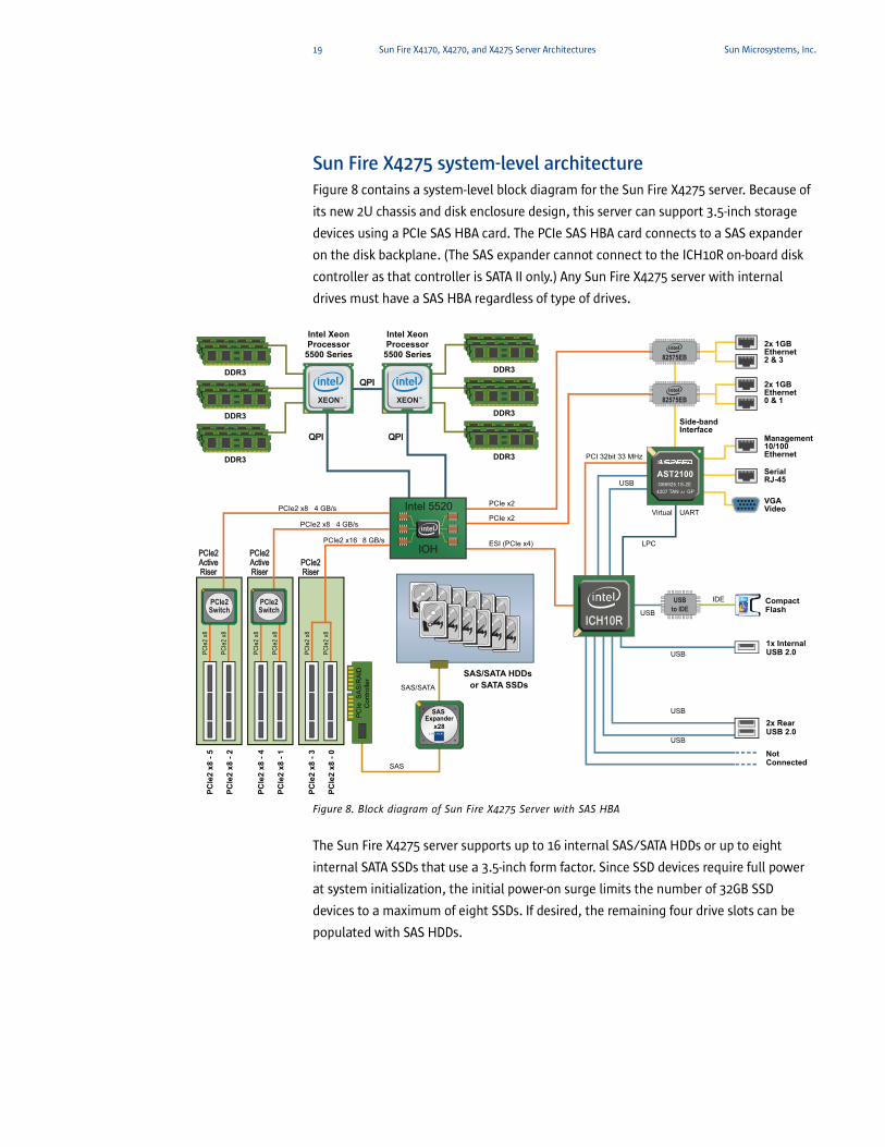
Sun Fire X4275 system-level architecture Figure 8 contains a system-level block diagram for the Sun Fire X4275 server. Because of
its new 2U chassis and disk enclosure design, this server can support 3.5-inch storage
devices using a PCIe SAS HBA card. The PCIe SAS HBA card connects to a SAS expander
on the disk backplane. (The SAS expander cannot connect to the ICH10R on-board disk
controller as that controller is SATA II only.) Any Sun Fire X4275 server with internal
drives must have a SAS HBA regardless of type of drives.
Figure 8. Block diagram of Sun Fire X4275 Server with SAS HBA
The Sun Fire X4275 server supports up to 16 internal SAS/SATA HDDs or up to eight
internal SATA SSDs that use a 3.5-inch form factor. Since SSD devices require full power
at system initialization, the initial power-on surge limits the number of 32GB SSD
devices to a maximum of eight SSDs. If desired, the remaining four drive slots can be
populated with SAS HDDs.
82575EB
PCIe
2 x8
- 5
PCIe2 x8
PCIe
2 x8
PCIe
2 x8
PCIe
2 x8
PCIe
2 x8
PCIe
2 x8
PCIe
2 x8
4 GB/s
PCIe2 x8 4 GB/s
PCIe2 x16 8 GB/s
PCI 32bit 33 MHz
PCIe
2 x8
- 2
2x RearUSB 2.0
NotConnected
1x InternalUSB 2.0
Compact Flash
2x 1GBEthernet2 & 3
2x 1GBEthernet0 & 1
SerialRJ-45
Management10/100Ethernet
VGAVideo
USBto IDE
82575EB
US
BIDE
USB
USB
USB
USB
PCIe x2
PCIe x2
ESI (PCIe x4)
DDR3
DDR3
DDR3
DDR3
DDR3
DDR3
PCIe
2 x8
- 4
PCIe
2 x8
- 1
PCIe
2 x8
- 3
PCIe
2 x8
- 0
ICH10RICH10R
Intel XeonProcessor
5500 Series
Intel XeonProcessor
5500 Series
QPIQPI
QPIQPI QPIQPI
IOH IOH
Intel 5520 Intel 5520
XEONTM XEONTM
USB
LPC
Virtual UART
SAS
SAS/SATA
SAS/SATA HDDs or SATA SSDs
PC
Ie S
AS
/RA
IDC
ontro
ller
PCIe2Switch
PCIe2Switch
PCIe2 PCIe2 Active Active Riser Riser
PCIe2 PCIe2 Active Active Riser Riser
PCIe2 PCIe2 Riser Riser
AST2100G66925.1S-2E
4207 TAN GPA1
+ +
+ +SAS Expander
x28
Side-bandInterface
20 Sun Fire X4170, X4270, and X4275 Server Architectures Sun Microsystems, Inc.
Sun Fire X4275 server overviewThe Sun Fire X4275 server includes the following major components:
• One or two Intel Xeon Processor 5500 Series
• Up to 144 GB of memory (using 8 GB RDIMMs) populated in 18 RDIMM slots — 2 GB,
4 GB, or 8 GB RDIMMs are supported (8GB RDIMMs will be available shortly after
initial platform availability)
• Up to 12 internal 3.5-inch SAS/SATA HDDs or eight SATA SSDs (using a PCIe SAS HBA)
• Four on-board 10/100/1000 Mbps Ethernet ports
• Six low-profile PCIe 2.0 slots, all 8-lane
• Three USB 2.0 ports
• An on-board ILOM service processor
• Up to two hot-swappable, high-efficiency power supply units (PSUs) for
N+1 redundancy
• Six hot-swappable, variable speed fan modules (for N+1 redundancy), each with two
fans operating under environmental monitoring and control
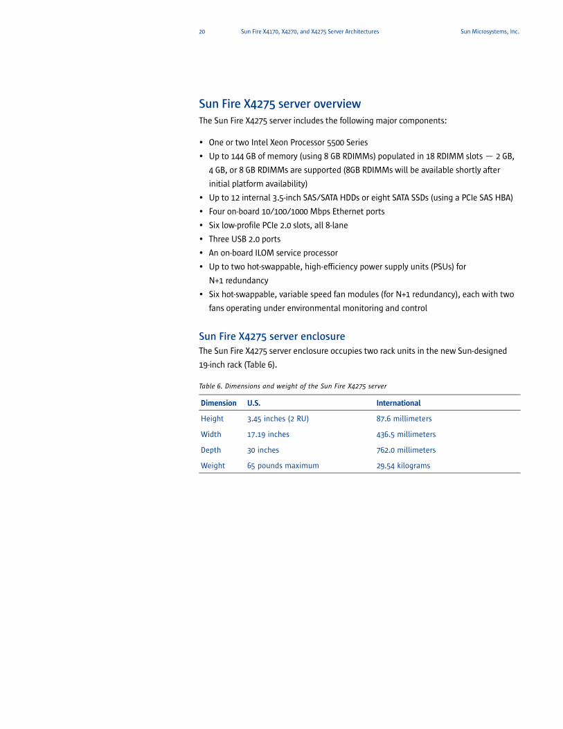
Sun Fire X4275 server enclosureThe Sun Fire X4275 server enclosure occupies two rack units in the new Sun-designed
19-inch rack (Table 6).
Table 6. Dimensions and weight of the Sun Fire X4275 server
Dimension U.S. International
Height 3.45 inches (2 RU) 87.6 millimeters
Width 17.19 inches 436.5 millimeters
Depth 30 inches 762.0 millimeters
Weight 65 pounds maximum 29.54 kilograms
21 Sun Fire X4170, X4270, and X4275 Server Architectures Sun Microsystems, Inc.
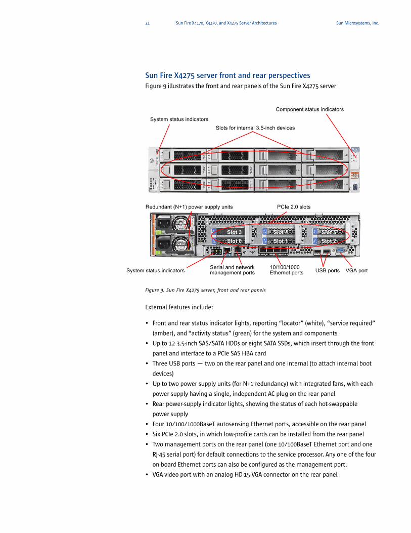
Sun Fire X4275 server front and rear perspectivesFigure 9 illustrates the front and rear panels of the Sun Fire X4275 server
Figure 9. Sun Fire X4275 server, front and rear panels
External features include:
• Front and rear status indicator lights, reporting “locator” (white), “service required”
(amber), and “activity status” (green) for the system and components
• Up to 12 3.5-inch SAS/SATA HDDs or eight SATA SSDs, which insert through the front
panel and interface to a PCIe SAS HBA card
• Three USB ports — two on the rear panel and one internal (to attach internal boot
devices)
• Up to two power supply units (for N+1 redundancy) with integrated fans, with each
power supply having a single, independent AC plug on the rear panel
• Rear power-supply indicator lights, showing the status of each hot-swappable
power supply
• Four 10/100/1000BaseT autosensing Ethernet ports, accessible on the rear panel
• Six PCIe 2.0 slots, in which low-profile cards can be installed from the rear panel
• Two management ports on the rear panel (one 10/100BaseT Ethernet port and one
RJ-45 serial port) for default connections to the service processor. Any one of the four
on-board Ethernet ports can also be configured as the management port.
• VGA video port with an analog HD-15 VGA connector on the rear panel
System status indicatorsSlots for internal 3.5-inch devices
Component status indicators
Redundant (N+1) power supply units PCIe 2.0 slots
System status indicators 10/100/1000 Ethernet ports VGA portSerial and network
management ports USB ports
Slot 3Slot 0
Slot 4Slot 1
Slot 5Slot 2
22 Sun Fire X4170, X4270, and X4275 Server Architectures Sun Microsystems, Inc.
System platformRefer back to the block diagrams earlier in this chapter. The Sun Fire X4170, X4270, and
X4275 servers are based on the Intel Xeon Processor 5500 Series platform,
which includes:
• Intel Xeon Processor 5500 Series. The Sun Fire X4170, X4270, and X4275 server
motherboard includes two processor sockets. (Chapter 2 describes the processor
microarchitecture.)
• An Intel 5520 I/O Handler (IOH). The IOH (codenamed Tylersburg-36D) features two
QuickPath interconnects and 36 PCIe 2.0 lanes. Of the 36 PCIe 2.0 lanes, 32 connect to
PCIe risers to enable PCIe 2.0 expandability. The remaining four lanes connect to two
Intel® 82575EB Gigabit Ethernet (Zoar) Controllers to support the four on-board
Ethernet ports.
• An Intel 82801JR I/O Controller Hub (ICH10R). The ICH10R is interconnected to the
IOH using one ESI (Enterprise South Bridge Interface) link. The ESI link is based on a
4-lane PCIe interconnect with proprietary extensions and offers a 2 GB/sec transfer
rate. The ICH10R enables additional I/O functionality including support for system
USB ports, the internal compact flash slot, and the SATA DVD/RW device (available on
the Sun Fire X4170 and X4270 servers only). The ICH10R connects to the Aspeed
AST2100 Service Processor using USB (for virtual devices), PCI (for video), and LPC
(serial port).
For more information on the Intel Xeon Processor 5500 Series chipset, see sun.com/x64.
Memory subsystemThe integrated memory controller and multiple DDR3 memory channels per processor
help to provide high bandwidth for memory-intensive applications. DDR3 memory
components offer greater density and run at higher speeds, but at significantly lower
voltages than previous generation DDR2 memories. The Sun Fire X4170, X4270, and
X4275 servers can be populated with DDR3 Registered ECC DIMM modules in either
2 GB, 4 GB, or 8 GB capacities. (8GB RDIMMS will be available shortly after the initial
release of the servers.)
Each processor features an integrated memory controller, which means that the
systems adhere to a Non-Uniform Memory Access (NUMA) memory architecture — the
memory controller on one processor can access local memory as well as remote
memory. The integrated memory controller supports DDR3 memories in three speeds
— 800 MT/s, 1066 MT/s, and 1333 MT/s — although Sun only qualifies and offers
1066 MT/s and 1333 MT/s RDIMMs. When configuring system memory, it is important
to note that DIMMs may run at slower than individually rated speeds depending on the
CPU type, the number of DIMMs per channel, and the type of memory (speed, rank,
23 Sun Fire X4170, X4270, and X4275 Server Architectures Sun Microsystems, Inc.
etc.). The speed at which memory is actually running is set by system BIOS at start-up,
and all memory channels will run at the fastest common frequency.
Memory population guidelinesEach processor features three memory channels. Each channel supports three RDIMM
slots, enabling up to 18 RDIMMs per system in a fully populated system. Memory slots
in each channel are color-coded to simplify identification:
• Blue represents slot 0
• White represents slot 1
• Black represents slot 2
As a general rule to optimize memory performance, DIMMs should be populated in sets
of three, one per channel per CPU, starting with the slot furthest from the CPU socket
(in slot 0, the blue slot). Ideally each channel should be populated with equal capacity
DIMMs, and if possible, with the same number of identical DIMMs (which helps to
make memory performance more consistent). In a server with a single processor, the
DIMM slots next to the empty CPU socket should not be populated. In general, it is
better to populate quad rank (QR) DIMMs first, followed by dual rank (DR) DIMMs and/
or single rank (SR) DIMMs.1
Optimizing memory for bandwidth
Configurations with optimal memory bandwidth can be achieved using the
“Performance” class of Intel Xeon Processor 5500 Series (see Table 2 on page 10) and
memory components that run at 1333MT/s. To optimize a configuration for bandwidth,
populate one single rank (SR) or dual rank (DR) DDR3 1333 MT/s DIMM per channel (the
use of quad rank (QR) DIMMs limits the number of DIMMs per channel to two, and
restricts the maximum memory access speed to 1066 MT/s).
Optimizing memory for capacity
If three DIMMs per channel are populated to optimize for memory capacity, the
memory access speed is reduced to 800 MT/s, regardless of the type of DIMMs (1066
MT/s or 1333 MT/s,). For this reason, using 1066 MT/s DIMMs is recommended to
reduce the configuration cost. With all 18 slots populated using 8GB DIMMs, it is
possible to achieve a maximum system memory capacity of 144GB.
I/O subsystemWith built-in headroom to expand systems and scale applications, the Sun Fire X4170,
X4270, and X4275 servers feature expandability through a PCIe 2.0 expansion bus,
internal storage options, four on-board Intel Gigabit Network Interface Controllers
(NICs), and integrated USB capabilities.
1. “Rank” refers to the number of memory chips that a DIMM module has connected on any given data line. Sun offers only single rank (SR) and dual rank (DR) DIMMs at this time.

24 Sun Fire X4170, X4270, and X4275 Server Architectures Sun Microsystems, Inc.
As shown in the block diagrams for the systems, the ICH10R provides connectivity for
system USB ports, the internal compact flash, and the SATA DVD/RW device (available
in the Sun Fire X4170 and X4270 servers only). To enable USB 2.0 functionality on the
Sun Fire X4170, X4270, and X4275 servers, two USB ports go from the ICH10R to the rear
panel and one USB link is routed to the internal USB port. On the Sun Fire X4170 and
X4270 servers, two additional USB ports are routed from the ICH10R to the front panel.
The ICH10R drives a USB-to-IDE interface that supports an internal compact flash slot
(Sun offers a 16GB compact flash device as an optional boot device). The ICH10R also
includes a USB-to-SATA interface to connect the internal SATA DVD/RW drive on Sun
Fire X4170 and X4270 servers.
System network interfacesThe IOH has four PCIe lanes that interface to two Intel® 82575EB Gigabit Ethernet (Zoar)
Controllers. Each controller supports two on-board 10/100/1000 Mbit/sec Ethernet
ports. Multiple on-board Gigabit Ethernet connections promote flexibility and enable
configurations that support network interface failover.
The four Gigabit Ethernet ports are numbered in sequence from left to right on the rear
panel. Each port auto-negotiates its link connection, and LEDs above the port indicate
the speed of the established link (green signifies that the established link is 1000 Mbit/
sec). The Ethernet interfaces also support PXE boot for booting over the network.
A new feature in the Sun Fire X4170, X4270, and X4275 servers is the ability to configure
any one of the four on-board Ethernet ports for “side-band” management. (See “ILOM
Service Processor and System Management” on page 34.) When configured as a
management port, one of the on-board Ethernet interfaces has two MAC addresses and
requires two IP addresses (one for data and one for management).
Just like the AST2100 Service Processor on the motherboard, the two Intel 82575EB
Gigabit Ethernet controllers are powered from a “stand-by” power source from system
power supplies. Even when power to the server is lost or turned off, the side-band
management interface remains active to allow remote management.
PCIe 2.0 expansion busThe Sun Fire X4170, X4270, and X4275 servers include a PCIe 2.0 expansion bus that can
accommodate low-profile cards rated at 25W maximum. PCIe 2.0 doubles the
interconnect bit rate, increasing the aggregated bi-directional bandwidth of a 16-lane
link to approximately 16 GB/s. On each server model, three right-angle risers plug
directly into the motherboard to enable PCI 2.0 expansion. Single slot 1U risers are used
on the Sun Fire X4170 server versus dual-slot 2U risers on the Sun Fire X4270 and
X4275 servers. Cards can be compliant with Revision 1.0a or 2.0 of the PCIe Card
Electromechanical Specification, and are installed with a horizontal orientation.
25 Sun Fire X4170, X4270, and X4275 Server Architectures Sun Microsystems, Inc.
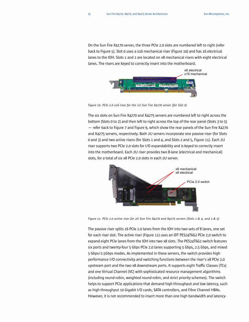
On the Sun Fire X4170 server, the three PCIe 2.0 slots are numbered left to right (refer
back to Figure 5). Slot 0 uses a x16 mechanical riser (Figure 10) and has 16 electrical
lanes to the IOH. Slots 1 and 2 are located on x8 mechanical risers with eight electrical
lanes. The risers are keyed to correctly insert into the motherboard.
Figure 10. PCIe 2.0 x16 riser for the 1U Sun Fire X4170 server (for Slot 0)
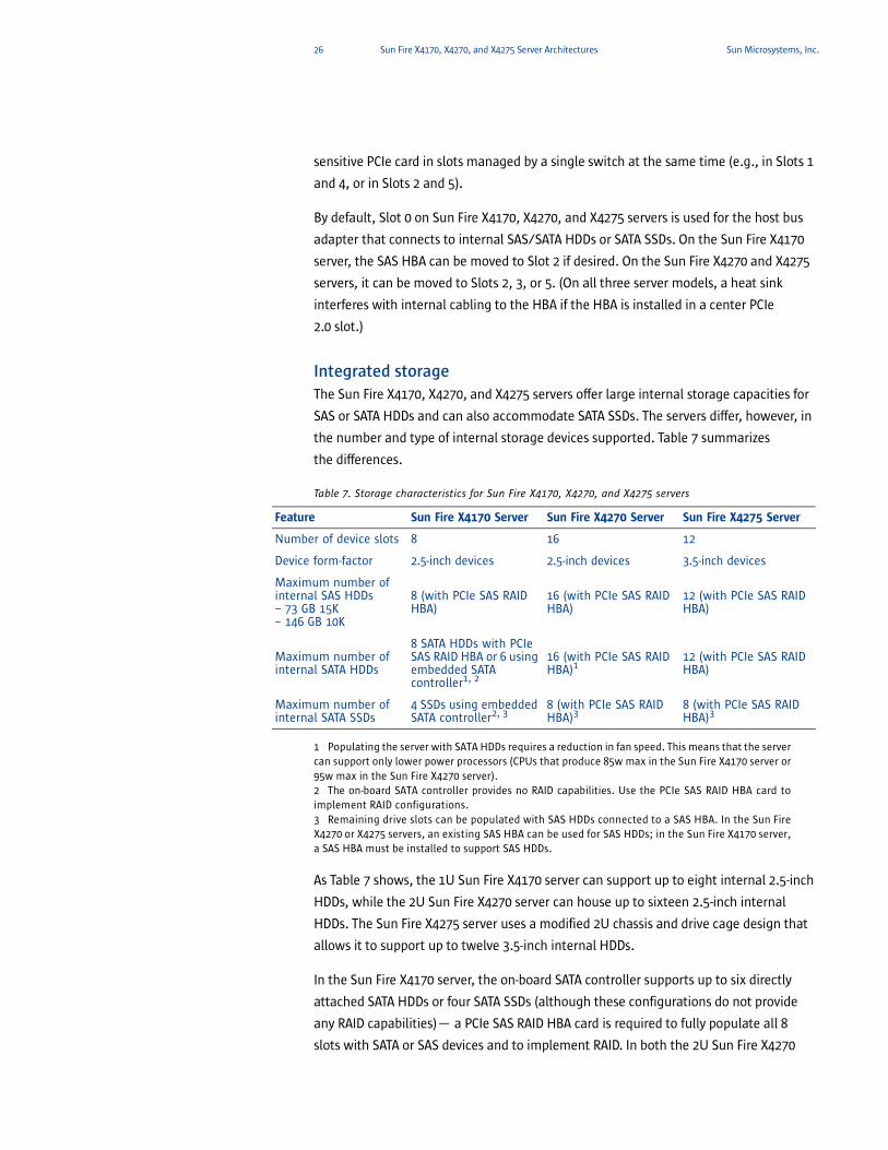
The six slots on Sun Fire X4270 and X4275 servers are numbered left to right across the
bottom (Slots 0 to 2) and then left to right across the top of the rear panel (Slots 3 to 5)
— refer back to Figure 7 and Figure 9, which show the rear panels of the Sun Fire X4270
and X4275 servers, respectively. Both 2U servers incorporate one passive riser (for Slots
0 and 3) and two active risers (for Slots 1 and 4, and Slots 2 and 5, Figure 11). Each 2U
riser supports two PCIe 2.0 slots for I/O expandability and is keyed to correctly insert
into the motherboard. Each 2U riser provides two 8-lane (electrical and mechanical)
slots, for a total of six x8 PCIe 2.0 slots in each 2U server.
Figure 11. PCIe 2.0 active riser for 2U Sun Fire X4270 and X4275 servers (Slots 1 & 4, and 2 & 5)
The passive riser splits 16 PCIe 2.0 lanes from the IOH into two sets of 8 lanes, one set
for each riser slot. The active riser (Figure 11) uses an IDT PES24T6G2 PCIe 2.0 switch to
expand eight PCIe lanes from the IOH into two x8 slots. The PES24T6G2 switch features
six ports and twenty-four 5 Gbps PCIe 2.0 lanes supporting 5 Gbps, 2.5 Gbps, and mixed
5 Gbps/2.5Gbps modes. As implemented in these servers, the switch provides high-
performance I/O connectivity and switching functions between the riser’s x8 PCIe 2.0
upstream port and the two x8 downstream ports. It supports eight Traffic Classes (TCs)
and one Virtual Channel (VC) with sophisticated resource management algorithms
(including round robin, weighted round-robin, and strict priority schemes). The switch
helps to support PCIe applications that demand high throughput and low latency, such
as high throughput 10 Gigabit I/O cards, SATA controllers, and Fibre Channel HBAs.
However, it is not recommended to insert more than one high bandwidth and latency-
x8 electricalx16 mechanical
x8 mechanicalx8 electrical
PCIe 2.0 switch
26 Sun Fire X4170, X4270, and X4275 Server Architectures Sun Microsystems, Inc.
sensitive PCIe card in slots managed by a single switch at the same time (e.g., in Slots 1
and 4, or in Slots 2 and 5).
By default, Slot 0 on Sun Fire X4170, X4270, and X4275 servers is used for the host bus
adapter that connects to internal SAS/SATA HDDs or SATA SSDs. On the Sun Fire X4170
server, the SAS HBA can be moved to Slot 2 if desired. On the Sun Fire X4270 and X4275
servers, it can be moved to Slots 2, 3, or 5. (On all three server models, a heat sink
interferes with internal cabling to the HBA if the HBA is installed in a center PCIe
2.0 slot.)
Integrated storageThe Sun Fire X4170, X4270, and X4275 servers offer large internal storage capacities for
SAS or SATA HDDs and can also accommodate SATA SSDs. The servers differ, however, in
the number and type of internal storage devices supported. Table 7 summarizes
the differences.
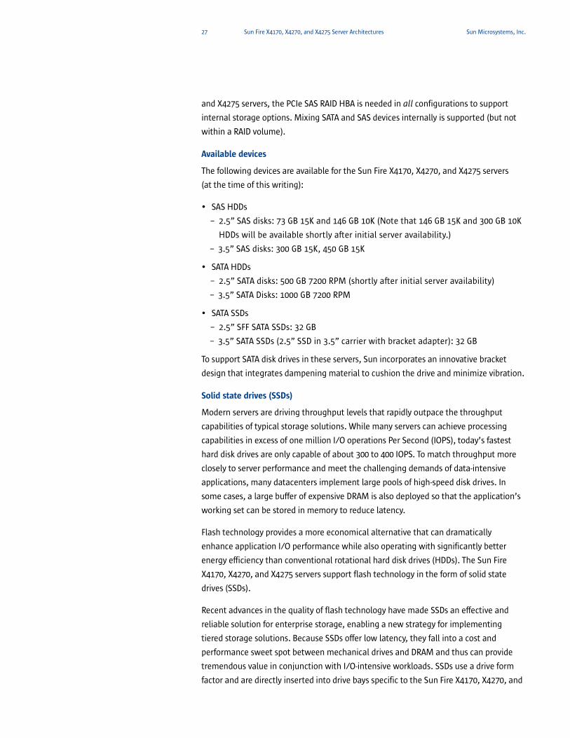
Table 7. Storage characteristics for Sun Fire X4170, X4270, and X4275 servers
1 Populating the server with SATA HDDs requires a reduction in fan speed. This means that the server can support only lower power processors (CPUs that produce 85w max in the Sun Fire X4170 server or 95w max in the Sun Fire X4270 server).2 The on-board SATA controller provides no RAID capabilities. Use the PCIe SAS RAID HBA card to implement RAID configurations.3 Remaining drive slots can be populated with SAS HDDs connected to a SAS HBA. In the Sun Fire X4270 or X4275 servers, an existing SAS HBA can be used for SAS HDDs; in the Sun Fire X4170 server, a SAS HBA must be installed to support SAS HDDs.
As Table 7 shows, the 1U Sun Fire X4170 server can support up to eight internal 2.5-inch
HDDs, while the 2U Sun Fire X4270 server can house up to sixteen 2.5-inch internal
HDDs. The Sun Fire X4275 server uses a modified 2U chassis and drive cage design that
allows it to support up to twelve 3.5-inch internal HDDs.
In the Sun Fire X4170 server, the on-board SATA controller supports up to six directly
attached SATA HDDs or four SATA SSDs (although these configurations do not provide
any RAID capabilities)— a PCIe SAS RAID HBA card is required to fully populate all 8
slots with SATA or SAS devices and to implement RAID. In both the 2U Sun Fire X4270
Feature Sun Fire X4170 Server Sun Fire X4270 Server Sun Fire X4275 Server
Number of device slots 8 16 12
Device form-factor 2.5-inch devices 2.5-inch devices 3.5-inch devices
Maximum number of internal SAS HDDs – 73 GB 15K– 146 GB 10K
8 (with PCIe SAS RAID HBA)
16 (with PCIe SAS RAID HBA)
12 (with PCIe SAS RAID HBA)
Maximum number of internal SATA HDDs
8 SATA HDDs with PCIe SAS RAID HBA or 6 using embedded SATA controller1, 2
16 (with PCIe SAS RAID HBA)1
12 (with PCIe SAS RAID HBA)
Maximum number of internal SATA SSDs
4 SSDs using embedded SATA controller2, 3
8 (with PCIe SAS RAID HBA)3
8 (with PCIe SAS RAID HBA)3
27 Sun Fire X4170, X4270, and X4275 Server Architectures Sun Microsystems, Inc.
and X4275 servers, the PCIe SAS RAID HBA is needed in all configurations to support
internal storage options. Mixing SATA and SAS devices internally is supported (but not
within a RAID volume).
Available devices
The following devices are available for the Sun Fire X4170, X4270, and X4275 servers
(at the time of this writing):
• SAS HDDs
– 2.5” SAS disks: 73 GB 15K and 146 GB 10K (Note that 146 GB 15K and 300 GB 10K
HDDs will be available shortly after initial server availability.)
– 3.5” SAS disks: 300 GB 15K, 450 GB 15K
• SATA HDDs
– 2.5” SATA disks: 500 GB 7200 RPM (shortly after initial server availability)
– 3.5” SATA Disks: 1000 GB 7200 RPM
• SATA SSDs
– 2.5” SFF SATA SSDs: 32 GB
– 3.5” SATA SSDs (2.5” SSD in 3.5” carrier with bracket adapter): 32 GB
To support SATA disk drives in these servers, Sun incorporates an innovative bracket
design that integrates dampening material to cushion the drive and minimize vibration.
Solid state drives (SSDs)
Modern servers are driving throughput levels that rapidly outpace the throughput
capabilities of typical storage solutions. While many servers can achieve processing
capabilities in excess of one million I/O operations Per Second (IOPS), today’s fastest
hard disk drives are only capable of about 300 to 400 IOPS. To match throughput more
closely to server performance and meet the challenging demands of data-intensive
applications, many datacenters implement large pools of high-speed disk drives. In
some cases, a large buffer of expensive DRAM is also deployed so that the application’s
working set can be stored in memory to reduce latency.
Flash technology provides a more economical alternative that can dramatically
enhance application I/O performance while also operating with significantly better
energy efficiency than conventional rotational hard disk drives (HDDs). The Sun Fire
X4170, X4270, and X4275 servers support flash technology in the form of solid state
drives (SSDs).
Recent advances in the quality of flash technology have made SSDs an effective and
reliable solution for enterprise storage, enabling a new strategy for implementing
tiered storage solutions. Because SSDs offer low latency, they fall into a cost and
performance sweet spot between mechanical drives and DRAM and thus can provide
tremendous value in conjunction with I/O-intensive workloads. SSDs use a drive form
factor and are directly inserted into drive bays specific to the Sun Fire X4170, X4270, and

28 Sun Fire X4170, X4270, and X4275 Server Architectures Sun Microsystems, Inc.
X4275 servers. The servers’ operating system and BIOS views SSDs as standard
SATA drives.
Unlike rotational media, which spins up slowly at power-on, SSD devices require full
power at system initialization. Because of this initial power-on surge, there are some
limitations with the number of 32GB SSD devices initially supported in the Sun Fire
X4170, X4270, and X4275 servers. The Sun Fire X4170 server can support a maximum of
four SATA SSDs, while the Sun Fire X4270 and X4275 servers can support a maximum of
eight SSD devices. For configurations that incorporate a SAS HBA, it is possible,
however, to populate remaining empty device slots with SAS HDDs.
Optimizing performance using SSDs
Taking advantage of the performance and cost characteristics of an SSD requires an
enabling technology that can transparently use it to drive better application and file
system performance. Solaris ZFS allows datacenter architects to balance performance
requirements against cost by using a variety of device types to store, archive, and
access information. Creating a Hybrid Storage Pool in Solaris ZFS leverages the
strengths of both rotational and solid state storage media. A Hybrid Storage Pool
automatically places data on the most appropriate storage media to optimize
performance and manage costs, and the ZFS file system can transparently cache data
on SSDs without any need to modify applications. ZFS recognizes different media types
and optimizes data placement to maximize system throughput. (For more information,
see the solution brief “Solaris ZFS Enables Hybrid Storage Pools — Shatters Economic
and Performance Barriers,” available at www.sun.com/software/solaris/pdf/
solariszfs_solutionbrief.pdf).
Sun Flash Analyzer
To simplify the adoption of flash technology, the Sun Flash Analyzer tool can be used to
detect I/O-intensive applications that can best benefit from the performance
advantages of using flash technology. The Sun Flash Analyzer tool runs on the Solaris
OS, Microsoft Windows, and Linux operating environments and can be downloaded
from sun.com/flash/resources.
For more information on flash technology in Sun products, see sun.com/flash.
Drive cage design
The ample storage density of the Sun Fire X4170, X4270, and X4275 servers is partly due
to innovative drive carrier designs that facilitate effective air flow above and below each
drive. Drives insert into a modular disk tray and cable-free disk backplane that increases
reliability and serviceability. The carrier includes an ejection handle that simplifies drive
removal — drives are hot-pluggable when disk mirroring is configured. Drive status
lights indicate “Ready to remove”, “Fault”, and “Status”.

29 Sun Fire X4170, X4270, and X4275 Server Architectures Sun Microsystems, Inc.
In all three systems, the disks plug into a server-specific backplane board. In the Sun
Fire X4270 and X4275 servers, a 28-port LSI SAS expander (the LSISASX28) facilitates
large internal storage capacities. On the Sun Fire X4270 server, eight ports on the SAS
expander connect to the SAS HBA, supporting switched connections for up to 16 SAS or
SATA devices. On the Sun Fire X4275 server, six ports on the SAS expander connect to
the HBA to support switched connections to up to 12 3.5-inch SAS or SATA devices.
Sun engineers modified the chassis of the Sun Fire X4275 server specifically to
accommodate support for larger 3.5-inch internal storage devices. On the Sun Fire
X4275 server, the SAS expander is located on a daughtercard (whereas it resides directly
on the backplane in the 2U Sun Fire X4270 server). Also, the drive cage in the Sun Fire
X4275 server is not removable. To minimize drive vibration for 3.5-inch devices, Sun
added dampening material to the Sun Fire X4275 server drive cage and designed the
fan deck with a floating spring mechanism that helps to isolate fan vibration.
Disk Controller and I/O RAID Options
The Sun Fire X4170, X4270, and X4275 servers support the following options for
disk controllers:
• Embedded SATA II controller on the motherboard (Sun Fire X4170 server only). This
controller supports up to six internal SATA HDDs or four SSDs (but it does not include
any RAID support).
• Sun StorageTek SAS HBA based on LSI chipset. A low-profile card, the external version
of this controller offers no RAID support and has two external 4-port SFF-8088
connectors. The internal version of this HBA has two internal 4-port SFF-8087
connectors and enables hardware RAID levels 0, 1, or 10.
• Sun StorageTek SAS RAID HBA, which supports 3 GB/sec SAS and hardware RAID levels
0, 1, 1E, 5, 5EE, 6, 10, 50, and 60. Based on Adaptec and Intel technology, this HBA is
an 8-channel, low-profile card with two 4-port SFF-8087 connectors. The card is
available in two versions: one with internal connectors and one with external
connectors. This HBA includes 256 MB of DDR2 memory on-board and a battery-
backed write cache for 72-hour backup, which helps to deliver protected, high
availability storage.
Two cables with four lanes (each at 3 Gb/sec) each are wired from the SAS adapter to
the disk backplane to control the internal HDD and SSD drives and provide high
bandwidth. For the Sun Fire X4170 server, the four SAS links from the HBA connect
directly to the SAS/SATA devices. In the case of the Sun Fire X4270 or X4275 server, the
four SAS links connect to the LSISASX28 SAS expander. The SAS expander then provides
connections to individual disks in the drive cage.
30 Sun Fire X4170, X4270, and X4275 Server Architectures Sun Microsystems, Inc.
DVD/USB Assembly
A slim form-factor SATA DVD/RW assembly is available as an option to the Sun Fire
X4170 and X4270 servers. The assembly provides an internal DVD-RW device as well as
two USB ports accessible from the front panel. A locking handle allows the assembly to
be safely secured and more easily extracted from the system chassis. Sun Fire X4170
and X4270 servers can also be ordered with an assembly that features two USB ports
only (and no DVD device). (Note that EIDE DVD devices used in previous servers are not
supported in the Sun Fire X4170 and X4270 servers since the new systems are designed
for a SATA DVD device. The new SATA DVD devices are clearly labeled “SATA” on the
device’s exterior.)
Enclosure featuresThe Sun Fire X4170, X4270, and X4275 servers feature innovative chassis designs
engineered to conserve system power and reduce cooling. The power and cooling
efficiency of these systems exceeds that of many competitive systems configured with
similar processing, memory, and storage capacities. The effective front-to-back airflow
design helps to lower component temperatures, reducing the number of fans needed to
cool the system. Processors also consume less energy under cooler temperatures, and
lower component temperatures help to increase overall reliability.
Key enclosure features include:
• Hex-shaped, honeycombed air inlet holes that enhance airflow and provide
EMI shielding
• Front-mounted fans (located directly behind the disk drive cage) that pull air through
the chassis, over system components, and exhaust it out the rear panel
• Innovative disk drive bracket design that enables efficient air flow above and below
drive units
• Cable and component placement that helps to optimize cooling efficiency by
channeling airflow effectively, as well as the reduction of internal cables to
enhance airflow
• Fewer DC-to-DC conversions to improve power efficiency and generate less heat
Power distributionEngineered for high availability as well as low energy consumption, the Sun Fire X4170,
X4270, and X4275 servers can be configured with two highly-efficient, redundant, hot-
swappable AC/DC power supply units (PSUs), each with separate power cords.
Configuring a system with a second power supply enables N+1 redundancy, supplying
continuous power to the system if a single power supply fails.
The PSUs differ between systems — the Sun Fire X4170 server uses 760W PSUs while
the Sun Fire X4270 and X4275 servers require 1050W PSUs. As shown in Table 8, the
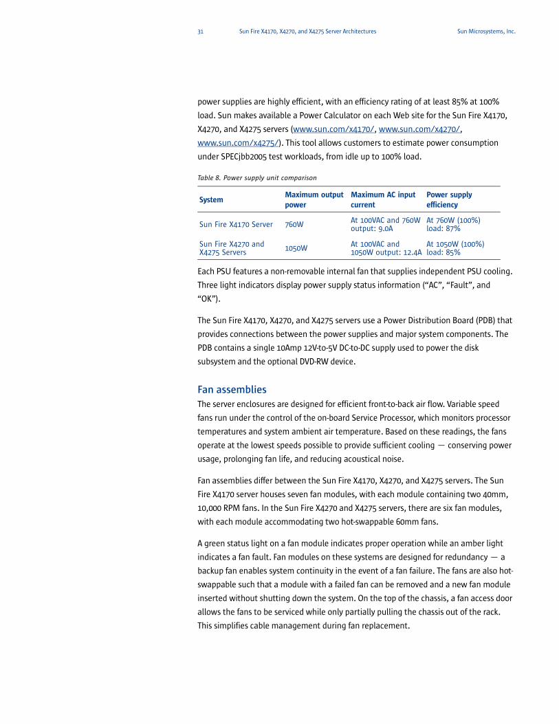
31 Sun Fire X4170, X4270, and X4275 Server Architectures Sun Microsystems, Inc.
power supplies are highly efficient, with an efficiency rating of at least 85% at 100%
load. Sun makes available a Power Calculator on each Web site for the Sun Fire X4170,
X4270, and X4275 servers (www.sun.com/x4170/, www.sun.com/x4270/,
www.sun.com/x4275/). This tool allows customers to estimate power consumption
under SPECjbb2005 test workloads, from idle up to 100% load.
Table 8. Power supply unit comparison
Each PSU features a non-removable internal fan that supplies independent PSU cooling.
Three light indicators display power supply status information (“AC”, “Fault”, and
“OK”).
The Sun Fire X4170, X4270, and X4275 servers use a Power Distribution Board (PDB) that
provides connections between the power supplies and major system components. The
PDB contains a single 10Amp 12V-to-5V DC-to-DC supply used to power the disk
subsystem and the optional DVD-RW device.
Fan assembliesThe server enclosures are designed for efficient front-to-back air flow. Variable speed
fans run under the control of the on-board Service Processor, which monitors processor
temperatures and system ambient air temperature. Based on these readings, the fans
operate at the lowest speeds possible to provide sufficient cooling — conserving power
usage, prolonging fan life, and reducing acoustical noise.
Fan assemblies differ between the Sun Fire X4170, X4270, and X4275 servers. The Sun
Fire X4170 server houses seven fan modules, with each module containing two 40mm,
10,000 RPM fans. In the Sun Fire X4270 and X4275 servers, there are six fan modules,
with each module accommodating two hot-swappable 60mm fans.
A green status light on a fan module indicates proper operation while an amber light
indicates a fan fault. Fan modules on these systems are designed for redundancy — a
backup fan enables system continuity in the event of a fan failure. The fans are also hot-
swappable such that a module with a failed fan can be removed and a new fan module
inserted without shutting down the system. On the top of the chassis, a fan access door
allows the fans to be serviced while only partially pulling the chassis out of the rack.
This simplifies cable management during fan replacement.
SystemMaximum output power
Maximum AC input current
Power supply efficiency
Sun Fire X4170 Server 760W At 100VAC and 760W output: 9.0A
At 760W (100%) load: 87%
Sun Fire X4270 and X4275 Servers 1050W At 100VAC and
1050W output: 12.4AAt 1050W (100%) load: 85%

32 Sun Fire X4170, X4270, and X4275 Server Architectures Sun Microsystems, Inc.
Rack mountingTo shorten time-to-deployment, the Sun Customer Ready Systems program can pre-
install Sun Fire X4170, X4270, and X4275 servers in a rack configuration. Alternatively,
these 1U and 2U servers can be field-installed into Sun or other third-party racks that
meet rack-mounting requirements.
The Sun Fire X4170 and X4270 servers can be mounted in these racks:
• Third Party ANSI/EIA-310-D-1992 or IEC 60927-compliant racks in 19-inch/482.6mm
panel-width series
• Sun Rack 938
• Sun Rack 1038 and 1042
• Sun Rack II 1042 and 1242
The Sun Fire X4275 server can be rack-mounted in the Sun Rack II 1242. It can also be
rack-mounted in the Sun Rack II 1042 (with some limitations due to the depth of the
chassis, particularly when using the cable management arm — see the documentation
for more details). As a part of its redesigned chassis, the Sun Fire X4275 server features
new slide rail release levers (refer back to Figure 9). Pulling down on these levers
unlocks the rails’ sliding mechanism, allowing the chassis to be pulled out of the rack
for easier servicing.
The following options are available to simplify rack mounting:
• Rack-Mounting Slide Rail Kit. This is a 4-point mounted slide rail kit (i.e., mounting
points are located at the rack front and rear).
• Tool-less Rack Kit. As the name implies, this rack-mounting kit snaps into certain Sun
and third-party racks without requiring any tools.
• Cable Management Arm. The cable management arm supports and protects cables
as the server slides in and out of the rack.
The Slide Rail Kit includes hardware to mount to rack rails with either 6mm threaded
holes, #10-32 threaded holes, #10 clearance holes, or square unthreaded holes per
ANSI/EIA 310-D-1992 or IEC 60927 standards. Note that not all third-party racks are
compatible with the slide rail kit. Rack density will vary widely based on systems
installed, power distribution (in-cabinet or external), power source (single-phase or
three-phase), and whether redundant power is required.
RAS featuresCorporate data and business information comprise critical business assets. Enterprise
computing technologies strive to furnish a high degree of data protection (reliability),
to provide virtually continuous application access (availability), and to incorporate
procedures and components that help to resolve problems with minimal business
impact (serviceability). Commonly referred to as RAS, these capabilities are a standard
part of Sun’s mission-critical computing solutions.

33 Sun Fire X4170, X4270, and X4275 Server Architectures Sun Microsystems, Inc.
The Sun Fire X4170, X4270, and X4275 servers are engineered for hardware failure
prevention, near continuous operation, fast recovery, and easy serviceability. RAS
features for these systems include:
• High CPU density. Multiple Intel Xeon processors in 1U and 2U form factors enable
density that increases overall availability.
• Hot-swappable redundant components. Mirrored disks, redundant fan modules, and
redundant PSUs can be quickly and easily changed out, increasing system uptime.
• Accessible components for improved serviceability. Front-accessible, hot-swappable
disk drives can be replaced quickly. The optional DVD/RW drive can also be removed
without opening the top cover of the chassis. Fan modules and power supply units
can be replaced without completely removing a system from the rack.
• A variety of RAID options, allowing customers to balance storage capacity,
availability, and cost. The LSI-based Sun StorageTek SAS HBA with internal connectors
supports RAID 0, 1, 1E, and 10E, while the Sun StorageTek SAS RAID host bus adapter
supports RAID 0, 1, 10, 1E, 5, 50, 5EE, 6, 60 and also features a battery-backed disk
write cache.
• Indicator LEDs on the front and back of the chassis. Easily visible LEDs allow problems
to be identified and isolated easily. Diagnostic LEDs are also included on the
motherboard.
• Integrated lights-out management (ILOM) capabilities. Standard on the Sun Fire
X4170, X4270, and X4275 servers at no additional charge, the integrated ILOM service
processor provides powerful tools for local or remote system management,
simplifying administrative tasks, reducing on-site personnel needed, and lowering
overall operational costs. (Chapter 4 discusses system management capabilities.)
34 ILOM Service Processor and System Management Sun Microsystems, Inc.
Chapter 4
ILOM Service Processor and System Management
The need for high availability in business-critical systems calls for robust and proactive
system management. Like many other Sun servers, the Sun Fire X4170, X4270, and
X4275 servers feature a built-in, hardware-based service processor that enables remote
server monitoring, system management, and task automation capabilities that are
consistent across much of the Sun server product line.
Sun ILOM service processorThe Sun Fire X4170, X4270, and X4275 servers embed an Aspeed AST2100 chip as the on-
board service processor (i.e., the Baseboard Management Controller or BMC). The
Aspeed AST2100 combines a graphics controller and a service processor into a single
chip, saving space and power. It uses two USB ports for virtual devices and one 32-bit,
33Mhz PCI bus for video to connect to the ICH10R (refer back to system block diagrams
in Chapter 3).
The Sun ILOM service processor provides lights-out management, which can help
organizations simplify system management. The service processor runs independently
of the host platform, executing a robust, security-hardened operating system.
Capabilities of the Sun ILOM service processor include the following:
• Full local and remote keyboard, video, mouse, and storage (RKVMS) access via
redirection over IP, eliminating the need for KVM switches
• Monitoring and reporting of environmental, power, hardware, BIOS, and operating
system events
• Remote power control, diagnostics, media attachment, and flash upgrades of the
system BIOS and service processor software
• System configuration information retrieval
• User configurable serial console access through a physical port or redirected over IP
• Java-enabled remote console access across a secure Web connection
• Multi-level role based access with support for RADIUS, LDAP, and Microsoft Active
Directory Service lookup of authentication data
• Simple Network Management Protocol (SNMP) V1, V2c, and V3 support
For system management operations, the Aspeed AST2100 uses these connections:
• Two USB ports for virtual devices (both ports are routed directly on the motherboard
between the AST2100 and the ICH10R)
• Two serial ports (one external, one to the ICH10R)
• Two Ethernet interfaces for IP-based management connections (one external for out-
of-band management, one to the Intel NIC controllers for side-band management)
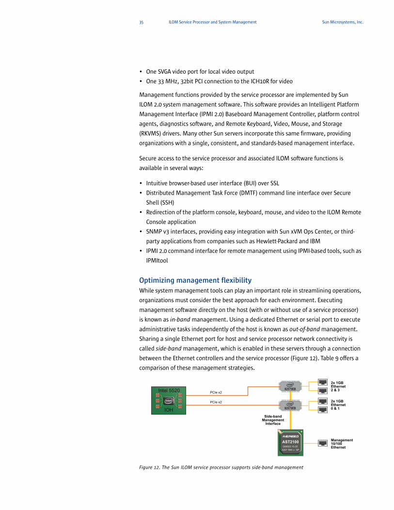
35 ILOM Service Processor and System Management Sun Microsystems, Inc.
• One SVGA video port for local video output
• One 33 MHz, 32bit PCI connection to the ICH10R for video
Management functions provided by the service processor are implemented by Sun
ILOM 2.0 system management software. This software provides an Intelligent Platform
Management Interface (IPMI 2.0) Baseboard Management Controller, platform control
agents, diagnostics software, and Remote Keyboard, Video, Mouse, and Storage
(RKVMS) drivers. Many other Sun servers incorporate this same firmware, providing
organizations with a single, consistent, and standards-based management interface.
Secure access to the service processor and associated ILOM software functions is
available in several ways:
• Intuitive browser-based user interface (BUI) over SSL
• Distributed Management Task Force (DMTF) command line interface over Secure
Shell (SSH)
• Redirection of the platform console, keyboard, mouse, and video to the ILOM Remote
Console application
• SNMP v3 interfaces, providing easy integration with Sun xVM Ops Center, or third-
party applications from companies such as Hewlett-Packard and IBM
• IPMI 2.0 command interface for remote management using IPMI-based tools, such as
IPMItool
Optimizing management flexibilityWhile system management tools can play an important role in streamlining operations,
organizations must consider the best approach for each environment. Executing
management software directly on the host (with or without use of a service processor)
is known as in-band management. Using a dedicated Ethernet or serial port to execute
administrative tasks independently of the host is known as out-of-band management.
Sharing a single Ethernet port for host and service processor network connectivity is
called side-band management, which is enabled in these servers through a connection
between the Ethernet controllers and the service processor (Figure 12). Table 9 offers a
comparison of these management strategies.
Figure 12. The Sun ILOM service processor supports side-band management
82575EB
2x 1GBEthernet2 & 3
2x 1GBEthernet0 & 1
Management10/100Ethernet
82575EBPCIe x2
PCIe x2
IOH IOH
Intel 5520 Intel 5520
AST2100G66925.1S-2E
4207 TAN GPA1
Side-bandManagement
Interface

36 ILOM Service Processor and System Management Sun Microsystems, Inc.
Table 9. Comparison of in-band, out-of-band, and side-band management
The Sun Fire X4170, X4270, and X4275 servers offer extensive flexibility by supporting all
three of these strategies — in-band, out-of-band, and side-band management.
Organizations can choose a single management method or use in-band management in
tandem with out-of-band or side-band management approaches.
The Sun Fire X4170, X4270, and X4275 servers provide out-of-band management across
a dedicated 10/100 Mb Ethernet port or an RS-232 serial port on the Sun ILOM service
processor. Side-band management is supported over one of the four Gigabit Ethernet
interfaces shared between both the host and the service processor. When using a side-
band management approach, both the platform and the service processor each get a
unique MAC address and IP address for the shared physical Ethernet port. When
configured, side-band management can provide all the benefits of out-of-band
management at considerable cost savings by eliminating the need to consume a switch
port for both management and platform connections.
In-band server management
In-band server management offers the opportunity for organizations to take advantage
of industry-standard protocols and applications across all datacenter platforms. The
Sun Fire X4170, X4270, and X4275 servers facilitate in-band server management by
Strategy Characteristics Benefits Ideal use cases
In-band Relies upon operating system-resident software
Management tasks utilize platform compute resources
Use of a single network connection and switch port minimizes cost and complexity
Heterogeneous environments with requirements to provide a common administrative tool across all platforms
Out-of-band Utilizes a dedicated Ethernet or serial port for administrative traffic
Management tasks execute on an independent service processor
Continuous access to management capabilities even when host is disabled
Management tasks do not consume host resources
Increased security by physically separating management traffic and server data
Environments with compute or bandwidth intensive applications
Projects with complex management requirements or high-levels of administrative burden
Side-band The host and service processor share an Ethernet port and are each assigned an independent MAC and IP address
Management tasks execute on an independent service processor
Continuous access to management capabilities even when host is disabled
Management traffic uses part of the server data bandwidth
Requires only one switch port, lowering implementation costs
Minimizes processing overhead on the host
Cost-sensitive environments
37 ILOM Service Processor and System Management Sun Microsystems, Inc.
supporting IPMI 2.0 and SNMP v1, v2c, and v3 standards. One of the following two
options enable these operating system-resident platform management functions:
• IPMI with a Keyboard Controller Style (KCS) interface and an IPMI kernel driver
• SNMP agents
Out-of-band and side-band management
Out-of-band and side-band management approaches support the completion of
administrative tasks without placing unnecessary burden on the host. This
administrative strategy is desirable for performance-intensive environments. While in-
band management only works as long as the host operating system is up and running,
out-of-band and side-band management are fully functional even while the host is
powered off. For side-band management to work even while the host is shut down, the
two dual-Gigabit Ethernet (Zoar) controllers operate using stand-by power, similar to
the service processor.
Although out-of-band and side-band approaches differ with respect to network
connectivity, these methods offer comparable capabilities and benefits.
• Based on serial port redirection (serial-over-LAN), serial port connectivity to the ILOM
Service Processor provides direct console access to the command line interface (CLI)
and to the system console stream. The CLI is designed to follow the Distributed
Management Task Force (DMTF) Command Line Protocol (CLP).
• Utilizing Ethernet connectivity, administrators can access a Web interface or
command-line interface (CLI). A secure shell (SSH) session is required for access to the
CLI and the Web interface supports both secure (https) and non-secure (http) access.
Secure access is the default configuration for Web-based access.
Remote keyboard, video, mouse, and storage (RKVMS)The ILOM Service Processor provides access to Keyboard, Video, Mouse, and Storage
(RKVMS) remotely over IP. Remote video display is accomplished through the Java™ Web
Start software known as Sun ILOM Remote Console. To set up a system as a remote
console, ILOM Remote Console software is downloaded from the ILOM service processor
to the target machine.2 From this point onward, the ILOM Remote Console executes
locally. Since ILOM Remote Console does not run locally on the server, it does not put
overhead on the host. A single instance of ILOM Remote Console can open multiple
sessions, enabling management of several remote servers simultaneously.
ILOM Remote Console software can be used to redirect the BIOS and setup screens as
well as all other platform video output. A true remote video console to the
management console is provided by handling the input and output to and from virtual
devices and the Sun Fire X4170, X4270, and X4275 servers. With 8-bit and 16-bit
support, 8 MB of video memory, the SVGA display provide resolutions up to 1280 x 1024.
ole.
2. ILOM Remote Console requires the installation of Java Runtime Environment 5.0 on the management cons
38 ILOM Service Processor and System Management Sun Microsystems, Inc.
The two USB 2.0 ports connected to the ILOM service processor enable the remote
keyboard, mouse and storage functions. The ILOM Remote Console software captures
keyboard, mouse and floppy/CD/DVD input on the management console and redirects
it over IP to the ILOM service processor. Keyboard, mouse and storage inputs are then
transmitted over the USB ports to the server. The Sun Fire X4170, X4270, and X4275
servers interpret these inputs as originating from locally connected USB devices, which
are referred to as “virtual” devices.
ILOM Remote Console can also be used to boot the remote server from a local device. A
virtual device can be a local physical device or an image file. Several types of devices
can be redirected as virtual devices by ILOM Remote Console:
• CD/DVD-ROM
• Floppy
• USB flash disk drives
• CD/DVD-ROM image (.iso files)
• Floppy image (.img files)
Intelligent platform management interfaceIntelligent Platform Management Interface (IPMI) platform management refers to the
autonomous monitoring, logging, recovery, and inventory control features
implemented in hardware and firmware. The key differentiation of Intelligent Platform
Management is that these functions are independent of the main CPU, BIOS, and OS.
There are two major components of platform management: the Baseboard
Management Controller (BMC) and System Management Software (SMS). Intelligent
Platform Management offers key capabilities for providing enterprise-class
management for high-availability systems.
The ILOM service processor provides autonomous sensor monitoring and event logging.
Typical sensor-related events are an out-of-range temperature or voltage and fan
failures. When an event occurs, it is noted in the system event log and made available
to the system management controller. The system management controller is powered
by power supply stand-by voltage and will function even when the server is powered
down or the operating system has crashed. As a result, platform status can be obtained
and recovery initiated even under situations in which in-band delivery mechanisms
are unavailable.
In modern systems, the Intelligent Platform Management Interface (IPMI) provides a
hardware-level interface specification for monitoring and control functions. It defines a
standard, abstract, message-based interface between the BMC and SMS and a common
set of commands for operations such as accessing sensor values, setting thresholds,
logging events, and controlling a watchdog timer. IPMI messages can be used to
communicate with the BMC over serial and LAN interfaces, so software designed for in-
39 ILOM Service Processor and System Management Sun Microsystems, Inc.
band (local) management can be re-used for out-of-band (remote) management simply
by changing the low-level communications layer.
IPMItool
IPMItool is a simple command-line interface to systems that support the IPMI v2.0
specification. IPMItool provides the ability to remotely read sensor data and print
sensor values, display the contents of the system event log, print field-replaceable unit
information, read and set LAN configuration parameters, and perform remote chassis
power control. IPMItool was originally written to take advantage of IPMI-over-LAN
interfaces. This tool is also capable of interfacing with the system through a Linux
kernel device driver such as OpenIPMI or the Solaris BMC driver within the Solaris 10
OS. IPMItool is available under a BSD-compatible license.
System Management Software (SMS) is generally complex and is only part of a much
larger management picture. However, system administrators and developers can use
command-line scripting to manage these complex systems. IPMItool takes a different
approach to SMS and provides a completely command-line oriented tool. IPMItool is
not designed to replace the OpenIPMI library. Where possible, IPMItool supports
printing comma-separated values for output to facilitate parsing by other scripts or
programs. IPMItool is designed to run quick command-response functions that can be
as simple as turning the system on or off, or as complex as reading in sensor data
records and extracting and printing detailed sensor information for each record.
New features in ILOM3.0 Since ILOM system management functionality is implemented in firmware, it can be
easily upgraded even after a server is deployed. Shortly after the initial product release
of the Sun Fire X4170, X4270, and X4275 servers, ILOM 3.0 will be available as a no-
charge upgrade, offering enhancements over the current ILOM 2.0 functionality. ILOM
3.0 provides many new features and capabilities, including improved security, improved
usability, and easier integration into the datacenter environment. Table 10 lists
examples of new features for ILOM 3.0.

40 ILOM Service Processor and System Management Sun Microsystems, Inc.
Table 10. Examples of ILOM 3.0 new features
More information about ILOM 2.0 and 3.0 features is available in the documentation
sets, which are available on docs.sun.com.
SNMPThe Simple Network Management Protocol (SNMP) provides remote access to monitor
and control network devices and to manage configurations, statistics collection,
performance, and security on a network. SNMP is a network management protocol
used almost exclusively in TCP/IP networks. The Sun Fire X4170, X4270, and X4275
servers provide SNMP MIBs (Management Information Bases) to manage and monitor
the servers using any SNMP-capable network management system, such as HP
OpenView Network Node Manager (NNM), Tivoli, CA Unicenter, or IBM Director. The
MIB data describes the information being managed, reflects current and recent server
status, and provides server statistics.
The ILOM service processor supports SNMP v1, v2c, and v3. SNMP v3 is enabled by
default; v1 and v2c are disabled by default. SNMP sets may be enabled and disabled
and are disabled by default. SNMP traps can be generated from within the service
processor. An IPMI-specific trap, called a Platform Event Trap (PET), may also be
generated. The following SNMP MIBs are supported:
• The system group and SNMP group from the RFC1213 MIB
• SNMP-FRAMEWORK-MIB
• SNMP-USER-BASED-SM-MIB
• SNMP-MPD-MIB
• ENTITY-MIB
• SUN-PLATFORM-MIB
Category Feature
General • DNS support• Timezone support• Configuration backup and restore• Restore to factory defaults• Enhanced LDAP and LDAP/SSL support• Java-based remote storage CLI• Power management capabilities• Ability to generate new SSH keys
Scalability and Usability
• User-configurable filtering of hardware monitoring information in CLI and Web interface• Use host name to access other services by name, such as LDAP, Active Directory, LDAP/SSL
Security • More granular user roles• Predefined root and default accounts• User SSH key authentication• Ability to disable the network management port when you are using only the serial port• Ability to disable individual services, such as IPMI, SSH, and KVMS, so that the port is closed• Serviceability• Data collection utility to diagnose system problems
41 ILOM Service Processor and System Management Sun Microsystems, Inc.
Sun™ xVM Ops CenterSun™ xVM Ops Center software is a highly-scalable datacenter management platform
that provides organizations with a fluid systems lifecycle management and automation
process. The capabilities of Sun xVM Ops Center can help organizations simplify
management of datacenter requirements such as server consolidation, compliance
reporting, and rapid provisioning. This management platform helps provision and
administer both physical and virtual datacenter assets in environments that include
Sun Fire X4170, X4270, and X4275 servers as well as other Sun and non-Sun hardware
running Windows and Linux operating systems and the Solaris OS.
Sun xVM Ops Center provides a single console to facilitate the following key capabilities
within globally dispersed heterogeneous IT environments:
• Server discovery and inventory management— Automatically scans and identifies
servers across the network, even when powered off, allowing faster deployment and
management of IT assets.
• Firmware and bare metal server provisioning — Delivers automatic and “hands off”
installation of bare-metal operating systems, RPMs and firmware, bringing new
efficiencies to IT departments.
• Patch management and updating — Provides up-to-date patch management tools
for Red Hat, SUSE, and the Solaris OS, offering organizations greater control over
datacenter plans and minimizing downtime. In addition, unique patch simulation
capabilities remove uncertainty from the software update process.
• Managing and monitoring — Securely and remotely manages users and
heterogeneous datacenter assets, and proactively resolves problems by monitoring
critical parameters, improving the security and stability of systems.
• Compliance reporting— Provides an up-to-date view into the system state, patch
status, and software portfolio, helping improve the speed and accuracy of report and
compliance validation.
These automation capabilities can be used in conjunction with configuration
management investments to achieve knowledge-based change management. Taking
advantage of Sun xVM Ops Center software can help organizations create a more
compliant Solaris OS environment that requires less maintenance and recovery down
time and can lead to considerable cost savings.
42 Enterprise-Class Software Support Sun Microsystems, Inc.
Chapter 5
Enterprise-Class Software Support
To provide both flexibility and investment protection, the Sun Fire X4170, X4270, and
X4275 servers support multiple 32-bit and 64-bit operating systems, including the
Solaris and OpenSolaris Operating Systems, Linux, Microsoft Windows, and VMware
environments. Sun’s support for multiple operating systems enables organizations to
deploy a choice of application environments without having to shift hardware platforms
when software requirements change. This added flexibility enables enterprises to
reduce cost and complexity when supporting and managing solutions from multiple
vendors, helping organizations to reduce risk and increase ROI.
The Sun Fire X4170, X4270, and X4275 servers are certified to run the following
operating system versions (subsequent releases of these operating systems are also
expected to be supported and Sun-qualified):
• Solaris 10 10/08 Operating System (OS)
• OpenSolaris 2008.11 Operating System
• Red Hat Enterprise Linux 4.7 (32-bit or 64-bit) or Red Hat Enterprise Linux 5.3 (64-bit)
• SUSE Linux Enterprise Server 10 SP2 (64-bit)
• VMware ESX 3.5 U4 and VMware ESXi 3.5 U4
• Windows Server 2003, Standard and Enterprise Editions (32-bit or 64-bit)
• Windows Server 2008, Standard, Enterprise, and Datacenter Editions, 32 and 64-bit
Additional patches and drivers required to complete the installation of these operating
systems are available from the Web site sun.com/download/ or on the Tools and
Drivers CD-ROM provided with every Sun Fire X4170, X4270, and X4275 server. The
drivers and installation scripts on the Tools and Drivers CD-ROM help to reduce the
complexity of installing supported operating system distributions (since additional
device drivers are included on the CD-ROM). Note that the Solaris 10 OS, Red Hat
Enterprise Linux 5, SUSE Linux Enterprise Server 10, Windows Server 2008, and VMware
ESX are available directly from Sun along with support contracts. In addition, the Sun
Fire X4170, X4270, and X4275 servers come with the Solaris 10 OS pre-installed, or can
be ordered with Windows Server 2003 or 2008 media.
The Solaris™ Operating SystemSun and Intel, as part of a strategic alliance, have been working together — from
design and architecture through implementation — to ensure that the Solaris OS is
optimized to unleash the power and capabilities of current and future Intel Xeon
processors at the time of launch. Since 2007, engineering teams from the two
companies have delivered a range of enhancements for Solaris on Xeon processors.
They collaborated on optimizing how the Solaris platform and the New Intel Core

43 Enterprise-Class Software Support Sun Microsystems, Inc.
Microarchitecture work together on the Intel Xeon processor 5500 series, with
compelling results:
• Improved performance — The Solaris OS takes advantage of the Intel Xeon Processor
5500 Series, including Intel Hyper-Threading Technology, Intel Turbo Boost
Technology and the new Intel QuickPath Technology, resulting in significant
performance improvements.
• Automated power efficiency and utilization — The Solaris OS has been optimized to
leverage Intel’s power management functions, improving energy efficiency and
performance-per-watt through Integrated Power Gates and Automated Power States.
• Increased reliability, availability, and serviceability (RAS) — The Solaris Fault
Management Architecture (FMA) infrastructure is enhanced to take advantage of the
Intel Xeon processor 5500 series RAS features to provide an even stronger enterprise
computing solution.
• Virtualization enhancements — The Solaris OS delivers cost-effective virtualization
through Intel Virtualization Technology features.
Distributed under a commercial and open source licensing model, the Solaris 10 OS
offers many innovative technologies that change the equation for organizations
needing to reduce costs, minimize complexity, and eliminate risk. The Solaris 10 OS is
optimized for Sun systems and supported on over one thousand third-party x86
systems. In addition, the Solaris 10 OS is free for download without requirement to
purchase a support contract, offering an economic advantage over other community-
based operating system offerings. The Solaris 10 OS also includes more than 180
applications from the free and open source software (F/OSS) community, and
thousands of others are freely available for download over the Internet.
The Solaris OS includes features not found in any other operating system, including:
• Solaris Dynamic Tracing (DTrace) is a powerful tool that provides a true, system level
view of application and kernel activities, even those running in a Java Virtual
Machine. System administrators, integrators, and developers can use this dynamic
instrumentation to reduce the time to diagnose problems from days and weeks to
minutes and hours, providing faster data-driven fixes.
• Solaris Containers technology provides a powerful approach to virtualization and
software partitioning, yielding many private execution environments within a single
instance of the Solaris OS. Using this technology, organizations can improve resource
utilization, reduce downtime, and lower solution costs.
• Sun Predictive Self Healing technology automatically diagnoses, isolates, and
recovers from many hardware and application faults. As a result, business-critical
applications and essential system services can continue uninterrupted in the event of
44 Enterprise-Class Software Support Sun Microsystems, Inc.
software failures, major hardware component breakdowns, and software
misconfiguration problems.
• Resource management facilities built into the Solaris 10 OS allow computing
resources to be allocated among individual tasks and users in a structured, policy
driven fashion. Using the Solaris OS resource management facilities to proactively
allocate, control, and monitor systems. Resources such as CPU time, processes,
virtual memory, connect time, and logins can be managed on a fine-grained basis to
help organizations obtain more predictable service levels.
Linux environmentsSun offers and supports the leading Linux variants on the Sun Fire X2270 server,
including Red Hat Enterprise Linux and Novell SUSE Linux Enterprise Server. As the
leader in enterprise services for UNIX® software, Sun brings decades of expertise to
Linux environments. Sun support contracts for Linux provide all front-line support and
transparent access to back-line support from Red Hat and Novell.
Sun is one of the largest contributors to the open-source community. Areas of
contribution include OpenOffice.org, Mozilla, GNOME, and X.org. In addition, Sun
provides key software offerings for Linux including the following:
• Lustre™ parallel file system
• Sun Ray™ Server Software
• Sun xVM software
• StarOffice™ productivity suite
• Java Desktop Powered Program
• Sun Studio, Sun Java Studio Creator, and NetBeans™ IDE software
• MySQL™ database
Microsoft Windows environmentsOrganizations strive to reduce variety of platforms in the data center, even when a wide
range of workloads are present. To help this effort, the Sun Fire X4170, X4270, and
X4275 servers can run the Microsoft Windows operating environment. Indeed, these
servers have passed stringent Microsoft compatibility test suites. Support
contracts for Microsoft Windows are also available from Sun. This certification and
support demonstrates Sun’s commitment to providing the best platforms to run not
only the Solaris OS and Linux, but Windows as well.
VMware supportVirtualization solutions from VMware help improve asset utilization, operational
efficiency, and business agility. Sun offers the VMware Infrastructure product suite on
Sun hardware systems with full support from Sun. VMware virtualization technology
45 Enterprise-Class Software Support Sun Microsystems, Inc.
also combines with key Solaris 10 OS features such as, DTrace, Solaris Containers, and
Solaris Predictive Self Healing software. As a result, organizations can create powerful
IT solutions through virtualization. In fact, utilizing VMware virtual infrastructure
software with the Solaris 10 OS for consolidation projects can increase system
utilization by up to ten times. By taking advantage of technology from VMware,
enterprises can further capitalize on the high-performance, scalability, and energy
efficiency of the Sun Fire X4170, X4270, and X4275 servers.
46 Summary Sun Microsystems, Inc.
Chapter 6
Summary
IT departments face increasing pressure to deliver new services and satisfy escalating
resource demands for new applications and users. The Sun Fire X4170, X4270, and
X4275 servers offer exceptional system density, with compute, memory, networking,
storage, and I/O expansion capabilities in compact 1U and 2U form factors. Leveraging
a new generation of Intel Xeon processor technology and Sun’s Open Network System
approach in systems design, these platforms deliver new levels of performance — and
new levels of performance-per-watt — in a rack-mountable chassis. Deploying these
servers can create a more agile infrastructure that can scale to meet new business
challenges while maintaining a small space and energy footprint, delivering new levels
of efficiency and datacenter value.
The Sun Fire X4170, X4270, and X4275 servers provide expandable, high-capacity
resources needed for demanding HPC grid computing, Web infrastructure, database,
and server consolidation and virtualization initiatives. These systems are ideal for a
variety of industries, especially those installations where performance, density, and
energy conservation are paramount. Given the speed and energy efficiency of these
servers, IT departments can easily consolidate workloads and improve utilization — at
the same time preserving investments in x86 and x64 applications.
Sun offers professional services, training, and integrated support to optimize server
implementations and speed time-to-deployment. Experienced Sun specialists can assist
with datacenter capacity planning, and consolidation and virtualization strategies. To
experience the density and power of the Sun Fire X4170, X4270, and X4275 servers first-
hand, contact your Sun account representative or visit www.sun.com/servers.
For more informationFor more information on Sun Fire X4170, X4270, and X4275 servers and associated Intel
chipsets, visit the Web sites:
• sun.com/x4170/
• sun.com/x4270/
• sun.com/x4275/
• sun.com/servicessolutions/
• sun.com/x64

47 Summary Sun Microsystems, Inc.
This Page Intentionally Left Blank

Sun Fire X4170, X4270, and X4275 Server Architecture On the Web sun.com
Sun Microsystems, Inc. 4150 Network Circle, Santa Clara, CA 95054 USA Phone 1-650-960-1300 or 1-800-555-9SUN (9786) Web sun.com
© 2009 Sun Microsystems, Inc. All rights reserved. Sun, Sun Microsystems, the Sun logo, Java, Lustre, MySQL, NetBeans, OpenSolaris, Solaris, StarOffice, StorageTek, Sun Fire, and Sun Ray are trademarks or regis-tered trademarks of Sun Microsystems, Inc. or its subsidiaries in the U.S. and other countries. UNIX is a registered trademark in the United States and other countries, exclusively licensed through X/Open Company, Ltd. Intel and Xeon are trademarks or registered trademarks of Intel Corporation or its subsidiaries in the United States and other countries. SPEC and SPECjbb2005 are trademarks of the Standard Performance Evalu-ation Corporation. Information subject to change without notice. SunWIN #557214 Printed in USA 04/09
Related Documents