2550 Garcia Avenue Mountain View, CA 94043 USA 415 960-1300 fax 415 969-9131 A Sun Microsystems, Inc. Business Sun™ Enterprise Tape Library™ 7/3500 Field Service Manual Part No.: 805-1038-10 Revision A, July 1997 Sun Microsystems Computer Company

Welcome message from author
This document is posted to help you gain knowledge. Please leave a comment to let me know what you think about it! Share it to your friends and learn new things together.
Transcript

2550 Garcia AvenueMountain View, CA 94043 USA415 960-1300 fax 415 969-9131
A Sun Microsystems, Inc. Business
Sun™
Enterprise Tape Library™
7/3500 Field Service Manual
Part No.: 805-1038-10Revision A, July 1997
Sun Microsystems Computer Company

Please
Recycle
Copyright 1997 Sun Microsystems, Inc. 2550 Garcia Avenue, Mountain View, California 94043-1100 U.S.A. All rights reserved.
This product or document is protected by copyright and distributed under licenses restricting its use, copying, distribution, and decompilation.
No part of this product or document may be reproduced in any form by any means without prior written authorization of Sun and its licensors,
if any. Third-party software, including font technology, is copyrighted and licensed from Sun suppliers.
Parts of the product may be derived from Berkeley BSD systems, licensed from the University of California. UNIX is a registered trademark in
the U.S. and other countries, exclusively licensed through X/Open Company, Ltd.
Sun, Sun Microsystems, the Sun logo, AnswerBook, SunDocs, Solaris, and Enterprise Tape Library, ETL are trademarks, registered trademarks,
or service marks of Sun Microsystems, Inc. in the U.S. and other countries. All SPARC trademarks are used under license and are trademarks or
registered trademarks of SPARC International, Inc. in the U.S. and other countries. Products bearing SPARC trademarks are based upon an
architecture developed by Sun Microsystems, Inc. DLT is a trademark of Quantum Corporation. DLT is claimed as a trademark of Quantum
Corporation in the United States and other countries.
The OPEN LOOK and Sun™ Graphical User Interface was developed by Sun Microsystems, Inc. for its users and licensees. Sun acknowledges
the pioneering efforts of Xerox in researching and developing the concept of visual or graphical user interfaces for the computer industry. Sun
holds a non-exclusive license from Xerox to the Xerox Graphical User Interface, which license also covers Sun’s licensees who implement
OPEN LOOK GUIs and otherwise comply with Sun’s written license agreements.
RESTRICTED RIGHTS: Use, duplication, or disclosure by the U.S. Government is subject to restrictions of FAR 52.227-14(g)(2)(6/87) and
FAR 52.227-19(6/87), or DFAR 252.227-7015(b)(6/95) and DFAR 227.7202-3(a).
DOCUMENTATION IS PROVIDED “AS IS” AND ALL EXPRESS OR IMPLIED CONDITIONS, REPRESENTATIONS AND WARRANTIES,
INCLUDING ANY IMPLIED WARRANTY OF MERCHANTABILITY, FITNESS FOR A PARTICULAR PURPOSE OR NON-
INFRINGEMENT, ARE DISCLAIMED, EXCEPT TO THE EXTENT THAT SUCH DISCLAIMERS ARE HELD TO BE LEGALLY INVALID.
Copyright 1997 Sun Microsystems, Inc., 2550 Garcia Avenue, Mountain View, Californie 94043-1100 Etatis-Unis. Tous droits réservés.
Ce produit ou document est protégé par un copyright et distribué avec des licences qui en restreignent l’utilisation, la copie, la distribution, et
la décompilation. Aucune partie de ce produit ou document ne peut être reproduite sous aucune forme, par quelque moyen que ce soit, sans
l’autorisation préalable et écrite de Sun et de ses bailleurs de licence, s’il y en a. Le logiciel détenu par des tiers, et qui comprend la technologie
relative aux polices de caractères, est protégé par un copyright et licencié par des fournisseurs de Sun.
Des parties de ce produit pourront être dérivées des systèmes Berkeley BSD licenciés par l’Université de Californie. UNIX est une marque
déposée aux Etats-Unis et dans d’autres pays et licenciée exclusivement par X/Open Company, Ltd.
Sun, Sun Microsystems, le logo Sun, AnswerBook, SunDocs, Solaris, et Enterprise Tape Library, ETL sont des marques de fabrique ou des
marques déposées, ou marques de service, de Sun Microsystems, Inc. aux Etats-Unis et dans d’autres pays. Toutes les marques SPARC sont
utilisées sous licence et sont des marques de fabrique ou des marques déposées de SPARC International, Inc. aux Etats-Unis et dans d’autres
pays. Les produits portant les marques SPARC sont basés sur une architecture développée par Sun Microsystems, Inc. DLT est une marque de
fabrique de Quantum Corporation. Quantum Corporation réclame DLT comme sa marque de fabrique aux Etats-Unis et dans d’autres pays.
L’interface d’utilisation graphique OPEN LOOK et Sun™ a été développée par Sun Microsystems, Inc. pour ses utilisateurs et licenciés. Sun
reconnaît les efforts de pionniers de Xerox pour la recherche et le développement du concept des interfaces d’utilisation visuelle ou graphique
pour l’industrie de l’informatique. Sun détient une licence non exclusive de Xerox sur l’interface d’utilisation graphique Xerox, cette licence
couvrant également les licenciés de Sun qui mettent en place l’interface d’utilisation graphique OPEN LOOK et qui en outre se conforment aux
licences écrites de Sun.
CETTE PUBLICATION EST FOURNIE "EN L’ETAT" ET AUCUNE GARANTIE, EXPRESSE OU IMPLICITE, N’EST ACCORDEE, Y COMPRIS
DES GARANTIES CONCERNANT LA VALEUR MARCHANDE, L’APTITUDE DE LA PUBLICATION A REPONDRE A UNE UTILISATION
PARTICULIERE, OU LE FAIT QU’ELLE NE SOIT PAS CONTREFAISANTE DE PRODUIT DE TIERS. CE DENI DE GARANTIE NE
S’APPLIQUERAIT PAS, DANS LA MESURE OU IL SERAIT TENU JURIDIQUEMENT NUL ET NON AVENU.
Safety Agency Compliance Statements iii
Safety Agency Compliance Statements
Read this section before beginning any procedure. The
following text provides safety precautions to follow when
installing a Sun Microsystems product.
Safety Precautions
For your protection, observe the following safety precautions
when setting up your equipment:
• Follow all cautions and instructions marked on the
equipment.
• Ensure that the voltage and frequency of your power
source match the voltage and frequency inscribed on the
equipment’s electrical rating label.
• Never push objects of any kind through openings in the
equipment. Dangerous voltages may be present.
Conductive foreign objects could produce a short circuit
that could cause fire, electric shock, or damage to your
equipment.
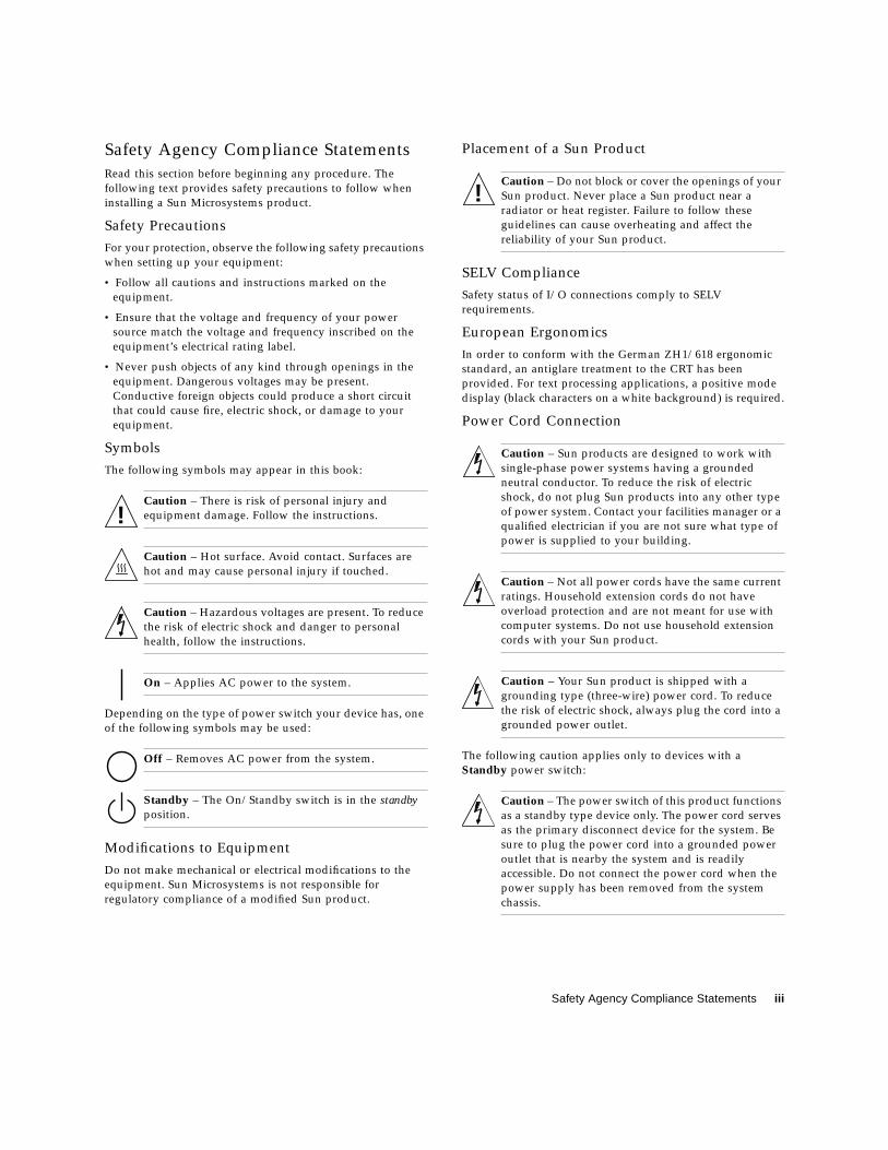
Symbols
The following symbols may appear in this book:
Caution – There is risk of personal injury and
equipment damage. Follow the instructions.
Caution – Hot surface. Avoid contact. Surfaces are
hot and may cause personal injury if touched.
Caution – Hazardous voltages are present. To reduce
the risk of electric shock and danger to personal
health, follow the instructions.
On – Applies AC power to the system.
Depending on the type of power switch your device has, one
of the following symbols may be used:
Off – Removes AC power from the system.
Standby – The On/Standby switch is in the standbyposition.
Modifications to Equipment
Do not make mechanical or electrical modifications to the
equipment. Sun Microsystems is not responsible for
regulatory compliance of a modified Sun product.
Placement of a Sun Product
Caution – Do not block or cover the openings of your
Sun product. Never place a Sun product near a
radiator or heat register. Failure to follow these
guidelines can cause overheating and affect the
reliability of your Sun product.
SELV Compliance
Safety status of I/O connections comply to SELV
requirements.
European Ergonomics
In order to conform with the German ZH1/618 ergonomic
standard, an antiglare treatment to the CRT has been
provided. For text processing applications, a positive mode
display (black characters on a white background) is required.
Power Cord Connection
Caution – Sun products are designed to work with
single-phase power systems having a grounded
neutral conductor. To reduce the risk of electric
shock, do not plug Sun products into any other type
of power system. Contact your facilities manager or a
qualified electrician if you are not sure what type of
power is supplied to your building.
Caution – Not all power cords have the same current
ratings. Household extension cords do not have
overload protection and are not meant for use with
computer systems. Do not use household extension
cords with your Sun product.
Caution – Your Sun product is shipped with a
grounding type (three-wire) power cord. To reduce
the risk of electric shock, always plug the cord into a
grounded power outlet.
The following caution applies only to devices with a
Standby power switch:
Caution – The power switch of this product functions
as a standby type device only. The power cord serves
as the primary disconnect device for the system. Be
sure to plug the power cord into a grounded power
outlet that is nearby the system and is readily
accessible. Do not connect the power cord when the
power supply has been removed from the system
chassis.
!
!
iv Sun Enterprise Tape Library 7/3500 Field Service Manual • July 1997
Lithium Battery
Caution – On Sun CPU boards, there is a lithium
battery molded into the real-time clock, SGS No.
MK48T59Y, MK48TXXB-XX, MK48T18-XXXPCZ,
M48T59W-XXXPCZ, or MK48T08. Batteries are not
customer replaceable parts. They may explode if
mishandled. Do not dispose of the battery in fire. Do
not disassemble it or attempt to recharge it.
System Unit Cover
You must remove the cover of your Sun computer system
unit in order to add cards, memory, or internal storage
devices. Be sure to replace the top cover before powering up
your computer system.
Caution – Do not operate Sun products without the
top cover in place. Failure to take this precaution
may result in personal injury and system damage.
Laser Compliance Notice
Sun products that use laser technology comply with
Class 1 laser requirements.
CD-ROM
Caution – Use of controls, adjustments, or the
performance of procedures other than those specified
herein may result in hazardous radiation exposure.
Einhaltung sicherheitsbehördlicherVorschriften
Auf dieser Seite werden Sicherheitsrichtlinien beschrieben,
die bei der Installation von Sun-Produkten zu beachten sind.
Sicherheitsvorkehrungen
Treffen Sie zu Ihrem eigenen Schutz die folgenden
Sicherheitsvorkehrungen, wenn Sie Ihr Gerät installieren:
• Beachten Sie alle auf den Geräten angebrachten
Warnhinweise und Anweisungen.
• Vergewissern Sie sich, daß Spannung und Frequenz Ihrer
Stromquelle mit der Spannung und Frequenz
übereinstimmen, die auf dem Etikett mit den elektrischen
Nennwerten des Geräts angegeben sind.
• Stecken Sie auf keinen Fall irgendwelche Gegenstände in
Öffnungen in den Geräten. Leitfähige Gegenstände
könnten aufgrund der möglicherweise vorliegenden
gefährlichen Spannungen einen Kurzschluß verursachen,
der einen Brand, Stromschlag oder Geräteschaden
herbeiführen kann.
Symbole
Die Symbole in diesem Handbuch haben folgende
Bedeutung:
Achtung – Gefahr von Verletzung und
Geräteschaden. Befolgen Sie die Anweisungen.
Achtung – Hohe Temperatur. Nicht berühren, da
Verletzungsgefahr durch heiße Oberfläche besteht.
Achtung – Gefährliche Spannungen. Anweisungen
befolgen, um Stromschläge und Verletzungen zu
vermeiden.
Ein – Setzt das System unter Wechselstrom.
Je nach Netzschaltertyp an Ihrem Gerät kann eines der
folgenden Symbole benutzt werden:
Aus – Unterbricht die Wechselstromzufuhr zum
Gerät.
Wartezustand (Stand-by-Position) - Der Ein-/
Wartezustand-Schalter steht auf Wartezustand.
Änderungen an Sun-Geräten.
Nehmen Sie keine mechanischen oder elektrischen
Änderungen an den Geräten vor. Sun Microsystems,
übernimmt bei einem Sun-Produkt, das geändert wurde,
keine Verantwortung für die Einhaltung behördlicher
Vorschriften
Aufstellung von Sun-Geräten
Achtung – Um den zuverlässigen Betrieb Ihres Sun-
Geräts zu gewährleisten und es vor Überhitzung zu
schützen, dürfen die Öffnungen im Gerät nicht
blockiert oder verdeckt werden. Sun-Produkte sollten
niemals in der Nähe von Heizkörpern oder
Heizluftklappen aufgestellt werden.
Einhaltung der SELV-Richtlinien
Die Sicherung der I/O-Verbindungen entspricht den
Anforderungen der SELV-Spezifikation.
!
!
Class 1 Laser ProductLuokan 1 Laserlaite
Klasse 1 Laser ApparatLaser Klasse 1
!
!
!
Safety Agency Compliance Statements v
Ergonomie-Richtlinien
Um den Anforderungen der in Deutschland geltenden
Ergonomie-Richtlinie ZH1/618 zu entsprechen, wurde der
Bildschirm entspiegelt. Für Textverarbeitungsanwendungen
wird ein positiver Anzeigemodus (schwarze Zeichen auf
weißem Hintergrund) empfohlen.
Anschluß des Netzkabels
Achtung – Sun-Produkte sind für den Betrieb an
Einphasen-Stromnetzen mit geerdetem Nulleiter
vorgesehen. Um die Stromschlaggefahr zu
reduzieren, schließen Sie Sun-Produkte nicht an
andere Stromquellen an. Ihr Betriebsleiter oder ein
qualifizierter Elektriker kann Ihnen die Daten zur
Stromversorgung in Ihrem Gebäude geben.
Achtung – Nicht alle Netzkabel haben die gleichen
Nennwerte. Herkömmliche, im Haushalt verwendete
Verlängerungskabel besitzen keinen
Überlastungsschutz und sind daher für
Computersysteme nicht geeignet.
Achtung – Ihr Sun-Gerät wird mit einem dreiadrigen
Netzkabel für geerdete Netzsteckdosen geliefert. Um
die Gefahr eines Stromschlags zu reduzieren,
schließen Sie das Kabel nur an eine fachgerecht
verlegte, geerdete Steckdose an.
Die folgende Warnung gilt nur für Geräte mit Wartezustand-
Netzschalter:
Achtung – Der Ein/Aus-Schalter dieses Geräts
schaltet nur auf Wartezustand (Stand-By-Modus).
Um die Stromzufuhr zum Gerät vollständig zu
unterbrechen, müssen Sie das Netzkabel von der
Steckdose abziehen. Schließen Sie den Stecker des
Netzkabels an eine in der Nähe befindliche, frei
zugängliche, geerdete Netzsteckdose an. Schließen
Sie das Netzkabel nicht an, wenn das Netzteil aus der
Systemeinheit entfernt wurde.
Lithiumbatterie
Achtung – CPU-Karten von Sun verfügen über eine
Echtzeituhr mit integrierter Lithiumbatterie (Teile-Nr.
MK48T59Y, MK48TXXB-XX, MK48T18-XXXPCZ,
M48T59W-XXXPCZ, oder MK48T08). Diese Batterie
darf nur von einem qualifizierten Servicetechniker
ausgewechselt werden, da sie bei falscher
Handhabung explodieren kann. Werfen Sie die
Batterie nicht ins Feuer. Versuchen Sie auf keinen
Fall, die Batterie auszubauen oder wiederaufzuladen.
Gehäuseabdeckung
Sie müssen die obere Abdeckung Ihres Sun-Systems
entfernen, um interne Komponenten wie Karten,
Speicherchips oder Massenspeicher hinzuzufügen. Bringen
Sie die obere Gehäuseabdeckung wieder an, bevor Sie Ihr
System einschalten.
Achtung – Bei Betrieb des Systems ohne obere
Abdeckung besteht die Gefahr von Stromschlag und
Systemschäden.
Einhaltung der Richtlinien für LaserSun-Produkte, die mit Laser-Technologie arbeiten,
entsprechen den Anforderungen der Laser Klasse 1.
CD-ROM
Warnung – Die Verwendung von anderen
Steuerungen und Einstellungen oder die
Durchfhrung von Prozeduren, die von den hier
beschriebenen abweichen, knnen gefhrliche
Strahlungen zur Folge haben.
Conformité aux normes de sécurité
Ce texte traite des mesures de sécurité qu’il convient de
prendre pour l’installation d’un produit Sun Microsystems.
Mesures de sécurité
Pour votre protection, veuillez prendre les précautions
suivantes pendant l’installation du matériel :
• Suivre tous les avertissements et toutes les instructions
inscrites sur le matériel.
• Vérifier que la tension et la fréquence de la source
d’alimentation électrique correspondent à la tension et à la
fréquence indiquées sur l’étiquette de classification de
l’appareil.
• Ne jamais introduire d’objets quels qu’ils soient dans une
des ouvertures de l’appareil. Vous pourriez vous trouver
en présence de hautes tensions dangereuses. Tout objet
conducteur introduit de la sorte pourrait produire un
court-circuit qui entraînerait des flammes, des risques
d’électrocution ou des dégâts matériels.
!
!
Class 1 Laser ProductLuokan 1 Laserlaite
Klasse 1 Laser ApparatLaser Klasse 1
!
vi Sun Enterprise Tape Library 7/3500 Field Service Manual • July 1997
Symboles
Vous trouverez ci-dessous la signification des différents
symboles utilisés :
Attention : risques de blessures corporelles et de
dégâts matériels. Veuillez suivre les instructions.
Attention : surface à température élevée. Evitez le
contact. La température des surfaces est élevée et leur
contact peut provoquer des blessures corporelles.
Attention : présence de tensions dangereuses. Pour
éviter les risques d’électrocution et de danger pour la
santé physique, veuillez suivre les instructions.
MARCHE – Votre système est sous tension (courant
alternatif).
Un des symboles suivants sera peut-être utilisé en fonction
du type d'interrupteur de votre système:
ARRET – Votre système est hors tension (courant
alternatif).
VEILLEUSE – L'interrupteur Marche/Veilleuse est
en position « Veilleuse ».
Modification du matériel
Ne pas apporter de modification mécanique ou électrique au
matériel. Sun Microsystems n’est pas responsable de la
conformité réglementaire d’un produit Sun qui a été modifié.
Positionnement d’un produit Sun
Attention : pour assurer le bon fonctionnement de
votre produit Sun et pour l’empêcher de surchauffer,
il convient de ne pas obstruer ni recouvrir les
ouvertures prévues dans l’appareil. Un produit Sun
ne doit jamais être placé à proximité d’un radiateur
ou d’une source de chaleur.
Conformité SELV
Sécurité : les raccordements E/S sont conformes aux normes
SELV.
Ergonomie européenne
Conformément à la norme d’ergonomie allemande ZH1/618,
le CRT a été soumis à un traitement antireflets. Pour le
traitement de texte, un affichage en mode positif (c’est-à-dire
des caractères noirs sur fond blanc) est nécessaire.
Connexion du cordon d’alimentation
Attention : les produits Sun sont conçus pour
fonctionner avec des alimentations monophasées
munies d’un conducteur neutre mis à la terre. Pour
écarter les risques d’électrocution, ne pas brancher de
produit Sun dans un autre type d’alimentation
secteur. En cas de doute quant au type d’alimentation
électrique du local, veuillez vous adresser au
directeur de l’exploitation ou à un électricien qualifié.
Attention : tous les cordons d’alimentation n’ont pas
forcément la même puissance nominale en matière de
courant. Les rallonges d’usage domestique n’offrent
pas de protection contre les surcharges et ne sont pas
prévues pour les systèmes d’ordinateurs. Ne pas
utiliser de rallonge d’usage domestique avec votre
produit Sun.
Attention : votre produit Sun a été livré équipé d’un
cordon d’alimentation à trois fils (avec prise de terre).
Pour écarter tout risque d’électrocution, branchez
toujours ce cordon dans une prise mise à la terre.
L'avertissement suivant s'applique uniquement aux systèmes
équipés d'un interrupteur VEILLEUSE:
Attention : le commutateur d’alimentation de ce
produit fonctionne comme un dispositif de mise en
veille uniquement. C’est la prise d’alimentation qui
sert à mettre le produit hors tension. Veillez donc à
installer le produit à proximité d’une prise murale
facilement accessible. Ne connectez pas la prise
d’alimentation lorsque le châssis du système n’est
plus alimenté.
Batterie au lithium
Attention : sur les cartes CPU Sun, une batterie au
lithium (référence MK48T59Y, MK48TXXB-XX,
MK48T18-XXXPCZ, M48T59W-XXXPCZ, ou
MK48T08.) a été moulée dans l’horloge temps réel
SGS. Les batteries ne sont pas des pièces
remplaçables par le client. Elles risquent d’exploser
en cas de mauvais traitement. Ne pas jeter la batterie
au feu. Ne pas la démonter ni tenter de la recharger.
Couvercle
Pour ajouter des cartes, de la mémoire, ou des unités de
stockage internes, vous devrez démonter le couvercle de
l’unité système Sun. Ne pas oublier de remettre ce couvercle
en place avant de mettre le système sous tension.
!
!!
Safety Agency Compliance Statements vii
Attention : il est dangereux de faire fonctionner un
produit Sun sans le couvercle en place. Si l’on néglige
cette précaution, on encourt des risques de blessures
corporelles et de dégâts matériels.
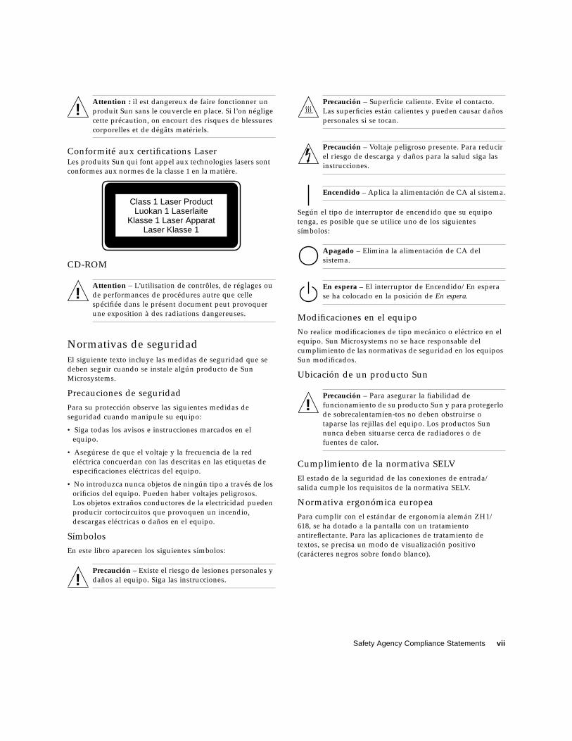
Conformité aux certifications LaserLes produits Sun qui font appel aux technologies lasers sont
conformes aux normes de la classe 1 en la matière.
CD-ROM
Attention – L’utilisation de contrôles, de réglages ou
de performances de procédures autre que celle
spécifiée dans le présent document peut provoquer
une exposition à des radiations dangereuses.
Normativas de seguridad
El siguiente texto incluye las medidas de seguridad que se
deben seguir cuando se instale algún producto de Sun
Microsystems.
Precauciones de seguridad
Para su protección observe las siguientes medidas de
seguridad cuando manipule su equipo:
• Siga todas los avisos e instrucciones marcados en el
equipo.
• Asegúrese de que el voltaje y la frecuencia de la red
eléctrica concuerdan con las descritas en las etiquetas de
especificaciones eléctricas del equipo.
• No introduzca nunca objetos de ningún tipo a través de los
orificios del equipo. Pueden haber voltajes peligrosos.
Los objetos extraños conductores de la electricidad pueden
producir cortocircuitos que provoquen un incendio,
descargas eléctricas o daños en el equipo.
Símbolos
En este libro aparecen los siguientes símbolos:
Precaución – Existe el riesgo de lesiones personales y
daños al equipo. Siga las instrucciones.
Precaución – Superficie caliente. Evite el contacto.
Las superficies están calientes y pueden causar daños
personales si se tocan.
Precaución – Voltaje peligroso presente. Para reducir
el riesgo de descarga y daños para la salud siga las
instrucciones.
Encendido – Aplica la alimentación de CA al sistema.
Según el tipo de interruptor de encendido que su equipo
tenga, es posible que se utilice uno de los siguientes
símbolos:
Apagado – Elimina la alimentación de CA del
sistema.
En espera – El interruptor de Encendido/En espera
se ha colocado en la posición de En espera.
Modificaciones en el equipo
No realice modificaciones de tipo mecánico o eléctrico en el
equipo. Sun Microsystems no se hace responsable del
cumplimiento de las normativas de seguridad en los equipos
Sun modificados.
Ubicación de un producto Sun
Precaución – Para asegurar la fiabilidad de
funcionamiento de su producto Sun y para protegerlo
de sobrecalentamien-tos no deben obstruirse o
taparse las rejillas del equipo. Los productos Sun
nunca deben situarse cerca de radiadores o de
fuentes de calor.
Cumplimiento de la normativa SELV
El estado de la seguridad de las conexiones de entrada/
salida cumple los requisitos de la normativa SELV.
Normativa ergonómica europea
Para cumplir con el estándar de ergonomía alemán ZH1/
618, se ha dotado a la pantalla con un tratamiento
antireflectante. Para las aplicaciones de tratamiento de
textos, se precisa un modo de visualización positivo
(carácteres negros sobre fondo blanco).
!
Class 1 Laser ProductLuokan 1 Laserlaite
Klasse 1 Laser ApparatLaser Klasse 1
!
!
!
viii Sun Enterprise Tape Library 7/3500 Field Service Manual • July 1997
Conexión del cable de alimentación eléctrica
Precaución – Los productos Sun están diseñados
para
trabajar en una red eléctrica monofásica con toma de
tierra. Para reducir el riesgo de descarga eléctrica, no
conecte los productos Sun a otro tipo de sistema de
alimentación eléctrica. Póngase en contacto con el
responsable de mantenimiento o con un electricista
cualificado si no está seguro del sistema de
alimentación eléctrica del que se dispone en su
edificio.
Precaución – No todos los cables de alimentación
eléctrica tienen la misma capacidad. Los cables de
tipo doméstico no están provistos de protecciones
contra sobrecargas y por tanto no son apropiados
para su uso con computadores. No utilice
alargadores de tipo doméstico para conectar sus
productos Sun.
Precaución – Con el producto Sun se proporciona un
cable de alimentación con toma de tierra. Para
reducir el riesgo de descargas eléctricas conéctelo
siempre a un enchufe con toma de tierra.
La siguiente advertencia se aplica solamente a equipos con
un interruptor de encendido que tenga una posición "En
espera":
Precaución – El interruptor de encendido de este
producto funciona exclusivamente como un
dispositivo de puesta en espera. El enchufe de la
fuente de alimentación está diseñado para ser el
elemento primario de desconexión del equipo. El
equipo debe instalarse cerca del enchufe de forma
que este último pueda ser fácil y rápidamente
accesible. No conecte el cable de alimentación cuando
se ha retirado la fuente de alimentación del chasis del
sistema.
Batería de litio
Precaución – En las placas de CPU Sun hay una
batería de litio insertada en el reloj de tiempo real,
tipo SGS Núm. MK48T59Y, MK48TXXB-XX,
MK48T18-XXXPCZ, M48T59W-XXXPCZ, o MK48T08.
Las baterías no son elementos reemplazables por el
propio cliente. Pueden explotar si se manipulan de
forma errónea. No arroje las baterías al fuego. No las
abra o intente recargarlas.
Tapa de la unidad del sistema
Debe quitar la tapa del sistema cuando sea necesario añadir
tarjetas, memoria o dispositivos de almacenamiento internos.
Asegúrese de cerrar la tapa superior antes de volver a
encender el equipo.
Precaución – Es peligroso hacer funcionar los
productos Sun sin la tapa superior colocada. El hecho
de no tener en cuenta esta precaución puede
ocasionar daños personales o perjudicar el
funcionamiento del equipo.
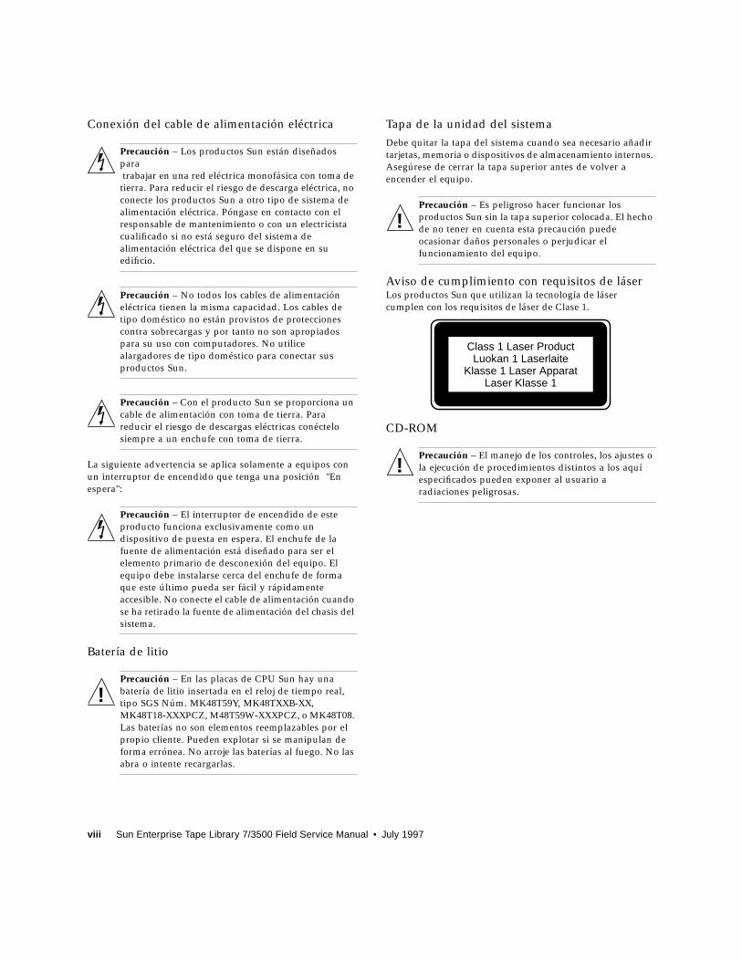
Aviso de cumplimiento con requisitos de láserLos productos Sun que utilizan la tecnología de láser
cumplen con los requisitos de láser de Clase 1.
CD-ROM
Precaución – El manejo de los controles, los ajustes o
la ejecución de procedimientos distintos a los aquí
especificados pueden exponer al usuario a
radiaciones peligrosas.
!
!
Class 1 Laser ProductLuokan 1 Laserlaite
Klasse 1 Laser ApparatLaser Klasse 1
!
Safety Agency Compliance Statements ix
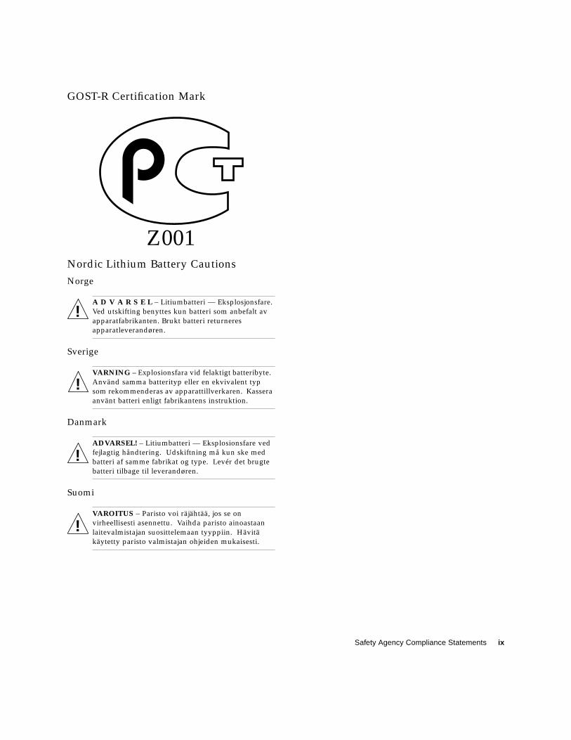
GOST-R Certification Mark
Z001Nordic Lithium Battery Cautions
Norge
A D V A R S E L – Litiumbatteri — Eksplosjonsfare.
Ved utskifting benyttes kun batteri som anbefalt av
apparatfabrikanten. Brukt batteri returneres
apparatleverandøren.
Sverige
VARNING – Explosionsfara vid felaktigt batteribyte.
Använd samma batterityp eller en ekvivalent typ
som rekommenderas av apparattillverkaren. Kassera
använt batteri enligt fabrikantens instruktion.
Danmark
ADVARSEL! – Litiumbatteri — Eksplosionsfare ved
fejlagtig håndtering. Udskiftning må kun ske med
batteri af samme fabrikat og type. Levér det brugte
batteri tilbage til leverandøren.
Suomi
VAROITUS – Paristo voi räjähtää, jos se on
virheellisesti asennettu. Vaihda paristo ainoastaan
laitevalmistajan suosittelemaan tyyppiin. Hävitä
käytetty paristo valmistajan ohjeiden mukaisesti.
!
!
!
!

x Sun Enterprise Tape Library 7/3500 Field Service Manual • July 1997
Contents xi
Contents
Preface xxix
Who Should Use This Book xxix
How This Book Is Organized xxx
1. Library Overview 1
Library Description 2
Supported Tape Drives and Cartridges 2
ETL 7/3500 Library Numbering Conventions 2
Library Components 5
Controller Electronics Assembly 6
Robotics Controller PWA (A1) 7
Actuator Driver PWA (A2) 8
Power Supplies 9
Extension Axis Assembly 10
Extension Drive Motor and Belt 11
Extension Carriage Interconnect PWA 11
Extension Motor (M3) and Encoder 11
Gripper Interconnect PWA 12
Gripper Motor 12
Cartridge-In-Gripper Receiver PWA 12

xii Sun Enterprise Tape Library 7/3500 Field Service Manual • July 1997
Cartridge-In-Gripper Transmitter PWA 12
Bar Code Scanner PWA 13
Y-Axis Confirmation Sensor (S2) 13
X-Carriage Assembly 13
X-Carriage 14
X-Axis Interconnect PWA 14
X-Axis Confirmation Sensor 14
Y-Axis Motor 14
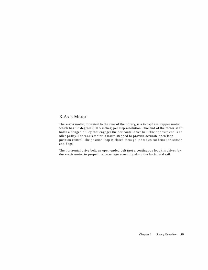
X-Axis Motor 15
Control Panel Assembly 17
Load Port Assembly 17
Load Port Switch 1 19
Load Port Switch 2 19
Front Door Interlock Switch 19
Drive Access Door Interlock Switch 19
Storage Array Door Interlock Switch 19
Load Port Lockout Solenoid 20
Tape Drive Assembly 20
Tape Drives 20
Handle Drive Assembly 20
Tape Drive Interface PWA 20
Fans 21
2. Preventive Maintenance 23
Preventive Maintenance Schedule 23
Required Tools and Supplies 24
▼ To Prepare for Preventive Maintenance 24
Cleaning Procedures 24
▼ To Clean the Fan Filter 25
Contents xiii
▼ To Clean the Rails 26
▼ To Clean the Extension Axis 29
▼ To Clean the Tape Drives 30
▼ To Clean the Rollers 31
Adjustments 32
X-Axis Rollers 33
▼ To Check the X-Axis Assembly Rollers 33
▼ To Adjust the X-Axis Assembly Rollers 33
Y-Axis Rollers 34
▼ To Check the Y-Axis Assembly Rollers 34
▼ To Adjust the Y-Axis Assembly Rollers 34
Y-Axis Belt 35
▼ To Check the Y-Axis Belt Tension 35
▼ To Adjust the Y-Axis Belt Tension 35
X-Axis Belt 37
▼ To Check the X-Axis Belt Tension 37
▼ To Adjust the X-Axis Belt Tension 38
Extension Axis Belt 41
▼ To Check the Extension Axis Belt Tension 41
▼ To Adjust the Extension Axis Belt Tension 43
Lubrication 44
▼ To Lubricate the X-Axis and Y-Axis Rails 44
▼ To Lubricate the Extension Axis Rail and Gripper Cross-Shaft 44
Returning the Library to Operation 45
▼ To Return the Library to Operation 45
3. Troubleshooting and Fault Isolation 47
Maintenance Analysis Procedures (MAPs) 47
xiv Sun Enterprise Tape Library 7/3500 Field Service Manual • July 1997
▼ To Use These Procedures for Troubleshooting 47
Fault Isolation Entry MAP 48
Error Message Entry MAP 49
Mechanical Inspection Entry MAP 50
Online Initialization Entry MAP 51
Online Test Entry MAP 52
Diagnostic Test Entry MAP 53
Host Interface Failure MAP 54
Library Operation Failure MAP 55
Control Panel and Load Port Debug MAP 56
Control Panel and Load Port Debug MAP (Cont.) 57
Motor Power Interlock Clearing MAP 58
Run Diagnostics MAP 59
Diagnostics Initialization MAP 60
Power Entry MAP 61
Self-Test All MAP 62
Self-Test All MAP (Cont.) 63
Home All MAP 64
Inventory MAP 65
Calibration MAP 66
Robotics Controller Fuse Isolation Entry MAP 67
Actuator Driver Fuse Isolation Entry Map 68
Power Supply Evaluation Entry MAP 69
Power Supply Evaluation Entry MAP (Cont.) 70
Gripper Self-Test Failure MAP 71
Extension Self-Test Failure MAP 72
Vertical Self-Test Failure MAP 73

Contents xv
Vertical Self-Test Failure MAP (Cont.) 74
Horizontal Self-Test Failure MAP 75
Horizontal Self-Test Failure MAP (Cont.) 76
Tape Drive Stepper Motor Self-Test Failure MAP 77
Tape Drive Communication Timeout Map 78
Tape Drive Handle Not OK Map 79
NVRAM Checksum Failure Map 80
Vertical Confirmation Sensor Failure Map 81
Horizontal Confirmation Sensor Failure Map 82
Tape Drive Interface PWA Isolation Map 83
4. FRU Removal and Replacement 89
Preparing for Maintenance 89
▼ To Turn Off the Library 89
▼ To Take the Library Offline 90
Removing the Cosmetic Panels 90
▼ To Remove the Top Panel 90
▼ To Remove the Left Panel 90
▼ To Remove the Right Panel 93
▼ To Remove the Front Panel 93
Removing the Controller Electronics Assembly 95
Required Tools 96
▼ To Remove the Controller Electronics Assembly 96
▼ To Replace the Controller Electronics Assembly 96
▼ Adjustments Required After Replacement 97
▼ To Troubleshoot 97
FRU Removal and Replacement Procedures 98
X-Axis Interconnect PWA 99

xvi Sun Enterprise Tape Library 7/3500 Field Service Manual • July 1997
Required Tools 99
▼ To Remove the X-Axis Interconnect PWA 99
▼ To Replace the X-Axis Interconnect PWA 100
▼ To Troubleshoot 100
X-Axis Stepper Motor Assembly 102
Required Tools 102
▼ To Remove the X-Axis Stepper Motor Assembly 102
▼ To Replace the X-Axis Stepper Motor Assembly 102
▼ To Make Adjustments Required After Replacement 103
Y-Axis Stepper Motor Assembly 104
Required Tools 104
▼ To Remove the Y-Axis Stepper Motor Assembly 104
▼ To Replace the Y-Axis Stepper Motor Assembly 105
▼ To Make Adjustments Required After Replacement 105
Load Port Door Lockout Solenoid 107
Required Tools 107
▼ To Remove the Load Port Door Lockout Solenoid 107
▼ To Replace the Load Port Door Lockout Solenoid 108
▼ To Make Adjustments Required After Replacement 108
Front Door Interlock Switch 110
Required Tools 110
▼ To Remove the Front Door Interlock Switch 110
▼ Replacing the Front Door Interlock Switch 110
Y-Axis Umbilical Cable 112
Required Tools 112
▼ To Remove the Y-Axis Umbilical Cable 112
▼ To Replace the Y-Axis Umbilical Cable 113
Contents xvii
X-Axis Umbilical Cable 114
Required Tools 114
▼ To Remove the X-Axis Umbilical Cable 114
▼ To Replace the X-Axis Umbilical Cable 114
X-Axis Drive Belt 116
Required Tools 116
▼ To Remove the X-Axis Drive Belt 116
▼ To Replace the X-Axis Drive Belt 116
▼ To Make Adjustments Required After Replacement 116
Y-Axis Drive Belt 118
Required Tools 118
▼ To Remove the Y-Axis Drive Belt 118
▼ To Replace the Y-Axis Drive Belt 118
▼ To Make Adjustments Required After Replacement 119
DC Fan Assembly 121
Required Tools 121
▼ To Remove the Front Fan 121
▼ To Replace the Front Fan 121
▼ To Make Adjustments Required After Replacing the Front Fan 122
▼ To Remove the Controller Electronics Assembly Fan 123
▼ To Replace the Controller Electronics Assembly Fan 123
▼ To Remove the Rear Fan 124
▼ Replacing the Rear Fan 124
Extension Axis Assembly 126
Required Tools 126
▼ To Remove the Extension Axis Assembly 126
▼ To Replace the Extension Axis Assembly 126
xviii Sun Enterprise Tape Library 7/3500 Field Service Manual • July 1997
▼ To Make Adjustments Required After Replacement 126
Tape Drive 127
Required Tools 127
▼ To Remove a Tape Drive 127
▼ To Replace a Tape Drive 128
▼ To Make Adjustments Required After Replacement 128
Tape Drive Interface PWA 130
Required Tools 130
▼ To Remove a Tape Drive Interface PWA 130
▼ To Replace a Tape Drive Interface PWA 130
▼ To Troubleshoot 130
Tape Drive Stepper Motor Assembly 132
Required Tools 132
▼ To Remove a Tape Drive Stepper Motor Assembly 132
▼ To Remove a Tape Drive Stepper Motor Assembly 132
▼ To Replace a Tape Drive Stepper Motor Assembly 132
▼ To Make Adjustments Required After Replacement 132
Tape Drive Tray Assembly 134
Required Tools 134
▼ To Remove a Tape Drive Tray Assembly 134
▼ To Replace a Tape Drive Tray Assembly 134
Tape Drive Distribution PWA 136
Required Tools 136
▼ To Remove a Tape Drive Distribution PWA 136
▼ To Replace a Tape Drive Distribution PWA 136
▼ To Troubleshoot 136
Tape Drive MUX PWA 138

Contents xix
Required Tools 138
▼ To Remove the Tape Drive MUX PWA 138
▼ To Replace the Tape Drive MUX PWA 139
Control Panel Assembly 141
Required Tools 141
▼ To Remove the Control Panel Assembly 141
▼ To Replace the Control Panel Assembly 141
▼ To Make Adjustments Required After Replacement 142
X-Axis Confirmation Sensor 143
Required Tools 143
▼ To Remove the X-Axis Confirmation Sensor 143
▼ To Replace the X-Axis Confirmation Sensor 143
▼ To Make Adjustments Required After Replacement 143
Robotics Controller PWA 145
Required Tools 145
▼ To Remove the Robotics Controller PWA 145
▼ To Replace the Robotics Controller PWA 146
▼ To Make Adjustments Required After Replacement 146
Actuator Driver PWA 148
Required Tools 148
▼ To Remove the Actuator Driver PWA 148
▼ To Replace the Actuator Driver PWA 149
PC Logic Power Supply Assembly 151
Required Tools 151
▼ To Remove the Top PC Logic Power Supply 151
▼ To Replace the Top PC Logic Power Supply 152
▼ To Remove the Bottom PC Logic Power Supply 152

xx Sun Enterprise Tape Library 7/3500 Field Service Manual • July 1997
▼ To Replace the Bottom PC Logic Power Supply 152
▼ To Make Adjustments Required After Replacement 152
▼ To Troubleshoot 152
Motor Power Supply Assembly 154
Required Tools 154
▼ To Remove the Motor Power Supply Assembly 154
▼ To Replace the Motor Power Supply Assembly 155
▼ To Troubleshoot 155
Light Bulb 157
Required Tools 157
▼ To Remove the Light Bulb 157
▼ To Replace the Light Bulb 157
Reassembling the Library 159
Replacing the Cosmetic Panels 159
▼ To Replace the Front Panel 159
▼ To Replace the Left Panel 159
▼ To Replace the Right Panel 160
▼ To Replace the Top Panel 160
▼ To Apply Power to the Library 160
▼ To Place the Library Online 161
A. Control Panel Menus 163
Control Panel Overview 163
Control Panel Navigation 165
Using Library Controls 165
Opening a Screen 165
Exiting a Screen 165
Basic Library Information 166

Contents xxi
Overview Screen 166
Tapes Screen 167
Viewing Screen Elements 167
Operator Screen 169
Configure Library 169
▼ To Configure Library Attributes: 169
SCSI ID Assignment Guidelines 170
Configure Options 171
▼ To Configure Library Options 172
Move Cartridges 173
▼ To Move a Cartridge 173
Inventory Tapes 174
▼ To Perform an Inventory 174
Calibrate Library 175
▼ To Calibrate Library Elements 175
Exercise Library 175
▼ To Exercise Library Elements 176
Unload Drives 176
▼ To Unload a Drive 176
Unload the Load Port 177
▼ To Unload the Load Port 177
Service Screen 178
Statistics 178
Actuator 179
Systest Library Results 179
Systest Library 180
▼ To Test Library Operation 180

xxii Sun Enterprise Tape Library 7/3500 Field Service Manual • July 1997
Operate Axes 181
▼ To Operate an Axis 181
Initialize Nonvol Statistics 182
Initialize Nonvol Config 182
Change Password 182
B. Sense Data Values 183
Glossary 1
Index 1
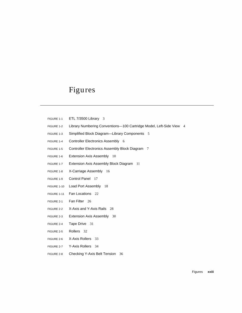
Figures xxiii
Figures
FIGURE 1-1 ETL 7/3500 Library 3
FIGURE 1-2 Library Numbering Conventions—100 Cartridge Model, Left-Side View 4
FIGURE 1-3 Simplified Block Diagram—Library Components 5
FIGURE 1-4 Controller Electronics Assembly 6
FIGURE 1-5 Controller Electronics Assembly Block Diagram 7
FIGURE 1-6 Extension Axis Assembly 10
FIGURE 1-7 Extension Axis Assembly Block Diagram 11
FIGURE 1-8 X-Carriage Assembly 16
FIGURE 1-9 Control Panel 17
FIGURE 1-10 Load Port Assembly 18
FIGURE 1-11 Fan Locations 22
FIGURE 2-1 Fan Filter 26
FIGURE 2-2 X-Axis and Y-Axis Rails 28
FIGURE 2-3 Extension Axis Assembly 30
FIGURE 2-4 Tape Drive 31
FIGURE 2-5 Rollers 32
FIGURE 2-6 X-Axis Rollers 33
FIGURE 2-7 Y-Axis Rollers 34
FIGURE 2-8 Checking Y-Axis Belt Tension 36
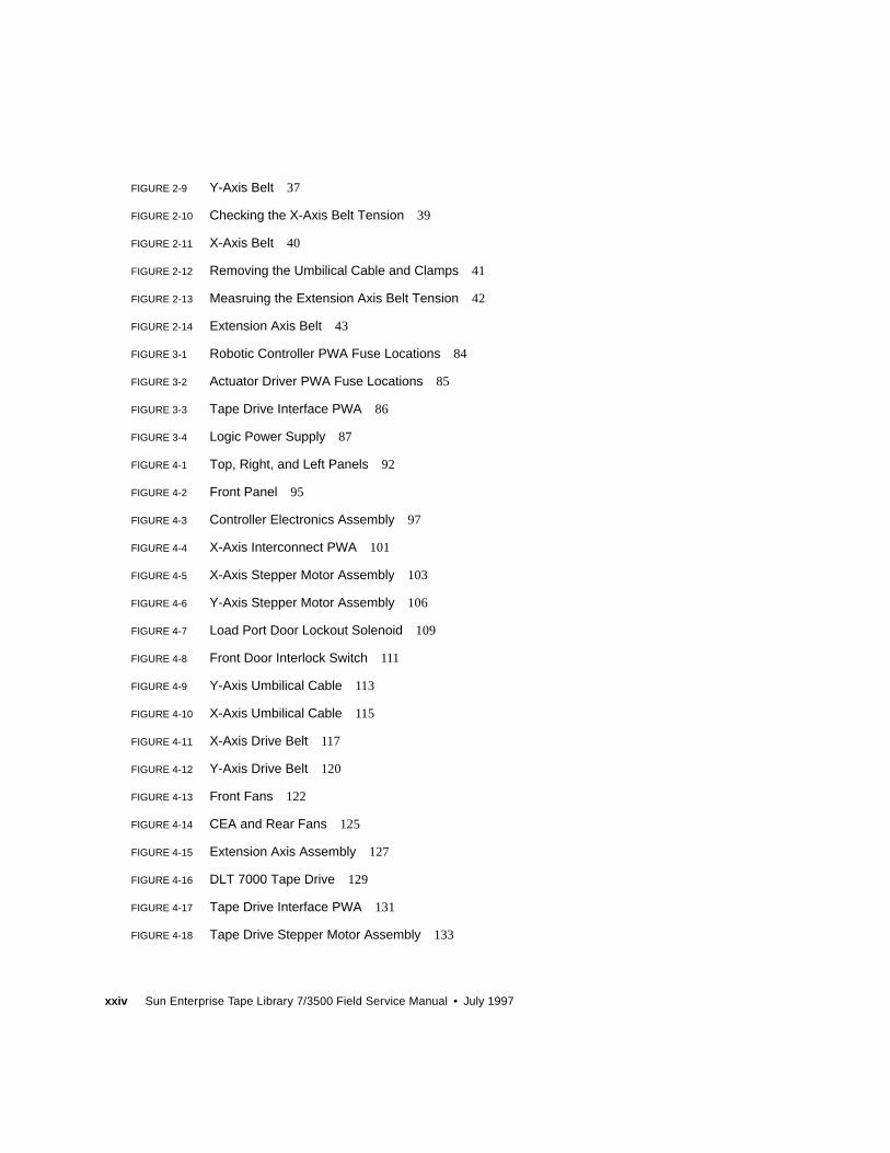
xxiv Sun Enterprise Tape Library 7/3500 Field Service Manual • July 1997
FIGURE 2-9 Y-Axis Belt 37
FIGURE 2-10 Checking the X-Axis Belt Tension 39
FIGURE 2-11 X-Axis Belt 40
FIGURE 2-12 Removing the Umbilical Cable and Clamps 41
FIGURE 2-13 Measruing the Extension Axis Belt Tension 42
FIGURE 2-14 Extension Axis Belt 43
FIGURE 3-1 Robotic Controller PWA Fuse Locations 84
FIGURE 3-2 Actuator Driver PWA Fuse Locations 85
FIGURE 3-3 Tape Drive Interface PWA 86
FIGURE 3-4 Logic Power Supply 87
FIGURE 4-1 Top, Right, and Left Panels 92
FIGURE 4-2 Front Panel 95
FIGURE 4-3 Controller Electronics Assembly 97
FIGURE 4-4 X-Axis Interconnect PWA 101
FIGURE 4-5 X-Axis Stepper Motor Assembly 103
FIGURE 4-6 Y-Axis Stepper Motor Assembly 106
FIGURE 4-7 Load Port Door Lockout Solenoid 109
FIGURE 4-8 Front Door Interlock Switch 111
FIGURE 4-9 Y-Axis Umbilical Cable 113
FIGURE 4-10 X-Axis Umbilical Cable 115
FIGURE 4-11 X-Axis Drive Belt 117
FIGURE 4-12 Y-Axis Drive Belt 120
FIGURE 4-13 Front Fans 122
FIGURE 4-14 CEA and Rear Fans 125
FIGURE 4-15 Extension Axis Assembly 127
FIGURE 4-16 DLT 7000 Tape Drive 129
FIGURE 4-17 Tape Drive Interface PWA 131
FIGURE 4-18 Tape Drive Stepper Motor Assembly 133
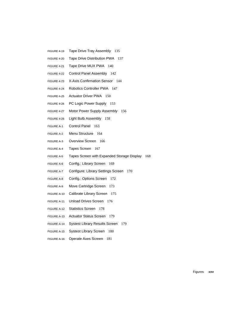
Figures xxv
FIGURE 4-19 Tape Drive Tray Assembly 135
FIGURE 4-20 Tape Drive Distribution PWA 137
FIGURE 4-21 Tape Drive MUX PWA 140
FIGURE 4-22 Control Panel Assembly 142
FIGURE 4-23 X-Axis Confirmation Sensor 144
FIGURE 4-24 Robotics Controller PWA 147
FIGURE 4-25 Actuator Driver PWA 150
FIGURE 4-26 PC Logic Power Supply 153
FIGURE 4-27 Motor Power Supply Assembly 156
FIGURE 4-28 Light Bulb Assembly 158
FIGURE A-1 Control Panel 163
FIGURE A-2 Menu Structure 164
FIGURE A-3 Overview Screen 166
FIGURE A-4 Tapes Screen 167
FIGURE A-5 Tapes Screen with Expanded Storage Display 168
FIGURE A-6 Config.: Library Screen 169
FIGURE A-7 Configure: Library Settings Screen 170
FIGURE A-8 Config.: Options Screen 172
FIGURE A-9 Move Cartridge Screen 173
FIGURE A-10 Calibrate Library Screen 175
FIGURE A-11 Unload Drives Screen 176
FIGURE A-12 Statistics Screen 178
FIGURE A-13 Actuator Status Screen 179
FIGURE A-14 Systest Library Results Screen 179
FIGURE A-15 Systest Library Screen 180
FIGURE A-16 Operate Axes Screen 181

xxvi Sun Enterprise Tape Library 7/3500 Field Service Manual • July 1997
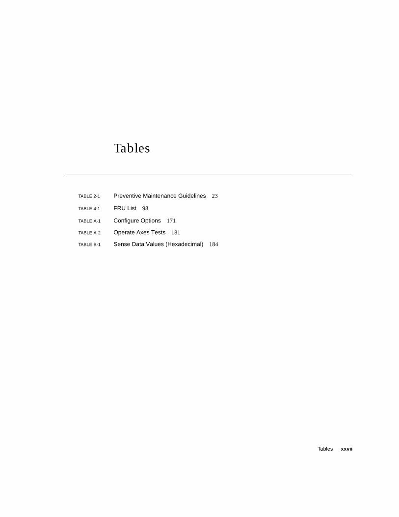
Tables xxvii
Tables
TABLE 2-1 Preventive Maintenance Guidelines 23
TABLE 4-1 FRU List 98
TABLE A-1 Configure Options 171
TABLE A-2 Operate Axes Tests 181
TABLE B-1 Sense Data Values (Hexadecimal) 184

xxviii Sun Enterprise Tape Library 7/3500 Field Service Manual • July 1997

xxix
Preface
This book explains how to operate the Sun Enterprise Tape Library 7/3500. It
assumes that the library has already been unpacked and installed using instructions
found in the Enterprise Tape Library 7/3500 Unpacking Instructions and the EnterpriseTape Library 7/3500 Facilities Planning and Installation Guide.
First read the “Safety Agency Compliance” section at the beginning of this
document. Then refer to the specific chapters to find the information you need.
Who Should Use This Book
This book is designed to aid nontechnical users in the operation of the tape library
system. It begins with a general description of library components and continues
with detailed descriptions of control panel menu functions and specific operating
procedures. It also contains basic troubleshooting information.
This book does not address highly technical issues and procedures, such as
hardware maintenance, diagnostic software operation, or library software
development. To obtain this information, authorized field service engineers and
system programmers should refer to the following documents:
■ Sun Enterprise Tape Library 7/3500 Diagnostic Software User’s Manual
■ Sun Enterprise Tape Library 7/3500 Software Interface Guide
xxx Sun Enterprise Tape Library 7/3500 Field Service Manual • July 1997
How This Book Is Organized
This document is divided into the following sections:
■ Chapter 1, “Library Overview,” provides a general overview of the library and
descriptions of the components comprising the library.
■ Chapter 2, “Preventive Maintenance,” provides guidelines and procedures for
aligning, adjusting, cleaning, and lubricating specific components of the library.
■ Chapter 3, “Troubleshooting and Fault Isolation,” provides the troubleshooting
and fault isolation procedures for the ETL 7/3500 library.
■ Chapter 4, “FRU Removal and Replacement,” contains a list of all field
replaceable units (FRUs) of the ATL 7100 Series Library and the procedures for
removing and replacing them.
■ Appendix A, “Control Panel Menus,” provides an overview of the control panelmenus.
■ Appendix B, “Sense Data Values,” lists message information that can be sent from
the ETL 7/3500 library to the host computer.

1
CHAPTER 1
Library Overview
This chapter provides a general overview of the ETL 7/3500 Library and
descriptions of the components comprising the library.
2 Sun Enterprise Tape Library 7/3500 Field Service Manual • July 1997
Library Description
The ETL 7/3500 Library (FIGURE 1-1) is the automated storage and retrieval
component of an automated tape library system. It contains up to seven DLT™7000
tape drives and can store a maximum of 96 Digital Linear Tape cartridges in a fixed
storage array (FSA). An operator-accessible load port at the front of the library can
hold an additional four tape cartridges for a maximum total of 100.
A host computer communicates with the library through a SCSI interface using the
SCSI-2 medium changer command set. In a typical operation, the host commands
the robotics to transfer tape cartridges between storage bins (in the FSA), tape
drives, or the load port. Each time a tape cartridge is transferred, a gripping
mechanism is moved to the tape cartridge location where it “picks” the tape
cartridge, moves it to the designated (new) location, and then “places” it.
Supported Tape Drives and Cartridges
The ETL 7/3500 Library is capable of supporting up to seven DLT™7000 tape drives.
The library is also capable of supporting the CompacTape III and CompacTape IVcartridges, which are dark gray and black, respectively.
Caution – DO NOT USE CompacTape I, CompacTape II or CompacTape IIIXT tape
cartridges in this library.
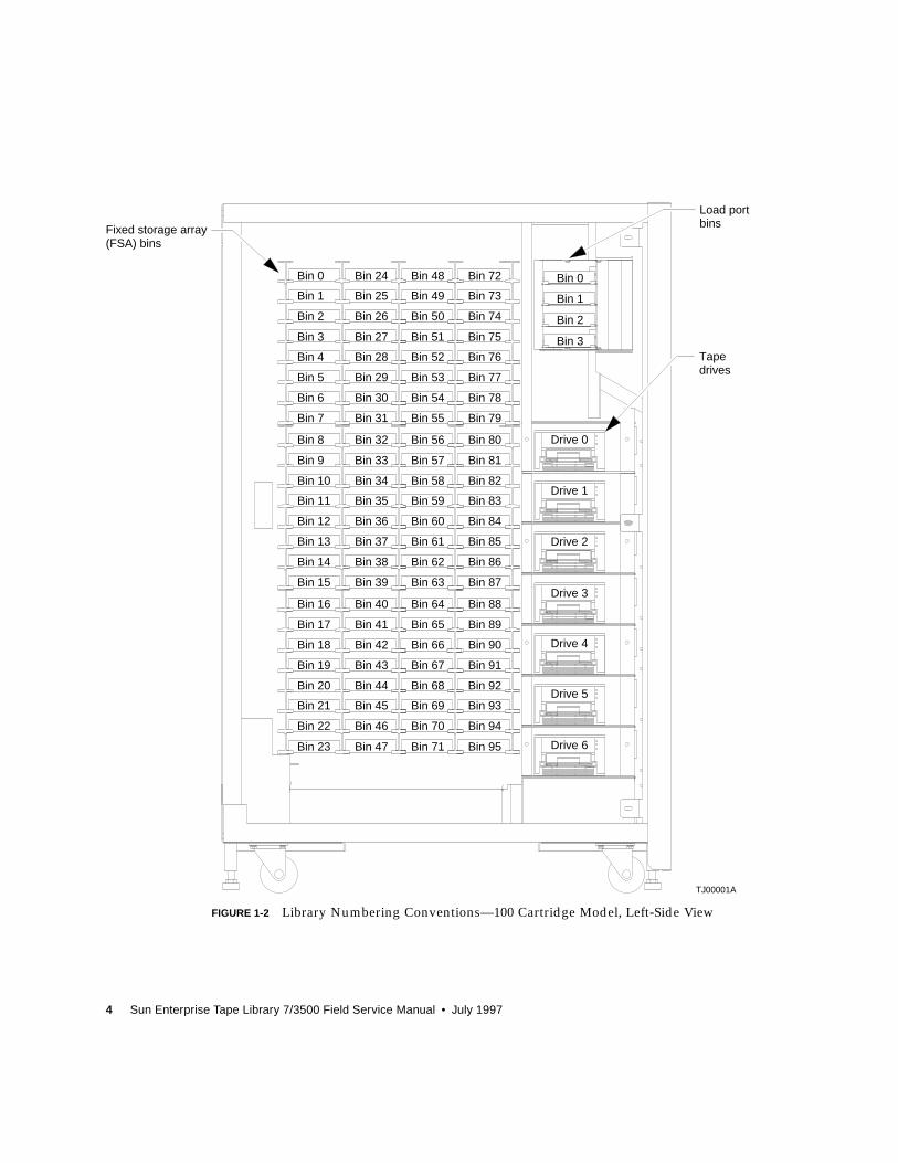
ETL 7/3500 Library Numbering Conventions
FIGURE 1-2 shows the numbering convention for the 100-cartridge library's fixed
storage array bins, load port bins, and tape drives. This numbering convention is
used in the diagnostic software and the library menu mode, which is viewed in the
status display area of the control panel.
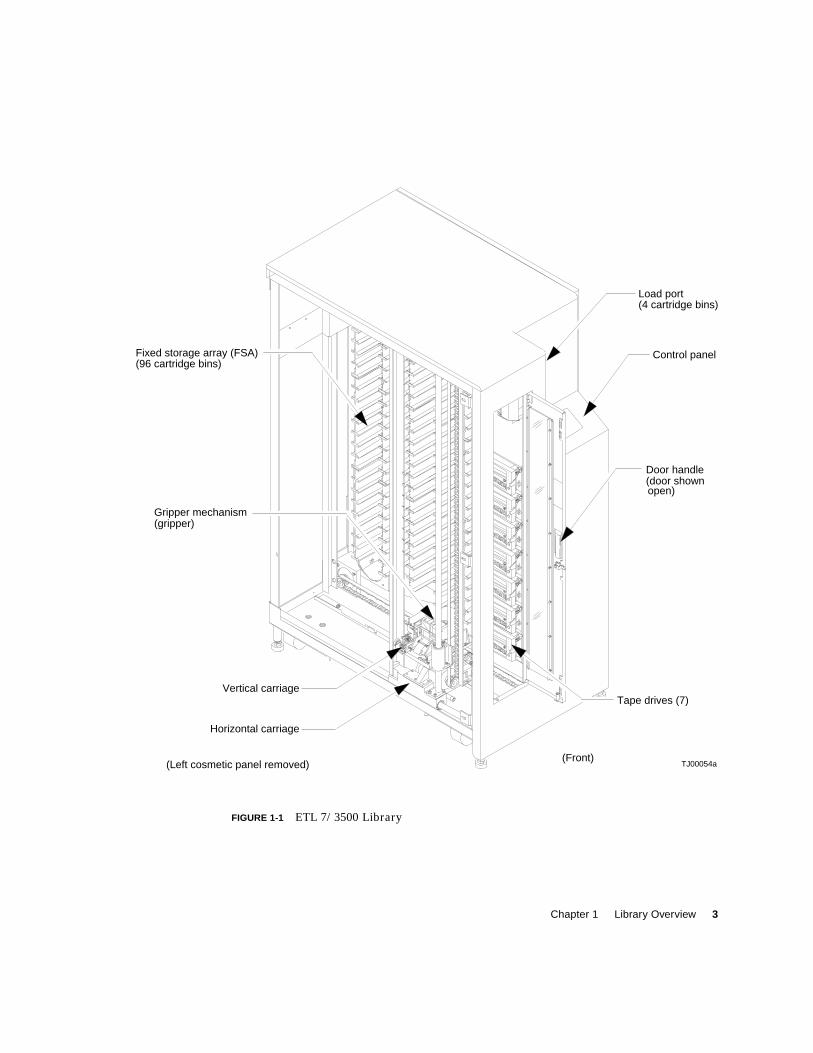
Chapter 1 Library Overview 3
FIGURE 1-1 ETL 7/3500 Library
Control panel
Load port
Door handle
Tape drives (7)
Fixed storage array (FSA)
Horizontal carriage
Vertical carriage
(96 cartridge bins)
(4 cartridge bins)
(door shown
(Front)
Gripper mechanism(gripper)
(Left cosmetic panel removed) TJ00054a
open)
4 Sun Enterprise Tape Library 7/3500 Field Service Manual • July 1997
FIGURE 1-2 Library Numbering Conventions—100 Cartridge Model, Left-Side View
TJ00001A
Load port
Fixed storage array
Tape
Bin 0
Bin 1
Bin 2
Bin 3
Bin 0
Bin 1
Bin 2
Bin 3
Bin 4
Bin 24
Bin 25
Bin 26
Bin 27
Bin 28
Bin 48
Bin 49
Bin 50
Bin 51
Bin 52
Bin 72
Bin 73
Bin 74
Bin 75
Bin 76
Bin 5
Bin 6
Bin 7
Bin 8
Bin 9
Bin 29
Bin 30
Bin 31
Bin 32
Bin 33
Bin 53
Bin 54
Bin 55
Bin 56
Bin 57
Bin 77
Bin 78
Bin 79
Bin 80
Bin 81
Bin 10
Bin 11
Bin 12
Bin 13
Bin 14
Bin 34
Bin 35
Bin 36
Bin 37
Bin 38
Bin 58
Bin 59
Bin 60
Bin 61
Bin 62
Bin 82
Bin 83
Bin 84
Bin 85
Bin 86
Bin 15
Bin 16
Bin 17
Bin 18
Bin 19
Bin 39
Bin 40
Bin 41
Bin 42
Bin 43
Bin 63
Bin 64
Bin 65
Bin 66
Bin 67
Bin 87
Bin 88
Bin 89
Bin 90
Bin 91
Bin 20
Bin 21
Bin 22
Bin 23
Bin 44
Bin 45
Bin 46
Bin 47
Bin 68
Bin 69
Bin 70
Bin 71
Bin 92
Bin 93
Bin 94
Bin 95
Drive 0
Drive 1
Drive 2
Drive 3
Drive 4
Drive 5
Drive 6
(FSA) bins
bins
drives
Chapter 1 Library Overview 5
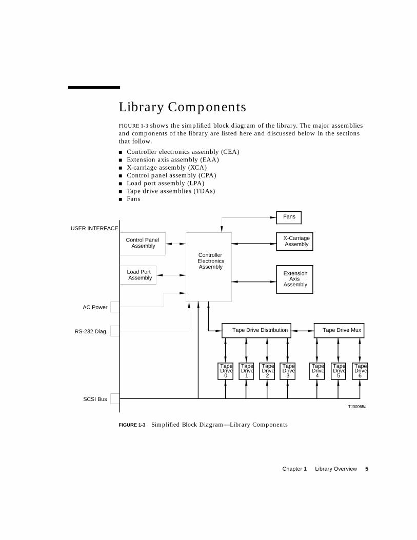
Library Components
FIGURE 1-3 shows the simplified block diagram of the library. The major assemblies
and components of the library are listed here and discussed below in the sections
that follow.
■ Controller electronics assembly (CEA)
■ Extension axis assembly (EAA)
■ X-carriage assembly (XCA)
■ Control panel assembly (CPA)
■ Load port assembly (LPA)
■ Tape drive assemblies (TDAs)
■ Fans
FIGURE 1-3 Simplified Block Diagram—Library Components
TJ00065a
Control PanelAssembly
AssemblyLoad Port
AC Power
RS-232 Diag.
SCSI Bus
USER INTERFACE
ControllerElectronicsAssembly
TapeDrive
0
TapeDrive
1
TapeDrive
2
TapeDrive
3
AssemblyX-Carriage
ExtensionAxis
Fans
Assembly
TapeDrive
4
TapeDrive
5
TapeDrive
6
Tape Drive Distribution Tape Drive Mux
6 Sun Enterprise Tape Library 7/3500 Field Service Manual • July 1997
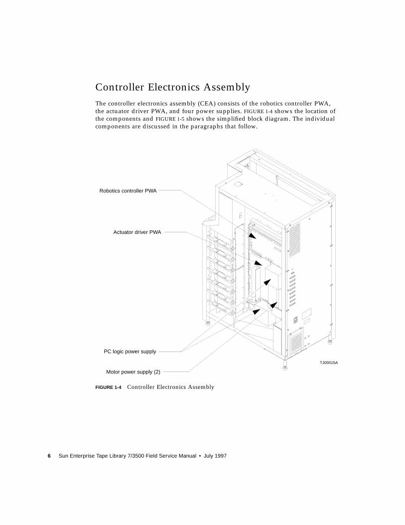
Controller Electronics Assembly
The controller electronics assembly (CEA) consists of the robotics controller PWA,
the actuator driver PWA, and four power supplies. FIGURE 1-4 shows the location of
the components and FIGURE 1-5 shows the simplified block diagram. The individual
components are discussed in the paragraphs that follow.
FIGURE 1-4 Controller Electronics Assembly
Robotics controller PWA
Actuator driver PWA
PC logic power supply
Motor power supply (2)
TJ00015A
Chapter 1 Library Overview 7
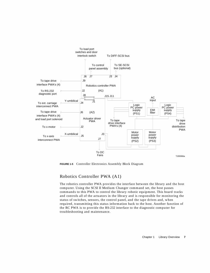
FIGURE 1-5 Controller Electronics Assembly Block Diagram
Robotics Controller PWA (A1)
The robotics controller PWA provides the interface between the library and the host
computer. Using the SCSI II Medium Changer command set, the host passes
commands to this PWA to control the library robotic equipment. This board tracks
and controls all of the actuators in the library and is responsible for monitoring the
status of switches, sensors, the control panel, and the tape drives and, when
required, transmitting this status information back to the host. Another function of
the RC PWA is to provide the RS-232 interface to the diagnostic computer for
troubleshooting and maintenance.
TJ00066a
To DIFF-SCSI bus
bus (optional)To SE-SCSI
PWA's (4)drive interface
To tape
Robotics controller PWA
interface PWA's (4)and load port solenoid
To x-motor
interconnect PWATo x-axis
Actuator driver
X-umbilicalJ5
J2
FansTo DC
J7
PWA
J3
To ext. carriage
interface PWA's (4)To tape drive
diagnostic port
interconnect PWA
To tape drive
To RS-232
switches and doorinterlock switch
J6
J8
Y-umbilical
J6
J4
J2
J9
(A1)
(A2)
J1
J15 J11
panel assemblyTo control
J7 J3
To load port
Motorpowersupply(PS2) (PS3)
Motorpowersupply
To tape
distribution
PC powerLogic
PC powersupply(PS1)
J4
input
EMIfilter
AC
supply(PS4)
Logic
PWA
drive
8 Sun Enterprise Tape Library 7/3500 Field Service Manual • July 1997
Actuator Driver PWA (A2)
The actuator driver PWA drives the library robotic mechanisms by using low-level
signal commands. This PWA provides the following functions:
■ Shunt over-voltage protection (OVP) regulator
■ X-axis motor interface
■ Y-axis motor interface
■ Extension motor interface
■ Tape drive handle motor interface
■ Load port lockout solenoid interface
Shunt OVP
The shunt OVP regulator on the actuator driver board serves two functions:
■ Over-voltage protection of the motor power supply
■ Rapid discharge of +48 VDC and +24 VDC in the event of a fault condition
The OVP regulator “shunts” to ground any regenerated current that create a voltage
fluctuation above 51.5 VDC. Therefore, the +48 VDC supply line is regulated to
below +51.5 VDC. A fault condition results in the rapid discharge of the motor bus.
For example, a fault condition occurs when the door is opened, the STOP switch is
pressed, the microprocessor watchdog times out, or when the +5V or +12V is out of
regulation. A fault condition immediately shuts down all actuators and rapidly
discharges the motor bus voltages within 100 milliseconds.
X-Axis Motor Interface
The x-axis motor interface on the actuator driver PWA receives open-loop low-level
step, direction, and current commands from the robotics controller. This PWA
amplifies and synthesizes the command signal to provide a high current two-phase
microstepping drive signal to the x-axis stepper motor.
Y-Axis Motor Interface
The y-axis motor interface on the actuator driver PWA receives open-loop low-level
step, direction, and current commands from the robotics controller. The PWA
amplifies and synthesizes the command signal to provide a high current two-phase
microstepping drive signal to the y-axis stepper motor.
Chapter 1 Library Overview 9
Extension Motor Interface
The extension motor interface on the actuator driver PWA receives closed-loop low -
level analog current control commands from the robotics controller. This PWA
amplifies the command signal to provide a moderate current drive signal to the
extension brush motor.
Load Port Lockout Solenoid Interface
The load port lockout solenoid interface on the actuator driver PWA receives a low-
level enable control command from the robotics controller and, in turn, provides an
open loop pull-in and hold current to the load port solenoid.
Tape Drive Handle Motor Interface
The tape drive handle motor interface on the actuator driver PWA receives open
loop low level full-stepping current control command from the robotics controller
and amplifies the command signal to provide a moderate current two-phase drive
signal to the tape drive handle stepper motor. The tape drive handle motor drives
are multiplexed, therefore, only one motor can be driven at any one time.
Power Supplies
The library uses two different power supplies types which are located on the CEA.
Logic PC Power Supplies
Each logic PC power supply produces 326 watts with automatic ranging to a 115
VAC or 230 VAC input at 50/60 Hz. Outputs of +5 VDC and ±12 VDC are used to
provide logic power for the library PWAs and the tape drives.
Motor Bus Power Supplies
Each motor bus power supply produces 110 watts with automatic ranging to 115
VAC or 230 VAC input at 50/60 Hz. The outputs of each power supply are
connected in series to provide +24 VDC and +48 VDC motor busses for the actuator
driver PWA (A2).
10 Sun Enterprise Tape Library 7/3500 Field Service Manual • July 1997
Extension Axis Assembly
The extension axis assembly (EAA) is located on the left side of the library. The EAA
consists of the extension axis assembly and the gripper assembly mounted on the
extension platform. FIGURE 1-6 shows the location of the components and FIGURE 1-7
shows the simplified block diagram. The individual components are discussed in the
paragraphs that follow.
FIGURE 1-6 Extension Axis Assembly
TA00050b
Extension axis drive belt
Gripper interconnect PWA
Gripper motor
Extension home sensor
Y-axis confirmation sensor
Gripper umbilical
Extension platform
Chapter 1 Library Overview 11
FIGURE 1-7 Extension Axis Assembly Block Diagram
Extension Drive Motor and Belt
The extension drive motor is located at the front of the extension axis assembly. The
extension belt is located along the left edge of the extension axis assembly. The
24 VDC brush motor engages the belt, while the belt drives the cartridge gripper
assembly forward and backward on the extension rail of the extension axis assembly.
Extension Carriage Interconnect PWA
The extension carriage interconnect PWA is located on the bottom of the extension
axis assembly. The extension home sensor is mounted to the extension carriage
interconnect PWA. This PWA receives low-level signals from the extension motor
encoder, CIG sensors, bar code scanner, gripper sensors, extension home and y-axis
sensors. The low-level signals are buffered and driven down the Y-umbilical to the
actuator driver were they are eventually received at the robotics controller. This
PWA also acts as an distribution/interconnection point for gripper and extension
motor drives from the actuator driver through the Y-umbilical.
Extension Motor (M3) and Encoder
The extension motor is a +24 VDC/2A brush motor with a 10:1 gearhead. The motor
drives the extension belt, which in turn, drives the cartridge gripper assembly
forward and backward on the extension rail of the extension axis assembly.
The extension motor encoder mounts on the bottom of the extension brush motor.
The encoder is a 100 lines per revolution, two channel encoder, which gives position
feedback to the robotics controller.
J3
J3
J5J1
J2
J4
J5J4
J3
J2
(S2)Conf. SensorY-Axis
Gripper Motor
Scanner PWABar Code
PWACIG RX
PWACIG TX
(A6)
InterconnectGripper
(A5)
InterconnectExtension Axis Extension
Motor(M3)
TA00035a
PWATo ActuatorDriver PWA
Y-Umbilical
Gripper Umbilical
PWA

12 Sun Enterprise Tape Library 7/3500 Field Service Manual • July 1997
Gripper Interconnect PWA
The gripper interconnect PWA acts as a distribution/interconnection point for
signals from the gripper motor, CIG transmitter PWA, CIG receiver PWA, and bar
code scanner PWA to the gripper umbilical. The gripper open and closed sensors are
mounted to the Gripper interconnect PWA and also are routed to the gripper
umbilical. The gripper umbilical plugs into the extension carriage interconnect PWA,
which buffers the low-level signals and routes all signals down the Y-umbilical.
Gripper Motor
The gripper motor raises and lowers the upper gripper jaw. The gripper motor is a
2-phase stepper motor with 1.8 degrees (0.005 inches) per step resolution.
Cartridge-In-Gripper Receiver PWA
The cartridge-in-gripper (CIG) receiver PWA contains two synchronous photo-
detectors located at the front and back of the lower jaw. The CIG receivers are
positioned to enable the robotics controller PWA to determine if a tape cartridge is
fully gripped. If the front CIG receiver only is occluded, the cartridge is partially
gripped. If the front and rear CIG receivers are occluded, the cartridge is fully
gripped.
The outputs of each of the CIG receivers are ORed together to drive a red LED
transmitter as part of synchronous break-beam detection system. The pulsed light
from the CIG transmitter shines across both CIG receiver sensors on the lower
gripper jaw.
Cartridge-In-Gripper Transmitter PWA
The CIG transmitter PWA contains one red LED that is driven by the CIG receiver
PWA as part of synchronous break-beam detection system. The light from the CIG
transmitter shines across both CIG receiver sensors, which are located at the front
and back of the lower gripper jaw.

Chapter 1 Library Overview 13
Bar Code Scanner PWA
The bar code scanner PWA is built inside the gripper assembly and detects bar codes
between the upper and lower gripper jaws.
The bar code scanner uses an IR (IR viewing scope is required to see the light) or red
LED that is focused to reflect off the bar code label surface and converge through
receiver optics on a photodetector. The output of the photodetector is amplified and
conditioned to produce a digital signal. The digital signal is decoded on the robotics
controller PWA as bar codes or for calibration.
The bar code scanner uses reflective targets on each bin column and reflective
features on each tape drive bezel to determine X andY positions during calibration.
During an inventory, the bar code scanner reads the bar code labels on the cartridges
and sends a digital signal that is decoded as a bar code on the robotics controller.
Y-Axis Confirmation Sensor (S2)
The Y-Axis confirmation sensor is located on the extension axis assembly. The y-axis
sensor provides feedback to the robotics controller for confirmation on position and
allows the vertical axis to home base on slots in the vertical rail.
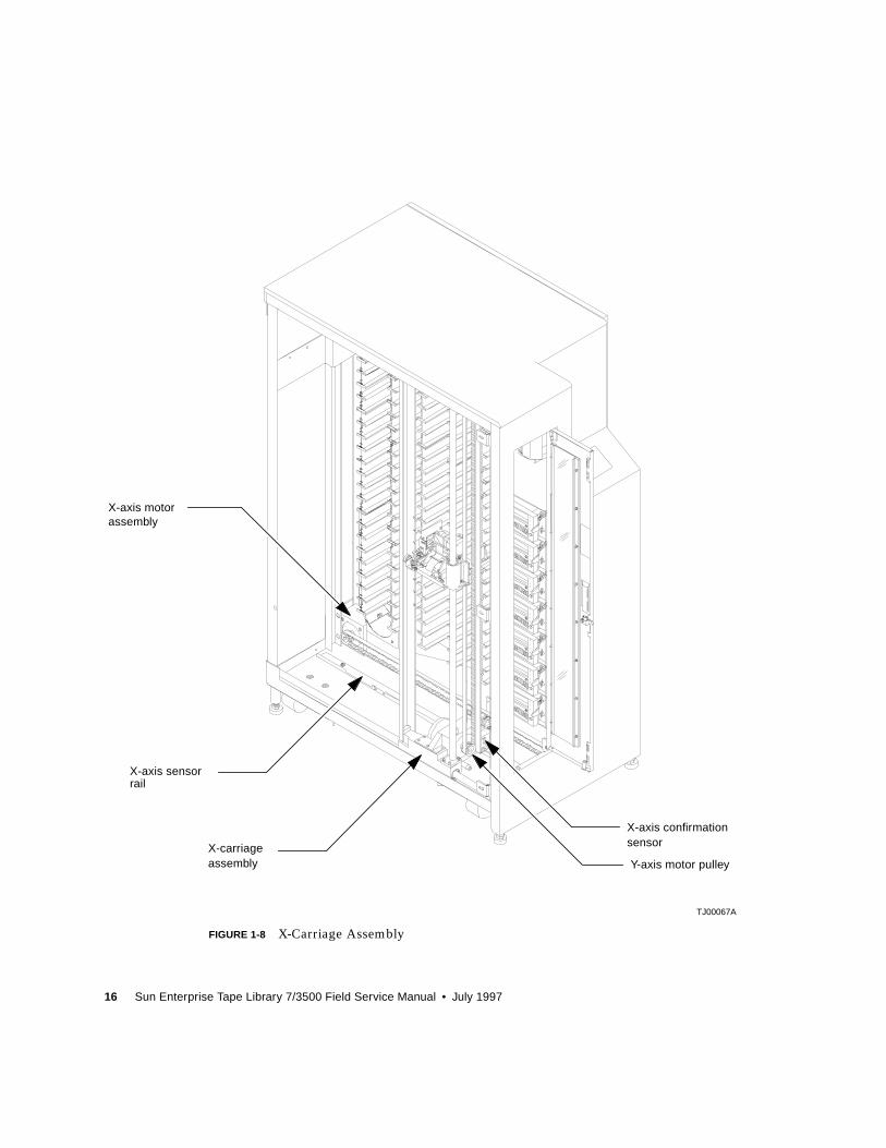
X-Carriage Assembly
The x-carriage assembly consists of the x-carriage, the x-axis interconnect PWA, and
the y-axis motor assembly. FIGURE 1-8 on page 16 shows the location of the
components. The individual components are discussed in the following paragraphs.
The x-carriage assembly rides on the lower horizontal rail and provides mounts for
the vertical rail. It also contains the y-axis motor and the x-carriage interconnect
PWA that provides an attachment point and strain relief for the x-umbilical.
14 Sun Enterprise Tape Library 7/3500 Field Service Manual • July 1997
X-Carriage
The x-carriage is a structure that rides on the lower horizontal rail, provides and
mounts for the vertical rail. The x-carriage also mounts the y-axis motor, and mounts
the x-carriage interconnect PWA.
X-Axis Interconnect PWA
The x-axis interconnect PWA is located on the rear of the x-carriage assembly as
viewed from the left side of the system. The x-carriage interconnect PWA provides
an attachment point and strain relief for the x-umbilical. Signals from the x-axis
confirmation sensor and drive for the y-axis motor are delivered to the x-axis
interconnect through the x-umbilical.
The x-axis interconnect PWA receives a signal from the x-axis confirmation sensor,
buffers and drives it down the x-umbilical to the actuator driver were it is received
at the robotics controller. The x-axis interconnect PWA acts as an distribution/
interconnection point for the y-axis motor from the actuator driver through the
y-umbilical cable.
X-Axis Confirmation Sensor
The x-axis confirmation sensor is located on the x-carriage assembly. The sensor
confirms bin and tape drive column position to the robotics controller PWA. The
sensor enables the horizontal axis to home using slots in the x-axis sensor rail
mounted on the bottom of the library frame.
Y-Axis Motor
The y-axis motor, mounted in the x-carriage assembly, is a two-phase stepper motor
which has 1.8 degrees (0.005 inches) per step resolution. One end of the motor shaft
holds a flanged pulley that engages the vertical drive belt. The opposite end is an
idler pulley. The y-axis motor is micro-stepped to provide accurate open loop
position control. The position loop is closed through the y-axis confirmation sensor
and flags.
The vertical drive belt, an open-ended belt (not a continuous loop), is driven by the
y-axis motor to propel the vertical carriage up and down the vertical rails. The y-axis
is held at each position, without the need for a counterweight, by the stepper motor.
Chapter 1 Library Overview 15
X-Axis Motor
The x-axis motor, mounted to the rear of the library, is a two-phase stepper motor
which has 1.8 degrees (0.005 inches) per step resolution. One end of the motor shaft
holds a flanged pulley that engages the horizontal drive belt. The opposite end is an
idler pulley. The x-axis motor is micro-stepped to provide accurate open loop
position control. The position loop is closed through the x-axis confirmation sensor
and flags.
The horizontal drive belt, an open-ended belt (not a continuous loop), is driven by
the x-axis motor to propel the x-carriage assembly along the horizontal rail.
16 Sun Enterprise Tape Library 7/3500 Field Service Manual • July 1997
FIGURE 1-8 X-Carriage Assembly
TJ00067A
X-carriage
X-axis motor
X-axis sensor
X-axis confirmation
Y-axis motor pulley
assembly
assembly
rail
sensor
Chapter 1 Library Overview 17
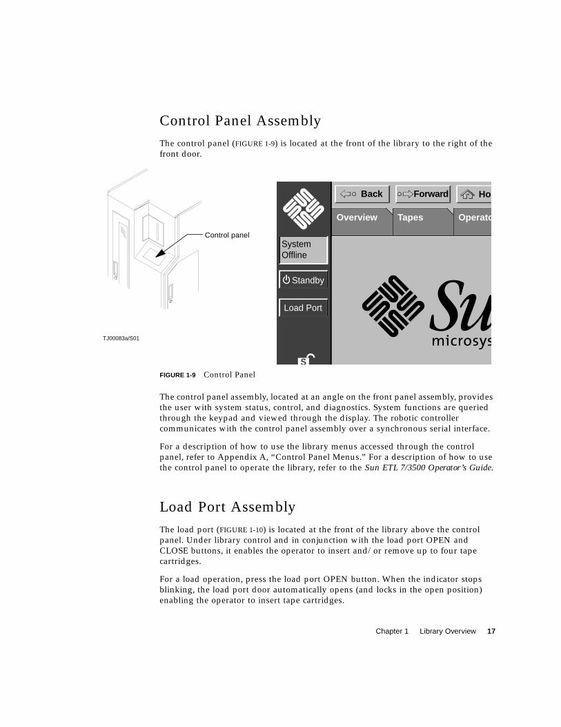
Control Panel Assembly
The control panel (FIGURE 1-9) is located at the front of the library to the right of the
front door.
FIGURE 1-9 Control Panel
The control panel assembly, located at an angle on the front panel assembly, provides
the user with system status, control, and diagnostics. System functions are queried
through the keypad and viewed through the display. The robotic controller
communicates with the control panel assembly over a synchronous serial interface.
For a description of how to use the library menus accessed through the control
panel, refer to Appendix A, “Control Panel Menus.” For a description of how to use
the control panel to operate the library, refer to the Sun ETL 7/3500 Operator’s Guide.
Load Port Assembly
The load port (FIGURE 1-10) is located at the front of the library above the control
panel. Under library control and in conjunction with the load port OPEN and
CLOSE buttons, it enables the operator to insert and/or remove up to four tape
cartridges.
For a load operation, press the load port OPEN button. When the indicator stops
blinking, the load port door automatically opens (and locks in the open position)
enabling the operator to insert tape cartridges.
Control panel
TJ00083a/S01
S
Load Port
Standby
HomBack Forward
SystemOffline
TapesOverview Operato
1
18 Sun Enterprise Tape Library 7/3500 Field Service Manual • July 1997
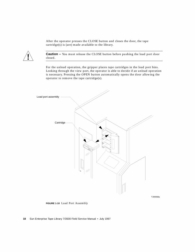
After the operator presses the CLOSE button and closes the door, the tape
cartridge(s) is (are) made available to the library.
Caution – You must release the CLOSE button before pushing the load port door
closed.
For the unload operation, the gripper places tape cartridges in the load port bins.
Looking through the view port, the operator is able to decide if an unload operation
is necessary. Pressing the OPEN button automatically opens the door allowing the
operator to remove the tape cartridge(s).
FIGURE 1-10 Load Port Assembly
TJ00068a
Load port assembly
Cartridge
Chapter 1 Library Overview 19
Load Port Switch 1
Load port switch 1 is located on the left bottom side of the load port assembly while
looking at the library from its left side. Load port switch 1 indicates that the load
port door is open when actuated. The load port switch 1 is a lever operated
mechanical micro-switch.
Load Port Switch 2
Load port switch 2 is located on the right bottom side of the load port assembly
while looking at the library from its left side. Load port switch 2 indicates that the
load port door is closed when actuated. The load port switch 2 is a lever operated
mechanical micro-switch.
Front Door Interlock Switch
The front door interlock switch is located at the bottom of the front door. This switch
is a magnetic reed switch that comprises a magnet (attached to the front door) and a
read relay (attached to the front panel assembly). When the magnet is within 0.5
inches of the read relay the switch contact closes. Motor power is shut down when
the front door is opened.
Drive Access Door Interlock Switch
The drive access door interlock switch is located on the right panel. This switch is a
magnetic reed switch that comprises a magnet (attached to the front door) and a
read relay (attached to the front panel assembly). When the magnet is within 0.5
inches of the read relay the switch contact closes. Motor power is shut down when
the front door is opened.
Storage Array Door Interlock Switch
The storage array door interlock switch is located on the left panel. This switch is a
magnetic reed switch that comprises a magnet (attached to the front door) and a
read relay (attached to the front panel assembly). When the magnet is within
0.5 inches of the read relay the switch contact closes. Motor power is shut down
when the front door is opened.

20 Sun Enterprise Tape Library 7/3500 Field Service Manual • July 1997
Load Port Lockout Solenoid
The load port lockout solenoid is located on top of the load port assembly. When the
load port lockout solenoid is actuated, the solenoid plunger is raised, unlocking the
load port mechanism, enabling the load port to slide freely open or closed. The load
port solenoid is immediately disengaged by the robotics controller, after the load
port mechanism moves off either limit switch, to enable the load port solenoid
plunger to fall back into a lockout point when the load port mechanism reaches an
open or closed position.
Tape Drive Assembly
A tape drive assembly consists of a tape drive, handle drive assembly (including the
stepper motor), and tape drive interface PWA mounted on a tape drive tray. There
can be up to seven tape drive assemblies in a library.
Tape Drives
When viewed from the left-side of the library, up to seven SCSI tape drives are
located in the front of the library just below the load port assembly. On the rear of
each tape drive is a tape drive interface PWA.
Handle Drive Assembly
A stepper motor assembly is mounted on the right side of each tape drive that is
used to electromechanically open and close the tape drive door. The handle stepper
motor is a two-phase stepper motor, which has 0.68 degrees per step resolution at
the tape drive door.
Tape Drive Interface PWA
The tape drive interface PWA plugs into the rear of each tape drive. It acts as an
interconnect/distribution point for RS-422 control/status and SCSI ID settings from
the robotics controller, +5V and +12V from the logic power supply, tape drive handle
door closed sensor inputs to the robotics controller, and handle stepper motor drives
from the actuator driver. This aids in minimizing cabling to each tape drive.
The tape drive interface PWA allows for convenient bussing and configuration of the
tape drives to external SCSI hosts. Each tape drive can be installed on the same or
different busses by using jumper cables between the PWAs.

Chapter 1 Library Overview 21
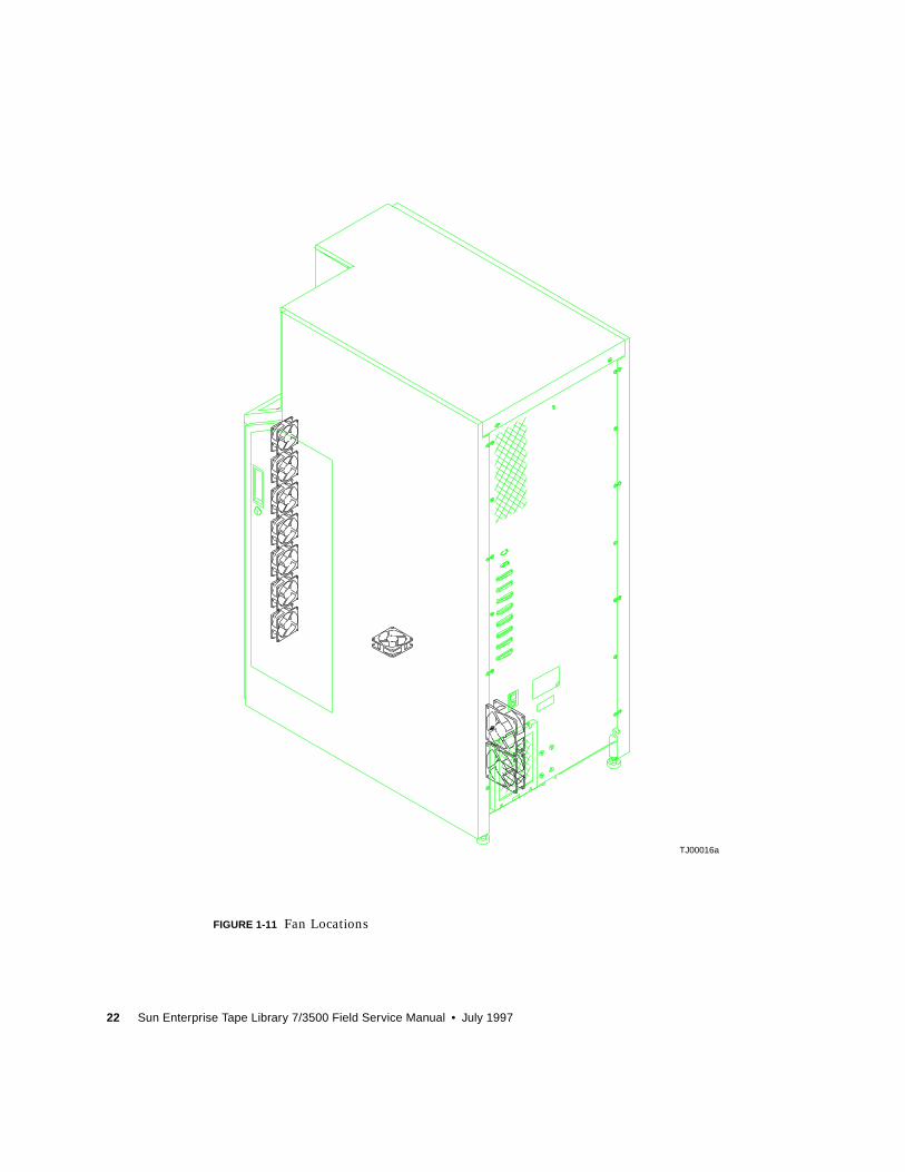
Fans
The library uses up to ten DC fans for cooling. FIGURE 1-11 shows their location. A
filter on the rear of the library is part of the fan assembly and requires scheduled
routine maintenance.
22 Sun Enterprise Tape Library 7/3500 Field Service Manual • July 1997
FIGURE 1-11 Fan Locations
TJ00016a
23
CHAPTER 2
Preventive Maintenance
This chapter provides guidelines and procedures for aligning, adjusting, cleaning,
and lubricating specific components of the library.
Caution – All preventative maintenance procedures must be performed by an
authorized field service engineer (FSE).
Preventive Maintenance Schedule
Preventive maintenance (PM) for the library should only be performed by an
authorized field service engineer (FSE). TABLE 2-1 lists the type of PM required by the
library and specifies the maximum time frame between preventive maintenance.
Note – The first FSE PM is performed during initial installation.
TABLE 2-1 Preventive Maintenance Guidelines
PM Required Maximum Time Frame
Cleaning and lubricating the rails and rollers every 12 months
Cleaning and lubricating the gripper assembly every 12 months
Checking and adjusting belt tensions and rollers every 12 months
Cleaning the fan filter every 12 months
Cleaning the tape drives every 12 months
24 Sun Enterprise Tape Library 7/3500 Field Service Manual • July 1997
Required Tools and Supplies
The following tools are required to perform preventative maintenance:
■ Phillips screwdrivers, #1 and #2
■ Flat-bladed screwdrivers, assorted sizes
The following items from the ETL Servoce Kit are required to perform preventtive
maintenance:
■ 1 container permeable lubricant
■ 1 package swabs
■ 1 package lint-free cloths
■ X-Y axis belt tension gauge
■ Extension axis belt tension gauge
▼ To Prepare for Preventive Maintenance
1. Remove power from the library.
Caution – DO NOT disconnect the power cord from facility power or the library.
The power cord is the only means of grounding the chassis and helping to prevent
electrostatic discharge (ESD) damage.
2. Remove the top and left cosmetic panels as shown in “Removing the CosmeticPanels” on page 90.
3. Connect your ESD wrist grounding strap to the closest grounding socket on theframe of the library.
Cleaning Procedures
The first step of the preventive maintenance is to clean the fan filter and the moving
mechanical components of the library. Inspect each library component outlined
below for dust, debris, damage, or wear.

Chapter 2 Preventive Maintenance 25
▼ To Clean the Fan Filter
See FIGURE 2-1.
1. Remove the four Phillips screws retaining the fan filter cover, located in the rearof the library.
2. Remove the fan filter cover and the fan filter from the library.
3. Clean the filter and fan louvers on the rear of the library with a vacuum.
4. Reinstall fan filter and frame to the rear of the library.
26 Sun Enterprise Tape Library 7/3500 Field Service Manual • July 1997
FIGURE 2-1 Fan Filter
▼ To Clean the Rails
See FIGURE 2-2.
TJ00070a
Fan filter cover
Fan filter
Filter and fan louvers

Chapter 2 Preventive Maintenance 27
1. Lightly dampen a cloth (supplied in PM kit) with isopropyl alcohol and rub thelength of the x-axis rail and the y-axis rail to remove all dust and debris.
2. Repeat if necessary.
28 Sun Enterprise Tape Library 7/3500 Field Service Manual • July 1997
FIGURE 2-2 X-Axis and Y-Axis Rails
TJ00054a
X-axis rail
X-axis assembly
Y-axis assembly
Extension axis assembly
Y-axis rail
Chapter 2 Preventive Maintenance 29
▼ To Clean the Extension Axis
See FIGURE 2-3.
1. Remove the ESD cover.
2. Lightly dampen a cloth (supplied in PM kit) with isopropyl alcohol.
3. Remove all dust and debris from the:
■ Extension axis rail
■ Gripper cross shaft
■ Extension axis follower rail on the wear surface
Caution – Do NOT apply lubricant to the extension axis follower rail. Applying
lubricant to the extension axis follower rail damages it.
■ Gripper jaw inner surfaces
Note – Use a can of compressed air to blow dust off of the CIG receivers.
4. Repeat if necessary.
30 Sun Enterprise Tape Library 7/3500 Field Service Manual • July 1997
FIGURE 2-3 Extension Axis Assembly
▼ To Clean the Tape Drives
See FIGURE 2-4.
1. Lightly dampen a cloth (supplied in PM kit) with isopropyl alcohol.
2. Remove all dust and debris from the tape drive receiver.
Extension axis rail
Gripper cross shaft
Extension axis follower rail
Gripper jaw inner surfaces
Extension axis
Extensionaxisassembly
TA00027a/TJ00071a
follower rail
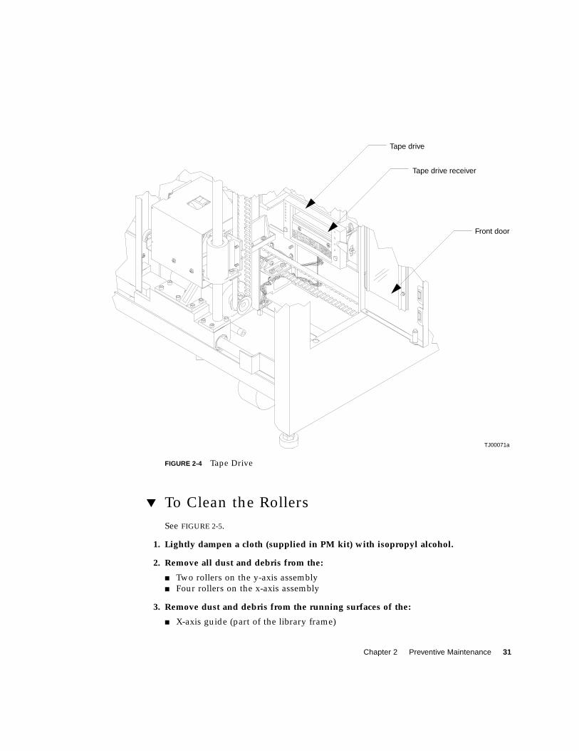
Chapter 2 Preventive Maintenance 31
FIGURE 2-4 Tape Drive
▼ To Clean the Rollers
See FIGURE 2-5.
1. Lightly dampen a cloth (supplied in PM kit) with isopropyl alcohol.
2. Remove all dust and debris from the:
■ Two rollers on the y-axis assembly
■ Four rollers on the x-axis assembly
3. Remove dust and debris from the running surfaces of the:
■ X-axis guide (part of the library frame)
Tape drive receiver
Tape drive
Front door
TJ00071a
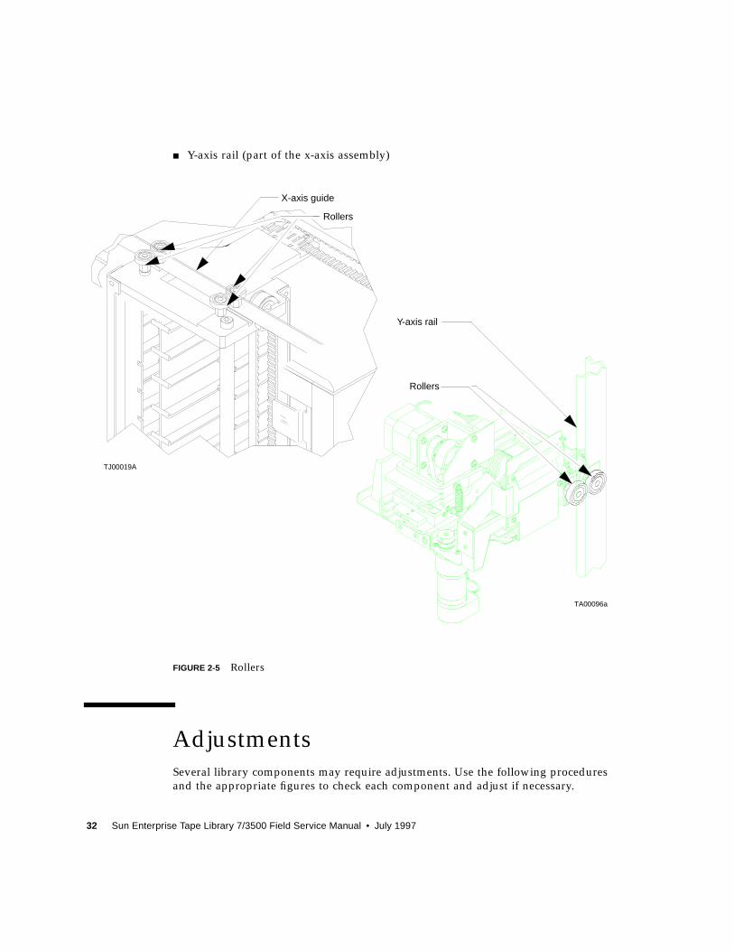
32 Sun Enterprise Tape Library 7/3500 Field Service Manual • July 1997
■ Y-axis rail (part of the x-axis assembly)
FIGURE 2-5 Rollers
Adjustments
Several library components may require adjustments. Use the following procedures
and the appropriate figures to check each component and adjust if necessary.
Rollers
Y-axis rail
Rollers
X-axis guide
TA00096a
TJ00019A
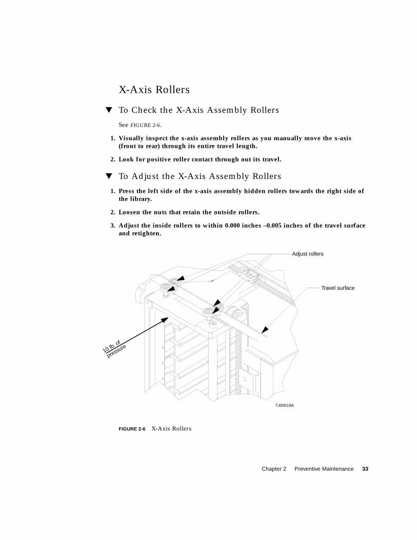
Chapter 2 Preventive Maintenance 33
X-Axis Rollers
▼ To Check the X-Axis Assembly Rollers
See FIGURE 2-6.
1. Visually inspect the x-axis assembly rollers as you manually move the x-axis(front to rear) through its entire travel length.
2. Look for positive roller contact through out its travel.
▼ To Adjust the X-Axis Assembly Rollers
1. Press the left side of the x-axis assembly hidden rollers towards the right side ofthe library.
2. Loosen the nuts that retain the outside rollers.
3. Adjust the inside rollers to within 0.000 inches –0.005 inches of the travel surfaceand retighten.
FIGURE 2-6 X-Axis Rollers
Travel surface
10 lb. of
pressure
Adjust rollers
TJ00019A
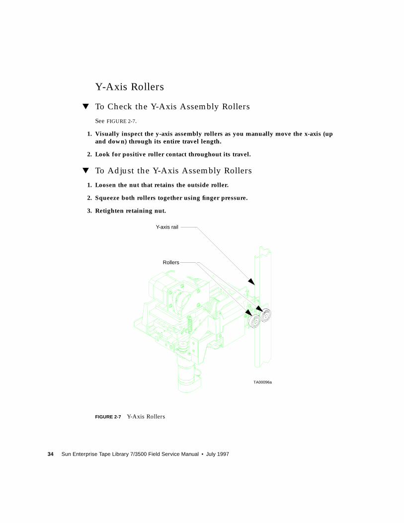
34 Sun Enterprise Tape Library 7/3500 Field Service Manual • July 1997
Y-Axis Rollers
▼ To Check the Y-Axis Assembly Rollers
See FIGURE 2-7.
1. Visually inspect the y-axis assembly rollers as you manually move the x-axis (upand down) through its entire travel length.
2. Look for positive roller contact throughout its travel.
▼ To Adjust the Y-Axis Assembly Rollers
1. Loosen the nut that retains the outside roller.
2. Squeeze both rollers together using finger pressure.
3. Retighten retaining nut.
FIGURE 2-7 Y-Axis Rollers
Rollers
Y-axis rail
TA00096a
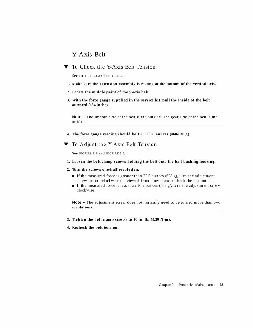
Chapter 2 Preventive Maintenance 35
Y-Axis Belt
▼ To Check the Y-Axis Belt Tension
See FIGURE 2-8 and FIGURE 2-9.
1. Make sure the extension assembly is resting at the bottom of the vertical axis.
2. Locate the middle point of the y-axis belt.
3. With the force gauge supplied in the service kit, pull the inside of the beltoutward 0.54 inches.
Note – The smooth side of the belt is the outside. The gear side of the belt is the
inside.
4. The force gauge reading should be 19.5 ± 3.0 ounces (468-638 g).
▼ To Adjust the Y-Axis Belt Tension
See FIGURE 2-8 and FIGURE 2-9.
1. Loosen the belt clamp screws holding the belt onto the ball bushing housing.
2. Turn the screws one-half revolution:
■ If the measured force is greater than 22.5 ounces (638 g), turn the adjustment
screw counterclockwise (as viewed from above) and recheck the tension.
■ If the measured force is less than 16.5 ounces (468 g), turn the adjustment screw
clockwise.
Note – The adjustment screw does not normally need to be turned more than two
revolutions.
3. Tighten the belt clamp screws to 30 in. lb. (3.39 N-m).
4. Recheck the belt tension.
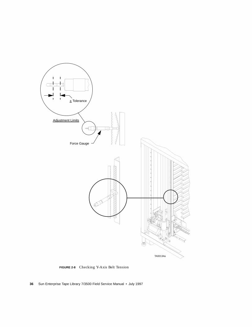
36 Sun Enterprise Tape Library 7/3500 Field Service Manual • July 1997
FIGURE 2-8 Checking Y-Axis Belt Tension
+ Tolerance
Force Gauge
Adjustment Limits
TA00134a
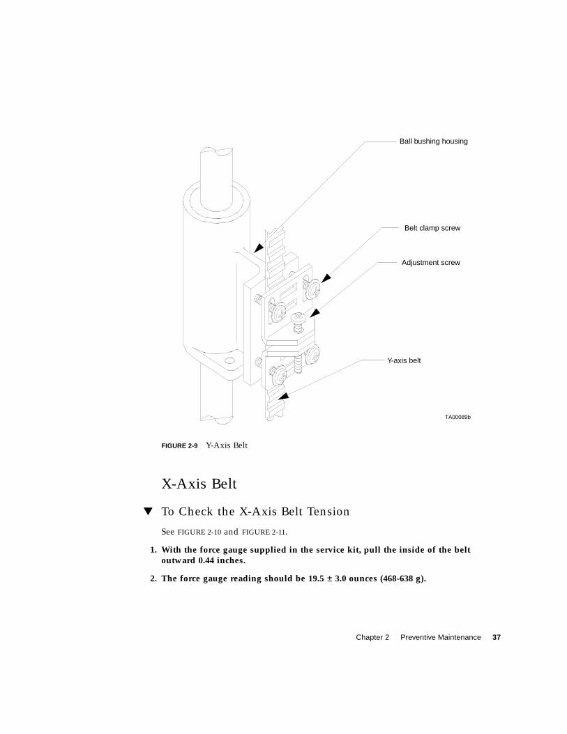
Chapter 2 Preventive Maintenance 37
FIGURE 2-9 Y-Axis Belt
X-Axis Belt
▼ To Check the X-Axis Belt Tension
See FIGURE 2-10 and FIGURE 2-11.
1. With the force gauge supplied in the service kit, pull the inside of the beltoutward 0.44 inches.
2. The force gauge reading should be 19.5 ± 3.0 ounces (468-638 g).
TA00089b
Adjustment screw
Y-axis belt
Belt clamp screw
Ball bushing housing
38 Sun Enterprise Tape Library 7/3500 Field Service Manual • July 1997
▼ To Adjust the X-Axis Belt Tension
See FIGURE 2-10 and FIGURE 2-11.
Note – The smooth side of the belt is the outside. The gear side of the belt is the
inside.
1. Loosen the belt clamp screws holding the belt onto the motor mounting verticalbracket.
2. Turn the screws one-half revolution:
■ If the measured force was greater than 22.5 ounces (638 g), turn the adjustment
screw counterclockwise (as viewed from above) and recheck the tension.
■ If the measured force was less than 16.5 ounces (468 g), turn the adjustment screw
clockwise.
Note – The adjustment screw does not normally need to be turned more than two
revolutions.
3. Tighten the belt clamp screws to 30 in. lb. (3.39 N-m).
4. Recheck the belt tension.
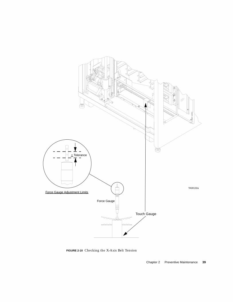
Chapter 2 Preventive Maintenance 39
FIGURE 2-10 Checking the X-Axis Belt Tension
Force Gauge
Force Gauge Adjustment Limits
+ Tolerance
TA00132a
Touch Gauge
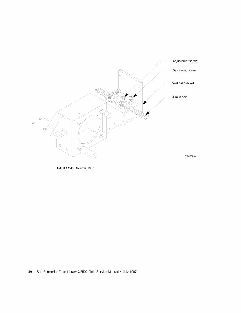
40 Sun Enterprise Tape Library 7/3500 Field Service Manual • July 1997
FIGURE 2-11 X-Axis Belt
TA00088a
X-axis belt
Adjustment screw
Vertical bracket
Belt clamp screw
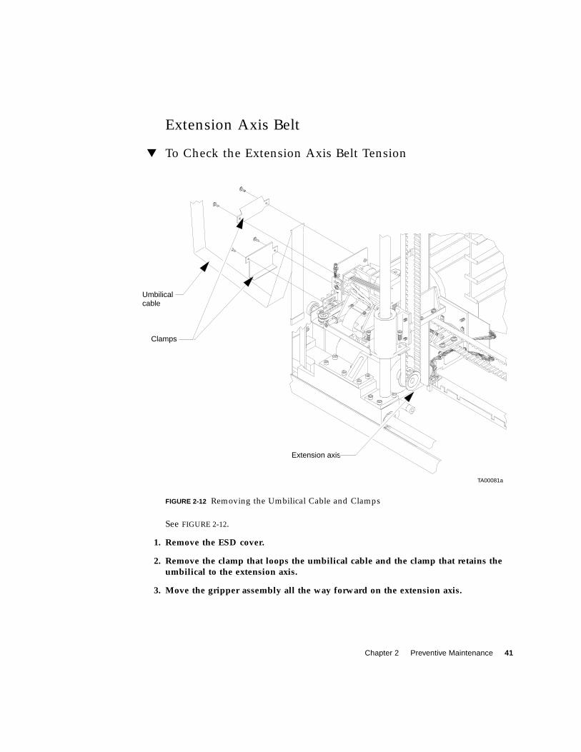
Chapter 2 Preventive Maintenance 41
Extension Axis Belt
▼ To Check the Extension Axis Belt Tension
FIGURE 2-12 Removing the Umbilical Cable and Clamps
See FIGURE 2-12.
1. Remove the ESD cover.
2. Remove the clamp that loops the umbilical cable and the clamp that retains theumbilical to the extension axis.
3. Move the gripper assembly all the way forward on the extension axis.
TA00081a
Clamps
Umbilical
Extension axis
cable
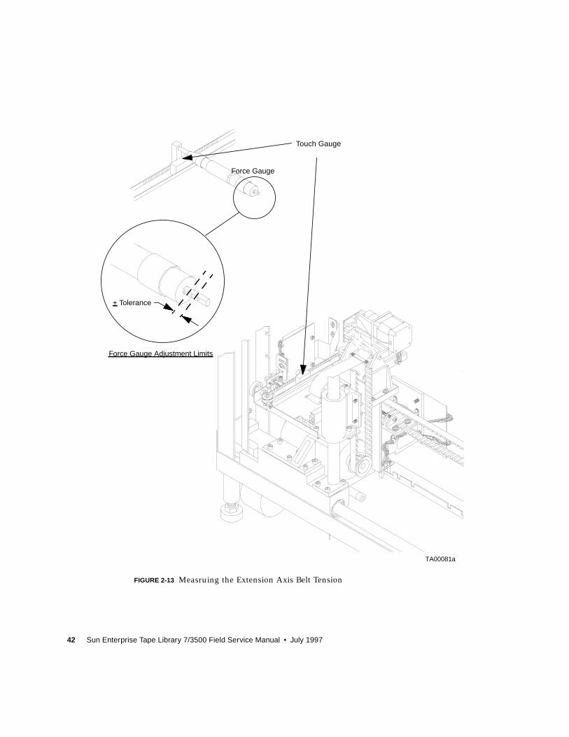
42 Sun Enterprise Tape Library 7/3500 Field Service Manual • July 1997
FIGURE 2-13 Measruing the Extension Axis Belt Tension
+ Tolerance
Force Gauge Adjustment Limits
Force Gauge
TA00081a
Touch Gauge
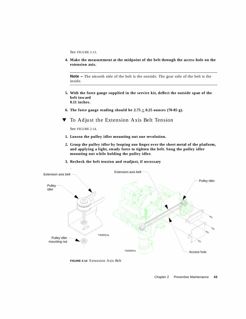
Chapter 2 Preventive Maintenance 43
See FIGURE 2-13.
4. Make the measurement at the midpoint of the belt through the access hole on theextension axis.
Note – The smooth side of the belt is the outside. The gear side of the belt is the
inside.
5. With the force gauge supplied in the service kit, deflect the outside span of thebelt inward0.11 inches.
6. The force gauge reading should be 2.75 + 0.25 ounces (70-85 g).
▼ To Adjust the Extension Axis Belt Tension
See FIGURE 2-14.
1. Loosen the pulley idler mounting nut one revolution.
2. Grasp the pulley idler by looping one finger over the sheet metal of the platform,and applying a light, steady force to tighten the belt. Snug the pulley idlermounting nut while holding the pulley idler.
3. Recheck the belt tension and readjust, if necessary
.
FIGURE 2-14 Extension Axis Belt
TA00097a
Pulley idler
Pulley
Extension axis belt
Access hole
Extension axis belt
Pulley idler
TA00021a
mounting nut
idler
44 Sun Enterprise Tape Library 7/3500 Field Service Manual • July 1997
Lubrication
There are several library components that require lubrication. Use the following
procedures and the appropriate figures to lubricate each identified component.
▼ To Lubricate the X-Axis and Y-Axis Rails
See FIGURE 2-2 on page 28.
1. Lightly apply a very thin coating of permeable lubricant (supplied in PM kit) tothe length of the x-axis rail and the y-axis rail.
2. Move the x-axis and y-axis assemblies through their complete range of travel todistribute lubrication.
3. A light coating of lubricant should be present on the x-axis rail and the y-axis rail.Remove excess lubricant.
▼ To Lubricate the Extension Axis Rail and
Gripper Cross-Shaft
See FIGURE 2-3 on page 30.
1. Lightly apply a very thin coating of permeable lubricant (supplied in PM kit) tothe length of the extension axis rail.
2. Apply a small amount of lubricant to the gripper cross-shaft at its three contactpoints with the driver link and upper jam jaw.
Caution – Excess lubricant on the gripper cross-shaft may result in debris falling
onto the bar code scanner.
Caution – Do NOT apply lubricant to the extension axis follower rail. Applying
lubricant to the extension axis follower rail damages it.
3. A light coating of lubricant should be present on the extension axis rail and thegripper cross-shaft. Remove excess lubricant.
Chapter 2 Preventive Maintenance 45
Returning the Library to Operation
▼ To Return the Library to Operation
1. Replace the top and left cosmetic panels as described in “Removing the CosmeticPanels” on page 90.
2. Restore power to the library.
3. Calibrate the library as described in “To Calibrate Library Elements” on page 175.
After cleaning, adjusting, and lubricating internal components, the library must be
re-calibrated.
Caution – Neglecting to calibrate the library after performing maintenance may
cause damage to the library.

46 Sun Enterprise Tape Library 7/3500 Field Service Manual • July 1997
47
CHAPTER 3
Troubleshooting and Fault Isolation
This chapter provides the troubleshooting and fault isolation procedures for the
ETL 7/3500 library.
Maintenance Analysis Procedures(MAPs)
This section contains Maintenance Analysis Procedures (MAPs) for troubleshooting
library malfunctions. These procedures appear as flow charts, each with its own
descriptive heading.
▼ To Use These Procedures for Troubleshooting
1. Identify the problem as much as possible by symptom or error code. For moreinformation about error codes, see Appendix B, “Sense Data Values.”
2. Use the Contents page for this chapter to locate the section in this chapter thatrelates to the problem you identified.
3. Begin the troubleshooting analysis with the “Fault Isolation Entry MAP” onpage 48. This flow chart can help eliminate basic problems and direct you to otherflow charts.
4. Follow the flow charts step-by-step, testing the library after each corrective action.
While troubleshooting, you can also refer to the Sun ETL 7/3500 Diagnostic SoftwareUser’s Manual and Sun ETL 7/3500 Operator’s Guide.
5. Stop the troubleshooting procedure when the symptom or error disappears.
48 Sun Enterprise Tape Library 7/3500 Field Service Manual • July 1997
Fault Isolation Entry MAP
Is the library powered up?
Remove top, left, and, rightside panels (see “Removingthe Cosmetic Panels” onpage 90).
Suspect mechanicalproblem?
See “Mechanical InspectionEntry MAP” on page 50.
Turn power off.
Note all relevant data:a. Host informationb. Front panel status code
See “Power Entry MAP” onpage 61.
Suspect power or fuses?
Suspect control panel orload port?
See “Control Panel and LoadPort Debug MAP” onpage 56.
See “Online InitializationEntry MAP” on page 51.
See “Online Test EntryMAP” on page 52.
No
No
No
No
Yes
Yes
Yes
Yes
Chapter 3 Troubleshooting and Fault Isolation 49
Error Message Entry MAP
See TABLE B-1 on page 184. Usetest entry MAPs to locate anddebug for particular error code.
Open and close front door and placesystem online.
Passed online initialization tests? See “Diagnostic Test Entry MAP”on page 53.
See “Online Test Entry MAP” onpage 52.
No
Yes
50 Sun Enterprise Tape Library 7/3500 Field Service Manual • July 1997
Mechanical Inspection Entry MAP
1. Inspect drive belts2. Check for movement3. Check cartridges
Inspect and manually move thex-axis belt (see FIGURE 2-11 onpage 40).Belt and motor appear OK?
1.Tighten or adjust as required(see page 37).
2. Replace if required (seepage 116).
Inspect and manually move they-axis belt (see FIGURE 2-9 onpage 37).Belt and motor appear OK?
1. Tighten or adjust as required (seepage 35).
2. Replace if required (see page 118).
Inspect and manually move theextension axis belt (seeFIGURE 2-11 on page 40).Belt and motor appear OK?
Verify that the cartridges arefully seated in the storage array. Seat cartridges.
See “Fault Isolation EntryMAP” on page 48.
No
No
No
No
Yes
Yes
Yes
Yes
1. Tighten or adjust as required (seepage 41).
2.Replace if required (see “X-AxisDrive Belt” on page 116).
Chapter 3 Troubleshooting and Fault Isolation 51
Online Initialization Entry MAP
1. Power on self-test2. Home All sequence3. Inventory sequence
Power up the unit and place itonline.
Passed online initializationtests?
See “Online Test Entry MAP”on page 52.
Power down library.
See “Diagnostic Test EntryMAP” on page 53.
Yes
No
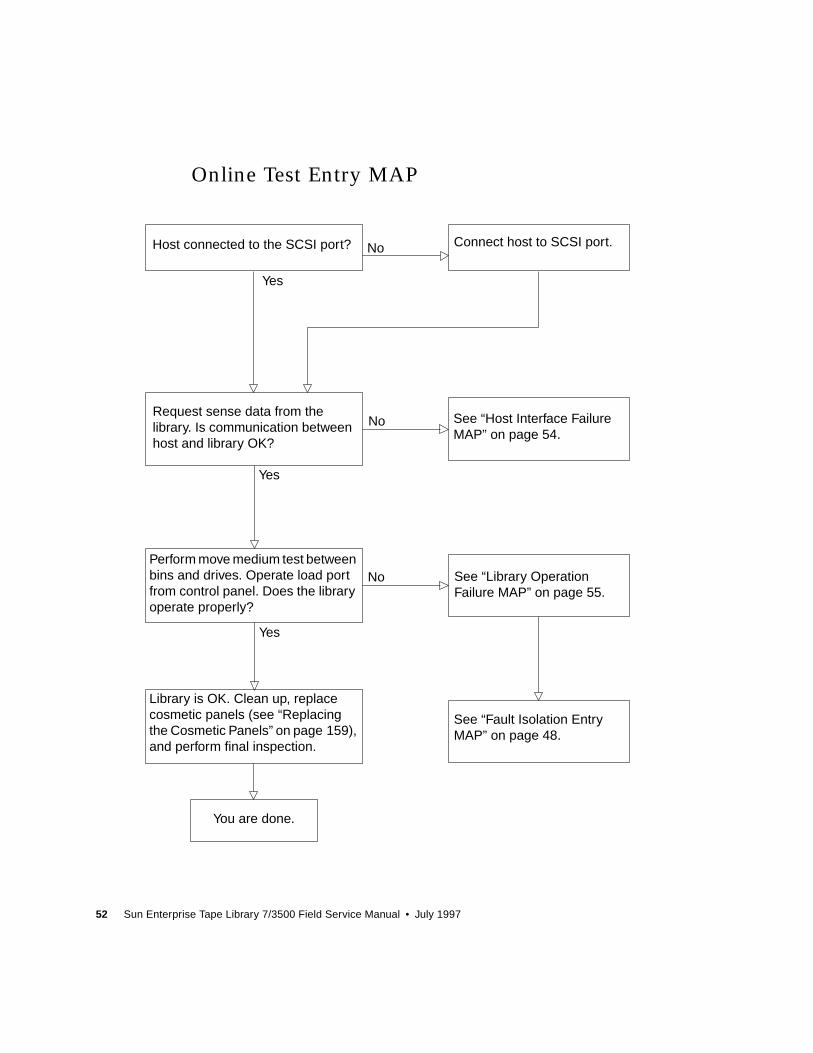
52 Sun Enterprise Tape Library 7/3500 Field Service Manual • July 1997
Online Test Entry MAP
Host connected to the SCSI port? Connect host to SCSI port.
Request sense data from thelibrary. Is communication betweenhost and library OK?
See “Host Interface FailureMAP” on page 54.
Perform move medium test betweenbins and drives. Operate load portfrom control panel. Does the libraryoperate properly?
See “Library OperationFailure MAP” on page 55.
Library is OK. Clean up, replacecosmetic panels (see “Replacingthe Cosmetic Panels” on page 159),and perform final inspection.
See “Fault Isolation EntryMAP” on page 48.
You are done.
No
No
No
Yes
Yes
Yes
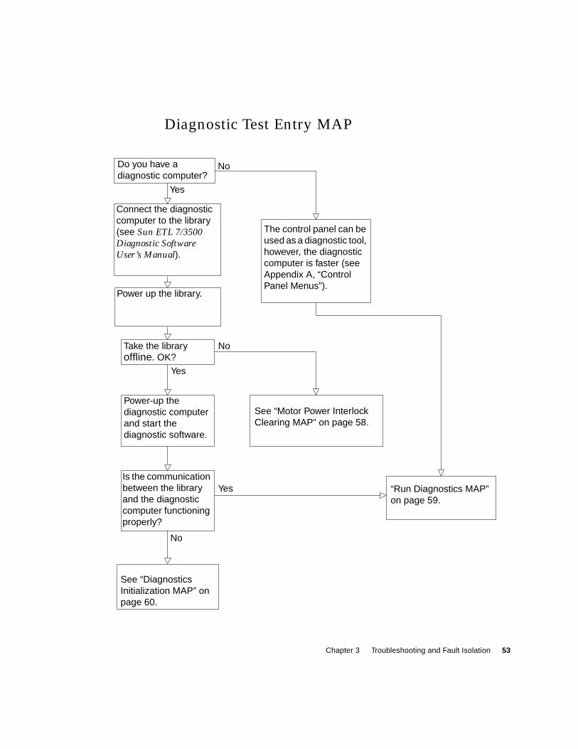
Chapter 3 Troubleshooting and Fault Isolation 53
Diagnostic Test Entry MAP
Do you have adiagnostic computer?
Connect the diagnosticcomputer to the library(see Sun ETL 7/3500Diagnostic SoftwareUser’s Manual).
Power up the library.
Take the libraryoffline. OK?
The control panel can beused as a diagnostic tool,however, the diagnosticcomputer is faster (seeAppendix A, “ControlPanel Menus”).
Power-up thediagnostic computerand start thediagnostic software.
Is the communicationbetween the libraryand the diagnosticcomputer functioningproperly?
See “Motor Power InterlockClearing MAP” on page 58.
“Run Diagnostics MAP”on page 59.
See “DiagnosticsInitialization MAP” onpage 60.
No
No
No
Yes
Yes
Yes
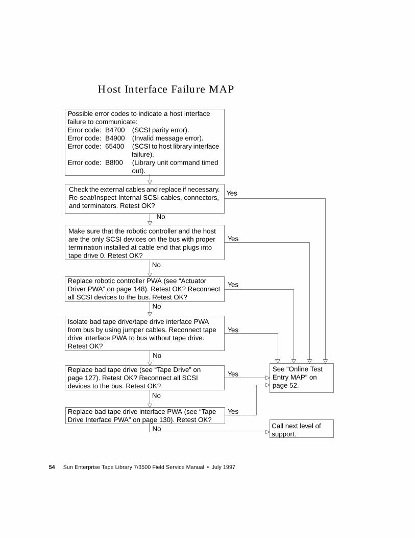
54 Sun Enterprise Tape Library 7/3500 Field Service Manual • July 1997
Host Interface Failure MAP
Replace bad tape drive interface PWA (see “TapeDrive Interface PWA” on page 130). Retest OK?
Possible error codes to indicate a host interfacefailure to communicate:Error code: B4700 (SCSI parity error).Error code: B4900 (Invalid message error).Error code: 65400 (SCSI to host library interface
failure).Error code: B8f00 (Library unit command timed
out).
Check the external cables and replace if necessary.Re-seat/Inspect Internal SCSI cables, connectors,and terminators. Retest OK?
Make sure that the robotic controller and the hostare the only SCSI devices on the bus with propertermination installed at cable end that plugs intotape drive 0. Retest OK?
Replace robotic controller PWA (see “ActuatorDriver PWA” on page 148). Retest OK? Reconnectall SCSI devices to the bus. Retest OK?
Isolate bad tape drive/tape drive interface PWAfrom bus by using jumper cables. Reconnect tapedrive interface PWA to bus without tape drive.Retest OK?
Replace bad tape drive (see “Tape Drive” onpage 127). Retest OK? Reconnect all SCSIdevices to the bus. Retest OK?
See “Online TestEntry MAP” onpage 52.
Call next level ofsupport.
No
No
No
No
No
No
Yes
Yes
Yes
Yes
Yes
Yes
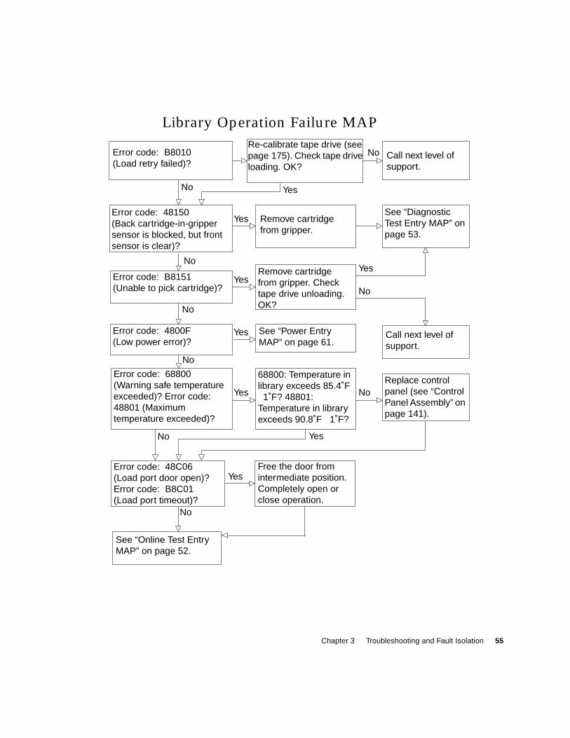
Chapter 3 Troubleshooting and Fault Isolation 55
Library Operation Failure MAP
Remove cartridgefrom gripper. Checktape drive unloading.OK?
Re-calibrate tape drive (seepage 175). Check tape driveloading. OK?
Error code: B8010(Load retry failed)?
Call next level ofsupport.
Remove cartridgefrom gripper.
See “DiagnosticTest Entry MAP” onpage 53.
Error code: 48150(Back cartridge-in-grippersensor is blocked, but frontsensor is clear)?
Error code: B8151(Unable to pick cartridge)?
Error code: 4800F(Low power error)?
See “Power EntryMAP” on page 61.
Call next level ofsupport.
Error code: 68800(Warning safe temperatureexceeded)? Error code:48801 (Maximumtemperature exceeded)?
Replace controlpanel (see “ControlPanel Assembly” onpage 141).
Error code: 48C06(Load port door open)?Error code: B8C01(Load port timeout)?
Free the door fromintermediate position.Completely open orclose operation.
See “Online Test EntryMAP” on page 52.
No
No
No
No
No
No
No
No
Yes
Yes
Yes
Yes
Yes
Yes
Yes
Yes
No
68800: Temperature inlibrary exceeds 85.4˚F 1˚F? 48801:
Temperature in libraryexceeds 90.8˚F 1˚F?
56 Sun Enterprise Tape Library 7/3500 Field Service Manual • July 1997
Control Panel and Load Port Debug MAP
Press STANDBY button toplace library in system offlinestate. Display shows “SystemOffline?”
Continue to load portoperation on page 57.
Place library in stop state,Display shows “LibraryStopped?”
Access several control panelscreens. Display changes andscreen is legible?
Call the next level ofsupport.
Replace robotic controller (see“Robotics Controller PWA” onpage 145). Retest OK?
Replace control panel (see“Control Panel Assembly”on page 141). Retest OK?
No
Yes
No
Yes
No
No
No
Yes
Yes
Chapter 3 Troubleshooting and Fault Isolation 57
Control Panel and Load Port Debug MAP (Cont.)
Lift up load portsolenoid piston.Manually open andclose load port.Diagnostics check ofsensors OK?
Continued from control panel operationon page 56. Load port operation.
Replace roboticscontroller (see“Robotics ControllerPWA” on page 145).Retest OK?
Replace control panel (see“Control Panel Assembly” onpage 141). Retest OK?
Is solenoidresistance 7-20ohms? Replacesolenoid (seepage 107).Retest OK?
Check for obstruction in load port.Open load port. Does display indicateload port is opening?
Does load portsolenoid audiblypop?
Check sensorcablingconnections.
Replace actuatordriver (seepage 148). RetestOK?
See “Online Test Entry MAP” on page 52. Call the next level of support.
No No No
NoNo
Yes
Yes
Yes
Yes
YesYes
No NoClose load port. Does display indicate loadport is closing?
Yes
Yes
NoNo
Yes
Replace controlpanel (see “ControlPanel Assembly” onpage 141). RetestOK?
58 Sun Enterprise Tape Library 7/3500 Field Service Manual • July 1997
Motor Power Interlock Clearing MAP
Replace robotics controller(see “Robotics ControllerPWA” on page 145). RetestOK?
1.Measure +5V on Tp2 of roboticscontroller, between+5.05V and+5.15V?
2.Measure +12V on output side of F3 ofrobotics controller, between +11.5Vand +12.5V?
1. Check stop switch.2. Check front door.3. Check +5V,+12V.4. Check microprocessor fault LED.5. Check PC power good signal.
Replace PC power supply and adjust (see“PC Logic Power Supply Assembly” onpage 151).
Stop LED is illuminated on controlpanel?
Depress stop switch.
Verify AC power is on.
Door open LED is illuminated on roboticscontroller?
See “Power Entry MAP” onpage 61.
Microprocessor fault LED is illuminatedon robotics controller?
PC Power Good signal on J15-pin1 ofrobotics controller is high? SeeFIGURE 3-1 on page 84.
See “Fault Isolation EntryMAP” on page 48.
Yes
Yes
Yes
Yes
Yes
No
No
No
No
No
Close front door.
Chapter 3 Troubleshooting and Fault Isolation 59
Run Diagnostics MAP
From the diagnosticcomputer or control panel,select and run the following:
Move Actuators Menu:SELF-TEST ALL passed?
See “Self-Test All MAP” onpage 62.
Move Actuators Menu:HOME ALL passed?
See “Home All MAP” onpage 64.
Config Menu: INITINVENTORY passed?
See “Inventory MAP” onpage 65.
Config Menu: CALIBRATEALL Passed?
See “Calibration MAP” onpage 66.
See “Online Test EntryMAP” on page 52.
No
No
No
No
Yes
Yes
Yes
Yes
60 Sun Enterprise Tape Library 7/3500 Field Service Manual • July 1997
Diagnostics Initialization MAP
Set up diagnostic computer.See Sun ETL 7/3500 DiagnosticSoftware User’s Manual.
Is the diagnostic computerinterface cable connected tothe DIAG PORT on thelibrary?
Connect the diagnosticcomputer interface cableport on the library.
Replace the diagnosticcomputer cable. Retest OK?
Call next level of support See “Run Diagnostics MAP”on page 59.
No
Yes
Yes
Yes
Yes
No
No
Replace robotics controller(see “Robotics ControllerPWA” on page 145). RetestOK?
Chapter 3 Troubleshooting and Fault Isolation 61
Power Entry MAP
See “Power SupplyEvaluation Entry MAP” onpage 69.
For: AC Power+5V Power+12V Power-12V Power+24V Power+48V Power
Check AC Power.OK?
Locate and connect tooperational AC power source.
See “Fault Isolation EntryMAP” on page 48.
See “Robotics Controller FuseIsolation Entry MAP” onpage 67.
Check robotics controllerfuses (see FIGURE 3-1 onpage 84). OK?
Actuator driver fuses (seeFIGURE 3-2 on page 85). OK?
See “Actuator Driver FuseIsolation Entry Map” onpage 68.
No
No
No
Yes
Yes
Yes
62 Sun Enterprise Tape Library 7/3500 Field Service Manual • July 1997
Self-Test All MAP
Error code: B8401 (Vertical timeout)?Error code: 48421 (Vertical current test failure)?Error code: 48424 (Vertical sensor or actuator
failed)?Error code: 48423 (Vertical position overflow)?
Error code: 48154 (Gripper TPU register failure)?Error code: 48155 (Gripper TPU RAM failure)?Error code: 48D04 (Tape drive handle TPU
register failure)?Error code: 48D03 (Tape drive handle TPU RAM
failure)?Error code: B8D01 (Tape drive handle TPU
timeout)?
Error code: B8301 (Extension timeout)?Error code: 48302 (Extension current feedback
failure)?Error code: 48303 (Extension mechanical position
error)?Error code: 48321 (Extension actuator current
feedback test failure)?Error code: 48323 (Extension flag missing)?Error code: 48340 (Extension force not reached)?
Replace roboticscontroller PWA (see“Robotics ControllerPWA” on page 145).Retest OK?
Error code: B8101 (Gripper timeout)?Error code: B8104 (Gripper open failure)?Error code: B8105 (Gripper close failure)?Error code: 48153 (Gripper current failure)?
See “Gripper Self-TestFailure MAP” onpage 71.
Call next level of support.
See “Extension Self-TestFailure MAP” onpage 72.
See “Vertical Self-TestFailure MAP” onpage 73.
Self-test continued on page 63.
No
No
No
No
Yes
Yes
Yes
Yes
Yes
No
Chapter 3 Troubleshooting and Fault Isolation 63
Self-Test All MAP (Cont.)
See “Tape DriveCommunicationTimeout Map” onpage 78.
Error code: B8501 (Horizontal timeout)?Error code: 48521 (Horizontal current test failure)?Error code: 48523 (Horizontal position overflow)?Error code: 48524 (Horizontal sensor or actuator
failed)?
Error code: B8D02 (Tape drive handle motor movetimeout)?
Error code: 48D05 (Tape drive handle motor hardwareerror)?
Error code: 48D06 (Tape drive handle motor currentfeedback test failure)?
No
No
No
No
No
No
Yes
Yes
Yes
Yes
Yes
Yes
Self-test continued from page 62.
Error code: 4F302 (Tape drive communicationtimeout)?
Error code: 4F311 (Tape drive handle not OK)?
Error code: 4800A (NVRAM checksum failure)?
Error code: 4800F (Low power error)?
See “Run Diagnostics MAP” on page 59.
See “Tape Drive StepperMotor Self-Test FailureMAP” on page 77.
See “Horizontal Self-TestFailure MAP” onpage 75.
See “Tape Drive HandleNot OK Map” onpage 79.
See “NVRAM ChecksumFailure Map” on page 80.
See “Power Entry MAP”on page 61.
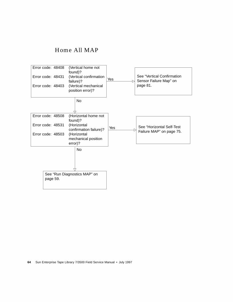
64 Sun Enterprise Tape Library 7/3500 Field Service Manual • July 1997
Home All MAP
Error code: 48408 (Vertical home notfound)?
Error code: 48431 (Vertical confirmationfailure)?
Error code: 48403 (Vertical mechanicalposition error)?
See “Vertical ConfirmationSensor Failure Map” onpage 81.
See “Horizontal Self-TestFailure MAP” on page 75.
Error code: 48508 (Horizontal home notfound)?
Error code: 48531 (Horizontalconfirmation failure)?
Error code: 48503 (Horizontalmechanical positionerror)?
See “Run Diagnostics MAP” onpage 59.
Yes
Yes
No
No
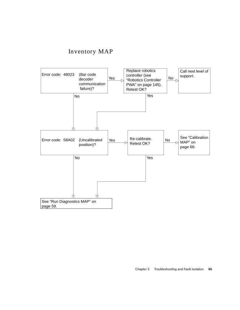
Chapter 3 Troubleshooting and Fault Isolation 65
Inventory MAP
Call next level ofsupport.
See “CalibrationMAP” onpage 66.
Error code: 48023 (Bar codedecodercommunication failure)?
Replace roboticscontroller (see“Robotics ControllerPWA” on page 145).Retest OK?
Error code: 58A02 (Uncalibratedposition)?
Re-calibrate.Retest OK?
See “Run Diagnostics MAP” onpage 59.
No
No
No
No
Yes
Yes
Yes
Yes
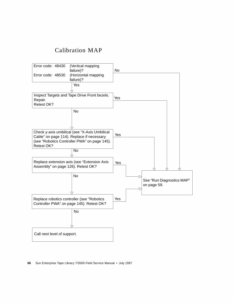
66 Sun Enterprise Tape Library 7/3500 Field Service Manual • July 1997
Calibration MAP
Check y-axis umbilical (see “X-Axis UmbilicalCable” on page 114). Replace if necessary(see “Robotics Controller PWA” on page 145).Retest OK?
Error code: 48430 (Vertical mappingfailure)?
Error code: 48530 (Horizontal mappingfailure)?
Inspect Targets and Tape Drive Front bezels.Repair.Retest OK?
Replace extension axis (see “Extension AxisAssembly” on page 126). Retest OK?
Replace robotics controller (see “RoboticsController PWA” on page 145). Retest OK?
Call next level of support.
See “Run Diagnostics MAP”on page 59.
Yes
No
Yes
Yes
Yes
Yes
No
No
No
No
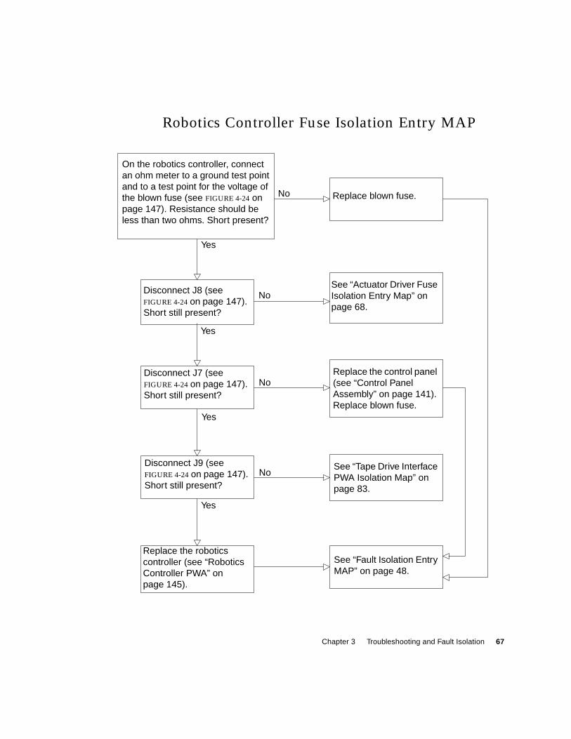
Chapter 3 Troubleshooting and Fault Isolation 67
Robotics Controller Fuse Isolation Entry MAP
Replace the roboticscontroller (see “RoboticsController PWA” onpage 145).
On the robotics controller, connectan ohm meter to a ground test pointand to a test point for the voltage ofthe blown fuse (see FIGURE 4-24 onpage 147). Resistance should beless than two ohms. Short present?
Disconnect J8 (seeFIGURE 4-24 on page 147).Short still present?
See “Actuator Driver FuseIsolation Entry Map” onpage 68.
Replace blown fuse.
Disconnect J7 (seeFIGURE 4-24 on page 147).Short still present?
Replace the control panel(see “Control PanelAssembly” on page 141).Replace blown fuse.
Disconnect J9 (seeFIGURE 4-24 on page 147).Short still present?
See “Tape Drive InterfacePWA Isolation Map” onpage 83.
See “Fault Isolation EntryMAP” on page 48.
No
No
No
No
Yes
Yes
Yes
Yes
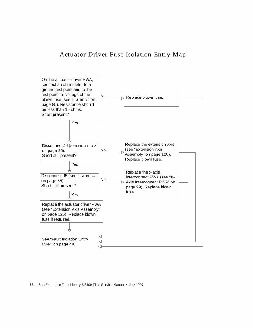
68 Sun Enterprise Tape Library 7/3500 Field Service Manual • July 1997
Actuator Driver Fuse Isolation Entry Map
Replace the extension axis(see “Extension AxisAssembly” on page 126).Replace blown fuse.
Replace the x-axisinterconnect PWA (see “X-Axis Interconnect PWA” onpage 99). Replace blownfuse.
On the actuator driver PWA,connect an ohm meter to aground test point and to thetest point for voltage of theblown fuse (see FIGURE 3-2 onpage 85). Resistance shouldbe less than 10 ohms.Short present?
Replace blown fuse.
See “Fault Isolation EntryMAP” on page 48.
Replace the actuator driver PWA(see “Extension Axis Assembly”on page 126). Replace blownfuse if required.
Disconnect J5 (see FIGURE 3-2
on page 85).Short still present?
Disconnect J4 (see FIGURE 3-2
on page 85).Short still present?
No
Yes
No
No
Yes
Yes
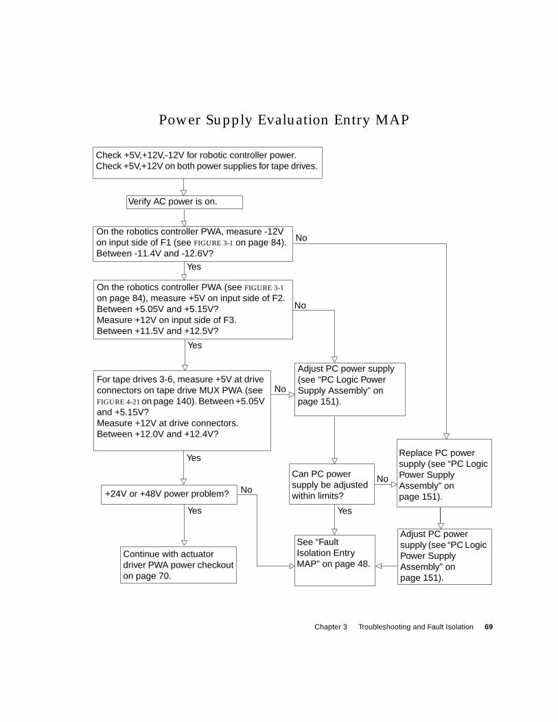
Chapter 3 Troubleshooting and Fault Isolation 69
Power Supply Evaluation Entry MAP
See “FaultIsolation EntryMAP” on page 48.
Verify AC power is on.
Check +5V,+12V,-12V for robotic controller power.Check +5V,+12V on both power supplies for tape drives.
Continue with actuatordriver PWA power checkouton page 70.
On the robotics controller PWA, measure -12Von input side of F1 (see FIGURE 3-1 on page 84).Between -11.4V and -12.6V?
On the robotics controller PWA (see FIGURE 3-1
on page 84), measure +5V on input side of F2.Between +5.05V and +5.15V?Measure +12V on input side of F3.Between +11.5V and +12.5V?
Adjust PC power supply(see “PC Logic PowerSupply Assembly” onpage 151).
+24V or +48V power problem?
Can PC powersupply be adjustedwithin limits?
Replace PC powersupply (see “PC LogicPower SupplyAssembly” onpage 151).
No
No
NoNo
Yes
Yes Yes
Adjust PC powersupply (see “PC LogicPower SupplyAssembly” onpage 151).
Yes
For tape drives 3-6, measure +5V at driveconnectors on tape drive MUX PWA (seeFIGURE 4-21 on page 140). Between +5.05Vand +5.15V?Measure +12V at drive connectors.Between +12.0V and +12.4V?
No
Yes
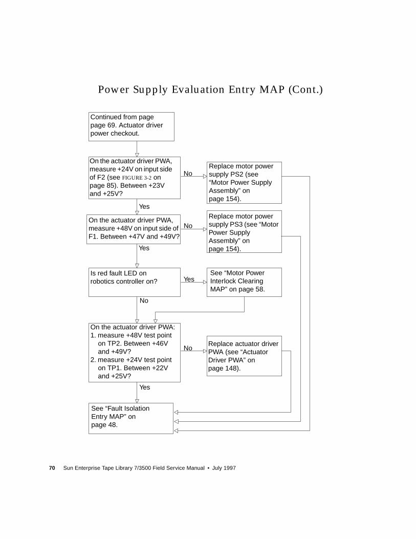
70 Sun Enterprise Tape Library 7/3500 Field Service Manual • July 1997
Power Supply Evaluation Entry MAP (Cont.)
Replace motor powersupply PS3 (see “MotorPower SupplyAssembly” onpage 154).
Replace actuator driverPWA (see “ActuatorDriver PWA” onpage 148).
On the actuator driver PWA:1. measure +48V test point
on TP2. Between +46Vand +49V?
2. measure +24V test pointon TP1. Between +22Vand +25V?
On the actuator driver PWA,measure +48V on input side ofF1. Between +47V and +49V?
On the actuator driver PWA,measure +24V on input sideof F2 (see FIGURE 3-2 onpage 85). Between +23Vand +25V?
Continued from pagepage 69. Actuator driverpower checkout.
Replace motor powersupply PS2 (see“Motor Power SupplyAssembly” onpage 154).
Is red fault LED onrobotics controller on?
See “Motor PowerInterlock ClearingMAP” on page 58.
See “Fault IsolationEntry MAP” onpage 48.
No
No
No
No
Yes
Yes
Yes
Yes
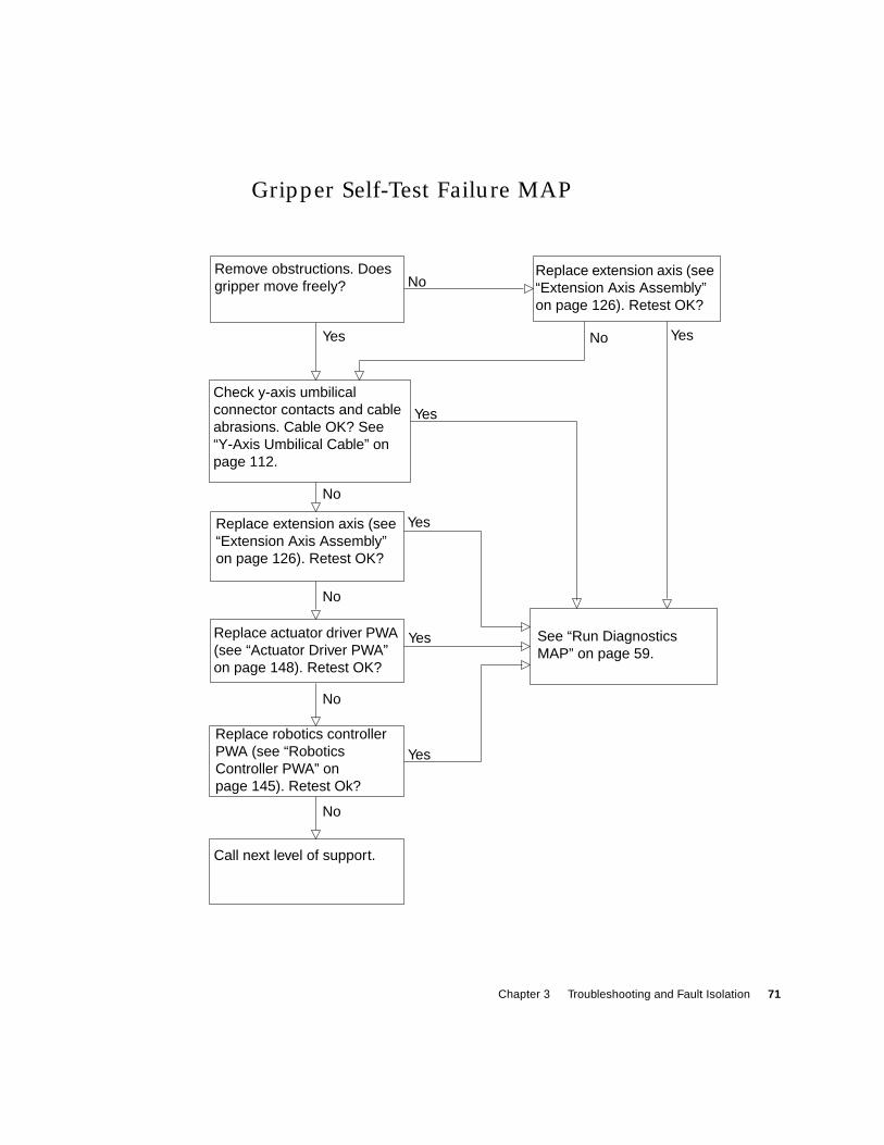
Chapter 3 Troubleshooting and Fault Isolation 71
Gripper Self-Test Failure MAP
Replace robotics controllerPWA (see “RoboticsController PWA” onpage 145). Retest Ok?
Replace actuator driver PWA(see “Actuator Driver PWA”on page 148). Retest OK?
Replace extension axis (see“Extension Axis Assembly”on page 126). Retest OK?
Remove obstructions. Doesgripper move freely?
Check y-axis umbilicalconnector contacts and cableabrasions. Cable OK? See“Y-Axis Umbilical Cable” onpage 112.
Replace extension axis (see“Extension Axis Assembly”on page 126). Retest OK?
See “Run DiagnosticsMAP” on page 59.
Call next level of support.
No
No
No
No
No
No
Yes
Yes
Yes
Yes
Yes
Yes
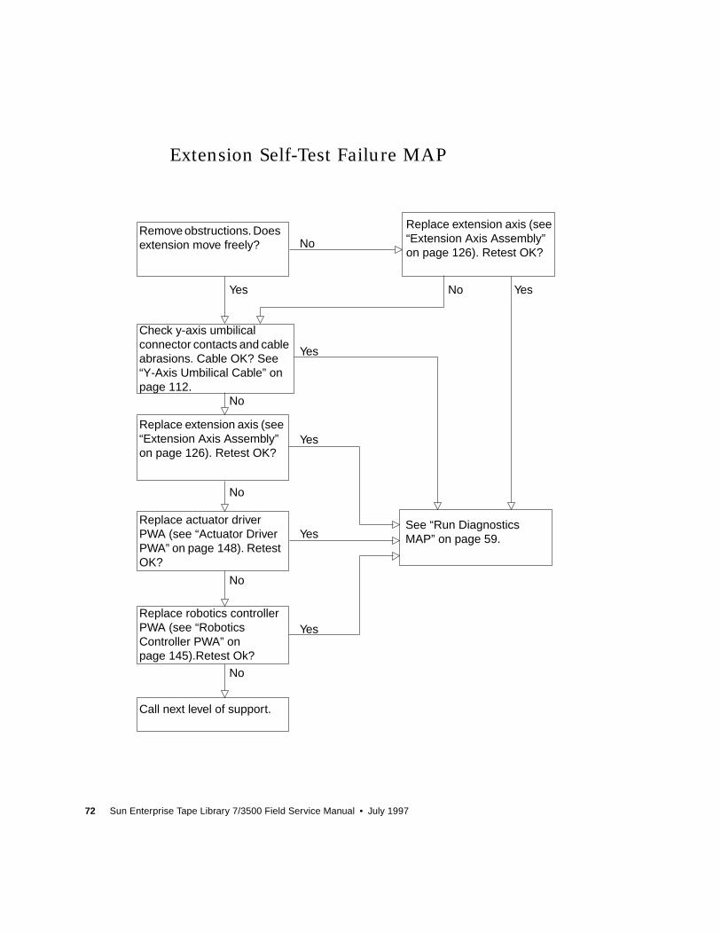
72 Sun Enterprise Tape Library 7/3500 Field Service Manual • July 1997
Extension Self-Test Failure MAP
Call next level of support.
Replace robotics controllerPWA (see “RoboticsController PWA” onpage 145).Retest Ok?
Replace actuator driverPWA (see “Actuator DriverPWA” on page 148). RetestOK?
Replace extension axis (see“Extension Axis Assembly”on page 126). Retest OK?
Remove obstructions. Doesextension move freely?
Check y-axis umbilicalconnector contacts and cableabrasions. Cable OK? See“Y-Axis Umbilical Cable” onpage 112.
Replace extension axis (see“Extension Axis Assembly”on page 126). Retest OK?
See “Run DiagnosticsMAP” on page 59.
No
No
No
No
No
No
Yes
Yes
Yes
Yes
Yes
Yes
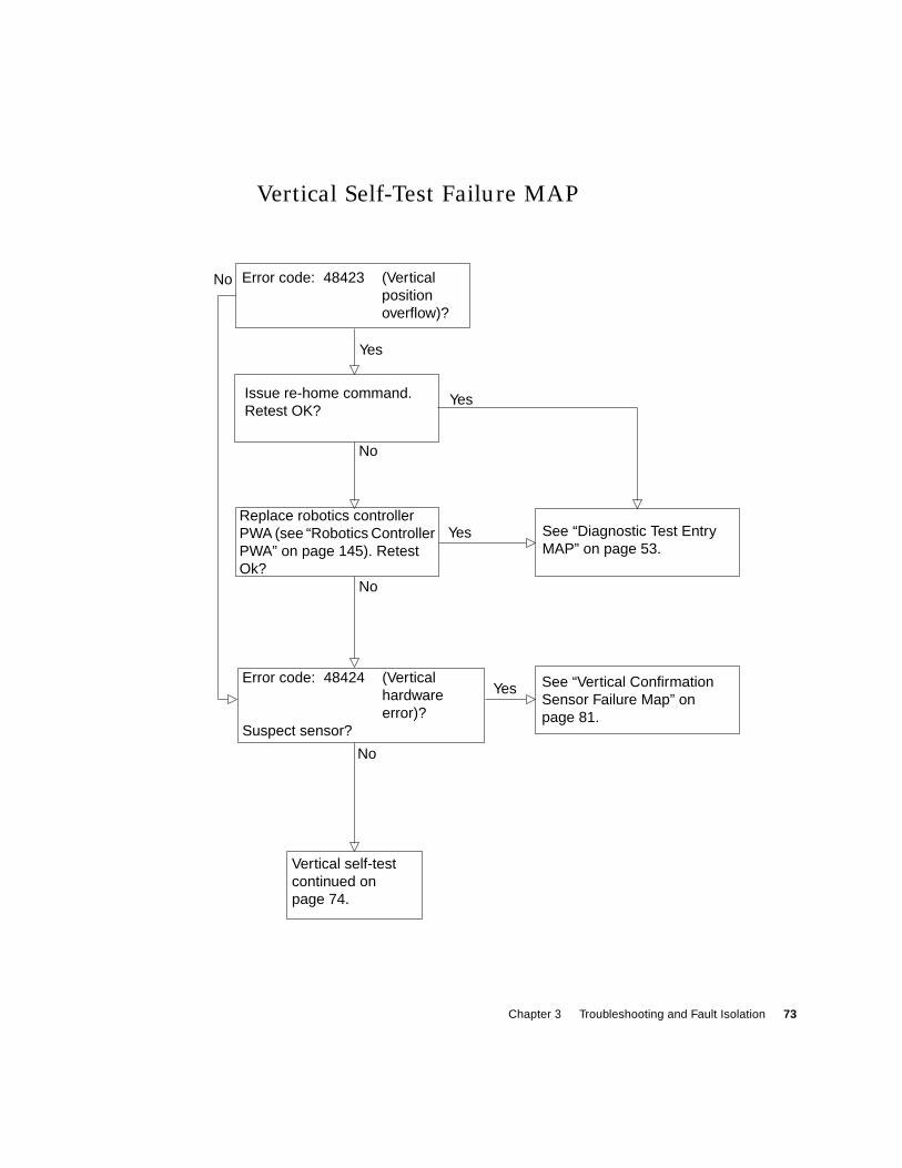
Chapter 3 Troubleshooting and Fault Isolation 73
Vertical Self-Test Failure MAP
Error code: 48423 (Verticalpositionoverflow)?
Issue re-home command.Retest OK?
See “Diagnostic Test EntryMAP” on page 53.
Error code: 48424 (Verticalhardwareerror)?
Suspect sensor?
See “Vertical ConfirmationSensor Failure Map” onpage 81.
Vertical self-testcontinued onpage 74.
No
Yes
No
No
No
Yes
Yes
Yes
Replace robotics controllerPWA (see “Robotics ControllerPWA” on page 145). RetestOk?
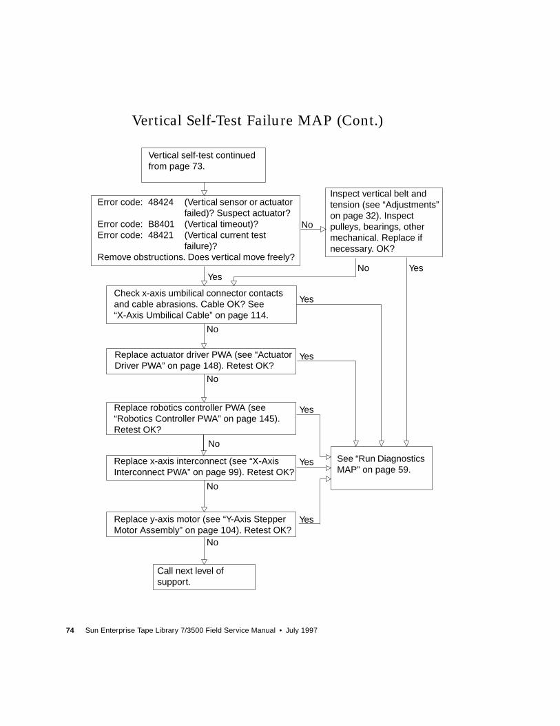
74 Sun Enterprise Tape Library 7/3500 Field Service Manual • July 1997
Vertical Self-Test Failure MAP (Cont.)
Replace x-axis interconnect (see “X-AxisInterconnect PWA” on page 99). Retest OK?
Replace actuator driver PWA (see “ActuatorDriver PWA” on page 148). Retest OK?
Inspect vertical belt andtension (see “Adjustments”on page 32). Inspectpulleys, bearings, othermechanical. Replace ifnecessary. OK?
Error code: 48424 (Vertical sensor or actuatorfailed)? Suspect actuator?
Error code: B8401 (Vertical timeout)?Error code: 48421 (Vertical current test
failure)?Remove obstructions. Does vertical move freely?
No
Yes
Check x-axis umbilical connector contactsand cable abrasions. Cable OK? See“X-Axis Umbilical Cable” on page 114.
Replace robotics controller PWA (see“Robotics Controller PWA” on page 145).Retest OK?
Replace y-axis motor (see “Y-Axis StepperMotor Assembly” on page 104). Retest OK?
See “Run DiagnosticsMAP” on page 59.
Call next level ofsupport.
Vertical self-test continuedfrom page 73.
Yes
Yes
Yes
Yes
Yes
Yes
No
No
No
No
No
No
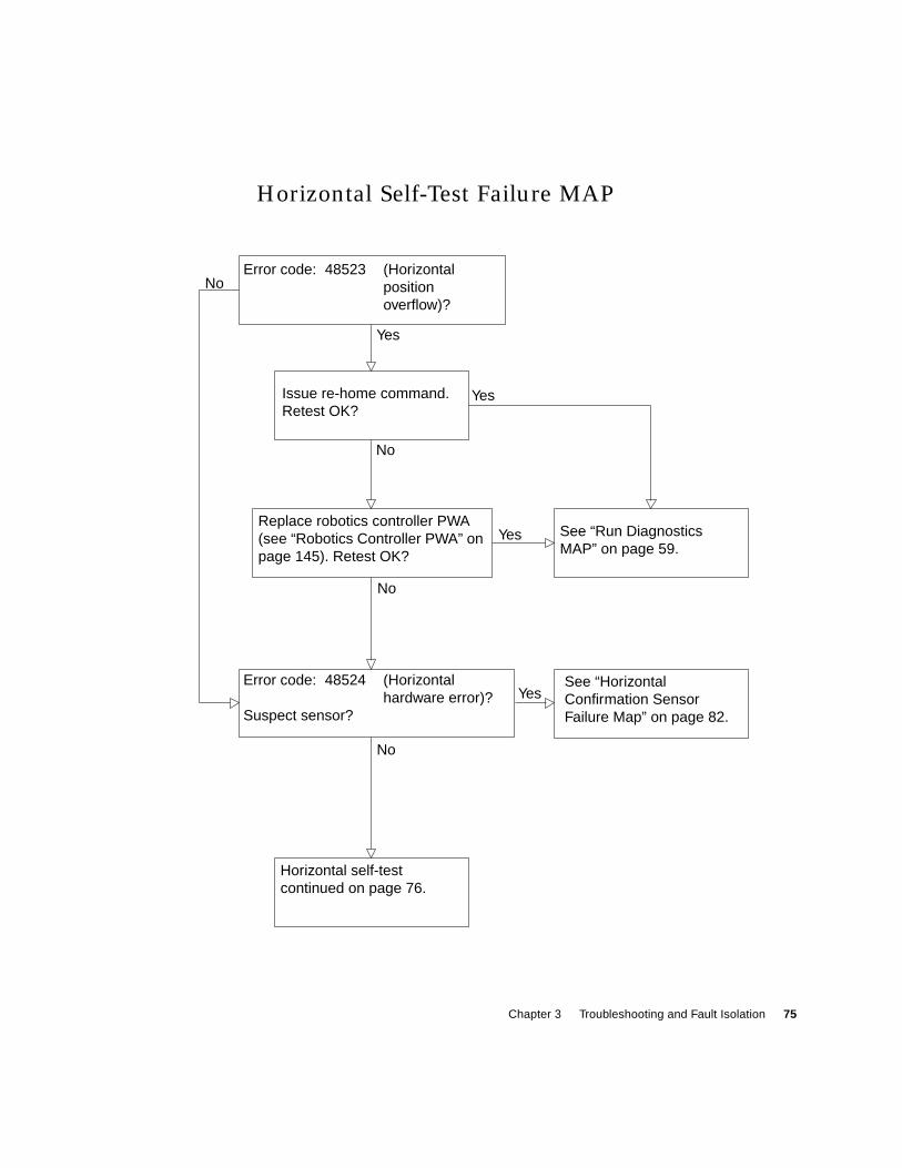
Chapter 3 Troubleshooting and Fault Isolation 75
Horizontal Self-Test Failure MAP
Error code: 48523 (Horizontalpositionoverflow)?
Issue re-home command.Retest OK?
Replace robotics controller PWA(see “Robotics Controller PWA” onpage 145). Retest OK?
See “Run DiagnosticsMAP” on page 59.
Error code: 48524 (Horizontalhardware error)?
Suspect sensor?
See “HorizontalConfirmation SensorFailure Map” on page 82.
Horizontal self-testcontinued on page 76.
Yes
Yes
Yes
Yes
No
No
No
No
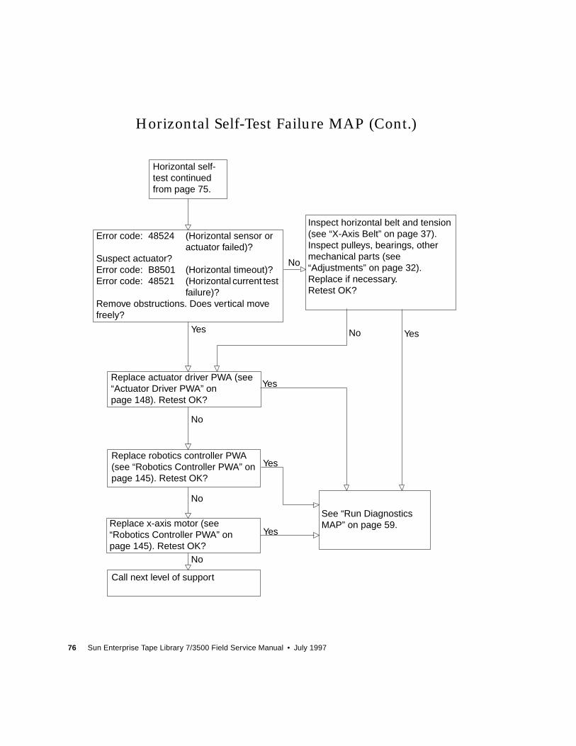
76 Sun Enterprise Tape Library 7/3500 Field Service Manual • July 1997
Horizontal Self-Test Failure MAP (Cont.)
Inspect horizontal belt and tension(see “X-Axis Belt” on page 37).Inspect pulleys, bearings, othermechanical parts (see“Adjustments” on page 32).Replace if necessary.Retest OK?
Replace x-axis motor (see“Robotics Controller PWA” onpage 145). Retest OK?
Error code: 48524 (Horizontal sensor oractuator failed)?
Suspect actuator?Error code: B8501 (Horizontal timeout)?Error code: 48521 (Horizontal current test
failure)?Remove obstructions. Does vertical movefreely?
Horizontal self-test continuedfrom page 75.
Replace actuator driver PWA (see“Actuator Driver PWA” onpage 148). Retest OK?
Replace robotics controller PWA(see “Robotics Controller PWA” onpage 145). Retest OK?
See “Run DiagnosticsMAP” on page 59.
Call next level of support
No
No
No
No
No
Yes Yes
Yes
Yes
Yes
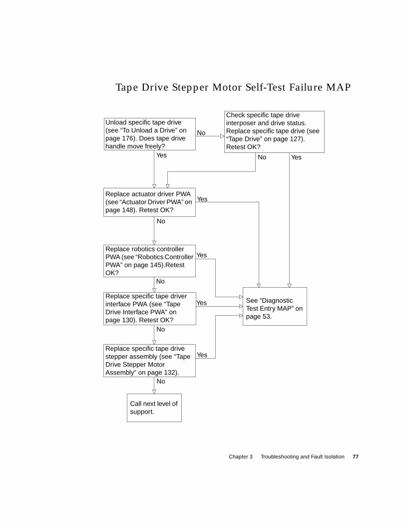
Chapter 3 Troubleshooting and Fault Isolation 77
Tape Drive Stepper Motor Self-Test Failure MAP
Replace robotics controllerPWA (see “Robotics ControllerPWA” on page 145).RetestOK?
Unload specific tape drive(see “To Unload a Drive” onpage 176). Does tape drivehandle move freely?
Check specific tape driveinterposer and drive status.Replace specific tape drive (see“Tape Drive” on page 127).Retest OK?
Replace actuator driver PWA(see “Actuator Driver PWA” onpage 148). Retest OK?
Replace specific tape driverinterface PWA (see “TapeDrive Interface PWA” onpage 130). Retest OK?
Replace specific tape drivestepper assembly (see “TapeDrive Stepper MotorAssembly” on page 132).
Call next level ofsupport.
See “DiagnosticTest Entry MAP” onpage 53.
No
No
No
No
No
No
Yes Yes
Yes
Yes
Yes
Yes
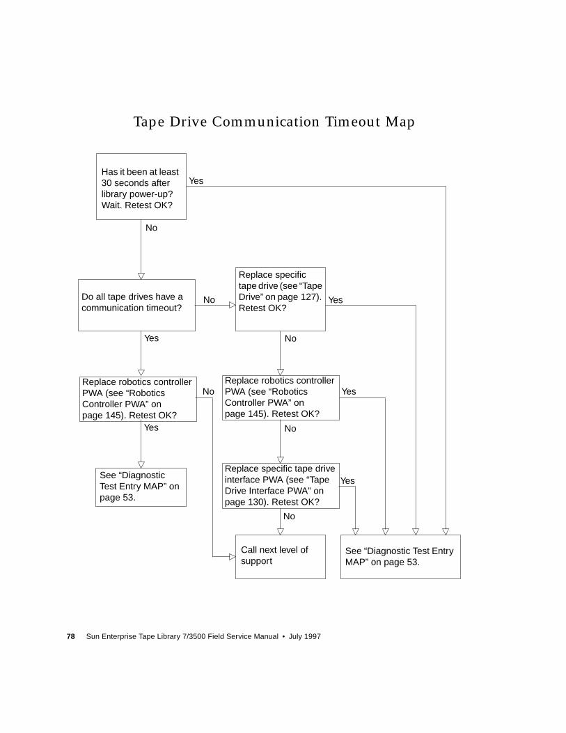
78 Sun Enterprise Tape Library 7/3500 Field Service Manual • July 1997
Tape Drive Communication Timeout Map
Replace specific tape driveinterface PWA (see “TapeDrive Interface PWA” onpage 130). Retest OK?
Replace robotics controllerPWA (see “RoboticsController PWA” onpage 145). Retest OK?
Replace robotics controllerPWA (see “RoboticsController PWA” onpage 145). Retest OK?
Has it been at least30 seconds afterlibrary power-up?Wait. Retest OK?
Do all tape drives have acommunication timeout?
Replace specifictape drive (see “TapeDrive” on page 127).Retest OK?
See “DiagnosticTest Entry MAP” onpage 53.
Call next level ofsupport
See “Diagnostic Test EntryMAP” on page 53.
No
No
No
No
No
No
Yes
Yes
Yes
Yes
Yes
Yes
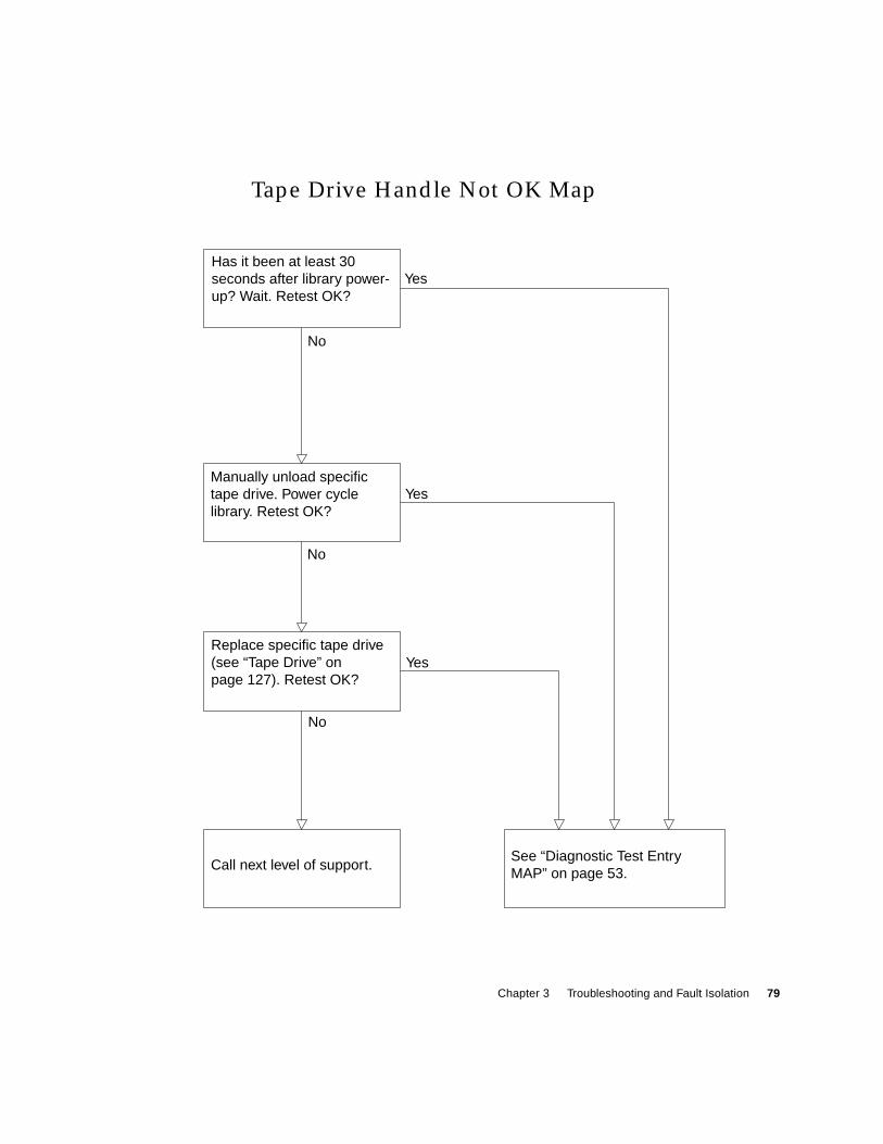
Chapter 3 Troubleshooting and Fault Isolation 79
Tape Drive Handle Not OK Map
Has it been at least 30seconds after library power-up? Wait. Retest OK?
Manually unload specifictape drive. Power cyclelibrary. Retest OK?
Replace specific tape drive(see “Tape Drive” onpage 127). Retest OK?
Call next level of support.See “Diagnostic Test EntryMAP” on page 53.
No
No
No
Yes
Yes
Yes
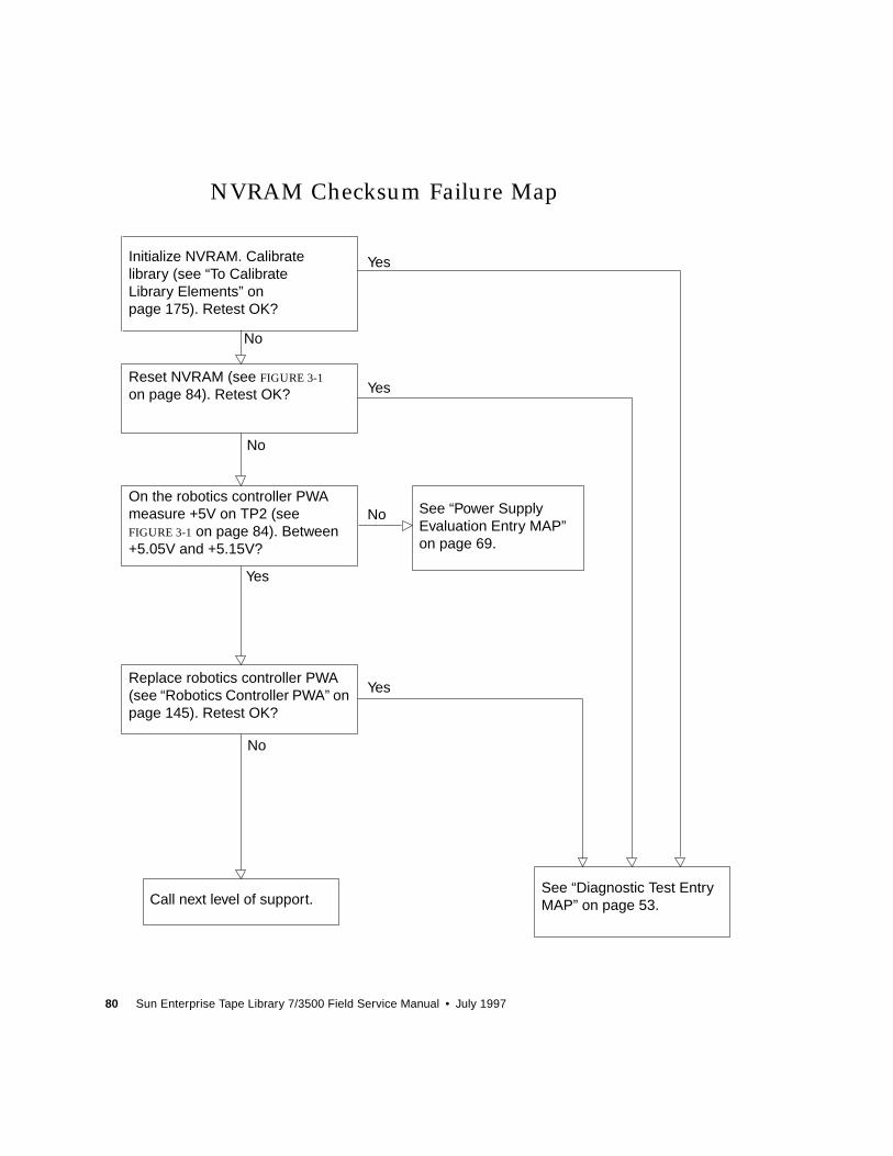
80 Sun Enterprise Tape Library 7/3500 Field Service Manual • July 1997
NVRAM Checksum Failure Map
Initialize NVRAM. Calibratelibrary (see “To CalibrateLibrary Elements” onpage 175). Retest OK?
Reset NVRAM (see FIGURE 3-1
on page 84). Retest OK?
On the robotics controller PWAmeasure +5V on TP2 (seeFIGURE 3-1 on page 84). Between+5.05V and +5.15V?
See “Power SupplyEvaluation Entry MAP”on page 69.
Replace robotics controller PWA(see “Robotics Controller PWA” onpage 145). Retest OK?
See “Diagnostic Test EntryMAP” on page 53.Call next level of support.
No
No
No
No
Yes
Yes
Yes
Yes
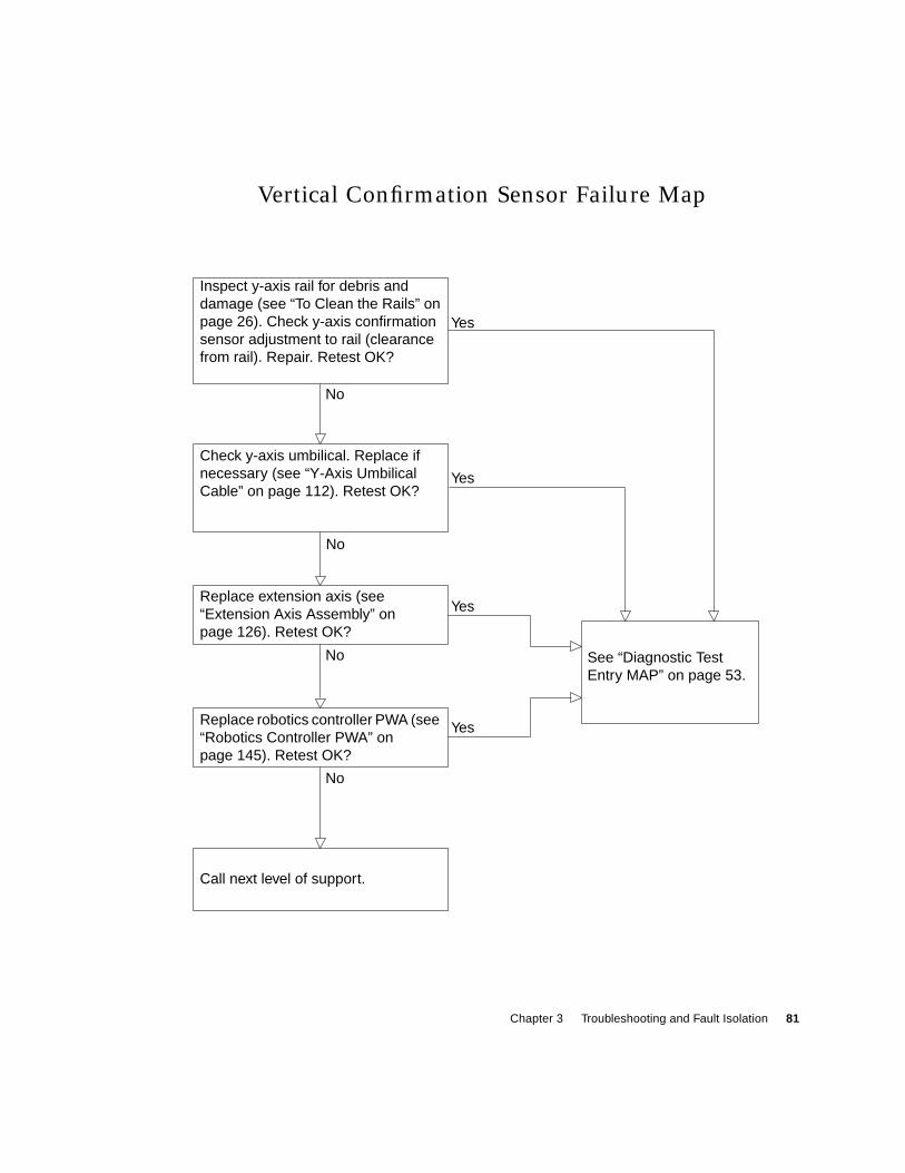
Chapter 3 Troubleshooting and Fault Isolation 81
Vertical Confirmation Sensor Failure Map
Inspect y-axis rail for debris anddamage (see “To Clean the Rails” onpage 26). Check y-axis confirmationsensor adjustment to rail (clearancefrom rail). Repair. Retest OK?
Check y-axis umbilical. Replace ifnecessary (see “Y-Axis UmbilicalCable” on page 112). Retest OK?
Replace extension axis (see“Extension Axis Assembly” onpage 126). Retest OK?
See “Diagnostic TestEntry MAP” on page 53.
Replace robotics controller PWA (see“Robotics Controller PWA” onpage 145). Retest OK?
Call next level of support.
No
Yes
Yes
Yes
Yes
No
No
No
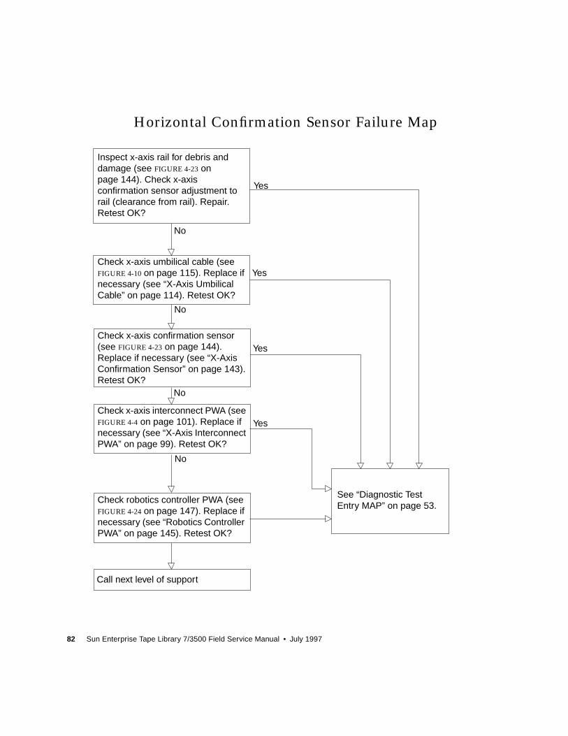
82 Sun Enterprise Tape Library 7/3500 Field Service Manual • July 1997
Horizontal Confirmation Sensor Failure Map
Check x-axis confirmation sensor(see FIGURE 4-23 on page 144).Replace if necessary (see “X-AxisConfirmation Sensor” on page 143).Retest OK?
Check x-axis interconnect PWA (seeFIGURE 4-4 on page 101). Replace ifnecessary (see “X-Axis InterconnectPWA” on page 99). Retest OK?
Inspect x-axis rail for debris anddamage (see FIGURE 4-23 onpage 144). Check x-axisconfirmation sensor adjustment torail (clearance from rail). Repair.Retest OK?
Check x-axis umbilical cable (seeFIGURE 4-10 on page 115). Replace ifnecessary (see “X-Axis UmbilicalCable” on page 114). Retest OK?
See “Diagnostic TestEntry MAP” on page 53.
Call next level of support
Yes
Yes
Yes
Yes
No
No
No
No
Check robotics controller PWA (seeFIGURE 4-24 on page 147). Replace ifnecessary (see “Robotics ControllerPWA” on page 145). Retest OK?
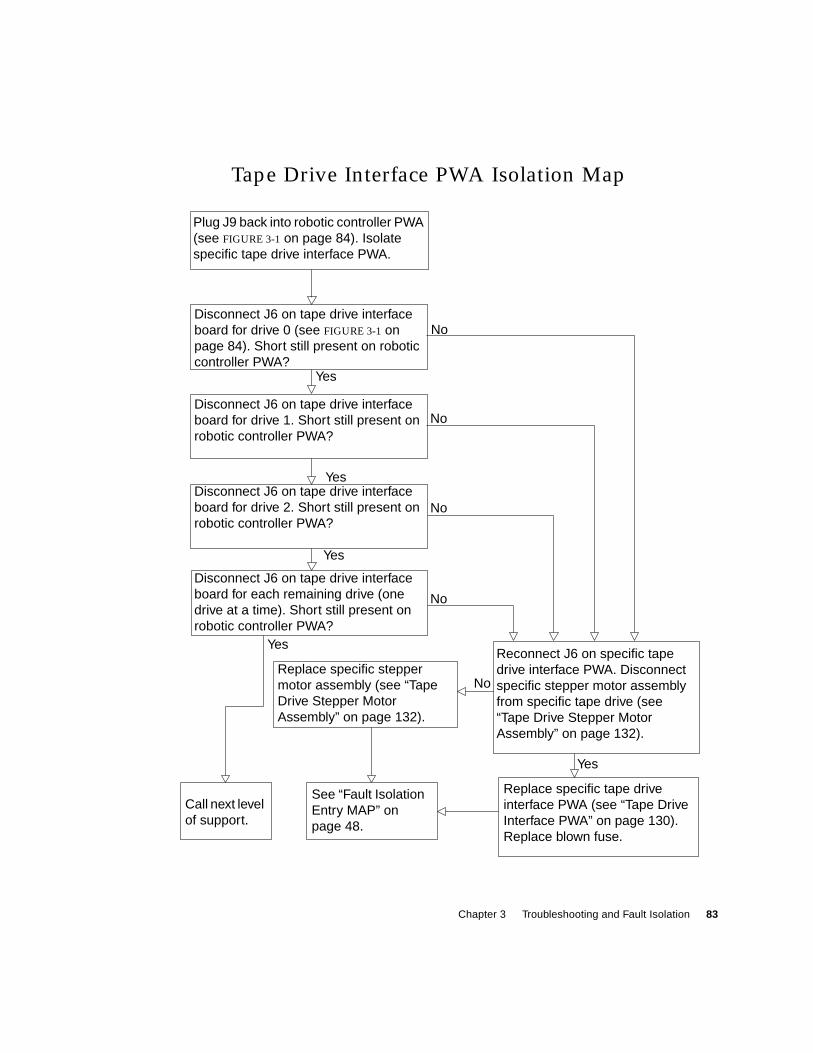
Chapter 3 Troubleshooting and Fault Isolation 83
Tape Drive Interface PWA Isolation Map
Replace specific tape driveinterface PWA (see “Tape DriveInterface PWA” on page 130).Replace blown fuse.
Replace specific steppermotor assembly (see “TapeDrive Stepper MotorAssembly” on page 132).
Disconnect J6 on tape drive interfaceboard for drive 2. Short still present onrobotic controller PWA?
Disconnect J6 on tape drive interfaceboard for drive 0 (see FIGURE 3-1 onpage 84). Short still present on roboticcontroller PWA?
Plug J9 back into robotic controller PWA(see FIGURE 3-1 on page 84). Isolatespecific tape drive interface PWA.
Reconnect J6 on specific tapedrive interface PWA. Disconnectspecific stepper motor assemblyfrom specific tape drive (see“Tape Drive Stepper MotorAssembly” on page 132).
Call next levelof support.
See “Fault IsolationEntry MAP” onpage 48.
No
Yes
No
Yes
No
Yes
No
Yes
No
Yes
Disconnect J6 on tape drive interfaceboard for drive 1. Short still present onrobotic controller PWA?
Disconnect J6 on tape drive interfaceboard for each remaining drive (onedrive at a time). Short still present onrobotic controller PWA?
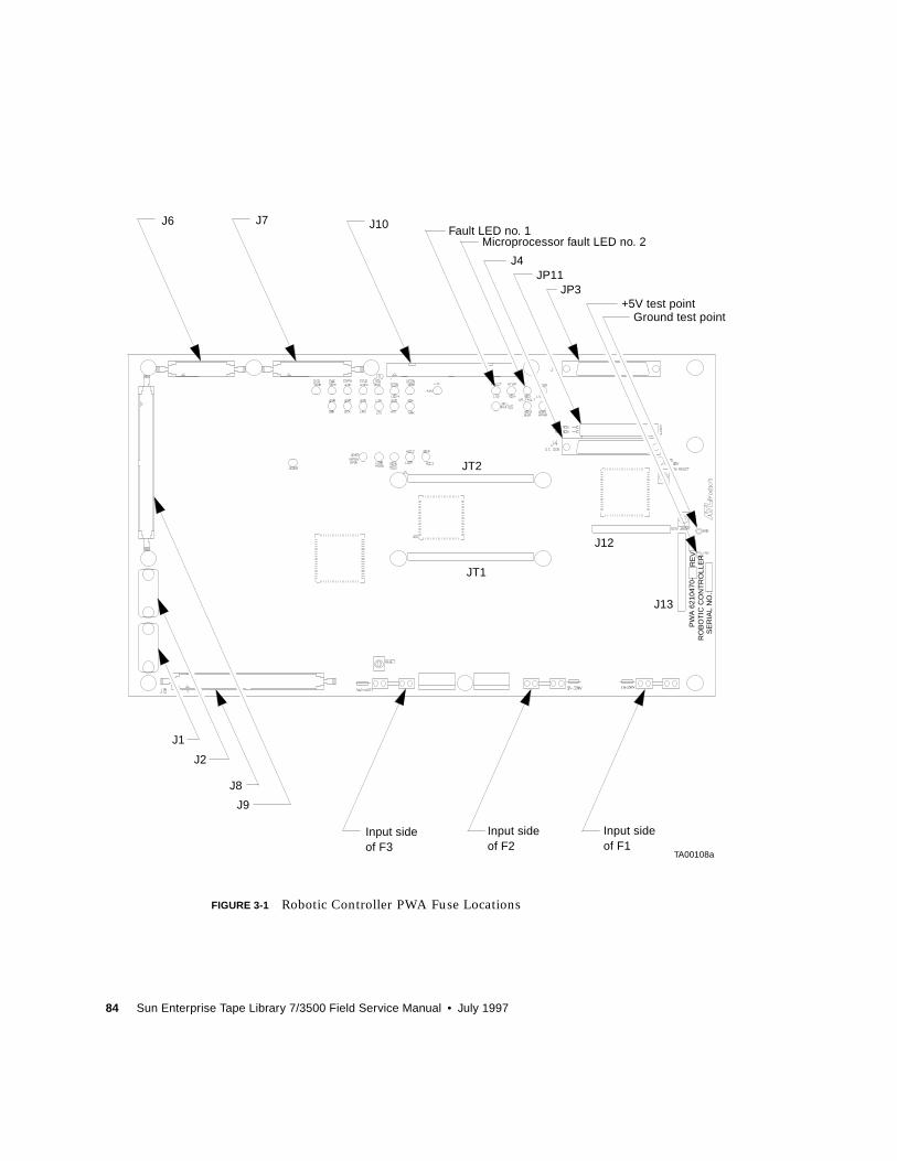
84 Sun Enterprise Tape Library 7/3500 Field Service Manual • July 1997
FIGURE 3-1 Robotic Controller PWA Fuse Locations
TA00108a
1A-250VP
WA
621
0470
-R
OB
OT
IC C
ON
TR
OLL
ER
RE
V
SE
RIA
L N
O.:
J6 J7 J10
J4JP11
JP3
J13
J1
J2
J9
Input sideInput sideInput side
JT2
JT1
J8
Ground test point+5V test point
J12
Microprocessor fault LED no. 2Fault LED no. 1
of F2of F3 of F1
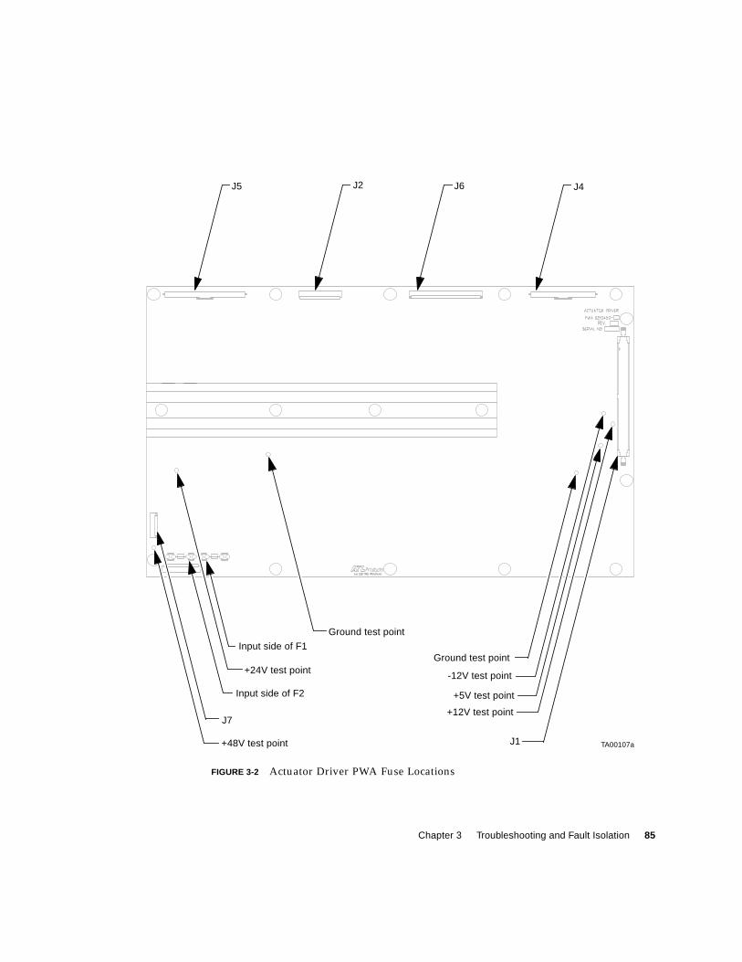
Chapter 3 Troubleshooting and Fault Isolation 85
FIGURE 3-2 Actuator Driver PWA Fuse Locations
TA00107a
Input side of F2
Input side of F1
+24V test point
J7
+48V test point
Ground test point
Ground test point
-12V test point
+5V test point
+12V test point
J1
J5 J2 J6 J4
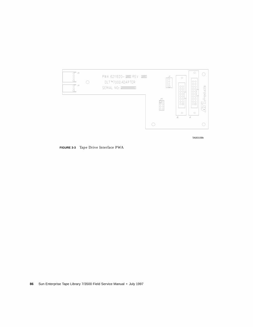
86 Sun Enterprise Tape Library 7/3500 Field Service Manual • July 1997
FIGURE 3-3 Tape Drive Interface PWA
TA00109b
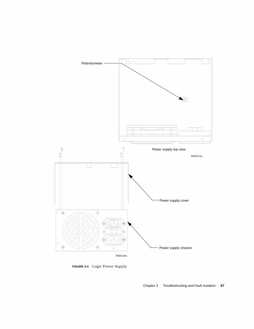
Chapter 3 Troubleshooting and Fault Isolation 87
FIGURE 3-4 Logic Power Supply
TA00110a
TA00111a
Power supply cover
Power supply chassis
Power supply top view
Potentiometer

88 Sun Enterprise Tape Library 7/3500 Field Service Manual • July 1997
89
CHAPTER 4
FRU Removal and Replacement
This chapter contains a list of all field replaceable units (FRUs) of the ETL 7/3500
Library and the procedures for removing and replacing them.
Preparing for Maintenance
The procedures in this section are written for the FRUs listed in TABLE 4-1 on page 98
and under the assumption that the library has been prepared for maintenance. The
preparation of the library includes removing power from the library and removing
the appropriate cosmetic panels. To prepare the library for maintenance, use the
procedures that follow.
▼ To Turn Off the Library
Caution – Employ all appropriate measures to protect the library from electrostatic
discharge (ESD) damage.
1. Press control panel STANDBY switch and verify that System Offline is displayedin the status display area (SDA).
2. At the rear panel, set the power switch to the 0 (off) position.
Caution – DO NOT disconnect the power cord from facility power or the library.
The power cord is the only means of grounding the chassis and helping to prevent
electrostatic discharge (ESD) damage.

90 Sun Enterprise Tape Library 7/3500 Field Service Manual • July 1997
▼ To Take the Library Offline
1. With the library power applied and the SDA showing System Online, press thecontrol panel STANDBY button.
2. Verify that System Offline is displayed in the SDA.
Removing the Cosmetic Panels
Use the procedures below along with FIGURE 4-1 and FIGURE 4-2 to remove the
cosmetic panels.
Caution – Employ all appropriate measures to protect the library from ESD
damage.
▼ To Remove the Top Panel
1. Remove power from the library.
Caution – DO NOT disconnect the power cord from facility power or the library.
The power cord is the only means of grounding the chassis and helping to prevent
electrostatic discharge (ESD) damage.
2. At the rear of the library, remove the screws that secure the top panel to the rear ofthe library frame (FIGURE 4-1).
3. Pull the top panel towards the rear of the library (to disengage the retention tabsfrom the frame top) and then up and off of the library frame.
4. Set aside the panel.
▼ To Remove the Left Panel
Caution – You must remove the top panel before removing the left panel.
1. Remove power from the library.
Caution – DO NOT disconnect the power cord from facility power or the library.
The power cord is the only means of grounding the chassis and helping to prevent
electrostatic discharge (ESD) damage.

Chapter 4 FRU Removal and Replacement 91
2. At the rear of the library, remove the screws that secure the left panel to the rear ofthe library frame (FIGURE 4-1).
3. Pull the left-rear panel towards the rear of the library (to disengage the retentiontabs attached to the left of the frame) and then away from the library frame.
4. Set aside the panel.
92 Sun Enterprise Tape Library 7/3500 Field Service Manual • July 1997
FIGURE 4-1 Top, Right, and Left Panels
Top panel
Right
Left
TJ00020A
panel
panel
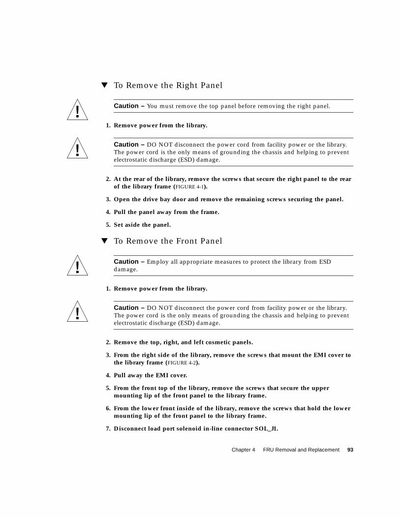
Chapter 4 FRU Removal and Replacement 93
▼ To Remove the Right Panel
Caution – You must remove the top panel before removing the right panel.
1. Remove power from the library.
Caution – DO NOT disconnect the power cord from facility power or the library.
The power cord is the only means of grounding the chassis and helping to prevent
electrostatic discharge (ESD) damage.
2. At the rear of the library, remove the screws that secure the right panel to the rearof the library frame (FIGURE 4-1).
3. Open the drive bay door and remove the remaining screws securing the panel.
4. Pull the panel away from the frame.
5. Set aside the panel.
▼ To Remove the Front Panel
Caution – Employ all appropriate measures to protect the library from ESD
damage.
1. Remove power from the library.
Caution – DO NOT disconnect the power cord from facility power or the library.
The power cord is the only means of grounding the chassis and helping to prevent
electrostatic discharge (ESD) damage.
2. Remove the top, right, and left cosmetic panels.
3. From the right side of the library, remove the screws that mount the EMI cover tothe library frame (FIGURE 4-2).
4. Pull away the EMI cover.
5. From the front top of the library, remove the screws that secure the uppermounting lip of the front panel to the library frame.
6. From the lower front inside of the library, remove the screws that hold the lowermounting lip of the front panel to the library frame.
7. Disconnect load port solenoid in-line connector SOL_J1.
94 Sun Enterprise Tape Library 7/3500 Field Service Manual • July 1997
8. Carefully slide the front panel (from the top) away from the library frame.
9. Disconnect the front door interlock switch in-line connector SW2_J1.
10. Disconnect blade connectors from the load port switches SW1 and SW2.
Note – Take care not to stress any cables connected between the front panel and the
frame.
11. Disconnect control panel ribbon connector A3_J1.
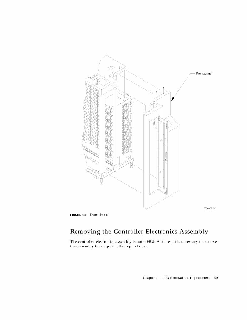
Chapter 4 FRU Removal and Replacement 95
FIGURE 4-2 Front Panel
Removing the Controller Electronics Assembly
The controller electronics assembly is not a FRU. At times, it is necessary to remove
this assembly to complete other operations.
TJ00072a
Front panel
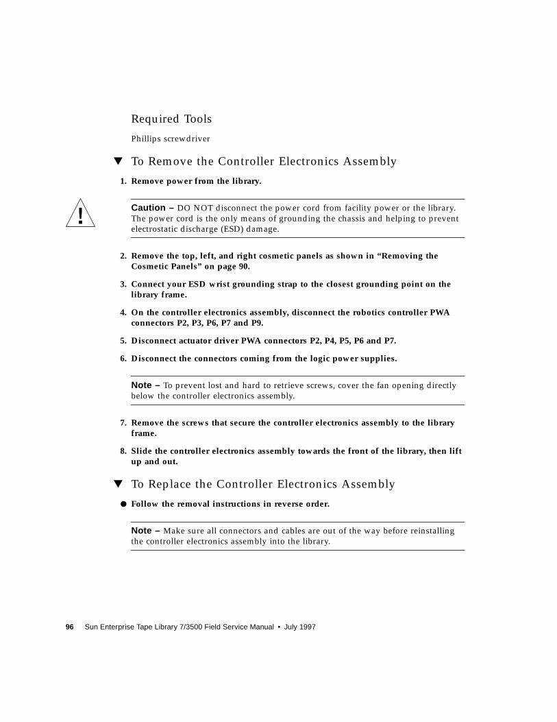
96 Sun Enterprise Tape Library 7/3500 Field Service Manual • July 1997
Required Tools
Phillips screwdriver
▼ To Remove the Controller Electronics Assembly
1. Remove power from the library.
Caution – DO NOT disconnect the power cord from facility power or the library.
The power cord is the only means of grounding the chassis and helping to prevent
electrostatic discharge (ESD) damage.
2. Remove the top, left, and right cosmetic panels as shown in “Removing theCosmetic Panels” on page 90.
3. Connect your ESD wrist grounding strap to the closest grounding point on thelibrary frame.
4. On the controller electronics assembly, disconnect the robotics controller PWAconnectors P2, P3, P6, P7 and P9.
5. Disconnect actuator driver PWA connectors P2, P4, P5, P6 and P7.
6. Disconnect the connectors coming from the logic power supplies.
Note – To prevent lost and hard to retrieve screws, cover the fan opening directly
below the controller electronics assembly.
7. Remove the screws that secure the controller electronics assembly to the libraryframe.
8. Slide the controller electronics assembly towards the front of the library, then liftup and out.
▼ To Replace the Controller Electronics Assembly
● Follow the removal instructions in reverse order.
Note – Make sure all connectors and cables are out of the way before reinstalling
the controller electronics assembly into the library.
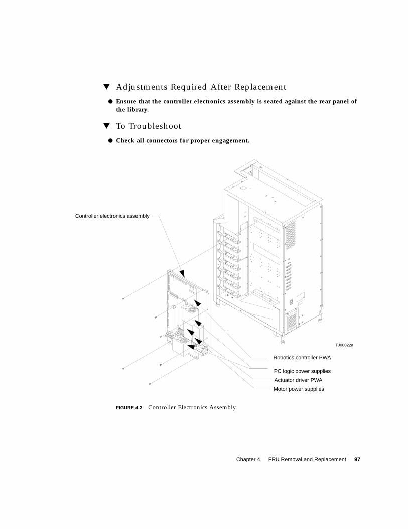
Chapter 4 FRU Removal and Replacement 97
▼ Adjustments Required After Replacement
● Ensure that the controller electronics assembly is seated against the rear panel ofthe library.
▼ To Troubleshoot
● Check all connectors for proper engagement.
FIGURE 4-3 Controller Electronics Assembly
Controller electronics assembly
Robotics controller PWA
PC logic power supplies
Actuator driver PWA
Motor power supplies
TJ00022a
98 Sun Enterprise Tape Library 7/3500 Field Service Manual • July 1997
FRU Removal and ReplacementProcedures
Caution – Perform all replacement procedures with the library power removed.
Failure to remove power could result in injury or damage to the equipment.
TABLE 4-1 is a list of all FRUs of the library. The removal/replacement procedures are
written for authorized field service engineers (FSEs) only.
Caution – Do not attempt field repair of FRUs. The FRUs specified in this section
are replaceable in the field, but must be repaired at the factory.
Caution – Employ all appropriate measures to protect the library from ESD
damage.
TABLE 4-1 FRU List
Part Number FRU Name Page
6210480-01 X-Axis Interconnect PWA 99
6210510-01 Y-Axis Stepper Motor Assembly 104
6210511-01 X-Axis Stepper Motor Assembly 102
6210512-01 Load Port Door Lockout Solenoid 107
6210516-01 Front Door Interlock Switch 110
6210518-01 Y-Axis Umbilical Cable 112
6210520-02 X-Axis Umbilical Cable 114
0645115 X-Axis Drive Belt 116
0645116 Y-Axis Drive Belt 118
6240515-01 DC Fan Assembly 121
6240516-01 DC Fan Assembly 121
6240720-01 Extension Axis Assembly 126
6210202-06 Tape Drive 127
Chapter 4 FRU Removal and Replacement 99
X-Axis Interconnect PWA
Required Tools
Phillips screwdriver, flashlight
▼ To Remove the X-Axis Interconnect PWA
1. Remove power from the library.
Caution – DO NOT disconnect the power cord from facility power or the library.
The power cord is the only means of grounding the chassis and helping to prevent
electrostatic discharge (ESD) damage.
2. Remove the top, left, and right side cosmetic panels as shown in “Top, Right, andLeft Panels” on page 92.
3. Connect your ESD wrist grounding strap to the closest grounding point on thelibrary frame.
4. Move the horizontal axis to the front of the library positioning the gripperdirectly under the tape drives.
6211630-01 Tape Drive Interface PWA 130
0815033 Tape Drive Stepper Motor Assembly 132
6204202-01 Tape Drive Tray Assembly 134
6240320-01 Tape Drive Distribution PWA 136
6240330-01 Tape Drive MUX PWA 138
6210440-01 Control Panel Assembly 141
6210515-03 X-Axis Confirmation Sensor 143
6210470-01 Robotics Controller PWA 145
6210450-01 Actuator Driver PWA 148
0355038 Motor Power Supply Assembly 154
0355041 PC Logic Power Supply Assembly 151
TABLE 4-1 FRU List (Continued)
Part Number FRU Name Page
100 Sun Enterprise Tape Library 7/3500 Field Service Manual • July 1997
Note – The PWA is accessed through the service port directly under the tape drives.
5. From the right side, remove the Phillips screws securing the strain relief to thePWA.
6. Disconnect the cables.
7. From the left side, remove the ESD guard mounting hardware.
8. From the right side, remove the guard and liner.
Caution – Pay attention to the orientation of connector Px when you remove it.
Reinstalling connector A4_J4 incorrectly causes the library robotics to malfunction
and may cause damage to the library.
9. Disconnect the horizontal home sensor, connector A4_J4.
10. Disconnect the y-axis motor connector A4_K3.
11. Remove the remaining two Phillips screws that secure the PWA to the horizontalframe.
12. Carefully lift the PWA out of the library.
▼ To Replace the X-Axis Interconnect PWA
● Follow the removal instructions in reverse order.
▼ To Troubleshoot
● If the library malfunctions, check the orientation of the horizontal home sensorconnector A4_J4 and reseat it if necessary.
Chapter 4 FRU Removal and Replacement 101
FIGURE 4-4 X-Axis Interconnect PWA
TJ00075a
A4_J3
A4_J1
A4_J4
A4_J3
11
1
1
A4_J4

102 Sun Enterprise Tape Library 7/3500 Field Service Manual • July 1997
X-Axis Stepper Motor Assembly
Required Tools
Phillips screwdriver, 5/32 allen wrench
▼ To Remove the X-Axis Stepper Motor Assembly
1. Remove power from the library.
Caution – DO NOT disconnect the power cord from facility power or the library.
The power cord is the only means of grounding the chassis and helping to prevent
electrostatic discharge (ESD) damage.
2. Remove the top, left, and right cosmetic panels as shown in “Top, Right, and LeftPanels” on page 92.
3. Connect your ESD wrist grounding strap to the closest grounding point on thelibrary frame.
4. Position the horizontal axis toward the front of the library.
5. From the left rear of the library, locate the x-axis stepper motor assembly. See(FIGURE 4-5).
6. Disconnect the x-axis stepper motor in-line connector J1 that is plugged intoconnector M2_J2.
7. Cut the cable ties that secure the x-axis stepper motor cable.
8. Loosen the horizontal belt at the horizontal belt tensioner. See “X-Axis Belt” onpage 40.
9. Remove the four screws that secure the x-axis stepper motor mounting bracket tothe frame.
10. Remove the four screws that secure the x-axis stepper motor to its mountingbracket.
▼ To Replace the X-Axis Stepper Motor Assembly
● Follow the removal instructions in reverse order.
Chapter 4 FRU Removal and Replacement 103
▼ To Make Adjustments Required After Replacement
1. Complete horizontal belt tension adjustment using “X-Axis Belt” on page 40.
2. Auto calibrate all.
A loose horizontal belt produces an unusual amount of noise when the horizontal
axis moves.
FIGURE 4-5 X-Axis Stepper Motor Assembly
TJ00037a
Horizontal belt
Mounting bracket
Frame
Stepper motor
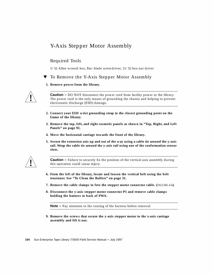
104 Sun Enterprise Tape Library 7/3500 Field Service Manual • July 1997
Y-Axis Stepper Motor Assembly
Required Tools
5/32 Allen wrench hex, flat- blade screwdriver, 11/32 hex nut driver
▼ To Remove the Y-Axis Stepper Motor Assembly
1. Remove power from the library.
Caution – DO NOT disconnect the power cord from facility power or the library.
The power cord is the only means of grounding the chassis and helping to prevent
electrostatic discharge (ESD) damage.
2. Connect your ESD wrist grounding strap to the closest grounding point on theframe of the library.
3. Remove the top, left, and right cosmetic panels as shown in “Top, Right, and LeftPanels” on page 92.
4. Move the horizontal carriage towards the front of the library.
5. Secure the extension axis up and out of the way using a cable tie around the y-axisrail. Wrap the cable tie around the y-axis rail using one of the conformation sensorslots.
Caution – Failure to securely fix the position of the vertical axis assembly during
this operation could cause injury.
6. From the left of the library, locate and loosen the vertical belt using the belttensioner. See “To Clean the Rollers” on page 31.
7. Remove the cable clamps to free the stepper motor connector cable. (FIGURE 4-6).
8. Disconnect the y-axis stepper motor connector P1 and remove cable clampsholding the harness to back of PWA.
Note – Pay attention to the routing of the harness before removal.
9. Remove the screws that secure the y-axis stepper motor to the x-axis carriageassembly and lift it out.
Chapter 4 FRU Removal and Replacement 105
▼ To Replace the Y-Axis Stepper Motor Assembly
● Follow the removal instructions in reverse order.
▼ To Make Adjustments Required After Replacement
1. Adjust vertical belt tension. See “Y-Axis Belt” on page 37.
2. Adjust horizontal belt tension. See “X-Axis Belt” on page 40.
3. Auto calibrate all.
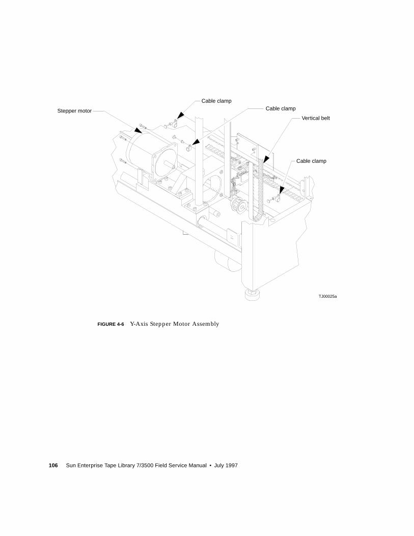
106 Sun Enterprise Tape Library 7/3500 Field Service Manual • July 1997
FIGURE 4-6 Y-Axis Stepper Motor Assembly
Stepper motor
Cable clampCable clamp
Vertical belt
Cable clamp
TJ00025a
Chapter 4 FRU Removal and Replacement 107
4
Load Port Door Lockout Solenoid
Required Tools
Phillips screwdriver, crescent wrench, small punch
▼ To Remove the Load Port Door Lockout Solenoid
1. Remove power from the library.
Caution – DO NOT disconnect the power cord from facility power or the library.
The power cord is the only means of grounding the chassis and helping to prevent
electrostatic discharge (ESD) damage.
2. Connect your ESD wrist grounding strap to the closest grounding point on theframe of the library.
3. Remove the top, left, and right cosmetic panels as shown in “Top, Right, and LeftPanels” on page 92.
4. Remove the front cover as shown in “Top, Right, and Left Panels” on page 92.
5. With the front panel removed, locate the load port door lockout solenoid frominside the front panel. (FIGURE 4-7).
6. Disconnect the in-line solenoid connector J1 plugged into SOL_J1.
7. Remove the self-locking nuts that secure the load port upper pivot block to thefront panel.
8. Remove the pivot block from the front panel.
9. Invert the pivot block and lift out the load port locking lever assembly.
10. Remove the solenoid from the solenoid mounting bracket by removing thesolenoid retaining nut and lock washer.
108 Sun Enterprise Tape Library 7/3500 Field Service Manual • July 1997
Note – Take note of the wire and connector orientation exiting the solenoid before
disassembling.
11. With the solenoid plunger on a firm surface, press out the pivot pin.
▼ To Replace the Load Port Door Lockout Solenoid
● Follow the removal instructions in reverse order.
Note – Special attention should be paid to the coil orientation of the pin when
reinstalling.
▼ To Make Adjustments Required After Replacement
● Auto calibrate load port.
Chapter 4 FRU Removal and Replacement 109
FIGURE 4-7 Load Port Door Lockout Solenoid
Pivot block
Solenoid plunger
Solenoid
Front panel
TJ00073a
Pivot pin
110 Sun Enterprise Tape Library 7/3500 Field Service Manual • July 1997
Front Door Interlock Switch
Required Tools
Snap ring pliers with angled tip, diagonal cutters
▼ To Remove the Front Door Interlock Switch
1. Remove power from the library.
Caution – DO NOT disconnect the power cord from facility power or the library.
The power cord is the only means of grounding the chassis and helping to prevent
electrostatic discharge (ESD) damage.
2. Connect your ESD wrist grounding strap to the closest grounding point on theframe of the library.
3. Remove the top, left, and right cosmetic panels as shown in “Top, Right, and LeftPanels” on page 92.
4. Open the front door.
5. From the left lower side of the library, locate and disconnect the front doorinterlock switch connector J1, which is plugged into SW2_J1 connector. See(FIGURE 4-8).
6. Using snap ring pliers, remove the snap ring that holds the interlock switch.
7. Lift the interlock switch and its cable up through hole.
▼ Replacing the Front Door Interlock Switch
● Follow the removal instructions in reverse order.
Chapter 4 FRU Removal and Replacement 111
FIGURE 4-8 Front Door Interlock Switch
Interlock switch
Snap ring
Front cosmetic panel
Front door
TJ00074a
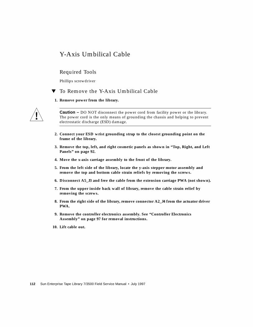
112 Sun Enterprise Tape Library 7/3500 Field Service Manual • July 1997
Y-Axis Umbilical Cable
Required Tools
Phillips screwdriver
▼ To Remove the Y-Axis Umbilical Cable
1. Remove power from the library.
Caution – DO NOT disconnect the power cord from facility power or the library.
The power cord is the only means of grounding the chassis and helping to prevent
electrostatic discharge (ESD) damage.
2. Connect your ESD wrist grounding strap to the closest grounding point on theframe of the library.
3. Remove the top, left, and right cosmetic panels as shown in “Top, Right, and LeftPanels” on page 92.
4. Move the x-axis carriage assembly to the front of the library.
5. From the left side of the library, locate the y-axis stepper motor assembly andremove the top and bottom cable strain reliefs by removing the screws.
6. Disconnect A5_J3 and free the cable from the extension carriage PWA (not shown).
7. From the upper inside back wall of library, remove the cable strain relief byremoving the screws.
8. From the right side of the library, remove connector A2_J4 from the actuator driverPWA.
9. Remove the controller electronics assembly. See “Controller ElectronicsAssembly” on page 97 for removal instructions.
10. Lift cable out.
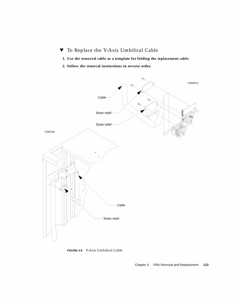
Chapter 4 FRU Removal and Replacement 113
▼ To Replace the Y-Axis Umbilical Cable
1. Use the removed cable as a template for folding the replacement cable.
2. Follow the removal instructions in reverse order.
FIGURE 4-9 Y-Axis Umbilical Cable
Strain relief
Cable
Cable
Strain relief
Strain relief
TJ00076a
TA00087a
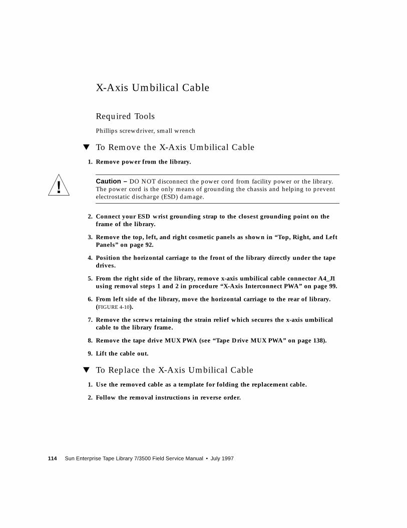
114 Sun Enterprise Tape Library 7/3500 Field Service Manual • July 1997
X-Axis Umbilical Cable
Required Tools
Phillips screwdriver, small wrench
▼ To Remove the X-Axis Umbilical Cable
1. Remove power from the library.
Caution – DO NOT disconnect the power cord from facility power or the library.
The power cord is the only means of grounding the chassis and helping to prevent
electrostatic discharge (ESD) damage.
2. Connect your ESD wrist grounding strap to the closest grounding point on theframe of the library.
3. Remove the top, left, and right cosmetic panels as shown in “Top, Right, and LeftPanels” on page 92.
4. Position the horizontal carriage to the front of the library directly under the tapedrives.
5. From the right side of the library, remove x-axis umbilical cable connector A4_J1using removal steps 1 and 2 in procedure “X-Axis Interconnect PWA” on page 99.
6. From left side of the library, move the horizontal carriage to the rear of library.(FIGURE 4-10).
7. Remove the screws retaining the strain relief which secures the x-axis umbilicalcable to the library frame.
8. Remove the tape drive MUX PWA (see “Tape Drive MUX PWA” on page 138).
9. Lift the cable out.
▼ To Replace the X-Axis Umbilical Cable
1. Use the removed cable as a template for folding the replacement cable.
2. Follow the removal instructions in reverse order.
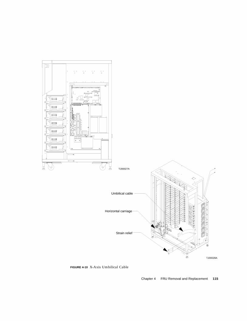
Chapter 4 FRU Removal and Replacement 115
FIGURE 4-10 X-Axis Umbilical Cable
Horizontal carriage
Strain relief
Umbilical cable
TJ00028A
TJ00027A
OP
EN
AC
T
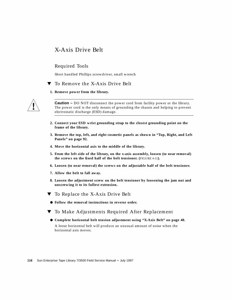
116 Sun Enterprise Tape Library 7/3500 Field Service Manual • July 1997
X-Axis Drive Belt
Required Tools
Short handled Phillips screwdriver, small wrench
▼ To Remove the X-Axis Drive Belt
1. Remove power from the library.
Caution – DO NOT disconnect the power cord from facility power or the library.
The power cord is the only means of grounding the chassis and helping to prevent
electrostatic discharge (ESD) damage.
2. Connect your ESD wrist grounding strap to the closest grounding point on theframe of the library.
3. Remove the top, left, and right cosmetic panels as shown in “Top, Right, and LeftPanels” on page 92.
4. Move the horizontal axis to the middle of the library.
5. From the left side of the library, on the x-axis assembly, loosen (to near removal)the screws on the fixed half of the belt tensioner. (FIGURE 4-11).
6. Loosen (to near removal) the screws on the adjustable half of the belt tensioner.
7. Allow the belt to fall away.
8. Loosen the adjustment screw on the belt tensioner by loosening the jam nut andunscrewing it to its fullest extension.
▼ To Replace the X-Axis Drive Belt
● Follow the removal instructions in reverse order.
▼ To Make Adjustments Required After Replacement
● Complete horizontal belt tension adjustment using “X-Axis Belt” on page 40.
A loose horizontal belt will produce an unusual amount of noise when the
horizontal axis moves.
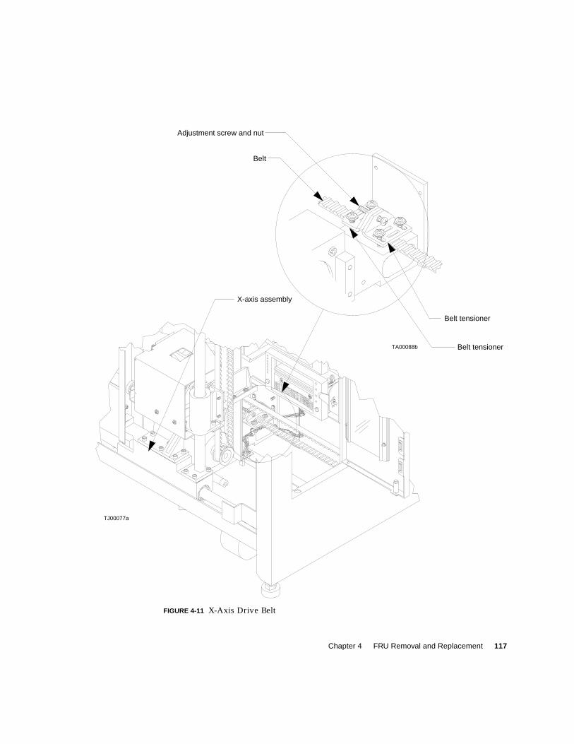
Chapter 4 FRU Removal and Replacement 117
FIGURE 4-11 X-Axis Drive Belt
TA00088b
Belt
Adjustment screw and nut
Belt tensioner
Belt tensioner
X-axis assembly
TJ00077a
118 Sun Enterprise Tape Library 7/3500 Field Service Manual • July 1997
Y-Axis Drive Belt
Required Tools
Short handled Phillips screwdriver, small wrench
▼ To Remove the Y-Axis Drive Belt
1. Remove power from the library.
Caution – DO NOT disconnect the power cord from facility power or the library.
The power cord is the only means of grounding the chassis and helping to prevent
electrostatic discharge (ESD) damage.
2. Connect your ESD wrist grounding strap to the closest grounding point on theframe of the library.
3. Remove the top, left, and right cosmetic panels as shown in “Top, Right, and LeftPanels” on page 92.
4. Move the horizontal axis to the rear of the library and secure the extension axisassembly midway up the y-axis.
5. From the left side of the library, on the y-axis assembly, loosen the belt tensioningadjustment screw by loosening the jam nut and unscrewing it to its fullestextension. (FIGURE 4-12).
6. Loosen (to near removal) the screws in both halves of belt tensioner.
7. Allow the belt to fall away.
Note – The top pulley is held in place by the belt and gravity. Use care when
removing the belt not to dislodge the top pulley.
▼ To Replace the Y-Axis Drive Belt
1. Thread the belt over the top pulley (tooth side in).
2. Thread the inner side of the belt under the bottom pulley and place the last twoteeth into the tooth slots of the tensioner fixed half.
3. Hold the tensioner fixed half and belt tightly while securing the two lower screws.
4. Working with the outer side of the belt, place the last two teeth into the tooth slotsin the tensioner adjustable half.
Chapter 4 FRU Removal and Replacement 119
5. Hold the tensioner adjustable half and belt tightly while reinstalling the twoupper screws.
Note – The y-axis drive belt may need trimming.
▼ To Make Adjustments Required After Replacement
● Complete the vertical belt tension adjustments using “Y-Axis Belt” on page 37.
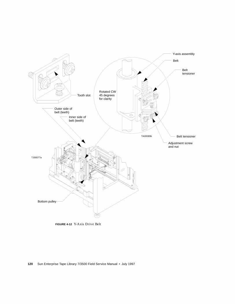
120 Sun Enterprise Tape Library 7/3500 Field Service Manual • July 1997
FIGURE 4-12 Y-Axis Drive Belt
TA00089b
Rotated CW45 degreesfor clarity
Y-axis assembly
Adjustment screw
Belt
Belt
Bottom pulley
Tooth slot
Inner side ofbelt (teeth)
Outer side ofbelt (teeth)
Belt tensioner
tensioner
and nut
TJ00077a
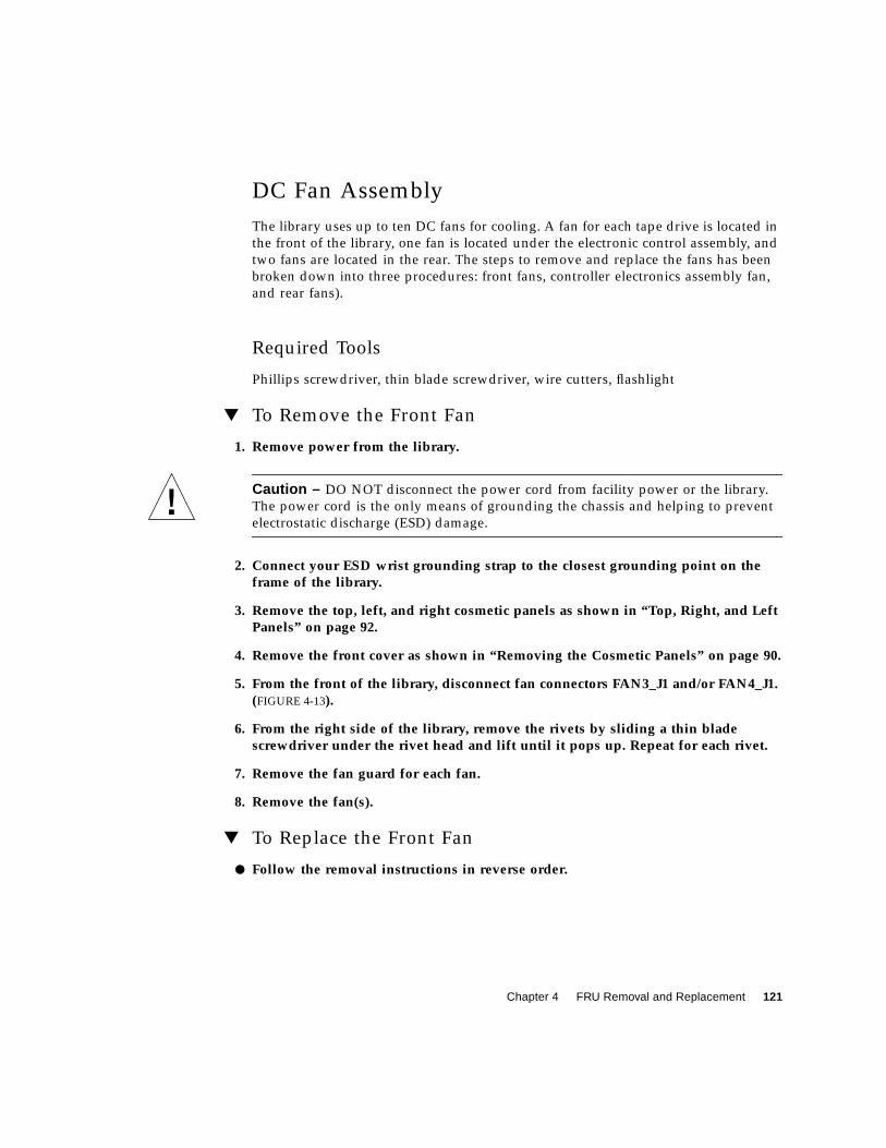
Chapter 4 FRU Removal and Replacement 121
DC Fan Assembly
The library uses up to ten DC fans for cooling. A fan for each tape drive is located in
the front of the library, one fan is located under the electronic control assembly, and
two fans are located in the rear. The steps to remove and replace the fans has been
broken down into three procedures: front fans, controller electronics assembly fan,
and rear fans).
Required Tools
Phillips screwdriver, thin blade screwdriver, wire cutters, flashlight
▼ To Remove the Front Fan
1. Remove power from the library.
Caution – DO NOT disconnect the power cord from facility power or the library.
The power cord is the only means of grounding the chassis and helping to prevent
electrostatic discharge (ESD) damage.
2. Connect your ESD wrist grounding strap to the closest grounding point on theframe of the library.
3. Remove the top, left, and right cosmetic panels as shown in “Top, Right, and LeftPanels” on page 92.
4. Remove the front cover as shown in “Removing the Cosmetic Panels” on page 90.
5. From the front of the library, disconnect fan connectors FAN3_J1 and/or FAN4_J1.(FIGURE 4-13).
6. From the right side of the library, remove the rivets by sliding a thin bladescrewdriver under the rivet head and lift until it pops up. Repeat for each rivet.
7. Remove the fan guard for each fan.
8. Remove the fan(s).
▼ To Replace the Front Fan
● Follow the removal instructions in reverse order.
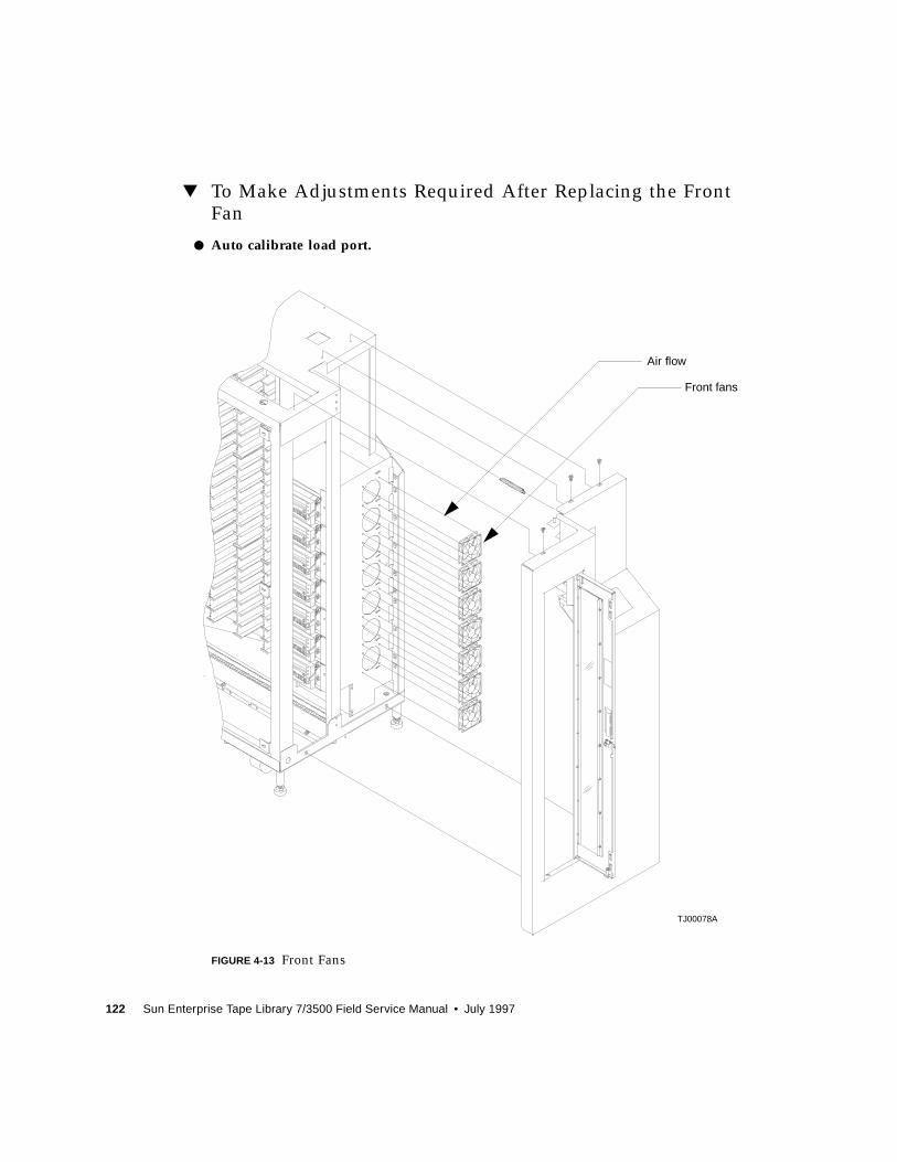
122 Sun Enterprise Tape Library 7/3500 Field Service Manual • July 1997
▼ To Make Adjustments Required After Replacing the FrontFan
● Auto calibrate load port.
FIGURE 4-13 Front Fans
TJ00078A
Front fans
Air flow

Chapter 4 FRU Removal and Replacement 123
▼ To Remove the Controller Electronics Assembly Fan
1. Free the ribbon cable from the cable clamp on the library frame.
2. Remove the standoffs that retain the connectors to the rear panel.
3. Disconnect the fan connector.
4. Slide a thin blade screwdriver under the rivet head and lift until it pops up.Repeat for each rivet.
5. Remove the finger guard.
▼ To Replace the Controller Electronics Assembly Fan
● Follow the removal instructions in reverse order.
124 Sun Enterprise Tape Library 7/3500 Field Service Manual • July 1997
▼ To Remove the Rear Fan
1. Remove the back panel.
1. Free the ribbon cable from the cable clamp on the library frame.
2. Remove the standoffs that secure the connectors to the rear panel.
3. Disconnect the fan connectors.
4. Slide a thin blade screwdriver under the rivet head and lift until it pops up.Repeat for each rivet.
5. Remove the fan guard for each fan.
▼ Replacing the Rear Fan
● Follow the removal instructions in reverse order.
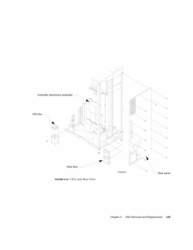
Chapter 4 FRU Removal and Replacement 125
4
FIGURE 4-14 CEA and Rear Fans
Rear panel
CEA fan
Rear fans
Controller electronics assembly
TJ00031A
126 Sun Enterprise Tape Library 7/3500 Field Service Manual • July 1997
Extension Axis Assembly
Required Tools
Phillips screwdriver, 5/32 Allen wrench
▼ To Remove the Extension Axis Assembly
1. Remove power from the library.
Caution – DO NOT disconnect the power cord from facility power or the library.
The power cord is the only means of grounding the chassis and helping to prevent
electrostatic discharge (ESD) damage.
2. Connect your ESD wrist grounding strap to the closest grounding point on theframe of the library.
3. Remove the top, left, and right cosmetic panels as shown in “Top, Right, and LeftPanels” on page 92.
4. Remove the ESD guard.
5. From the left side of the library, locate the y-axis stepper motor assembly andremove the top and bottom cable strain reliefs by removing the screws.(FIGURE 4-15).
6. Disconnect A5_J3 and free the cable from the extension carriage PWA (not shown).
7. Remove the three mounting screws that secure the extension axis to the linearbearing on the vertical rail.
Note – Hold the extension axis assembly securely when removing the last mounting
screw.
8. Gently turn the extension axis assembly clockwise and remove from between railstowards you.
▼ To Replace the Extension Axis Assembly
● Follow the removal instructions in reverse order.
▼ To Make Adjustments Required After Replacement
● Auto calibrate all.
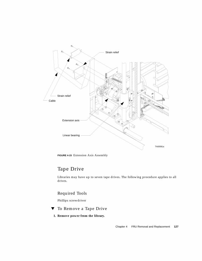
Chapter 4 FRU Removal and Replacement 127
FIGURE 4-15 Extension Axis Assembly
Tape Drive
Libraries may have up to seven tape drives. The following procedure applies to all
drives.
Required Tools
Phillips screwdriver
▼ To Remove a Tape Drive
1. Remove power from the library.
TA00081a
Cable
Extension axis
Linear bearing
Strain relief
Strain relief
128 Sun Enterprise Tape Library 7/3500 Field Service Manual • July 1997
Caution – DO NOT disconnect the power cord from facility power or the library.
The power cord is the only means of grounding the chassis and helping to prevent
electrostatic discharge (ESD) damage.
2. Connect your ESD wrist grounding strap to the closest grounding point on theframe of the library.
3. Open the drive access door.
4. Remove the tape drive tray assembly from the library. See “Tape Drive InterfacePWA” on page 131 for removal instructions.
5. Remove the screws that secure the tape drive to the mounting plate.
6. Disconnect the 3- and 4-pin connectors coming from the stepper motor assemblyto the tape drive interface PWA.
7. Remove the screws that secure the tape drive interface PWA to the PWA mountingbracket.
8. From the left side of the tape drive, remove the screws that secure the tape driveinterface PWA mounting bracket
9. Remove the bracket.
10. Remove the stepper motor assembly from the drive. See “Tape Drive StepperMotor Assembly” on page 133 for removal instructions.
▼ To Replace a Tape Drive
● Follow the removal instructions in reverse order.
▼ To Make Adjustments Required After Replacement
● Auto calibrate drives.
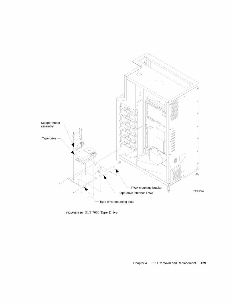
Chapter 4 FRU Removal and Replacement 129
FIGURE 4-16 DLT 7000 Tape Drive
Tape drive interface PWA
PWA mounting bracket
Stepper motor
TJ00032A
Tape drive mounting plate
Tape drive
assembly
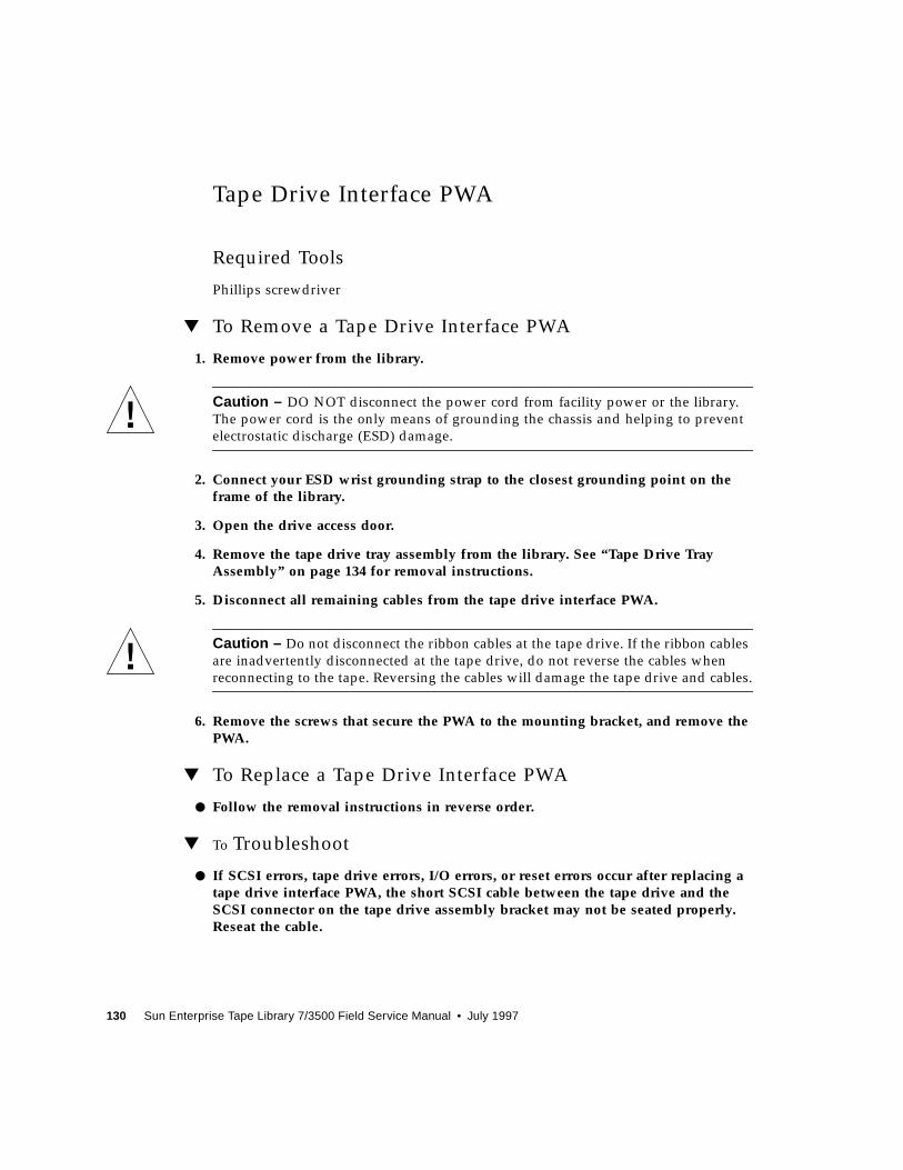
130 Sun Enterprise Tape Library 7/3500 Field Service Manual • July 1997
Tape Drive Interface PWA
Required Tools
Phillips screwdriver
▼ To Remove a Tape Drive Interface PWA
1. Remove power from the library.
Caution – DO NOT disconnect the power cord from facility power or the library.
The power cord is the only means of grounding the chassis and helping to prevent
electrostatic discharge (ESD) damage.
2. Connect your ESD wrist grounding strap to the closest grounding point on theframe of the library.
3. Open the drive access door.
4. Remove the tape drive tray assembly from the library. See “Tape Drive TrayAssembly” on page 134 for removal instructions.
5. Disconnect all remaining cables from the tape drive interface PWA.
Caution – Do not disconnect the ribbon cables at the tape drive. If the ribbon cables
are inadvertently disconnected at the tape drive, do not reverse the cables when
reconnecting to the tape. Reversing the cables will damage the tape drive and cables.
6. Remove the screws that secure the PWA to the mounting bracket, and remove thePWA.
▼ To Replace a Tape Drive Interface PWA
● Follow the removal instructions in reverse order.
▼ To Troubleshoot
● If SCSI errors, tape drive errors, I/O errors, or reset errors occur after replacing atape drive interface PWA, the short SCSI cable between the tape drive and theSCSI connector on the tape drive assembly bracket may not be seated properly.Reseat the cable.
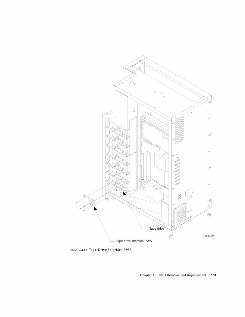
Chapter 4 FRU Removal and Replacement 131
FIGURE 4-17 Tape Drive Interface PWA
Tape drive interface PWA
Tape drive
TJ00079A

132 Sun Enterprise Tape Library 7/3500 Field Service Manual • July 1997
Tape Drive Stepper Motor Assembly
Required Tools
Phillips screwdriver
▼ To Remove a Tape Drive Stepper Motor Assembly
1. Remove power from the library.
Caution – DO NOT disconnect the power cord from facility power or the library.
The power cord is the only means of grounding the chassis and helping to prevent
electrostatic discharge (ESD) damage.
2. Connect your ESD wrist grounding strap to the closest grounding point on theframe of the library.
3. Open the drive access door.
Note – See “Tape Drive Stepper Motor Assembly” on page 133 throughout this
procedure.
▼ To Remove a Tape Drive Stepper Motor Assembly
4. Remove the tape drive tray assembly from the library. See “Tape Drive TrayAssembly” on page 135 for removal instructions.
5. Remove the fan shield from the tape drive tray assembly.
6. Disconnect the tape drive stepper motor cables from the tape drive interface PWA.
7. Loosen the captive screws that attach the stepper motor assembly to the tapedrive.
8. Lift counter clock wise and pull the stepper motor assembly off tape drive.
▼ To Replace a Tape Drive Stepper Motor Assembly
● Follow the removal instructions in reverse order.
▼ To Make Adjustments Required After Replacement
● Auto calibrate drives.
Chapter 4 FRU Removal and Replacement 133
FIGURE 4-18 Tape Drive Stepper Motor Assembly
Stepper motor
Tape drive mounting shelf
Tape drive interface PWATJ00034A
assembly
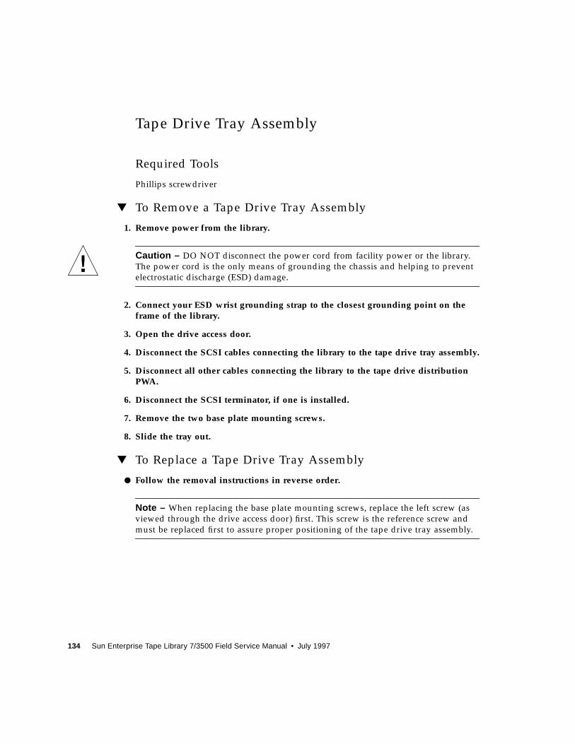
134 Sun Enterprise Tape Library 7/3500 Field Service Manual • July 1997
Tape Drive Tray Assembly
Required Tools
Phillips screwdriver
▼ To Remove a Tape Drive Tray Assembly
1. Remove power from the library.
Caution – DO NOT disconnect the power cord from facility power or the library.
The power cord is the only means of grounding the chassis and helping to prevent
electrostatic discharge (ESD) damage.
2. Connect your ESD wrist grounding strap to the closest grounding point on theframe of the library.
3. Open the drive access door.
4. Disconnect the SCSI cables connecting the library to the tape drive tray assembly.
5. Disconnect all other cables connecting the library to the tape drive distributionPWA.
6. Disconnect the SCSI terminator, if one is installed.
7. Remove the two base plate mounting screws.
8. Slide the tray out.
▼ To Replace a Tape Drive Tray Assembly
● Follow the removal instructions in reverse order.
Note – When replacing the base plate mounting screws, replace the left screw (as
viewed through the drive access door) first. This screw is the reference screw and
must be replaced first to assure proper positioning of the tape drive tray assembly.
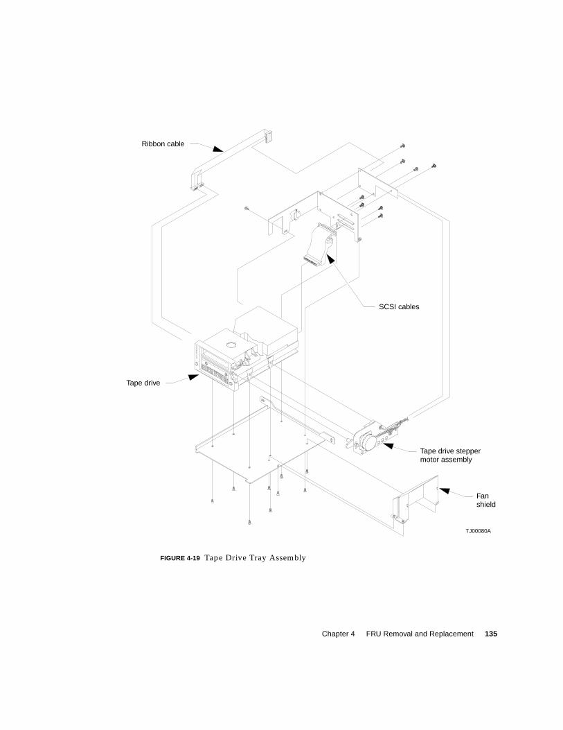
Chapter 4 FRU Removal and Replacement 135
FIGURE 4-19 Tape Drive Tray Assembly
TJ00080A
Ribbon cable
Tape drive
Tape drive steppermotor assembly
Fanshield
SCSI cables
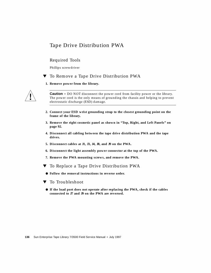
136 Sun Enterprise Tape Library 7/3500 Field Service Manual • July 1997
Tape Drive Distribution PWA
Required Tools
Phillips screwdriver
▼ To Remove a Tape Drive Distribution PWA
1. Remove power from the library.
Caution – DO NOT disconnect the power cord from facility power or the library.
The power cord is the only means of grounding the chassis and helping to prevent
electrostatic discharge (ESD) damage.
2. Connect your ESD wrist grounding strap to the closest grounding point on theframe of the library.
3. Remove the right cosmetic panel as shown in “Top, Right, and Left Panels” onpage 92.
4. Disconnect all cabling between the tape drive distribution PWA and the tapedrives.
5. Disconnect cables at J1, J3, J4, J8, and J9 on the PWA.
6. Disconnect the light assembly power connector at the top of the PWA.
7. Remove the PWA mounting screws, and remove the PWA.
▼ To Replace a Tape Drive Distribution PWA
● Follow the removal instructions in reverse order.
▼ To Troubleshoot
● If the load port does not operate after replacing the PWA, check if the cablesconnected to J7 and J9 on the PWA are reversed.
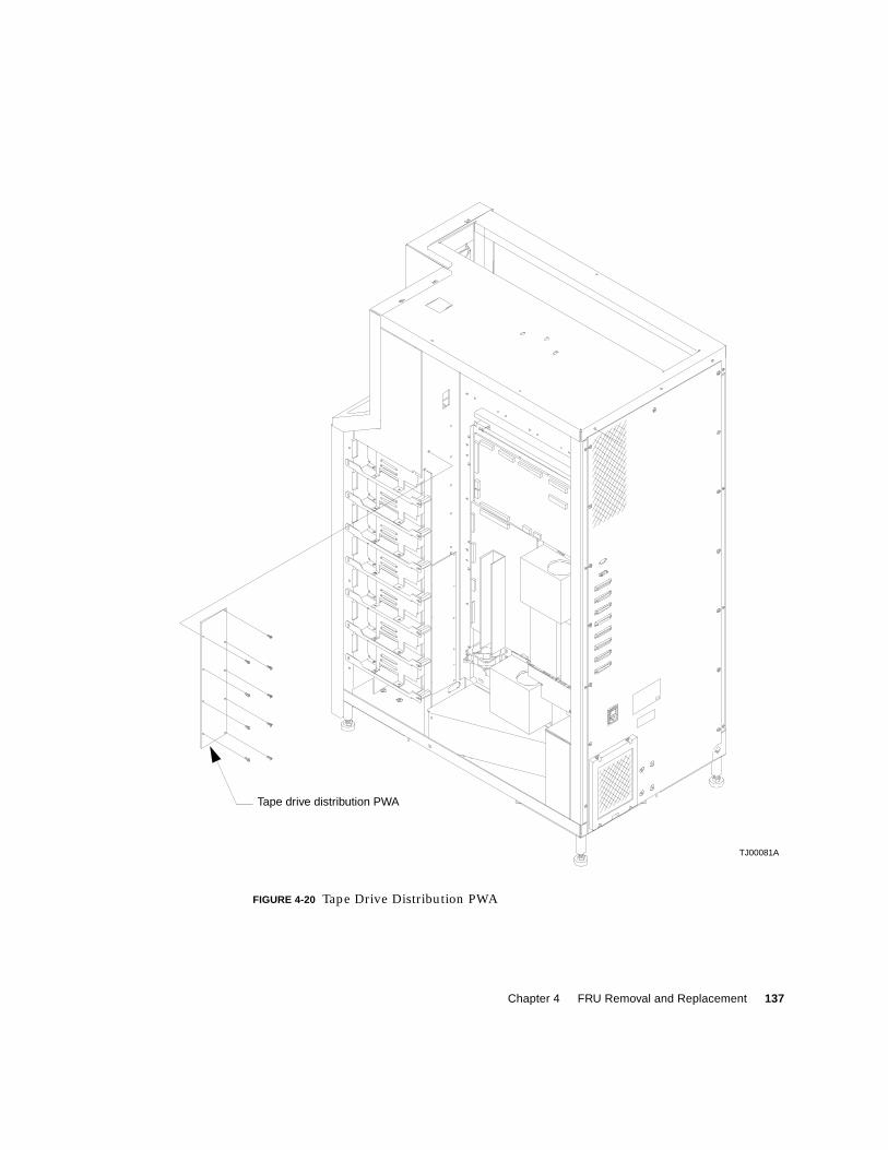
Chapter 4 FRU Removal and Replacement 137
FIGURE 4-20 Tape Drive Distribution PWA
Tape drive distribution PWA
TJ00081A

138 Sun Enterprise Tape Library 7/3500 Field Service Manual • July 1997
Tape Drive MUX PWA
Required Tools
Phillips screwdriver
▼ To Remove the Tape Drive MUX PWA
1. Remove power from the library.
Caution – DO NOT disconnect the power cord from facility power or the library.
The power cord is the only means of grounding the chassis and helping to prevent
electrostatic discharge (ESD) damage.
2. Connect your ESD wrist grounding strap to the closest grounding point on theframe of the library.
3. Remove the right cosmetic panels as shown in “Top, Right, and Left Panels” onpage 92.
4. Disconnect all cabling between the tape drive MUX PWA and the tape drives.
5. Disconnect the cable at J20 on the PWA and tag it.
Caution – The cable at J20 must be replaced to J20. If it is connected to J19, the
library will be damaged. Be sure to tag this cable when it is removed.
6. Disconnect cables at J2, J16, J17, and J18, and J21 on the PWA.
7. Remove the PWA mounting screws, and remove the PWA.
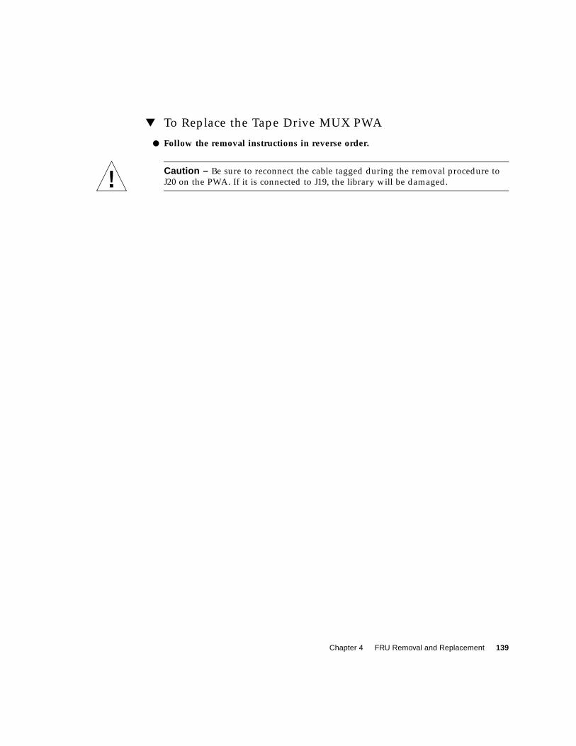
Chapter 4 FRU Removal and Replacement 139
▼ To Replace the Tape Drive MUX PWA
● Follow the removal instructions in reverse order.
Caution – Be sure to reconnect the cable tagged during the removal procedure to
J20 on the PWA. If it is connected to J19, the library will be damaged.
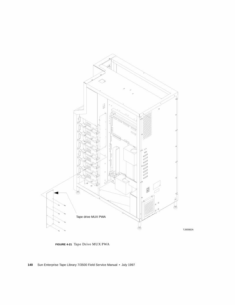
140 Sun Enterprise Tape Library 7/3500 Field Service Manual • July 1997
FIGURE 4-21 Tape Drive MUX PWA
Tape drive MUX PWA
TJ00082A

Chapter 4 FRU Removal and Replacement 141
4OC
Control Panel Assembly
Required Tools
Phillips screwdriver
▼ To Remove the Control Panel Assembly
1. Remove power from the library.
Caution – DO NOT disconnect the power cord from facility power or the library.
The power cord is the only means of grounding the chassis and helping to prevent
electrostatic discharge (ESD) damage.
2. Connect your ESD wrist grounding strap to the closest grounding point on theframe of the library.
3. Remove the top, left, and right cosmetic panels as shown in “Top, Right, and LeftPanels” on page 92.
4. Remove the front cover as shown in “Top, Right, and Left Panels” on page 92.
5. With the front panel removed, locate the control panel assembly from within thefront panel. (FIGURE 4-22).
6. Remove connector A3_J1 from the control panel assembly.
7. Remove the self-locking nuts that retain the control panel assembly.
8. Remove the ESD guard.
9. Pull the control panel assembly down and out to remove.
▼ To Replace the Control Panel Assembly
● Follow the removal instructions in reverse order.
142 Sun Enterprise Tape Library 7/3500 Field Service Manual • July 1997
▼ To Make Adjustments Required After Replacement
● Auto calibrate the load port.
FIGURE 4-22 Control Panel Assembly
Control panel
Front panel
TJ00084A
E
E
E-EVIEW
assembly
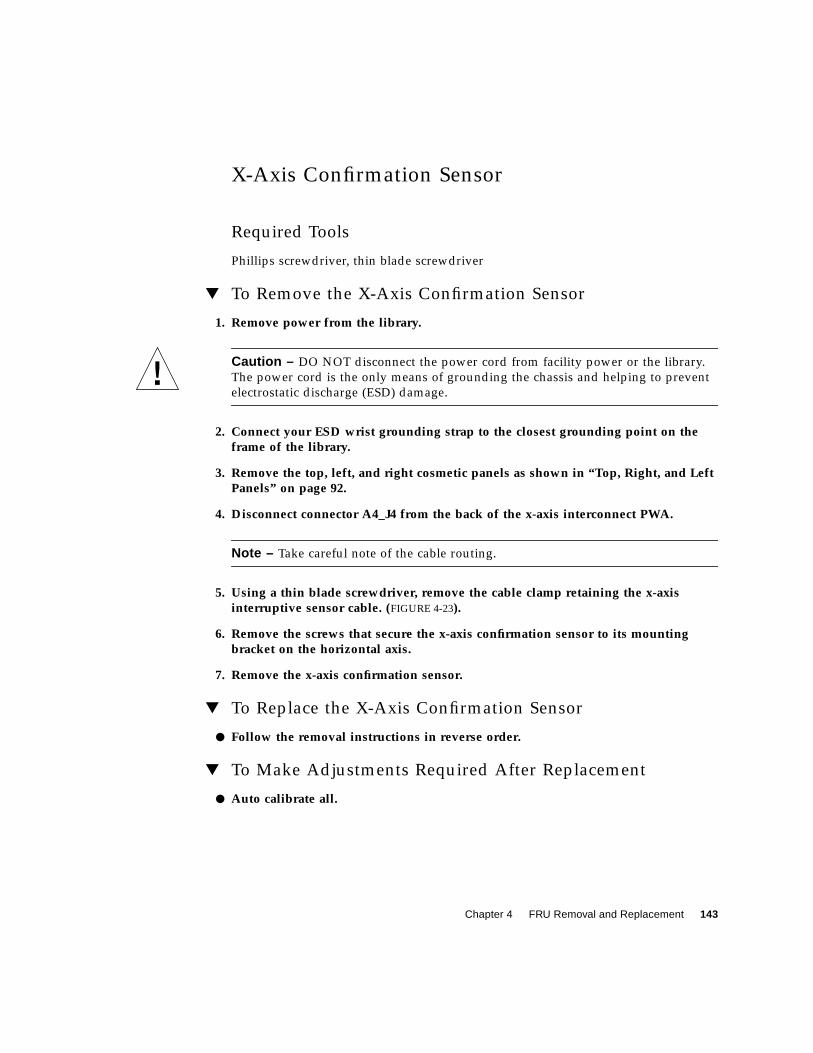
Chapter 4 FRU Removal and Replacement 143
X-Axis Confirmation Sensor
Required Tools
Phillips screwdriver, thin blade screwdriver
▼ To Remove the X-Axis Confirmation Sensor
1. Remove power from the library.
Caution – DO NOT disconnect the power cord from facility power or the library.
The power cord is the only means of grounding the chassis and helping to prevent
electrostatic discharge (ESD) damage.
2. Connect your ESD wrist grounding strap to the closest grounding point on theframe of the library.
3. Remove the top, left, and right cosmetic panels as shown in “Top, Right, and LeftPanels” on page 92.
4. Disconnect connector A4_J4 from the back of the x-axis interconnect PWA.
Note – Take careful note of the cable routing.
5. Using a thin blade screwdriver, remove the cable clamp retaining the x-axisinterruptive sensor cable. (FIGURE 4-23).
6. Remove the screws that secure the x-axis confirmation sensor to its mountingbracket on the horizontal axis.
7. Remove the x-axis confirmation sensor.
▼ To Replace the X-Axis Confirmation Sensor
● Follow the removal instructions in reverse order.
▼ To Make Adjustments Required After Replacement
● Auto calibrate all.
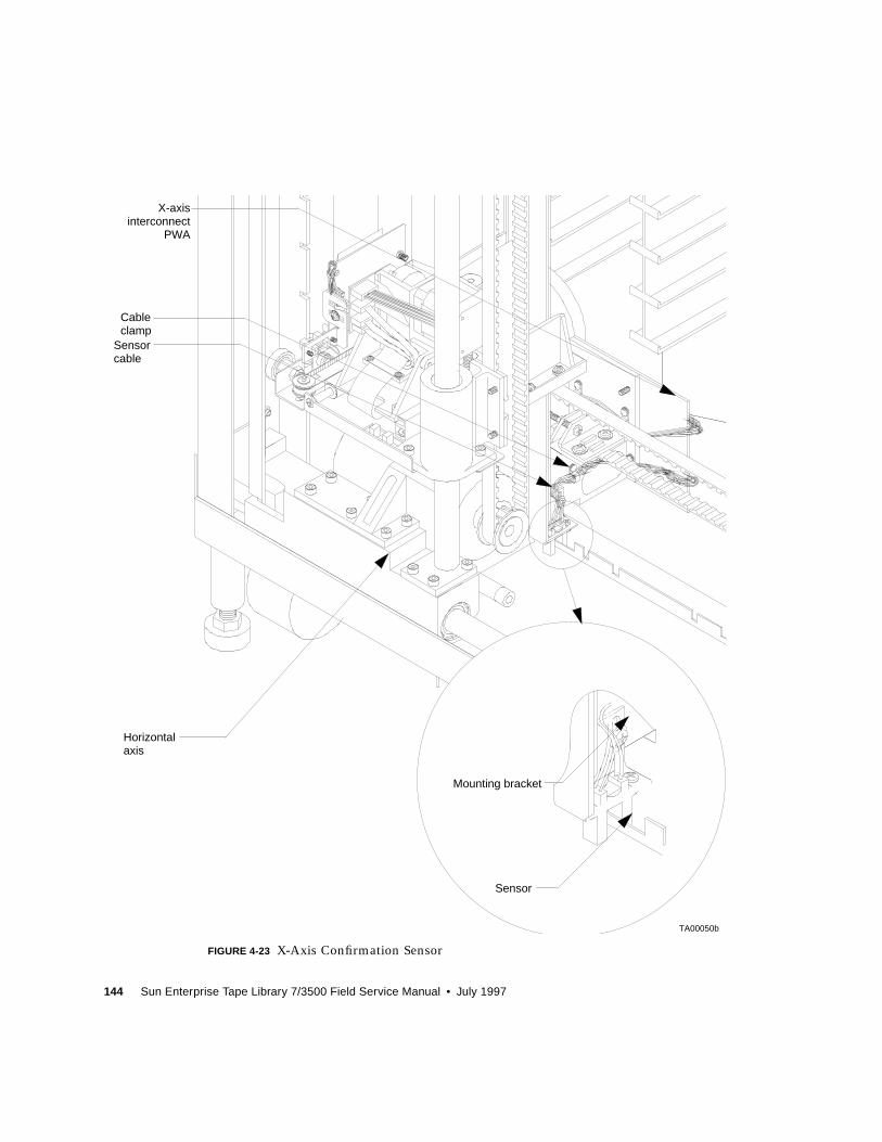
144 Sun Enterprise Tape Library 7/3500 Field Service Manual • July 1997
FIGURE 4-23 X-Axis Confirmation Sensor
TA00050b
X-axis
Cable
Sensor
Sensor
Mounting bracket
Horizontal
interconnectPWA
clamp
cable
axis
Chapter 4 FRU Removal and Replacement 145
Robotics Controller PWA
Required Tools
Phillips screwdriver
▼ To Remove the Robotics Controller PWA
1. If possible, record the contents of the NVRAM (U38) (for example., calibrationvalues, statistics, and so forth).
2. Remove power from the library.
Caution – DO NOT disconnect the power cord from facility power or the library.
The power cord is the only means of grounding the chassis and helping to prevent
electrostatic discharge (ESD) damage.
3. Connect your ESD wrist grounding strap to the closest grounding point on theframe of the library.
4. Remove the top, left, and right cosmetic panels as shown in “Top, Right, and LeftPanels” on page 92.
5. From the right side of the library, locate the robotics controller PWA on the upperhalf of the controller electronics assembly. (FIGURE 4-24).
6. Disconnect connectors A1_J1, A1_J3, A1_J6, A1_J7, A1_J8, A1_J9, A1_J11 andA1_J15.
Note – To prevent lost and hard to retrieve screws, cover the fan opening directly
below the controller electronics assembly.
7. Remove the screws that secure the robotics controller PWA and lift out.
Note – Hold the robotics controller PWA securely when removing the last mounting
screw.
146 Sun Enterprise Tape Library 7/3500 Field Service Manual • July 1997
▼ To Replace the Robotics Controller PWA
Note – If possible, swap NVRAM (U38) from the removed robotics controller PWA
to replacement PWA to retain the configuration and statistics data of the library.
1. Follow the removal instructions in reverse order.
2. Initialize NVRAM.
3. Configure for existing drives.
4. Calibrate the drives.
5. Calibrate all.
6. Cycle power.
▼ To Make Adjustments Required After Replacement
1. Using the diagnostic software program, perform a System Info (see the Sun ETL 7/3500 Library Diagnostic Software User’s Manual). Determine if the firmware level ofthe replacement PWA is the same or higher than the replaced PWA.
2. If the firmware level of the replacement PWA is not the same or higher than thereplaced PWA, follow the firmware flash download procedure.
Note – The calibration values are kept in NVRAM on the robotics controller PWA. It
is recommended that NVRAM be initialized before performing the calibration
procedures.
3. If the NVRAM (U38) was not swapped, using the DSP, perform an Init Nov-VolRAM from the configuration menu.
4. From the library menu, perform the Cal All from the Calibration menu.
Note – If the NVRAM is not salvageable, you should note in your records that the
statistics data in the NVRAM has been lost.
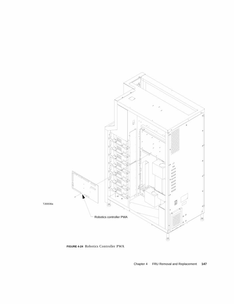
Chapter 4 FRU Removal and Replacement 147
FIGURE 4-24 Robotics Controller PWA
TJ00036a
Robotics controller PWA
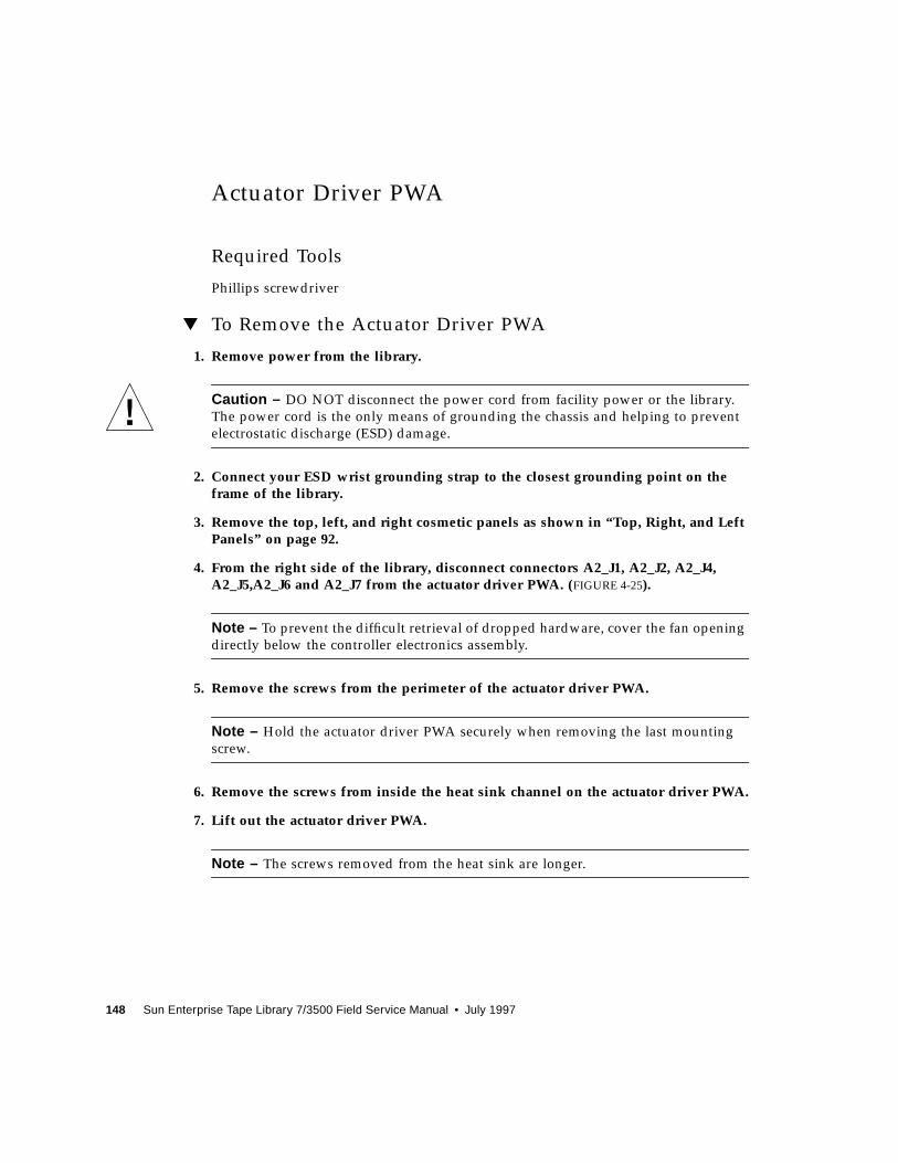
148 Sun Enterprise Tape Library 7/3500 Field Service Manual • July 1997
Actuator Driver PWA
Required Tools
Phillips screwdriver
▼ To Remove the Actuator Driver PWA
1. Remove power from the library.
Caution – DO NOT disconnect the power cord from facility power or the library.
The power cord is the only means of grounding the chassis and helping to prevent
electrostatic discharge (ESD) damage.
2. Connect your ESD wrist grounding strap to the closest grounding point on theframe of the library.
3. Remove the top, left, and right cosmetic panels as shown in “Top, Right, and LeftPanels” on page 92.
4. From the right side of the library, disconnect connectors A2_J1, A2_J2, A2_J4,A2_J5,A2_J6 and A2_J7 from the actuator driver PWA. (FIGURE 4-25).
Note – To prevent the difficult retrieval of dropped hardware, cover the fan opening
directly below the controller electronics assembly.
5. Remove the screws from the perimeter of the actuator driver PWA.
Note – Hold the actuator driver PWA securely when removing the last mounting
screw.
6. Remove the screws from inside the heat sink channel on the actuator driver PWA.
7. Lift out the actuator driver PWA.
Note – The screws removed from the heat sink are longer.

Chapter 4 FRU Removal and Replacement 149
▼ To Replace the Actuator Driver PWA
1. Follow the removal instructions in reverse order.
2. Take note of the longer screws used to mount the actuator driver PWA through theheat sink.
150 Sun Enterprise Tape Library 7/3500 Field Service Manual • July 1997
FIGURE 4-25 Actuator Driver PWA
TJ00037aActuator driver PWA

Chapter 4 FRU Removal and Replacement 151
PC Logic Power Supply Assembly
Each library has two PC logic power supply assemblies. The following procedure
applies for each power supply assembly.
Required Tools
Phillips screwdriver
▼ To Remove the Top PC Logic Power Supply
1. Remove power from the library.
Caution – DO NOT disconnect the power cord from facility power or the library.
The power cord is the only means of grounding the chassis and helping to prevent
electrostatic discharge (ESD) damage.
2. Connect your ESD wrist grounding strap to the closest grounding point on theframe of the library.
3. Remove the top and right cosmetic panels as shown in “Top, Right, and LeftPanels” on page 92.
4. Disconnect A1_J11 and A1_J15 from the robotics controller PWA.
5. Disconnect connectors P1_J2, P1_J3, P1_J4, and P1_J5 from the PC logic powersupply.
Note – To prevent loosing removed hardware, cover the fan opening directly below
the controller electronics assembly.
6. Remove the screws that secure the PC logic power supply and brackets to thecontroller electronics assembly.
Note – Hold the PC logic power supply assembly securely when removing the last
mounting screw.
7. Detach the mounting bracket from power supply by removing the screws).
8. Disconnect the AC power.

152 Sun Enterprise Tape Library 7/3500 Field Service Manual • July 1997
▼ To Replace the Top PC Logic Power Supply
● Follow the removal instructions in reverse order.
▼ To Remove the Bottom PC Logic Power Supply
1. Detach the connectors from the tape drive MUX PWA.
2. Disconnect the AC power.
▼ To Replace the Bottom PC Logic Power Supply
● Follow the removal instructions in reverse order.
▼ To Make Adjustments Required After Replacement
1. Turn off AC power and remove the PC power supply cover (remove the screws onthe top of the power supply).
2. Verify that +5V, +12V, and -12V fuses are replaced and that no shorts exist.
3. Hook a DVM up to +5V and GND test points on the robotics controller.
4. Turn on AC power.
5. Locate potentiometer in PC power supply main board.
6. Adjust +5V to between +5.05V and +5.15VDC.
7. Verify that +12V is between +11.5V and +12.5V. If not, adjust +12V within limitsand reverify that the +5V is within limits.
8. If power cannot be adjusted, replace power supply and repeat procedure.
▼ To Troubleshoot
● Make sure the connectors on the robotics controller PWA are seated properly.
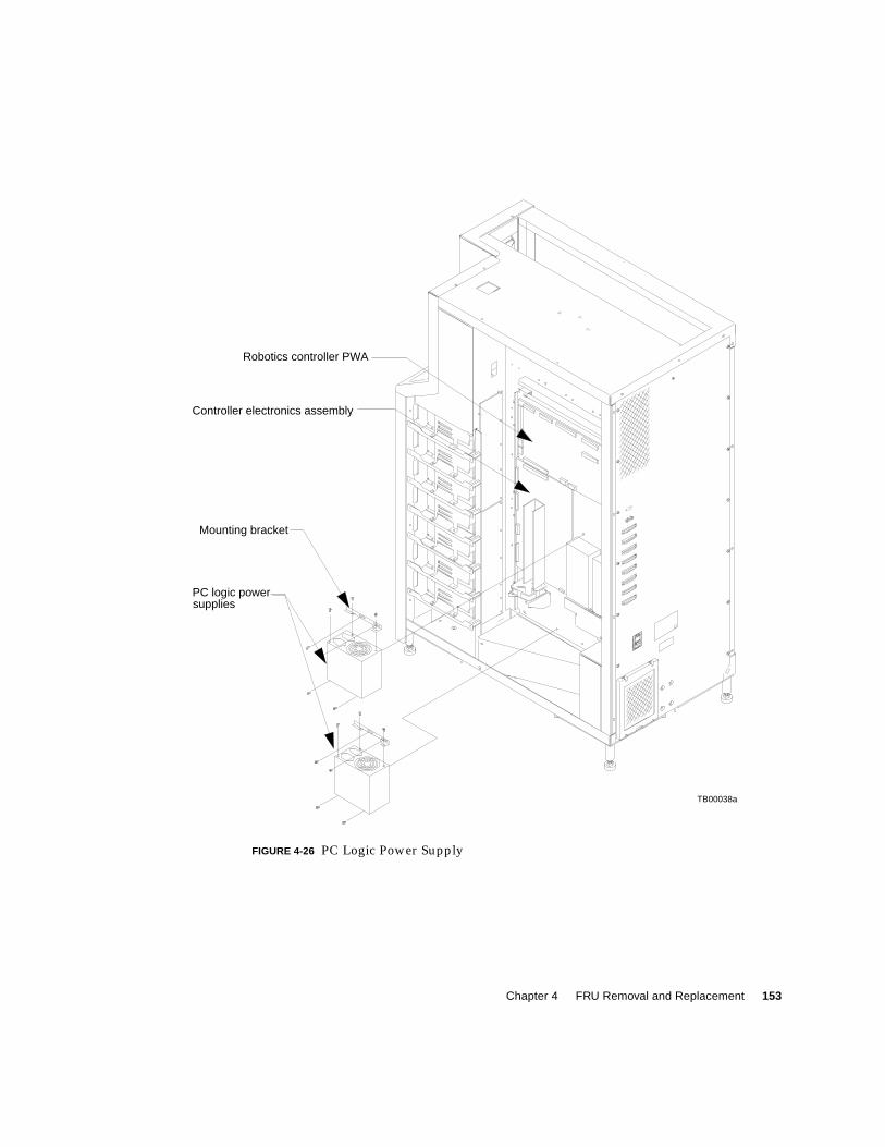
Chapter 4 FRU Removal and Replacement 153
FIGURE 4-26 PC Logic Power Supply
Mounting bracket
PC logic power
Controller electronics assembly
Robotics controller PWA
supplies
TB00038a
154 Sun Enterprise Tape Library 7/3500 Field Service Manual • July 1997
Motor Power Supply Assembly
Each library has two motor power supply assemblies. The following procedure
applies for each power supply assembly.
Required Tools
Phillips screwdriver
▼ To Remove the Motor Power Supply Assembly
1. Remove power from the library.
Caution – DO NOT disconnect the power cord from facility power or the library.
The power cord is the only means of grounding the chassis and helping to prevent
electrostatic discharge (ESD) damage.
2. Connect your ESD wrist grounding strap to the closest grounding point on theframe of the library.
3. Remove the top and right cosmetic panels as shown in “Top, Right, and LeftPanels” on page 92.
4. On the selected motor power supply, loosen all of the terminals on the powersupply barrier strip.
5. Remove the wires.
Note – Make note of each wire and its connection point.
6. Remove the controller electronics assembly. See “Controller ElectronicsAssembly” on page 97 for removal instructions.
7. From the back of the controller electronics assembly, remove the lower mountingscrew from the motor power supply.
Note – If you are replacing PS2, also remove the over voltage protector.
8. Loosen the upper mounting screw.
9. Lift out the motor power supply.

Chapter 4 FRU Removal and Replacement 155
▼ To Replace the Motor Power Supply Assembly
● Follow the removal instructions in reverse order.
▼ To Troubleshoot
● Check the motor power supply barrier strip terminal connections.
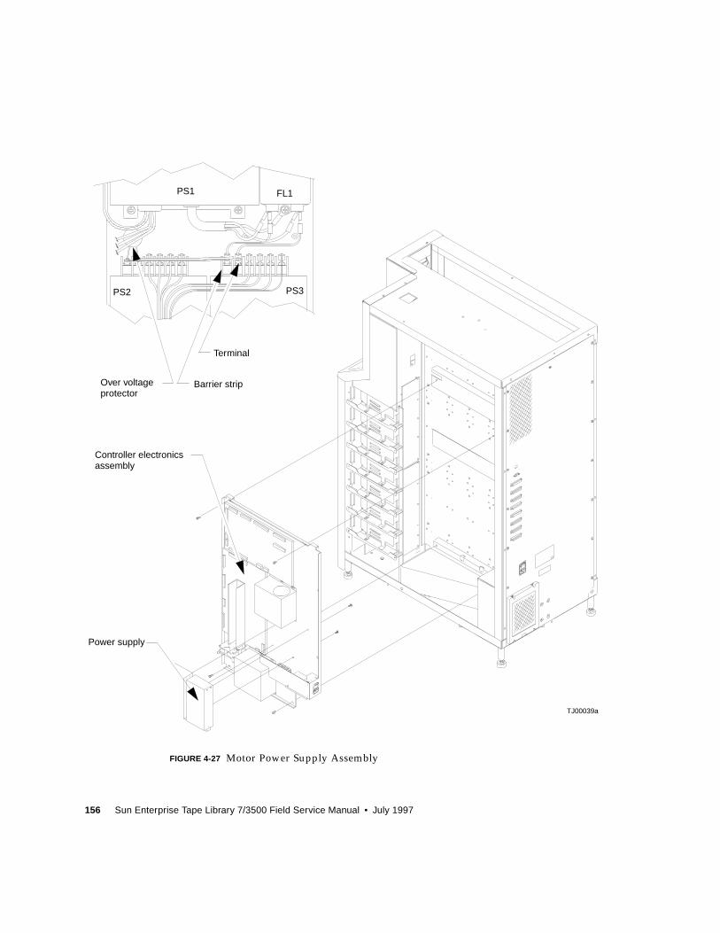
156 Sun Enterprise Tape Library 7/3500 Field Service Manual • July 1997
FIGURE 4-27 Motor Power Supply Assembly
PS1
PS2 PS3
FL1
Terminal
Barrier stripOver voltage
TJ00039a
Power supply
protector
Controller electronicsassembly
Chapter 4 FRU Removal and Replacement 157
Light Bulb
Required Tools
Phillips screwdriver
▼ To Remove the Light Bulb
1. Remove power from the library.
Caution – DO NOT disconnect the power cord from facility power or the library.
The power cord is the only means of grounding the chassis and helping to prevent
electrostatic discharge (ESD) damage.
2. Connect your ESD wrist grounding strap to the closest grounding point on theframe of the library.
3. Remove the top and right cosmetic panels as shown in “Top, Right, and LeftPanels” on page 92.
4. Disconnect power from the tape drive distribution PWA.
5. Remove the screws that secure the light bulb assembly. See “Light BulbAssembly” on page 158.
6. Lift out the light bulb assembly.
7. Pop off the cover.
8. Remove the bulb.
▼ To Replace the Light Bulb
● Follow the removal instructions in reverse order.
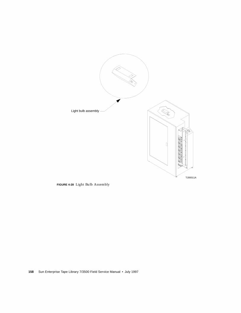
158 Sun Enterprise Tape Library 7/3500 Field Service Manual • July 1997
FIGURE 4-28 Light Bulb Assembly
TJ00011A
Light bulb assembly
Chapter 4 FRU Removal and Replacement 159
Reassembling the Library
Replacing the Cosmetic Panels
Use the procedures below along with FIGURE 4-1 on page 92 and FIGURE 4-2 on
page 95 to replace the cosmetic panels.
▼ To Replace the Front Panel
Caution – You must replace the front panel before replacing the top, left or right
panels.
1. Position the front panel at the front of the library.
2. Reconnect control panel ribbon connector A3_J1.
3. From the front of the library, pick up the front panel and replace it on the libraryframe (from bottom to top).
4. Reconnect the remaining miscellaneous sensors cable assembly connectors.
a. Plug SW1 blade lug black wire onto the bottom (common) spade of SW1.
b. Plug SW1 blade lug white wire onto the top (N.C.) spade of SW1.
c. Plug SW2 blade lug black wire onto the bottom (common) spade of SW2.
d. Plug SW2 blade lug white wire onto the top (N.C.) spade of SW2.
e. Reconnect the front door interlock switch in-line connector SW2_J1.
f. Reconnect the load port solenoid in-line connector SOL_J1.
5. Reinstall the mounting screws.
6. From the right side of the library, reinstall the EMI cover.
▼ To Replace the Left Panel
1. Rest the top lip of the left panel on the top of the library frame.
2. Push the panel towards the front of the library and insert the frame buckles intothe retention tabs.
160 Sun Enterprise Tape Library 7/3500 Field Service Manual • July 1997
3. At the rear of the library, insert and tighten the screws to secure the left panel tothe rear of the library frame.
▼ To Replace the Right Panel
1. Rest the top lip of the right panel on the top of the library frame.
2. At the rear of the library, insert and tighten the screws to secure the right panel tothe rear of the library frame.
3. Insert and tighten the screws behind the drive bay door.
▼ To Replace the Top Panel
Caution – You must replace the front, left, and right panels before replacing the top
panel.
1. Place the panel on top of the library.
2. Push the panel towards the front of the library and insert the retention tab intothe slot.
3. At the rear of the library, insert and tighten the screws to secure the top panel tothe library frame.
▼ To Apply Power to the Library
1. Verify the following:
■ Front door and load port closed
■ All outer skins attached
■ All rear panel connections secured
2. At the rear panel, set the POWER switch to the | (on) position.
3. After several seconds, verify that SDA shows System Online.
Note – “System Online” is only displayed if the library power-on state is configured
for online. Otherwise, System Offline (STANDBY) is displayed in the SDA.

Chapter 4 FRU Removal and Replacement 161
▼ To Place the Library Online
1. With the library power applied and the SDA showing System Offline, press thecontrol panel STANDBY button.
2. Verify that System Online is displayed in the SDA.

162 Sun Enterprise Tape Library 7/3500 Field Service Manual • July 1997
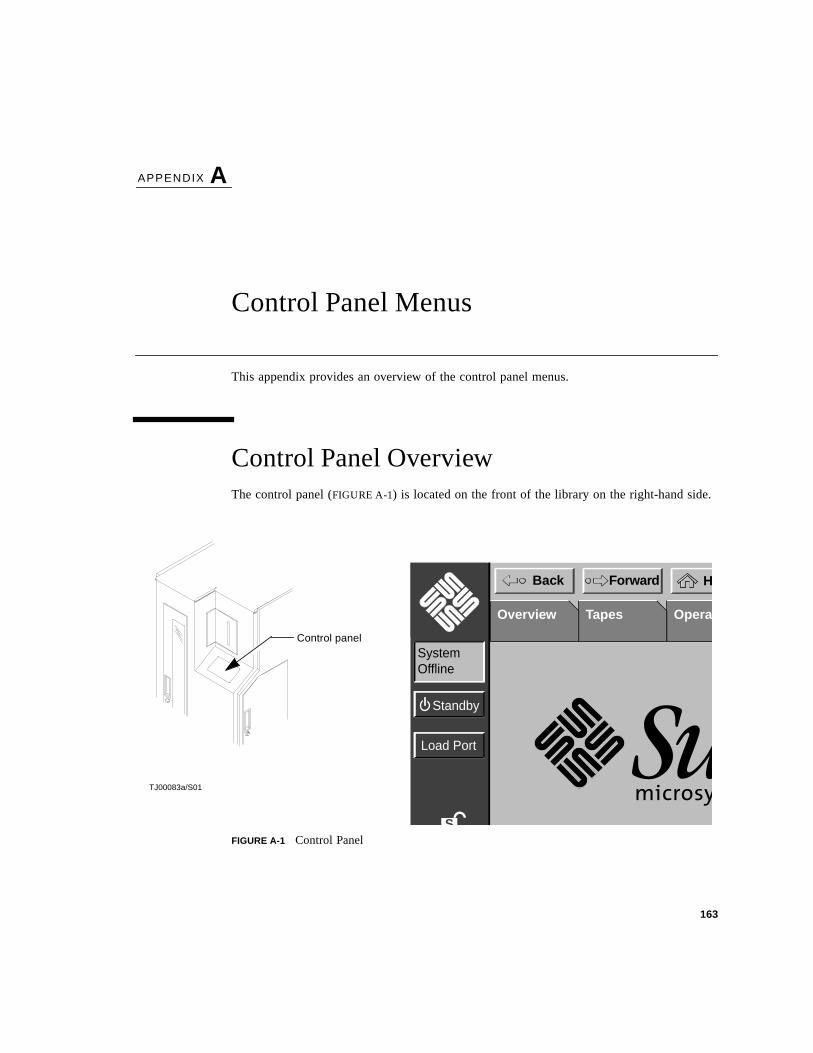
163
APPENDIX A
Control Panel Menus
This appendix provides an overview of the control panel menus.
Control Panel OverviewThe control panel (FIGURE A-1) is located on the front of the library on the right-hand side.
FIGURE A-1 Control Panel
Control panel
TJ00083a/S01
S
Load Port
Standby
HBack Forward
SystemOffline
TapesOverview Operat
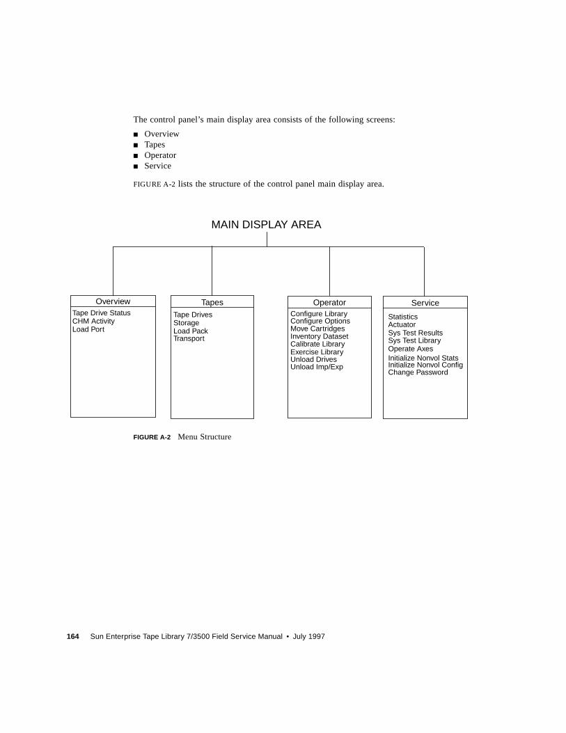
164 Sun Enterprise Tape Library 7/3500 Field Service Manual • July 1997
The control panel’s main display area consists of the following screens:
■ Overview■ Tapes■ Operator■ Service
FIGURE A-2 lists the structure of the control panel main display area.
FIGURE A-2 Menu Structure
Configure LibraryConfigure OptionsMove CartridgesInventory Dataset
StatisticsActuatorSys Test ResultsSys Test LibraryOperate AxesInitialize Nonvol StatsInitialize Nonvol Config
Overview Tapes Operator Service
MAIN DISPLAY AREA
Calibrate Library
Tape Drive StatusCHM ActivityLoad Port
Tape DrivesStorageLoad PackTransport
Exercise LibraryUnload DrivesUnload Imp/Exp
Change Password
Appendix A Control Panel Menus 165
Control Panel NavigationThe control panel uses a touch-screen for convenient navigation. To activate a command oropen a screen, simply touch the appropriate “button” on the screen. You can also movebackward and forward through screens opened previously by pressing the Back and Forwardbuttons.
The Home button returns the control panel to the initial screen.
Using Library Controls
Library controls are located in the vertical bar on the left side of the control panel. They arealways available, even when using the main display area to open operator- or service-relatedscreens.
Opening a Screen
To open one of the four main screens (Overview, Tapes, Operator, or Service), press theappropriate tab near the top of the control panel. That screen is displayed in the main area.
Note – If you press either the Operator or Service tabs, a dialog box is displayed requestinga password. You must enter a password to display these screens.
Once the desired screen is displayed, you can view information or press buttons to executecommands and open other screens.
Exiting a Screen
You can exit any screen by pressing the Back or Home buttons.
If a command is executing, a dialog box is displayed in the main area with an ABORTbutton. Pressing this button cancels the command and stops the ongoing operation. (Pressingthe Back or Home button is still required to exit the screen associated with the dialog box.)
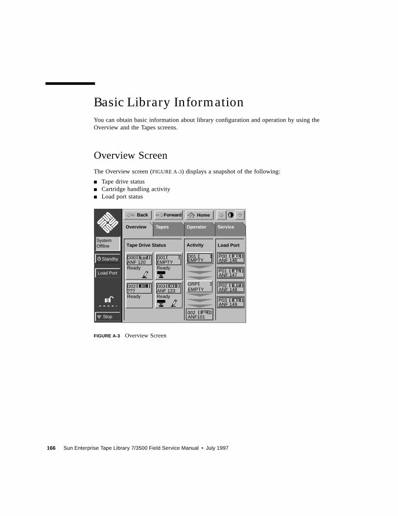
166 Sun Enterprise Tape Library 7/3500 Field Service Manual • July 1997
Basic Library Information
You can obtain basic information about library configuration and operation by using theOverview and the Tapes screens.
Overview Screen
The Overview screen (FIGURE A-3) displays a snapshot of the following:
■ Tape drive status■ Cartridge handling activity■ Load port status
FIGURE A-3 Overview Screen
S
Load Port
Stop
Standby
HomeBack Forward
SystemOffline
TapesOverview Operator ServiceOverview
ANF 146P00
ANF 147P01
ANF 148P02
ANF 149P03
Load Port
EMPTYGRP
ANF101002
EMPTYD01
Activity
Ready
D00ANF 120
Tape Drive Status
Ready
D01EMPTY
Ready
D02???
Ready
D03ANF 123
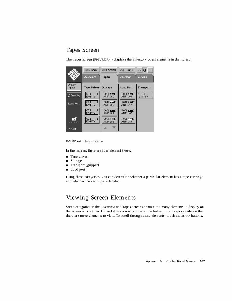
Appendix A Control Panel Menus 167
Tapes Screen
The Tapes screen (FIGURE A-4) displays the inventory of all elements in the library.
FIGURE A-4 Tapes Screen
In this screen, there are four element types:
■ Tape drives■ Storage■ Transport (gripper)■ Load port
Using these categories, you can determine whether a particular element has a tape cartridgeand whether the cartridge is labeled.
Viewing Screen Elements
Some categories in the Overview and Tapes screens contain too many elements to display onthe screen at one time. Up and down arrow buttons at the bottom of a category indicate thatthere are more elements to view. To scroll through these elements, touch the arrow buttons.
S
Load Port
Stop
Standby
HomeBack Forward
SystemOffline
DatasetOverview Operator ServiceTapes
Load PortStorageTape Drives Transport
ANF 146P00
ANF 147P01
ANF 148P02
ANF 149P03
ANF 099000
ANF 100001
ANF 101002
ANF 102003
EMPTY00
EMPTY01
EMPTY02
EMPTY03
EMPTYGRP
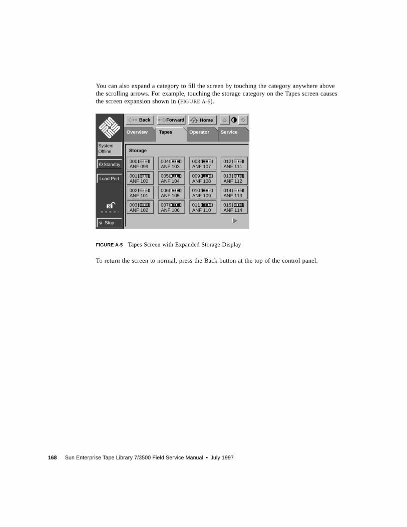
168 Sun Enterprise Tape Library 7/3500 Field Service Manual • July 1997
You can also expand a category to fill the screen by touching the category anywhere abovethe scrolling arrows. For example, touching the storage category on the Tapes screen causesthe screen expansion shown in (FIGURE A-5).
FIGURE A-5 Tapes Screen with Expanded Storage Display
To return the screen to normal, press the Back button at the top of the control panel.
S
Load Port
Stop
Standby
HomeBack Forward
SystemOffline
DatasetOverview Operator ServiceTapes
Storage
ANF 099000
ANF 100001
ANF 101002
ANF 102003
ANF 103004
ANF 104005
ANF 105006
ANF 106007
ANF 107008
ANF 108009
ANF 109010
ANF 110011
ANF 111012
ANF 112013
ANF 113014
ANF 114015
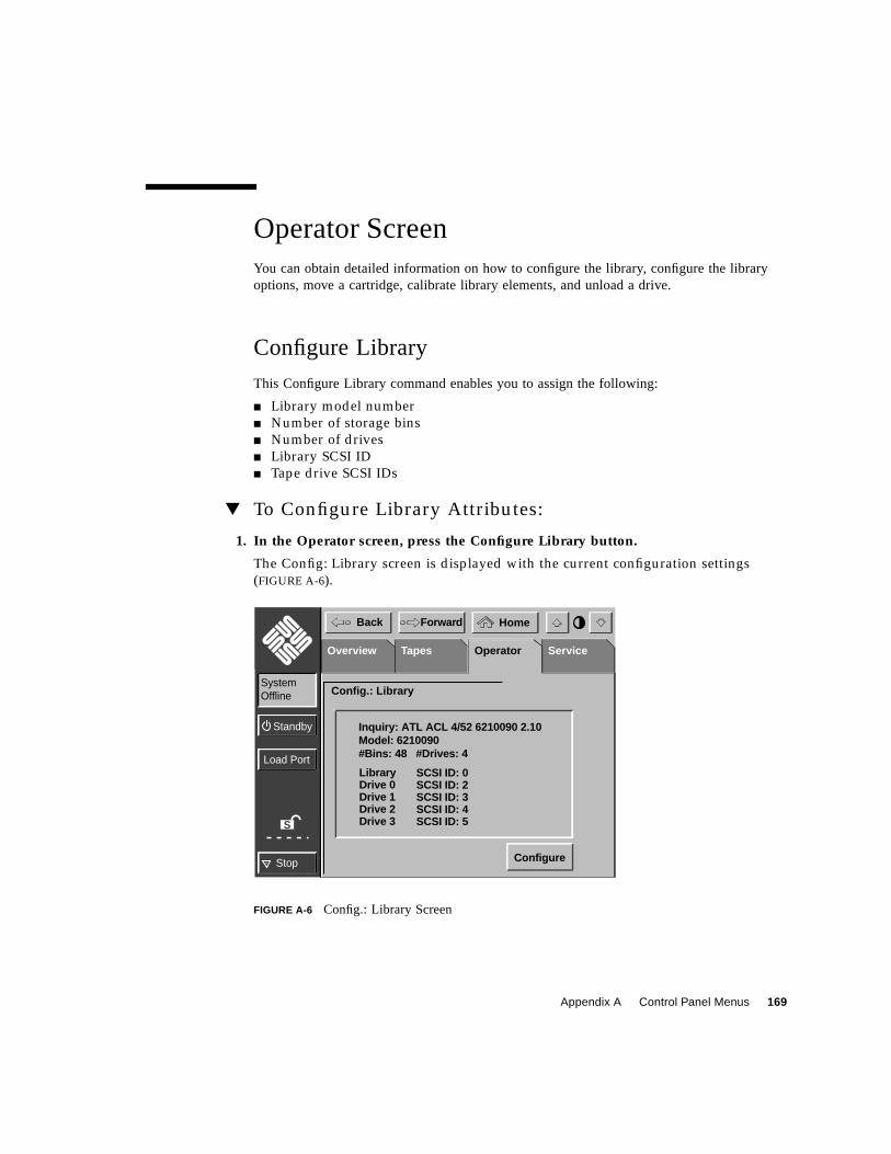
Appendix A Control Panel Menus 169
Operator ScreenYou can obtain detailed information on how to configure the library, configure the libraryoptions, move a cartridge, calibrate library elements, and unload a drive.
Configure Library
This Configure Library command enables you to assign the following:
■ Library model number
■ Number of storage bins
■ Number of drives
■ Library SCSI ID
■ Tape drive SCSI IDs
▼ To Configure Library Attributes:
1. In the Operator screen, press the Configure Library button.
The Config: Library screen is displayed with the current configuration settings
(FIGURE A-6).
FIGURE A-6 Config.: Library Screen
S
Load Port
Stop
Standby
HomeBack Forward
SystemOffline
TapesOverview Operator ServiceOperator
Config.: Library
Configure
Inquiry: ATL ACL 4/52 6210090 2.10Model: 6210090#Bins: 48 #Drives: 4
SCSI ID: 0SCSI ID: 2SCSI ID: 3SCSI ID: 4SCSI ID: 5
Library Drive 0 Drive 1Drive 2Drive 3
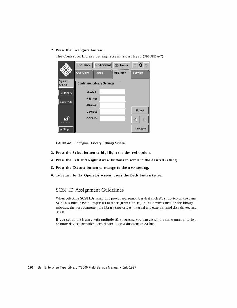
170 Sun Enterprise Tape Library 7/3500 Field Service Manual • July 1997
2. Press the Configure button.
The Configure: Library Settings screen is displayed (FIGURE A-7).
FIGURE A-7 Configure: Library Settings Screen
3. Press the Select button to highlight the desired option.
4. Press the Left and Right Arrow buttons to scroll to the desired setting.
5. Press the Execute button to change to the new setting.
6. To return to the Operator screen, press the Back button twice.
SCSI ID Assignment Guidelines
When selecting SCSI IDs using this procedure, remember that each SCSI device on the sameSCSI bus must have a unique ID number (from 0 to 15). SCSI devices include the libraryrobotics, the host computer, the library tape drives, internal and external hard disk drives, andso on.
If you set up the library with multiple SCSI busses, you can assign the same number to twoor more devices provided each device is on a different SCSI bus.
S
Load Port
Stop
Standby
HomeBack Forward
SystemOffline
TapesOverview Operator ServiceOperator
Configure: Library Settings
_Model:
# Bins:
#Drives:
Device:
SCSI ID:
Execute
Select
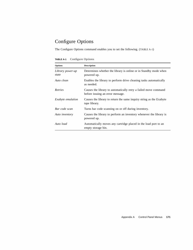
Appendix A Control Panel Menus 171
Configure Options
The Configure Options command enables you to set the following. (TABLE A-1)
TABLE A-1 Configure Options
Options Description
Library power-upstate
Determines whether the library is online or in Standby mode whenpowered up.
Auto clean Enables the library to perform drive cleaning tasks automaticallyas needed.
Retries Causes the library to automatically retry a failed move commandbefore issuing an error message.
Exabyte emulation Causes the library to return the same inquiry string as the Exabytetape library.
Bar code scan Turns bar code scanning on or off during inventory.
Auto inventory Causes the library to perform an inventory whenever the library ispowered up.
Auto load Automatically moves any cartridge placed in the load port to anempty storage bin.
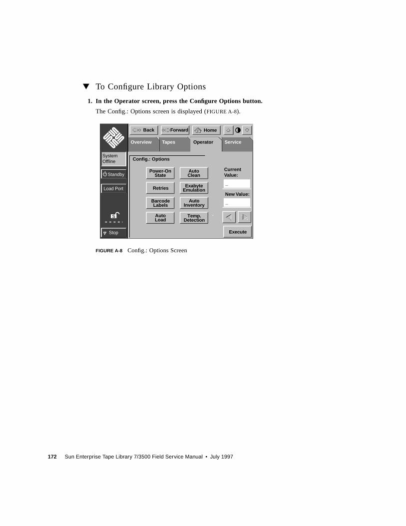
172 Sun Enterprise Tape Library 7/3500 Field Service Manual • July 1997
▼ To Configure Library Options
1. In the Operator screen, press the Configure Options button.
The Config.: Options screen is displayed (FIGURE A-8).
FIGURE A-8 Config.: Options Screen
S
Load Port
Stop
Standby
HomeBack Forward
SystemOffline
TapesOverview Operator ServiceOperator
Config.: Options
Execute
AutoClean
Power-OnState
ExabyteEmulationRetries
AutoInventory
BarcodeLabels
Temp.Detection
AutoLoad
New Value:
_
CurrentValue:
_
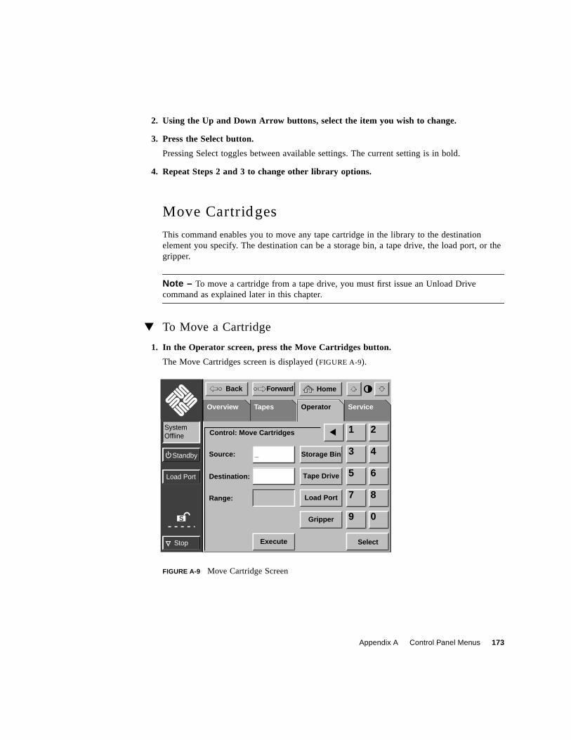
Appendix A Control Panel Menus 173
2. Using the Up and Down Arrow buttons, select the item you wish to change.
3. Press the Select button.
Pressing Select toggles between available settings. The current setting is in bold.
4. Repeat Steps 2 and 3 to change other library options.
Move Cartridges
This command enables you to move any tape cartridge in the library to the destinationelement you specify. The destination can be a storage bin, a tape drive, the load port, or thegripper.
Note – To move a cartridge from a tape drive, you must first issue an Unload Drivecommand as explained later in this chapter.
▼ To Move a Cartridge
1. In the Operator screen, press the Move Cartridges button.
The Move Cartridges screen is displayed (FIGURE A-9).
FIGURE A-9 Move Cartridge Screen
S
Load Port
Stop
Standby
HomeBack Forward
SystemOffline
TapesOverview Operator ServiceOperator
Control: Move Cartridges
Source:
Destination:
Range:
Storage Bin_
Tape Drive
Load Port
Execute
Gripper
1 2
3 4
5 6
7 8
9 0
Select
174 Sun Enterprise Tape Library 7/3500 Field Service Manual • July 1997
2. Identify the source element (that is, the element with the tape cartridge to be moved):
a. Press the appropriate element type button (Storage Bin, Tape Drive, Load Port, orGripper).
When you press an element type button, the range of addresses is displayed in the Rangedisplay.
b. Using the keypad, enter the address for the source element
The source information is displayed in the Source input field.
c. When you have finished entering the address, press the Destination input field.
The Destination input field becomes active.
3. Select a destination for the cartridge:
a. Press the appropriate element type button (Storage Bin, Tape Drive, Load Port, orGripper).
When you press an element type button, the range of addresses is displayed in the Rangedisplay.
b. Using the keypad, enter the address for the destination element.
The destination information is displayed in the Destination input field.
c. When you have finished entering the address, press the Execute button.
This initiates the move command from the source element to the destination element. An“In Progress” dialog box is displayed.
The dialog box remains on the screen until the move is completed, aborted by pressing theABORT button, or stopped due to an error condition.
Inventory Tapes
This command identifies all tape cartridges in the library by bar code label and determinestheir location. Elements that are empty or that contain unlabeled cartridges are marked assuch.
▼ To Perform an Inventory
● Press the Inventory Tapes button in the Operator screen.
An “In Progress” screen is displayed.
The dialog box remains on the screen until the inventory is completed, aborted by pressingthe ABORT button, or stopped due to an error condition.
Appendix A Control Panel Menus 175
Calibrate Library
This command enables you to calibrate the storage bins, the tape drives, the load port, or theentire library. The library should be calibrated during initial installation and after anymaintenance procedure.
▼ To Calibrate Library Elements
1. In the Operator page, press the Calibrate Library button.
The Calibrate Library screen is displayed (FIGURE A-10).
FIGURE A-10 Calibrate Library Screen
2. Press the button with the desired calibration option.
This initiates the calibration command. An “In Progress” dialog box is displayed.
The dialog box remains on the screen until the calibration is completed, aborted by pressingthe ABORT button, or stopped due to an error condition.
Exercise Library
This command tests library robotics and calibration by randomly moving tape cartridgesfrom one element to another.
S
Load Port
Stop
Standby
HomeBack Forward
SystemOffline
TapesOverview Operator ServiceOperator
Calibrate Library
CalibrateAll
CalibrateDrives
CalibrateBins
CalibrateLoad Port
176 Sun Enterprise Tape Library 7/3500 Field Service Manual • July 1997
▼ To Exercise Library Elements
● Press the Exercise Library button in the Operator screen.
An “In Progress” dialog box is displayed.
The exercise process runs continuously until you stop the process by pressing the ABORTbutton. The exercise process is also stopped if an error is detected.
Unload Drives
This command prepares a tape cartridge to be ejected from a drive by disengaging the tapefrom the read/write heads and rewinding it. After unloading the drive, you can eject andremove the tape cartridge using the Move Cartridge command described earlier in thischapter.
▼ To Unload a Drive
1. In the Operator screen, press the Unload Drive button.
The Unload Drive screen is displayed (Figure A-11).
FIGURE A-11 Unload Drives Screen
2. Use the Left and Right Arrow buttons to select the desired tape drive.
Drive 0Drive 1Drive 2Drive 3
S
Load Port
Stop
Standby
HomeBack Forward
SystemOffline
TapesOverview Operator ServiceOperator
Control: Unload Drive
Execute
Drive: _
Appendix A Control Panel Menus 177
3. Press the Execute button.
This initiates the unload drive operation. An “In Progress” dialog box is displayed.
The dialog box remains on the screen until the unload operation is completed,
aborted by pressing the ABORT button, or stopped due to an error condition.
Unload the Load Port
This command moves a tape cartridge from the load port to an available storage bin. It mustbe invoked after inserting one or more tape cartridges into the load port whenever thelibrary’s auto load feature is disabled.
Note – You can also use the Move command (described earlier in this chapter) to unload theload port. The Move command is especially useful if the destination of the move needs to bespecified.
▼ To Unload the Load Port
● Press the Unload Imp/Exp button in the Operator screen.
An “In Progress” dialog box is displayed.
The dialog box remains on the screen until the move is completed, aborted by pressing theABORT button, or stopped due to an error condition.
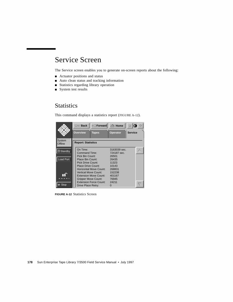
178 Sun Enterprise Tape Library 7/3500 Field Service Manual • July 1997
Service ScreenThe Service screen enables you to generate on-screen reports about the following:
■ Actuator positions and status■ Auto clean status and tracking information■ Statistics regarding library operation■ System test results
Statistics
This command displays a statistics report (FIGURE A-12).
FIGURE A-12 Statistics Screen
S
Load Port
Stop
Standby
HomeBack Forward
SystemOffline
TapesOverview Operator ServiceService
Report: Statistics
On Time:Command Time:Pick Bin Count:Place Bin Count:Pick Drive Count:Place Drive Count:Horizontal Move Count:Vertical Move Count:Extension Move Count:Gripper Move Count:Extension Force Count:Drive Place Retry:
3163039 sec.724187 sec.2650126435113231014326883115223840116776945242110
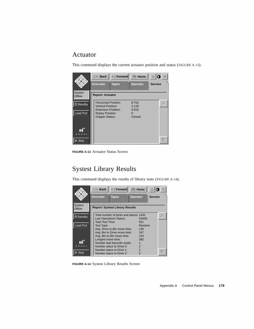
Appendix A Control Panel Menus 179
Actuator
This command displays the current actuator position and status (FIGURE A-13).
FIGURE A-13 Actuator Status Screen
Systest Library Results
This command displays the results of library tests (FIGURE A-14).
FIGURE A-14 Systest Library Results Screen
S
Load Port
Stop
Standby
HomeBack Forward
SystemOffline
TapesOverview Operator ServiceService
Report: Actuator
Horizontal Position:Vertical Position:Extension Position:Rotary Position:Gripper Status:
8.7523.1260.0150Closed
S
Load Port
Stop
Standby
HomeBack Forward
SystemOffline
TapesOverview Operator ServiceService
Report: Systest Library Results
Total number of picks and places:Last Operations Status:Total Test Time:Test Type:Avg. Drive to Bin move time:Avg. Bin to Drive move time:Avg. Bin to Bin move time:Longest move time:Number bad barcode reads:Number place to Drive 0:Number place to Drive 1:Number place to Drive 2:
143253A00501Random1461871343821222
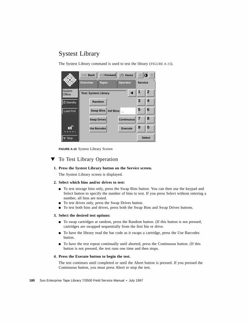
180 Sun Enterprise Tape Library 7/3500 Field Service Manual • July 1997
Systest Library
The Systest Library command is used to test the library (FIGURE A-15).
FIGURE A-15 Systest Library Screen
▼ To Test Library Operation
1. Press the Systest Library button on the Service screen.
The Systest Library screen is displayed.
2. Select which bins and/or drives to test:
■ To test storage bins only, press the Swap Bins button. You can then use the keypad andSelect button to specify the number of bins to test. If you press Select without entering anumber, all bins are tested.
■ To test drives only, press the Swap Drives button.■ To test both bins and drives, press both the Swap Bins and Swap Drives buttons.
3. Select the desired test options:
■ To swap cartridges at random, press the Random button. (If this button is not pressed,cartridges are swapped sequentially from the first bin or drive.
■ To have the library read the bar code as it swaps a cartridge, press the Use Barcodesbutton.
■ To have the test repeat continually until aborted, press the Continuous button. (If thisbutton is not pressed, the test runs one time and then stops.
4. Press the Execute button to begin the test.
The test continues until completed or until the Abort button is pressed. If you pressed theContinuous button, you must press Abort to stop the test.
S
Load Port
Stop
Standby
HomeBack Forward
SystemOffline
TapesOverview Operator ServiceService
Test: Systest Library
_
Random
Swap Bins
Swap Drives Continuous
ExecuteUse Barcodes
#of Bins:
1 2
3 4
5 6
7 8
9 0
Select
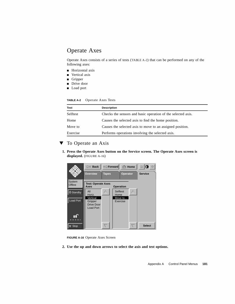
Appendix A Control Panel Menus 181
Operate Axes
Operate Axes consists of a series of tests (TABLE A-2) that can be performed on any of thefollowing axes:
■ Horizontal axis■ Vertical axis■ Gripper■ Drive door■ Load port
▼ To Operate an Axis
1. Press the Operate Axes button on the Service screen. The Operate Axes screen isdisplayed. (FIGURE A-16)
FIGURE A-16 Operate Axes Screen
2. Use the up and down arrows to select the axis and test options.
TABLE A-2 Operate Axes Tests
Test Description
Selftest Checks the sensors and basic operation of the selected axis.
Home Causes the selected axis to find the home position.
Move to Causes the selected axis to move to an assigned position.
Exercise Performs operations involving the selected axis.
S
Load Port
Stop
Standby
HomeBack Forward
SystemOffline
TapesOverview Operator ServiceService
Test: Operate AxesAxes Operation
AllHoriz.VerticalGripperDrive DoorLoad Port
SelftestHomeMove to...Exercise
Select
182 Sun Enterprise Tape Library 7/3500 Field Service Manual • July 1997
3. Press the Select button.
If you selected the Move To option, the Move To screen is displayed for you to specify thedestination of the move. Select an element type to move to and specify the position in inchesfrom home for the destination. Press Select to start the move.
Initialize Nonvol Statistics
This command purges NVRAM of all statistical information about library operation (theinformation reported with Statistics on the Service screen).
Initialize Nonvol Config
This command returns the library configuration to the factory defaults, negating any changesmade using Configure Library and Configure Options on the Operator screen.
Change Password
This command is used to change the operator password or service password. Passwords mustbe four to eight numbers in length.

183
APPENDIX B
Sense Data Values
TABLE B-1 lists message information that can be sent from the ETL 7/3500 library to
the host computer. The table lists the following information:
■ Sense key
■ Additional sense code (ASC)
■ Additional sense code qualifier (ASCQ)
■ Additional sense length (ASL) fields of the sense data block
■ Message name, description and (potential) recovery action
■ Valid interfaces:
■ SCSI (host computer)
■ Diag (diagnostic port/computer)
■ Both (SCSI and Diag)
Note – The message name and description may contain an abbreviation as follows:
LU = logical unit
REQ’D = required
DEV = device
Dia = diagnostics
NVRAM = nonvolatile RAM
A/D = analog-to-digital
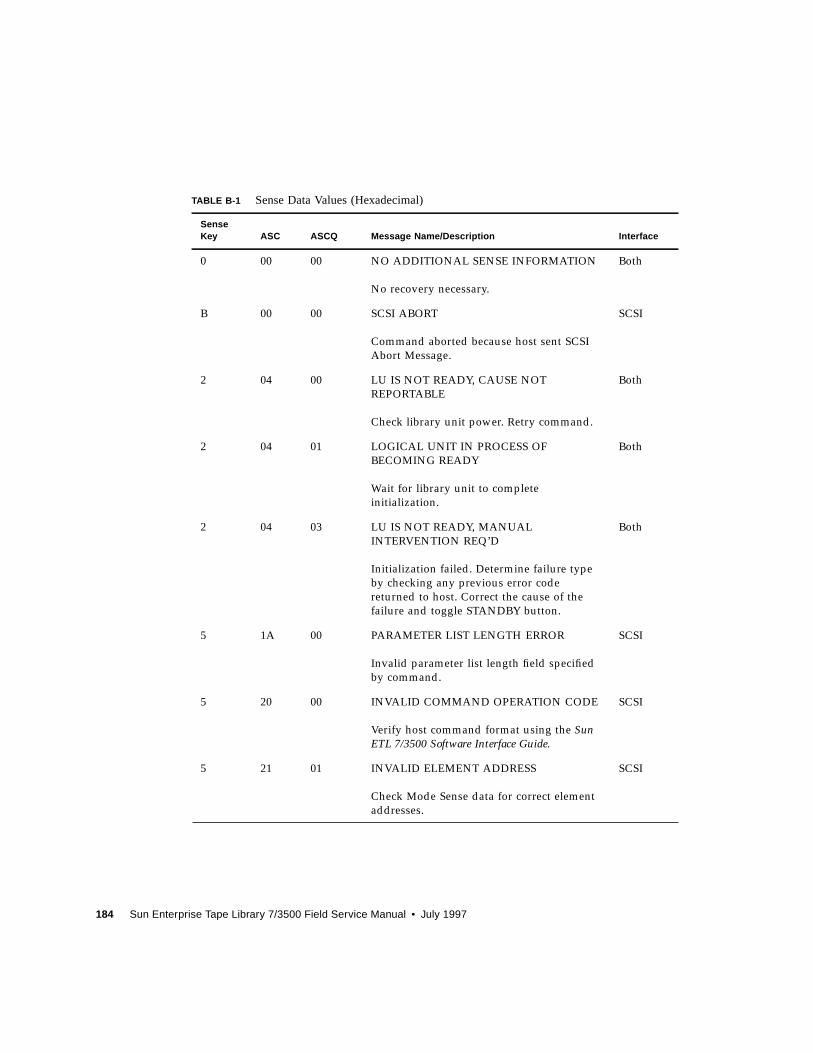
184 Sun Enterprise Tape Library 7/3500 Field Service Manual • July 1997
TABLE B-1 Sense Data Values (Hexadecimal)
SenseKey ASC ASCQ Message Name/Description Interface
0 00 00 NO ADDITIONAL SENSE INFORMATION
No recovery necessary.
Both
B 00 00 SCSI ABORT
Command aborted because host sent SCSI
Abort Message.
SCSI
2 04 00 LU IS NOT READY, CAUSE NOT
REPORTABLE
Check library unit power. Retry command.
Both
2 04 01 LOGICAL UNIT IN PROCESS OF
BECOMING READY
Wait for library unit to complete
initialization.
Both
2 04 03 LU IS NOT READY, MANUAL
INTERVENTION REQ’D
Initialization failed. Determine failure type
by checking any previous error code
returned to host. Correct the cause of the
failure and toggle STANDBY button.
Both
5 1A 00 PARAMETER LIST LENGTH ERROR
Invalid parameter list length field specified
by command.
SCSI
5 20 00 INVALID COMMAND OPERATION CODE
Verify host command format using the SunETL 7/3500 Software Interface Guide.
SCSI
5 21 01 INVALID ELEMENT ADDRESS
Check Mode Sense data for correct element
addresses.
SCSI
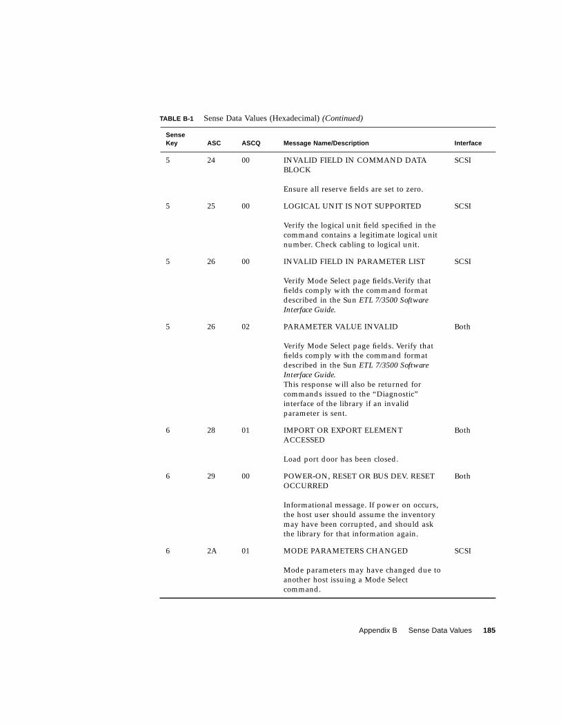
Appendix B Sense Data Values 185
5 24 00 INVALID FIELD IN COMMAND DATA
BLOCK
Ensure all reserve fields are set to zero.
SCSI
5 25 00 LOGICAL UNIT IS NOT SUPPORTED
Verify the logical unit field specified in the
command contains a legitimate logical unit
number. Check cabling to logical unit.
SCSI
5 26 00 INVALID FIELD IN PARAMETER LIST
Verify Mode Select page fields.Verify that
fields comply with the command format
described in the Sun ETL 7/3500 SoftwareInterface Guide.
SCSI
5 26 02 PARAMETER VALUE INVALID
Verify Mode Select page fields. Verify that
fields comply with the command format
described in the Sun ETL 7/3500 SoftwareInterface Guide.
This response will also be returned for
commands issued to the “Diagnostic”
interface of the library if an invalid
parameter is sent.
Both
6 28 01 IMPORT OR EXPORT ELEMENT
ACCESSED
Load port door has been closed.
Both
6 29 00 POWER-ON, RESET OR BUS DEV. RESET
OCCURRED
Informational message. If power on occurs,
the host user should assume the inventory
may have been corrupted, and should ask
the library for that information again.
Both
6 2A 01 MODE PARAMETERS CHANGED
Mode parameters may have changed due to
another host issuing a Mode Select
command.
SCSI
TABLE B-1 Sense Data Values (Hexadecimal)(Continued)
SenseKey ASC ASCQ Message Name/Description Interface
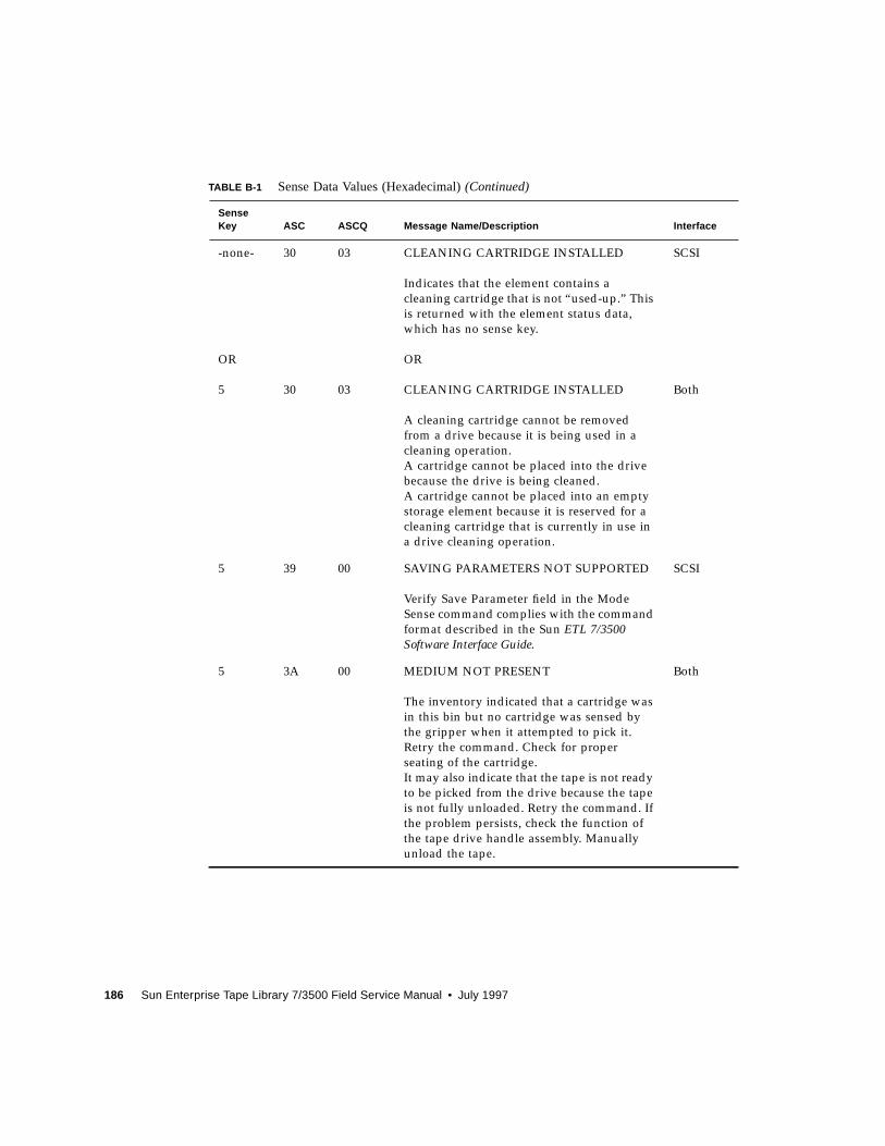
186 Sun Enterprise Tape Library 7/3500 Field Service Manual • July 1997
-none-
OR
5
30
30
03
03
CLEANING CARTRIDGE INSTALLED
Indicates that the element contains a
cleaning cartridge that is not “used-up.” This
is returned with the element status data,
which has no sense key.
OR
CLEANING CARTRIDGE INSTALLED
A cleaning cartridge cannot be removed
from a drive because it is being used in a
cleaning operation.
A cartridge cannot be placed into the drive
because the drive is being cleaned.
A cartridge cannot be placed into an empty
storage element because it is reserved for a
cleaning cartridge that is currently in use in
a drive cleaning operation.
SCSI
Both
5 39 00 SAVING PARAMETERS NOT SUPPORTED
Verify Save Parameter field in the Mode
Sense command complies with the command
format described in the Sun ETL 7/3500Software Interface Guide.
SCSI
5 3A 00 MEDIUM NOT PRESENT
The inventory indicated that a cartridge was
in this bin but no cartridge was sensed by
the gripper when it attempted to pick it.
Retry the command. Check for proper
seating of the cartridge.
It may also indicate that the tape is not ready
to be picked from the drive because the tape
is not fully unloaded. Retry the command. If
the problem persists, check the function of
the tape drive handle assembly. Manually
unload the tape.
Both
TABLE B-1 Sense Data Values (Hexadecimal)(Continued)
SenseKey ASC ASCQ Message Name/Description Interface
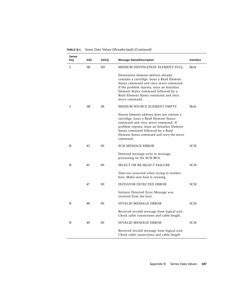
Appendix B Sense Data Values 187
5 3B 0D MEDIUM DESTINATION ELEMENT FULL
Destination element address already
contains a cartridge. Issue a Read Element
Status command and retry move command.
If the problem repeats, issue an Initialize
Element Status command followed by a
Read Element Status command and retry
move command.
Both
5 3B 0E MEDIUM SOURCE ELEMENT EMPTY
Source element address does not contain a
cartridge. Issue a Read Element Status
command and retry move command. If
problem repeats, issue an Initialize Element
Status command followed by a Read
Element Status command and retry the move
command.
Both
B 43 00 SCSI MESSAGE ERROR
Detected message error in message
processing on the SCSI BUS.
SCSI
B 45 00 SELECT OR RE-SELECT FAILURE
Time-out occurred when trying to reselect
host. Make sure host is running.
SCSI
47 00 INITIATOR DETECTED ERROR
Initiator Detected Error Message was
received from the host.
SCSI
B 48 00 INVALID MESSAGE ERROR
Received invalid message from logical unit.
Check cable connections and cable length.
SCSI
B 49 00 INVALID MESSAGE ERROR
Received invalid message from logical unit.
Check cable connections and cable length.
SCSI
TABLE B-1 Sense Data Values (Hexadecimal)(Continued)
SenseKey ASC ASCQ Message Name/Description Interface
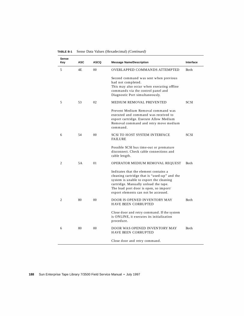
188 Sun Enterprise Tape Library 7/3500 Field Service Manual • July 1997
5 4E 00 OVERLAPPED COMMANDS ATTEMPTED
Second command was sent when previous
had not completed.
This may also occur when executing offline
commands via the control panel and
Diagnostic Port simultaneously.
Both
5 53 02 MEDIUM REMOVAL PREVENTED
Prevent Medium Removal command was
executed and command was received to
export cartridge. Execute Allow Medium
Removal command and retry move medium
command.
SCSI
6 54 00 SCSI TO HOST SYSTEM INTERFACE
FAILURE
Possible SCSI bus time-out or premature
disconnect. Check cable connections and
cable length.
SCSI
2 5A 01 OPERATOR MEDIUM REMOVAL REQUEST
Indicates that the element contains a
cleaning cartridge that is “used-up” and the
system is unable to export the cleaning
cartridge. Manually unload the tape.
The load port door is open, so import/
export elements can not be accessed.
Both
2 80 00 DOOR IS OPENED INVENTORY MAY
HAVE BEEN CORRUPTED
Close door and retry command. If the system
is ONLINE, it executes its initialization
procedure.
Both
6 80 00 DOOR WAS OPENED INVENTORY MAY
HAVE BEEN CORRUPTED
Close door and retry command.
Both
TABLE B-1 Sense Data Values (Hexadecimal)(Continued)
SenseKey ASC ASCQ Message Name/Description Interface
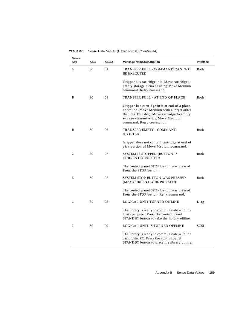
Appendix B Sense Data Values 189
5 80 01 TRANSFER FULL - COMMAND CAN NOT
BE EXECUTED
Gripper has cartridge in it. Move cartridge to
empty storage element using Move Medium
command. Retry command.
Both
B 80 01 TRANSFER FULL - AT END OF PLACE
Gripper has cartridge in it at end of a place
operation (Move Medium with a target other
than the Transfer). Move cartridge to empty
storage element using Move Medium
command. Retry command.
Both
B 80 06 TRANSFER EMPTY - COMMAND
ABORTED
Gripper does not contain cartridge at end of
pick portion of Move Medium command.
Both
2 80 07 SYSTEM IS STOPPED (BUTTON IS
CURRENTLY PUSHED)
The control panel STOP button was pressed.
Press the STOP button.
Both
6 80 07 SYSTEM STOP BUTTON WAS PRESSED
(MAY CURRENTLY BE PRESSED)
The control panel STOP button was pressed.
Press the STOP button. Retry command.
Both
6 80 08 LOGICAL UNIT TURNED ONLINE
The library is ready to communicate with the
host computer. Press the control panel
STANDBY button to take the library offline.
Diag
2 80 09 LOGICAL UNIT IS TURNED OFFLINE
The library is ready to communicate with the
diagnostic PC. Press the control panel
STANDBY button to place the library online.
SCSI
TABLE B-1 Sense Data Values (Hexadecimal)(Continued)
SenseKey ASC ASCQ Message Name/Description Interface
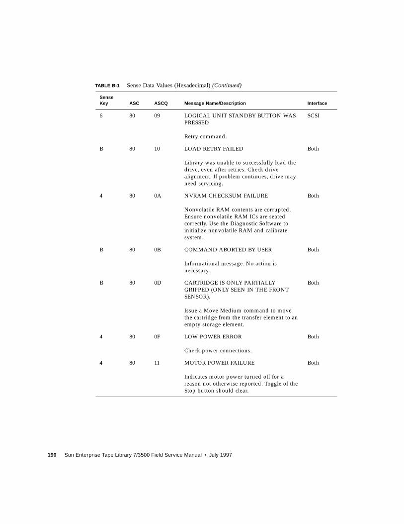
190 Sun Enterprise Tape Library 7/3500 Field Service Manual • July 1997
6 80 09 LOGICAL UNIT STANDBY BUTTON WAS
PRESSED
Retry command.
SCSI
B 80 10 LOAD RETRY FAILED
Library was unable to successfully load the
drive, even after retries. Check drive
alignment. If problem continues, drive may
need servicing.
Both
4 80 0A NVRAM CHECKSUM FAILURE
Nonvolatile RAM contents are corrupted.
Ensure nonvolatile RAM ICs are seated
correctly. Use the Diagnostic Software to
initialize nonvolatile RAM and calibrate
system.
Both
B 80 0B COMMAND ABORTED BY USER
Informational message. No action is
necessary.
Both
B 80 0D CARTRIDGE IS ONLY PARTIALLY
GRIPPED (ONLY SEEN IN THE FRONT
SENSOR).
Issue a Move Medium command to move
the cartridge from the transfer element to an
empty storage element.
Both
4 80 0F LOW POWER ERROR
Check power connections.
Both
4 80 11 MOTOR POWER FAILURE
Indicates motor power turned off for a
reason not otherwise reported. Toggle of the
Stop button should clear.
Both
TABLE B-1 Sense Data Values (Hexadecimal)(Continued)
SenseKey ASC ASCQ Message Name/Description Interface
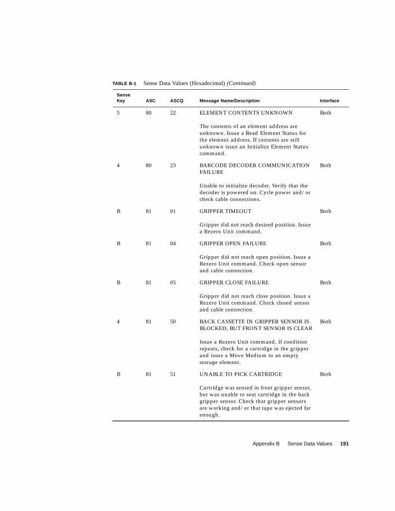
Appendix B Sense Data Values 191
5 80 22 ELEMENT CONTENTS UNKNOWN
The contents of an element address are
unknown. Issue a Read Element Status for
the element address. If contents are still
unknown issue an Initialize Element Status
command.
Both
4 80 23 BARCODE DECODER COMMUNICATION
FAILURE
Unable to initialize decoder. Verify that the
decoder is powered on. Cycle power and/or
check cable connections.
Both
B 81 01 GRIPPER TIMEOUT
Gripper did not reach desired position. Issue
a Rezero Unit command.
Both
B 81 04 GRIPPER OPEN FAILURE
Gripper did not reach open position. Issue a
Rezero Unit command. Check open sensor
and cable connection.
Both
B 81 05 GRIPPER CLOSE FAILURE
Gripper did not reach close position. Issue a
Rezero Unit command. Check closed sensor
and cable connection.
Both
4 81 50 BACK CASSETTE IN GRIPPER SENSOR IS
BLOCKED, BUT FRONT SENSOR IS CLEAR
Issue a Rezero Unit command. If condition
repeats, check for a cartridge in the gripper
and issue a Move Medium to an empty
storage element.
Both
B 81 51 UNABLE TO PICK CARTRIDGE
Cartridge was sensed in front gripper sensor,
but was unable to seat cartridge in the back
gripper sensor. Check that gripper sensors
are working and/or that tape was ejected far
enough.
Both
TABLE B-1 Sense Data Values (Hexadecimal)(Continued)
SenseKey ASC ASCQ Message Name/Description Interface
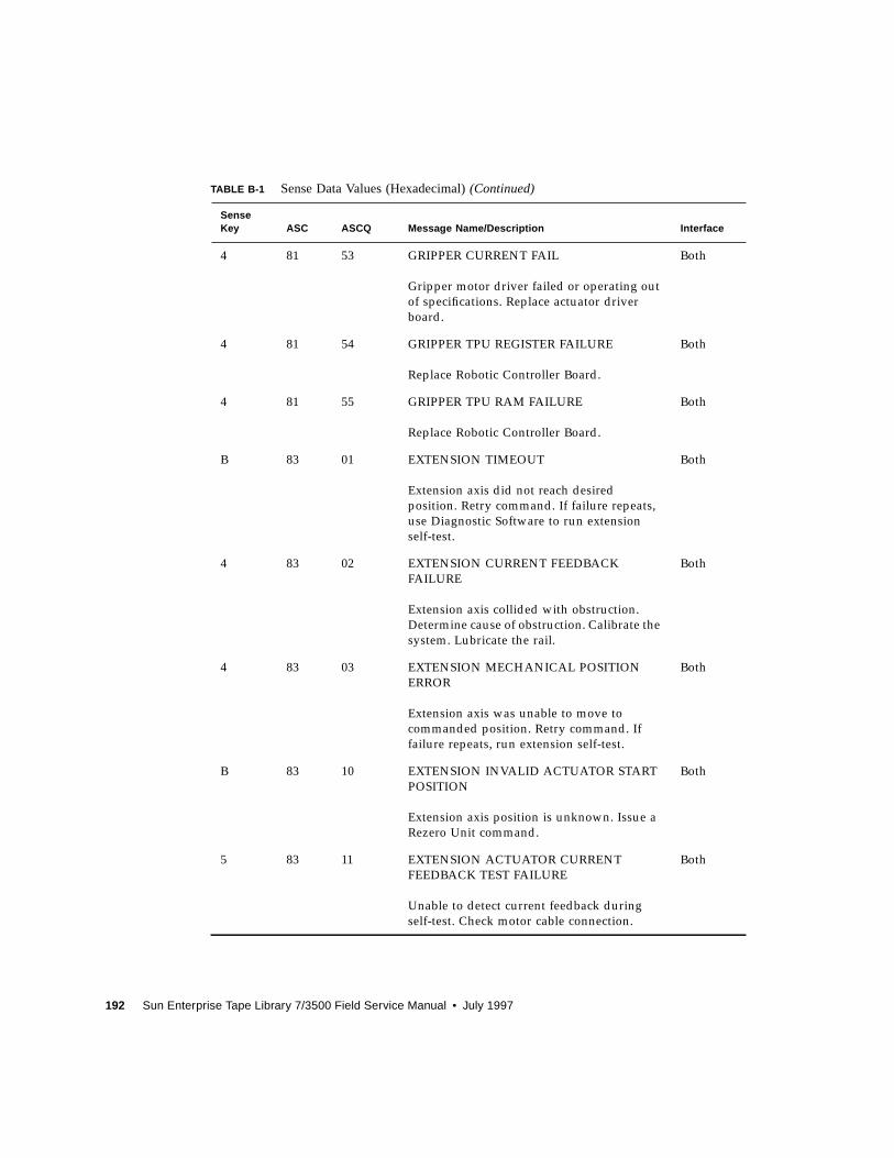
192 Sun Enterprise Tape Library 7/3500 Field Service Manual • July 1997
4 81 53 GRIPPER CURRENT FAIL
Gripper motor driver failed or operating out
of specifications. Replace actuator driver
board.
Both
4 81 54 GRIPPER TPU REGISTER FAILURE
Replace Robotic Controller Board.
Both
4 81 55 GRIPPER TPU RAM FAILURE
Replace Robotic Controller Board.
Both
B 83 01 EXTENSION TIMEOUT
Extension axis did not reach desired
position. Retry command. If failure repeats,
use Diagnostic Software to run extension
self-test.
Both
4 83 02 EXTENSION CURRENT FEEDBACK
FAILURE
Extension axis collided with obstruction.
Determine cause of obstruction. Calibrate the
system. Lubricate the rail.
Both
4 83 03 EXTENSION MECHANICAL POSITION
ERROR
Extension axis was unable to move to
commanded position. Retry command. If
failure repeats, run extension self-test.
Both
B 83 10 EXTENSION INVALID ACTUATOR START
POSITION
Extension axis position is unknown. Issue a
Rezero Unit command.
Both
5 83 11 EXTENSION ACTUATOR CURRENT
FEEDBACK TEST FAILURE
Unable to detect current feedback during
self-test. Check motor cable connection.
Both
TABLE B-1 Sense Data Values (Hexadecimal)(Continued)
SenseKey ASC ASCQ Message Name/Description Interface
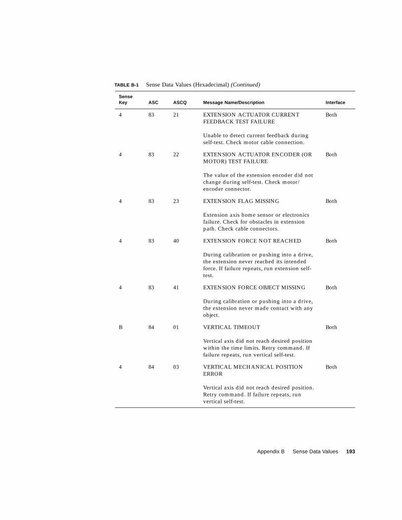
Appendix B Sense Data Values 193
4 83 21 EXTENSION ACTUATOR CURRENT
FEEDBACK TEST FAILURE
Unable to detect current feedback during
self-test. Check motor cable connection.
Both
4 83 22 EXTENSION ACTUATOR ENCODER (OR
MOTOR) TEST FAILURE
The value of the extension encoder did not
change during self-test. Check motor/
encoder connector.
Both
4 83 23 EXTENSION FLAG MISSING
Extension axis home sensor or electronics
failure. Check for obstacles in extension
path. Check cable connectors.
Both
4 83 40 EXTENSION FORCE NOT REACHED
During calibration or pushing into a drive,
the extension never reached its intended
force. If failure repeats, run extension self-
test.
Both
4 83 41 EXTENSION FORCE OBJECT MISSING
During calibration or pushing into a drive,
the extension never made contact with any
object.
Both
B 84 01 VERTICAL TIMEOUT
Vertical axis did not reach desired position
within the time limits. Retry command. If
failure repeats, run vertical self-test.
Both
4 84 03 VERTICAL MECHANICAL POSITION
ERROR
Vertical axis did not reach desired position.
Retry command. If failure repeats, run
vertical self-test.
Both
TABLE B-1 Sense Data Values (Hexadecimal)(Continued)
SenseKey ASC ASCQ Message Name/Description Interface
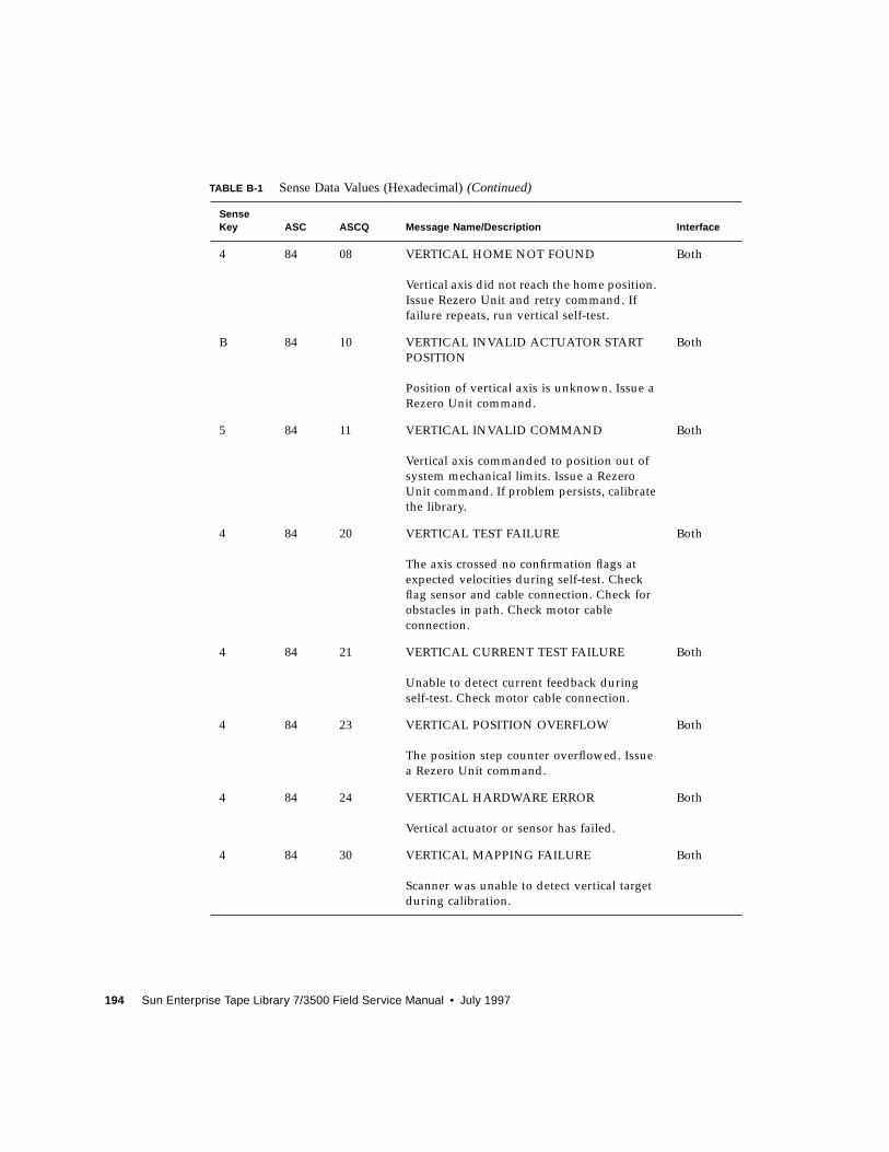
194 Sun Enterprise Tape Library 7/3500 Field Service Manual • July 1997
4 84 08 VERTICAL HOME NOT FOUND
Vertical axis did not reach the home position.
Issue Rezero Unit and retry command. If
failure repeats, run vertical self-test.
Both
B 84 10 VERTICAL INVALID ACTUATOR START
POSITION
Position of vertical axis is unknown. Issue a
Rezero Unit command.
Both
5 84 11 VERTICAL INVALID COMMAND
Vertical axis commanded to position out of
system mechanical limits. Issue a Rezero
Unit command. If problem persists, calibrate
the library.
Both
4 84 20 VERTICAL TEST FAILURE
The axis crossed no confirmation flags at
expected velocities during self-test. Check
flag sensor and cable connection. Check for
obstacles in path. Check motor cable
connection.
Both
4 84 21 VERTICAL CURRENT TEST FAILURE
Unable to detect current feedback during
self-test. Check motor cable connection.
Both
4 84 23 VERTICAL POSITION OVERFLOW
The position step counter overflowed. Issue
a Rezero Unit command.
Both
4 84 24 VERTICAL HARDWARE ERROR
Vertical actuator or sensor has failed.
Both
4 84 30 VERTICAL MAPPING FAILURE
Scanner was unable to detect vertical target
during calibration.
Both
TABLE B-1 Sense Data Values (Hexadecimal)(Continued)
SenseKey ASC ASCQ Message Name/Description Interface
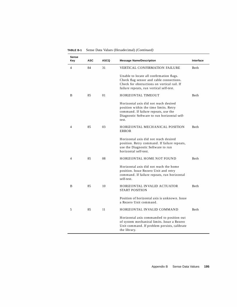
Appendix B Sense Data Values 195
4 84 31 VERTICAL CONFIRMATION FAILURE
Unable to locate all confirmation flags.
Check flag sensor and cable connections.
Check for obstructions on vertical rail. If
failure repeats, run vertical self-test.
Both
B 85 01 HORIZONTAL TIMEOUT
Horizontal axis did not reach desired
position within the time limits. Retry
command. If failure repeats, use the
Diagnostic Software to run horizontal self-
test.
Both
4 85 03 HORIZONTAL MECHANICAL POSITION
ERROR
Horizontal axis did not reach desired
position. Retry command. If failure repeats,
use the Diagnostic Software to run
horizontal self-test.
Both
4 85 08 HORIZONTAL HOME NOT FOUND
Horizontal axis did not reach the home
position. Issue Rezero Unit and retry
command. If failure repeats, run horizontal
self-test.
Both
B 85 10 HORIZONTAL INVALID ACTUATOR
START POSITION
Position of horizontal axis is unknown. Issue
a Rezero Unit command.
Both
5 85 11 HORIZONTAL INVALID COMMAND
Horizontal axis commanded to position out
of system mechanical limits. Issue a Rezero
Unit command. If problem persists, calibrate
the library.
Both
TABLE B-1 Sense Data Values (Hexadecimal)(Continued)
SenseKey ASC ASCQ Message Name/Description Interface
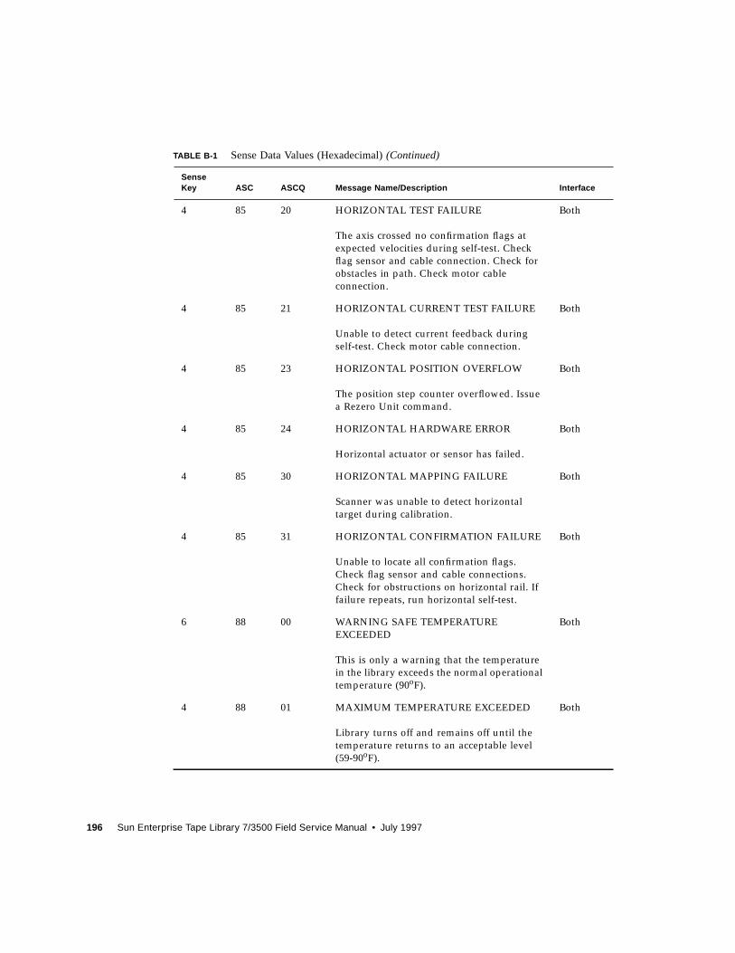
196 Sun Enterprise Tape Library 7/3500 Field Service Manual • July 1997
4 85 20 HORIZONTAL TEST FAILURE
The axis crossed no confirmation flags at
expected velocities during self-test. Check
flag sensor and cable connection. Check for
obstacles in path. Check motor cable
connection.
Both
4 85 21 HORIZONTAL CURRENT TEST FAILURE
Unable to detect current feedback during
self-test. Check motor cable connection.
Both
4 85 23 HORIZONTAL POSITION OVERFLOW
The position step counter overflowed. Issue
a Rezero Unit command.
Both
4 85 24 HORIZONTAL HARDWARE ERROR
Horizontal actuator or sensor has failed.
Both
4 85 30 HORIZONTAL MAPPING FAILURE
Scanner was unable to detect horizontal
target during calibration.
Both
4 85 31 HORIZONTAL CONFIRMATION FAILURE
Unable to locate all confirmation flags.
Check flag sensor and cable connections.
Check for obstructions on horizontal rail. If
failure repeats, run horizontal self-test.
Both
6 88 00 WARNING SAFE TEMPERATURE
EXCEEDED
This is only a warning that the temperature
in the library exceeds the normal operational
temperature (90oF).
Both
4 88 01 MAXIMUM TEMPERATURE EXCEEDED
Library turns off and remains off until the
temperature returns to an acceptable level
(59-90oF).
Both
TABLE B-1 Sense Data Values (Hexadecimal)(Continued)
SenseKey ASC ASCQ Message Name/Description Interface
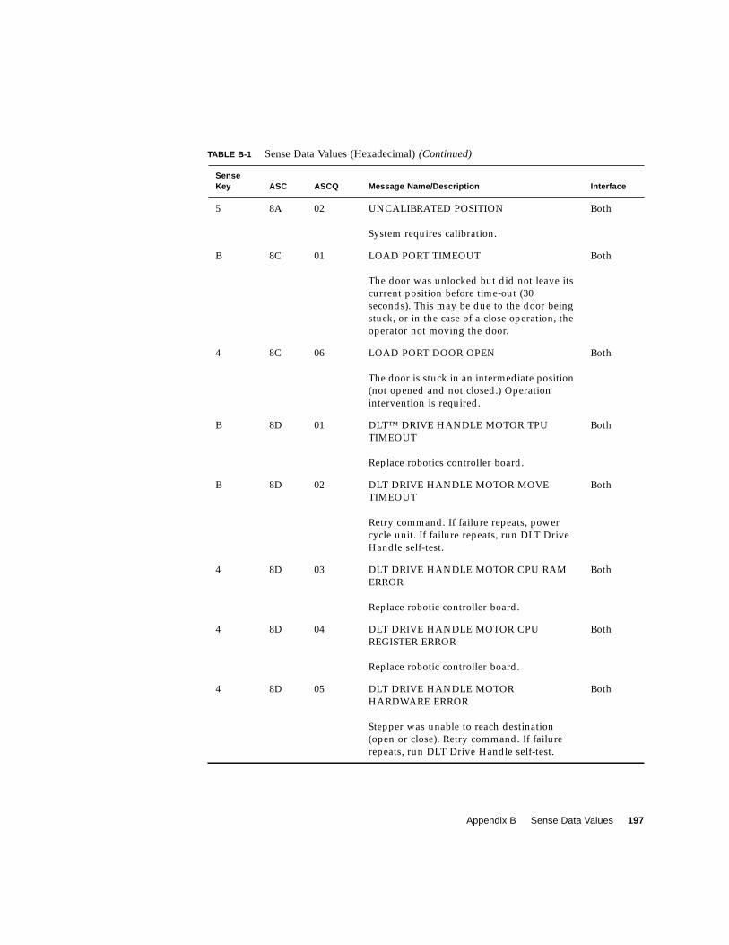
Appendix B Sense Data Values 197
5 8A 02 UNCALIBRATED POSITION
System requires calibration.
Both
B 8C 01 LOAD PORT TIMEOUT
The door was unlocked but did not leave its
current position before time-out (30
seconds). This may be due to the door being
stuck, or in the case of a close operation, the
operator not moving the door.
Both
4 8C 06 LOAD PORT DOOR OPEN
The door is stuck in an intermediate position
(not opened and not closed.) Operation
intervention is required.
Both
B 8D 01 DLT™ DRIVE HANDLE MOTOR TPU
TIMEOUT
Replace robotics controller board.
Both
B 8D 02 DLT DRIVE HANDLE MOTOR MOVE
TIMEOUT
Retry command. If failure repeats, power
cycle unit. If failure repeats, run DLT Drive
Handle self-test.
Both
4 8D 03 DLT DRIVE HANDLE MOTOR CPU RAM
ERROR
Replace robotic controller board.
Both
4 8D 04 DLT DRIVE HANDLE MOTOR CPU
REGISTER ERROR
Replace robotic controller board.
Both
4 8D 05 DLT DRIVE HANDLE MOTOR
HARDWARE ERROR
Stepper was unable to reach destination
(open or close). Retry command. If failure
repeats, run DLT Drive Handle self-test.
Both
TABLE B-1 Sense Data Values (Hexadecimal)(Continued)
SenseKey ASC ASCQ Message Name/Description Interface
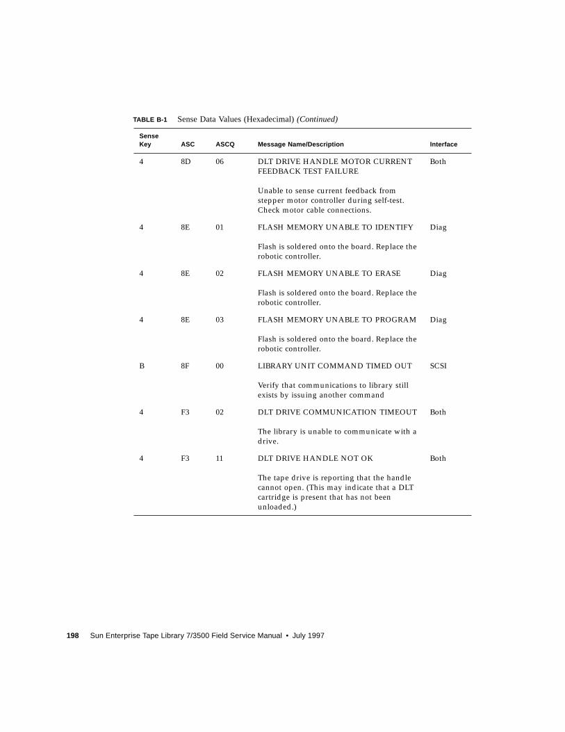
198 Sun Enterprise Tape Library 7/3500 Field Service Manual • July 1997
4 8D 06 DLT DRIVE HANDLE MOTOR CURRENT
FEEDBACK TEST FAILURE
Unable to sense current feedback from
stepper motor controller during self-test.
Check motor cable connections.
Both
4 8E 01 FLASH MEMORY UNABLE TO IDENTIFY
Flash is soldered onto the board. Replace the
robotic controller.
Diag
4 8E 02 FLASH MEMORY UNABLE TO ERASE
Flash is soldered onto the board. Replace the
robotic controller.
Diag
4 8E 03 FLASH MEMORY UNABLE TO PROGRAM
Flash is soldered onto the board. Replace the
robotic controller.
Diag
B 8F 00 LIBRARY UNIT COMMAND TIMED OUT
Verify that communications to library still
exists by issuing another command
SCSI
4 F3 02 DLT DRIVE COMMUNICATION TIMEOUT
The library is unable to communicate with a
drive.
Both
4 F3 11 DLT DRIVE HANDLE NOT OK
The tape drive is reporting that the handle
cannot open. (This may indicate that a DLT
cartridge is present that has not been
unloaded.)
Both
TABLE B-1 Sense Data Values (Hexadecimal)(Continued)
SenseKey ASC ASCQ Message Name/Description Interface
Glossary 1
Glossary
actuators Robotic components that move inside the library to manipulate cartridges.
These include the cartridge handling mechanism, extension axis, vertical and
horizontal axes.
automated tapelibrary A robotic storage and retrieval system for DLT tape cartridges.
bar code label The identification label on DLT tape cartridges.
bar code scanner A device that is mounted on the extension axis that reads the cartridge bar
code labels.
calibration The software measurements and configuration required for successful
operation of the library.
CHM Cartridge handling mechanism
DLT Digital linear tape
control panel A touch-screen panel on the front of the library that contains a main display
area as well as indicators and control buttons.
EIA/TIA-574 A serial communications cabling and protocol standard for nine pin
connectors, sometimes referred to as RS-232. The diagnostic port (DIAG), on the
rear of the library, uses this protocol.
extension axisassembly Mounted onto the vertical axis, the extension axis assembly consists of the
gripper assembly and the horizontal axis on which the gripper assembly is
mounted.
extension axis belt The drive belt connecting the extension motor/gearbox to the gripper.
FCC Class A Standard established by the U.S. Federal Communications Commission
governing electromagnetic emissions.
FSA Fixed storage array. This is a 4-column by 24-row fixture mounted inside the
library. Its purpose is to store up to 96 cartridges in the library.
2 Sun Enterprise Tape Library 7/3500 Field Service Manual • July 1997
FSE Field service engineer
gripper assembly The assembly that mounts on the extension axis and grips cartridges, referred
to as the CHM or gripper.
horizontal belt The drive belt connecting the horizontal motor to the horizontal axis assembly.
host Host computer
host computer The computer that issues SCSI commands to control the library robotics.
LCD Liquid crystal display
Load Port The operator accessible component of the library that allows up to four
cartridges to be import/export loaded and unloaded into/from the library.
MTBF Mean time between failures
MTTR Mean time to repair
NVRAM Nonvolatile RAM
offline Not ready for communications with a host. This mode is required for
configuration, diagnostic, and maintenance operations.
online Ready for communications with a host.
PC Personal computer
pick The act of removing a cartridge from one location in preparation for placing it
in another location.
place The act of placing a cartridge in a location after it has been picked from
another location.
PROM Programmable read-only memory
RAM Random access memory
rear panel The rear cosmetic panel of the library that contains the AC power switch, AC
power receptacle and connectors for attaching external cabling to the library.
SCSI Small computer system interface. A communications standard for attaching
peripheral equipment to computers.
tape drive The mechanism that reads and writes data from and to a tape cartridge.
UL Underwriters Laboratories
vertical belt The drive belt connecting the vertical motor to the vertical axis assembly.
vertical carriageassembly The crossbar and linear bearings mounted on the vertical rails and all
components mounted on the crossbar.

Glossary 3
ZIF connector Zero insertion force connector

4 Sun Enterprise Tape Library 7/3500 Field Service Manual • July 1997
Index 1
Index
Aactuator driver fuse isolation entry MAP, 68actuator driver PWA, 85actuator driver pwa, 6, 8, 9, 148adjustment, extension axis belt, 41alcohol, isopropyl, 27, 29, 30, 31applying library power, 160arrow buttons, 163auto calibrate
all, 105load port, 108procedure, 45
Bbar code
bar code scanner, 11bar code scanner pwa, 13bar code scanner pwa description, 13
belt
checking/adjusting extension axis, 41checking/adjusting x-axis, 37checking/adjusting y-axis tension, 35x-axis adjustment screw, 38x-axis clamp, 38y-axis adjustment screw, 35
y-axis clamp, 35block diagram
controller electronics assembly, 7extension axis assembly, 11library (simplified), 5
button
load port close, 17load port open, 17
Ccable
miscellaneous sensors, 159x-axis umbilical, 114y-axis umbilical, 112
calibrating
automatic calibration, 45calibration MAP, 66cartridge compatibility, 2CIG sensor, 11cleaning
cleaning procedures, 24extension axis, 29fan filter, 25rail, 26rollers, 31
2 Sun Enterprise Tape Library 7/3500 Field Service Manual • July 1997
tape drive, 30close button, 163configuration and statistics, 146control panel, 17, 163
buttons, 163debug MAP, 56
control panel assembly, 141controller electronics assembly, 145
block diagram, 7description, 6removing, 95
cosmetic panel
removing the left-side, 90removing the right-side, 93removing the top, 90replacing the left-side, 159replacing the right-side, 160replacing the top, 160
cosmetic panels
replacing, 159cover
removing the EMI, 93
Ddc fan assemblies, 126diagnostic PC, 7diagnostic software program (DSP), 146diagnostic test entry MAP, 53diagnostics initialization MAP, 60Digital Linear Tapes, 2down arrow button, 163
EEMI cover
removing, 93
Enterprise Tape Library 7/3500 Diagnostic
Software User’s Manual, xxixEnterprise Tape Library 7/3500 Facilities Planning
and Installation Guide, xxixEnterprise Tape Library 7/3500 Software Interface
Guide, xxixEnterprise Tape Library 7/3500 Unpacking
Instructions, xxixerror code
4800A (NVRAM checksum failure), 634800F (low power error), 55, 6348023 (bar code decoder communication
failure), 6548150 (rear cartridge-in-gripper sensor is
blocked, but front sensor is clear), 5548154 (gripper TPU register failure), 6248155 (gripper TPU RAM failure), 6248302 (extension current feedback failure), 6248303 (extension mechanical position error), 6248321 (extension actuator current feedback test
failure), 6248323 (extension flag missing), 6248340 (extension force not reached), 6248403 (vertical mechanical position error), 6448408 (horizontal home not found), 6448408 (vertical home not found), 6448421 (horizontal current test failure), 63, 7648421 (vertical current test failure), 62, 7448423 (horizontal position overflow), 63, 7548423 (vertical position overflow), 62, 7348424 (vertical sensor or actuator failed), 62,
73, 7448430 (vertical mapping failure), 6648431 (horizontal confirmation failure), 6448431 (vertical confirmation failure), 6448503 (horizontal mechanical position
error), 6448524 (horizontal sensor or actuator failed), 63,
75, 7648530 (horizontal mapping failure), 66

Index 3
48801 (maximum temperature exceeded), 5548C06 (load port door open), 5548D03 (tape drive handle TPU RAM
failure), 6248D04 (tape drive handle TPU register
failure), 6248D05 (tape drive handle motor hardware
error), 6348D06 (tape drive handle motor current
feedback test failure), 634F302 (tape drive communication timeout), 634F311 (tape drive handle not OK), 6358A02 (uncalibrated position), 6565400 (SCSI to host library interface failure), 5468800 (warning safe temperature exceeded), 55B4700 (SCSI parity error), 54B48153 (gripper current failure), 62B4900 (invalid message error), 54B8010 (load retry failed), 55B8101 (gripper timeout), 62B8104 (gripper open failure), 62B8105 (gripper close failure), 62B8151 (unable to pick cartridge), 55B8151(unable to pick cartridge), 55B8301 (extension timeout), 62B8401 (horizontal timeout), 63, 76B8401 (vertical timeout), 62, 74B8C01(load port timeout), 55B8D01 (tape drive handle TPU timeout), 62B8D02 (tape drive handle motor move
timeout), 63B8f00 (library unit command timed out), 54
error message entry MAP, 49error messages
see sense data values
ETL Servoce Kit, 24extension axis
assembly, 10assembly description, 10block diagram, 11
checking/adjusting belt, 41cleaning, 29drive motor and belt, 11drive motor and belt description, 11extension carriage interconnect pwa, 11extension carriage interconnect pwa
description, 11extension motor and encoder, 11extension motor and encoder description, 11extension platform, 10follower, 29gripper motor interface, 9gripper motor interface description, 9pulley idler, 43rail, 29rail lubrication, 44
extension axis assembly, 118, 126extension self-test failure MAP, 72
Ffan
filter, 21filter cleaning, 25physical location, 21
fans
dc, 126fault isolation entry MAP, 48fault LED, 84, 163filter
fan, 21filter, fan, 25firmware, 146Fixed Storage Array, 2
bin numbering, 2fixed storage array, 1force gauge, 35, 43front door interlock switch, 110
4 Sun Enterprise Tape Library 7/3500 Field Service Manual • July 1997
front door interlock switch description, 19front panel
replacing, 159FRU list, 98FRUs, 89
list of, 98fswitch
front door interlock switch in-line
connector, 159fuses
actuator driver PWA, 85robotic controller PWA, 84
Ggauge, force, 35, 43gripper
assembly, 10, 41cartridge-in-gripper (CIG) receiver pwa, 12cassette-in-gripper (CIG) receiver pwa, 12cassette-in-gripper (CIG) receiver pwa
description, 12cross shaft, 29gripper interconnect pwa, 12gripper interconnect pwa description, 12gripper motor, 12gripper motor description, 12sensor, 11
gripper self-test failure MAP, 71guidelines, preventive maintenance, 23
Hheatsink channel, 148home all MAP, 64horizontal self-test failure MAP, 75host interface failure MAP, 54
Iinventory MAP, 65
Kkit, preventive maintenance, 24
LLED
fault, 84, 163left-side panel
removing, 90replacing, 159
library
block diagram (simplified), 5description, 2
library operation failure MAP, 55load port
debug MAP, 56load port assembly description, 17lockout solenoid description, 20solenoid, 93switch 1 description, 19switch 2 description, 19switches, 94
logic power supply, 9, 87lubricating
extension axis rail, 44x-axis rail, 44y-axis rail, 44
Mmaintenance
preparing for, 89maintenance analysis procedures (MAPs)
actuator driver fuse isolation entry, 68calibration, 66
Index 5
control panel debug, 56diagnostic test entry, 53diagnostics initialization, 60error message entry, 49extension self-test failure, 72fault isolation entry, 48general instructions, 47gripper self-test failure, 71home all, 64horizontal self-test failure, 75host interface failure, 54inventory, 65library operation failure, 55load port debug, 56mechanical inspection entry, 50motor power interlock clearing, 58online initialization entry, 51online test entry, 52power entry, 61power supply evaluation entry, 69robotics controller fuse isolation entry, 67run diagnostics, 59self-test all, 62tape drive communication timeout, 78tape drive motor self-test failure, 77vertical self-test failure, 73, 74
mechanical inspection entry MAP, 50menu mode
SCSI address command, 169structure, 164
messages, system, see sense data values
miscellaneous sensors cable assembly, 159motor
extension and encoder, 11extension drive and belt, 11gripper, 12gripper interface, 9tape drive handle interface, 9
tape drive stepper, 128, 141x-axis, 15x-axis interface, 8x-axis stepper (m2) assembly, 102y-axis, 14y-axis interface, 8y-axis stepper assembly, 107
motor bus power supplies, 9motor power interlock clearing MAP, 58motor power supply assembly, 154mounting bracket
logic power supply, 151
Nnumbering of bins and tape drives, 2NVRAM, 145, 146
Ooffline, taking the library, 90online initialization entry, 51online test entry MAP, 52online, placing the library, 161open button, 163over voltage protector, 154
Ppanel
removing the front, 93removing the left-side, 90removing the right-side, 92removing the top, 90replacing the front, 159replacing the left-side, 159replacing the right-side, 160

6 Sun Enterprise Tape Library 7/3500 Field Service Manual • July 1997
top, 160physical location
actuator driver pwa, 6controller electronics assembly, 6extension axis assembly, 10fans, 21logic power supply, 6motor power supplies, 6robotics controller pwa, 6
placing the library online, 161potentiometer, 87power
applying to the library, 160logic power supply, 9logic power supply description, 9motor bus power supply, 9power supplies, 9power switch, 160removing from the library, 89
power entry MAP, 61power supply
logic, 87logic power supply physical location, 6motor power, 154motor power supply physical location, 6potentiometer, 87
power supply evaluation entry MAP, 69preparing for maintenance
removing cosmetic panels, 90removing library power, 89taking the library offline, 90
preventive maintenance
guidelines, 23kit, 24schedule, 23
procedure
auto calibrate, 45cleaning, 24
pulley idler, extension axis, 43PWA
actuator driver, 85robotic controller, 84tape drive interface, 86
pwa
actuator driver, 6, 8, 9, 148bar code scanner, 13cartridge-in-gripper (CIG) receiver, 12cassette-in-gripper (CIG) receiver, 12extension carriage interconnect, 11gripper interconnect, 12robotics controller, 6, 7, 145, 151tape drive interface, 20, 130, 132x-axis interconnect, 14, 99
Rrail
cleaning, 26lubricating, 44x-axis, 27x-axis lubrication, 44y-axis, 27y-axis lubrication, 44
remove/replace procedure
actuator driver pwa, 148, 150control panel assembly, 141, 142controller electronics assembly, 95dc fan (f1 & f2), 124, 125dc fan (f3 & f 4), 122dc fan (f3), 121dc fan (f4), 121dc fan assemblies, 126extension axis assembly, 126, 127front door interlock switch, 110, 111load port door lockout solenoid, 107, 109logic power supply, 153motor power supply assembly, 154, 156

Index 7
robotics controller pwa, 145, 147stepper motor assembly, 133, 141tape drive, 129tape drive distribution PWA, 137tape drive interface pwa, 130, 131tape drive MUX PWA, 140tape drive tray assembly, 135tape drives, 127x-axis interconnect pwa, 99, 101x-axis interruptive sensor, 143, 144x-axis stepper motor (m2) assembly, 102x-axis stepper motor assembly, 103x-axis umbilical cable, 114, 115y-axis drive belt, 126y-axis stepper motor assembly, 107y-axis umbilical cable, 112, 114
removing
cosmetic panels, 90EMI cover, 93front panel, 93, 95left-side panel, 90top panel, 90
replacing
cosmetic panels, 159front panel, 95, 159
retention tabs, 90, 91right-side panel
removing, 92replacing, 160
robotic controller PWA, 84robotic controller pwa, 11robotics controller fuse isolation entry MAP, 67robotics controller pwa, 6, 7, 145, 151robotics controller pwa, description, 7rollers
checking/adjusting x-axis, 33checking/adjusting y-axis, 34cleaning, 31
x-axis, 31y-axis, 31
RS-232, 7run diagnostics MAP, 59
Sschedule, preventive maintenance, 23SCSI address
library, 169SCSI II, 7, 20SCSI interface, 2select button, 163self-test all MAP, 62sense data values, 183sensor
CIG, 11gripper, 11miscellaneous sensors cable assembly, 159x-axis confirmation, 14x-axis interruptive, 143y-axis, 11y-axis confirmation, 13
shunt OVP, 8description, 8
solenoid
load port, 93load port door lockout, 107load port lockout, 20load port lockout interface, 9load port solenoid in-line connector, 159
standby button, 163status display area (SDA), 89, 163stepper motor assembly, 128, 141stop button, 163switch
front door interlock, 19, 110

8 Sun Enterprise Tape Library 7/3500 Field Service Manual • July 1997
load port, 94load port limit, 20load port switch 1, 19load port switch 2, 19power, 160
system messages, see sense data values
Ttab
retention, 90, 91tape drive, 127, 128, 130, 132
cleaning, 30compatibility, 2handle drive assemblies description, 20interface pwa, 130receiver, 30status/control panel, 20stepper motor assembly, 128tape drive description, 20tape drive handel motor interface, 9tape drive handle motor interface, 9tape drive interface pwa description, 20
tape drive communication timeout MAP, 78tape drive interface PWA, 86tape drive interface pwa, 132tape drive motor self-test failure MAP, 77test points, voltage, 84top panel, 160troubleshooting
see also maintenance analysis procedures
Uup arrow button, 163
Vvertical self-test failure MAP, 73, 74voltage
+12V, 8+24 VDC, 8, 9, 11+48 VDC, 8, 9+5V, 8115 VAC, 9230 VAC, 9
voltage test points
actuator driver PWA, 85robotic controller PWA, 84
Xx-axis
checking/adjusting belt, 37checking/adjusting rollers, 33interruptive sensor, 143rail, 27rail lubrication, 44removing the interconnect pwa, 99removing the stepper motor assembly, 102rollers, 31umbilical cable, 114x-axis confirmation sensor, 14x-axis confirmation sensor description, 14x-axis interconnect pwa, 14x-axis interconnect pwa description, 14x-axis motor, 15x-axis motor interface, 8x-axis motor interface description, 8
x-carriage
x-carriage assembly description, 13x-carriage description, 14
Yy-axis
Index 9
checking/adjusting belt tension, 35checking/adjusting rollers, 34confirmation sensor, 13confirmation sensor description, 13rail, 27rail lubrication, 44removing the stepper motor assembly, 107rollers, 31sensor, 11umbilical cable, 112y-axis motor description, 14y-axis motor interface, 8y-axis motor interface description, 8

10 Sun Enterprise Tape Library 7/3500 Field Service Manual • July 1997
Related Documents