102 10-Year Transmission Assessment Summary • Need categories (definitions of project need drivers) • Planned, proposed and conceptual projects (tables showing projects by year, by project type and by zone) • Estimated capital costs of projects Summary of Planned, Proposed and Conceptual Additions, 2003-2012 The facilities proposed by the ATC based on this 2003 Assessment are listed in Tables VI-1 through VI-19, and shown graphically by zone in Figures VI-1 through VI-5. In addition, alternatives for some the primary alternatives shown in Tables VI-1 through VI-19 are listed in Table VI-20. Also, portions of the plan in the 2002 Update Assessment that are not included in this plan are listed in Table VI-21. In each of these tables, there is a column indicating the planned in service year for each particular facility and a column indicating the year the facility is needed. There are numerous facilities for which the year it is needed precedes the planned in service year. There are a variety of reasons for this, including: • The preferred alternative to address a particular need may take several years to implement. • The need may have existed but had been addressed with operating procedures that are becoming less effective or ineffective. • The preferred alternative to address a particular need may need to be implemented in phases, thus delaying certain phases. • New data or information became available that affected the nature of the need or limitation, which necessitated a change in the alternative to be implemented, introducing a delay in implementation. • The need for a project was based on load or generation development that was uncertain. • Stakeholder input necessitated a change in the alternative to be implemented, introducing a delay in implementation. Tables VI-1 through VI-10 show the facilities planned by year for 2003-2012 respectively. Tables VI-11 through VI-15 show the facilities planned by zone. Table V-16 provides a list of planned transmission lines involving new right-of-way for 2004-2012. Since ATC intends to solicit public input on the identification of ultimate solutions through its iterative planning process, these particular projects may be modified in the future. Table V-17 provides a list of proposed transmission line rebuilds, reconductoring and uprates on existing right-of-way. Table V-18 provides a list of proposed new substations and transformer additions (excluding transmission-to- distribution transformers). Table V-19 provides a list of other proposed substation equipment additions or replacements. Need Categories Within the above tables, the need for each project is identified. Need categories include the following: Reliability: Facility (line, transformer, substation equipment) normal rating is exceeded under normal system conditions or emergency rating is exceeded under single contingency conditions, or bus voltage is not within 5% of nominal voltage under normal system conditions or is not within 10% of nominal voltage under single contingency conditions. (see Appendix C) Impending overload or voltage violations are noted as appropriate. New generation: Facility has been identified as necessary to accommodate new generation in generation interconnection studies and related transmission service studies conducted by ATC. TLR: Facility has been identified by ATC Operations or ATC Transmission Service as a chronic cause for interrupting, curtailing, limiting or denying transmission service in real time. T-D interconnection: Facility is required to interconnect to a new transmission-distribution substation needed by a distribution company served by ATC. Condition: Facility has been identified by ATC Maintenance as being in need of repair or replacement. Stability: Facility has been identified by ATC Stability and Special Studies as needed to ensure ATC dynamic stability criteria is met (see Appendix C), or will improve stability response of generation. Import capability: Facility will enhance import capability of the ATC transmission system. section 6 Summary of Planned and Proposed Facility Additions in the 2003 Assessment

Welcome message from author
This document is posted to help you gain knowledge. Please leave a comment to let me know what you think about it! Share it to your friends and learn new things together.
Transcript

102
10-Year Transmission Assessment
Summary• Need categories (definitions of project need drivers)• Planned, proposed and conceptual projects (tables showing projects
by year, by project type and by zone)• Estimated capital costs of projects
Summary of Planned, Proposed and Conceptual Additions, 2003-2012
The facilities proposed by the ATC based on this 2003 Assessment arelisted in Tables VI-1 through VI-19, and shown graphically by zone inFigures VI-1 through VI-5. In addition, alternatives for some theprimary alternatives shown in Tables VI-1 through VI-19 are listed inTable VI-20. Also, portions of the plan in the 2002 Update Assessmentthat are not included in this plan are listed in Table VI-21.
In each of these tables, there is a column indicating the planned inservice year for each particular facility and a column indicating theyear the facility is needed. There are numerous facilities for which theyear it is needed precedes the planned in service year. There are avariety of reasons for this, including:• The preferred alternative to address a particular need may take
several years to implement.• The need may have existed but had been addressed with
operating procedures that are becoming less effective orineffective.
• The preferred alternative to address a particular need may needto be implemented in phases, thus delaying certain phases.
• New data or information became available that affected thenature of the need or limitation, which necessitated a change inthe alternative to be implemented, introducing a delay inimplementation.
• The need for a project was based on load or generationdevelopment that was uncertain.
• Stakeholder input necessitated a change in the alternative to beimplemented, introducing a delay in implementation.
Tables VI-1 through VI-10 show the facilities planned by year for2003-2012 respectively. Tables VI-11 through VI-15 show thefacilities planned by zone. Table V-16 provides a list of plannedtransmission lines involving new right-of-way for 2004-2012. SinceATC intends to solicit public input on the identification of ultimatesolutions through its iterative planning process, these particularprojects may be modified in the future. Table V-17 provides a list ofproposed transmission line rebuilds, reconductoring and uprates onexisting right-of-way. Table V-18 provides a list of proposed newsubstations and transformer additions (excluding transmission-to-distribution transformers). Table V-19 provides a list of otherproposed substation equipment additions or replacements.
Need CategoriesWithin the above tables, the need for each project is identified. Needcategories include the following:
Reliability: Facility (line, transformer, substationequipment) normal rating is exceededunder normal system conditions oremergency rating is exceeded under singlecontingency conditions, or bus voltage isnot within 5% of nominal voltage undernormal system conditions or is not within10% of nominal voltage under singlecontingency conditions. (see Appendix C)Impending overload or voltage violationsare noted as appropriate.
New generation: Facility has been identified as necessary toaccommodate new generation in generationinterconnection studies and relatedtransmission service studies conducted byATC.
TLR: Facility has been identified by ATCOperations or ATC Transmission Service asa chronic cause for interrupting, curtailing,limiting or denying transmission service inreal time.
T-D interconnection: Facility is required to interconnect to a newtransmission-distribution substationneeded by a distribution company servedby ATC.
Condition: Facility has been identified by ATCMaintenance as being in need of repair orreplacement.
Stability: Facility has been identified by ATC Stabilityand Special Studies as needed to ensureATC dynamic stability criteria is met (seeAppendix C), or will improve stabilityresponse of generation.
Import capability: Facility will enhance import capability ofthe ATC transmission system.
section6Summary of Planned and Proposed FacilityAdditions in the 2003 Assessment

10-Year Transmission Assessm
ent 103
WAUSAU
SIGEL
ARPIN
BADGER
WIEN SS
METOMEN
MCKENNA
LINCOLN
COYNE SS
CAROLINE
SKANAWAN
OHMSTEAD
WHITCOMB
ROCKY RUN
SAND LAKE
PETENWELL
IRON RIVER
BLACKBROOK
GREEN LAKE
FITZGERALD
BUNKER HILL
CASTLE ROCK
CHAFFEE CREEK
NORTH RANDOLPH
DEWEY (ALTE/CWEC)
WEST WISCONSIN RAPIDS
IOLA
PINE
HUME
VENUS
HINTZ
HODAG
KELLY
TAYCO
RIPON
EASTOM
ARNOTT
WAUPUN
HOOVER
ROEDER
PLOVER
CASSEL
BERLIN
HILLTOP
HANCOCK
CONOVER
OSHKOSH
PORTAGE
ROSHOLT
HILLTOP
WAUTOMA
GOODMAN
WAUPACA
TRIENDA
BOWEN ST
SARATOGA
WILDWOOD
HARRISON
CASALOMA
AVIATIONPROGRESS
MOUNTAIN
MCMILLAN
STRATFORD
REEDSBURG
TWIN LAKE
BUTTERNUT
HIGHWAY 8
LAWN ROAD
CRANBERRY
PEARL AVE
AURORA ST
ELLINGTON
WOODENSHOE
WHITE LAKE
WHITE CLAY
DEER TRAIL
SHERMAN ST
CLEAR LAKE
NORTHPOINT
WINNECONNE
CITY LIMITS
THREE LAKES
WHITING AVE
SUMMIT LAKE
ST. GERMAIN
GOLDEN SANDS
SUNSET POINT
EAST SHAWANO
WEST SHAWANO
PORT EDWARDS
SILVER CLIFF
CLINTONVILLE
CRYSTAL FALLS
COUNCIL CREEK
BUTTE DES MORTES
NORTH FOND DU LAC
SEI
WESTON
KILBOURN
WEYAUWEGA HYDRO
PETENWELL HYDRO
CASTLE ROCK HYDRO
SOUTH FOND DU LAC
P r i c e
C l a r k
O n e i d a
M a r a t h o n
F o r e s t
V i l a s
T a y l o r
W o o d
M o n r o e
L i n c o l n
J u n e a u
A d a m s
P o r t a g e
L a n g l a d e
S h a w a n o
W a u p a c a
J a c k s o n
R u s k
W a u s h a r a
S a w y e r
V e r n o n
O c o n t o
W i n n e b a g o
I r o n
S a u k
M a r q u e t t e
A s h l a n d
O u t a g a m i e
D o d g e
F o n d d u L a c
F l o r e n c e
G r e e n L a k e
M e n o m i n e e
C o l u m b i a
M a r i n e t t e
R i c h l a n d
Zone1 11x17.mxd Modified: May 20, 2003
P L A N N I N G Z O N E 1E l e c t r i c T r a n s m i s s i o n N e t w o r k & S u b s t a t i o n s
"
"
0 10 205 Miles
M I C H I G A N
W I S C O N S I N
ZONE2
ZONE1
ZONE3
ZONE4
ZONE5
Currently, ATC owns or operates transmission facilities in 50 Wisconsin countiesand in 15 Michigan counties. Facilities include: * Approximately 8900 miles of transmission lines * 98 wholly owned substations * 358 jointly owned substations * Offices in Madison (2), Cottage Grove, Pewaukee, De Pere Wausau and Kingsford, MI
KEY
New Substation
Phase Shifter
Transformer
345 kV Transmission Line
115 or 138 kV Transmission Line
Substation Modifications
Rebuilt 115 or 138 kV Transmission Line
SS
Capacitor Bank
New T-D Interconnection
C
T
SM
PS
T-D
Transmission Line Voltage Conversion
69 kV Transmission Line
T-D
T
Fitzgerald
T-D
SMC
PS
CC
Omro
Weston
SMT
C
C SMT
SM
SM
PINE
C
SM
C
SM
SM
T-D
CRANBERRY T
T
LincolnTo
Arrowhead
HIGHWAY 8
SM
SM
SM
T-D T-D
T-D
T-D
SM
SM
C
Antigo
C
CSM C
TWood
T
SM
Maine
SM
SM
Wis Rapids
0 10 205 Miles
ATC Office Location!.
"
"!(
#*
Proposed/Design/Construction
Joint Owned Substation - Assets Conveyed Generation
ATC Owned Substation
Other Facility
Transmission Related FacilitiesCurrently, ATC owns or operates transmission facilities in 50 Wisconsin countiesand in 15 Michigan counties. Facilities include: * Approximately 8900 miles of transmission lines * 98 wholly owned substations * 358 jointly owned substations * Offices in Madison (2), Cottage Grove, Pewaukee, De Pere Wausau and Kingsford, MI
Joint Owned Substation - Assets Retained
WV
0 10 205 MilesE l e c t r i c T r a n s m i s s i o n N e t w o r k & S u b s t a t i o n s
P L A N N I N G Z O N E 1
Figure VI-1Zone 1 Transmission System Additions
May be Planned, Proposed or Conceptual
Merrill
Tomahawk
Rhinelander
Eagle River
Stevens Pt
Tomah
T-D
Transmission Related Facilities
Other Facility
ATC Owned Substation
GenerationJoint Owned Substation - Assets Conveyed
Joint Owned Substation - Assets RetainedProposed/Design/Construction
������
���
�
�� ATC Office Location

10-Year Transmission Assessment
104
L a k e S u p e r i o r
L a k e H u r o n
L a k e M i c h i g a n
C A N A D A
M I C H I G A N
KINGSFORD
CEDAR
AMBERG
ARNOLD
NORDIC
EMPIRE
PERKINS
FORSYTH
ROSEBUSH
HIAWATHA
CHANDLER
NATIONAL
MCGULPIN
NINE MILE
IRON RIVER
DEAD RIVER
PINE RIVER
PERCH LAKE
BLANEY PARK
WHITE RAPIDS
FOX HILLS SS
POINT LEBARBE
REPUBLIC--STATE FOREST
Negaunee
Escanaba
Marquette
Norway
Sault Ste. Marie
Ishpeming
Gwinn
Munising
Iron MountainGladstone
Kingsford
K. I. Sawyer AFB
L'Anse
Iron River
Ontonagon
Houghton
Baraga
Manistique
Chatham
Harvey
Crystal Falls
St. Ignace
Hubbell
Mackinac Island
De Tour Village
Gaastra
Hancock
Caspian
Alpha
Carney
Daggett
Powers
Garden
Mineral Hills
Newberry
Stephenson
Laurium
Lake Linden
South Range
AhmeekCopper City
Crandon
Rhinelander
Niagara
Eagle River
Wausaukee
MASS
M-38
VENUS
DELTA
FELCH
HODAG
GWINN
WINONA
POWERS
REXTON
ARAGON
CURTIS
TILDEN
SAGOLACONOVER
CORNELL
BREVORT
PORTAGE
OSCEOLA
GOODMAN
ATLANTIC
MUNISING
VICTORIA
TWIN LAKE
HIGHWAY 8
ONTONAGON
CRANBERRY
TALENTINO
THREE MILE
MANISTIQUE
TROUT LAKE
MASONVILLE
PEAVY FALLS
THREE LAKES
SUMMIT LAKE
ST. GERMAIN
DAVES FALLS
INDIAN LAKE
CHALK HILLS
LOADING DOCK
LAND O LAKES
SILVER CLIFF
GRAND RAPIDS
CRYSTAL FALLS
CALDRON FALLS
PORTAGE STREET
WATERSMEET NEW
ROBERTS CORNER
BRUCE CROSSING
QUINESSEC FALLS
UPPCO
WAY PLANT
TWIN FALLS
PINE PLANT
BRULE PLANT
HEMLOCK FALLS
PRESQUE ISLE POWER PLANT
M I C H I G A N
W I S C O N S I N
ZONE2
ZONE1
ZONE3
ZONE4
ZONE5
0 10 20 30 405Miles
Zone2 11x17.mxd Modified: May 28, 2003
Transmission Related FacilitiesP L A N N I N G Z O N E 2
E l e c t r i c T r a n s m i s s i o n N e t w o r k & S u b s t a t i o n s
Other Facility
ATC Owned Substation
GenerationJoint Owned Substation - Assets ConveyedJoint Owned Substation - Assets RetainedProposed/Design/Construction
#*$+
!( WV""
!. ATC Office Location
Currently, ATC owns or operates transmission facilities in 50 Wisconsin counties and in 15 Michigan counties.Facilities include: * Approximately 8900 miles of transmission lines * 98 wholly owned substations * 358 jointly owned substations * ATC offices in Madison (2), Cottage Grove, Pewaukee, De Pere, Wausau and Kingsford, MI
Figure VI-2Zone 2 Transmission System Additions
May be Planned, Proposed or ConceptualKEY
New Substation
Transformer
345 kV Transmission Line
115 or 138 kV Transmission Line
Substation Modifications
Rebuilt 115 or 138 kV Transmission
SS
Capacitor Bank
New T-D Interconnection
C
T
SM
T-D
Transmission Line Voltage Conversion
69 kV Transmission Line
Elevation
GlenJenks
SM
Engadine
Plains
T StraitsRandville
Powers Harris
Escanaba
T
T-D T-D
CrandonLaona
CT
Iron River
HiawathaRexton
T
SM
SM
Munising
Marquette
Ishpeming
Gladstone
EagleRiver
CrystalFalls
Newberry
DeTour
TWINLAKE
Transmission Related Facilities
Other Facility
ATC Owned Substation
GenerationJoint Owned Substation - Assets ConveyedJoint Owned Substation - Assets RetainedProposed/Design/Construction
������ ��
��
�� ATC Office Location

10-Year Transmission Assessment
105
I L L I N O I S
I O W A
FEN OAK
COTTAGE GROVE
COONEY
MINERS
HILLMAN
KEGONSA
ELKHORN
ACADEMY
PADDOCK
COLUMBUS HARTFORD
CRAWFISH
KIRKWOOD
WAUNAKEE
BRODHEAD
ROCKDALE
GRAN GRAE
UNIVERSITY
STAGECOACH
BASS CREEK
JENNINGS RD
REINER ROAD
ROCK BRANCH
NORTH MONROE
NORTH MADISON
NORTH RANDOLPH
Madison
Fitchburg
Janesville
Beloit
Delafield
Portage
Waukesha
Pewaukee
Elkhorn
Sun Prairie
Delavan
Steuben
Middleton
Watertown
Hartford
Baraboo
Waunakee
Monroe
Lake Delton
Wauzeka
Beaver Dam
HartlandOconomowoc
Burlington
Jefferson
De Forest
Reedsburg
Bell Center
Slinger
Milton
Chenequa
Lake Geneva
Whitewater
Verona
Horicon
Waterloo
Gays Mills
Eastman
Platteville
Monona
Oregon Stoughton
Viroqua
Wales
Prairie du Chien
Columbus
Mukwonago
Fort Atkinson
East Troy
Avoca
Merton
Twin Lakes
Edgerton
Lake Mills
Rio
Mayville
Doylestown
Dodgeville
McFarland
Lodi
Lancaster
Poynette
Richland Center
Waupun
Potosi
Lomira
Westby
Boscobel
Williams Bay
Ferryville
Soldiers Grove
Eagle
Juneau
Dane
Mount Horeb
Mineral Point
Evansville
Pardeeville
North Prairie
Marshall
Darien
Genoa City
Arena
Albany
Nashotah
Clinton
Brodhead
Cobb
Oconomowoc Lake
Wyocena
Sauk City
Readstown
Fox Lake
Fontana-on-Geneva Lake
Cottage Grove
Palmyra
Fall River
Walworth
Johnson Creek
Lowell
Merrimac
Lynxville
Plain
Wisconsin Dells
Sullivan DousmanBarneveld
Hillsboro
Fennimore
Sharon
De Soto
Cambria
Ridgeway
Belleville
DeerfieldHighland
New Glarus
Mazomanie
Viola
La Farge
Benton
Bagley
Friesland
Footville
Linden
Lone Rock
Monticello
Orfordville
Muscoda
Shullsburg
Prairie du Sac
Wonewoc
Rock Springs
Sussex
Darlington
Spring Green
Theresa
Hazel Green
Cross Plains
Cuba City
Cassville
Mount Sterling
Bloomington
Hustisford
Cazenovia
Browntown
Argyle
Randolph
Lime Ridge
Neosho
Gratiot
Campbellsport
Livingston
Dickeyville
Rewey
Kewaskum
BoazArlington
Blue River
Belmont
Iron Ridge
Hollandale
Cambridge
South Wayne
Brooklyn
Reeseville
West BarabooNorth Freedom
Montfort
Black Earth
Blue Mounds
Yuba
Maple Bluff
Lac La Belle
La Valle
Shorewood Hills
Chaseburg
Ironton
Tennyson
Brownsville
Patch Grove
Clyman
West Bend
RockdaleMount Hope
Kekoskee
Blanchardville
Woodman
Loganville
RIO
SHAW
DANE
EDEN
MCCUE
TRIPP
SOUTH
WINGRA
TURTLE
OREGON
WAUPUN
YAHARA
SUMMIT
AUBURN
RUSKIN
VERONA
GATEWAY
SUNRISE
PORTAGE
RUSSELL
HORICON
BRISTOL
CONCORD
RUBICON
TRIENDA
ROYSTER
VENTURE
MAYVILLE
BOSCOBEL
HILLSIDE
HUISKAMP
WALWORTH
SYCAMORE
BOXELDER
DEFOREST
COLORADO
SHEEPSKIN
REEDSBURG
JEFFERSON
MUKWONAGO
BLACKHAWK
STOUGHTON
FITCHBURG
BUTTERNUT
LONE ROCK
BARK RIVER
BURLINGTON
WEST TOWNE
COTTONWOOD
KATZENBERG
DODGEVILLE
DARLINGTON
WHITEWATER
SUGAR CREEK
COLLEY ROAD
MOUNT HOREB
SUN PRAIRIE
BIRD STREET
SPRING BROOK
NINE SPRINGS
SOUTH MONROE
BRICK CHURCH
SPRING GREEN
ST. LAWRENCE
NELSON DEWEY
CROSS COUNTRY
MERRILL HILLS
BUSINESS PARK
PLEASANT VIEW
WEST MIDDLETON
LANCASTER 138KV
PHEASANT BRANCH
NORTH BEAVER DAM
SOUTH BEAVER DAM
NORTH LAKE GENEVA
SOUTH LAKE GENEVA
ROCKGEN
KILBOURN
BLACKHAWK
ROCK RIVER
L.S. POWER
NELSON DEWEY
COLUMBIA ENERGY CENT
PRAIRIE DU SAC HYDRO
CASSVILLE POWER PLANT
D a n eD a n e
G r a n tG r a n t
S a u kS a u k
I o w aI o w a
R o c kR o c k
D o d g eD o d g e
G r e e nG r e e n
C o l u m b i aC o l u m b i a
V e r n o nV e r n o n
L a f a y e t t eL a f a y e t t e
R i c h l a n dR i c h l a n d
C r a w f o r dC r a w f o r d
W a l w o r t hW a l w o r t h
J e f f e r s o nJ e f f e r s o n W a u k e s h aW a u k e s h a
W a s h i n g t o nW a s h i n g t o n
F o n d d u L a cF o n d d u L a c
R a c i n eR a c i n e
J u n e a uJ u n e a u G r e e n L a k eG r e e n L a k eM a r q u e t t eM a r q u e t t eA d a m sA d a m s
MADISON SQUARE
0 105Miles
Zone3 11x17.mxd Modified: May 28, 2003
D
M I C H I G A N
W I S C O N S I N
ZONE2
ZONE1
ZONE3
ZONE4
ZONE5
Transmission Related FacilitiesP L A N N I N G Z O N E 3
E l e c t r i c T r a n s m i s s i o n N e t w o r k & S u b s t a t i o n s
Other Facility
ATC Owned Substation
GenerationJoint Owned Substation - Assets ConveyedJoint Owned Substation - Assets RetainedProposed/Design/Construction
#*$+
!( WV""
!. ATC Office Location
Currently, ATC owns or operates transmission facilities in 50 Wisconsin counties and in 15 Michigan counties.Facilities include: * Approximately 8900 miles of transmission lines * 98 wholly owned substations * 358 jointly owned substations * ATC offices in Madison (2), Cottage Grove, Pewaukee, De Pere, Wausau and Kingsford, MI
Figure VI-3Zone 3 Transmission System Additions
May be Planned, Proposed or Conceptual
Chr
istia
na
Janesville
Beloit
Delavan
Walworth
LakeGeneva
Darien
Monroe
Brodhead
Mineral Pt
Belleville Brooklyn
Verona
Evansville Whitewater
Watertown
JohnsonCreek
Jefferson
Ft Atkinson
LakeMills
Waterloo
Beaver Dam
RichlandCenter
SpringGreen
Monticello
New Glarus
JUNEAU
Waupun
Fitchburg
Baraboo
Lake Delton
Wis Dells
Reedsburg
SSROCKRIVER
T-D
Muscoda
C
ROCKDALE
Middleton
SMSM
Edgerton
Stoughton
CROSSCOUNTRY
TFriesland
Pardeeville
C
KILBOURN
BLOUNT
FEMRITE
C
CrossPlains
WALNUT
C
C
STAGECOACH
C
ToWempletown
SM
TURTLE
T-D Wyocena
SM
SM
SM
SM
T
C
Poynette
Arlington
C
T-D
STONY BROOK
SPRECHER
Mazomanie
CottageGrove
COLUMBUSColumbus
SMC
T
TPlatteville
To S Fonddu Lac
Mayville
T
SM
T
SOUTHLAKEGENEVA
TWIN LAKES
TO SPRINGVALLEY
MANLEY
SM
Rewey
Belmont
Livingston
Montfort
T
Black Earth
T
Prairie du SacSauk City
C
T
To Lannon
C T
SM
PS
KEY
New Substation
Transformer
345 kV Transmission Line
115 or 138 kV Transmission Line
Substation Modifications
115 or 138 kV Transmission Line Rebuild
SS
Capacitor Bank
New T-D Interconnection
C
T
SM
T-D
Transmission Line Voltage Conversion
69 kV Transmission Line
SeeInsert
A
WAUNAKEE
REINER ROAD
Madison
Fitchburg
Middleton
Monona
Sun Prairie
Waunakee
McFarland
Maple Bluff
Shorewood Hills
WINGRA
RUSKINGATEWAY
ROYSTER
HUISKAMP COLORADO
SYCAMORE
FITCHBURG
BLACKHAWK
WEST TOWNE
NINE SPRINGS
CROSS COUNTRY
PHEASANT BRANCH
BLOUNT ST STATION
D a n eD a n e
INSERT A
SM
WE
ST
MID
DL
ET
ON
E CAMPUS
SM
T
To Verona
SPRECHER
FEMRITE
T-D
T-D
WALNUT
To Kegonsa
C
T-D
RUSKIN
SM
C
C
C
T
T T
SM
SM
T
Phase ShifterPS
Transmission Related Facilities
Other Facility
ATC Owned Substation
GenerationJoint Owned Substation - Assets ConveyedJoint Owned Substation - Assets RetainedProposed/Design/Construction
������ ��
��
�� ATC Office Location

10-Year Transmission Assessm
ent 106
Figure VI-4Zone 4 Transmission System Additions
May be Planned, Proposed or Conceptual
La
ke
Mi c
hi g
an
Gr e
en
Ba
y
DE PERE
CANAL
ALGOMA
DEPERE
BADGER
RAPIDS
STILES
MORGAN
METOMEN
LIBERTY
CRIVITZ
CAROLINE
DANZ AVE
OHMSTEAD
SAWYER SS
FITZGERALDTECUMSEH RD
MULLET RIVER
FOX HILLS SS
FINGER RD SS
NEW HOLSTEIN SS
FOREST JUNCTION
NORTH MULLET RIVER
SOUTH SHEBOYGAN FALLS
Green Bay
Oshkosh
Howard
Appleton
Manitowoc
Fond du Lac
De Pere
Sheboygan
Neenah
Oconto
Ashwaubenon
Berlin
Kohler
Sturgeon Bay
Marinette
Ripon
Menasha
Shawano
Kaukauna
Allouez
Two Rivers
Chilton
Kiel
Ephraim
Plymouth
Omro
Little Chute
Peshtigo
Clintonville
Kewaunee
Mayville
Brillion
Algoma
Pulaski
Mishicot
Sherwood
Marion
Stockbridge
Waupun
Cecil
Lomira
Bonduel
Seymour
Sister Bay
Hortonville
New London
Markesan
Oconto Falls
Crivitz
Gillett
White Lake
Kimberly
Wrightstown
Manawa
Oostburg
Cleveland
Shiocton
Lena
Luxemburg
New Holstein
Belgium
Egg Harbor
Cedar Grove
Denmark
Winneconne
Fox Lake
Hilbert
Maribel
Suring
Fremont
Bowler
Green Lake Howards Grove
Waldo
Fredonia
Gresham
Kewaskum
Valders
Pound
Coleman
Wausaukee
Weyauwega
Embarrass
Random Lake
Nichols
Oakfield
Rosendale
Eden
North Fond du Lac
Combined Locks
Elkhart LakeSt. Cloud
Theresa
Adell
Brandon
Cascade
Reedsville
Casco
Potter
Randolph
Black Creek
Bear Creek
Campbellsport
Francis Creek
Fairwater
St. Nazianz
Mount Calvary
Glenbeulah
Whitelaw
Forestville
Kellnersville
Brownsville
Kekoskee
Waupaca
Big Falls
LENA
MAES
HINTZ
RIPON
SHOTO
POUND
FALLS
TAYCO
NEEVIN
WAUPUN
OCONTO
HOWARD
REVERE
AUBURN
CUSTER
MANRAP
BERLIN
BOOSTER
OSHKOSH
MEADOWS
ROSIERE
DUNN RD
MELISSA
THUNDER
WESMARK
BRUSBAY
ERDMANN
BARNETT
PIONEER
SUAMICO
MAYVILLE
BOWEN ST
GLENVIEW
BAYSHORE
FREDONIA
MASON ST
SHERWOOD
OGDEN ST
VELP AVE
PROGRESS
MOUNTAIN
SOBIESKI
MISHICOT
LODESTAR
CASALOMA
AVIATION
TOWER DR
PEARL AVE
FIRST AVE
MAPLEWOOD
EAST KROK
RIVERSIDE
NORTHEAST
ELLINGTONRED MAPLE
LUXEMBURG
ALGOMA SS
BUTTERNUT
HIGHWAY VBLUESTONE
LAWN ROAD
ELLINWOOD
SISTER BAY
WOODENSHOE
BAYPORT SS
EGG HARBOR
WINNECONNE
GLORY ROAD
WHITE LAKE
WHITE CLAY
HIGH FALLS
BAY DE NOC
CITY LIMITS
RANDOM LAKE
ST. NAZIANZ
DYCKESVILLE
GRAVESVILLE
20TH STREET
SPRING BROOK
SUNSET POINT
SILVER CLIFF
CLINTONVILLE
ROOSEVELT RD
GRAND RAPIDS
BEARDSLEY ST
EAST SHAWANO
WEST SHAWANO
ELKHART LAKE
LOST DAUPHIN
MEARS CORNERS
MYSTERY HILLS
CALDRON FALLS
KELLNERSVILLE
COMBINED LOCKS
NORTH APPLETON
KAUKAUNA NORTH
WEST MARINETTE
NORTH BEAVER DAM
BUTTE DES MORTES
DEWEY (MANITOWOC)
NORTH FOND DU LAC
JOHNSON FALLS HYD
SOUTH FOND DU LAC
BRILLION IRON WORKS
SANDSTONE RAPIDS HYD
SEI
POINT BEACHWEYAUWEGA HYDRO
MPU POWER PLANT
SOUTH FOND DU LAC
EDGEWATER GENERATING
KEWAUNEE ENERGY CENTER
O c o n t o
D o o r
M a r i n e t t e
B r o w n
S h a w a n o
F o n d d u L a c
O u t a g a m i e
M a n i t o w o c
D o d g e
W i n n e b a g o
W a u p a c a
C a l u m e t
S h e b o y g a n
L a n g l a d e
K e w a u n e e
M e n o m i n e e
F o r e s t
G r e e n L a k e
O z a u k e eW a s h i n g t o n
Zone4 11x17.mxd Modified: May 28, 2003
M I C H I G A N
W I S C O N S I N
ZONE2
ZONE1
ZONE3
ZONE4
ZONE5
P L A N N I N G Z O N E 4E l e c t r i c T r a n s m i s s i o n N e t w o r k & S u b s t a t i o n s
Currently, ATC owns or operates transmission facilities in 50 Wisconsin countiesand in 15 Michigan counties. Facilities include: * Approximately 8900 miles of transmission lines * 98 wholly owned substations * 358 jointly owned substations * Offices in Madison (2), Cottage Grove, Pewaukee, De Pere Wausau and Kingsford, MI
Transmission Related Facilities
Other Facility
ATC Owned Substation
GenerationJoint Owned Substation - Assets Conveyed
Joint Owned Substation - Assets RetainedProposed/Design/Construction
#*$+
!(
WV"
"
!. ATC Office Location
0 10 205 Miles
KEY
New Substation
Transformer
345 kV Transmission Line
115 or 138 kV Transmission Line
Substation Modifications
115 or 138 kV Transmission Line Rebuild
SS
Capacitor Bank
New T-D Interconnection
C
T
SM
T-D
Transmission Line Voltage Conversion
69 kV Transmission Line
69 kV Transmission Line Rebuild
NORTH
PLYMOUTH
SM
PULLIAM
SM
SM T
SM
SM
SM
To Plains
ERDMANNT-D
WERNER
SM
T
T
C
APPLEHILLS
C
N SIDE
T-D
FITZGERALD
no
n-o
p
SM
SM
SM T
C
Transmission Related Facilities
Other Facility
ATC Owned Substation
GenerationJoint Owned Substation - Assets Conveyed
Joint Owned Substation - Assets RetainedProposed/Design/Construction
������
���
�
�� ATC Office Location

10-Year Transmission Assessm
ent 107
L a k e
M i c h i g a n
PEWAUKEE
BAIN
COONEY
RACINE
CUSTER
ELKHORN
HARTFORD
ARCADIAN
LAKESIDE
PARK HILLBLUEMOUND
RANGE LINE
NORWICH TERMINAL
Milwaukee
Mequon
FranklinMuskego
New Berlin
Kenosha
Germantown
Oak Creek
BrookfieldPewaukee
Racine
Pleasant Prairie
Waukesha
Menomonee Falls
Delafield
Wauwatosa
Greenfield
West Bend
West Allis
Sussex
Elkhorn
Glendale
Hartford
Cudahy
Twin Lakes
Greendale
Grafton
Burlington
HartlandOconomowoc
Slinger
River Hills
Chenequa
Lake Geneva
Wales
Mukwonago
East Troy
Merton
Brown Deer
Cedarburg
Saukville
Lannon
Jackson
Sturtevant
Fox Point
Elm Grove
Bayside
South Milwaukee
Waterford
Williams Bay
Big Bend
St. Francis
Hales Corners
Eagle
Port Washington
North Prairie
Genoa City
Nashotah
Belgium
Oconomowoc Lake
Fredonia
Paddock Lake
Whitefish Bay
Shorewood
Dousman
Silver Lake
Kewaskum
Union Grove
Butler
Cedar Grove
Random Lake
Wind Point
Thiensville
Theresa
Newburg
Neosho
Mayville
West Milwaukee
Iron Ridge
Fontana-on-Geneva Lake
Rochester
Lac La Belle
Lomira
North Bay
Elmwood Park
TOSA
DEWEY
PARIS
SUSSEX
RAMSEY
BUTLER
MEQUON
ALBERS
HARBOR
BRANCH
SOMERS
SUMMIT
KANSAS
AUBURN
WALKER
BARTON
CENTER
EVERETT
KENOSHA
CORNELL
68TH ST
RUBICON
96TH ST
LINCOLN
ST. RITA
WAUKESHA
FREDONIA
LAKEVIEW
MOORLAND
GLENDALE
MAPLE SS
TAMARACKGRANVILLE
MUKWONAGO
SHOREWOOD
OAK CREEK
HAYMARKET
SAUKVILLE
FIEBRANTZ
BARK RIVER
BURLINGTON
COTTONWOOD
KATZENBERG
GERMANTOWN
ST. MARTINS
SUGAR CREEK
RANDOM LAKE
PENNSYLVANIA
ST. LAWRENCE
MERRILL HILLS
PLEASANT PRAIRIE
NORTH LAKE GENEVA
SOUTH LAKE GENEVA
CEDARSAUK-SAUKVILLE
OAK CREEK
PORT WASHINGTON
PARIS GENERATING
GERMANTOWN GENERATING
W a u k e s h a
R a c i n e
W a s h i n g t o n
W a l w o r t h
K e n o s h a
D o d g e O z a u k e e
M i l w a u k e e
S h e b o y g a nF o n d d u L a c
Zone5 11x17.mxd Modified: May 29, 2003
D
M I C H I G A N
W I S C O N S I N
ZONE2
ZONE1
ZONE3
ZONE4
ZONE5
P L A N N I N G Z O N E 5E l e c t r i c T r a n s m i s s i o n N e t w o r k & S u b s t a t i o n s
Currently, ATC owns or operates transmission facilities in 50 Wisconsin countiesand in 15 Michigan counties. Facilities include: * Approximately 8900 miles of transmission lines * 98 wholly owned substations * 358 jointly owned substations * Offices in Madison (2), Cottage Grove, Pewaukee, De Pere Wausau and Kingsford, MI
Transmission Related Facilities
Other Facility
ATC Owned Substation
GenerationJoint Owned Substation - Assets Conveyed
Joint Owned Substation - Assets RetainedProposed/Design/Construction
#*$+
!(
WV"
"
!. ATC Office Location
0 5Miles
KEY
New Substation
Transformer
345 kV Transmission Line
115 or 138 kV Transmission Line
Substation Modifications
115 or 138 kV Transmission LineRebuild
SS
Capacitor Bank
New T-D Interconnection
C
T
T-D
Transmission Line Voltage Conversion
Zone 5 Transmission System AdditionsMay be Planned, Proposed or Conceptual
Figure VI-5
SM
SMSPRINGVALLEY
TTWIN LAKES
C
TO CONCORDT
T
SS
T-D
SM
SM
SM
SMT C
SM SM T
SMSM
T
BROOKDALET
ALL
ER
TO
N
SM
Transmission Related Facilities
Other Facility
ATC Owned Substation
GenerationJoint Owned Substation - Assets Conveyed
Joint Owned Substation - Assets RetainedProposed/Design/Construction
������
���
�
�� ATC Office Location
0 10 205 Miles

109
Full Report – September 2003
Table VI-1 Transmission System Additions for 2003
Planned AdditionsSystem Need
Year
ProjectedIn-Service
YearPlanning
Zone Need Category
Planned,Proposed
orConceptual
CostEstimate(Millions)
Construct an Endeavor-Wautoma/Portage Tap 69 kV line 2003 2003 1 T-D Interconnection Planned 0.74
Uprate Whitcomb 115/69 kV transformer 2002 2003 1 reliability Planned 0.02
Construct Elevation Tap-Elevation 69 kV line 2003 2003 2 T-D Interconnection Planned 0.53
Reconductor Christiana-Kegonsa portion of Christiana toFitchburg 138 kV line
2005 2003 3 reliability Planned 8.00
Reconfigure 69/138 kV circuits between Rock River andJanesville to create Rock River-Janesville and Rock River-Sunrise 138 kV circuits
2004 2003 3reliability, newgeneration
Planned 2.80
Reconductor Colley Road-Blackhawk 138 kV line 2003 2003 3reliability, servicelimitation
Planned 0.21
Construct 138 kV switchyard at Riverside generation site(Townline Road Substation)
2003 2003 3reliability, newgeneration
Planned 12.00
Construct 138 kV double circuit line from Townline Road toRock River
2003 2003 3reliability, newgeneration
Planned 2.00
Reconnect NW Beloit 69 kV load to Paddock-Blackhawk138 kV line
2003 2003 3 reliability Planned 0.92
Replace 200 A metering CT at Sheboygan Falls 69 kV 2003 2003 4 reliability Planned 0.05
Replace 400 A CT at S Fond du Lac 69 kV 2003 2003 4 reliability Planned 0.03
Retap metering CT at Lodestar 138 kV 2003 2003 4 reliability Planned 0.00
Construct 138 kV line from Mullet River to N Mullet Riverand convert N Mullet River to Plymouth Sub #1 from 69 kVto 138 kV
2003 2003 4 reliability Planned 0.60
Defined in previous 10-Year Assessment
Revised in scope from previous 10-Year Assessment
New to this 10-Year Assessment

11010-Year Transmission Assessm
ent
Planned AdditionsSystem Need
Year
ProjectedIn-Service
YearPlanning
Zone Need Category
Planned,Proposed orConceptual
CostEstimate(Millions)
Construct an Omro Industrial-Berlin/Omro 69 kV line 2004 2004 1 T-D Interconnection Planned 0.83
Move Reedsburg 6 MVA D-SMES unit to Clear Lake 115 kV 2004 2004 1 reliability Proposed 0.10
Install 69 kV phase shifter or fixed reactor at Council Creek 2002 2004 1 reliability Proposed 1.90
Convert Pine-Grandfather-Tomahawk-Eastom 46 kV lines to115 kV
2001 2004 1 reliability Planned 2.50
Uprate North Randolph-Ripon 69 kV line terminal equipment 2002 2004 1 reliability Planned 1.50
Install 4.1 MVAR capacitor bank at Ripon 69 kV 2003 2004 1 reliability Planned 1.09
Install additional 4.1 MVAR capacitor bank at Berlin 69 kV 2004 2004 1 reliability Planned 0.44
Rebuild Indian Lake to Glen Jenks to four circuits - two 138kV, two 69 kV
2003 2004 2reliability, servicelimitation
Planned 2.66
Expand Indian Lake 69 kV to accommodate Indian Lake-Glen Jenks 69 kV line
2003 2004 2reliability, servicelimitation
Planned 1.04
Uprate Cedar-M38 138 kV line (167 degrees) 2004 2004 2reliability, servicelimitation
Planned 1.63
Uprate Cedar-Freeman 138 kV line (167 degrees) 2004 2004 2 reliability Planned 0.29
Uprate Freeman-Presque Isle 138 kV line (167 degrees) 2004 2004 2 reliability Planned 0.11
Uprate Presque Isle-Cedar 138 kV line (167 degrees) 2004 2004 2 reliability Planned 0.31
Table VI-2 Transmission System Additions for 2004

111
Table VI-2 (continued) Transmission System Additions for 2004
Planned AdditionsSystem Need
Year
ProjectedIn-Service
YearPlanning
Zone Need Category
Planned,Proposed orConceptual
CostEstimate(Millions)
Construct Hiawatha-Engadine 69 kV line 2003 2004 2 reliability Planned 0.05
Uprate Stiles-Plains double circuit 138 kV line 1996 2004 2 and 4reliability, servicelimitation, condition
Proposed 45.00
Install 16.32 MVAR capactor bank at Oregon or Brooklyn 69kV
2004 2004 3 reliability Proposed 0.46
Convert Kilbourn-Zobel 69 kV line to 138 kV 2004 2004 3 reliability Planned 5.08
Construct Artesian-Zobel 138 kV line 2004 2004 3 reliability Planned 1.92
Construct second East Campus-Walnut 69 kV line 2003 2004 3new generation,reliability
Planned 2.73
Replace McCue-Sheepskin 69 kV line terminal equipmentand increase conductor clearance
2004 2004 3reliability, newgeneration
Planned 0.15
Replace the existing 187 MVA 138/69 kV transformer atSycamore with two 100 MVA transformers and reconfigure138 kV bus
2004 2004 3new generation,reliability
Planned 3.47
Construct 69 kV switchyard at Tokay 2004 2004 3 T-D interconnection Planned 0.99
Construct Fitchburg-Tokay-Westowne 69 kV undergroundline
2004 2004 3 T-D interconnection Planned 13.00
Rebuild Russell-Janesville 138 kV line 2004 2004 3new generation,service limitation
Planned 2.15
Reconductor Russell-Rockdale 138 kV line 2004 2004 3new generation,service limitation
Planned 4.08
Install a second 138/69 kV transformer at North Randolph 2004 2004 3 reliability Planned 2.30
Install 24 MVAR capacitor bank at new Birchwood 138 kV 2004 2004 3 reliability Planned 0.30
Reconductor Blount-Ruskin 69 kV line 2003 2004 3reliability, newgeneration
Planned 1.43
Reconductor Blount-Ruskin Tap 69 kV line 2003 2004 3reliability, newgeneration
Proposed 1.43
Full Report – September 2003

11210-Year Transmission Assessm
ent
Table VI-2 (continued) Transmission System Additions for 2004
Planned AdditionsSystem Need
Year
ProjectedIn-Service
YearPlanning
Zone Need Category
Planned,Proposed orConceptual
CostEstimate(Millions)
Rebuild Kegonsa-McFarland-Femrite 69 kV line to 138 kVand operate at 69 kV
2004 2004 3reliability, newgeneration
Planned 3.41
Rebuild Femrite-Royster 69 kV line 2004 2004 3reliability, newgeneration
Planned 2.44
Install 16.32 MVAR capacitor bank at Lone Rock 2004 2004 3 reliability Planned 0.46
Expand Walnut Substation to interconnect IC029 generation 2004 2004 3 new generation Planned 8.86
Install 16.3 MVAR capacitor bank at Kegonsa 69 kV 2004 2004 3 new generation Planned 0.33
Install 20.4 MVAR capacitor bank at North Madison 69 kV 2004 2004 3 new generation Planned 0.39
Install 24.5 MVAR capacitor bank at Cross Country 138 kV 2004 2004 3 new generation Planned 0.44
Install 12.2 MVAR capacitor bank at Waunakee 69 kV 2004 2004 3 new generation Planned 0.34
Install 7.2 MVAR capacitor banks on distribution systemat/near Tokay
2004 2004 3 new generation Planned ---
Install 7.2 MVAR capacitor banks on distribution systemat/near West Middleton
2004 2004 3 new generation Planned ---
Replace 138/69 kV transformers at Fitchburg with 187 MVAunits
2003 2004 3reliability, newgeneration
Planned 5.59
Construct second Wempletown-Paddock 345 kV circuit;reconfigure existing circuit
2004 2004 3reliability, servicelimitation
Proposed 4.50
Construct/rebuild double circuit 138/69 kV line from Pulliamto Bayport
2004 2004 4reliability, T-Dinterconnection
Planned 2.20
Install 2-16.3 MVAR capacitor bank at Canal 69 kV 2003 2004 4 reliability Proposed 1.12
Rebuild the Morgan-Falls-Pioneer-Stiles 138 kV line 2003 2004 4service limitation,facility condition
Planned 6.28

113
Table VI-2 (continued) Transmission System Additions for 2004
Planned AdditionsSystem Need
Year
ProjectedIn-Service
YearPlanning
Zone Need Category
Planned,Proposed orConceptual
CostEstimate(Millions)
Install 345 kV breaker for Edgewater 345/138 kVtransformer (TR-22)
2003 2004 4 reliability Planned 2.00
Replace two 800 A line traps at Edgewater 138 kV 2003 2004 4 reliability Planned 1.20
Rebuild Port Washington-Range Line double circuit 138 kVline
2004 2004 5 new generation Planned 10.33
Defined in previous 10-Year AssessmentRevised in scope from previous 10-Year Assessment
New to this 10-Year Assessment
Full Report – September 2003

11410-Year Transmission Assessm
ent
Table VI-3 Transmission System Additions for 2005
Planned Additions System Need Year
ProjectedIn-Service
YearPlanning
Zone Need Category
Planned,Proposed orConceptual
CostEstimate(Millions)
Construct an Eagle River-Cranberry/Three Lakes 115 kVline
2005 2005 1 T-D interconnection Proposed 0.30
Install 2-8.2 MVAR capacitor banks at Council Creek 138 kV 2004 2005 1 reliability Proposed 0.50
Rebuild Skanawan-Highway 8 115 kV line to double circuit115 kV
2005 2005 1 reliability Planned 8.90
Uprate Bunker Hill-Pine 115 kV line terminal equipment 2005 2005 1 reliability Planned 0.48
Move 10 MVAR capacitor bank from Highway 8 to Hodag115 kV
2005 2005 1 reliability Planned 0.50
Reconductor Wien-McMillan 115 kV (ATC,MEWD) 2005 2005 1 reliability Proposed 3.00
Uprate Metomen-N Fond du Lac 69 kV line terminalequipment
2005 2005 1 reliability Proposed 0.30
Construct 138 kV line from Venus to new CrandonSubstation (operate at 115 kV)
2005 2005 1 T-D interconnections Proposed 5.00
Install a second 138/69 kV transformer at Straits 2005 2005 2 reliability Proposed 2.58
Rebuild from Nordic SS to Randville SS (5 miles) of singleckt 69 kV line to double circuit 69 kV
2005 2005 2 reliability, condition Proposed 1.60
Rebuild and convert one Hiawatha-Indian Lake 69 kV circuitto double circuit 138 kV standards, string one circuit initiallyand operate at 69 kV
2004 2005 2reliability, servicelimitation
Planned 18.00
Uprate Portage-Columbia double circuit 138 kV line terminalequipment
2004 2005 3 reliability Planned 0.40
Rebuild Turtle-Bristol 69 kV line to 138 kV and operate at 69kV
2004 2005 3condition, reliability,new generation
Planned 5.66
Construct new 69 kV line from Columbia to Rio to feed theproposed Wyocena substation
2004 2005 3T-D interconnection,reliability
Proposed 1.30

115
Table VI-3 (continued) Transmission System Additions for 2005
Planned Additions System Need Year
ProjectedIn-Service
YearPlanning
Zone Need Category
Planned,Proposed orConceptual
CostEstimate(Millions)
Construct new line from West Darien to Southwest Delavanto Delavan at 138 kV, operate at 69 kV
2005 2005 3 T-D interconnection Planned 8.57
Uprate Rockdale to Jefferson 138 kV line 2005 2005 3reliability, servicelimitation
Proposed 0.30
Uprate Rockdale to Boxelder 138 kV line 2005 2005 3 reliability Proposed 0.30
Construct 138 kV bus at Kegonsa and terminate bothChristiana-Fitchburg circuits into Kegonsa
2005 2005 3reliability, newgeneration
Planned 5.60
Replace 345/138 kV transformer at Edgewater 2005 2005 4 reliability Planned 3.46
Replace 600 A CT at N Fond du Lac 138 kV 2005 2005 4 reliability Planned 0.17
Uprate Morgan-White Clay 138 kV line 2005 2005 4reliability, servicelimitation
Proposed 1.06
Construct a Waukesha-Duplainville-Sussex 138 kV line 2005 2005 5 T-D interconnection Planned 11.30
Rebuild the Port Washington 138 kV switchyard (ring bus) toaccommodate IC027 generation
2005 2005 5 new generation Planned 6.50
Rebuild Port Washington-Saukville double circuit 138 kV line 2005 2005 5 new generation Planned 3.60
Rebuild Port Washington-Saukville single circuit 138 kV line 2005 2005 5 new generation Planned 2.01
Replace substation equipment at both Arcadian 138 kV andWaukesha 138 kV (for line KK9942)
2005 2005 5new generation, T-DInterconnection
Proposed 0.22
Full Report – September 2003

11610-Year Transmission Assessm
ent
Table VI-3 (continued) Transmission System Additions for 2005
Planned Additions System Need Year
ProjectedIn-Service
YearPlanning
Zone Need Category
Planned,Proposed orConceptual
CostEstimate(Millions)
Install 50 MVAR capacitor bank at Burlington 138 kV 2005 2005 5 reliability Proposed 1.00
Reconfigure 345 kV bus at Pleasant Prairie 2004 2005 5 reliability Proposed 0.42
Install 40 MVAR capacitor bank at Moorland 138 kV 2004 2005 5 reliability Proposed 0.75
Defined in previous 10-Year AssessmentRevised in scope from previous 10-Year Assessment
New to this 10-Year Assessment

117
Table VI-4 Transmission System Additions for 2006
Planned Additions System Need Year
ProjectedIn-Service
YearPlanning
Zone Need Category
Planned,Proposed orConceptual
CostEstimate(Millions)
Construct Clear Lake-Arnett Road 115 kV line 2005 2006 1 T-D interconnection Proposed 2.14
Construct Weston-Stone Lake 345 kV line, Weston 345 kVswitchyard, and replace the 200 MVA 345/115 kVtransformer with two 500 MVA transformers
1997 2006 1
service limitation,reliability, importcapability and Westonstability
Planned 262.10
Uprate Weston-Kelly 115 kV line - scope TBD 2006 2006 1new generation,reliability
Proposed 1.70
Construct 138 kV line from Crandon to new Laona andoperate at 115 kV
2005 2006 1 T-D interconnection Proposed 5.00
Install 2-16.3 MVAR capacitor banks at Wautoma 138 kV 2006 2006 1 reliability Proposed 0.50
Install 2-6.8 MVAR capacitor banks at Antigo 115 kV 2006 2006 1 reliability Proposed 1.82
Install 2-5.4 MVAR capacitor banks at Iron River 69 kV 2006 2006 2 reliability Proposed 0.68
Build new breaker and a half 345/138 kV substation on siteadjacent to existing North Madison substation and replaceexisting transformers with two new 500 MVA units
2005 2006 3reliability, newgeneration
Planned 8.00
Install 16.32 MVAR capacitor bank at Verona 69 kV 2006 2006 3 reliability Proposed 0.50
Install replacement 16.32 MVAR capacitor bank at RichlandCenter substation
2006 2006 3 reliability Proposed 0.51
Convert Columbia-North Madison 138 kV line to 345 kV 2005 2006 3reliability, newgeneration
Planned 5.00
Install/upgrade capacitor bank at South Monroe 69 kV to 24MVAR
2006 2006 3 reliability Proposed 0.46
Construct a Jefferson-Lake Mills-Stony Brook 138 kV line 2005 2006 3reliability, T-Dinterconnection
Proposed 11.26
Construct 138 kV line from Erdman to Howard’s Grove 2006 2006 4 T-D interconnection Planned 8.20
Full Report – September 2003

11810-Year Transmission Assessm
ent
Table VI-4 (continued) Transmission System Additions for 2006
Planned Additions System Need Year
ProjectedIn-Service
YearPlanning
Zone Need Category
Planned,Proposed orConceptual
CostEstimate(Millions)
Construct a 345/138 kV switchyard at a new Werner WestSS; install a 345/138 kV transformer. Loop existing RockyRun to North Appleton 345 kV and existing Werner to WhiteLake 138 kV lines into Werner West
2004 2006 4reliability, servicelimitation
Proposed 13.50
Construct 2.5 miles of 138 kV line from Lodestar toSheboygan Falls
2003 2006 4 reliability Proposed 1.04
Install a 138/69 kV, 60 MVA transformer at Sheboygan Falls 2003 2006 4 reliability Proposed 2.25
Defined in previous 10-Year Assessment
Revised in scope from previous 10-Year Assessment
New to this 10-Year Assessment

119
Table VI-5 Transmission System Additions for 2007
Planned Additions System Need Year
ProjectedIn-Service
YearPlanning
Zone Need Category
Planned,Proposed orConceptual
CostEstimate(Millions)
Uprate Weston-Morrison-Sherman St. 115 kV line - scopeTBD
2007 2007 1 reliability Proposed 0.50
Uprate Weston-Sherman St. 115 kV line - scope TBD 2007 2007 1 reliability Proposed 0.50
Construct Cranberry-Conover 138 kV line 2007 2007 1transfer capability,reliability
Proposed 7.00
Install 138/115 kV 100 MVA transformer at Cranberry 2007 2007 1transfer capability,reliability
Proposed 2.77
Rebuild/convert Conover-Iron River-Plains 69 kV line to 138kV
2007 2007 2transfer capability,reliability
Proposed 27.00
Construct 138 kV bus and install a 138/69 kV, 50 MVAtransformer at Conover
2007 2007 2transfer capability,reliability
Proposed 2.86
Construct 138 kV bus and install a 138/69 kV, 50 MVAtransformer at Iron River
2007 2007 2transfer capability,reliability
Proposed 2.86
Loop the Femrite to Royster 69 kV line into AGA Gas 2007 2007 3 reliability Proposed ---
Convert Kegonsa-McFarland-Femrite 69 kV line to 138 kV 2007 2007 3reliability, newgeneration
Proposed 3.41
Construct South Beaver Dam-North Beaver Dam 138 kV line 2007 2007 3 reliability Proposed 10.75
Convert Academy-South Beaver Dam 69 kV line to 138 kV 2007 2007 3 reliability Proposed 4.50
Construct Sprecher-Femrite 138 kV line 2007 2007 3reliability, newgeneration
Proposed 7.42
Install 138/69 kV transformer at Femrite 2007 2007 3reliability, newgeneration
Proposed 3.52
Install 138/69 kV transformer at Reiner 2007 2007 3reliability, newgeneration
Proposed 3.52
Convert Sycamore-Reiner-Sprecher from 69 kV to 138 kV 2007 2007 3 reliability Proposed 2.50
Construct new 138 kV bus and 138/69 kV 100 MVAtransformer at Verona Substation
2007 2007 3 reliability Conceptual 1.40
Full Report – September 2003

12010-Year Transmission Assessm
ent
Table VI-5 (continued) Transmission System Additions for 2007
Planned Additions System Need Year
ProjectedIn-Service
YearPlanning
Zone Need Category
Planned,Proposed orConceptual
CostEstimate(Millions)
Construct new 138 kV line from Verona to SoutheastFitchburg Substation
2007 2007 3 reliability Conceptual 5.15
Install 10 MVAR capacitor bank at Jefferson 138 kV 2007 2007 3 reliability Proposed 0.40
Install 2-13 MVAR capacitor banks at Concord 138 kV 2007 2007 3 reliability Proposed 1.00
Reconductor 2.37 miles of 69 kV from Sunset Point to PearlAve with 477 ACSR
2007 2007 4 reliability Proposed 0.85
Rebuild Crivitz-High Falls 69 kV double circuit line 2007 2007 4 reliability Conceptual 5.59
Construct 138 kV line from Canal to Dunn Rd 2007 2007 4 reliability Proposed 4.20
Install 60 MVA 138/69 kV transformer at Dunn Rd 2007 2007 4 reliability Proposed 2.20
Install 28.8 MVAR capacitor bank at Butternut 138 kV 2007 2007 4 reliability Proposed 1.05
Construct a new Lannon Junction substation at intersectionof Granville-Arcadian 345 kV, Forest Junction-Arcadian 345kV, Sussex-Tamarack 138 kV and Sussex-Germantown 138kV lines; install a 345/138 kV, 500 MVA transformer
2007 2007 5reliability andGermantowngeneration stability
Proposed 4.49
Construct a second Germantown-Lannon 138 kV line 2007 2007 5Germantowngeneration stability
Proposed 4.73
Reconductor a segment of the Oak Creek-Ramsey6 138 kVline
2007 2007 5 new generation Proposed 0.13
Reconductor underground segment of Ramsey5-Harbor 138kV line
2007 2007 5 new generation Proposed 11.50
Construct an Oak Creek-Brookdale 345 kV line installing 4mi. new structures, converting 16.2 mi. of non-operative 230kV and 5 mi. 138 kV
2007 2007 5 new generation Proposed 17.30
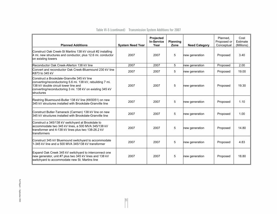
121
Table VI-5 (continued) Transmission System Additions for 2007
Planned Additions System Need Year
ProjectedIn-Service
YearPlanning
Zone Need Category
Planned,Proposed orConceptual
CostEstimate(Millions)
Construct Oak Creek-St Martins 138 kV circuit #2 installing4 mi. new structures and conductor, plus 12.6 mi. conductoron existing towers
2007 2007 5 new generation Proposed 3.40
Reconductor Oak Creek-Allerton 138 kV line 2007 2007 5 new generation Proposed 2.00
Convert and reconductor Oak Creek-Bluemound 230 kV lineK873 to 345 kV
2007 2007 5 new generation Proposed 19.00
Construct a Brookdale-Granville 345 kV lineconverting/reconductoring 5.6 mi. 138 kV, rebuilding 7 mi.138 kV double circuit tower line andconverting/reconductoring 3 mi. 138 kV on existing 345 kVstructures
2007 2007 5 new generation Proposed 19.30
Restring Bluemound-Butler 138 kV line (KK5051) on new345 kV structures installed with Brookdale-Granville line
2007 2007 5 new generation Proposed 1.10
Construct Butler-Tamarack (Carmen) 138 kV line on new345 kV structures installed with Brookdale-Granville line
2007 2007 5 new generation Proposed 1.00
Construct a 345/138 kV switchyard at Brookdale toaccommodate two 345 kV lines, a 500 MVA 345/138 kVtransformer and 4-138 kV lines plus two 138-26.2 kVtransformers
2007 2007 5 new generation Proposed 14.80
Construct 345 kV Bluemound switchyard to accommodate1-345 kV line and a 500 MVA 345/138 kV transformer
2007 2007 5 new generation Proposed 4.83
Expand Oak Creek 345 kV switchyard to interconnect onenew generator, unit #7 plus two 345 kV lines and 138 kVswitchyard to accommodate new St. Martins line
2007 2007 5 new generation Proposed 18.80
Full Report – September 2003

12210-Year Transmission Assessm
ent
Table VI-5 (continued) Transmission System Additions for 2007
Planned Additions System Need Year
ProjectedIn-Service
YearPlanning
Zone Need Category
Planned,Proposed orConceptual
CostEstimate(Millions)
Reconnect Oak Creek unit #7 to 345 kV switchyard 2007 2007 5 new generation Proposed 0.40
Install two 345 kV series breakers at Pleasant Prairie onlines to Racine (L631) and Zion (L2221)
2007 2007 5 new generation Proposed 2.10
Replace seven 138 kV overdutied breakers at Bluemound 2007 2007 5 new generation Proposed 2.45
Defined in previous 10-Year Assessment
Revised in scope from previous 10-Year Assessment
New to this 10-Year Assessment

123
Table VI-6 Transmission System Additions for 2008
Planned AdditionsSystem Need
Year
ProjectedIn-Service
YearPlanning
Zone Need Category
Planned,Proposed orConceptual
CostEstimate(Millions)
Construct Stone Lake-Arrowhead 345 kV line 1997 2008 1
service limitation,reliability, importcapability and Westonstability
Planned 158.20
Rebuild Weston-Northpoint 115 kV line 2008 2008 1
achieve transfercapability associatedwith Arrowhead-Weston
Proposed 3.30
Rebuild Kelly-Whitcomb 115 kV line 2008 2008 1
achieve transfercapability associatedwith Arrowhead-Weston
Proposed 4.16
Install 2-25 MVAR capacitor banks at Arpin 138 kV 2008 2008 1 transfer capability Proposed 0.50
Install 2-25 MVAR capacitor banks at Arpin 115 kV 2008 2008 1 transfer capability Proposed 0.50
Install 2-40 MVAR capacitor banks at Weston 115 kV 2008 2008 1 transfer capability Proposed 7.96
Install 3-52 MVAR capacitor banks at Rocky Run 115 kV 2008 2008 1 transfer capability Proposed 1.00
Install 65 MVAR capacitor bank at Arrowhead 230 kV 2008 2008 1 transfer capability Proposed 2.00
Replace 138/69 kV transformer at Sigel 2008 2008 1 reliability Proposed 1.00
Install additional 4.1 MVAR capacitor bank at Ripon 69 kV 2008 2008 1 reliability Proposed 0.20
Replace 138/69 kV transformer at Metomen 2008 2008 1 reliability Conceptual 1.00
Construct St. Germain-Boulder Junction 115 kV line 2008 2008 1 T-D interconnection Conceptual 8.19
Install a second 138/69 kV transformer at Hillman 2008 2008 3 reliability Proposed 3.90
Rebuild/convert South Fond du Lac-Springbrook 69 kV to138 kV
2008 2008 3 reliability Conceptual 8.20
Full Report – September 2003

12410-Year Transmission Assessm
ent
Table VI-6 (continued) Transmission System Additions for 2008
Planned AdditionsSystem Need
Year
ProjectedIn-Service
YearPlanning
Zone Need Category
Planned,Proposed orConceptual
CostEstimate(Millions)
Construct 138 kV bus and install a 138/69 kV transformer atSpringbrook
2008 2008 3 reliability Conceptual 2.00
Convert Rock River to Bristol to 138 kV operation; rebuildBristol with a new 138 kV bus
2008 2008 3 reliability Conceptual 5.50
Reconductor Pleasant Valley-Saukville 138 kV line 2008 2008 5 new generation Proposed 3.00
Reconductor Pleasant Valley-St Lawrence 138 kV line 2008 2008 5 new generation Proposed 2.81
Reconductor Cornell-Range Line 138 kV line 2008 2008 5 new generation Proposed 6.00
Uprate Kansas-Ramsey6 138 kV line 2008 2008 5new generation,reliability
Proposed 0.13
Uprate Oak Creek-Ramsey6 138 kV line 2008 2008 5new generation,reliability
Proposed 0.13
Defined in previous 10-Year Assessment
Revised in scope from previous 10-Year Assessment
New to this 10-Year Assessment

125
Table VI-7 Transmission System Additions for 2009
Planned AdditionsSystem Need
Year
ProjectedIn-Service
YearPlanning
Zone Need Category
Planned,Proposed orConceptual
CostEstimate(Millions)
Construct Fitzgerald-Omro Industrial 69 kV line 2009 2009 1 reliability Conceptual 5.30
Uprate Wautoma-Berlin 69 kV line terminal equipment 2009 2009 1 reliability Proposed 0.15
Rebuild Hiawatha-Pine River-Straits 69 kV to 138 kV 2009 2009 2 reliability, condition Proposed 40.10
Construct 138 kV bus and install a 138/69 kV, 50 MVAtransformer at Pine River
2009 2009 2 reliability Proposed 6.09
String second Hiawatha-Indian Lake 138 kV circuit onexisting structures
2009 2009 2reliability, servicelimitation
Planned 0.20
Convert rebuilt Hiawatha-Indian Lake circuit (operated at 69kV) to 138 kV
2009 2009 2reliability, servicelimitation
Planned 2.10
Install 138 kV ring bus at Hiawatha SS 2009 2009 2reliability, servicelimitation
Planned 1.91
Install 138 kV substation modifications at Indian Lake SS 2009 2009 2reliability, servicelimitation
Planned 1.85
Install 138 kV ring bus at Straits SS 2009 2009 2reliability, servicelimitation
Planned 1.91
Convert South Lake Geneva to Twin Lakes 69 kV line to 138kV
2009 2009 3 reliability Conceptual 3.00
Construct new 138 kV bus and install a 138/69 kV 100 MVAtransformer at South Lake Geneva
2009 2009 3 reliability Conceptual 6.00
Construct new 138 kV line from Twin Lakes to Spring Valley 2009 2009 3 reliability Conceptual 15.00
Construct new 138 kV line from South Lake Geneva toNorth Lake Geneva
2009 2009 3 reliability Conceptual 6.00
Replace Columbia-Manley Sand 69 kV line terminalequipment
2009 2009 3 reliability Conceptual 0.30
Convert Hillman to Eden 69 kV line to 138 kV 2009 2009 3 reliability Proposed 13.00
Full Report – September 2003

12610-Year Transmission Assessm
ent
Table VI-7 (continued) Transmission System Additions for 2009
Planned Additions System Need Year
ProjectedIn-Service
YearPlanning
Zone Need Category
Planned,Proposed orConceptual
CostEstimate(Millions)
Construct new 69 kV line from Brooklyn to BellevilleSubstation
2009 2009 3 reliability Proposed 5.00
Construct 345 kV line from Rockdale through Kegonsa toWest Middleton
2009 2009 3 reliability Proposed 38.45
Construct a 345 kV bus and install a 345/138 kV 500 MVAtransformer at substation at West Middleton
2009 2009 3 reliability Proposed 12.00
Construct a second West Middleton-Walnut 69 kV circuit,use spare pipe from Walnut to Terrace Avenue riser anddouble circuit the overhead line the remainder of the circuitrun to West Middleton
2009 2009 3 reliability Proposed 11.00
Rebuild and convert West Middleton-Spring Green 69 kVline to 138 kV
2009 2009 3 reliability Proposed 20.00
Construct 138 kV bus and install a 138/69 kV 100 MVAtransformer at Stagecoach
2009 2009 3 reliability Conceptual 3.00
Construct Spring Green-Prairie du Sac 69 kV line 2009 2009 3reliability, T-Dinterconnection
Proposed 12.00
Rebuild Rockdale-Jefferson-Concord 138 kV line to doublecircuit 345/138 kV on existing right of way
2007 2009 3 and 5reliability, servicelimitation
Proposed 22.18
Construct a 345 kV bus and install a 345/138 kV, 500 MVAtransformer at Concord
2007 2009 3 and 5 reliability Proposed 12.95
String a new Ellinwood-Sunset Pt 138 kV line on existingstructures
2009 2009 4 reliability Proposed 2.50
Construct Morgan-Werner West 345 kV line 2004 2009 4reliability, servicelimitation
Proposed 99.73
Install second 500 MVA 345/138 kV transformer at OakCreek
2009 2009 5 new generation Proposed 8.40

127
Table VI-7 (continued) Transmission System Additions for 2009
Planned Additions System Need Year
ProjectedIn-Service
YearPlanning
Zone Need Category
Planned,Proposed orConceptual
CostEstimate(Millions)
Expand 345 kV switchyard at Oak Creek to interconnect onenew generator
2009 2009 5 new generation Proposed 4.20
Defined in previous 10-Year AssessmentRevised in scope from previous 10-Year Assessment
New to this 10-Year Assessment
Full Report – September 2003

12810-Year Transmission Assessm
ent
Table VI-8 Transmission System Additions for 2010
Planned Additions System Need Year
ProjectedIn-Service
YearPlanning
Zone Need Category
Planned,Proposed orConceptual
CostEstimate(Millions)
Uprate Sherman Street-Hilltop-Maine 115 kV line - scopeTBD
2010 2010 1 reliability Conceptual 1.12
Uprate Whitcomb-Deer Trail 69 kV line terminal equipment 2010 2010 1 reliability Proposed 0.97
Uprate Paddock-Shirland 69 kV line terminal equipment 2010 2010 3 reliability Conceptual 0.20
Uprate Colley Road 138/69 kV transformer to 116 MVAsummer emergency
2010 2010 3 reliability Conceptual 0.25
Install a 69 kV 16.32 MVAR capacitor bank at KilbournSubstation
2010 2010 3 reliability Conceptual 0.50
Reconnect the 138/69 kV transformers at Kilbourn onseparate breakers to operate individually and replace the 47MVA transformer with a 93 MVA transformer
2010 2010 3 reliability Conceptual 2.00
Convert Bark River-Lannon 138 kV line to 345 kV 2009 2010 3 and 5 reliability Proposed 0.55
Construct a Concord-Bark River 345 kV line 2009 2010 3 and 5 reliability Proposed 24.39
Defined in previous 10-Year Assessment
Revised in scope from previous 10-Year Assessment
New to this 10-Year Assessment

129
Table VI-9 Transmission System Additions for 2011
Planned Additions System Need Year
ProjectedIn-Service
YearPlanning
Zone Need Category
Planned,Proposed orConceptual
CostEstimate(Millions)
Uprate Weston-Black Brook 115 kV line - scope TBD 2011 2011 1 reliability Conceptual 1.50
Uprate West Middleton-Pheasant Branch 69 kV line 2011 2011 3 reliability Conceptual 1.00
Install 2-16.3 MVAR capacitor bank at Apple Hills 138 kV 2011 2011 4 reliability Proposed 1.18
Construct a second Dunn Rd-Egg Harbor 69 kV line 2011 2011 4 reliability Proposed 6.15
Construct a Northside-City Limits 138 kV line 2011 2011 4 reliability Proposed 3.07
Replace substation equipment at both Arcadian 138 kV andWaukesha 138 kV associated with KK9962
2011 2011 5new generation, T-DInterconnection
Proposed 5.70
Replace two existing 345/138 transformers at Arcadian with500 MVA units
2011 2011 5reliability, newgeneration, T-DInterconnection
Proposed 4.01
Expand Oak Creek 138 kV switchyard to reconnect units #6and #9
2011 2011 5 new generation Proposed 6.85
Expand 345 kV switchyard at Bluemound to accommodatethree additional 345 kV lines and two additional 500 MVA345/138 kV transformers
2011 2011 5 new generation Proposed 16.90
Reconnect Oak Creek unit #8 to 345 kV switchyard 2011 2011 5 new generation Proposed 0.40
Convert and reconductor Oak Creek-Bluemound 230 kV lineK862 to 345 kV and loop into Arcadian 345 kV substation
2011 2011 5 new generation Proposed 34.80
Construct Oak Creek-Racine 345 kV line with 4 mi newstructures and conductor, plus convert 9.6 mi. 138 kV lineKK812 to 345 kV
2011 2011 5 new generation Proposed 8.10
Full Report – September 2003

130
Table VI-9 (continued) Transmission System Additions for 2011
Planned Additions System Need Year
ProjectedIn-Service
YearPlanning
Zone Need Category
Planned,Proposed orConceptual
CostEstimate(Millions)
Reroute Brookdale-Granville 345 kV line into expandedBluemound 345 kV switchyard
2011 2011 5 new generation Proposed 0.30
Replace 22-138 kV overdutied breakers at Harbor, Everettand Haymarket Substations
2011 2011 5 new generation Proposed 7.65
Expand Oak Creek 345 kV switchyard to interconnect threenew generators, unit #8 and two 345 kV lines, plusinstallation of eight 345 kV series breakers for stabilitypurposes
2011 2011 5 new generation Proposed 21.50
Defined in previous 10-Year Assessment
Revised in scope from previous 10-Year Assessment
New to this 10-Year Assessment
10-Year Transmission Assessm
ent

131
Table VI-10 Transmission System Additions for 2012
Planned Additions System Need Year
ProjectedIn-Service
YearPlanning
Zone Need Category
Planned,Proposed orConceptual
CostEstimate(Millions)
Install additional 13.6 MVAR capacitor bank at Clear Lake115 kV
2012 2012 1 reliability Conceptual 0.49
Uprate Metomen-Ripon 69 kV line - scope TBD 2012 2012 1 reliability Conceptual 1.50
Install a second 138/69, 47 MVA transformer at Wautoma 2012 2012 1 reliability Conceptual 1.20
Rebuild Blaney Park-Munising 69 kV to 138 kV 2012 2012 2 reliability, condition Conceptual 19.31
Construct 345 kV line from Paddock to new Verona 345 kVswitchyard; loop Kegonsa-West Middleton 345 kV line intoVerona
2012 2012 3reliability, transfercapability
Conceptual 119.30
Construct 69 kV line Eden through Muscoda to RichlandCenter
2012 2012 3 reliability Conceptual 12.00
Move Lone Rock 69 kV phase shifter to Richland Center 2012 2012 3 reliability Conceptual 0.50
Defined in previous 10-Year Assessment
Revised in scope from previous 10-Year Assessment
New to this 10-Year Assessment
Full Report – September 2003

132
Table VI-11 Transmission System Additions for Zone 1
Planned Additions System Need Year
ProjectedIn-Service
YearPlanning
Zone Need Category
Planned,Proposed orConceptual
Construct an Endeavor-Wautoma/Portage Tap 69 kV line 2003 2003 1 T-D Interconnection Planned
Uprate Whitcomb 115/69 kV transformer 2002 2003 1 reliability Planned
Construct an Omro Industrial-Berlin/Omro 69 kV line 2004 2004 1 T-D Interconnection Planned
Move Reedsburg 6 MVA D-SMES unit to Clear Lake 115 kV 2004 2004 1 reliability Proposed
Install 69 kV phase shifter or fixed reactor at Council Creek 2002 2004 1 reliability Proposed
Convert Pine-Grandfather-Tomahawk-Eastom 46 kV lines to115 kV
2001 2004 1 reliability Planned
Uprate North Randolph-Ripon 69 kV line terminal equipment 2002 2004 1 reliability Planned
Install 4.1 MVAR capacitor bank at Ripon 69 kV 2003 2004 1 reliability Planned
Install additional 4.1 MVAR capacitor bank at Berlin 69 kV 2004 2004 1 reliability Planned
Construct an Eagle River-Cranberry/Three Lakes 115 kVline
2005 2005 1 T-D interconnection Proposed
Install two-8.2 MVAR capacitor banks at Council Creek 138kV
2004 2005 1 reliability Proposed
Rebuild Skanawan-Highway 8 115 kV line to double circuit115 kV
2005 2005 1 reliability Planned
Uprate Bunker Hill-Pine 115 kV line terminal equipment 2005 2005 1 reliability Planned
Move 10 MVAR capacitor bank from Highway 8 to Hodag115 kV
2005 2005 1 reliability Planned
Reconductor Wien-McMillan 115 kV (ATC,MEWD) 2005 2005 1 reliability Proposed
10-Year Transmission Assessm
ent

133
Table VI-11 (continued) Transmission System Additions for Zone 1
Planned Additions System Need Year
ProjectedIn-Service
YearPlanning
Zone Need Category
Planned,Proposed orConceptual
Uprate Metomen-N Fond du Lac 69 kV line terminalequipment
2005 2005 1 reliability Proposed
Construct 138 kV line from Venus to new CrandonSubstation (operate at 115 kV)
2005 2005 1 T-D interconnections Proposed
Construct Clear Lake-Arnett Road 115 kV line 2005 2006 1 T-D interconnection Proposed
Construct Weston-Stone Lake 345 kV line, Weston 345 kVswitchyard, and replace the 200 MVA 345/115 kVtransformer with two 500 MVA transformers
1997 2006 1
service limitation,reliability, importcapability and Westonstability
Planned
Uprate Weston-Kelly 115 kV line - scope TBD 2006 2006 1new generation,reliability
Proposed
Construct 138 kV line from Crandon to new Laona andoperate at 115 kV
2005 2006 1 T-D interconnection Proposed
Install two-16.3 MVAR capacitor banks at Wautoma 138 kV 2006 2006 1 reliability Proposed
Install two-6.8 MVAR capacitor banks at Antigo 115 kV 2006 2006 1 reliability Proposed
Uprate Weston-Morrison-Sherman St. 115 kV line - scopeTBD
2007 2007 1 reliability Proposed
Uprate Weston-Sherman St. 115 kV line - scope TBD 2007 2007 1 reliability Proposed
Construct Cranberry-Conover 138 kV line 2007 2007 1transfer capability,reliability
Proposed
Install 138/115 kV 100 MVA transformer at Cranberry 2007 2007 1transfer capability,reliability
Proposed
Construct Stone Lake-Arrowhead 345 kV line 1997 2008 1
service limitation,reliability, importcapability and Westonstability
Proposed
Full Report – September 2003

13410-Year Transmission Assessm
ent
Table VI-11 (continued) Transmission System Additions for Zone 1
Planned Additions System Need Year
ProjectedIn-Service
YearPlanning
Zone Need Category
Planned,Proposed orConceptual
Rebuild Weston-Northpoint 115 kV line 2008 2008 1achieve transfercapability associatedwith Arrowhead-Weston
Proposed
Rebuild Kelly-Whitcomb 115 kV line 2008 2008 1achieve transfercapability associatedwith Arrowhead-Weston
Proposed
Install two-25 MVAR capacitor banks at Arpin 138 kV 2008 2008 1 transfer capability Proposed
Install two-25 MVAR capacitor banks at Arpin 115 kV 2008 2008 1 transfer capability Proposed
Install two-40 MVAR capacitor banks at Weston 115 kV 2008 2008 1 transfer capability Proposed
Install three-52 MVAR capacitor banks at Rocky Run 115 kV 2008 2008 1 transfer capability Proposed
Install 65 MVAR capacitor bank at Arrowhead 230 kV 2008 2008 1 transfer capability Proposed
Replace 138/69 kV transformer at Sigel 2008 2008 1 reliability Proposed
Install additional 4.1 MVAR capacitor bank at Ripon 69 kV 2008 2008 1 reliability Proposed
Replace 138/69 kV transformer at Metomen 2008 2008 1 reliability Conceptual
Construct St. Germain-Boulder Junction 115 kV line 2008 2008 1 T-D interconnection Conceptual
Construct Fitzgerald-Omro Industrial 69 kV line 2009 2009 1 reliability Conceptual
Uprate Wautoma-Berlin 69 kV line terminal equipment 2009 2009 1 reliability Proposed
Uprate Sherman Street-Hilltop-Maine 115 kV line - scopeTBD
2010 2010 1 reliability Conceptual

135
Table VI-11 (continued) Transmission System Additions for Zone 1
Planned Additions System Need Year
ProjectedIn-Service
YearPlanning
Zone Need CategoryPlanned, Proposed
or Conceptual
Uprate Whitcomb-Deer Trail 69 kV line terminal equipment 2010 2010 1 reliability Proposed
Uprate Weston-Black Brook 115 kV line - scope TBD 2011 2011 1 reliability Conceptual
Install additional 13.6 MVAR capacitor bank at Clear Lake115 kV
2012 2012 1 reliability Conceptual
Uprate Metomen-Ripon 69 kV line - scope TBD 2012 2012 1 reliability Conceptual
Install a second 138/69, 47 MVA transformer at Wautoma 2012 2012 1 reliability Conceptual
Full Report – September 2003

13610-Year Transmission Assessm
ent
Table VI-12 Transmission System Additions for Zone 2
Planned Additions System Need Year
ProjectedIn-Service
YearPlanning
Zone Need Category
Planned,Proposed orConceptual
Construct Elevation Tap-Elevation 69 kV line 2003 2003 2 T-D Interconnection Planned
Rebuild Indian Lake to Glen Jenks to four circuits - two 138kV, two 69 kV
2003 2004 2reliability, servicelimitation
Planned
Expand Indian Lake 69 kV to accommodate Indian Lake-Glen Jenks 69 kV line
2003 2004 2reliability, servicelimitation
Planned
Uprate Cedar-M38 138 kV line (167 degrees) 2004 2004 2reliability, servicelimitation
Planned
Uprate Cedar-Freeman 138 kV line (167 degrees) 2004 2004 2 reliability Planned
Uprate Freeman-Presque Isle 138 kV line (167 degrees) 2004 2004 2 reliability Planned
Uprate Presque Isle-Cedar 138 kV line (167 degrees) 2004 2004 2 reliability Planned
Construct Hiawatha-Engadine 69 kV line 2003 2004 2 reliability Planned
Uprate Stiles-Plains double circuit 138 kV line 1996 2004 2 and 4reliability, servicelimitation, condition
Proposed
Install a second 138/69 kV transformer at Straits 2005 2005 2 reliability Proposed
Rebuild from Nordic SS to Randville SS (5 miles) of singleckt 69 kV line to double circuit 69 kV
2005 2005 2 reliability, condition Proposed
Rebuild and convert one Hiawatha-Indian Lake 69 kV circuitto double circuit 138 kV standards, string one circuit initiallyand operate at 69 kV
2004 2005 2reliability, servicelimitation
Planned

137
Table VI-12 (continued) Transmission System Additions for Zone 2
Planned Additions System Need Year
ProjectedIn-Service
YearPlanning
Zone Need Category
Planned,Proposed orConceptual
Install two-5.4 MVAR capacitor banks at Iron River 69 kV 2006 2006 2 reliability Proposed
Rebuild/convert Conover-Iron River-Plains 69 kV line to 138kV
2007 2007 2transfer capability,reliability
Proposed
Construct 138 kV bus and install a 138/69 kV, 50 MVAtransformer at Conover
2007 2007 2transfer capability,reliability
Proposed
Construct 138 kV bus and install a 138/69 kV, 50 MVAtransformer at Iron River
2007 2007 2transfer capability,reliability
Proposed
Rebuild Hiawatha-Pine River-Straits 69 kV to 138 kV 2009 2009 2 reliability, condition Proposed
Construct 138 kV bus and install a 138/69 kV, 50 MVAtransformer at Pine River
2009 2009 2 reliability Proposed
String second Hiawatha-Indian Lake 138 kV circuit onexisting structures
2009 2009 2reliability, servicelimitation
Planned
Convert rebuilt Hiawatha-Indian Lake circuit (operated at 69kV) to 138 kV
2009 2009 2reliability, servicelimitation
Planned
Install 138 kV ring bus at Hiawatha SS 2009 2009 2reliability, servicelimitation
Planned
Install 138 kV substation modifications at Indian Lake SS 2009 2009 2reliability, servicelimitation
Planned
Install 138 kV ring bus at Straits SS 2009 2009 2reliability, servicelimitation
Planned
Rebuild Blaney Park-Munising 69 kV to 138 kV 2012 2012 2 reliability, condition Conceptual
Full Report – September 2003

13810-Year Transmission Assessm
ent
Table VI-13 Transmission System Additions for Zone 3
Planned Additions System Need Year
ProjectedIn-Service
YearPlanning
Zone Need Category
Planned,Proposed orConceptual
Reconductor Christiana-Kegonsa portion of Christiana toFitchburg 138 kV line
2005 2003 3 reliability Planned
Reconfigure 69/138 kV circuits between Rock River andJanesville to create Rock River-Janesville and Rock River-Sunrise 138 kV circuits
2004 2003 3reliability, newgeneration
Planned
Reconductor Colley Road-Blackhawk 138 kV line 2003 2003 3reliability, servicelimitation
Planned
Construct 138 kV switchyard at Riverside generation site(Townline Road Substation)
2003 2003 3reliability, newgeneration
Planned
Construct 138 kV double circuit line from Townline Road toRock River
2003 2003 3reliability, newgeneration
Planned
Reconnect NW Beloit 69 kV load to Paddock-Blackhawk 138kV line
2003 2003 3 reliability Planned
Install 16.32 MVAR capactor bank at Oregon or Brooklyn 69kV
2004 2004 3 reliability Planned
Convert Kilbourn-Zobel 69 kV line to 138 kV 2004 2004 3 reliability Planned
Construct Artesian-Zobel 138 kV line 2004 2004 3 reliability Planned
Construct second East Campus-Walnut 69 kV line 2003 2004 3new generation,reliability
Planned
Replace McCue-Sheepskin 69 kV line terminal equipmentand increase conductor clearance
2004 2004 3reliability, newgeneration
Planned
Replace the existing 187 MVA 138/69 kV transformer atSycamore with two 100 MVA transformers and reconfigure138 kV bus
2004 2004 3new generation,reliability
Planned
Construct 69 kV switchyard at Tokay 2004 2004 3 T-D interconnection Planned

139
Table VI-13 (continued) Transmission System Additions for Zone 3
Planned Additions System Need Year
ProjectedIn-Service
YearPlanning
Zone Need CategoryPlanned, Proposed
or Conceptual
Construct Fitchburg-Tokay-Westowne 69 kV undergroundline
2004 2004 3 T-D interconnection Planned
Rebuild Russell-Janesville 138 kV line 2004 2004 3new generation,service limitation
Planned
Reconductor Russell-Rockdale 138 kV line 2004 2004 3new generation,service limitation
Planned
Install a second 138/69 kV transformer at North Randolph 2004 2004 3 reliability Planned
Install 24 MVAR capacitor bank at new Birchwood 138 kV 2004 2004 3 reliability Planned
Reconductor Blount-Ruskin 69 kV line 2003 2004 3reliability, newgeneration
Planned
Reconductor Blount-Ruskin Tap 69 kV line 2003 2004 3reliability, newgeneration
Planned
Rebuild Kegonsa-McFarland-Femrite 69 kV line to 138 kVand operate at 69 kV
2004 2004 3reliability, newgeneration
Planned
Rebuild Femrite-Royster 69 kV line 2004 2004 3reliability, newgeneration
Planned
Install 16.32 MVAR capacitor bank at Lone Rock 2004 2004 3 reliability Planned
Expand Walnut Substation to interconnect IC029 generation 2004 2004 3 new generation Planned
Install 16.3 MVAR capacitor bank at Kegonsa 69 kV 2004 2004 3 new generation Planned
Install 20.4 MVAR capacitor bank at North Madison 69 kV 2004 2004 3 new generation Planned
Install 24.5 MVAR capacitor bank at Cross Country 138 kV 2004 2004 3 new generation Planned
Install 12.2 MVAR capacitor bank at Waunakee 69 kV 2004 2004 3 new generation Planned
Install 7.2 MVAR capacitor banks on distribution systemat/near Tokay
2004 2004 3 new generation Planned
Full Report – September 2003

14010-Year Transmission Assessm
ent
Table VI-13 (continued) Transmission System Additions for Zone 3
Planned Additions System Need Year
ProjectedIn-Service
YearPlanning
Zone Need Category
Planned,Proposed orConceptual
Install 7.2 MVAR capacitor banks on distribution systemat/near West Middleton
2004 2004 3 new generation Planned
Replace 138/69 kV transformers at Fitchburg with 187 MVAunits
2003 2004 3reliability, newgeneration
Planned
Construct second Wempletown-Paddock 345 kV circuit;reconfigure existing circuit
2004 2004 3reliability, servicelimitation
Proposed
Uprate Portage-Columbia double circuit 138 kV line terminalequipment
2004 2005 3 reliability Planned
Rebuild Turtle-Bristol 69 kV line to 138 kV and operate at 69kV
2004 2005 3condition, reliability,new generation
Planned
Construct new 69 kV line from Columbia to Rio to feed theproposed Wyocena substation
2004 2005 3T-D interconnection,reliability
Proposed
Construct new line from West Darien to Southwest Delavanto Delavan at 138 kV, operate at 69 kV
2005 2005 3 T-D interconnection Planned
Uprate Rockdale to Jefferson 138 kV line 2005 2005 3reliability, servicelimitation
Proposed
Uprate Rockdale to Boxelder 138 kV line 2005 2005 3 reliability Proposed
Construct 138 kV bus at Kegonsa and terminate bothChristiana-Fitchburg circuits into Kegonsa
2005 2005 3reliability, newgeneration
Planned
Build new breaker and a half 345/138 kV substation on siteadjacent to existing North Madison substation and replaceexisting transformers with two new 500 MVA units
2005 2006 3reliability, newgeneration
Planned
Install 16.32 MVAR capacitor bank at Verona 69 kV 2006 2006 3 reliability Proposed

141
Table VI-13 (continued) Transmission System Additions for Zone 3
Planned Additions System Need Year
ProjectedIn-Service
YearPlanning
Zone Need Category
Planned,Proposed orConceptual
Install replacement 16.32 MVAR capacitor bank at RichlandCenter substation
2006 2006 3 reliability Proposed
Convert Columbia-North Madison 138 kV line to 345 kV 2005 2006 3reliability, newgeneration
Planned
Install/upgrade capacitor bank at South Monroe 69 kV to 24MVAR
2006 2006 3 reliability Proposed
Construct a Jefferson-Lake Mills-Stony Brook 138 kV line 2005 2006 3reliability, T-Dinterconnection
Proposed
Loop the Femrite to Royster 69 kV line into AGA Gas 2007 2007 3 reliability Proposed
Convert Kegonsa-McFarland-Femrite 69 kV line to 138 kV 2007 2007 3reliability, newgeneration
Proposed
Construct South Beaver Dam-North Beaver Dam 138 kV line 2007 2007 3 reliability Proposed
Convert Academy-South Beaver Dam 69 kV line to 138 kV 2007 2007 3 reliability Proposed
Construct Sprecher-Femrite 138 kV line 2007 2007 3reliability, newgeneration
Proposed
Install 138/69 kV transformer at Femrite 2007 2007 3reliability, newgeneration
Proposed
Install 138/69 kV transformer at Reiner 2007 2007 3reliability, newgeneration
Proposed
Convert Sycamore-Reiner-Sprecher from 69 kV to 138 kV 2007 2007 3 reliability Proposed
Construct new 138 kV bus and 138/69 kV 100 MVAtransformer at Verona Substation
2007 2007 3 reliability Conceptual
Construct new 138 kV line from Verona to SoutheastFitchburg Substation
2007 2007 3 reliability Conceptual
Install 10 MVAR capacitor bank at Jefferson 138 kV 2007 2007 3 reliability Proposed
Full Report – September 2003

14210-Year Transmission Assessm
ent
Table VI-13 (continued) Transmission System Additions for Zone 3
Planned Additions System Need Year
ProjectedIn-Service
YearPlanning
Zone Need Category
Planned,Proposed orConceptual
Install two-13 MVAR capacitor banks at Concord 138 kV 2007 2007 3 reliability Proposed
Install a second 138/69 kV transformer at Hillman 2008 2008 3 reliability Proposed
Rebuild/convert South Fond du Lac-Springbrook 69 kV to138 kV
2008 2008 3 reliability Conceptual
Construct 138 kV bus and install a 138/69 kV transformer atSpringbrook
2008 2008 3 reliability Conceptual
Convert Rock River to Bristol to 138 kV operation; rebuildBristol with a new 138 kV bus
2008 2008 3 reliability Conceptual
Convert South Lake Geneva to Twin Lakes 69 kV line to 138kV
2009 2009 3 reliability Conceptual
Construct new 138 kV bus and install a 138/69 kV 100 MVAtransformer at South Lake Geneva
2009 2009 3 reliability Conceptual
Construct new 138 kV line from Twin Lakes to Spring Valley 2009 2009 3 reliability Conceptual
Construct new 138 kV line from South Lake Geneva to NorthLake Geneva
2009 2009 3 reliability Conceptual
Replace Columbia-Manley Sand 69 kV line terminalequipment
2009 2009 3 reliability Conceptual
Convert Hillman to Eden 69 kV line to 138 kV 2009 2009 3 reliability Proposed
Construct new 69 kV line from Brooklyn to BellevilleSubstation
2009 2009 3 reliability Proposed
Construct 345 kV line from Rockdale through Kegonsa toWest Middleton
2009 2009 3 reliability Proposed
Construct a 345 kV bus and install a 345/138 kV 500 MVAtransformer at West Middleton
2009 2009 3 reliability Proposed

143
Table VI-13 (continued) Transmission System Additions for Zone 3
Planned Additions System Need Year
ProjectedIn-Service
YearPlanning
Zone Need Category
Planned,Proposed orConceptual
Construct a second West Middleton-Walnut 69 kV circuit,use spare pipe from Walnut to Terrace Avenue riser anddouble circuit the overhead line the remainder of the circuitrun to West Middleton
2009 2009 3 reliability Proposed
Rebuild and convert West Middleton-Spring Green 69 kVline to 138 kV
2009 2009 3 reliability Proposed
Construct 138 kV bus and install a 138/69 kV 100 MVAtransformer at Stagecoach
2009 2009 3 reliability Conceptual
Construct Spring Green-Prairie du Sac 69 kV line 2009 2009 3reliability, T-Dinterconnection
Proposed
Rebuild Rockdale-Jefferson-Concord 138 kV line to doublecircuit 345/138 kV on existing right-of-way
2007 2009 3 and 5reliability, servicelimitation
Proposed
Construct a 345 kV bus and install a 345/138 kV, 500 MVAtransformer at Concord
2007 2009 3 and 5 reliability Proposed
Uprate Paddock-Shirland 69 kV line terminal equipment 2010 2010 3 reliability Conceptual
Uprate Colley Road 138/69 kV transformer to 116 MVAsummer emergency
2010 2010 3 reliability Conceptual
Install a 69 kV 16.32 MVAR capacitor bank at KilbournSubstation
2010 2010 3 reliability Conceptual
Reconnect the 138/69 kV transformers at Kilbourn onseparate breakers to operate individually and replace the 47MVA transformer with a 93 MVA transformer
2010 2010 3 reliability Conceptual
Convert Bark River-Lannon 138 kV line to 345 kV 2009 2010 3 and 5 reliability Proposed
Construct a Concord-Bark River 345 kV line 2009 2010 3 and 5 reliability Proposed
Uprate West Middleton-Pheasant Branch 69 kV line 2011 2011 3 reliability Conceptual
Full Report – September 2003

14410-Year Transmission Assessm
ent
Table VI-13 (continued) Transmission System Additions for Zone 3
Planned Additions System Need Year
ProjectedIn-Service
YearPlanning
Zone Need Category
Planned,Proposed orConceptual
Construct 345 kV line from Paddock to new Verona 345 kVswitchyard; loop Kegonsa-West Middleton 345 kV line intoVerona
2012 2012 3reliability, transfercapability
Conceptual
Construct 69 kV line Eden through Muscoda to RichlandCenter
2012 2012 3 reliability Conceptual
Move Lone Rock 69 kV phase shifter to Richland Center 2012 2012 3 reliability Conceptual

145
Table VI-14 Transmission System Additions for Zone 4
Planned Additions System Need Year
ProjectedIn-Service
YearPlanning
Zone Need Category
Planned,Proposed orConceptual
Replace 200 A metering CT at Sheboygan Falls 69 kV 2003 2003 4 reliability Planned
Replace 400 A CT at S Fond du Lac 69 kV 2003 2003 4 reliability Planned
Retap metering CT at Lodestar 138 kV 2003 2003 4 reliability Planned
Construct 138 kV line from Mullet River to N Mullet Riverand convert N Mullet River to Plymouth Sub #1 from 69 kVto 138 kV
2003 2003 4 reliability Planned
Uprate Stiles-Plains double circuit 138 kV line 1996 2004 2 and 4reliability, servicelimitation, condition
Proposed
Construct/rebuild double circuit 138/69 kV line from Pulliamto Bayport
2004 2004 4reliability, T-Dinterconnection
Planned
Install two-16.3 MVAR capacitor bank at Canal 69 kV 2003 2004 4 reliability Proposed
Rebuild the Morgan-Falls-Pioneer-Stiles 138 kV line 2003 2004 4service limitation,facility condition
Planned
Install 345 kV breaker for Edgewater 345/138 kVtransformer (TR-22)
2003 2004 4 reliability Planned
Replace two 800 A line traps at Edgewater 138 kV 2003 2004 4 reliability Planned
Replace 345/138 kV transformer at Edgewater 2005 2005 4 reliability Planned
Replace 600 A CT at N Fond du Lac 138 kV 2005 2005 4 reliability Planned
Uprate Morgan-White Clay 138 kV line 2005 2005 4reliability, servicelimitation
Proposed
Construct 138 kV line from Erdman to Howard’s Grove 2006 2006 4 T-D interconnection Planned
Full Report – September 2003

14610-Year Transmission Assessm
ent
Table VI-14 (continued) Transmission System Additions for Zone 4
Planned Additions System Need Year
ProjectedIn-Service
YearPlanning
Zone Need Category
Planned,Proposed orConceptual
Construct a 345/138 kV switchyard at a new Werner WestSS; install a 345/138 kV transformer. Loop existing RockyRun to North Appleton 345 kV and existing Werner to WhiteLake 138 kV lines into Werner West
2004 2006 4 reliability, service limitation Proposed
Construct 2.5 miles of 138 kV line from Lodestar toSheboygan Falls
2003 2006 4 reliability Proposed
Install a 138/69 kV, 60 MVA transformer at Sheboygan Falls 2003 2006 4 reliability Proposed
Reconductor 2.37 miles of 69 kV from Sunset Point to PearlAve with 477 ACSR
2007 2007 4 reliability Proposed
Rebuild Crivitz-High Falls 69 kV double circuit line 2007 2007 4 reliability Conceptual
Construct 138 kV line from Canal to Dunn Rd 2007 2007 4 reliability Proposed
Install 60 MVA 138/69 kV transformer at Dunn Rd 2007 2007 4 reliability Proposed
Install 28.8 MVAR capacitor bank at Butternut 138 kV 2007 2007 4 reliability Proposed
String a new Ellinwood-Sunset Pt 138 kV line on existingstructures
2009 2009 4 reliability Proposed
Construct Morgan-Werner West 345 kV line 2004 2009 4 reliability, service limitation Proposed
Install two-16.3 MVAR capacitor bank at Apple Hills 138 kV 2011 2011 4 reliability Proposed
Construct a second Dunn Rd-Egg Harbor 69 kV line 2011 2011 4 reliability Proposed
Construct a Northside-City Limits 138 kV line 2011 2011 4 reliability Proposed

147
Table VI-15 Transmission System Additions for Zone 5
Planned Additions System Need Year
ProjectedIn-Service
YearPlanning
Zone Need Category
Planned,Proposed orConceptual
Rebuild Port Washington-Range Line double circuit 138 kVline
2004 2004 5 new generation Planned
Construct a Waukesha-Duplainville-Sussex 138 kV line 2005 2005 5 T-D interconnection Planned
Rebuild the Port Washington 138 kV switchyard (ring bus) toaccommodate IC027 generation
2005 2005 5 new generation Planned
Rebuild Port Washington-Saukville double circuit 138 kV line 2005 2005 5 new generation Planned
Rebuild Port Washington-Saukville single circuit 138 kV line 2005 2005 5 new generation Planned
Replace substation equipment at both Arcadian 138 kV andWaukesha 138 kV (for line KK9942)
2005 2005 5new generation, T-DInterconnection
Proposed
Install 50 MVAR capacitor bank at Burlington 138 kV 2005 2005 5 reliability Proposed
Reconfigure 345 kV bus at Pleasant Prairie 2004 2005 5 reliability Proposed
Install 40 MVAR capacitor bank at Moorland 138 kV 2004 2005 5 reliability Proposed
Construct a new Lannon Junction substation at intersectionof Granville-Arcadian 345 kV, Forest Junction-Arcadian 345kV, Sussex-Tamarack 138 kV and Sussex-Germantown 138kV lines; install a 345/138 kV, 500 MVA transformer
2007 2007 5reliability and Germantowngeneration stability
Proposed
Construct a second Germantown-Lannon 138 kV line 2007 2007 5Germantown generationstability
Proposed
Reconductor a segment of the Oak Creek-Ramsey6 138 kVline
2007 2007 5 new generation Proposed
Full Report – September 2003

14810-Year Transmission Assessm
ent
Table VI-15 (continued) Transmission System Additions for Zone 5
Planned Additions System Need Year
ProjectedIn-Service
YearPlanning
Zone Need Category
Planned,Proposed orConceptual
Reconductor underground segment of Ramsey5-Harbor 138kV line
2007 2007 5 new generation Proposed
Construct an Oak Creek-Brookdale 345 kV line installing 4mi. new structures, converting 16.2 mi. of non-operative 230kV and 5 mi. 138 kV
2007 2007 5 new generation Proposed
Construct Oak Creek-St Martins 138 kV circuit #2 installing 4mi. new structures and conductor, plus 12.6 mi. conductoron existing towers
2007 2007 5 new generation Proposed
Reconductor Oak Creek-Allerton 138 kV line 2007 2007 5 new generation Proposed
Convert and reconductor Oak Creek-Bluemound 230 kV lineK873 to 345 kV
2007 2007 5 new generation Proposed
Construct a Brookdale-Granville 345 kV lineconverting/reconductoring 5.6 mi. 138 kV, rebuilding 7 mi.138 kV double circuit tower line andconverting/reconductoring 3 mi. 138 kV on existing 345 kVstructures
2007 2007 5 new generation Proposed
Restring Bluemound-Butler 138 kV line (KK5051) on new345 kV structures installed with Brookdale-Granville line
2007 2007 5 new generation Proposed
Construct Butler-Tamarack (Carmen) 138 kV line on new345 kV structures installed with Brookdale-Granville line
2007 2007 5 new generation Proposed
Construct a 345/138 kV switchyard at Brookdale toaccommodate two 345 kV lines, a 500 MVA 345/138 kVtransformer and four-138 kV lines plus two 138-26.2 kVtransformers
2007 2007 5 new generation Proposed
Construct 345 kV Bluemound switchyard to accommodateone-345 kV line and a 500 MVA 345/138 kV transformer
2007 2007 5 new generation Proposed

149
Table VI-15 (continued) Transmission System Additions for Zone 5
Planned Additions System Need Year
ProjectedIn-Service
YearPlanning
Zone Need Category
Planned,Proposed orConceptual
Expand Oak Creek 345 kV switchyard to interconnect onenew generator, unit #7 plus two 345 kV lines and 138 kVswitchyard to accommodate new St. Martins line
2007 2007 5 new generation Proposed
Reconnect Oak Creek unit #7 to 345 kV switchyard 2007 2007 5 new generation Proposed
Install two 345 kV series breakers at Pleasant Prairie onlines to Racine (L631) and Zion (L2221)
2007 2007 5 new generation Proposed
Replace seven 138 kV overdutied breakers at Bluemound 2007 2007 5 new generation Proposed
Reconductor Pleasant Valley-Saukville 138 kV line 2008 2008 5 new generation Proposed
Reconductor Pleasant Valley-St Lawrence 138 kV line 2008 2008 5 new generation Proposed
Reconductor Cornell-Range Line 138 kV line 2008 2008 5 new generation Proposed
Uprate Kansas-Ramsey6 138 kV line 2008 2008 5 new generation, reliability Proposed
Uprate Oak Creek-Ramsey6 138 kV line 2008 2008 5 new generation, reliability Proposed
Rebuild Rockdale-Jefferson-Concord 138 kV line to doublecircuit 345/138 kV on existing right-of-way
2007 2009 3 and 5 reliability, service limitation Proposed
Construct a 345 kV bus and install a 345/138 kV, 500 MVAtransformer at Concord
2007 2009 3 and 5 reliability Proposed
Install second 500 MVA 345/138 kV transformer at OakCreek
2009 2009 5 new generation Proposed
Expand 345 kV switchyard at Oak Creek to interconnect onenew generator
2009 2009 5 new generation Proposed
Convert Bark River-Lannon 138 kV line to 345 kV 2009 2010 3 and 5 reliability Proposed
Full Report – September 2003

15010-Year Transmission Assessm
ent
Table VI-15 (continued) Transmission System Additions for Zone 5
Planned Additions System Need Year
ProjectedIn-Service
YearPlanning
Zone Need Category
Planned,Proposed orConceptual
Construct a Concord-Bark River 345 kV line 2009 2010 3 and 5 reliability Proposed
Replace substation equipment at both Arcadian 138 kV andWaukesha 138 kV associated with KK9962
2011 2011 5new generation, T-DInterconnection
Proposed
Replace two existing 345/138 transformers at Arcadian with500 MVA units
2011 2011 5reliability, new generation,T-D Interconnection
Proposed
Expand Oak Creek 138 kV switchyard to reconnect units #6and #9
2011 2011 5 new generation Proposed
Expand 345 kV switchyard at Bluemound to accommodatethree additional 345 kV lines and two additional 500 MVA345/138 kV transformers
2011 2011 5 new generation Proposed
Reconnect Oak Creek unit #8 to 345 kV switchyard 2011 2011 5 new generation Proposed
Convert and reconductor Oak Creek-Bluemound 230 kV lineK862 to 345 kV and loop into Arcadian 345 kV substation
2011 2011 5 new generation Proposed
Construct Oak Creek-Racine 345 kV line with 4 mi newstructures and conductor, plus convert 9.6 mi. 138 kV lineKK812 to 345 kV
2011 2011 5 new generation Proposed
Reroute Brookdale-Granville 345 kV line into expandedBluemound 345 kV switchyard
2011 2011 5 new generation Proposed
Replace 22-138 kV overdutied breakers at Harbor, Everettand Haymarket Substations
2011 2011 5 new generation Proposed
Expand Oak Creek 345 kV switchyard to interconnect threenew generators, unit #8 and two 345 kV lines, plusinstallation of eight 345 kV series breakers for stabilitypurposes
2011 2011 5 new generation Proposed

151
Table VI-16 Identified Needs and Transmission Lines Requiring New Right-of-Way
Approx. Line Mileage System Projected Planning
Identified Need Potential Solutions Total New ROW Need YearIn-Service
YearZone
T-D interconnection requestConstruct an Endeavor-Wautoma/Portage Tap69 kV line 4 4 2003 2003 1
Relieve overloads or low voltagesunder contingency, accommodatenew generation
Construct 138 kV double circuit line fromTownline Road to Rock River
0.75 0.75 2003 2003 3
T-D interconnection requestConstruct an Omro Industrial-Berlin/Omro 69kV line 2.5 2.5 2004 2004 1
Relieve overloads or low voltagesunder contingency
Construct Artesian-Zobel 138 kV line0.75 0.75 2004 2004 3
T-D interconnectionConstruct Fitchburg-Tokay-Westowne 69 kVunderground line 5.5 5.5 2004 2004 3
T-D interconnectionConstruct an Eagle River-Cranberry/ThreeLakes 115 kV line 0.75 0.75 2005 2005 1
Relieve overloads or low voltagesunder contingency
Rebuild Skanawan-Highway 8 115 kV line todouble circuit 115 kV 21 21 2005 2005 1
T-D interconnectionsConstruct 138 kV line from Venus to newCrandon Substation (operate at 115 kV) 10 10 2005 2005 1
T-D interconnection, relieve overloadsor low voltages under contingency
Construct new 69 kV line from Columbia toRio to feed the proposed Wyocena substation
8.16 8.16 2004 2005 3
T-D interconnectionConstruct new line from West Darien toSouthwest Delavan to Delavan at 138 kV,operate at 69 kV 5 5 2005 2005 3
T-D interconnectionConstruct a Waukesha-Duplainville-Sussex138 kV line 8 8 2005 2005 5
T-D interconnection Construct Clear Lake-Arnett Road 115 kV line5 5 2005 2006 1
Full Report – September 2003

15210-Year Transmission Assessm
ent
Table VI-16 (continued) Identified Needs and Transmission Lines Requiring New Right-of-Way
Approx. Line Mileage System Projected Planning
Identified Need Potential Solutions Total New ROW Need YearIn-Service
YearZone
Reduce service limitations, relieveoverloads or low voltages undercontingency, improve transfercapability and Weston stability
Construct Weston-Stone Lake 345 kV line
140 73.4 1997 2006 1
T-D interconnectionConstruct 138 kV line from Crandon to newLaona and operate at 115 kV 15 15 2005 2006 1
Relieve overloads or low voltagesunder contingency, T-Dinterconnection
Construct a Jefferson-Lake Mills-Stony Brook138 kV line
12 12 2005 2006 3
T-D interconnectionConstruct 138 kV line from Erdman toHoward’s Grove 5 5 2006 2006 4
Relieve overloads or low voltagesunder contingency
Construct 2.5 miles of 138 kV line fromLodestar to Sheboygan Falls 2.5 2.5 2003 2006 4
Transfer capability, relieve overloadsor low voltages under contingency
Construct Cranberry-Conover 138 kV line14 14 2007 2007 1
Relieve overloads or low voltagesunder contingency
Loop the Femrite to Royster 69 kV line intoAGA Gas 1 1 2007 2007 3
Relieve overloads or low voltagesunder contingency
Construct South Beaver Dam-North BeaverDam 138 kV line 6 6 2007 2007 3
Relieve overloads or low voltagesunder contingency, accommodatenew generation
Construct Sprecher-Femrite 138 kV line
2 2 2007 2007 3
Relieve overloads or low voltagesunder contingency
Construct new 138 kV line from Verona toSoutheast Fitchburg Substation 9 3 2007 2007 3
Relieve overloads or low voltagesunder contingency
Construct 138 kV line from Canal to Dunn Rd7.64 7.64 2007 2007 4
Accommodate new generation
Construct an Oak Creek-Brookdale 345 kVline installing 4 mi. new structures, converting16.2 mi. of non-operative 230 kV and 5 mi.138 kV 25.2 4* 2007 2007 5
*same four miles of new right-of-way that is utilized for the Oak Creek-Racine 345 kV line on page 154

153
Table VI-16 (continued) Identified Needs and Transmission Lines Requiring New Right-of-Way
Approx. Line Mileage System Projected Planning
Identified Need Potential Solutions Total New ROW Need YearIn-Service
YearZone
Accommodate new generation
Construct Oak Creek-St Martins 138 kV circuit#2 installing 4 mi. new structures andconductor, plus 12.6 mi. conductor on existingtowers 16.6 4 2007 2007 5
Reduce service limitations, relieveoverloads or low voltages undercontingency, improve transfercapability and Weston stability
Construct Stone Lake-Arrowhead 345 kV line
70 36.6 1997 2008 1
T-D interconnectionConstruct St. Germain-Boulder Junction 115kV line 15 15 2008 2008 1
Relieve overloads or low voltagesunder contingency
Construct Fitzgerald-Omro Industrial 69 kVline 7 7 2009 2009 1
Relieve overloads or low voltagesunder contingency
Construct new 138 kV line from Twin Lakes toSpring Valley 9 9 2009 2009 3
Relieve overloads or low voltagesunder contingency
Construct new 138 kV line from South LakeGeneva to North Lake Geneva 3 3 2009 2009 3
Relieve overloads or low voltagesunder contingency
Construct new 69 kV line from Brooklyn toBelleville Substation 7 7 2009 2009 3
Relieve overloads or low voltagesunder contingency
Construct 345 kV line from Rockdale throughKegonsa to West Middleton 35 35 2009 2009 3
Relieve overloads or low voltagesunder contingency, T-Dinterconnection
Construct Spring Green-Prairie du Sac 69 kVline
22 22 2009 2009 3
Relieve overloads or low voltagesunder contingency, reduce servicelimitations
Construct Morgan-Werner West 345 kV line
47 47 2004 2009 4
Relieve overloads or low voltagesunder contingency
Construct a Concord-Bark River 345 kV line15 10 2009 2010 3 and 5
Full Report – September 2003

15410-Year Transmission Assessm
ent
Table VI-16 (continued) Identified Needs and Transmission Lines Requiring New Right-of-Way
Approx. Line Mileage System Projected Planning
Identified Need Potential Solutions Total New ROW Need YearIn-Service
YearZone
Accommodate new generationConstruct Oak Creek-Racine 345 kV line with4 mi new structures and conductor, plusconvert 9.6 mi. 138 kV line KK812 to 345 kV
13.6 4* 2011 2011 5
Relieve overloads or low voltagesunder contingency, transfer capability
Construct 345 kV line from Paddock to newVerona 345 kV switchyard; loop Kegonsa-West Middleton 345 kV line into Verona
40 10 2012 2012 3
Relieve overloads or low voltagesunder contingency
Construct 69 kV line Eden through Muscodato Richland Center 35 35 2012 2012 3
*same four miles of new right-of-way that is utilized for the Oak Creek-Brookdale 345 kV line on page 152

155
Table VI-17 Transmission Line Rebuilds/Reconductors, New Circuits and Voltage Conversions on Existing Right-of-Way
Identified NeedLines to be Rebuilt/Reconductored on
Existing ROW
Approx. Mileage ofRebuilt,
Reconductored orUprated Lines
SystemNeed Year
ProjectedIn-Service
Year
PlanningZone
T-D interconnection request Construct Elevation Tap-Elevation 69 kV line0.5 2003 2003 2
Relieve overloads or low voltages undercontingency
Reconductor Christiana-Kegonsa portion ofChristiana to Fitchburg 138 kV line 9.82 2005 2003 3
Relieve overloads or low voltages undercontingency, accommodate new generation
Reconfigure 69/138 kV circuits between RockRiver and Janesville to create Rock River-Janesville and Rock River-Sunrise 138 kVcircuits 20 2004 2003 3
Relieve overloads or low voltages undercontingency, reduce service limitations
Reconductor Colley Road-Blackhawk 138 kVline
1.29 2003 2003 3
Relieve overloads or low voltages undercontingency
Construct 138 kV line from Mullet River to NMullet River and convert N Mullet River toPlymouth Sub #1 from 69 kV to 138 kV 0.9 2003 2003 4
Relieve overloads or low voltages undercontingency
Convert Pine-Grandfather-Tomahawk-Eastom46 kV lines to 115 kV 30 2001 2004 1
Relieve overloads or low voltages undercontingency
Construct Hiawatha-Engadine 69 kV line 0.2 2003 2004 2
Relieve overloads or low voltages undercontingency, reduce service limitations
Rebuild Indian Lake to Glen Jenks to fourcircuits - two 138 kV, two 69 kV
2.09 2003 2004 2
Relieve overloads or low voltages undercontingency, reduce service limitations
Uprate Cedar-M38 138 kV line (167 degrees)
56.44 2004 2004 2
Relieve overloads or low voltages undercontingency
Uprate Cedar-Freeman 138 kV line (167degrees) 8.68 2004 2004 2
Relieve overloads or low voltages undercontingency
Uprate Freeman-Presque Isle 138 kV line (167degrees) 8.9 2004 2004 2
Relieve overloads or low voltages undercontingency
Uprate Presque Isle-Cedar 138 kV line (167degrees) 16.65 2004 2004 2
Full Report – September 2003

15610-Year Transmission Assessm
ent
Table VI-17 Transmission Line Rebuilds/Reconductors, New Circuits and Voltage Conversions on Existing Right-of-Way (continued)
Identified NeedLines to be Rebuilt/Reconductored on
Existing ROW
Approx. Mileage ofRebuilt,
Reconductored orUprated Lines
SystemNeed Year
ProjectedIn-Service
Year
PlanningZone
Relieve overloads or low voltages undercontingency, reduce service limitations,replace aging facilities
Uprate Stiles-Plains double circuit 138 kV line
65.5 1996 2004 2 and 4
Relieve overloads or low voltages undercontingency
Convert Kilbourn-Zobel 69 kV line to 138 kV18.41 2004 2004 3
Accommodate new generation, relieveoverloads or low voltages under contingency
Construct second East Campus-Walnut 69 kVline
1.3 2003 2004 3
Accommodate new generation, reduce servicelimitations
Rebuild Russell-Janesville 138 kV line6.3 2004 2004 3
Accommodate new generation, reduce servicelimitations
Reconductor Russell-Rockdale 138 kV line16.52 2004 2004 3
Relieve overloads or low voltages undercontingency, accommodate new generation
Reconductor Blount-Ruskin 69 kV line
2.19 2003 2004 3
Relieve overloads or low voltages undercontingency, accommodate new generation
Reconductor Blount-Ruskin Tap 69 kV line
2.19 2003 2004 3
Relieve overloads or low voltages undercontingency, accommodate new generation
Rebuild Kegonsa-McFarland-Femrite 69 kVline to 138 kV and operate at 69 kV
5.9 2004 2004 3
Relieve overloads or low voltages undercontingency, accommodate new generation
Rebuild Femrite-Royster 69 kV line
3.52 2004 2004 3
Relieve overloads or low voltages undercontingency, reduce service limitations
Construct second Wempletown-Paddock 345kV circuit; reconfigure existing circuit
3.76 2004 2004 3

157
Table VI-17 Transmission Line Rebuilds/Reconductors, New Circuits and Voltage Conversions on Existing Right-of-Way (continued)
Identified NeedLines to be Rebuilt/Reconductored on
Existing ROW
Approx. Mileage ofRebuilt,
Reconductored orUprated Lines
SystemNeed Year
ProjectedIn-Service
Year
PlanningZone
Relieve overloads or low voltages undercontingency, T-D interconnection
Construct/rebuild double circuit 138/69 kV linefrom Pulliam to Bayport 5 2004 2004 4
Reduce service limitations, facility replaceaging facilities
Rebuild the Morgan-Falls-Pioneer-Stiles 138kV line 10.69 2003 2004 4
Accommodate new generationRebuild Port Washington-Range Line doublecircuit 138 kV line 21 2004 2004 5
Relieve overloads or low voltages undercontingency
Reconductor Wien-McMillan 115 kV(ATC,MEWD) 20 2005 2005 1
Relieve overloads or low voltages undercontingency, replace aging facilities
Rebuild from Nordic SS to Randville SS (5miles) of single ckt 69 kV line to double circuit69 kV 5 2005 2005 2
Relieve overloads or low voltages undercontingency, reduce service limitations
Rebuild and convert one Hiawatha-IndianLake 69 kV circuit to double circuit 138 kVstandards, string one circuit initially andoperate at 69 kV 40 2004 2005 2
Relieve overloads or low voltages undercontingency, reduce service limitations
Uprate Morgan-White Clay 138 kV line12.22 2005 2005 4
Accommodate new generationRebuild Port Washington-Saukville doublecircuit 138 kV line 5 2005 2005 5
Accommodate new generationRebuild Port Washington-Saukville singlecircuit 138 kV line 5 2005 2005 5
Relieve overloads or low voltages undercontingency, accommodate new generation
Convert Columbia-North Madison 138 kV lineto 345 kV
17.41 2005 2006 3
Transfer capability, relieve overloads or lowvoltages under contingency
Rebuild/convert Conover-Iron River-Plains 69kV line to 138 kV 73 2007 2007 2
Full Report – September 2003

15810-Year Transmission Assessm
ent
Table VI-17 Transmission Line Rebuilds/Reconductors, New Circuits and Voltage Conversions on Existing Right-of-Way (continued)
Identified NeedLines to be Rebuilt/Reconductored on
Existing ROW
Approx. Mileage ofRebuilt,
Reconductored orUprated Lines
SystemNeed Year
ProjectedIn-Service
Year
PlanningZone
Relieve overloads or low voltages undercontingency, accommodate new generation
Convert Kegonsa-McFarland-Femrite 69 kV lineto 138 kV
5.9 2007 2007 3
Relieve overloads or low voltages undercontingency
Convert Academy-South Beaver Dam 69 kV lineto 138 kV 12.8 2007 2007 3
Relieve overloads or low voltages undercontingency
Convert Sycamore-Reiner-Sprecher from 69 kVto 138 kV 6.5 2007 2007 3
Relieve overloads or low voltages undercontingency
Reconductor 2.37 miles of 69 kV from SunsetPoint to Pearl Ave with 477 ACSR 2.37 2007 2007 4
Relieve overloads or low voltages undercontingency
Rebuild Crivitz-High Falls 69 kV double circuitline 14.5 2007 2007 4
Germantown generation stabilityConstruct a second Germantown-Lannon 138kV line 4.7 2007 2007 5
Accommodate new generationReconductor a segment of the Oak Creek-Ramsey6 138 kV line 0.8 2007 2007 5
Accommodate new generationReconductor underground segment ofRamsey5-Harbor 138 kV line 5.72 2007 2007 5
Accommodate new generation Reconductor Oak Creek-Allerton 138 kV line5.41 2007 2007 5
Accommodate new generationConvert and reconductor Oak Creek-Bluemound230 kV line K873 to 345 kV 29 2007 2007 5
Accommodate new generation
Construct a Brookdale-Granville 345 kV lineconverting/reconductoring 5.6 mi. 138 kV,rebuilding 7 mi. 138 kV double circuit tower lineand converting/reconductoring 3 mi. 138 kV onexisting 345 kV structures 15.6 2007 2007 5
Accommodate new generationRestring Bluemound-Butler 138 kV line(KK5051) on new 345 kV structures installedwith Brookdale-Granville line 5.41 2007 2007 5

159
Table VI-17 Transmission Line Rebuilds/Reconductors, New Circuits and Voltage Conversions on Existing Right-of-Way (continued)g g y ( )
Identified NeedLines to be Rebuilt/Reconductored on
Existing ROW
Approx. Mileage ofRebuilt,
Reconductored orUprated Lines
SystemNeed Year
ProjectedIn-Service
Year
PlanningZone
Accommodate new generationConstruct Butler-Tamarack (Carmen) 138 kVline on new 345 kV structures installed withBrookdale-Granville line 4.12 2007 2007 5
Achieve transfer capability associated withArrowhead-Weston
Rebuild Weston-Northpoint 115 kV line24 2008 2008 1
Achieve transfer capability associated withArrowhead-Weston
Rebuild Kelly-Whitcomb 115 kV line24 2008 2008 1
Relieve overloads or low voltages undercontingency
Rebuild/convert South Fond du Lac-Springbrook69 kV to 138 kV 6 2008 2008 3
Relieve overloads or low voltages undercontingency
Convert Rock River to Bristol to 138 kVoperation; rebuild Bristol with a new 138 kV bus
27.74 2008 2008 3
Accommodate new generationReconductor Pleasant Valley-Saukville 138 kVline 12 2008 2008 5
Accommodate new generationReconductor Pleasant Valley-St Lawrence 138kV line 7 2008 2008 5
Accommodate new generation Reconductor Cornell-Range Line 138 kV line2.43 2008 2008 5
Relieve overloads or low voltages undercontingency, replace aging facilities
Rebuild Hiawatha-Pine River-Straits 69 kV to138 kV 75 2009 2009 2
Relieve overloads or low voltages undercontingency, reduce service limitations
String second Hiawatha-Indian Lake 138 kVcircuit on existing structures
40 2009 2009 2
Relieve overloads or low voltages undercontingency, reduce service limitations
Convert rebuilt Hiawatha-Indian Lake circuit(operated at 69 kV) to 138 kV
40 2009 2009 2
Relieve overloads or low voltages undercontingency
Convert South Lake Geneva to Twin Lakes 69kV line to 138 kV 11.5 2009 2009 3
Relieve overloads or low voltages undercontingency
Convert Hillman to Eden 69 kV line to 138 kV28.13 2009 2009 3
Full Report – September 2003

16010-Year Transmission Assessm
ent
Table VI-17 Transmission Line Rebuilds/Reconductors, New Circuits and Voltage Conversions on Existing Right-of-Way (continued)
Identified NeedLines to be Rebuilt/Reconductored on
Existing ROW
Approx. Mileage ofRebuilt,
Reconductored orUprated Lines
SystemNeed Year
ProjectedIn-Service
Year
PlanningZone
Relieve overloads or low voltages undercontingency
Construct a second West Middleton-Walnut 69kV circuit, use spare pipe from Walnut toTerrace Avenue riser and double circuit theoverhead line the remainder of the circuit run toWest Middleton 7.83 2009 2009 3
Relieve overloads or low voltages undercontingency
Rebuild and convert West Middleton-SpringGreen 69 kV line to 138 kV 5.71 2009 2009 3
Relieve overloads or low voltages undercontingency, reduce service limitations
Rebuild Rockdale-Jefferson-Concord 138 kVline to double circuit 345/138 kV on existingright-of-way 29.75 2007 2009 3 and 5
Relieve overloads or low voltages undercontingency
String a new Ellinwood-Sunset Pt 138 kV line onexisting structures 3.58 2009 2009 4
Relieve overloads or low voltages undercontingency
Convert Bark River-Lannon Junction 138 kV lineto 345 kV 5 2009 2010 3 and 5
Relieve overloads or low voltages undercontingency
Construct a second Dunn Rd-Egg Harbor 69 kVline 12.66 2011 2011 4
Relieve overloads or low voltages undercontingency
Construct a Northside-City Limits 138 kV line3.16 2011 2011 4
Accommodate new generationConvert and reconductor Oak Creek-Bluemound230 kV line K862 to 345 kV and loop intoArcadian 345 kV substation 39 2011 2011 5
Accommodate new generationReroute Brookdale-Granville 345 kV line intoexpanded Bluemound 345 kV switchyard
N/A 2011 2011 5
Relieve overloads or low voltages undercontingency, replace aging facilities
Rebuild Blaney Park-Munising 69 kV to 138 kV50 2012 2012 2

161
Table VI-18 New Substations, Transformer Additions and Replacements
Transformer Capacity (MVA) System Projected Planning
Identified Need Proposed Additions or Replacements Install Replace Need YearIn-Service
YearZone
Relieve overloads under contingency Uprate Whitcomb 115/69 kV transformer N/A N/A 2002 2003 1
Relieve overloads under contingencyReconnect NW Beloit 69 kV load to Paddock-Blackhawk 138 kV line N/A N/A 2003 2003 3
Accommodate new generation, relieveoverloads under contingency
Replace the existing 187 MVA 138/69 kVtransformer at Sycamore with two 100 MVAtransformers and reconfigure 138 kV bus 200 187 2004 2004 3
T-D interconnection Construct 69 kV switchyard at Tokay N/A N/A 2004 2004 3
Relieve overloads under contingencyInstall a second 138/69 kV transformer atNorth Randolph 47 0 2004 2004 3
Relieve overloads under contingency,accommodate new generation
Replace 138/69 kV transformers at Fitchburgwith 187 MVA units 374 202 2003 2004 3
Relieve overloads under contingencyInstall a second 138/69 kV transformer atStraits 63 0 2005 2005 2
Relieve overloads under contingency Replace 345/138 kV transformer at Edgewater500 223 2005 2005 4
Reduce service limitations, relieveoverloads under contingency, improvetransfer capability and Westonstability
Construct 345 kV switchyard at Weston andreplace the 200 MVA 345/115 kV transformerwith 500 MVA transformers
1000 200 2002 2006 1
Relieve overloads under contingency,accommodate new generation
Build new breaker and a half 345/138 kVsubstation on site adjacent to existing NorthMadison substation and replace existingtransformers with two new 500 MVA units 1000 510 2005 2006 3
Relieve overloads under contingency,reduce service limitations
Construct a 345/138 kV switchyard at a newWerner West SS; install a 345/138 kVtransformer. Loop existing Rocky Run to NorthAppleton 345 kV and existing Werner to WhiteLake 138 kV lines into Werner West
500 0 2004 2006 4
Full Report – September 2003

16210-Year Transmission Assessm
ent
Table VI-18 New Substations, Transformer Additions and Replacements (continued)
Transformer Capacity (MVA) System Projected Planning
Identified Need Proposed Additions or Replacements Install Replace Need YearIn-Service
YearZone
Relieve overloads under contingencyInstall a 138/69 kV, 60 MVA transformer atSheboygan Falls 60 0 2003 2006 4
Transfer capability, relieve overloadsunder contingency
Install 138/115 kV 100 MVA transformer atCranberry 100 0 2007 2007 1
Transfer capability, relieve overloadsunder contingency
Construct 138 kV bus and install a 138/69 kV,50 MVA transformer at Conover 50 0 2007 2007 2
Transfer capability, relieve overloadsunder contingency
Construct 138 kV bus and install a 138/69 kV,50 MVA transformer at Iron River 50 0 2007 2007 2
Relieve overloads under contingency,accommodate new generation
Install 138/69 kV transformer at Femrite100 0 2007 2007 3
Relieve overloads under contingency,accommodate new generation
Install 138/69 kV transformer at Reiner100 0 2007 2007 3
Relieve overloads under contingencyConstruct new 138 kV bus and 138/69 kV 100MVA transformer at Verona Substation 100 0 2007 2007 3
Relieve overloads under contingencyInstall 60 MVA 138/69 kV transformer at DunnRd 60 0 2007 2007 4
Relieve overloads under contingencyand Germantown generation stability
Construct a new Lannon Junction substationat intersection of Granville-Arcadian 345 kV,Forest Junction-Arcadian 345 kV, Sussex-Tamarack 138 kV and Sussex-Germantown138 kV lines; install a 345/138 kV, 500 MVAtransformer 500 0 2007 2007 5
Accommodate new generation
Construct a 345/138 kV switchyard atBrookdale to accommodate two 345 kV lines,a 500 MVA 345/138 kV transformer and four-138 kV lines plus two 138-26.2 kVtransformers 500 0 2007 2007 5
Accommodate new generationConstruct 345 kV Bluemound switchyard toaccommodate one-345 kV line and a 500MVA 345/138 kV transformer 500 365 2007 2007 5

163
Table VI-18 New Substations, Transformer Additions and Replacements (continued)
Transformer Capacity (MVA) System Projected Planning
Identified Need Proposed Additions or Replacements Install Replace Need YearIn-Service
YearZone
Relieve overloads under contingency Replace 138/69 kV transformer at Sigel 60 47 2008 2008 1
Relieve overloads under contingency Replace 138/69 kV transformer at Metomen 80 47 2008 2008 1
Relieve overloads under contingencyInstall a second 138/69 kV transformer atHillman 47 0 2008 2008 3
Relieve overloads under contingencyConstruct 138 kV bus and install a 138/69 kVtransformer at Springbrook 100 0 2008 2008 3
Relieve overloads under contingencyConstruct 138 kV bus and install a 138/69 kV,50 MVA transformer at Pine River 50 0 2009 2009 2
Relieve overloads under contingencyConstruct new 138 kV bus and install a 138/69kV 100 MVA transformer at South LakeGeneva 100 0 2009 2009 3
Relieve overloads under contingencyConstruct a 345 kV bus and install a 345/138kV 500 MVA transformer at substation at WestMiddleton 500 0 2009 2009 3
Relieve overloads under contingencyConstruct 138 kV bus and install a 138/69 kV100 MVA transformer at Stagecoach 100 0 2009 2009 3
Relieve overloads under contingencyConstruct a 345 kV bus and install a 345/138kV, 500 MVA transformer at Concord
500 0 2007 2009 3 and 5
Accommodate new generationInstall second 500 MVA 345/138 kVtransformer at Oak Creek 500 0 2009 2009 5
Relieve overloads under contingency
Reconnect the 138/69 kV transformers atKilbourn on separate breakers to operateindividually and replace the 47 MVAtransformer with a 93 MVA transformer 93 47 2010 2010 3
Full Report – September 2003

16410-Year Transmission Assessm
ent
Table VI-18 New Substations, Transformer Additions and Replacements (continued)
Transformer Capacity (MVA) System Projected Planning
Identified Need Proposed Additions or Replacements Install Replace Need YearIn-Service
YearZone
Relieve overloads under contingency,accommodate new generation, T-Dinterconnection request
Replace two existing 345/138 transformers atArcadian with 500 MVA units
1000 600 2011 2011 5
Accommodate new generation
Expand 345 kV switchyard at Bluemound toaccommodate three additional 345 kV linesand two additional 500 MVA 345/138 kVtransformers 1000 685 2011 2011 5
Relieve overloads under contingencyInstall a second 138/69, 47 MVA transformerat Wautoma 47 0 2012 2012 1

165
Table VI-19 Substation Equipment Additions and Replacements
Identified Need Proposed Additions or ReplacementsCapacitor
Bank Capacity(MVAR)
SystemNeed Year
ProjectedIn-Service
Year
PlanningZone
Relieve overloads or low voltages undercontingency, accommodate new generation
Construct 138 kV switchyard at Riversidegeneration site (Townline Road Substation)
N/A 2003 2003 3
relieve overloads or low voltages undercontingency
Replace 200 A metering CT at SheboyganFalls 69 kV N/A 2003 2003 4
Relieve overloads or low voltages undercontingency
Replace 400 A CT at S Fond du Lac 69 kVN/A 2003 2003 4
Relieve overloads or low voltages undercontingency
Retap metering CT at Lodestar 138 kVN/A 2003 2003 4
Relieve overloads or low voltages undercontingency
Move Reedsburg 6 MVA D-SMES unit toClear Lake 115 kV N/A 2004 2004 1
Relieve overloads or low voltages undercontingency
Install 69 kV phase shifter or fixed reactor atCouncil Creek N/A 2002 2004 1
Relieve overloads or low voltages undercontingency
Uprate North Randolph-Ripon 69 kV lineterminal equipment N/A 2002 2004 1
Relieve overloads or low voltages undercontingency
Install 4.1 MVAR capacitor bank at Ripon 69kV 4.1 2003 2004 1
Relieve overloads or low voltages undercontingency
Install additional 4.1 MVAR capacitor bank atBerlin 69 kV 4.1 2004 2004 1
Relieve overloads or low voltages undercontingency, reduce service limitations
Expand Indian Lake 69 kV to accommodateIndian Lake-Glen Jenks 69 kV line N/A 2003 2004 2
Relieve overloads or low voltages undercontingency
Install 16.32 MVAR capactor bank at Oregonor Brooklyn 69 kV 16.3 2004 2004 3
Relieve overloads or low voltages undercontingency, accommodate new generation
Replace McCue-Sheepskin 69 kV line terminalequipment and increase conductor clearance
N/A 2004 2004 3
Relieve overloads or low voltages undercontingency
Install 24 MVAR capacitor bank at newBirchwood 138 kV 24 2004 2004 3
Relieve overloads or low voltages undercontingency
Install 16.32 MVAR capacitor bank at LoneRock 16.32 2004 2004 3
accommodate new generationExpand Walnut Substation to interconnectIC029 generation N/A 2004 2004 3
Full Report – September 2003

16610-Year Transmission Assessm
ent
Table VI-19 Substation Equipment Additions and Replacements (continued)
Identified Need Proposed Additions or ReplacementsCapacitor
Bank Capacity(MVAR)
SystemNeed Year
ProjectedIn-Service
Year
PlanningZone
Accommodate new generationInstall 16.3 MVAR capacitor bank at Kegonsa69 kV 16.3 2004 2004 3
Accommodate new generationInstall 20.4 MVAR capacitor bank at NorthMadison 69 kV 20.4 2004 2004 3
Accommodate new generationInstall 24.5 MVAR capacitor bank at CrossCountry 138 kV 24.5 2004 2004 3
Accommodate new generationInstall 12.2 MVAR capacitor bank atWaunakee 69 kV 12.2 2004 2004 3
Accommodate new generationInstall 7.2 MVAR capacitor banks ondistribution system at/near Tokay 7.2 2004 2004 3
Accommodate new generationInstall 7.2 MVAR capacitor banks ondistribution system at/near West Middleton 7.2 2004 2004 3
Relieve overloads or low voltages undercontingency
Install two-16.3 MVAR capacitor bank at Canal69 kV 32.6 2003 2004 4
Relieve overloads or low voltages undercontingency
Install 345 kV breaker for Edgewater 345/138kV transformer (TR-22) N/A 2003 2004 4
Relieve overloads or low voltages undercontingency
Replace two 800 A line traps at Edgewater138 kV N/A 2003 2004 4
Relieve overloads or low voltages undercontingency
Install two-8.2 MVAR capacitor banks atCouncil Creek 138 kV 16.4 2004 2005 1
Relieve overloads or low voltages undercontingency
Uprate Bunker Hill-Pine 115 kV line terminalequipment N/A 2005 2005 1
Relieve overloads or low voltages undercontingency
Move 10 MVAR capacitor bank from Highway8 to Hodag 115 kV 10 2005 2005 1
Relieve overloads or low voltages undercontingency
Uprate Metomen-N Fond du Lac 69 kV lineterminal equipment N/A 2005 2005 1
Relieve overloads or low voltages undercontingency
Uprate Portage-Columbia double circuit 138kV line terminal equipment N/A 2004 2005 3
Relieve overloads or low voltages undercontingency, reduce service limitations
Uprate Rockdale to Jefferson 138 kV lineN/A 2005 2005 3
Relieve overloads or low voltages undercontingency
Uprate Rockdale to Boxelder 138 kV lineN/A 2005 2005 3

167
Table VI-19 Substation Equipment Additions and Replacements (continued)
Identified Need Proposed Additions or ReplacementsCapacitor
Bank Capacity(MVAR)
SystemNeed Year
ProjectedIn-Service
Year
PlanningZone
Relieve overloads or low voltages undercontingency, accommodate new generation
Construct 138 kV bus at Kegonsa andterminate both Christiana-Fitchburg circuitsinto Kegonsa N/A 2005 2005 3
Relieve overloads or low voltages undercontingency
Replace 600 A CT at N Fond du Lac 138 kVN/A 2005 2005 4
Accommodate new generationRebuild the Port Washington 138 kVswitchyard (ring bus) to accommodate IC027generation N/A 2005 2005 5
Accommodate new generation, T-Dinterconnection request
Replace substation equipment at bothArcadian 138 kV and Waukesha 138 kV (forline KK9942) N/A 2005 2005 5
Relieve overloads or low voltages undercontingency
Install 50 MVAR capacitor bank at Burlington138 kV 50 2005 2005 5
Relieve overloads or low voltages undercontingency
Reconfigure 345 kV bus at Pleasant PrairieN/A 2004 2005 5
Relieve overloads or low voltages undercontingency
Install 40 MVAR capacitor bank at Moorland138 kV 40 2004 2005 5
Accommodate new generation, relieveoverloads or low voltages undercontingency
Uprate Weston-Kelly 115 kV line - scope TBD
N/A 2006 2006 1
Relieve overloads or low voltages undercontingency
Install two-16.3 MVAR capacitor banks atWautoma 138 kV 32.6 2006 2006 1
Relieve overloads or low voltages undercontingency
Install two-6.8 MVAR capacitor banks atAntigo 115 kV 13.6 2006 2006 1
Relieve overloads or low voltages undercontingency
Install two-5.4 MVAR capacitor banks at IronRiver 69 kV 10.8 2006 2006 2
Relieve overloads or low voltages undercontingency
Install 16.32 MVAR capacitor bank at Verona69 kV 16.3 2006 2006 3
Relieve overloads or low voltages undercontingency
Install replacement 16.32 MVAR capacitorbank at Richland Center substation 0 2006 2006 3
Full Report – September 2003

16810-Year Transmission Assessm
ent
Table VI-19 Substation Equipment Additions and Replacements (continued)
Identified Need Proposed Additions or ReplacementsCapacitor
Bank Capacity(MVAR)
SystemNeed Year
ProjectedIn-Service
Year
PlanningZone
Relieve overloads or low voltages undercontingency
Install/upgrade capacitor bank at South Monroe69 kV to 24 MVAR 24 2006 2006 3
Relieve overloads or low voltages undercontingency
Uprate Weston-Morrison-Sherman St. 115 kVline - scope TBD N/A 2007 2007 1
Relieve overloads or low voltages undercontingency
Uprate Weston-Sherman St. 115 kV line - scopeTBD N/A 2007 2007 1
Relieve overloads or low voltages undercontingency
Install 10 MVAR capacitor bank at Jefferson 138kV 10 2007 2007 3
Relieve overloads or low voltages undercontingency
Install two-13 MVAR capacitor banks at Concord138 kV 26 2007 2007 3
Relieve overloads or low voltages undercontingency
Install 28.8 MVAR capacitor bank at Butternut138 kV 28.8 2007 2007 4
Accommodate new generation
Expand Oak Creek 345 kV switchyard tointerconnect one new generator, unit #7 plustwo 345 kV lines and 138 kV switchyard toaccommodate new St. Martins line N/A 2007 2007 5
Accommodate new generationReconnect Oak Creek unit #7 to 345 kVswitchyard N/A 2007 2007 5
Accommodate new generationInstall two 345 kV series breakers at PleasantPrairie on lines to Racine (L631) and Zion(L2221) N/A 2007 2007 5
Accommodate new generationReplace seven 138 kV overdutied breakers atBluemound N/A 2007 2007 5
transfer capabilityInstall two-25 MVAR capacitor banks at Arpin138 kV 50 2008 2008 1
transfer capabilityInstall two-25 MVAR capacitor banks at Arpin115 kV 50 2008 2008 1
transfer capabilityInstall two-40 MVAR capacitor banks at Weston115 kV 80 2008 2008 1
transfer capabilityInstall three-52 MVAR capacitor banks at RockyRun 115 kV 156 2008 2008 1

169
Table VI-19 Substation Equipment Additions and Replacements (continued)
Identified Need Proposed Additions or ReplacementsCapacitor
Bank Capacity(MVAR)
SystemNeed Year
ProjectedIn-Service
Year
PlanningZone
transfer capabilityInstall 65 MVAR capacitor bank at Arrowhead230 kV 65 2008 2008 1
Relieve overloads or low voltages undercontingency
Install additional 4.1 MVAR capacitor bank atRipon 69 kV 4.1 2008 2008 1
Accommodate new generation, relieveoverloads or low voltages undercontingency
Uprate Kansas-Ramsey6 138 kV line
N/A 2008 2008 5
Accommodate new generation, relieveoverloads or low voltages undercontingency
Uprate Oak Creek-Ramsey6 138 kV line
N/A 2008 2008 5
Relieve overloads or low voltages undercontingency
Uprate Wautoma-Berlin 69 kV line terminalequipment N/A 2009 2009 1
Relieve overloads or low voltages undercontingency, reduce service limitations
Install 138 kV ring bus at Hiawatha SSN/A 2009 2009 2
Relieve overloads or low voltages undercontingency, reduce service limitations
Install 138 kV substation modifications at IndianLake SS N/A 2009 2009 2
Relieve overloads or low voltages undercontingency, reduce service limitations
Install 138 kV ring bus at Straits SSN/A 2009 2009 2
Relieve overloads or low voltages undercontingency
Replace Columbia-Manley Sand 69 kV lineterminal equipment N/A 2009 2009 3
Accommodate new generationExpand 345 kV switchyard at Oak Creek tointerconnect one new generator N/A 2009 2009 5
Relieve overloads or low voltages undercontingency
Uprate Sherman Street-Hilltop-Maine 115 kVline - scope TBD N/A 2010 2010 1
Relieve overloads or low voltages undercontingency
Uprate Whitcomb-Deer Trail 69 kV line terminalequipment N/A 2010 2010 1
Relieve overloads or low voltages undercontingency
Install a 69 kV 16.32 MVAR capacitor bank atKilbourn Substation 16.32 2010 2010 3
Relieve overloads under contingencyUprate Colley Road 138/69 kV transformer to116 MVA summer emergency
N/A 2010 2010 3
Full Report – September 2003

17010-Year Transmission Assessm
ent
Table VI-19 Substation Equipment Additions and Replacements (continued)
Identified Need Proposed Additions or ReplacementsCapacitor
Bank Capacity(MVAR)
SystemNeed Year
ProjectedIn-Service
Year
PlanningZone
Relieve overloads under contingencyUprate Paddock-Shirland 69 kV line terminalequipment N/A 2010 2010 3
Relieve overloads or low voltages undercontingency
Uprate Weston-Black Brook 115 kV line - scopeTBD N/A 2011 2011 1
Relieve overloads or low voltages undercontingency
Uprate West Middleton-Pheasant Branch 69 kVline N/A 2011 2011 3
Relieve overloads or low voltages undercontingency
Install two-16.3 MVAR capacitor bank at AppleHills 138 kV 32.6 2011 2011 4
Accommodate new generation, T-Dinterconnection request
Replace substation equipment at both Arcadian138 kV and Waukesha 138 kV associated withKK9962 N/A 2011 2011 5
Accommodate new generationExpand Oak Creek 138 kV switchyard toreconnect units #6 and #9 N/A 2011 2011 5
Accommodate new generationReconnect Oak Creek unit #8 to 345 kVswitchyard N/A 2011 2011 5
Accommodate new generationReplace 22-138 kV overdutied breakers atHarbor, Everett and Haymarket Substations N/A 2011 2011 5
Accommodate new generation
Expand Oak Creek 345 kV switchyard tointerconnect three new generators, unit #8 andtwo 345 kV lines, plus installation of eight 345kV series breakers for stability purposes N/A 2011 2011 5
Relieve overloads or low voltages undercontingency
Install additional 13.6 MVAR capacitor bank atClear Lake 115 kV 13.6 2012 2012 1
Relieve overloads or low voltages undercontingency
Uprate Metomen-Ripon 69 kV line - scope TBDN/A 2012 2012 1
Relieve overloads or low voltages undercontingency
Move Lone Rock 69 kV phase shifter toRichland Center N/A 2012 2012 3

171
Table VI-20 Alternative Solutions to Planned, Potential or Conceptual Additions
Primary Solution(s) Alternate Solution(s)
ProjectedIn-Service
Year Planning Zone
Convert Pine-Grandfather-Tomahawk-Eastom 46 kV system to 115 kV
and construct new Skanawan-Highway 8 115 kV line
1.) Weston-Venus 345 kV line.
2.) Venus-Crandon-Laona-Goodman-Amberg 138 kV line.3.) Venus-Crandon-Laona-Goodman-Plains 138 kV line.4.) Cranberry-Conover 138 kV line and convert Conover-Iron
River-Plains to 138 kV.5.) Cranberry-Conover 138 kV line and convert Conover-Winonato 138 kV.
6.) Rebuild Bunker Hill-Blackbrook 115 kV line and rebuildBlackbrook-Aurora St. with double circuit 115 kV lines.7.) Generation in upper portion of Rhinelander Loop.
2004 and 2005 1
1.) Weston-Venus 345 kV line.
2.) Weston-Venus-Plains 345 kV line.
3.) Cranberry-Conover 138 kV line and convert Conover-Winonato 138 kV.
4.) Venus-Crandon-Laona-Goodman-Plains 138 kV line.
5.) Venus-Crandon-Laona-Goodman-Amberg 138 kV line.
6.) Generation in upper portion Rhinelander Loop
7.) Park Falls-Clear Lake 115 kV line
New Cranberry-Conover 138 kV line and Convert Conover-Iron River-Plains 69 kV to 138 kV
8.) Convert Whitcomb-Aurora St. 69 kV to 115 kV
2007 1
Two T-D interconnections: Arnett Road and Boulder Junction. New Clear
Lake-Arnett Road 115 kV line and a new St. Germain-Boulder Junction115 kV line. Both lines to be radial.
1.) Loop new T-D substations with a Clear Lake-Arnett Rd-
Boulder Junction-Conover 115 kV line.2.) Loop new T-D substations with a Clear Lake-Arnett Rd-Boulder Junction-St. Germain 69 kV line.
3.) Construct new 69 kV radial lines to Arnett Rd and BoulderJunction with 115/69 kV xfmrs at Clear Lake and St. Germain.4.) New Clear Lake-Arnett Rd 115 kV line and extend 115 kV line
west to NSP's Park Falls substation.5.) Distribution fixes.
2006 and 2008 1
Full Report – September 2003

17210-Year Transmission Assessm
ent
Table VI-20 Alternative Solutions to Planned, Potential or Conceptual Additions (continued)
Primary Solution(s) Alternate Solution(s)
ProjectedIn-Service
Year Planning Zone
Install 69 kV series reactor at Council Creek 1.) Install a 69 kV phase shifter Council Creek. 2004 1
1.) Reconfigure N. Randolph-Ripon 69 kV line to N. Randolph-Metomen and Metomen-Ripon 69 kV lines. Cap bank installations atBerlin, Ripon and Winneconne and 2nd 138/69 kV transformer at
Metomen.
2.) Convert Metomen-Ripon-Berlin 69 kV line to 138 kV with a new
138/69 kV xfmr at Berlin.
Berlin area reinforcements: New Omro-Fitzgerald 69 kV line. Installcapacitor banks at Ripon and Berlin.
3.) Rebuild the Metomen-Ripon-Berlin 69 kV line to a 138-69 kV doublecircuit with new 138/69 kV transformer at Berlin.
2004 - 2009 1
Uprate Weston-Sherman St., Weston-Morrison-Sherman St., andSherman St.-Hilltop 115 kV lines
1). Convert WPS's 46 kV system from Maine-Brokaw-Strowbridge-Wausau Hydro-Townline-Kelly to 115 kV.
2.) Convert WPS's 46 kV system from Sherman St.-Wausau Hydro-Strowbridge-Townline-Kelly to 115 kV
2007 1
1.) Convert WPS's 46 kV system from Weston-Rothschild-Kelly to 115
kV.
2.) Reroute/Reterminate Weston end of line to new Weston 345-115 kV
substation.Uprate Weston-Kelly 115 kV line
2.) Install a new 161/138 kV transformer at Monroe County and convertDPC's Monroe County-Council Creek 69 kV system to 138 kV.
2006 1
Rebuild Weston-Northpoint 115 kV line Construct another parallel-path 115 kV line 2008 1
Rebuild Kelly-Whitcomb 115 kV lineConstruct second Weston-Badger 115 kV lineConstruct another parallel-path 115 kV line
2008 1
Construct a 0.2 mile Hiawatha to Engadine 69 kV line to relieve lowvoltages under contingency by removing load from the end of a 71mile, 69 kV line.
Add capacitor bank near Newberry SS 2003 2
Uprate Cedar-Freeman 138 kV lineUprate Cedar-M38 138 kV line
Uprate Freeman-Presque Isle 138 kV lineUprate Presque Isle-Cedar 138 kV line
Alternative solutions to be defined after scope of the uprates isdeveloped.
2003 2
Add a second 138/69 kV transformer at Straits Replace the Straits 138/69 kV transformer with a larger size 2004 2
Rebuild and convert one Hiawatha-Indian Lake 69 kV circuit to doublecircuit 138 kV
Rebuild at 69 kV and limit flows with a Phase Shifter 2004 2
Construct second Hiawatha-Straits 138 kV lineLimit flows with a Phase Shifter and add 138 kV capacitors at Brevortor Lakehead
2007 2

173
Table VI-20 Alternative Solutions to Planned, Potential or Conceptual Additions (continued)
Primary Solution(s) Alternate Solution(s)
ProjectedIn-Service
Year Planning Zone
Rebuild/reconductor Plains-Amberg-Stiles double circuit 138 kV line
1. Double circuit with portions of existing 69 kV and convert
portions of existing 69 kV line from West Marinette to Amberg to138 kV (45 miles) line
2. Double circuit with portions of existing 69 kV and convertportions of existing 69 kV line from Amberg to Chandler to 138 kV(54 miles)
2004 2 and 4
Construct second Wempletown-Paddock 345 kV line Install 67 MVA transformer at Galena as an interim measure 2004 3
Construct a new 345 kV line from Rockdale to West Middleton Uprate Christiana to Fitchburg 138 kV line to 319 MVA 2005 3
Construct a new 345 kV line from Rockdale to West Middleton Reconductor Kegonsa to Christiana 138 kV line 2005 3
Convert Columbia-North Madison 138 kV line to 345 kV
Construct a new 345 kV double circuit from the Rockdale-Columbia line to a new substation east of Sprecher; install a345/138 kV transformer at the new substation; construct a new
double circuit 138 kV line to Sprecher/Femrite
2006 3
Construct a Jefferson-Lake Mills-Stony Brook 138 kV line
Construct single 138 kV radial line from Jefferson to Lake Mills;Install 345 kV bus and 345/138 kV transformer at North
Randolph; Install capacitor bank at Jefferson, construct a thirddistribution line extension into Lake Mills
2006 3
Build new breaker and a half 345/138 kV substation on site adjacent to
existing North Madison substation and replace existing transformers withtwo new 500 MVA units
Reconfigure 345 kV bus at North Madison and replace existing
transformers with 500 MVA units2006 3
Construct South Beaver Dam-North Beaver Dam 138 kV lineRebuild and convert North Beaver Dam to South Beaver Dam 69
kV line to 138 kV2007 3
Construct Sprecher-Femrite 138 kV lineConstruct new 138 kV double circuit line from Rockdale to
Sprecher/Femrite2007 3
Construct new 138 kV line from Verona to Southeast FitchburgSubstation
Convert 69 kV line from West Middleton to Stagecoach to MountHoreb to Verona to 138 kV, Install 138/69 kV transformer at
Mount Horeb
2007 3
Construct a new 345 kV line from Rockdale to West Middleton
1.) Convert Kegonsa to Femrite to 138 kV, close the 138 kV loopfrom Femrite to Sprecher, convert the Sycamore to Sprecher line
to 138 kV2.) Install Rockdale to Sprecher/Femrite 138 kV double circuit
2008 3
Convert 69 kV line from West Middleton to Spring Green to 138 kV andConstruct a new 345 kV line from Rockdale to West Middleton
Install several capacitor banks on 69 kV buses and on 138 kVbuses
2008 3
Construct new 138 kV line from Twin Lakes to Spring Valley Construct new 345 kV from Paddock to Paris 2009 3
Construct new 69 kV line from Brooklyn to Belleville SubstationConstruct new 69 kV line from Brooklyn to Evansville, Install 138
kV bus and 138 /69 kV transformer at Bass Creek2009 3
Full Report – September 2003

17410-Year Transmission Assessm
ent
Table VI-20 Alternative Solutions to Planned, Potential or Conceptual Additions (continued)
Primary Solution(s) Alternate Solution(s)
ProjectedIn-Service
Year Planning Zone
Construct a new 345 kV line from Rockdale to West Middleton
1.) Construct a new 345 kV line from North Madison to WestMiddleton2.) Rockdale to Sprecher/Femrite 138 kV double circuit
3) Numerous 138 kV and 69 kV capacitor banks, reconductorKegonsa to Christiana, reconductor Fitchburg to Christiana, add asecond 138/69 kV transformer at North Madison, add a third
345/138 kV transformer at North Madison, reconductor or uprateNorth Madison to Sycamore 138 kV line, install a second 138/69kV transformer at Kegonsa, reconductor all three East Campus to
Blount 69 kV lines, reconductor Blount to Gateway 69 kV line.
2009 3
Install line between Spring Green and Prairie du Sac to off load this line Install parallel transformers at Portage and North Madison 2009 3
Construct a second West Middleton-Walnut 69 kV circuit, use spare pipefrom Walnut to Terrace Avenue riser and double circuit the overhead line
the remainder of the circuit run to West Middleton
Use existing spare pipe from Walnut to Terrace Avenue riser foroil circulation and forced external cooling on the existing 69 kV
circuit between Walnut and West Middleton; convert the NorthMadison to Dane to Waunakee to Blount 69 kV circuit to 138 kV;add 138 kV bus and 138/69 kV transformer at a new substation
site near Waunakee; construct 138/69 kV double circuit fromDane to new Waunakee substation
2009 3
Construct 345 kV line from Paddock to new Verona 345 kV switchyard;loop Kegonsa-West Middleton 345 kV line into Verona
1.) Construct 345 kV line from Byron to West Middleton2.) Construct 345 kV line from Salem to West Middleton
2012 3
Construct 69 kV line from Eden through Muscoda to Richland CenterInstall a 138 kV bus and 161/138 kV transformer at Gran Grae;
Convert Gran Grae to Spring Green 69 kV line to 138 kV; install138 kV bus and 138/69 kV transformer at Lone Rock
2012 3
1.) Add a third 138/69 kV transformer at Canal
2.) Add generation to the 69 kV system in Northern Door CountyConstruct a Canal-Dunn Rd 138 kV line and add a 138/69 kV transformer
at Dunn Rd3.) Replace Canal 138/69 kV transformers 1 and 2
2003 4
Add two 16.3 MVAR capacitor bank at Canal 69 kV in 2004
1.) Rebuild Pulliam-Brusbay-Sawyer-Canal 69 kV line for 138 kV2.) Construct a 138 kV line from Egg Harbor to Menominee underthe bay of Green Bay and operate at 69 kV
3.) Construct a 138 kV line from Sister Bay to Escanaba underthe bay of Green Bay and operate at 69 kV4.) Add generation to the 69 kV system in Door County
2004 4

175
Table VI-20 Alternative Solutions to Planned, Potential or Conceptual Additions (continued)
Primary Solution(s) Alternate Solution(s)
ProjectedIn-Service
Year Planning Zone
Rebuild the Morgan-Falls-Pioneer-Stiles 138 kV lineConstruct second 138 kV line in parallel to existing Morgan-Falls-
Pioneer-Stiles2004 4
Add 138 kV conductor for Ellinwood-Sunset Point 138 kV on existingstructures
1.) Replace Ellinwood 138/69 kV transformer2.) Add a third Ellinwood 138/69 kV transformer
2005 4
1.) Construct 138 kV line from Forest Junction-Cedarsauk toHoward’s GroveConstruct a 138 kV line from Erdman to Howard’s Grove
2.) Construct a 69 kV line from Erdman to Howard’s Grove
2006 4
Construct the Morgan-Werner West 345 kV line and construct a 345/138
kV switchyard at a new Werner West SS; install a 345/138 kVtransformer. Loop existing Rocky Run to North Appleton 345 kV andexisting Werner to White Lake 138 kV lines into Werner West
1.) Construct a 345 kV line from Morgan to N. Appleton, add a fourth
345/138 kV transformer at N. Appleton, uprate the KaukaunaCentral Tap-Melissa-Tayco 138 kV line, uprate Butte des Morts 138kV bus tie, uprate Casaloma-Ellington-N Appleton 138 kV line.
2.) Add a fourth 345/138 kV transformer at N. Appleton, uprate theKaukauna Central Tap-Melissa-Tayco 138 kV line uprate Butte desMorts 138 kV bus, uprate Casaloma-Ellington-N Appleton 138 kV
line, uprate Ellington 138 kV bus, uprate Morgan-White Clay 138 kVline, and add a 14.4 MVAR capacitor bank at Casaloma 138 kV
2009 4
Construct a second Dunn Rd-Egg Harbor 69 kV line
1.) Construct a new 138 kV line from Dunn Rd to Egg Harbor
2.) Add generation to the 69 kV system in northern Door County3.) Construct a 138 kV line from Egg Harbor to Menominee under the bay of Green Bay and operate at 69 kV.4.) Construct a 138 kV line from Sister Bay to Escanaba under the
bay of Green Bay and operate at 69 kV.
2007 4
Rebuild Crivitz-High Falls 69 kV double circuit line
1.) Construct 25.5 mile 138 kV line from Amberg to Goodman
2.) Increase clearances on the Crivitz-High Falls 69 kV double circuitline and add a 5.4 MVAR capacitor bank at High Falls3.) Construct the Laona-Goodman-Amberg 138 kV line
2007 4
Construct 2.5 miles of 138 kV line from Lodestar to Sheboygan Falls andInstall a 138/69 kV, 60 MVA transformer at Sheboygan Falls
1.) Tap the Forest Junction-Cedarsauk 138 kV line to SheboyganFalls and add a 138/69 kV transformer.2.) Construct a 138 kV line to the 69 kV Plymouth Sub #2 and
convert Plymouth Sub#2 to 138 kV3.) Replace Mullet River and Sheboygan Falls 138/69 kVtransformers with 100 MVA units
2005 4
Full Report – September 2003

17610-Year Transmission Assessm
ent
Table VI-20 Alternative Solutions to Planned, Potential or Conceptual Additions (continued)
Primary Solution(s) Alternate Solution(s)
ProjectedIn-Service
Year Planning Zone
Construct a Northside-City Limits 138 kV lineConstruct a Kaukauna Central Tap-Kaukauna Combined Locks Tap
138 kV line and develop a new 138 kV switching station atKaukauna Central Tap
2011 4
Install two 345 kV series breakers at Pleasant Prairie on lines to Racine
(L631) and Zion (L2221)
Reconfigure 345 kV lines on bus sections 3 and 4. Reconfigure
Pleasant Prairie 345 kV straight bus into ring bus. Construct a 345kV bus at Bain SS.
2007 5
Construct Rockdale-Concord-Bark River-Lannon 345 kV line with345/138 kV transformers at Concord, Bark River and Lannon, with
second 138 kV line from Germantown-Lannon
1.) Construct a 345 kV line from Rockdale-Concord-St Lawrence2.) Add a 345/138 kV transformer at St. Lawrence
3.) Add a 345/138 kV transformer at Concord4.) Add a 138 kV switching station at Lannon (Wanaki) site5.) Construct a second Germantown-Lannon Junction 138 kV line
2008/10 3 and 5
Construct Rockdale-Concord-Bark River-Lannon 345 kV line with345/138 kV transformers at Concord, Bark River and Lannon, withsecond 138 kV line from Germantown-Lannon
1.) Construct a Bark River-Concord 138 kV line2.) Construct a Bark River- Hartford 138 kV line3.) Add a 138 kV switching station at Lannon Junction
4.) Construct a second Germantown-Lannon Junction 138 kV line5.) Install 26 MVAR capacitor banks at Summit and Hartford 138 kV
2008/10 3 and 5
Replace two existing 345/138 kV transformers at Arcadian with 500 MVAunits
Construct a new 345/138 kV substation in the Arcadian area 2011 5

177
Table VI-21 Additions Removed From Plan Since Last AssessmentAdditions Removed From Plan Since Last Assessment
Formerly Planned Additions
ProjectedIn-Service
YearPlanning
Zone Reason for Removal
Replace 138/69 kV transformer at Petenwell 2005 1 TSR withdrawn
Uprate Port Edwards-Sand Lake 138 kV – scopeTBD
2005 1 TSR withdrawn
Construct Eastom-Lake Nokomis 115 kV line 2005 1 Lake Nokomis T-D interconnection requestwithdrawn
Construct Lake Nokomis-Highway 8 115 kV line 2005 1 Lake Nokomis T-D interconnection requestwithdrawn
Install additional 6.3 MVAR capacitor bank atMcKenna 69 kV
2006 1 Revised load/model information
Construct a Laona-Goodman-Plains 138 kV line 2007 1 and 2 Another project alternative selected
Install additional 5.4 MVAR capacitor bank at NewGlarus 69 kV
2004 3 Another project alternative selected
Install 24 MVAR capacitor bank at Dickinson 138kV
2004 3 Revised load/model information
Install 24 MVAR capacitor bank at Elkhorn 138 kV 2004 3 Revised load/model information
Install 12.2 MVAR capacitor bank at Burke 69 kV 2004 3 Revised load/model information
Install additional 5.4 MVAR capacitor bank atMayville 69 kV
2004 3 Another project alternative selected
Rebuild Janesville-Riverside 138 kV line 2005 3 Revised load/model information
Construct a 345 kV switchyard at North Randolph;install a 345/138 kV transformer
2006 3 Another project alternative selected
Install a second 138/69 kV, 47 MVA transformer atRock River
2007 3 Revised load/model information
Install a second 138/69 kV transformer atJanesville
2007 3 Another project alternative selected
Install 10.8 MVAR capacitor bank at Lake Geneva69 kV
2007 3 Another project alternative selected
Construct Elkhorn-Sugar Creek 138 kV line 2007 3 Another project alternative selected
g p j
Full Report – September 2003

17810-Year Transmission Assessm
ent
Table VI-21 Additions Removed From Plan Since Last Assessment (continued)( )
Formerly Planned Additions
ProjectedIn-Service
YearPlanning
Zone Reason for Removal
Reconductor Reiner-Burke Tap 69 kV line 2009 3 Revised load/mocel information
Uprate Brick Church-Zenda 69 kV line terminalequipment
2009 3 Another project alternative selected
Reconductor Colley Road-Clinton 69 kV line 2009 3 Another project alternative selected
Install 10.8 MVAR capacitor bank at Waunakee 69kV
2010 3 Another project alternative selected
Install 8.16 MVAR capacitor bank at Rio 69 kV 2004 3 Another project alternative selected
Uprate Edgewater-Cedarsauk 345 kV line 2004 4 Revised load/model information
Uprate Point Beach-Forest Junction 345 kV line 2004 4 Revised load/model information
Uprate Kaukauna Central Tap-Melissa 138 kV line– scope TBD
2006 4 Deferred by Werner West Substation
Replace Tecumseh 138/69 kV transformer 2007 4 Revised load/model information
Install 28.8 MVAR capacitor bank at Fitzgerald138 kV
2007 4 Revised load/model information
Install 5.4 MVAR capacitor bank at Rosebush 69kV
2008 4 Revised load/model information
Construct Clintonville-Werner West 138 kV line 2007 4 Revised load/model information
Uprate Pleasant Prairie-Arcadian 345 kV line 2004 5 Revised load/model information
Install 20 MVAR capacitor bank at Tichigan 138kV
2007 5 Another project alternative selected
Install three-75 MVAR capacitor banks atBluemound 138 kV
2007 5 Revised load/model information
Install 20 MVAR capacitor bank at Summit 138 kV 2007 5 Revised load/model information

179
Typical Transmission Line and Substation Capital CostsTo provide some perspective of the cost implications of projectalternatives included in this Assessment, ATC has compiled capitalcosts for various types of projects that are representative of themagnitude of such types of projects. These typical capital costs arelisted in Table VI-22.
It should be noted that the costs listed are merely representative forprojects within each category. Actual project costs can vary, in somecases dramatically, based on the scope, location and particular designof the project. Capital costs include material, labor, licensing, design,land acquisition, environmental mitigation fees if applicable andproject close-out. While some projects require additional costs ofgenerator redispatch during construction outages, such cost are veryproject specific and have not been included in the estimates below.Regarding the categories below:
• New transmission line cost is shown per mile.• Rebuilt transmission line cost is shown per mile.• Reconductored transmission line cost is shown per mile.• New substation costs are shown as per terminal at each voltage.
Routing an existing transmission line into a new substationtypically requires two terminals, particularly at 100 kV and above.Installing a new transformer in a substation requires twoterminals, one at the higher voltage and one at the lower voltage.Thus, a new 345-138 kV substation that incorporates an existing345 kV line and two 138 kV transmission lines, all of which existnear the new substation site, would require three 345 kV terminalsand five 138 kV terminals.
• Transformer costs are shown for typical transformer sizes in eachclass (500 MVA for 345/138 kV and 345/115 kV; 100 MVA for138/69 kV and 115/69 kV).
TRANSMISSION FACILITY TYPICAL CAPITAL COST UNITNew 345 kV single circuit line $ 915,000 MileNew 345 kV double circuit line $1,710,000 MileNew 345 kV single circuit underground line (w/o terminals) $4,000,000 MileNew 138 kV single circuit line $ 390,000 MileNew 138 kV double circuit line $ 540,000 MileNew 138 kV single circuit underground line (w/o terminals) $2,000,000 MileNew 69 kV single circuit line $ 285,000 MileNew 69 kV double circuit line $ 380,000 MileNew 69 kV single circuit underground line (w/o terminals) $1,500,000 MileRebuild 138 kV at 138 kV (larger conductor) double circuit $ 530,000 MileRebuild 69 kV to 138 kV, single circuit $ 400,000 MileReconductor 138 kV or 115 kV line, single circuit $ 90,000 MileReconductor 69 kV line, single circuit $ 75,000 Mile345 kV substation terminal1 $1,290,000 Each138 kV or 115 kV substation terminal1 $ 740,000 Each69 kV substation terminal1 $ 525,000 Each345/138 kV transformer2 $3,500,000 Each138/69 kV transformer3 $1,650,000 Each
Notes:All substation costs are inflated out one year from time of estimate.
1 includes line breaker and maintenance switches2 assumes 500 MVA unit, includes high and low side breakers3 assumes 100 MVA unit, includes high side breaker/circuit switcher and low side breaker
Table VI-22 Typical Transmission Line and Substation Project Capital Costs
Full Report – September 2003
Related Documents


