October 27, 2017 Mr. Matt Malone Perkins + Will 2 Bryant Street, Suite 300 San Francisco, 94105 Re: Potrero Site Development Emergency Standby Generator Plan M+ Ref: 17.10040.00 Dear Matt: As part of the Environmental Analysis, we developed conceptual generator quantities and sizing to assist in the project environmental team. A summary of the emergency standby generator requirements for each block is included in the attached table. The generators summarized in the table are all diesel engine generator sets and operate as standby generators that operate only when utility power is not available. Generator Testing: In addition to emergency operation when normal power is lost, generators should be tested for 30 minutes each month or 6 hours annually. An annual test where the generator is operated under load for 4 hours is also recommended. Thus, under normal conditions, each generator will operate 6-10 hours per year. Generator Acoustic The generator sets will be attenuated to meet San Francisco’s noise ordinance which limits the generator noise level to 75dBA at the property line. Critical grade silencers and sound traps on the radiator exhaust and intake louvers may be required depending on the generator location and arrangement. Fuel Oil Storage and Operation During Loss of Power The minimum runtime for buildings with electric fire pumps connected to the emergency generator system is 8 hours. Therefore, all fuel storage sizes are based on 8 hours except for the Life Science Buildings where life science tenants commonly request extended generator run times to support critical loads. 24 hours of storage at 50% load has been used to size the fuel oil system for the Life Science Buildings. Generator Sizing Assumptions 1. 100% of the residential building corridor lighting will be on emergency power. 2. All high-rise buildings will include stairwell pressurization fans and smoke control fans on emergency power. 3. The miscellaneous loads include fire alarm system, security system, ERRCS system and BMS system. 4. “Process” loads include grocery store refrigeration; life sciences building laboratory exhaust and make up fans, laboratory equipment loads; commercial building atrium exhaust fans.

Welcome message from author
This document is posted to help you gain knowledge. Please leave a comment to let me know what you think about it! Share it to your friends and learn new things together.
Transcript
October 27, 2017
Mr. Matt Malone Perkins + Will 2 Bryant Street, Suite 300 San Francisco, 94105
Re: Potrero Site Development Emergency Standby Generator Plan M+ Ref: 17.10040.00
Dear Matt:
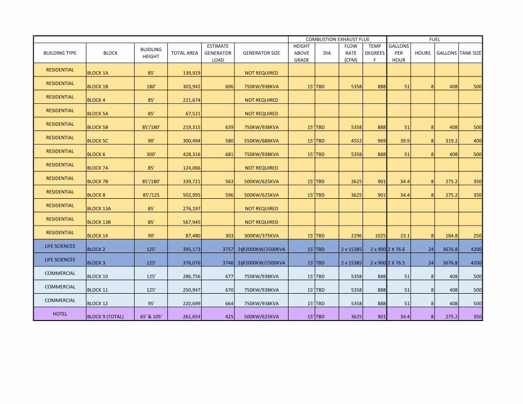
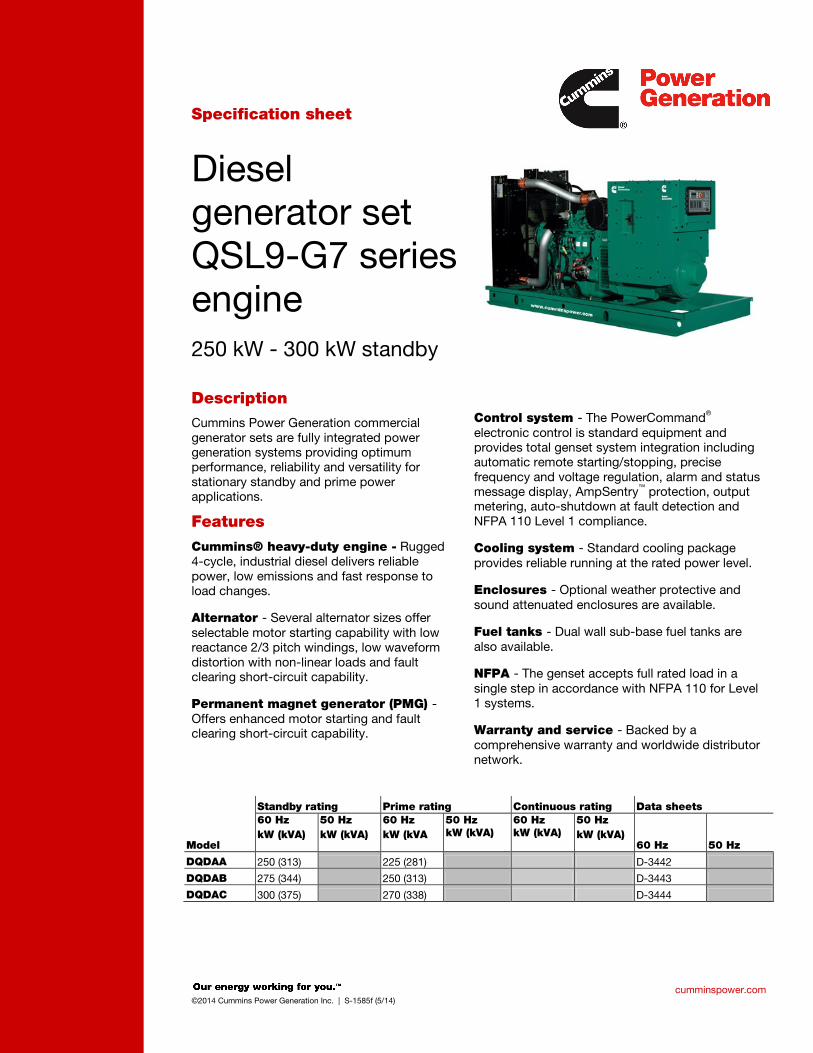
As part of the Environmental Analysis, we developed conceptual generator quantities and sizing to assist in the project environmental team. A summary of the emergency standby generator requirements for each block is included in the attached table. The generators summarized in the table are all diesel engine generator sets and operate as standby generators that operate only when utility power is not available.
Generator Testing: In addition to emergency operation when normal power is lost, generators should be tested for 30 minutes each month or 6 hours annually. An annual test where the generator is operated under load for 4 hours is also recommended. Thus, under normal conditions, each generator will operate 6-10 hours per year.
Generator Acoustic The generator sets will be attenuated to meet San Francisco’s noise ordinance which limits the generator noise level to 75dBA at the property line. Critical grade silencers and sound traps on the radiator exhaust and intake louvers may be required depending on the generator location and arrangement.
Fuel Oil Storage and Operation During Loss of Power The minimum runtime for buildings with electric fire pumps connected to the emergency generator system is 8 hours. Therefore, all fuel storage sizes are based on 8 hours except for the Life Science Buildings where life science tenants commonly request extended generator run times to support critical loads. 24 hours of storage at 50% load has been used to size the fuel oil system for the Life Science Buildings.
Generator Sizing Assumptions 1. 100% of the residential building corridor lighting will be on emergency power.2. All high-rise buildings will include stairwell pressurization fans and smoke control
fans on emergency power.3. The miscellaneous loads include fire alarm system, security system, ERRCS
system and BMS system.4. “Process” loads include grocery store refrigeration; life sciences building
laboratory exhaust and make up fans, laboratory equipment loads; commercialbuilding atrium exhaust fans.
Mr. Matt Malone MEYERS+ Ref. No.: 17.10040.00 October 27, 2017 Page 2 of 2
5. Atrium exhaust fans have also been included in the Life Science building emergency loads.
6. Two Fire Service Access Elevators plus one elevator in each bank operates on emergency power at a time. Elevator count and loads were estimated.
7. Fire pump loads were estimated based on tower height. The generator sizing is preliminary based on limited programming information. All cutsheet information is for EPA Tier 2 engine generator set. Generator Locations Assume generators are located at grade adjacent to loading areas with exhaust stacks located at 15 feet above grade and 30 feet from the property line. Please contact me if you have any additional questions: [email protected] Very truly yours,
MEYERS+ ENGINEERS
Susie See, P.E. Principal
BUILDING TYPE BLOCKBUIDLING
HEIGHTTOTAL AREA
ESTIMATE
GENERATOR
LOAD
GENERATOR SIZE
HEIGHT
ABOVE
GRADE
DIA
FLOW
RATE
(CFM)
TEMP
DEGREES
F
GALLONS
PER
HOUR
HOURS GALLONS TANK SIZE
RESIDENTIALBLOCK 1A 85' 139,929 NOT REQUIRED
RESIDENTIALBLOCK 1B 180' 303,942 606 750KW/938KVA 15' TBD 5358 888 51 8 408 500
RESIDENTIALBLOCK 4 85' 221,674 NOT REQUIRED
RESIDENTIALBLOCK 5A 85' 67,521 NOT REQUIRED
RESIDENTIALBLOCK 5B 85'/180' 219,315 639 750KW/938KVA 15' TBD 5358 888 51 8 408 500
RESIDENTIALBLOCK 5C 90' 300,494 580 550KW/688KVA 15' TBD 4552 969 39.9 8 319.2 400
RESIDENTIALBLOCK 6 300' 428,316 681 750KW/938KVA 15' TBD 5358 888 51 8 408 500
RESIDENTIALBLOCK 7A 85' 124,066 NOT REQUIRED
RESIDENTIALBLOCK 7B 85'/180' 339,721 563 500KW/625KVA 15' TBD 3625 901 34.4 8 275.2 350
RESIDENTIALBLOCK 8 85'/125 502,995 596 500KW/625KVA 15' TBD 3625 901 34.4 8 275.2 350
RESIDENTIALBLOCK 13A 85' 276,197 NOT REQUIRED
RESIDENTIALBLOCK 13B 85' 567,945 NOT REQUIRED
RESIDENTIALBLOCK 14 90' 87,480 303 300KW/375KVA 15' TBD 2296 1025 23.1 8 184.8 250
LIFE SCIENCESBLOCK 2 125' 395,173 3757 2@2000KW/2500KVA 15' TBD 2 x 15385 2 x 900 2 X 76.6 24 3676.8 4200
LIFE SCIENCESBLOCK 3 125' 376,076 3746 2@2000KW/2500KVA 15' TBD 2 x 15385 2 x 900 2 X 76.5 24 3676.8 4200
COMMERCIALBLOCK 10 125' 286,756 677 750KW/938KVA 15' TBD 5358 888 51 8 408 500
COMMERCIALBLOCK 11 125' 250,947 670 750KW/938KVA 15' TBD 5358 888 51 8 408 500
COMMERCIALBLOCK 12 95' 220,699 664 750KW/938KVA 15' TBD 5358 888 51 8 408 500
HOTELBLOCK 9 (TOTAL) 65' & 105' 261,654 425 500KW/625KVA 15' TBD 3625 901 34.4 8 275.2 350
COMBUSTION EXHAUST FLUE FUEL
cumminspower.com ©2014 Cummins Power Generation Inc. | S-1585f (5/14)
Specification sheet
Diesel generator set QSL9-G7 series engine 250 kW - 300 kW standby
Description Cummins Power Generation commercial generator sets are fully integrated power generation systems providing optimum performance, reliability and versatility for stationary standby and prime power applications.
Features
Cummins® heavy-duty engine - Rugged 4-cycle, industrial diesel delivers reliable power, low emissions and fast response to load changes.
Alternator - Several alternator sizes offer selectable motor starting capability with low reactance 2/3 pitch windings, low waveform distortion with non-linear loads and fault clearing short-circuit capability.
Permanent magnet generator (PMG) - Offers enhanced motor starting and fault clearing short-circuit capability.
Control system - The PowerCommand® electronic control is standard equipment and provides total genset system integration including automatic remote starting/stopping, precise frequency and voltage regulation, alarm and status message display, AmpSentry™ protection, output metering, auto-shutdown at fault detection and NFPA 110 Level 1 compliance.
Cooling system - Standard cooling package provides reliable running at the rated power level.
Enclosures - Optional weather protective and sound attenuated enclosures are available.
Fuel tanks - Dual wall sub-base fuel tanks are also available.
NFPA - The genset accepts full rated load in a single step in accordance with NFPA 110 for Level 1 systems.
Warranty and service - Backed by a comprehensive warranty and worldwide distributor network.
Standby rating Prime rating Continuous rating Data sheets
Model
60 Hz kW (kVA)
50 Hz kW (kVA)
60 Hz kW (kVA
50 Hz kW (kVA)
60 Hz kW (kVA)
50 Hz kW (kVA)
60 Hz 50 Hz
DQDAA 250 (313) 225 (281) D-3442
DQDAB 275 (344) 250 (313) D-3443
DQDAC 300 (375) 270 (338) D-3444
fc002
Rectangle
fc002
Line
cumminspower.com ©2014 Cummins Power Generation Inc. | S-1585f (5/14)
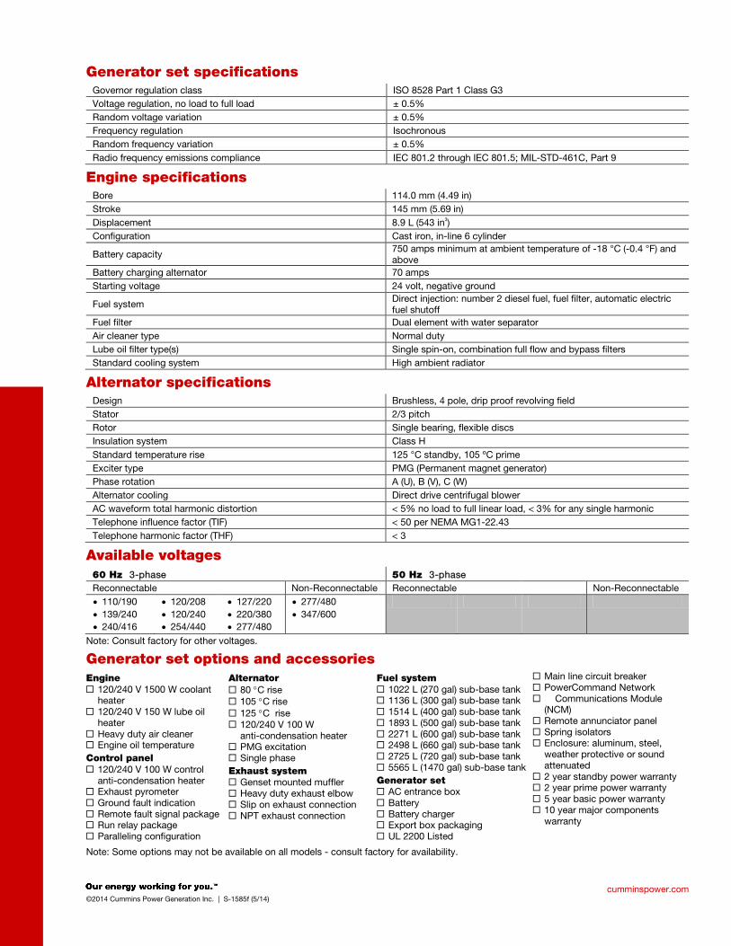
Generator set specifications Governor regulation class ISO 8528 Part 1 Class G3 Voltage regulation, no load to full load ± 0.5% Random voltage variation ± 0.5% Frequency regulation Isochronous Random frequency variation ± 0.5% Radio frequency emissions compliance IEC 801.2 through IEC 801.5; MIL-STD-461C, Part 9
Engine specifications Bore 114.0 mm (4.49 in) Stroke 145 mm (5.69 in) Displacement 8.9 L (543 in3) Configuration Cast iron, in-line 6 cylinder
Battery capacity 750 amps minimum at ambient temperature of -18 °C (-0.4 °F) and above
Battery charging alternator 70 amps Starting voltage 24 volt, negative ground
Fuel system Direct injection: number 2 diesel fuel, fuel filter, automatic electric fuel shutoff
Fuel filter Dual element with water separator Air cleaner type Normal duty Lube oil filter type(s) Single spin-on, combination full flow and bypass filters Standard cooling system High ambient radiator
Alternator specifications Design Brushless, 4 pole, drip proof revolving field Stator 2/3 pitch Rotor Single bearing, flexible discs Insulation system Class H Standard temperature rise 125 °C standby, 105 ºC prime Exciter type PMG (Permanent magnet generator) Phase rotation A (U), B (V), C (W) Alternator cooling Direct drive centrifugal blower AC waveform total harmonic distortion < 5% no load to full linear load, < 3% for any single harmonic Telephone influence factor (TIF) < 50 per NEMA MG1-22.43 Telephone harmonic factor (THF) < 3
Available voltages 60 Hz 3-phase 50 Hz 3-phase Reconnectable Non-Reconnectable Reconnectable Non-Reconnectable • 110/190 • 139/240 • 240/416
• 120/208 • 120/240 • 254/440
• 127/220 • 220/380 • 277/480
• 277/480 • 347/600
Note: Consult factory for other voltages.
Generator set options and accessories Engine 120/240 V 1500 W coolant
heater 120/240 V 150 W lube oil
heater Heavy duty air cleaner Engine oil temperature Control panel 120/240 V 100 W control
anti-condensation heater Exhaust pyrometer Ground fault indication Remote fault signal package Run relay package Paralleling configuration
Alternator 80 °C rise 105 °C rise 125 °C rise 120/240 V 100 W
anti-condensation heater PMG excitation Single phase Exhaust system Genset mounted muffler Heavy duty exhaust elbow Slip on exhaust connection NPT exhaust connection
Fuel system 1022 L (270 gal) sub-base tank 1136 L (300 gal) sub-base tank 1514 L (400 gal) sub-base tank 1893 L (500 gal) sub-base tank 2271 L (600 gal) sub-base tank 2498 L (660 gal) sub-base tank 2725 L (720 gal) sub-base tank 5565 L (1470 gal) sub-base tank Generator set AC entrance box Battery Battery charger Export box packaging UL 2200 Listed
Main line circuit breaker PowerCommand Network Communications Module
(NCM) Remote annunciator panel Spring isolators Enclosure: aluminum, steel,
weather protective or sound attenuated
2 year standby power warranty 2 year prime power warranty 5 year basic power warranty 10 year major components
warranty
Note: Some options may not be available on all models - consult factory for availability.
cumminspower.com ©2014 Cummins Power Generation Inc. | S-1585f (5/14)
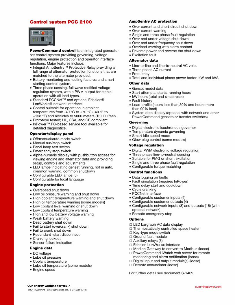
Control system PCC 2100
PowerCommand control is an integrated generator set control system providing governing, voltage regulation, engine protection and operator interface functions. Major features include: • Integral AmpSentry™ Protective Relay providing a
full range of alternator protection functions that are matched to the alternator provided.
• Battery monitoring and testing features and smart starting control system.
• Three phase sensing, full wave rectified voltage regulation system, with a PWM output for stable operation with all load types.
• Standard PCCNet™ and optional Echelon® LonWorks® network interface.
• Control suitable for operation in ambient temperatures from -40 °C to +70 °C (-40 °F to +158 °F) and altitudes to 5000 meters (13,000 feet).
• Prototype tested; UL, CSA, and CE compliant. • InPower™ PC-based service tool available for
detailed diagnostics.
Operator/display panel • Off/manual/auto mode switch • Manual run/stop switch • Panel lamp test switch • Emergency stop switch • Alpha-numeric display with pushbutton access for
viewing engine and alternator data and providing setup, controls and adjustments
• LED lamps indicating genset running, not in auto, common warning, common shutdown
• Configurable LED lamps (5) • Configurable for local language
Engine protection • Overspeed shut down • Low oil pressure warning and shut down • High coolant temperature warning and shut down • High oil temperature warning (some models) • Low coolant level warning or shut down • Low coolant temperature warning • High and low battery voltage warning • Weak battery warning • Dead battery shut down • Fail to start (overcrank) shut down • Fail to crank shut down • Redundant -start disconnect • Cranking lockout • Sensor failure indication
Engine data • DC voltage • Lube oil pressure • Coolant temperature • Lube oil temperature (some models) • Engine speed
AmpSentry AC protection • Over current and short-circuit shut down • Over current warning • Single and three phase fault regulation • Over and under voltage shut down • Over and under frequency shut down • Overload warning with alarm contact • Reverse power and reverse Var shut down • Excitation fault
Alternator data • Line-to-line and line-to-neutral AC volts • Three phase AC current • Frequency • Total and individual phase power factor, kW and kVA
Other data • Genset model data • Start attempts, starts, running hours • kW hours (total and since reset) • Fault history • Load profile (hours less than 30% and hours more
than 90% load) • System data display (optional with network and other
PowerCommand gensets or transfer switches)
Governing • Digital electronic isochronous governor • Temperature dynamic governing • Smart idle speed mode • Glow plug control (some models)
Voltage regulation • Digital PWM electronic voltage regulation • Three phase line-to-neutral sensing • Suitable for PMG or shunt excitation • Single and three phase fault regulation • Configurable torque matching
Control functions • Data logging on faults • Fault simulation (requires InPower) • Time delay start and cooldown • Cycle cranking • PCCNet interface • Configurable customer inputs (4) • Configurable customer outputs (4) • Configurable network inputs (8) and outputs (16) (with
optional network) • Remote emergency stop
Options LED bargraph AC data display Thermostatically controlled space heater Key-type mode switch Ground fault module Auxiliary relays (3) Echelon LONWORKS interface Modlon Gateway to convert to Modbus (loose) PowerCommand iWatch web server for remote
monitoring and alarm notification (loose) Digital input and output module(s) (loose) Remote annunciator (loose)
For further detail see document S-1409.
North America 1400 73rd Avenue N.E. Minneapolis, MN 55432 USA Phone 763 574 5000 Fax 763 574 5298 ©2014 Cummins Power Generation Inc. All rights reserved. Cummins Power Generation and Cummins are registered trademarks of Cummins Inc. PowerCommand, AmpSentry, InPower and “Our energy working for you.” are trademarks of Cummins Power Generation. Other company, product, or service names may be trademarks or service marks of others. Specifications are subject to change without notice.
S-1585f (5/14)
cumminspower.com
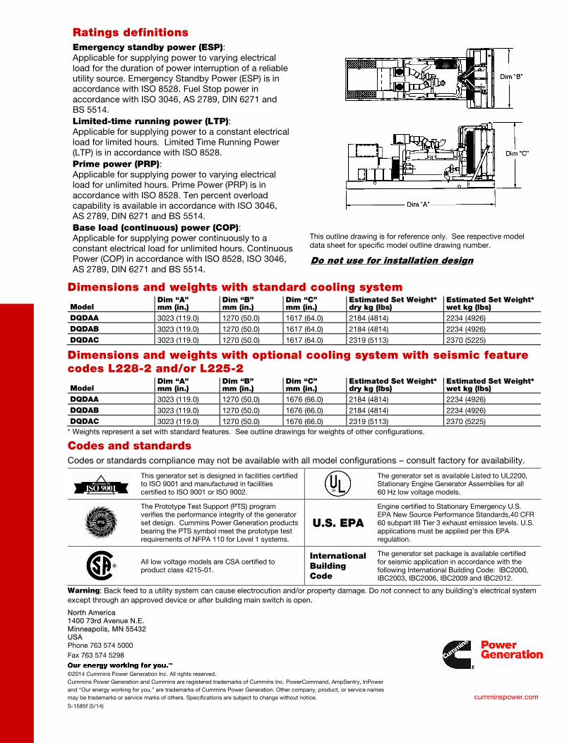
Dimensions and weights with standard cooling system
Model Dim “A” mm (in.)
Dim “B” mm (in.)
Dim “C” mm (in.)
Estimated Set Weight* dry kg (lbs)
Estimated Set Weight* wet kg (lbs)
DQDAA 3023 (119.0) 1270 (50.0) 1617 (64.0) 2184 (4814) 2234 (4926) DQDAB 3023 (119.0) 1270 (50.0) 1617 (64.0) 2184 (4814) 2234 (4926) DQDAC 3023 (119.0) 1270 (50.0) 1617 (64.0) 2319 (5113) 2370 (5225)
Dimensions and weights with optional cooling system with seismic feature codes L228-2 and/or L225-2
Model Dim “A” mm (in.)
Dim “B” mm (in.)
Dim “C” mm (in.)
Estimated Set Weight* dry kg (lbs)
Estimated Set Weight* wet kg (lbs)
DQDAA 3023 (119.0) 1270 (50.0) 1676 (66.0) 2184 (4814) 2234 (4926) DQDAB 3023 (119.0) 1270 (50.0) 1676 (66.0) 2184 (4814) 2234 (4926) DQDAC 3023 (119.0) 1270 (50.0) 1676 (66.0) 2319 (5113) 2370 (5225)
* Weights represent a set with standard features. See outline drawings for weights of other configurations.
Codes and standards Codes or standards compliance may not be available with all model configurations – consult factory for availability.
This generator set is designed in facilities certified to ISO 9001 and manufactured in facilities certified to ISO 9001 or ISO 9002.
The generator set is available Listed to UL2200, Stationary Engine Generator Assemblies for all 60 Hz low voltage models.
The Prototype Test Support (PTS) program verifies the performance integrity of the generator set design. Cummins Power Generation products bearing the PTS symbol meet the prototype test requirements of NFPA 110 for Level 1 systems.
U.S. EPA
Engine certified to Stationary Emergency U.S. EPA New Source Performance Standards,40 CFR 60 subpart IIII Tier 3 exhaust emission levels. U.S. applications must be applied per this EPA regulation.
All low voltage models are CSA certified to product class 4215-01.
International Building Code
The generator set package is available certified for seismic application in accordance with the following International Building Code: IBC2000, IBC2003, IBC2006, IBC2009 and IBC2012.
Warning: Back feed to a utility system can cause electrocution and/or property damage. Do not connect to any building’s electrical system except through an approved device or after building main switch is open.
Ratings definitions
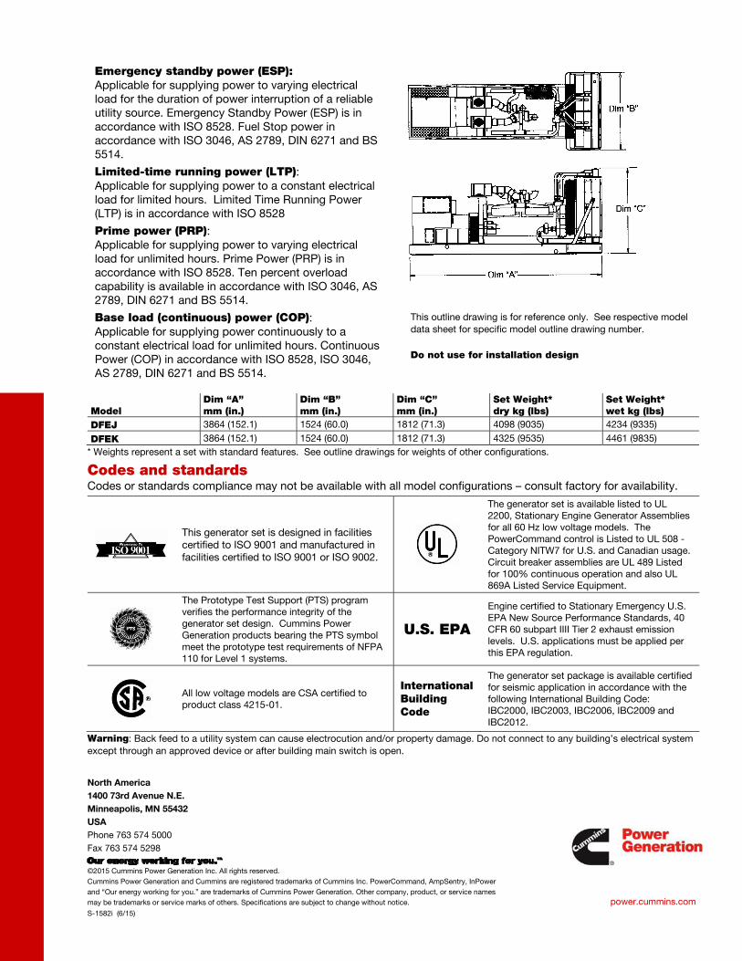
Emergency standby power (ESP): Applicable for supplying power to varying electrical load for the duration of power interruption of a reliable utility source. Emergency Standby Power (ESP) is in accordance with ISO 8528. Fuel Stop power in accordance with ISO 3046, AS 2789, DIN 6271 and BS 5514. Limited-time running power (LTP): Applicable for supplying power to a constant electrical load for limited hours. Limited Time Running Power (LTP) is in accordance with ISO 8528. Prime power (PRP): Applicable for supplying power to varying electrical load for unlimited hours. Prime Power (PRP) is in accordance with ISO 8528. Ten percent overload capability is available in accordance with ISO 3046, AS 2789, DIN 6271 and BS 5514. Base load (continuous) power (COP): Applicable for supplying power continuously to a constant electrical load for unlimited hours. Continuous Power (COP) in accordance with ISO 8528, ISO 3046, AS 2789, DIN 6271 and BS 5514.
This outline drawing is for reference only. See respective model data sheet for specific model outline drawing number.
Do not use for installation design
fc002
Rectangle
fc002
Line
fc002
Rectangle
fc002
Line
cumminspower.com ©2014 Cummins Power Generation Inc. | D-3444f (11/14)
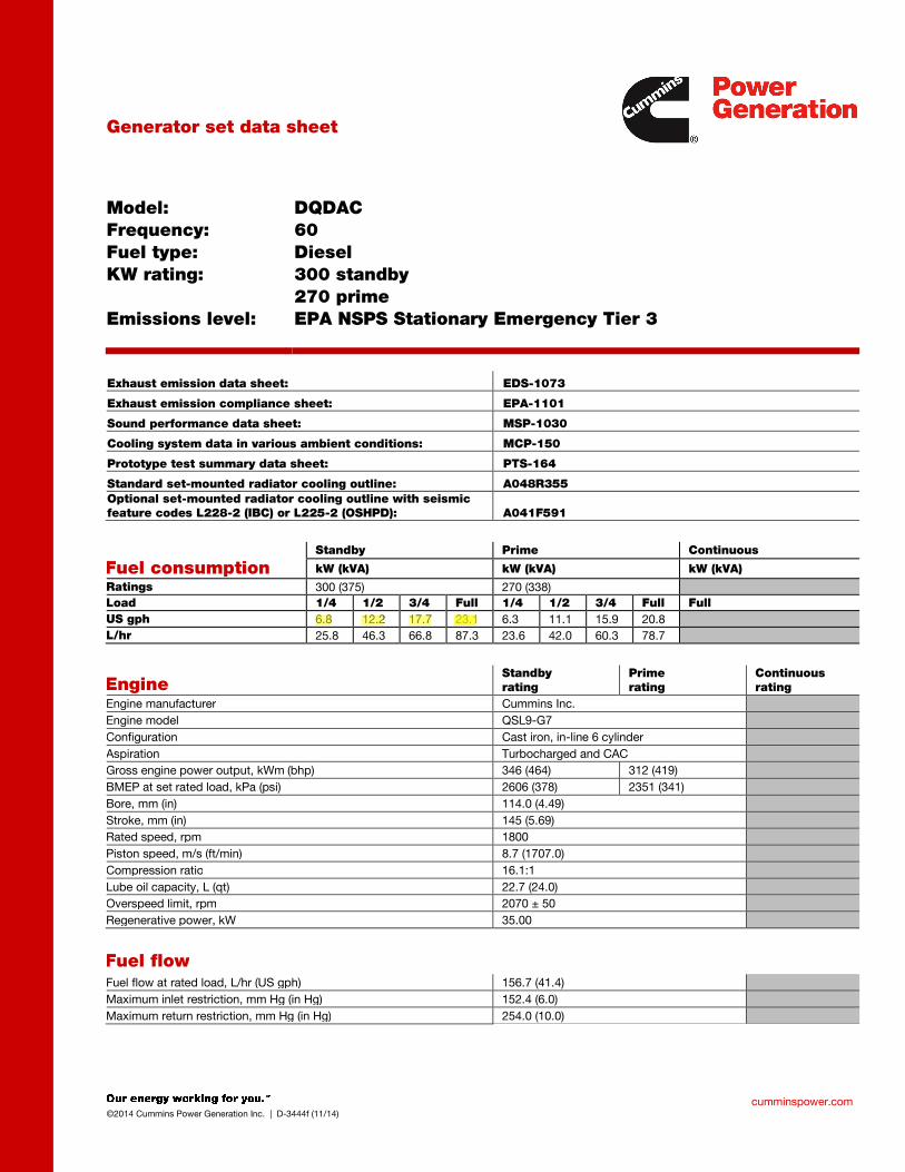
Generator set data sheet
Model:
Frequency:
Fuel type:
KW rating:
Emissions level:
DQDAC
60
Diesel
300 standby
270 prime
EPA NSPS Stationary Emergency Tier 3
Exhaust emission data sheet: EDS-1073
Exhaust emission compliance sheet: EPA-1101
Sound performance data sheet: MSP-1030
Cooling system data in various ambient conditions: MCP-150
Prototype test summary data sheet: PTS-164
Standard set-mounted radiator cooling outline: A048R355
Optional set-mounted radiator cooling outline with seismic
feature codes L228-2 (IBC) or L225-2 (OSHPD): A041F591
Fuel consumption Standby Prime Continuous
kW (kVA) kW (kVA) kW (kVA)
Ratings 300 (375) 270 (338)
Load 1/4 1/2 3/4 Full 1/4 1/2 3/4 Full Full
US gph 6.8 12.2 17.7 23.1 6.3 11.1 15.9 20.8
L/hr 25.8 46.3 66.8 87.3 23.6 42.0 60.3 78.7
Engine Standby
rating
Prime
rating
Continuous
rating
Engine manufacturer Cummins Inc.
Engine model QSL9-G7
Configuration Cast iron, in-line 6 cylinder
Aspiration Turbocharged and CAC
Gross engine power output, kWm (bhp) 346 (464) 312 (419)
BMEP at set rated load, kPa (psi) 2606 (378) 2351 (341)
Bore, mm (in) 114.0 (4.49)
Stroke, mm (in) 145 (5.69)
Rated speed, rpm 1800
Piston speed, m/s (ft/min) 8.7 (1707.0)
Compression ratio 16.1:1
Lube oil capacity, L (qt) 22.7 (24.0)
Overspeed limit, rpm 2070 ± 50
Regenerative power, kW 35.00
Fuel flow Fuel flow at rated load, L/hr (US gph) 156.7 (41.4)
Maximum inlet restriction, mm Hg (in Hg) 152.4 (6.0)
Maximum return restriction, mm Hg (in Hg) 254.0 (10.0)
fc002
Rectangle
fc002
Highlight
fc002
Line
fc002
Highlight
fc002
Rectangle
cumminspower.com ©2014 Cummins Power Generation Inc. | D-3444f (11/14)
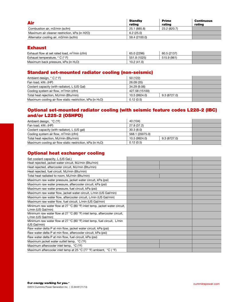
Air Standby
rating
Prime
rating
Continuous
rating
Combustion air, m3/min (scfm) 25.1 (885.8) 23.2 (820.7)
Maximum air cleaner restriction, kPa (in H2O) 6.2 (25.0)
Alternator cooling air, m3/min (scfm) 59.4 (2100.0)
Exhaust
Exhaust flow at set rated load, m3/min (cfm) 65.0 (2296) 60.5 (2137)
Exhaust temperature, ° C (° F) 551.8 (1025) 515.9 (961)
Maximum back pressure, kPa (in H2O) 10.2 (41.0)
Standard set-mounted radiator cooling (non-seismic) Ambient design, ° C (° F) 50 (122)
Fan load, kWm (HP) 26.09 (35)
Coolant capacity (with radiator), L (US Gal) 34.29 (9.06)
Cooling system air flow, m3/min (cfm) 427.58 (15100)
Total heat rejection, MJ/min (Btu/min) 10.5 (9924.0) 9.3 (8727.0)
Maximum cooling air flow static restriction, kPa (in H2O) 0.12 (0.5)
Optional set-mounted radiator cooling (with seismic feature codes L228-2 (IBC)
and/or L225-2 (OSHPD)
Ambient design, °C (°F) 40 (104)
Fan load, kWm (HP) 27.8 (37.2)
Coolant capacity (with radiator), L (US gal) 30.3 (8.0)
Cooling system air flow, m3/min (cfm) 568.1 (20075.0)
Total heat rejection, MJ/min (Btu/min) 10.5 (9924.0) 9.3 (8727.0)
Maximum cooling air flow static restriction, kPa (in H2O) 0.12 (0.5)
Optional heat exchanger cooling
Set coolant capacity, L (US Gal.)
Heat rejected, jacket water circuit, MJ/min (Btu/min)
Heat rejected, aftercooler circuit, MJ/min (Btu/min)
Heat rejected, fuel circuit, MJ/min (Btu/min)
Total heat radiated to room, MJ/min (Btu/min)
Maximum raw water pressure, jacket water circuit, kPa (psi)
Maximum raw water pressure, aftercooler circuit, kPa (psi)
Maximum raw water pressure, fuel circuit, kPa (psi)
Maximum raw water flow, jacket water circuit, L/min (US Gal/min)
Maximum raw water flow, aftercooler circuit, L/min (US Gal/min)
Maximum raw water flow, fuel circuit, L/min (US Gal/min)
Minimum raw water flow at 27 °C (80 °F) inlet temp, jacket water circuit, L/min (US Gal/min)
Minimum raw water flow at 27 °C (80 °F) inlet temp, aftercooler circuit, L/min (US Gal/min)
Minimum raw water flow at 27 °C (80 °F) inlet temp, fuel circuit, L/min (US Gal/min)
Raw water delta P at min flow, jacket water circuit, kPa (psi)
Raw water delta P at min flow, aftercooler circuit, kPa (psi)
Raw water delta P at min flow, fuel circuit, kPa (psi)
Maximum jacket water outlet temp, °C (°F)
Maximum aftercooler inlet temp, °C (°F)
Maximum aftercooler inlet temp at 25 °C (77 °F) ambient, °C ( °F)
fc002
Rectangle
fc002
Rectangle
fc002
Rectangle
fc002
Rectangle
cumminspower.com ©2014 Cummins Power Generation Inc. | D-3444f (11/14)
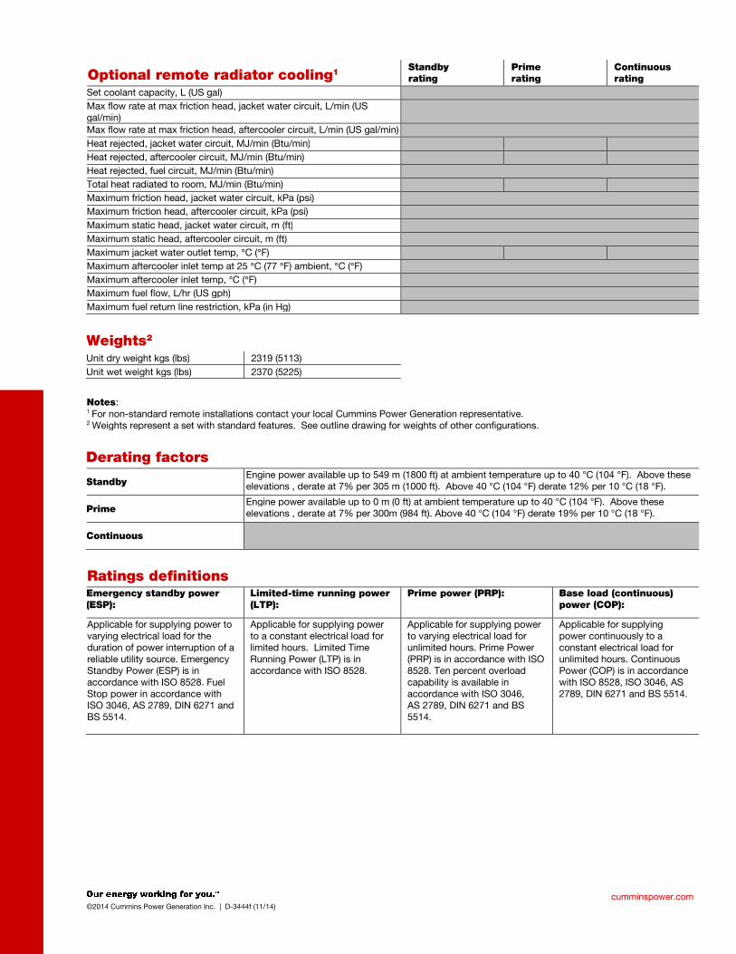
Optional remote radiator cooling1 Standby
rating
Prime
rating
Continuous
rating
Set coolant capacity, L (US gal)
Max flow rate at max friction head, jacket water circuit, L/min (US gal/min)
Max flow rate at max friction head, aftercooler circuit, L/min (US gal/min)
Heat rejected, jacket water circuit, MJ/min (Btu/min)
Heat rejected, aftercooler circuit, MJ/min (Btu/min)
Heat rejected, fuel circuit, MJ/min (Btu/min)
Total heat radiated to room, MJ/min (Btu/min)
Maximum friction head, jacket water circuit, kPa (psi)
Maximum friction head, aftercooler circuit, kPa (psi)
Maximum static head, jacket water circuit, m (ft)
Maximum static head, aftercooler circuit, m (ft)
Maximum jacket water outlet temp, °C (°F)
Maximum aftercooler inlet temp at 25 °C (77 °F) ambient, °C (°F)
Maximum aftercooler inlet temp, °C (°F)
Maximum fuel flow, L/hr (US gph)
Maximum fuel return line restriction, kPa (in Hg)
Weights2
Unit dry weight kgs (lbs) 2319 (5113)
Unit wet weight kgs (lbs) 2370 (5225)
Notes: 1 For non-standard remote installations contact your local Cummins Power Generation representative. 2 Weights represent a set with standard features. See outline drawing for weights of other configurations.
Derating factors
Standby Engine power available up to 549 m (1800 ft) at ambient temperature up to 40 °C (104 °F). Above these elevations , derate at 7% per 305 m (1000 ft). Above 40 °C (104 °F) derate 12% per 10 °C (18 °F).
Prime Engine power available up to 0 m (0 ft) at ambient temperature up to 40 °C (104 °F). Above these elevations , derate at 7% per 300m (984 ft). Above 40 °C (104 °F) derate 19% per 10 °C (18 °F).
Continuous
Ratings definitions
Emergency standby power
(ESP):
Limited-time running power
(LTP):
Prime power (PRP): Base load (continuous)
power (COP):
Applicable for supplying power to varying electrical load for the duration of power interruption of a reliable utility source. Emergency Standby Power (ESP) is in accordance with ISO 8528. Fuel Stop power in accordance with ISO 3046, AS 2789, DIN 6271 and BS 5514.
Applicable for supplying power to a constant electrical load for limited hours. Limited Time Running Power (LTP) is in accordance with ISO 8528.
Applicable for supplying power to varying electrical load for unlimited hours. Prime Power (PRP) is in accordance with ISO 8528. Ten percent overload capability is available in accordance with ISO 3046, AS 2789, DIN 6271 and BS 5514.
Applicable for supplying power continuously to a constant electrical load for unlimited hours. Continuous Power (COP) is in accordance with ISO 8528, ISO 3046, AS 2789, DIN 6271 and BS 5514.
North America
1400 73rd Avenue N.E.
Minneapolis, MN 55432
USA
Phone 763 574 5000
Fax 763 574 5298
©2014 Cummins Power Generation Inc. All rights reserved.
Cummins Power Generation and Cummins are registered trademarks of Cummins Inc. PowerCommand, AmpSentry, InPower
and “Our energy working for you.” are trademarks of Cummins Power Generation. Other company, product, or service names
may be trademarks or service marks of others. Specifications are subject to change without notice.
D-3444f (11/14)
cumminspower.com
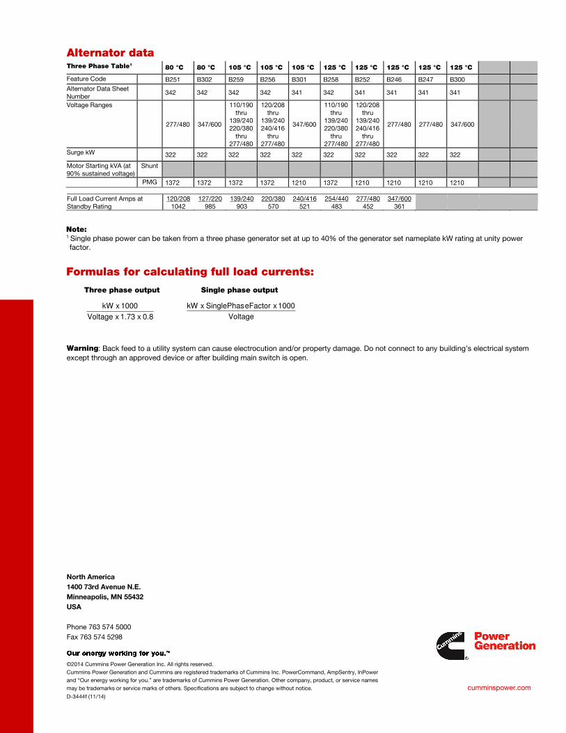
Alternator data Three Phase Table1 80 °C 80 °C 105 °C 105 °C 105 °C 125 °C 125 °C 125 °C 125 °C 125 °C
Feature Code B251 B302 B259 B256 B301 B258 B252 B246 B247 B300
Alternator Data Sheet Number
342 342 342 342 341 342 341 341 341 341
Voltage Ranges
277/480 347/600
110/190 thru
139/240 220/380
thru 277/480
120/208 thru
139/240 240/416
thru 277/480
347/600
110/190 thru
139/240 220/380
thru 277/480
120/208 thru
139/240 240/416
thru 277/480
277/480 277/480 347/600
Surge kW 322 322 322 322 322 322 322 322 322 322 Motor Starting kVA (at 90% sustained voltage)
Shunt
PMG 1372 1372 1372 1372 1210 1372 1210 1210 1210 1210
Full Load Current Amps at Standby Rating
120/208 1042
127/220 985
139/240 903
220/380 570
240/416 521
254/440 483
277/480 452
347/600 361
Note: 1 Single phase power can be taken from a three phase generator set at up to 40% of the generator set nameplate kW rating at unity power factor.
Formulas for calculating full load currents:
Three phase output Single phase output
Warning: Back feed to a utility system can cause electrocution and/or property damage. Do not connect to any building’s electrical system
except through an approved device or after building main switch is open.
Voltage
1000 x eFactorSinglePhas x kW
0.8 x 1.73 x Voltage
1000 x kW

Our energy working for you.™
www.cumminspower.com 2014 Cummins Power Generation Inc. All rights reserved. Cummins Power Generation and Cummins are registered trademarks of Cummins Inc. PowerCommand and “Our energy working for you.” are trademarks of Cummins Power Generation. Specifications are subject to change without notice. S-1443z (9/14)
Enclosures and tanks 250-1000 kW gensets
Enclosure standard features • 14-gauge steel construction (panels) • Stainless steel hardware • Zinc phosphate pretreatment, e-coat primer and super
durable powder topcoat paint minimize corrosion and color fade
• Package listed to UL 2200 • Designed to satisfy National Electrical Code installation
requirements • Fuel and electrical stub-up area within enclosure
perimeter • Fixed louvers • Cambered roof prevents water accumulation • Recessed, lockable doors in two sides • Retainers hold doors open for easy access • Enclosed exhaust silencer ensures safety and protects
against rust • Rain cap • Exterior oil and coolant drains with interior valves for
ease of service • Rodent barriers on inlet • Non-hydroscopic sound attenuating material • Side mounted controls and circuit breakers • Easy access lifting points for spreader bars • Dual vibration isolation system (250-500 kW) • Spring vibration isolation system (600-1000 kW) • Enclosure mounts to lifting base or fuel tank
(250-500 kW) • Enclosure mounts to lifting base (600-1000 kW) • Factory pre-assembled package • Designed for outdoor use only • Externally mounted emergency stop button for
operator safety (optional on 250-500 kW) • Horizontal air discharge to prevent leaf and snow
accumulation (600-1000 kW)
Options • Three levels of sound attenuation • Motorized louvers to protect from ice and snow
accumulation (available on air inlet for all models and on air outlet on level II, 250-500 kW enclosures only)
• Horizontal air discharge, sound level 2 only (250-500 kW)
• Aluminum construction with roll-coated polymer paint • Wind rated to 150 mph • Neutral sandstone paint color • Factory mounted battery charger • External 120 VAC service outlet • Rain hoods for air inlet (250-500 kW) • Lifting base in lieu of a sub-base tank (250-500 kW)
- Pre-wired AC distribution package - 100 amp (250-500 kW) or 150 amp (600-1000 kW)
main circuit breaker; connected to 120 VAC line-neutral and 208 or 240 VAC line-line, spare breaker positions and capacity for future upgrades (600-1000 kW)
- GFCI protected internal 120 VAC service receptacle - GFCI protected weather proof external 120 volt
service receptacle - All factory installed AC powered features pre-wired
into load center • Interior lights – 120 volt (600-1000 kW) • Rain hoods for air inlet (250-500 kW) • Seismic isolators available (600-1000 kW)
Our energy working for you.™
www.cumminspower.com 2014 Cummins Power Generation Inc. All rights reserved. Cummins Power Generation and Cummins are registered trademarks of Cummins Inc. PowerCommand and “Our energy working for you.” are trademarks of Cummins Power Generation. Specifications are subject to change without notice. S-1443z (9/14)
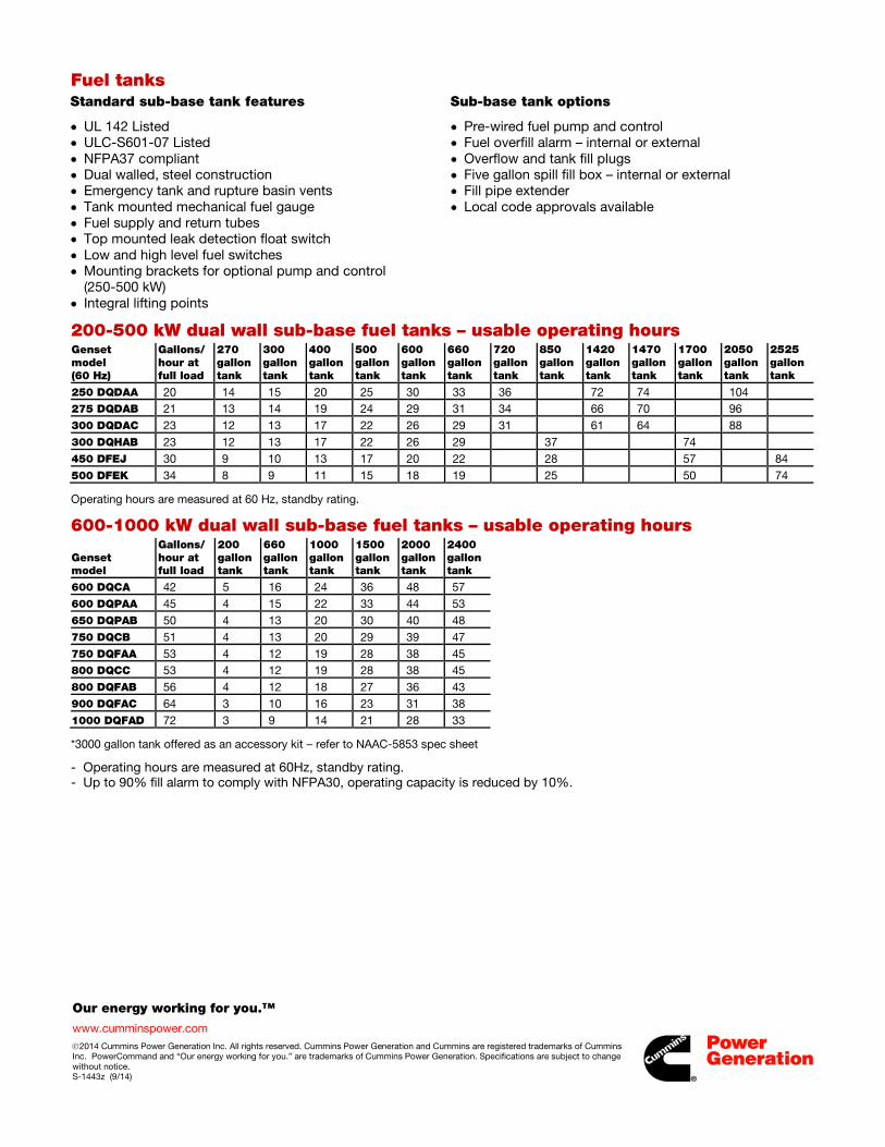
Fuel tanks Standard sub-base tank features
• UL 142 Listed • ULC-S601-07 Listed • NFPA37 compliant • Dual walled, steel construction • Emergency tank and rupture basin vents • Tank mounted mechanical fuel gauge • Fuel supply and return tubes • Top mounted leak detection float switch • Low and high level fuel switches • Mounting brackets for optional pump and control
(250-500 kW) • Integral lifting points
Sub-base tank options
• Pre-wired fuel pump and control • Fuel overfill alarm – internal or external • Overflow and tank fill plugs • Five gallon spill fill box – internal or external • Fill pipe extender • Local code approvals available
200-500 kW dual wall sub-base fuel tanks – usable operating hours Genset model (60 Hz)
Gallons/hour at full load
270 gallon tank
300 gallon tank
400 gallon tank
500 gallon tank
600 gallon tank
660 gallon tank
720 gallon tank
850 gallon tank
1420 gallon tank
1470 gallon tank
1700 gallon tank
2050 gallon tank
2525 gallon tank
250 DQDAA 20 14 15 20 25 30 33 36 72 74 104 275 DQDAB 21 13 14 19 24 29 31 34 66 70 96 300 DQDAC 23 12 13 17 22 26 29 31 61 64 88 300 DQHAB 23 12 13 17 22 26 29 37 74 450 DFEJ 30 9 10 13 17 20 22 28 57 84 500 DFEK 34 8 9 11 15 18 19 25 50 74
Operating hours are measured at 60 Hz, standby rating.
600-1000 kW dual wall sub-base fuel tanks – usable operating hours
Genset model
Gallons/hour at full load
200 gallon tank
660 gallon tank
1000 gallon tank
1500 gallon tank
2000 gallon tank
2400 gallon tank
600 DQCA 42 5 16 24 36 48 57 600 DQPAA 45 4 15 22 33 44 53 650 DQPAB 50 4 13 20 30 40 48 750 DQCB 51 4 13 20 29 39 47 750 DQFAA 53 4 12 19 28 38 45 800 DQCC 53 4 12 19 28 38 45 800 DQFAB 56 4 12 18 27 36 43 900 DQFAC 64 3 10 16 23 31 38 1000 DQFAD 72 3 9 14 21 28 33
*3000 gallon tank offered as an accessory kit – refer to NAAC-5853 spec sheet
- Operating hours are measured at 60Hz, standby rating. - Up to 90% fill alarm to comply with NFPA30, operating capacity is reduced by 10%.
fc002
Rectangle
fc002
Line

.
Our energy working for you.™
www.cumminspower.com 2014 Cummins Power Generation Inc. All rights reserved. Cummins Power Generation and Cummins are registered trademarks of Cummins Inc. PowerCommand and “Our energy working for you.” are trademarks of Cummins Power Generation. Specifications are subject to change without notice. S-1443z (9/14)
Enclosure package sound pressure levels @ 7 meters dB(A)
Genset model
Weather protective enclosure (F200, F203)
QuietSite Level 1 sound attenuated enclosure (F201, F204)
QuietSite Level 2 sound attenuated enclosure (F202, F205)
250 DQDAA 90 88 72 275 DQDAB 90 88 73 300 DQDAC 90 88 73 300 DQHAB 89 88 76 450 DFEJ 88 85 74 500 DFEK 89 87 73 600 DQCA 86/86* 82/78* 74/73* 600 DQPAA 89 81 77 650 DQPAB 90 81 80 750 DQCB 88/87* 83/79* 75/74* 750 DQFAA 89 79 75 800 DQCC 88/87* 83/79* 75/74* 800 DQFAB 89 79 75 900 DQFAC 89 80 76 1000 DQFAD 90 80 76
- All data is 60Hz, full load standby rating, steel enclosures only. - Data is a measured average of 8 positions. - Sound levels for aluminum enclosures are approximately 2 dB(A) higher than listed sound levels for steel enclosures. * Sound data with seismic feature codes L228-2 (IBC) and/or L225-2 (OSHPD)
Package dimensions of enclosure, exhaust system, and UL tank 250-500 kW
Tank size (gal)
Weather protective package length (in)
QuietSite level I package length (in)
QuietSite level 2 package length (in)
Width (in)
Height (in)
Weather protective package weight (lbs)
QuietSite level 1 package weight (lbs)
QuietSite level 2 package weight (lbs)
270 188 188 222 82 106 4991 5471 6711 300 188 188 222 82 104 5648 6073 6991 400 188 188 222 82 106 5833 6258 7176 500 188 188 222 82 108 5956 6381 7299 600 188 188 222 82 111 6116 6541 7459 660 188 188 222 82 113 6235 6660 7578 720 188 188 222 82 114 6174 6599 7517 850 188 188 222 82 118 6529 6954 7872 1420 200 200 222 82 128 6863 7343 8583 1470 192 192 222 82 128 7253 7733 8973 1700 234 234 234 82 128 7982 8407 9325 2050 284 284 284 82 128 8383 8863 10103 2525 346 346 346 82 128 9391 9871 11111 Lifting base 188 188 222 82 100 4335 4760 5678
600-1000 kW
Tank size (gal)
Weather Protective package length (in)
QuietSite level I package length (in)
QuietSite level 2 package length (in)
Width (in)
Height (in)
Weather protective package weight (lbs)
QuietSite level 1 package weight (lbs)
QuietSite level 2 package weight (lbs)
200 260 303 315 98 137 10194 13074 14954 660 260 303 315 98 137 9586 12466 14346 1000 260 303 315 98 141 10117 12997 14877 1500 260 303 315 98 146 10677 13557 15437 2000 292 327 327 98 143 11959 14839 16719 2400 338 338 338 98 143 12961 15841 17721
- This weight does not include the generator set. Consult your local Cummins Power Generation distributor or the appropriate generator specification sheet.
- Width is 86” lifting eye to lifting eye (250-500 kW), 102” lifting eye to lifting eye (600-1000 kW). - Height - Florida, Michigan, and Suffolk add 4” (250-500 kW) or 2” (600-1000 kW) for bottom space. - Maximum length emergency vent removed.
fc002
Rectangle
fc002
Line
fc002
Rectangle
fc002
Line

.
Our energy working for you.™
www.cumminspower.com 2014 Cummins Power Generation Inc. All rights reserved. Cummins Power Generation and Cummins are registered trademarks of Cummins Inc. PowerCommand and “Our energy working for you.” are trademarks of Cummins Power Generation. Specifications are subject to change without notice. S-1443z (9/14)
CSA - The generator set is CSA certified to product class 4215-01.
UL - The generator set is available Listed to UL 2200, Stationary Engine Generator Assemblies. The PowerCommand control is Listed to UL 508 - Category NITW7 for U.S. and Canadian usage.
See your distributor for more information Americas 1400 73rd Avenue N.E. Minneapolis, MN 55432 USA Phone: 763 574-5000 Fax: 763 574-5298
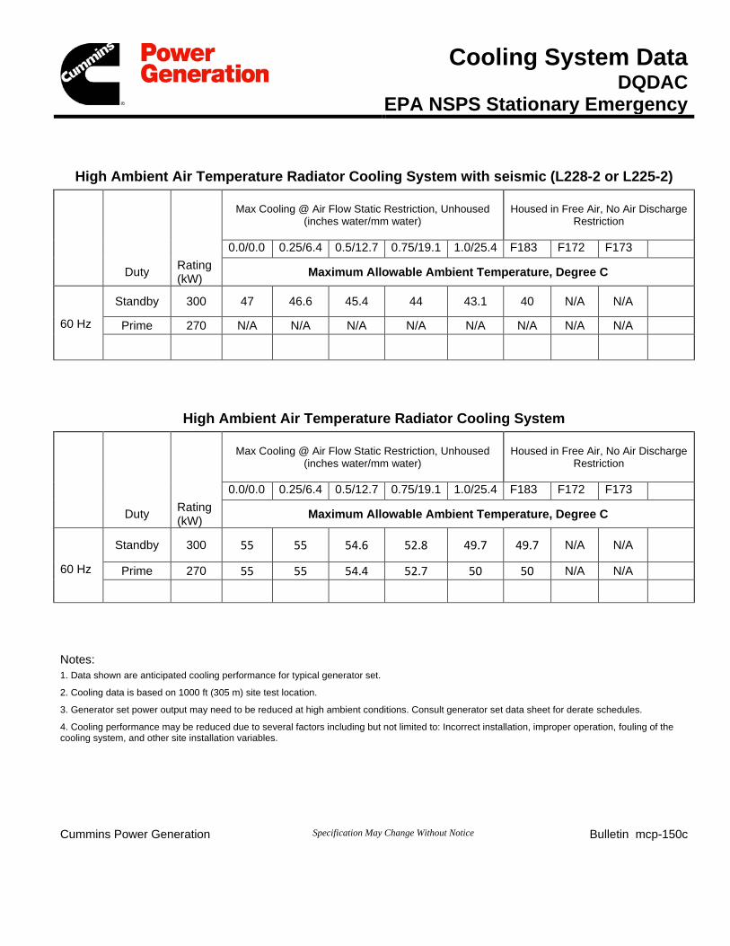
Cooling System Data DQDAC
EPA NSPS Stationary Emergency
High Ambient Air Temperature Radiator Cooling System with seismic (L228-2 or L225-2)
Max Cooling @ Air Flow Static Restriction, Unhoused (inches water/mm water)
Housed in Free Air, No Air Discharge Restriction
0.0/0.0 0.25/6.4 0.5/12.7 0.75/19.1 1.0/25.4 F183 F172 F173 Duty Rating
(kW) Maximum Allowable Ambient Temperature, Degree C Standby 300 47 46.6 45.4 44 43.1 40 N/A N/A
60 Hz Prime 270 N/A N/A N/A N/A N/A N/A N/A N/A
High Ambient Air Temperature Radiator Cooling System
Max Cooling @ Air Flow Static Restriction, Unhoused (inches water/mm water)
Housed in Free Air, No Air Discharge Restriction
0.0/0.0 0.25/6.4 0.5/12.7 0.75/19.1 1.0/25.4 F183 F172 F173 Duty Rating
(kW) Maximum Allowable Ambient Temperature, Degree C
Standby 300 55 55 54.6 52.8 49.7 49.7 N/A N/A
60 Hz Prime 270 55 55 54.4 52.7 50 50 N/A N/A
Notes: 1. Data shown are anticipated cooling performance for typical generator set.
2. Cooling data is based on 1000 ft (305 m) site test location.
3. Generator set power output may need to be reduced at high ambient conditions. Consult generator set data sheet for derate schedules.
4. Cooling performance may be reduced due to several factors including but not limited to: Incorrect installation, improper operation, fouling of the cooling system, and other site installation variables.
Cummins Power Generation Specification May Change Without Notice Bulletin mcp-150c
fc002
Rectangle
fc002
Rectangle
fc002
Line
fc002
Line
power.cummins.com ©2015 Cummins Power Generation Inc. | S-1582i (6/15)
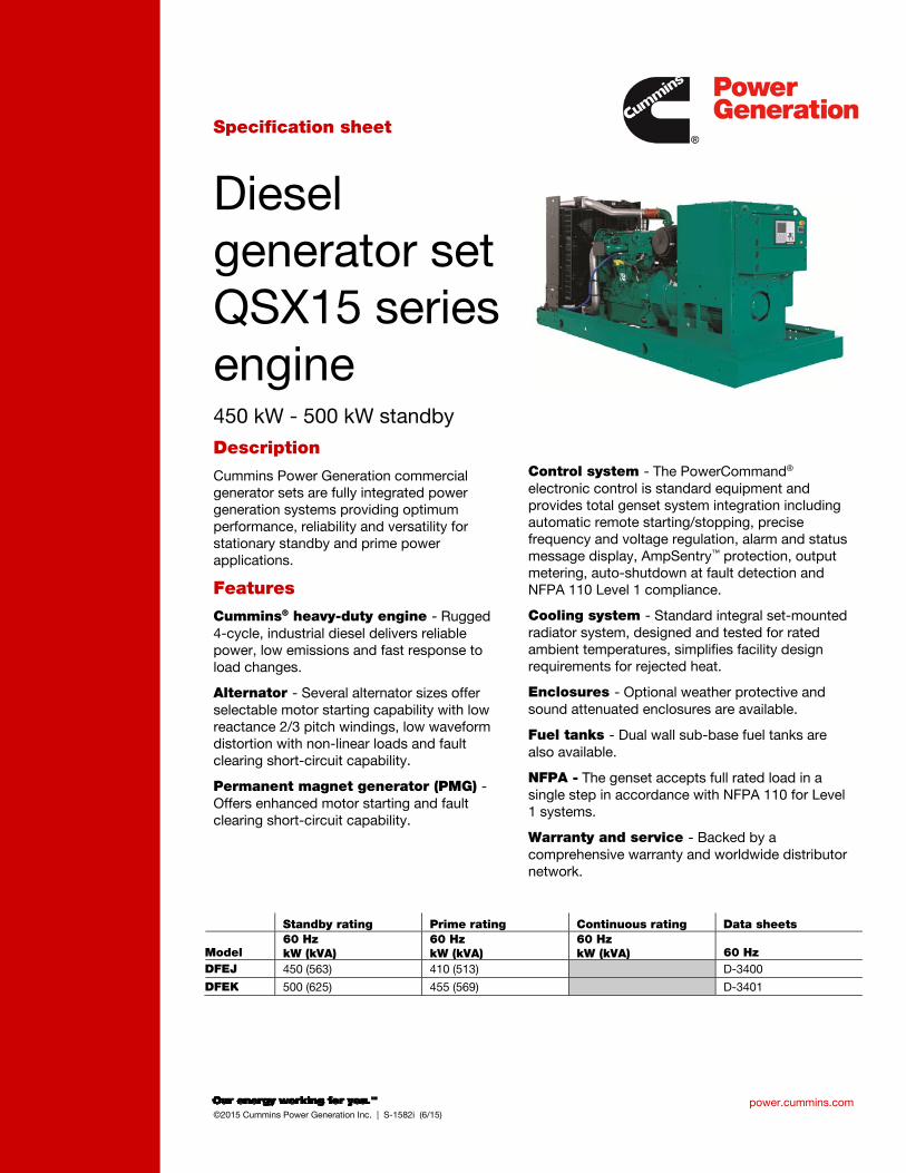
Specification sheet
Diesel generator set QSX15 series engine 450 kW - 500 kW standby
Description
Cummins Power Generation commercial generator sets are fully integrated power generation systems providing optimum performance, reliability and versatility for stationary standby and prime power applications.
Features
Cummins® heavy-duty engine - Rugged 4-cycle, industrial diesel delivers reliable power, low emissions and fast response to load changes.
Alternator - Several alternator sizes offer selectable motor starting capability with low reactance 2/3 pitch windings, low waveform distortion with non-linear loads and fault clearing short-circuit capability.
Permanent magnet generator (PMG) - Offers enhanced motor starting and fault clearing short-circuit capability.
Control system - The PowerCommand® electronic control is standard equipment and provides total genset system integration including automatic remote starting/stopping, precise frequency and voltage regulation, alarm and status message display, AmpSentry™ protection, output metering, auto-shutdown at fault detection and NFPA 110 Level 1 compliance.
Cooling system - Standard integral set-mounted radiator system, designed and tested for rated ambient temperatures, simplifies facility design requirements for rejected heat.
Enclosures - Optional weather protective and sound attenuated enclosures are available.
Fuel tanks - Dual wall sub-base fuel tanks are also available.
NFPA - The genset accepts full rated load in a single step in accordance with NFPA 110 for Level 1 systems.
Warranty and service - Backed by a comprehensive warranty and worldwide distributor network.
Standby rating Prime rating Continuous rating Data sheets
Model 60 Hz kW (kVA)
60 Hz kW (kVA)
60 Hz kW (kVA) 60 Hz
DFEJ 450 (563) 410 (513) D-3400
DFEK 500 (625) 455 (569) D-3401
fc002
Rectangle
power.cummins.com ©2015 Cummins Power Generation Inc. | S-1582i (6/15)
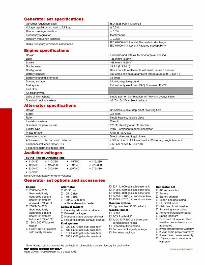
Generator set specifications Governor regulation class ISO 8528 Part 1 Class G3
Voltage regulation, no load to full load ± 0.5%
Random voltage variation ± 0.5%
Frequency regulation Isochronous
Random frequency variation ± 0.25%
Radio frequency emissions compliance IEC 61000-4-2: Level 4 Electrostatic discharge IEC 61000-4-3: Level 3 Radiated susceptibility
Engine specifications Design Turbocharged with air-to-air charge air cooling
Bore 136.9 mm (5.39 in)
Stroke 168.9 mm (6.65 in)
Displacement 14.9 L (912.0 in3)
Configuration Cast iron with replaceable wet liners, in-line 6 cylinder
Battery capacity 900 amps minimum at ambient temperature of 0 °C (32 °F)
Battery charging alternator 35 amps
Starting voltage 24 volt, negative ground
Fuel system Full authority electronic (FAE) Cummins HPI-TP
Fuel filter
Air cleaner type
Lube oil filter type(s) Single spin-on combination full flow and bypass filters
Standard cooling system 40 °C (104 °F) ambient radiator
Alternator specifications Design Brushless, 4 pole, drip proof revolving field
Stator 2/3 pitch
Rotor Single bearing, flexible discs
Insulation system Class H
Standard temperature rise 125 ºC standby at 40 °C ambient
Exciter type PMG (Permanent magnet generator)
Phase rotation A (U), B (V), C (W)
Alternator cooling Direct drive centrifugal blower
AC waveform total harmonic distortion < 5% no load to full linear load, < 3% for any single harmonic
Telephone influence factor (TIF) < 50 per NEMA MG1-22.43
Telephone harmonic factor (THF) < 3
Available voltages 60 Hz line–neutral/line-line
110/190
120/208
230/400
347/600
110/220
127/220
240/416
115/200
139/240
255/440
115/230
220/380
277/480
Note: Consult factory for other voltages.
Generator set options and accessories
Engine 208/240/480 V
thermostatically controlled coolant heater for ambient above 4.5 C (40 F)
208/240/480 V thermostatically controlled coolant heater for ambient below 4.5 C (40 F)
120 V 300 W lube oil heater
Heavy duty air cleaner with safety element
Alternator 80 C rise 105 C rise 150 C rise 120/240 V 300 W
anti-condensation heater
Exhaust System Critical grade exhaust silencer Exhaust packages Industrial grade exhaust silencer Residential grade exhaust silencer
Fuel system 1022 L (270 gal) sub-base tank 1136 L (300 gal) sub-base tank 1514 L (400 gal) sub-base tank 1893 L (500 gal) sub-base tank
2271 L (600 gal) sub-base tank 2498 L (660 gal) sub-base tank 3218 L (850 gal) sub-base tank 6435 L (1700 gal) sub-base tank 9558 L (2525 gal) sub-base tank
Cooling system High ambient 50 °C radiator
Control panel PC3.3 PC3.3 with MLD 120/240 V 100 W control anti-
condensation heater Ground fault indication Remote fault signal package Run relay package
Generator set AC entrance box Battery Battery charger Export box packaging UL 2200 Listed Main line circuit breaker Paralleling accessories Remote annunciator panel Spring isolators Enclosure: aluminum, steel,
weather protective or sound attenuated
2 year standby power warranty 2 year prime power warranty 5 year basic power warranty 10 year major components
warranty
Note: Some options may not be available on all models - consult factory for availability.
power.cummins.com ©2015 Cummins Power Generation Inc. | S-1582i (6/15)
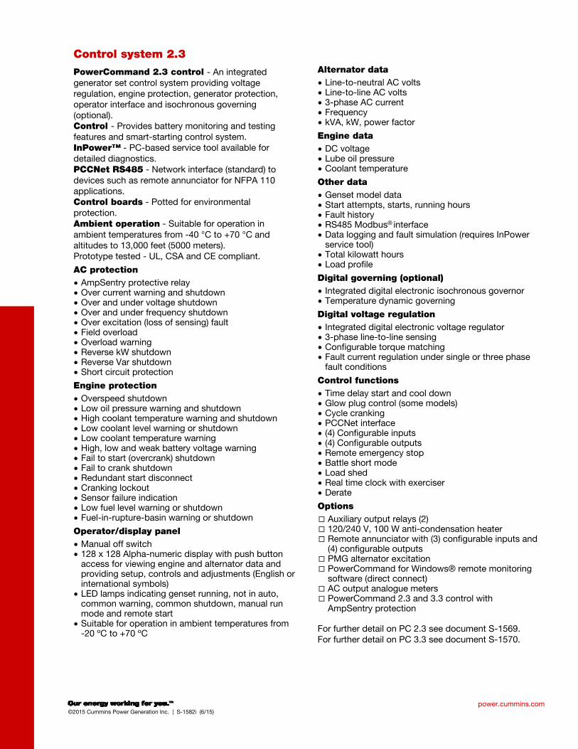
Control system 2.3
PowerCommand 2.3 control - An integrated generator set control system providing voltage regulation, engine protection, generator protection, operator interface and isochronous governing (optional). Control - Provides battery monitoring and testing features and smart-starting control system. InPower™ - PC-based service tool available for detailed diagnostics. PCCNet RS485 - Network interface (standard) to devices such as remote annunciator for NFPA 110 applications. Control boards - Potted for environmental protection. Ambient operation - Suitable for operation in ambient temperatures from -40 °C to +70 °C and altitudes to 13,000 feet (5000 meters). Prototype tested - UL, CSA and CE compliant.
AC protection
AmpSentry protective relay Over current warning and shutdown Over and under voltage shutdown Over and under frequency shutdown Over excitation (loss of sensing) fault Field overload Overload warning Reverse kW shutdown Reverse Var shutdown Short circuit protection
Engine protection
Overspeed shutdown Low oil pressure warning and shutdown High coolant temperature warning and shutdown Low coolant level warning or shutdown Low coolant temperature warning High, low and weak battery voltage warning Fail to start (overcrank) shutdown Fail to crank shutdown Redundant start disconnect Cranking lockout Sensor failure indication Low fuel level warning or shutdown Fuel-in-rupture-basin warning or shutdown
Operator/display panel
Manual off switch 128 x 128 Alpha-numeric display with push button
access for viewing engine and alternator data and providing setup, controls and adjustments (English or international symbols)
LED lamps indicating genset running, not in auto, common warning, common shutdown, manual run mode and remote start
Suitable for operation in ambient temperatures from -20 ºC to +70 ºC
Alternator data
Line-to-neutral AC volts Line-to-line AC volts 3-phase AC current Frequency kVA, kW, power factor
Engine data
DC voltage Lube oil pressure Coolant temperature
Other data
Genset model data Start attempts, starts, running hours Fault history RS485 Modbus®
interface Data logging and fault simulation (requires InPower
service tool) Total kilowatt hours Load profile
Digital governing (optional)
Integrated digital electronic isochronous governor Temperature dynamic governing
Digital voltage regulation
Integrated digital electronic voltage regulator 3-phase line-to-line sensing Configurable torque matching Fault current regulation under single or three phase
fault conditions
Control functions
Time delay start and cool down Glow plug control (some models) Cycle cranking PCCNet interface (4) Configurable inputs (4) Configurable outputs Remote emergency stop Battle short mode Load shed Real time clock with exerciser Derate
Options
Auxiliary output relays (2) 120/240 V, 100 W anti-condensation heater Remote annunciator with (3) configurable inputs and
(4) configurable outputs PMG alternator excitation PowerCommand for Windows® remote monitoring
software (direct connect) AC output analogue meters PowerCommand 2.3 and 3.3 control with
AmpSentry protection
For further detail on PC 2.3 see document S-1569. For further detail on PC 3.3 see document S-1570.
North America
1400 73rd Avenue N.E.
Minneapolis, MN 55432
USA
Phone 763 574 5000
Fax 763 574 5298
©2015 Cummins Power Generation Inc. All rights reserved.
Cummins Power Generation and Cummins are registered trademarks of Cummins Inc. PowerCommand, AmpSentry, InPower
and “Our energy working for you.” are trademarks of Cummins Power Generation. Other company, product, or service names
may be trademarks or service marks of others. Specifications are subject to change without notice.
S-1582i (6/15)
power.cummins.com
Emergency standby power (ESP): Applicable for supplying power to varying electrical load for the duration of power interruption of a reliable utility source. Emergency Standby Power (ESP) is in accordance with ISO 8528. Fuel Stop power in accordance with ISO 3046, AS 2789, DIN 6271 and BS 5514.
Limited-time running power (LTP): Applicable for supplying power to a constant electrical load for limited hours. Limited Time Running Power (LTP) is in accordance with ISO 8528
Prime power (PRP): Applicable for supplying power to varying electrical load for unlimited hours. Prime Power (PRP) is in accordance with ISO 8528. Ten percent overload capability is available in accordance with ISO 3046, AS 2789, DIN 6271 and BS 5514.
Base load (continuous) power (COP): Applicable for supplying power continuously to a constant electrical load for unlimited hours. Continuous Power (COP) in accordance with ISO 8528, ISO 3046, AS 2789, DIN 6271 and BS 5514.
This outline drawing is for reference only. See respective model
data sheet for specific model outline drawing number.
Do not use for installation design
Model Dim “A” mm (in.)
Dim “B” mm (in.)
Dim “C” mm (in.)
Set Weight* dry kg (lbs)
Set Weight* wet kg (lbs)
DFEJ 3864 (152.1) 1524 (60.0) 1812 (71.3) 4098 (9035) 4234 (9335)
DFEK 3864 (152.1) 1524 (60.0) 1812 (71.3) 4325 (9535) 4461 (9835)
* Weights represent a set with standard features. See outline drawings for weights of other configurations.
Codes and standards Codes or standards compliance may not be available with all model configurations – consult factory for availability.
This generator set is designed in facilities certified to ISO 9001 and manufactured in facilities certified to ISO 9001 or ISO 9002.
The generator set is available listed to UL 2200, Stationary Engine Generator Assemblies for all 60 Hz low voltage models. The PowerCommand control is Listed to UL 508 - Category NITW7 for U.S. and Canadian usage. Circuit breaker assemblies are UL 489 Listed for 100% continuous operation and also UL 869A Listed Service Equipment.
The Prototype Test Support (PTS) program verifies the performance integrity of the generator set design. Cummins Power Generation products bearing the PTS symbol meet the prototype test requirements of NFPA 110 for Level 1 systems.
U.S. EPA
Engine certified to Stationary Emergency U.S. EPA New Source Performance Standards, 40 CFR 60 subpart IIII Tier 2 exhaust emission levels. U.S. applications must be applied per this EPA regulation.
All low voltage models are CSA certified to product class 4215-01.
International Building Code
The generator set package is available certified for seismic application in accordance with the following International Building Code: IBC2000, IBC2003, IBC2006, IBC2009 and IBC2012.
Warning: Back feed to a utility system can cause electrocution and/or property damage. Do not connect to any building’s electrical system
except through an approved device or after building main switch is open.
fc002
Rectangle
power.cummins.com ©2015 Cummins Power Generation Inc. | D-3401d (6/15)
Generator set data sheet
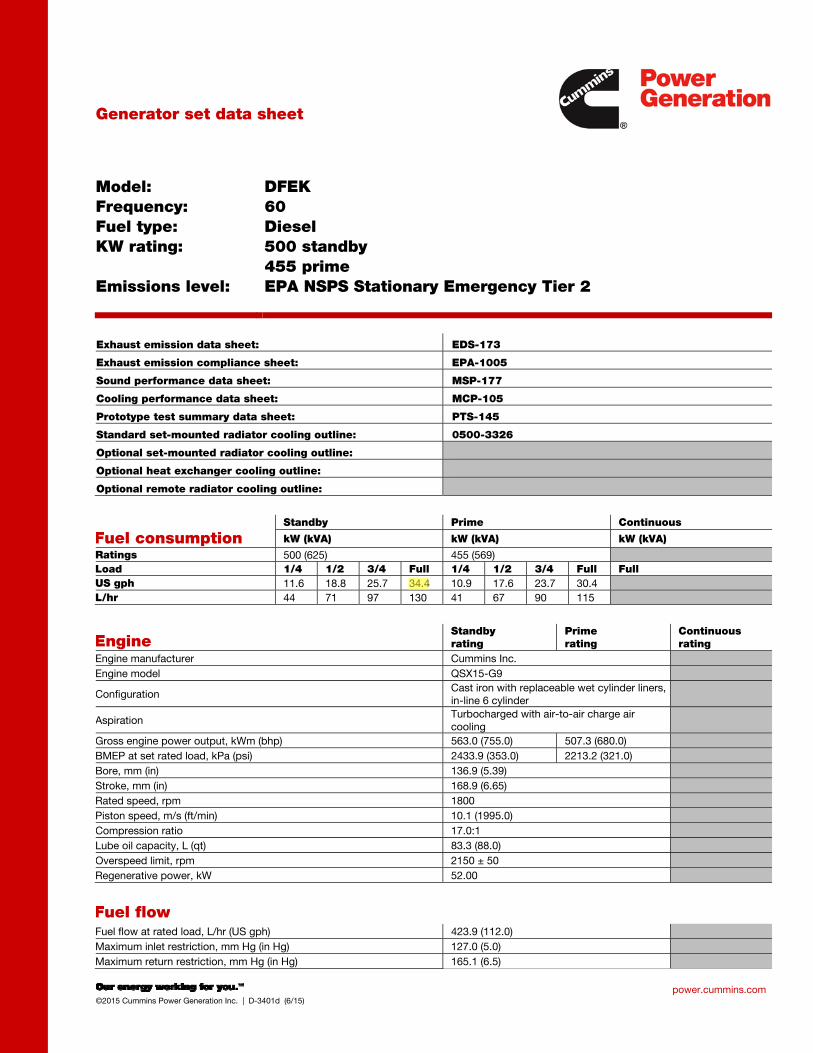
Model: Frequency: Fuel type: KW rating: Emissions level:
DFEK 60 Diesel 500 standby 455 prime EPA NSPS Stationary Emergency Tier 2
Exhaust emission data sheet: EDS-173
Exhaust emission compliance sheet: EPA-1005
Sound performance data sheet: MSP-177
Cooling performance data sheet: MCP-105
Prototype test summary data sheet: PTS-145
Standard set-mounted radiator cooling outline: 0500-3326
Optional set-mounted radiator cooling outline:
Optional heat exchanger cooling outline:
Optional remote radiator cooling outline:
Fuel consumption Standby Prime Continuous
kW (kVA) kW (kVA) kW (kVA)
Ratings 500 (625) 455 (569)
Load 1/4 1/2 3/4 Full 1/4 1/2 3/4 Full Full
US gph 11.6 18.8 25.7 34.4 10.9 17.6 23.7 30.4
L/hr 44 71 97 130 41 67 90 115
Engine Standby rating
Prime rating
Continuous rating
Engine manufacturer Cummins Inc.
Engine model QSX15-G9
Configuration Cast iron with replaceable wet cylinder liners, in-line 6 cylinder
Aspiration Turbocharged with air-to-air charge air cooling
Gross engine power output, kWm (bhp) 563.0 (755.0) 507.3 (680.0)
BMEP at set rated load, kPa (psi) 2433.9 (353.0) 2213.2 (321.0)
Bore, mm (in) 136.9 (5.39)
Stroke, mm (in) 168.9 (6.65)
Rated speed, rpm 1800
Piston speed, m/s (ft/min) 10.1 (1995.0)
Compression ratio 17.0:1
Lube oil capacity, L (qt) 83.3 (88.0)
Overspeed limit, rpm 2150 ± 50
Regenerative power, kW 52.00
Fuel flow Fuel flow at rated load, L/hr (US gph) 423.9 (112.0)
Maximum inlet restriction, mm Hg (in Hg) 127.0 (5.0)
Maximum return restriction, mm Hg (in Hg) 165.1 (6.5)
fc002
Rectangle
fc002
Highlight
fc002
Line
power.cummins.com ©2015 Cummins Power Generation Inc. | D-3401d (6/15)
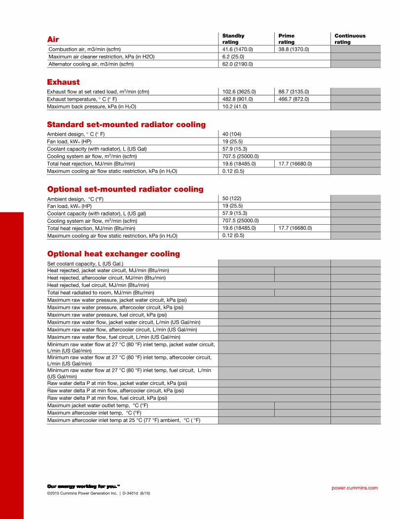
Air Standby rating
Prime rating
Continuous rating
Combustion air, m3/min (scfm) 41.6 (1470.0) 38.8 (1370.0)
Maximum air cleaner restriction, kPa (in H2O) 6.2 (25.0)
Alternator cooling air, m3/min (scfm) 62.0 (2190.0)
Exhaust
Exhaust flow at set rated load, m3/min (cfm) 102.6 (3625.0) 88.7 (3135.0)
Exhaust temperature, C ( F) 482.8 (901.0) 466.7 (872.0)
Maximum back pressure, kPa (in H2O) 10.2 (41.0)
Standard set-mounted radiator cooling
Ambient design, C ( F) 40 (104)
Fan load, kWm (HP) 19 (25.5)
Coolant capacity (with radiator), L (US Gal) 57.9 (15.3)
Cooling system air flow, m3/min (scfm) 707.5 (25000.0)
Total heat rejection, MJ/min (Btu/min) 19.6 (18485.0) 17.7 (16680.0)
Maximum cooling air flow static restriction, kPa (in H2O) 0.12 (0.5)
Optional set-mounted radiator cooling
Ambient design, °C (°F) 50 (122)
Fan load, kWm (HP) 19 (25.5)
Coolant capacity (with radiator), L (US gal) 57.9 (15.3)
Cooling system air flow, m3/min (scfm) 707.5 (25000.0)
Total heat rejection, MJ/min (Btu/min) 19.6 (18485.0) 17.7 (16680.0)
Maximum cooling air flow static restriction, kPa (in H2O) 0.12 (0.5)
Optional heat exchanger cooling
Set coolant capacity, L (US Gal.)
Heat rejected, jacket water circuit, MJ/min (Btu/min)
Heat rejected, aftercooler circuit, MJ/min (Btu/min)
Heat rejected, fuel circuit, MJ/min (Btu/min)
Total heat radiated to room, MJ/min (Btu/min)
Maximum raw water pressure, jacket water circuit, kPa (psi)
Maximum raw water pressure, aftercooler circuit, kPa (psi)
Maximum raw water pressure, fuel circuit, kPa (psi)
Maximum raw water flow, jacket water circuit, L/min (US Gal/min)
Maximum raw water flow, aftercooler circuit, L/min (US Gal/min)
Maximum raw water flow, fuel circuit, L/min (US Gal/min)
Minimum raw water flow at 27 °C (80 °F) inlet temp, jacket water circuit, L/min (US Gal/min)
Minimum raw water flow at 27 °C (80 °F) inlet temp, aftercooler circuit, L/min (US Gal/min)
Minimum raw water flow at 27 °C (80 °F) inlet temp, fuel circuit, L/min (US Gal/min)
Raw water delta P at min flow, jacket water circuit, kPa (psi)
Raw water delta P at min flow, aftercooler circuit, kPa (psi)
Raw water delta P at min flow, fuel circuit, kPa (psi)
Maximum jacket water outlet temp, °C (°F)
Maximum aftercooler inlet temp, °C (°F)
Maximum aftercooler inlet temp at 25 °C (77 °F) ambient, °C ( °F)
power.cummins.com ©2015 Cummins Power Generation Inc. | D-3401d (6/15)
Optional remote radiator cooling1 Standby rating
Prime rating
Continuous rating
Set coolant capacity, L (US gal)
Max flow rate at max friction head, jacket water circuit, L/min (US gal/min)
Max flow rate at max friction head, aftercooler circuit, L/min (US gal/min)
Heat rejected, jacket water circuit, MJ/min (Btu/min)
Heat rejected, aftercooler circuit, MJ/min (Btu/min)
Heat rejected, fuel circuit, MJ/min (Btu/min)
Total heat radiated to room, MJ/min (Btu/min)
Maximum friction head, jacket water circuit, kPa (psi)
Maximum friction head, aftercooler circuit, kPa (psi)
Maximum static head, jacket water circuit, m (ft)
Maximum static head, aftercooler circuit, m (ft)
Maximum jacket water outlet temp, C (F)
Maximum aftercooler inlet temp at 25 C (77 F) ambient, C (F)
Maximum aftercooler inlet temp, C (F)
Maximum fuel flow, L/hr (US gph)
Maximum fuel return line restriction, kPa (in Hg)
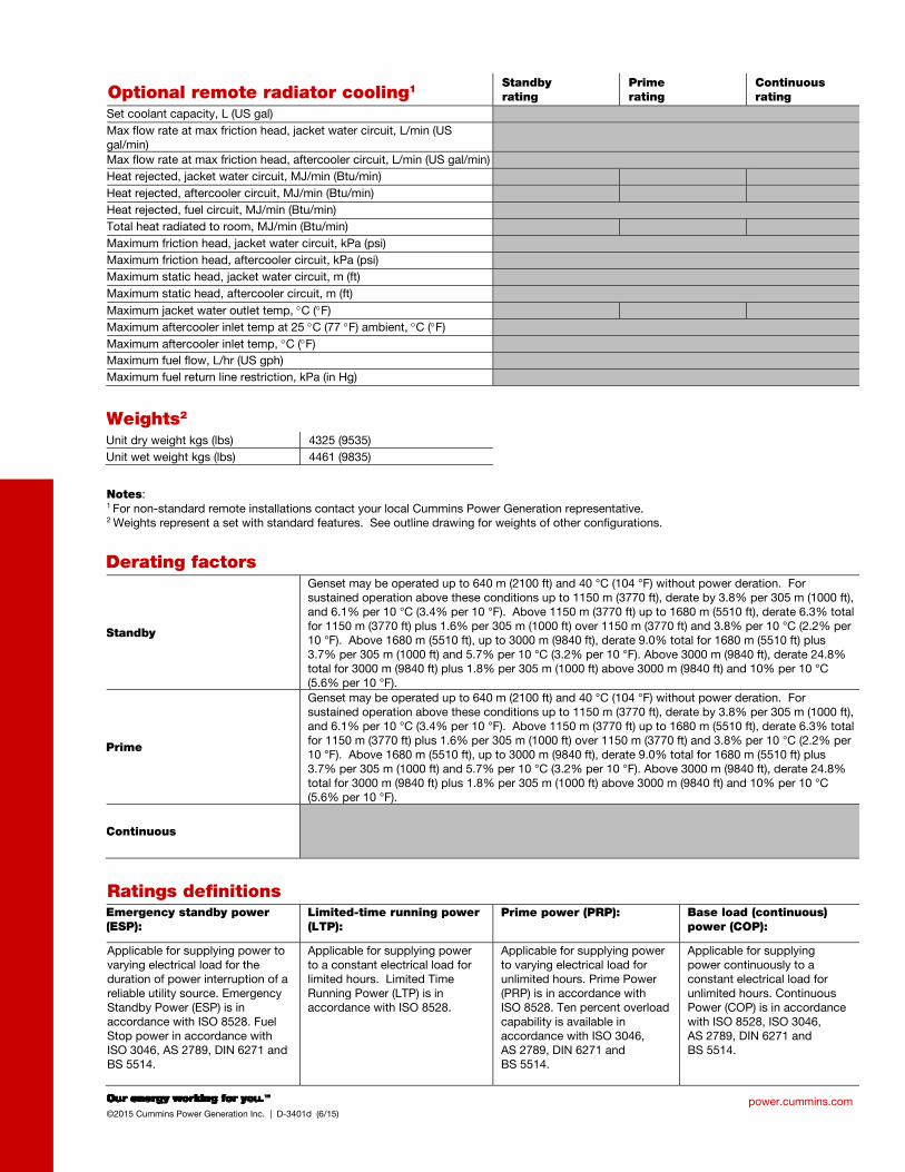
Weights2
Unit dry weight kgs (lbs) 4325 (9535)
Unit wet weight kgs (lbs) 4461 (9835)
Notes: 1 For non-standard remote installations contact your local Cummins Power Generation representative. 2 Weights represent a set with standard features. See outline drawing for weights of other configurations.
Derating factors
Standby
Genset may be operated up to 640 m (2100 ft) and 40 °C (104 °F) without power deration. For sustained operation above these conditions up to 1150 m (3770 ft), derate by 3.8% per 305 m (1000 ft), and 6.1% per 10 °C (3.4% per 10 °F). Above 1150 m (3770 ft) up to 1680 m (5510 ft), derate 6.3% total for 1150 m (3770 ft) plus 1.6% per 305 m (1000 ft) over 1150 m (3770 ft) and 3.8% per 10 °C (2.2% per 10 °F). Above 1680 m (5510 ft), up to 3000 m (9840 ft), derate 9.0% total for 1680 m (5510 ft) plus 3.7% per 305 m (1000 ft) and 5.7% per 10 °C (3.2% per 10 °F). Above 3000 m (9840 ft), derate 24.8% total for 3000 m (9840 ft) plus 1.8% per 305 m (1000 ft) above 3000 m (9840 ft) and 10% per 10 °C (5.6% per 10 °F).
Prime
Genset may be operated up to 640 m (2100 ft) and 40 °C (104 °F) without power deration. For sustained operation above these conditions up to 1150 m (3770 ft), derate by 3.8% per 305 m (1000 ft), and 6.1% per 10 °C (3.4% per 10 °F). Above 1150 m (3770 ft) up to 1680 m (5510 ft), derate 6.3% total for 1150 m (3770 ft) plus 1.6% per 305 m (1000 ft) over 1150 m (3770 ft) and 3.8% per 10 °C (2.2% per 10 °F). Above 1680 m (5510 ft), up to 3000 m (9840 ft), derate 9.0% total for 1680 m (5510 ft) plus 3.7% per 305 m (1000 ft) and 5.7% per 10 °C (3.2% per 10 °F). Above 3000 m (9840 ft), derate 24.8% total for 3000 m (9840 ft) plus 1.8% per 305 m (1000 ft) above 3000 m (9840 ft) and 10% per 10 °C (5.6% per 10 °F).
Continuous
Ratings definitions
Emergency standby power (ESP):
Limited-time running power (LTP):
Prime power (PRP): Base load (continuous) power (COP):
Applicable for supplying power to varying electrical load for the duration of power interruption of a reliable utility source. Emergency Standby Power (ESP) is in accordance with ISO 8528. Fuel Stop power in accordance with ISO 3046, AS 2789, DIN 6271 and BS 5514.
Applicable for supplying power to a constant electrical load for limited hours. Limited Time Running Power (LTP) is in accordance with ISO 8528.
Applicable for supplying power to varying electrical load for unlimited hours. Prime Power (PRP) is in accordance with ISO 8528. Ten percent overload capability is available in accordance with ISO 3046, AS 2789, DIN 6271 and BS 5514.
Applicable for supplying power continuously to a constant electrical load for unlimited hours. Continuous Power (COP) is in accordance with ISO 8528, ISO 3046, AS 2789, DIN 6271 and BS 5514.
North America
1400 73rd Avenue N.E.
Minneapolis, MN 55432
USA
Phone 763 574 5000
Fax 763 574 5298
©2015 Cummins Power Generation Inc. All rights reserved.
Cummins Power Generation and Cummins are registered trademarks of Cummins Inc. PowerCommand, AmpSentry, InPower
and “Our energy working for you.” are trademarks of Cummins Power Generation. Other company, product, or service names
may be trademarks or service marks of others. Specifications are subject to change without notice.
D-3401d (6/15)
power.cummins.com
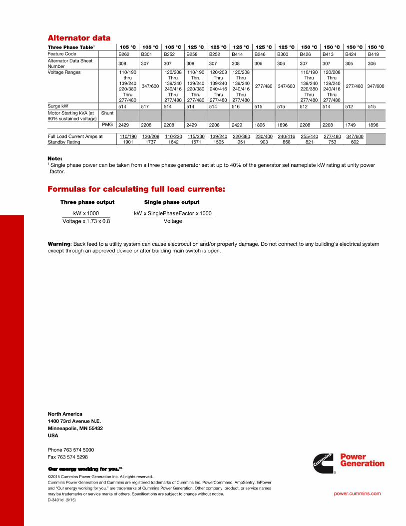
Alternator data Three Phase Table1 105 °C 105 °C 105 °C 125 °C 125 °C 125 °C 125 °C 125 °C 150 °C 150 °C 150 °C 150 °C
Feature Code B262 B301 B252 B258 B252 B414 B246 B300 B426 B413 B424 B419
Alternator Data Sheet Number
308 307 307 308 307 308 306 306 307 307 305 306
Voltage Ranges 110/190 thru
139/240 220/380
Thru 277/480
347/600
120/208 Thru
139/240 240/416
Thru 277/480
110/190 Thru
139/240 220/380
Thru 277/480
120/208 Thru
139/240 240/416
Thru 277/480
120/208 Thru
139/240 240/416
Thru 277/480
277/480 347/600
110/190 Thru
139/240 220/380
Thru 277/480
120/208 Thru
139/240 240/416
Thru 277/480
277/480 347/600
Surge kW 514 517 514 514 514 516 515 515 512 514 512 515
Motor Starting kVA (at 90% sustained voltage)
Shunt
PMG 2429 2208 2208 2429 2208 2429 1896 1896 2208 2208 1749 1896
Full Load Current Amps at Standby Rating
110/190 1901
120/208 1737
110/220 1642
115/230 1571
139/240 1505
220/380 951
230/400 903
240/416 868
255/440 821
277/480 753
347/600 602
Note: 1 Single phase power can be taken from a three phase generator set at up to 40% of the generator set nameplate kW rating at unity power factor.
Formulas for calculating full load currents:
Three phase output Single phase output
Warning: Back feed to a utility system can cause electrocution and/or property damage. Do not connect to any building’s electrical system
except through an approved device or after building main switch is open.
Voltage
1000 x eFactorSinglePhas x kW
0.8 x 1.73 x Voltage
1000 x kW
Our energy working for you.™
www.cumminspower.com 2014 Cummins Power Generation Inc. All rights reserved. Cummins Power Generation and Cummins are registered trademarks of Cummins Inc. PowerCommand and “Our energy working for you.” are trademarks of Cummins Power Generation. Specifications are subject to change without notice. S-1443z (9/14)
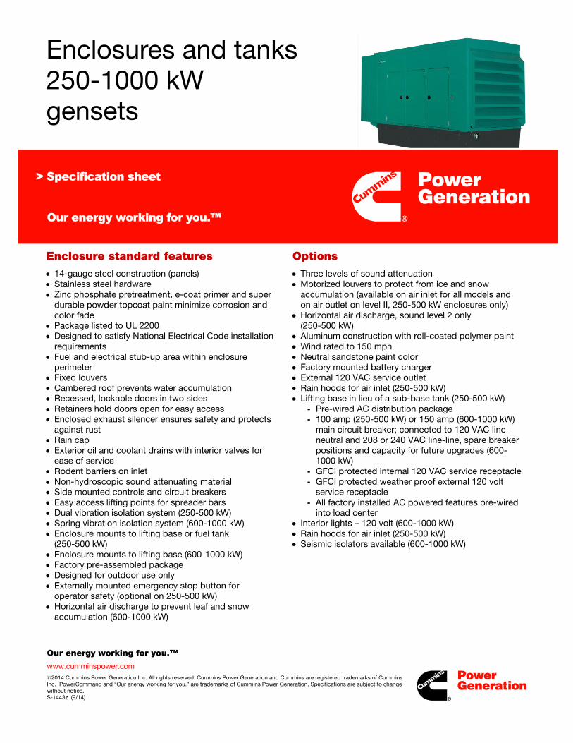
Enclosures and tanks 250-1000 kW gensets
Enclosure standard features • 14-gauge steel construction (panels) • Stainless steel hardware • Zinc phosphate pretreatment, e-coat primer and super
durable powder topcoat paint minimize corrosion and color fade
• Package listed to UL 2200 • Designed to satisfy National Electrical Code installation
requirements • Fuel and electrical stub-up area within enclosure
perimeter • Fixed louvers • Cambered roof prevents water accumulation • Recessed, lockable doors in two sides • Retainers hold doors open for easy access • Enclosed exhaust silencer ensures safety and protects
against rust • Rain cap • Exterior oil and coolant drains with interior valves for
ease of service • Rodent barriers on inlet • Non-hydroscopic sound attenuating material • Side mounted controls and circuit breakers • Easy access lifting points for spreader bars • Dual vibration isolation system (250-500 kW) • Spring vibration isolation system (600-1000 kW) • Enclosure mounts to lifting base or fuel tank
(250-500 kW) • Enclosure mounts to lifting base (600-1000 kW) • Factory pre-assembled package • Designed for outdoor use only • Externally mounted emergency stop button for
operator safety (optional on 250-500 kW) • Horizontal air discharge to prevent leaf and snow
accumulation (600-1000 kW)
Options • Three levels of sound attenuation • Motorized louvers to protect from ice and snow
accumulation (available on air inlet for all models and on air outlet on level II, 250-500 kW enclosures only)
• Horizontal air discharge, sound level 2 only (250-500 kW)
• Aluminum construction with roll-coated polymer paint • Wind rated to 150 mph • Neutral sandstone paint color • Factory mounted battery charger • External 120 VAC service outlet • Rain hoods for air inlet (250-500 kW) • Lifting base in lieu of a sub-base tank (250-500 kW)
- Pre-wired AC distribution package - 100 amp (250-500 kW) or 150 amp (600-1000 kW)
main circuit breaker; connected to 120 VAC line-neutral and 208 or 240 VAC line-line, spare breaker positions and capacity for future upgrades (600-1000 kW)
- GFCI protected internal 120 VAC service receptacle - GFCI protected weather proof external 120 volt
service receptacle - All factory installed AC powered features pre-wired
into load center • Interior lights – 120 volt (600-1000 kW) • Rain hoods for air inlet (250-500 kW) • Seismic isolators available (600-1000 kW)

Our energy working for you.™
www.cumminspower.com 2014 Cummins Power Generation Inc. All rights reserved. Cummins Power Generation and Cummins are registered trademarks of Cummins Inc. PowerCommand and “Our energy working for you.” are trademarks of Cummins Power Generation. Specifications are subject to change without notice. S-1443z (9/14)
Fuel tanks Standard sub-base tank features
• UL 142 Listed • ULC-S601-07 Listed • NFPA37 compliant • Dual walled, steel construction • Emergency tank and rupture basin vents • Tank mounted mechanical fuel gauge • Fuel supply and return tubes • Top mounted leak detection float switch • Low and high level fuel switches • Mounting brackets for optional pump and control
(250-500 kW) • Integral lifting points
Sub-base tank options
• Pre-wired fuel pump and control • Fuel overfill alarm – internal or external • Overflow and tank fill plugs • Five gallon spill fill box – internal or external • Fill pipe extender • Local code approvals available
200-500 kW dual wall sub-base fuel tanks – usable operating hours Genset model (60 Hz)
Gallons/hour at full load
270 gallon tank
300 gallon tank
400 gallon tank
500 gallon tank
600 gallon tank
660 gallon tank
720 gallon tank
850 gallon tank
1420 gallon tank
1470 gallon tank
1700 gallon tank
2050 gallon tank
2525 gallon tank
250 DQDAA 20 14 15 20 25 30 33 36 72 74 104 275 DQDAB 21 13 14 19 24 29 31 34 66 70 96 300 DQDAC 23 12 13 17 22 26 29 31 61 64 88 300 DQHAB 23 12 13 17 22 26 29 37 74 450 DFEJ 30 9 10 13 17 20 22 28 57 84 500 DFEK 34 8 9 11 15 18 19 25 50 74
Operating hours are measured at 60 Hz, standby rating.
600-1000 kW dual wall sub-base fuel tanks – usable operating hours
Genset model
Gallons/hour at full load
200 gallon tank
660 gallon tank
1000 gallon tank
1500 gallon tank
2000 gallon tank
2400 gallon tank
600 DQCA 42 5 16 24 36 48 57 600 DQPAA 45 4 15 22 33 44 53 650 DQPAB 50 4 13 20 30 40 48 750 DQCB 51 4 13 20 29 39 47 750 DQFAA 53 4 12 19 28 38 45 800 DQCC 53 4 12 19 28 38 45 800 DQFAB 56 4 12 18 27 36 43 900 DQFAC 64 3 10 16 23 31 38 1000 DQFAD 72 3 9 14 21 28 33
*3000 gallon tank offered as an accessory kit – refer to NAAC-5853 spec sheet
- Operating hours are measured at 60Hz, standby rating. - Up to 90% fill alarm to comply with NFPA30, operating capacity is reduced by 10%.
fc002
Rectangle
fc002
Line
.
Our energy working for you.™
www.cumminspower.com 2014 Cummins Power Generation Inc. All rights reserved. Cummins Power Generation and Cummins are registered trademarks of Cummins Inc. PowerCommand and “Our energy working for you.” are trademarks of Cummins Power Generation. Specifications are subject to change without notice. S-1443z (9/14)
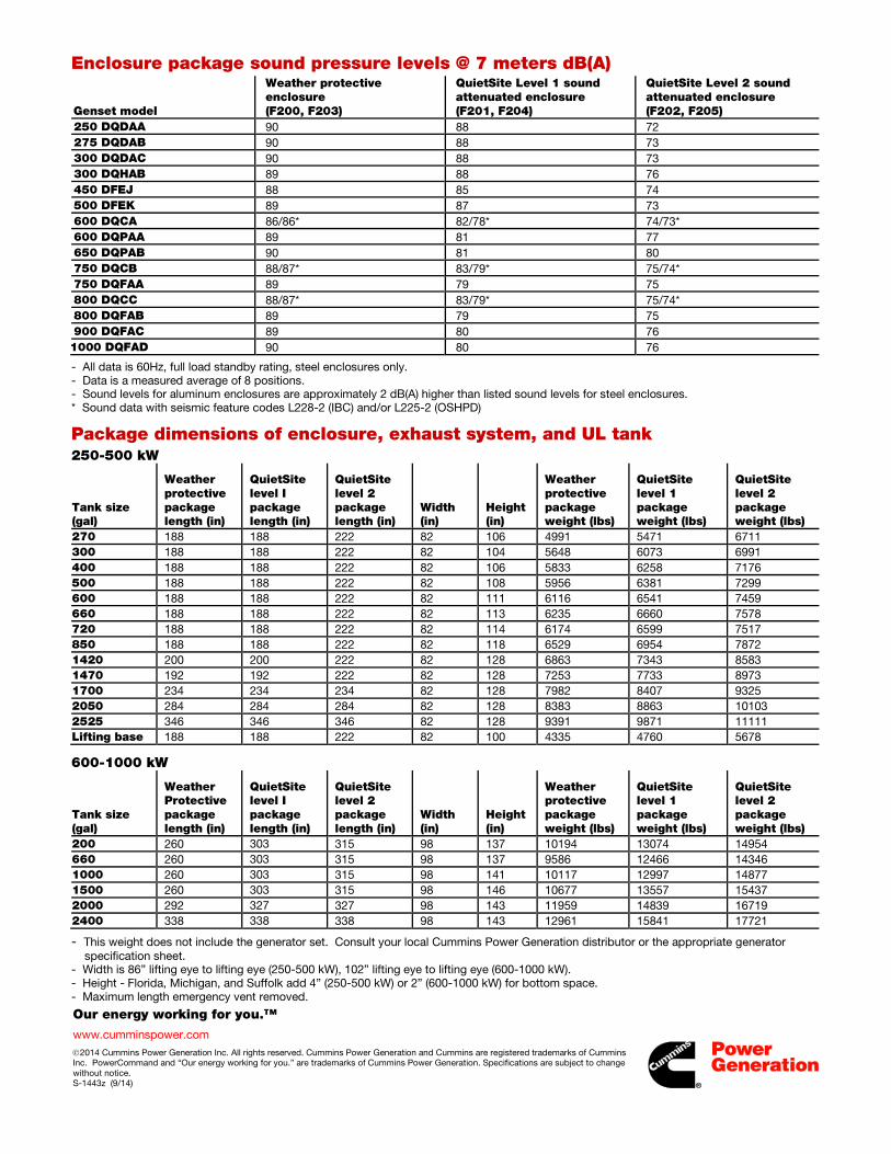
Enclosure package sound pressure levels @ 7 meters dB(A)
Genset model
Weather protective enclosure (F200, F203)
QuietSite Level 1 sound attenuated enclosure (F201, F204)
QuietSite Level 2 sound attenuated enclosure (F202, F205)
250 DQDAA 90 88 72 275 DQDAB 90 88 73 300 DQDAC 90 88 73 300 DQHAB 89 88 76 450 DFEJ 88 85 74 500 DFEK 89 87 73 600 DQCA 86/86* 82/78* 74/73* 600 DQPAA 89 81 77 650 DQPAB 90 81 80 750 DQCB 88/87* 83/79* 75/74* 750 DQFAA 89 79 75 800 DQCC 88/87* 83/79* 75/74* 800 DQFAB 89 79 75 900 DQFAC 89 80 76 1000 DQFAD 90 80 76
- All data is 60Hz, full load standby rating, steel enclosures only. - Data is a measured average of 8 positions. - Sound levels for aluminum enclosures are approximately 2 dB(A) higher than listed sound levels for steel enclosures. * Sound data with seismic feature codes L228-2 (IBC) and/or L225-2 (OSHPD)
Package dimensions of enclosure, exhaust system, and UL tank 250-500 kW
Tank size (gal)
Weather protective package length (in)
QuietSite level I package length (in)
QuietSite level 2 package length (in)
Width (in)
Height (in)
Weather protective package weight (lbs)
QuietSite level 1 package weight (lbs)
QuietSite level 2 package weight (lbs)
270 188 188 222 82 106 4991 5471 6711 300 188 188 222 82 104 5648 6073 6991 400 188 188 222 82 106 5833 6258 7176 500 188 188 222 82 108 5956 6381 7299 600 188 188 222 82 111 6116 6541 7459 660 188 188 222 82 113 6235 6660 7578 720 188 188 222 82 114 6174 6599 7517 850 188 188 222 82 118 6529 6954 7872 1420 200 200 222 82 128 6863 7343 8583 1470 192 192 222 82 128 7253 7733 8973 1700 234 234 234 82 128 7982 8407 9325 2050 284 284 284 82 128 8383 8863 10103 2525 346 346 346 82 128 9391 9871 11111 Lifting base 188 188 222 82 100 4335 4760 5678
600-1000 kW
Tank size (gal)
Weather Protective package length (in)
QuietSite level I package length (in)
QuietSite level 2 package length (in)
Width (in)
Height (in)
Weather protective package weight (lbs)
QuietSite level 1 package weight (lbs)
QuietSite level 2 package weight (lbs)
200 260 303 315 98 137 10194 13074 14954 660 260 303 315 98 137 9586 12466 14346 1000 260 303 315 98 141 10117 12997 14877 1500 260 303 315 98 146 10677 13557 15437 2000 292 327 327 98 143 11959 14839 16719 2400 338 338 338 98 143 12961 15841 17721
- This weight does not include the generator set. Consult your local Cummins Power Generation distributor or the appropriate generator specification sheet.
- Width is 86” lifting eye to lifting eye (250-500 kW), 102” lifting eye to lifting eye (600-1000 kW). - Height - Florida, Michigan, and Suffolk add 4” (250-500 kW) or 2” (600-1000 kW) for bottom space. - Maximum length emergency vent removed.
fc002
Rectangle
fc002
Line
fc002
Rectangle

.
Our energy working for you.™
www.cumminspower.com 2014 Cummins Power Generation Inc. All rights reserved. Cummins Power Generation and Cummins are registered trademarks of Cummins Inc. PowerCommand and “Our energy working for you.” are trademarks of Cummins Power Generation. Specifications are subject to change without notice. S-1443z (9/14)
CSA - The generator set is CSA certified to product class 4215-01.
UL - The generator set is available Listed to UL 2200, Stationary Engine Generator Assemblies. The PowerCommand control is Listed to UL 508 - Category NITW7 for U.S. and Canadian usage.
See your distributor for more information Americas 1400 73rd Avenue N.E. Minneapolis, MN 55432 USA Phone: 763 574-5000 Fax: 763 574-5298
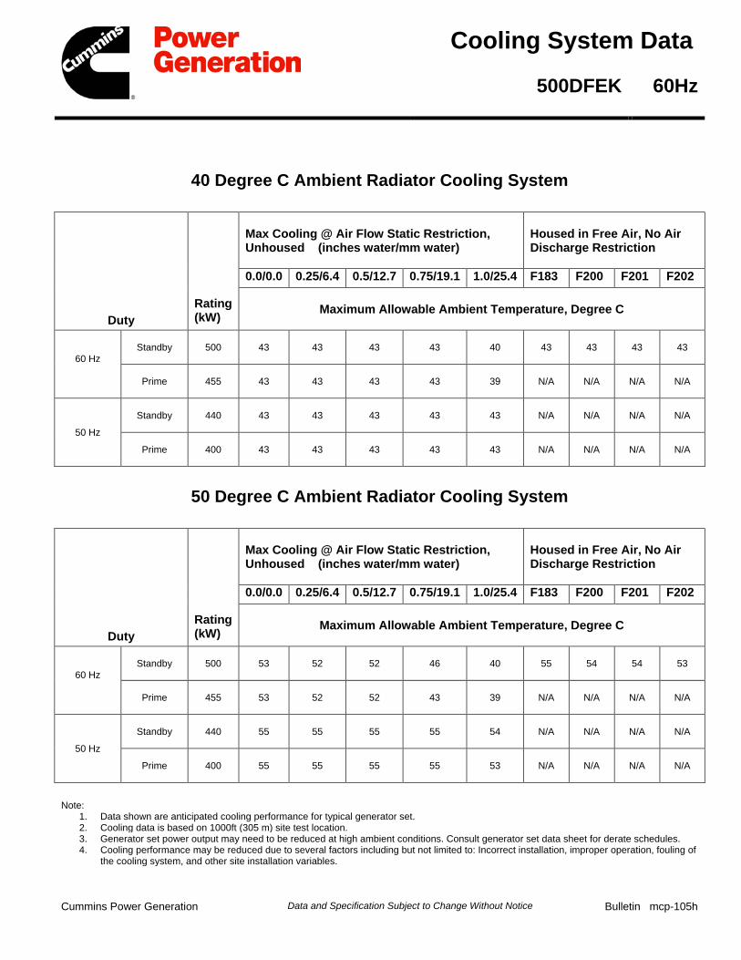
Cooling System Data
500DFEK 60Hz
40 Degree C Ambient Radiator Cooling System
Duty Rating (kW)
Max Cooling @ Air Flow Static Restriction, Unhoused (inches water/mm water)
Housed in Free Air, No Air Discharge Restriction
0.0/0.0 0.25/6.4 0.5/12.7 0.75/19.1 1.0/25.4 F183 F200 F201 F202
Maximum Allowable Ambient Temperature, Degree C
60 Hz Standby 500 43 43 43 43 40 43 43 43 43
Prime 455 43 43 43 43 39 N/A N/A N/A N/A
50 Hz
Standby 440 43 43 43 43 43 N/A N/A N/A N/A
Prime 400 43 43 43 43 43 N/A N/A N/A N/A
50 Degree C Ambient Radiator Cooling System
Duty Rating (kW)
Max Cooling @ Air Flow Static Restriction, Unhoused (inches water/mm water)
Housed in Free Air, No Air Discharge Restriction
0.0/0.0 0.25/6.4 0.5/12.7 0.75/19.1 1.0/25.4 F183 F200 F201 F202
Maximum Allowable Ambient Temperature, Degree C
60 Hz Standby 500 53 52 52 46 40 55 54 54 53
Prime 455 53 52 52 43 39 N/A N/A N/A N/A
50 Hz
Standby 440 55 55 55 55 54 N/A N/A N/A N/A
Prime 400 55 55 55 55 53 N/A N/A N/A N/A
Note: 1. Data shown are anticipated cooling performance for typical generator set.2. Cooling data is based on 1000ft (305 m) site test location.3. Generator set power output may need to be reduced at high ambient conditions. Consult generator set data sheet for derate schedules.4. Cooling performance may be reduced due to several factors including but not limited to: Incorrect installation, improper operation, fouling of
the cooling system, and other site installation variables.
Cummins Power Generation Data and Specification Subject to Change Without Notice Bulletin mcp-105h
fc002
Rectangle
fc002
Line
fc002
Rectangle
fc002
Line
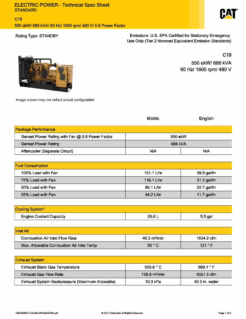
ELECTRIC POWER - Technical Spec Sheet STANDARD
C18
550 ekW/ 688 kVA/ 60Hz/1800 rpm/ 480 V/ 0.8 Power Factor
Rating Type: STANDBY
Image shown may not reflect actual configuration
Package Performance
Genset Power Rating with Fan@ 0.8 Power Factor
Genset Power Rating
Aftercooler (Separate Circuit)
Fuel Consumption
100% Load with Fan
75% Load with Fan
50% Load with Fan
25% Load with Fan
Cooling System1
Engine Coolant Capacity I
Inlet Air
Combustion Air Inlet Flow Rate
Max. Allowable Combustion Air Inlet Temp
Exhaust System
Exhaust Stack Gas Temperature
Exhaust Gas Flow Rate
Exhaust System Backpressure (Maximum Allowable)
Emissions: U.S. EPA Certified for Stationary Emergency Use Only (Tier 2 Nonroad Equivalent Emission Standards)
Metric
N/A
151.1Uhr
118.1 Uhr
86.1 Uhr
44.2 Uhr
20.8 L
46.3 m3/min
50 ° c
520.6 ° c 128.9 m3/min
10.0 kPa
C18
550 ekW/ 688 kVA 60 Hz/ 1800 rpm/ 480 V
English
550 ekW
688 kVA
I N/A
39.9 gal/hr
31.2 gal/hr
22.7 gal/hr
11.7 gal/hr
I 5.5gal
1634.9 cfm
121 ° F
969.1 ° F
4551.5 cfm
40.0 in. water
TSS-DM8517-04-GS-EPG-9045706.pdf © 2017 Caterpillar All Rights Reserved Page 1 of3
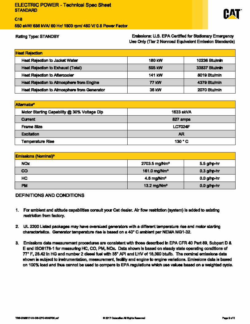
ELECTRIC POWER - Technlcal Spec Sheet STANDARD
C18 550 ekW/ 688 WA/ 80 HZ'/ 1800 ml -480 V/ 0.8 Power FIClor
Rllllng TW&! STANDBY
Haat RaJadlan Haat Rlljedl1111 ID Jackal: watar Haat Rlljedl1111 to Exhauat (Talal)
Haat Rlljedl1111 ID Aftercoalflr
Haat Rlljedl1111 to Mnasplw9 Imm Engine
Haat Rlljedl1111 ID Mnasplw9 Imm Generator
AllBrnata-
Matar starang capability @ 30% Voltage Dip
Clnent
Fl'amll 8lz8
Exl:bllon
Temperature Rl89
Emlllllana (Namlnal)"
NOx
co HC
PM
DEFINITIONS AND CONDITIONS
Emlnlonl: U.S. EPA Certified far Siallon8ly Emarganc:y U119 Only (Tier 2 Nonroad Equivalent Emlnon Slandalde)
180kW 10236 Blum*'
!i95kW 33837 Blum*'
141 kW 8019 Btu/min
T1WI 4379 Btu/min
36WI 2D70 Btu/min
1633akVA
827ampa
LC7024F
AR
130"C
2703.5 mglNm" 5.5~r
181.0 mg/Nm' 0.3~r
4.tlmg/Nm' D.D~r
13.2 mg/Nm" D.D~r
1. Fer amblan1 and altitude capabilities consult ycu Ca1 dealer. AJr llow raabl:tlon (ayOlm) la added to axla!lng nietrldlon hm faclory.
2. UL 2200 Lieted P•cka9M may have CMltSWld genet8lotl writh 8 different Ullnpetelure riff and moCct sl8tli'l9 charact811aa.ca. GenerlltMtampeteture rlae I& baaed on a 40" c amlllen1 per NEtu. MG1-32.
8. EmlBllans data mauunimant proc:edln8 are canslatant with IMea dBBcrlled In EPA CFR 40 Part 89, Subpart D & E and IS0817a.1 for maaaurlng HC, CO, PM, NOx. Data ahown le based on~ atate opara11ng mndltlona of 11• F, 28.42 In HG and number 2 dkleel fuel v.1th ss• API and LHV of 18,380 blullb. The nominal aml1181one data •hcnm • eubjed to in8lrumentatiun, m-uremant, ~and engine~ engine variation•. Emiwion• dala i• buect on 100% lclad and 1llUa cannot be uaed to compare ID EPA regula11ont wl*" use velMll b8aed on a Wlllghtlld eycle.
•:2011_,. __
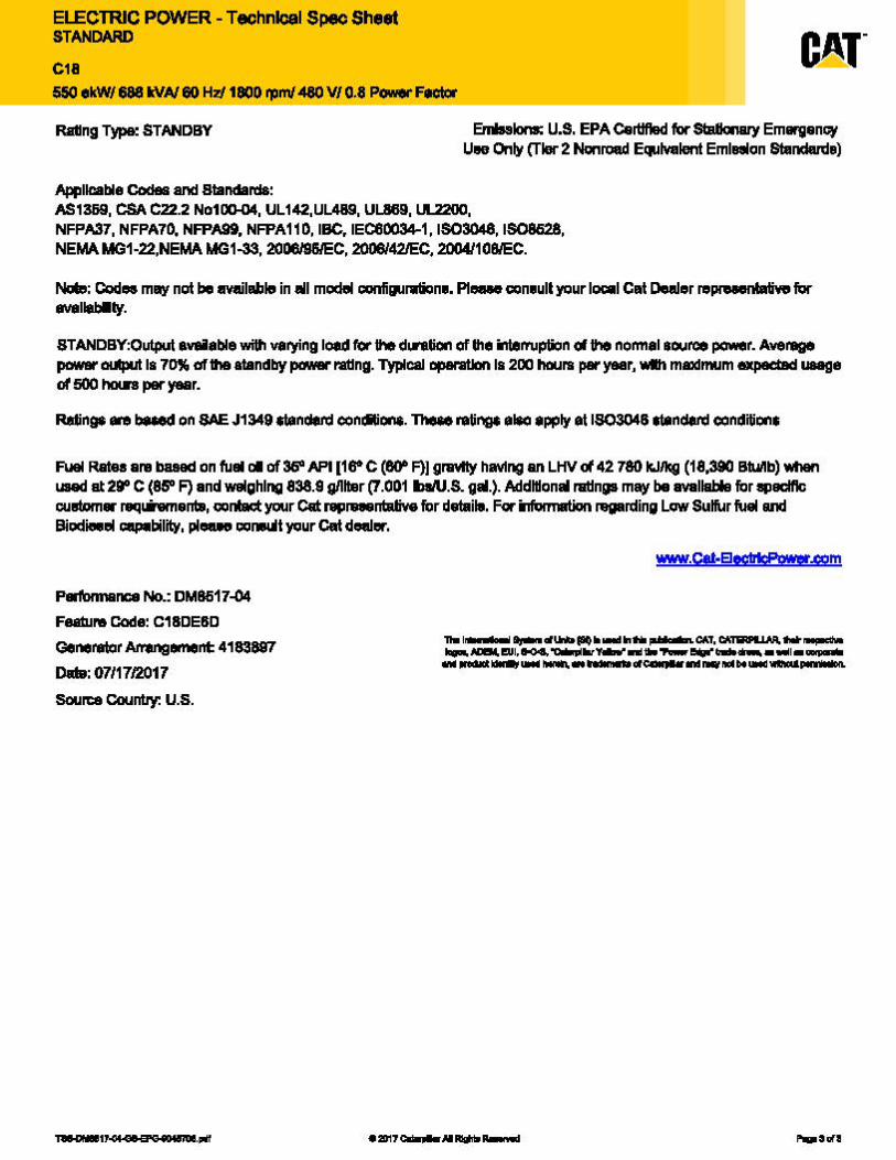
ELECTRIC POWER - Technlcal Spec Sheet STANDARD
C18 550 ekW/ 688 WA/ 80 HZ'/ 1800 ml -480 V/ 0.8 Power FIClor
Rllllng TW&! STANDBY
Appllcable Codee and Standard&:
Emlnlonl: U.S. EPA Certified far Siallon8ly Emarganc:y U119 Only (Tier 2 Nonroad Equivalent Emlnon Slandalde)
AS1359, CSA C22.2 No1D0-04, UL 142,UL489, UL..869, Ul..2200, NFPA37, NFPA70, NFPA9t, NFPA110, IBC, IEC60034-1, 1603048, IS081i28, NEMA MG1-22,NEMA MG1-33, 2008/HIEC, 2:006l42/EC, 2tl04110lll'EC.
NolD: Codes may not be available in all modlll iionfigurrion•. Pl-c:on•ull your IOl:lll Cat Dealer re11191elllatiwo far -llebmty.
STANDBY:Output available with varying load fot the d~tiol'I of Ille interruption of the noimal aource power. Average powar Olllpul Is 70% of Ille atandby power 11111ng. Typltal Dplll"atlon la 200 hours par year, v.1111 maximum expected 1M811• d 500 haln par year.
Ralinga ere beMd on SAE J1349 ctandetd con•ons. The8e ratings ei.o apply et 1803046 standatd conditiClllS
FUal Rataa ara ba&ad on fual DI of 369API11r C (80" F)J gnMty having an LHV d 42 780 kJJkG (18,390 Btu/lb) Yiilen Ull8d at 29" C (85" F) and weighing 838.8 g/lltar (7.001 lbl/U.S. gal.). Addltlonal rallnga may be avallable for 1111aclftc cuslom• 19q'*9manlll, contact your Cat rap.-ntative for dat.ill. For infvnnation regarding Lcnv Sulfur fuel and Biodilllel e!IP'lbility, pl-c:o..Wt your Cat dealer.
Pli"'1n18nca No.: DM8617-04
Femunt Code: C18DE6D
Generator Alrangement 4183887
Dal9: 07117/2D17
Source Countiy: U.S.
-n.1: .. 1 I ... 4't.tDllO~ ............. CAT. CAICU LUA. ........... --EUl.--llr-llllli.._.,.,.. ____ 11 __ ... ______ d ___ .,.l>t __ _
•:2011_,. __
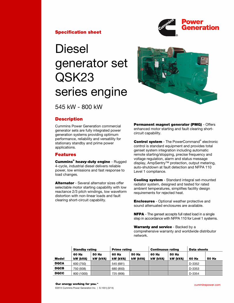
cumminspower.com ©2014 Cummins Power Generation Inc. | S-1551j (3/14)
Specification sheet
Diesel generator set QSK23 series engine 545 kW - 800 kW
Description Cummins Power Generation commercial generator sets are fully integrated power generation systems providing optimum performance, reliability and versatility for stationary standby and prime power applications.
Features
Cummins® heavy-duty engine - Rugged 4-cycle, industrial diesel delivers reliable power, low emissions and fast response to load changes. Alternator - Several alternator sizes offer selectable motor starting capability with low reactance 2/3 pitch windings, low waveform distortion with non-linear loads and fault clearing short-circuit capability.
Permanent magnet generator (PMG) - Offers enhanced motor starting and fault clearing short-circuit capability. Control system - The PowerCommand® electronic control is standard equipment and provides total genset system integration including automatic remote starting/stopping, precise frequency and voltage regulation, alarm and status message display, AmpSentry™ protection, output metering, auto-shutdown at fault detection and NFPA 110 Level 1 compliance. Cooling system - Standard integral set-mounted radiator system, designed and tested for rated ambient temperatures, simplifies facility design requirements for rejected heat. Enclosures - Optional weather protective and sound attenuated enclosures are available. NFPA - The genset accepts full rated load in a single step in accordance with NFPA 110 for Level 1 systems. Warranty and service - Backed by a comprehensive warranty and worldwide distributor network.
Standby rating Prime rating Continuous rating Data sheets
Model 60 Hz kW (kVA)
50 Hz kW (kVA)
60 Hz kW (kVA)
50 Hz kW (kVA)
60 Hz kW (kVA)
50 Hz kW (kVA) 60 Hz 50 Hz
DQCA 600 (750) 545 (681) D-3352
DQCB 750 (938) 680 (850) D-3353
DQCC 800 (1000) 725 (906) D-3354
fc002
Rectangle
fc002
Line
fc002
Line
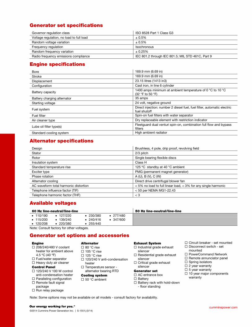
cumminspower.com ©2014 Cummins Power Generation Inc. | S-1551j (3/14)
Generator set specifications Governor regulation class ISO 8528 Part 1 Class G3 Voltage regulation, no load to full load ± 0.5% Random voltage variation ± 0.5% Frequency regulation Isochronous Random frequency variation ± 0.25% Radio frequency emissions compliance IEC 801.2 through IEC 801.5; MIL STD 461C, Part 9
Engine specifications Bore 169.9 mm (6.69 in)
Stroke 169.9 mm (6.69 in)
Displacement 23.15 litres (1413 in3)
Configuration Cast iron, in line 6 cylinder
Battery capacity 1400 amps minimum at ambient temperature of 0 °C to 10 °C (32 °F to 50 °F)
Battery charging alternator 35 amps
Starting voltage 24 volt, negative ground
Fuel system Direct injection: number 2 diesel fuel, fuel filter, automatic electric fuel shutoff
Fuel filter Spin-on fuel filters with water separator
Air cleaner type Dry replaceable element with restriction indicator
Lube oil filter type(s) Fleetguard dual venturi spin-on, combination full flow and bypass filters
Standard cooling system High ambient radiator
Alternator specifications Design Brushless, 4 pole, drip proof, revolving field Stator 2/3 pitch Rotor Single bearing flexible discs Insulation system Class H Standard temperature rise 125 ºC standby at 40 °C ambient Exciter type PMG (permanent magnet generator) Phase rotation A (U), B (V), C (W) Alternator cooling Direct drive centrifugal blower fan AC waveform total harmonic distortion < 5% no load to full linear load, < 3% for any single harmonic Telephone influence factor (TIF) < 50 per NEMA MG1-22.43 Telephone harmonic factor (THF) < 3
Available voltages
60 Hz line-neutral/line-line 50 Hz line-neutral/line-line • 110/190 • 115/200 • 120/208
• 127/220 • 139/240 • 220/380
• 230/380 • 240/416 • 255/440
• 277/480 • 347/600
Note: Consult factory for other voltages.
Generator set options and accessories
Engine 208/240/480 V coolant
heater for ambient above 4.5 ºC (40 ºF)
Fuel/water separator Heavy duty air cleaner Control Panel 120/240 V 100 W control
anti-condensation heater Paralleling configuration Remote fault signal
package Run relay package
Alternator 80 °C rise 105 °C rise 125 °C rise 120/240 V anti-condensation
heater Temperature sensor -
alternator bearing RTD Cooling system 50 °C ambient
Exhaust System Industrial grade exhaust
silencer Residential grade exhaust
silencer Critical grade exhaust
silencer Generator set AC entrance box Battery Battery rack with hold-down
- floor standing
Circuit breaker - set mounted Disconnect switch - set
mounted PowerCommand Network Remote annunciator panel Spring isolators 2 year warranty 5 year warranty 10 year major components
warranty
Note: Some options may not be available on all models - consult factory for availability.
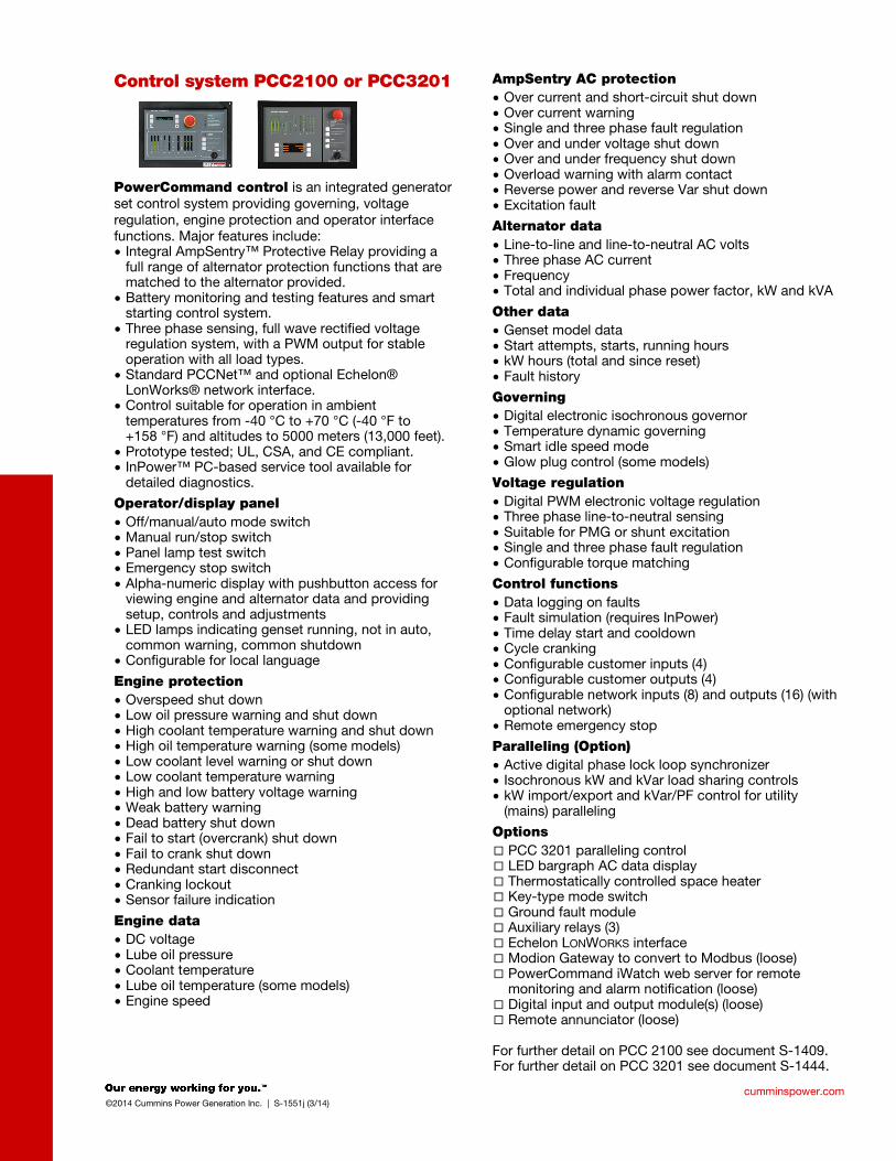
cumminspower.com ©2014 Cummins Power Generation Inc. | S-1551j (3/14)
Control system PCC2100 or PCC3201
PowerCommand control is an integrated generator set control system providing governing, voltage regulation, engine protection and operator interface functions. Major features include: • Integral AmpSentry™ Protective Relay providing a
full range of alternator protection functions that are matched to the alternator provided.
• Battery monitoring and testing features and smart starting control system.
• Three phase sensing, full wave rectified voltage regulation system, with a PWM output for stable operation with all load types.
• Standard PCCNet™ and optional Echelon® LonWorks® network interface.
• Control suitable for operation in ambient temperatures from -40 °C to +70 °C (-40 °F to +158 °F) and altitudes to 5000 meters (13,000 feet).
• Prototype tested; UL, CSA, and CE compliant. • InPower™ PC-based service tool available for
detailed diagnostics.
Operator/display panel • Off/manual/auto mode switch • Manual run/stop switch • Panel lamp test switch • Emergency stop switch • Alpha-numeric display with pushbutton access for
viewing engine and alternator data and providing setup, controls and adjustments
• LED lamps indicating genset running, not in auto, common warning, common shutdown
• Configurable for local language
Engine protection • Overspeed shut down • Low oil pressure warning and shut down • High coolant temperature warning and shut down • High oil temperature warning (some models) • Low coolant level warning or shut down • Low coolant temperature warning • High and low battery voltage warning • Weak battery warning • Dead battery shut down • Fail to start (overcrank) shut down • Fail to crank shut down • Redundant start disconnect • Cranking lockout • Sensor failure indication
Engine data • DC voltage • Lube oil pressure • Coolant temperature • Lube oil temperature (some models) • Engine speed
AmpSentry AC protection • Over current and short-circuit shut down • Over current warning • Single and three phase fault regulation • Over and under voltage shut down • Over and under frequency shut down • Overload warning with alarm contact • Reverse power and reverse Var shut down • Excitation fault
Alternator data • Line-to-line and line-to-neutral AC volts • Three phase AC current • Frequency • Total and individual phase power factor, kW and kVA
Other data • Genset model data • Start attempts, starts, running hours • kW hours (total and since reset) • Fault history
Governing • Digital electronic isochronous governor • Temperature dynamic governing • Smart idle speed mode • Glow plug control (some models)
Voltage regulation • Digital PWM electronic voltage regulation • Three phase line-to-neutral sensing • Suitable for PMG or shunt excitation • Single and three phase fault regulation • Configurable torque matching
Control functions • Data logging on faults • Fault simulation (requires InPower) • Time delay start and cooldown • Cycle cranking • Configurable customer inputs (4) • Configurable customer outputs (4) • Configurable network inputs (8) and outputs (16) (with
optional network) • Remote emergency stop
Paralleling (Option) • Active digital phase lock loop synchronizer • Isochronous kW and kVar load sharing controls • kW import/export and kVar/PF control for utility
(mains) paralleling
Options PCC 3201 paralleling control LED bargraph AC data display Thermostatically controlled space heater Key-type mode switch Ground fault module Auxiliary relays (3) Echelon LONWORKS interface Modion Gateway to convert to Modbus (loose) PowerCommand iWatch web server for remote
monitoring and alarm notification (loose) Digital input and output module(s) (loose) Remote annunciator (loose)
For further detail on PCC 2100 see document S-1409. For further detail on PCC 3201 see document S-1444.
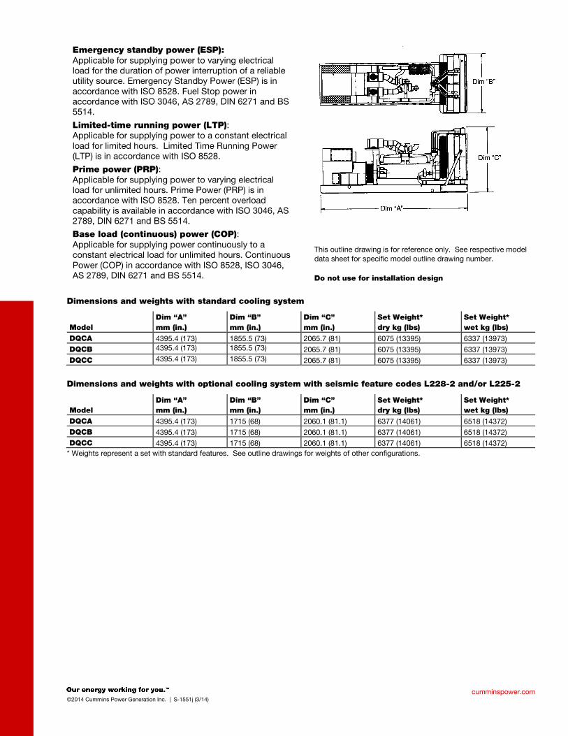
cumminspower.com ©2014 Cummins Power Generation Inc. | S-1551j (3/14)
Emergency standby power (ESP): Applicable for supplying power to varying electrical load for the duration of power interruption of a reliable utility source. Emergency Standby Power (ESP) is in accordance with ISO 8528. Fuel Stop power in accordance with ISO 3046, AS 2789, DIN 6271 and BS 5514.
Limited-time running power (LTP): Applicable for supplying power to a constant electrical load for limited hours. Limited Time Running Power (LTP) is in accordance with ISO 8528.
Prime power (PRP): Applicable for supplying power to varying electrical load for unlimited hours. Prime Power (PRP) is in accordance with ISO 8528. Ten percent overload capability is available in accordance with ISO 3046, AS 2789, DIN 6271 and BS 5514.
Base load (continuous) power (COP): Applicable for supplying power continuously to a constant electrical load for unlimited hours. Continuous Power (COP) in accordance with ISO 8528, ISO 3046, AS 2789, DIN 6271 and BS 5514.
This outline drawing is for reference only. See respective model data sheet for specific model outline drawing number. Do not use for installation design
Dimensions and weights with standard cooling system
Model Dim “A” mm (in.)
Dim “B” mm (in.)
Dim “C” mm (in.)
Set Weight* dry kg (lbs)
Set Weight* wet kg (lbs)
DQCA 4395.4 (173) 1855.5 (73) 2065.7 (81) 6075 (13395) 6337 (13973) DQCB 4395.4 (173) 1855.5 (73) 2065.7 (81) 6075 (13395) 6337 (13973) DQCC 4395.4 (173) 1855.5 (73) 2065.7 (81) 6075 (13395) 6337 (13973)
Dimensions and weights with optional cooling system with seismic feature codes L228-2 and/or L225-2
Model Dim “A” mm (in.)
Dim “B” mm (in.)
Dim “C” mm (in.)
Set Weight* dry kg (lbs)
Set Weight* wet kg (lbs)
DQCA 4395.4 (173) 1715 (68) 2060.1 (81.1) 6377 (14061) 6518 (14372) DQCB 4395.4 (173) 1715 (68) 2060.1 (81.1) 6377 (14061) 6518 (14372) DQCC 4395.4 (173) 1715 (68) 2060.1 (81.1) 6377 (14061) 6518 (14372)
* Weights represent a set with standard features. See outline drawings for weights of other configurations.
fc002
Rectangle
fc002
Line
fc002
Rectangle
fc002
Line
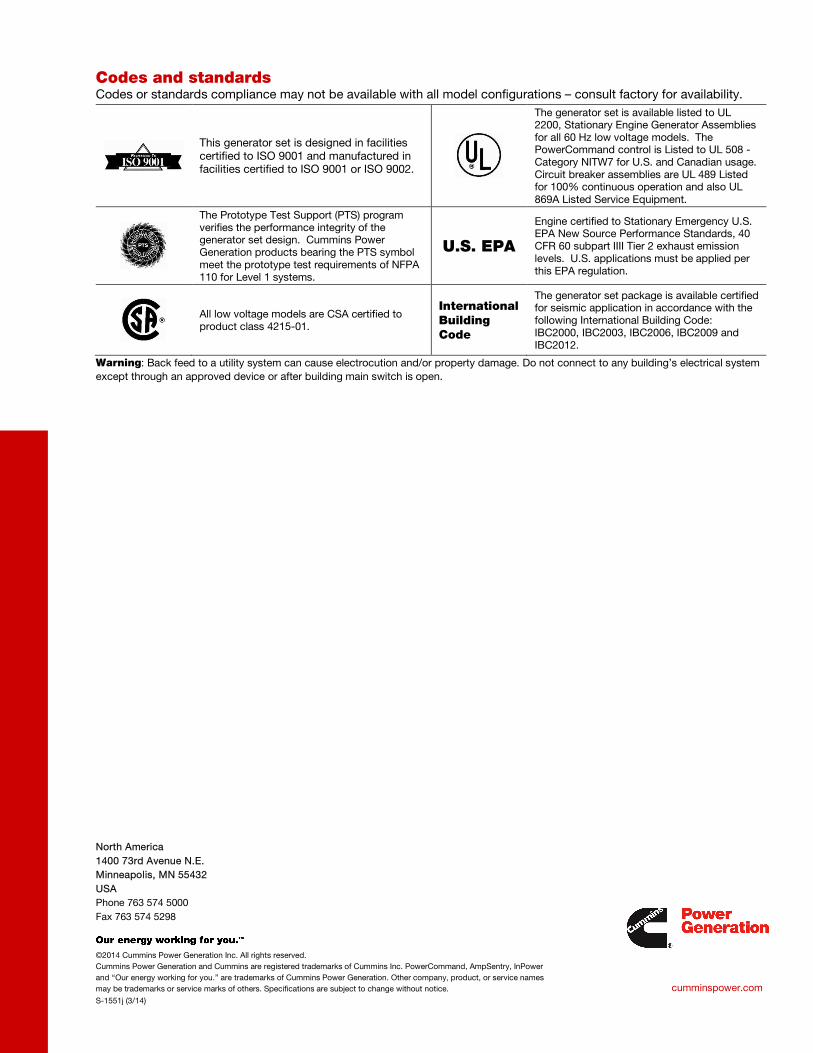
North America 1400 73rd Avenue N.E. Minneapolis, MN 55432 USA Phone 763 574 5000 Fax 763 574 5298
©2014 Cummins Power Generation Inc. All rights reserved. Cummins Power Generation and Cummins are registered trademarks of Cummins Inc. PowerCommand, AmpSentry, InPower and “Our energy working for you.” are trademarks of Cummins Power Generation. Other company, product, or service names may be trademarks or service marks of others. Specifications are subject to change without notice.
S-1551j (3/14)
cumminspower.com
Codes and standards Codes or standards compliance may not be available with all model configurations – consult factory for availability.
This generator set is designed in facilities certified to ISO 9001 and manufactured in facilities certified to ISO 9001 or ISO 9002.
The generator set is available listed to UL 2200, Stationary Engine Generator Assemblies for all 60 Hz low voltage models. The PowerCommand control is Listed to UL 508 - Category NITW7 for U.S. and Canadian usage. Circuit breaker assemblies are UL 489 Listed for 100% continuous operation and also UL 869A Listed Service Equipment.
The Prototype Test Support (PTS) program verifies the performance integrity of the generator set design. Cummins Power Generation products bearing the PTS symbol meet the prototype test requirements of NFPA 110 for Level 1 systems.
U.S. EPA
Engine certified to Stationary Emergency U.S. EPA New Source Performance Standards, 40 CFR 60 subpart IIII Tier 2 exhaust emission levels. U.S. applications must be applied per this EPA regulation.
All low voltage models are CSA certified to product class 4215-01.
International Building Code
The generator set package is available certified for seismic application in accordance with the following International Building Code: IBC2000, IBC2003, IBC2006, IBC2009 and IBC2012.
Warning: Back feed to a utility system can cause electrocution and/or property damage. Do not connect to any building’s electrical system except through an approved device or after building main switch is open.
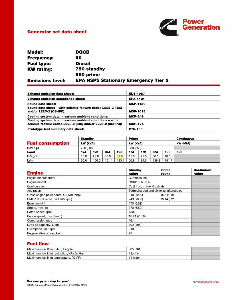
cumminspower.com ©2014 Cummins Power Generation Inc. | D-3353h (3/14)
Generator set data sheet
Model: Frequency: Fuel type: KW rating:
Emissions level:
DQCB 60 Diesel 750 standby 680 prime EPA NSPS Stationary Emergency Tier 2
Exhaust emission data sheet: EDS-1087
Exhaust emission compliance sheet: EPA-1121
Sound data sheet: MSP-1159 Sound data sheet – with seismic feature codes L228-2 (IBC) and/or L225-2 (OSHPD): MSP-1013
Cooling system data in various ambient conditions: MCP-248 Cooling system data in various ambient conditions – with seismic feature codes L228-2 (IBC) and/or L225-2 (OSHPD): MCP-174
Prototype test summary data sheet: PTS-160
Fuel consumption Standby Prime Continuous
kW (kVA) kW (kVA) kW (kVA)
Ratings 750 (938) 680 (850) Load 1/4 1/2 3/4 Full 1/4 1/2 3/4 Full Full US gph 16.0 28.0 40.0 51.0 15.0 25.0 36.5 48.0 L/hr 60.6 106.0 151.4 193.1 56.8 94.6 138.2 181.7
Engine Standby rating
Prime rating
Continuous rating
Engine manufacturer Cummins Inc. Engine model QSK23-G7 NR2 Configuration Cast Iron, in line, 6 cylinder Aspiration Turbocharged and air-to-air aftercooled Gross engine power output, kWm (bhp) 910 (1220) 808 (1085) BMEP at set rated load, kPa (psi) 2435 (353) 2214 (321) Bore, mm (in) 170 (6.69) Stroke, mm (in) 170 (6.69) Rated speed, rpm 1800 Piston speed, m/s (ft/min) 10.21 (2010) Compression ratio 16:1 Lube oil capacity, L (qt) 102 (108) Overspeed limit, rpm 2100 Regenerative power, kW 93
Fuel flow Maximum fuel flow, L/hr (US gph) 685 (181) Maximum fuel inlet restriction, kPa (in Hg) 13.44 (4) Maximum fuel inlet temperature, °C (°F) 71 (160)
fc002
Rectangle
fc002
Line
fc002
Highlight
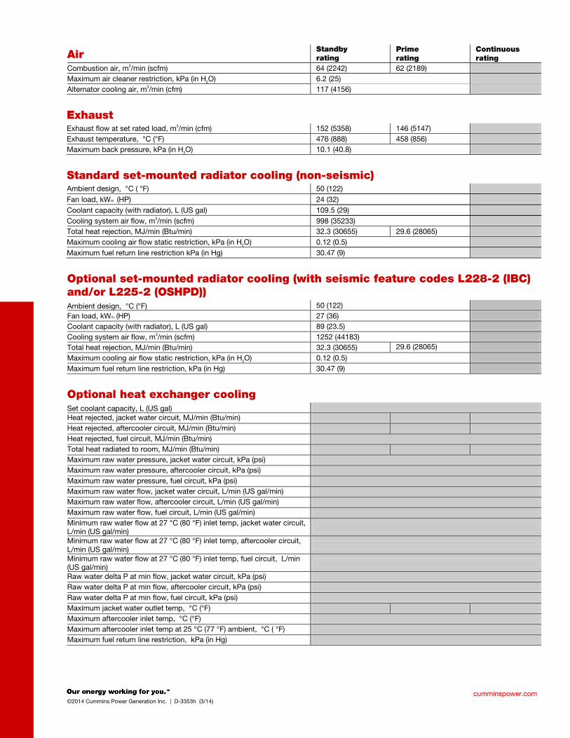
cumminspower.com ©2014 Cummins Power Generation Inc. | D-3353h (3/14)
Air Standby rating
Prime rating
Continuous rating
Combustion air, m3/min (scfm) 64 (2242) 62 (2189)
Maximum air cleaner restriction, kPa (in H2O) 6.2 (25)
Alternator cooling air, m3/min (cfm) 117 (4156)
Exhaust
Exhaust flow at set rated load, m3/min (cfm) 152 (5358) 146 (5147)
Exhaust temperature, °C (°F) 476 (888) 458 (856)
Maximum back pressure, kPa (in H2O) 10.1 (40.8)
Standard set-mounted radiator cooling (non-seismic) Ambient design, °C ( °F) 50 (122)
Fan load, kWm (HP) 24 (32)
Coolant capacity (with radiator), L (US gal) 109.5 (29)
Cooling system air flow, m3/min (scfm) 998 (35233)
Total heat rejection, MJ/min (Btu/min) 32.3 (30655) 29.6 (28065)
Maximum cooling air flow static restriction, kPa (in H2O) 0.12 (0.5)
Maximum fuel return line restriction kPa (in Hg) 30.47 (9)
Optional set-mounted radiator cooling (with seismic feature codes L228-2 (IBC) and/or L225-2 (OSHPD)) Ambient design, °C (°F) 50 (122)
Fan load, kWm (HP) 27 (36)
Coolant capacity (with radiator), L (US gal) 89 (23.5)
Cooling system air flow, m3/min (scfm) 1252 (44183)
Total heat rejection, MJ/min (Btu/min) 32.3 (30655) 29.6 (28065)
Maximum cooling air flow static restriction, kPa (in H2O) 0.12 (0.5)
Maximum fuel return line restriction, kPa (in Hg) 30.47 (9)
Optional heat exchanger cooling
Set coolant capacity, L (US gal) Heat rejected, jacket water circuit, MJ/min (Btu/min) Heat rejected, aftercooler circuit, MJ/min (Btu/min) Heat rejected, fuel circuit, MJ/min (Btu/min) Total heat radiated to room, MJ/min (Btu/min) Maximum raw water pressure, jacket water circuit, kPa (psi) Maximum raw water pressure, aftercooler circuit, kPa (psi) Maximum raw water pressure, fuel circuit, kPa (psi) Maximum raw water flow, jacket water circuit, L/min (US gal/min) Maximum raw water flow, aftercooler circuit, L/min (US gal/min) Maximum raw water flow, fuel circuit, L/min (US gal/min) Minimum raw water flow at 27 °C (80 °F) inlet temp, jacket water circuit, L/min (US gal/min)
Minimum raw water flow at 27 °C (80 °F) inlet temp, aftercooler circuit, L/min (US gal/min)
Minimum raw water flow at 27 °C (80 °F) inlet temp, fuel circuit, L/min (US gal/min)
Raw water delta P at min flow, jacket water circuit, kPa (psi) Raw water delta P at min flow, aftercooler circuit, kPa (psi) Raw water delta P at min flow, fuel circuit, kPa (psi) Maximum jacket water outlet temp, °C (°F) Maximum aftercooler inlet temp, °C (°F) Maximum aftercooler inlet temp at 25 °C (77 °F) ambient, °C ( °F) Maximum fuel return line restriction, kPa (in Hg)
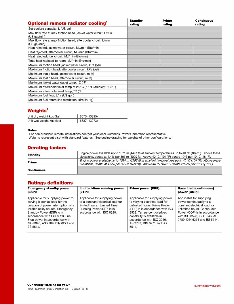
cumminspower.com ©2014 Cummins Power Generation Inc. | D-3353h (3/14)
Optional remote radiator cooling1 Standby rating
Prime rating
Continuous rating
Set coolant capacity, L (US gal)
Max flow rate at max friction head, jacket water circuit, L/min (US gal/min)
Max flow rate at max friction head, aftercooler circuit, L/min (US gal/min)
Heat rejected, jacket water circuit, MJ/min (Btu/min)
Heat rejected, aftercooler circuit, MJ/min (Btu/min) Heat rejected, fuel circuit, MJ/min (Btu/min) Total heat radiated to room, MJ/min (Btu/min)
Maximum friction head, jacket water circuit, kPa (psi) Maximum friction head, aftercooler circuit, kPa (psi)
Maximum static head, jacket water circuit, m (ft) Maximum static head, aftercooler circuit, m (ft)
Maximum jacket water outlet temp, °C (°F) Maximum aftercooler inlet temp at 25 °C (77 °F) ambient, °C (°F) Maximum aftercooler inlet temp, °C (°F) Maximum fuel flow, L/hr (US gph) Maximum fuel return line restriction, kPa (in Hg)
Weights2
Unit dry weight kgs (lbs) 6075 (13395) Unit wet weight kgs (lbs) 6337 (13973)
Notes: 1 For non-standard remote installations contact your local Cummins Power Generation representative. 2 Weights represent a set with standard features. See outline drawing for weights of other configurations.
Derating factors
Standby Engine power available up to 1371 m (4497 ft) at ambient temperatures up to 40 °C (104 °F). Above these elevations, derate at 4.4% per 305 m (1000 ft). Above 40 °C (104 °F) derate 10% per 10 °C (18 °F).
Prime Engine power available up to 1084 m (3555 ft) at ambient temperatures up to 40 °C (104 °F). Above these elevations, derate at 4.5% per 305 m (1000 ft). Above 40 °C (104 °F) derate 20.9% per 10 °C (18 °F).
Continuous
Ratings definitions
Emergency standby power (ESP):
Limited-time running power (LTP):
Prime power (PRP):
Base load (continuous) power (COP):
Applicable for supplying power to varying electrical load for the duration of power interruption of a reliable utility source. Emergency Standby Power (ESP) is in accordance with ISO 8528. Fuel Stop power in accordance with ISO 3046, AS 2789, DIN 6271 and BS 5514.
Applicable for supplying power to a constant electrical load for limited hours. Limited Time Running Power (LTP) is in accordance with ISO 8528.
Applicable for supplying power to varying electrical load for unlimited hours. Prime Power (PRP) is in accordance with ISO 8528. Ten percent overload capability is available in accordance with ISO 3046, AS 2789, DIN 6271 and BS 5514.
Applicable for supplying power continuously to a constant electrical load for unlimited hours. Continuous Power (COP) is in accordance with ISO 8528, ISO 3046, AS 2789, DIN 6271 and BS 5514.
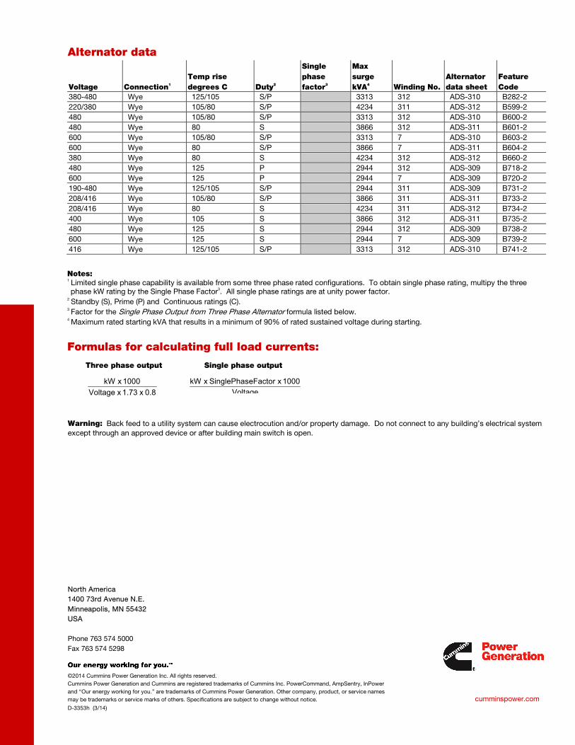
North America 1400 73rd Avenue N.E. Minneapolis, MN 55432 USA Phone 763 574 5000 Fax 763 574 5298
©2014 Cummins Power Generation Inc. All rights reserved. Cummins Power Generation and Cummins are registered trademarks of Cummins Inc. PowerCommand, AmpSentry, InPower and “Our energy working for you.” are trademarks of Cummins Power Generation. Other company, product, or service names may be trademarks or service marks of others. Specifications are subject to change without notice.
D-3353h (3/14)
cumminspower.com
Alternator data
Voltage Connection1 Temp rise degrees C Duty2
Single phase factor3
Max surge kVA4 Winding No.
Alternator data sheet
Feature Code
380-480 Wye 125/105 S/P 3313 312 ADS-310 B282-2 220/380 Wye 105/80 S/P 4234 311 ADS-312 B599-2 480 Wye 105/80 S/P 3313 312 ADS-310 B600-2 480 Wye 80 S 3866 312 ADS-311 B601-2 600 Wye 105/80 S/P 3313 7 ADS-310 B603-2 600 Wye 80 S/P 3866 7 ADS-311 B604-2 380 Wye 80 S 4234 312 ADS-312 B660-2 480 Wye 125 P 2944 312 ADS-309 B718-2 600 Wye 125 P 2944 7 ADS-309 B720-2 190-480 Wye 125/105 S/P 2944 311 ADS-309 B731-2 208/416 Wye 105/80 S/P 3866 311 ADS-311 B733-2 208/416 Wye 80 S 4234 311 ADS-312 B734-2 400 Wye 105 S 3866 312 ADS-311 B735-2 480 Wye 125 S 2944 312 ADS-309 B738-2 600 Wye 125 S 2944 7 ADS-309 B739-2 416 Wye 125/105 S/P 3313 312 ADS-310 B741-2
Notes: 1 Limited single phase capability is available from some three phase rated configurations. To obtain single phase rating, multipy the three phase kW rating by the Single Phase Factor3. All single phase ratings are at unity power factor.
2 Standby (S), Prime (P) and Continuous ratings (C).
3 Factor for the Single Phase Output from Three Phase Alternator formula listed below.
4 Maximum rated starting kVA that results in a minimum of 90% of rated sustained voltage during starting.
Formulas for calculating full load currents:
Three phase output Single phase output
Warning: Back feed to a utility system can cause electrocution and/or property damage. Do not connect to any building’s electrical system except through an approved device or after building main switch is open.
Voltage1000 x eFactorSinglePhas x kW
0.8 x 1.73 x Voltage
1000 x kW

Our energy working for you.™
www.cumminspower.com 2014 Cummins Power Generation Inc. All rights reserved. Cummins Power Generation and Cummins are registered trademarks of Cummins Inc. PowerCommand and “Our energy working for you.” are trademarks of Cummins Power Generation. Specifications are subject to change without notice. S-1443z (9/14)
Enclosures and tanks 250-1000 kW gensets
Enclosure standard features • 14-gauge steel construction (panels)• Stainless steel hardware• Zinc phosphate pretreatment, e-coat primer and super
durable powder topcoat paint minimize corrosion andcolor fade
• Package listed to UL 2200• Designed to satisfy National Electrical Code installation
requirements• Fuel and electrical stub-up area within enclosure
perimeter• Fixed louvers• Cambered roof prevents water accumulation• Recessed, lockable doors in two sides• Retainers hold doors open for easy access• Enclosed exhaust silencer ensures safety and protects
against rust• Rain cap• Exterior oil and coolant drains with interior valves for
ease of service• Rodent barriers on inlet• Non-hydroscopic sound attenuating material• Side mounted controls and circuit breakers• Easy access lifting points for spreader bars• Dual vibration isolation system (250-500 kW)• Spring vibration isolation system (600-1000 kW)• Enclosure mounts to lifting base or fuel tank
(250-500 kW)• Enclosure mounts to lifting base (600-1000 kW)• Factory pre-assembled package• Designed for outdoor use only• Externally mounted emergency stop button for
operator safety (optional on 250-500 kW)• Horizontal air discharge to prevent leaf and snow
accumulation (600-1000 kW)
Options • Three levels of sound attenuation• Motorized louvers to protect from ice and snow
accumulation (available on air inlet for all models andon air outlet on level II, 250-500 kW enclosures only)
• Horizontal air discharge, sound level 2 only(250-500 kW)
• Aluminum construction with roll-coated polymer paint• Wind rated to 150 mph• Neutral sandstone paint color• Factory mounted battery charger• External 120 VAC service outlet• Rain hoods for air inlet (250-500 kW)• Lifting base in lieu of a sub-base tank (250-500 kW)
- Pre-wired AC distribution package - 100 amp (250-500 kW) or 150 amp (600-1000 kW)
main circuit breaker; connected to 120 VAC line-neutral and 208 or 240 VAC line-line, spare breaker positions and capacity for future upgrades (600-1000 kW)
- GFCI protected internal 120 VAC service receptacle - GFCI protected weather proof external 120 volt
service receptacle - All factory installed AC powered features pre-wired
into load center • Interior lights – 120 volt (600-1000 kW)• Rain hoods for air inlet (250-500 kW)• Seismic isolators available (600-1000 kW)

Our energy working for you.™
www.cumminspower.com 2014 Cummins Power Generation Inc. All rights reserved. Cummins Power Generation and Cummins are registered trademarks of Cummins Inc. PowerCommand and “Our energy working for you.” are trademarks of Cummins Power Generation. Specifications are subject to change without notice. S-1443z (9/14)
Fuel tanks Standard sub-base tank features
• UL 142 Listed • ULC-S601-07 Listed • NFPA37 compliant • Dual walled, steel construction • Emergency tank and rupture basin vents • Tank mounted mechanical fuel gauge • Fuel supply and return tubes • Top mounted leak detection float switch • Low and high level fuel switches • Mounting brackets for optional pump and control
(250-500 kW) • Integral lifting points
Sub-base tank options
• Pre-wired fuel pump and control • Fuel overfill alarm – internal or external • Overflow and tank fill plugs • Five gallon spill fill box – internal or external • Fill pipe extender • Local code approvals available
200-500 kW dual wall sub-base fuel tanks – usable operating hours Genset model (60 Hz)
Gallons/hour at full load
270 gallon tank
300 gallon tank
400 gallon tank
500 gallon tank
600 gallon tank
660 gallon tank
720 gallon tank
850 gallon tank
1420 gallon tank
1470 gallon tank
1700 gallon tank
2050 gallon tank
2525 gallon tank
250 DQDAA 20 14 15 20 25 30 33 36 72 74 104 275 DQDAB 21 13 14 19 24 29 31 34 66 70 96 300 DQDAC 23 12 13 17 22 26 29 31 61 64 88 300 DQHAB 23 12 13 17 22 26 29 37 74 450 DFEJ 30 9 10 13 17 20 22 28 57 84 500 DFEK 34 8 9 11 15 18 19 25 50 74
Operating hours are measured at 60 Hz, standby rating.
600-1000 kW dual wall sub-base fuel tanks – usable operating hours
Genset model
Gallons/hour at full load
200 gallon tank
660 gallon tank
1000 gallon tank
1500 gallon tank
2000 gallon tank
2400 gallon tank
600 DQCA 42 5 16 24 36 48 57 600 DQPAA 45 4 15 22 33 44 53 650 DQPAB 50 4 13 20 30 40 48 750 DQCB 51 4 13 20 29 39 47 750 DQFAA 53 4 12 19 28 38 45 800 DQCC 53 4 12 19 28 38 45 800 DQFAB 56 4 12 18 27 36 43 900 DQFAC 64 3 10 16 23 31 38 1000 DQFAD 72 3 9 14 21 28 33
*3000 gallon tank offered as an accessory kit – refer to NAAC-5853 spec sheet
- Operating hours are measured at 60Hz, standby rating. - Up to 90% fill alarm to comply with NFPA30, operating capacity is reduced by 10%.
fc002
Line
fc002
Rectangle
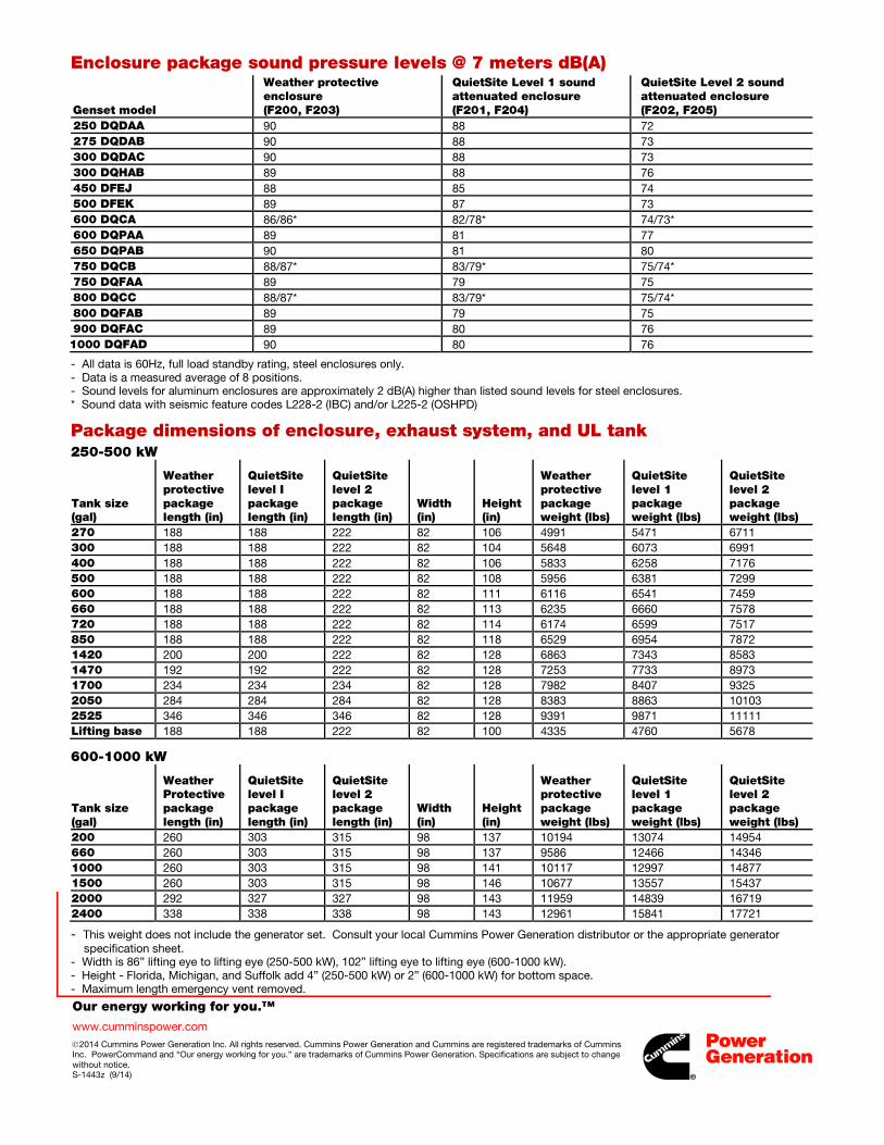
.
Our energy working for you.™
www.cumminspower.com 2014 Cummins Power Generation Inc. All rights reserved. Cummins Power Generation and Cummins are registered trademarks of Cummins Inc. PowerCommand and “Our energy working for you.” are trademarks of Cummins Power Generation. Specifications are subject to change without notice. S-1443z (9/14)
Enclosure package sound pressure levels @ 7 meters dB(A)
Genset model
Weather protective enclosure (F200, F203)
QuietSite Level 1 sound attenuated enclosure (F201, F204)
QuietSite Level 2 sound attenuated enclosure (F202, F205)
250 DQDAA 90 88 72 275 DQDAB 90 88 73 300 DQDAC 90 88 73 300 DQHAB 89 88 76 450 DFEJ 88 85 74 500 DFEK 89 87 73 600 DQCA 86/86* 82/78* 74/73* 600 DQPAA 89 81 77 650 DQPAB 90 81 80 750 DQCB 88/87* 83/79* 75/74* 750 DQFAA 89 79 75 800 DQCC 88/87* 83/79* 75/74* 800 DQFAB 89 79 75 900 DQFAC 89 80 76 1000 DQFAD 90 80 76
- All data is 60Hz, full load standby rating, steel enclosures only. - Data is a measured average of 8 positions. - Sound levels for aluminum enclosures are approximately 2 dB(A) higher than listed sound levels for steel enclosures. * Sound data with seismic feature codes L228-2 (IBC) and/or L225-2 (OSHPD)
Package dimensions of enclosure, exhaust system, and UL tank 250-500 kW
Tank size (gal)
Weather protective package length (in)
QuietSite level I package length (in)
QuietSite level 2 package length (in)
Width (in)
Height (in)
Weather protective package weight (lbs)
QuietSite level 1 package weight (lbs)
QuietSite level 2 package weight (lbs)
270 188 188 222 82 106 4991 5471 6711 300 188 188 222 82 104 5648 6073 6991 400 188 188 222 82 106 5833 6258 7176 500 188 188 222 82 108 5956 6381 7299 600 188 188 222 82 111 6116 6541 7459 660 188 188 222 82 113 6235 6660 7578 720 188 188 222 82 114 6174 6599 7517 850 188 188 222 82 118 6529 6954 7872 1420 200 200 222 82 128 6863 7343 8583 1470 192 192 222 82 128 7253 7733 8973 1700 234 234 234 82 128 7982 8407 9325 2050 284 284 284 82 128 8383 8863 10103 2525 346 346 346 82 128 9391 9871 11111 Lifting base 188 188 222 82 100 4335 4760 5678
600-1000 kW
Tank size (gal)
Weather Protective package length (in)
QuietSite level I package length (in)
QuietSite level 2 package length (in)
Width (in)
Height (in)
Weather protective package weight (lbs)
QuietSite level 1 package weight (lbs)
QuietSite level 2 package weight (lbs)
200 260 303 315 98 137 10194 13074 14954 660 260 303 315 98 137 9586 12466 14346 1000 260 303 315 98 141 10117 12997 14877 1500 260 303 315 98 146 10677 13557 15437 2000 292 327 327 98 143 11959 14839 16719 2400 338 338 338 98 143 12961 15841 17721
- This weight does not include the generator set. Consult your local Cummins Power Generation distributor or the appropriate generator specification sheet.
- Width is 86” lifting eye to lifting eye (250-500 kW), 102” lifting eye to lifting eye (600-1000 kW). - Height - Florida, Michigan, and Suffolk add 4” (250-500 kW) or 2” (600-1000 kW) for bottom space. - Maximum length emergency vent removed.
fc002
Rectangle
fc002
Line
fc002
Rectangle
.
Our energy working for you.™
www.cumminspower.com 2014 Cummins Power Generation Inc. All rights reserved. Cummins Power Generation and Cummins are registered trademarks of Cummins Inc. PowerCommand and “Our energy working for you.” are trademarks of Cummins Power Generation. Specifications are subject to change without notice. S-1443z (9/14)
CSA - The generator set is CSA certified to product class 4215-01.
UL - The generator set is available Listed to UL 2200, Stationary Engine Generator Assemblies. The PowerCommand control is Listed to UL 508 - Category NITW7 for U.S. and Canadian usage.
See your distributor for more information Americas 1400 73rd Avenue N.E. Minneapolis, MN 55432 USA Phone: 763 574-5000 Fax: 763 574-5298
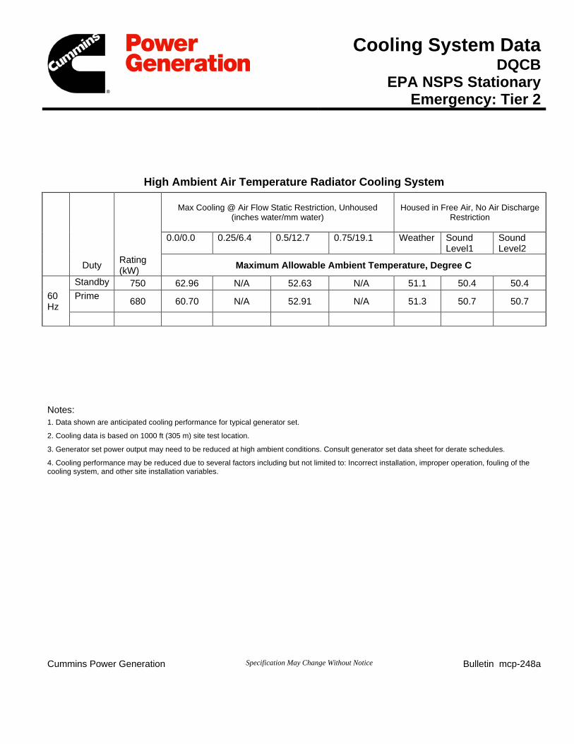
Cooling System Data DQCB
EPA NSPS Stationary Emergency: Tier 2
High Ambient Air Temperature Radiator Cooling System
Max Cooling @ Air Flow Static Restriction, Unhoused (inches water/mm water)
Housed in Free Air, No Air Discharge Restriction
0.0/0.0 0.25/6.4 0.5/12.7 0.75/19.1 Weather Sound Level1
Sound Level2
Duty Rating (kW) Maximum Allowable Ambient Temperature, Degree C
Standby 750 62.96 N/A 52.63 N/A 51.1 50.4 50.4 60 Hz
Prime 680 60.70 N/A 52.91 N/A 51.3 50.7 50.7
Notes: 1. Data shown are anticipated cooling performance for typical generator set.
2. Cooling data is based on 1000 ft (305 m) site test location.
3. Generator set power output may need to be reduced at high ambient conditions. Consult generator set data sheet for derate schedules.
4. Cooling performance may be reduced due to several factors including but not limited to: Incorrect installation, improper operation, fouling of the cooling system, and other site installation variables.
Cummins Power Generation Specification May Change Without Notice Bulletin mcp-248a
fc002
Rectangle
fc002
Line
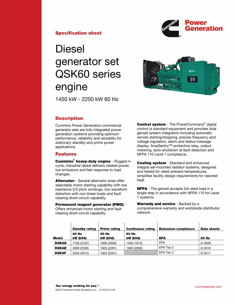
cumminspower.com ©2013 Cummins Power Generation Inc. | S-1627d (1/13)
Specification sheet
Diesel generator set QSK60 series engine 1450 kW - 2250 kW 60 Hz
Description Cummins Power Generation commercial generator sets are fully integrated power generation systems providing optimum performance, reliability and versatility for stationary standby and prime power applications.
Features
Cummins® heavy-duty engine - Rugged 4-cycle, industrial diesel delivers reliable power, low emissions and fast response to load changes.
Alternator - Several alternator sizes offer selectable motor starting capability with low reactance 2/3 pitch windings, low waveform distortion with non-linear loads and fault clearing short-circuit capability.
Permanent magnet generator (PMG) - Offers enhanced motor starting and fault clearing short-circuit capability.
Control system - The PowerCommand® digital control is standard equipment and provides total genset system integration including automatic remote starting/stopping, precise frequency and voltage regulation, alarm and status message display, AmpSentry™ protective relay, output metering, auto-shutdown at fault detection and NFPA 110 Level 1 compliance. Cooling system - Standard and enhanced integral set-mounted radiator systems, designed and tested for rated ambient temperatures, simplifies facility design requirements for rejected heat. NFPA - The genset accepts full rated load in a single step in accordance with NFPA 110 for Level 1 systems.
Warranty and service - Backed by a comprehensive warranty and worldwide distributor network.
Standby rating Prime rating Continuous rating Emissions compliance Data sheets
Model 60 Hz kW (kVA)
60 Hz kW (kVA)
60 Hz kW (kVA) EPA 60 Hz
DQKAD 1750 (2187) 1600 (2000) 1450 (1812) EPA D-3509
DQKAE 2000 (2500) 1825 (2281) 1600 (2000) EPA Tier 2 D-3510
DQKAF 2250 (2812) 1825 (2281) EPA Tier 2 D-3511
fc002
Rectangle
fc002
Line
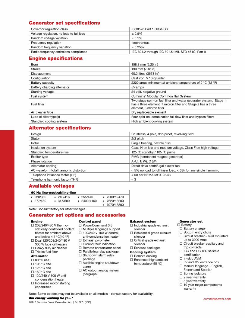
cumminspower.com ©2013 Cummins Power Generation Inc. | S-1627d (1/13)
Generator set specifications Governor regulation class ISO8528 Part 1 Class G3 Voltage regulation, no load to full load ± 0.5% Random voltage variation ± 0.5% Frequency regulation Isochronous Random frequency variation ± 0.25% Radio frequency emissions compliance IEC 801.2 through IEC 801.5; MIL STD 461C, Part 9
Engine specifications Bore 158.8 mm (6.25 in) Stroke 190 mm (7.48 in) Displacement 60.2 litres (3673 in3) Configuration Cast iron, V 16 cylinder Battery capacity 2200 amps minimum at ambient temperature of 0 °C (32 °F) Battery charging alternator 55 amps Starting voltage 24 volt, negative ground Fuel system Cummins’ Modular Common Rail System
Fuel filter Two stage spin-on fuel filter and water separator system. Stage 1 has a three element, 7 micron filter and Stage 2 has a three element, 3 micron filter.
Air cleaner type Dry replaceable element Lube oil filter type(s) Four spin-on, combination full flow filter and bypass filters Standard cooling system High ambient cooling system
Alternator specifications Design Brushless, 4 pole, drip proof, revolving field Stator 2/3 pitch Rotor Single bearing, flexible disc Insulation system Class H on low and medium voltage, Class F on high voltage Standard temperature rise 125 ºC standby / 105 ºC prime Exciter type PMG (permanent magnet generator) Phase rotation A (U), B (V), C (W) Alternator cooling Direct drive centrifugal blower fan AC waveform total harmonic distortion < 5% no load to full linear load, < 3% for any single harmonic Telephone influence factor (TIF) < 50 per NEMA MG1-22.43 Telephone harmonic factor (THF) < 3
Available voltages 60 Hz line-neutral/line-line • 220/380 • 277/480
• 240/416 • 347/600
• 255/440 • 2400/4160
• 7200/12470 • 7620/13200 • 7970/13800
Note: Consult factory for other voltages.
Generator set options and accessories Engine 208/240/480 V thermo-
statically controlled coolant heater for ambient above and below 4.5 °C(40 °F)
Dual 120/208/240/480 V 300 W lube oil heaters
Heavy duty air cleaner Triplex fuel filter Alternator 80 °C rise 105 °C rise 125 °C rise 150 °C rise 120/240 V 300 W anti-
condensation heater Increased motor starting
capabilities
Control panel PowerCommand 3.3 Multiple language support 120/240 V 100 W control
anti-condensation heater Exhaust pyrometer Ground fault indication Remote annunciator panel Paralleling relay package Shutdown alarm relay
package Audible engine shutdown
alarm AC output analog meters
(bargraph)
Exhaust system Industrial grade exhaust
silencer Residential grade exhaust
silencer Critical grade exhaust
silencer Exhaust packages Cooling system Remote cooling Enhanced high ambient
temperature (50 °C)
Generator set Battery Battery charger Bottom entry chute Circuit breaker – skid mounted
up to 3000 Amp Circuit breaker auxiliary and
trip contacts IBC and OSHPD seismic
certification In-skid AVM LV and MV entrance box Manual language – English,
French and Spanish Spring isolators 2 year warranty 5 year warranty 10 year major components
warranty
Note: Some options may not be available on all models - consult factory for availability.
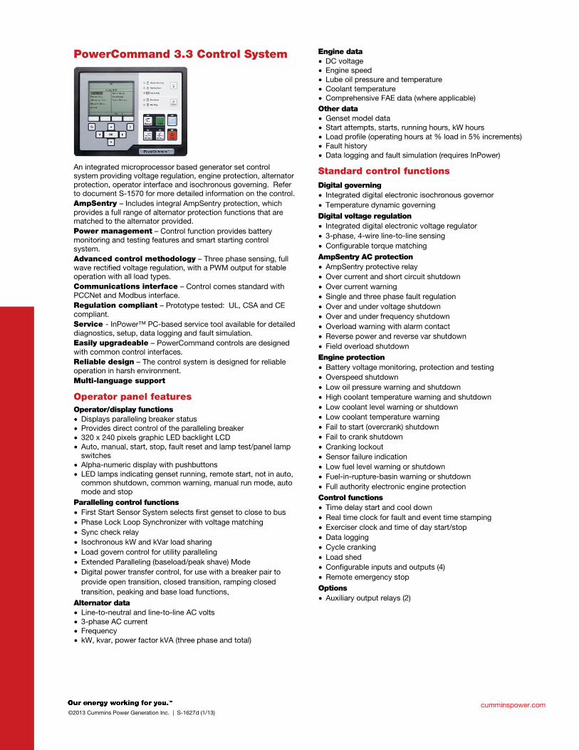
cumminspower.com ©2013 Cummins Power Generation Inc. | S-1627d (1/13)
PowerCommand 3.3 Control System
An integrated microprocessor based generator set control system providing voltage regulation, engine protection, alternator protection, operator interface and isochronous governing. Refer to document S-1570 for more detailed information on the control. AmpSentry – Includes integral AmpSentry protection, which provides a full range of alternator protection functions that are matched to the alternator provided. Power management – Control function provides battery monitoring and testing features and smart starting control system. Advanced control methodology – Three phase sensing, full wave rectified voltage regulation, with a PWM output for stable operation with all load types. Communications interface – Control comes standard with PCCNet and Modbus interface. Regulation compliant – Prototype tested: UL, CSA and CE compliant. Service - InPower™ PC-based service tool available for detailed diagnostics, setup, data logging and fault simulation. Easily upgradeable – PowerCommand controls are designed with common control interfaces. Reliable design – The control system is designed for reliable operation in harsh environment. Multi-language support
Operator panel features Operator/display functions • Displays paralleling breaker status • Provides direct control of the paralleling breaker • 320 x 240 pixels graphic LED backlight LCD • Auto, manual, start, stop, fault reset and lamp test/panel lamp
switches • Alpha-numeric display with pushbuttons • LED lamps indicating genset running, remote start, not in auto,
common shutdown, common warning, manual run mode, auto mode and stop
Paralleling control functions • First Start Sensor System selects first genset to close to bus • Phase Lock Loop Synchronizer with voltage matching • Sync check relay • Isochronous kW and kVar load sharing • Load govern control for utility paralleling • Extended Paralleling (baseload/peak shave) Mode • Digital power transfer control, for use with a breaker pair to
provide open transition, closed transition, ramping closed transition, peaking and base load functions,
Alternator data • Line-to-neutral and line-to-line AC volts • 3-phase AC current • Frequency • kW, kvar, power factor kVA (three phase and total)
Engine data • DC voltage • Engine speed • Lube oil pressure and temperature • Coolant temperature • Comprehensive FAE data (where applicable) Other data • Genset model data • Start attempts, starts, running hours, kW hours • Load profile (operating hours at % load in 5% increments) • Fault history • Data logging and fault simulation (requires InPower)
Standard control functions Digital governing • Integrated digital electronic isochronous governor • Temperature dynamic governing Digital voltage regulation • Integrated digital electronic voltage regulator • 3-phase, 4-wire line-to-line sensing • Configurable torque matching AmpSentry AC protection • AmpSentry protective relay • Over current and short circuit shutdown • Over current warning • Single and three phase fault regulation • Over and under voltage shutdown • Over and under frequency shutdown • Overload warning with alarm contact • Reverse power and reverse var shutdown • Field overload shutdown Engine protection • Battery voltage monitoring, protection and testing • Overspeed shutdown • Low oil pressure warning and shutdown • High coolant temperature warning and shutdown • Low coolant level warning or shutdown • Low coolant temperature warning • Fail to start (overcrank) shutdown • Fail to crank shutdown • Cranking lockout • Sensor failure indication • Low fuel level warning or shutdown • Fuel-in-rupture-basin warning or shutdown • Full authority electronic engine protection Control functions • Time delay start and cool down • Real time clock for fault and event time stamping • Exerciser clock and time of day start/stop • Data logging • Cycle cranking • Load shed • Configurable inputs and outputs (4) • Remote emergency stop Options • Auxiliary output relays (2)
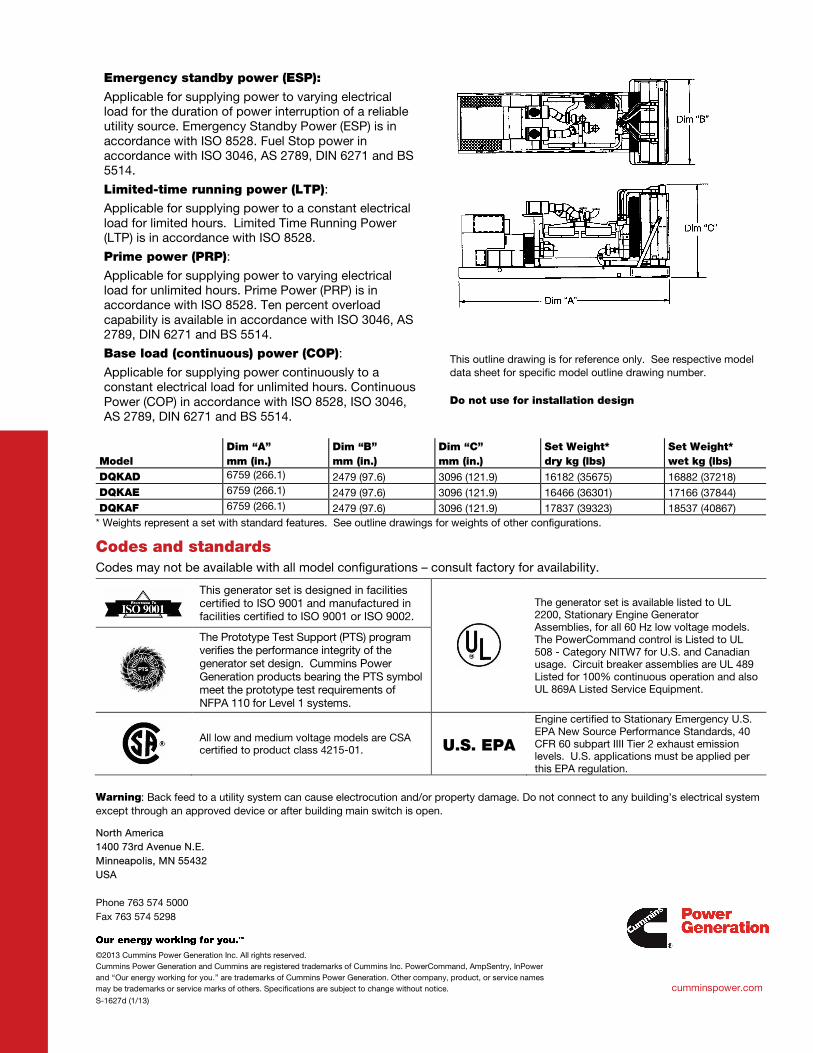
North America 1400 73rd Avenue N.E. Minneapolis, MN 55432 USA Phone 763 574 5000 Fax 763 574 5298
©2013 Cummins Power Generation Inc. All rights reserved. Cummins Power Generation and Cummins are registered trademarks of Cummins Inc. PowerCommand, AmpSentry, InPower and “Our energy working for you.” are trademarks of Cummins Power Generation. Other company, product, or service names may be trademarks or service marks of others. Specifications are subject to change without notice.
S-1627d (1/13)
cumminspower.com
Emergency standby power (ESP):
Applicable for supplying power to varying electrical load for the duration of power interruption of a reliable utility source. Emergency Standby Power (ESP) is in accordance with ISO 8528. Fuel Stop power in accordance with ISO 3046, AS 2789, DIN 6271 and BS 5514.
Limited-time running power (LTP):
Applicable for supplying power to a constant electrical load for limited hours. Limited Time Running Power (LTP) is in accordance with ISO 8528.
Prime power (PRP):
Applicable for supplying power to varying electrical load for unlimited hours. Prime Power (PRP) is in accordance with ISO 8528. Ten percent overload capability is available in accordance with ISO 3046, AS 2789, DIN 6271 and BS 5514.
Base load (continuous) power (COP):
Applicable for supplying power continuously to a constant electrical load for unlimited hours. Continuous Power (COP) in accordance with ISO 8528, ISO 3046, AS 2789, DIN 6271 and BS 5514.
This outline drawing is for reference only. See respective model data sheet for specific model outline drawing number. Do not use for installation design
Model Dim “A” mm (in.)
Dim “B” mm (in.)
Dim “C” mm (in.)
Set Weight* dry kg (lbs)
Set Weight* wet kg (lbs)
DQKAD 6759 (266.1) 2479 (97.6) 3096 (121.9) 16182 (35675) 16882 (37218) DQKAE 6759 (266.1) 2479 (97.6) 3096 (121.9) 16466 (36301) 17166 (37844) DQKAF 6759 (266.1) 2479 (97.6) 3096 (121.9) 17837 (39323) 18537 (40867)
* Weights represent a set with standard features. See outline drawings for weights of other configurations.
Codes and standards Codes may not be available with all model configurations – consult factory for availability.
This generator set is designed in facilities certified to ISO 9001 and manufactured in facilities certified to ISO 9001 or ISO 9002.
The generator set is available listed to UL 2200, Stationary Engine Generator Assemblies, for all 60 Hz low voltage models. The PowerCommand control is Listed to UL 508 - Category NITW7 for U.S. and Canadian usage. Circuit breaker assemblies are UL 489 Listed for 100% continuous operation and also UL 869A Listed Service Equipment.
The Prototype Test Support (PTS) program verifies the performance integrity of the generator set design. Cummins Power Generation products bearing the PTS symbol meet the prototype test requirements of NFPA 110 for Level 1 systems.
All low and medium voltage models are CSA certified to product class 4215-01. U.S. EPA
Engine certified to Stationary Emergency U.S. EPA New Source Performance Standards, 40 CFR 60 subpart IIII Tier 2 exhaust emission levels. U.S. applications must be applied per this EPA regulation.
Warning: Back feed to a utility system can cause electrocution and/or property damage. Do not connect to any building’s electrical system except through an approved device or after building main switch is open.
fc002
Rectangle
fc002
Line
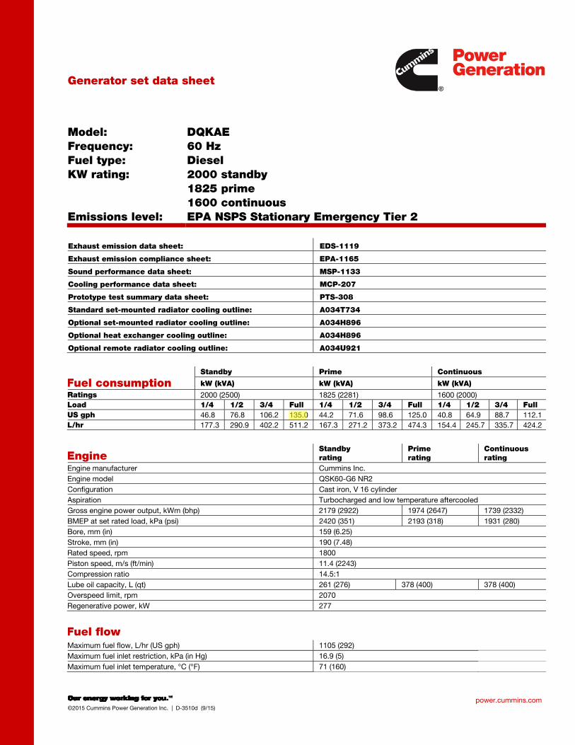
power.cummins.com ©2015 Cummins Power Generation Inc. | D-3510d (9/15)
Generator set data sheet
Model: Frequency: Fuel type: KW rating: Emissions level:
DQKAE 60 Hz Diesel 2000 standby 1825 prime 1600 continuous EPA NSPS Stationary Emergency Tier 2
Exhaust emission data sheet: EDS-1119
Exhaust emission compliance sheet: EPA-1165
Sound performance data sheet: MSP-1133
Cooling performance data sheet: MCP-207
Prototype test summary data sheet: PTS-308
Standard set-mounted radiator cooling outline: A034T734
Optional set-mounted radiator cooling outline: A034H896
Optional heat exchanger cooling outline: A034H896
Optional remote radiator cooling outline: A034U921
Fuel consumption Standby Prime Continuous
kW (kVA) kW (kVA) kW (kVA)
Ratings 2000 (2500) 1825 (2281) 1600 (2000)
Load 1/4 1/2 3/4 Full 1/4 1/2 3/4 Full 1/4 1/2 3/4 Full
US gph 46.8 76.8 106.2 135.0 44.2 71.6 98.6 125.0 40.8 64.9 88.7 112.1
L/hr 177.3 290.9 402.2 511.2 167.3 271.2 373.2 474.3 154.4 245.7 335.7 424.2
Engine Standby rating
Prime rating
Continuous rating
Engine manufacturer Cummins Inc.
Engine model QSK60-G6 NR2
Configuration Cast iron, V 16 cylinder
Aspiration Turbocharged and low temperature aftercooled
Gross engine power output, kWm (bhp) 2179 (2922) 1974 (2647) 1739 (2332)
BMEP at set rated load, kPa (psi) 2420 (351) 2193 (318) 1931 (280)
Bore, mm (in) 159 (6.25)
Stroke, mm (in) 190 (7.48)
Rated speed, rpm 1800
Piston speed, m/s (ft/min) 11.4 (2243)
Compression ratio 14.5:1
Lube oil capacity, L (qt) 261 (276) 378 (400) 378 (400)
Overspeed limit, rpm 2070
Regenerative power, kW 277
Fuel flow Maximum fuel flow, L/hr (US gph) 1105 (292)
Maximum fuel inlet restriction, kPa (in Hg) 16.9 (5)
Maximum fuel inlet temperature, °C (°F) 71 (160)
fc002
Rectangle
fc002
Line
fc002
Highlight
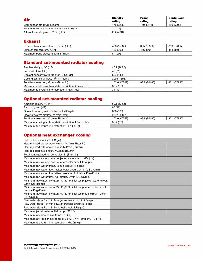
power.cummins.com ©2015 Cummins Power Generation Inc. | D-3510d (9/15)
Air Standby rating
Prime rating
Continuous rating
Combustion air, m3/min (scfm) 178 (6295) 159 (5615) 150 (5290)
Maximum air cleaner restriction, kPa (in H2O) 3.7 (15)
Alternator cooling air, m3/min (cfm) 222 (7840)
Exhaust
Exhaust flow at rated load, m3/min (cfm) 436 (15385) 385 (13580) 359 (12665)
Exhaust temperature, °C (°F) 482 (900) 466 (870) 454 (850)
Maximum back pressure, kPa (in H2O) 6.7 (27)
Standard set-mounted radiator cooling
Ambient design, °C ( °F) 40.7 (105.3)
Fan load, kWm (HP) 46 (61)
Coolant capacity (with radiator), L (US gal) 537 (142)
Cooling system air flow, m3/min (scfm) 2094 (73937)
Total heat rejection, MJ/min (Btu/min) 102.6 (97249) 88.8 (84180) 80.1 (75892)
Maximum cooling air flow static restriction, kPa (in H2O) 0.12 (0.5)
Maximum fuel return line restriction kPa (in Hg) 34 (10)
Optional set-mounted radiator cooling
Ambient design, °C (°F) 50.6 (123.1)
Fan load, kWm (HP) 66 (88)
Coolant capacity (with radiator), L (US gal) 606 (160)
Cooling system air flow, m3/min (scfm) 2347 (82891)
Total heat rejection, MJ/min (Btu/min) 102.6 (97249) 88.8 (84180) 80.1 (75892)
Maximum cooling air flow static restriction, kPa (in H2O) 0.12 (0.5)
Maximum fuel return line restriction, kPa (in Hg)
Optional heat exchanger cooling
Set coolant capacity, L (US gal)
Heat rejected, jacket water circuit, MJ/min (Btu/min)
Heat rejected, aftercooler circuit, MJ/min (Btu/min)
Heat rejected, fuel circuit, MJ/min (Btu/min)
Total heat radiated to room, MJ/min (Btu/min)
Maximum raw water pressure, jacket water circuit, kPa (psi)
Maximum raw water pressure, aftercooler circuit, kPa (psi)
Maximum raw water pressure, fuel circuit, kPa (psi)
Maximum raw water flow, jacket water circuit, L/min (US gal/min)
Maximum raw water flow, aftercooler circuit, L/min (US gal/min)
Maximum raw water flow, fuel circuit, L/min (US gal/min)
Minimum raw water flow at 27 °C (80 °F) inlet temp, jacket water circuit, L/min (US gal/min)
Minimum raw water flow at 27 °C (80 °F) inlet temp, aftercooler circuit, L/min (US gal/min)
Minimum raw water flow at 27 °C (80 °F) inlet temp, fuel circuit, L/min (US gal/min)
Raw water delta P at min flow, jacket water circuit, kPa (psi)
Raw water delta P at min flow, aftercooler circuit, kPa (psi)
Raw water delta P at min flow, fuel circuit, kPa (psi)
Maximum jacket water outlet temp, °C (°F)
Maximum aftercooler inlet temp, °C (°F)
Maximum aftercooler inlet temp at 25 °C (77 °F) ambient, °C ( °F)
Maximum fuel return line restriction, kPa (in Hg)
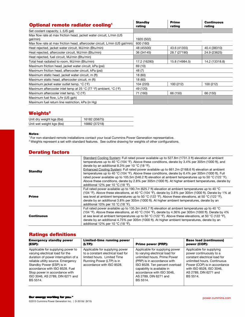
power.cummins.com ©2015 Cummins Power Generation Inc. | D-3510d (9/15)
Optional remote radiator cooling1 Standby rating
Prime rating
Continuous rating
Set coolant capacity, L (US gal) Max flow rate at max friction head, jacket water circuit, L/min (US gal/min) 1920 (502)
Max flow rate at max friction head, aftercooler circuit, L/min (US gal/min) 600 (160)
Heat rejected, jacket water circuit, MJ/min (Btu/min) 48 (45500) 43.6 (41355) 40.4 (38310)
Heat rejected, aftercooler circuit, MJ/min (Btu/min) 36 (34145) 28.7 (27190) 24.9 (23625)
Heat rejected, fuel circuit, MJ/min (Btu/min)
Total heat radiated to room, MJ/min (Btu/min) 17.2 (16280) 15.8 (14984.5) 14.2 (13318.8)
Maximum friction head, jacket water circuit, kPa (psi) 69 (10)
Maximum friction head, aftercooler circuit, kPa (psi) 48 (7)
Maximum static head, jacket water circuit, m (ft) 18 (60)
Maximum static head, aftercooler circuit, m (ft) 18 (60)
Maximum jacket water outlet temp, C (F) 104 (220) 100 (212) 100 (212)
Maximum aftercooler inlet temp at 25 C (77 F) ambient, C (F) 49 (120)
Maximum aftercooler inlet temp, C (F) 71 (160) 66 (150) 66 (150)
Maximum fuel flow, L/hr (US gph)
Maximum fuel return line restriction, kPa (in Hg)
Weights2
Unit dry weight kgs (lbs) 16182 (35675)
Unit wet weight kgs (lbs) 16882 (37218)
Notes: 1 For non-standard remote installations contact your local Cummins Power Generation representative. 2 Weights represent a set with standard features. See outline drawing for weights of other configurations.
Derating factors
Standby
Standard Cooling System: Full rated power available up to 527.8m (1731.3 ft) elevation at ambient temperatures up to 40 °C (104 °F). Above these conditions, derate by 3.4% per 305m (1000 ft), and derate by an additional 8.3% per 10 °C (18 °F). Enhanced Cooling System: Full rated power available up to 661.2m (2168.6 ft) elevation at ambient temperatures up to 40 °C (104 °F). Above these conditions, derate by 6.4% per 305m (1000 ft). Full rated power available up to 105.5m (346.2 ft) elevation at ambient temperatures up to 50 °C (122 °F). Above these conditions, derate by 2.8% per 305m (1000 ft). At higher ambient temperatures, derate by additional 12% per 10 °C (18 °F).
Prime
Full rated power available up to 190.7m (625.7 ft) elevation at ambient temperatures up to 40 °C (104 °F). Above these elevations, at 40 °C (104 °F), derate by 3.8% per 305m (1000 ft). Derate by 1% at sea level at ambient temperatures up to 50 °C (122 °F). Above these elevations, at 50 °C (122 °F), derate by an additional 3.8% per 305m (1000 ft). At higher ambient temperatures, derate by an additional 10% per 10 °C (18 °F).
Continuous
Full rated power available up to 135.3m (443.7 ft) elevation at ambient temperatures up to 40 °C (104 °F). Above these elevations, at 40 °C (104 °F), derate by 4.36% per 305m (1000 ft). Derate by 4% at sea level at ambient temperatures up to 50 °C (122 °F). Above these elevations, at 50 °C (122 °F), derate by an additional 4.75% per 305m (1000 ft). At higher ambient temperatures, derate by an additional 12% per 10 °C (18 °F).
Ratings definitions
Emergency standby power (ESP):
Limited-time running power (LTP): Prime power (PRP):
Base load (continuous) power (COP):
Applicable for supplying power to varying electrical load for the duration of power interruption of a reliable utility source. Emergency Standby Power (ESP) is in accordance with ISO 8528. Fuel Stop power in accordance with ISO 3046, AS 2789, DIN 6271 and BS 5514.
Applicable for supplying power to a constant electrical load for limited hours. Limited Time Running Power (LTP) is in accordance with ISO 8528.
Applicable for supplying power to varying electrical load for unlimited hours. Prime Power (PRP) is in accordance with ISO 8528. Ten percent overload capability is available in accordance with ISO 3046, AS 2789, DIN 6271 and BS 5514.
Applicable for supplying power continuously to a constant electrical load for unlimited hours. Continuous Power (COP) is in accordance with ISO 8528, ISO 3046, AS 2789, DIN 6271 and BS 5514.
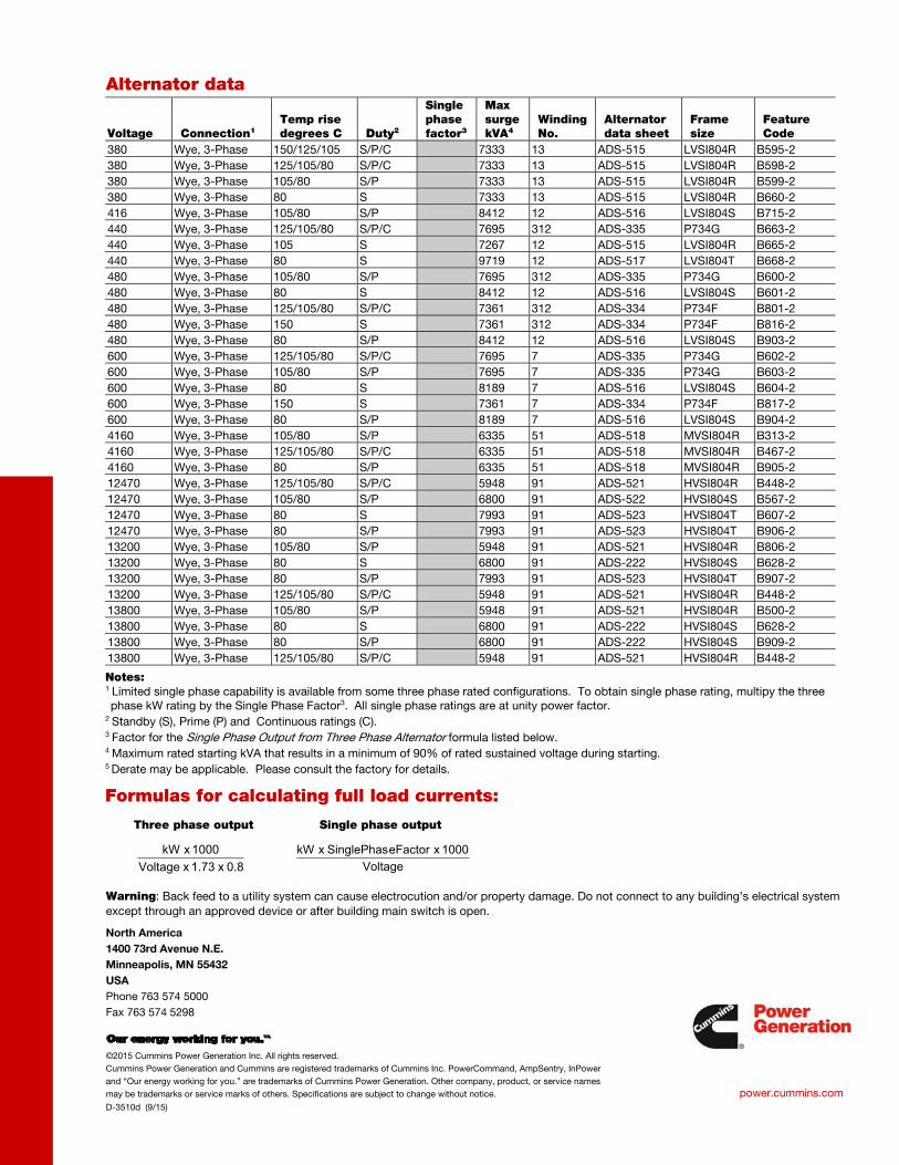
North America
1400 73rd Avenue N.E.
Minneapolis, MN 55432
USA
Phone 763 574 5000
Fax 763 574 5298
©2015 Cummins Power Generation Inc. All rights reserved.
Cummins Power Generation and Cummins are registered trademarks of Cummins Inc. PowerCommand, AmpSentry, InPower
and “Our energy working for you.” are trademarks of Cummins Power Generation. Other company, product, or service names
may be trademarks or service marks of others. Specifications are subject to change without notice.
D-3510d (9/15)
power.cummins.com
Alternator data
Voltage Connection1 Temp rise degrees C Duty2
Single phase factor3
Max surge kVA4
Winding No.
Alternator data sheet
Frame size
Feature Code
380 Wye, 3-Phase 150/125/105 S/P/C 7333 13 ADS-515 LVSI804R B595-2
380 Wye, 3-Phase 125/105/80 S/P/C 7333 13 ADS-515 LVSI804R B598-2
380 Wye, 3-Phase 105/80 S/P 7333 13 ADS-515 LVSI804R B599-2
380 Wye, 3-Phase 80 S 7333 13 ADS-515 LVSI804R B660-2
416 Wye, 3-Phase 105/80 S/P 8412 12 ADS-516 LVSI804S B715-2
440 Wye, 3-Phase 125/105/80 S/P/C 7695 312 ADS-335 P734G B663-2
440 Wye, 3-Phase 105 S 7267 12 ADS-515 LVSI804R B665-2
440 Wye, 3-Phase 80 S 9719 12 ADS-517 LVSI804T B668-2
480 Wye, 3-Phase 105/80 S/P 7695 312 ADS-335 P734G B600-2
480 Wye, 3-Phase 80 S 8412 12 ADS-516 LVSI804S B601-2
480 Wye, 3-Phase 125/105/80 S/P/C 7361 312 ADS-334 P734F B801-2
480 Wye, 3-Phase 150 S 7361 312 ADS-334 P734F B816-2
480 Wye, 3-Phase 80 S/P 8412 12 ADS-516 LVSI804S B903-2
600 Wye, 3-Phase 125/105/80 S/P/C 7695 7 ADS-335 P734G B602-2
600 Wye, 3-Phase 105/80 S/P 7695 7 ADS-335 P734G B603-2
600 Wye, 3-Phase 80 S 8189 7 ADS-516 LVSI804S B604-2
600 Wye, 3-Phase 150 S 7361 7 ADS-334 P734F B817-2
600 Wye, 3-Phase 80 S/P 8189 7 ADS-516 LVSI804S B904-2
4160 Wye, 3-Phase 105/80 S/P 6335 51 ADS-518 MVSI804R B313-2
4160 Wye, 3-Phase 125/105/80 S/P/C 6335 51 ADS-518 MVSI804R B467-2
4160 Wye, 3-Phase 80 S/P 6335 51 ADS-518 MVSI804R B905-2
12470 Wye, 3-Phase 125/105/80 S/P/C 5948 91 ADS-521 HVSI804R B448-2
12470 Wye, 3-Phase 105/80 S/P 6800 91 ADS-522 HVSI804S B567-2
12470 Wye, 3-Phase 80 S 7993 91 ADS-523 HVSI804T B607-2
12470 Wye, 3-Phase 80 S/P 7993 91 ADS-523 HVSI804T B906-2
13200 Wye, 3-Phase 105/80 S/P 5948 91 ADS-521 HVSI804R B806-2
13200 Wye, 3-Phase 80 S 6800 91 ADS-222 HVSI804S B628-2
13200 Wye, 3-Phase 80 S/P 7993 91 ADS-523 HVSI804T B907-2
13200 Wye, 3-Phase 125/105/80 S/P/C 5948 91 ADS-521 HVSI804R B448-2
13800 Wye, 3-Phase 105/80 S/P 5948 91 ADS-521 HVSI804R B500-2
13800 Wye, 3-Phase 80 S 6800 91 ADS-222 HVSI804S B628-2
13800 Wye, 3-Phase 80 S/P 6800 91 ADS-222 HVSI804S B909-2
13800 Wye, 3-Phase 125/105/80 S/P/C 5948 91 ADS-521 HVSI804R B448-2
Notes: 1 Limited single phase capability is available from some three phase rated configurations. To obtain single phase rating, multipy the three phase kW rating by the Single Phase Factor3. All single phase ratings are at unity power factor.
2 Standby (S), Prime (P) and Continuous ratings (C). 3 Factor for the Single Phase Output from Three Phase Alternator formula listed below. 4 Maximum rated starting kVA that results in a minimum of 90% of rated sustained voltage during starting. 5 Derate may be applicable. Please consult the factory for details.
Formulas for calculating full load currents:
Three phase output Single phase output
Warning: Back feed to a utility system can cause electrocution and/or property damage. Do not connect to any building’s electrical system
except through an approved device or after building main switch is open.
Voltage
1000 x eFactorSinglePhas x kW
0.8 x 1.73 x Voltage
1000 x kW
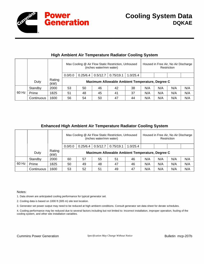
Cooling System Data DQKAE
High Ambient Air Temperature Radiator Cooling System
Max Cooling @ Air Flow Static Restriction, Unhoused (inches water/mm water)
Housed in Free Air, No Air Discharge Restriction
0.0/0.0 0.25/6.4 0.5/12.7 0.75/19.1 1.0/25.4 Duty Rating
(kW) Maximum Allowable Ambient Temperature, Degree C Standby 2000 53 50 46 42 38 N/A N/A N/A N/A 60 Hz Prime 1825 51 48 45 41 37 N/A N/A N/A N/A Continuous 1600 56 54 50 47 44 N/A N/A N/A N/A
Enhanced High Ambient Air Temperature Radiator Cooling System
Max Cooling @ Air Flow Static Restriction, Unhoused (inches water/mm water)
Housed in Free Air, No Air Discharge Restriction
0.0/0.0 0.25/6.4 0.5/12.7 0.75/19.1 1.0/25.4 Duty Rating
(kW) Maximum Allowable Ambient Temperature, Degree C Standby 2000 60 57 55 51 46 N/A N/A N/A N/A 60 Hz Prime 1825 50 49 48 47 46 N/A N/A N/A N/A Continuous 1600 53 52 51 49 47 N/A N/A N/A N/A Notes: 1. Data shown are anticipated cooling performance for typical generator set.
2. Cooling data is based on 1000 ft (305 m) site test location.
3. Generator set power output may need to be reduced at high ambient conditions. Consult generator set data sheet for derate schedules.
4. Cooling performance may be reduced due to several factors including but not limited to: Incorrect installation, improper operation, fouling of the cooling system, and other site installation variables.
Cummins Power Generation Specification May Change Without Notice Bulletin mcp-207b
fc002
Rectangle
fc002
Rectangle
Related Documents