SUMMARY BOYER COMPANY figures, activities, cutomers and positioning machining of exotic materials microdrilling and ultraprecision measurement services HIGH GRADIENT RF COMPONENTS past and present activities results on the test part technical developments (control and machining) comments machining of a complete structure

SUMMARY BOYER COMPANY figures, activities, cutomers and positioning machining of exotic materials microdrilling and ultraprecision measurement services.
Dec 22, 2015
Welcome message from author
This document is posted to help you gain knowledge. Please leave a comment to let me know what you think about it! Share it to your friends and learn new things together.
Transcript

SUMMARY
BOYER COMPANY figures, activities, cutomers and positioning machining of exotic materials microdrilling and ultraprecision measurement services
HIGH GRADIENT RF COMPONENTS past and present activities results on the test part technical developments (control and machining) comments machining of a complete structure

BOYER COMPANYSOME FIGURES30 years of existence47 people2800 M25 Meuros of turnover
ACTIVITIES AND CUSTOMERSNuclear weapons(CEA/DAM)Civilian nuclear(AREVA NP services nucléaires, CERN)Defense (THALES UNDERWATER SYSTEMS)Energy (S2M)Aeronautics and space sector (SNECMA)Optical sector (ESSILOR)Automotive (HONEYWELL, DELPHI)
POSITIONINGPrecision machining and ultraprecision from prototype to medium production runs.Manufacturing, assembly and measurement services

Machining of exotic materials
EXPERIENCE
An important know-how acquired in the field of Civilian and Military nuclear sector as well as in research
An established team accustomed to machining new materials
Materials: tantalum, titanium, copper, molybdenum, vespel, aluminum, graphite, steel, Inconel, Maraging, AlSi MMC etc ...

Microdrilling
Microdrilling of cylindrical holes from diam. 0.1 mm to 0.25 mm in a gold plate 0.05 mm thick.Required tolerances for diameters, spacings and positions: 0.01 mm.Result: less than 0.005 mm. Without deformation at the entry
Machining of a grid composed of square holes of 0.10 mm x 0.10 mm ± 0.02 Result: 0.01 mm in size and radius angle 0.01 to 0.015 mmMicromachining was carried out without deformation or alteration of the material.
Holes compared with a pen tip
The required accuracy is guaranteed by our means of measurement of three-dimensional machine WERTH

ULTRA PRECISION machiningNANOFORM 250 ULTRAGRIND
diamond turning and milling of ultra precision
Three axes (X, Z, C) X and Z: 220 mmPosition 0.2 m,Ra <10 nm,Tolerance of form <0.5 microns
Gobal deformity of 5 µmRa 50 nm
Milling in H of a tin part
Micro drilling of a pure aluminum part

MEASURING SERVICESequipment
1 optical measurement WERTH device750x405x410mm 4th axis 3D measurement by laser optical system and high precision controls fragile parts, deformable or too small and can not be by conventional means.
1 ZEISS Prismo 7 (integrated rotary 4th axis, measuring head)1500 x 900 x 700 mm1 ZEISS Prismo 5 Super ACC (added rotary 4th axis, measuring head)700 * 900 * 500 mm1 ZEISS UMM 850 (integrated rotary 4th axis, measuring head)850 * 1200 * 600 mm 1 Machine ZEISS MC 850 (added rotary 4th axis )850 * 1200 * 600 mm
1 FORM TALYSURF Série 2 Taylor Hobson

- Three-dimensional control of the first part (development of the range of control, the control program and analysis of results) - Provision of control programs and start on site - Load shedding control 3D standard parts - Dimensional inspection and sampling of three-dimensional qualityAnalysis of the results includes a chart, listing machine with gaps identified and popularized a summary containing the information from the protocol defined with the customer.
MEASURING SERVICES
Screen copy of a part machined on EDM SARIX machine
Drawing of a blade section

ACTIVITIES ON HIGH GRADIENT RF COMPONENTS
PAST ACTIVITIES machining of a test part delivered in june 2011
CURRENT ACTVITIES machining of a complete structure

Y+
AG
Section 10
Z+
X+
Résultats de contrôle : Rapport de contrôle remplie et tracés de profils et rugosité.
C LIA AS 110337_N 13_B.X LS
±
ANNEXE 1
0.005 A B
Page 1/1
C E R N
RC 11-0602
Cde : CA 1506078
et 0.025
Numéro pièce : CLIAAS110337 / 13 Matière : Cu-OFE
Nom pièce : STANDARD CELL N° Plan : CLIAAS110337
Y Section 2
X
D IM E N S IO N N E L
Z+
Ra Zone 3
X+
AB
Ra Zone 4 AM
Z Section 3
AC Section 6
X+
Y+
Ra Zone 1 Z+
AA Section 4
AF Section 9
Z+
X+
Y+
Ra Zone 2 AK
AE
Section 8
Ra ellipse
AN
AH Section 11
Y+
Y+
Z+
X+
Section 5
AJ
AD Section 7
CLIAAS110337_N 13_B.XLS
AL

J
D
vo ir an n exe 1
A I et vo ir an n exe 1
AP
T
vo ir an n exe 1
A O R 0.05
Page 1 / 2
C E R N
RC 11-0602
Cde : CA 1506078
Numéro pièce : CLIAAS110337 / 13 Matière : C u -O F E
Nom pièce : STANDARD CELL N° Plan : C L IA A S 1 1 0 3 37 D IM E N S IO N N E L
I
F
V a leu r V a leu r V a leu r
R ep in fér ieu r e m esu ré e su p é r ieu r e B
H o r s
T o l.
0 .0 0 7
0 .0 2 5
A
E K
H
A
B
C
D
E
0 .0 00 0
0 .0 00 0
7 3 .99 7 5
7 0 .01 0 0
0 .0 00 0
0 .0 00 0
0 .0 00 0
0 .0 00 0
0 .0 00 0
0 .0 01 0
0 .0 02 0
7 4 ..0 0 2 5
7 0 .01 5 0
0 .0 05 0
0 .0 01 0
0 .0 02 0
0 .0 01 0
0 .0 02 0
7 0 .00 0 0
0 .0 05 0
1 .6 00 0
2 .5 50 0
0 .6 50
0 .6 00
M A U V A IS
0 .5 00
4 .1 00
0 .0 10
M A U V A IS
2 7 .02 0
2 .4 25
M A U V A IS
0 .0 05 0
0 .0 05 0
0 .0 05 0
0 .0 05 0
0 .0 05 0
0 .0 05 0
0 .0 05 0
0 .0 05 0
0 .0 05 0
0 .0 05 0
0 .0 05 0
0.025 maxi
0.025 maxi
0.025 maxi
0.025 maxi
0.025 maxi
0.025 maxi
M A U V A IS
M A U V A IS
0 .0 00 7
0 .0 01 9
7 3 .99 8 9
7 0 .011 5
0 .0 02 0
0 .0 01 4
0 .0 01 5
0 .0 00 9
0 .0 01 2
6 9 .99 4 1
0 .0 00 3
1 .4 99 8
2 .5 03 1
0 .6 26
0 .4 92
B O N
0 .4 77
4 .0 74
0 .0 17
B O N
2 6 .98 5
2 .4 18
B O N
0 .0 02 6
0 .0 04 4
0 .0 01 4
0 .0 02 8
0 .0 04 8
0 .0 05 0
0 .0 01 2
0 .0 01 6
0 .0 02 8
0 .0 02 6
0 .0 01 8
0 .0 07
0 .0 08
0 .0 08
0 .0 18
0 .0 10
0 .0 50
B O N
20° C
20° C
G F
G
H
I
J 6 9 .99 0 0
K 0 .0 0 0 0
L 1 .4 0 0 0
M 2 .4 50 0
N 0 .6 0 0
O 0 .4 0 0
P B O N
Q 0 .4 5 0
R 4 .00 0
S 0 .0 00
T B O N
U 2 6 .9 2 0
V 2 .37 5
W B O N
C
W
W
W
V
R
U S
Q
P
L
X
Y
Z
A A
AB
A C
A D
A E
AF
A G
A H
0 .0 00 0
0 .0 00 0
0 .0 00 0
0 .0 00 0
0 .0 00 0
0 .0 00 0
0 .0 00 0
0 .0 0 0 0
0 .0 00 0
0 .0 00 0
0 .0 00 0
/
/
/
/
/
/
B O N
B O N
N A I
A J
A K
AL
A M
A N
A O
AP
O
M
A Q T° pièce
AR T° local
FOURNISSEUR : Ets YVON BOYER
Observations : Nota 1 : la cote repère S est hors tolérance, pour information la cote se situe à l'entrée d'un des 4 trous Ø4.
Nota 2 : suite a vos remarques nous avons effectué une mesure de rugosité dans la zone elliptique cote repère AN qui s'avère être hors tolérance. Cette valeur est simplement due au pas d'usinage, par conséquent en réduisant le pas par 2 ou 3 la rugosité serait conforme. Pour information l'outil utilisé dans cette zone est identique a celui des zones 1 et 2 ou nous obtenons une rugosité de 0.007 à 0.008.
C LIA AS 110337_N 13_B .X LS
ORGANISME CONTROLE
Ets YVON BOYER
Date : 08 juin 2011
Lieu : St Hilaire les Andrésis
Contrôleur : STP
Vérificateur : S T P

N°3 Calypso Caractéristique :
Défauts de forme section 1
10.0µm
N om ina l Ecart To l. Sup. To l. Inf.
3
P oints arête 1
2
3
4
X Y Z
1,4012
1,4012
1,4009
1,4010
1,4025
1,4010
-27,0021 27,0016
26,9987 27,0016
26,9987 -26,9991
-27,0021 -26,9991
12,9986 - 1,6525
1,6517 -26,9990
1.0µm M a x
Min
0,0006
- 0,0008
A m plification 10000
Nr Repére VM E To lé rance Pts V itesse R ayon P alp Type f. L C O /T
1 IS O P lanéité face à t 0,0014 0,0010 44 0,7497
Désignation pièce: Client:
STAN D AR D C ELL C ER N
No plan: Numéro de pièce:
C LIAAS110337_N 13
Opérateur : Date : 7 Juin 2011
Z [m m ]
30 .0
20 .0
10 .0
0.0
-10.0
-20.0
-30.0
Nom Plan de contrôle :
STP CERN_A
-30 .0 -20.0 -10 .0 0.0 10 .0 20 .0 Y [m m ]
Translation Rotation Amplification 1000 Résultat de balancement X 0.0000
Y -0.0012
0.0000
0.0000 0.0000
Commentaire 0.0001 Z
Sigm a Form Pts Tol. Inf. Tol. S up. M inInd écart M in. M axInd écart M ax.
0,0006 0 ,00 22 244 -0,0025 0 ,002 5 207 -0,0009 43 0,0013

X


TECHNICAL DEVELOPMENTS
CONTROL - fitting tool to maintain the part without deforming it - minimum of contact to avoid to mark the part - use of the super ACC ZEISS machine to get the precision
MACHINING - fitting tool to get the 1µm flatness - setting of the tool (diameter, radius, position in X and Y) - milling strategy to get the best roughness possible - feedrate, cutting speed - good speed to obtain the good following of the axis

COMMENTS
We know now that it is feasable in the precision asked but it has required : - a lot of developments to get the precision and the roughness required - a lot of time to machine the standard part
Any change in the design implies changes in the process and development of the manufacturing

MACHINING OF A COMPLETE STRUCTURE
PROBLEMATIC - the aim is to manage to produce parts according to the drawings in a limited time - It implies to have a reliable processDIFFICULTIES - It is necessary to reduce the number of operations at the minimum - It will be necessary to monitor the tool wear for a complete structure - The design of the milling has changed. The radius at the bottom decreased from 3,15 mm to 0,5 mm, thus the type of milling tool is different.The milling strategy has to be reviewed to get the good roughness Example : the path of milling to mill the cross should be divided by 2,5 to get the same roughness
STATE OF PROGRESS
- The milling operation is validated in term of roughness- The turning operations are validated- The flatness in milling and turning is validated
-We are in a process of validation of the exact position of the milling tool (X, Y) This is the last point to be able to launch the machining of a complete part.
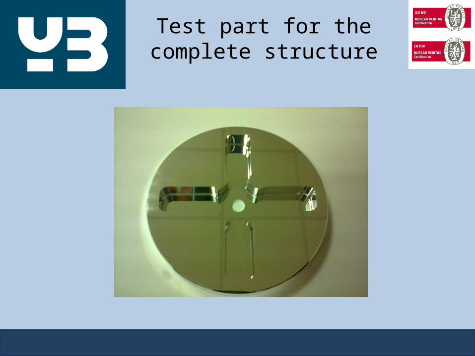
Test part for the complete structure
Related Documents


