/ 1 Sulzer Pumps

Sulzer Pumps - Home - Calgary Pump · PDF fileSulzer Pumps UK Ltd. [email protected] / 3 ... design or operation of Centrifugal Pumps who wants to ... areas of pump design
Feb 02, 2018
Welcome message from author
This document is posted to help you gain knowledge. Please leave a comment to let me know what you think about it! Share it to your friends and learn new things together.
Transcript

/ 1
Sulzer Pumps

/ 2
Practical Lateral Rotordynamics forCentrifugal Pumps
Pump SymposiumCalgary November 2007
Brian GermaineSulzer Pumps UK Ltd.

/ 3
Practical Rotordynamics for Centrifugal Pumps
This workshop will present a practical view of Lateral Rotordynamics for Centrifugal Pumps. The procedures for undertaking such investigations will be explained along with the important rotordynamic features that exist within multistage pumps.
API 610 Appendix I will be presented and compared to procedures adopted for centrifugal compressors. "Stiff-shaft" and "flexible-shaft" systems will be discussed along with practical examples.
This workshop will be of benefit for any Engineer involved in the specification, design or operation of Centrifugal Pumps who wants to gain a good understanding of rotordynamics and many of the myths that surround this subject.

/ 4
Practical Rotordynamics for Centrifugal Pumps
Agenda
Introduction to the World of Rotordynamics
API 610 Requirements: "Old" & "New"
Definition of "Stiff Shaft" and "Flexible Shaft"
The Process – Damped Lateral Calculations
Rotordynamic Development & Testing
Instability & Unbalance Response
Swirl Brake Design & Rotor Damping
Practical Examples & Parameter Changes

/ 5
Introduction

/ 6
Practical Rotordynamics for Centrifugal Pumps
"Rotordynamics is the science of predicting the vibrational
behaviour of rotors of any kind"
Rankine 1869 was the first person to perform ananalysis of a spinning shaft

/ 7
Practical Rotordynamics for Centrifugal Pumps
cm
k
x
F(t)
m)xx(k static+ xc&
)t(F mg
Single Degree of Freedom System
kxxc)t(Fxm −−= &&&
Equation of motion about the static equilibrium position does not contain weight and weight balancing force. Force is assumed to be linear to their driving parameters
Unforced System
Second-order homogenous ordinary differential equation
Eigenvalue problem (damping neglected)
Imaginary part of complex solution is the undamped natural frequency or Eigenfrequency
0=++ kxxcxm &&&
02 =++ kcm λλ
mkj
mk
±=−±= 02,1λ
mk
=Ω0

/ 8
Practical Rotordynamics for Centrifugal Pumps
Laval (Jeffcott) Rotor
m)ee(k static+
2Ωme mg
e
Mass-less shaft with bearing stiffness (k)Disc-like mass (m) at mid-span, supported on rigid bearings, perfectly balancedUnforced & un-damped system with circular orbit
Dynamic equilibrium i.e. centrifugal force = shaft force
Ω is called the critical speed and in this case is also the natural frequency
ω=Ω
02 =−Ω keme
0)( 2 =−Ωmkme
02 =−Ωmk

/ 9
Practical Rotordynamics for Centrifugal PumpsJournal Bearings
ω⋅η⋅⋅ψ⋅
=DB
FSo2
StaticSommerfeld Number,
2
StaticFnDBS
ψ⋅⋅η⋅⋅
=Sommerfeld Number US,
Cylindrical bearings have good static properties. Where dynamic behaviour is critical, lobed or tilting pad bearings are better

/ 10
Practical Rotordynamics for Centrifugal Pumps
OutletInlet
p
Fy
resulting force proportional to area
Annular Seals The main difference between bearing and annular seal is the axial pressure differential axial flowAxial flow in pump annular seals is normally turbulent.
"Lomakin" effect: Bearing capability due to axial through flow, without any contribution from rotor or fluid rotation, leads to restoring radial forces if the rotor is laterally displaced.
Stiffness (k) is proportional to the pressure differential
Stiffness (k) decreases with increasing clearance h0

/ 11
Practical Rotordynamics for Centrifugal Pumps
Annular Seals Circulatory De-stabilizing Force:The rotor as well as the fluid flowing through the annular seal are rotating i.e. have circumferential velocity. Distortion of the pressure profile due to this rotation yields forces perpendicular to the displacement.These forces are non-conservative
Fluid rotation in annular seals has two origins: 1) fluid pre-rotation at entrance u1 and 2) shear forces at the surface of the rotating part.
For short seals with L/D << 1, the destabilizing force is proportional to u1and is expressed by the cross-coupled stiffness
asymmetric pressureprofile due to rotation

/ 12
Practical Rotordynamics for Centrifugal Pumps
Annular Seals Coefficients
/ 13
Practical Rotordynamics for Centrifugal Pumps
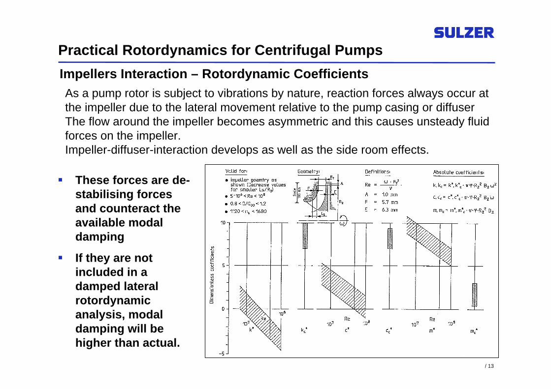
As a pump rotor is subject to vibrations by nature, reaction forces always occur at the impeller due to the lateral movement relative to the pump casing or diffuser The flow around the impeller becomes asymmetric and this causes unsteady fluid forces on the impeller. Impeller-diffuser-interaction develops as well as the side room effects.
Impellers Interaction – Rotordynamic Coefficients
These forces are de-stabilising forces and counteract the available modal damping
If they are not included in a damped lateral rotordynamic analysis, modal damping will be higher than actual.

/ 14
Practical Rotordynamics for Centrifugal Pumps
Investigation of dynamic system behaviorFor pump rotors, Eigenfrequencies are a function of shaft speedCritical speeds are the intersection points of natural frequency curves with 1x n lineNatural frequencies depend on shaft speed, critical speeds do notDamping is "modal" damping
Campbell & Damping Diagrams

/ 15
API 610 10th Edition Appendix ISpecification for Performing Lateral
Rotordynamics for Pumps

/ 16
Practical Rotordynamics for Centrifugal PumpsAnalysis of 1st, 2nd and 3rd dry critical speedsClassically stiff first dry critical speed > 1.2x max. continuous shaft speed if wet running onlyAnalysis for new and worn (2x new) clearance conditionsAnalysis at expected temperature for water (new) and pumped liquid (new and worn)Analysis for operational speed range from 25% to 125% of rated shaft speedIncludes stiffness and damping at labyrinth type shaft seals, including bearingsConsiders stiffness of bearing support structureFor both new and worn clearances the damping factor vs. separation margin to be calculated
1) Acceptable Region
2) Improvement Desired

/ 17
API 610 7th Edition Appendix IA Specification for Compressors

/ 18
Practical Rotordynamics for Centrifugal Pumps
API 610 7th Edition; defined the analysis process completely differentlyAnalysis focused on unbalance response analysis onlyPosition of critical speed and damping level importantProcedure identical to API 617 – Turbo CompressorsDamping calculated from curve shape at first critical speed positionProcedure not sensible for centrifugal pumpsAmplification factor defines damping level, log decrement etc.

/ 19
Definition of "Stiff" vs. "Flexible" Rotors

/ 20
Practical Rotordynamics for Centrifugal Pumps
ISO 13709 (API 610) requires all 1 and 2 stage (OH, BB1 and BB2) pumps to have their first critical speed in air to be at least 20% above operating speed.
"Stiff Shaft" or "Large Shaft" machines have lower static deflection under no rotation than the radial clearance (statically stiff)
Duncan & Hood 1976, define "stiff shaft" pumps when the first Eigenfrequency in air is higher than the running frequency i.e. fe/fn > 1 (dynamically stiff)
Definition of "Stiff Shaft" Design

/ 21
Practical Rotordynamics for Centrifugal Pumps
"Flexible" or "slender" rotors have their first lateral critical speed in air, below the operating speed."Flexible" rotors typically will have contact between stationaryand rotating wear parts at start-up and shut-down.During operating the center and throttle bushings act as productlubricated bearings and add significant stiffening and damping – making for a very "stiff" rotor in operation.
Definition of "Flexible" Design

/ 22
Practical Rotordynamics for Centrifugal Pumps
Often the feeling is "The thicker the shaft the better" and pumps are praised (or cursed) based on the shaft thickness.
Concerning hydraulic behaviour, it is undisputed that thinner shafts tend to increase efficiency, head coefficient and improve suction performance.
In general, multistage centrifugal pumps are dynamically flexible.
Duncan & Hood Guidance Chart

/ 23
The Process – Damped Lateral Rotordynamic Calculations

/ 24
Practical Rotordynamics for Centrifugal Pumps
SULZER LATERAL-PU
Finite Element Core: MADYN
Pre-processor:Rotor geometryPump data: Bearings
LubricantSealsImpellersOperating data
BITER • Shaft Deflec. • Bearing load
PROGRAMS „SEAL“
„HSEALM“
DATA BASE
ROTOR GEOMETRY
PUMP DATA
• Bearings • Seals • Impellers • Oper. Data
• Seal Coeff. • Bearing
Coefficient • Impeller
Interaction
• Static Beahaviour • Eigenvalues • Forced Response
Damped Eigenvalues
Forced Response
Static Deflection and Stresses
Campbell Plot Runup
Stress Evaluation
• Yielding • Fatigue
Forces
A
n
ϕ
A, ϕ
MADYN
n
f
2
1
D2
D1
D=0
FAx
T
Mb
ms ms
Bearing
Bearing housing Support
kB cB
kS cS
kB cB
kS cS

/ 25
Practical Rotordynamics for Centrifugal Pumps
Standstill
Running
Radial clearances
Journal bearing
Journal bearing
at Standstill
Running
ee = Offset
Rotor Setting

/ 26
Practical Rotordynamics for Centrifugal Pumps
LATERAL DAMPED NATURAL FREQUENCIES ANALYSIS DATE: 12.Apr.2003LATERAL Rev. 4.5A
HPcp 350-425-8s/27m,NEWSulzer Pumps UK Ltd
Analysis.... 304122026, HPcp 350-425-8s/27m,NEWPump State: NewMode Shape No. 1
orbit with max. major axis, t = 0, t = /2
Y
X
Z
Speed = 1200 rpmF= 35.02 HzD= 26.9 %
Speed = 2400 rpmF= 57.21 HzD= 28.2 %
Speed = 3600 rpmF= 80.42 HzD= 25.6 %
Speed = 4800 rpmF= 105.53 HzD= 23.1 %
Speed = 6000 rpmF= 125.53 HzD= 20.4 %
EIGVC: CAMPBELL AND DAMPING DIAGRAM DATE: 12.Apr.2003LATERAL Rev. 4.5A
HPcp 350-425-8s/27m,NEWSulzer Pumps UK Ltd
Analysis.... 304122026, HPcp 350-425-8s/27m,NEWPump State: New
Mode 2: Mode 1:List of Symbols:
1200 2160 3120 4080 5040 6000Rotor Speed [rpm]
030
60
90
120
150
Frequency [Hz]
Synchronous Excitation
nn
nmin
nmax
1200 2160 3120 4080 5040 6000Rotor Speed [rpm]
010
20
30
40
50
Damping [%]

/ 27
RotordynamicDevelopment & Testing

/ 28
Practical Rotordynamics for Centrifugal Pumps
Late 80's, early 90's Sulzer received a order from EPRI to investigate a number of specific areas of pump design with an aim of improving BFP reliability

/ 29
Practical Rotordynamics for Centrifugal Pumps
EPRI Tasks included; full dynamic testing of annular seals and development of new computer code
Impeller/diffuser interaction coefficients
Full verification testing of a 3-stage pump

/ 30
Instability & Unbalance Response

/ 31
Practical Rotordynamics for Centrifugal Pumps
Forced response is the dynamic shaft amplitude given in absolute terms due to excitation forces (mechanical or hydraulic unbalance)Results are presented in two ways: forced bending shape and orbits for a given shaft speed or vibration vectors and phase angles for discrete locations along the rotor as function of shaft speedIn centrifugal pumps, the typical damped response to unbalance does not show a peak in displacement at resonance large enough to assess the amplification factor, therefore it is restricted to comparing rotordisplacement to available clearancesThe peak-to-peak displacement of the unbalanced rotor at the points of max. displacement shall not exceeda defined percentage of the diametral running clearance (API 610 states 35%)
n=const.
Bode Plot
Forced Response

/ 32
Practical Rotordynamics for Centrifugal PumpsForced Response
50
[mm]
550
2275
344.4Mass [kg]
StationNumber
U1
20
U1
175
U1
200
U1
220
U1
255
U1
315
U1
350
U1
370
U1
395
U1
600
Mechanical Unbalance G = 2.5 x 4
Coupling Sensitivity Factor:SF = 4.988E+0
Y
X
Z
t = /2t = 0
Maximum Vibration Orbit
Load case... 2, WORN
ROTOR DEFORMATION LINE AT 6.000E+3 [rpm]
The dynamic behavior of shaft overhangs, notably the coupling overhang is very important.An overhang assessment should be made utilizing forced response techniques.Good rotordynamic reliability can be reached only if the coupling end of the shaft has a low sensitivity to unbalance forces.

/ 33
Swirl Brake Design & Rotor Damping Benefits

/ 34
Practical Rotordynamics for Centrifugal Pumps
Swirl Brakes Applied at Annular Seals

/ 35
Practical Rotordynamics for Centrifugal Pumps
Swirl Brakes Applied to Balance Drum Liner

/ 36
Practical Rotordynamics for Centrifugal Pumps
Application of Swirl Brakes – Swirl Brakes in Action!
Radial slot Swirl Brakes were applied to a 5-stage BFP to reduce shaft vibration at full speed, leak-off flow condition. Shaft vibration and response was considerably "damped"

/ 37
Damped Lateral Rotordynamic Calculations – Practical Examples

/ 38
Practical Rotordynamics for Centrifugal Pumps
Back to back
DesignConcept
81210Number of stage
8494 RPM6000 RPM8494 RPMSpeed
In lineBack to backImpeller arrangement
58s
46s+6s
25s+5s
Option
Back to back
DesignConcept
81210Number of stage
8494 RPM6000 RPM8494 RPMSpeed
In lineBack to backImpeller arrangement
58s
46s+6s
25s+5s
Option
Case StudiesLATERAL Analysis, Ultra High Pressure Seawater Injection Pump

/ 39
Practical Rotordynamics for Centrifugal Pumps
Evolution of First Eigenmodes from NEW- to WORN-Condition (2x Design Clearances)*
HPcp 220-5s+5s (Option 2) HPcp 285-6s+6s (Option 4) HPcp 250-8s (Option 5)
Speed = 8494 rpmF= 156.26 HzD= 22.9 %
Speed = 6000 rpmF= 142.76 HzD= 32.2 %
Speed = 8494 rpmF= 156.56 HzD= 22.1 %
Speed = 8494 rpmF= 153.21 HzD= 14.3 %
Speed = 6000 rpmF= 122.67 HzD= 12.5 %
Speed = 8494 rpmF= 139.21 HzD= -1.3 %
fe,1/fn = 1.10 --> 1.08 1.43 --> 1.23 1.11 --> 0.98
* without swirl breaks at impeller suction side annular seals
NEW
WORN
Case StudiesLATERAL Analysis, Ultra High Seawater Injection Pump

/ 40
Practical Rotordynamics for Centrifugal PumpsCase StudiesFFT Free Vibration in Air: Verification of Analysis 100Hz Operation
Rotor Tap Test in Vee Blocks
EIGENVECTOR Nr. 7F= 9.0750E+01 HzD= -1.7742E-05
EIGENVECTOR Nr. 11F= 2.0144E+02 HzD= -1.9899E-05
90.75 Hz
201.44 Hz
EIGENVECTOR Nr. 3F= 2.2254E+01 HzD= 3.8533E-06
22.25 Hz

/ 41
Practical Rotordynamics for Centrifugal PumpsCase StudiesFFT Frequency Spectra: Slave Tested Machine back-to-back design
2x Clearance TestsSpeed 6000 rpmFlow 250 m3/h (50%)
Pump DE (x-Direction)
Pump NDE (x-Direction)

/ 42
Practical Rotordynamics for Centrifugal Pumps
In-Line Shaft on Rigid Bearings
0
20
40
60
80
100
120
140
160
0 1200 2400 3600 4800 6000
Speed [rpm]
Nat
ural
Fre
quen
cy [H
z] NewWorn
The diagram above shows how the Natural Frequencies of the rotor change with speed for both New & Worn conditions.From Dry to Operating, frequencies can change by a factor of 4
EigenfrequencyShift withChanging Speed

/ 43
Practical Rotordynamics for Centrifugal Pumps
Related Seal Stiffness In-Line Pump
0
100
200
300
400
500
600
700
800
900
1000
0 1200 2400 3600 4800 6000
Speed [rpm]
rela
ted
seal
stif
fnes
sto
sha
ft s
tiffn
ess
[%]
new suction sealnew eye sealnew interstage sealnew pistonworn suction sealworn eye sealworn interstage sealworn piston
operating speed
Stiffness ofAnnular Seals
The diagram above plots "annular seal" stiffness with increasing speed.The piston stiffness is more than 6x that of annular eye or hub side labyrinths. For back-to-back pumps, this means that the centre bush acts as an additional hydrodynamic bearing, not so heavily influenced by worn clearances.

/ 44
Practical Rotordynamics for Centrifugal Pumps
Static Deflection and Mass vs. Shaft Diameter Increase
0
50
100
150
200
250
300
0 10 20 30 40 50
Diameter Increase [%]D
efle
ctio
n re
late
d to
cle
aran
ce
[%] a
nd M
ass
incr
ease
[%]
Deflection change in-line pump Deflection change back-to-back pumpMass change in-line pump Mass change back-to-back pump
The above diagram shows the shaft deflection related to the seal clearance. With an increase of 50mm (+27%), the static deflection is reduced by a factor of 2 for inline pump.For back-to-back this increases by a factor of 3, with a diameter increase of about 45%.This shows that the inline machine remains statically stiff but back-to-back design would have to see a 40% increase to make the rotor statically stiff.
Static Deflection and Increasing ShaftDiameter

/ 45
Practical Rotordynamics for Centrifugal Pumps
1st Critical Speed vs. Diameter Increase
0
0.5
1
1.5
2
2.5
3
3.5
4
0 10 20 30 40 50
Diameter Increase [%]
1st C
ritic
al s
peed
rela
ted
to ru
nnin
g sp
eed
In-line pump, dry Back-to-back pump, dryIn-line pump, wet new Back-to-back pump, wet newIn-line pump, wet worn Back-to-back pump, wet worn
Change in Critical Speedwith Increasing ShaftDiameter
The above diagram shows the change in the first critical speed with increasing shaft diameter. Dry critical speeds do not change that much and according to the "old" criteria remain dynamically flexible.Shaft size has an effect on the wet critical speed but even at the original diameter they are well above running speed frequency.Notice large difference between wet and dry critical speeds for back-to-back pumps. The secret is the centre bush!!

/ 46
Practical Rotordynamics for Centrifugal Pumps
LATERAL DAMPED NATURAL FREQUENCIES ANALYSIS DATE: 12.Apr.2003LATERAL Rev. 4.5A
HPcp 350-425-8s/27m,NEWSulzer Pumps UK Ltd
Analysis.... 304122026, HPcp 350-425-8s/27m,NEWDamping Criterion: API 610 8th EditionSpeed Range from 1800 to 5184 rpmNominal Speed = 4800 rpmPump State: New
Mode 2Mode 1List of Symbols:
0.0 0.5 1.0 1.5fe/fn
010
20
30
40
50
Damping %
Diagram ADamping of the Individual Modes
LATERAL DAMPED NATURAL FREQUENCIES ANALYSIS DATE: 15.Nov.2006LATERAL Rev. 4.6
HPcp 350-425-8s/27m,NEWSulzer Pumps UK Ltd
Analysis.... 611151331, HPcp 350-425-8s/27m,NEWDamping Criterion: API 610 8th EditionSpeed Range from 1800 to 5184 rpmNominal Speed = 4800 rpmPump State: New
Mode 2Mode 1List of Symbols:
0.0 0.5 1.0 1.5fe/fn
010
20
30
40
50
Damping %
Diagram ADamping of the Individual Modes
Lateral Analysis – 8-stage inlineAPI Damping Diagram -Original Design
Lateral Analysis – 8-stage inlineAPI Damping Diagram – 10mm Increase on Shaft Diameter
No change to pump rotordynamics

/ 47
Practical Rotordynamics for Centrifugal Pumps
1-1
2-1
2-2
2-31-2
Pump Selection Chart
Region 1-1: In-line pumps that do not require any swirl brakesRegion 1-2: In-line pumps that require radial holes at balance drum entranceRegion 2-1: Back-to-back pumps that do not require any swirl brakesRegion 2-2: Back-to-back pumps that require radial slots at centre bushRegion 2-3: Back-to-back pumps that require swirl brakes at all annular seals and throttle bushes.

/ 48
Practical Rotordynamics for Centrifugal Pumps
Shrunk on coupling,oil press fit, parallel stepped or taper fit
Shrunk on balance drum,oil press fit
Shrunk on thrust collar,oil press fit
Shrink disk for mechanical seal sleeve
Impellers are shrunk on, have keys for torque transmission and use split ring for thrust loading
Advantageshrunk on parts allow for high rotor balancing qualityshrunk on parts avoid fretting corrosion and minimize stress concentrationsshrunk on parts avoid loose parts on shaft during operation and result in lower vibration
Rotor Design
For high speed pumps shrunk on components is key for good rotordynamic performance, balance and repeated build quality (>4000rpm)

/ 49
Practical Rotordynamics for Centrifugal Pumps
K-Factor Guideline Chart - Duncan & Hood
0
100
200
300
400
500
600
700
800
900
1000
2000 3000 4000 5000 6000 7000
Max Operating Speed N
Rot
or D
ynam
ic F
acto
r (k)
back to back
225,290 5s
225,290 6s
225,290 8s
225,290 9s
300,355 4s
300,355 5s
300,355 6s
300,355 7s
300,355 8s
395,405 4s
395,405 5s
395,405 7s
395,405 8s
515
455
430
Too slender difficult to achieve rub-fre initial build
Too slender difficulty maintaining rotor straightness& balance. Rotor sensitive to unbalance possibilty of premature wear at internal clearances
U p p er l imit s f o r slend er wet running p ump s
R eco mmend ed design line f o r slend er shaf t wet running p ump s
R eco mmend ed d esign l ine f o r larg e shaf t wet running
R eco mmend ed up p er l imit s f o r p ump wit h d ry running cap ab ili t y
Bragr plb
Brage plbAlba plb
ALBA SWI plb
Chirag 8 stage
Mars
SleipnerYibal 4 stage
Halfdan
TrollELF Angola
Nimar 2,3Hutton SWI
Buckland
Milne Point
Karang
Laminaria
Thunder Horse
Holstein
Eldf iskArmada
El Furrial
HuttonDorood
GormM aersk GormT ot al dun bar
Cusiana White TigerM iller Dev
Zakum
Girassol Fulmar
SchiehallionEr skin e
K = (W^0.5 x L^1.5 ) / D^2
Bonga
AIOC
C GY
A Last Look at the 30 Year Old Chart

/ 50
Practical Rotordynamics for Centrifugal Pumps
Typical "Flexible" Back-to-Back Pump Designs

/ 51
Practical Rotordynamics for Centrifugal Pumps
Conclusions
Pump shafts must be primarily sized for adequate stress levels, nominal torsional stress at coupling.
Shaft stiffness criteria "old school" methods, are completely inadequate as these are all based on rotor frequency in air
Making the shaft larger beyond the values determined for stress levels, will not generally improve the dynamic behaviour or reliability of the pump.
For high speed, multi-stage pumps, labyrinth and impeller interaction forces dominate. Full damped lateral analysis using modern toolsand knowledge is the only way to judge the rotordynamic design.
Special care must be given to pumps operating on fluids with lowdensity products but there are design options available such as swirl brakes to ensure these pumps remain rotordynamically stable.

/ 52
Thank You for Your Attention
For further details, contact:
Brian GermaineEngineering Director
Sulzer Pumps UK Ltd.Manor Mill Lane
LeedsLS11 8BR
Tel. +44 113 272 4528E-Mail: [email protected]
Related Documents