Xtreme Suction Line Assemly and Accumulator Installation Instructions © 2005-2014, Cornelius Inc. - 1 - Publication Number: 630460301INS INSTALLATION INSTRUCTIONS SUCTION LINE ASSEMBLY & ACCUMULATOR P/N 631500287 This kit applies to the XRC1230WH Remote Condenser X Series Ice Maker. WORK OVERVIEW • Disconnect power. Shut off water supply. • Remove exterior panels. Recover refrigerant in system. • Disconnect condenser line kit. Disconnect electrical harnesses and remove structural panels. • Remove existing piping assemblies. Replace receiver brackets. • Place and braze new piping assemblies. Leak test unit. • Insulate critical components, replace structural panels, and reconnect electrical harnesses. • Reconnect condenser line set. Evacuate system and recharge with refrigerant. • Run test unit. • Replace exterior panels. Release Date: March 20, 2014 www.cornelius.com Revision: B

Welcome message from author
This document is posted to help you gain knowledge. Please leave a comment to let me know what you think about it! Share it to your friends and learn new things together.
Transcript

Xtreme Suction Line Assemly and Accumulator Installation Instructions
© 2005-2014, Cornelius Inc. - 1 - Publication Number: 630460301INS
INSTALLATION INSTRUCTIONSSUCTION LINE ASSEMBLY & ACCUMULATOR P/N 631500287
This kit applies to the XRC1230WH Remote Condenser X Series Ice Maker.
WORK OVERVIEW
• Disconnect power. Shut off water supply.
• Remove exterior panels. Recover refrigerant in system.
• Disconnect condenser line kit. Disconnect electrical harnesses and remove structural panels.
• Remove existing piping assemblies. Replace receiver brackets.
• Place and braze new piping assemblies. Leak test unit.
• Insulate critical components, replace structural panels, and reconnect electrical harnesses.
• Reconnect condenser line set. Evacuate system and recharge with refrigerant.
• Run test unit.
• Replace exterior panels.
Release Date: March 20, 2014 www.cornelius.com Revision: B
Xtreme Suction Line Assemly and Accumulator Installation Instructions
Publication Number: 630460301INS - 2 - © 2005-2014, Cornelius Inc.
PARTS LIST
Item No. Part No. Description Qty.1 630001145 Heat Exchange Suction Line 12 630001137 Compressor Suction Line 13 630001136 Filter Drier Line 14 630001142 Valve & Service Bracket 15 630001130 Foamed Accumulator Assembly 16 630001178 Evaporator Extension Assembly 17 630201574 Receiver Top Bracket 18 630201573 Receiver Bottom Bracket 19 630001167 Water Line Fitting Assembly 110 163506001 Wire Tie - 7" 111 164005001 1/8” POP Rivet - Stainless 112 630900972 Insulation Tape Kit - Expansion Valve Bulb 2
FIGURE 1. Item 1
FIGURE 2. Item 2
FIGURE 3. Item 3
FIGURE 4. Item 4
FIGURE 5. Item 5
FIGURE 6. Item 7 FIGURE 7. Item 8

Xtreme Suction Line Assemly and Accumulator Installation Instructions
© 2005-2014, Cornelius Inc. - 3 - Publication Number: 630460301INS
GENERAL WORK GUIDELINES
• Read and understand all instructions before starting.
• Disconnect all electrical power from unit prior to beginning work.
• Shut off water supply to unit prior to beginning work.
• Prepare work area so that no brazing material, dirt, metal shavings, or other objects / refuse will enter the ice storage area.
• Save all screws, nuts, bolts, grommets, or other hardware.
• Work is to be performed by a trained, EPA certified refrigeration mechanic.
INSTALLATION INSTRUCTIONS
1. DISCONNECT ALL ELECTRICAL POWER FROM UNIT.
2. SHUT OFF WATER SUPPLY.
3. Remove the front panel cover (A), top cover (B), and louvered side panel (C) (FIGURE 8).
WARNING: If the compressor has burned-out, there is a refrigerant leak, moisture is present, or contaminates or other non-condensables are in the system, the refrigerant recovered from this unit may NOT be reused in this product until it has been reclaimed to meet ARI Standard 700-88.
FIGURE 8
4. Remove the evaporator splash panel (D) and control box cover (E) [not shown] (FIGURE 9).
5. The icemaker and accessories should be charged with 220 ounces of R-404A (HP-62). Regardless of the condition of the refrigerant, it must be recovered (as defined in ARI Standard 740-91) from the system, including the remote condenser and line set.
The refrigerant type and charge are indicated on the serial plate, located on the water pan (F) (FIGURE 9). This charge amount does NOT include that which is normally present in a factory charged condenser or line set.
USE ONLY RECOVERY EQUIPMENT DESIGNATED FOR USE WITH R-404A (HP-62) REFRIGERANT.
Comply with all federal regulations concerning the handling of refrigerants.
FIGURE 9
A
B
C
D E
F

Xtreme Suction Line Assemly and Accumulator Installation Instructions
Publication Number: 630460301INS - 4 - © 2005-2014, Cornelius Inc.
6. Drain the evaporator water pans (A) by removing the connection tube behind the metal evaporator support (B).
The water must be drained from both RIGHT and LEFT pan. Failure to do so will cause the pressure transducer (which controls the harvest cycle) to be set improperly on start up.
DO NOT drain the water into the ice storage area, unless the area is completely free of ice.
7. Replace the connection tube and metal support when the pans are completely drained.
WARNING: The water pump motor must be protected from water splash. Do NOT introduce water into the motor housing.Warranty on water pump is VOID if water damaged.
FIGURE 10
8. Disconnect the electrical plug from the Water Fill Valve (D) and Water Dump Valve (E) (FIGURE 11).
FIGURE 11
B
A
A
E
D

Xtreme Suction Line Assemly and Accumulator Installation Instructions
© 2005-2014, Cornelius Inc. - 5 - Publication Number: 630460301INS
9. Disconnect the Water Pump plug (F) and Transducer Pressure Hose (G) (FIGURE 12).
FIGURE 12
10. Disconnect the plugs from the Hot Gas Solenoid Valve (FIGURE 13).
FIGURE 13
G
F

Xtreme Suction Line Assemly and Accumulator Installation Instructions
Publication Number: 630460301INS - 6 - © 2005-2014, Cornelius Inc.
11. Remove the junction box cover (FIGURE 14) and disconnect all electrical leads to the compressor (FIGURE 15).
12. Remove the ground wire from the screw post on the chassis, by the compressor.
FIGURE 14
FIGURE 15
13. Disconnect and remove the leads from the junction box for the:(FIGURE 16) Curtain Switches (A) – 2 white low voltage plug harnesses (control board)(FIGURE 16) High Pressure Cutout (B) – 2 blue wires (Contactor and #5 pin on control board).(FIGURE 16) Crankcase heater (C) – 2 blue wires (line side of contactor)
FIGURE 16
Black
YellowRed
AB
C
C
B

Xtreme Suction Line Assemly and Accumulator Installation Instructions
© 2005-2014, Cornelius Inc. - 7 - Publication Number: 630460301INS
14. Remove the 2 screws connecting the service valve bracket (C) to the control box (FIGURE 17).
FIGURE 17
15. Remove the 2 screws connecting the top support brace (B) to the evaporator bulkhead (FIGURE 18).
FIGURE 18
16. Drill out the rivet attaching the right side panel to the base (FIGURE 19) A 1/8” drill bit is recommended.
FIGURE 19
C
B

Xtreme Suction Line Assemly and Accumulator Installation Instructions
Publication Number: 630460301INS - 8 - © 2005-2014, Cornelius Inc.
17. Remove the 5 screws attaching the right side panel to the rear panel.Remove the 4 screws attaching the Aeroquip valve bracket (A) to the back panel.Remove the 4 screws on the back panel at the receiver bracket (FIGURE 20).Remove the 2 screws holding the 2 piping access covers (B) to the wrap panel.
18. Lift and set aside the right side panel, control box, and support brace assembly.
19. Clip the wire tie securing the internal water line (B) to the suction line assembly. Remove the 6 screws attaching the back panel to the left wrap panel (FIGURE 20).If the supply water connection allows, place the rear panel on top of the evaporator bulkheads, leaving the supply water connected.
If the supply water line is not flexible, it may have to be disconnected from the rear panel fitting (see inset).
It is not necessary to disconnect the internal water line (connecting the rear panel fitting to the fill valve).
FIGURE 20
B
A
X 4 Receiver
X 4
X 6
X 5

Xtreme Suction Line Assemly and Accumulator Installation Instructions
© 2005-2014, Cornelius Inc. - 9 - Publication Number: 630460301INS
20. Remove the bulkhead seals at the front of the evaporator assembly. Remove the insulation from the evaporator inlet and outlet lines (FIGURE 21). Remove enough insulation to safely disconnect these lines.
WARNING: I. All plastic, electrical, or sensing components, assemblies, or harnesses must be protected when heating the refrigeration lines. Failure to take appropriate actions may result in damage to the unit.II. THE REFRIGERANT IN THE SYSTEM SHOULD BE RECOVERED AND THE SYSTEM PURGED WITH NITROGEN PRIOR TO ANY BRAZING OPERATIONS. Failure to take appropriate actions may cause damage to the unit and result in personal injury or death.
21. If the refrigerant in the system has been fully recovered, open the high side service valve.
Attach a nitrogen feed (A) to the low side service valve (5-10 psi) (FIGURE 21).
Open the low side service valve to purge the system with nitrogen.
As power to the unit has been disconnected, disassemble the hot gas valve to allow nitrogen to flow through the entire system.
22. Protecting the water pump and plastic bulkhead from heat, remove the evaporator piping at the bulkhead, leaving the short extension tubes attached (FIGURE 22).
FIGURE 21
FIGURE 22
A
Ring Seal
Ring Seal

Xtreme Suction Line Assemly and Accumulator Installation Instructions
Publication Number: 630460301INS - 10 - © 2005-2014, Cornelius Inc.
23. Move the nitrogen feed to the service port (A) on the receiver. Open the service valve.Protecting the plastic bulkheads and the water pan, remove the connections to the receiver (FIGURE 23).
FIGURE 23. Rear of Unit
24. At the rear of the unit, remove the suction line (B) from the left evaporator. Do NOT remove the line extension (C) (FIGURE 25).
25. Remove the liquid line (D) and the extension (E) from the left evaporator. LEAVE the elbow fitting on the evaporator (FIGURE 24).
FIGURE 24
FIGURE 25. Rear of Unit
A
E
D
Elbow
CB
D
E

Xtreme Suction Line Assemly and Accumulator Installation Instructions
© 2005-2014, Cornelius Inc. - 11 - Publication Number: 630460301INS
26. Move the nitrogen feed to the low side service valve. Remove the insulation from the suction inlet by the crankcase pressure regulator valve (A) (FIGURE 26). Remove the suction line inlet and the compressor discharge line (B) from the compressor. Remove the low side service valve line (C) from the compressor.
27. Disconnect the suction line assembly from the condenser line set at the Aeroquip valves.
28. Remove and discard the suction line assembly.
FIGURE 26
29. Remove the receiver and top bracket from the bottom bracket (D) by loosening the nut underneath the bracket.Remove the bottom bracket (D) from the base chassis and the top bracket from the receiver.
FIGURE 27
A
B
C
D

Xtreme Suction Line Assemly and Accumulator Installation Instructions
Publication Number: 630460301INS - 12 - © 2005-2014, Cornelius Inc.
30. Install the new receiver bottom bracket (E) on the base chassis with the long flange on the right side.Place the receiver (F) on the bottom bracket oriented as shown. Tighten nut underneath bottom bracket.Note the location of service port valve.Install the new top bracket (G) on the receiver with all flanges up (FIGURE 28).
FIGURE 28
31. Place the foamed accumulator assembly orienting the suction line outlet, (A) to the right end of the unit (FIGURE 30). A - suction outletB - liquid inletC - suction inletD - liquid outletThe suction inlet can be identified by the insertion of a 3/8” probe (FIGURE 29). The baffle on the inlet port will limit travel, the suction outlet will not. Do NOT release the probe into the accumulator.
FIGURE 29
FIGURE 30. Right Side
F
G
E
A
D
B
C
A
D
B
C
Rear of Unit

Xtreme Suction Line Assemly and Accumulator Installation Instructions
© 2005-2014, Cornelius Inc. - 13 - Publication Number: 630460301INS
Do NOT braze new piping assemblies until all components have been placed in the unit.
32. Place the Compressor to Accumulator Suction Line (G) (E) in the unit (FIGURE 31).Place in compressor suction inlet (F) and of accumulator suction outlet.
FIGURE 31
F
G
E

Xtreme Suction Line Assemly and Accumulator Installation Instructions
Publication Number: 630460301INS - 14 - © 2005-2014, Cornelius Inc.
33. Place the Heat Exchange Suction Line in the unit. This assembly is the largest, and contains the expansion valves and hot gas solenoid (FIGURE 32). Connect the tubing to the suction inlet (A) and the liquid outlet (B) on the accumulator (FIGURE 33).Connect the tubing to the evaporator inlets and outlets, compressor discharge (C), and the receiver inlet port (D) (FIGURE 32 and FIGURE 34).
Do NOT connect the condenser line set at this time.
FIGURE 32
FIGURE 33 FIGURE 34. Rear of Unit
C
A
B
D

Xtreme Suction Line Assemly and Accumulator Installation Instructions
© 2005-2014, Cornelius Inc. - 15 - Publication Number: 630460301INS
34. Place the Liquid Line with Filter Drier in the unit.This assembly has the filter drier and the liquid line valve.Connect the valve side of the assembly to the liquid inlet (A) on the accumulator (FIGURE 35).Connect the filter side to the service port valve (B) on the receiver (FIGURE 35 and FIGURE 36).
FIGURE 35
FIGURE 36
A
B
B

Xtreme Suction Line Assemly and Accumulator Installation Instructions
Publication Number: 630460301INS - 16 - © 2005-2014, Cornelius Inc.
35. Place the Service Valve Assembly in the unit. Connect the low side pressure tube to the compressor service port.Connect the high side pressure tube to the Heat Exchange Suction Line just prior to the expansion valves (FIGURE 37).
FIGURE 37
36. Attach the nitrogen feed (8-10 psig) to the receiver service port (A).For the receiver connections, use an appropriate flux paste and 45% silver solder to:Braze the Heat Exchange Suction Line to the receiver inlet (B).Braze the Liquid Line with Filter Drier to the receiver outlet (C) (FIGURE 38).
FIGURE 38
B
A
C

Xtreme Suction Line Assemly and Accumulator Installation Instructions
© 2005-2014, Cornelius Inc. - 17 - Publication Number: 630460301INS
37. Attach the nitrogen feed to the low side service valve.Disassemble the hot gas valve (D) to allow nitrogen to flow through the system (FIGURE 39).
38. Using clamps or other means, secure the insulation away from the joints, and braze the Heat Exchange Suction Line to the evaporator inlet (E) and outlet (F) (FIGURE 39).
FIGURE 39
39. Using clamps or other means, secure the insulation away from the joints, and braze the Heat Exchange Suction Line to the evaporator inlet (C) and outlet (D) (FIGURE 40).
Protect the water pan, pump motor, and evaporator bulkheads during brazing operations.
FIGURE 40
DF
E
D
C

Xtreme Suction Line Assemly and Accumulator Installation Instructions
Publication Number: 630460301INS - 18 - © 2005-2014, Cornelius Inc.
40. Secure the insulation away from the joints in order to braze the compressor suction inlet (A) and the compressor discharge (B) lines (FIGURE 41).
CAUTION: Avoid directly heating the check valve (C) or damage may occur.Avoid heating the insulation on the accumulator, or damage/fire may occur.
FIGURE 41
41. Protecting the Armaflex insulation, as well as the foam insulation on the accumulator, braze the suction inlet (C) and outlet (D) (FIGURE 42).
42. Braze the liquid line inlet (E) and outlet (F) to the accumulator (FIGURE 42).
FIGURE 42
B
A
C
F
E
D
C

Xtreme Suction Line Assemly and Accumulator Installation Instructions
© 2005-2014, Cornelius Inc. - 19 - Publication Number: 630460301INS
43. Braze the high side service line into the Heat Exchange Suction Line assembly. Braze the low side service line into the service port on the compressor (FIGURE 43).
FIGURE 43
44. Pinch off and braze shut the charging ports behind the Aeroquip fittings (FIGURE 44).
FIGURE 44

Xtreme Suction Line Assemly and Accumulator Installation Instructions
Publication Number: 630460301INS - 20 - © 2005-2014, Cornelius Inc.
45. Re-assemble the hot gas solenoid valve. Close the high side service valve. Cap the receiver service port.
46. Connect the condenser line set to the Aeroquip fittings.
47. Pressure test the system to 200 psig. The system may not be evacuated or charged with refrigerant until passing a pressure test.It will be necessary to use the receiver service port (high side) and the low side service valve to pressurize the system, unless power is brought to the liquid line and hot gas valves.
48. Once the system has passed a leak test, cover the expansion valve bulb (E) with the insulation kit (FIGURE 45).
FIGURE 45
49. Replace the bulkhead ring seals at the evaporator inlet and outlet (FIGURE 46).
50. Remove all tools, loose wiring, solder drippings, dust, dirt, or other foreign objects from the unit interior.
FIGURE 46
E
Ring Seal
Ring Seal
Xtreme Suction Line Assemly and Accumulator Installation Instructions
© 2005-2014, Cornelius Inc. - 21 - Publication Number: 630460301INS
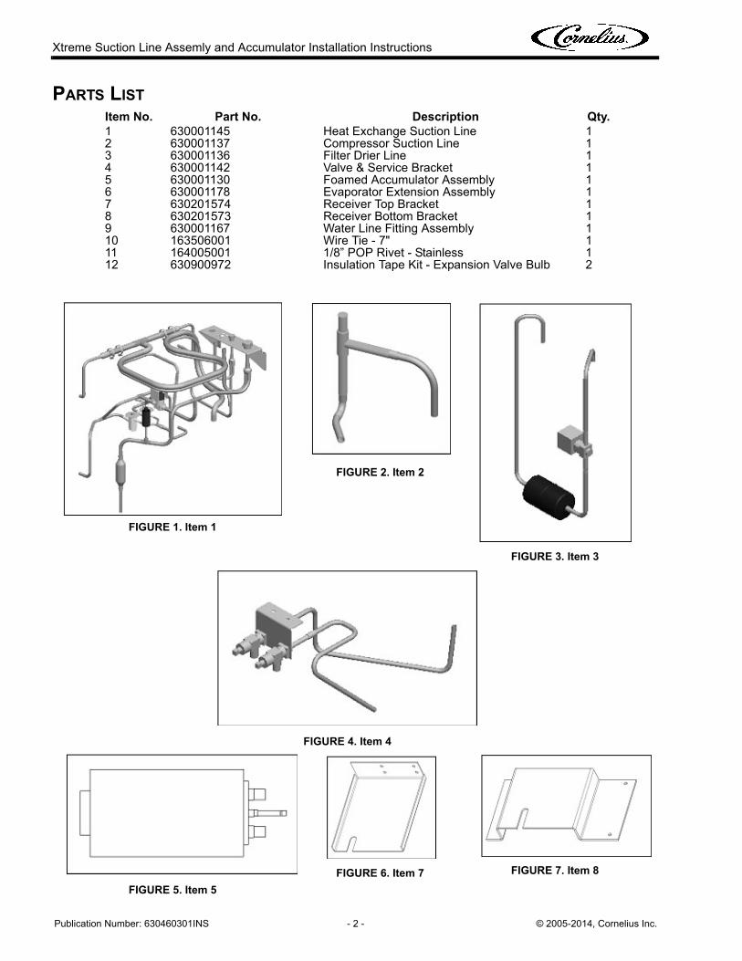
51. Place the back panel in the unit. Attach the Aeroquip bracket with (4) hex head screws (FIGURE 47).Do NOT attach to the left side panel at this time.
FIGURE 47
52. Place the right side panel / brace / electrical box assembly (FIGURE 47).Attach the right side panel to the base with the 1/8” stainless POP rivet (FIGURE 48).
FIGURE 48
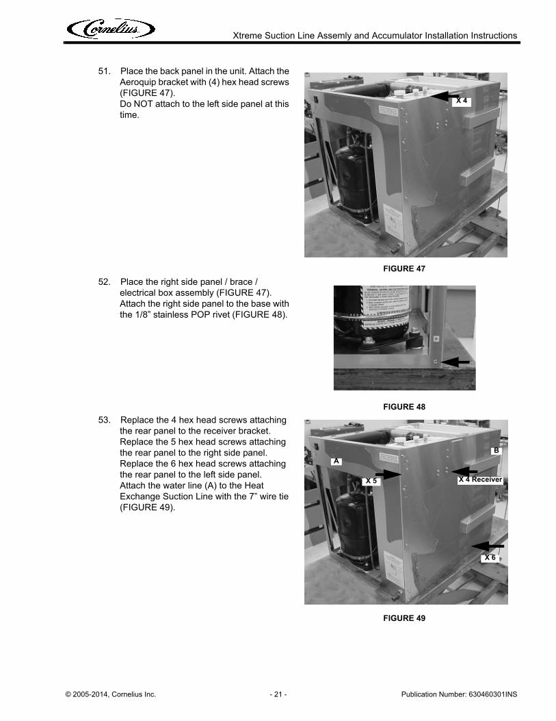
53. Replace the 4 hex head screws attaching the rear panel to the receiver bracket.Replace the 5 hex head screws attaching the rear panel to the right side panel.Replace the 6 hex head screws attaching the rear panel to the left side panel.Attach the water line (A) to the Heat Exchange Suction Line with the 7” wire tie (FIGURE 49).
FIGURE 49
X 4
A
X 4 Receiver
X 6
X 5
B
Xtreme Suction Line Assemly and Accumulator Installation Instructions
Publication Number: 630460301INS - 22 - © 2005-2014, Cornelius Inc.
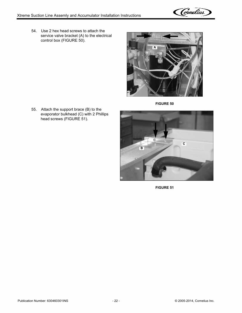
54. Use 2 hex head screws to attach the service valve bracket (A) to the electrical control box (FIGURE 50).
FIGURE 50
55. Attach the support brace (B) to the evaporator bulkhead (C) with 2 Phillips head screws (FIGURE 51).
FIGURE 51
A
CB

Xtreme Suction Line Assemly and Accumulator Installation Instructions
© 2005-2014, Cornelius Inc. - 23 - Publication Number: 630460301INS
NOTE: VERIFY ALL ELECTRICAL CONNECTIONS AGAINST THE UNIT WIRING DIAGRAM.
56. Connect the compressor (FIGURE 52) and replace the junction box cover.
Connect the Curtain Switches (A) to the control board. Replace the rubber grommet in the control box to protect the low voltage wiring.
FIGURE 52
Connect the pressure switch (B) to the #5 pin on the control board, and to the contactor (FIGURE 53).
Connect the crankcase heater (C) to the line side of the contactor.
FIGURE 53
Black
Red
Yellow
A
B
C
B
C

Xtreme Suction Line Assemly and Accumulator Installation Instructions
Publication Number: 630460301INS - 24 - © 2005-2014, Cornelius Inc.
57. Connect the water fill valve harness (A) (black and white leads) and the water dump valve harness (B) (yellow and white leads) (FIGURE 54).
FIGURE 54
58. Connect the hot gas valve harness (C) (white and red leads) to the hot gas valve (FIGURE 55).
59. Connect the liquid line valve harness (black and red leads).
VERIFY ALL ELECTRICAL CONNECTIONS AGAINST THE UNIT WIRING DIAGRAM.
FIGURE 55
A
B
C

Xtreme Suction Line Assemly and Accumulator Installation Instructions
© 2005-2014, Cornelius Inc. - 25 - Publication Number: 630460301INS
60. Connect the pressure transducer tube (D) to the water pan.Connect the water pump motor harness (E) (FIGURE 56).Do NOT fill the water pan.
61. Connect the ground lead from the control box to the base plate, by the compressor.
FIGURE 56
62. If the water supply line was disconnected, reconnect at this time.
63. Evacuate the system, in preparation for charging with refrigerant. Recommended pre-charge system state is 150 microns. Do NOT run the compressor with the system in vacuum.
64. TURN ON THE SUPPLY WATER.
65. Crack the system with R-404A (HP-62) on the low side service valve.
Do NOT introduce liquid refrigerant into the low side service valve, or any other part of the system.
Charge the unit with R-404A (HP-62) refrigerant to the specification on the serial plate on the icemaker AND on the remote condenser.
It is the policy of Cornelius, Inc. to:
A. Comply with all federal regulations concerning the handling of refrigerants.
B. Allow only virgin or reclaimed refrigerant (as defined by ARI Standard 740-91) to be used as or added to an original system charge.
C. Allow recycled refrigerant to be used only in the system from which it was originally recovered; and only if that system did NOT have a compressor burn out or refrigerant leak; and only if moisture, non-condensables, or other contaminants were NOT present in that system.
D. Refrigerant recovered from a contaminated system such as a compressor burn-out, refrigerant leak, or one that has moisture, air, or other non-condensables present, must be disposed of in an appropriate manner and cannot, under any circumstances, be reused in any Cornelius product. If the refrigerant has been reclaimed and meets ARI Standard 700-88, it can be used.
E. The refrigerant used to recharge a Cornelius product must be of the type specified on the serial nameplate of that product. All refrigerants must be weighed into the system so the amount of the charge is known and agrees with the product serial nameplate.
IMPORTANT: The service contractor is responsible for determining if the refrigerant is contaminated. It is also their responsibility to assure their recycling equipment and procedures will guarantee that the refrigerant clean, moisture and non-condensable free and meets the appropriate standard. If the refrigerant is not cleaned to the appropriate standard, the warranty will be voided and the repair will become the responsibility of the service contractor.
Always follow safe and acceptable refrigeration procedures.
66. Once the system has been properly charged, monitor the unit for 3-4 freeze / harvest cycles. Refer to the operating manual for details on proper unit operation and performance.
E
D

Xtreme Suction Line Assemly and Accumulator Installation Instructions
Publication Number: 630460301INS - 26 - © 2005-2014, Cornelius Inc.
67. After verifying the proper operation of the unit, replace the electrical control box cover (A) using (1) Phillips head screw.
Replace the evaporator splash panel (B) (FIGURE 57).
FIGURE 57
68. Replace the top cover (C) and the front panel (D). Attach the louvered panel with (4) black, hex head screws (FIGURE 58).
FIGURE 58
A
B
D
C
X4
Related Documents