1

Welcome message from author
This document is posted to help you gain knowledge. Please leave a comment to let me know what you think about it! Share it to your friends and learn new things together.
Transcript

1

2
3
Successful Industry Collaborations for Evaluating
the Performance of Safer Chemical Alternatives
Greg Morose Research Manager, Toxics Use Reduction Institute
Research Professor, University of Massachusetts Lowell

Webinar Agenda
4
• Alternatives Assessment Overview
• Example 1: Lead-free electronics
• Example 2: Hex chrome free coatings
• Results/Benefits/Lessons Learned

What is Alternatives Assessment?
A process for identifying and comparing potential chemical, material, product, or other alternatives that can be used as substitutes to replace chemicals of high concern.
• Reduce risk by reducing hazard • Move from problems to solutions • Avoid regrettable substitutions • Encourage transparency, common language,
and documentation to communicate among stakeholders
Goals

6
Alternatives Assessment
6
EHS Cost/ Financial
Technical/ Performance
Is it safer? Is it affordable? Will it work?
• Flammability? • Human toxicity? • Animal toxicity? • Ozone depletion? • Persistence? • Bioacummulative? • Etc.
• Materials? • Regulatory compliance? • Insurance? • Training? • Equipment? • Utilities/energy? • Etc.
• Process changes? • Equipment changes? • Material compatibility? • Product quality? • Produce longevity? • Customer specifications? • Etc.

TURI Conditions for Industry Collaboration
7
1. Use of a toxic chemical(s) of concern is pervasive in an industry sector
2. Toxic chemical is not used for competitive advantage (pre-competitive)
3. Strong market and/or regulatory drivers to reduce the use of the toxic chemical
4. Significant research required to switch to the use of safer alternatives
5. Time and cost intensive for companies to individually conduct research
6. Independent third party available to manage and coordinate the effort
7. Voluntary participation by government, academic, and industry collaborators
8. Participants provide either in-kind contributions (production equipment, technical expertise, materials, supplies, testing, etc.) or direct funding
9. Intent of participants is to adopt the safer alternative solutions identified
10.All results made public so that other companies can adopt solutions identified

8
Project Example 1: Lead-free Electronics 2001 – 2011 Project Example 2: Hex Chrome-free Coatings 2012 - ??

TURI Project: Lead-free Electronics
9
Toxic Chemical of Concern
Lead: acute & chronic health effects
Industry
Electronics products: sales of about $1 trillion each year
Use Solder, solder paste, board surface finish, component surface finish
Volume 80 – 90 million pounds used globally on an annual basis
Driver EU Directive: Restriction on the Use of Certain Hazardous Substances (RoHS)
Research Required Technical performance of alternatives for assembly, rework, and long term reliability
Collaborative Research Approach
Formation of the New England Lead-free Electronics Consortium

10 10
Lead Basics – Inherent Properties
• Low melting temperature • Conducts electricity • Very ductile (malleable) • Slow to corrode • Relatively abundant and inexpensive • High density • Attenuation of radiation and sound • Lead alloys and lead compounds have
other useful properties

11
Alternatives Have Tighter Processing Window
218
260
42 °C
183
Component Upper Design Spec Limit
248
217
12 °C
(60 - 90 seconds above liquidus)
Tin / Silver / Copper profile (Lead-Free)
Tin / Lead profile
°C
Higher thermal stresses to components and boards.

12
Lead-free Electronics Industry Challenges
4. What process modifications?
2. Which lead-free board finishes?
3. Which lead-free component finishes?
1. Which lead-free solders?
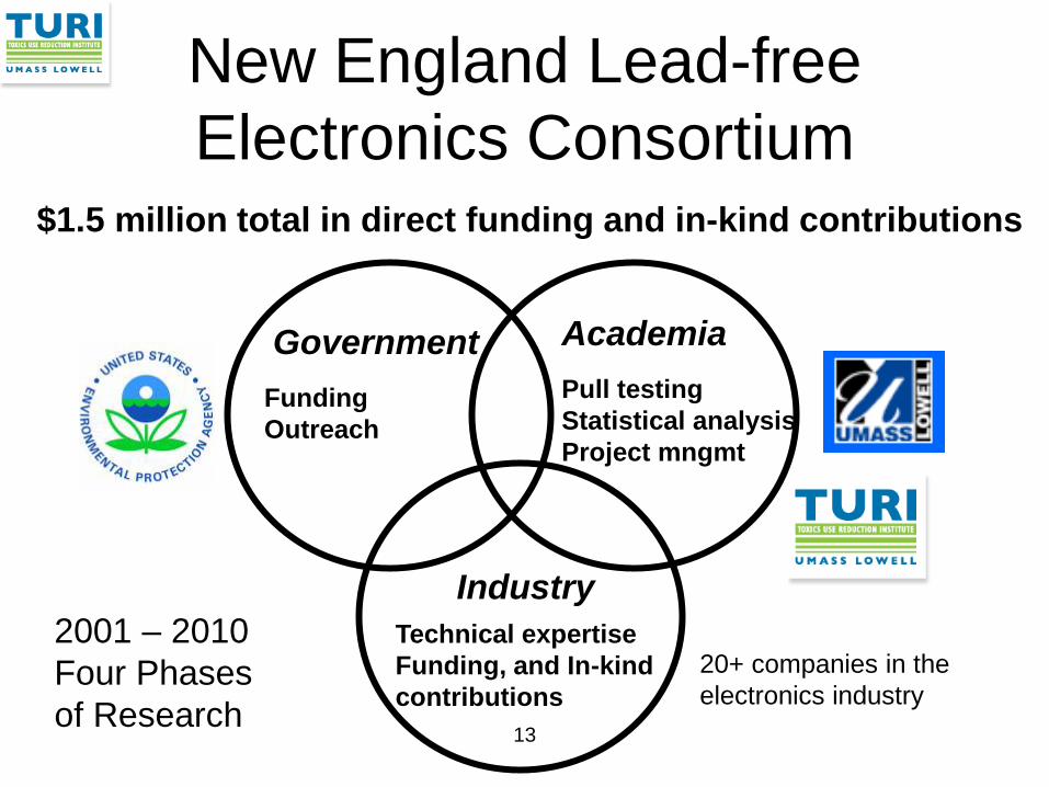
New England Lead-free Electronics Consortium
13
Government Academia
Industry
Pull testing Statistical analysis Project mngmt
Funding Outreach
Technical expertise Funding, and In-kind contributions
$1.5 million total in direct funding and in-kind contributions
20+ companies in the electronics industry
2001 – 2010 Four Phases of Research

14
Electronics Assembly Process
Component Pick & Placement
SMT Reflow Oven Solder Paste Printing
Repair/rework THT Soldering
X-ray & Optical Inspection

THT Soldering: Process Variables
15
Flux Process Variables
Flux type
Flux speed
Aperture opening time
Pressure
Nozzle diameter
Nozzle to board gap
Frequency (how fast the plunger is moving up and down)
Preheat Process Variables
Target temperature
Temperature delta across board Preheat type
Preheat duration
% Power
Preheat area
Certain lamps on/off
Soldering Process Variables
Solder pot temperature
Dwell time
Wait time before dwell
Drag speed
Speed solder is pulled from board Board drop speed to nozzle
Nozzle to board gap
Nozzle sizes
Nozzle design
Height of solder in nozzle
Solder alloy
Solder flush cycle
26 Process Variables

Factors and Levels
16
A factor is an independent variable that is an input to a process. A level is a variable that constitutes different levels of a factor.
Type of Factor Factor Levels Attribute data Flux type
Vendor A, Vendor B, etc.
Continuous data Solder Pot Temp. (degrees C)
290, 300, 310, 320, etc.

17
Six Sigma - DMAIC Measure Analyze Improve Control
Initiate the Project
Define the Process
Determine Customer Requirements
Define Key Process Output Variables
Verify Critical Inputs Using Planned Experiments
Design Improvements
Pilot New Process (Implement)
Analyze Data to Prioritize Key Input Variables
Identify Waste
Finalize the Control System
Verify Long Term Capability
Understand the Process
Evaluate Risks on Process Inputs
Develop and Evaluate Measurement Systems
Measure Current Process Performance
Define

18
Six Sigma Approach
• Need to switch from lead based solders to lead-free solder materials in electronics products. Problem Statement
• Successfully use lead-free solder materials to achieve equivalent or better solder performance for product manufacture, repair, and longevity.
Goal
• Manufacture: Defects per unit • Rework: Copper dissolution • Longevity/Reliability: Cycles to failure
Key Process Outputs
Key Process Inputs • Reflow profile, solder paste, print speed, surface finish, component finish, laminate material, etc.

19
The Outputs (Y’s) are determined by the Inputs (X’s). If we know enough about our X’s we can accurately predict Y.
• Y1: Defects per unit (assembly)
• Y2: Copper dissolution (rework)
• Y3: Cycles to failure (reliability)
Solder joint integrity = (reflow profile, solder paste, print speed, surface finish, component finish, laminate material, etc.)
) x ,..., x , x , f(x = Y k 3 2 1
Problem Solving Approach

20 20
Critical Input Variables
30+ Inputs
8 - 10
4 - 8
DEFINE
3 - 6
Cause & Effect Diagrams 10 - 15
Literature search
Technical expert input
FMEA
Refined experiments
Detailed, focused experiments
Screening level experiments
Determine Critical Inputs Trivial Many
Critical Few
Industry specifications

Research Overview
21
Phase Test Vehicle (Experimental Printed
Circuit Board)
Factors Investigated Results
Phase One 2001 - 2002
Experimental Board: Single layer, single sided, surface mount components only, low component density.
LF solder alloys (3) Thermal profiles (2) Reflow environments (2) Surface finishes (2)
• Lead-free soldering with equal or less defects than lead soldering is possible with experimental boards.
• After thermal cycling, the strength of lead-free solder joints is comparable to lead solder joints for experimental boards.
• Decision to focus on tin/silver/copper alloy and a ramp to peak thermal profile for reflow processes.
Phase Two 2002 - 2004
Experimental Board: Single layer, single sided, surface mount components only, low component density.
LF Solder Alloys (1) Thermal profiles (1) Reflow environment (2) Surface finishes (5)
• Decision to focus on air only atmosphere for reflow environment.
• Decision to focus on 3 printed circuit board surface finishes: ENIG, OSP, and Immersion silver.

Research Overview
22
Phase Test Vehicle (Experimental Printed Circuit Board)
Factors Investigated Results
Phase Three 2004 - 2007
Production Like Board: 20 layers, double sided, surface mount and through hole components, high component density.
LF Solder Alloys (1) Thermal profiles (1) Reflow environment (1) Surface finishes (3) Laminate materials (2)
• Lead-free soldering with equal or less defects than lead soldering is possible for production like boards.
• Decision to use Isola HR370 laminate material as baseline lead-free laminate material for upcoming experiments.
Phase Four 2008 - 2011
Production Like Board: 20 layers, double sided, surface mount and through hole components, high component density.
LF Solder paste alloys (1) THT solder materials (2) Thermal profiles (1) Reflow environment (1) Surface finishes, including one with nanomaterials (4) Laminate materials including halogen and non-halogen (2)
• Successful single and double rework efforts are possible with lead-free materials that can achieve Class 3 standards without signs of thermal degradation.
• Long-term reliability results of lead free materials were mixed for the various component types investigated.
• The halogen-free laminate materials had early failures during thermal cycling and require reformulation before additional reliability testing.

23
Test Vehicle (Phase IV)
• 8” wide x 10” long • 20 layers • 0.110 inches thick • 907 components per
test vehicle
SMT Components: THT Components: Connectors, LEDs, capacitors, DC/DC Convertors, TO220
Resistors, BGAs, microBGAs, PQFN, TSSOP, PQFP, MLF, Transformer
Test Vehicle

24
Design Manufacturing
Reliability Testing Board fab
Visual testing
Components
Solder Paste
Process Equipment
New England Lead-free Consortium – Phase III

25
Consortium Communication • Bimonthly consortium meetings
• Distribution of meeting materials and
meeting minutes
• Workgroup documentation and presentation of results for specific issues (i.e. FMEA, board design, rework, etc.)
• Surveys, Workshops
• Develop papers for submission to electronics publications and electronics conferences
• Presentation at major electronics conferences
• Maintain consortium website

26
Contributions for Four Phases Contributions
Production equipment and technical support
Analysis and project management
U.S. EPA funding
Engineering support
Testing, inspection, and support
Components and materials
TOTAL VALUE: > $1.5 million

27
Cause and Effect Diagram Example
ComponentsSMTIntegritySolder JointAssembly:
Environment
Measurements
Methods
Material
Machines
Personnel
Experience lev el
P lacement
Reflow
Printing
Stencil materialF inishC omponent
Solder Paste
Surface F inish
Laminate
DFM
Shelf life
Bake out
A perture
Ramp to peak
Inspector Training
StandardsV isual Inspection
C leanliness
env ironmentReflow
# C ooling
# Heating
temperatu
PeakTA
V endor
C hemistry
A lloy
V endor
C hemistry
A lloy
ThicknessSty le
Size
New England Lead-free Electronics Consortium

28
Failure Mode and Effects Analysis
(FMEA)
Process Step/Input Potential Failure Mode Potential Failure Effects
SEV
Potential CausesOCC
Current ControlsDET
RPN
Actions Recommended
0 0 0 0
0 0 0 0
0 0 0 0
0 0 0 0
0 0 0 0
What is the Input
What can go wrong
with the Input?
What can be done?
What is the Effect
on the Outputs?
What are the
Causes?
How can these be found or
prevented?
How Bad?
How Often?
How well?

Effects Causes Controls RPN = Severity X Occurrence X Detection
Risk Priority Number (RPN)
• The RPN is an output of FMEA • The RPN is used assist in the
prioritization of items in the FMEA based on three characteristics – Severity of the Effects – Occurrence of the Causes – Detection capabilities of current Controls

30
Design of Experiments
Board SMT Solder Paste Through Hole
Solder Surface Finish PWB Laminate
1 Tin/lead Tin/lead ENIG High Tg FR4
2 Tin/lead Tin/lead ENIG High Tg FR4
3 Tin/lead SAC305 LF HASL High Tg FR4
4 Tin/lead SAC305 LF HASL High Tg FR4
5 SAC305 NC-1 Tin/Copper OSP Halogen free FR4
6 SAC305 NC-1 Tin/Copper OSP Halogen free FR4
7 SAC305 NC-1 SAC305 Nanofinish Halogen free FR4
8 SAC305 NC-1 SAC305 Nanofinish Halogen free FR4
Lead-free Test Vehicles, Boards 1 – 8 (illustrative only)

Hex Chrome – Uses in Defense/Aerospace Applications
31
• Sealants • Primers • Conversion coatings
Health Effects: • IARC Group 1 (carcinogenic to humans) • Mutagen and developmental toxicant • Long term inhalation can cause lung cancer, and
can also result in perforation of the nasal septum and asthma.
Driver for Change: Defense Federal Acquisition Regulation Supplement (DFARS) , May 2011

Sealant Research Overview
32
Research Phase
Timeframe
Purpose Materials Evaluated
Phase I 2012 Screening level information for sealant performance
4 sealants 2 conversion coatings 2 aluminum alloys 2 primers 2 fastener types With & without topcoat
Phase II 2013 • DFARs compliance for sealants
• Sealant removal evaluation
6 sealants
Phase III 2014 Totally hex chrome free stack-up: conversion coating, sealant, primer, & topcoat
To be determined

Contributors to Phase I Research
33
Government
Academia Industry

Test Vehicle Assembly Drawing
34
8 stainless steel fasteners (4 with countersunk heads, and 4 with socket heads)
Aluminum plates: 2” x 4.5” x 0.25” (alloys 6061 and 7075)

35
Lead-free Electronics: Results, Benefits, and Lessons Learned

Collaborative Research Results
36
Successful Research Results
Demonstrated that electronics assembly & rework with lead-free materials can be done with equal or fewer defects than lead.
Adoption of Safer Materials
Consortium members were able to initiated their own lead-free electronics programs. For example, Benchmark Electronics has now manufactured approximately 9 million lead-free printed circuit boards to date.
Outreach Published and presented the results of research efforts widely, including more than 40 papers, articles, and presentations for national and international professional conferences and technical journals.

University Member Benefits
37 37
Hands on laboratory efforts for real world learning and research experience.
Faculty/Student presentations at industry conferences.
Forged collaborative relationships between university and regional businesses that have led to additional UML research projects. Increased university faculty experience in applied science and engineering.

38
Government Member Benefits
Government
Reduced the use of a toxic material (lead) which leads to a safer occupational setting and an improved environment. Improved the competitive position of local businesses by addressing industry challenges in a proactive and efficient manner.

39
Industry Member Benefits Industry
Ability to have input and influence on consortium efforts (e.g. material selection, supplier selection, testing strategies, etc.). Access to cutting edge research and analysis. Ability to share the costs to address a major industry challenge. Forum provided to share ideas and receive advice from industry peers. Ability to derive competitive advantage for early preparedness. Individual: Become a knowledge leader within organization.

TURI Collaborations: Key Success Factors
40
• Standards: Adopt relevant standards when feasible (performance, testing, inspection, etc.). Deviate from relevant standards when necessary (with justification).
• Methodology: Use Six Sigma DMAIC process and tools as appropriate.
• Value: Want value received from participation in consortium to be greater than the cost of participation
• Transparency: All members involved in decisions. Evaluation results are documented and become publicly available.
• Balance: Identify intersection/overlap of research interests among participants. Don’t allow individual participants to dominate the direction of the group.
• Responsiveness: Timely response to participant inquiries and concerns.
• Communication: Not too much (be respectful of people’s time), and not too little (keep them informed of major decisions and milestones).
• Detailed analysis: Work out details with assigned subgroups, and present results and decisions to entire group.

41
Related Documents