Subsurface Exploration and Geotechnical Evaluation Hotel at 13311 Burnet Road (MoPac) Austin, Texas Prepared for: Visvanath, LP 3120 Montopolis Drive Austin, Texas 78744 Prepared by: Capital Geotechnical Services PLLC Cedar Park, Texas Texas Engineering Firm Registration # 9458 Capital Geotechnical Services Project # 15-0179 November 1, 2015 Nicholas F. Kauffman, M.S., P.E. Principal Geotechnical Engineer

Welcome message from author
This document is posted to help you gain knowledge. Please leave a comment to let me know what you think about it! Share it to your friends and learn new things together.
Transcript
Subsurface Exploration and Geotechnical Evaluation
Hotel at 13311 Burnet Road (MoPac) Austin, Texas
Prepared for:
Visvanath, LP 3120 Montopolis Drive
Austin, Texas 78744
Prepared by:
Capital Geotechnical Services PLLC Cedar Park, Texas
Texas Engineering Firm Registration # 9458
Capital Geotechnical Services Project # 15-0179
November 1, 2015
Nicholas F. Kauffman, M.S., P.E.
Principal Geotechnical Engineer

Hotel at 13311 Burnet Road (MoPac), Austin, Texas Capital Geotechnical Services Project #15-0179
TABLE OF CONTENTS Page:
SCOPE .......................................................................................................................................................... 1
SUMMARY .................................................................................................................................................... 1
SITE LOCATION AND CONDITIONS .......................................................................................................... 3
LANDFILL LITERATURE REVIEW ............................................................................................................... 3
PROPOSED DEVELOPMENT AND CONSTRUCTION ............................................................................... 4
GEOLOGY AND SOIL MAPPING INFORMATION ...................................................................................... 4
SUBSURFACE EXPLORATION ................................................................................................................... 5
LABORATORY TESTING ............................................................................................................................. 5
SUBSURFACE CONDITIONS ...................................................................................................................... 6
POTENTIAL MOVEMENT OF THE CLAY SOILS ........................................................................................ 7
SITE PREPARATION AND EARTHWORK .................................................................................................. 8
FOUNDATIONS .......................................................................................................................................... 13
Drilled Pier Option................................................................................................................................. 14
Stiffened Slab Option ............................................................................................................................ 17
Driven Steel Pipe Piles ......................................................................................................................... 22
STRUCTURALLY SUPPORTED SLAB (if used) ........................................................................................ 22
SEISMIC DESIGN ....................................................................................................................................... 23
PAVEMENT THICKNESS DESIGN ............................................................................................................ 23
CONCRETE PAVEMENT COMMENTARY ................................................................................................ 26
PAVEMENT MAINTENANCE ..................................................................................................................... 27
PAVEMENT MATERIAL RECOMMENDATIONS AND TESTING ............................................................. 28
SURFACE DRAINAGE, VEGETATION, AND UTILITY CONNECTIONS .................................................. 33
POST-TENSIONING (IF USED) ................................................................................................................ 34
LIMITATIONS .............................................................................................................................................. 35
INSPECTIONS ............................................................................................................................................ 36
FIGURES: Figure 1: Vicinity Map Figure 2: Local Lot Plan Figure 3: Geology Map Figure 4: Approximate Locations of Exploratory Borings Figure 5 to Figure 8: Boring Logs Figure 9: Standard Reference Notes for Boring Logs Figures 10 and 11: Swell Test Results Figure 12: City of Austin Landfill Check Form

Hotel at 13311 Burnet Road, Austin, Texas Capital Geotechnical Services PLLC Project #15-0179
1
SCOPE
This report presents the results of a geotechnical evaluation for a proposed 3-story hotel
building on the northbound frontage road of the MoPac Expressway in Austin, Texas. This study
was performed to evaluate subsurface conditions and to provide recommendations for the design
and construction of the foundation system and for pavement thickness design. Capital
Geotechnical Services PLLC performed this subsurface exploration and geotechnical evaluation
in accordance with our proposal # P15-0081 authorized (signed) on September 17, 2015.
The scope of services for this study included the determination of subsurface conditions
through field and laboratory testing, an evaluation of the subsurface conditions relative to the
proposed construction, and the preparation of a geotechnical report. This report includes results,
evaluations, and recommendations concerning earthwork, foundations, groundwater, pavement,
quality control testing, and other geotechnical related aspects of the project. A summary of our
conclusions is presented in the following section of this report. More complete descriptions and
findings of our field and laboratory testing are presented in the rest of the report.
The scope of services did not include any environmental site assessments (ESAs) for the
presence or absence of wetland or hazardous or toxic materials in the soil, air, surface water, or
groundwater at this site.
SUMMARY
The subsurface conditions encountered during our exploration and our geotechnical
engineering evaluations and recommendations are summarized in the following paragraphs. This
summary should not be considered apart from the entire text of this report. This report should be
read and evaluated in its entirety prior to using our engineering recommendations for the
preparation of design or construction documents. Details of our findings and recommendations
are provided in subsequent sections of this report and in the attached figures.
1. Four (4) exploratory borings were drilled to evaluate soil conditions. The subsurface
profile varies slightly among the boring locations. At borings B-1 and B-2 (southeast area
of site) the subsurface profile consisted of 5 to 6 feet of dark grayish brown, light gray,
light yellowish brown, medium grayish brown, and medium yellowish olive-brown highly
plastic clay and gravel with some sand content (CH and GC classifications), overlying a
massive stratum of light gray, light yellowish brown, and light olive-brown highly plastic
clay (“Del Rio Cay”) to a depth of at least 30 feet. At boring B-3 the surface stratum (upper
6 feet) of dark brown and medium yellowish brown clay only contained trace gravel content
and was underlain by the massive highly plastic “Del Rio Clay”. At a 4th boring location
the surface stratum (8 feet thick) of dark brownish gray and medium yellowish brown clay
was only moderately plastic (CL) beyond a depth of 2 feet. Groundwater was not

Hotel at 13311 Burnet Road, Austin, Texas Capital Geotechnical Services PLLC Project #15-0179
2
encountered during the drilling operation in October 2015. The maximum depth of
exploration was 30 feet.
2. The “Del Rio Clay” can be susceptible to significant swelling and shrinkage potential. The
TxDOT PVR site index was calculated to range between 2 ½ inches to 3 ¾ inches due to
the plasticity and soil profile (gradation). Potential vertical soil movement (design PVR)
however was calculated to be over 7 inches at the surface if no soil improvement is
performed and notable changes in moisture content occur within an active zone 15 feet
deep. The design PVR under a lightly to moderately loaded foundation slab was
calculated to be 5 ½ inches to 7 inches if no soil improvement is performed and notable
changes in moisture content occur post-construction within a 15-ft deep active zone.
3. Based on the available soil information, proposed construction, and assumed structural
loads, the project team can consider two foundation options:
Option A: The approximately 9,100 square-foot building can be constructed on a
structurally supported slab cast on void boxes and constructed on deep concrete belled
drilled piers. Recommendations concerning the design and construction of the drilled
piers are presented in this report. Recommendations concerning a driven steel pipe pile
alternative to concrete drilled piers can be provided upon request.
Option B: Perform significant soil improvement and construct the 3-story building on a
ground-supported stiffened slab foundation system (foundation slab). The building must
be designed to accommodate some differential soil movement. Various options for soil
improvement and foundation slab design are presented in this report.
4. Based on a finished floor elevation assumed to be close to existing grade at the upslope
side of the building, we assume 4 inches to 40 inches of fill will be required to reach
planned slab subgrade elevation across the footprint before consideration of any soil
improvement. Recommendations concerning earthwork and pavement thickness design
are also included in this report.
5. Surface drainage should be designed, constructed, and subsequently not adversely
altered by the Owner, to provide rapid removal of water runoff away from all sides of the
building and away from the edges of pavement or flatwork.
Hotel at 13311 Burnet Road, Austin, Texas Capital Geotechnical Services PLLC Project #15-0179
3
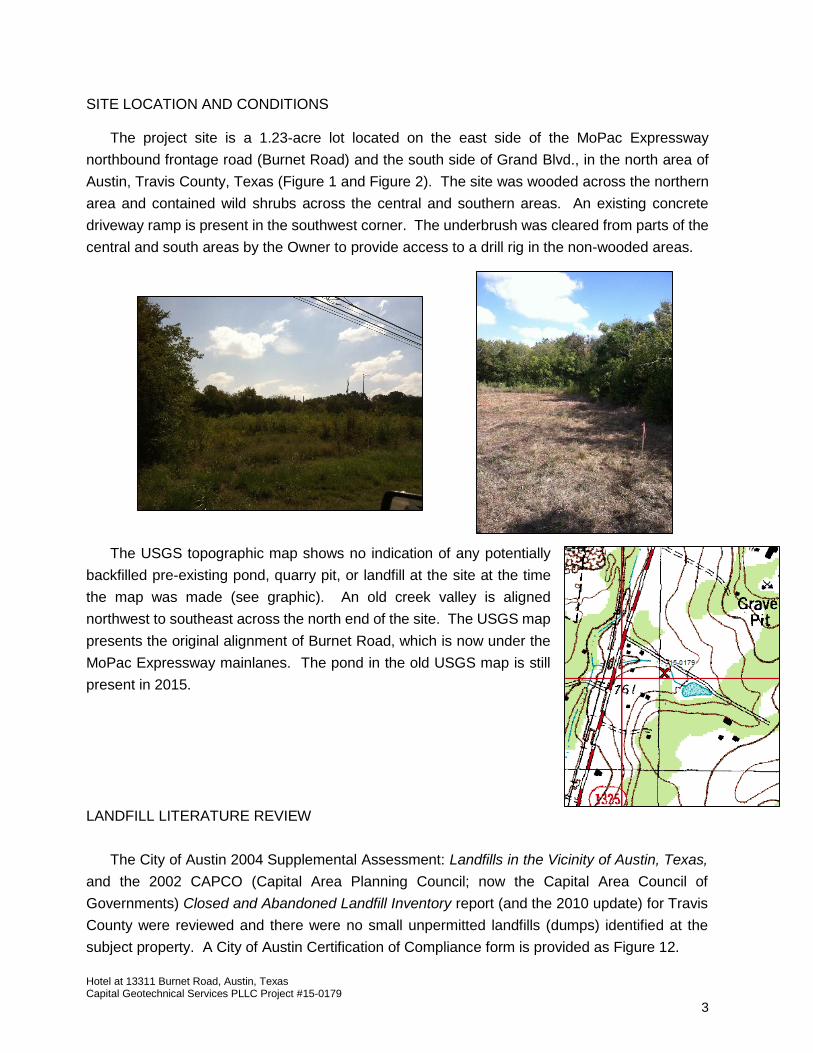
SITE LOCATION AND CONDITIONS
The project site is a 1.23-acre lot located on the east side of the MoPac Expressway
northbound frontage road (Burnet Road) and the south side of Grand Blvd., in the north area of
Austin, Travis County, Texas (Figure 1 and Figure 2). The site was wooded across the northern
area and contained wild shrubs across the central and southern areas. An existing concrete
driveway ramp is present in the southwest corner. The underbrush was cleared from parts of the
central and south areas by the Owner to provide access to a drill rig in the non-wooded areas.
The USGS topographic map shows no indication of any potentially
backfilled pre-existing pond, quarry pit, or landfill at the site at the time
the map was made (see graphic). An old creek valley is aligned
northwest to southeast across the north end of the site. The USGS map
presents the original alignment of Burnet Road, which is now under the
MoPac Expressway mainlanes. The pond in the old USGS map is still
present in 2015.
LANDFILL LITERATURE REVIEW
The City of Austin 2004 Supplemental Assessment: Landfills in the Vicinity of Austin, Texas,
and the 2002 CAPCO (Capital Area Planning Council; now the Capital Area Council of
Governments) Closed and Abandoned Landfill Inventory report (and the 2010 update) for Travis
County were reviewed and there were no small unpermitted landfills (dumps) identified at the
subject property. A City of Austin Certification of Compliance form is provided as Figure 12.

Hotel at 13311 Burnet Road, Austin, Texas Capital Geotechnical Services PLLC Project #15-0179
4
PROPOSED DEVELOPMENT AND CONSTRUCTION
The proposed development includes a 3-story, approximately 9,100 square-foot, hotel
building with associated parking lot paving. A site plan was provided to Capital Geotechnical
Services and was used for the boring location plan (Figure 4).
Information concerning structural loads was not provided to Capital Geotechnical Services.
We have assumed that the building will consist of wood framing and structural loads will not
exceed 75,000 lbs for any column loads and 3,000 lbs per foot for wall loads.
Information concerning planned finished floor (FF) elevation and existing topographic ground
surface elevation data was not provided to Capital Geotechnical Services by the time of this
report. We have therefore assumed that planned finished floor elevation will be close to, but just
above, existing grade on the upslope side of the building (i.e. FF elevation 8 inches above upslope
grade). Based on a cursory observation of the site, there appears to be approximately 3 feet of
ground surface elevation difference across the planned building footprint area. Therefore we
assume 4 inches to 40 inches of fill will be required to reach planned slab subgrade elevation
before consideration of soil improvement. We assume minor cut and fill grading will be required
to reach planned pavement subgrade elevation and to accomplish final grades for drainage
design purposes.
If the proposed construction varies from what is described in this report, Capital Geotechnical
Services must be contacted to determine if revisions to our recommendations are required.
GEOLOGY AND SOIL MAPPING INFORMATION
According to the USDA Natural Resources Conservation Service shallow soil mapping
information, the shallow soils (upper 5 feet) of the project site may be a member of the “Heiden
Clay” soil series. This soil generally classifies according to the USCS as fat clay (CH). According
to the survey, the soil is commonly dark grayish brown and is commonly mapped above the “Del
Rio Clay” formation.
According to available geology mapping information by the U.T. Bureau of Economic Geology,
the site is located in the “Balcones Escarpment” (fault zone) geologic physiographic province and
consists of a clay sedimentary deposit categorized as the “Del Rio Clay” geologic formation. The
local area is faulted and a limestone rock sedimentary deposit categorized as the “Georgetown
Limestone” formation might be present along the west area of the site. A geology map is provided
in Figure 3.
Hotel at 13311 Burnet Road, Austin, Texas Capital Geotechnical Services PLLC Project #15-0179
5
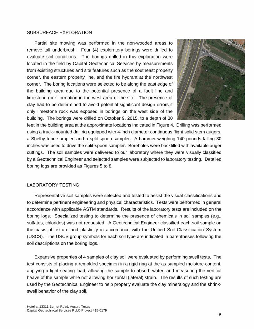
SUBSURFACE EXPLORATION Partial site mowing was performed in the non-wooded areas to
remove tall underbrush. Four (4) exploratory borings were drilled to
evaluate soil conditions. The borings drilled in this exploration were
located in the field by Capital Geotechnical Services by measurements
from existing structures and site features such as the southeast property
corner, the eastern property line, and the fire hydrant at the northwest
corner. The boring locations were selected to be along the east edge of
the building area due to the potential presence of a fault line and
limestone rock formation in the west area of the site. The presence of
clay had to be determined to avoid potential significant design errors if
only limestone rock was exposed in borings on the west side of the
building. The borings were drilled on October 9, 2015, to a depth of 30
feet in the building area at the approximate locations indicated in Figure 4. Drilling was performed
using a truck-mounted drill rig equipped with 4-inch diameter continuous flight solid stem augers,
a Shelby tube sampler, and a split-spoon sampler. A hammer weighing 140 pounds falling 30
inches was used to drive the split-spoon sampler. Boreholes were backfilled with available auger
cuttings. The soil samples were delivered to our laboratory where they were visually classified
by a Geotechnical Engineer and selected samples were subjected to laboratory testing. Detailed
boring logs are provided as Figures 5 to 8.
LABORATORY TESTING
Representative soil samples were selected and tested to assist the visual classifications and
to determine pertinent engineering and physical characteristics. Tests were performed in general
accordance with applicable ASTM standards. Results of the laboratory tests are included on the
boring logs. Specialized testing to determine the presence of chemicals in soil samples (e.g.,
sulfates, chlorides) was not requested. A Geotechnical Engineer classified each soil sample on
the basis of texture and plasticity in accordance with the Unified Soil Classification System
(USCS). The USCS group symbols for each soil type are indicated in parentheses following the
soil descriptions on the boring logs.
Expansive properties of 4 samples of clay soil were evaluated by performing swell tests. The
test consists of placing a remolded specimen in a rigid ring at the as-sampled moisture content,
applying a light seating load, allowing the sample to absorb water, and measuring the vertical
heave of the sample while not allowing horizontal (lateral) strain. The results of such testing are
used by the Geotechnical Engineer to help properly evaluate the clay mineralogy and the shrink-
swell behavior of the clay soil.
Hotel at 13311 Burnet Road, Austin, Texas Capital Geotechnical Services PLLC Project #15-0179
6
Soil samples that remain after testing will be kept for 3 weeks after the date of this report.
Samples will then be discarded unless we receive instructions regarding their disposition.
SUBSURFACE CONDITIONS
Information from the exploratory borings indicates that the soil stratigraphy may generally
consist of 4 distinguishable strata above a depth of 30 feet. The characteristics of these strata
are summarized in the following paragraphs.
Stratum A: Dark to Medium Clays with Variable Gravel Content
The upper 5 to 6 feet of soil in the building area appears to consist of dark grayish brown, dark
brown, medium yellowish brown, light gray, light yellowish brown, medium yellowish olive-brown,
and medium grayish brown, highly plastic clay with trace gravel and trace sand (CH) and clayey
gravel with sand (GC). The darker colored soil was generally within the upper 2 feet. The gravelly
soils were encountered at B-1 and B-2. SPT N-values ranged between 13 blows per foot (bpf)
and 37 bpf for the 8 tests performed exclusively in this stratum. Two samples of the finer fraction
of the soils were tested to determine plasticity (Atterberg limits) and yielded a liquid limit (LL) of
59% and 61%, and a plasticity index (PI) of 40 and 41. One remolded specimen was subjected
to swell testing and exhibited 26.2% vertical swell (Figure 11) from an initially hard and moderate
moisture condition, indicating the soil has relatively high shrinkage and swelling potential.
Stratum A2: Yellowish Brown Lean Clay
At boring B-4 exclusively, a stratum of light to medium yellowish brown lean clay (CL) (moderately
plastic clay) was evident from a depth of approximately 2 feet to a depth of at least 8 feet. This
soil is slightly different from the shallow soils encountered in the building area but might simply be
of the “Del Rio Clay” geologic formation that frequently includes clay minerology and gradation
that produce a lean clay classification. One sample was tested to determine plasticity and yielded
a LL of 44% and a PI of 29.
Stratum B: “Del Rio” Clay
Beyond a depth of 5 to 6 feet in the building area the soils consisted of light gray, light yellowish
brown, and light olive-brown highly plastic clay (CH) to a depth of at least 30 feet. The soil
included trace white gypsum, trace black mottling, some varved structure with medium gray
lenses, and trace orange-brown color. The clay was very stiff to hard, exhibiting SPT N-values
ranging between 23 bpf to 79 bpf for the 16 tests performed in this stratum. Five samples were
tested to determine plasticity and yielded a LL of 57%, 58%, 64%, 65%, and 66%, and a PI of 37,
39, 40, 43, and 45. Three remolded specimens were subjected to swell testing and exhibited
28.5%, 28.6%, and 32.9% vertical swell from an initially hard condition and moderate moisture
condition, indicating the soil is susceptible to significant shrinkage and swelling movement.
Hotel at 13311 Burnet Road, Austin, Texas Capital Geotechnical Services PLLC Project #15-0179
7
Stratum D: Hard Pale Silty Clay
At boring B-1 exclusively, a stratum of dry to moist, very hard, pale grayish brown lean clay (CL)
was encountered starting at a depth of approximately 22 feet and extended to a depth of at least
30 feet. Some fine sand content was present in the deeper sample. SPT results were 50/5” and
50/4”, indicating the soil was very hard. One sample was tested to determine plasticity and yielded
a LL of 34% and a PI of 19.
The above descriptions are of a generalized nature to highlight the major soil stratification
features and soil characteristics. The boring logs provided in the Appendix should be reviewed
for specific information at each location. The stratification of the soil represents our interpretation
of the subsurface conditions at the boring locations based on observations of the soil samples by
a Geotechnical Engineer. Variations from the conditions shown on the boring logs could occur in
areas in between borings or in areas around the borings. The stratification lines shown in the
boring logs represent approximate boundaries between soil types and condition, and the
transitions may be gradual rather than distinct. It is sometimes difficult to identify changes in
stratification within narrow limits. It may also be difficult to distinguish between fill and discolored
natural soil deposits if foreign substances are not present.
Groundwater was not encountered in our exploratory borings at the time of drilling. Moisture
contents were relatively low, indicating that groundwater was not present. Groundwater, however,
can be temporary instead of perennial. Although groundwater was not encountered during the
drilling and sampling operation, our experience requires us to emphasize that groundwater can
still appear later (e.g. during construction of drilled shafts). The Owner, General Contractor, and
drilling subcontractor should not be surprised if groundwater appears and requires temporary
mitigation measures. Groundwater may develop after periods of rain and can develop after
construction in response to landscaping irrigation or changes to nearby drainage conditions.
Perched groundwater will most likely appear within fissures in the clayey soils.
POTENTIAL MOVEMENT OF THE CLAY SOILS
The clay soils within the zone of seasonal moisture change (or within a potential active zone)
will experience changes in condition due to changes in environmental conditions (rainfall
quantities and frequency; temperature; evaporation; tree roots) and man-made conditions
(leaking water lines; irrigation; poor drainage) that affect the moisture content of the clay soils.
The clay soil may harden, shrink, and crack when subjected to drying, swell when subjected to
wetting, and soften when subjected to saturation.
The TxDOT Potential Vertical Rise (PVR) index (Tex-124-E) considering existing conditions
and existing overburden pressure was calculated to be between 2 ½ inches and 3 ¾ inches based
on the plasticity of the soil and the soil profile (gradation). It was assumed that the clay would be

Hotel at 13311 Burnet Road, Austin, Texas Capital Geotechnical Services PLLC Project #15-0179
8
in an initially “dry” condition as defined by the method at the time of construction and that the
thickness of the active zone is 15 feet. Note that the TxDOT PVR method assumes limited wetting
occurs and should only be used as an index tool for comparing sites. The TxDOT PVR value
should not be considered an estimate of maximum potential vertical heave.
Using reasonable estimates of relatively dry and relatively moist suction profiles or moisture
content profiles and physical properties of the clay soil, the swelling potential of the clay soils
within the active zone (assumed to be 15 feet deep) may be 7 inches or more at the surface under
new flatwork if the moisture content changes between a relatively dry condition and a relatively
moist condition near the surface, tapering to negligible change at a depth of 15 feet. The design
PVR does not consider extreme moisture change conditions (i.e. 200-year to 500-year drought,
rainfall, or groundwater event, etc.) but does consider significant potential changes due to man-
made and environmental conditions. Under a light to moderate foundation slab load, a design
PVR of 5 ¾ inches to 7 inches was calculated considering the same potential changes in moisture
content within the active zone.
The potential amount of total and differential heave or shrinkage is difficult to accurately
predict because it will depend on the extent of impervious cover, seasonal changes in climate
conditions, drainage conditions, presence of leaking water pipes, groundwater conditions,
landscape watering, vegetation planting, thickness of clay soil affected, and varying physical
characteristics and mineralogy of the clay soils. The PVR is not a static value because it depends
on how the soil behavior and the boundary conditions are modeled such as what changes in
moisture content to consider and what initial moisture condition to consider at the time of
construction. Deep-seated swell movements can also occur if swelling of the deeper clay soils is
caused by water sources other than those that affect moisture content variations near the surface
(notable groundwater development; leaking nearby water main; leaking deep sewer pipe; etc).
SITE PREPARATION AND EARTHWORK
The primary geotechnical concern that will influence foundation or slab performance at this
site is the presence of expansive clay soils. We believe that the impact of swelling and shrinking
soils can be mitigated with proper planning, engineering design, and construction quality control
as discussed in this report.
Soil Improvement in the Building Area The potential soil movement due to shrinkage and swelling can be reduced by using soil
improvement techniques to change the characteristics and properties of the subgrade soils.
Options for soil improvement include:

Hotel at 13311 Burnet Road, Austin, Texas Capital Geotechnical Services PLLC Project #15-0179
9
Option 1: Removal of a certain thickness of existing clay soil and replacement with properly
compacted select fill (structural fill).
Option 2: Pre-swelling and modification of clay soil by water and chemical pressure injection
(i.e. “electro chemical injection”, “acid treatment injection”, or “ionic stabilizer injection”; or
potassium chloride injection). A deep perimeter moisture-evaporation barrier might be
required depending on the results of the quality control testing of the injection operation. A
cap of properly compacted select fill will also be required to provide durably stiff subgrade
support immediately under the foundation slab.
Option 1: Removal and Replacement
The thickness of removal and replacement will be selected by the Owner, Architect, and the
Structural Engineer since multiple factors affect how much vertical movement can be tolerated by
the structure (type of cosmetics used, flexibility of framing detailing and cosmetics, aversion to
risk, tolerance to cosmetic cracking and functional distress, stiffness of framing to resist wind
loads, rigidity of slab, design deflection tolerance, etc). Design parameters for various thickness
of soil improvement are provided in this report.
Select fill should extend at least 5 feet beyond the perimeter of the building. Select fill
extending beyond the building footprint should be capped in landscaped areas with an 18-inch
thick clay soil to limit infiltration of surface water into the pad fill.
Option 2: Water and Chemical Pressure Injection
Water and chemical pressure injection is performed by a specialty subcontractor. The
purpose of the water and chemical pressure injection is to pre-swell the existing clay soil and
modify the soil characteristics. The depth of treatment should be 12 feet and the treatment should
extend horizontally at least 5 feet beyond the perimeter of the slab footprint area. The equipment
is typically similar to a tracked dozer equipped with a custom injection rod frame and system.
Injection treatment will require a follow-up investigation to
determine if the method produced the desired pre-swelling and
modifications to the physical properties of the clay soil. The
quality or extent of the modification will partially depend on the
extent of cracking and fissures within the clay strata. The low
permeability of the clay soil and the potential lack of sufficient
cracks will cause the method to not produce a homogeneous
modification of the clay soil. Quality control (QC) testing is
necessary to achieve good quality results.
Hotel at 13311 Burnet Road, Austin, Texas Capital Geotechnical Services PLLC Project #15-0179
10
Completion of the pre-swelling aspect of the injection improvement operation is achieved
when the desired moisture condition is reached. We do not propose any method-based
specifications, only end-result based specifications. After performance of the injection procedure,
drilling and sampling will be required to obtain soil samples. The target moisture condition can
be associated with stiffness and swell potential. Moisture content, pocket penetrometer, and swell
tests will have to be performed to measure the success of the pre-swelling injection operation.
Pocket penetrometer test results should be between 1.0 tsf and 3.5 tsf after a successful injection
operation. The vertical swell of a post-injection sample should not exceed 2% if a remolded
specimen or 1% if an undisturbed sample. Atterberg limits tests and shrink-swell tests will have
to be performed to determine if the chemical compounds changed the physical properties of the
clay soil. Capital Geotechnical Services should be retained to inspect the injection operation to
document means and methods, and the follow-up QC testing should be performed by Capital
Geotechnical Services. The recommended design PVR after a successful injection operation is
1 ½ inches unless the chemical modification aspect is suspected of yielded poor results. If the
quality of the chemical modification is suspect, deep vertical moisture-evaporation barriers must
be installed.
Note that water and chemical pressure injection will produce a soft subgrade. The
construction schedule must allow for at least 2 weeks of “curing” time in the cool season (when
no rainfall is forecast) or 1 week during the summer season after completion of the injection
operation to permit the shallow treated clay soils to dry out and stiffen to support construction
traffic and to permit the proper installation of the first lift of new fill.
Stripping and Clearing
All of the grass topsoil (soil with high organic content), tree roots and root bulbs, vegetation,
and deleterious forest materials (downwood, litter, duff) must be removed from the proposed
building and pavement areas at the start of construction. The stripped organic materials and
organic-rich soils must be stockpiled separate from excavated soil that will be re-used as minor
grading fill. Stripping should be observed and documented to record that unsuitable materials
were removed prior to placement of fill, slab, or pavement materials.
Backfilling of Buried Utilities
Water and sewer lines are typically constructed beneath paved parking lots. Compaction of
trench backfill or lack thereof can have a significant effect on the performance of the pavement.
Trench backfill should be placed in lifts not exceeding six (6) inches in loose lift thickness if using
lightweight compaction equipment (walk-behind or remote controlled rollers, mechanical tampers,
vibratory plate compactors, boom-mounted trench rollers), and eight (8) inches if using heavy
Hotel at 13311 Burnet Road, Austin, Texas Capital Geotechnical Services PLLC Project #15-0179
11
trench rollers. Onsite clay soil backfill should be moisture conditioned to between +2% and +5%
above optimum. All other backfill soils should be moisture conditioned to between -1 and +3
percentage points of optimum, and compacted to achieve a relative compaction of 95% or higher
based on the Standard Proctor method (ASTM D 698). The placement and compaction of the
backfill should be observed, tested, and documented by a Capital Geotechnical Materials
Technician.
Utility trenches within clay soils, backfilled with “clean” sand or gravel can function as post-
construction conduits for water below the building or pavement. This can result in swelling of clay
soils affected by the water along the trench and result in development of cracking and heaving in
the pavement or building and slab along the trench alignment. Capital Geotechnical Services
recommends using fine-grained backfill such as on-site trench cuttings or imported low to medium
plasticity clay (CL) or clayey sand (SC) to backfill utility trenches. The backfill must not be densely
compacted under the building slab (i.e. allow some soil compressibility within the trench). An
alternative is to surround the trench with a geosynthetic geomembrane between the backfill and
the surrounding clay soil and design the trench system to drain water to an acceptable outfall area
or stormwater sewer system. Alternatively, concrete cut-off collars or clay plugs should be
included in the trench design to prevent water from entering sections of trench beneath slab and
pavement areas.
Utility trenches within clay soils under a structurally supported slab and backfilled with “clean”
sand or gravel can result in development of heaving of pipes and fixtures near the trench as the
clay under the trench swells. Although sleeves through the slab can permit movement, the fixtures
connected to the pipes cannot tolerate notable movement. Recommendations for plumbing
installation when using a slab cast on void boxes are provided later in this report.
Fill Placement
Select fill that is imported to the site for use under a foundation slab or pavement should be
classified according to the Unified Soil Classification System (USCS) as SM-SC, SC, GM-GC, or
GC, and should meet the following criteria:
Percent passing the #4 sieve: 50% to 80% (20% to 50% gravel)
Percent passing the #200 sieve: 20% to 45%
PI of soil passing the #40 sieve: 6 to 19
Maximum size of gravel or rock fragments: 3 inches in any dimension

Hotel at 13311 Burnet Road, Austin, Texas Capital Geotechnical Services PLLC Project #15-0179
12
If a soil improvement excavation is performed, the project team should consider extending the
excavation and subsequent fill pad horizontally more than 5 feet from the edge of the building
where deemed necessary to include flatwork. Note that joint faulting or crack faulting can impact
ADA compliance associated with tripping hazards.
Select fill should be placed in horizontal loose lifts of not more than 6 to 8 inches in thickness
depending on the size and weight of the compaction equipment. Select fill should be moisture
treated and compacted to achieve a minimum relative compaction of 98% based on the maximum
dry unit weight as determined by the Standard Proctor method (ASTM D 698). Moisture content
of select fill material should be within -1 and +3 percentage points of the optimum moisture content
at the time of compaction (-1% to +3%). Some wetting or drying might be required to produce the
necessary moisture content at the time of compaction.
The performance of slabs and pavement placed on new fill material is influenced by the quality
of the compaction and materials selection of the fill material. Capital Geotechnical Services
should be retained to perform quality control testing and inspection during selection, placement,
and compaction of the fill material. Appropriate laboratory tests such as Proctor moisture-density
tests should be performed on samples of fill material and pavement base course material. Field
moisture-density tests and visual observation of lift thickness and material types should be
performed during compaction operations to verify that the construction satisfies material and
compaction requirements. In-place moisture-density tests and lift thickness checks must be
performed on every lift of fill.
Fill materials should not be placed on soils that have been recently subjected to precipitation
or saturation. All wet soils should be removed, or reworked, or stabilized, or allowed to dry prior
to continuation of fill placement operations.
Fill soils must be free of wood debris (organics) such as large branches, thick roots, and wood
chips since over time these organic materials will decay, causing localized settlement or creating
voids. Water entering voids can eventually lead to collapse of the void and settlement under
pavement or under a slab.
Boulders and cobbles must be removed from the fill mass during placement. Soil around the
edges of such stones cannot be properly compacted, and unfilled voids might be created due to
bridging of soil over adjacent boulders or cobbles. Loose soil can compress when wetted, and
soil above voids can migrate into the void space, causing settlement.
If any problems are encountered during the earthwork operations, or if newly exposed soil and
site conditions are different from those encountered during our subsurface exploration, the
Hotel at 13311 Burnet Road, Austin, Texas Capital Geotechnical Services PLLC Project #15-0179
13
Geotechnical Engineer must be notified immediately to determine the effect on recommendations
expressed in this report.
If construction is performed during winter or spring seasons when the occurrence of rainfall is
more frequent, to limit effects of wet weather, the building pad or pavement area can be initially
graded high or left “crowned” to protect the slab or pavement subgrade. The additional soil can
be removed when slab or pavement construction can begin.
Certain construction practices can reduce the magnitude of problems associated with
moisture content increases of subgrade soil for pavement, slabs, and areas to receive compacted
fill. If rainfall appears imminent, the contractor should seal exposed subgrade areas at the end of
the work day with a smooth drum roller to reduce the potential for infiltration of water into the
subgrade. Pavement base course should preferably consist of well graded aggregate and not
open graded aggregate, but should conform to any locally developed guidelines. Site grading
should be continuously evaluated to assure that surface runoff will drain away from pavement,
slab, and fill areas.
In pavement areas, final grading of the subgrade must be carefully controlled so that low spots
in the subgrade that could trap water in the base course (asphalt pavement) or under a concrete
joint are eliminated.
FOUNDATIONS
Based on the subsurface conditions encountered and our experience with similar
construction, the project team can consider two foundation options:
Option A: The approximately 9,100 square-foot building can be constructed on a
structurally supported slab cast on void boxes and constructed on deep concrete belled
drilled piers. An alternative to concrete belled piers is to use driven steel pipe piles.
Option B: Perform significant soil improvement and construct the 3-story building on a
ground-supported stiffened slab foundation system (foundation slab). The building must
be designed to accommodate some differential soil movement. Various options for soil
improvement and foundation slab design are presented in this report.
Recommendations concerning the design and construction of the foundations are presented
in the following paragraphs. The Owner, in consultation with the design team, should decide on
the level of performance desired and the relative economics of constructing either a shallow or
deep foundation system.
Hotel at 13311 Burnet Road, Austin, Texas Capital Geotechnical Services PLLC Project #15-0179
14
Drilled Pier Option:
1. Based on the assumed maximum structural loads and on the soil conditions encountered,
the 3-story wood-framed building can be supported by belled concrete drilled piers. Piers
should have a shaft diameter of 12 inches or larger and must be adequately belled and
penetrate deep enough to provide significant uplift force resistance against swelling clay
soil in contact with the pier.
2. Piers can be designed to apply a maximum allowable bearing pressure of 12,000 psf if ¾
to 1 inch of settlement is deemed acceptable, subject to approval of bearing conditions at
the time of construction. We assume a lower bearing pressure will be required for the 3-
story wood framed structure, therefore the anticipated settlement will be less than ¾ inch.
Skin friction should not be considered when using moderate depth belled piers. The
structural design of the piers, including the amount and type of reinforcing steel and the
strength and mix design of the concrete will be determined by the project Structural
Engineer. The project team can refer to ACI 336.1-01 for recommendations concerning
writing specifications for drilled pier construction.
3. Since belling in hard clay is difficult, if there is any uncertainty about the capability of the
belling tool and drilling equipment to open the belling tool fully, or if there is any uncertainty
about the drilling subcontractor performing an adequate number of belling tool runs to form
a complete bell (i.e. time consuming), then the design capacity should consider a reduced
bell diameter for design purposes (i.e. use a 30-inch diameter bell if a 36-inch diameter is
specified, or a 45-inch diameter if a 54-inch belling tool is specified). If piers can be
constructed with a heavy truck-mounted drill, then a full bell diameter can be achieved in
the field with notable effort (multiple belling tool runs; may add water).
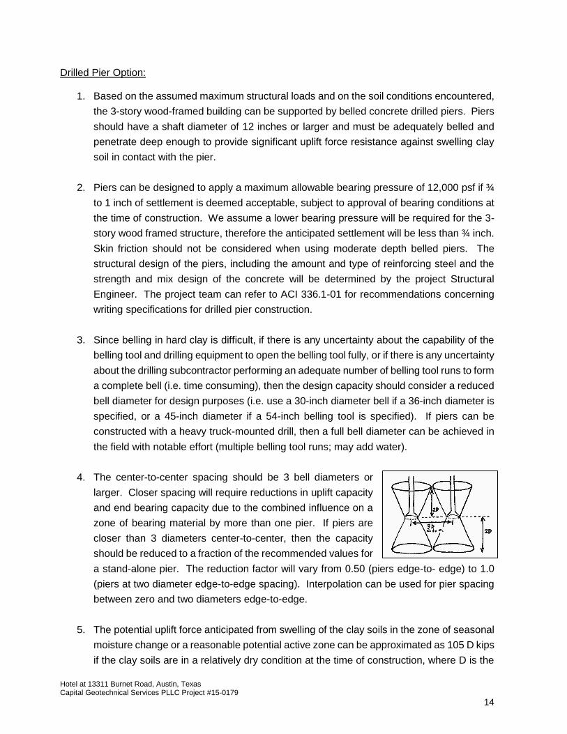
4. The center-to-center spacing should be 3 bell diameters or
larger. Closer spacing will require reductions in uplift capacity
and end bearing capacity due to the combined influence on a
zone of bearing material by more than one pier. If piers are
closer than 3 diameters center-to-center, then the capacity
should be reduced to a fraction of the recommended values for
a stand-alone pier. The reduction factor will vary from 0.50 (piers edge-to- edge) to 1.0
(piers at two diameter edge-to-edge spacing). Interpolation can be used for pier spacing
between zero and two diameters edge-to-edge.
5. The potential uplift force anticipated from swelling of the clay soils in the zone of seasonal
moisture change or a reasonable potential active zone can be approximated as 105 D kips
if the clay soils are in a relatively dry condition at the time of construction, where D is the

Hotel at 13311 Burnet Road, Austin, Texas Capital Geotechnical Services PLLC Project #15-0179
15
diameter of the pier in feet. The depth of the active zone is assumed to be 15 feet. Note
that no factor has been applied to potential uplift force (i.e. no load factor or LFRD design).
Piers should be sufficiently reinforced to resist tensile stresses associated with swelling of
the surrounding clay.
6. The diameter of the bell should be three times the diameter of the straight shaft to resist
uplift forces associated with the swelling of the upper soils and to reduce the risk of caving
during construction of the bells. Uplift resistance is calculated from empirical models and
the contribution to uplift resistance is likely influenced by the weight of the soil above the
bell, the shear strength of the soil above the bell, the dead weight of the pier, and
downward structural axial load (dead load “DL”). Belled piers will provide uplift resistance
against swelling clay and against wind shear loads and the uplift capacity can be estimated
to be:
12” shaft / 36” bell, embedded 21 feet below grade: 78 kips + DL applied at top of pier
12” shaft / 30” as-built bell, embedded 21 feet: 65 kips+ DL applied at top of pier
12” shaft / 36” bell, embedded 22 feet below grade: 94 kips + DL applied at top of pier
12” shaft / 30” as-built bell, embedded 22 feet: 72 kips+ DL applied at top of pier
12” shaft / 36” bell, embedded 23 feet: 105 kips+ DL applied at top of pier
12” shaft / 30” as-built bell, embedded 23 feet: 75 kips+ DL applied at top of pier
18” shaft / 54” bell, embedded 21 feet below grade: 106 kips + DL applied at top of pier
18” shaft / 54” bell, embedded 22 feet below grade: 129 kips + DL applied at top of pier
18” shaft / 45” bell, embedded 22 feet below grade: 109 kips + DL applied at top of pier
18” shaft / 54” bell, embedded 23 feet below grade: 153 kips + DL applied at top of pier
18” shaft / 45” bell, embedded 23 feet below grade: 128 kips + DL applied at top of pier
Note that no factor of safety has been applied to uplift resistance values (i.e. ASD design),
therefore a deeper penetration can be considered.
7. A minimum void of 10 inches should exist beneath the grade level beams between piers
to accommodate future swelling of the clay subgrade soil and prevent the application of
uplift forces on the grade beams and on the piers. The void concentrates the dead loads
onto the piers. The voids can be created using cardboard forms (void boxes). The soils
below the grade beams should be graded to drain away from the piers (grade beam trench
and void space down to middle of trench between piers).
8. A dry method of construction may be adequate to construct open shafts. In the event of
rain or water seepage into the shaft, no more than 5 inches of water should be present at

Hotel at 13311 Burnet Road, Austin, Texas Capital Geotechnical Services PLLC Project #15-0179
16
the bottom of the shaft when concrete placement begins because of the risk of washing
out cement in the bottom portion of the pier. Loose soil or debris should not be present at
the bottom of the shaft when concrete placement begins. Poor cleaning of compressible
cuttings at the bottom can lead to significant settlement.
9. Concrete should be placed the same day the shaft drilling is completed to limit changes in
the shaft bottom and shaft sidewalls that can reduce mobilized capacity and to reduce the
risk of bell cave-in.
10. To reduce the potential for arching within the shaft or casing, Capital Geotechnical
recommends using a concrete mix with a slump of 5 inches to 7 inches. If the concrete
has a slump that is less than or equal to 7 inches, the upper 5 feet of concrete should be
vibrated to assure proper consolidation in that region. If the slump is greater than 7 inches,
the concrete should not be vibrated because of the potential to segregate cement and
aggregates.
11. “Mushroom” tops must not be produced or left in place after the concrete placement.
Heaving of clay soil against protruding concrete (enlarged pier top) can produce notable
uplift force that is not considered in the design of the piers.
12. A tremie pipe can be used to place concrete to prevent segregation of concrete ingredients
and to prevent moving the reinforcing steel cage. A free-fall method might allow the
concrete to strike reinforcing steel, casing, or shaft sidewalls, causing segregation and
undesirable concrete strength properties. A free-fall method is acceptable if the concrete
is directed through a hopper and falls down the center of the shaft without striking the
sides of the shaft or the reinforcing steel cage.
13. The contractor can refer to ACI 336.1-01 for ACI recommendations concerning concrete
pier construction.
14. The performance of the foundation system is highly dependent on the quality of the
installation. Therefore, Capital Geotechnical Services should be retained to document the
drilling conditions encountered, the cleaning of the bottom of the shaft, the type of bearing
material, the depth and diameter of pier, and the size, number, configuration, and grade
of steel reinforcement.
15. Concrete material should be sampled and tested for compressive strength, and placement
operations should be monitored to record concrete slump, temperature, and age at time
of placement. Detailed concrete batch tickets should be provided by the supplier to permit
review and documentation of water-cement ratios and cement content.

Hotel at 13311 Burnet Road, Austin, Texas Capital Geotechnical Services PLLC Project #15-0179
17
16. Horizontal forces (lateral loads) can be resisted by a combination of the soils around the
piers and the stiffness of the piers. Capital Geotechnical Services can assist the Structural
Engineer with lateral load analysis by providing the soil-related design parameter values
if the method of analysis is indicated to us.
17. A sulfate resistant concrete mix should be used due to historically high sulfate
concentrations in the “Del Rio” clay and clay-shale. We recognize that Type 5 cement
may not be readily available. Concrete made with cement that meets ASTM C 150 Type
2 requirements, 25 percent Class F fly ash, and a maximum water-cementitious material
ratio of 0.40 can be used to provide notable resistance. The fly-ash should meet ASTM
C 618 Class F requirements.
18. Belled piers may be difficult to install if infiltrating groundwater is encountered that can
collapse the bell. The installation of the first belled piers must be carefully observed and
if notable groundwater seepage is encountered, each shaft must be continuously
dewatered (pumped) while waiting for the concrete to be placed (i.e. do not allow
groundwater to build up inside shaft notably above lip at base of bell). This may cause a
slowdown in production as concrete delivery may need to be scattered throughout the day.
19. In expansive clay soils, variations in wetting and drying with depth on opposite sides of a
pier will induce changes in bending moments and shear forces in the pier. This condition
should be considered when analyzing the design of a slender pier.
Stiffened Slab Option:
1. The building structure can be supported on a rigid, monolithically-cast, grid-type grade
beam and slab foundation system (foundation slab) if significant soil improvement is
performed. When placed on expansive soils, subgrade improvement must be performed
to reduce potential soil and foundation movement to levels acceptable to the Owner,
Architect, Structural Engineer, and General Contractor.
2. The rigidity of a stiffened slab will limit the effects of differential soil movement caused by
swelling and shrinkage of clay soils and compression of soils due to structural loads.
However, discernible cracking in brittle construction materials may still occur. This type
of slab should be designed with perimeter grade beams and interior stiffening grade
beams adequate to provide sufficient rigidity to the slab element. The foundation slab can
be designed considering an allowable bearing pressure of 2,500 psf across the grade
beam contact area if all grade beams are placed on properly compacted select fill.

Hotel at 13311 Burnet Road, Austin, Texas Capital Geotechnical Services PLLC Project #15-0179
18
3. Perimeter grade beams should extend at least 18 inches below final adjacent exterior
grade and have a minimum width of 10 inches. The grade beam width and depth will be
determined and detailed by the project Structural Engineer. The grade beam details must
specify minimum beam height and minimum beam penetration below exterior grade
(ground surface).
4. Floor coverings (carpet, tile, wood, laminate, vinyl) can be damaged or subject to mold
growth by moisture penetrating the slab, therefore a moisture vapor barrier (i.e. 10 mil
thick geosynthetic geomembrane) should be placed on top of the select fill and properly
sealed to limit the migration of moisture to and through the slab, and to serve as a
separator between the fill (potentially high friction) and concrete slab. The moisture barrier
can be placed after the grade beams are formed. We recommend lapping the sheets of
vapor barrier 12 inches and taping the joints/laps. Since many field crews do not force
membranes down to make continuous contact with the trench walls and bottom to maintain
proper rectangular beam cross section, if a single sheet of geomembrane is placed across
a trench, we recommend cutting the membrane at the bottom of the grade beam trench to
prevent the poured cross section area from being reduced (prevent bridging at bottom
corners), and installing a separate strip of vapor barrier along the bottom to overlap the
cut membrane on either side of the trench.
5. The foundation slab can be post-tensioned or conventionally reinforced. The foundation
slab should be designed using the PTI, WRI, or BRAB soil-related design parameter
values provided in the subsequent paragraphs.
6. Guidelines for the design of a conventionally reinforced foundation slab are provided by
resources such as the Wire Reinforcement Institute (WRI), the International Building Code
(IBC), the International Residential Code (IRC), the 1968 FHA BRAB report, and ACI
360R.
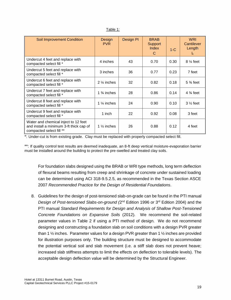
7. We recommend the parameter values in Table 1 when designing a conventionally
reinforced stiffened slab using traditional BRAB or WRI guidelines. We do not recommend
designing and constructing a foundation slab on soil conditions with a design PVR greater
than 1 ½ inches. Parameter values for a design PVR greater than 1 ½ inches are provided
for illustration purposes only or at the exclusive risk of the Owner. The building structure
must be designed to accommodate the potential vertical soil and slab movement (i.e. a
stiff slab does not prevent heave; increased slab stiffness attempts to limit the effects on
deflection to tolerable levels). The acceptable design deflection value will be determined
by the Structural Engineer.
Hotel at 13311 Burnet Road, Austin, Texas Capital Geotechnical Services PLLC Project #15-0179
19
Table 1:
Soil Improvement Condition Design PVR
Design PI BRAB Support Index
C
1-C
WRI Cantilever
Length
lc
Undercut 4 feet and replace with compacted select fill *
4 inches 43 0.70 0.30 8 ¼ feet
Undercut 5 feet and replace with compacted select fill *
3 inches 36 0.77 0.23 7 feet
Undercut 6 feet and replace with compacted select fill *
2 ¼ inches 32 0.82 0.18 5 ¾ feet
Undercut 7 feet and replace with compacted select fill *
1 ¾ inches 28 0.86 0.14 4 ¾ feet
Undercut 8 feet and replace with compacted select fill *
1 ¼ inches 24 0.90 0.10 3 ½ feet
Undercut 9 feet and replace with compacted select fill *
1 inch 22 0.92 0.08 3 feet
Water and chemical inject to 12 feet and install a minimum 3-ft thick cap of compacted select fill **
1 ½ inches 26 0.88 0.12 4 feet
*: Under-cut is from existing grade. Clay must be replaced with properly compacted select fill. **: If quality control test results are deemed inadequate, an 8-ft deep vertical moisture-evaporation barrier must be installed around the building to protect the pre-swelled and treated clay soils.
For foundation slabs designed using the BRAB or WRI type methods, long term deflection
of flexural beams resulting from creep and shrinkage of concrete under sustained loading
can be determined using ACI 318-9.5.2.5, as recommended in the Texas Section ASCE
2007 Recommended Practice for the Design of Residential Foundations.
8. Guidelines for the design of post-tensioned slab-on-grade can be found in the PTI manual
Design of Post-tensioned Slabs-on-ground (2nd Edition 1996 or 3rd Edition 2004) and the
PTI manual Standard Requirements for Design and Analysis of Shallow Post-Tensioned
Concrete Foundations on Expansive Soils (2012). We recommend the soil-related
parameter values in Table 2 if using a PTI method of design. We do not recommend
designing and constructing a foundation slab on soil conditions with a design PVR greater
than 1 ½ inches. Parameter values for a design PVR greater than 1 ½ inches are provided
for illustration purposes only. The building structure must be designed to accommodate
the potential vertical soil and slab movement (i.e. a stiff slab does not prevent heave;
increased slab stiffness attempts to limit the effects on deflection to tolerable levels). The
acceptable design deflection value will be determined by the Structural Engineer.

Hotel at 13311 Burnet Road, Austin, Texas Capital Geotechnical Services PLLC Project #15-0179
20
Table 2
Soil Improvement Condition Design PVR
PTI Differential Movement (ym)
Edge Moisture Variation Distance (em)
Center Lift Edge Lift Center Lift Edge Lift
Undercut 4 feet and replace with compacted select fill *
4 inches 2 ¾ inches 4 inches 5 feet 3 feet
Undercut 5 feet and replace with compacted select fill *
3 inches 2 inches 3 inches 5 feet 3 feet
Undercut 6 feet and replace with compacted select fill *
2 ¼ inches 1 ½ inches 2 ¼ inches 5 feet 3 feet
Undercut 7 feet and replace with compacted select fill *
1 ¾ inches 1 ¼ inches 1 ¾ inches 5 feet 3 feet
Undercut 8 feet and replace with compacted select fill *
1 ¼ inches 1 inch 1 ¼ inches 5 feet 3 feet
Undercut 9 feet and replace with compacted select fill *
1 inch 1 inch 1 inch 5 feet 3 feet
Water and chemical inject to 12 feet and install a minimum 3-ft thick cap of compacted select fill **
1 ½ inches 1 ½ inches 1 inch 5 feet 3 feet
*: Under-cut is from existing grade. Undercut clay must be replaced with properly compacted select fill.
**: If quality control test results are deemed inadequate, an 8-ft deep vertical moisture-evaporation barrier must be installed around the building to protect the pre-swelled and treated clay soils.
The vertical modulus of elasticity (Es) of immediate subgrade under slab for use in
determination of the PTI beta parameter value can be selected to be 125 tsf (1,736 psi).
The PTI partition load slab stress coefficient (Cp) (3rd Edition PTI manual) can be selected
to be 1.10 for ks = 180 pci (compacted select fill).
9. Although the ground-supported foundation slab can be designed for vertical soil
movement greater than 1 inch, the cosmetic elements of the building might not be able to
tolerate the associated slab deflection. The building occupants might perceive excessive
movement when they see cracking in brittle elements such as drywall, hard tile, and
exterior brittle veneer (brick, stucco, stone masonry). The acceptable design slab
deflection must therefore be carefully selected. The foundation slab can be designed for
a PVR greater than 1 inch if an acceptable slab deflection can be achieved by the design.
Potential tilting and angular distortion, however, cannot be avoided, and the effects are
uncertain. The Owner must compare the risks of tilting and associated consequences,
with the costs of more robust soil improvement associated with a lower risk of tilt and
angular distortion.

Hotel at 13311 Burnet Road, Austin, Texas Capital Geotechnical Services PLLC Project #15-0179
21
10. Joints (for contraction and expansion crack control) should be designed and placed in
various portions of the structure (i.e. drywall control joints for long wall spans, above
doorways, in stairway walls, along long ceiling spans, etc). Properly planned placement
of these joints will assist in controlling the degree and location of material cracking that
normally occurs due to soil movements, initial wood shrinkage, expansion and shrinkage
of residential construction materials from changes in humidity and temperature, and strain
in framing from slab tilting, storm wind loads, and storm or man-made vibrations.
11. If the slab will be post-tensioned, the project team may consider requiring that the general
contractor use a subcontractor installer who is PTI certified to help ensure the quality of
the construction.
12. Exposure to the environment may weaken the soils at the grade beam bearing level if the
foundation excavations remain open for an extended duration. Foundation slab concrete
should be placed within 2 weeks of the completion of trench excavations and the moisture
barrier should be installed before any notable rainfall event. If the bearing soils are
softened by surface water intrusion or disturbance, the softened soils must be removed
from the foundation excavation bottom prior to concrete placement.
13. Grade beam dimensions and reinforcing steel should be observed and documented as-
built (“pre-pour” inspection by the Structural Engineer; or by the Geotechnical Engineer if
needed).
14. Prior to installation of reinforcing steel (or tendons) and the moisture-vapor barrier, Capital
Geotechnical Services should be retained to observe and test the grade beam subgrade
to determine if the foundations are being placed on suitable materials and to document
that loose material has been removed. Dynamic Cone Penetrometer (DCP) tests can be
performed to help evaluate subgrade condition. In areas where the subgrade is soft or
loose, the soil should be removed and foundations lowered to bear on firm soil or
foundation subgrade elevations can be restored using flowable fill approved by the
Structural Engineer.
15. Concrete material should be sampled and tested for compressive strength, and placement
operations should be monitored to record concrete slump, temperature, and age at time
of placement. Concrete batch tickets should be provided by the supplier and collected by
the General Contractor to permit inspection and documentation of water-cement ratio,
cement content, and other mix design ingredients.
Hotel at 13311 Burnet Road, Austin, Texas Capital Geotechnical Services PLLC Project #15-0179
22
16. We recommend that a floor flatness survey be performed within 2 weeks after the concrete
is poured to document the initial elevation profile condition of the slab. Such information
will be useful if future soil and slab movement is suspected and must be compared with
the initial elevation differences.
Driven Steel Pipe Piles:
Driven steel pipe piles can be considered in lieu of belled concrete piers to support a
structurally supported concrete slab cast on void boxes. Pipe piles are typically 8-inch outside
diameter elements installed to a depth great enough to provide adequate uplift resistance against
swelling clay soil in contact with the pile. Capital Geotechnical Services can provide an addendum
to this report upon request addressing the design of steel pipe piles if piles will be seriously
considered.
STRUCTURALLY SUPPORTED SLAB (IF USED)
A minimum 10-inch void should be included beneath the uniform thickness portions of the slab
to prevent swelling clay from inducing uplift pressures on the slab and associated piers. A void
space should also be included beneath the grade beams, but a low permeability backfill (clay soil)
must be used along the perimeter of the building in unpaved areas to limit water infiltration and
accumulation in these voids.
If carton forms are used, installation must be performed with care to assure that the void boxes
are not allowed to become wet or crushed before and during concrete placement and finishing
operations. Cardboard forms that have been damaged by rain must be replaced or allowed to
dry and have their capacity verified before placement of concrete. Masonite boards can be
applied on top of the carton forms to reduce the risk of crushing.
Regional carton form suppliers include:
Surevoid: http://www.surevoid.com/company/homepage_tech.php
Savway: http://www.savway.com/products.html
VoidForm Products, Inc.: http://www.voidform.com/CaraCor/
Soil retainer strips (i.e. Motzblock “Sureretainer”) can be used to prevent subsequent soil
backfill from displacing the void box.
Hotel at 13311 Burnet Road, Austin, Texas Capital Geotechnical Services PLLC Project #15-0179
23
To prevent potential tripping hazards, access and entry slabs by doors should be designed
with care since the exterior flatwork might heave with the clay soils. The access and entry slabs
can be structurally supported on drilled piers if the project team does not want any risk of joint
faulting between the doorways and the exterior slabs. Doweling can alternatively be considered
to prevent joint faulting but are prone to cracking the flatwork if differential movement occurs. A
hinged toe-beam detail (over void space) can be used as a transition slab between a pier-
supported structural slab and any adjacent concrete flatwork. Capital Geotechnical Services
should be retained to review construction plans and specifications to review details if a toe-beam
transition element is used.
Based on previous experience, we recommend that roof gutter drain downspouts not be
allowed to discharge near void boxes or within nearby perimeter backfill. As part of the final
punch-list inspection for the project, we recommend including an inspection to verify that roof
drains were properly constructed.
Due to the eventual degradation of the void boxes, a bonding moisture barrier composite with
notable peel adhesion properties should be used (i.e. Barrier-Bac VBC-350 31 mil) as the
moisture barrier in lieu of typical smooth thin geomembrane products.
SEISMIC DESIGN
The subject site is located in a region of low seismicity. The region has relatively low spectral
response acceleration and can be assigned to “Seismic Design Category A” according to ASCE
7-05 and Section 1613 of the 2012 IBC guidelines. The subject site can be categorized as a
“Class D” site for determination of design soil shear wave velocities.
PAVEMENT THICKNESS DESIGN
Estimates of traffic loads and volumes were not provided to Capital Geotechnical. Capital
Geotechnical has therefore assumed a daily traffic volume of 319 vehicle trips per day. This value
was estimated using the ITE (Institute of Transportation Engineers) average trip generation rate
of 4.90 vehicle trips per day per room for an “all suites hotel” land use. We understand there will
be approximately 65 units in the hotel.
Information on planned pavement surface grades was not provided to Capital Geotechnical
Services at the time of this report. We assume minor fill or excavation may be required to reach
planned pavement subgrade elevation across the site. Excavated clay can be re-used as fill
Hotel at 13311 Burnet Road, Austin, Texas Capital Geotechnical Services PLLC Project #15-0179
24
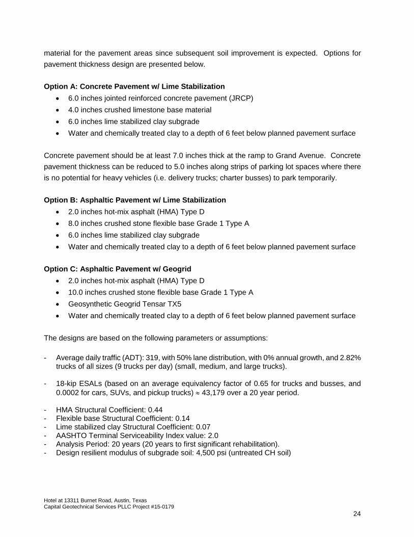
material for the pavement areas since subsequent soil improvement is expected. Options for
pavement thickness design are presented below.
Option A: Concrete Pavement w/ Lime Stabilization
6.0 inches jointed reinforced concrete pavement (JRCP)
4.0 inches crushed limestone base material
6.0 inches lime stabilized clay subgrade
Water and chemically treated clay to a depth of 6 feet below planned pavement surface
Concrete pavement should be at least 7.0 inches thick at the ramp to Grand Avenue. Concrete
pavement thickness can be reduced to 5.0 inches along strips of parking lot spaces where there
is no potential for heavy vehicles (i.e. delivery trucks; charter busses) to park temporarily.
Option B: Asphaltic Pavement w/ Lime Stabilization
2.0 inches hot-mix asphalt (HMA) Type D
8.0 inches crushed stone flexible base Grade 1 Type A
6.0 inches lime stabilized clay subgrade
Water and chemically treated clay to a depth of 6 feet below planned pavement surface
Option C: Asphaltic Pavement w/ Geogrid
2.0 inches hot-mix asphalt (HMA) Type D
10.0 inches crushed stone flexible base Grade 1 Type A
Geosynthetic Geogrid Tensar TX5
Water and chemically treated clay to a depth of 6 feet below planned pavement surface
The designs are based on the following parameters or assumptions:
- Average daily traffic (ADT): 319, with 50% lane distribution, with 0% annual growth, and 2.82%
trucks of all sizes (9 trucks per day) (small, medium, and large trucks).
- 18-kip ESALs (based on an average equivalency factor of 0.65 for trucks and busses, and
0.0002 for cars, SUVs, and pickup trucks) 43,179 over a 20 year period. - HMA Structural Coefficient: 0.44 - Flexible base Structural Coefficient: 0.14 - Lime stabilized clay Structural Coefficient: 0.07 - AASHTO Terminal Serviceability Index value: 2.0 - Analysis Period: 20 years (20 years to first significant rehabilitation). - Design resilient modulus of subgrade soil: 4,500 psi (untreated CH soil)
Hotel at 13311 Burnet Road, Austin, Texas Capital Geotechnical Services PLLC Project #15-0179
25
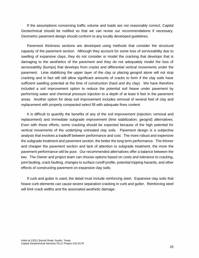
If the assumptions concerning traffic volume and loads are not reasonably correct, Capital
Geotechnical should be notified so that we can revise our recommendations if necessary.
Geometric pavement design should conform to any locally developed guidelines.
Pavement thickness sections are developed using methods that consider the structural
capacity of the pavement section. Although they account for some loss of serviceability due to
swelling of expansive clays, they do not consider or model the cracking that develops that is
damaging to the aesthetics of the pavement and they do not adequately model the loss of
serviceability (bumps) that develops from cracks and differential vertical movements under the
pavement. Lime stabilizing the upper layer of the clay or placing geogrid alone will not stop
cracking and in fact will still allow significant amounts of cracks to form if the clay soils have
sufficient swelling potential at the time of construction (hard and dry clay). We have therefore
included a soil improvement option to reduce the potential soil heave under pavement by
performing water and chemical pressure injection to a depth of at least 6 feet in the pavement
areas. Another option for deep soil improvement includes removal of several feet of clay and
replacement with properly compacted select fill with adequate fines content.
It is difficult to quantify the benefits of any of the soil improvement (injection; removal and
replacement) and immediate subgrade improvement (lime stabilization; geogrid) alternatives.
Even with these efforts, some cracking should be expected because of the high potential for
vertical movements of the underlying untreated clay soils. Pavement design is a subjective
analysis that involves a tradeoff between performance and cost. The more robust and expensive
the subgrade treatment and pavement section, the better the long term performance. The thinner
and cheaper the pavement section and lack of attention to subgrade treatment, the more the
pavement performance will be poor. Our recommended alternatives offer a balance between the
two. The Owner and project team can choose options based on costs and tolerance to cracking,
joint faulting, crack faulting, changes to surface runoff profile, potential tripping hazards, and other
effects of constructing pavement on expansive clay soils.
If curb and gutter is used, the detail must include reinforcing steel. Expansive clay soils that
heave curb elements can cause severe separation cracking in curb and gutter. Reinforcing steel
will limit crack widths and the associated aesthetic damage.
Hotel at 13311 Burnet Road, Austin, Texas Capital Geotechnical Services PLLC Project #15-0179
26
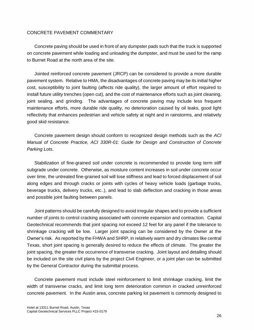
CONCRETE PAVEMENT COMMENTARY
Concrete paving should be used in front of any dumpster pads such that the truck is supported
on concrete pavement while loading and unloading the dumpster, and must be used for the ramp
to Burnet Road at the north area of the site.
Jointed reinforced concrete pavement (JRCP) can be considered to provide a more durable
pavement system. Relative to HMA, the disadvantages of concrete paving may be its initial higher
cost, susceptibility to joint faulting (affects ride quality), the larger amount of effort required to
install future utility trenches (open cut), and the cost of maintenance efforts such as joint cleaning,
joint sealing, and grinding. The advantages of concrete paving may include less frequent
maintenance efforts, more durable ride quality, no deterioration caused by oil leaks, good light
reflectivity that enhances pedestrian and vehicle safety at night and in rainstorms, and relatively
good skid resistance.
Concrete pavement design should conform to recognized design methods such as the ACI
Manual of Concrete Practice, ACI 330R-01: Guide for Design and Construction of Concrete
Parking Lots.
Stabilization of fine-grained soil under concrete is recommended to provide long term stiff
subgrade under concrete. Otherwise, as moisture content increases in soil under concrete occur
over time, the untreated fine-grained soil will lose stiffness and lead to forced displacement of soil
along edges and through cracks or joints with cycles of heavy vehicle loads (garbage trucks,
beverage trucks, delivery trucks, etc..), and lead to slab deflection and cracking in those areas
and possible joint faulting between panels.
Joint patterns should be carefully designed to avoid irregular shapes and to provide a sufficient
number of joints to control cracking associated with concrete expansion and contraction. Capital
Geotechnical recommends that joint spacing not exceed 12 feet for any panel if the tolerance to
shrinkage cracking will be low. Larger joint spacing can be considered by the Owner at the
Owner’s risk. As reported by the FHWA and SHRP, in relatively warm and dry climates like central
Texas, short joint spacing is generally desired to reduce the effects of climate. The greater the
joint spacing, the greater the occurrence of transverse cracking. Joint layout and detailing should
be included on the site civil plans by the project Civil Engineer, or a joint plan can be submitted
by the General Contractor during the submittal process.
Concrete pavement must include steel reinforcement to limit shrinkage cracking, limit the
width of transverse cracks, and limit long term deterioration common in cracked unreinforced
concrete pavement. In the Austin area, concrete parking lot pavement is commonly designed to

Hotel at 13311 Burnet Road, Austin, Texas Capital Geotechnical Services PLLC Project #15-0179
27
have #3 steel reinforcement bars at 18-inch spacing in both directions. Alternatively, the project
team can use the drag formula described in ACI 330R.
Steel reinforcement must ideally be interrupted at the contraction joints (not passed into
adjacent panel) except between perimeter panels and the next row of interior panels where
alternating bars can cross the joint to serve as tie-bars. At other joint locations, if steel is placed
through (under) contraction joints, then the pavement becomes a CRCP (continuously reinforced
concrete pavement) and becomes more susceptible to shrinkage cracking, punchouts, and
spalling. Note that steel reinforcement should have at least 2 inches of cover. Ideally, the
reinforcement should be placed 2 inches below top of pavement (ACI 330R-2.8.1; ACI
325.12R.4.6). If irregular shaped panels (neither square nor rectangular) are planned in some
areas of the parking lot, these panels should be reinforced regardless of the joint spacing.
Construction joints may have to be formed if necessary during construction and should line up
with a planned contraction joint.
Dowels can be used to transfer load between concrete panels, to reduce the chance of joint
faulting, and to limit deflections and damage to panel edges when supporting high volume truck
loads. Minimum 24-inch long, 3/4-inch diameter smooth steel dowels, spaced 18 inches apart
should be placed between panels. Dowels are typically placed in the middle of the vertical
pavement section and must be properly horizontally aligned.
Reinforcement, dowel, and joint details should be in accordance with the American Concrete
Institute (ACI) or Portland Cement Association (PCA) guidelines.
Curb-and-gutter concrete elements must be tied to the concrete pavement using tie-bars
wherever there is a downward slope behind the curbline (i.e. slope to a detention pond). Clay
slopes will creep downhill over time, causing severe separation cracking between the curb and
the concrete pavement unless the two elements are tied together.
PAVEMENT MAINTENANCE
Flexible pavements are generally designed by geotechnical engineers to provide a 20-year
service life before requiring an extensive rehabilitation, and only if proper maintenance is
performed. The actual service life of a pavement until full reconstruction is actually performed by
the Owner, however, is commonly 40 to 60 years. Regular maintenance can help extend the
design 20-year service life.

Hotel at 13311 Burnet Road, Austin, Texas Capital Geotechnical Services PLLC Project #15-0179
28
Depending on the moisture content fluctuations within the subgrade, the flexible pavement
may develop cracks or separations prematurely. Periodic crack sealing, fog seals, and slurry
seals are to be expected and must be performed to maintain the service life and maintain the
quality of the pavement by preventing water from infiltrating into the subgrade and by maintaining
the quality of the surface.
The 20-year service life assumes that the Owner will perform at a minimum an evaluation
every two (2) years and perform crack sealing as necessary. It is also assumed that a thick
asphalt seal coat or “slurry coat” will be placed as needed but at least three times during the 20
year service life.
A primary cause for deterioration of hot mix asphalt pavement is oxidative aging that results
in brittle HMA. Preventative maintenance (crack sealing, fog seals, slurry seals, and chip seals)
will provide a protective seal or rejuvenate the asphalt binder to extend the life of the HMA.
If concrete pavement is used, the Owner should anticipate performing a crack and joint
cleaning and sealing operation at least twice during the first 20 years of service (e.g. every 7
years). Diamond grinding can be considered at 8 to 10 year intervals if pavement smoothness
needs to be restored (re-leveling areas that exhibit joint faulting or other irregularities) and there
are no issues with drainage, inadequate doweling (load transfer), structural integrity, weak
subgrade with an inadequate pavement section design, D-cracking, and reactive aggregates,
since such issues would have to be addressed (repaired) before spending time, money, and effort
on grinding to restore levelness.
PAVEMENT MATERIAL RECOMMENDATIONS AND TESTING
Selection, transportation, placement, and compaction of pavement materials should be
performed in accordance with locally developed guidelines (e.g. City of Austin Standard
Specifications, Series 200 and 300).
Subgrade Preparation
1. Pavement subgrade must be clear of organic matter. Soil improvement should be
performed as recommended in this report.
2. Pavement subgrades that have local depressions resulting from uneven cut grading or
filling or from equipment traffic (ruts) can lead to ponding of water within the flexible base
layer in that area and subsequent premature loss of subgrade support. Forming and
maintaining a subgrade that is level, smooth, and constructed to required grade is

Hotel at 13311 Burnet Road, Austin, Texas Capital Geotechnical Services PLLC Project #15-0179
29
important to produce proper drainage of the base course layer above the less permeable
soil subgrade. The General Contractor and the earthwork or paving subcontractors must
inspect the subgrade for any depressions before placing the first lift of flexible base course.
3. The contractor should have a mix design performed using the actual site soils and the
stabilizing agent (lime, fly ash, cement). Scheduling should allow two weeks for the mix
design (e.g. lime series) to be completed prior to construction.
4. Stabilizing agents (lime, fly ash, cement) must come from the same source as used in the
mix design. If a new source is selected, particularly for lime, a new mix design is required.
5. High calcium quicklime shall conform to the requirements of ASTM C977 and C110.
6. Lime stabilization design and construction should conform to local, state or federal
government guidelines. Examples include:
City of Austin Standard Specifications Series 200 Item 203S;
TxDOT Specification Item 260;
U.S. DOT FHWA Lime in Soil Stabilization, Publication FHWA-HI-93-031.
The basic procedure for lime stabilization is listed below:
1. Spread lime (either hydrated lime slurry or dry quicklime)
2. Slake (add water) if quicklime is used
3. Mix
4. Compact
5. Mellow
6. Remix
7. Final compaction
8. Cure
Water must be applied periodically to keep the moisture content of the treated soil above
optimum. Water is a key ingredient for the chemical reactions and the mixture must not
be allowed to have insufficient water. Stabilization should extend horizontally 1 foot or
more beyond the edge of the curb and gutter.
9. Item 203S of the City of Austin Standard Specifications addresses the construction of lime
stabilized soil. Moisture content of the soil-lime mixture should be between the optimum

Hotel at 13311 Burnet Road, Austin, Texas Capital Geotechnical Services PLLC Project #15-0179
30
moisture content and 4 percentage points above optimum moisture content at the time of
compaction. The moisture content must be maintained until pavement is placed.
10. Inspection of lime stabilized clay (if applicable) should include documentation of
observations of the method of mixing, the uniformity of mixing, time period between lime
application, mixing, and placement, and measurements of relative compaction and
moisture content at the time of compaction. Atterberg limits tests should be performed to
assure that the PI of the lime stabilized mixture is below 20 during the mellowing period.
Phenolphthalein alcohol indicators can be used to determine the depth of subgrade that
was actually treated.
11. Stabilized clay should be left undisturbed to mellow for at least two days after completion
of the scarifying, lime placement, mixing, and sealing operation, or until the PI is reduced
to below 20. Occasional water sprinkling may be required to keep the surface of the lime
stabilized soil damp. Once mellowing is complete a final mixing should be performed
followed by compaction. In-place moisture-density tests should be performed to confirm
proper construction. The compacted stabilized clay should be left undisturbed and allowed
to cure for a minimum of two days or until trucks can be supported without deflecting the
subgrade. The surface should be kept moist during final curing and be kept moist until
placement of the overlying pavement material. Alternatively a bituminous seal coat can
be applied to protect the stabilized material from drying due to evaporation of moisture.
12. Clay stabilized with dry quicklime should be left undisturbed and allowed to cure for a
minimum of four days after the final scarifying and compaction operation has been
completed.
13. Of locally available geogrid we recommend the Tensar TX5 because it is ideally suited to
the desired function of limiting cracking under swelling and shrinkage conditions and
limiting cracking under soft subgrade conditions. A biaxial geogrid or an approximate
equivalent from another manufacturer approved by Capital Geotechnical may also be
considered but must be submitted for approval. Biaxial geogrid should meet the
requirements of TxDOT DMS-6270: Biaxial Geogrid for Environmental Cracking. Geogrid
must be installed per manufacturer requirements. Sheets of geogrid must overlap at least
18 inches because of the lack of restraint associated with the edge of a sheet. Overlaps
of geogrid should be installed with attention being given to which direction the earth
moving equipment will be pushing the overlying soil; i.e. use a shingle type overlap pattern
in one direction to avoid displacing or lifting a geogrid at the overlaps during fill placement.
If construction is performed when the subgrade soils are relatively moist (soft), a geotextile
can be installed to serve as a filter fabric to maintain separation of the finer-grained
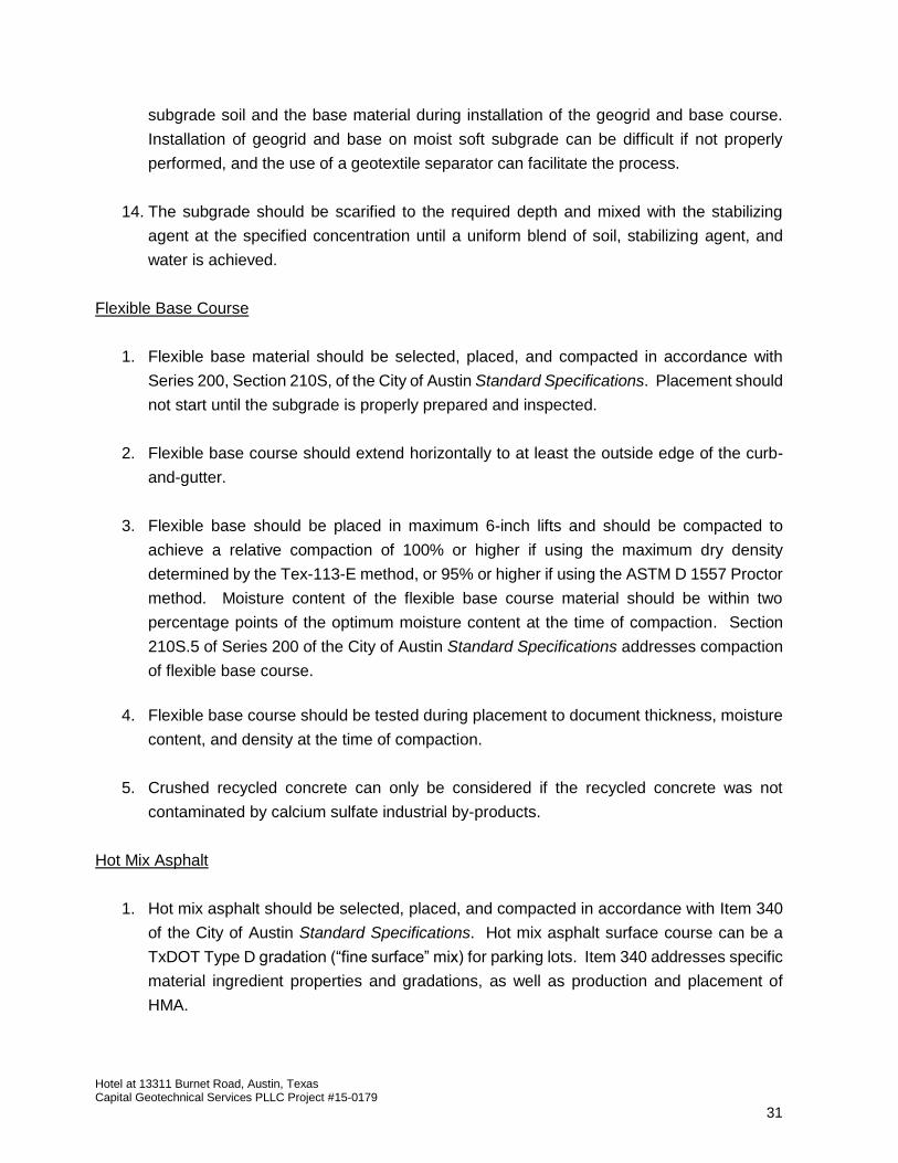
Hotel at 13311 Burnet Road, Austin, Texas Capital Geotechnical Services PLLC Project #15-0179
31
subgrade soil and the base material during installation of the geogrid and base course.
Installation of geogrid and base on moist soft subgrade can be difficult if not properly
performed, and the use of a geotextile separator can facilitate the process.
14. The subgrade should be scarified to the required depth and mixed with the stabilizing
agent at the specified concentration until a uniform blend of soil, stabilizing agent, and
water is achieved.
Flexible Base Course
1. Flexible base material should be selected, placed, and compacted in accordance with
Series 200, Section 210S, of the City of Austin Standard Specifications. Placement should
not start until the subgrade is properly prepared and inspected.
2. Flexible base course should extend horizontally to at least the outside edge of the curb-
and-gutter.
3. Flexible base should be placed in maximum 6-inch lifts and should be compacted to
achieve a relative compaction of 100% or higher if using the maximum dry density
determined by the Tex-113-E method, or 95% or higher if using the ASTM D 1557 Proctor
method. Moisture content of the flexible base course material should be within two
percentage points of the optimum moisture content at the time of compaction. Section
210S.5 of Series 200 of the City of Austin Standard Specifications addresses compaction
of flexible base course.
4. Flexible base course should be tested during placement to document thickness, moisture
content, and density at the time of compaction.
5. Crushed recycled concrete can only be considered if the recycled concrete was not
contaminated by calcium sulfate industrial by-products.
Hot Mix Asphalt
1. Hot mix asphalt should be selected, placed, and compacted in accordance with Item 340
of the City of Austin Standard Specifications. Hot mix asphalt surface course can be a
TxDOT Type D gradation (“fine surface” mix) for parking lots. Item 340 addresses specific
material ingredient properties and gradations, as well as production and placement of
HMA.
Hotel at 13311 Burnet Road, Austin, Texas Capital Geotechnical Services PLLC Project #15-0179
32
2. A prime coat should be applied on the underlying flexible base.
3. HMA paving should only be performed when the air temperature is above 40 degrees
Fahrenheit.
4. Hot mix asphalt should be compacted to achieve a relative compaction between 92% to
96% of maximum theoretical density.
5. Inspection of hot mix asphalt should include placement temperature and thickness during
installation.
6. The surface must be sealed with a finish roller before the mix cools to 1850 F.
Concrete Pavement
The critical factors affecting the performance of concrete pavement are the strength and
quality of the concrete, proper placement of reinforcing steel for crack control, proper jointing for
crack control, and the uniformity of the subgrade.
A. For rigid pavement, concrete mixing, batching, forming, placing, finishing, and curing
should generally conform to the guidelines described in the City of Austin Standard
Specifications Series 300 Item 360: Concrete Pavement. Placement should not start until
the subgrade is properly prepared and inspected.
B. Concrete should consist of a minimum 500 psi flexural strength concrete at 28 day age.
To achieve this flexural strength, a mix with a 28-day compressive strength of 3,500 psi
or 4,000 psi may be required (i.e. do not order 3,000 psi concrete).
C. Curing and protection procedures should be implemented to protect the pavement from
moisture loss, rapid temperature change, and physical disturbance.
D. Concrete should be sampled and field tested by a representative of Capital Geotechnical.
E. Curing protection and procedures must be implemented to protect the concrete from
moisture loss, rapid temperature change, freezing, and physical disturbance.
F. All joints should be properly sealed with a backer rod and approved joint sealant.

Hotel at 13311 Burnet Road, Austin, Texas Capital Geotechnical Services PLLC Project #15-0179
33
SURFACE DRAINAGE, VEGETATION, AND UTILITY CONNECTIONS
Performance of foundation slabs, pavement, and flatwork is influenced by changes in
subgrade moisture conditions. We recommend the following precautions be implemented during
construction:
A. Utility structures that connect to the building should be designed to be flexible enough to
tolerate some differential soil movement. Water supply pipes and sanitary sewer pipes
beneath the slab should be placed in long sections with as few joints (leak-prone) as
possible and should be of durable size and material. Utilities that penetrate the foundation
slab should be designed with either some degree of flexibility or with sleeves in order to
prevent damage or leaking should vertical movement occur (i.e. shower or bathtub drain).
Water supply and sanitary sewer systems should be leak tested after installation.
Telescoping joint or swivel joint pipe fittings can be considered.
If a structurally supported slab is used, water lines should preferably be run above the slab
within the framework. Sanitary sewer lines should preferably be hung in a trench along
the pipe alignment using pipe hangers and wire tied to the horizontal rebar of the slab.
The trench depth must be adequate to maintain the required void space (i.e. 8 inches)
beneath the pipe.
B. The ground surface, pavement, and flatwork around the building should be sloped away
from the building to provide positive drainage away from the building perimeter. A
minimum drop of 6 inches over the first 10 feet from the edge of the foundation is
recommended (IBC 2012: 1804.3).
C. Roof drains should be designed and placed to discharge stormwater at least five feet away
from the building unless pavement abuts the edge of the building at the discharge location.
Roof drain downspouts should also be concentrated on the downslope side of the building.
D. If concrete root barriers are not installed, trees or deep-rooted bushes should not be
planted or allowed to exist adjacent to the building within a distance equal to half of their
mature height because of the root penetration and moisture demand that will dry the
underlying clay soils. Cracks in surrounding pavement or sidewalks should be routinely
sealed to prevent surface water from infiltrating into the subsurface clay soil. Trees should
also not be planted near pavement or flatwork unless a root barrier is installed.
E. Plants placed close to the foundation should be limited to those with low moisture
requirements (do not encourage high rates of irrigation).

Hotel at 13311 Burnet Road, Austin, Texas Capital Geotechnical Services PLLC Project #15-0179
34
F. Air conditioner condensation outlet pipes should preferably on the downslope side of the
building or into a controlled drainage system.
G. If shrubs must be placed adjacent to the building, the landscape beds or planters should
not be recessed (place at grade or elevate above grade and drain properly to prevent
ponding adjacent to the foundation slab).
H. If an exterior sprinkler system is installed to water landscaping, the sprinkler lines should
not be placed within 5 feet of the edge of the foundation. Instead the lines should be
placed so that sprinkler heads with sufficient capacity are used and direct water toward
the structure from 5 feet away.
I. Leak tests should be periodically performed on water supply, sprinkler, and sewer systems
to determine if a leak exists. Any leaking pipes should be repaired as soon as possible to
stop the increase in moisture content in the underlying clay soils. The water supply system
can be easily checked by monitoring the water meter when no water is being used.
J. Landscape islands in parking lot pavement are sources of water infiltration into adjacent
pavement subgrade and base material. Islands should consist of self-contained planters
(geomembrane liner or concrete cutoff elements), or drains should be installed to collect
excess rainwater and discharge to the storm sewer system. Weep holes can be drilled
through the curb to help prevent ponding of water behind the curbline and limit water
infiltration into the subgrade under the pavement.
POST-TENSIONING (IF USED)
Post-tensioning cables (tendons) and accessories need to be accurately placed, protected,
and correctly installed. Utility penetrations through the slab must be planned in conjunction with
the placement of post-tensioning cables. The Structural Engineer, or the Geotechnical Engineer
if needed, should be retained to perform a “pre-pour” inspection to observe and document grade
beam dimensions and proper cable installation.
Pulling (tensioning) of cables should be performed by experienced personnel because of the
danger involved during the pulling and lock-off operation. Cable ends must be properly covered
or coated to prevent corrosion that can allow long term relaxation and reduction of design strength,
and potential excessive movement in isolated areas of the slab. Tendon tails should not be cut
until the tensioning (stressing) test data is approved by the project Structural Engineer. The post-
tensioning stressing operation should be observed by the Structural Engineer (or by the

Hotel at 13311 Burnet Road, Austin, Texas Capital Geotechnical Services PLLC Project #15-0179
35
Geotechnical Engineer if needed) to document proper construction. Observations should include
obtaining a copy of the calibration sheet correlating force and hydraulic pressure of the jack being
used. Each tendon elongation should be measured and compared to specification requirements.
Results can then be provided to the project Structural Engineer for approval.
LIMITATIONS
This report is subject to the limitations and assumptions presented in the report. Should
conditions change or if assumptions are not accurate, we must be contacted to review our
recommendations.
Borings were spaced to obtain a reasonable indication of subsurface conditions. The data
from the borings is only accurate at the exact boring locations. Variations in the subsurface
conditions not indicated by our borings are possible. The recommendations in this report were
developed considering conditions exposed in the exploratory borings and our understanding of
the type of structure planned.
We believe that the geotechnical services for this project were performed with a level of skill
and care ordinarily used by geotechnical engineers practicing in this area at this time. No
warranty, express or implied, is made.
Capital Geotechnical Services should be retained to review plans and specifications related
to geotechnical elements of the construction to check that our recommendations have been
properly interpreted. Capital Geotechnical Services cannot be responsible for incorrect
interpretations of our recommendations, particularly if we are not retained to review plans and
specifications.
This report is valid until site conditions change due to disturbance (cut and fill grading) or
changes to nearby drainage conditions, or for 3 years from the date of this report, whichever
occurs first. Beyond this expiration date, Capital Geotechnical Services shall not accept any
liability associated with the engineering recommendations in the report, particularly if the site
conditions have changed. If this report is desired for use for design purposes beyond this
expiration date, we recommend drilling additional borings so that we can verify the subsurface
condtions and validate the recommendations in this report.
Hotel at 13311 Burnet Road, Austin, Texas Capital Geotechnical Services PLLC Project #15-0179
36
INSPECTIONS
Capital Geotechnical should be retained to perform the field observations, field testing, and
laboratory testing recommended in this report (i.e. City of Austin “Special Inspections”) because
of our familiarity with the project and site conditions. The performance of foundations and
pavement is primarily controlled by the quality of the construction. To prevent misinterpretation
of our recommendations, and to document proper construction, Capital Geotechnical should be
retained to perform quality control (QC) testing, inspection, and documentation during earthwork
and during construction of the foundations and pavement. Quality control (QC) inspections by
Capital Geotechnical Services can include (as applicable depending on design):
Sampling and lab testing of proposed fill material to check and document
classification.
Inspection of soil improvement excavation or soil improvement injection operation.
Testing of compacted fill, pavement base material, or lime stabilized clay subgrade
in-place to check and document proper compaction and moisture-conditioning.
Inspection and documentation of drilled shaft construction.
Pre-pour inspection to check and document grade beam dimensions, void box
installation (if applicable), reinforcing steel installation, and moisture vapor barrier
installation (if not performed by Structural Engineer).
Pre-pour inspection of post-tension cable installation (if not performed by Structural
Engineer).
Concrete sampling and testing to document as-built condition of wet concrete and to
document that the supplier provided an adquate mixture to the site.
Post-tension cable stressing inspection (if not performed by Structural Engineer).
Pre-pour inspection of concrete pavement contruction (reinforcing steel, joint layout,
joint doweling, thickness).
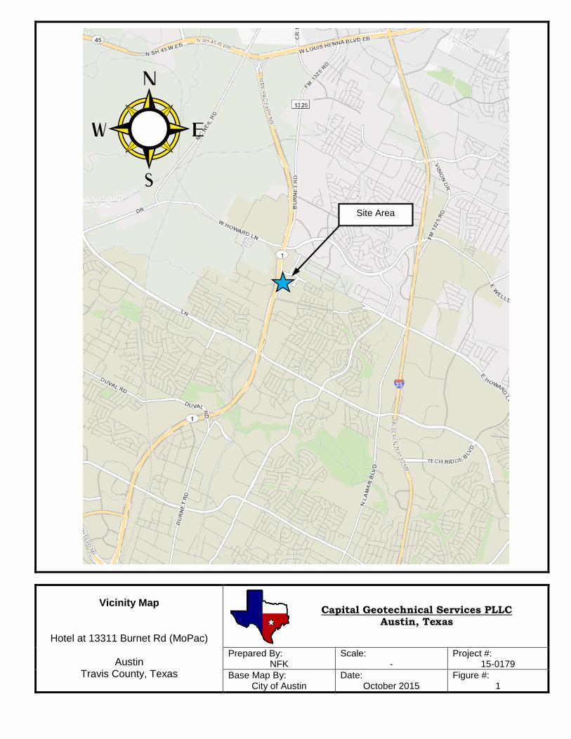
Vicinity Map
Hotel at 13311 Burnet Rd (MoPac)
Austin Travis County, Texas
Prepared By: NFK
Scale: -
Project #: 15-0179
Base Map By: City of Austin
Date: October 2015
Figure #: 1
Capital Geotechnical Services PLLC Austin, Texas
Site Area
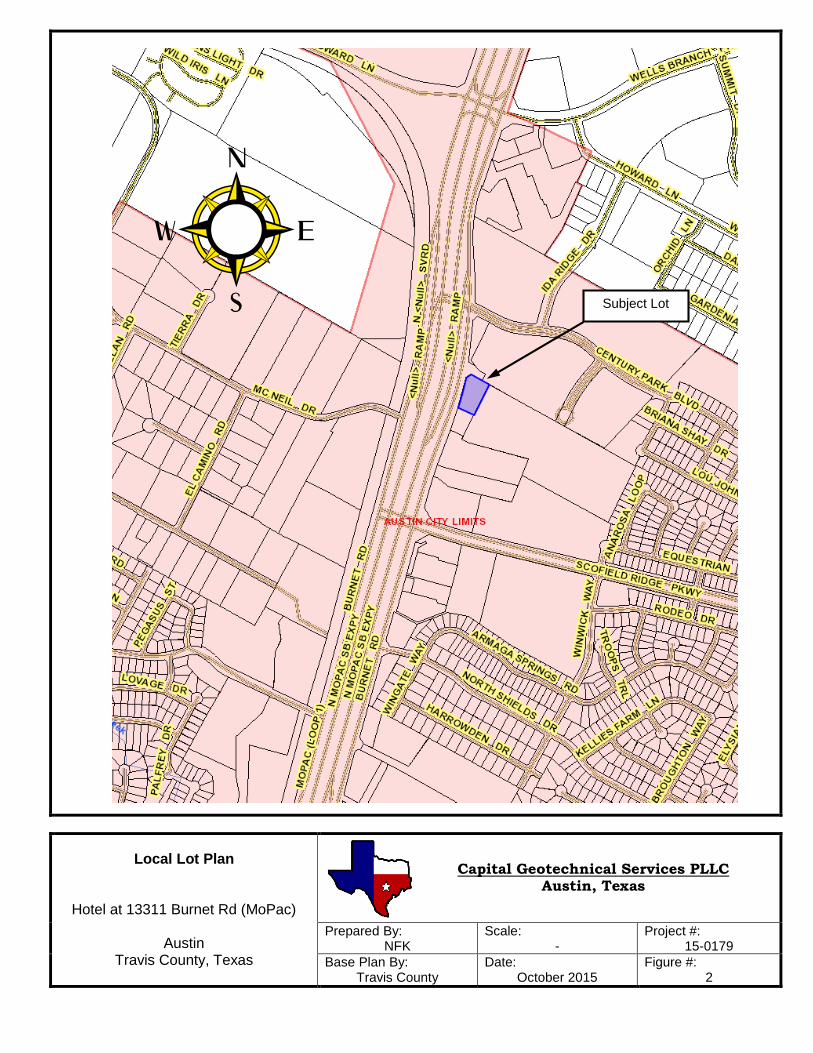
Local Lot Plan
Hotel at 13311 Burnet Rd (MoPac)
Austin Travis County, Texas
Prepared By: NFK
Scale: -
Project #: 15-0179
Base Plan By: Travis County
Date: October 2015
Figure #: 2
Capital Geotechnical Services PLLC Austin, Texas
Subject Lot

Geology Map
Hotel at 13311 Burnet Rd (MoPac)
Austin Travis County, Texas
Prepared By: NFK
Scale: -
Project #: 15-0179
Base Map By: U.T. Bureau of Econ. G.
Date: October 2015
Figure #: 3
Capital Geotechnical Services PLLC Austin, Texas
Site Area
“Kdr”: Clay sedimentary deposit categorized as the “Del Rio Clay” geologic formation. “Kgt”: Limestone rock and marly limestone sedimentary deposit categorized as the “Georgetown Limestone” geologic formation.
Old Burnet Rd (now under MoPac mainlaines)
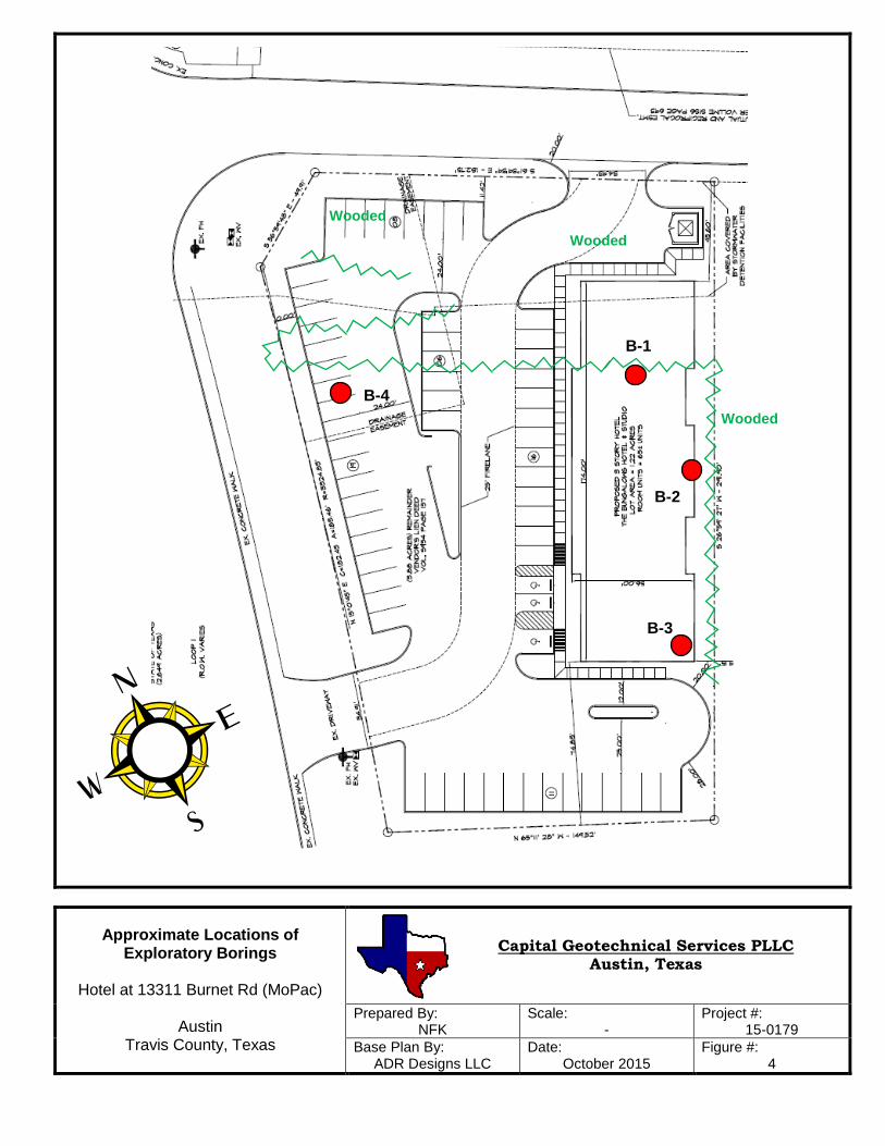
Approximate Locations of Exploratory Borings
Hotel at 13311 Burnet Rd (MoPac)
Austin
Travis County, Texas
Prepared By: NFK
Scale: -
Project #: 15-0179
Base Plan By: ADR Designs LLC
Date: October 2015
Figure #: 4
Capital Geotechnical Services PLLC Austin, Texas
Wooded
Wooded
Wooded
B-1
B-4
B-2
B-3
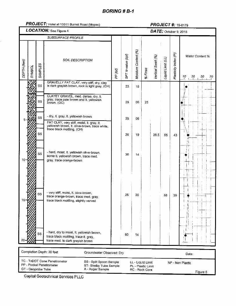


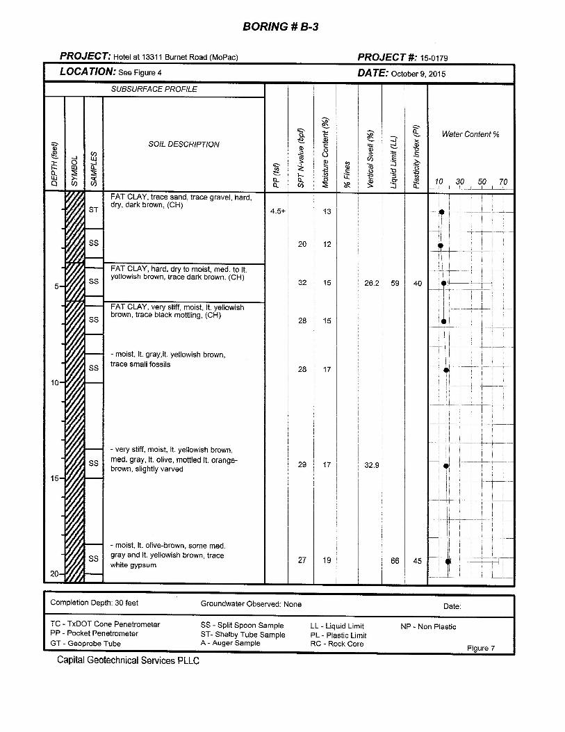


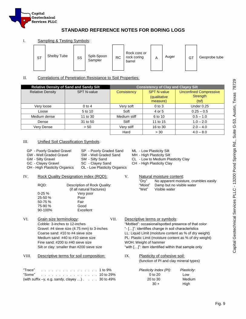
STANDARD REFERENCE NOTES FOR BORING LOGS I. Sampling & Testing Symbols:
II. Correlations of Penetration Resistance to Soil Properties:
Relative Density of Sand and Sandy Silt Consistency of Clay and Clayey Silt
Relative Density SPT N-value Consistency SPT N-value
(qualitative measure)
Unconfined Compressive Strength
(tsf)
Very loose 0 to 4 Very soft 0 to 3 Under 0.25
Loose 5 to 10 Soft 4 or 5 0.25 – 0.5
Medium dense 11 to 30 Medium stiff 6 to 10 0.5 – 1.0
Dense 31 to 50 Stiff 11 to 15 1.0 – 2.0
Very Dense > 50 Very stiff 16 to 30 2.0 – 4.0
Hard > 30 4.0 – 8.0
III. Unified Soil Classification Symbols:
GP - Poorly Graded Gravel SP - Poorly Graded Sand ML - Low Plasticity Silt GW - Well Graded Gravel SW - Well Graded Sand MH - High Plasticity Silt GM - Silty Gravel SM - Silty Sand CL - Low to Medium Plasticity Clay GC - Clayey Gravel SC - Clayey Sand CH - High Plasticity Clay OH - High Plasticity Organics OL - Low Plasticity Organics
IV. Rock Quality Designation index (RQD): V. Natural moisture content: “Dry” No apparent moisture, crumbles easily
RQD: Description of Rock Quality: “Moist” Damp but no visible water (if all natural fractures) “Wet” Visible water 0-25 % Very poor 25-50 % Poor 50-75 % Fair 75-90 % Good 90-100% Excellent
VI. Grain size terminology: VII. Descriptive terms or symbols:
Cobble: 3-inches to 12-inches “Mottled”: occasional/spotted presence of that color
Gravel: #4 sieve size (4.75 mm) to 3-inches “- […]”: identifies change in soil characteristics
Coarse sand: #10 to #4 sieve size LL: Liquid Limit (moisture content as % of dry weight)
Medium sand: #40 to #10 sieve size PL: Plastic Limit (moisture content as % of dry weight)
Fine sand: #200 to #40 sieve size WOH: Weight of hammer
Silt or clay: smaller than #200 sieve size “with […]”: item identified within that sample only
VIII. Descriptive terms for soil composition: IX. Plasticity of cohesive soil:
(function of PI and clay mineral types)
“Trace” . . . . . . . . . . . . . . . . 1 to 9% Plasticity Index (PI): Plasticity:
“Some” . . . . . . . . . . . . . . . . 10 to 29% 0 to 20 Low
(with suffix –y, e.g. sandy, clayey …) . . . . 30 to 49% 20 to 30 Medium
30 + High
Capital G
eote
chn
ical S
erv
ices P
LLC
- 1
32
00 P
ond S
prings R
d.,
Suite G
-53,
Austin,
Texas 7
872
9
Fig. 9
Shelby Tube Split-Spoon Sampler
Rock core or rock coring barrel
Geoprobe tube
Auger
ST
SS
RC
A
GT
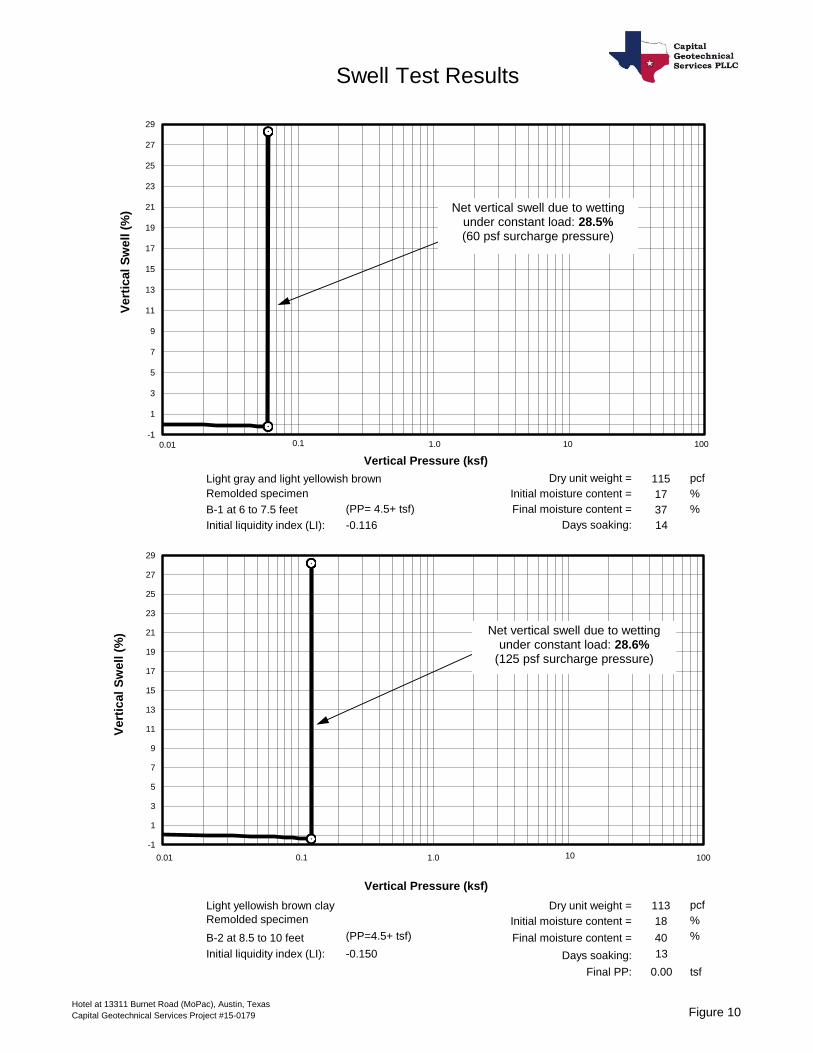
Light gray and light yellowish brown Dry unit weight = 115 pcf
Remolded specimen Initial moisture content = 17 %
B-1 at 6 to 7.5 feet (PP= 4.5+ tsf) Final moisture content = 37 %
Initial liquidity index (LI): Days soaking: 14
Light yellowish brown clay Dry unit weight = 113 pcf
Remolded specimen Initial moisture content = 18 %
B-2 at 8.5 to 10 feet (PP=4.5+ tsf) Final moisture content = 40 %
Initial liquidity index (LI): Days soaking: 13
Final PP: 0.00 tsf
-0.116
-0.150
-1
1
3
5
7
9
11
13
15
17
19
21
23
25
27
29
-1
1
3
5
7
9
11
13
15
17
19
21
23
25
27
29
Vertical Pressure (ksf)
Vertical Pressure (ksf)
0.01 1.0 10 100
0.01 1.0 10 100
Vert
ical
Sw
ell (
%)
Swell Test Results
Vert
ical
Sw
ell (
%) Net vertical swell due to wetting
under constant load: 28.6%(125 psf surcharge pressure)
Net vertical swell due to wetting under constant load: 28.5%(60 psf surcharge pressure)
0.1
0.1
Hotel at 13311 Burnet Road (MoPac), Austin, Texas
Capital Geotechnical Services Project #15-0179 Figure 10

Medium to light yellowish brown Dry unit weight = 124 pcf
Remolded specimen Initial moisture content = 14 %
B-3 at 4 to 5.5 feet (PP= 4.5+ tsf) Final moisture content = 39 %
Initial liquidity index (LI): Days soaking: 14
Lt yellowish brown and lt olive Dry unit weight = 113 pcf
Remolded specimen Initial moisture content = 18 %
B-3 at 13.5 to 15 feet (PP=4.5+ tsf) Final moisture content = 41 %
Initial liquidity index (LI): Days soaking: 13
Final PP: 0.00 tsf
-0.125
-0.067
-1
1
3
5
7
9
11
13
15
17
19
21
23
25
27
29
-1
1
3
5
7
9
11
13
15
17
19
21
23
25
27
29
31
33
Vertical Pressure (ksf)
Vertical Pressure (ksf)
0.01 1.0 10 100
0.01 1.0 10 100
Vert
ical
Sw
ell (
%)
Swell Test Results
Vert
ical
Sw
ell (
%) Net vertical swell due to wetting
under constant load: 32.9%(60 psf surcharge pressure)
Net vertical swell due to wetting under constant load: 26.2%(60 psf surcharge pressure)
0.1
0.1
Hotel at 13311 Burnet Road (MoPac), Austin, Texas
Capital Geotechnical Services Project #15-0179 Figure 11

Related Documents


