Substation Estimator DataBase Basics Section Page Introduction 1 Standard Symbology 3 Forms Main Menu 5 Edit Default Design Voltages 6 Edit Default Wind Zones 7 Edit Default Structures 7 Edit Default Structure Bill of Material (B.O.M.) 8 Edit Default Foundations 11 Project List Main Menu 14 Project Data Main Form 16 Add a New Structure to Project List 16 Delete Existing Stucture from Project List 18 Edit Steel Shape Data (Bill of Material Standard Steel Shapes) 19 Reports Default Structures 21 Default Foundations 22 Default Structures & Fdn’s 23 Project Data 24 Appendix A - Database Setup Instructions

Welcome message from author
This document is posted to help you gain knowledge. Please leave a comment to let me know what you think about it! Share it to your friends and learn new things together.
Transcript
Substation Estimator
DataBase Basics
Section Page
Introduction 1 Standard Symbology 3 Forms Main Menu 5 Edit Default Design Voltages 6 Edit Default Wind Zones 7 Edit Default Structures 7 Edit Default Structure Bill of Material (B.O.M.) 8 Edit Default Foundations 11 Project List Main Menu 14 Project Data Main Form 16 Add a New Structure to Project List 16 Delete Existing Stucture from Project List 18 Edit Steel Shape Data (Bill of Material Standard Steel Shapes) 19 Reports Default Structures 21 Default Foundations 22 Default Structures & Fdn’s 23 Project Data 24 Appendix A - Database Setup Instructions
1
Introduction
The Estimator DataBase was developed strictly using the MicroSoft Access Database program. It has been divided into four modules to facilitate simultaneous access by multiple users, to promote and protect data integrity as well as to limit access by each user to only the data necessary to complete their work:
Module # 1 - Main Database Forms/Reports Module to be used by the designated Database Administrator to maintain the base data compiled in Module # 3. Through this set of forms and reports the Database Administrator also has access directly to the project data (Module # 4) compiled by individual users as an estimating tool for new substation and/or substation modification projects.
Module # 2 - Satellite Database Forms/Reports Module to be used by each design engineer to compile substation structure construction quantities as a means of developing project cost estimates. The design engineer inputs the number and type of each structure along with the proposed type of foundation, and the program automatically extracts the appropriate construction data (drawing numbers, black weight and cubic yards of concrete) from the base data stored in Module #3, compiles the data and stores the project related data in Module # 4.
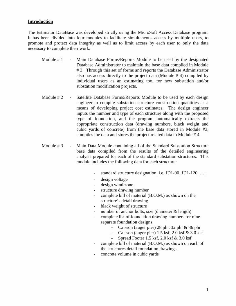
Module # 3 - Main Data Module containing all of the Standard Substation Structure base data compiled from the results of the detailed engineering analysis prepared for each of the standard substation structures. This module includes the following data for each structure:
- standard structure designation, i.e. JD1-90, JD1-120, ….. - design voltage - design wind zone - structure drawing number - complete bill of material (B.O.M.) as shown on the
structure’s detail drawing - black weight of structure - number of anchor bolts, size (diameter & length) - complete list of foundation drawing numbers for nine
separate foundation designs - Caisson (auger pier) 28 phi, 32 phi & 36 phi - Caisson (auger pier) 1.5 ksf, 2.0 ksf & 3.0 ksf - Spread Footer 1.5 ksf, 2.0 ksf & 3.0 ksf
- complete bill of material (B.O.M.) as shown on each of the structures detail foundation drawings.
- concrete volume in cubic yards
2
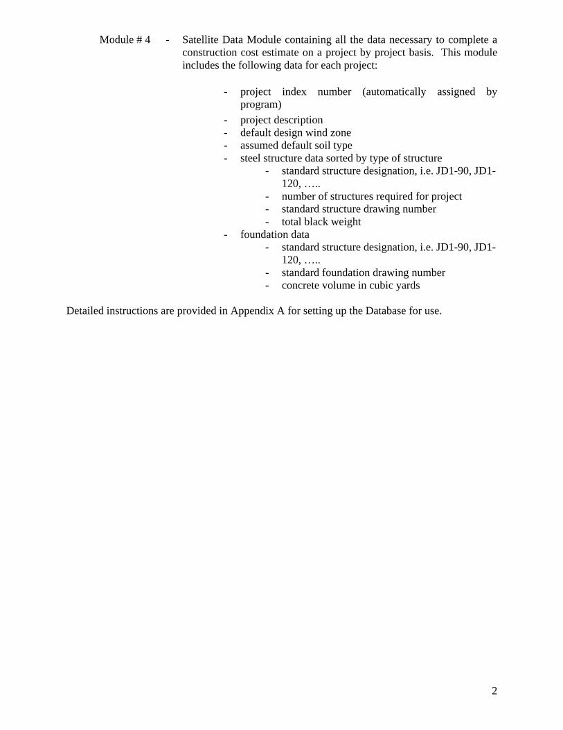
Module # 4 - Satellite Data Module containing all the data necessary to complete a construction cost estimate on a project by project basis. This module includes the following data for each project:
- project index number (automatically assigned by program)
- project description - default design wind zone - assumed default soil type - steel structure data sorted by type of structure
- standard structure designation, i.e. JD1-90, JD1-120, …..
- number of structures required for project - standard structure drawing number - total black weight
- foundation data - standard structure designation, i.e. JD1-90, JD1-
120, ….. - standard foundation drawing number - concrete volume in cubic yards Detailed instructions are provided in Appendix A for setting up the Database for use.
3
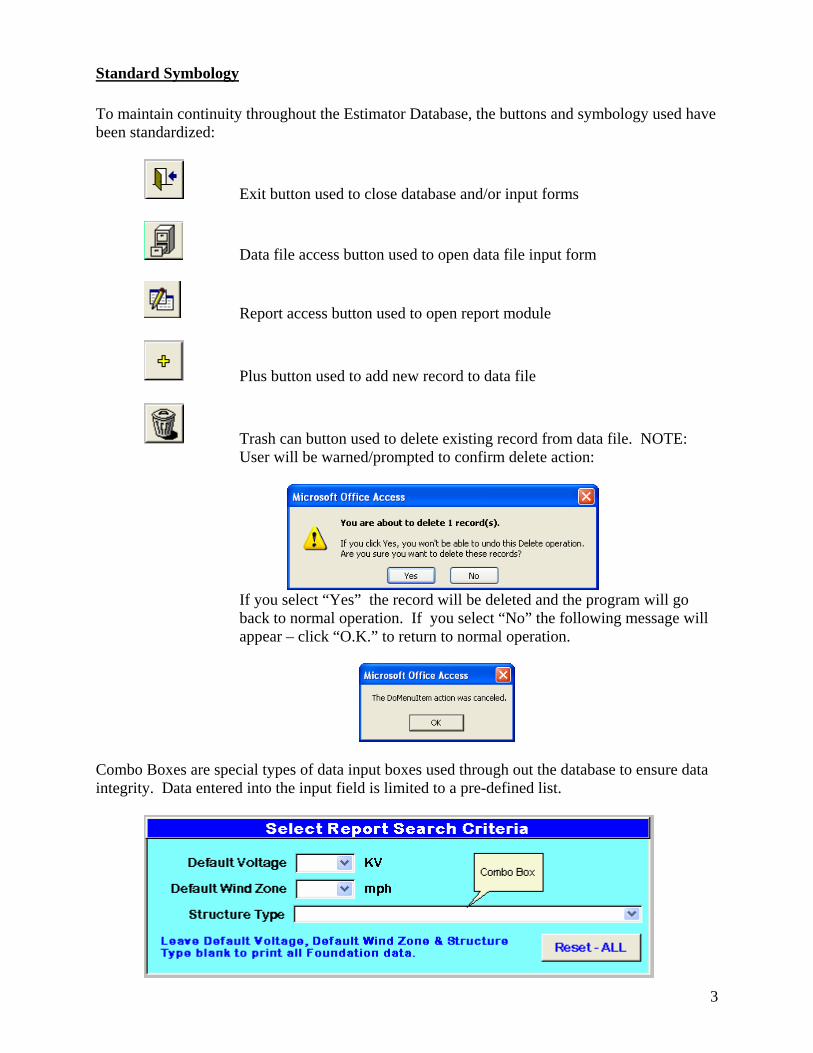
Standard Symbology To maintain continuity throughout the Estimator Database, the buttons and symbology used have been standardized:
Exit button used to close database and/or input forms
Data file access button used to open data file input form
Report access button used to open report module
Plus button used to add new record to data file
Trash can button used to delete existing record from data file. NOTE: User will be warned/prompted to confirm delete action:
If you select “Yes” the record will be deleted and the program will go
back to normal operation. If you select “No” the following message will appear – click “O.K.” to return to normal operation.
Combo Boxes are special types of data input boxes used through out the database to ensure data integrity. Data entered into the input field is limited to a pre-defined list.
4
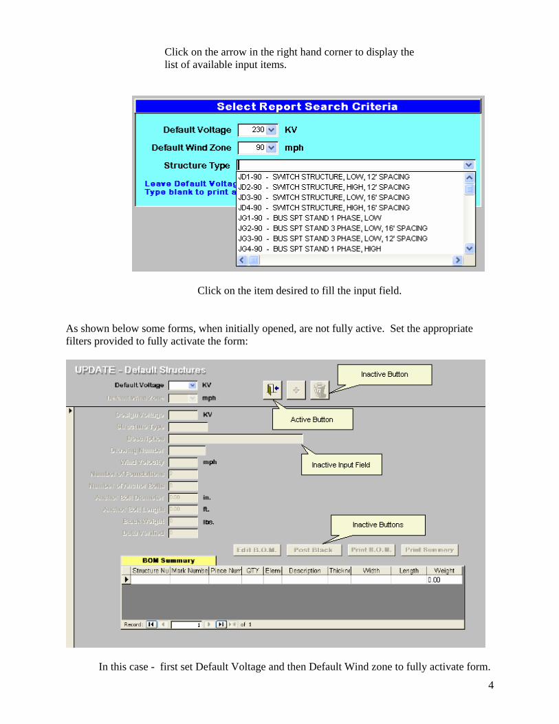
Click on the arrow in the right hand corner to display the
list of available input items.
Click on the item desired to fill the input field. As shown below some forms, when initially opened, are not fully active. Set the appropriate filters provided to fully activate the form:
In this case - first set Default Voltage and then Default Wind zone to fully activate form.
5
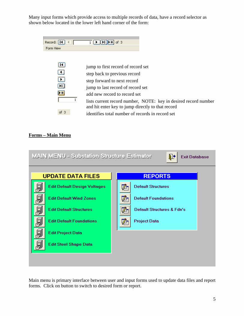
Many input forms which provide access to multiple records of data, have a record selector as shown below located in the lower left hand corner of the form:
jump to first record of record set step back to previous record step forward to next record jump to last record of record set add new record to record set lists current record number, NOTE: key in desired record number
and hit enter key to jump directly to that record identifies total number of records in record set
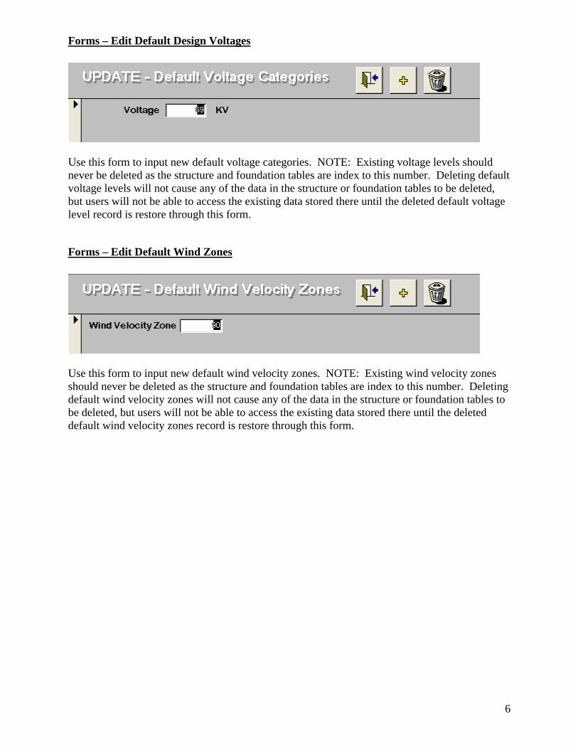
Forms – Main Menu
Main menu is primary interface between user and input forms used to update data files and report forms. Click on button to switch to desired form or report.
6
Forms – Edit Default Design Voltages
Use this form to input new default voltage categories. NOTE: Existing voltage levels should never be deleted as the structure and foundation tables are index to this number. Deleting default voltage levels will not cause any of the data in the structure or foundation tables to be deleted, but users will not be able to access the existing data stored there until the deleted default voltage level record is restore through this form.
Forms – Edit Default Wind Zones
Use this form to input new default wind velocity zones. NOTE: Existing wind velocity zones should never be deleted as the structure and foundation tables are index to this number. Deleting default wind velocity zones will not cause any of the data in the structure or foundation tables to be deleted, but users will not be able to access the existing data stored there until the deleted default wind velocity zones record is restore through this form.
7
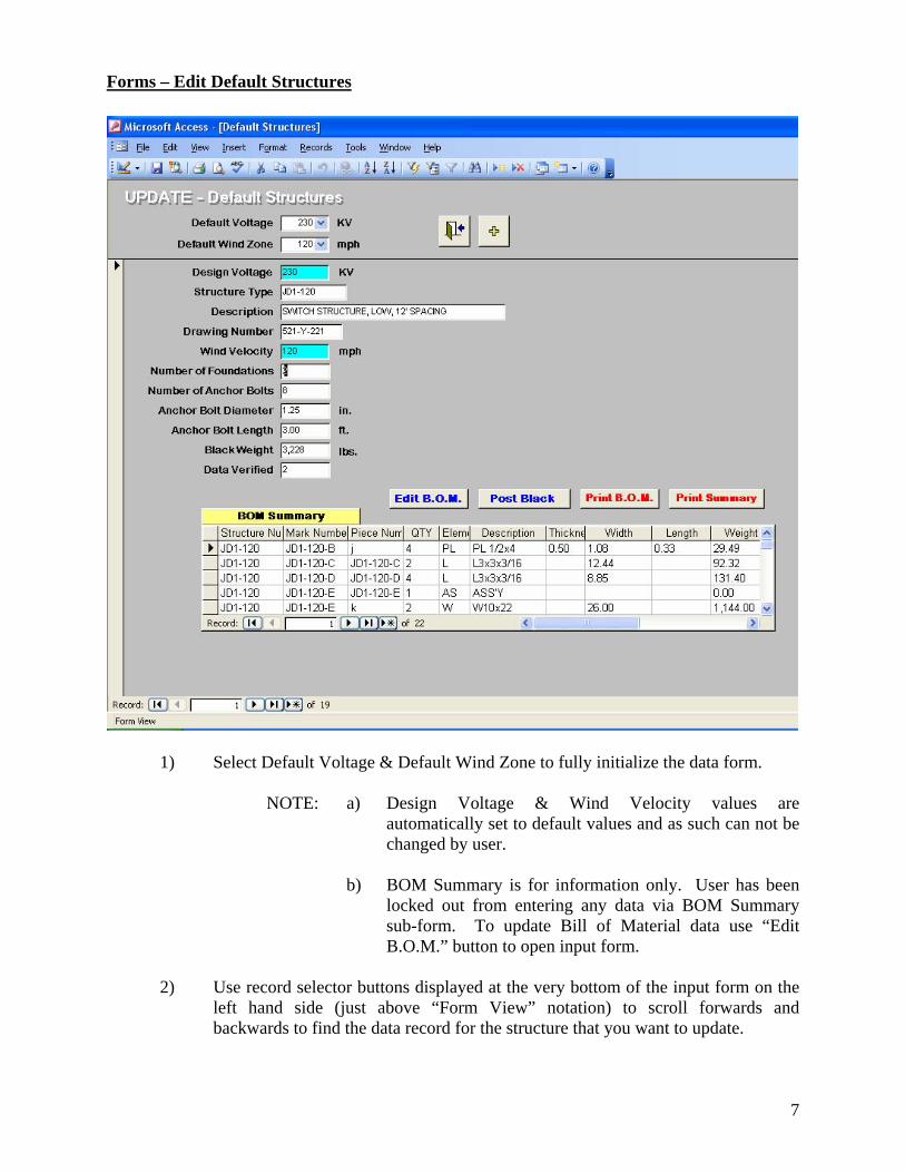
Forms – Edit Default Structures
1) Select Default Voltage & Default Wind Zone to fully initialize the data form. NOTE: a) Design Voltage & Wind Velocity values are
automatically set to default values and as such can not be changed by user.
b) BOM Summary is for information only. User has been
locked out from entering any data via BOM Summary sub-form. To update Bill of Material data use “Edit B.O.M.” button to open input form.
2) Use record selector buttons displayed at the very bottom of the input form on the
left hand side (just above “Form View” notation) to scroll forwards and backwards to find the data record for the structure that you want to update.
8
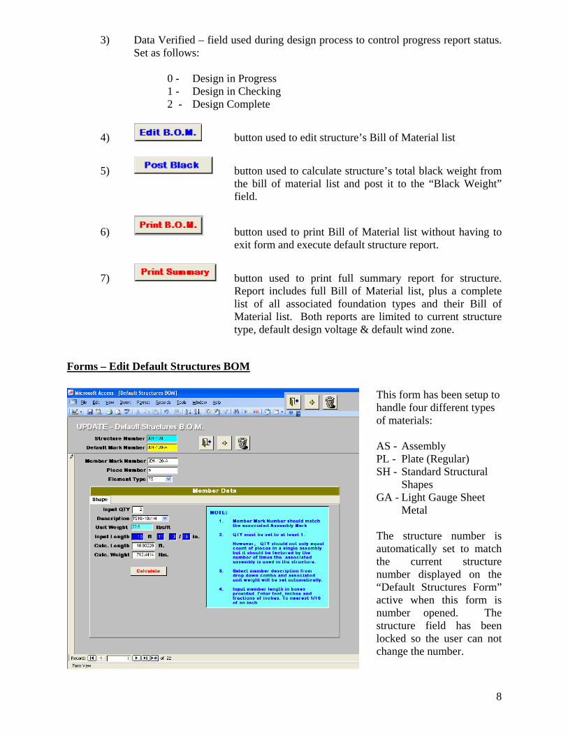
3) Data Verified – field used during design process to control progress report status. Set as follows:
0 - Design in Progress 1 - Design in Checking 2 - Design Complete
4) button used to edit structure’s Bill of Material list
5) button used to calculate structure’s total black weight from the bill of material list and post it to the “Black Weight” field.
6) button used to print Bill of Material list without having to exit form and execute default structure report.
7) button used to print full summary report for structure. Report includes full Bill of Material list, plus a complete list of all associated foundation types and their Bill of Material list. Both reports are limited to current structure type, default design voltage & default wind zone.
Forms – Edit Default Structures BOM
This form has been setup to handle four different types of materials: AS - Assembly PL - Plate (Regular) SH - Standard Structural
Shapes GA - Light Gauge Sheet
Metal The structure number is automatically set to match the current structure number displayed on the “Default Structures Form” active when this form is number opened. The structure field has been locked so the user can not change the number.
9
The “Default Mark Number” field is not bound to the data table, i.e. it is used for reference only. The data in it is not saved in the data table. It controls the value shown in the “Member Mark Number” field. When a new record is added, the “Member Mark Number” is automatically set to match the “Default Mark Number” so that the user can easily add multiple records without having to re-enter the “Member Mark Number” each time. Use the record selector buttons to step forwards or backwards through the list of material items to find the one that you want to edit. Each material type has its own “Member Data” Sub form to facilitate data entry. When the user selects the element type from the “Element Type” combo box the appropriate “Member Data” sub-form is automatically loaded.
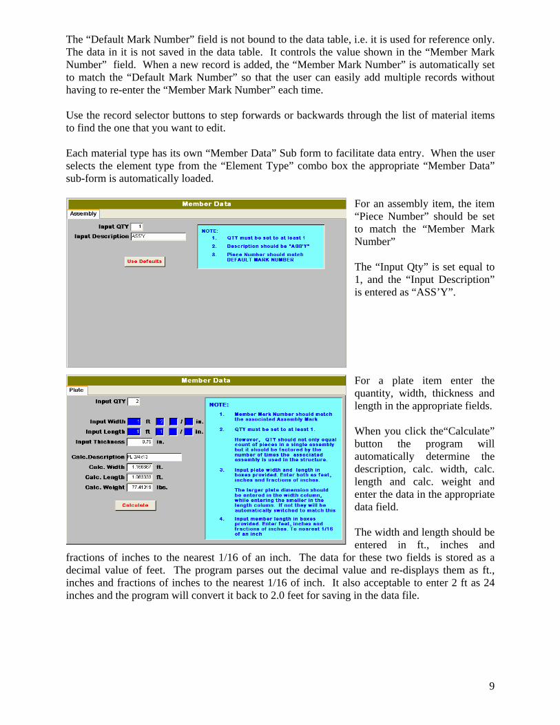
For an assembly item, the item “Piece Number” should be set to match the “Member Mark Number” The “Input Qty” is set equal to 1, and the “Input Description” is entered as “ASS’Y”. For a plate item enter the quantity, width, thickness and length in the appropriate fields. When you click the“Calculate” button the program will automatically determine the description, calc. width, calc. length and calc. weight and enter the data in the appropriate data field. The width and length should be entered in ft., inches and
fractions of inches to the nearest 1/16 of an inch. The data for these two fields is stored as a decimal value of feet. The program parses out the decimal value and re-displays them as ft., inches and fractions of inches to the nearest 1/16 of inch. It also acceptable to enter 2 ft as 24 inches and the program will convert it back to 2.0 feet for saving in the data file.
10
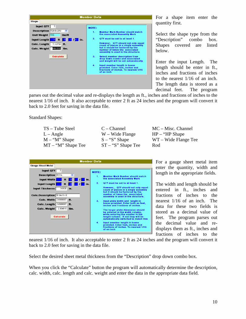
For a shape item enter the quantity first. Select the shape type from the “Description” combo box. Shapes covered are listed below. Enter the input Length. The length should be enter in ft., inches and fractions of inches to the nearest 1/16 of an inch. The length data is stored as a decimal feet. The program
parses out the decimal value and re-displays the length as ft., inches and fractions of inches to the nearest 1/16 of inch. It also acceptable to enter 2 ft as 24 inches and the program will convert it back to 2.0 feet for saving in the data file. Standard Shapes: TS – Tube Steel C – Channel MC – Misc. Channel L – Angle W – Wide Flange HP – “HP Shape M – “M” Shape S – “S” Shape WT – Wide Flange Tee MT – “M” Shape Tee ST – “S” Shape Tee Rod
For a gauge sheet metal item enter the quantity, width and length in the appropriate fields. The width and length should be entered in ft., inches and fractions of inches to the nearest 1/16 of an inch. The data for these two fields is stored as a decimal value of feet. The program parses out the decimal value and re-displays them as ft., inches and fractions of inches to the
nearest 1/16 of inch. It also acceptable to enter 2 ft as 24 inches and the program will convert it back to 2.0 feet for saving in the data file. Select the desired sheet metal thickness from the “Description” drop down combo box.
When you click the “Calculate” button the program will automatically determine the description, calc. width, calc. length and calc. weight and enter the data in the appropriate data field.
11
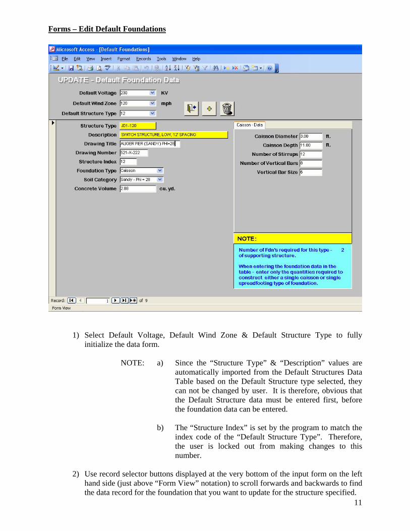
Forms – Edit Default Foundations
1) Select Default Voltage, Default Wind Zone & Default Structure Type to fully initialize the data form.
NOTE: a) Since the “Structure Type” & “Description” values are
automatically imported from the Default Structures Data Table based on the Default Structure type selected, they can not be changed by user. It is therefore, obvious that the Default Structure data must be entered first, before the foundation data can be entered.
b) The “Structure Index” is set by the program to match the
index code of the “Default Structure Type”. Therefore, the user is locked out from making changes to this number.
2) Use record selector buttons displayed at the very bottom of the input form on the left
hand side (just above “Form View” notation) to scroll forwards and backwards to find the data record for the foundation that you want to update for the structure specified.
12
3) Enter the desired “Foundation Type” using the pop down combo box provided. Two
types are available – caisson or spread footer.
4) Enter the desired “Soil Category” using the pop down combo box provided. The available soil categories are pre-set based on the type of foundation selected in item 3 above. The types allowed are as follows:
- Caisson (sandy soil) 28 phi, 32 phi & 36 phi - Caisson (clay soil) 1.5 ksf, 2.0 ksf & 3.0 ksf - Spread footer 1.5 ksf, 2.0 ksf & 3.0 ksf
5) Skip the “Concrete Volume” field for now. That data will be filled in automatically
as you complete the “Caisson – Data” table or “Spread Footer – Data” table as shown in items 6 or 7 respectively.
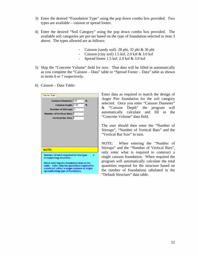
6) Caisson – Data Table:
Enter data as required to match the design of Auger Pier foundation for the soil category selected. Once you enter “Caisson Diameter” & “Caisson Depth” the program will automatically calculate and fill in the “Concrete Volume” data field.
The user should then enter the “Number of Stirrups”, “Number of Vertical Bars” and the “Vertical Bar Size” in turn.
NOTE: When entering the “Number of Stirrups” and the “Number of Vertical Bars”, only enter what is required to construct a single caisson foundation. When required the program will automatically calculate the total quantities required for the structure based on the number of foundations tabulated in the “Default Structure” data table.
13
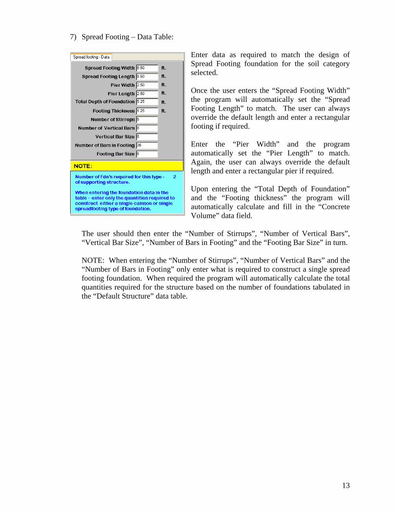
7) Spread Footing – Data Table:
Enter data as required to match the design of Spread Footing foundation for the soil category selected.
Once the user enters the “Spread Footing Width” the program will automatically set the “Spread Footing Length” to match. The user can always override the default length and enter a rectangular footing if required.
Enter the “Pier Width” and the program automatically set the “Pier Length” to match. Again, the user can always override the default length and enter a rectangular pier if required.
Upon entering the “Total Depth of Foundation” and the “Footing thickness” the program will automatically calculate and fill in the “Concrete Volume” data field.
The user should then enter the “Number of Stirrups”, “Number of Vertical Bars”,
“Vertical Bar Size”, “Number of Bars in Footing” and the “Footing Bar Size” in turn. NOTE: When entering the “Number of Stirrups”, “Number of Vertical Bars” and the
“Number of Bars in Footing” only enter what is required to construct a single spread footing foundation. When required the program will automatically calculate the total quantities required for the structure based on the number of foundations tabulated in the “Default Structure” data table.
14
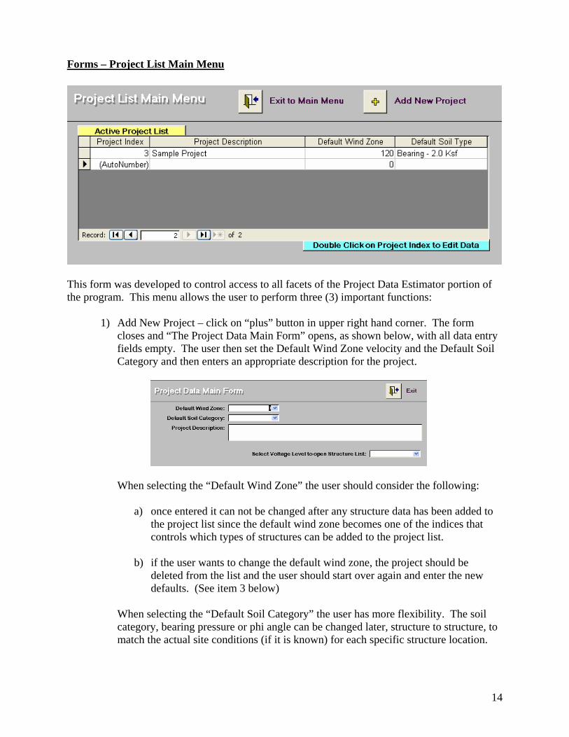
Forms – Project List Main Menu
This form was developed to control access to all facets of the Project Data Estimator portion of the program. This menu allows the user to perform three (3) important functions:
1) Add New Project – click on “plus” button in upper right hand corner. The form closes and “The Project Data Main Form” opens, as shown below, with all data entry fields empty. The user then set the Default Wind Zone velocity and the Default Soil Category and then enters an appropriate description for the project.
When selecting the “Default Wind Zone” the user should consider the following:
a) once entered it can not be changed after any structure data has been added to the project list since the default wind zone becomes one of the indices that controls which types of structures can be added to the project list.
b) if the user wants to change the default wind zone, the project should be
deleted from the list and the user should start over again and enter the new defaults. (See item 3 below)
When selecting the “Default Soil Category” the user has more flexibility. The soil
category, bearing pressure or phi angle can be changed later, structure to structure, to match the actual site conditions (if it is known) for each specific structure location.
15
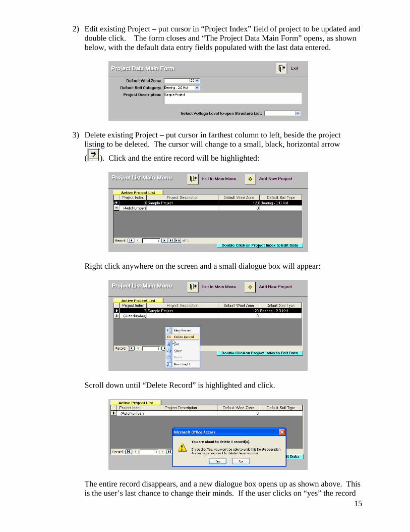
2) Edit existing Project – put cursor in “Project Index” field of project to be updated and double click. The form closes and “The Project Data Main Form” opens, as shown below, with the default data entry fields populated with the last data entered.
3) Delete existing Project – put cursor in farthest column to left, beside the project
listing to be deleted. The cursor will change to a small, black, horizontal arrow
( ). Click and the entire record will be highlighted:
Right click anywhere on the screen and a small dialogue box will appear:
Scroll down until “Delete Record” is highlighted and click.
The entire record disappears, and a new dialogue box opens up as shown above. This
is the user’s last chance to change their minds. If the user clicks on “yes” the record
16
is permanently deleted and all structural and foundation data associated with that project listing are flushed from the project data table. If the user clicks on “no” the record is restored and the delete command closed without further action.
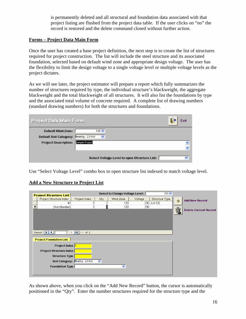
Forms – Project Data Main Form Once the user has created a base project definition, the next step is to create the list of structures required for project construction. The list will include the steel structure and its associated foundation, selected based on default wind zone and appropriate design voltage. The user has the flexibility to limit the design voltage to a single voltage level or multiple voltage levels as the project dictates. As we will see later, the project estimator will prepare a report which fully summarizes the number of structures required by type, the individual structure’s blackweight, the aggregate blackweight and the total blackweight of all structures. It will also list the foundations by type and the associated total volume of concrete required. A complete list of drawing numbers (standard drawing numbers) for both the structures and foundations.
Use “Select Voltage Level” combo box to open structure list indexed to match voltage level. Add a New Structure to Project List
As shown above, when you click on the “Add New Record” button, the cursor is automatically positioned in the “Qty”. Enter the number structures required for the structure type and the

17
associated foundation type that you will enter next. Keep in mind that the same structure type may be entered more than once, so that different foundation types (to reflect variable site soil conditions) can be entered. After entering the quantity in the field, strike your enter key, and the cursor will jump to the “Structure Type” field. This field is a pop down combo box, so the appropriate handle should appear automatically. Click on the down arrow in the box, a list of standard type structures matching the default wind zone and the selected voltage level will be displayed as shown below.
Scroll up or down until you find the want you want to use, click and it will be entered into the field. Note that the “Project Structure Index” and the “Structure Type” fields in the project foundation list have been added as well. To finish the you must select the “Soil Category” and “Foundation Type” inturn. As shown above the default soil category will already be listed in the “Soil Category” field. Depending on the local site conditions for this structure the soil category can be changed using the pop down combo box, if so desired.
Finally, use the pop down combo box in the “Foundation Type” field to enter the desired foundation type. Note that the available types of foundations listed in the combo box, will only match the soil category displayed in the “Soil Category” field. Therefore, the soil category must always be selected first. For estimating purposes and if site soil conditions are not readily available, it is recommended that you limit your choice of soil categories to either 32 deg phi for sandy soils for Caisson foundations or 2.0 ksf bearing pressures for spread footer types of foundations.
18
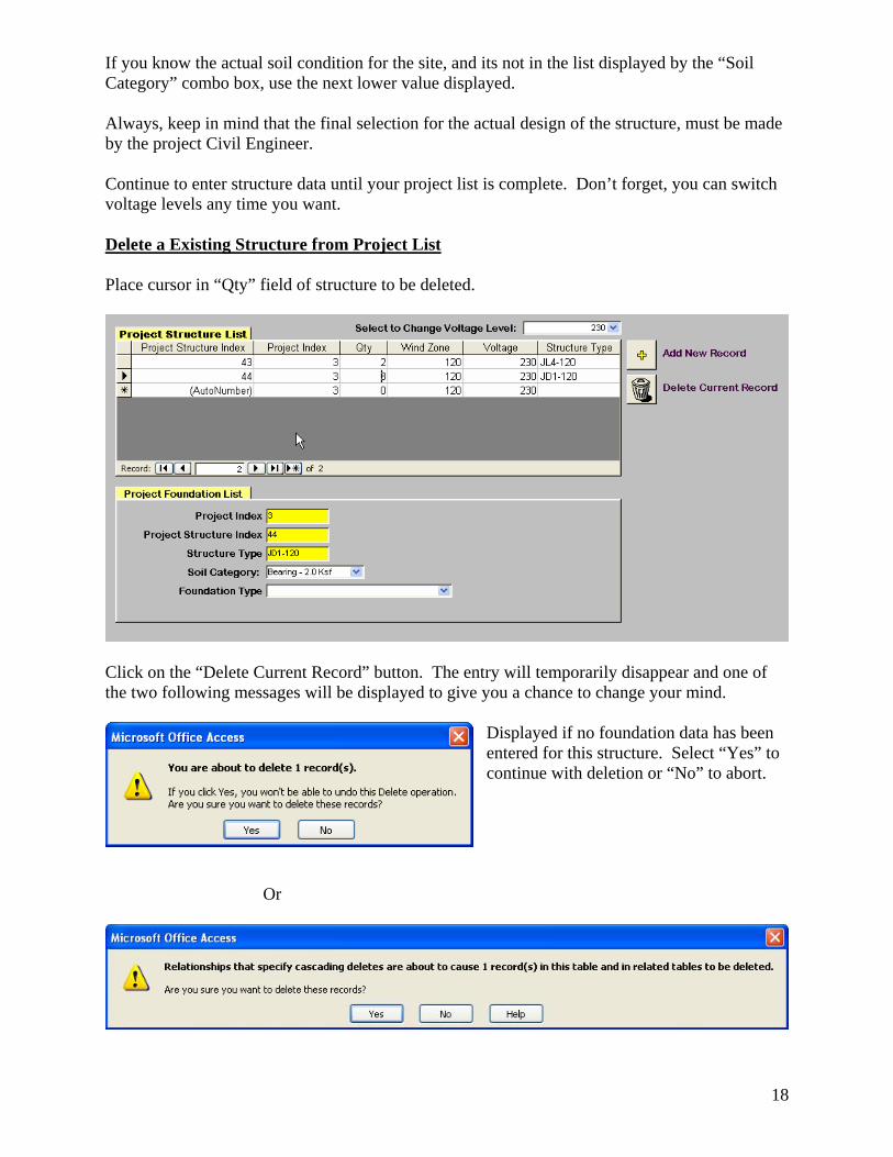
If you know the actual soil condition for the site, and its not in the list displayed by the “Soil Category” combo box, use the next lower value displayed. Always, keep in mind that the final selection for the actual design of the structure, must be made by the project Civil Engineer. Continue to enter structure data until your project list is complete. Don’t forget, you can switch voltage levels any time you want. Delete a Existing Structure from Project List Place cursor in “Qty” field of structure to be deleted.
Click on the “Delete Current Record” button. The entry will temporarily disappear and one of the two following messages will be displayed to give you a chance to change your mind.
Displayed if no foundation data has been entered for this structure. Select “Yes” to continue with deletion or “No” to abort.
Or
19
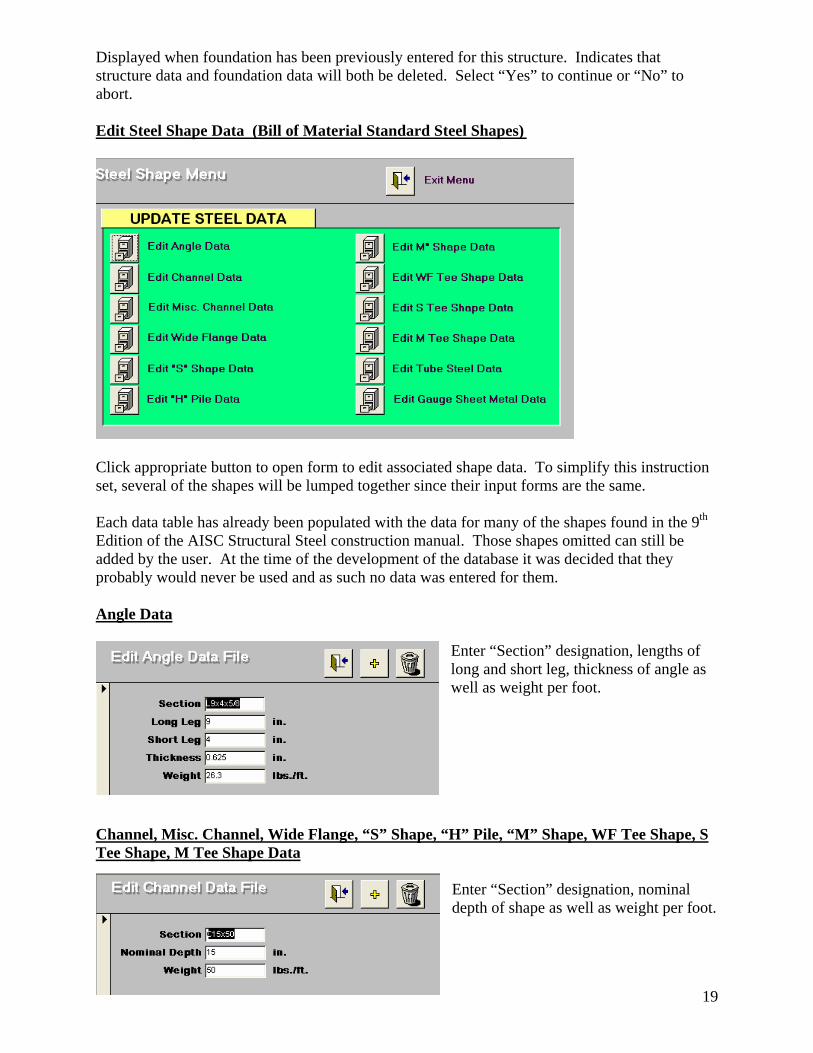
Displayed when foundation has been previously entered for this structure. Indicates that structure data and foundation data will both be deleted. Select “Yes” to continue or “No” to abort. Edit Steel Shape Data (Bill of Material Standard Steel Shapes)
Click appropriate button to open form to edit associated shape data. To simplify this instruction set, several of the shapes will be lumped together since their input forms are the same. Each data table has already been populated with the data for many of the shapes found in the 9th Edition of the AISC Structural Steel construction manual. Those shapes omitted can still be added by the user. At the time of the development of the database it was decided that they probably would never be used and as such no data was entered for them. Angle Data
Enter “Section” designation, lengths of long and short leg, thickness of angle as well as weight per foot.
Channel, Misc. Channel, Wide Flange, “S” Shape, “H” Pile, “M” Shape, WF Tee Shape, S Tee Shape, M Tee Shape Data
Enter “Section” designation, nominal depth of shape as well as weight per foot.
20
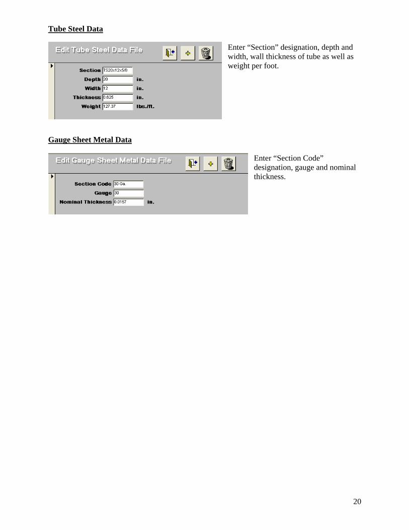
Tube Steel Data Enter “Section” designation, depth and width, wall thickness of tube as well as weight per foot.
Gauge Sheet Metal Data
Enter “Section Code” designation, gauge and nominal thickness.
21
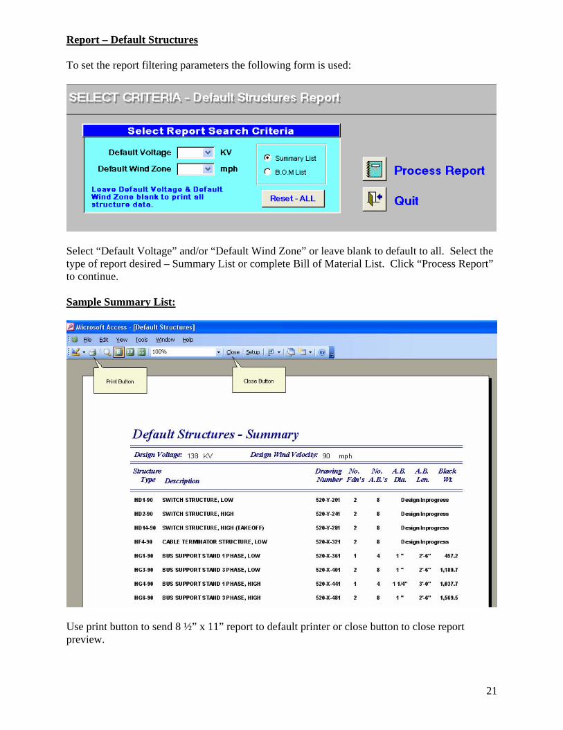
Report – Default Structures To set the report filtering parameters the following form is used:
Select “Default Voltage” and/or “Default Wind Zone” or leave blank to default to all. Select the type of report desired – Summary List or complete Bill of Material List. Click “Process Report” to continue. Sample Summary List:
Use print button to send 8 ½” x 11” report to default printer or close button to close report preview.
22
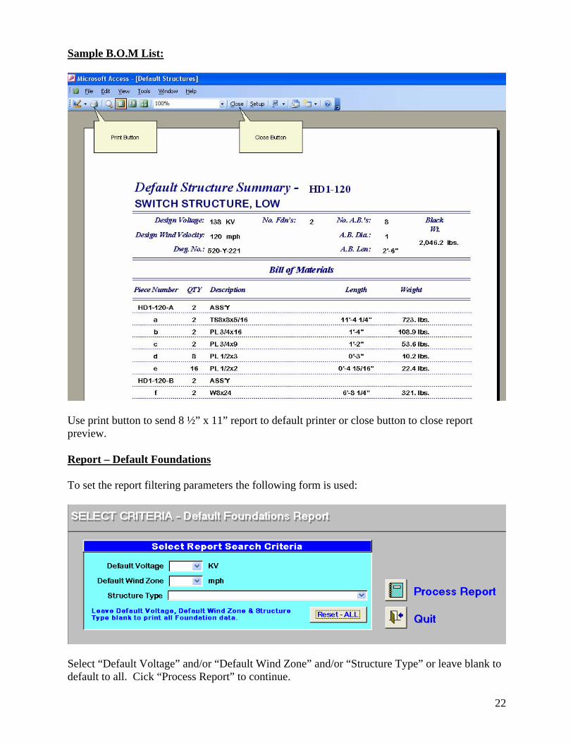
Sample B.O.M List:
Use print button to send 8 ½” x 11” report to default printer or close button to close report preview. Report – Default Foundations To set the report filtering parameters the following form is used:
Select “Default Voltage” and/or “Default Wind Zone” and/or “Structure Type” or leave blank to default to all. Cick “Process Report” to continue.
23
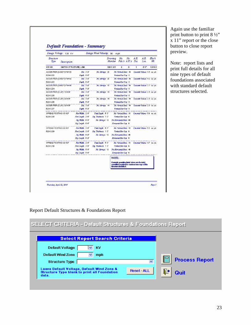
Again use the familiar print button to print 8 ½” x 11” report or the close button to close report preview. Note: report lists and print full details for all nine types of default foundations associated with standard default structures selected.
Report Default Structures & Foundations Report
24
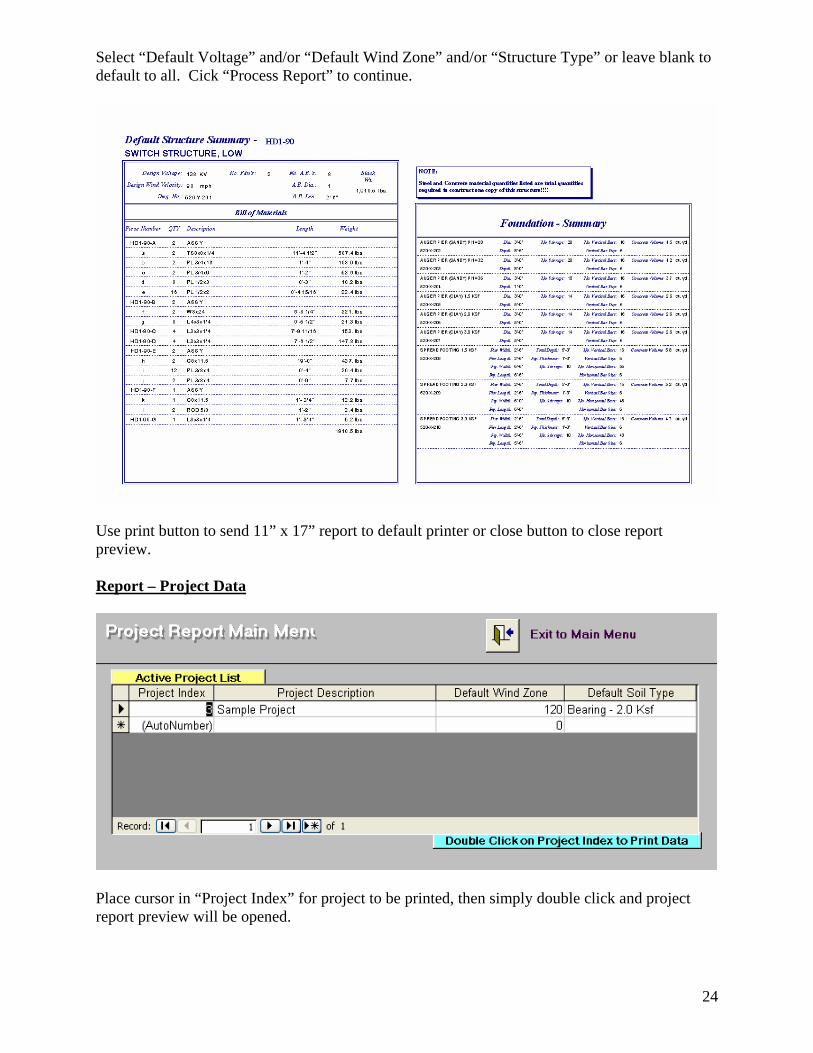
Select “Default Voltage” and/or “Default Wind Zone” and/or “Structure Type” or leave blank to default to all. Cick “Process Report” to continue.
Use print button to send 11” x 17” report to default printer or close button to close report preview. Report – Project Data
Place cursor in “Project Index” for project to be printed, then simply double click and project report preview will be opened.
25
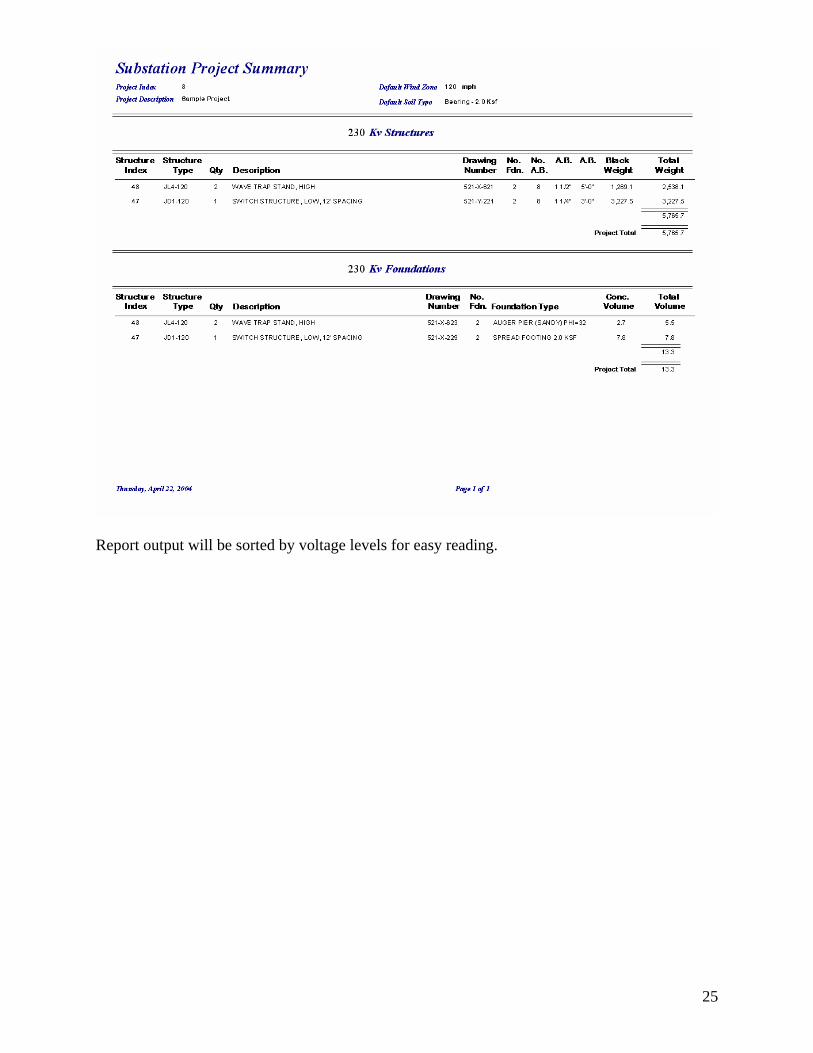
Report output will be sorted by voltage levels for easy reading.
26
Appendix A
Database Setup Instructions
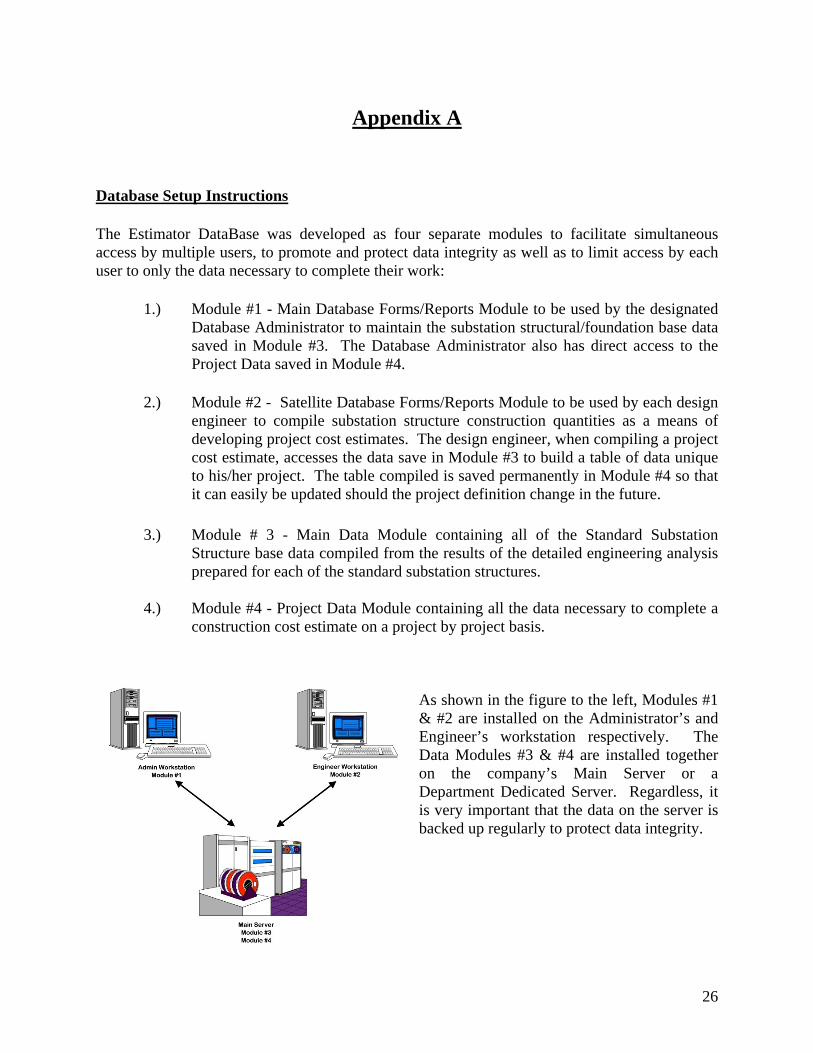
The Estimator DataBase was developed as four separate modules to facilitate simultaneous access by multiple users, to promote and protect data integrity as well as to limit access by each user to only the data necessary to complete their work:
1.) Module #1 - Main Database Forms/Reports Module to be used by the designated Database Administrator to maintain the substation structural/foundation base data saved in Module #3. The Database Administrator also has direct access to the Project Data saved in Module #4.
2.) Module #2 - Satellite Database Forms/Reports Module to be used by each design engineer to compile substation structure construction quantities as a means of developing project cost estimates. The design engineer, when compiling a project cost estimate, accesses the data save in Module #3 to build a table of data unique to his/her project. The table compiled is saved permanently in Module #4 so that it can easily be updated should the project definition change in the future.
3.) Module # 3 - Main Data Module containing all of the Standard Substation
Structure base data compiled from the results of the detailed engineering analysis prepared for each of the standard substation structures.
4.) Module #4 - Project Data Module containing all the data necessary to complete a
construction cost estimate on a project by project basis.
As shown in the figure to the left, Modules #1 & #2 are installed on the Administrator’s and Engineer’s workstation respectively. The Data Modules #3 & #4 are installed together on the company’s Main Server or a Department Dedicated Server. Regardless, it is very important that the data on the server is backed up regularly to protect data integrity.
27
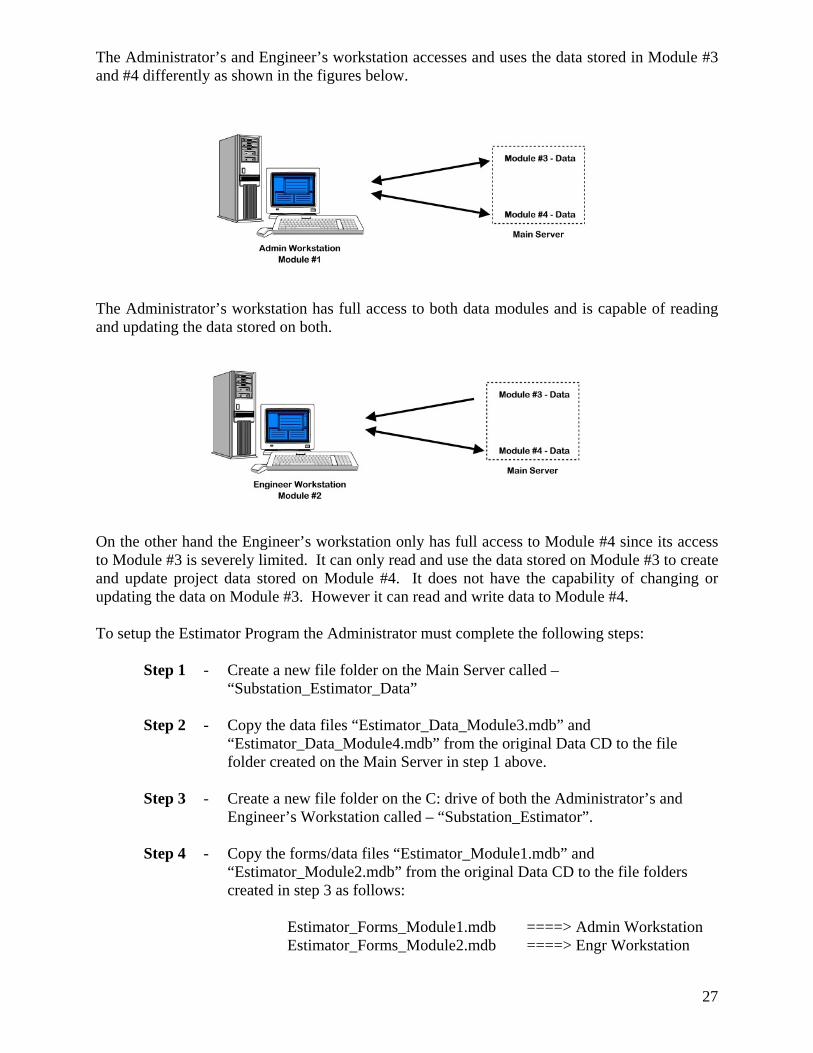
The Administrator’s and Engineer’s workstation accesses and uses the data stored in Module #3 and #4 differently as shown in the figures below.
The Administrator’s workstation has full access to both data modules and is capable of reading and updating the data stored on both.
On the other hand the Engineer’s workstation only has full access to Module #4 since its access to Module #3 is severely limited. It can only read and use the data stored on Module #3 to create and update project data stored on Module #4. It does not have the capability of changing or updating the data on Module #3. However it can read and write data to Module #4. To setup the Estimator Program the Administrator must complete the following steps: Step 1 - Create a new file folder on the Main Server called –
“Substation_Estimator_Data” Step 2 - Copy the data files “Estimator_Data_Module3.mdb” and
“Estimator_Data_Module4.mdb” from the original Data CD to the file folder created on the Main Server in step 1 above.
Step 3 - Create a new file folder on the C: drive of both the Administrator’s and
Engineer’s Workstation called – “Substation_Estimator”. Step 4 - Copy the forms/data files “Estimator_Module1.mdb” and
“Estimator_Module2.mdb” from the original Data CD to the file folders created in step 3 as follows:
Estimator_Forms_Module1.mdb ====> Admin Workstation Estimator_Forms_Module2.mdb ====> Engr Workstation
28
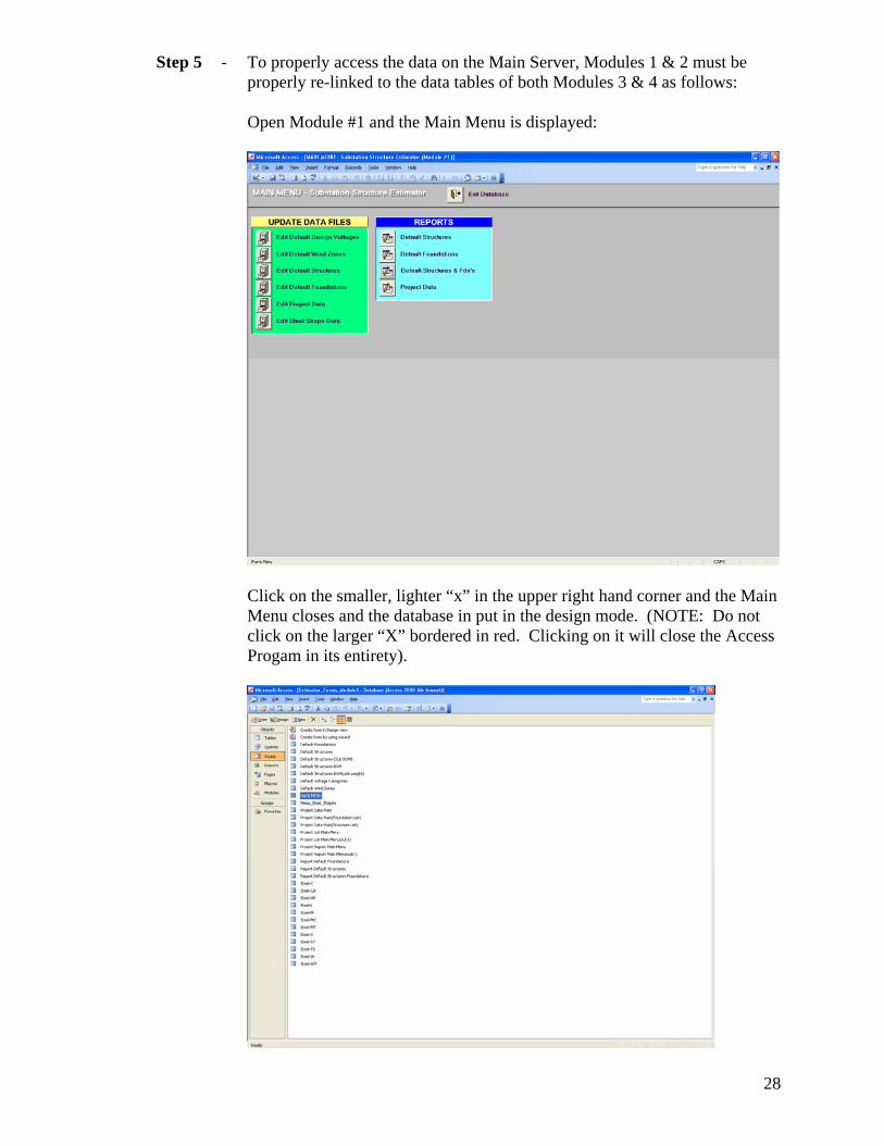
Step 5 - To properly access the data on the Main Server, Modules 1 & 2 must be properly re-linked to the data tables of both Modules 3 & 4 as follows:
Open Module #1 and the Main Menu is displayed:
Click on the smaller, lighter “x” in the upper right hand corner and the Main
Menu closes and the database in put in the design mode. (NOTE: Do not click on the larger “X” bordered in red. Clicking on it will close the Access Progam in its entirety).
29
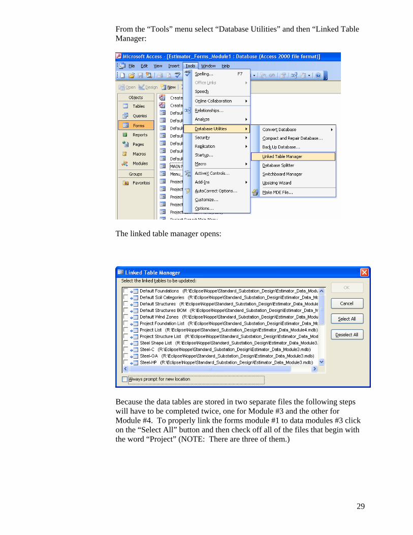
From the “Tools” menu select “Database Utilities” and then “Linked Table Manager:
The linked table manager opens:
Because the data tables are stored in two separate files the following steps
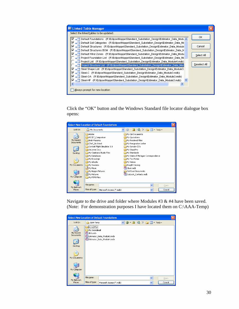
will have to be completed twice, one for Module #3 and the other for Module #4. To properly link the forms module #1 to data modules #3 click on the “Select All” button and then check off all of the files that begin with the word “Project” (NOTE: There are three of them.)
30
Click the “OK” button and the Windows Standard file locator dialogue box
opens:
Navigate to the drive and folder where Modules #3 & #4 have been saved.
(Note: For demonstration purposes I have located them on C:\AAA-Temp)
31
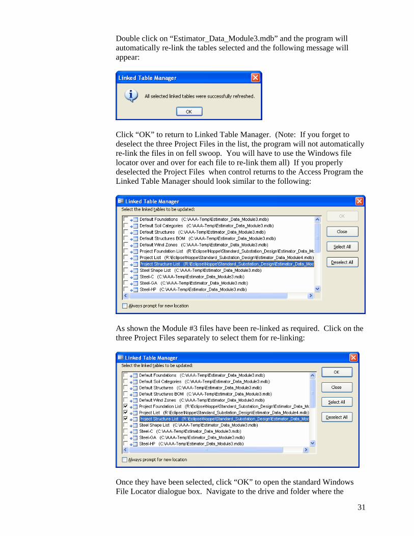
Double click on “Estimator_Data_Module3.mdb” and the program will
automatically re-link the tables selected and the following message will appear:
Click “OK” to return to Linked Table Manager. (Note: If you forget to
deselect the three Project Files in the list, the program will not automatically re-link the files in on fell swoop. You will have to use the Windows file locator over and over for each file to re-link them all) If you properly deselected the Project Files when control returns to the Access Program the Linked Table Manager should look similar to the following:
As shown the Module #3 files have been re-linked as required. Click on the
three Project Files separately to select them for re-linking:
Once they have been selected, click “OK” to open the standard Windows
File Locator dialogue box. Navigate to the drive and folder where the
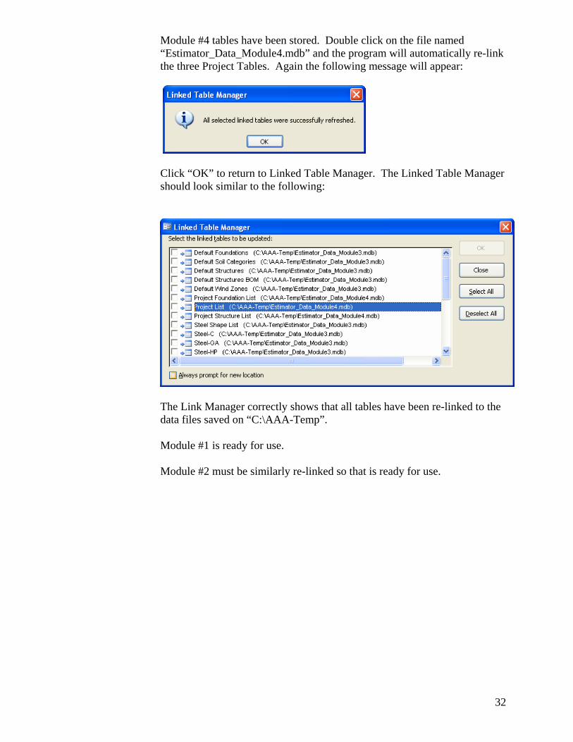
32
Module #4 tables have been stored. Double click on the file named “Estimator_Data_Module4.mdb” and the program will automatically re-link the three Project Tables. Again the following message will appear:
Click “OK” to return to Linked Table Manager. The Linked Table Manager
should look similar to the following:
The Link Manager correctly shows that all tables have been re-linked to the
data files saved on “C:\AAA-Temp”. Module #1 is ready for use. Module #2 must be similarly re-linked so that is ready for use.
Related Documents