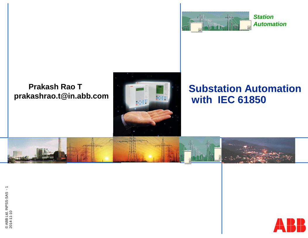
© ABB Ltd. INPSS-SAS - 1 2014-11-10 Substation Automation with IEC 61850 Prakash Rao T [email protected] Station Automation

Welcome message from author
This document is posted to help you gain knowledge. Please leave a comment to let me know what you think about it! Share it to your friends and learn new things together.
Transcript
©A
BB
Ltd.
INP
SS
-SA
S-1
2014
-11-
10
Substation Automationwith IEC 61850
Prakash Rao [email protected]
StationAutomation

Contents
§ Why Substation Automation?
§ IEC61850 Standard
§ Interoperability
§ What is GOOSE?
§ Engineering Workflow
§ Micro SCADA Pro
§© ABB Group§November 10, 2014 | Slide 2

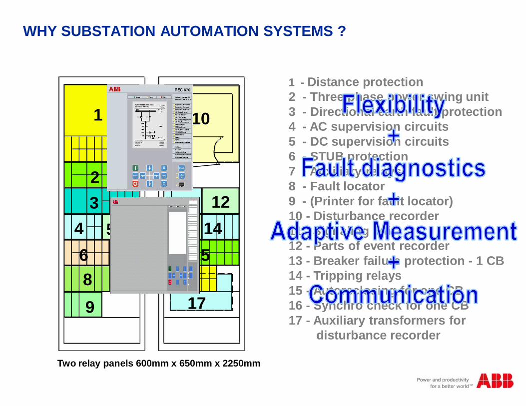
WHY SUBSTATION AUTOMATION SYSTEMS ?
vThe technological developments that led to the present availability of fast,powerful microprocessors and communication systems give us thepossibility to build Substation Automation Systems (SAS).
vThe substation secondary equipment evolved from electro-mechanicaldevices to microprocessor based numerical devices with built incommunication features.
vThis in turn provided the possibility of implementing SAS using severalintelligent electronic devices (IEDs) to perform the required functions(protection, local and remote monitoring, control, etc.).
vThus need arose for efficient communication among the IED’s usingappropriate protocols
WHY SUBSTATION AUTOMATION SYSTEMS ?
1 - Distance protection2 - Three phase power swing unit3 - Directional earth fault protection4 - AC supervision circuits5 - DC supervision circuits6 - STUB protection7 - Auxiliary relays8 - Fault locator9 - (Printer for fault locator)10 - Disturbance recorder11 - Signaling unit12 - Parts of event recorder13 - Breaker failure protection - 1 CB14 - Tripping relays15 - Autoreclosing for one CB16 - Synchro check for one CB17 - Auxiliary transformers for
disturbance recorder
1
23
4 56 789
10
11 1213 14
1516
17
Two relay panels 600mm x 650mm x 2250mm
The main requirement = Right information with ITG
M
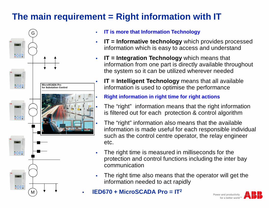
§ IT is more that Information Technology
§ IT = Informative technology which provides processedinformation which is easy to access and understand
§ IT = Integration Technology which means thatinformation from one part is directly available throughoutthe system so it can be utilized wherever needed
§ IT = Intelligent Technology means that all availableinformation is used to optimise the performance
§ Right information in right time for right actions
§ The “right” information means that the right informationis filtered out for each protection & control algorithm
§ The “right” information also means that the availableinformation is made useful for each responsible individualsuch as the control centre operator, the relay engineeretc.
§ The right time is measured in milliseconds for theprotection and control functions including the inter baycommunication
§ The right time also means that the operator will get theinformation needed to act rapidly
§ IED670 + MicroSCADA Pro = IT2

Type of disturbanceTime to recoverNo. of customers affected
Repair and Maintenance
Work reportWork order
CustomerService
Recovery informationCustomer complaints
StationAutomation
Customer
AssetManagement
SparesFault statistics
Disturbance informationDisturbance report
Engineering
Asset recordsDisturbance report
Sales
Customers affected
Accounting
ReportsReports
Compensation
Real-time informationDisturbance records
Control Center
Managing the Power Grid

Why we need Substation Automation System?
§ To manage
- Repetitive operation
- Complex operation
§ To have
- Accurate, timely information about all powersystem components
- Faster response
- Quicker decisions
- Faster restoration after breakdown
- Less or nil human interference
- Lower operational cost
§© ABB Group§November 10, 2014 | Slide 7
Why Automation?
Benefits
§ Sequential control with interlocks
§ Increased safety of personnel and of equipment
§ Increased security availability, reliability and efficiency.
§ Reduced start up and shut down time.
§ Reduced configuration time.
§ Less or nil dependence on human beings
§ Lower operational cost.

Why Automation?
§ To supply the power, meeting the power quality standards:
§ Reliability : Maintain uninterrupted power supply§ Availability : Meet the demand.§ Quality : limit ,within permitted range,
Frequency deviationsVoltage FluctuationsTransientsHarmonics distortions
The electrical utility should meet the above with optimum economy.

What is Substation Automation ?
§ Substitution for conventional control panels
§ Substitution for other sub systems
§ A more efficient way of controlling your substation
8
§ A combination of
§ Protection
§ Monitoring
§ Control
§ Communication
What is Substation Automation ?

Trends in Substation Automation (SA)

ABB Substation Automation Systems > 20 years
1980ies: ABB introduces Substation Control with SPA (SCS100) and Ethernet (SCS200)1990ies: ABB implement Substation Automation with LON and IEC60870-5-1032000 + : ABB implement Substation Automation with IEC61850
§ABB Network Partner AG
§C
§E
§COM581
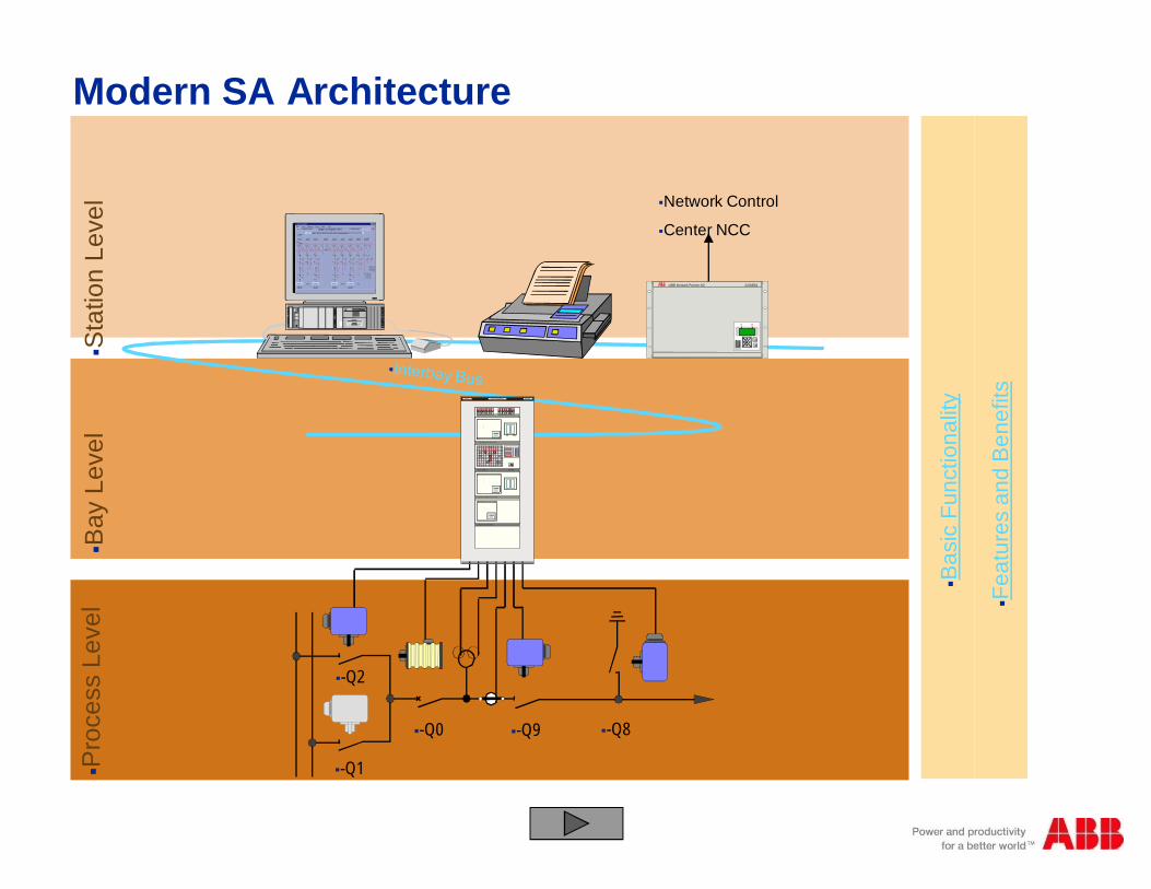
§Network Control
§Center NCC
§-Q1
§-Q0 §-Q8§-Q9
§-Q2
=D04+R01225k V L IG NE ABO BO 1ABB
125VDC Dis tributuion Battery A 125VDC Dis tributuion Battery B
BAY CO NTRO L RELAY REC316*4
1
ABB A B B N e tw o r k P a r tn e rREL 3 1 6 * 4
2
43
5678
9
1 21 1
1 31 41 51 6
1 0
LO CAL CO NTRO L M ETERING
LINE PRO TECTIO N RELAY REL316*4
1
ABB A B B N e tw o r k P a r tn e rREL 3 1 6 * 4
2
43
5678
9
1 21 1
1 31 41 51 6
1 0
BUSBAR PRO TECTIO N REB500
ABB A B B N e tw o r k P a r tn e rREB5 0 0
ABB
=D04 ABOBO 1
- Q2S E L
- Q1S E L
- Q0S E L
= W 1
= W 2
F E R M E RO U V R IR
E X EE S C
L A M P ET E S T E
D IS T A N C E
L OC
ABBP OW E R MONIT ORING UNIT
§Pro
cess
Leve
l§B
ayLe
vel
§Sta
tion
Leve
l
§Fea
ture
san
dB
enef
its
§Bas
icFu
nctio
nalit
y
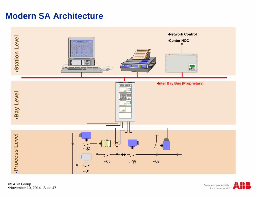
Modern SA Architecture
§t
§i §i§t §l
§-Q1
§-Q0
§-Q8
§Fee
derM
arsh
allin
g
§-Q9
§-Q2
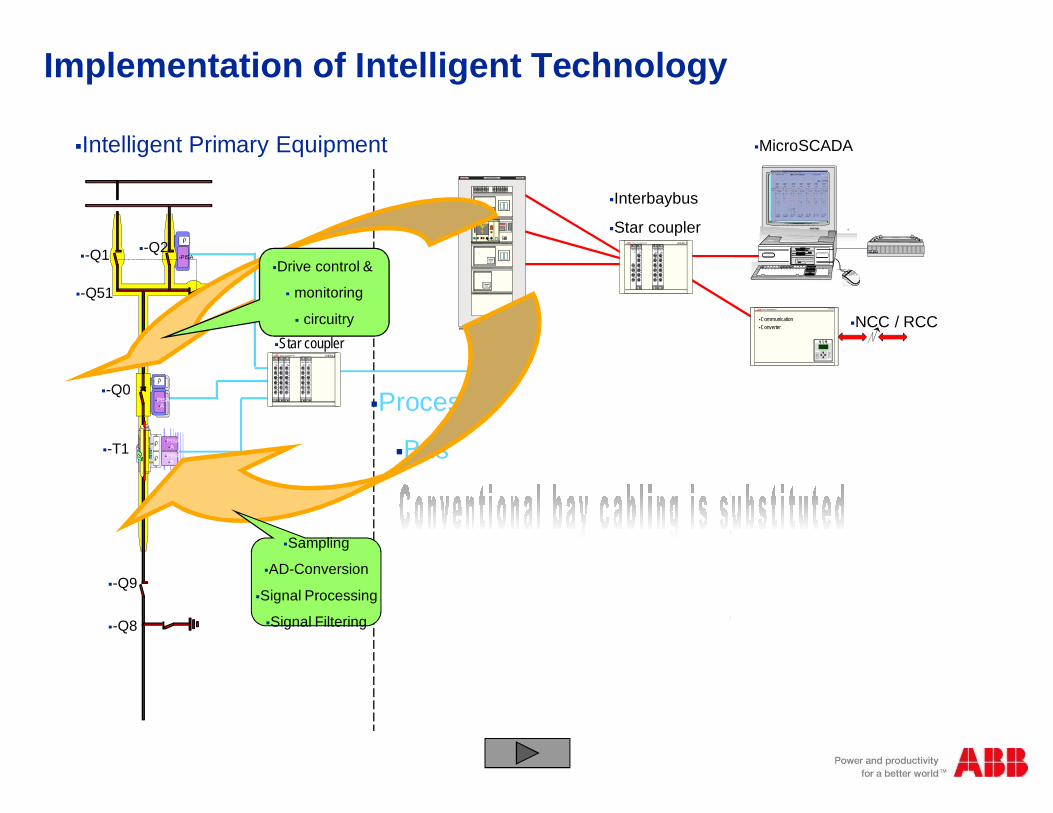
§Intelligent Primary Equipment
§PISA
§PISA§A§PISA§B
§PISA§A
§-Q1 §-Q2
§-Q51
§-Q0
§-T1
§-Q9
§-Q8
§Process
§Bus
§Process bus§Star coupler§ABB §Power Automation AG §RER111
§500SCM§01
§Rx3
§Tx3
§Rx2
§Tx2
§Rx1
§Tx1
§500SCM§01
§Rx3
§Tx3
§Rx2
§Tx2
§Rx1
§Tx1
§500SCM§01
§Rx3
§Tx3
§Rx2
§Tx2
§Rx1
§Tx1
§500SCM§01
§Rx3
§Tx3
§Rx2
§Tx2
§Rx1
§Tx1
§500SCM§01
§Rx3
§Tx3
§Rx2
§Tx2
§Rx1
§Tx1
§Interbaybus
§Star coupler §d§g§i§t§a§l
§Tx2
§Rx1
§Tx1
§500SCM§01
§Rx3
§Tx3
§Rx2
§Tx2
§Rx1
§Tx1 §d§i§g§i§t§a§l
§NCC / RCC
§MicroSCADA
§ABB§Power Automation AG §COM581
§C
§Communication§Converter
§ABB §Power Automation AG §RER111
§500SCM§01
§Rx3
§Tx3
§Rx2
§Tx2
§Rx1
§Tx1
§500SCM§01
§Rx3
§Tx3
§Rx2
§Tx2
§Rx1
§Tx1
§500SCM§01
§Rx3
§Tx3
§Rx2
§Tx2
§Rx1
§Tx1
§500SCM§01
§Rx3
§Tx3
§Rx2
=D04+R01225k V L IG NE ABO BO 1ABB
125VDC Dis tributuion Battery A 125VDC Dis tributuion Battery B
BAY CO NTRO L RELAY REC316*4
1
ABB A B B N e tw o r k P a r tn e rREL 3 1 6 * 4
2
43
5678
9
1 21 1
1 31 41 51 6
1 0
LO CAL CO NTRO L M ETERING
LINE PRO TECTIO N RELAY REL316*4
1
ABB A B B N e tw o r k P a r tn e rREL 3 1 6 * 4
2
43
5678
9
1 21 1
1 31 41 51 6
1 0
BUSBAR PRO TECTIO N REB500
ABB A B B N e tw o r k P a r tn e rREB5 0 0
ABB
=D04 ABOBO 1
- Q2S E L
- Q1S E L
- Q0S E L
= W 1
= W 2
F E R M E RO U V R IR
E X EE S C
L A M P ET E S T E
D IS T A N C E
L OC
ABBP OW E R MONIT ORING UNIT
§? §LOCAL§REMOTE
§SET§OPERATION
§M
§M
§M
§Drive control &
§ monitoring
§ circuitry
§Sampling
§AD-Conversion
§Signal Processing
§Signal Filtering
Implementation of Intelligent Technology
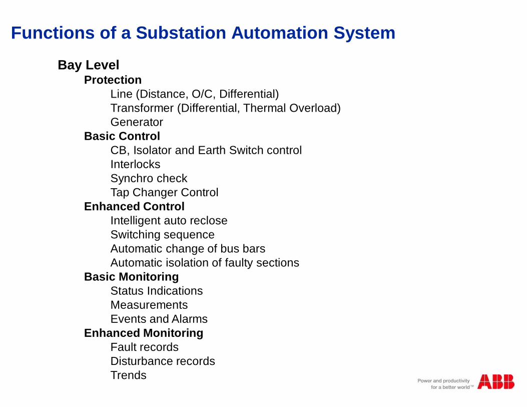
Bay LevelProtection
Line (Distance, O/C, Differential)Transformer (Differential, Thermal Overload)Generator
Basic ControlCB, Isolator and Earth Switch controlInterlocksSynchro checkTap Changer Control
Enhanced ControlIntelligent auto recloseSwitching sequenceAutomatic change of bus barsAutomatic isolation of faulty sections
Basic MonitoringStatus IndicationsMeasurementsEvents and Alarms
Enhanced MonitoringFault recordsDisturbance recordsTrends
Functions of a Substation Automation System

Other Enhanced Station Level Functions
Analysis and DiagnosticsSuppression of non-relevant alarmsFailure AnalysisSequence of Events AnalysisAutomatically generated fault reportsAutomatic Disturbance evaluation
Support for intelligent operationIntegrated Condition MonitoringIntegrated Substation DiagnosticsPlausibility checksLimit SupervisionAlarm categorization (class 1, class 2, etc.,)Automatic notification of problemsMaintenance prediction (performance based)Detection of incipient faults and preventive measuresAutomatic Load sheddingAutomatic Power restoration
Functions of a Substation Automation System
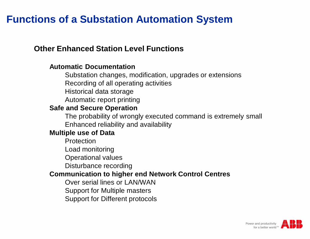
Other Enhanced Station Level Functions
Automatic DocumentationSubstation changes, modification, upgrades or extensionsRecording of all operating activitiesHistorical data storageAutomatic report printing
Safe and Secure OperationThe probability of wrongly executed command is extremely smallEnhanced reliability and availability
Multiple use of DataProtectionLoad monitoringOperational valuesDisturbance recording
Communication to higher end Network Control CentresOver serial lines or LAN/WANSupport for Multiple mastersSupport for Different protocols
Functions of a Substation Automation System
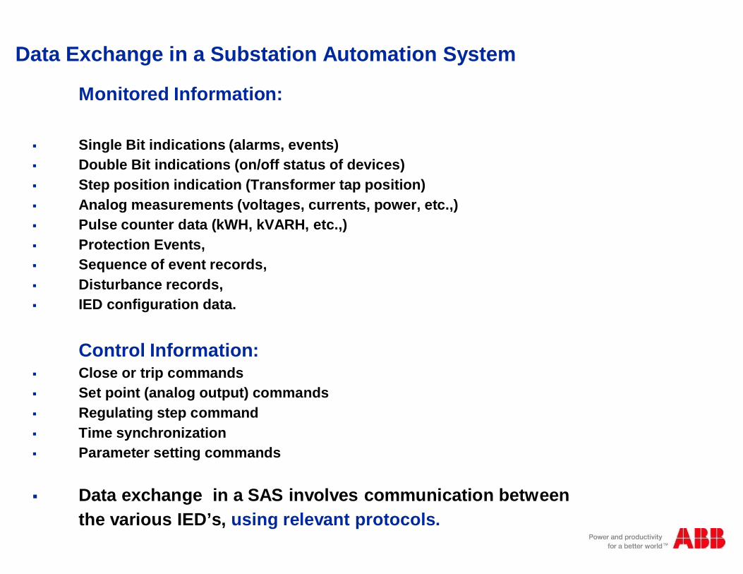
Data Exchange in a Substation Automation System
Monitored Information:
§ Single Bit indications (alarms, events)§ Double Bit indications (on/off status of devices)§ Step position indication (Transformer tap position)§ Analog measurements (voltages, currents, power, etc.,)§ Pulse counter data (kWH, kVARH, etc.,)§ Protection Events,§ Sequence of event records,§ Disturbance records,§ IED configuration data.
Control Information:§ Close or trip commands§ Set point (analog output) commands§ Regulating step command§ Time synchronization§ Parameter setting commands
§ Data exchange in a SAS involves communication betweenthe various IED’s, using relevant protocols.

Intelligent SA Architecture
§ABB Network Partner AG
§C
§E
§COM581
§Network Control
§Center NCC
§PIS
A
§PIS
A§A
§PIS
A§B
§PIS
A§A
§-Q1
§-Q2
§-Q51
§-Q0 §-T1 §-Q9 §-Q8
=D04+R01225k V L IG NE ABO BO 1ABB
125VDC Dis tributuion Battery A 125VDC Dis tributuion Battery B
BAY CO NTRO L RELAY REC316*4
1
ABB A B B N e tw o r k P a r tn e rREL 3 1 6 * 4
2
43
5678
9
1 21 1
1 31 41 51 6
1 0
LO CAL CO NTRO L M ETERING
LINE PRO TECTIO N RELAY REL316*4
1
ABB A B B N e tw o r k P a r tn e rREL 3 1 6 * 4
2
43
5678
9
1 21 1
1 31 41 51 6
1 0
BUSBAR PRO TECTIO N REB500
ABB A B B N e tw o r k P a r tn e rREB5 0 0
ABB
=D04 ABOBO 1
- Q2S E L
- Q1S E L
- Q0S E L
= W 1
= W 2
F E R M E RO U V R IR
E X EE S C
L A M P ET E S T E
D IS T A N C E
L OC
ABBP OW E R MONIT ORING UNIT
§? §LOCAL§REMOTE
§SET§OPERATION
§M
§M
§M
§Bas
icFu
nctio
nalit
y
§FE
ATU
RE
SA
ND
BE
NE
FITS
§Pro
cess
Leve
l§B
ayLe
vel
§Sta
tion
Leve
l

Design Principles of Modern SA
§Mainstream Hardware
§Features
§Mainstream Software platforms§Integrated SA System§• Control
§• Monitoring (protection)
§• Disturbance recording
§• Metering
§• etc.§Open System§Bus (serial) communication§Using fibre optic media
§for communication§Compact design§Decentralised system structure§closer to process§No conventional mimic board
§Less inventories and spare parts
§Benefits
§Less training & Familiarisation§Less Hardware and panels§Less operation and maintenance
§costs§More availability§Minimising outage breaks§Integration of third-party
§equipment§Less cabling and installation
§costs§Less testing and commissioning
§costs§Less space and civil works
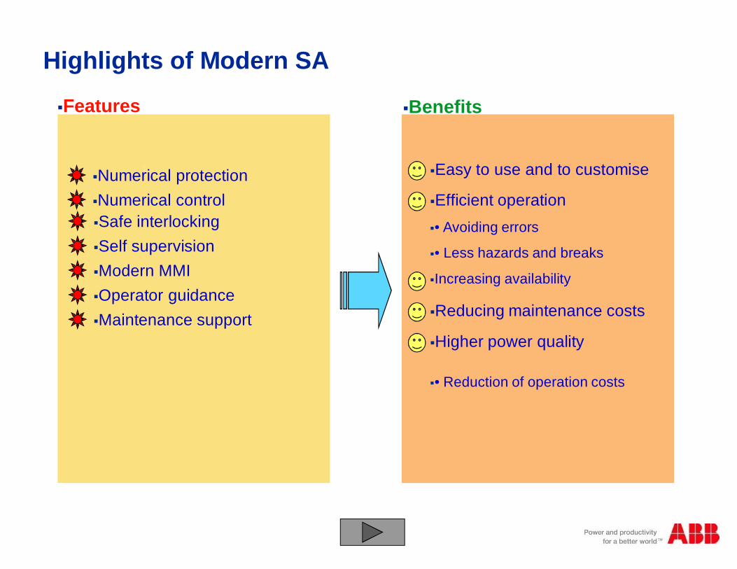
Highlights of Modern SA
§Features
§Numerical protection§Numerical control
§Benefits
§Safe interlocking§Self supervision§Modern MMI§Operator guidance§Maintenance support
§Easy to use and to customise
§Efficient operation§• Avoiding errors
§• Less hazards and breaks
§Increasing availability
§• Reduction of operation costs
§Reducing maintenance costs
§Higher power quality
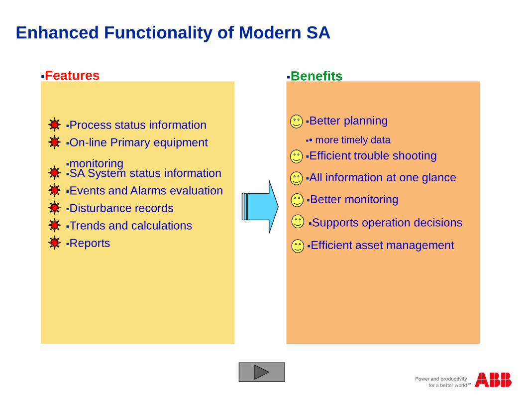
Enhanced Functionality of Modern SA
§Features
§Process status information§On-line Primary equipment
§monitoring
§Benefits
§SA System status information§Events and Alarms evaluation§Disturbance records§Trends and calculations§Reports
§Better planning§• more timely data§Efficient trouble shooting
§All information at one glance
§Better monitoring
§Efficient asset management
§Supports operation decisions
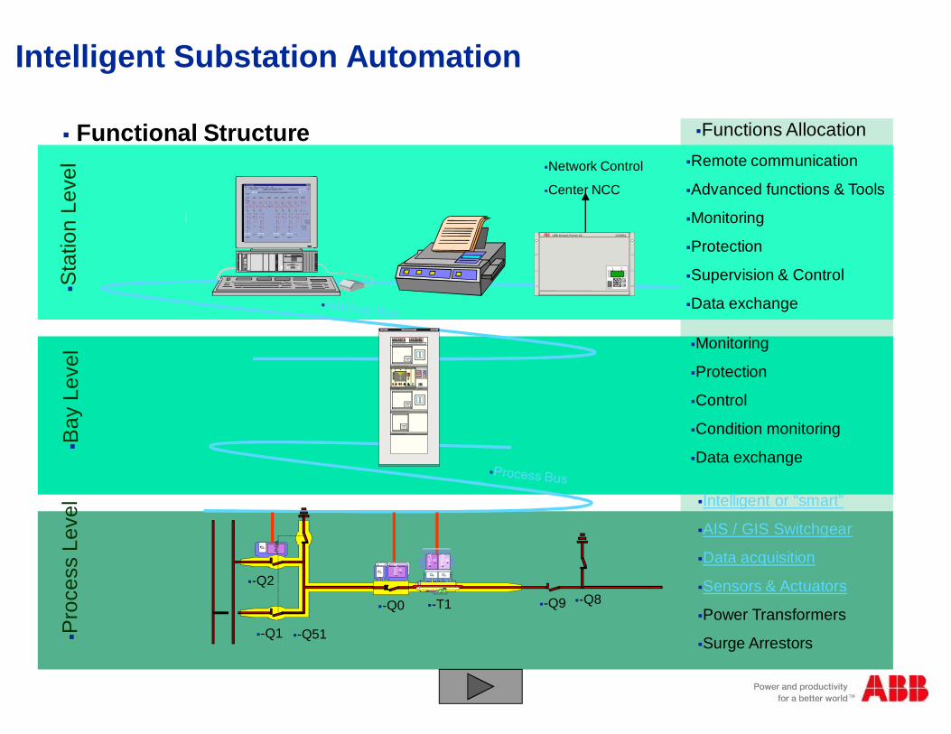
§Intelligent or “smart”
§AIS / GIS Switchgear
§Data acquisition
§Sensors & Actuators
§Power Transformers
§Surge Arrestors
§ABB Network Partner AG
§C
§E
§COM581
§Network Control
§Center NCC
§PIS
A
§PIS
A§A
§PIS
A§B
§PIS
A§A
§-Q1
§-Q2
§-Q51
§-Q0 §-T1 §-Q9 §-Q8
§Monitoring
§Protection
§Control
§Condition monitoring
§Data exchange
§Remote communication
§Advanced functions & Tools
§Monitoring
§Protection
§Supervision & Control
§Data exchange
§ Functional Structure §Functions Allocation
=D04+R01225k V L IG NE ABO BO 1ABB
125VDC Dis tributuion Battery A 125VDC Dis tributuion Battery B
BAY CO NTRO L RELAY REC316*4
1
ABB A B B N e tw o r k P a r tn e rREL 3 1 6 * 4
2
43
5678
9
1 21 1
1 31 41 51 6
1 0
LO CAL CO NTRO L M ETERING
LINE PRO TECTIO N RELAY REL316*4
1
ABB A B B N e tw o r k P a r tn e rREL 3 1 6 * 4
2
43
5678
9
1 21 1
1 31 41 51 6
1 0
BUSBAR PRO TECTIO N REB500
ABB A B B N e tw o r k P a r tn e rREB5 0 0
ABB
=D04 ABOBO 1
- Q2S E L
- Q1S E L
- Q0S E L
= W 1
= W 2
F E R M E RO U V R IR
E X EE S C
L A M P ET E S T E
D IS T A N C E
L OC
ABBP OW E R MONIT ORING UNIT
§? §LOCAL§REMOTE
§SET§OPERATION
§M
§M
§M
§Pro
cess
Leve
l§B
ayLe
vel
§Sta
tion
Leve
lIntelligent Substation Automation
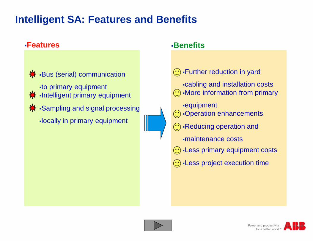
Intelligent SA: Features and Benefits
§Features
§Bus (serial) communication
§to primary equipment
§Benefits
§Further reduction in yard
§cabling and installation costs§More information from primary
§equipment§Operation enhancements
§Reducing operation and
§maintenance costs
§Intelligent primary equipment
§Sampling and signal processing
§locally in primary equipment
§Less primary equipment costs
§Less project execution time

§ABB
§Interbay bus 1§Interbay bus 2§Phase L1
§PISA
§PISA
§PISA§PISA
§PISA§A
§PISA§A§PISA§B
§opt. §opt.§el.
§opt. §opt.§el.
§Abgangsschutz I
§Sternkoppler§Feldleitgerät
§Abgangsschutz II
§Line Protection 1
§Bay Controller
§Line Protection 2
§Busbar Protection
§Star Coupler
§Process Bus
§Sensors for
§current &
§voltage
§measurement
§Actuator for
§circuit breaker
§control
§Actuator for
§isolator &earthing
§switch control
Intelligent SA: Control, Protection and Sensors=D04+R01225kV LIGNE ABOBO 1ABB
125VDC Distributuion Battery A 125VDC Distributuion Battery B
BAY CONTROL RELAY REC316*4
1
ABB ABB Ne twork Pa rtne r REL316*4
2
43
5678
9
1211
13141516
10
LOCAL CONTROL METERING
LINE PROTECTION RELAY REL316*4
1
ABB ABB Ne twork Pa rtne r REL316*4
2
43
5678
9
1211
13141516
10
BUSBAR PROTECTION REB500
ABB ABB Ne twork Pa rtne r REB500
ABB
=D04 ABOBO 1
-Q2SEL
-Q1SEL
-Q0SEL
=W1
=W2
FERM ERO UVRIR
EXEESC
LAM PETESTE
DISTANCE
LO C
ABBPOWER MONITORING UNIT
§? §LOCAL
§REMOTE
§SET
§OPERATION
§M
§M
§M
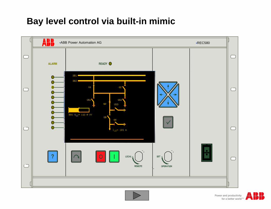
§ABB Power Automation AG §REC580
§BB1:UL1=500kV§IL1=0A
§One row with informations, etc..............................................
§IL1=0A
§U=5
00kV
§U=5
00kV
§Q1 §Q01 §Q61 §Q63
§Q51 §Q53 §Q55 §Q57
§Q15 §Q91
§Q81
§Q03 §Q64 §Q62 §Q02 §Q2
§Q25
§Q56 §Q54 §Q52§Q58
§Q92
§Q82
§BB1:UL1=500kV§IL1=0A
§One row with informations, etc..............................................
§IL1=0A
§U=5
00kV
§U=5
00kV
§Q1 §Q01 §Q61 §Q63
§Q51 §Q53 §Q55 §Q57
§Q15 §Q91
§Q81
§Q03 §Q64 §Q62 §Q02 §Q2
§Q25
§Q56 §Q54 §Q52§Q58
§Q92
§Q82
Bay level control via built-in mimic
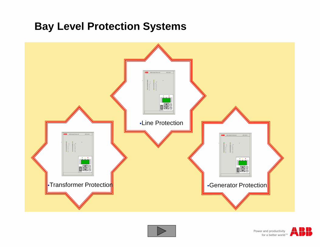
Bay Level Protection Systems
§C
§E
§1
§2§3
§4§5§6
§7§8
§9
§10§11§12§13§14
§15§16
§ABB Network Partner AG §REC 316*4
§Line Protection
§C
§E
§1
§2§3
§4§5§6
§7§8
§9
§10§11§12§13§14
§15§16
§ABB Network Partner AG §REC 316*4
§Transformer Protection
§C
§E
§1
§2§3
§4§5§6
§7§8
§9
§10§11§12§13§14
§15§16
§ABB Network Partner AG §REC 316*4
§Generator Protection
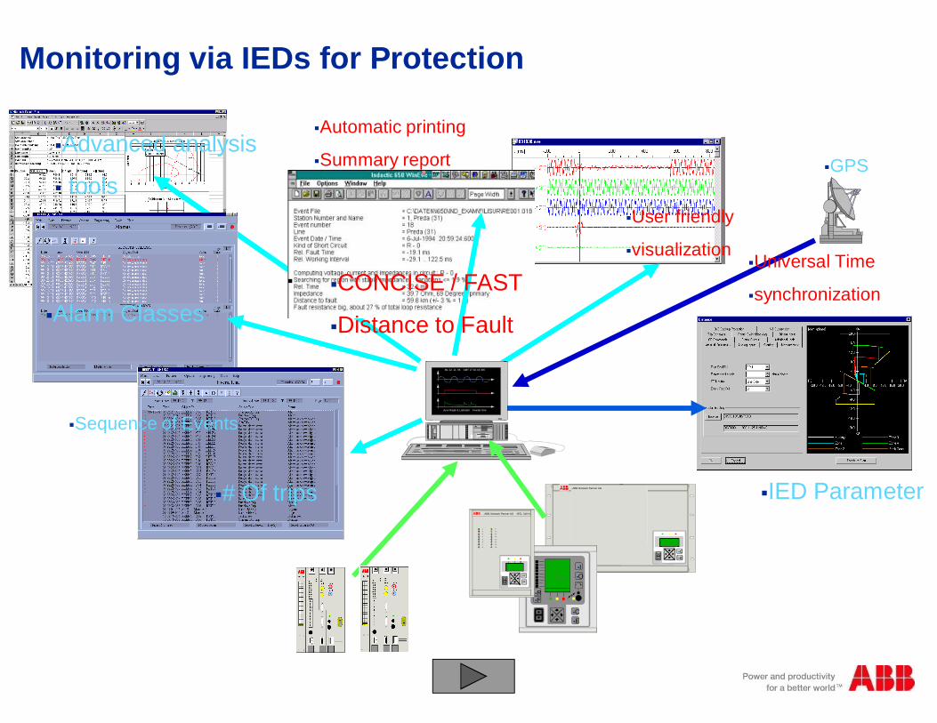
§Advanced analysis
§ tools
§Alarm Classes
§GPS
§Universal Time
§synchronization
§User friendly
§visualization
§# Of trips
§Sequence of Events
§Automatic printing
§Summary report
§CONCISE / FAST
§Distance to Fault
§IED Parameter§ABB Network Partner AG
§C§E
§Mo 12. 11. 96 GMT 17:02.43.305
§Ay er Rajah & Labrador Feeder One
§Bay
§C§E
§R§F
§I§O
§1
§2
§3
§4
§5
§6
§7
§8
§9
§10
§11
§12
§13
§14
§15
§16
§ABB Network Partner AG §REL 316*4
§C
§E
Monitoring via IEDs for Protection
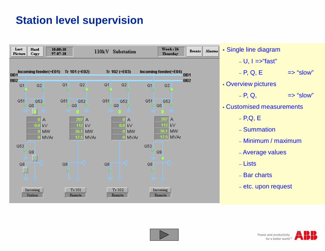
• Single line diagram
– U, I =>”fast”
– P, Q, E => “slow”
• Overview pictures
– P, Q, => “slow”
• Customised measurements
– P,Q, E
– Summation
– Minimum / maximum
– Average values
– Lists
– Bar charts
– etc. upon request
Station level supervision
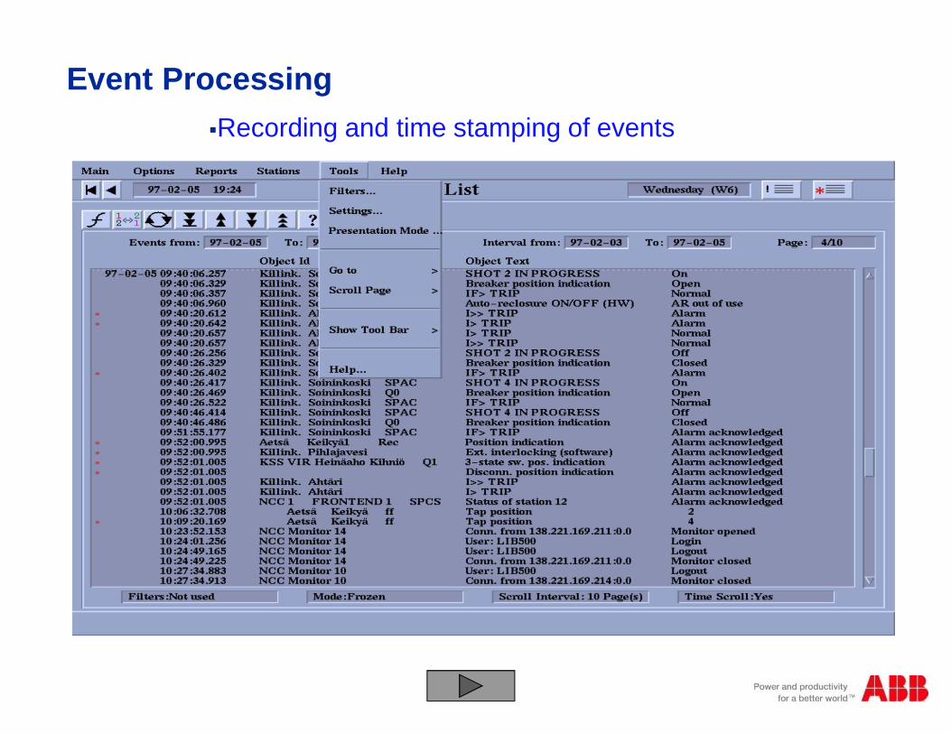
§Recording and time stamping of events
Event Processing
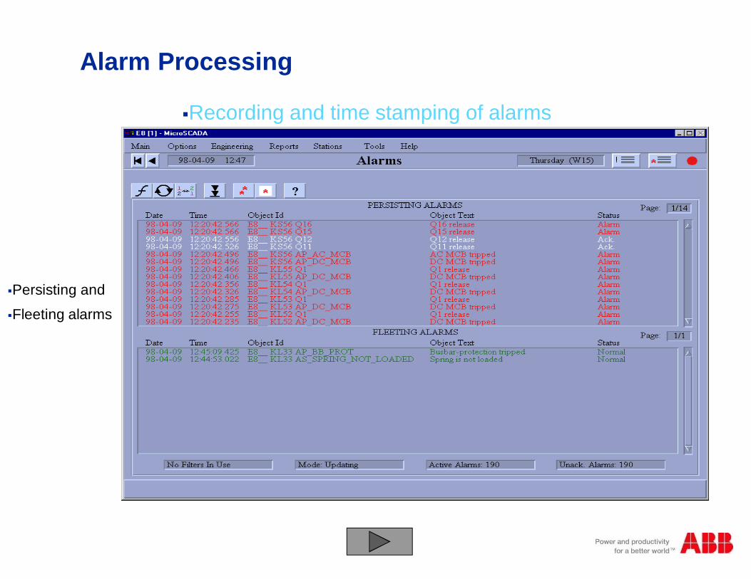
Alarm Processing
§Persisting and
§Fleeting alarms
§Recording and time stamping of alarms
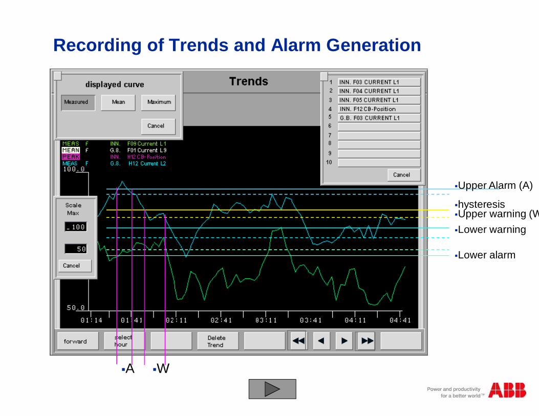
Recording of Trends and Alarm Generation
§Upper Alarm (A)
§hysteresis§Upper warning (W)§Lower warning
§Lower alarm
§A §W
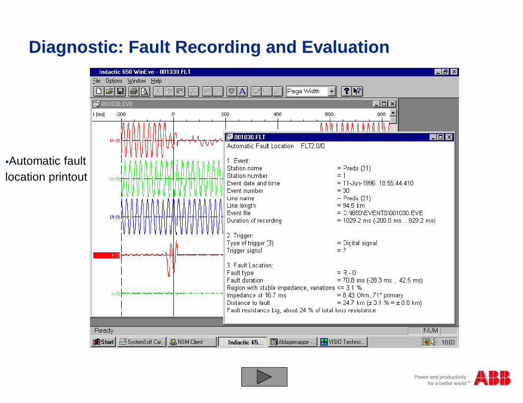
Diagnostic: Fault Recording and Evaluation
§Automatic faultlocation printout

SAS-Expectation
Data Exchange in a Substation Automation System
§ Monitored Information
1. Alarms
2. Status of switching devices
3. Step position indication (Transformer tap position)
4. Analog measurements (voltages, currents, power, etc.,)
5. Pulse counter data (kWH, kVARH,etc.,)
6. Protection Events
7. Disturbance records
8. IED configuration data
§© ABB Group§November 10, 2014 | Slide 35
Data Exchange in a Substation Automation System
§ Control Information
§ Close or trip commands§ Regulating step command§ Parameter setting command
§ Exchange of Information between devices throughGOOSE
§© ABB Group§November 10, 2014 | Slide 36
Communication in Substation Automation:

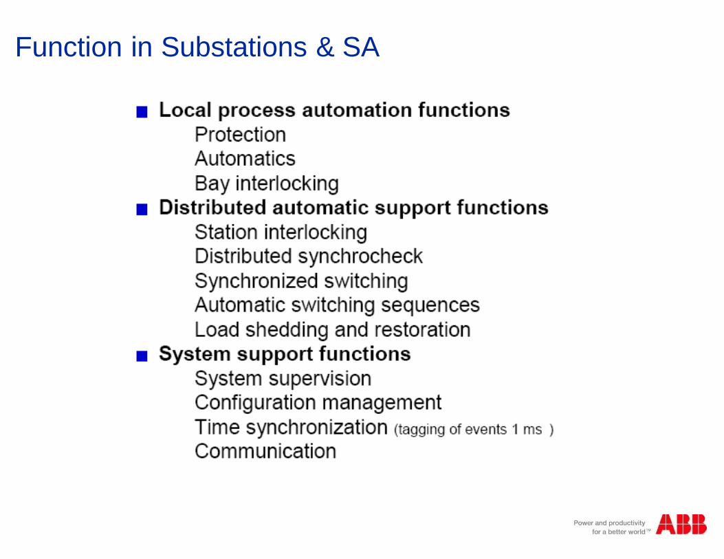
Function in Substations & SA
Function in Substations & SA

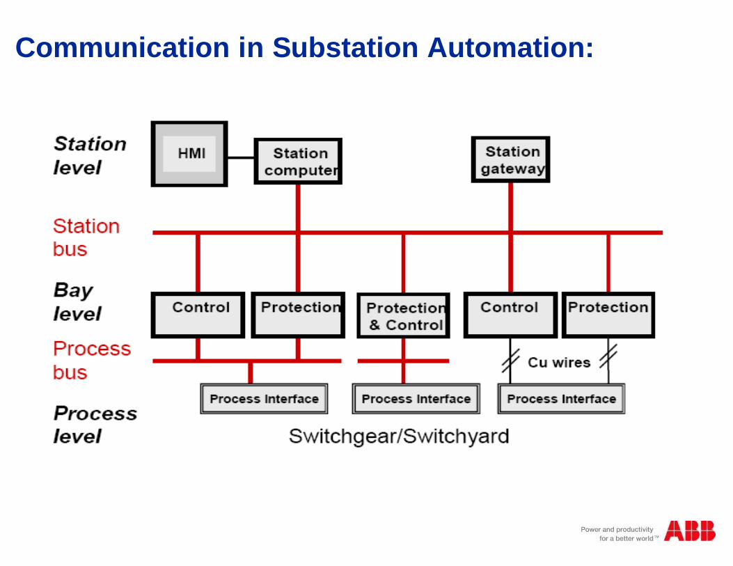
§Today a substation automation system comprises three hierarchical levels,
• the station level
• the bay level
• the process level
§The communication between station level and bay level is realized by means ofdifferent incompatible protocols such as IEC 60870, Profibus, DNP, LON, Modbusand many of other proprietary and non-proprietary ones.
§Parallel wiring is mostly used for the communication between the bay level and theprocess level.
IEC 61850 – Communication Networks & Systems inS/S
§© ABB Group§November 10, 2014 | Slide 40

The conventional way
§MARSHALING RACK
§TELE- §ALARMING§NISATION
§BUSBAR§PROTECTION
§Local
§Control
§Inter-
§locking§Measuring
§Bay
§Protection
§Telecontrol
§RTU§Alarming
§Synchro-
§nization
§Busbar
§Protection
§Control Board
§© ABB Group§November 10, 2014 | Slide 41

The new way
§LAN/WAN
§TCP/IP
§Async protocols
§LON
§. . . . .
§GW
§E
§C
§RE. 5XX
§ABB
§REC 561
§E
§C
§E
§C
§RE. 5XX§REC 561
§E
§C
§© ABB Group§November 10, 2014 | Slide 42

§ 100 – series
§ 200 – series
§ 300 – series
§ 500 – series
+ Further enhanced algorithms
+ Further increased functionality
+ Further improved tools
+ New user friendly HMI
+ Full IEC61850 implementation
= Introducing IED670
ONE high performance IEDfor ALL transmission applications
The next step in our IED evolution
§© ABB Group
§November 10, 2014 | Slide 43

IED670 IN SUBSTATION AUTOMATION
§IED = Intelligent Electronic Device used forProtection & Control of the Power System
§IED670 = is the designation of a range of newIEDs for high end transmission & generationapplications utilizing common modularhardware and software for protection andcontrol
§REC670 = Single or multi bay
§REL670 = Lines & Cables
§RET670 = Transformers & Reactors
§RED670 = Multi terminal networks
§REB670 = Bus and breaker
§© ABB Group§November 10, 2014 | Slide 44

§Pro
cess
Leve
l§B
ayLe
vel
§Sta
tion
Leve
l
§GIS or AIS
§Switchgear
§-Q1
§-Q0 §-Q8§-Q9
§-Q2
§1
§3§8
§=D04+R01§225kV LIGNE ABOBO 1§ABB
§ 125VDC Distributuion Battery A §125VDC Distributuion Battery B
§Fault
§Recording§=D04+R01§225kV LIGNE ABOBO 1§ABB
§ 125VDC Distributuion Battery A §125VDC Distributuion Battery B
§BAY CONTROL RELAY REC316*4
§1§ABB
§2§4§3§5§6§7§8§9§12§11§13§14§15§16§10§LOCAL CONTROL § METERING
§LINE PROTECTION RELAY REL316*4
§1§ABB
§2§4§3§5§6§7§8§9§12§11§13§14§15§16§10§BUSBAR PROTECTION REB500
§ABB
§-Q1§1§2§3§4§5§6§7§8§9§10§11§12§13§14§15§16§c§c
§Bay Protection
§Local
§Control
§=D04+R01§225kV LIGNE ABOBO 1§ABB
§ 125VDC Distributuion Battery A §125VDC Distributuion Battery B
§Busbar Protection§SCADA
§RTU §=D04+R01§225kV LIGNE ABOBO 1§ABB
§ 125VDC Distributuion Battery A §125VDC Distributuion Battery B
§RTU 200§ IN 1§ IN 2§ IN 3§ IN 4§ IN 5§ IN 6§ IN 7§ IN 8§OUT
§ON/OFF
§RTU 200§ IN 1§ IN 2§ IN 3§ IN 4§ IN 5§ IN 6§ IN 7§ IN 8§OUT
§ON/OFF
§RTU 200§ IN 1§ IN 2§ IN 3§ IN 4§ IN 5§ IN 6§ IN 7 § IN 8§OUT
§ON/OFF
§=D04+R01§225kV LIGNE ABOBO 1§ABB
§ 125VDC Distributuion Battery A §125VDC Distributuion Battery B
§Event
§Recording
§BayControl
§=D04+R01§225kV LIGNE ABOBO 1§ABB
§ABB
§ -Q2§SEL
§ -Q1§SEL
§ -Q0§SEL
§=W1
§=W2
§FERMER§OUVRIR
§EXE§ESC
§LAMPE§TESTE
§DISTANCE§LOC
§ABB §ABB §ABB
§=D04+R01§225kV LIGNE ABOBO 1§ABB
§ABB
§ -Q2§SEL
§ -Q1§SEL
§ -Q0§SEL
§=W1
§=W2
§FERMER§OUVRIR
§EXE§ESC
§LAMPE§TESTE
§DISTANCE§LOC
§ABB §ABB §ABB
Conventional Control & Protection
§© ABB Group§November 10, 2014 | Slide 45
§Pro
cess
Leve
l§B
ayLe
vel
§Sta
tion
Leve
l
§GIS or AIS
§Switchgear
§-Q1
§-Q0 §-Q8§-Q9
§-Q2
§1
§3§8
§=D04+R01§225kV LIGNE ABOBO 1§ABB
§ 125VDC Distributuion Battery A §125VDC Distributuion Battery B
§Fault
§Recording§=D04+R01§225kV LIGNE ABOBO 1§ABB
§ 125VDC Distributuion Battery A §125VDC Distributuion Battery B
§BAY CONTROL RELAY REC316*4
§1§ABB
§2§4§3§5§6§7§8§9§12§11§13§14§15§16§10§LOCAL CONTROL § METERING
§LINE PROTECTION RELAY REL316*4
§1§ABB
§2§4§3§5§6§7§8§9§12§11§13§14§15§16§10§BUSBAR PROTECTION REB500
§ABB
§-Q1§1§2§3§4§5§6§7§8§9§10§11§12§13§14§15§16§c§c
§Bay Protection
§Local
§Control
§=D04+R01§225kV LIGNE ABOBO 1§ABB
§ 125VDC Distributuion Battery A §125VDC Distributuion Battery B
§Busbar Protection§SCADA
§RTU §=D04+R01§225kV LIGNE ABOBO 1§ABB
§ 125VDC Distributuion Battery A §125VDC Distributuion Battery B
§RTU 200§ IN 1§ IN 2§ IN 3§ IN 4§ IN 5§ IN 6§ IN 7§ IN 8§OUT
§ON/OFF
§RTU 200§ IN 1§ IN 2§ IN 3§ IN 4§ IN 5§ IN 6§ IN 7§ IN 8§OUT
§ON/OFF
§RTU 200§ IN 1§ IN 2§ IN 3§ IN 4§ IN 5§ IN 6§ IN 7 § IN 8§OUT
§ON/OFF
§=D04+R01§225kV LIGNE ABOBO 1§ABB
§ 125VDC Distributuion Battery A §125VDC Distributuion Battery B
§Event
§Recording§Bay
Control §=D04+R01§225kV LIGNE ABOBO 1§ABB
§ABB
§ -Q2§SEL
§ -Q1§SEL
§ -Q0§SEL
§=W1
§=W2
§FERMER§OUVRIR
§EXE§ESC
§LAMPE§TESTE
§DISTANCE§LOC
§ABB §ABB §ABB
§=D04+R01§225kV LIGNE ABOBO 1§ABB
§ABB
§ -Q2§SEL
§ -Q1§SEL
§ -Q0§SEL
§=W1
§=W2
§FERMER§OUVRIR
§EXE§ESC
§LAMPE§TESTE
§DISTANCE§LOC
§ABB §ABB §ABB
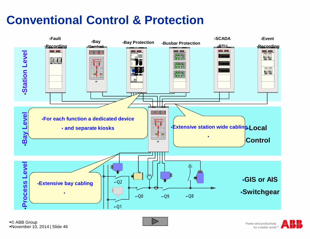
§For each function a dedicated device
§ and separate kiosks §Extensive station wide cabling
§
§Extensive bay cabling
§
Conventional Control & Protection
§© ABB Group§November 10, 2014 | Slide 46
§-Q1
§-Q0 §-Q8§-Q9
§-Q2
=D04+R01225kV LIG NE ABO BO 1ABB
125VDC Distributuion Battery A 125VDC Distributuion Battery B
BAY CONTROL RELAY REC316*4
1
ABBA B B N e tw o r k P a r tn e r
REL 3 1 6 * 4
243
5678
9
1 21 1
1 31 41 51 6
1 0
LOCAL CONTROL METERING
LINE PROTECTION RELAY REL316*4
1
ABBA B B N e tw o r k P a r tn e r
REL 3 1 6 * 4
2
43
5678
9
1 21 1
1 31 41 51 6
1 0
BUSBAR PROTECTION REB500
ABB A B B N e tw o r k P a r tn e r REB5 0 0
ABB
=D04 ABOBO 1
- Q2SEL
- Q1SEL
- Q0SEL
= W 1
= W 2
F E R ME ROU V R IR
E X EE S C
L A MP ET E S T E
DIS T A NCE
L OC
ABBPOW ER MONIT ORING UNIT
§Pro
cess
Leve
l§B
ayLe
vel
§Sta
tion
Leve
l
§ABB Network Partner AG
§C
§E
§COM581
§Network Control
§Center NCC
§Inter Bay Bus (Proprietary)
Modern SA Architecture
§© ABB Group§November 10, 2014 | Slide 47
§ABB Network Partner AG
§C
§E
§COM581
§Network Control
§Center NCC
§PIS
A
§PIS
A§A
§PIS
A§B
§PIS
A§A
§-Q1
§-Q2
§-Q51
§-Q0 §-T1 §-Q9 §-Q8
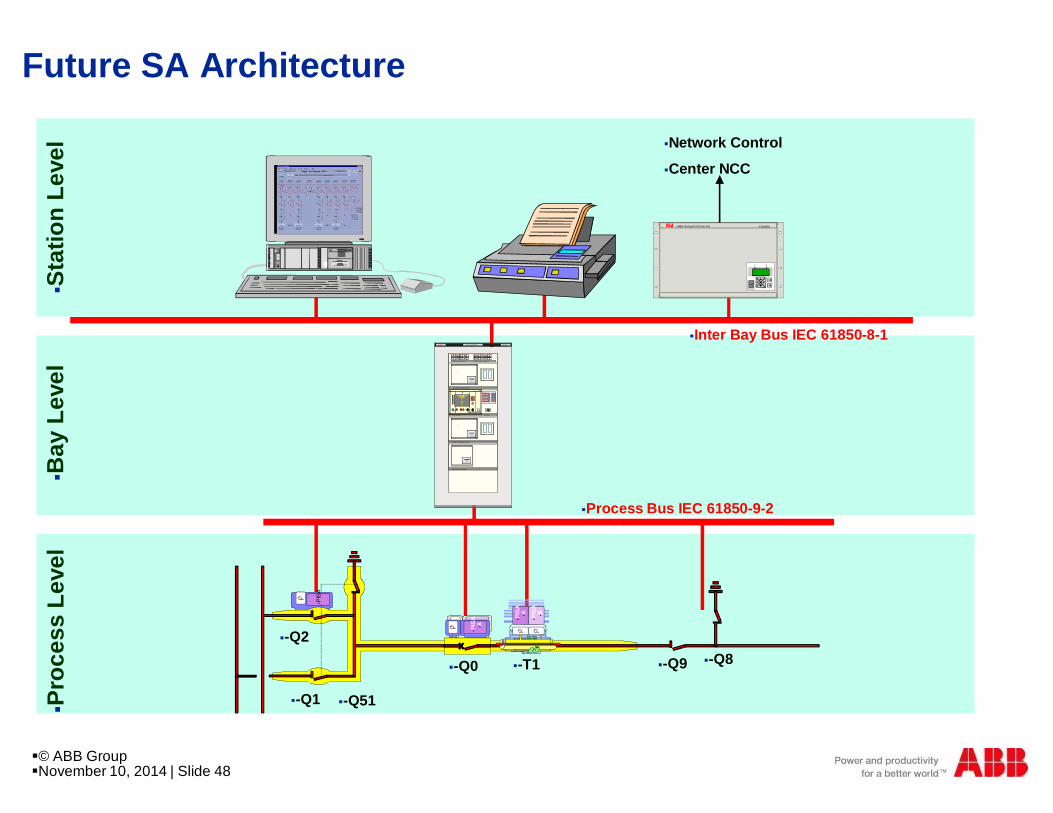
§Pro
cess
Leve
l
=D04+R01225kV LIG NE ABO BO 1ABB
125VDC Distributuion Battery A 125VDC Distributuion Battery B
BAY CONTROL RELAY REC316*4
1
ABBA B B N e tw o r k P a r tn e r
REL 3 1 6 * 4
2
43
5678
9
1 21 1
1 31 41 51 6
1 0
LOCAL CONTROL METERING
LINE PROTECTION RELAY REL316*4
1
ABBA B B N e tw o r k P a r tn e r
REL 3 1 6 * 4
2
43
5678
9
1 21 1
1 31 41 51 6
1 0
BUSBAR PROTECTION REB500
ABBA B B N e tw o r k P a r tn e r REB5 0 0
ABB
=D04 ABOBO 1
- Q2SEL
- Q1SEL
- Q0SEL
= W 1
= W 2
F E R ME RO U V R IR
E X EE S C
L A MP ET E S T E
DIS T A NCE
L OC
ABBPOW ER MONIT ORING UNIT
§? §LOCAL§REMOTE
§SET§OPERATION
§M
§M
§M
§Bay
Leve
l§S
tatio
nLe
vel
§Process Bus IEC 61850-9-2
§Inter Bay Bus IEC 61850-8-1
Future SA Architecture
§© ABB Group§November 10, 2014 | Slide 48

WHAT IS A PROTOCOL?
Protocol:
§ Set of rules that determines the behavior of functionalunits in achieving and performing communication.
Open Protocol:
§ A communication protocol whose stack is eitherstandardized or publicly available.

Up to now: different protocols used
§© ABB Group§November 10, 2014 | Slide 50

StationAutomation
StationAutomation
Control Center Control Center
SPA, LON, DNP 3.0, MODBUS, UCA 2, Profibus, IEC60 870-5-103, K-Bus, ZZZ
IEC60870-6 (TASE2)
SCADAIEC60870-5-101IEC60870-5-104DNP 3.0ELCOM 90RP570/571XXX
Metering & BillingIEC61107IEC62056IEC60870-5-102YYY
WindfarmsIEC51400-25
IEC G703IEEE C37.94WWW
IEC 61850
IEC 61850
= IEC 61850
IEC61970 (CIM)
With a number of communication protocols

Towards a Global Solution for...
“A solid background creates stronginnovations”
...Substation AutomationSystems
Experience in:§ International standards
§ De facto standards
§ Customer requirements
§ Proprietary solutions
§ System engineering
Goals:§ Interoperability
§ Future-proof standard
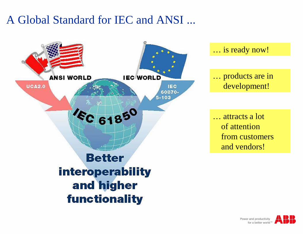
… is ready now!
… products are indevelopment!
… attracts a lotof attentionfrom customersand vendors!
A Global Standard for IEC and ANSI ...
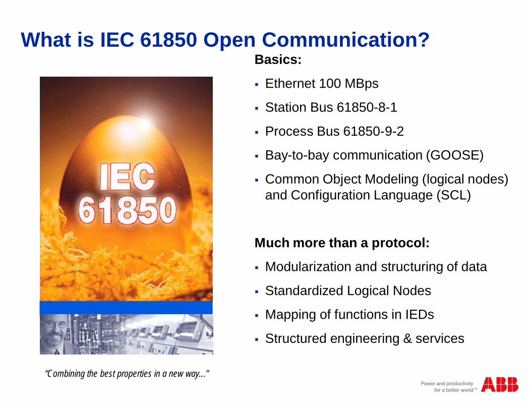
Basics:
§ Ethernet 100 MBps
§ Station Bus 61850-8-1
§ Process Bus 61850-9-2
§ Bay-to-bay communication (GOOSE)
§ Common Object Modeling (logical nodes)and Configuration Language (SCL)
Much more than a protocol:
§ Modularization and structuring of data
§ Standardized Logical Nodes
§ Mapping of functions in IEDs
§ Structured engineering & services
“Combining the best properties in a new way...”
What is IEC 61850 Open Communication?
A Breakthrough for Substation Automation
“Combining the best properties in a newway...”
§ One world
§ One technology
§ One standard
IEC 61850
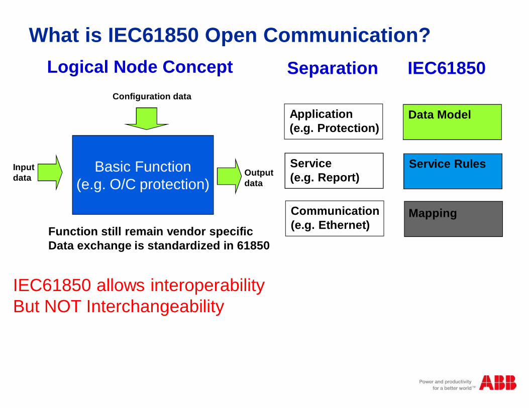
What is IEC61850 Open Communication?
IEC61850 allows interoperabilityBut NOT Interchangeability
Basic Function(e.g. O/C protection)
Configuration data
Inputdata Output
data
Function still remain vendor specificData exchange is standardized in 61850
Logical Node Concept Separation IEC61850
Application(e.g. Protection)
Service(e.g. Report)
Communication(e.g. Ethernet)
Data Model
Service Rules
Mapping

IEC 61850 Time scale
§© ABB Group§November 10, 2014 | Slide 57

Up to now: different protocols used
§IEC 61850
§© ABB Group§November 10, 2014 | Slide 58
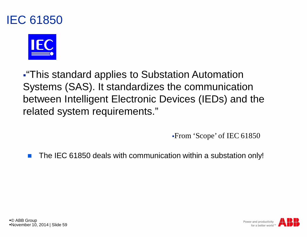
IEC 61850
n The IEC 61850 deals with communication within a substation only!
§“This standard applies to Substation AutomationSystems (SAS). It standardizes the communicationbetween Intelligent Electronic Devices (IEDs) and therelated system requirements.”
§From ‘Scope’ of IEC 61850
§© ABB Group§November 10, 2014 | Slide 59
IEC 61850 a breakthrough for SA
§“Combining the best properties in a new way...”
§ IEC 61850 is a global standardfor “Communication Networksand Systems in Substations”
n One world
n One technology
n One standard
§© ABB Group
§November 10, 2014 | Slide 60
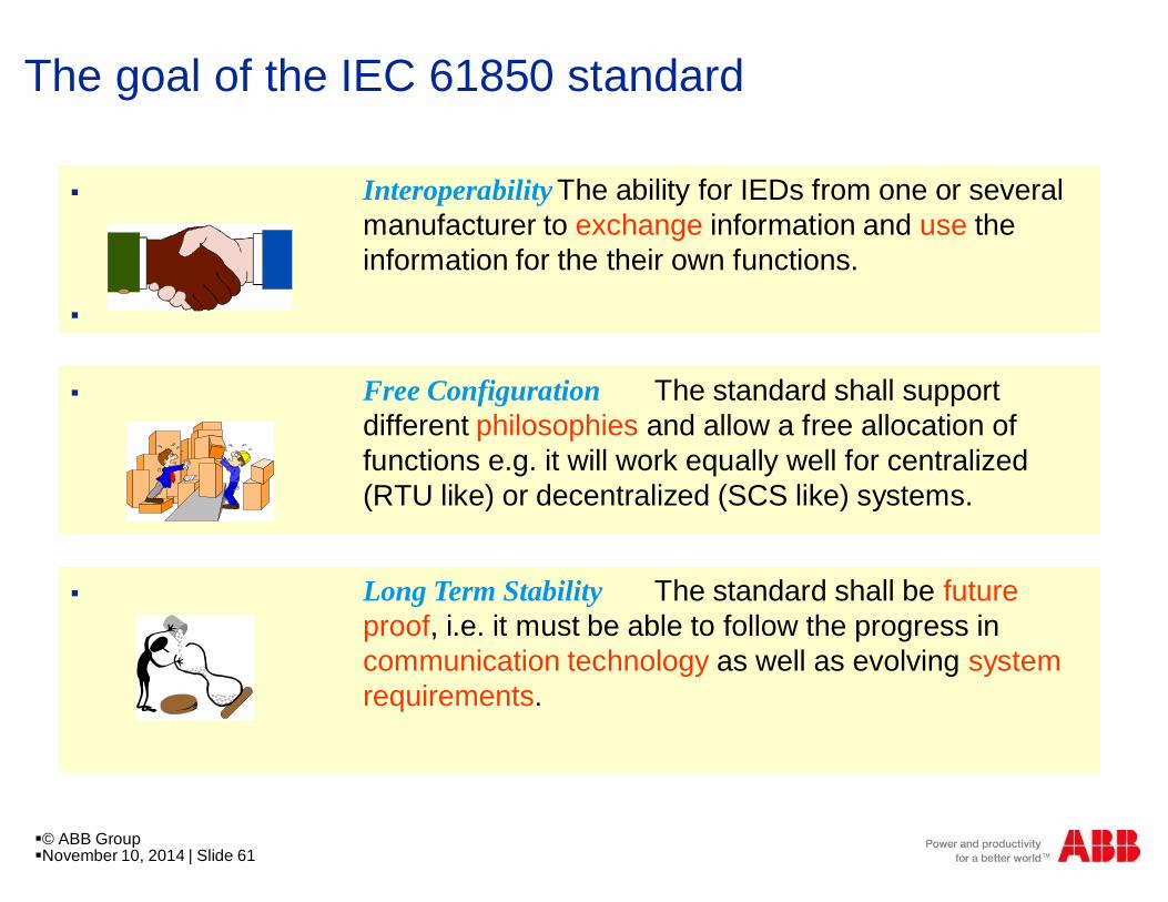
The goal of the IEC 61850 standard
§ Interoperability The ability for IEDs from one or severalmanufacturer to exchange information and use theinformation for the their own functions.
§
§ Free Configuration The standard shall supportdifferent philosophies and allow a free allocation offunctions e.g. it will work equally well for centralized(RTU like) or decentralized (SCS like) systems.
§ Long Term Stability The standard shall be futureproof, i.e. it must be able to follow the progress incommunication technology as well as evolving systemrequirements.
§© ABB Group§November 10, 2014 | Slide 61
The New Standard for Intelligent Investment
Savings from efficient IED engineering
n IEDs are engineered using manufacturer specific IEDconfiguration tools
n Configuration tools translate the IED capabilities to the SCL(Substation Configuration description Language)
n SCL enables information exchange between IEDconfiguration tools from different manufacturers
n SCL secures backwards compatibility between differentversions of IEDs and IED configuration tools
§© ABB Group§November 10, 2014 | Slide 62
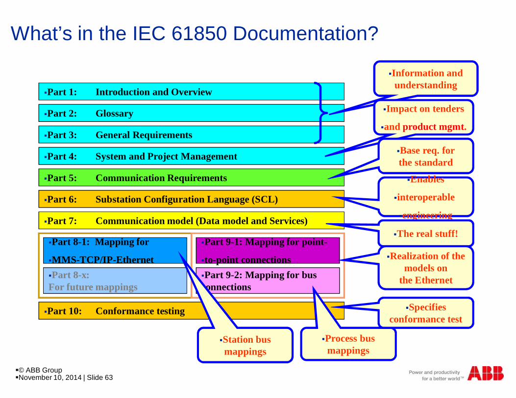
What’s in the IEC 61850 Documentation?
§Part 1: Introduction and Overview
§Part 2: Glossary
§Part 3: General Requirements
§Part 4: System and Project Management
§Part 5: Communication Requirements
§Part 7: Communication model (Data model and Services)
§Part 6: Substation Configuration Language (SCL)
§Part 10: Conformance testing
§Part 8-1: Mapping for
§MMS-TCP/IP-Ethernet§Part 8-x:For future mappings
§Part 9-1: Mapping for point-
§to-point connections§Part 9-2: Mapping for busconnections
§Process busmappings
§Information andunderstanding
§Impact on tenders
§and product mgmt.
§Base req. forthe standard
§Enables
§interoperable
§engineering
§The real stuff!
§Realization of themodels on
the Ethernet
§Station busmappings
§Specifiesconformance test
§© ABB Group§November 10, 2014 | Slide 63
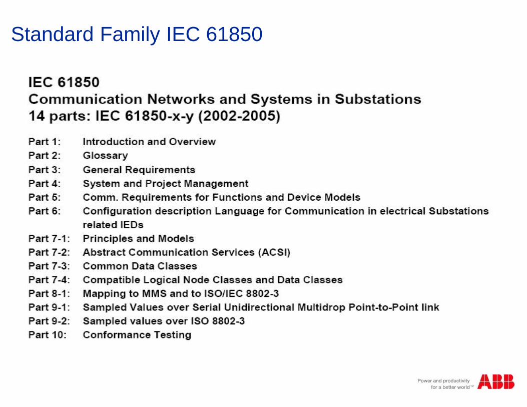
Standard Family IEC 61850

User-near, object oriented Data model

What Is Not Included in the IEC 61850?
n Product functions are notstandardized and not included
n Operator functions and operatorinterfaces are not standardizedand not included
n Products from different vendorsare interoperablebut not necessarilyinterchangeable
§Competitionremains …
§© ABB Group§November 10, 2014 | Slide 66

A Standard for Open Communications
Connecting:
n Devices from different suppliersn Engineering information from different
tools from different manufacturers
n Present and future installations
n New communication technologieswith existing applications
n Different and changing SAarchitectures
§© ABB Group§November 10, 2014 | Slide 67

What is IEC61850 Open Communication?
§IEC61850 allows interoperability
§But NOT Interchangeability
§Basic Function
§(e.g. O/C protection)
§Configuration data
§Input
§data§Output
§data
§Function still remain vendor specific
§Data exchange is standardized in 61850
§Logical Node Concept §Separation IEC61850
§Application
§(e.g. Protection)
§Service
§(e.g. Report)
§Communication
§(e.g. Ethernet)
§Data Model
§Service Rules
§Mapping
§© ABB Group§November 10, 2014 | Slide 68

Introduction of Logical nodes: Functional view

Naming and Groups of Logical Node (First letter listed)

Logical Nodes
Indicator Logical node groups QtyL System Logical Node 3
P Protection Functions 28
R Protection Related Functions 10
C Supervisory control 5
G Generic Function References 3
I Interface and Archiving 4
A Automatic control 4
M Metering and Measurement 8
S Sensors, Monitoring 4
X Switchgear 2
T Instrument Transformer 2
Y Power Transformer 4
Z Further (power system)equipment
5
- PDIR Directional Comparison
- PDIS Distance
- PSCH Protection scheme
- PTOC Time overcurrent
- PTOV Overvoltage
- more…
- MMXU Measuring (Measurand unit)
- MMTR Metering
- MSQI Sequence and imbalance
- MHAI Harmonics and inter-harmonics
- more …..- XCBR Circuit breaker
- XSWI Circuit switch
- RDIR Directional element
- RDRE Disturbance recorder function
- RBRF Breaker failure
- RFLO Fault locator
- RREC Autoreclosing
- more…
§© ABB Group§November 10, 2014 | Slide 71

Logical Groupings
§© ABB Group§November 10, 2014 | Slide 72

Allocation of LNs to devices (IEDs)

Data Hierarchy
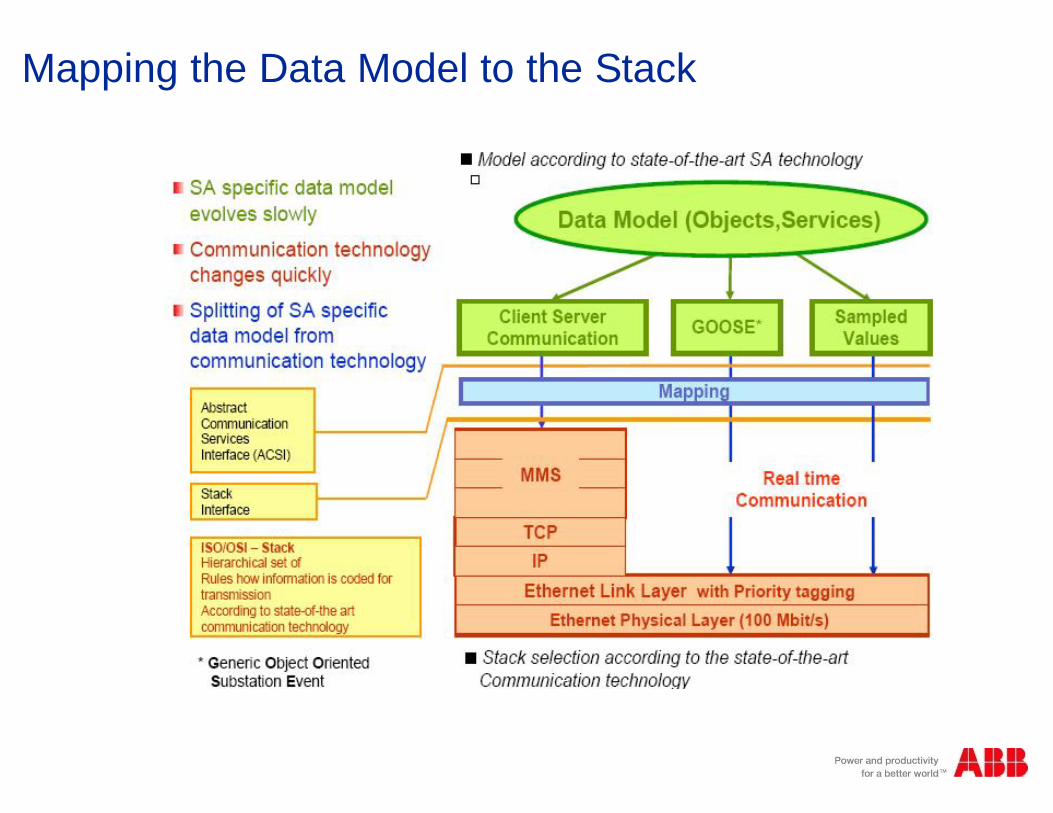
Mapping the Data Model to the Stack
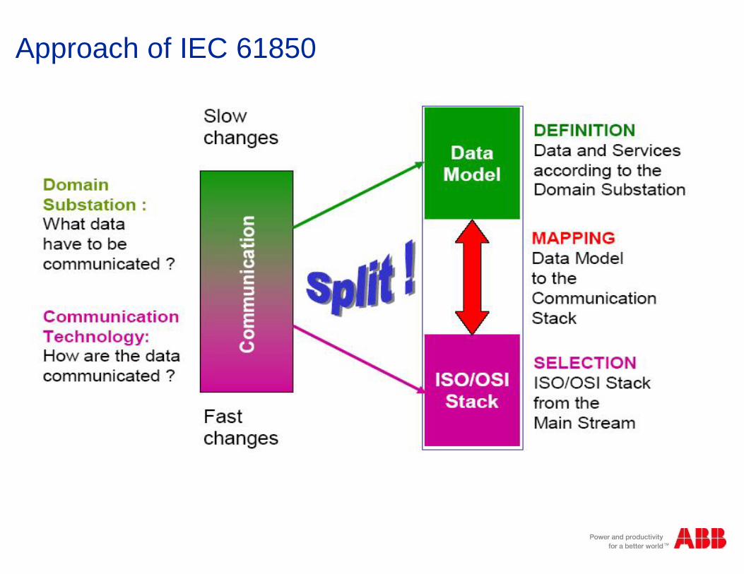
Approach of IEC 61850
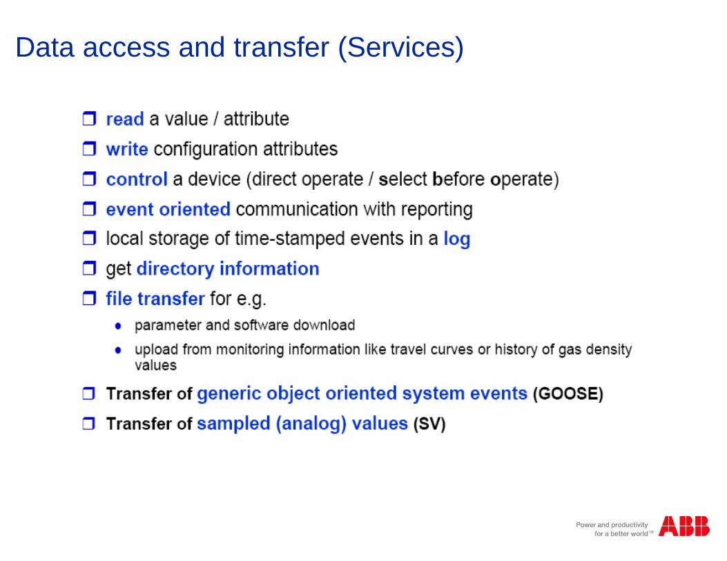
Data access and transfer (Services)
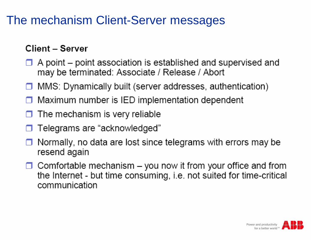
The mechanism Client-Server messages
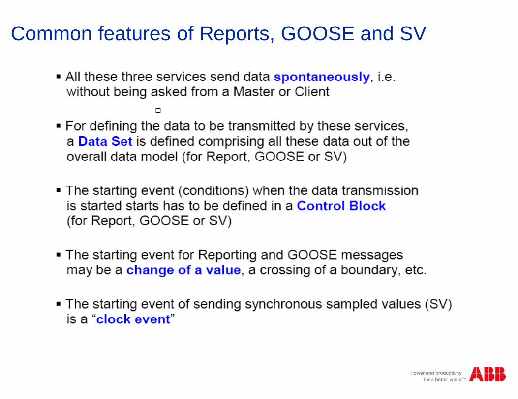
Common features of Reports, GOOSE and SV
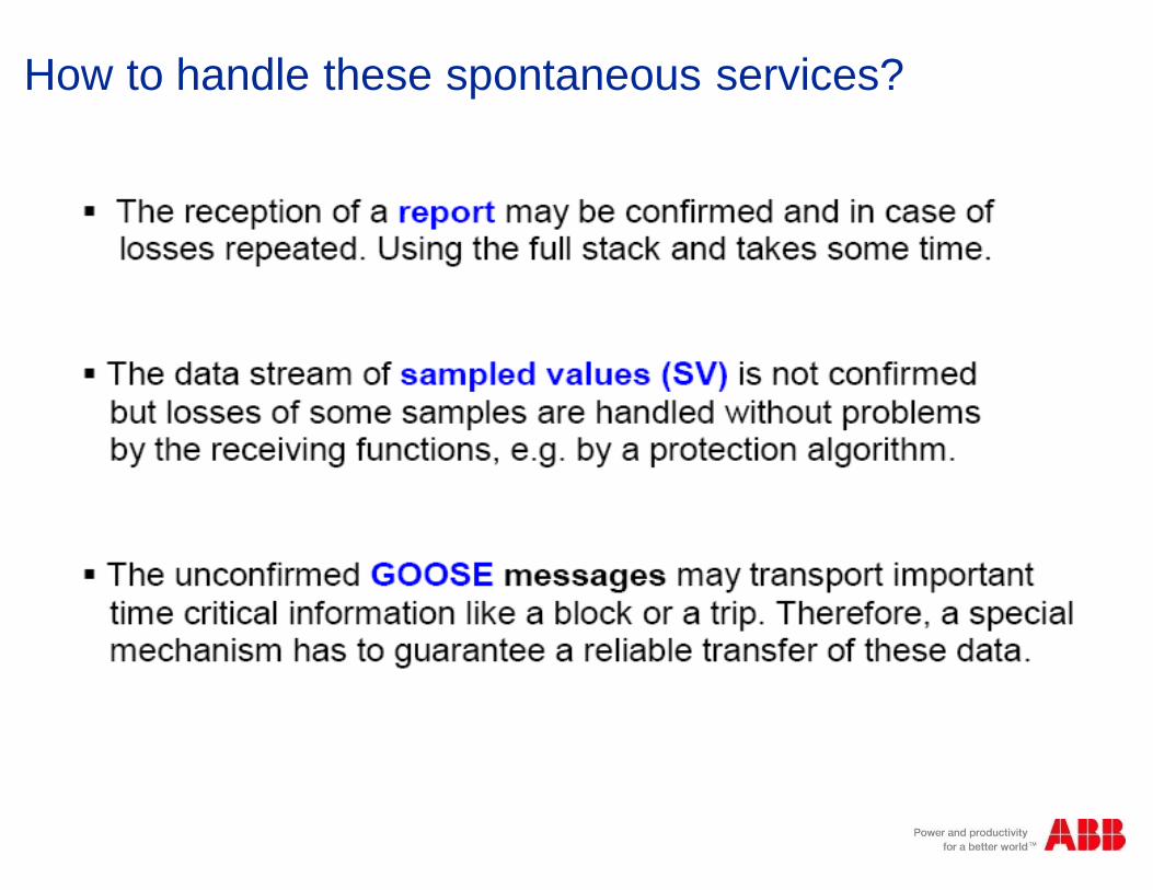
How to handle these spontaneous services?
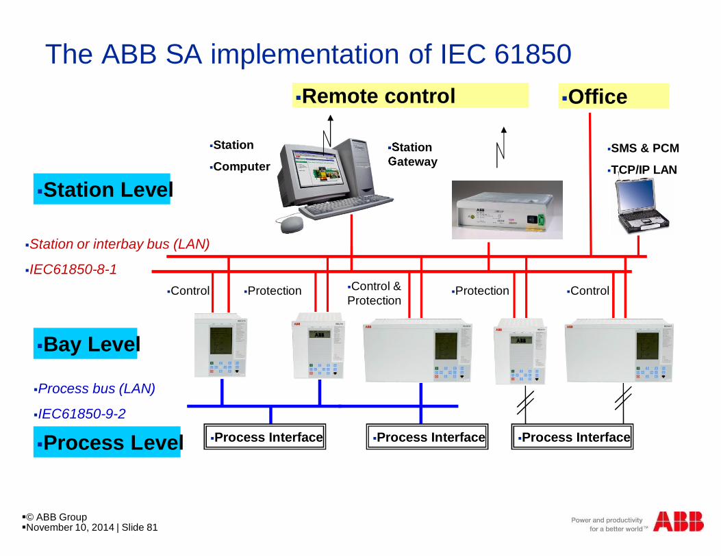
§Remote control
§Bay Level
§Process Level
§Station Level
§Station or interbay bus (LAN)
§IEC61850-8-1
§Process bus (LAN)
§IEC61850-9-2
§Station
§Computer§StationGateway
§Protection
§Process Interface
§Control§Protection§Control §Control &Protection
§Process Interface §Process Interface
§SMS & PCM
§TCP/IP LAN
§Office
The ABB SA implementation of IEC 61850
§© ABB Group§November 10, 2014 | Slide 81

IEC 61850 based SAS Architectures
§GPSReceiver
§REC 670 §REL 670 Main I§REC 670
§RET 670 Main I
§RET 670 Main II
§REC 670
§REB 500 Main I
§REB 500 Main II
§Busbar§Line x 2 §Autotransformer x 2 §Auxiliaries
§IEC 61850 Ring network
§IEC 60870-5-101/104
§Gateway
§DR WS §Redundant HMI
§Ethernet Switch§Ethernet Switch§Ethernet Switch
§Ethernet Switch§Ethernet Switch
§Laser Printer
§DMP
§REC 670
§Bus Coupl. x 1
§REL 670 Main II
§© ABB Group§November 10, 2014 | Slide 82
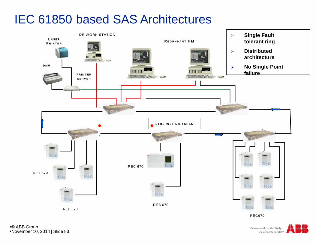
IEC 61850 based SAS ArchitecturesLASER
PRINTER
DMP
DR WORK STATION
REDUNDANT HMI
ETHERNET SWITCHES
PRINTERSERVER
RET 670
REL 670
REC 670
REB 670
REC670
Ø Single Faulttolerant ring
Ø Distributedarchitecture
Ø No Single Pointfailure
§© ABB Group§November 10, 2014 | Slide 83
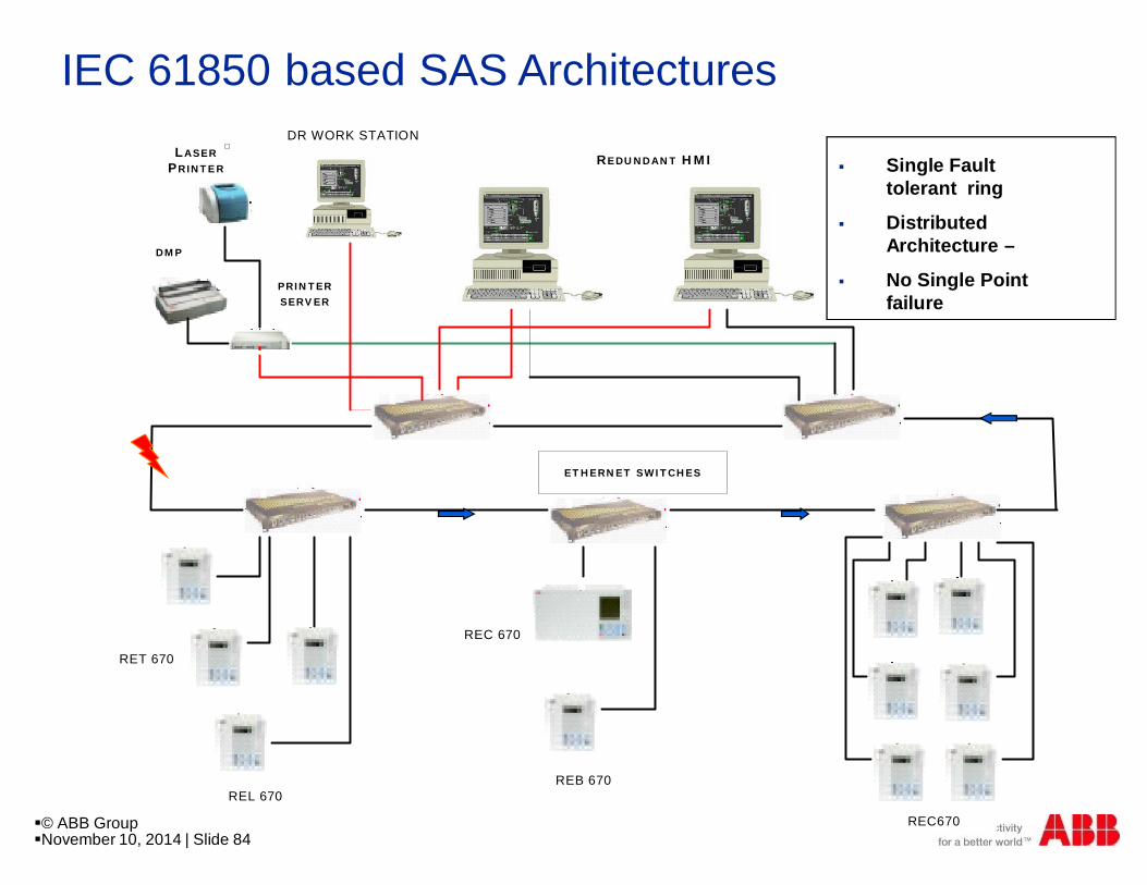
IEC 61850 based SAS ArchitecturesLASER
PRINTER
DMP
DR WORK STATION
REDUNDANT HMI
ETHERNET SWITCHES
PRINTERSERVER
RET 670
REL 670
REC 670
REB 670
REC670
§ Single Faulttolerant ring
§ DistributedArchitecture –
§ No Single Pointfailure
§© ABB Group§November 10, 2014 | Slide 84
Interoperability
§ Interoperability according to the 61850 standard means thecapability of two or more IEDs from the same or differentvendors to exchange information and to use it in theperformance of their functions.
§ It is much more than simple data transfer.
§© ABB Group§November 10, 2014 | Slide 85
Horizontal Communication
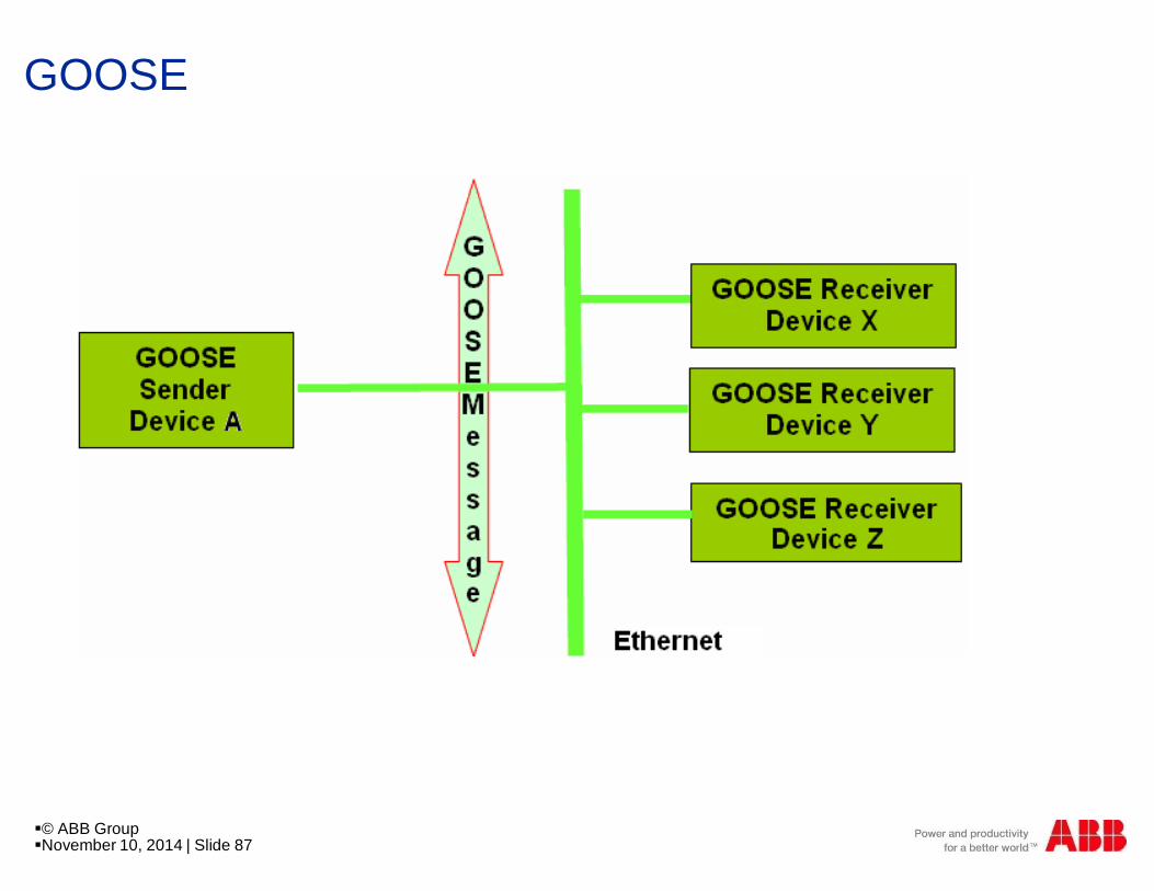
§ GOOSE stands for Generic Object Oriented SubstationEvent.
§ It is a mechanism for the fast transmission of substationevents, such as commands, alarms, indications, asmessages.
§ A GOOSE message sent by one IED can be received andused by several other IEDs.
§© ABB Group§November 10, 2014 | Slide 86
GOOSE
§© ABB Group§November 10, 2014 | Slide 87

Horizontal (peer-to-peer) communication
§Station
§computer
§Stationgateway
§Protection
§Process Interface §Process Interface §Process Interface
§Control§Protection§Control §Control &Protection
§GOOSE
§© ABB Group§November 10, 2014 | Slide 88

IEC 61850 GOOSE Priority tagging
n IEC 61850 uses standard Ethernet
n IEC 61850 can therefore take advantage from all the options of modernEthernet
n These options are not avilable in other protocols
§NormalTelegrams
§GOOSE
§Buffer for normaltelegrams
§Overtake lane for IECGOOSE
§Ethernet-Switch
§© ABB Group§November 10, 2014 | Slide 89
Vertical Communication
§ The HMI and gateways are IEC 61850 clients, while the IEDs are IEC 61850servers.
§ The communication between the servers and clients is usually by means ofreports.
§ IEC 61850 defines two types of reporting - buffered reports and unbufferedreports.
§© ABB Group§November 10, 2014 | Slide 90
Buffered Reports
§ Buffered reports are messages sent to specific clients, andhave to be acknowledged by the client.
§ If a client does not acknowledge the receipt of the messagethen the IED will retransmit the report to that client.
§ In ABB system we always use buffered reports for all IEDsthat support buffered reporting.
§© ABB Group§November 10, 2014 | Slide 91
Unbuffered Reports
§ Unbuffered reports are broadcast messages and clients donot acknowledge them.
§ Loss of data is not detected when unbuffered reports areused.
§© ABB Group§November 10, 2014 | Slide 92

Substation Configuration Language
§SCL
§SCL: Substation ConfigurationLanguage, is a formal descriptionof the communication in asubstation
§All communication related configurations are supported by one neutral andformal description. The description can serve as support for engineering andautomatic testing.
§© ABB Group§November 10, 2014 | Slide 93
IED Engineering
§IED Tool
§ICD-File
§Format: XML
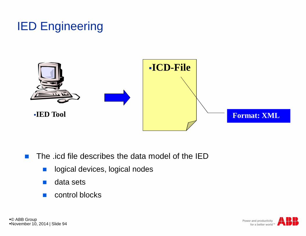
n The .icd file describes the data model of the IEDn logical devices, logical nodes
n data sets
n control blocks
§© ABB Group§November 10, 2014 | Slide 94
§ICD-File§ICD-File
§ICD-File
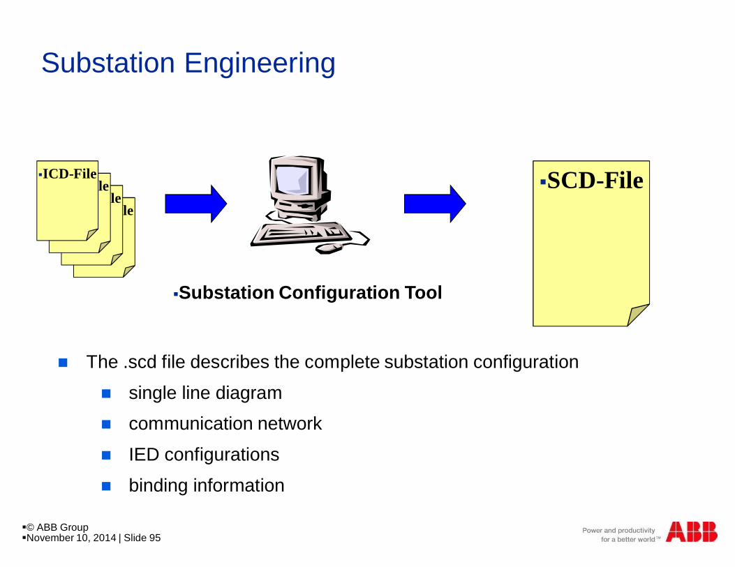
Substation Engineering
§ICD-File§SCD-File
§Substation Configuration Tool
n The .scd file describes the complete substation configuration
n single line diagramn communication network
n IED configurations
n binding information
§© ABB Group§November 10, 2014 | Slide 95
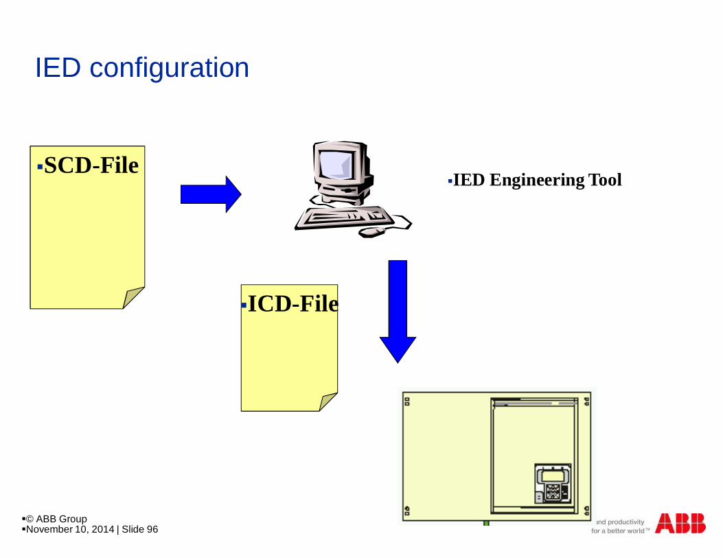
IED configuration
§ICD-File
§IED Engineering Tool§SCD-File
§© ABB Group§November 10, 2014 | Slide 96
© ABB GroupNovember 10, 2014 | Slide 97
Substation AutomationMicroSCADA Pro
Substation Automation system
Protection Parameter
Management
§Protection Parameter
§Management
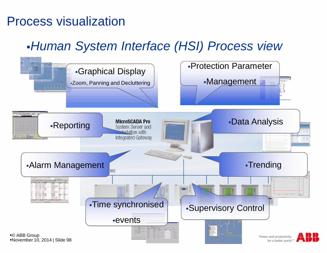
Process visualization
§Human System Interface (HSI) Process view
§Graphical Display§Zoom, Panning and Decluttering
§Trending
§Data Analysis
§Supervisory Control
§Alarm Management
§Time synchronised
§events
§Reporting
§© ABB Group§November 10, 2014 | Slide 98
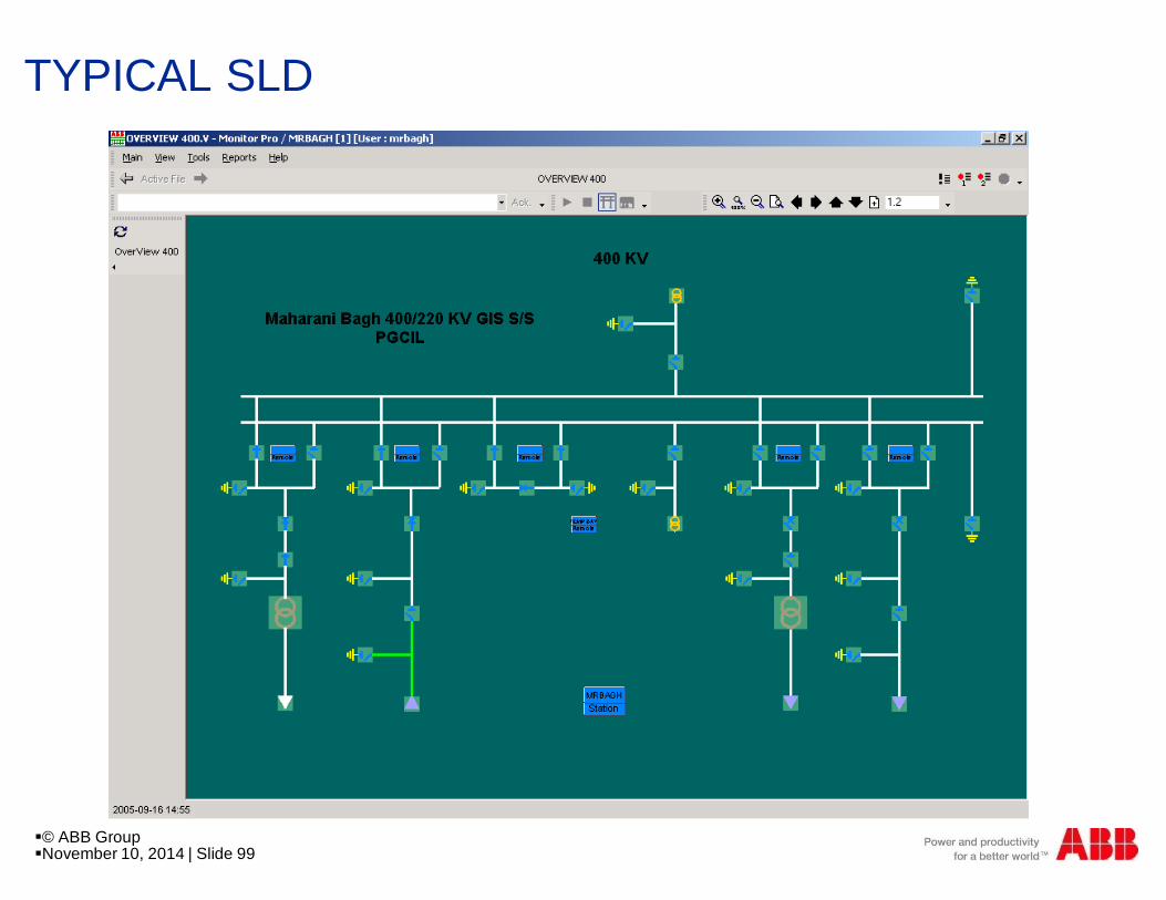
TYPICAL SLD
§© ABB Group§November 10, 2014 | Slide 99
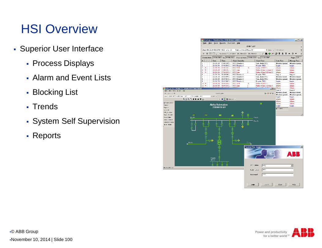
HSI Overview§ Superior User Interface
§ Process Displays
§ Alarm and Event Lists
§ Blocking List
§ Trends
§ System Self Supervision
§ Reports
§© ABB Group
§November 10, 2014 | Slide 100
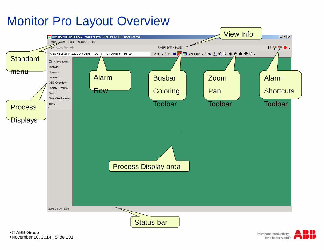
Monitor Pro Layout Overview
Status bar
Process Display area
Alarm
Shortcuts
Toolbar
Busbar
Coloring
ToolbarProcess
Displays
Alarm
Row
Zoom
Pan
Toolbar
View Info
Standard
menu
§© ABB Group§November 10, 2014 | Slide 101
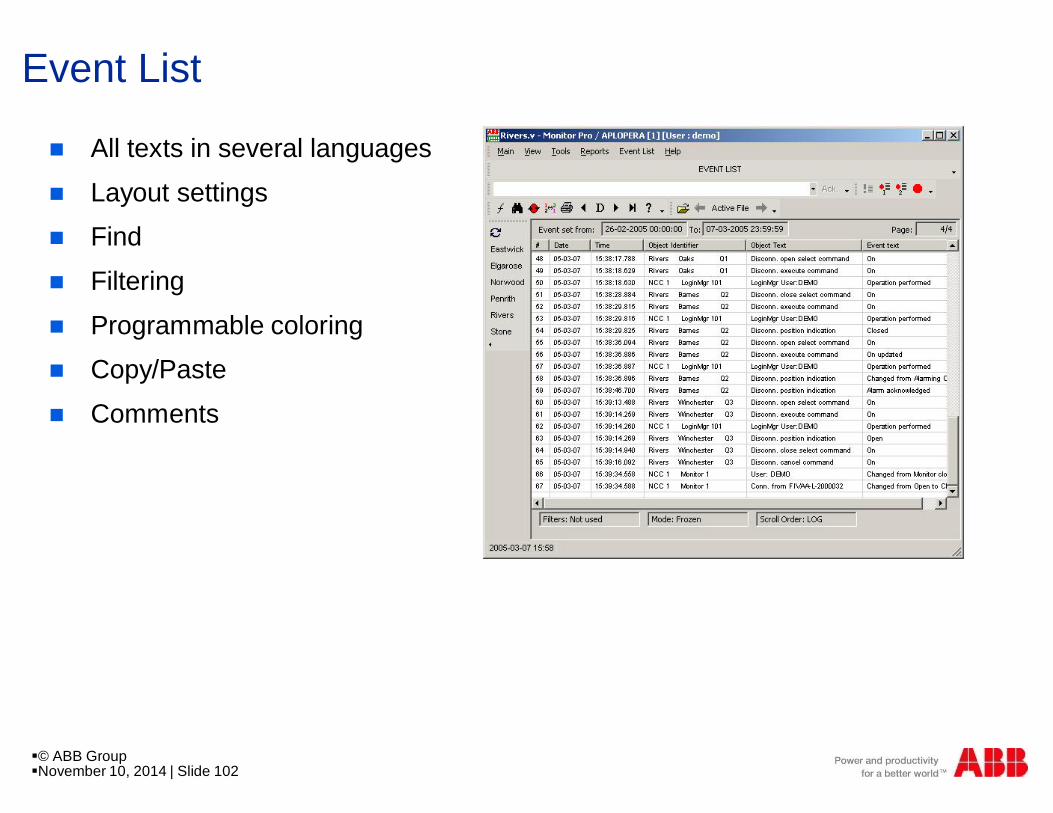
Event List
n All texts in several languages
n Layout settingsn Find
n Filtering
n Programmable coloringn Copy/Paste
n Comments
§© ABB Group§November 10, 2014 | Slide 102
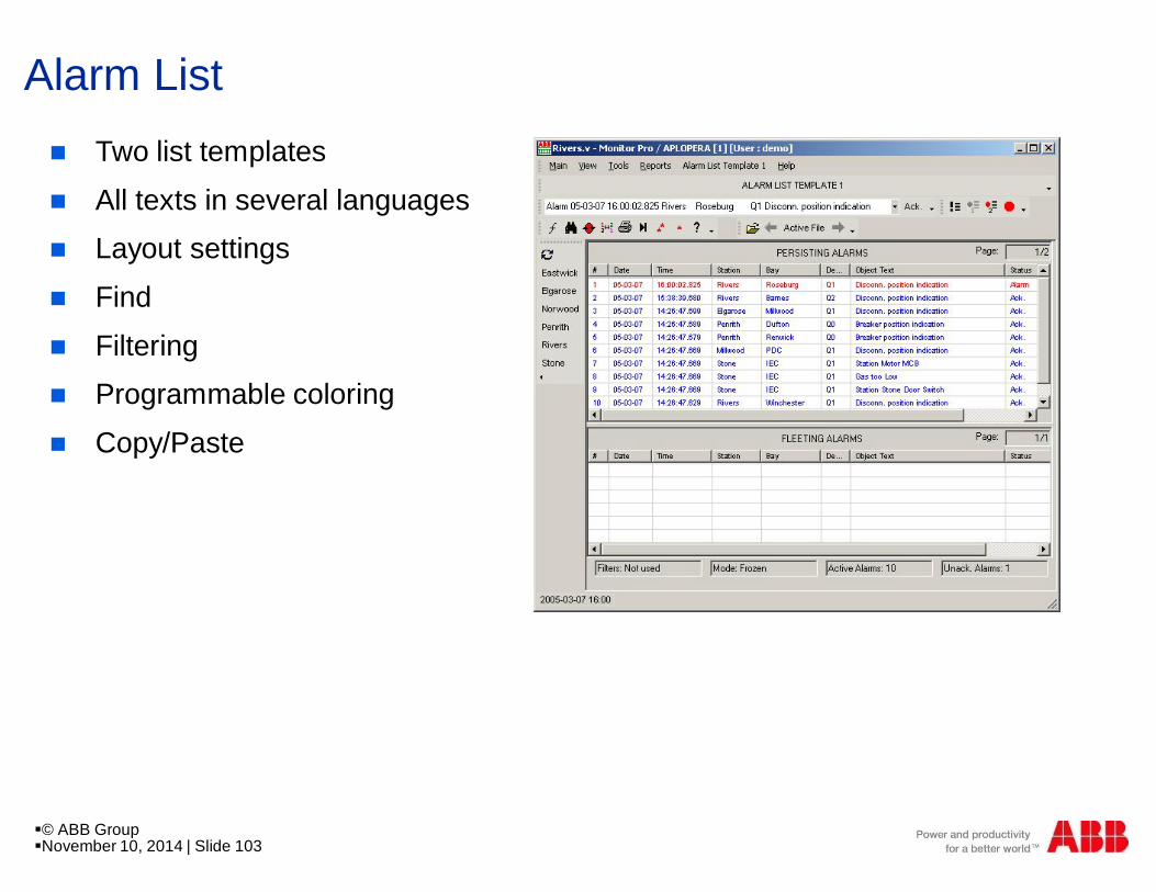
Alarm Listn Two list templates
n All texts in several languagesn Layout settings
n Find
n Filteringn Programmable coloring
n Copy/Paste
§© ABB Group§November 10, 2014 | Slide 103
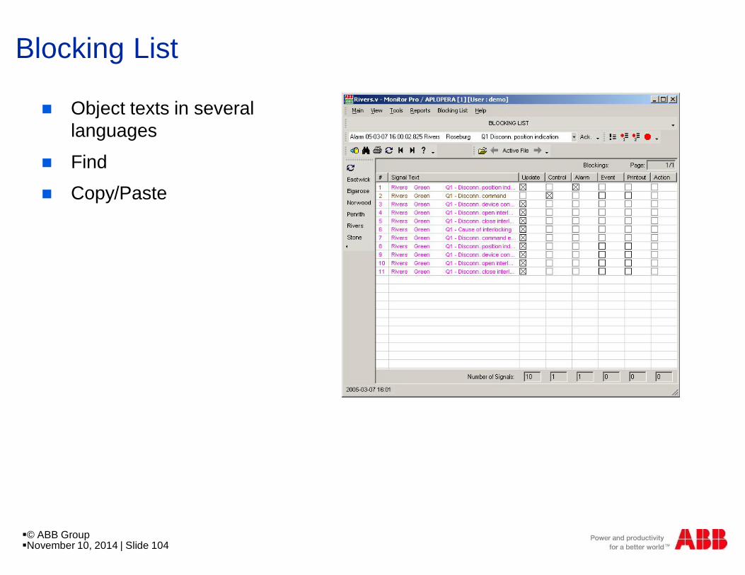
Blocking List
n Object texts in severallanguages
n Findn Copy/Paste
§© ABB Group§November 10, 2014 | Slide 104
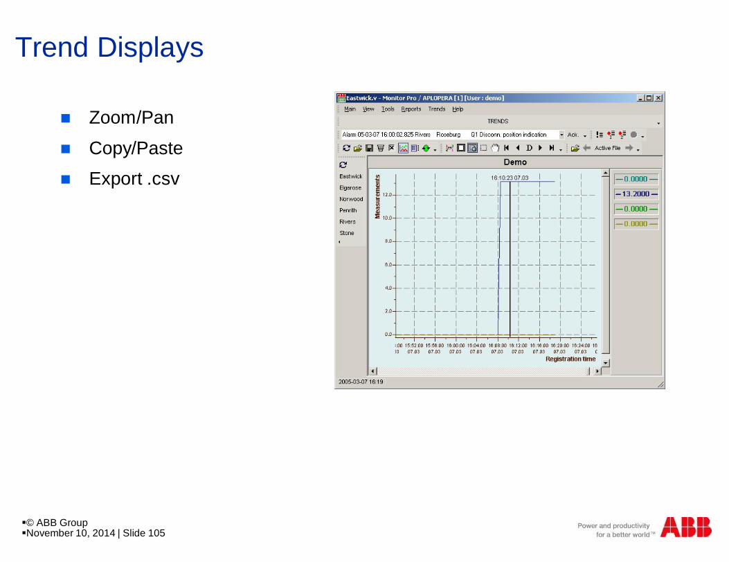
Trend Displays
n Zoom/Pan
n Copy/Pasten Export .csv
§© ABB Group§November 10, 2014 | Slide 105

Remote communication to “SCADA”n MicroSCADA Pro is designed to
communicate and connect toControl Centers
n Flexible gateway functionalityintegrated in HSI or asa stand alone gateway
Experience in:n International standards and De
facto standards
n IEC 60870 – 5 – 101n IEC 60870 – 5 – 104nDNP 3.0 SerialnDNP 3.0 TCP/IP
§© ABB Group§November 10, 2014 | Slide 106
§NCC
§Gateway
§MicroSCADA Pro
§COM 500*
§IEC 61850-8-1
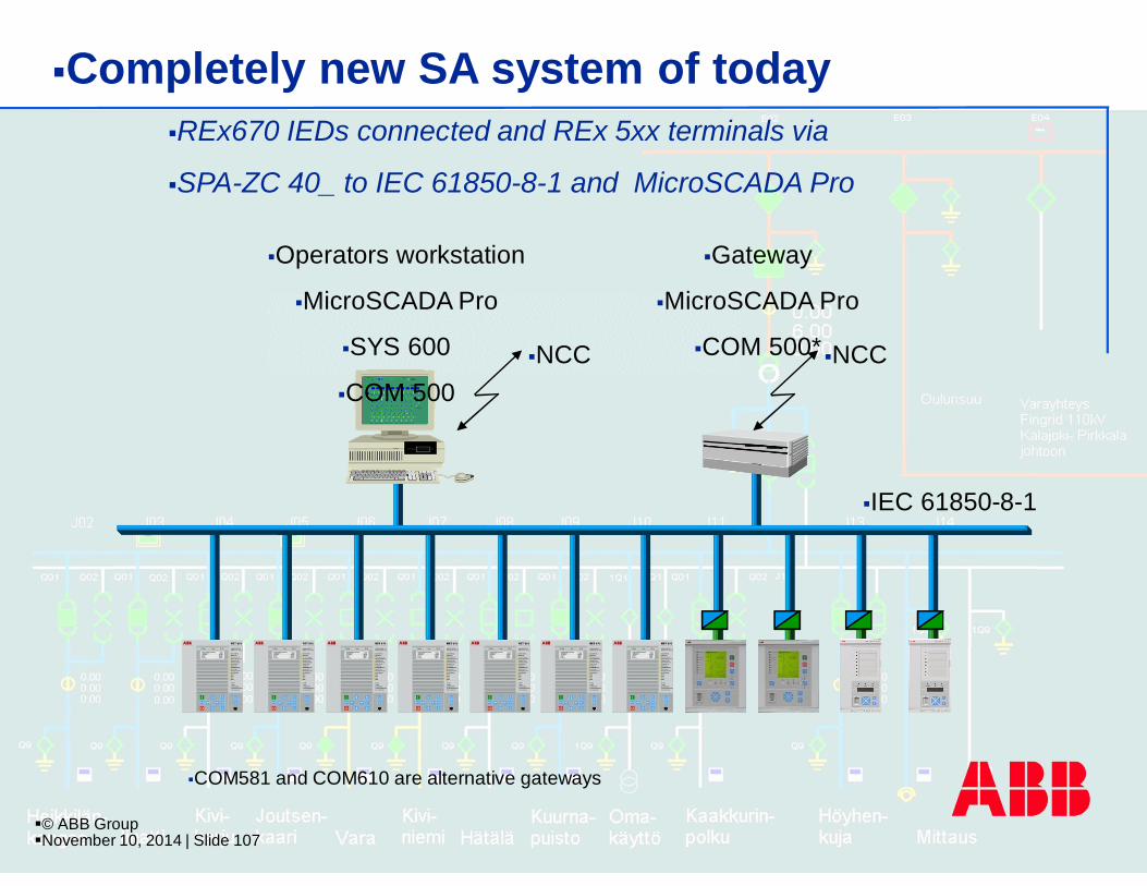
§REx670 IEDs connected and REx 5xx terminals via
§SPA-ZC 40_ to IEC 61850-8-1 and MicroSCADA Pro
§Completely new SA system of today
§Operators workstation
§MicroSCADA Pro
§SYS 600
§COM 500§NCC
§COM581 and COM610 are alternative gateways
§© ABB Group§November 10, 2014 | Slide 107

§NCC
§Gateway
§MicroSCADA Pro
§COM 500
§IEC 61850-8-1
§TCP/IP
§REx670 IEDs connected to IEC 61850-8-1 and MicroSCADA Pro
§Completely new SCS/SA system of today
§Operators workstation
§MicroSCADA Pro
§SYS 600
§Remote SMS workplace
§with PCM600
§© ABB Group§November 10, 2014 | Slide 108

§NCC
§Third party Gateway
§IEC 61850-8-1
§TCP/IP
§REx670 IEDs connected to IEC 61850-8-1 and MicroSCADA Pro
§Completely new SCS/SA system of today
§Third party HSI§Remote SMS workplace
§with PCM600
§© ABB Group§November 10, 2014 | Slide 109

Open to integration
§Capacitor
§Bank
§ Meas.
§Cubicle
§Q§0
§Q§1
§I§,§Q
§Q§1
§Q§9
§I§,§P§Q
§Q§0
§Q§1
§I§,§P§Q
§Q§0
§Q§1
§S§T§r
§I§,§P§,§Q
§Q§0
§Q§1 §Q§1
§I
§Q§0
§Q§1
§I§,§P§,§Q
§Q§0
§Q§1
§M
§Q§0
§Q§1
§Q§1§1
§Q§1§2
§I§,§P§,§Q
§I§,§P§,§Q§,§E§Q§9
§Q§9§I§,§P§,§Q
§Q§0
§Q§1
§Q§1§1
§Q§1§2
§I§,§P§,§Q
§I§,§P§,§Q§,§E§Q§9
§Q§3
§Q§9
§Q§4
§Q§0
§I§,§P§,§Q§,§E
§Q§a §Q§b
§Q§0
§I
§Q§5§Q§5§9
§Q§3
§Q§9
§Q§4
§Q§0
§I§,§P§,§Q§,§E
§Q§6 §Q§6§9
§I§,§P§,§Q
§Q§0
§Q§1
§Q§0
§Q§1
§Q§1
§Q§0
§Q§1
§I§,§Q
§110 kVBus Bar
§6 kVBus Bar
§Cable
§Feeder
§Overhead line
§Feeder
§S / Aux.
§Tr.
§Section
§CB
§Motor
§Feeder
§Overhead line
§Feeder
§Cable
§Feeder
§ Meas.
§Cubicle
§Capacitor
§Bank
§110kV
§Incoming Line
§110kV
§Incoming Line
§Tr. 1. Incoming
§Feeder
§Tr. 2. Incoming
§Feeder
§Section
§CB
§MicroSCADA Pro§Process Automation
§OPC
§Information Integration§Superior information handling
§One environment
§ … an integration solution
§© ABB Group§November 10, 2014 | Slide 110

Related Documents