© 2014 BAKER HUGHES INCORPORATED. ALL RIGHTS RESERVED. TERMS AND CONDITIONS OF USE: BY ACCEPTING THIS DOCUMENT, THE RECIPIENT AGREES THAT THE DOCUMENT TOGETHER WITH ALL INFORMATION INCLUDED THEREIN IS THE CONFIDENTIAL AND PROPRIETARY PROPERTY OF BAKER HUGHES INCORPORATED AND INCLUDES VALUABLE TRADE SECRETS AND/OR PROPRIETARY INFORMATION OF BAKER HUGHES (COLLECTIVELY "INFORMATION"). BAKER HUGHES RETAINS ALL RIGHTS UNDER COPYRIGHT LAWS AND TRADE SECRET LAWS OF THE UNITED STATES OF AMERICA AND OTHER COUNTRIES. THE RECIPIENT FURTHER AGREES THAT THE DOCUMENT MAY NOT BE DISTRIBUTED, TRANSMITTED, COPIED OR REPRODUCED IN WHOLE OR IN PART BY ANY MEANS, ELECTRONIC, MECHANICAL, OR OTHERWISE, WITHOUT THE EXPRESS PRIOR WRITTEN CONSENT OF BAKER HUGHES, AND MA Y NOT BE USED DIRECTLY OR INDIRECTLY IN ANY WAY DETRIMENTAL TO BAKER HUGHES’ INTEREST. Downhole Oil & Water Separation A New Start Presenter: Ed Sheridan Baker Hughes

Welcome message from author
This document is posted to help you gain knowledge. Please leave a comment to let me know what you think about it! Share it to your friends and learn new things together.
Transcript
© 2014 BAKER HUGHES INCORPORATED. ALL RIGHTS RESERVED. TERMS AND CONDITIONS OF USE: BY ACCEPTING THIS DOCUMENT, THE RECIPIENT AGREES THAT THE DOCUMENT TOGETHER WITH ALL INFORMATION INCLUDED THEREIN IS THE
CONFIDENTIAL AND PROPRIETARY PROPERTY OF BAKER HUGHES INCORPORATED AND INCLUDES VALUABLE TRADE SECRETS AND/OR PROPRIETARY INF ORMATION OF BAKER HUGHES (COLLECTIVELY " INFORMATION"). BAKER HUGHES RETAINS ALL RIGHTS
UNDER COPYRIGHT LAWS AND TRADE SECRET LAWS OF THE UNITED STATES OF AMERICA AND OTHER COUNTRIES. THE RECIPIENT FURTHER AGREES TH AT THE DOCUMENT MAY NOT BE DISTRIBUTED, TRANSMITTED, COPIED OR REPRODUCED IN WHOLE OR
IN PART BY ANY MEANS, ELECTRONIC, MECHANICAL, OR OTHERWISE, WITHOUT THE EXPRESS PRIOR WRITTEN CONSENT OF BAKER HUGHES, AND MA Y NOT BE USED DIRECTLY OR INDIRECTLY IN ANY WAY DETRIMENTAL TO BAKER HUGHES’ INTEREST.
Downhole Oil & Water Separation A New Start
Presenter: Ed Sheridan
Baker Hughes
SubSep - Downhole Oil & Water Separation
• Summary of Previous Experience
• What has changed?
• New Design
• China Application
• China Design
• China Performance
• System operation
• Technical Requirements
• Keys to Success
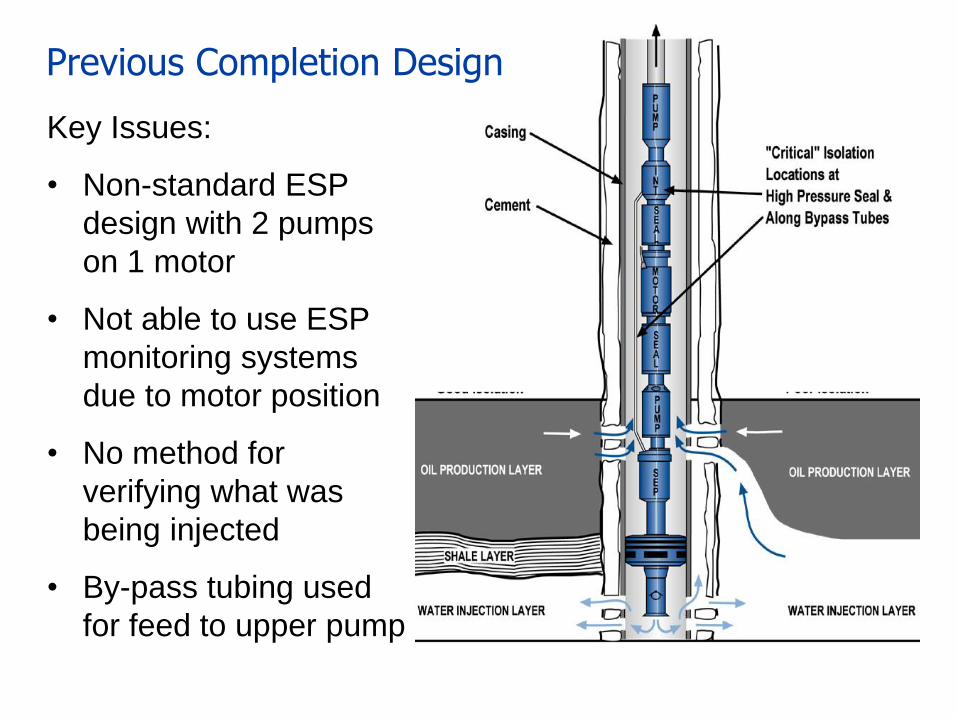
Key Issues:
• Non-standard ESP
design with 2 pumps
on 1 motor
• Not able to use ESP
monitoring systems
due to motor position
• No method for
verifying what was
being injected
• By-pass tubing used
for feed to upper pump
Previous Completion Design
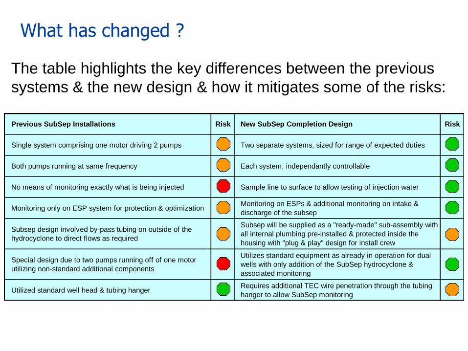
The table highlights the key differences between the previous
systems & the new design & how it mitigates some of the risks:
What has changed ?
Previous SubSep Installations Risk New SubSep Completion Design Risk
Single system comprising one motor driving 2 pumps Two separate systems, sized for range of expected duties
Both pumps running at same frequency Each system, independantly controllable
No means of monitoring exactly what is being injected Sample line to surface to allow testing of injection water
Monitoring only on ESP system for protection & optimizationMonitoring on ESPs & additional monitoring on intake &
discharge of the subsep
Subsep design involved by-pass tubing on outside of the
hydrocyclone to direct flows as required
Subsep will be supplied as a "ready-made" sub-assembly with
all internal plumbing pre-installed & protected inside the
housing with "plug & play" design for install crew
Special design due to two pumps running off of one motor
utilizing non-standard additional components
Utilizes standard equipment as already in operation for dual
wells with only addition of the SubSep hydrocyclone &
associated monitoring
Utilized standard well head & tubing hangerRequires additional TEC wire penetration through the tubing
hanger to allow SubSep monitoring
New Design - Philosophy
• To address the concerns raised & lessons learned from
previous installations
• To simplify the SubSep system & completion design
• To keep the ESP part of the completion the same whether
the Injection Zone is above or below the Production Zone
• Keeping ESP section the same would allow a standardized
control & operation methodology to be developed.
• Wherever possible, use only standard equipment already
commonly in use for ESP completions
• Update the SubSep hydrocyclone to a “plug & play” design
• Use a Sample Line to verify separation efficiency
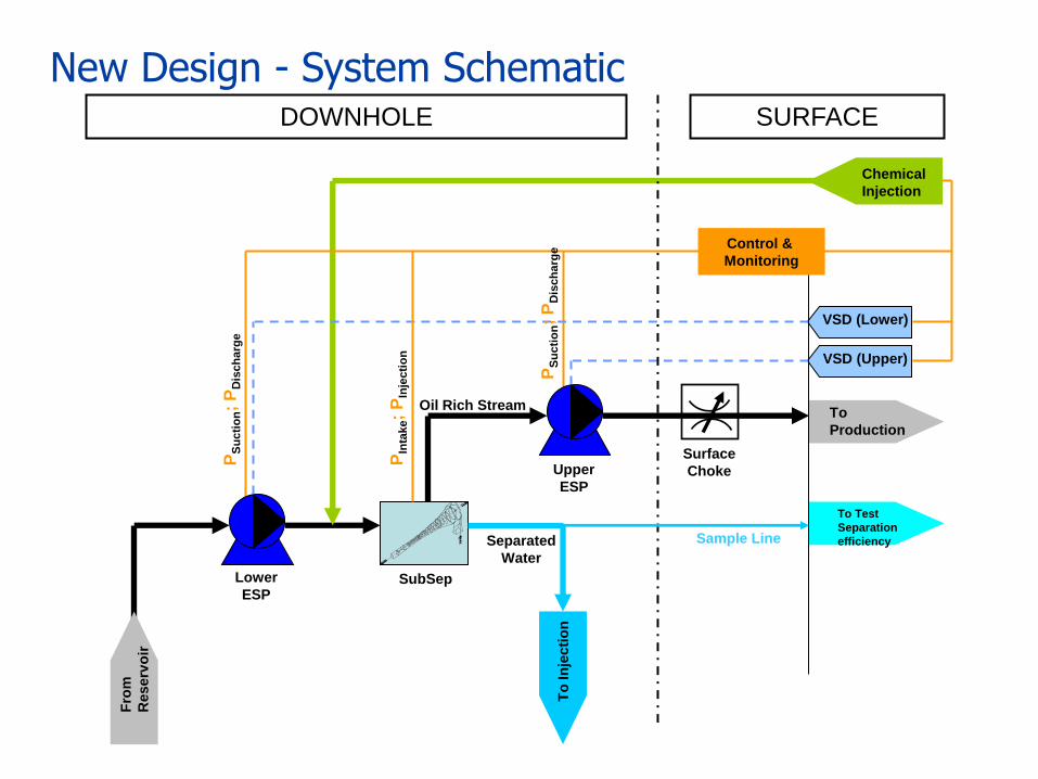
New Design - System Schematic DOWNHOLE SURFACE
Fro
m
Reserv
oir
To
In
jecti
on
To
Production
Chemical
Injection
Control &
Monitoring
VSD (Lower)
VSD (Upper)
Lower
ESP SubSep
Upper
ESP
Surface
Choke
Oil Rich Stream
Separated
Water
PIn
take;
PIn
jecti
on
PS
uc
tio
n;
PD
isch
arg
e
PS
uc
tio
n;
PD
isch
arg
e
To Test
Separation
efficiency Sample Line
System Operation
• Fluid from Production Zone flows
into the lower ESP and then on to
the SubSep at required pressure
• Separated Water stream directed
to the injection zone above the
Production Zone
• Separated oil rich fluid is forced to
the Upper ESP which is used to
produce to the surface
Production Zone
Injection Zone
Lower ESP
SubSep
Upper ESP
Inj. Zone Gauge
Sample Line
Production Zone
Injection Zone
Lower ESP
SubSep
Upper ESP
Inj. Zone Gauge
Sample Line
Production Zone
Injection Zone
Lower ESP
SubSep
Upper ESP
Inj. Zone Gauge
Sample Line
• Injection stream water can be
sampled at surface or flow
direction can be reversed for
chemical injection
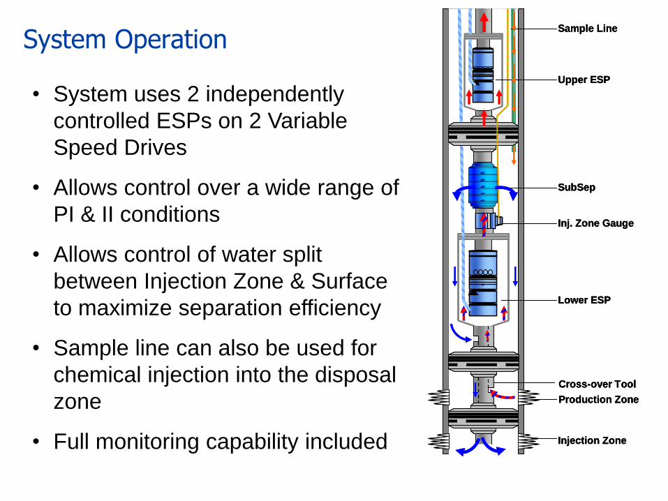
System Operation
• System uses 2 independently
controlled ESPs on 2 Variable
Speed Drives
• Allows control over a wide range of
PI & II conditions
• Allows control of water split
between Injection Zone & Surface
to maximize separation efficiency
• Sample line can also be used for
chemical injection into the disposal
zone
• Full monitoring capability included
Production Zone
Injection Zone
Lower ESP
SubSep
Upper ESP
Inj. Zone Gauge
Sample Line
Cross-over Tool
Production Zone
Injection Zone
Lower ESP
SubSep
Upper ESP
Inj. Zone Gauge
Sample Line
Cross-over Tool
Production Zone
Injection Zone
Lower ESP
SubSep
Upper ESP
Inj. Zone Gauge
Sample Line
Cross-over Tool
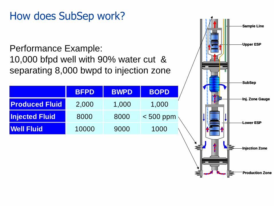
BFPD BWPD BOPD
Produced Fluid 2,000 1,000 1,000
Injected Fluid 8000 8000 < 500 ppm
Well Fluid 10000 9000 1000
How does SubSep work?
Performance Example:
10,000 bfpd well with 90% water cut &
separating 8,000 bwpd to injection zone
Production Zone
Injection Zone
Lower ESP
SubSep
Upper ESP
Inj. Zone Gauge
Sample Line
Production Zone
Injection Zone
Lower ESP
SubSep
Upper ESP
Inj. Zone Gauge
Sample Line
Production Zone
Injection Zone
Lower ESP
SubSep
Upper ESP
Inj. Zone Gauge
Sample Line
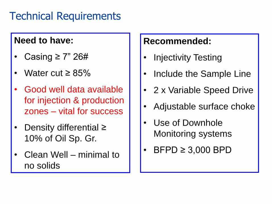
Technical Requirements
Need to have:
• Casing ≥ 7” 26#
• Water cut ≥ 85%
• Good well data available
for injection & production
zones – vital for success
• Density differential ≥
10% of Oil Sp. Gr.
• Clean Well – minimal to
no solids
Recommended:
• Injectivity Testing
• Include the Sample Line
• 2 x Variable Speed Drive
• Adjustable surface choke
• Use of Downhole
Monitoring systems
• BFPD ≥ 3,000 BPD
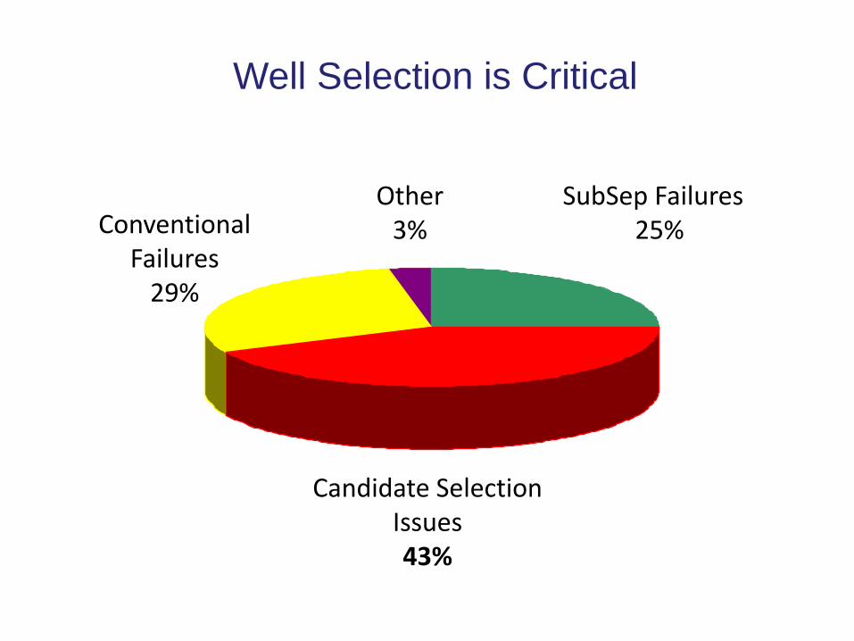
Well Selection is Critical Well Selection is Critical
SubSep Failures 25%
Candidate Selection Issues 43%
Conventional Failures
29%
Other 3%
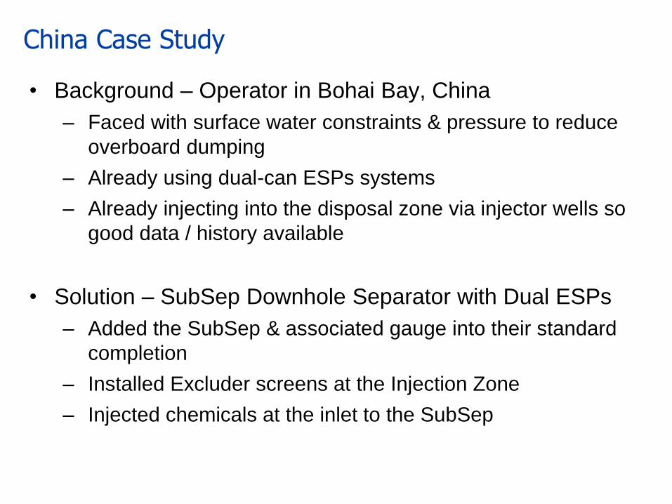
China Case Study
• Background – Operator in Bohai Bay, China
– Faced with surface water constraints & pressure to reduce
overboard dumping
– Already using dual-can ESPs systems
– Already injecting into the disposal zone via injector wells so
good data / history available
• Solution – SubSep Downhole Separator with Dual ESPs
– Added the SubSep & associated gauge into their standard
completion
– Installed Excluder screens at the Injection Zone
– Injected chemicals at the inlet to the SubSep
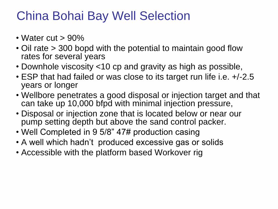
China Bohai Bay Well Selection
• Water cut > 90%
• Oil rate > 300 bopd with the potential to maintain good flow rates for several years
• Downhole viscosity <10 cp and gravity as high as possible,
• ESP that had failed or was close to its target run life i.e. +/-2.5 years or longer
• Wellbore penetrates a good disposal or injection target and that can take up 10,000 bfpd with minimal injection pressure,
• Disposal or injection zone that is located below or near our pump setting depth but above the sand control packer.
• Well Completed in 9 5/8” 47# production casing
• A well which hadn’t produced excessive gas or solids
• Accessible with the platform based Workover rig
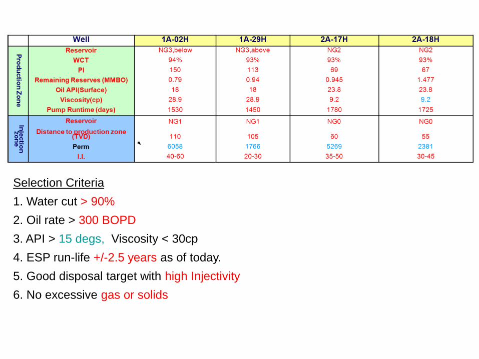
Selection Criteria
1. Water cut > 90%
2. Oil rate > 300 BOPD
3. API > 15 degs, Viscosity < 30cp
4. ESP run-life +/-2.5 years as of today.
5. Good disposal target with high Injectivity
6. No excessive gas or solids
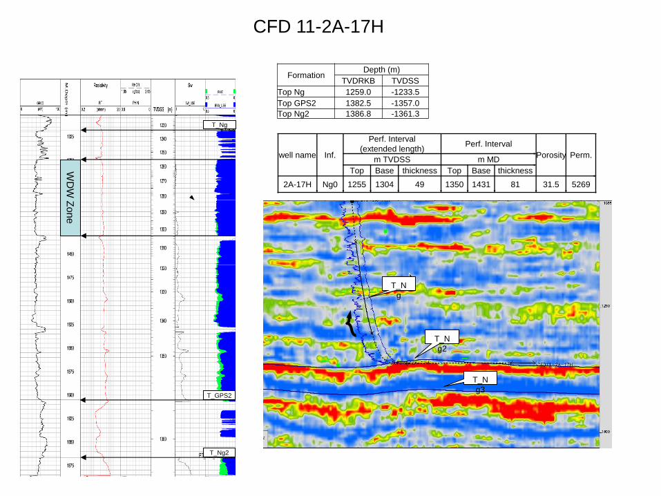
Formation Depth (m)
TVDRKB TVDSS
Top Ng 1259.0 -1233.5
Top GPS2 1382.5 -1357.0
Top Ng2 1386.8 -1361.3
well name Inf.
Perf. Interval
(extended length) Perf. Interval
Porosity Perm. m TVDSS m MD
Top Base thickness Top Base thickness
2A-17H Ng0 1255 1304 49 1350 1431 81 31.5 5269
CFD 11-2A-17H
T_N
g
T_N
g3
T_N
g2
T_Ng
T_GPS2
T_Ng2
WD
W Z
on
e
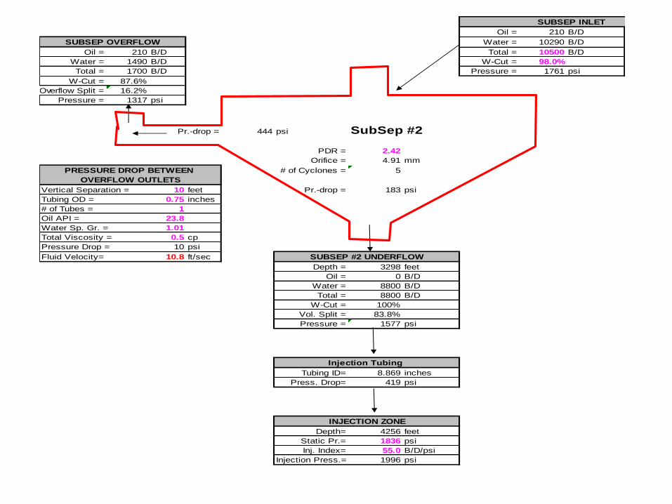
SUBSEP INLET
Oil = 210 B/D
SUBSEP OVERFLOW Water = 10290 B/D
Oil = 210 B/D Total = 10500 B/D
Water = 1490 B/D W-Cut = 98.0%
Total = 1700 B/D Pressure = 1761 psi
W-Cut = 87.6%
Overflow Split = 16.2%
Pressure = 1317 psi
Pr.-drop = 444 psi SubSep #2
PDR = 2.42
Orifice = 4.91 mm
PRESSURE DROP BETWEEN # of Cyclones = 5
OVERFLOW OUTLETS
Vertical Separation = 10 feet Pr.-drop = 183 psi
Tubing OD = 0.75 inches
# of Tubes = 1
Oil API = 23.8
Water Sp. Gr. = 1.01
Total Viscosity = 0.5 cp
Pressure Drop = 10 psi
Fluid Velocity= 10.8 ft/sec SUBSEP #2 UNDERFLOW
Depth = 3298 feet
Oil = 0 B/D
Water = 8800 B/D
Total = 8800 B/D
W-Cut = 100%
Vol. Split = 83.8%
Pressure = 1577 psi
Tubing ID= 8.869 inches
Press. Drop= 419 psi
Depth= 4256 feet
Static Pr.= 1836 psi
Inj. Index= 55.0 B/D/psi
Injection Press.= 1996 psi
Injection Tubing
INJECTION ZONE
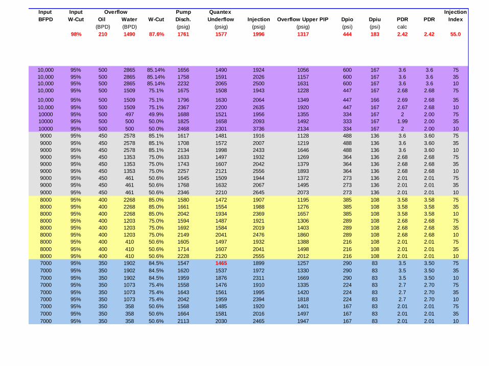
Input Input Overflow Pump Quantex Injection
BFPD W-Cut Oil Water W-Cut Disch. Underflow Injection Overflow Upper PIP Dpio Dpiu PDR PDR Index
(BPD) (BPD) (psig) (psig) (psig) (psig) (psi) (psi) calc
98% 210 1490 87.6% 1761 1577 1996 1317 444 183 2.42 2.42 55.0
10,000 95% 500 2865 85.14% 1656 1490 1924 1056 600 167 3.6 3.6 75
10,000 95% 500 2865 85.14% 1758 1591 2026 1157 600 167 3.6 3.6 35
10,000 95% 500 2865 85.14% 2232 2065 2500 1631 600 167 3.6 3.6 10
10,000 95% 500 1509 75.1% 1675 1508 1943 1228 447 167 2.68 2.68 75
10,000 95% 500 1509 75.1% 1796 1630 2064 1349 447 166 2.69 2.68 35
10,000 95% 500 1509 75.1% 2367 2200 2635 1920 447 167 2.67 2.68 10
10000 95% 500 497 49.9% 1688 1521 1956 1355 334 167 2 2.00 75
10000 95% 500 500 50.0% 1825 1658 2093 1492 333 167 1.99 2.00 35
10000 95% 500 500 50.0% 2468 2301 3736 2134 334 167 2 2.00 10
9000 95% 450 2578 85.1% 1617 1481 1916 1128 488 136 3.6 3.60 75
9000 95% 450 2578 85.1% 1708 1572 2007 1219 488 136 3.6 3.60 35
9000 95% 450 2578 85.1% 2134 1998 2433 1646 488 136 3.6 3.60 10
9000 95% 450 1353 75.0% 1633 1497 1932 1269 364 136 2.68 2.68 75
9000 95% 450 1353 75.0% 1743 1607 2042 1379 364 136 2.68 2.68 35
9000 95% 450 1353 75.0% 2257 2121 2556 1893 364 136 2.68 2.68 10
9000 95% 450 461 50.6% 1645 1509 1944 1372 273 136 2.01 2.01 75
9000 95% 450 461 50.6% 1768 1632 2067 1495 273 136 2.01 2.01 35
9000 95% 450 461 50.6% 2346 2210 2645 2073 273 136 2.01 2.01 10
8000 95% 400 2268 85.0% 1580 1472 1907 1195 385 108 3.58 3.58 75
8000 95% 400 2268 85.0% 1661 1554 1988 1276 385 108 3.58 3.58 35
8000 95% 400 2268 85.0% 2042 1934 2369 1657 385 108 3.58 3.58 10
8000 95% 400 1203 75.0% 1594 1487 1921 1306 289 108 2.68 2.68 75
8000 95% 400 1203 75.0% 1692 1584 2019 1403 289 108 2.68 2.68 35
8000 95% 400 1203 75.0% 2149 2041 2476 1860 289 108 2.68 2.68 10
8000 95% 400 410 50.6% 1605 1497 1932 1388 216 108 2.01 2.01 75
8000 95% 400 410 50.6% 1714 1607 2041 1498 216 108 2.01 2.01 35
8000 95% 400 410 50.6% 2228 2120 2555 2012 216 108 2.01 2.01 10
7000 95% 350 1902 84.5% 1547 1465 1899 1257 290 83 3.5 3.50 75
7000 95% 350 1902 84.5% 1620 1537 1972 1330 290 83 3.5 3.50 35
7000 95% 350 1902 84.5% 1959 1876 2311 1669 290 83 3.5 3.50 10
7000 95% 350 1073 75.4% 1558 1476 1910 1335 224 83 2.7 2.70 75
7000 95% 350 1073 75.4% 1643 1561 1995 1420 224 83 2.7 2.70 35
7000 95% 350 1073 75.4% 2042 1959 2394 1818 224 83 2.7 2.70 10
7000 95% 350 358 50.6% 1568 1485 1920 1401 167 83 2.01 2.01 75
7000 95% 350 358 50.6% 1664 1581 2016 1497 167 83 2.01 2.01 35
7000 95% 350 358 50.6% 2113 2030 2465 1947 167 83 2.01 2.01 10
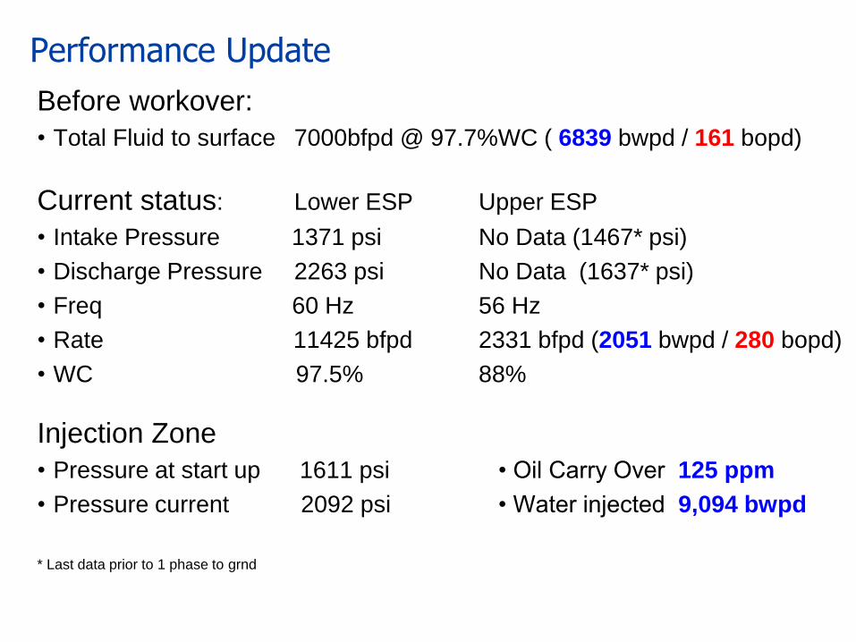
Performance Update
Before workover:
• Total Fluid to surface 7000bfpd @ 97.7%WC ( 6839 bwpd / 161 bopd)
Current status: Lower ESP Upper ESP
• Intake Pressure 1371 psi No Data (1467* psi)
• Discharge Pressure 2263 psi No Data (1637* psi)
• Freq 60 Hz 56 Hz
• Rate 11425 bfpd 2331 bfpd (2051 bwpd / 280 bopd)
• WC 97.5% 88%
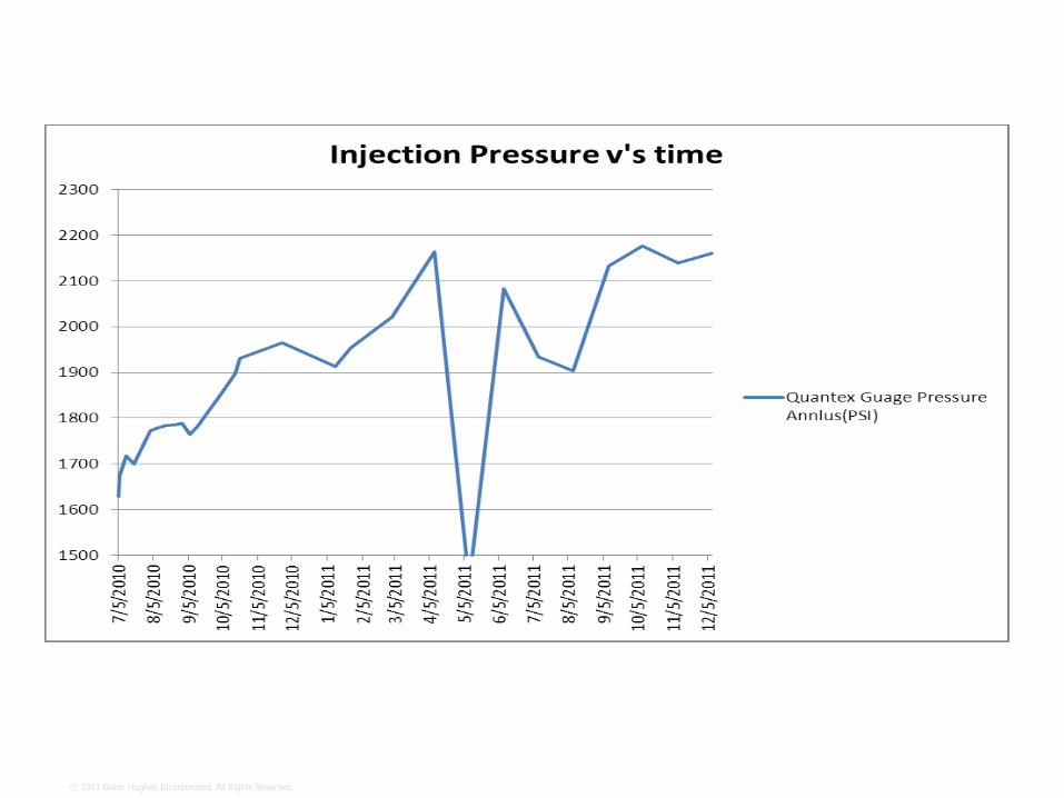
Injection Zone
• Pressure at start up 1611 psi • Oil Carry Over 125 ppm
• Pressure current 2092 psi • Water injected 9,094 bwpd
* Last data prior to 1 phase to grnd
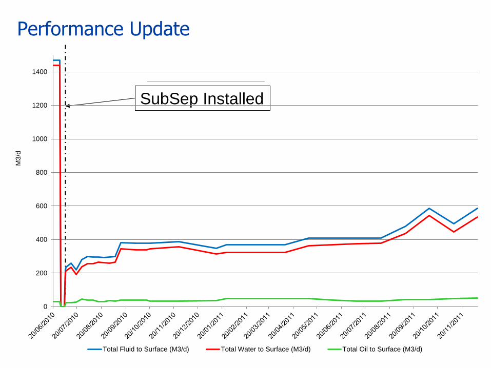
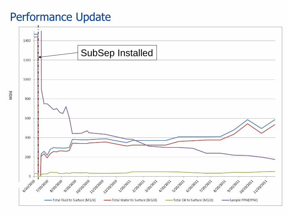
Performance Update
SubSep Installed SubSep Installed
M3/d
0
200
400
600
800
1000
1200
1400
Total Fluid to Surface (M3/d) Total Water to Surface (M3/d) Total Oil to Surface (M3/d)
Performance Update M
3/d
SubSep Installed
Update on the Bohai Bay application
© 2011 Baker Hughes Incorporated. All Rights Reserved. 24
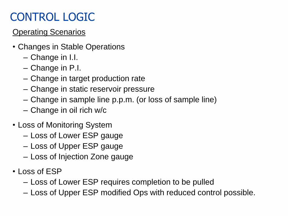
CONTROL LOGIC
Operating Scenarios
• Changes in Stable Operations
– Change in I.I.
– Change in P.I.
– Change in target production rate
– Change in static reservoir pressure
– Change in sample line p.p.m. (or loss of sample line)
– Change in oil rich w/c
• Loss of Monitoring System
– Loss of Lower ESP gauge
– Loss of Upper ESP gauge
– Loss of Injection Zone gauge
• Loss of ESP
– Loss of Lower ESP requires completion to be pulled
– Loss of Upper ESP modified Ops with reduced control possible.
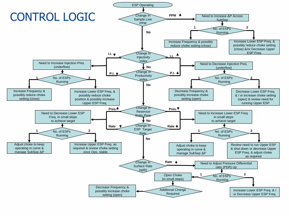
ESP Operating
2
No
Need to Increase ΔP Across
SubSep
No. of ESPs
Running
Increase Frequency & possibly
reduce choke setting (close)
Increase Lower ESP Freq. &
possibly reduce choke setting
(close) &/or Decrease Upper
ESP Freq.
1
Change in
Injectivity
Index Need to Decrease Injection Pres.
(underflow)
Change in
Productivity
Index 2
Need to Increase Injection Pres.
(underflow)
No. of ESPs
Running
Increase Frequency &
possibly reduce choke
setting (close)
1
I.I. I.I.
P.I. P.I.
No
PPM
2 No. of ESPs
Running
1
Increase Lower ESP Freq. &
possibly reduce choke
position & possibly increase
Upper ESP Freq.
Decrease Lower ESP Freq.
& / or increase choke setting
(open) & review need for
running Upper ESP
Decrease Frequency &
possibly increase choke
setting (open)
Change in
Reservoir
Static Pres. Need to Increase Lower ESP Freq.
in small steps
to achieve target
Change in
ESP Target
Rate 2
Need to Decrease Lower ESP
Freq. in small steps
to achieve target
No. of ESPs
Running
1
Pres. Pres.
No
2 No. of ESPs
Running
1
Review need to run Upper ESP
& shut down or decrease Upper
ESP Freq. & adjust choke
as required
Increase Upper ESP Freq. as
required & review choke setting
once Ops. stable
Adjust choke to keep
operating in curve &
manage SubSep ΔP
No
Rate Rate
Adjust choke to keep
operating in curve &
manage SubSep ΔP
2
Change in
Surface Rate
(split)
No
No. of ESPs
Running
Increase Lower ESP Freq. & /
or Decrease Upper ESP Freq.
1
Rate Need to Adjust Pressure Differential
ratio (PDR) Up
Additional Change
Required
Open Choke
(in small steps)
Decrease Frequency &
possibly increase choke
setting (open)
CONTROL LOGIC Change in
Sample Line
PPM
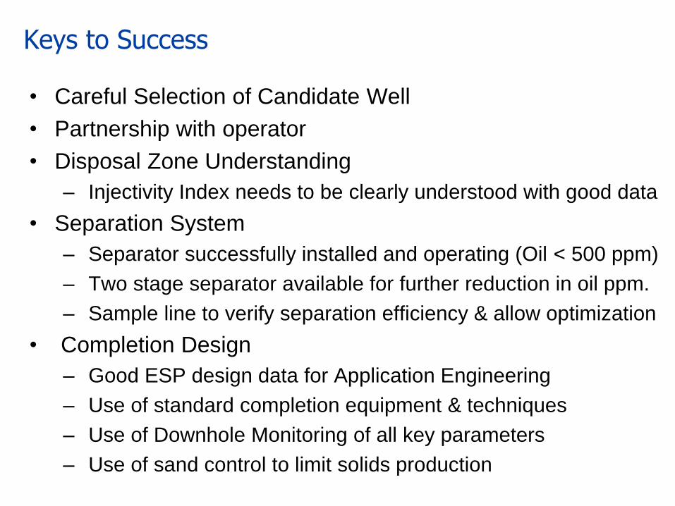
Keys to Success
• Careful Selection of Candidate Well
• Partnership with operator
• Disposal Zone Understanding
– Injectivity Index needs to be clearly understood with good data
• Separation System
– Separator successfully installed and operating (Oil < 500 ppm)
– Two stage separator available for further reduction in oil ppm.
– Sample line to verify separation efficiency & allow optimization
• Completion Design
– Good ESP design data for Application Engineering
– Use of standard completion equipment & techniques
– Use of Downhole Monitoring of all key parameters
– Use of sand control to limit solids production
Don’t Just Count What is Produced: Produce What Counts !
Related Documents


![Gypsum in C&D aggregates – Origin, Effects, [Separation] and Utilization](https://static.cupdf.com/doc/110x72/64481f5b84b8c36d300b95ff/gypsum-in-cd-aggregates-a-origin-effects-separation-and-utilization.jpg)