Prepared for: Submittal for Approval Negotiation Number Volume 1 of 1 Equipment: Automatic Transfer Switch Date: 3/29/2021 ©2021 Eaton Corporation, All Rights Reserved

Welcome message from author
This document is posted to help you gain knowledge. Please leave a comment to let me know what you think about it! Share it to your friends and learn new things together.
Transcript

Prepared for:
Submittal for Approval
Negotiation Number
Volume 1 of 1
Equipment:
Automatic Transfer Switch
Date: 3/29/2021 ©2021 Eaton Corporation, All Rights Reserved
Detail Bill of Material Page 1 of 4Project Name: Negotiation No: General Order No: Alternate No: 0000
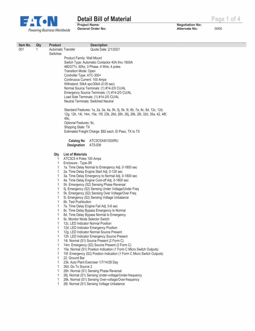
Item No. Qty Product Description 001 1 Automatic Transfer
Switches Quote Date: 2/1/2021
Product Family: Wall Mount Switch Type: Automatic Contactor 40A thru 1600A 480/277v, 60hz, 3 Phase, 4 Wire, 4 poles Transition Mode: Open Controller Type: ATC-300+ Continuous Current: 100 Amps Withstand: 50kA spc/30kA (0.05 sec) Normal Source Terminals: (1) #14-2/0 CU/AL Emergency Source Terminals: (1) #14-2/0 CU/AL Load Side Terminals: (1) #14-2/0 CU/AL Neutral Terminals: Switched Neutral
Standard Features: 1a, 2a, 3a, 4a, 5h, 5j, 5k, 5l, 6b, 7a, 8c, 8d, 12c, 12d, 12g, 12h, 14l, 14m, 15e, 15f, 23k, 26d, 26h, 26j, 26k, 26l, 32d, 35a, 42, 48f, 49c, Optional Features: 9c, Shipping State: TX Estimated Freight Charge: $92 each, El Paso, TX to TX
Catalog No ATC3C5X40100XRU Designation ATS-EM
Qty List of Materials 1 ATC3C5 4 Poles 100 Amps 1 Enclosure - Type-3R 1 1a. Time Delay Normal to Emergency Adj. 0-1800 sec 1 2a. Time Delay Engine Start Adj. 0-120 sec 1 3a. Time Delay Emergency to Normal Adj. 0-1800 sec 1 4a. Time Delay Engine Cool-off Adj. 0-1800 sec 1 5h. Emergency (S2) Sensing Phase Reversal 1 5j. Emergency (S2) Sensing Under Voltage/Under Freq 1 5k. Emergency (S2) Sensing Over Voltage/Over Freq 1 5l. Emergency (S2) Sensing Voltage Unbalance 1 6b. Test Pushbutton 1 7a. Time Delay Engine Fail Adj. 0-6 sec 1 8c. Time Delay Bypass Emergency to Normal 1 8d. Time Delay Bypass Normal to Emergency 1 9c. Monitor Mode Selector Switch 1 12c. LED Indicator Normal Position 1 12d. LED Indicator Emergency Position 1 12g. LED Indicator Normal Source Present 1 12h. LED Indicator Emergency Source Present 1 14l. Normal (S1) Source Present (2 Form C) 1 14m. Emergency (S2) Source Present (2 Form C) 1 15e. Normal (S1) Position Indication (1 Form C Micro Switch Outputs) 1 15f. Emergency (S2) Position Indication (1 Form C Micro Switch Outputs) 1 22. Ground Bar 1 23k. Auto Plant Exerciser 1/7/14/28 Day 1 26d. Go To Source 2 1 26h. Normal (S1) Sensing Phase Reversal 1 26j. Normal (S1) Sensing Under-voltage/Under-frequency 1 26k. Normal (S1) Sensing Over-voltage/Over-frequency 1 26l. Normal (S1) Sensing Voltage Unbalance
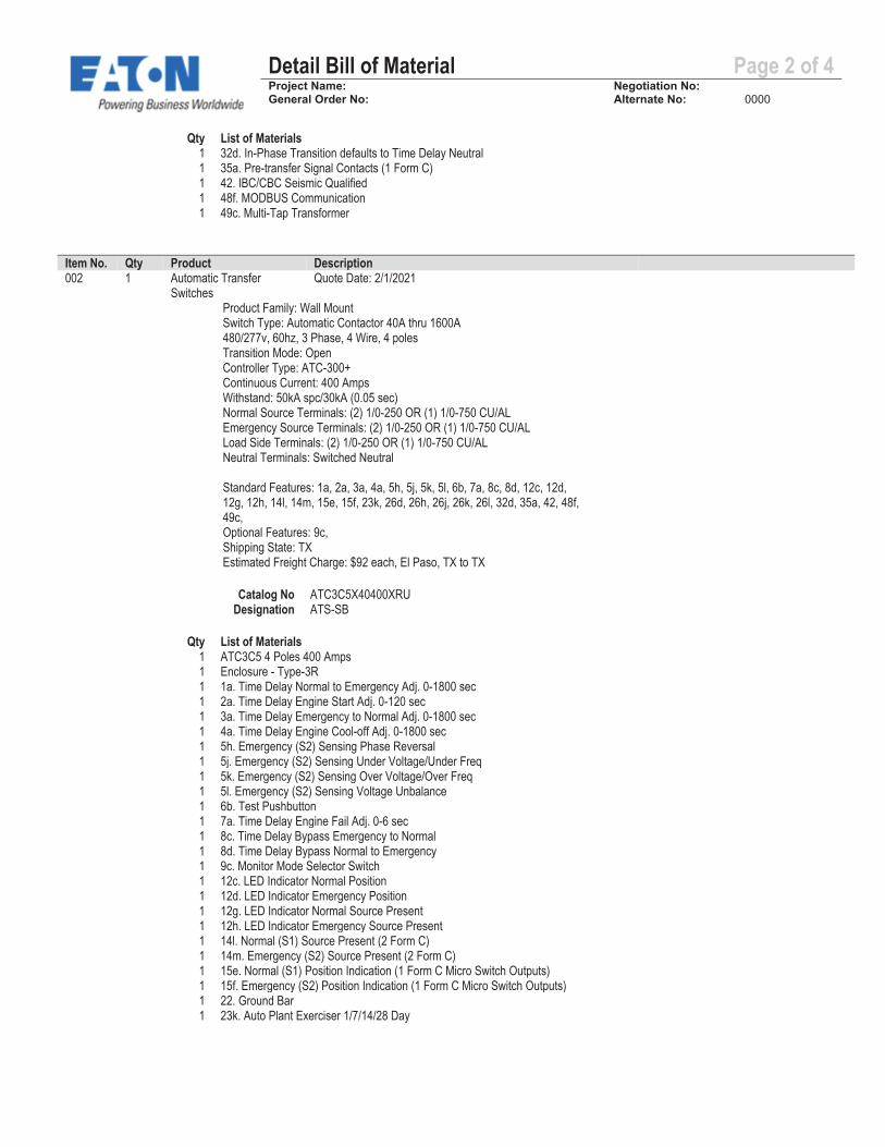
Detail Bill of Material Page 2 of 4Project Name: Negotiation No: General Order No: Alternate No: 0000
Qty List of Materials 1 32d. In-Phase Transition defaults to Time Delay Neutral 1 35a. Pre-transfer Signal Contacts (1 Form C) 1 42. IBC/CBC Seismic Qualified 1 48f. MODBUS Communication 1 49c. Multi-Tap Transformer
Item No. Qty Product Description 002 1 Automatic Transfer
Switches Quote Date: 2/1/2021
Product Family: Wall Mount Switch Type: Automatic Contactor 40A thru 1600A 480/277v, 60hz, 3 Phase, 4 Wire, 4 poles Transition Mode: Open Controller Type: ATC-300+ Continuous Current: 400 Amps Withstand: 50kA spc/30kA (0.05 sec) Normal Source Terminals: (2) 1/0-250 OR (1) 1/0-750 CU/AL Emergency Source Terminals: (2) 1/0-250 OR (1) 1/0-750 CU/AL Load Side Terminals: (2) 1/0-250 OR (1) 1/0-750 CU/AL Neutral Terminals: Switched Neutral
Standard Features: 1a, 2a, 3a, 4a, 5h, 5j, 5k, 5l, 6b, 7a, 8c, 8d, 12c, 12d, 12g, 12h, 14l, 14m, 15e, 15f, 23k, 26d, 26h, 26j, 26k, 26l, 32d, 35a, 42, 48f, 49c, Optional Features: 9c, Shipping State: TX Estimated Freight Charge: $92 each, El Paso, TX to TX
Catalog No ATC3C5X40400XRU Designation ATS-SB
Qty List of Materials 1 ATC3C5 4 Poles 400 Amps 1 Enclosure - Type-3R 1 1a. Time Delay Normal to Emergency Adj. 0-1800 sec 1 2a. Time Delay Engine Start Adj. 0-120 sec 1 3a. Time Delay Emergency to Normal Adj. 0-1800 sec 1 4a. Time Delay Engine Cool-off Adj. 0-1800 sec 1 5h. Emergency (S2) Sensing Phase Reversal 1 5j. Emergency (S2) Sensing Under Voltage/Under Freq 1 5k. Emergency (S2) Sensing Over Voltage/Over Freq 1 5l. Emergency (S2) Sensing Voltage Unbalance 1 6b. Test Pushbutton 1 7a. Time Delay Engine Fail Adj. 0-6 sec 1 8c. Time Delay Bypass Emergency to Normal 1 8d. Time Delay Bypass Normal to Emergency 1 9c. Monitor Mode Selector Switch 1 12c. LED Indicator Normal Position 1 12d. LED Indicator Emergency Position 1 12g. LED Indicator Normal Source Present 1 12h. LED Indicator Emergency Source Present 1 14l. Normal (S1) Source Present (2 Form C) 1 14m. Emergency (S2) Source Present (2 Form C) 1 15e. Normal (S1) Position Indication (1 Form C Micro Switch Outputs) 1 15f. Emergency (S2) Position Indication (1 Form C Micro Switch Outputs) 1 22. Ground Bar 1 23k. Auto Plant Exerciser 1/7/14/28 Day
Detail Bill of Material Page 3 of 4Project Name: Negotiation No: General Order No: Alternate No: 0000
Qty List of Materials 1 26d. Go To Source 2 1 26h. Normal (S1) Sensing Phase Reversal 1 26j. Normal (S1) Sensing Under-voltage/Under-frequency 1 26k. Normal (S1) Sensing Over-voltage/Over-frequency 1 26l. Normal (S1) Sensing Voltage Unbalance 1 32d. In-Phase Transition defaults to Time Delay Neutral 1 35a. Pre-transfer Signal Contacts (1 Form C) 1 42. IBC/CBC Seismic Qualified 1 48f. MODBUS Communication 1 49c. Multi-Tap Transformer
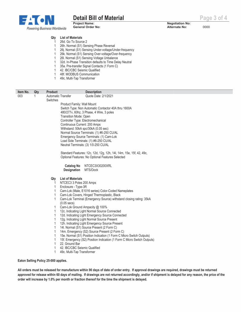
Item No. Qty Product Description 003 1 Automatic Transfer
Switches Quote Date: 2/1/2021
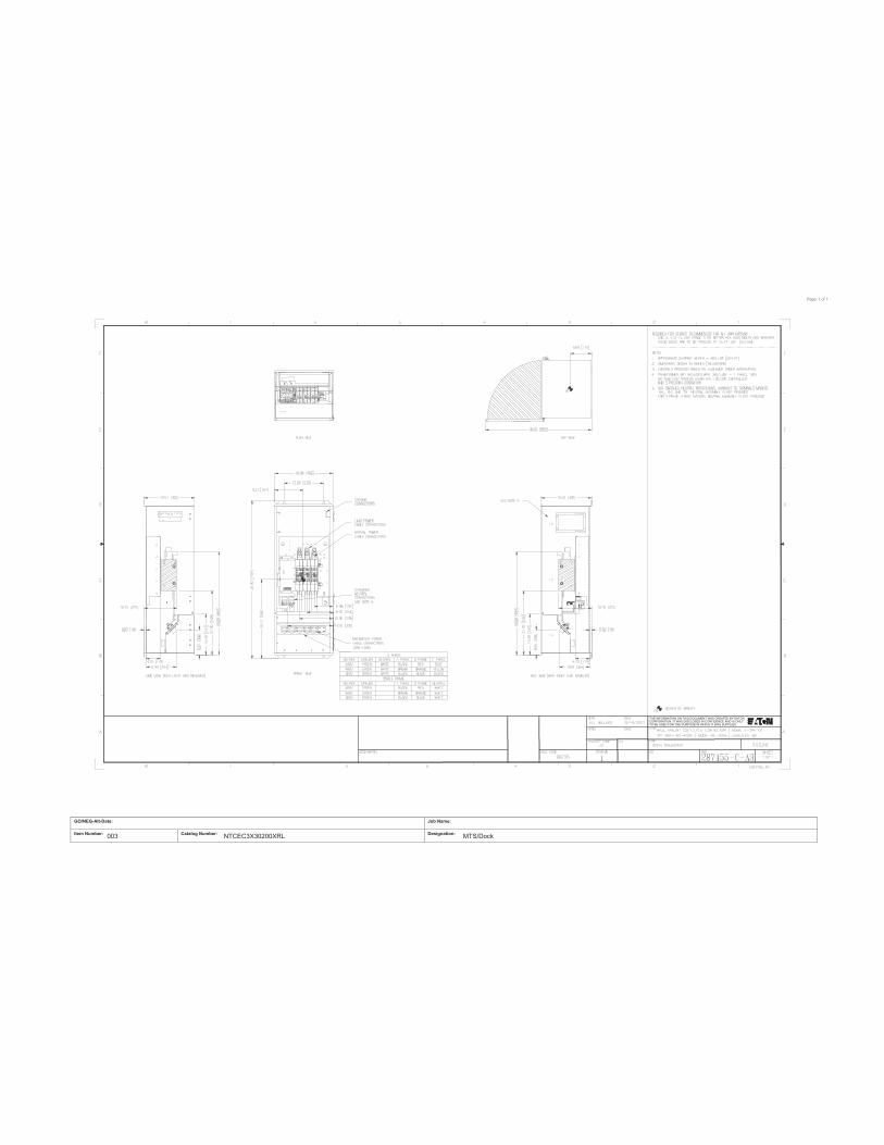
Product Family: Wall Mount Switch Type: Non Automatic Contactor 40A thru 1600A 480/277v, 60hz, 3 Phase, 4 Wire, 3 poles Transition Mode: Open Controller Type: Electromechanical Continuous Current: 200 Amps Withstand: 50kA spc/30kA (0.05 sec) Normal Source Terminals: (1) #6-250 CU/AL Emergency Source Terminals: (1) Cam-Lok Load Side Terminals: (1) #6-250 CU/AL Neutral Terminals: (3) 1/0-250 CU/AL
Standard Features: 12c, 12d, 12g, 12h, 14l, 14m, 15e, 15f, 42, 49c, Optional Features: No Optional Features Selected
Catalog No NTCEC3X30200XRL Designation MTS/Dock
Qty List of Materials 1 NTCEC3 3 Poles 200 Amps 1 Enclosure - Type-3R 1 Cam-Lok (Male, E1016 series) Color-Coded Nameplates 1 Cam-Lok Covers, Hinged Thermoplastic, Black 1 Cam-Lok Terminal (Emergency Source) withstand closing rating: 35kA
(0.05 secs) 1 Cam-Lok Ground Ampacity @ 100% 1 12c. Indicating Light Normal Source Connected 1 12d. Indicating Light Emergency Source Connected 1 12g. Indicating Light Normal Source Present 1 12h. Indicating Light Emergency Source Present 1 14l. Normal (S1) Source Present (2 Form C) 1 14m. Emergency (S2) Source Present (2 Form C) 1 15e. Normal (S1) Position Indication (1 Form C Micro Switch Outputs) 1 15f. Emergency (S2) Position Indication (1 Form C Micro Switch Outputs) 1 22. Ground Bar 1 42. IBC/CBC Seismic Qualified 1 49c. Multi-Tap Transformer
Eaton Selling Policy 25-000 applies.
All orders must be released for manufacture within 90 days of date of order entry. If approval drawings are required, drawings must be returned approved for release within 60 days of mailing. If drawings are not returned accordingly, and/or if shipment is delayed for any reason, the price of the order will increase by 1.0% per month or fraction thereof for the time the shipment is delayed.

Detail Bill of Material Page 4 of 4Project Name: Negotiation No: General Order No: Alternate No: 0000
Seller shall not be responsible for any failure to perform, or delay in performance of, its obligations resulting from the COVID-19 pandemic or any future epidemic, and Buyer shall not be entitled to any damages resulting thereof.

A
DETAIL A
Page: 1 of 1
GO/NEG-Alt-Date: Job Name:
Item Number: Catalog Number: Designation: 001 ATC3C5X40100XRU ATS-EM
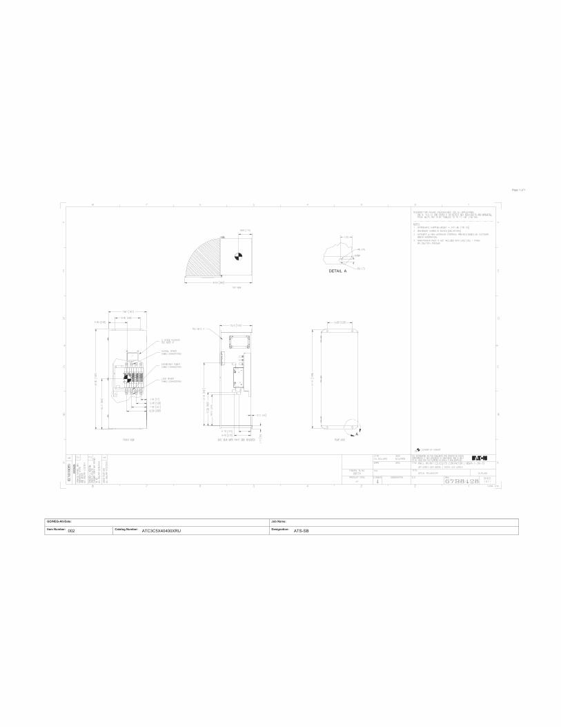
A
DETAIL A
Page: 1 of 1
GO/NEG-Alt-Date: Job Name:
Item Number: Catalog Number: Designation: 002 ATC3C5X40400XRU ATS-SB
THE INFORMATION ON THIS DOCUMENT WAS CREATED BY EATONCORPORATION. IT WAS DISCLOSED IN CONFIDENCE AND IS ONLYTO BE USED FOR THE PURPOSE IN WHICH IT WAS SUPPLIED.
Page: 1 of 1
GO/NEG-Alt-Date: Job Name:
Item Number: Catalog Number: Designation: 003 NTCEC3X30200XRL MTS/Dock
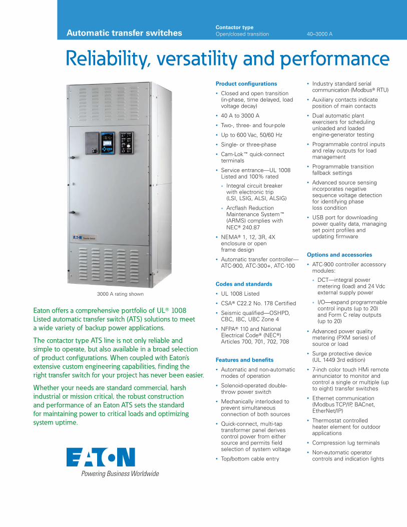
Reliability, versatility and performance
Eaton offers a comprehensive portfolio of UL� 1008
Listed automatic transfer switch (ATS) solutions to meet
a wide variety of backup power applications.
The contactor type ATS line is not only reliable and
simple to operate, but also available in a broad selection
of product configurations. When coupled with Eaton’s
extensive custom engineering capabilities, finding the
right transfer switch for your project has never been easier.
Whether your needs are standard commercial, harsh
industrial or mission critical, the robust construction
and performance of an Eaton ATS sets the standard
for maintaining power to critical loads and optimizing
system uptime.
Product configurations
• Closed and open transition (in-phase, time delayed, load voltage decay)
• 40 A to 3000 A
• Two-, three- and four-pole
• Up to 600 Vac, 50/60 Hz
• Single- or three-phase
• Cam-Lok� quick-connect terminals
• Service entrance—UL 1008 Listed and 100% rated
• Integral circuit breaker with electronic trip (LSI, LSIG, ALSI, ALSIG)
• Arcflash Reduction Maintenance System�(ARMS) complies withNEC� 240.87
• NEMA� 1, 12, 3R, 4X enclosure or open frame design
• Automatic transfer controller—ATC-900, ATC-300+, ATC-100
Codes and standards
• UL 1008 Listed
• CSA� C22.2 No. 178 Certified
• Seismic qualified—OSHPD, CBC, IBC, UBC Zone 4
• NFPA� 110 and National Electrical Code� (NEC�) Articles 700, 701, 702, 708
Features and benefits
• Automatic and non-automatic modes of operation
• Solenoid-operated double-throw power switch
• Mechanically interlocked to prevent simultaneous connection of both sources
• Quick-connect, multi-tap transformer panel derives control power from either source and permits field selection of system voltage
• Top/bottom cable entry
• Industry standard serial communication (Modbus� RTU)
• Auxiliary contacts indicate position of main contacts
• Dual automatic plant exercisers for scheduling unloaded and loaded engine-generator testing
• Programmable control inputs and relay outputs for load management
• Programmable transition fallback settings
• Advanced source sensing incorporates negative sequence voltage detection for identifying phase loss condition
• USB port for downloading power quality data, managing set point profiles and updating firmware
Options and accessories
• ATC-900 controller accessory modules:
• DCT—integral power metering (load) and 24 Vdc external supply power
• I/O—expand programmable control inputs (up to 20) and Form C relay outputs (up to 20)
• Advanced power quality metering (PXM series) of source or load
• Surge protective device(UL 1449 3rd edition)
• 7-inch color touch HMi remote annunciator to monitor and control a single or multiple (up to eight) transfer switches
• Ethernet communication (Modbus TCP/IP, BACnet, EtherNet/IP)
• Thermostat controlled heater element for outdoor applications
• Compression lug terminals
• Non-automatic operator controls and indication lights
3000 A rating shown
Automatic transfer switchesContactor typeOpen/closed transition 40–3000 A
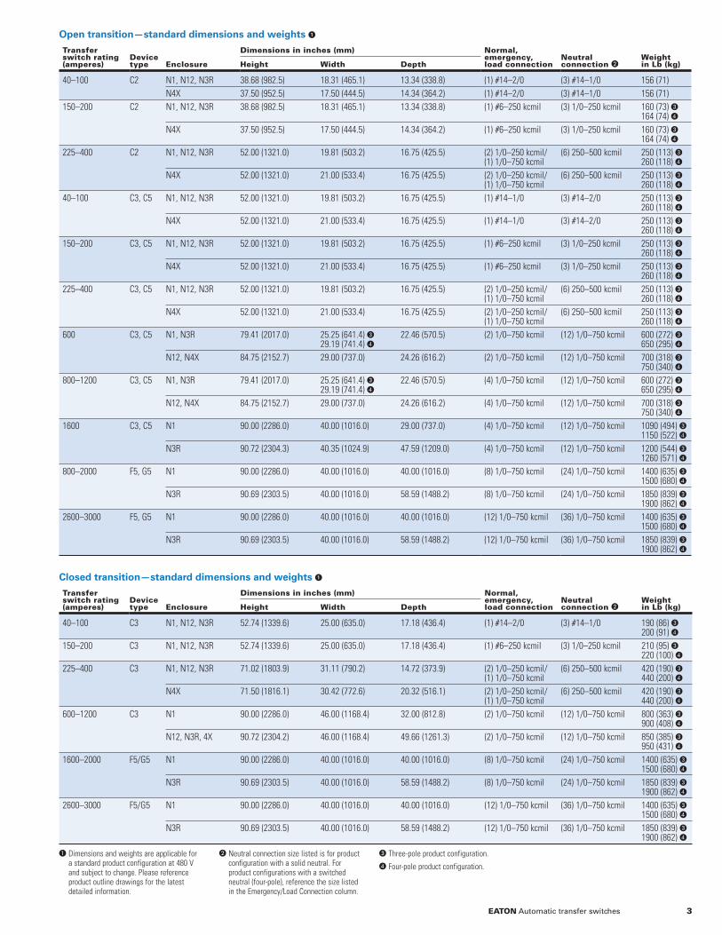
Open transition—standard dimensions and weights �
Transfer switch rating (amperes)
Device type Enclosure
Dimensions in inches (mm) Normal, emergency, load connection
Neutral connection �
Weight in Lb (kg)Height Width Depth
40–100 C2 N1, N12, N3R 38.68 (982.5) 18.31 (465.1) 13.34 (338.8) (1) #14–2/0 (3) #14–1/0 156 (71)
N4X 37.50 (952.5) 17.50 (444.5) 14.34 (364.2) (1) #14–2/0 (3) #14–1/0 156 (71)
150–200 C2 N1, N12, N3R 38.68 (982.5) 18.31 (465.1) 13.34 (338.8) (1) #6–250 kcmil (3) 1/0–250 kcmil 160 (73) �164 (74) �
N4X 37.50 (952.5) 17.50 (444.5) 14.34 (364.2) (1) #6–250 kcmil (3) 1/0–250 kcmil 160 (73) �164 (74) �
225–400 C2 N1, N12, N3R 52.00 (1321.0) 19.81 (503.2) 16.75 (425.5) (2) 1/0–250 kcmil/(1) 1/0–750 kcmil
(6) 250–500 kcmil 250 (113) �260 (118) �
N4X 52.00 (1321.0) 21.00 (533.4) 16.75 (425.5) (2) 1/0–250 kcmil/(1) 1/0–750 kcmil
(6) 250–500 kcmil 250 (113) �260 (118) �
40–100 C3, C5 N1, N12, N3R 52.00 (1321.0) 19.81 (503.2) 16.75 (425.5) (1) #14–1/0 (3) #14–2/0 250 (113) �260 (118) �
N4X 52.00 (1321.0) 21.00 (533.4) 16.75 (425.5) (1) #14–1/0 (3) #14–2/0 250 (113) �260 (118) �
150–200 C3, C5 N1, N12, N3R 52.00 (1321.0) 19.81 (503.2) 16.75 (425.5) (1) #6–250 kcmil (3) 1/0–250 kcmil 250 (113) �260 (118) �
N4X 52.00 (1321.0) 21.00 (533.4) 16.75 (425.5) (1) #6–250 kcmil (3) 1/0–250 kcmil 250 (113) �260 (118) �
225–400 C3, C5 N1, N12, N3R 52.00 (1321.0) 19.81 (503.2) 16.75 (425.5) (2) 1/0–250 kcmil/(1) 1/0–750 kcmil
(6) 250–500 kcmil 250 (113) �260 (118) �
N4X 52.00 (1321.0) 21.00 (533.4) 16.75 (425.5) (2) 1/0–250 kcmil/(1) 1/0–750 kcmil
(6) 250–500 kcmil 250 (113) �260 (118) �
600 C3, C5 N1, N3R 79.41 (2017.0) 25.25 (641.4) �29.19 (741.4) �
22.46 (570.5) (2) 1/0–750 kcmil (12) 1/0–750 kcmil 600 (272) �650 (295) �
N12, N4X 84.75 (2152.7) 29.00 (737.0) 24.26 (616.2) (2) 1/0–750 kcmil (12) 1/0–750 kcmil 700 (318) �750 (340) �
800–1200 C3, C5 N1, N3R 79.41 (2017.0) 25.25 (641.4) �29.19 (741.4) �
22.46 (570.5) (4) 1/0–750 kcmil (12) 1/0–750 kcmil 600 (272) �650 (295) �
N12, N4X 84.75 (2152.7) 29.00 (737.0) 24.26 (616.2) (4) 1/0–750 kcmil (12) 1/0–750 kcmil 700 (318) �750 (340) �
1600 C3, C5 N1 90.00 (2286.0) 40.00 (1016.0) 29.00 (737.0) (4) 1/0–750 kcmil (12) 1/0–750 kcmil 1090 (494) �1150 (522) �
N3R 90.72 (2304.3) 40.35 (1024.9) 47.59 (1209.0) (4) 1/0–750 kcmil (12) 1/0–750 kcmil 1200 (544) �1260 (571) �
800–2000 F5, G5 N1 90.00 (2286.0) 40.00 (1016.0) 40.00 (1016.0) (8) 1/0–750 kcmil (24) 1/0–750 kcmil 1400 (635) �1500 (680) �
N3R 90.69 (2303.5) 40.00 (1016.0) 58.59 (1488.2) (8) 1/0–750 kcmil (24) 1/0–750 kcmil 1850 (839) �1900 (862) �
2600–3000 F5, G5 N1 90.00 (2286.0) 40.00 (1016.0) 40.00 (1016.0) (12) 1/0–750 kcmil (36) 1/0–750 kcmil 1400 (635) �1500 (680) �
N3R 90.69 (2303.5) 40.00 (1016.0) 58.59 (1488.2) (12) 1/0–750 kcmil (36) 1/0–750 kcmil 1850 (839) �1900 (862) �
Closed transition—standard dimensions and weights �
Transfer switch rating (amperes)
Devicetype Enclosure
Dimensions in inches (mm) Normal, emergency,load connection
Neutralconnection �
Weightin Lb (kg)Height Width Depth
40–100 C3 N1, N12, N3R 52.74 (1339.6) 25.00 (635.0) 17.18 (436.4) (1) #14–2/0 (3) #14–1/0 190 (86) �200 (91) �
150–200 C3 N1, N12, N3R 52.74 (1339.6) 25.00 (635.0) 17.18 (436.4) (1) #6–250 kcmil (3) 1/0–250 kcmil 210 (95) �220 (100) �
225–400 C3 N1, N12, N3R 71.02 (1803.9) 31.11 (790.2) 14.72 (373.9) (2) 1/0–250 kcmil/(1) 1/0–750 kcmil
(6) 250–500 kcmil 420 (190) �440 (200) �
N4X 71.50 (1816.1) 30.42 (772.6) 20.32 (516.1) (2) 1/0–250 kcmil/(1) 1/0–750 kcmil
(6) 250–500 kcmil 420 (190) �440 (200) �
600–1200 C3 N1 90.00 (2286.0) 46.00 (1168.4) 32.00 (812.8) (2) 1/0–750 kcmil (12) 1/0–750 kcmil 800 (363) �900 (408) �
N12, N3R, 4X 90.72 (2304.2) 46.00 (1168.4) 49.66 (1261.3) (2) 1/0–750 kcmil (12) 1/0–750 kcmil 850 (385) �950 (431) �
1600–2000 F5/G5 N1 90.00 (2286.0) 40.00 (1016.0) 40.00 (1016.0) (8) 1/0–750 kcmil (24) 1/0–750 kcmil 1400 (635) �1500 (680) �
N3R 90.69 (2303.5) 40.00 (1016.0) 58.59 (1488.2) (8) 1/0–750 kcmil (24) 1/0–750 kcmil 1850 (839) �1900 (862) �
2600–3000 F5/G5 N1 90.00 (2286.0) 40.00 (1016.0) 40.00 (1016.0) (12) 1/0–750 kcmil (36) 1/0–750 kcmil 1400 (635) �1500 (680) �
N3R 90.69 (2303.5) 40.00 (1016.0) 58.59 (1488.2) (12) 1/0–750 kcmil (36) 1/0–750 kcmil 1850 (839) �1900 (862) �
� Dimensions and weights are applicable for a standard product configuration at 480 V and subject to change. Please reference product outline drawings for the latest detailed information.
� Neutral connection size listed is for product configuration with a solid neutral. For product configurations with a switched neutral (four-pole), reference the size listed in the Emergency/Load Connection column.
� Three-pole product configuration.
� Four-pole product configuration.
3EATON Automatic transfer switches
Eaton is a registered trademark.
All other trademarks are property of their respective owners.
Eaton1000 Eaton BoulevardCleveland, OH 44122United StatesEaton.com
© 2021 EatonAll Rights ReservedPrinted in USAPublication No. PA140015EN / Z24706January 2021
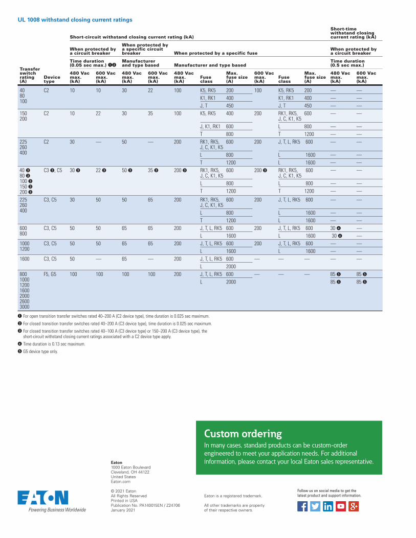
UL 1008 withstand closing current ratings
Transfer switch rating (A)
Device type
Short-circuit withstand closing current rating (kA)
Short-time withstand closing current rating (kA)
When protected by a circuit breaker
When protected by a specific circuit breaker When protected by a specific fuse
When protected by a circuit breaker
Time duration(0.05 sec max.) ��
Manufacturer and type based Manufacturer and type based
Time duration(0.5 sec max.)
480 Vac max. (kA)
600 Vac max. (kA)
480 Vac max. (kA)
600 Vac max. (kA)
480 Vac max. (kA)
Fuse class
Max. fuse size (A)
600 Vac max. (kA)
Fuse class
Max. fuse size (A)
480 Vac max. (kA)
600 Vac max. (kA)
4080100
C2 10 10 30 22 100 K5, RK5 200 100 K5, RK5 200 — —
K1, RK1 400 K1, RK1 400 — —
J, T 450 J, T 450 — —
150200
C2 10 22 30 35 100 K5, RK5 400 200 RK1, RK5, J, C, K1, K5
600 — —
J, K1, RK1 600 L 800 — —
T 800 T 1200 — —
225260400
C2 30 — 50 — 200 RK1, RK5, J, C, K1, K5
600 200 J, T, L, RK5 600 — —
L 800 L 1600 — —
T 1200 L 1600 — —
40 �80 �100 �150 �200 �
C3 �, C5 30 � 22 � 50 � 35 � 200 � RK1, RK5, J, C, K1, K5
600 200 � RK1, RK5, J, C, K1, K5
600 — —
L 800 L 800 — —
T 1200 T 1200 — —
225260 400
C3, C5 30 50 50 65 200 RK1, RK5, J, C, K1, K5
600 200 J, T, L, RK5 600 — —
L 800 L 1600 — —
T 1200 L 1600 — —
600800
C3, C5 50 50 65 65 200 J, T, L, RK5 600 200 J, T, L, RK5 600 30 � —
L 1600 L 1600 30 � —
1000 1200
C3, C5 50 50 65 65 200 J, T, L, RK5 600 200 J, T, L, RK5 600 — —
L 1600 L 1600 — —
1600 C3, C5 50 — 65 — 200 J, T, L, RK5 600 — — — — —
L 2000
8001000120016002000 2600 3000
F5, G5 100 100 100 100 200 J, T, L, RK5 600 — — — 85 � 85 �
L 2000 85 � 85 �
� For open transition transfer switches rated 40–200 A (C2 device type), time duration is 0.025 sec maximum.
� For closed transition transfer switches rated 40–200 A (C3 device type), time duration is 0.025 sec maximum.
� For closed transition transfer switches rated 40–100 A (C3 device type) or 150–200 A (C3 device type), the short-circuit withstand closing current ratings associated with a C2 device type apply.
� Time duration is 0.13 sec maximum.
� G5 device type only.
Custom orderingIn many cases, standard products can be custom-order
engineered to meet your application needs. For additional
information, please contact your local Eaton sales representative.
Follow us on social media to get the latest product and support information.
Volume 2—Commercial Distribution CA08100003E—February 2018 www.eaton.com V2-T5-5
5
5
5
5
5
5
5
5
5
5
5
5
5
5
5
5
5
5
5
5
5
5
5
5
5
5
5
5
5
5
5.1Transfer Switches
Transfer Switch Equipment—Product Overview
Product DescriptionEaton’s automatic transfer switches are reliable, rugged, versatile and compact assemblies for transferring essential loads and electrical distribution systems from one power source to another.
Transfer switches canbe supplied in separate enclosures for stand-alone applications or can be supplied as an integral component in the following equipment (see table below).
Product Type
Typical ApplicationsAll Eaton transfer switches are designed to meet the requirements set forth by UL 1008; however, all transfer switches are not created equal. You can be assured of safe and reliable operation from all types of transfer switches that Eaton offers.
Basic ComponentsThe three basic components of a transfer switch are:
● Power switching device to shift the load circuits to and from the power source
● Transfer logic controller to monitor the condition of the power sources and provide the control signals to the power switching device
● Control power source to supply operational power to the controller and switching device
Application DescriptionA transfer switch is a critical component of any emergency or standby power system. When the normal (preferred) source of power is lost, a transfer switch quickly and safely shifts the load circuit from the normal source of power to the emergency (alternate) source of power. This permits critical loads to continue running with minimal or no outage. After the normal source of power has been restored, the retransfer process returns the load circuit to the normal power source.
Transfer switches are available with different operational modes including:
● Manual● Non-automatic● Automatic● Bypass isolation● Maintenance bypass
Switch TypesManual transfer—This type of transfer is a non-automatic transfer switch manually initiated and manually operated. There is no motor operator or solenoid to initiate the transfer. The operator needs to open the enclosure door and operate the manual handle. Manual transfer is available only on a breaker-based design. Service entrance ratings are not available on manual transfer breaker-based designs.
Non-automatic transfer—This type of transfer is manually initiated, but electrically operated via the solenoid in a contactor-based design and the motor operator in a breaker-based design.
Automatic transfer—This type of transfer takes place automatically per the programmable settings in the ATS controller. The ATS controller senses source availability and when the programmed conditions are met, initiates a command to start the transfer including the generator start command (when transferring from a utility to a generator source). An automatic transfer switch can be configured to perform a utility-to-utility transfer or a generator-to-generator transfer (provided the ATS controller has this capability).
Bypass isolation transfer switch—This type of transfer switch includes an automatic transfer switch and also includes the bypass switch that allows the capability to transfer the load to the bypass switch without interrupting the power.
Maintenance bypass transfer switch—A maintenance bypass transfer switch is a non-automatic (manually initiated and electrically operated) initiated transfer switch used for specific applications for a UPS.
The power switching operation of transfer switches may be separated into the following transition modes:
Transition TypesOpen transition—This is a “break-before-make” transfer. There is a definite break in power as the load is disconnected from one source and connected to the other source.
Open in-phase transition—This is a “break-before-make” transfer. There is a definite break in power as the load is disconnected from one source and connected to the other source. The ATS controller allows the transfer only when the phase difference between the two sources is near zero.
Open in-phase with default to time delay neutral—break-before-make operation using an in-phase monitor for source synchronization. If the in-phase does not initiate a transfer within a programmabletime delay, then the transfer will default to a time delay neutral type of transfer.
Delayed transition—This is a “break-before-make” or open transition that also has a “center off” or neutral position with a programmable time delay setting for the neutral position. The transfer switch is either closed on Source 1, closed on Source 2, or in a center off, neutral position (not closed on either source).
Delayed transition with load voltage decay—This is a delayed transition with the optional feature to delay in the neutral position to point where the load voltage decays to a programmable voltage level. When the load voltage level reaches the programmable set point, the transfer from the neutral position initiates.
Closed transition—This is a “make-before-break” transfer. Both sources are connected to the load for less than 100ms before the break occurs. The two power sources have to be electrically synchronized in voltage, frequency and phase in order for a closed transition to be initiated by the automatic controller. Programmable setpoints allow the user to adjust frequency and voltage tolerances.
DescriptionSectionReference
UL 1558 Switchgear Vol. 3, Tab 4
UL 891 Switchboards Vol. 2, Tab 4
Motor Control Centers Vol. 3, Tab 3
Transfer Switch Equipment—Product Overview
Product Description
Typical Applications
Basic Components
Application Description
Switch Types
Non-automatic transfer—
Automatic transfer—
Transition TypesOpen transition—
to time delay neutral—Open in-phase with defaultp p
V2-T5-6 Volume 2—Commercial Distribution CA08100003E—February 2018 www.eaton.com
5
5
5
5
5
5
5
5
5
5
5
5
5
5
5
5
5
5
5
5
5
5
5
5
5
5
5
5
5
5
5.1 Transfer Switches
Transfer Switch Equipment—Product Overview
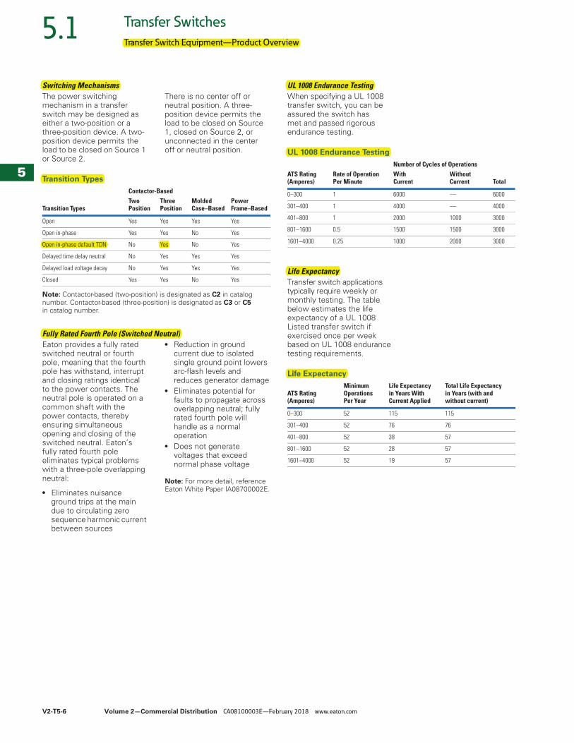
Switching MechanismsThe power switching mechanism in a transfer switch may be designed as either a two-position or a three-position device. A two-position device permits the load to be closed on Source 1 or Source 2.
There is no center off or neutral position. A three-position device permits the load to be closed on Source 1, closed on Source 2, or unconnected in the center off or neutral position.
Transition Types
Note: Contactor-based (two-position) is designated as C2 in catalog number. Contactor-based (three-position) is designated as C3 or C5in catalog number.
Fully Rated Fourth Pole (Switched Neutral)Eaton provides a fully rated switched neutral or fourth pole, meaning that the fourth pole has withstand, interrupt and closing ratings identical to the power contacts. The neutral pole is operated on a common shaft with the power contacts, thereby ensuring simultaneous opening and closing of the switched neutral. Eaton’s fully rated fourth pole eliminates typical problems with a three-pole overlapping neutral:
● Eliminates nuisance ground trips at the main due to circulating zero sequence harmonic current between sources
● Reduction in ground current due to isolated single ground point lowers arc-flash levels and reduces generator damage
● Eliminates potential for faults to propagate across overlapping neutral; fully rated fourth pole will handle as a normal operation
● Does not generate voltages that exceed normal phase voltage
Note: For more detail, reference Eaton White Paper IA08700002E.
Contactor-Based
Transition TypesTwo Position
Three Position
MoldedCase–Based
PowerFrame–Based
Open Yes Yes Yes Yes
Open in-phase Yes Yes No Yes
Open in-phase default TDN No Yes No Yes
Delayed time delay neutral No Yes Yes Yes
Delayed load voltage decay No Yes Yes Yes
Closed Yes Yes No Yes
UL 1008 Endurance TestingWhen specifying a UL 1008 transfer switch, you can be assured the switch has met and passed rigorous endurance testing.
UL 1008 Endurance Testing
Life ExpectancyTransfer switch applications typically require weekly or monthly testing. The table below estimates the life expectancy of a UL 1008 Listed transfer switch if exercised once per week based on UL 1008 endurance testing requirements.
Life Expectancy
Number of Cycles of OperationsATS Rating(Amperes)
Rate of OperationPer Minute
With Current
WithoutCurrent Total
0–300 1 6000 — 6000
301–400 1 4000 — 4000
401–800 1 2000 1000 3000
801–1600 0.5 1500 1500 3000
1601–4000 0.25 1000 2000 3000
ATS Rating(Amperes)
Minimum OperationsPer Year
Life Expectancyin Years With Current Applied
Total Life Expectancy in Years (with and without current)
0–300 52 115 115
301–400 52 76 76
401–800 52 38 57
801–1600 52 28 57
1601–4000 52 19 57
Transfer Switch Equipment—Product Overview
Switching Mechanisms
Transition Types
Open in-phase default TDN Yes
Fully Rated Fourth Pole (Switched Neutral)
UL 1008 Endurance Testing
UL 1008 Endurance Testing
Life Expectancy
Life Expectancy
Volume 2—Commercial Distribution CA08100003E—February 2018 www.eaton.com V2-T5-7
5
5
5
5
5
5
5
5
5
5
5
5
5
5
5
5
5
5
5
5
5
5
5
5
5
5
5
5
5
5
5.1Transfer Switches
Transfer Switch Equipment—Product Overview
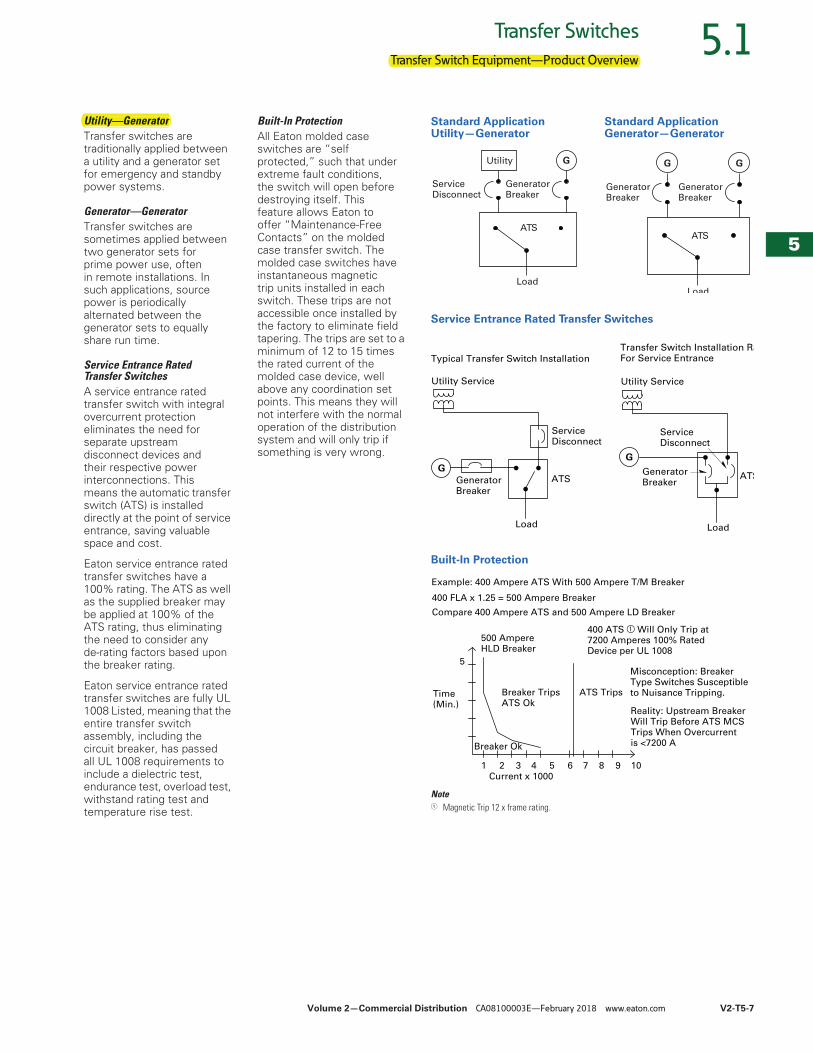
Utility—GeneratorTransfer switches are traditionally applied between a utility and a generator set for emergency and standby power systems.
Generator—GeneratorTransfer switches are sometimes applied between two generator sets for prime power use, often in remote installations. In such applications, source power is periodically alternated between the generator sets to equally share run time.
Service Entrance Rated Transfer SwitchesA service entrance rated transfer switch with integral overcurrent protection eliminates the need for separate upstream disconnect devices and their respective power interconnections. This means the automatic transfer switch (ATS) is installed directly at the point of service entrance, saving valuable space and cost.
Eaton service entrance rated transfer switches have a 100% rating. The ATS as well as the supplied breaker may be applied at 100% of the ATS rating, thus eliminating the need to consider any de-rating factors based upon the breaker rating.
Eaton service entrance rated transfer switches are fully UL 1008 Listed, meaning that the entire transfer switch assembly, including the circuit breaker, has passed all UL 1008 requirements to include a dielectric test, endurance test, overload test, withstand rating test and temperature rise test.
Built-In ProtectionAll Eaton molded case switches are “self protected,” such that under extreme fault conditions, the switch will open before destroying itself. This feature allows Eaton to offer “Maintenance-Free Contacts” on the molded case transfer switch. The molded case switches have instantaneous magnetic trip units installed in each switch. These trips are not accessible once installed by the factory to eliminate field tapering. The trips are set to a minimum of 12 to 15 times the rated current of the molded case device, well above any coordination set points. This means they will not interfere with the normal operation of the distribution system and will only trip if something is very wrong.
Standard Application Utility—Generator
Standard Application Generator—Generator
Service Entrance Rated Transfer Switches
Built-In Protection
Note1 Magnetic Trip 12 x frame rating.
ServiceDisconnect
Utility G
GeneratorBreaker
Load
ATS
G
GeneratorBreaker
G
GeneratorBreaker
Load
ATS
GeneratorBreaker
G
Load
ServiceDisconnect
ATS
Utility Service
G
GeneratorBreaker
Load
ATS
ServiceDisconnect
Utility Service
Typical Transfer Switch InstallationTransfer Switch Installation RaFor Service Entrance
400 FLA x 1.25 = 500 Ampere Breaker
Compare 400 Ampere ATS and 500 Ampere LD Breaker
Time(Min.)
5
1 2 3 4 5 6 7 8 9 10
Breaker Ok
400 ATS a Will Only Trip at 7200 Amperes 100% Rated Device per UL 1008
Breaker TripsATS Ok
ATS Trips
500 Ampere HLD Breaker
Current x 1000
Misconception: Breaker Type Switches Susceptible to Nuisance Tripping.
Example: 400 Ampere ATS With 500 Ampere T/M Breaker
Reality: Upstream Breaker Will Trip Before ATS MCS Trips When Overcurrent is <7200 A
Transfer Switch Equipment—Product Overview
Utility—Generator
V2-T5-8 Volume 2—Commercial Distribution CA08100003E—February 2018 www.eaton.com
5
5
5
5
5
5
5
5
5
5
5
5
5
5
5
5
5
5
5
5
5
5
5
5
5
5
5
5
5
5
5.2 Transfer Switches
Contactor-Based Transfer Switches
Contactor-Based Transfer Switch ContentsDescription Page
Contactor-Based Transfer SwitchOpen Transition, 40–1600 A
Features and Benefits . . . . . . . . . . . . . . . . . V2-T5-9Standards and Certifications . . . . . . . . . . . . V2-T5-10Catalog Number Selection . . . . . . . . . . . . . . V2-T5-10Technical Data and Specifications . . . . . . . . V2-T5-11Dimensions . . . . . . . . . . . . . . . . . . . . . . . . . V2-T5-12
Service Entrance Rated—Contactor-Based Transfer SwitchOpen Transition, Service Entrance
Rated, 40–1600 A . . . . . . . . . . . . . . . . . . . . . . . V2-T5-14Contactor-Based Automatic Transfer Switch
Closed Transition, 40–1200 A . . . . . . . . . . . . . . . . V2-T5-21Contactor-Based Transfer Switch
Open and Closed Transition, 1600–3000 A. . . . . . V2-T5-25
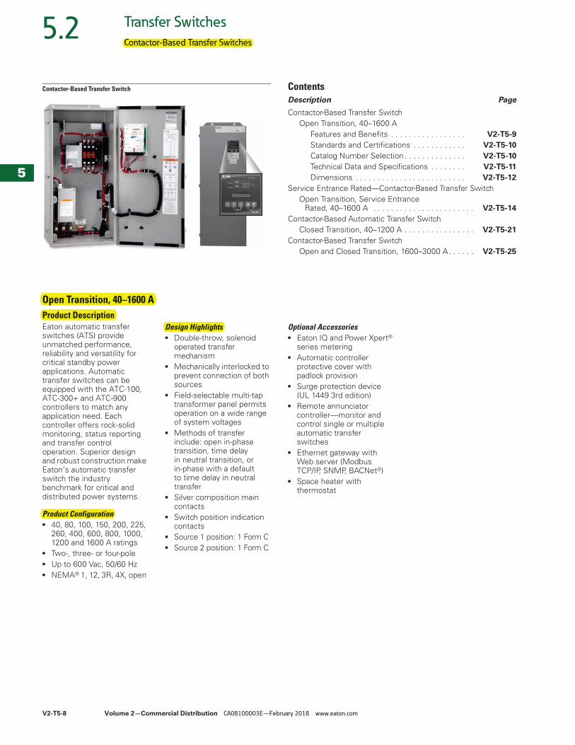
Open Transition, 40–1600 AProduct DescriptionEaton automatic transfer switches (ATS) provide unmatched performance, reliability and versatility for critical standby power applications. Automatic transfer switches can be equipped with the ATC-100, ATC-300+ and ATC-900 controllers to match any application need. Each controller offers rock-solid monitoring, status reporting and transfer control operation. Superior design and robust construction make Eaton’s automatic transfer switch the industry benchmark for critical and distributed power systems.
Product Configuration● 40, 80, 100, 150, 200, 225,
260, 400, 600, 800, 1000, 1200 and 1600 A ratings
● Two-, three- or four-pole● Up to 600 Vac, 50/60 Hz● NEMA® 1, 12, 3R, 4X, open
Design Highlights● Double-throw, solenoid
operated transfer mechanism
● Mechanically interlocked to prevent connection of both sources
● Field-selectable multi-tap transformer panel permits operation on a wide range of system voltages
● Methods of transfer include: open in-phase transition, time delay in neutral transition, or in-phase with a default to time delay in neutral transfer
● Silver composition main contacts
● Switch position indication contacts
● Source 1 position: 1 Form C● Source 2 position: 1 Form C
Optional Accessories● Eaton IQ and Power Xpert®
series metering● Automatic controller
protective cover with padlock provision
● Surge protection device (UL 1449 3rd edition)
● Remote annunciator controller—monitor and control single or multiple automatic transfer switches
● Ethernet gateway with Web server (Modbus TCP/IP, SNMP, BACNet®)
● Space heater with thermostat
Contactor-Based Transfer Switches
Open Transition, 40–1600 AProduct Description
Product Configuration
Design Highlights
Volume 2—Commercial Distribution CA08100003E—February 2018 www.eaton.com V2-T5-9
5
5
5
5
5
5
5
5
5
5
5
5
5
5
5
5
5
5
5
5
5
5
5
5
5
5
5
5
5
5
5.2Transfer Switches
Contactor-Based Transfer Switches
Features and Benefits
Standard and Optional Controller Features
Note1 Modbus TCP/IP option requires use of Modbus RTU port.
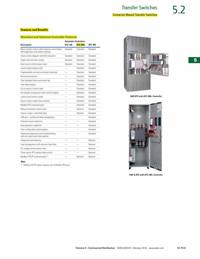
1600 ATS with ATC-300+ Controller
1200 A ATS with ATC-300+ Controller
Automatic ControllersDescription ATC-100 ATC-300+ ATC-900
Basic transfer control, plant exerciser, time delays, self diagnostics and system settings
Standard Standard Standard
Source mimic diagram with LED indication Standard Standard Standard
Engine test and start contact Standard Standard Standard
Dual source control power input Standard Standard Standard
Liquid crystal display (LCD) — Standard Standard
Programmable set points and plant exerciser — Standard Standard
Password protection — Standard Standard
Time stamped history and event log — Standard Standard
Time delay bypass — Standard Standard
Go to source 2 control input — Standard Standard
Pre-transfer and general alarm control outputs — Standard Standard
Lockout and monitor modes — Standard Standard
Source status output relay contacts — Standard Standard
Modbus RTU communication — Standard Standard
Manual retransfer control input — Optional Standard
Source 2 input / load shed input — Optional Standard
USB port—profile and data management — — Standard
Preferred source selection — — Standard
Dual generator capability — — Standard
User configurable inputs/outputs — — Standard
Advanced diagnostics and troubleshooting with pre-/post-event data capture
— — Standard
Integrated load metering — — Optional
Load management with selective load shed — — Optional
DC voltage control power input — — Optional
Three source ATS master/slave control — — Optional
Modbus TCP/IP communication 1 — Optional Optional
Contactor-Based Transfer Switches
Features and Benefits
Standard and Optional Controller Features
ATC-300+
V2-T5-10 Volume 2—Commercial Distribution CA08100003E—February 2018 www.eaton.com
5
5
5
5
5
5
5
5
5
5
5
5
5
5
5
5
5
5
5
5
5
5
5
5
5
5
5
5
5
5
5.2 Transfer Switches
Contactor-Based Transfer Switches
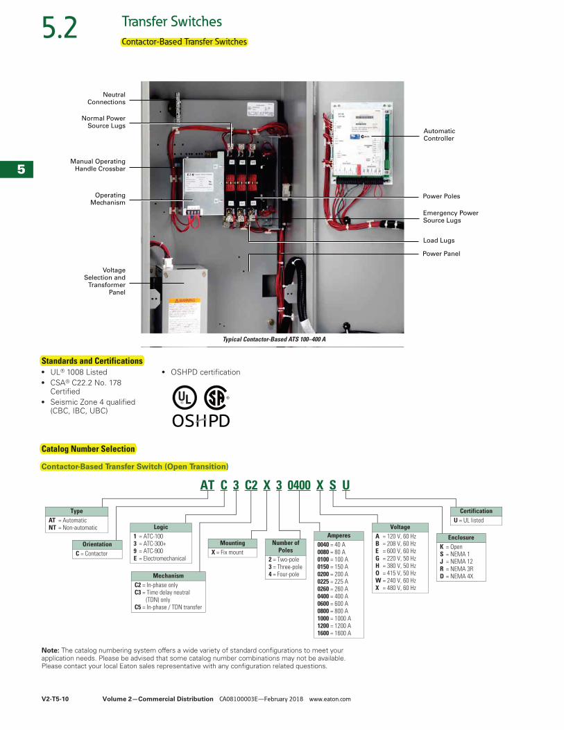
Standards and Certifications● UL® 1008 Listed● CSA® C22.2 No. 178
Certified● Seismic Zone 4 qualified
(CBC, IBC, UBC)
● OSHPD certification
Catalog Number Selection
Contactor-Based Transfer Switch (Open Transition)
Note: The catalog numbering system offers a wide variety of standard configurations to meet your application needs. Please be advised that some catalog number combinations may not be available. Please contact your local Eaton sales representative with any configuration related questions.
Power Poles
Power Panel
Load Lugs
Emergency PowerSource Lugs
AutomaticController
Normal PowerSource Lugs
Manual OperatingHandle Crossbar
OperatingMechanism
NeutralConnections
VoltageSelection and
TransformerPanel
Typical Contactor-Based ATS 100–400 A
AT C 3 C2 X 3 0400 X S U
TypeAT = AutomaticNT = Non-automatic
OrientationC = Contactor
Logic1 = ATC-100 3 = ATC-300+9 = ATC-900E = Electromechanical
MechanismC2 = In-phase onlyC3 = Time delay neutral
(TDN) onlyC5 = In-phase / TDN transfer
MountingX = Fix mount
Amperes0040 = 40 A0080 = 80 A0100 = 100 A0150 = 150 A0200 = 200 A0225 = 225 A0260 = 260 A0400 = 400 A0600 = 600 A0800 = 800 A1000 = 1000 A1200 = 1200 A1600 = 1600 A
VoltageA = 120 V, 60 HzB = 208 V, 60 HzE = 600 V, 60 HzG = 220 V, 50 HzH = 380 V, 50 HzO = 415 V, 50 HzW = 240 V, 60 HzX = 480 V, 60 Hz
EnclosureK = OpenS = NEMA 1J = NEMA 12R = NEMA 3RD = NEMA 4X
CertificationU = UL listed
Number ofPoles
2 = Two-pole3 = Three-pole4 = Four-pole
Contactor-Based Transfer Switches
Standards and Certifications
Catalog Number Selection
Contactor-Based Transfer Switch (Open Transition)
Volume 2—Commercial Distribution CA08100003E—February 2018 www.eaton.com V2-T5-11
5
5
5
5
5
5
5
5
5
5
5
5
5
5
5
5
5
5
5
5
5
5
5
5
5
5
5
5
5
5
5.2Transfer Switches
Contactor-Based Transfer Switches
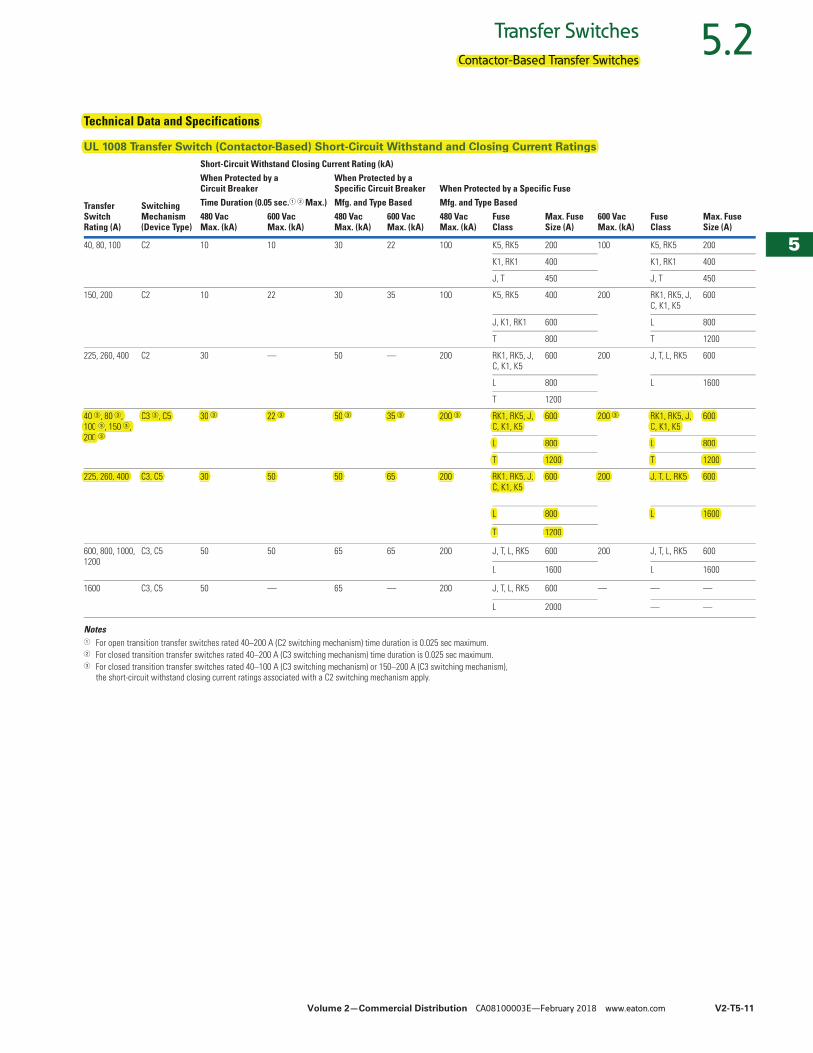
Technical Data and Specifications
UL 1008 Transfer Switch (Contactor-Based) Short-Circuit Withstand and Closing Current Ratings
Notes1 For open transition transfer switches rated 40–200 A (C2 switching mechanism) time duration is 0.025 sec maximum.2 For closed transition transfer switches rated 40–200 A (C3 switching mechanism) time duration is 0.025 sec maximum.3 For closed transition transfer switches rated 40–100 A (C3 switching mechanism) or 150–200 A (C3 switching mechanism),
the short-circuit withstand closing current ratings associated with a C2 switching mechanism apply.
Transfer Switch Rating (A)
Switching Mechanism (Device Type)
Short-Circuit Withstand Closing Current Rating (kA)When Protected by aCircuit Breaker
When Protected by aSpecific Circuit Breaker When Protected by a Specific Fuse
Time Duration (0.05 sec.1 2 Max.) Mfg. and Type Based Mfg. and Type BasedMax. Fuse Size (A)
600 Vac Max. (kA)
FuseClass
Max. Fuse Size (A)
480 Vac Max. (kA)
600 Vac Max. (kA)
480 Vac Max. (kA)
600 Vac Max. (kA)
480 Vac Max. (kA)
FuseClass
40, 80, 100 C2 10 10 30 22 100 K5, RK5 200 100 K5, RK5 200
K1, RK1 400 K1, RK1 400
J, T 450 J, T 450
150, 200 C2 10 22 30 35 100 K5, RK5 400 200 RK1, RK5, J, C, K1, K5
600
J, K1, RK1 600 L 800
T 800 T 1200
225, 260, 400 C2 30 — 50 — 200 RK1, RK5, J, C, K1, K5
600 200 J, T, L, RK5 600
L 800 L 1600
T 1200
40 3, 80 3, 100 3, 150 3, 200 3
C3 3, C5 30 3 22 3 50 3 35 3 200 3 RK1, RK5, J, C, K1, K5
600 200 3 RK1, RK5, J, C, K1, K5
600
L 800 L 800
T 1200 T 1200
225, 260, 400 C3, C5 30 50 50 65 200 RK1, RK5, J, C, K1, K5
600 200 J, T, L, RK5 600
L 800 L 1600
T 1200
600, 800, 1000, 1200
C3, C5 50 50 65 65 200 J, T, L, RK5 600 200 J, T, L, RK5 600
L 1600 L 1600
1600 C3, C5 50 — 65 — 200 J, T, L, RK5 600 — — —
L 2000 — —
Contactor-Based Transfer Switches
Technical Data and Specifications
UL 1008 Transfer Switch (Contactor-Based) Short-Circuit Withstand and Closing Current Ratings
40 3, 80 3, C3 3, C5 30 22 50 35 200 RK1, RK5, J, 600 200 RK1, RK5, J, 6003 3 3 3 3 3
100 3, 150 3, C, K1, K5 C, K1, K5200 3
L 800 L 800
T 1200 T 1200
225, 260, 400 C3, C5 30 50 50 65 200 RK1, RK5, J, 600 200 J, T, L, RK5 600C, K1, K5
L 800 L 1600
T 1200

Volume 2—Commercial Distribution CA08100003E—February 2018 www.eaton.com V2-T5-71
5
5
5
5
5
5
5
5
5
5
5
5
5
5
5
5
5
5
5
5
5
5
5
5
5
5
5
5
5
5
5.7Transfer Switches
Automatic Transfer Controllers
Automatic Transfer Controllers
ATC-100 ATC-300+ ATC-900
ContentsDescription Page
Automatic Transfer ControllersProduct Selection Guide
Automatic Transfer Controllers Feature Selection Chart . . . . . . . . . . . . . . . . . . . . . V2-T5-71
ATC-100 Controller . . . . . . . . . . . . . . . . . . . . . . . V2-T5-75ATC-300+ Controller . . . . . . . . . . . . . . . . . . . . . . V2-T5-77ATC-900 Controller . . . . . . . . . . . . . . . . . . . . . . . V2-T5-80Controller Replacement Guide . . . . . . . . . . . . . . V2-T5-91
Product Selection Guide
Automatic Transfer Controllers Feature Selection Chart
Feature Description ATC-100 ATC-300+ ATC-900
Transition
Open transition Standard Standard Standard
Closed transition Not available Not available Standard
Timers
Time delay normal to emergency (TDNE) Standard Standard Standard
Time delay engine start (TDES) Standard Standard Standard
Time delay emergency to normal (TDEN) Standard Standard Standard
Time delay engine cooldown (TDEC) Standard Standard Standard
Time delay emergency fail (TDEF) Standard Standard Standard
Engine/Generator Exerciser
Plant exerciser (PE) with fail-safe Selectable—OFF, 7-, 14-, 28-day interval fixed run time 15 minutes no load/load with fail-safe
Selectable—OFF, 7-, 14-, 28-day interval, 0–600 minutes, no load/load with fail-safe
Two independent exerciser modes—OFF, daily, 7-, 14-, 28-day interval or by calendar date (up to 12 independent calendar dates). Test operations include independent transfer time delays
Source 1 Sensing
All-phase undervoltage and underfrequency protection Standard Standard Standard
All-phase overvoltage and overfrequency protection Standard Standard Standard
Three-phase rotation sensing Not available Standard Standard
Three-phase voltage unbalance Not available Standard Standard
Source 2 Sensing
All-phase undervoltage and underfrequency protection Standard Standard Standard
All-phase overvoltage and overfrequency protection Standard Standard Standard
Three-phase rotation sensing Not available Standard Standard
Three-phase voltage unbalance Not available Standard Standard
Automatic Transfer Controllers
Product Selection Guide
Automatic Transfer Controllers Feature Selection Chart
ATC-300+
V2-T5-72 Volume 2—Commercial Distribution CA08100003E—February 2018 www.eaton.com
5
5
5
5
5
5
5
5
5
5
5
5
5
5
5
5
5
5
5
5
5
5
5
5
5
5
5
5
5
5
5.7 Transfer Switches
Automatic Transfer Controllers
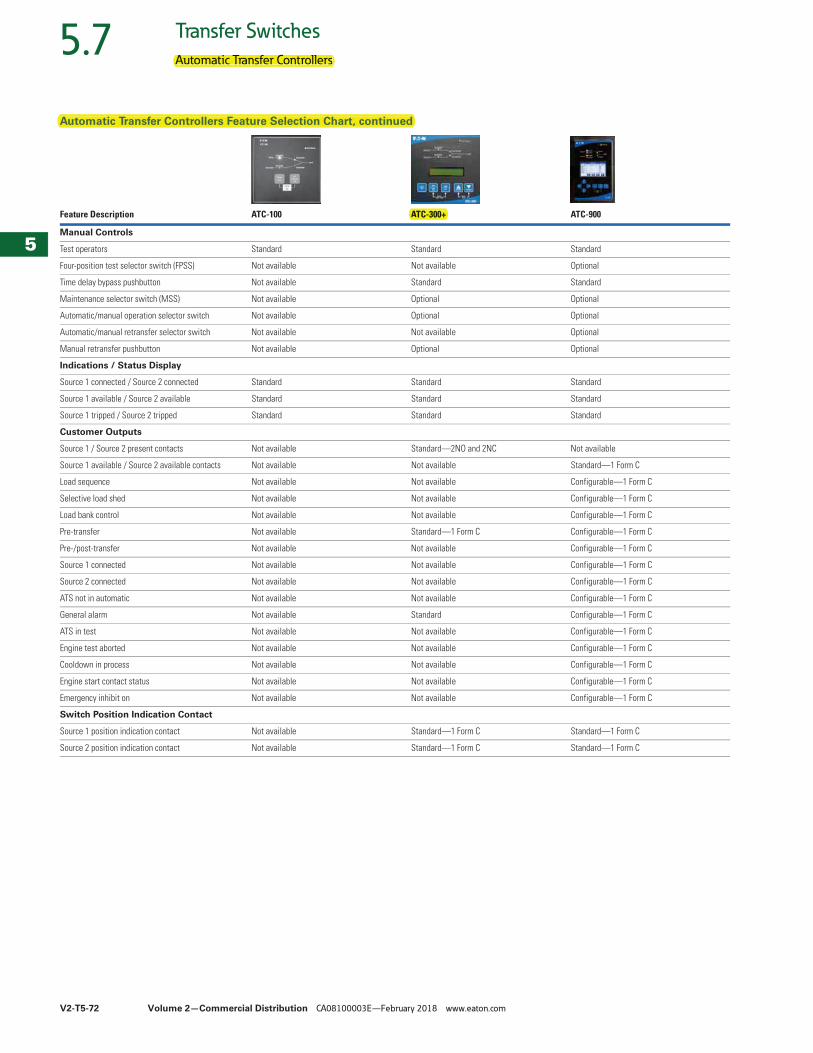
Automatic Transfer Controllers Feature Selection Chart, continued
Feature Description ATC-100 ATC-300+ ATC-900
Manual Controls
Test operators Standard Standard Standard
Four-position test selector switch (FPSS) Not available Not available Optional
Time delay bypass pushbutton Not available Standard Standard
Maintenance selector switch (MSS) Not available Optional Optional
Automatic/manual operation selector switch Not available Optional Optional
Automatic/manual retransfer selector switch Not available Not available Optional
Manual retransfer pushbutton Not available Optional Optional
Indications / Status Display
Source 1 connected / Source 2 connected Standard Standard Standard
Source 1 available / Source 2 available Standard Standard Standard
Source 1 tripped / Source 2 tripped Standard Standard Standard
Customer Outputs
Source 1 / Source 2 present contacts Not available Standard—2NO and 2NC Not available
Source 1 available / Source 2 available contacts Not available Not available Standard—1 Form C
Load sequence Not available Not available Configurable—1 Form C
Selective load shed Not available Not available Configurable—1 Form C
Load bank control Not available Not available Configurable—1 Form C
Pre-transfer Not available Standard—1 Form C Configurable—1 Form C
Pre-/post-transfer Not available Not available Configurable—1 Form C
Source 1 connected Not available Not available Configurable—1 Form C
Source 2 connected Not available Not available Configurable—1 Form C
ATS not in automatic Not available Not available Configurable—1 Form C
General alarm Not available Standard Configurable—1 Form C
ATS in test Not available Not available Configurable—1 Form C
Engine test aborted Not available Not available Configurable—1 Form C
Cooldown in process Not available Not available Configurable—1 Form C
Engine start contact status Not available Not available Configurable—1 Form C
Emergency inhibit on Not available Not available Configurable—1 Form C
Switch Position Indication Contact
Source 1 position indication contact Not available Standard—1 Form C Standard—1 Form C
Source 2 position indication contact Not available Standard—1 Form C Standard—1 Form C
Automatic Transfer Controllers
Automatic Transfer Controllers Feature Selection Chart, continued
ATC-300+
Volume 2—Commercial Distribution CA08100003E—February 2018 www.eaton.com V2-T5-73
5
5
5
5
5
5
5
5
5
5
5
5
5
5
5
5
5
5
5
5
5
5
5
5
5
5
5
5
5
5
5.7Transfer Switches
Automatic Transfer Controllers
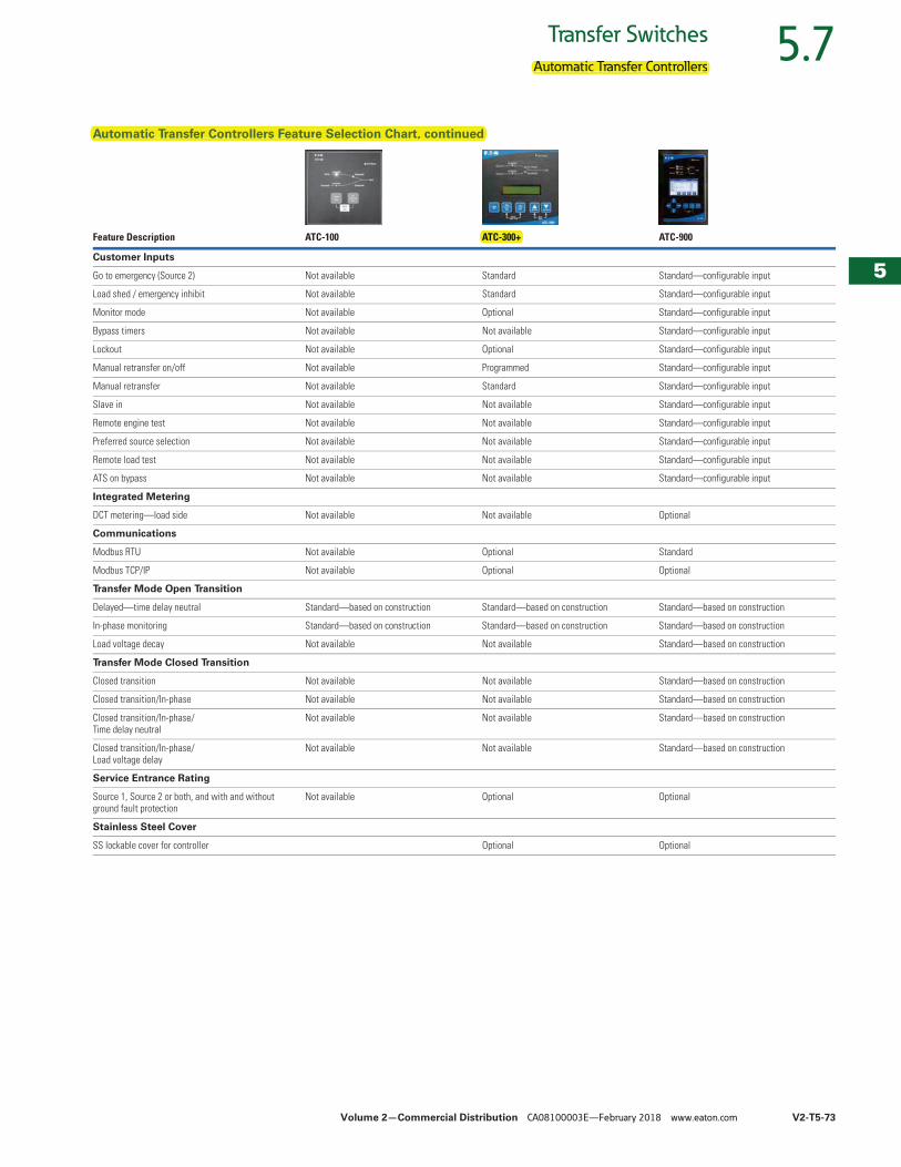
Automatic Transfer Controllers Feature Selection Chart, continued
Feature Description ATC-100 ATC-300+ ATC-900
Customer Inputs
Go to emergency (Source 2) Not available Standard Standard—configurable input
Load shed / emergency inhibit Not available Standard Standard—configurable input
Monitor mode Not available Optional Standard—configurable input
Bypass timers Not available Not available Standard—configurable input
Lockout Not available Optional Standard—configurable input
Manual retransfer on/off Not available Programmed Standard—configurable input
Manual retransfer Not available Standard Standard—configurable input
Slave in Not available Not available Standard—configurable input
Remote engine test Not available Not available Standard—configurable input
Preferred source selection Not available Not available Standard—configurable input
Remote load test Not available Not available Standard—configurable input
ATS on bypass Not available Not available Standard—configurable input
Integrated Metering
DCT metering—load side Not available Not available Optional
Communications
Modbus RTU Not available Optional Standard
Modbus TCP/IP Not available Optional Optional
Transfer Mode Open Transition
Delayed—time delay neutral Standard—based on construction Standard—based on construction Standard—based on construction
In-phase monitoring Standard—based on construction Standard—based on construction Standard—based on construction
Load voltage decay Not available Not available Standard—based on construction
Transfer Mode Closed Transition
Closed transition Not available Not available Standard—based on construction
Closed transition/In-phase Not available Not available Standard—based on construction
Closed transition/In-phase/Time delay neutral
Not available Not available Standard—based on construction
Closed transition/In-phase/Load voltage delay
Not available Not available Standard—based on construction
Service Entrance Rating
Source 1, Source 2 or both, and with and without ground fault protection
Not available Optional Optional
Stainless Steel Cover
SS lockable cover for controller Optional Optional
Automatic Transfer Controllers
Automatic Transfer Controllers Feature Selection Chart, continued
ATC-300+
V2-T5-74 Volume 2—Commercial Distribution CA08100003E—February 2018 www.eaton.com
5
5
5
5
5
5
5
5
5
5
5
5
5
5
5
5
5
5
5
5
5
5
5
5
5
5
5
5
5
5
5.7 Transfer Switches
Automatic Transfer Controllers
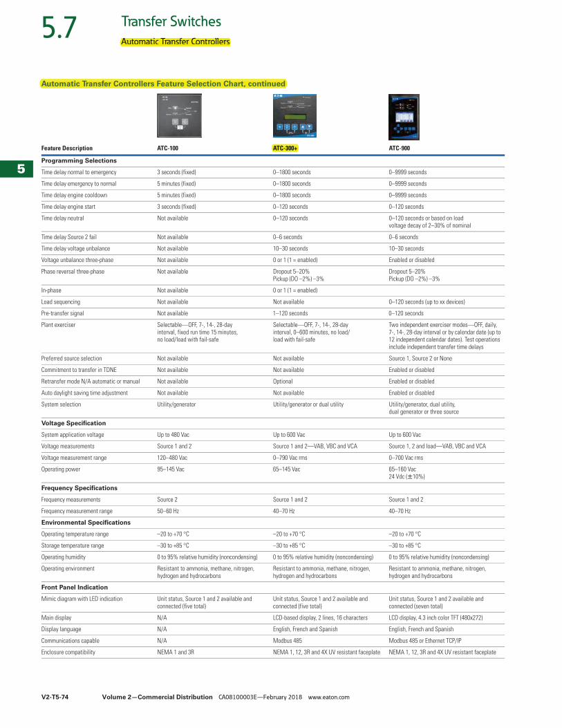
Automatic Transfer Controllers Feature Selection Chart, continued
Feature Description ATC-100 ATC-300+ ATC-900
Programming Selections
Time delay normal to emergency 3 seconds (fixed) 0–1800 seconds 0–9999 seconds
Time delay emergency to normal 5 minutes (fixed) 0–1800 seconds 0–9999 seconds
Time delay engine cooldown 5 minutes (fixed) 0–1800 seconds 0–9999 seconds
Time delay engine start 3 seconds (fixed) 0–120 seconds 0–120 seconds
Time delay neutral Not available 0–120 seconds 0–120 seconds or based on load voltage decay of 2–30% of nominal
Time delay Source 2 fail Not available 0–6 seconds 0–6 seconds
Time delay voltage unbalance Not available 10–30 seconds 10–30 seconds
Voltage unbalance three-phase Not available 0 or 1 (1 = enabled) Enabled or disabled
Phase reversal three-phase Not available Dropout 5–20%Pickup (DO –2%) –3%
Dropout 5–20%Pickup (DO –2%) –3%
In-phase Not available 0 or 1 (1 = enabled)
Load sequencing Not available Not available 0–120 seconds (up to xx devices)
Pre-transfer signal Not available 1–120 seconds 0–120 seconds
Plant exerciser Selectable—OFF, 7-, 14-, 28-day interval, fixed run time 15 minutes, no load/load with fail-safe
Selectable—OFF, 7-, 14-, 28-day interval, 0–600 minutes, no load/load with fail-safe
Two independent exerciser modes—OFF, daily, 7-, 14-, 28-day interval or by calendar date (up to 12 independent calendar dates). Test operations include independent transfer time delays
Preferred source selection Not available Not available Source 1, Source 2 or None
Commitment to transfer in TDNE Not available Not available Enabled or disabled
Retransfer mode N/A automatic or manual Not available Optional Enabled or disabled
Auto daylight saving time adjustment Not available Not available Enabled or disabled
System selection Utility/generator Utility/generator or dual utility Utility/generator, dual utility, dual generator or three source
Voltage Specification
System application voltage Up to 480 Vac Up to 600 Vac Up to 600 Vac
Voltage measurements Source 1 and 2 Source 1 and 2—VAB, VBC and VCA Source 1, 2 and load—VAB, VBC and VCA
Voltage measurement range 120–480 Vac 0–790 Vac rms 0–700 Vac rms
Operating power 95–145 Vac 65–145 Vac 65–160 Vac24 Vdc (W10%)
Frequency Specifications
Frequency measurements Source 2 Source 1 and 2 Source 1 and 2
Frequency measurement range 50–60 Hz 40–70 Hz 40–70 Hz
Environmental Specifications
Operating temperature range –20 to +70 °C –20 to +70 °C –20 to +70 °C
Storage temperature range –30 to +85 °C –30 to +85 °C –30 to +85 °C
Operating humidity 0 to 95% relative humidity (noncondensing) 0 to 95% relative humidity (noncondensing) 0 to 95% relative humidity (noncondensing)
Operating environment Resistant to ammonia, methane, nitrogen, hydrogen and hydrocarbons
Resistant to ammonia, methane, nitrogen, hydrogen and hydrocarbons
Resistant to ammonia, methane, nitrogen, hydrogen and hydrocarbons
Front Panel Indication
Mimic diagram with LED indication Unit status, Source 1 and 2 available and connected (five total)
Unit status, Source 1 and 2 available and connected (five total)
Unit status, Source 1 and 2 available and connected (seven total)
Main display N/A LCD-based display, 2 lines, 16 characters LCD display, 4.3 inch color TFT (480x272)
Display language N/A English, French and Spanish English, French and Spanish
Communications capable N/A Modbus 485 Modbus 485 or Ethernet TCP/IP
Enclosure compatibility NEMA 1 and 3R NEMA 1, 12, 3R and 4X UV resistant faceplate NEMA 1, 12, 3R and 4X UV resistant faceplate
Automatic Transfer Controllers
Automatic Transfer Controllers Feature Selection Chart, continued
ATC-300+
Volume 2—Commercial Distribution CA08100003E—February 2018 www.eaton.com V2-T5-77
5
5
5
5
5
5
5
5
5
5
5
5
5
5
5
5
5
5
5
5
5
5
5
5
5
5
5
5
5
5
5.7Transfer Switches
Automatic Transfer Controllers
ATC-300+ Controller ContentsDescription Page
Automatic Transfer ControllersProduct Selection Guide . . . . . . . . . . . . . . . . . . . V2-T5-71ATC-100 ControllerATC-300+ Controller . . . . . . . . . . . . . . . . . . . . . . V2-T5-77
Standards and Certifications . . . . . . . . . . . . V2-T5-79Technical Data and Specifications . . . . . . . . V2-T5-79
ATC-900 Controller . . . . . . . . . . . . . . . . . . . . . . . V2-T5-80Controller Replacement Guide . . . . . . . . . . . . . . V2-T5-91
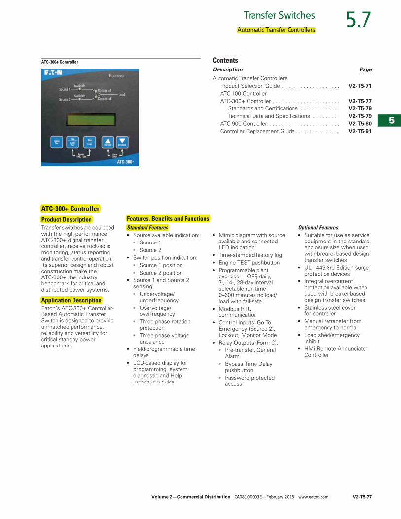
ATC-300+ ControllerProduct DescriptionTransfer switches are equipped with the high-performance ATC-300+ digital transfer controller, receive rock-solid monitoring, status reporting and transfer control operation. Its superior design and robust construction make the ATC-300+ the industry benchmark for critical and distributed power systems.
Application DescriptionEaton’s ATC-300+ Controller-Based Automatic Transfer Switch is designed to provide unmatched performance, reliability and versatility for critical standby power applications.
Standard Features● Source available indication:
● Source 1● Source 2
● Switch position indication:● Source 1 position ● Source 2 position
● Source 1 and Source 2 sensing:● Undervoltage/
underfrequency● Overvoltage/
overfrequency● Three-phase rotation
protection● Three-phase voltage
unbalance● Field-programmable time
delays● LCD-based display for
programming, system diagnostic and Help message display
● Mimic diagram with source available and connected LED indication
● Time-stamped history log● Engine TEST pushbutton● Programmable plant
exerciser—OFF, daily, 7-, 14-, 28-day interval selectable run time 0–600 minutes no load/load with fail-safe
● Modbus RTU communication
● Control Inputs: Go To Emergency (Source 2), Lockout, Monitor Mode
● Relay Outputs (Form C):● Pre-transfer, General
Alarm● Bypass Time Delay
pushbutton● Password protected
access
Optional Features● Suitable for use as service
equipment in the standard enclosure size when used with breaker-based design transfer switches
● UL 1449 3rd Edition surge protection devices
● Integral overcurrent protection available when used with breaker-based design transfer switches
● Stainless steel cover for controller
● Manual retransfer from emergency to normal
● Load shed/emergency inhibit
● HMi Remote Annunciator Controller
Features, Benefits and Functions
Automatic Transfer Controllers
ATC-300+ ControllerProduct Description
Application Description
Features, Benefits and FunctionsStandard Features

V2-T5-78 Volume 2—Commercial Distribution CA08100003E—February 2018 www.eaton.com
5
5
5
5
5
5
5
5
5
5
5
5
5
5
5
5
5
5
5
5
5
5
5
5
5
5
5
5
5
5
5.7 Transfer Switches
Automatic Transfer Controllers
ATC-300+ Front Panel Display and Button Functions
The following set points are programmable if the corresponding feature is programmed.
ATC-300+ Programming Features/Set Points 1
Note1 Complete list of programming selections found in IB01602009E.
Set Point Set Point Units Description Range Factory Default
TDES Minutes: seconds Time delay engine start 0–120 seconds 0:03
TDNE Minutes: seconds Time delay normal to emergency 0–1800 seconds 0:00
TDEN Minutes: seconds Time delay emergency to normal 0–1800 seconds 5:00
TDEC Minutes: seconds Time delay engine cool-off 0–1800 seconds 5:00
TDN Minutes: seconds Time delay neutral 0–120 seconds 0:00
PLANT EXER Days Plant exerciser programming Off, daily, 7-day, 14-day or 28 day Off
TEST MODE — Test Mode 0, 1 or 2 (0 = no load engine test, 1 = load engine test, 2 = disabled) 0
TER Hours: minutes Engine run test time 0–600 min 5:00
TPRE Minutes: seconds Pre-transfer delay timer 0–120 sec 0:00
PHASES — Three-phase or single-phase 1 or 3 As ordered
VOLT UNBAL Volts Voltage unbalanced 0 or 1 (1 = enabled) 1
UNBAL DROP % Percent Percent for unbalanced voltage dropout 5–20% of phase voltage unbalance 20%
UNBAL PICK % Percent Percent for unbalanced voltage pickup Dropout minus (UNBAL DROP % –2) to 3% 10%
UNBAL DELAY Seconds Unbalanced delay timer 10–30 0:20
TDEF Seconds Time delay emergency fail timer 0–6 sec 6
PHASE REV — Phase reversal OFF, ABC or CBA OFF
LCD DisplayProvides visual indication of monitored parameters (voltage, frequency), status, set points, history, time/date.
Source 1, Source 2, and LoadColored LED lights show status of both Sources and Load.
Increase/Decrease Allows user to adjust values when programming controller set points.
Step ButtonPermits user to scroll through information and set points.
Help Pressing the Help button in any function mode will bring up display messages, explanations and prompts to assist the operator.
Engine Test ButtonPressing this button initiates an engine test.
Lamp Test Enter
Unit Status LED
Bypass Time DelaysPressing the Enter and Help pushbuttons simultaneously reduces the active programmed time delay to zero to simplify test procedures.
Automatic Transfer Controllers
ATC-300+ Front Panel Display and Button Functions
ATC-300+ Programming Features/Set Points
Volume 2—Commercial Distribution CA08100003E—February 2018 www.eaton.com V2-T5-79
5
5
5
5
5
5
5
5
5
5
5
5
5
5
5
5
5
5
5
5
5
5
5
5
5
5
5
5
5
5
5.7Transfer Switches
Automatic Transfer Controllers
Standards and Certifications● UL listed component● Meets intent of
UL 991, 1008● Meets IEC 1000-4-2, 1000-
4-3, 1000-4-4, 1000-4-5, 1000-4-6, 1000-4-11
● Meets CISPR 11, Class A● Complies with FCC Part 15,
Class A
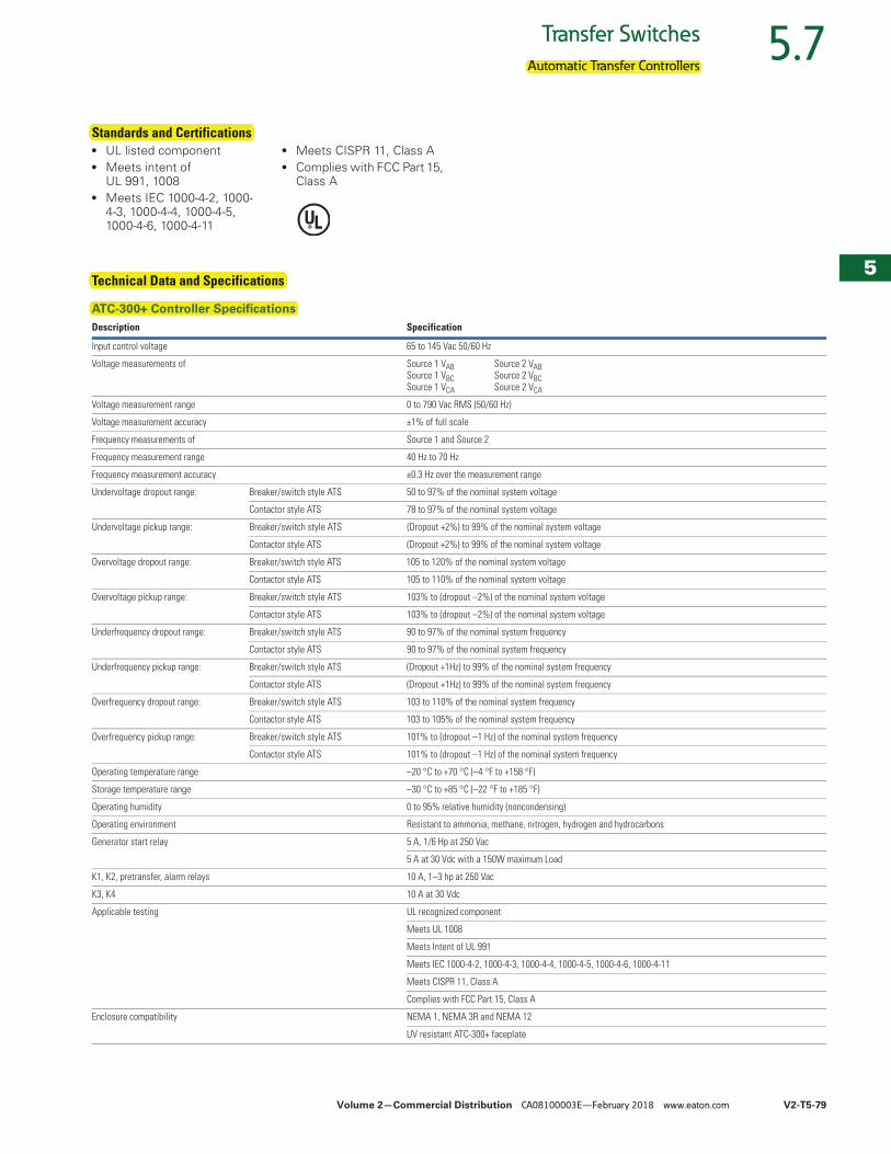
Technical Data and Specifications
ATC-300+ Controller SpecificationsDescription Specification
Input control voltage 65 to 145 Vac 50/60 Hz
Voltage measurements of Source 1 VAB Source 2 VABSource 1 VBC Source 2 VBCSource 1 VCA Source 2 VCA
Voltage measurement range 0 to 790 Vac RMS (50/60 Hz)
Voltage measurement accuracy ±1% of full scale
Frequency measurements of Source 1 and Source 2
Frequency measurement range 40 Hz to 70 Hz
Frequency measurement accuracy ±0.3 Hz over the measurement range
Undervoltage dropout range: Breaker/switch style ATS 50 to 97% of the nominal system voltage
Contactor style ATS 78 to 97% of the nominal system voltage
Undervoltage pickup range: Breaker/switch style ATS (Dropout +2%) to 99% of the nominal system voltage
Contactor style ATS (Dropout +2%) to 99% of the nominal system voltage
Overvoltage dropout range: Breaker/switch style ATS 105 to 120% of the nominal system voltage
Contactor style ATS 105 to 110% of the nominal system voltage
Overvoltage pickup range: Breaker/switch style ATS 103% to (dropout –2%) of the nominal system voltage
Contactor style ATS 103% to (dropout –2%) of the nominal system voltage
Underfrequency dropout range: Breaker/switch style ATS 90 to 97% of the nominal system frequency
Contactor style ATS 90 to 97% of the nominal system frequency
Underfrequency pickup range: Breaker/switch style ATS (Dropout +1Hz) to 99% of the nominal system frequency
Contactor style ATS (Dropout +1Hz) to 99% of the nominal system frequency
Overfrequency dropout range: Breaker/switch style ATS 103 to 110% of the nominal system frequency
Contactor style ATS 103 to 105% of the nominal system frequency
Overfrequency pickup range: Breaker/switch style ATS 101% to (dropout –1 Hz) of the nominal system frequency
Contactor style ATS 101% to (dropout –1 Hz) of the nominal system frequency
Operating temperature range –20 °C to +70 °C (–4 °F to +158 °F)
Storage temperature range –30 °C to +85 °C (–22 °F to +185 °F)
Operating humidity 0 to 95% relative humidity (noncondensing)
Operating environment Resistant to ammonia, methane, nitrogen, hydrogen and hydrocarbons
Generator start relay 5 A, 1/6 Hp at 250 Vac
5 A at 30 Vdc with a 150W maximum Load
K1, K2, pretransfer, alarm relays 10 A, 1–3 hp at 250 Vac
K3, K4 10 A at 30 Vdc
Applicable testing UL recognized component
Meets UL 1008
Meets Intent of UL 991
Meets IEC 1000-4-2, 1000-4-3, 1000-4-4, 1000-4-5, 1000-4-6, 1000-4-11
Meets CISPR 11, Class A
Complies with FCC Part 15, Class A
Enclosure compatibility NEMA 1, NEMA 3R and NEMA 12
UV resistant ATC-300+ faceplate
Automatic Transfer Controllers
Standards and Certifications
Technical Data and Specifications
ATC-300+ Controller Specifications
V2-T5-116 Volume 2—Commercial Distribution CA08100003E—February 2018 www.eaton.com
5
5
5
5
5
5
5
5
5
5
5
5
5
5
5
5
5
5
5
5
5
5
5
5
5
5
5
5
5
5
5.9 Transfer Switches
Standard and Optional Features
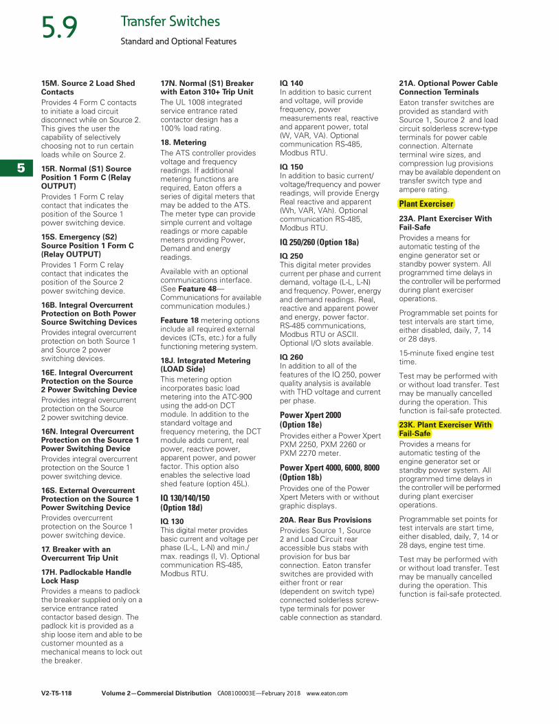
Feature DescriptionTimers1. Time Delay Normal to Emergency (TDNE)Provides a time delay to allow for the generator to warm up before transferring the load to the emergency source. Timing begins only after the Emergency Source becomes available and is deemed good based on the programmable voltage and frequency set points in the controller.
2. Time Delay Engine Start (TDES)Provides a time delay before initiating the generator start cycle. This is to account for momentary power outages or voltage fluctuations of the normal source. Provides a Form C contact to the generator starter circuit.
3. Time Delay Emergency to Normal (TDEN)Provides a time delay of the retransfer operation to permit stabilization of the normal source. Timing begins only after the normal source becomes available and is deemed good based on the programmable voltage and frequency set points in the controller. This function is fail-safe protected.
4. Time Delay Engine Cooldown (TDEC)Provides a time delay before initiating the generator stop cycle after the retransfer operation. This allows the generator to cool down by running unloaded. Timing begins on completion of the retransfer cycle.
Source 2 Sensing5. Source 2—Monitoring and ProtectionProvides monitoring and protection based on the Source 2 voltage and/or frequency set points. All Feature 5 monitoring and protection functions are fail-safe operations.
5H. Three-Phase Rotation ProtectionProvides three-phase reversal sensing in order to protect against transferring to an out-of-phase source. The controllerwill treat the opposite source as unavailable if the sources are out of phase, based on programmable set points in the controller.
5J. All-Phase Undervoltage/Underfrequency ProtectionProvides undervoltage/underfrequency monitoring and protection based on programmable set points in the controller.
5K. All-Phase Overvoltage/Overfrequency ProtectionProvides overvoltage/overfrequency monitoring and protection based on programmable set points in the controller.
5L. Three-Phase Voltage Unbalance/Phase LossProvides phase loss detection from blown fuses on the Source 2 supply circuit.
5M. All Phase Voltage Phase LossProvides phase loss detection on the Source 2 supply circuit.
6B. Test OperatorsAutomatic transfer switches are provided with a controller faceplate test pushbutton that simulates a loss of the Source 1 as standard. All programmed time delays (TDNE, TDEN, etc.) will be performed as part of the test. Engine run time of the test is equal to the plant exerciser programmed set point. All tests are fail-safe protected.
6C. Remote Engine Test (INPUT)Provides an input to initiate a test to simulate a loss of the Source 1 as standard. All programmed time delays (TDNE, TDEN, etc.) will be performed as part of the test. Engine run time of the test is equal to the plant exerciser programmed set point. All tests are fail-safe protected. The test is initiated via remote momentary contact closure.
6D. Maintained 2 Position Test SwitchProvides a door-mounted 2-position test switch marked “Auto” and “Test”. Available with ATC-900 controller only.
6H. 4-Position Test Selector Switch (FPSS)Provides a door-mounted 4-position, maintained contact selector switch marked “Auto,” “Test,” “Engine Start,” and “Off.” The FPSS is fail-safe protected, except for the “Off Position.” Transfer switch operation is determined by the switch position. Transfer switch operations are as follows:
“Auto”—Automatic operation mode.
“Test”—A load test is performed until the switch is moved to another position.
“Engine Start”—A no-load test is performed until the switch is moved to another position.
“Off”—The automatic transfer controller and engine start contact are disabled. A white pilot light is provided to indicate that the FPSS is in the “Off” position.
7. Time Delay Emergency Fail (TDEF)Provides a time delay that prevents a connected emergency source from being declared “unavailable” based on the customer’s set points. This is to account for momentary generator fluctuations. If the Source 2 remains in a failed state, then 0.5 seconds after the TDEF timer expires the transfer switch will proceed with the programmed sequence for retransfer if Source 1 is available. This time delay is only implemented when Source 2 is a generator.
Note: This feature is also enabled when large loads cause generator output to drop below customer set points.
8. Time Delay Bypass Push-buttonProvides a momentary contact pushbutton to bypass the TDNE (Feature 1) and/or TDEN (Feature 3) time delays. The Time Delay Bypass Pushbutton contact, when closed, will reduce any or all of the programmed time delay to zero. Must be executed when TDNE or TDEN timer is displayed on the controller.
8C. Bypass Time Delay Emergency to Normal (TDEN)
8D. Bypass Time Delay Normal to Emergency (TDNE)
8E. Bypass TDNE/TDEN (INPUT)Provides input to bypass the TDNE (Feature 1) and/or TDEN (Feature 2) time delays. The Time Delay Bypass Pushbutton contact, when closed, will reduce any or all of the programmed time delay to zero. Must be executed when TDNE or TDEN timer is displayed on the controller. The bypass time delay feature is initiated via remote momentary contact closure.
Standard and Optional Features
Feature DescriptionTimers1. Time Delay Normal toyEmergency (TDNE)
2. Time Delay Engine Start(TDES)
3. Time Delay Emergency toyNormal (TDEN)
4. Time Delay Engine y gCooldown (TDEC)
Source 2 Sensing5. Source 2—Monitoringand Protection
Protection5H. Three-Phase Rotation
5J. All-Phase Undervoltage/gUnderfrequency Protection
5K. All-Phase Overvoltage/gOverfrequency Protection
5L. Three-Phase VoltagegUnbalance/Phase Loss
6B. Test Operators
7. Time Delay EmergencyFail (TDEF)
8. Time Delay Bypass Push-button
8C. Bypass Time Delay yp yEmergency to Normalg(TDEN)
8D. Bypass Time Delayyp yNormal to Emergency(TDNE)
Volume 2—Commercial Distribution CA08100003E—February 2018 www.eaton.com V2-T5-117
5
5
5
5
5
5
5
5
5
5
5
5
5
5
5
5
5
5
5
5
5
5
5
5
5
5
5
5
5
5
5.9Transfer Switches
Standard and Optional Features
8F. Bypass Timers—External Pushbutton InputProvides an input from a customer supplied external pushbutton to bypass or reduce the programmed time delays to zero for TDEN and TDNE.
9B. Maintenance Selector Switch (MSS)Provides a 2-position, maintained contact selector switch marked “Operate” and “Disable.” When the MSS is placed in the “Disable” position, the controller logic will be disconnected from the transfer motor circuit. The MSS is placed in the “Operate” position for normal automatic operation.
9C. Monitor Mode Selector SwitchProvides a 2-position selector switch to enable/disable Monitor Mode on the controller. When enabled, the controller will monitor the availability, connected state and voltage conditions and will initiate a transfer.
10. Preferred Source SelectorProvides a means to designate either Source 1 or Source 2 as the “Preferred” source. The “Preferred” source is the source that the transfer switch will connect the load to if it is available.
Note: This is a programmable software feature not an actual switch.
10A. Preferred Source Selector (INPUT)Provides a means to designate either Source 1 or Source 2 as the “Preferred” source using a remote contact or device panel mounted contact closure. The “Preferred” source is the source that the transfer switch will connect the load to if it is available.
10B. Preferred Source SelectorProvides a programmable source selector for use on systems comprised of dual utility or utility and engine/ generator power sources.
10C. Preferred Source Selector with Selector SwitchProvides a means to designate either Source 1 or Source 2 as the “Preferred” source via device panel mounted selector switch control. The “Preferred” source is the source that the transfer switch will connect the load to if it is available.
10D. Preferred Source SelectorProvides a programmable source selector for use on systems comprised of dual engine/generator power sources. (Dual engine starting circuits are provided.)
12C. Source 1—Load ConnectedProvides a green indication that indicates the load is connected to Source 1 when lit.
12D. Source 2—Load ConnectedProvides a red indication that indicates the load is connected to Source 2when lit.
12G. Source 1—PresentProvides a white or amber indication “Depending on the Controller” that Source 1 has power; however, this does not indicate whether Source 1 is acceptable.
12H. Source 2—PresentProvides an amber indication that Source 2has power; however, this does not indicate whether Source 2is acceptable.
Overcurrent Trip IndicationAvailable only with integral overcurrent protection (Feature 16) (shown on automatic transfer controller display).
12L. Source 1 Trip IndicationThe automatic transfer controller display will read “Lockout” if the Source 1 circuit breaker is in the “tripped” position.
12M. Source 2 Trip IndicationThe automatic transfer controller display will read “Lockout” if the Source 2 circuit breaker is in the “tripped” position.
14. Relay Auxiliary Contacts14C. Source 1 PresentProvides 4 Form C relay auxiliary contacts. The relay is energized when Source 1 is present.
14D. Source 2 PresentProvides 4 Form C relay auxiliary contacts. The relay is energized when Source 2 is present.
14E. Source 1 AvailableProvides 1 Form C relay auxiliary contact. The relay is energized when Source 1 is available and within the controller’s programmable set points.
14F. Source 2 AvailableProvides 1 Form C relay auxiliary contact. The relay is energized when Source 2 is available and within the controller’s programmable set points.
14G. Source 1 PresentProvides 2 Form C relay auxiliary contacts. The relay is energized when Source 1 is present.
14H. Source 2 PresentProvides 2 Form C relay auxiliary contacts. The relay is energized when Source 2 is present.
14J. Source 1 PresentProvides 4 Form C relay auxiliary contacts. The relay is energized when Source 1 is present.
14K. Source 2 PresentProvides 4 Form C relay auxiliary contacts. The relay is energized when Source 2 is present.
14L. Source 1 PresentProvides 2 Form C relay auxiliary contacts. The relay is energized when Source 1 is present.
14M. Source 2 PresentProvides 2 Form C relay auxiliary contacts. The relay is energized when Source 2 is present.
15. Switch Position Indication ContactProvides a contact that indicates if the power switching device is in the “open” or “closed” position.
15E. Source 1 Position Indication ContactProvides 1 Form C contact that indicates the position of the Source 1 power switching device.
15F. Source 2 Position Indication ContactProvides 1 Form C contact that indicates the position of the Source 2 power switching device.
15G. Source 1 Position Indication ContactProvides 3 Form C contact that indicates the position of Source 1 power switching device.
15H. Source 2 Position Indication ContactProvides 3 Form C contact that indicates the position of Source 1 power switching device.
15K. Normal (S1) Breaker Position Indication 1 Form C (Output)Provides 1 Form C contact of the breaker indicating the breaker position.
15L. Normal (S1) Breaker Position Indication 2 Form C (Output)Provides 2 Form C contact of the breaker indicating the breaker position.
9C. Monitor Mode SelectorSwitch
12C. Source 1—LoadConnected
12D. Source 2—Load Connected
12G. Source 1—Present
12H. Source 2—Present
14. Relay Auxiliary Contacts
14L. Source 1 Present
14M. Source 2 Present
15. Switch PositionIndication Contact
15E. Source 1 PositionIndication Contact
15F. Source 2 PositionIndication Contact
V2-T5-118 Volume 2—Commercial Distribution CA08100003E—February 2018 www.eaton.com
5
5
5
5
5
5
5
5
5
5
5
5
5
5
5
5
5
5
5
5
5
5
5
5
5
5
5
5
5
5
5.9 Transfer Switches
Standard and Optional Features
15M. Source 2 Load Shed ContactsProvides 4 Form C contacts to initiate a load circuit disconnect while on Source 2. This gives the user the capability of selectively choosing not to run certain loads while on Source 2.
15R. Normal (S1) Source Position 1 Form C (Relay OUTPUT)Provides 1 Form C relay contact that indicates the position of the Source 1 power switching device.
15S. Emergency (S2) Source Position 1 Form C (Relay OUTPUT)Provides 1 Form C relay contact that indicates the position of the Source 2power switching device.
16B. Integral Overcurrent Protection on Both Power Source Switching DevicesProvides integral overcurrent protection on both Source 1 and Source 2 power switching devices.
16E. Integral Overcurrent Protection on the Source 2 Power Switching DeviceProvides integral overcurrent protection on the Source 2 power switching device.
16N. Integral Overcurrent Protection on the Source 1 Power Switching DeviceProvides integral overcurrent protection on the Source 1 power switching device.
16S. External Overcurrent Protection on the Source 1 Power Switching DeviceProvides overcurrent protection on the Source 1 power switching device.
17. Breaker with an Overcurrent Trip Unit
17H. Padlockable Handle Lock HaspProvides a means to padlock the breaker supplied only on a service entrance rated contactor based design. The padlock kit is provided as a ship loose item and able to be customer mounted as a mechanical means to lock out the breaker.
17N. Normal (S1) Breaker with Eaton 310+ Trip UnitThe UL 1008 integrated service entrance rated contactor design has a 100% load rating.
18. MeteringThe ATS controller provides voltage and frequency readings. If additional metering functions are required, Eaton offers a series of digital meters that may be added to the ATS. The meter type can provide simple current and voltage readings or more capable meters providing Power, Demand and energy readings.
Available with an optional communications interface. (See Feature 48—Communications for available communication modules.)
Feature 18 metering options include all required external devices (CTs, etc.) for a fully functioning metering system.
18J. Integrated Metering (LOAD Side)This metering option incorporates basic load metering into the ATC-900 using the add-on DCT module. In addition to the standard voltage and frequency metering, the DCT module adds current, real power, reactive power, apparent power, and power factor. This option also enables the selective load shed feature (option 45L).
IQ 130/140/150 (Option 18d)
IQ 130This digital meter provides basic current and voltage per phase (L-L, L-N) and min./max. readings (I, V). Optional communication RS-485, Modbus RTU.
IQ 140In addition to basic current and voltage, will provide frequency, power measurements real, reactive and apparent power, total (W, VAR, VA). Optional communication RS-485, Modbus RTU.
IQ 150In addition to basic current/voltage/frequency and power readings, will provide Energy Real reactive and apparent (Wh, VAR, VAh). Optional communication RS-485, Modbus RTU.
IQ 250/260 (Option 18a)
IQ 250This digital meter provides current per phase and current demand, voltage (L-L, L-N) and frequency. Power, energy and demand readings. Real, reactive and apparent power and energy, power factor. RS-485 communications, Modbus RTU or ASCII. Optional I/O slots available.
IQ 260In addition to all of the features of the IQ 250, power quality analysis is available with THD voltage and current per phase.
Power Xpert 2000 (Option 18e)Provides either a Power Xpert PXM 2250, PXM 2260 or PXM 2270 meter.
Power Xpert 4000, 6000, 8000 (Option 18b)Provides one of the Power Xpert Meters with or without graphic displays.
20A. Rear Bus ProvisionsProvides Source 1, Source 2 and Load Circuit rear accessible bus stabs with provision for bus bar connection. Eaton transfer switches are provided with either front or rear (dependent on switch type) connected solderless screw-type terminals for power cable connection as standard.
21A. Optional Power Cable Connection TerminalsEaton transfer switches are provided as standard with Source 1, Source 2 and load circuit solderless screw-type terminals for power cable connection. Alternate terminal wire sizes, and compression lug provisions may be available dependent on transfer switch type and ampere rating.
Plant Exerciser
23A. Plant Exerciser With Fail-SafeProvides a means for automatic testing of the engine generator set or standby power system. All programmed time delays in the controller will be performedduring plant exerciser operations.
Programmable set points for test intervals are start time, either disabled, daily, 7, 14 or 28 days.
15-minute fixed engine test time.
Test may be performed with or without load transfer. Test may be manually cancelled during the operation. This function is fail-safe protected.
23K. Plant Exerciser With Fail-SafeProvides a means for automatic testing of the engine generator set or standby power system. All programmed time delays in the controller will be performedduring plant exerciser operations.
Programmable set points for test intervals are start time, either disabled, daily, 7, 14 or 28 days, engine test time.
Test may be performed with or without load transfer. Test may be manually cancelled during the operation. This function is fail-safe protected.
Plant Exerciser
23K. Plant Exerciser With Fail-Safe
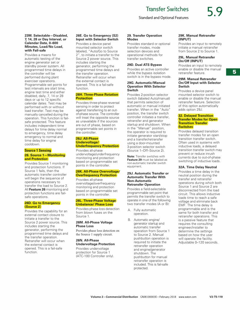
Volume 2—Commercial Distribution CA08100003E—February 2018 www.eaton.com V2-T5-119
5
5
5
5
5
5
5
5
5
5
5
5
5
5
5
5
5
5
5
5
5
5
5
5
5
5
5
5
5
5
5.9Transfer Switches
Standard and Optional Features
23M. Selectable—Disabled, 7, 14, 28 or Day Interval, or Calendar Date, 0–600 Minutes, Load/No Load, with Fail-safeProvides a means for automatic testing of the engine generator set or standby power system. All programmed time delays in the controller will be performed during plant exerciser operations. Programmable set points for test intervals are start time, engine test time and either disabled, daily, 7, 14 or 28 days or up to 12 specific calendar dates. Test may be performed with or without load transfer. Test may be manually cancelled during the operation. This function is fail-safe protected. This feature includes independent time delays for time delay normal to emergency, time delay emergency to normal andtime delay for engine cooldown.
Source 1 Sensing26. Source 1—Monitoring and ProtectionProvides Source 1 monitoring and protection functions. If Source 1 fails, then the automatic transfer controller will begin the sequence of operations necessary to transfer the load to Source 2. All Feature 26 monitoring and protection functions are fail-safe operations.
26D. Go to Emergency (Source 2)Provides the capability for an external contact closure to initiate a transfer to the Source 2 power source. This includes starting the generator, performing the programmed time delays and the transfer operation. Retransfer will occur when the external contact is opened. This is a fail-safe function.
26E. Go to Emergency (S2) Input with Selector SwitchProvides a device panel mounted selector switch labeled, “Auto/Go to Source 2”, to initiate a transfer to the Source 2 power source. This includes starting the generator, performing the programmed time delays and the transfer operation. Retransfer will occur when the external contact is opened. This is a fail-safe function.
26H. Three-Phase Rotation ProtectionProvides three-phase reversal sensing in order to protect against transferring to an out-of-phase source. The controllerwill treat the opposite source as unavailable if the sources are out of phase, based on programmable set points in the controller.
26J. All-Phase Undervoltage/Underfrequency ProtectionProvides all-phase undervoltage/underfrequency monitoring and protection based on programmable set points in the controller.
26K. All-Phase Overvoltage/Overfrequency ProtectionProvides all-phase overvoltage/overfrequency monitoring and protection based on programmable set points in the controller.
26L. Three-Phase Voltage Unbalance/ Phase LossProvides phase loss detection from blown fuses on the Source 1.
26M. All-Phase Voltage Phase LossProvides phase loss detection on the Source 1 supply circuit.
26N. All-Phase Undervoltage ProtectionProvides undervoltage protection for Source 1 (ATC-100 Controller only).
29. Transfer Operation ModesProvides standard or optional transfer modes, mode selection devices and operational methods for transfer switches.
29D. Dual ATS BypassProvides an active controller while the bypass isolation switch is in the bypass mode.
29G. Automatic/Manual Operation With Selector SwitchProvides 2-position selector switch (labeled Auto/manual) that permits selection of automatic or manual initiated transfer. When in the “Auto” position, the transfer switch controller initiates a transfer, retransfer and generator startup and shutdown. When in the “Manual” position, the operator is required to initiate generator start/stop and a transfer/retransfer using a door-mounted 3-position selector switch (Source 1–Off–Source 2).
Note: Transfer switches with Feature 29 must be labeled as non-automatic transfer switch equipment.
29J. Automatic Transfer or Automatic Transfer With Non-Automatic Retransfer OperationProvides a field-selectable programmable set point that permits the transfer switch to operate in one of the following two transfer modes (A or B):
A. Fully automatic operation.
B. Automatic engine/generator startup and automatic transfer operation from Source 1 to Source 2. Manual pushbutton operation is required to initiate the retransfer operation and engine/generator shutdown. The pushbutton for manual retransfer operation is included. This is fail-safe protected.
29K. Manual Retransfer (INPUT)Provides an input to remotely initiate a manual retransfer from Source 2 to Source 1.
29L. Manual Retransfer On/Off (INPUT)Provides an input to remotely enable or disable the manual retransfer feature.
29M. Manual Retransfer On/Off Input with Selector SwitchProvides a device panel mounted selector switch to enable or disable the manual retransfer feature. Selection of this option automatically adds option 29J.
32. Delayed Transition Transfer Modes for Open Transition Transfer SwitchesProvides delayed transition transfer modes for an open transition transfer switch. Often used in systems with inductive loads, a delayed transition transfer switch may prevent or reduce inrush currents due to out-of-phase switching of inductive loads.
32A. Time Delay NeutralProvides a time delay in the neutral position during the transfer and retransfer operations during which both Source 1 and Source 2 are disconnected from the load circuit. This allows inductive loads time to reach a safe voltage and eliminate back EMF. The time delay is programmable and is the same for both transfer and retransfer operations. This is a passive feature that requires the consulting engineer/installer to determine the settings based on how the user will operate the facility. Adjustable 0–120 seconds.
Source 1 Sensing26. Source 1—Monitoringand Protection
26D. Go to Emergency(Source 2)
26H. Three-Phase RotationProtection
26J. All-Phase Undervoltage/gUnderfrequency Protection
Overfrequency Protection26K. All-Phase Overvoltage/g
26L. Three-Phase Voltage gUnbalance/ Phase Loss
32. Delayed TransitionyTransfer Modes for OpenTransition TransferSwitches
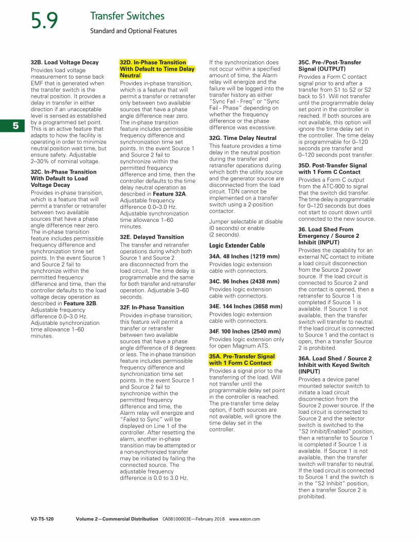
V2-T5-120 Volume 2—Commercial Distribution CA08100003E—February 2018 www.eaton.com
5
5
5
5
5
5
5
5
5
5
5
5
5
5
5
5
5
5
5
5
5
5
5
5
5
5
5
5
5
5
5.9 Transfer Switches
Standard and Optional Features
32B. Load Voltage DecayProvides load voltage measurement to sense back EMF that is generated when the transfer switch is the neutral position. It provides a delay in transfer in either direction if an unacceptable level is sensed as established by a programmed set point. This is an active feature that adapts to how the facility is operating in order to minimize neutral position wait time, but ensure safety. Adjustable 2–30% of nominal voltage.
32C. In-Phase Transition With Default to Load Voltage DecayProvides in-phase transition, which is a feature that will permit a transfer or retransfer between two available sources that have a phase angle difference near zero. The in-phase transition feature includes permissible frequency difference and synchronization time set points. In the event Source 1 and Source 2 fail to synchronize within the permitted frequency difference and time, then the controller defaults to the load voltage decay operation as described in Feature 32B. Adjustable frequency difference 0.0–3.0 Hz. Adjustable synchronization time allowance 1–60 minutes.
32D. In-Phase Transition With Default to Time Delay NeutralProvides in-phase transition, which is a feature that will permit a transfer or retransfer only between two available sources that have a phase angle difference near zero. The in-phase transition feature includes permissible frequency difference and synchronization time set points. In the event Source 1 and Source 2 fail to synchronize within the permitted frequency difference and time, then the controller defaults to the time delay neutral operation as described in Feature 32A. Adjustable frequency difference 0.0–3.0 Hz. Adjustable synchronization time allowance 1–60 minutes.
32E. Delayed TransitionThe transfer and retransfer operations during which both Source 1 and Source 2are disconnected from the load circuit. The time delay is programmable and the same for both transfer and retransfer operation. Adjustable 3–60 seconds.
32F. In-Phase TransitionProvides in-phase transition, this feature will permit a transfer or retransfer between two available sources that have a phase angle difference of 8 degrees or less. The in-phase transition feature includes permissible frequency difference and synchronization time set points. In the event Source 1 and Source 2 fail to synchronize within the permitted frequency difference and time, the Alarm relay will energize and “Failed to Sync” will be displayed on Line 1 of the controller. After resetting the alarm, another in-phase transition may be attempted or a non-synchronized transfer may be initiated by failing the connected source. The adjustable frequency difference is 0.0 to 3.0 Hz.
If the synchronization does not occur within a specified amount of time, the Alarm relay will energize and the failure will be logged into the transfer history as either “Sync Fail - Freq” or “Sync Fail - Phase” depending on whether the frequency difference or the phase difference was excessive.
32G. Time Delay Neutral This feature provides a time delay in the neutral position during the transfer and retransfer operations during which both the utility source and the generator source are disconnected from the load circuit. TDN cannot be implemented on a transfer switch using a 2-position contactor.
Jumper selectable at disable (0 seconds) or enable (2 seconds).
Logic Extender Cable
34A. 48 Inches (1219 mm)Provides logic extension cable with connectors.
34C. 96 Inches (2438 mm)Provides logic extension cable with connectors.
34E. 144 Inches (3658 mm)Provides logic extension cable with connectors.
34F. 100 Inches (2540 mm)Provides logic extension only for open Magnum ATS.
35A. Pre-Transfer Signal with 1 Form C ContactProvides a signal prior to the transferring of the load. Will not transfer until the programmable delay set point in the controller is reached. The pre-transfer time delay option, if both sources are not available, will ignore the time delay set in the controller.
35C. Pre-/Post-Transfer Signal (OUTPUT)Provides a Form C contact signal prior to and after a transfer from S1 to S2 or S2 back to S1. Will not transfer until the programmable delay set point in the controller is reached. If both sources are not available, this option will ignore the time delay set in the controller. The time delay is programmable for 0–120 seconds pre transfer and 0–120 seconds post transfer.
35D. Post-Transfer Signal with 1 Form C ContactProvides a Form C output from the ATC-900 to signal that the switch did transfer. The time delay is programmable for 0–120 seconds but does not start to count down until connected to the new source.
36. Load Shed From Emergency / Source 2 Inhibit (INPUT)Provides the capability for an external NC contact to initiate a load circuit disconnection from the Source 2 power source. If the load circuit is connected to Source 2 and the contact is opened, then a retransfer to Source 1 is completed if Source 1 is available. If Source 1 is not available, then the transfer switch will transfer to neutral. If the load circuit is connected to Source 1 and the contact is open, then a transfer Source 2 is prohibited.
36A. Load Shed / Source 2 Inhibit with Keyed Switch (INPUT)Provides a device panel mounted selector switch to initiate a load circuit disconnection from the Source 2 power source. If the load circuit is connected to Source 2 and the selector switch is switched to the “S2 Inhibit/Enabled” position, then a retransfer to Source 1 is completed if Source 1 is available. If Source 1 is not available, then the transfer switch will transfer to neutral. If the load circuit is connected to Source 1 and the switch is in the “S2 Inhibit” position, then a transfer Source 2 is prohibited.
32D. In-Phase Transition With Default to Time DelayNeutral
35A. Pre-Transfer Signal with 1 Form C Contact
g
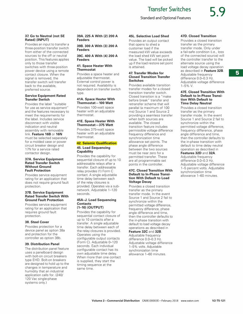
Volume 2—Commercial Distribution CA08100003E—February 2018 www.eaton.com V2-T5-121
5
5
5
5
5
5
5
5
5
5
5
5
5
5
5
5
5
5
5
5
5
5
5
5
5
5
5
5
5
5
5.9Transfer Switches
Standard and Optional Features
37. Go to Neutral (not SE Rated) (INPUT)Provides an input to transfer a three-position transfer switch from either of the connected sources to the off or neutral position. This features applies only to those transfer switches with three-position power device using a remote contact closure. When the signal is removed, the transfer switch will transfer back to the available, preferred source.
Service Equipment Rated Transfer SwitchProvides the label “suitable for use as service equipment”and the features necessary to meet the requirements for the label. Includes service disconnect with visible indication and neutral assembly with removable link. Feature 16B or 16Nmust be selected separately for a molded case or power circuit breaker design and 17N for a service rated contactor design.
37A. Service Equipment Rated Transfer Switch Without Ground Fault ProtectionProvides service equipment rating for an application that does not require ground fault protection.
37B. Service Equipment Rated Transfer Switch With Ground Fault ProtectionProvides service equipment rating for an application that requires ground fault protection.
38. Steel CoverProvides protection for a device panel as option 38a and protection for the controller as option 38b.
39. Distribution PanelThe distribution panel feature uses a panelboard design with bolt-on circuit breakers type EHD. Bolt-on breakers are designed to hold up to the changes in temperature and humidity that an industrial application calls for. (240/120 Vac single-phase systems only.)
39A. 225 A With (2) 200 A Feeders
39B. 300 A With (3) 200 A Feeders
39C. 400 A With (4) 200 A Feeders
41. Space Heater With ThermostatProvides a space heater and adjustable thermostat. External control power is not required. Availability is dependent on transfer switch type.
41A. Space Heater With Thermostat—100 WattProvides 100-watt space heater with an adjustable thermostat.
41E. Space Heater With Thermostat—375 WattProvides 375-watt space heater with an adjustable thermostat.
42. Seismic Qualification45. Load Sequencing CapabilityProvides the capability for sequential closure of up to 10 addressable relays after a transfer. Each addressable relay provides (1) Form C contact. A single adjustable time delay between each of the relay closures is provided. Operates via a sub-network. Adjustable 1–120 seconds.
45A–J. Load Sequencing Contacts (1–10) (OUTPUT)Provides the capability for sequential contact closure of up to 10 contacts after a transfer. A single adjustable time delay between each of the relay closures is provided. Operates using the configurable output contacts (Form C). Adjustable 0–120 seconds. Each individual configurable contact has its own adjustable time delay. When more than one contact is supplied, they start the timing sequence at the same time.
45L. Selective Load Shed Provides an output contact that opens to shed a customer load if the measured kW value exceeds the load shed kW set point value. The load will be picked up if the load restore set point is attained.
47. Transfer Modes for Closed Transition Transfer SwitchesProvides available transition transfer modes for a closed transition transfer switch. Closed transition is a “make before break” transfer and retransfer scheme that will parallel (a maximum of 100 ms) Source 1 and Source 2providing a seamless transfer when both sources are available. The closed transition feature includes permissible voltage difference frequency difference and synchronization time allowance set points. The phase angle difference between the two sources must be near zero for a permitted transfer. These are all programmable set points in the controller.
47C. Closed Transition With Default to In-Phase Transi-tion With Default to Load Voltage DecayProvides a closed transition transfer as the primary transfer mode. In the event Source 1 and Source 2 fail to synchronize within the permitted voltage difference, frequency difference, phase angle difference and time, then the controller defaults to the in-phase transition with default to load voltage decay operations as described in Feature 32C and 32B. Adjustable frequency difference 0.0–0.3 Hz. Adjustable voltage difference 1–5% volts. Adjustable synchronization time allowance 1–60 minutes.
47D. Closed TransitionProvides a closed transition transfer as the primary transfer mode. Only under a fail-safe condition (i.e., loss of the connected source) will the controller transfer to the alternate source using the load voltage decay operation as described in Feature 32B. Adjustable frequency difference 0.0–0.3 Hz. Adjustable voltage difference 1–5% V.
47E. Closed Transition With Default to In-Phase Transi-tion With Default toTime Delay NeutralProvides a closed transition transfer as the primary transfer mode. In the event Source 1 and Source 2 fail to synchronize within the permitted voltage difference, frequency difference, phase angle difference and time, then the controller defaults to the in-phase transition with default to time delay neutral operation as described in Features 32D and 32A. Adjustable frequency difference 0.0–0.3 Hz. Adjustable voltage difference 1–5 percent volts. Adjustable synchronization time allowance 1–60 minutes.
42. Seismic Qualification

V2-T5-122 Volume 2—Commercial Distribution CA08100003E—February 2018 www.eaton.com
5
5
5
5
5
5
5
5
5
5
5
5
5
5
5
5
5
5
5
5
5
5
5
5
5
5
5
5
5
5
5.9 Transfer Switches
Standard and Optional Features
47F. Closed/Load Voltage DecayControllers equipped with Feature Set 47F will perform a closed transition when both sources are synchronized in frequency, phase and voltage. Failure to synchronize will result in an open transition Time Delay Load Voltage Decay transfer. Time Delay Load Voltage Decay uses the load voltage measurements to sense back EMF that is generated when the transfer switch is in the Neutral position.
It provides a delay in transfer in either direction if an unacceptable level is sensed as established by a customer programmed level. The transfer will not take place until the back EMF decays below the acceptable programmed level. This feature has a separate setting of enabling or disabling the operation. If disabled, the transfer switch will not delay in the Neutral position and will transfer between the sources as fast as possible. This feature is not available with the Time Delay Neutral Optional Feature 32A.
47G. Closed/Time Delay NeutralControllers equipped with Feature Set 47F will perform a closed transition transfer when both sources are synchronized in frequency, phase and voltage. Failure to synchronize will result in an open transition Time Delay Neutral transfer. Time Delay Neutral provides a time delay in the transfer switch neutral position when both sources are open. This delay takes place when the load is transferred in either direction to prevent excessive in-rush currents due to out-of-phase switching of large motor loads.
47H. Parallel Limit TimerProvides an independent timing relay with NO contact (watchdog timer) activated only during a closed transition transfer. The timing is set to 100 ms per code requirements and will initiate a contact closure that can be used by the end user to annunciate an alarm or to trip an upstream breaker.
48. Communication ModulesProvides communications modules for the transfer switch controllers.
48D. EthernetCommunication (PXG900 Gateway)Translates Modbus RTU, QCPort or INCOM to Modbus TCP. The PXG900 Gateway includes embedded Web server monitoring of up to 64 connected devices.
48F. ModbusCommunication (MPONI)Provides Modbus RTU protocol via communications module.
48G. Modbus TCP/IPProvides a third-party device for Modbus 485 to Modbus TCP/IP pass through.
48M1–48M4. I/O ModuleEach I/O module provides four additional user configurable inputs and outputs. Up to four additional I/O modules can be added, either by the factory or in the field.
48MRAC. Multi-view Remote Annunciator with ControlProvides remote monitoring of source availability, source position and test status for up to eight transfer switches with the ATC-300+ or ATC-900 controller. Operates using Modbus protocol.
48P. Remote Annunciator Power SupplyProvides a remote mounted power supply providing DC power to the remote annunciator.
48RAC. Remote Annunciator with ControlProvides remote monitoring and control via a color touch screen display for the controllers. Operates using Modbus protocol (MPONI required for the ATC-600/800).
48U. USB Port for Memory StickProvides a device panel mounted USB port for uploading or downloading controller set points and for downloading event history.
49. Sensing Isolation TransformerProvides a set of control power transformers that converts the delta system sensing to a wye sensing input to the controller. The sensing isolation transformer is recommended for high resistance grounded systems and for grounded delta systems.
49A. Sensing Isolation TransformerOption 49A is available for Magnum ATSs.
49B. Sensing Isolation Transformer Option 49B is available for MCCB and contactor transfer switches.
49C. Multi-Tap Control Power TransformerThe multi-tap control power transformer is used to step-down voltage to 120 Vac for the transfer switch control circuit. Incoming voltage can be adjusted by moving the tap on the primary side from 208 V, 240 V or 480 V for 60 Hz applications or 220 V, 380 V, 415 V, 600 V for 50 Hz applications.
Option 51. Surge Protection DeviceTwo types of surge protection devices are used in Eaton automatic transfer switches. Both types meet the requirements for UL 1449 3rd Edition for surge suppression devices and are CE marked. The type CVX is used on Eaton wallmount ATS designs and the Eaton type SPD are used on floor-standing designs.
CVXThe CVX device features a Thermally Protected Metal Oxide Varistor technology and comes with high intensity LED phase status indicators.
SPDThe SPD features a Thermally Protected Metal Oxide Varistor technology. It comes with dual-colored protection status indicators for each phase and for neutral-ground protection mode. It comes with an audible alarm with silence button and a Form C contact.
An optional SPD with surge counter feature package is available. This provides six-digit surge counter with reset button.
51S1B. 50 kA—SPD standard source 1
51S2B. 80 kA—SPD standard source 1
51S3B. 100 kA—SPD standard source 1
51S4B. 120 kA—SPD standard source 1
51S5B. 160 kA—SPD standard source 1
51S6B. 200 kA—SPD standard source 1
51S7B. 250 kA—SPD standard source 1
51S8B. 300 kA—SPD standard source 1
51S9B. 400 kA—SPD standard source 1
51S1C. 50 kA—SPD standard with surge counter source 1
48. CommunicationModules
48F. ModbusCommunication (MPONI)
49C. Multi-Tap ControlpPower Transformer
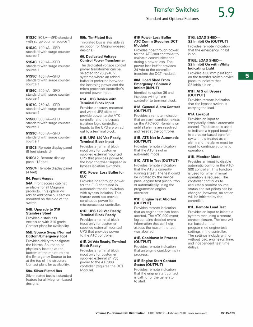
Volume 2—Commercial Distribution CA08100003E—February 2018 www.eaton.com V2-T5-123
5
5
5
5
5
5
5
5
5
5
5
5
5
5
5
5
5
5
5
5
5
5
5
5
5
5
5
5
5
5
5.9Transfer Switches
Standard and Optional Features
51S2C. 80 kA—SPD standard with surge counter source 1
51S3C. 100 kA—SPD standard with surge counter source 1
51S4C. 120 kA—SPD standard with surge counter source 1
51S5C. 160 kA—SPD standard with surge counter source 1
51S6C. 200 kA—SPD standard with surge counter source 1
51S7C. 250 kA—SPD standard with surge counter source 1
51S8C. 300 kA—SPD standard with surge counter source 1
51S9C. 400 kA—SPD standard with surge counter source 1
51SC8. Remote display panel (8 feet standard)
51SC12. Remote display panel (12 feet)
51SC4. Remote display panel (4 feet)
54. Front Access54A. Front access cabinet available for all Magnum products. This option will add an additional pull section mounted on the side of the switch.
54B. Upgrade to 316 Stainless SteelProvides a stainless enclosure with 316 grade. Contact plant for availability.
55B. Source Swap (Normal Bottom/Emergency Top)Provides ability to designate the Normal Source to be physically located at the bottom of the structure and the Emergency Source to be at the top of the structure. Contact plant for availability.
59a. Silver-Plated BusSilver-plated bus is a standard feature for all Magnum-based designs.
59b. Tin-Plated BusTin-plated bus is available as an option for Magnum-based designs.
60. Dedicated Voltage Control Power TransformerThe dedicated voltage control power transformer can be selected for 208/240 V systems where an added buffer is preferred between the incoming power and the micro-processor controller’s control power input.
61A. UPS Device with Terminal Block InputProvides a factory mounted and wired UPS sized to provide power to the ATC controller and the bypass isolation logic controller. Inputs to the UPS are wired out to a terminal block.
61B. UPS 120 Vac Ready, Terminal Block InputProvides a terminal block input only for customer supplied external mounted UPS that provides power to the logic controller supplied in bypass isolation switches.
61C. Power Loss Buffer for ELC Provides ride-through power for the ELC contained in automatic transfer switches with bypass isolation. This feature does not provide continuous power for microprocessor controller.
61D. UPS 120 Vac Ready, Terminal Block ReadyProvides a terminal block input only for customer supplied external mounted UPS that provides power to the ATC controller.
61E. 24 Vdc Ready, Terminal Block ReadyProvides a terminal block input only for customer supplied external 24 Vdc power to the ATC900 controller (requires the DCT Module).
61F. Power Loss Buffer ATC Comm (Requires DCT Module) Provides ride-through power for the ATC-900 controller to maintain communications during a power loss. The power loss buffer provides 24 Vdc to the controller (requires the DCT module).80A. Load Shed From Emergency / Source 2 Inhibit (INPUT)Identical to option 36 and includes wiring from controller to terminal block.
81A. General Alarm Contact (OUTPUT)Provides a remote indication that an alarm condition exists on the ATC-900. Remains on until all alarms are resolved and reset at the controller.
81B. ATS Not in Automatic (OUTPUT)Provides remote indication that the ATS is not in automatic mode.
81C. ATS in Test (OUTPUT)Provides remote indication that the ATS is currently running a test. The test could be initiated by the device panel engine test pushbutton or automatically using the programmed engine exerciser.
81D. Engine Test Aborted (OUTPUT)Provides remote indication that an engine test has been aborted. The ATC-900 event log contains detailed event information that can help assess the reason the test was aborted.
81E. Cooldown in Process (OUTPUT)Provides remote indication that an engine cooldown is in progress.
81F. Engine Start Contact Status (OUTPUT)Provides remote indication that the engine start contact is calling for the generator to start.
81G. LOAD SHED—S2 Inhibit On (OUTPUT)Provides remote indication that the emergency inhibit is on.
81GL. LOAD SHED—S2 Inhibit On with White Indicating LightProvides a 30 mm pilot light on the transfer switch device panel to indicate that S2 Inhibit is on.
81H. ATS on Bypass (OUTPUT)Provides remote indication that the bypass switch is carrying the load.
81J. LockoutProvides an input to temporarily disable automatic control. This feature is used to indicate a tripped breaker in a breaker-based transfer switch. It is treated as an alarm and the alarm must be reset to continue automatic operation.
81K. Monitor ModeProvides an input to disable automatic control in the ATC-900 controller. This function is used for when manual operation is required. The controller continues to accurately monitor source status and set points can be changed; however, no action will be initiated by the controller.
81L. Remote Load TestProvides an input to initiate a system test using a remote contact closure. The test will run based on the programmed engine test settings in the controller. The settings include with or without load, engine run time, and independent test time delays.
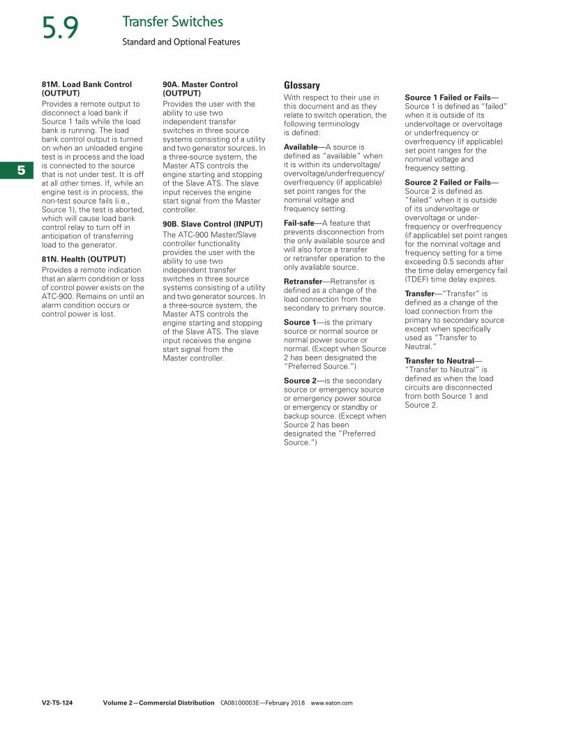
V2-T5-124 Volume 2—Commercial Distribution CA08100003E—February 2018 www.eaton.com
5
5
5
5
5
5
5
5
5
5
5
5
5
5
5
5
5
5
5
5
5
5
5
5
5
5
5
5
5
5
5.9 Transfer Switches
Standard and Optional Features
81M. Load Bank Control (OUTPUT)Provides a remote output to disconnect a load bank if Source 1 fails while the load bank is running. The load bank control output is turned on when an unloaded engine test is in process and the load is connected to the source that is not under test. It is off at all other times. If, while an engine test is in process, the non-test source fails (i.e., Source 1), the test is aborted, which will cause load bank control relay to turn off in anticipation of transferring load to the generator.
81N. Health (OUTPUT)Provides a remote indication that an alarm condition or loss of control power exists on the ATC-900. Remains on until an alarm condition occurs or control power is lost.
90A. Master Control (OUTPUT) Provides the user with the ability to use two independent transfer switches in three source systems consisting of a utility and two generator sources. In a three-source system, the Master ATS controls the engine starting and stopping of the Slave ATS. The slave input receives the engine start signal from the Master controller.
90B. Slave Control (INPUT)The ATC-900 Master/Slave controller functionality provides the user with the ability to use two independent transfer switches in three source systems consisting of a utility and two generator sources. In a three-source system, the Master ATS controls the engine starting and stopping of the Slave ATS. The slave input receives the engine start signal from the Master controller.
GlossaryWith respect to their use in this document and as they relate to switch operation, the following terminology is defined:
Available—A source is defined as “available” when it is within its undervoltage/overvoltage/underfrequency/overfrequency (if applicable) set point ranges for the nominal voltage and frequency setting.
Fail-safe—A feature that prevents disconnection from the only available source and will also force a transfer or retransfer operation to the only available source.
Retransfer—Retransfer is defined as a change of the load connection from the secondary to primary source.
Source 1—is the primary source or normal source or normal power source or normal. (Except when Source 2 has been designated the “Preferred Source.”)
Source 2—is the secondary source or emergency source or emergency power source or emergency or standby or backup source. (Except when Source 2 has been designated the “Preferred Source.”)
Source 1 Failed or Fails—Source 1 is defined as “failed” when it is outside of its undervoltage or overvoltage or underfrequency or overfrequency (if applicable) set point ranges for the nominal voltage and frequency setting.
Source 2 Failed or Fails—Source 2 is defined as “failed” when it is outside of its undervoltage or overvoltage or under-frequency or overfrequency (if applicable) set point ranges for the nominal voltage and frequency setting for a time exceeding 0.5 seconds after the time delay emergency fail (TDEF) time delay expires.
Transfer—“Transfer” is defined as a change of the load connection from the primary to secondary source except when specifically used as “Transfer to Neutral.”
Transfer to Neutral—“Transfer to Neutral” is defined as when the load circuits are disconnected from both Source 1 and Source 2.
Related Documents