Submittal Data Sheet: TempMaster® Omni™ Choice CV15 to CV28 Submittal data Job name: Location: Purchaser: Order number: Engineer: Submitted to: For: Ref: Approval: Construction: Submitted by: Date: Unit designation: Schedule number: Model number: Unit data Cooling performance Total capacity MBH Sensible capacity MBH Outdoor design temperature °F DB/WB Total supply air CFM Temp. of air entering evaporator coil °F Power input req. (less blower motor) kW Heating performance Electric heat kW Gas-fired input cap. MBH Supply air blower performance Total supply air CFM Ext. static press. IWG Blower speed RPM Power output req. BHP Motor rating HP Power input req. kW Electrical data Power supply Total unit ampacity amps Max. overcurrent device __ fuse __ breaker amps Total unit weight Weight including factory-installed options lbs 5783171-TSD-A-0819 Revision: A-0819 2019-08-01 Johnson Controls Ducted Systems

Welcome message from author
This document is posted to help you gain knowledge. Please leave a comment to let me know what you think about it! Share it to your friends and learn new things together.
Transcript

Submittal Data Sheet: TempMaster® Omni™Choice CV15 to CV28
Submittal data
Job name: Location:Purchaser: Order number:Engineer:Submitted to: For: Ref: Approval: Construction:Submitted by: Date:Unit designation: Schedule number: Model number:
Unit data
Cooling performance
Total capacity MBHSensible capacity MBHOutdoor design temperature °F DB/WBTotal supply air CFMTemp. of air entering evaporator coil °FPower input req. (less blower motor) kW
Heating performance
Electric heat kWGas-fired input cap. MBH
Supply air blower performance
Total supply air CFMExt. static press. IWGBlower speed RPMPower output req. BHPMotor rating HPPower input req. kW
Electrical data
Power supplyTotal unit ampacity ampsMax. overcurrent device__ fuse __ breaker amps
Total unit weight
Weight including factory-installed options lbs
5783171-TSD-A-0819 Revision: A-0819
2019-08-01
Johnson Controls Ducted Systems
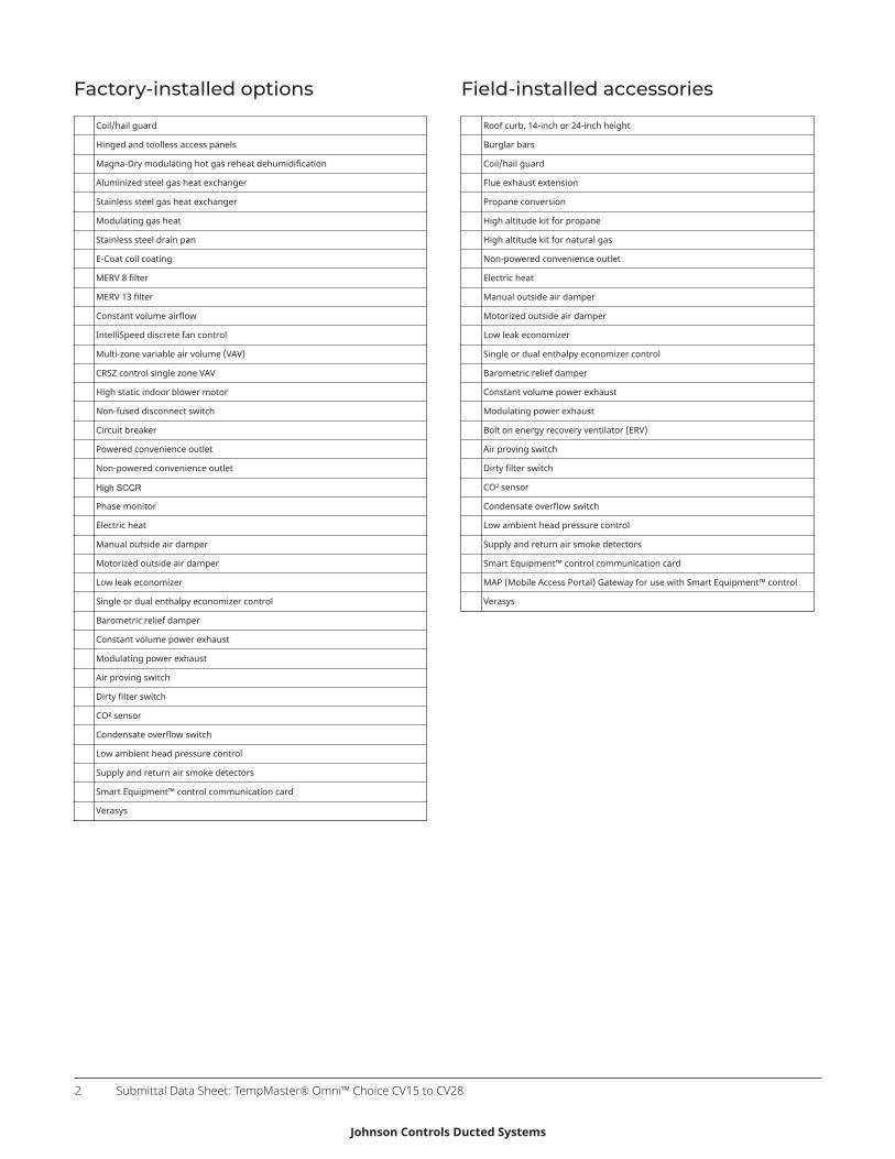
Factory-installed options
Coil/hail guard
Hinged and toolless access panels
Magna-Dry modulating hot gas reheat dehumidification
Aluminized steel gas heat exchanger
Stainless steel gas heat exchanger
Modulating gas heat
Stainless steel drain pan
E-Coat coil coating
MERV 8 filter
MERV 13 filter
Constant volume airflow
IntelliSpeed discrete fan control
Multi-zone variable air volume (VAV)
CRSZ control single zone VAV
High static indoor blower motor
Non-fused disconnect switch
Circuit breaker
Powered convenience outlet
Non-powered convenience outlet
High SCCR
Phase monitor
Electric heat
Manual outside air damper
Motorized outside air damper
Low leak economizer
Single or dual enthalpy economizer control
Barometric relief damper
Constant volume power exhaust
Modulating power exhaust
Air proving switch
Dirty filter switch
CO² sensor
Condensate overflow switch
Low ambient head pressure control
Supply and return air smoke detectors
Smart Equipment™ control communication card
Verasys
Field-installed accessories
Roof curb, 14-inch or 24-inch height
Burglar bars
Coil/hail guard
Flue exhaust extension
Propane conversion
High altitude kit for propane
High altitude kit for natural gas
Non-powered convenience outlet
Electric heat
Manual outside air damper
Motorized outside air damper
Low leak economizer
Single or dual enthalpy economizer control
Barometric relief damper
Constant volume power exhaust
Modulating power exhaust
Bolt on energy recovery ventilator (ERV)
Air proving switch
Dirty filter switch
CO² sensor
Condensate overflow switch
Low ambient head pressure control
Supply and return air smoke detectors
Smart Equipment™ control communication card
MAP (Mobile Access Portal) Gateway for use with Smart Equipment™ control
Verasys
Submittal Data Sheet: TempMaster® Omni™ Choice CV15 to CV282
Johnson Controls Ducted Systems

Physical dimensions
Figure 1: CV15 and CV18 physical dimensions
Submittal Data Sheet: TempMaster® Omni™ Choice CV15 to CV28 3
Johnson Controls Ducted Systems
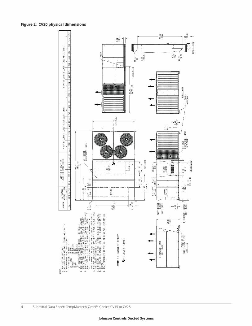
Figure 2: CV20 physical dimensions
Submittal Data Sheet: TempMaster® Omni™ Choice CV15 to CV284
Johnson Controls Ducted Systems
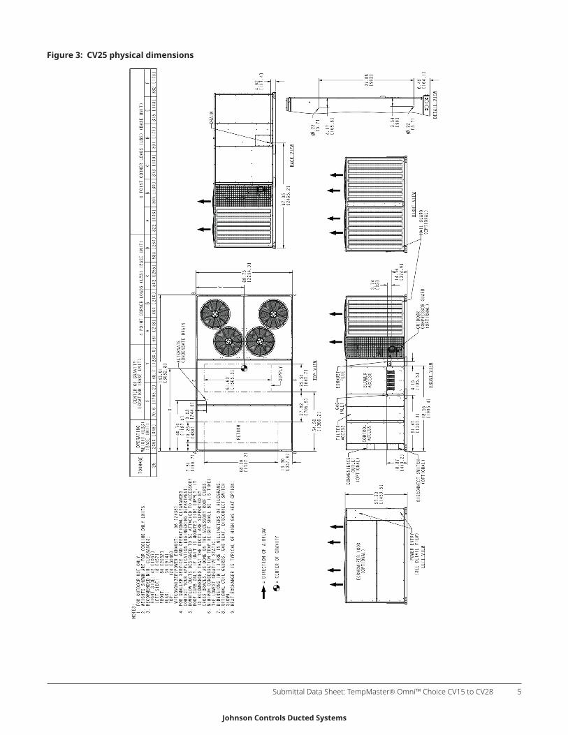
Figure 3: CV25 physical dimensions
Submittal Data Sheet: TempMaster® Omni™ Choice CV15 to CV28 5
Johnson Controls Ducted Systems

Figure 4: CV28 physical dimensions
Submittal Data Sheet: TempMaster® Omni™ Choice CV15 to CV286
Johnson Controls Ducted Systems

Rain hood dimensions
Figure 5: Rain hood dimensions
Table 1: Rain hood componentsItem DescriptionA Economizer, manual damper, and motorized damper rain hoodB Power exhaust rain hood
Utilities entryTable 2: Utilities entryEntry description Opening size diameter (in.)
Left Field drilled11 to maximum of 7/8 in.Control wiring
Bottom Field drilled1 to maximum of 7/8 in.Left Field drilled1 to maximum of 3 in.
Power wiringBottom Field drilled1 to maximum of 3 in.
Left2, 32, 3 2-in. hole with ¾-in. grommetGas piping
Bottom2 1-1/4 in. hole
Front44 1-1/2-in. holeCondensate drain
Bottom3, 4 2-in. hole with 1-1/4-in. grommet
1 Factory provided dimples show the hole location to facilitate the drilling of entry holes.2 3/4 in. NPT gas piping is required.3 You must insert the piping through the factory-installed grommet for a watertight seal.4 1 in. NPT female connection piping is required.
Note: You must field seal all entry holes to preventrain water entry into the building.
Submittal Data Sheet: TempMaster® Omni™ Choice CV15 to CV28 7
Johnson Controls Ducted Systems
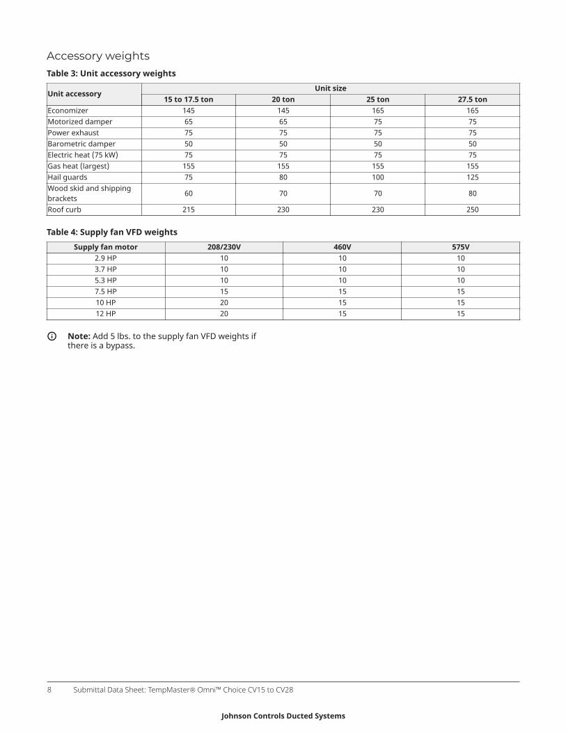
Accessory weightsTable 3: Unit accessory weights
Unit sizeUnit accessory
15 to 17.5 ton 20 ton 25 ton 27.5 tonEconomizer 145 145 165 165Motorized damper 65 65 75 75Power exhaust 75 75 75 75Barometric damper 50 50 50 50Electric heat (75 kW) 75 75 75 75Gas heat (largest) 155 155 155 155Hail guards 75 80 100 125Wood skid and shippingbrackets 60 70 70 80
Roof curb 215 230 230 250
Table 4: Supply fan VFD weightsSupply fan motor 208/230V 460V 575V
2.9 HP 10 10 103.7 HP 10 10 105.3 HP 10 10 107.5 HP 15 15 1510 HP 20 15 1512 HP 20 15 15
Note: Add 5 lbs. to the supply fan VFD weights ifthere is a bypass.
Submittal Data Sheet: TempMaster® Omni™ Choice CV15 to CV288
Johnson Controls Ducted Systems

Roof curbsThe following figures show the roof curbs for the units. All dimensions are in inches.
Return air
Supply air
Figure 6: 1RC0443 and 1RC0446 roof curb dimensions
Table 5: 1RC0443 and 1RC0446 dimensions
Roof curb X measurement (in.)1RC0443 141RC0446 24
The following units are compatible with 1RC0443 and 1RC0446 roof curbs.• CV15 • CV18
Submittal Data Sheet: TempMaster® Omni™ Choice CV15 to CV28 9
Johnson Controls Ducted Systems
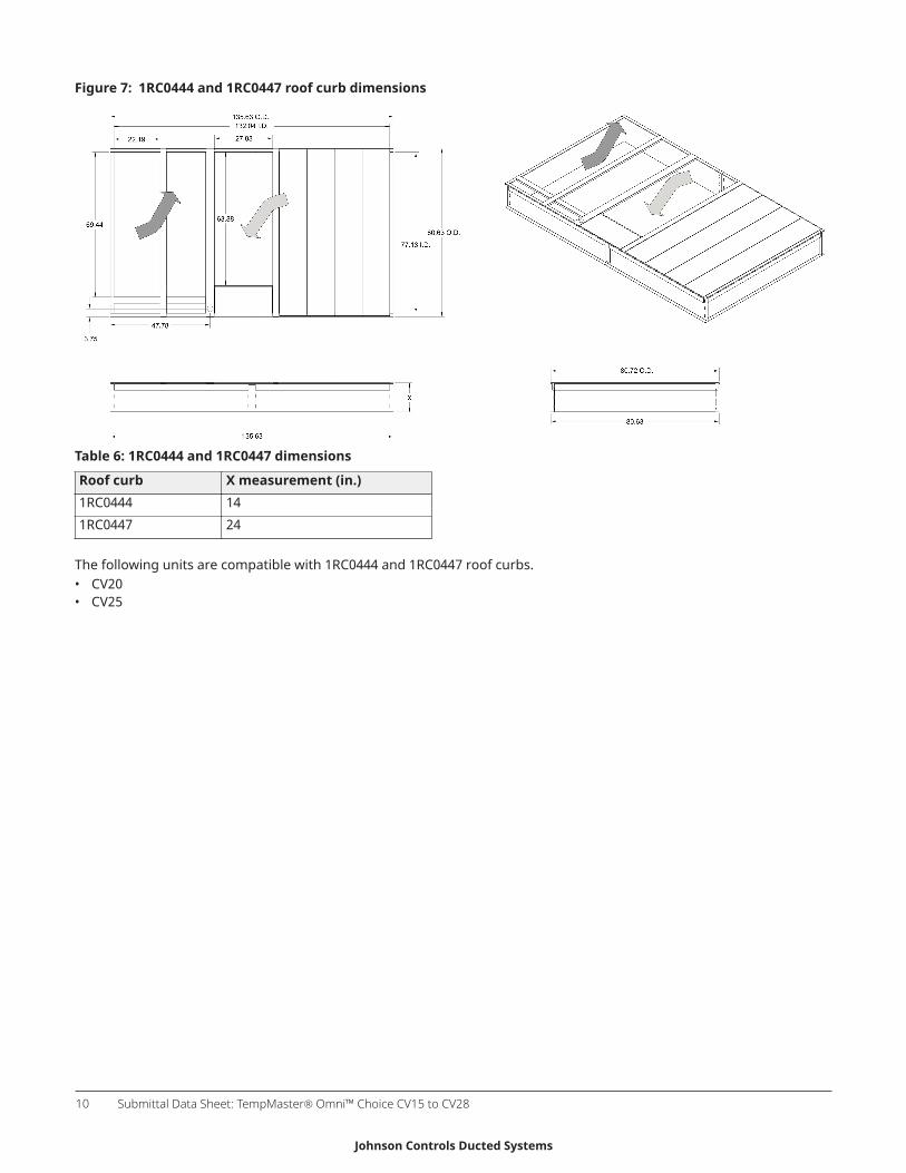
Figure 7: 1RC0444 and 1RC0447 roof curb dimensions
Table 6: 1RC0444 and 1RC0447 dimensions
Roof curb X measurement (in.)1RC0444 141RC0447 24
The following units are compatible with 1RC0444 and 1RC0447 roof curbs.• CV20• CV25
Submittal Data Sheet: TempMaster® Omni™ Choice CV15 to CV2810
Johnson Controls Ducted Systems
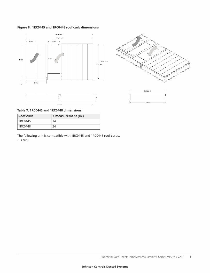
Figure 8: 1RC0445 and 1RC0448 roof curb dimensions
Table 7: 1RC0445 and 1RC0448 dimensions
Roof curb X measurement (in.)1RC0445 141RC0448 24
The following unit is compatible with 1RC0445 and 1RC0448 roof curbs.• CV28
Submittal Data Sheet: TempMaster® Omni™ Choice CV15 to CV28 11
Johnson Controls Ducted Systems

Figure 9: Roof curb cutaway
Table 8: Roof curb cutaway componentsItem Description Item DescriptionA Wood nailer D Roof felt (field supplied)B Curb frame E Rigid insulation (field supplied)C Counter flashing (field supplied) F Cant strip (field supplied)
Submittal Data Sheet: TempMaster® Omni™ Choice CV15 to CV2812
Johnson Controls Ducted Systems
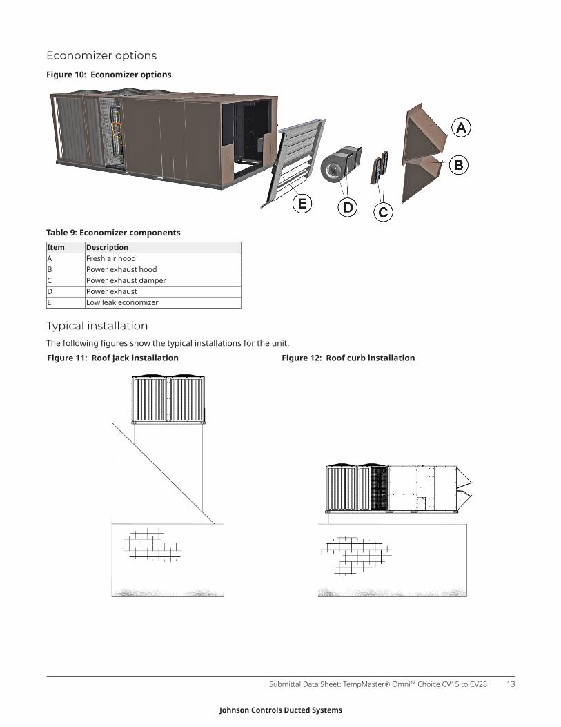
Economizer options
Figure 10: Economizer options
Table 9: Economizer componentsItem DescriptionA Fresh air hoodB Power exhaust hoodC Power exhaust damperD Power exhaustE Low leak economizer
Typical installationThe following figures show the typical installations for the unit.Figure 11: Roof jack installation Figure 12: Roof curb installation
Submittal Data Sheet: TempMaster® Omni™ Choice CV15 to CV28 13
Johnson Controls Ducted Systems

Subject to change without notice. Printed in U.S.A. Copyright © 2019 by Johnson Controls. All rights reserved.
Johnson Controls Ducted Systems
www.tempmasterhvac.com
Related Documents


