PHILADELPHIA ELECTRIC COMPANY 2301 MARKET STREET P.O. BOX 8699 PHILADELPHI A. PA.19101 SHIELDS L. D ALTROFF ELtcra c Pn c oN November 4, 1983 Docket Nos. 50-277 50-278 Mr. Darrell G. Eisenhut Division of Licensing U.S. Nuclear Regulatory Commission Washington, DC 20555 REFERENCES: 1. Generic Letter 83-28, " Required Actions Based on Generic Implications of Salem ATWS Events", July 8, 1983. 2. Letter, J. F. Stolz, USNRC to E. G. Bauer, Jr. , PECo, " Clarification of Required Actions Based on Generic Implications of Salem ATWS Events", October 21, 1983. Dear Mr. Eisenhut: Generic Letter 83-28, Required Actions Based on Generic Implications of Palem ATWS Events, issued July 8, requires licensees to address issues related to reactor trip system | reliability and general management capability in the areas of Post-Trip Review, Equipment Classification and Vendor Interface, Post Maintenance Testing and Reactor Trip System Reliability Improvements. The positions addressed in the Enclosure to Generic Letter 83-28 are as restated below along with our response for Peach Bottom Units 2 and 3. 8311090209 831104 PDR ADOCK 050002{ g| P l 'I \

Welcome message from author
This document is posted to help you gain knowledge. Please leave a comment to let me know what you think about it! Share it to your friends and learn new things together.
Transcript
PHILADELPHIA ELECTRIC COMPANY2301 MARKET STREET
P.O. BOX 8699
PHILADELPHI A. PA.19101
SHIELDS L. D ALTROFF
ELtcra c Pn c oN
November 4, 1983
Docket Nos. 50-27750-278
Mr. Darrell G. EisenhutDivision of LicensingU.S. Nuclear Regulatory CommissionWashington, DC 20555
REFERENCES: 1. Generic Letter 83-28, " Required ActionsBased on Generic Implications of SalemATWS Events", July 8, 1983.
2. Letter, J. F. Stolz, USNRC to E. G.Bauer, Jr. , PECo, " Clarification ofRequired Actions Based on GenericImplications of Salem ATWS Events",October 21, 1983.
Dear Mr. Eisenhut:
Generic Letter 83-28, Required Actions Based on GenericImplications of Palem ATWS Events, issued July 8, requireslicensees to address issues related to reactor trip system
| reliability and general management capability in the areas ofPost-Trip Review, Equipment Classification and Vendor Interface,Post Maintenance Testing and Reactor Trip System ReliabilityImprovements.
The positions addressed in the Enclosure to GenericLetter 83-28 are as restated below along with our response forPeach Bottom Units 2 and 3.
8311090209 831104PDR ADOCK 050002{
g|P
l 'I\
Mr. D. G. Eisenhut November 4, 1993Docket Nos. 50-277 Pace 2
50-279
1.1 POST-TRIP REVIEW (PROGRAM DESCRIPTION AND PROCEDURE)
Position
Licensees and applicants shall describe their nrogramfor ensuring that unscheduled reactor shutdowns areanalyzed and that a determination is made that the plantcan be restarted safely. A report describing theprogram for review and analysis of such unscheduledreactor shutdowns should include, as a minimum:
1. The criteria for determining the acceptability ofrestart.
2. The responsibilities and authorities of personnelwho will perform the review and analysis of theseevents.
3. The necessarv qualifications and training for theresponsible personnel.
4. The sources of plant information necessary toconduct the review and analysis. The sources ofinformation should include the measures andequipment that provide the necessary detail andtype of information to reconstruct the eventaccurately and in suf ficient detail for properunderstanding. (See Action 1.2.)
5 The methods and criteria for comparing the eventinformation with known or expected plant behavior(e.g., that safety-related equipment operates asrequired by the Technical Specifications or otherperformance specifications related to the safetyfunction).
6. The criteria for determining the need forindependent assessment of an event (e.o., a case inwhich the cause of the event cannot be nositivelvidentified, a competent group such as the PlantOperations Review Committee, will be consultedprior to authorizing restart) and guidelines on thepreservation of physical evidence (both hardwareand software) to suonort independent analysis ofthe event.
. - - . -. ._ _ ,
Mr. D. G. Eiscnhut November 4, 1993Docket Nos. 50-277 Page 3
50-279
RESPONSE
1.1.1 ACCEPTABILITY OF RESTART
Peach Bottom Procedure GP-1R, Scram Review Procedure,and GP-19 C.O.L. (Check-Off List for the Scram ReviewProcedure) were written and aporoved by the PlantOperations and Review Committee (PORC) on March 23,1993, as a result of the Salem ATWS events.
The latest revisions of these procedures, REV. 2 datedOctober 14, 1993 for GP-19 and REV. 3 dated September21, 1993 for GP-19 C.O.L., are attached as Exhibits 1and 2 respectively for your evaluation. Whencompleted, GP-19 C.O.L. forms the basis to determine theacceptability of niant restart. This check-off listrequires documentation of the event and key safetyparameters, use of the Sequence of Events Log and theDemand Log-Post Trip (Data Recall) Log, and a listing ofany discrenancies in Reactor System operations followingthe trip. The completed check-off list and theresultant Upset Report which is generated is thenreviewed in the nrocess as described in Resnonse to Item1.1.2. Approval to restart the reactor is granted inProcedure C.O.L. GP-?A, Reactor Startun Order (Exhibit3 ), by the Station Superintendent or alternate. C.O.L.GP-2A requires resolution of the Check-Of f List for theScram Review Procedure C.O.L. GP-19. Thus, approval forrestart cannot be granted unless there are nounexplained or unresolved conditions noted in C.O.L. GP-19 as a result of the trip.
1.1.2, RESPONSIRILITIES AND AUTHORITIES
The responsibilities for review and analysis following a
|niant tripping are delineated in Procedure GP-19, Scram
| Review Procedure (Exhibit 1). Following a planttripping, C.O.L. GP-19 is completed by Shif t Supervision'
or a Shif t Technical Advisor (STA) as directed by Shi f tSupervision. Using the completed C.O.L. and byconducting interviews with shift norsonnel involved, theSTA prepares a preliminary Upset Renort which is anarrative of the event and discusses the report withniant management face-to-face or by telephone prior toleaving the site at the end of his shift. The specificduties of the STA following a transient are delineated
|
. - , .___. - _ . ._ _ ,
Mr. D. G. Eisenhut November 4, 1993Docket Nos. 50-277 Page 4
50-278
in attached Procedure A-7, Apnendix 3, Shif t TechnicalAdvisor Duties and Reanonsibilities (Exhibit 4).
The Engineer-Operations or alternate reviews thecompleted C.O.L. GP-18 prior to restart to ensure thereare no unresolved or unexplained conditions an a resultof the event. The Engineer-Operations determines, byvirture of this review, if further review of the eventis required of the Plant Operations Review Committee(PORC) per the Scram Review Procedure. If the Enqineer-Operations determines that no further review isrequired, his signature on C.O.L. GP-19 completes thischeck-of f list for the ourpose of completing the ReactorStartup Order (Procedure C.O.L. GP-?A). As described inresnonse to Item 1.1.6 below, PORC and the NuclearReview Board may nrovide independent review as required.
1.1.3. OUALIFICATIONS AND TRAINING
The STA's at Peach Bottom all have a Bachelor's decreein a scientific or enqineering discipline with specifictraining in plant design, and resnonse and analysis ofthe plant for transients and accidents. Candidates forthe STA position mu9t undergo an intensive six-monthtraining program administered in the following areas:
Health Physics and Radiation Protection-
Chemistry Fundamentals and BWR Chemistry-
Materials Science and Reactor Materials-
- Atomic Physics and Reactor TheoryFluid Flow-
- Thermodynamics- Heat Transfer and BWR Heat Transfer- Management Skills- Simulator Training
Followinq the trainina nrocram, each STA candidate istested and evaluated for this position. The STA's mustsuccessfully connlete this traininq hefore beingassioned to a shift nosition. PORC is composed of thefollowina permanent members:
.-. . ._ - - . . _ . _ _ _ - . _
-. - _ _ _ _ - - _ . .
Mr. D. G. Eisenhut November 4, 1993Docket Nos. 50-277 Page 5
50-279
i A. Station Superintendent - ChairmanD. Station Assistant SuperintendentC. Engineer - TechnicalD. Engineer - MaintenanceE. Engineer - OperationsF. Engineer - ResultsG. Engineer - ReactorH. Engineer - Instrument & ControlI. Senior Health PhysicistJ. Shift Superintendent
i!
Each member of the PORC Committee meets or exceeds theminimum qualifications of ANSI N-18.1, 1971 forcomparable positions except the Senior Health Physicistwho meets or exceed the qualifications of RegulatoryGuide 1.9, September 1975. Individuals presentlyfilling the above positions A through C, E through H andJ nre Senior Licensed Onerators with up-to-daterequali fi cation. '
Members of the Nuclear Review Board, including theChairman and alternate members are appointed by theVice-President, Electric Production. These members havean academic degree in an engineering or physical sciencefield. Additionally, each member has a minimum of fiveyears technical experience, of which a minimum of threeyears is in one or more of the following areas:
A. Nuclear Power Plant OoerationsB. Nuclear EngineeringC. Chemistry and RadiochemistryD. MetalluroyE. Instrumentation and ControlF. Radiological SafetyG. Mechanical and Electrical EngineeringH. Quality Assurance Practices
;
.
w-w * -&- - - -* r,-- ,-<m-___,w._w--~+,s.-w vr a-4 W --1- v W - r e eiwt-tv*+ - eit'- - * = - - = - -M - - - - - -ti-~-=1w v--M-r ----
- _ _ _ ._ ... - -
Mr. D. G. Eisenhut Novenber 4, 1993Docket Nos. 50-277 Paqe 6
50-278,
|
1.1.4. SOURCES OF INFORMATION
To assist in transient analysis, the process computerprovides two programs which can help in reconstructingthe transient. These programs are:,
1. Sequence of Events Log, and2. Demand Log - Post Trip (Data Recall) Log
A backup process computer is used if nroblems with theprimary process comouter should occur. The primary andbackun orocess computers have the same capabilities.
SEQUENCE OF EVERPS LOG
The Sequence of Events Log logs the digital occurrencesduring the transient; e.g., trip signals, breakers openor closed. This log is broken down into two senarateparts, the NSSS points and the BOP points.
The computer / printer interface buffers have a capacity,of 80 NSSS state changes and 30 BOP state changes.Should either of these buffers fill, the scan of theassociated points ceases until that buffer is emptied.
! On this re-scan, the computer notes which secuence of| events points changed state from the last scan andi prints these points with the corresponding re-scan time,| not the actual change of state time.
This log is not demandable but is automaticallyinitiated from the operators or engineers console undercertain trip conditions.
DEMAND LOG - POST TRIP (DATA RECALL) LOG
The Post Trin Log trends un to 40 analog ooints once aminute _over a 40 minute period. At any given moment,the computer holds the nrevious 20 minute values inmemory. Once the Post Trin Log is initiated, it retainsthe past 20 minutes of memorv in a special outnut table
- - .. - - , - . - - _ _ _ . _ _- - - - - - - . - - - . , _ _ - _ ._. ,-- ,- _ - . - - . . - , -..
Mr. D. G. Eiscnhut November 4, 1493Docket Nos. 50-277 Page 7
50-279
and continues to store the next 20 minutes of data. Atthe end of this 20 minute period, (20 minutes after PostTrip Log initiated), the 40 minutes of data will beprinted on the OD typer.
The Post Trip Log is initiated automatically followingdesignated plant trins or on demand from the operatorsconsole. Following a designated trip, it will print outapproximately 20 minutes later on the OD typer. ThePost Trip Log will be lost in the event the computerloses power before the Post Trip Log is nrinted.
1.1.5. METHODS AND CRITERIA FOR COMPARISON
The Scram Review Check-Of f List, Procedure C.O.L. GP-18,is divided into sections for review and analysis of theevent. Completion of the check-off list allowsverification of the proner operation of the ReactorProtection System (RPS), Primary Containment IsolationSystem (PCIS), Emergency Core Cooling Systems (ECCS),and the 4Kv and 13Kv electrical systems.
C.O.L. GP-19 is formatted in such a way that systemresponse associated with the event is comrared with theexpected system response for a specific transient. Thisis acconnlished in Parts II throuqh VII by a YES or NOcheck-off at the beginning of each of these sections,which based on the nature of the scram indicates whethersystem response to the condition was required. I f NOis checked off, no further analysis of the system inthat PART is required. If YES is checked off, theremainder of that PART of the check-off list must hecompleted as indicated to determine if the system hasoperated as desiqned for the transient condition.
1.1.6. CRITERIA FOR NEED FOR INDEPENDENT ASSESSMENT
PORC review of an event is mandated if any of thefollowing conditions existed in respect to the tripning:
A. Undetermined cause of the SCRAMB. Unexnlained or unidentified action or eventsC. Failure of ECCS to operate procerly
.
- - . - - . . -- . - . , - .-
-_ __, -
Mr. D. G. Eisenhut November 4, 1993Docket Nos. 50-277 Page 8
50-278
D. Failure of all control rods to fully insertE. Failure of RPS, PCIS or other systems subject
to LSSS to operate as requiredF. Any other significant event deemed necessarv
for PORC review by the Engineer-Operations
PORC review is conducted to determine the necessaryremedial actions which must be taken prior to unitrestart. The PORC also determines if the condition wassuch that a review of the event is required by theNuclear Review Board (NRB). Review Of the event by theNRB is mandated if any condition concerning the eventwas different from those evaluated in the SafetyAnalysis Report or if NRB review is requested by thePORC.
! 1.2 POST-TRIP REVIEW - DATA AND INFORMATION CAPARILITY
Position
Licensees and applicants shall have or have planned acapability to record, recall and display data andinformation to permit dia7 nosing the causes ofunscheduled reactor shutdowns prior to restart and forascertaining the oroner functioning of safety-relatedi
equipment.
Adequate data and information shall be provided tocorrectly diagnose the cause of unscheduled reactor-
shutdowns and the proner functioning of safety-relatedequipment during these events using systematic safetyassessment procedures (Action 1.1). The data andinformation shall be displayed in a forn that permitsease of assimilation and analysis by persons trained inthe use of systematic safety assessment procedures.
A report shall be prepared which describes and justifiesthe adequacy of equipment for diagnosing an unscheduledreactor shutdown.
_ - . . ~. ,~ _ . , _ . . _ . _ . , - . _ _ . _ - _ _ _ _ _ _ _ _ ._. . . _ . . _ _ . . _ .
Mr. D. G. Eisenhut November 4, 1983'
Docket Nos. 50-277 Page 950-278
RESPONSE
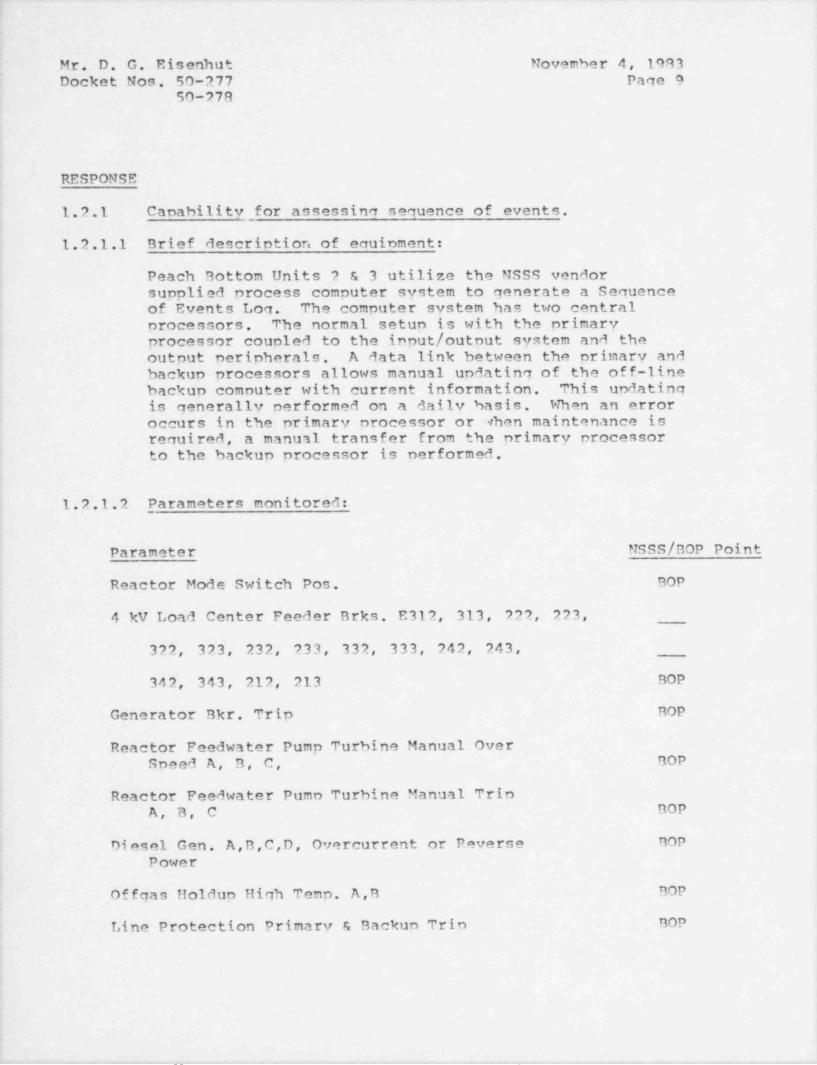
1.2.1 Canability for assessinq sequence of events.
1.2.1.1 Brief description of ecuinment:
Peach Bottom Units 2 & 3 utilize the NSSS vendorsupplied process computer system to generate a Sequenceof Events Log. The computer system has two centralprocessors. The normal setup is with the primaryprocessor coupled to the input / output system and theoutput peripherals. A data link between the primary andbackup processors allows manual updating of the off-linebackup comnuter with current information. This updatingis generally performed on a daily basis. When an erroroccurs in the primary processor or when maintenance isrequired, a manuti transfer from the primary processorto the backup processor is performed.
1.2.1.2 Parameters monitored:
Parameter NSSS/ BOP Point
Reactor Mode Switch Pos. BOP
4 kV Load Center Feeder Brks. E312, 313, 222, 223,
322, 323, 232, 233, 332, 333, 242, 243,
342, 343, 212, 213 BOP
Generator Bkr. Trip BOP
Reactor Feedwater Pump Turbine Manual Over'
Speed A, B, C, BOP
Reactor Feedwater Pumn Turbine Manual TripA, B, C BOP
Di esel Gen. A,B,C,D, Overcurrent or Reverse BOP
Power
Of fgas Holdun High Tenn. A,B BOP
Line Protection Primary & Backun Trip BOP
l
._ - - . _ _ . -. . . _ . - . - , _ . - - .- - __- - .
. _ __ _
Mr. D. G. Eisenhut November 4, 1083Docket Nos. 50-277 Pace 10
50-279
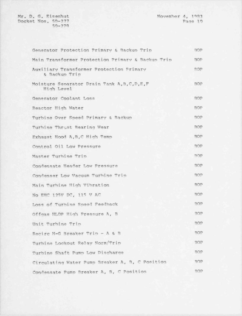
Generator Protection Primary & Backuo Trin BOP
Main Transformer Protection Primary & Backun Trio BOP
Auxiliary Transformer Protection Primary BOP& Backup Trip
Moisture Senarator Drain Tank A,B,C,D,E,F BOPHigh Level
Generator Coolant Loss BOP
Reactor High Water BOP
Turbine Over Speed Primary & Backup BOP
Turbine Thrust Bearing Wear BOP
Exhaust Hood A,B,C High Temp BOP
Control Oil Low Pressure BOP
Master Turbine Trio BOP
Condensate Header Low Pressure BOP
Condenser Low Vacuum Turbine Trip BOP
Main Turbine High Vibration BOP
No EHC 125V DC, 115 V AC BOP
Loss of Turbine Speed Feedback BOP
Offgas HLDP High Pressure A, B BOP
|Unit Turbine Trip BOP
Recirc M-G Breaker Trip - A & B BOP
Turbine Lockout Relay Norm / Trip BOP
Turbine Shaft Pump Low. Discharge BOP
Circulating Water Pump Breaker A, B, C Position BOP
Condensate Pumo Breaker A, B, C Position BOP
i
. _ . . _ , - - - . - , _ _ .. . _ - . . _ _ - - . . . _ . - - . - . - _. . _ . - - - _ . . . _ . - _ . - . . . , - . . _ _ . - . , _ . . , - -
- ._ .. - -- . _ ~
Mr. D. G. Eisenhut November 4, 1983Docket Nos. 50-277 Page 11
50-278i
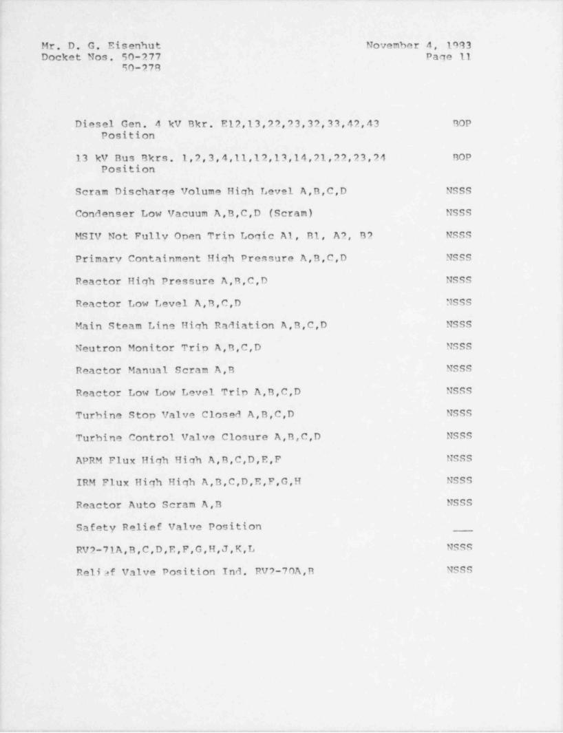
: Diesel Gen. 4 kV Bkr. E12,13,22,23,32,33,42,43 BOP
Position
13 kV Bus Bkrs. 1,2,3,4,11,12,13,14,21,22,23,24 BOPPosition|
Scram Discharge Volume High Level A,B,C,D NSSS|
Condenser Low Vacuum A,B,C,D (Scram) NSSS
MSIV Not Fully Open Trip Logic A1, B1, A2, B2 NSSS
| Primary Containment High Pressure A,B,C,D NSSS
Reactor High Pressure A,B,C,D NSSS
Reactor Low Level A,B,C,D NSSS,
Main Steam Line High Radiation A,B,C,D NSSS
Neutron Monitor Trip A,B,C,D NSSS
Reactor Manual Scram A,B NSSS
i
Reactor Low Low Level Trip A,B,C,D NSSS
Turbine Stop Valve Closed A,B,C,D NSSS
Turbine Control Valve Closure A,B,C,D NSSS
APRM Flux High High A,B,C,D,E,F NSSS *
IRM Flux High High A,B,C,D,E,F,G,H NSSS,
Reactor Auto Scram A,B NSSS
Safety Relief Valve Position
RV2-71A,B,C,D,E,F,G,H,J,K,L NSSSi
Reliaf Valve Position Ind. RV2-70A,B NSSS
!
. _ . - , - , - _ , - - ~ - - _ _ . . - _ _ - - - , . _ . _ , , . , _ , , _ - - , _ _ _ , _ _ . . _ . . _ . , . . , - , - . - . - . . - _ . . . . . -
.
Mr. D. G. Eisenhut November 4, 1993Docket Nos. 50-277 Page 12
-
50-279
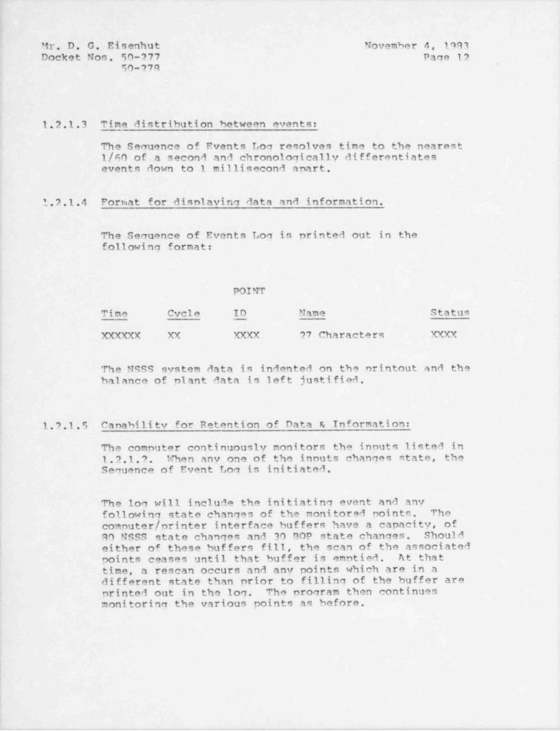
1.2.1.3 Time distribution between events:
The Sequence of Events Log resolves time to the nearest1/60 of a second and chronologically differentiatesevents down to 1 millisecond anart.
1.2.1.4 Forniat for disniaving data and information.
The Sequence of Events Log is printed out in thefollowing format:
POINT
Time Cycle ID Name Status
XXXXXX XX XXXX 27 Characters XXXX
The NSSS system data is indented on the nrintout and thebalance of plant data is left justified.
1.2.1.5 Canability for Retention of Data & Information:
The computer continuously monitors the innuts listed in1.2.1.2. When any one of the innuts changes state, theSequence of Event Log is initiated.
The log will include the initiating event and anyfollowing state changes of the monitored noints. Thecomputer / printer interface buffers have a capacity, of
i 90 NSSS state changes and 30 BOP state changes. ShouldI either of these buffers fill, the scan of the associated
points ceases until that buffer is emptied. At thattime, a rescan occurs and any points which are in adifferent state than prior to filling of the buffer areprinted out in the log. The program then continuesmonitoring the various points as before.
i
i
!
_ . . .
Mr. D. G. Eisenhut November 4, 1993Docket Nos. 50-277 Paqe 13
50-278
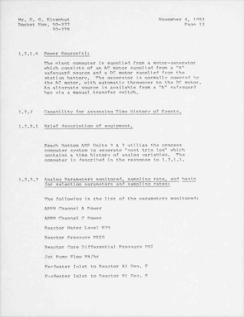
1.2.1.6 Power Source (s):
The plant computer is supplied from a motor-generatorwhich consints of an AC motor supplied from a "R"safeguard source and a DC motor sunplied from thestation battery. The generator is normally powered bythe AC motor, with automatic throwover to the DC notor.An alternate source is available f rom a "A" safeguardbus via a manual transfer switch.
1.2.2 Canability for assessina Time History of Events.
1.2.2.1 Brief descrintion of equinment.
Peach Bottom APS Units 2 & 3 utilize the processcomputer system to generate " post trin log" whichcontains a time history of analog variables. Thecomputer is described in the response to 1.2.1.1.
: 1.2.2.2 Analog Parameters monitored, samnling rate, and basisfor selection narameters and samnlino rates:
The following is the list of the narameters monitored:,
APRM Channel A Power
APRM Channel C Power
Reactor Water Level H2O
Reactor Pressure PSIG
Reactor Core Differential Pressure PSI:
Jet Pump Flow MS/hr
Feedwater Inlet to Reactor Al Dec. F
Freedwater Inlet to Reactor B1 Deg. F
f
-- , . - - - . - , - y __ - - - - . , . - . , - , - . - - - - , - , . , , - - . - , . - - . - - , , ,m , - , , - - . _ - - , - , - - % ,.,,-.----------v,- - - .
. _ _ , _ - . _ _ _ _ _ . . - . _ _ _ . - . . _- -. _ __
Mr. D. G. Eisenhut November 4, 1993Docket Nos. 50-277 Page 14
50-278.i
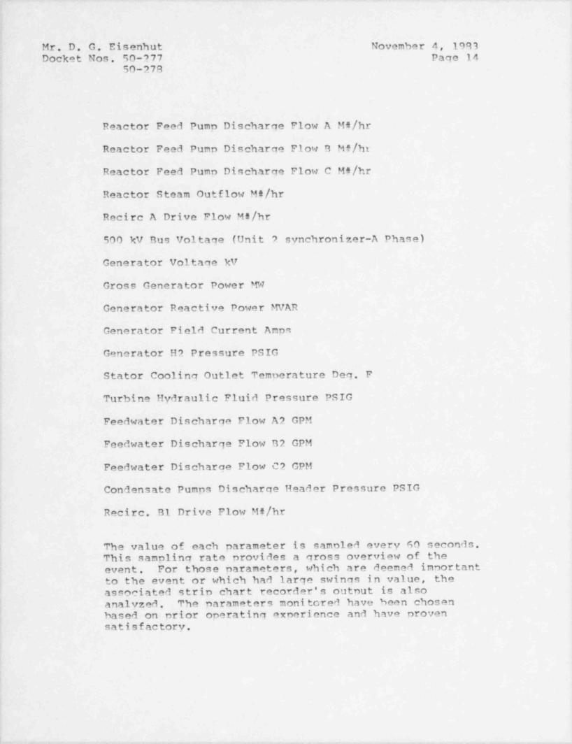
Reactor Feed Pump Discharge Flow A Mt/hr;
Reactor Feed Pump Discharge Flow B Mf/hr
Reactor Feed Pumn Discharge Flow C MS/hr
Reactor Steam Outflow MS/hr
Recirc A Drive Flow Mt/hr500 kV Bus voltage (Unit ? synchronizer-A Phase)
Generator Voltage kV
Gross Generator Power MW
Generator Reactive Power MVAR
Generator Field Current Amps.
|-
Generator H2 Pressure PSIG4
Stator Cooling Outlet Temnerature Deg. F
Turbine Hydraulic Fluid Pressure PSIG
Feedwater Discharge Flow A2 GPM
Feedwater Discharge Flow B2 GPM
Feedwater Discharge Flow C2 GPM
Condensate Pumps Discharge Header Pressure PSIG
' Recirc. B1 Drive Flow MA/hr
The value of each parameter is samnled every 60 seconds.|
This sampling rate provides a gross overview of the, event. For those parameters, which are deemed inportant
to the event or which had large swings in value, the'
associated strip chart recorder's outnut is also'
analyzed. The parameters monitored have been chosen;
based on nrior operating experience and have provensatisfactory.
{
- .- - - . - . - . . . . - _ . _ - . - . - - . - . - . . . . - - . - . - . - . .
. . - . - - .- . . _ _ _ . .. . .- _ - _ _ - _ - - . _ . _ . _ - . .- _ ..
j
j Mr. D. G. Eisenhut November 4, 1993: ' Docket Nos. 50-277 Page 15
,
; 50-27R!
'
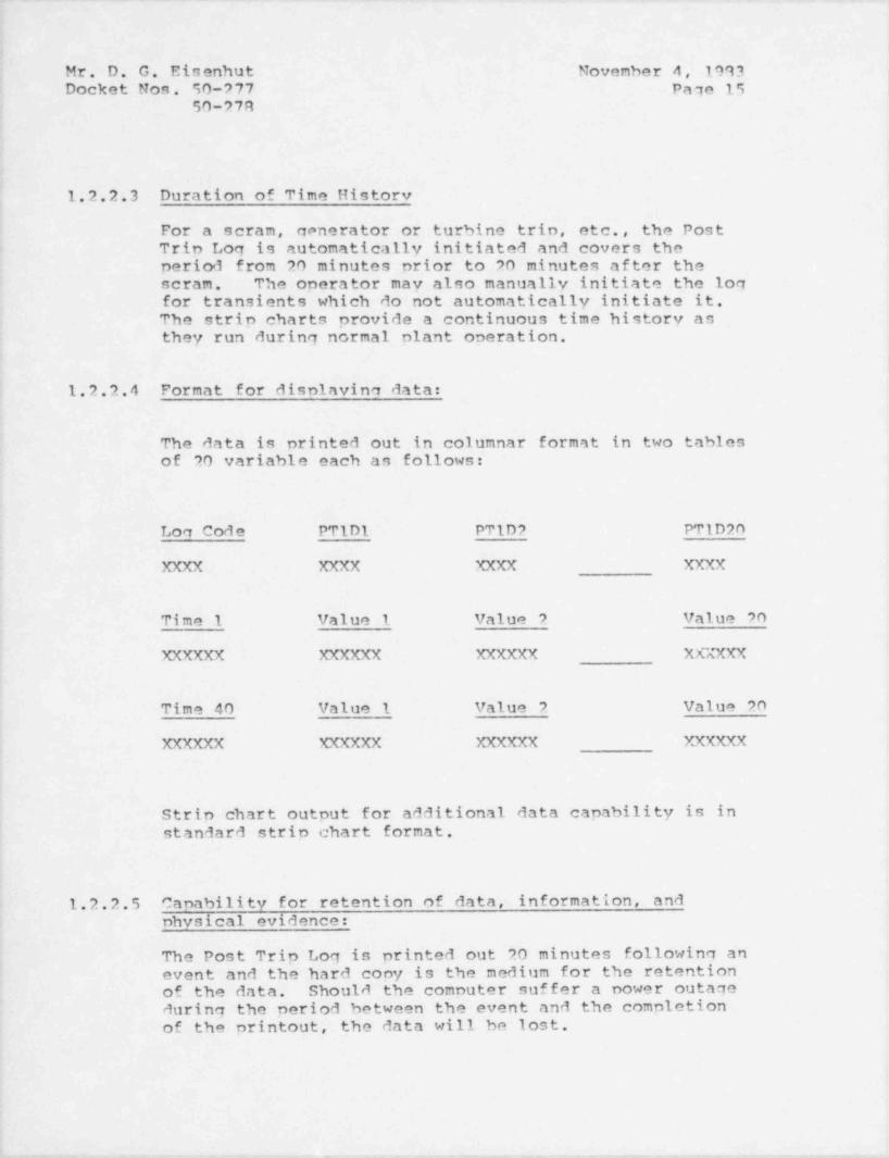
1.2.2.3 Duration of Time Historv:|
| For a scram, generator or turbine trip, etc., the PostTrip Log is automatically initiated and covers theperiod from 20' minutes prior to 20 minutes after thescram. The operator may also manually initiate the logfor transients which do not automatically initiate it.The strip charts provide a continuous time history asthey run during normal plant operation.
1.2.2.4 Format for disniavina data:
The data is printed out in columnar format in two tablesof 20 variable each as follows:
Loq Code PTlD1 PTlD2 PTlD20
XXXX XXXX XXXX XXXX4
Time 1 Value 1 Value 2 Value 704
XXXXXX XXXXXX XXXXXX XXXXXX
Time 40 Value 1 Value 2 Value 20
XXXXXX XXXXXX XXXXXX XXXXXX
Strip chart output for additional data capability is ini
standard strip chart format.i
1.2.2.5 Capability for retention of data, information, and4
1 physical evidence:
The Post Trip Log is printed out 20 minutes following anevent and the hard copy is the medium for the retention
.of the data. Should the computer suffer a power outaqo .
during the period between the event and the completion'
of the printout, the data will he lost.
'. - ~~ ~_ _ , _ _ - _ _ _ . _ _ , _ . _ . _ . _ . _ _ _ _ _ . . , _ _ _ . - , _ ~ - _ . _ _ _ _ .._., _ . .
_ _ . . _ _ _ _ _ _ . _
,
i
Mr. D. G. Eisenhut November 4, 1993 |IDocket Nos. 50-277 Page 16
50-278
'
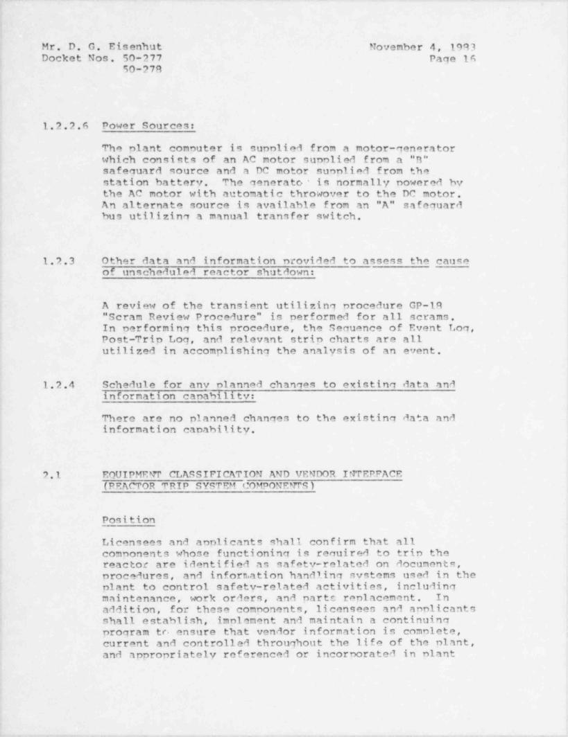
1.2.2.6 Power Sources:
The plant computer is supplied from a motor-generatorwhich consists of an AC motor sunplied from a "B"safeauard source and a DC motor suoplied from thestation battery. The generato/ is normally powered bythe AC motor with automatic throwover to the DC motor.An alternate source is available f rom an "A" safeguardbus utilizinq a manual transfer switch.
1.2.3 Other data and information nrovided to assess the causeof unscheduled reactor shutdown:
A review of the transient utilizing procedure GP-lR" Scram Review Procedure" is performed for all scrams.In performing this procedure, the Sequence of Event Log,Post-Trip Log, and relevant strip charts are allutilized in accomplishing the analysis of an event.
1.2.4 Schedule for any olanned channes to existinq data andinformation canabilitv:
There are no planned changes to the existinq data andinformation capability.
2.1 EQUIPMENT CLASSIFICATION AND VENDOR INTERFACE(REACTOR TRIP SYSTEM COMPONENTS )
Position
Licensees and applicants shall confirm that allcomponents whose functioning is required to trin thereactor are identified as safety-related on documents,procedures, and inforn.ation handling systems used in theplant to control safety-related activities, includingmaintenance, work orders, and parts replacement. Inaddition, for these components, licensees and apnlicantsshall establish, implement and maintain a continuingprogram to ensure that vendor information is comolete, ,
current and controlled throughout the life of the plant,and appropriately referenced or incorporated in plant
.
t' - - - '- - - - e- v w-T e- 'v' rwe-- -Nr=- v- - , , y y + MwW ---wMa= y -e wm W ww *s-ewt-s---zi-evt---6- ----er-+ * 5M*---+-+ ++---Jmp vrY
.- ._ . _ _ _ . . __ _ . _ .
Mr. D. G. EisQnhut November 4, 1993Docket Nos. 50-277 Page 17
50-778
instructions and procedures. Vendors of thesecomnonents should be contacted and an interfaceestablished. Where vendors cannot be identified, havegone out of business, or will not supply theinformation, the licensee or anplicant shall assure thatsuf ficient attention is paid to equipment maintenance,replacement, and renair, to compensate for the lack ofi
! vendor backup, to assure reactor trip systemreliability. The vendor interface program shall includeperiodic communication with vendors to assure that allapplicable information has been received. The nrogramshould use a system of positive feedback with vendorsfor mailings containing technical information. Thiscould be accomplished by licensee acknowledgement forreceipt of technical mailings. The program shall alsodefine the interface and division of responsibilitiesamong the licensees and the nuclear and non-nucleardivisions of their vendors that provide service onreactor trin system comoonents to assure that requisitecontrol of and applicable instructions for maintenance'
work are provided.
RESPONSE
Philadelphia Electric Company has reviewed the O-list inregard to the Salem ATWS events. The existino PeachBottom 0-list is comprised of safety-related itemseither by entire system or by functional components.
For exanole, the Neutron Monitoring System, a portion ofwhich contributes to the reactor trip function, islisted as a totally 0-system.
However, it is recognized that only portions of theneutron monitoring system have a safety relatedfunction. When activities are to be conducted on theneutron monitoring system, a determination is made ofthe O-status of the narticular portion of the system.
Other items which contribute to the reactor triofunction, such as nressure switches and transmitters,are identified as specific components in the O-list.
-- . ,_. -. . - - -.--. - . _ . _- . _ _ . - , - - - - _ - , _ - - . . . . _ _ ,
Mr. D. G. Eisenhut November 4, 1993Docket Nos. 50-277 Page 19
50-27R
Raned on this disparity of component classification,Philadelphia Electric Comnany is evaluating plans toenhance the Peach Bottom Q-list format by expanding theO-list for all Q-systems. It is exnected thatdevelopment of this revised Q-list will begin in early1094.
Regarding Vendor Interface, Philadelphia ElectricCompany has participated in the General Electric ServiceInformation Letter (SIL) system since its inception.Philadelphia Electric Company believes that the SILsystem provides the necessary instructions toincorporate vendor recommendations into applicableprocedures to constitute the vendor interface progran.To enhance our review of these types of documents, theIndependent Safety Engineering Groun (ISEG), which willbe formed by March of 1994, will review and disnositionthese vendor recommendations to insure that suchrecommendations are evaluated for their applicability toPeach Bottom. It is expected that this program will beeffective by June 1, 1994. Currently, the OperatingExperience Assessment Committee (OEAC) has beenreviewing selected SIL's screened by the Chairman of thecommittee and members of the OEAC. These SIL's arereviewed at monthly meetings of the committee whichconsists of representatives from Mechanical EnqineeringDivision, Electrical Engineering Division, QualityAssurance Division, Licensing Section, Nuclear SafetySection, the Superintendent of the Nuclear TrainingSection and the Peach Bottom Operations Engineer.
By letter dated September 6, 1993 from J.W. Gallagher,Philadelphia Electric Company to D.G. Eisenhut, USNRC,we advised the NRC that we are participating in the BWROwners' Group generic evaluation regarding equipmentclassification and vendor interface for reactor tripsystem components. The Owners' Group effort andsubsequent response to the Commission will be completedby February 29, 19R4.
,
Philadelphia Electric Company will re-evaluate itsprograms stated above when the Owners Group effort iscomnleted and nrovide to the Commission by April 15,1994, the status of our program or any modifications tothe program as a result of the Owners Groun ef fort.
, - . _ . -
- .._ - _ _ . . - _ . _ - - _ _ _ _ _ _ . . _ _ _ _ _ _ _ _ _ _ _ . . _ _ . - -..
j . Mr. D. G. Eisenhut November 4, 1993, Docket Nos. 50-277 Page 10' 50-278
.
'
2.2 EQUIPME R CLASSIFICATION AND VENDOR INTERFACE(PROGRAMS FOR ALL SAFETY-RELATED COMPONENTS );
'
Position+
Licensees and applicants shall submit, for staff review,a description of their programs for safety-relatedequinment classification and vendor interface asdescribed below:
a
1. For equipment classification, licensees andapplicants shall describe their program for'
ensuring that all components of safetv-relatedsystems necessary for accomplishing recuired safetyfunctions are identified as safety-related ondocuments, procedures, and information handling
';systems used in the plant to control safety-relatedactivities, including maintenance, work orders and
,
replacement parts. This description shallinclude:
':
1. The criteria for identifying components assafety-related within systems currentlyclassified as safetv-related. This shall nothe internreted to recuire changes in safety'
! classification at the systems level.
.
7 A description of the information handlingi system used to identify safety-related
components (e.g., computerized equinment list)I
and the methods used for its development andvalidati on.
|| 3. A descrintion of the nrocess by which station
personnel use this information handling systemto determine that an activity is safety-
' related and what orocedures for maintenance,surveillance, narts replacement and otheractivities defined in the introduction to 10
|CFR 50, Appendix n, apply to safety-relatedcomponents.
;
i
>
-w - ---,y , ,--.-,y..m, e,---- --%- ee ,,yw-r.-,-vmi---.rm,%_w,v ,w. p, -, i-,--m W,i-+-m- ,,a-- -e-- --.-ww-vw--
Mr. D. G. Eisenhut November 4, 1993Docket Nos. 50-277 Page 20
50-278
4. A description of the Management controlsutilized to verify that the procedures forprenaration, validation and routineutilization of the information handling systemhave been followed.
5. A demonstration that appropriate designverification and qualification testing issnecified for procurement of safety-relatedcomponents. The specifications shall includequalification testing for expected safetyservice conditions and provide supnort for thelicensees' receipt of testing documentation tosupport the limits of life recommended hv thesupplier.
RESPONSE
2.2.1.1 CRITERIA FOR SAFETY RELATED EDUIPMENT
Within a system currently defined as safety related, thecomponents of that system shall be considered safetyrelated if they are required to assure the following:
1. Integrity of the reactor coolant pressure boundary.
2. Capability to achieve and maintain a safe shutdown.
3. Capability to prevent or mitigate the consequencesof an accident which could result in potential off-site exposures comparable to the guidelines of 10CFR Part 100.
These criteria are in accordance with the requirementsof 10 CFR Part 50, Anpendix B.
_ _ _ .__ _ _ _ _ _ _ _ _ _ _ _ . . , _ _ _ _
_ - - _ -. . . _ - _ _ _ _ . . _ _ - _ .
.Mr. D. G. Eisenhut November 4, 1993Docket Nos. 50-277 Page 21
50-778
2.2.1.2 INFORMATIO?T HANDLING SYSTEM
|For Peach Bottom, safety related components areidentified via the Peach Bottom Project Q-List. The O-List is the single controlling document which completelyidentifies those structures, systems and componentswhich are safety related. As stated in the previousparagraph (2.2.1.1), the criteria for identifying thesecomponents as safety related are in accordance with therequirements of 10 CFR Part 50, Appendix B. ,
1
A part of the O-List are Quality Assurance Diagrams(OAD's), which are Piping and Instrument Drawings of
,
systems with the safety related portions shown in boldface lines to indicate that that section is safety i
related.
The Peach Bottom Project O-List was originally generated-
I by the plant Architect / Engineer. Safety related,( components and systems are listed in three basic
disciplines:,
1. Civil / Architectural7. Electrical3. Mechanical and Control Systems
The 0-list was turned over to Philadelphia ElectricCompany from the Architect / Engineer and is under the>
control of the Mechanical Project Engineer (MPE) in the .
Engineering and Research Department.;
! Activities involved in controlling the O-list by the MPEare controlled by adherence to Engineering and ResearchDepartmental Procedure (ERDP 3.2). The MPE is
iresponsible for receiving and distributing amendmentrequests and distributing the revised 0-list. The MPE
,
also maintains the project 0-list Amendment Request Log*
and the Register for 0-list holders.
i
,
4
- - - - - ..-e- - ,- -,,.,,--e,- ,..-,---r -T-*=---~w~'-wv i+--'*-=ww--* *-w ~wer----www=w--'- '--rw*w*=** -'*--'w''-*' ---*-''-v---v=w- t ~w** - -
. _ _
Mr. D. G. Eisenhut November 4, 1993Docket Nos. 50-277 Page 22
50-278
Processing 0-List Amendment Requests
The initiator of a 0-List Amendment Request completesthe Project O-List Amendment Request. The initiator'ssunervisor reviews the Amendment Request, and, ifacceptable, signs and dates the request and sends therequest form to the Mechanical Project Enqineer. TheMechanical Project Engineer assigns a number to theAmendment Recuest and enters it in a log which shows thenumber, the responsible group, and the disposition ofthe Request. The Mechanical Project Engineerdistributes copies of the Amendment Request via DocumentControl Forms (DCF's) which require review by OualityAssurance and by those engineering groups havingresponsibility for equipment involved with orinterfacing with the Amendment Request. The DCFindicates the enqineering group to receive the originalof the amendment request and to have overallresponsibility for nrocessing the amendment request.Quality Assurance Section, and each interfacing groupreceiving a copy of the amendment recuest for review,reviews the request and documents the results of thereview thereon. Quality Assurance Section and reviewingengineering groups sign, date and return their DCF's,the completed review checklists, and any comments to theresnonsible group indicated on the DCF. The ResponsibleEngineer, unon receiving the signed-off DCF's andanpronriate review c'tecklists, determines the overallacceptability of the Amendment Recuest and as necessary,holds meetinas or discussions with the reviewers toresolve conflicting comments. Such neetings ordiscussions are documented by the Responsible Enaineerand the results reflected on the review checklists ofthe anpropriate orqanization. For items being deletedfrom the O-list, a Safety Evaluation (SE) must beprepared in aucordance with Engineering and ResearchDepartmental Procedure (ERDP 3.3). A copy of the SE isattached to the apnroved amendment request to documentthat the change will not involve an unreviewed safetvquestion. If the deletion resulted from a modification,the Safety Evaluation performed for the modification issufficient if the deletion of the particular item fromthe O-list is clearly addressed and determined to benon-safety related. The safety evaluation must becompleted and signed by all required parties before theAmendment Request is sent to the Section, Branch Head,Group Leader. If the amendment request is aporoved, the
, _ _ , _ . - _ _ _- __ __ _ _ _ ___ _ -. ._- . . _ ..
Mr. D. G. Eisenhut November 4, 1993Docket Nos. 50-277 Page 23
50-278
following action is taken: (1) The Responsible Enqineerinitials and dates the original copy of the O-listAmendment Request and sends it to his Section/ BranchHead or Group Leader. (2) The Section/ Branch Head orGroup Leader, after receiving the initiated AmendmentRequest from the responsible engineer reviews therequest for completeness and accuracy and, ifacceptable, signs and dates the request. (3) TheResponsible Engineer shall: (a) initiate changes, inaccordance with anpropriate ERDP's to each of thedocuments listed in the Amendment Request, except forQuality Assurance Diagrams and other drawings referencedin the Q-list which are revised in accordance with otherERDP's; (b) provides the approved 0-list AmendmentRequest and the completed review checklists and DCF's tothe Mechanical Project Engineer; and (c) initiateschanges to appropriate OAD's and other drawingsreferenced in the O-list in accordance with otherERDP's.
The Mechanical Project Enqineer or staff: (a) recordsapproval of the Q-list Amendment Request number in thelog; (b) sends the connleted review checklists, DCF'sand a copy of the signed Amendment Request to theDocument Administration Center (DAC); (c) distribute theO-list Amendment Request within 14 days after receivingit to all registered holders of the O-list via thetransmittal / receipt form and record the return ofreceipts in a log which lists each holder of acontrolled copy of the O-list, each 0-list Amendment,and 0-list Revision issued. (Receints may be discarded
,
after their return has been recorded in the loq.); and(d) enters the O-list Amendment Request Number in the'
Mechanical Engineering Division Outstanding Items Listto track its status.
All registered 0-list holders incornorate O-list;
Amendment Requests into the front of their copy of the| O-list and return their receipts to the Mechanical
Project Engineer. The MPE initiates periodic follow-upsto ensure that the holders of the 0-lists return thereceint forms.
|i
|
. . ._ .. _ _-- _ - - _ . _
Mr. D. G. Eisenhut November 4, 1993Docket Nos. 50-277 Page 24
50-278
Processing Revisions to the Project O-List
As a minimum, the Mechanical Project Engineer revisesand reissues the complete O-list when one of the
,
following occurs: (1) within three months after thefifth Q-list amendment has been issued against a givenrevision of the 0-list; and (2) within three monthsafter any 0-list amendment, which is issued against thecurrent revision of the O-list, attains an age of twoyears. Revised portions of the O-list are annotated inthe margin adjacent to the change (s) with a verticalbar, the 0-list revision number in a triangle, and the4
number of the 0-list amendment request which authorizedthe change directly below the triangle. No change tothe O-list is permitted unless the change has beenauthorized by an approved 0-list Amendment Request.
Revisions to the 0-list are prepared by the MechanicalProject Engineer or staff, signed by the Mechanical
| Project Engineer after ensuring that_the only changesare those authorized by the approved 0-list AmendmentRequest and then issued via the Transmittal ReceintForm. Revisions to the Project 0-list become effectiveon the date that the Mechanical Project Engineer signs
i the revision. The Mechanical Project Engineer recordsthe Fransmittal of the revision and return of receipts.
in the log. Holders of the Project 0-list maintaintheir copies of the 0-list current and returntransmittal receipts to the Mechanical Project Engineer.'
The MPE initiates periodic follow-ups to ensure that theholders of the O-list return the receipt forms.
i 2.2.1.2 USE OF INFORMATION HANDLING SYSTEM
i
Safety related activities performed on safety related
,
equipment are required by administrative maintenance! procedure to be conducted under the Maintenance Request
Form (MRF) System. Philadelphia Electric Comoany is;
! currently establishing a computer file on plantmaintenance activities. This file is called theComputerized History and Maintenance Planning System.
(CHAMPS). The CHAMPS system will automate the MRFSystem for planned and preventive maintenance activitiesin the plant..
,
D
.-...y-. .----~~---,ww.- ----.e-- -.r~.-- -,c-,,----,r----.--,-m.-,m,--,emt. - - -,- me---m --- - , - - - , - - . . . , m..~-,.r-,wr- ,-.-w-> ,m- .
Mr..D. G. Eisenhut Movember 4, 1983Docket Nos. 50-277 Page 25
50-278
i
The MRF requires (in Section 7 of the MRF) plant staffinvestigation and aporoval to perform the work. Section2 of the MRF, requires among other things, that the O-list status of the equipment be indicated. At thepresent time, this action is carried out by theanpropriate Plant Encineering Staff Supervisor byconducting a review of the hard copy of the latestrevision of the 0-list which is generated as describedin the response to Item 2.2.1.2.
The CHAMPS Program, when fully operational, will providean automated method for MRF preparation and trackinn.*
It is exnected that the system will be in operation inJuly 1994. Philadelphia Electric Comnany is considering'
the incorporation of the revised 0-list discussed inresponse to Item 2.1 into the CHAMP 3 program. If thisis completed, the CHAMPS program will automaticallyinsert the O-list status of the component into Section 2of the computerized MRF. We do not know at this timewhen this automation will be complete: however, theplant engineering staf f supervisor's review of theproject 0-list is adequate to ensure that safety relatedactivities are carried out according to proceduralcontrols for 0-listed items.
2.2.1.4 MANAGEMENT CONTROLS
Th' Mechanical Project Engineer is responsible forcoordinating, maintaining, and distributing requests forrevisions to the Project Summary 0-List. Control of 0-list activities by the Mechanical Project Engineer ismaintained by Engineering and Research DepartmentalProcedures. These procedures are anproved by
| Engineering and Research Denartment management and|
control all activities involving handling of the O-list.
Philadelphia Electric Company's Quality AssuranceProgram assures throuqh audits and surveillance thatprocedures for preparation and utilization of the O-Listed system have been followed.
The Engineering and Research Department QualityAssurance Section audits activities regarding the O-Listat least every two years to determine that the O-Listhas been maintained and utilized properly.
- - _ __ _ _ _ -__ ._._ -__- . _ _ . _ , _ _ _ _- ~ . _
.
I
l
Mr. D. G. Eisenhut November 4, 1983 ]Docket Nos._50-277 Page 26 !
50-270
The Electric Production Department Quality AssuranceDivision in turn audits the Engineering and ResearchQuality Assurance Section at least every two years toensure that the Engineering and Research QualityAssurance Section activities are properly conducted.Additionally, the Electric Production Department QualityAssurance Division routinely audits plant procedures andthe Maintenance Request Form System to insure that plantactivities regarding safety related equipment areproperly implemented.
7.2.1.5 PROCUREMENT OF SAFETY RELATED EQUIPMENT
Engineering and Research Department Procedures (ERDP's)assure that appropriate design verification andqualification testing for expected safety serviceconditions is specified for procurement of safetyrelated components. The ERDP's contain provisions whichensure that qualification documentation is received.The anplicable ERDP's are:
ERDP 3.4 " Procedure for Design Control".
This nrocedure requires that the design inputdocuments prepared for each modificationaddresses the environmental qualifications ofequipment and the process and serviceconditions expected.
The following three procedures require review of theprocurement documents to ensure that the purchasedequipment is designed to operate in the expected serviceand process conditions and qualified for the expectedenvironment. Supporting qualification documentation isrequired as a condition of payment on all purchase-orders.
ERDP 4.4 " Procedure for Procurement of SpeciallyEngineered Enuipment Materials, Services or>
Combination thereof with a Specification" .
_ _ . . _ _ _ _ _ _ _ _ _ , _ . . . i __ ______ - - _ _ _ . _._
Mr. D. G. Eisenhut November 4, 1993Docket Nos. 50-277 Page 27
50-279
ERDP 4.5 " Procedure for Procurement of Nuclear SafetyRelated Items and Services by the PreliminaryRequisition Method".
ERDP 4.6 " Procedure for Procurement of Nuclear SafetyRelated Items under the Catalog Method".
ERDP 6.3 " Procedure for Processing Documents", providesthe logging and control of the incoming vendordocuments which assure the incorporation ofthe required design parameters and assurescompany review of the equipment limited lifecomn,onents.
ERDP 6.2 Procedure for Processing VendorDocumentation".
The procedure provides for the logging andcontrol of the incoming vendor documents. Therequired review ensures the incornoration ofthe required design parameters and assuresidentification of the equipment with limitedlife conponents. The data concerning limitedlife components is then entered into acomnuter program utilized for maintainingequipment. The required maintenance for thesecomponents will then be " flagged" at theappropriate times.
ERDP 7.1 " Procedure for Receint, Inspection, andStorage of Materials and Equipment" .
;
This procedures provides a Oc hold on anyequipment which is missing documentation.This ensures that all procured equinment hashad the aporooriate review.
I
- - . - . . . .- .. - - . _ .. - . . . - - . - . . -
. - _- - . ~ . . - - - - - . - . - _ . _ - - - -.
Mr. D. G. Eisenhut November 4, 1983Docket Nos. 50-277 Page 24
50-278
Additionally, procurement of safety related equipment, procured by the Electric Production Department is| controlled by Administrative Procedure A-27 (Procedurej for Material Contrcl' System). This procedure specifies
the methods for control of parts replacement. Thisprocedure adresses: the references and terms forprocurement; the classification and safety relationship;the technical and quality assurance requirements;receipt inspection and general procurement guidance.
I
2.2 EQUIPMENT CLASSIFICATION AND VENDOR INTERFACE (Continued)(PROGRAMS FOR ALL SAFETY-RELATED COMPONENTS)
Position
2. For vendor interface, licensees and applicantsshall establish, implement and maintain acontinuing program to ensure that vendorinformation for safety-related components iscomplete, current and controlled throughout thelife of their plants, and appropriately referenced<
or incorporated in plant instructions andprocedures. Vendors of safety-related equipmentshould be contacted and an interface established.Where vendors cannot be identified, have gone outof business, or will not supply information, thelicensee or applicant shall assure that sufficientattention is paid to equipment maintenance,replacement, and repair, to compensate for the lackof vendor backup, to assure reliabilitycommensurate with its safety function (GDC01). The
f - program shall be closely counled with action 2.2.1above (equipment qualification). The procram shall
I include periodic communication with vendors toassure that all applicable information has beenreceived. The program should use a system ofpositive feedback with vendors for mailingscontaining technical information. This could beaccomplished by licensee acknowledgment for receiptof technical mailings. It shall also define theinterface and division of responsibilities amongtl.< licensee and the nuclear and non-nuclear
3
! divisions of their vendors that provide service onsafety-related equipment to assure that requisite,
,
- --_. _. . _ _ _ _ _ _ _ _ _ . _ _ _ _ _ _ _ _
. - _ _ - _ - - . _ - _ - _ - _ - . - - -_
Mr. D. G. Eisenhut November 4,'1993Docket Nos.-50-277 Page 29
50-278a
; control of and applicable instructions formaintenance work on safety-related equipment areprovided.
RESPONSE
Philadelphia Electric Comoany has been an activeparticinant in INPO NPRDS and SEE-IN Programs since
~ their inception. The Significant Operating ExperienceReports and Significant Event Reports issued by INPO arereviewed for applicability to Peach Bottom by the ;
; Nuclear Generation Division.'
The NRC has concurred with utilization of these INPOprograms as vendor interface by letter from D. G.Eisenhut USNRC to E. P. Grif fing,INPO-NUTAC Chairman,dated September 29, 1993 in regards to an INPO sponsored'
NUTAC effort.
By letter dated September 6, 1993 from J.W. Gallagher,Philadelphia Electric Company to D.G. Eisenhut, USNRC,we informed the NRC that we are participating in the'
INPO sponsored NUTAC for a generic evaluation of the NRCposition regarding equinment classification and vendorinterf ace for all other safety-related components. TheNPRD System may also be routinely used to provide vendorinformation on installed safety related equinment. The
,
NUTAC effort is expected to be comnleted by February 1,'
1994. After evaluation of the results of the NUTACeffort, we expect to submit our response to thisposition by April 15, 1994
,
J
l
i
- - ,- , _ - , , _ . . . . _ _ . _ , , _ - _ _ , , . - _ _ . _ _ _ - _ _ . . _ . _ , , , _ _ - ,,_ ,_.-. - , _ _ _ - _.. _... . .. _ .-
- . .. . . - . - _- -- _. .- = _- - _ . - . . . .-
;
!
Mr. D. G. Eisenhut November 4, 1993,
Docket Nos. 50-277 Page 3090-278,
;
,
k
3.1 POST-MAINTENANCE TESTING (REACTOR TRIP SYSTEM COMPONENTS)
i'Position
The following actions are anplicable to post-maintenance;
i testing:4
i
l. Licensees and applicants shall submit the results'
of their review of test and maintenance' proceduresand Technical Specifications to assure that post-maintenance onerability testing of safety-relatedcomponents in the reactor trip system is reauiredto be conducted and that the testing demonstratesthat the equinment is capable of performing itssafety functions before being returned to service.
2. Licensees and applicants shall submit the results,
of their check of vendor and engineering'
recommendations to ensure that any appropriate test.quidance is included in the test and maintenanceprocedures or the Technical Snecifications, whererequi red .
1
; 3. Licensees and applicants shall identify, ifapplicable, any post-maintenance test requirementsin existing Technical Specifications which can bedemonstrated to degrade rather than enhance safety.
.
Appropriate changes to these test requirements,| with supoorting justification, shall be submitted
for staff approval. (Note that action 4.5'
discusses on-line system functional testing.)
n.
RESPONSE
i 3.1.1. POST MAINTENANCE PROCEDURES:
Post maintenance operability testing is addressed in
[Section 2 of the Maintenance Request Form (MRF) which is
,
governed by plant administrative procedure A-26;
(Procedure for Corrective Maintenance) and A-26AI (Procedure for Corrective and Preventive Maintenance
. Using CHAMPS ) .,
|
!
!
- .~ - - , - _ _ _ _ . . . . _ . ~ _ . - . . . _ _ , . . _ . . _ . _ . . . . . _ _ , _ _ _ _ _ _ , _ . - , . . _ . _ _ _ . _ _ _ _ _ , _ _
.
Mr. D. G. Eisenhut Novenber 4, 1993Docket Nos. 50-277 Page 31
50-278
Since CHAMPS is in the developmental stage, somemaintenance activities are still performed using 'hard'copy MRF' s in which Procedure A-26 is in force. Forthose MRF's currently generated by the CHAMPS program,Procedure A-76A is the governing procedure. Howevercompletion of the MRF for post-maintenance testingprocedures are handled the same irresnective of whichprocedure is in force.
The MRF, as discussed in response to Item 2.2.1.3, is
completed prior to performance of the work by theaporoprinte Engineering Staff Supervisor. Both themethod to verify post-maintenance operability and theresponsible group are stated in this section forestablishing the post-maintenance operabilityrequirements. The Operation Verification Method sectionof the MRP specifies sufficient post maintenancetesting, observation requirements or acceptance criteriato assure that the equinment is returned to fullyoperable status.
If the scone of the work activity which is to beperformed is not as originally snecified, proceduresrequire that the work groun supervisor must inform theEngineering Staff Supervisor or Shif t Sunervision whowill in turn take annronriate action. This may includechanging the post reoair testing reouirements on the MRPif the original snecified testino requirements are notsufficient to meet the revised work scope.
When the specified work is completed, the groupspeci fi ed in Section 2 to perform the operationverification, reviews the oneration verification methodagainst the work completed to determine if the snecifiedtest method is appropriate. If changes are required tothe specified test method, the changes are initiated bythe supervisor of the responsible group.
The proper nost maintenance operability testing is thusensured by following procedure A-26A.
3.1.2 VENDOR AND ENGINEERING RECOMMENDATIONS
Following the Salem ATWS events and prior to receipt ofGeneric Letter 83-28, Philadelnhia Electric Comnanybegan a nrocram to determine which Peach Bottom vendor
- - -- . _ . _ -
- - . - -__ . -. - . . - -- - - -
i
Mr. D. G. Eisenhut November 4, 1993;
Docket Nos. 50-277 Page 3250-278'
.
i manuals should be updated to incorporate the latest
;
vendor information available and changes resulting fromplant modifications that have been made since receipt of!
the vendor manuals. Various lists of vendor manuals
| have been generated to determine if all manuals arecontained within a central permanent and controlledfile. Thirty-five of these many hundreds of vendormanuals have been identified as manuals with the highestpriority for updating. One of these manuals has been .
updated. A program for updating other manuals is being.,
| develoned. This program will not be finalized untilinput from the Owners Group effort is available '
1
! (discussed in response to Item 2.1). -Incorporation ofall current vendor information into Peach Bottomprocedures at this time cannot be done until it has beendetermined that the vendor manuals contain the latest
i vendor information.
Vendor manuals and procedures for reactor trip functioncomponents will be addressed following the results ofthe Generic Owners Groun effort. Philadelphia ElectricCompany will submit a description of our proposedprogram following completion of the Owners Group effortby April 15, 1994.*
3.1.3 TECHNICAL SPECIFICATION REQUIREMENTS
No existing Peach Bottom Technical Specifications can be,
identified to degrade safety in the reactor nrotectionI system by perfornance of nost-maintenance testing.
| >
3.2 POST-MAINTENANCE TESTINGI (ALL OTHER SAFETY-RELATED COMPONENTS)
,
| PositionJ
The followina actions are applic1hle to post-maintenancetesting:'
1. Licensees and applicants shall subnit a reportdocumenting the extending of test and maintenanceprocedures and Technical Specifications review to
I
f
!
1. - - . _ . , - _ - _ , - , , _ ~ _ , . - - - . . _ . - . _ - _ _ _ _ , - - _ - , _ - _ , , - _ , _ ~ . - . . ,-
- _
Mr. D. G. Eisenhut November 4, 1993Docket Nos. 50-277 Page 33
50-278
i
1
assure that post-maintenance operability testing of1
all safety-related equipment is required to beconducted and that the testing demonstrates thatthe equipment is capable of performing its safetyfunctions before returning to service.
'
2. Licensees and applicants shall submit the resultsof their check of vendor and engineering '
,
recommendations to ensure that any appropriate test'
guidance is included in the test and maintenanceprocedures or the Technical Specifications where
;
required.'
3. Licensees and anplicants shall identify, ifapplicable, any post-maintenance test requirementsin existing Technical Specifications which are
|perceived to degrade rather than enhance safety.Anpronriate changes to these test requirements,with supporting justification, shall be submittedi
I for staff anproval.
RESPONSE
>
Our responses to the positions 3.2.1, and 3.2.3 above;
; regarding Post Maintenance Testing for all other safety-related components is as stated for those responsesregarding post maintenance testing of the reactor
,
protection system in response to Item 3.1.1 and 3.1.3.! This post maintenance operability testing is performed
on all O-listed systems or components which undergomaintenance.
I
!
| 3.2.2 VENDOR AND ENGINEERING RECO!NENDATIONS
.
In resnonse to Item 3.1.2, it was stated that: incorporation of all current vendor information into
Peach Bottom nrocedures at this time cannot he doneuntil it has-been determined that the vendor manualscontain the latest vendor information.
,
Vendor manuals and procedures for other safety relatedcomponents will be addressed following the results of,
the INPO-NUTAC review regardinn vendor interface for.
>
4
e m -rg--,,n - - - - , ----n~ ,,..,v---.~,v.,-,--- ,,-e---,-, ,re,,--,,-,erwyn.-, , , , - - - , ,c. e -v- - , - r-,w,nem--.w--,,.,-..,,m,,w,w,-maa,
-. .- - - -
Mr. D..G. Eisenhut November 4, 1993Docket Nos. 50-277 Page 34
50-27R
other safety related equipment. Based on the results ofthis effort, Philadelphia Electric Company will submit
*
to the Commission hv April 15, 1984, the methods andschedules for review of the applicable procedures.
4.5 REACTOR TRIP SYSTEM RELIABILITY(SYSTEM FUNCPIONAL TESTING)
Position
On-line functional testino of the reactor trip system,,
including independent testinq of the diverse trin' features, shall be performed on all plants.
1. The diverse trip features to be tested include thebreaker undervoltage and shunt trip features onWestinghouse, B&W and CE plants; the circuitry usedfor nower interruntion with the silicon controlledrectifiers on B&W plants; and the scram pilot valveand backup scram valves (including all initiatinqcircuitry) on GE plants.
2. Plants not currently designed to permit neriodicon-line testina shall justify not makinqmodifications to permit such testing. Alternativesto on-line testing proposed by licensees will beconsidered where special circumstances exist andwhere the objective of high reliability can he metin another way.
3. Existing intervals for on-line functional testinorequired by Technical Snecifications shall be'
reviewed to determine that the intervals areconsistent with achieving high reactor trip systemavailability when accountina for considerationssuch as:
a. Uncertainties in component failure rates,b. Uncertainty in common mode failure rates,c. Reduced redundancy during testing.d. Operator errors during testing.e. Component " wear-out" caused by the testing.'
_ - . . _ _ __, _ _ _ _ _ _ _ . _ _ _ _ _ _ . _ _ , - - _ _ _ _ _ _ _ _ _ _ _ _ _ _ _ . . . _ _ _ _ _ _ _- _
Mr. D. G. Eisenhut Movember 4, 1493Docket Nos. 50-277 Page 35
50-278
RESPONSE
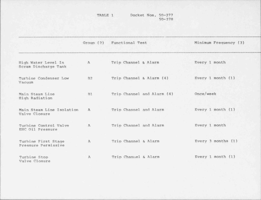
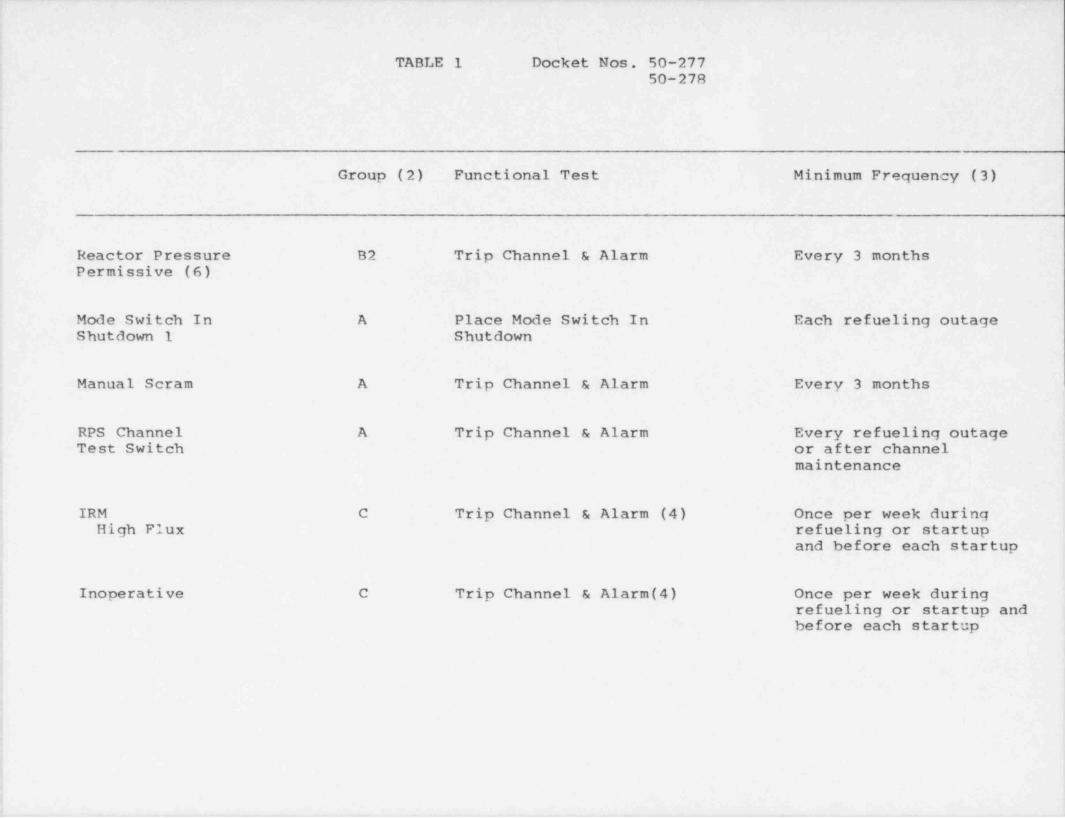
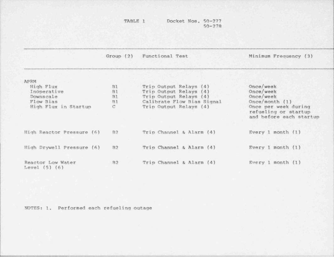
On-line functional testing of the reactor protectionsystem instrument and control circuits is performed atthe frecuencies stated in Table 1 for Peach Bottom Units2 and 3. The sensors, channels and logics of the RPSare not used in the process control system. Therefore,failure in the controls and instrumentation of nrocesssystems cannot induce failure of any nortion of the RPSsystem.
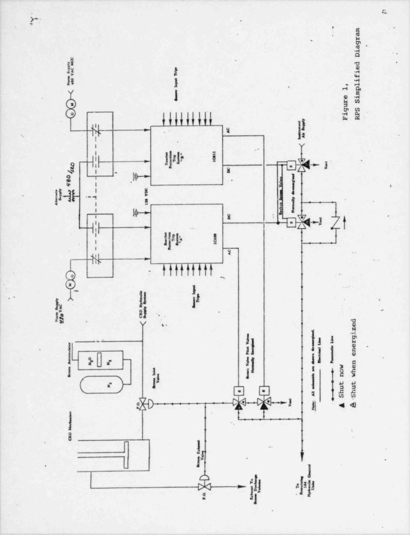
The Peach Bottom RPS is arranged as a one-out of twotaken twice. The arrangement of the Peach Bottom RPS isshown in Fiqure 1. Theoretically, its reliability toinitiate a scram is slightly higher than a two-out-of-three system and slightiv lower than a one-out-of-twosystem. However, with the dual trip system arrangement,it can be tested during reactor onoration withoutcausing a scram.
The RPS trip system is tested durinq reactor onerationby the following senarate tests. The first of these isthe manual trip actuator test. By denressing the manualscram button for one trin system, the manual logicactuators are de-engergized, onening contacts in theactuator logics. After resetting the first trip system,the second trin system is tripped with the other manualscram button. The total test verifies the ability tode-energize all eight groups of scram nilot valvesolenoids by using the manual scram nush buttonswitches. Scram aroun indicator lights verifv that theactuator contacts have opened.
The second test is the automatic actuator test which isaccomplished by onerating, one at a time, the kevlockedtest switches for each automatic logic. The switch de-engergizes the actuators for that logic, causing theassociated actuator contacts to open. The test verifiesthe ability of each logic to de-enerqize the actuatorlogics associated with the narent trin system. Theactuator and contact action can be verified by obcervingthe alarming of a tripned condition of these devices.
The third test includes calibration of the neutronmonitoring system by means of simulated inputs fromcalibration signal units.
. - . - - - - _. -, , . _. . . - - _ .
_. - - .- . , . - -.. _. - .
I
1
j
Mr. D. G. Eisenhut November 4, 1083| Docket Nos. 50-277 Page 36
i 50-278
|
.
The last test involves the applicttion of~a test sionalto each RPS channel in turn and observing that a logictrip results. This test also verifies the electricalindependence of the channel circuitry. The test signalscan be applied to the process type sensing instruments(pressure and differential pressure) through calibrationtaps.
.
The scram pilot valves are tested after each refuelingoutage during the operational hydro or during startupwith system pressure > 800 psig. This test is to becompleted for all fully withdrawn operable control rodsprior to synchronizinq the turbine generator.
After exceeding 30% power and prior to exceeding 40%,
power, all of the untested operable control rods aretested. This surveillance requirement is performed by
- manually scramming the individual rod by operating itstoggle test switch in the control room. During thistest, the individual rod scram insertion time iscalculated. The rod scram insertion time is calculated4
J based on the de-engergization of the scram pilot valvesolenoids as being time "zero". Any failure of a scram
i pilot valve will result in unacceptable scram insertioni time for the particular control rod which must bei remedied prior to full power operation.1
} The backup scram valves are tested each refueling outageto avoid spurious full scrams. The scram pilot valveinstrument air header should be maintained between 65psig and 75 psig. In order to test the backup scram
: valves, a special header arrangement is required to be
|connected to each set of backup scram valves. Thisheader arrangement is connected to the vented part of;
' the backup scram valves and contains a pressure gauge tomeasure the pressure increase as a result of the ventingof the valves when it receives a similated scram signal.,
The header arrangement also serves to prevent the scrampilot valve instrument air header from depressurizing.
|
If this header pressure drops below apnroximately 25! psig, the scram valves will onen, scramming rods in.
Special precautions must be taken when utilizing this.
special header arrangement to prevent depressurizing ofiI air headers when nerforming this test. Since the
testing frequency is essentially the same for the backun:
scram valves as for the scram pilot valves and becauseof the increased likelihood of spurious full scrams due
,
d
1
e -, t-e-S-tv-v+,ow- ---w--r-1m +--,=*w---e---e= ,,--- ---- -+, e -1,-r --rw--w+,.r. -v-g-% y-m.*---e s www -v--,,.yyw,y- ~ , m 7-+ ym . w ww - g y-w- *w m e ,<ym%* -~--~e.

Mr. D. G. Eisenhut November 4, 1993Docket Nos. 50-277 Pace 37
50-27R
to the nature of this testing, on-line functionaltesting of the backup scram valves is not justified.
Functional testing frecuencies for the RPS instrumentand control circuits are as stated in Table I attached.
n
_- _ _ . . . .
1
. [
y! .A
.'
, s
. m.
'. a
re ga .
iD e
g .
d #
eg.W is,
f4 ipm , lI . 1 pe
m... e i.
S r Sug Si PF Rcm , C2 = _' y
a,. - e
e
*q 1[ . c _sA" _k
.A- 1
.
- >x.,
-s
"5t
IL_ - 9
,
i v
._ e- f
cA" ,.-a
.
.- c
/ - a&
.Ee.0. - .
8 '_ c
f ._i - .
.
C- D -r.
6&. ee -
e r V.
n.' 2 r-
a.s S .o. 'S
A - . -I.
-,.-
E_ a
c ...
- a . ,, ;
-f N
,1j
lL- l 1
,'
-_
e. st
"Ae
.
se se c
. n. i
_
gp
cA
-if .
,r- ? ; : : _'_ '
*
J
os. '
n
[ - .ay " ' v.i
g,
.gc H auSav De4 R ,s Cef ,' dNy . /\ ef
zi.
. . g. _ . .
v* 8 n.
s. . u r, ,.uw e~
s. ' =. e *r e e,
"3 i ur e. m*. *
= , v '"" a - n3 b^ " w e.
= . " *e
= . .: o h= .
.a . . n we
YAt.v : t t3
"- J_
u u1J:
B h hr'L L A S S. : -7 . .
g A6.J F v
_
^'
-
-oac
- ,*
.
* -'..* ~.
..
s 1
s
s... O. g
* .
2.m e. o "i
.e' n. ,,i.t
JU . oo .
'.Iv .
a. A.p
Mr
s
-
, i ,. 1
. _ _ _ _ _ _
TABLE 1 Docket Nos. 50-27750-278
Group (2) Functional Test Minimum Frequency (3)
High Water Level In A Trip Channel & Alarm Every 1 monthScram Discharge Tank
Turbine Condenser Low B2 Trip Channel & Alarm (4) Every 1 month (1)Vacuum
Main Steam Line B1 Trip Channel and Alarm (4) Once/ weekHigh Radiation
Main Steam Line Isolation A Trip Channel and Alarm Every 1 month (1)Valve Closure
Turbine Control Valve A Trip Channel and Alarm Every 1 monthEHC Oil Pressure
Turbine First Stage A Trip Channel & Alarm Every 3 months (1)Pressure Permissive
Turbine Stop A Trip Channel & Alarm Every 1 month (1)Valve Closure
. . . . . - .-.
i
TABLE 1 Docket Nos. 50-27750-278
,
!
Group (2) Functional Test Minimum Frequency (3)
Reactor Pressure B2 Trip Channel & Alarm Every 3 monthsPermissive (6)
Mode Switch In A Place Mode Switch In Each refueling outageShutdown 1 Shutdown
!
Manual Scram A Trip Channel & Alarm Every 3 months
RPS Channel A Trip Channel & Alarm Every refueling outageTest Switch or after channel
maintenanceI
j
j IRM C Trip Channel & Alarm (4) Once per week duringa High Flux refueling or startup'
and before each startup
| Inoperative C Trip Channel & Alarm (4) Once per week during] refueling or startup and
before each startup,
,
1
;
.
,
1
.-
_ _ _ _ - _ _ - __
'
TABLE 1 Docket Nos. 50-27750-278
Group (2) Functional Test Minimum Frequency (3)
APRMHigh Flux B1 Trip Output Relays (4) Once/ weekInoperative B1 Trip Output Relays (4) Once/ weekDownscale B1 Trip Output Relays (4) Once/ week
| Flow Bias B1 Calibrate Flow Bias Signal Once/ month (1); High Flux in Startup C Trip Output Relays (4) Once per week during
refueling or startupand before each startup
: High Reactor Pressure (6) B2 Trip Channel & Alarm (4) Every 1 month (1)4
High Drywell Pressure (6) B2 Trip Channel & Alarm (4) Every 1 month (1)
Reactor Low Water B2 Trip Channel & Alarm (4) Every 1 month (1)Level (5) (6)
NOTES: 1. Performed each refueling outage
Docket Nos. 50-27750-278
TABLE 1
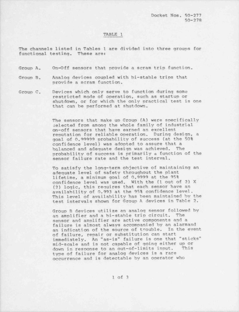
The channels listed in Tables 1 are divided into three groups forfunctional testing. These are:
Group A. On-Off sensors that provide a scram trip function.
Group B. Analog devices coupled with bi-stable trips thatprovide a scram function.
Group C. Devices which only serve to function during somerestricted mode of operation, such as startup orshutdown, or for which the only practical test is onethat can be performed at shutdown.
The sensors that make un Group (A) were specificallyselected from among the whole family of industrialon-off sensors that have earned an excellentreputation for reliable operation. During design, agoal of 0.99999 probability of success (at the 50%confidence level) was adopted to assure that abalanced and adequate design was achieved. Theprobability of success is primarily a function of thesensor failure rate and the test interval.
To satisfy the long-term objective of maintaining anadequate level of safety throughout the plantlifetime, a minimum goal of 0.9999 at the 95%confidence level was used. With the (1 out of 2) X(2) logic, this requires that each sensor have anavailability of 0.993 at the 95% confidence level.This level of availability has been maintained by thetest intervals shown for Group A devices in Table 2.
Group B devices utilize an analog sensor followed byan amplifier and a bi-stable trip circuit. Thesensor and amplifier are active components and afailure is almost always accompanied by an alarmandan indication of the source of trouble. In the eventof f ailure, repair or substitution can startimmediately. An "as-is" failure is one that " sticks"mid-scale and is not capable of going either up ordown in response to an out-of-limits input. Thistype of failure for analog devices is a rareoccurrence and is detectable by an operator who
1 of 3
. - -. - . _ . - __ . . _ . . _ _ . _ _ __ ___
- . . . - . ._ -_. .- .. . - - - _ _ _ - . . . -
_
i
Docket Nos. 50-277.
| 50-278
!TABLE l'
'
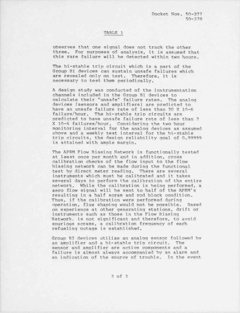
observes that one signal does not track the otheri three. For purposes of analysis, it is assumed that
this rare failure will be detected within two hours.'
The bi-stable trip circuit which is a part of theGroup B1 devices can sustain unsafe failures which
| are revealed only on test. Therefore, it isi necessary to test them periodically.
A design study was conducted of the instrumentationi channels included in the Group B1 devices to
calculate their " unsafe" failure rates. The analog"
devices (sensors and amplifiers) are predicted to'
have an unsafe failure rate of less than 20 X 10-6failure / hour. The bi-stable trip circuits are'
I predicted to have unsafe failure rate of less than 2i X 10-6 failures / hour. Considering the two hour; monitoring interval for the analog devices as assumed
above and a weekly test interval for the hi-stabletrip circuits, the design reliability goal of 0.999993
|- is attained with ample margin.
The APRM Flow Biasing Network is functionally tested'
at least once per month and in addition, crosscalibration checks of the flow input to the flow,
| biasing network can be made during the functionaltest by direct meter reading. There are severalinstruments which must be calibrated and it takes#
I several days to perform the calibration of the entirenetwork. While the calibration is being performed, azero flow signal will be sent to half of the APRM'sresulting in a half scram and rod block condition.Thus, if the calibration were performed duringoperation, flux shaping would not be possible. Basedon experience at other generating stations, drift or,
: instruments such as those in the Flow Biasing'
Network. is not significant and therefore, to avoid| spurious scrams, a calibration frequency of each
refueling outage is established.,
;
! Group B2 devices utilize an analog sensor followed byan amplifier and a bi-stable trip circuit. The;'sensor and amplifier are active components and afailure is almost always accompanied by an alarm and;
,an indication of the source of trouble. In the event
4
1
1 2 of 3i
,
i
e
__. _ _ . .__ _ m, . _ , .. _ _ _ ,.. _ _ _ . _ ,,,,. _ , _ _ ._,__,,, _ . - . . _ , . _ _ _ _ . _ , _ , _ , _ _ _ _ . - - . .
- - _-
Docket Nos. 50-27750-278
TABLE 1
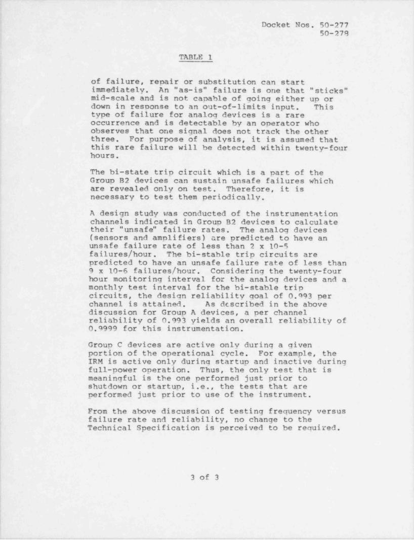
of failure, repair or substitution can startimmediately. An "as-is" failure is one that " sticks"mid-scale and is not capable of going either up ordown in resoonse to an out-of-limits input. Thistype of failure for analog devices is a rareoccurrence and is detectable by an operator whoobserves that one signal does not track the otherthree. For purpose of analysis, it is assumed thatthis rare failure will be detected within twenty-fourhours.
The bi-state trip circuit which is a part of theGroup B2 devices can sustain unsafe failures whichare revealed only on test. Therefore, it isnecessary to test them periodically.
-'
A design study was conducted of the instrumentationchannels indicated in Group B2 devices to calculatetheir " unsafe" failure rates. The analog devices(sensors and amplifiers) are predicted to have an
i unsafe failure rate of less than 2 x 10⁻⁵failures / hour. The bi-stable trip circuits arepredicted to have an unsafe failure rate of less than9 x 10-6 failures / hour. Considering the twenty-fourhour monitoring interval for the analog devices and amonthly test interval for the bi-stable tripcircuits, the design reliability goal of 0.993 perchannel is attained. As dcscribed in the abovediscussion for Group A devices, a per channelreliability of 0.993 yields an overall reliability of'
0.9999 for this instrumentation.
Group C devices are active only during a given| portion of the operational cycle. For example, the| IRM is active only during startup and inactive during
full-power operation. Thus, the only test that ismeaningful is the one performed just prior toshutdown or startup, i.e., the tests that areperformed just prior to use of the instrument.
From the above discussion of testing frequency versusfailure rate and reliability, no change to theTechnical Specification is perceived to be required.
3 of 3
|
-- , - . . . . - - -. , - - , - - .-- - -, . . . , . - . , - - . - , - - , , - - , - - .- -
. - -
Mr. D. G. Eiesnhut November 4' 1983Docket Nos. 50-277 Pago 41
50-278
We trust that the information contained in the aboveresponses is sufficient for Nuclear Regulatory Commission reviewof Philadelphia Electric Company's current conformance with thepositions stated in Generic Letter 83-28. In accordance with theReference #2 letter, we have provided, to the best of ourknowledge, our current status regarding the NRC positions inGeneric Letter 83-28. Where appropriate, schedules to achieveconformance with these positions have been proposed. We havealso provided an explanation for those items for which we cannotprovide implementation schedules at this time, and have specifiedwhen these NRC positions will be addressed.
Should you require any further information, please donot hesitate to contact us.
Very truly yours,
? )
'A~
Attachments
cc: A. R. Blough, Site Inspector
, - . - , . . ,. -.-.., -. , ._- ,. . ._. ,---- ...--- , .- ,.--- .,--..--,,,_..--,-,-v,.--,, ,,-
. - .. =- - . . . . . .- - . . _- . .
I
!
COMMONWEALTH OF PENNSYLVANIA :
: ss.
COUNTY OF PHILADELPIIIA :
i
: S. L. Daltrof f, being fi'.st duly sworn, deposes and says:;
That he is Vice President of Philadelphia Electric
Company, the Applicant herein; that he has read the foregoing
response to Generic Letter 83-28, and knows the contents thereof;
and that the statements and matters set forth therein are true| and correct to the best of his knowledge, information and belief .
!.
~/& ij ,
f / e' -
,
1;
Subscribed and sworn to;
i 1%,
before me this i day
of lN '% '
:
i
kbtus.- ? is/ /
Notary Publi'c
,
PATRICIA A. JONESNotary Pubhc, Phila., Phila. Co.'
My Commission Expires Oct. 13,1906
i1
i
S
-ew * v ns -te - m w-, - = -e- ew -w.,wm-w,m ----,,wwow, ,r~- =--sr e- .-e--,.we.,w--r,w re~,,,--r,-c.,r3-,-.--wewd-cw-.y e -r-w w ry-e-r---==--,p--.ww em s -y
Related Documents


