34 th International Symposium on Automation and Robotics in Construction (ISARC 2017) Automated Ergonomic Risk Assessment based on 3D Visualization X. Li a , S. Han b , M. Gül c and M. Al-Hussein d a PhD Candidate, Department of Civil and Environmental Engineering, University of Alberta, Canada b Assistant Professor, Department of Building, Civil and Environmental Engineering, Concordia University, Canada c Assistant Professor, Department of Civil and Environmental Engineering, University of Alberta, Canada d Professor, Department of Civil and Environmental Engineering, University of Alberta, Canada E-mail: [email protected], [email protected], [email protected], [email protected] Abstract – Conventional ergonomic risk assessment of physical work is conducted through observation and direct/indirect physiological measurements. However, these methods are time-consuming and require human subjects to actually perform the motion in order to obtain detailed body movement data. 3D visualization, alternatively, allows users to simulate an operational task on the computer screen, a process that is less time- consuming and which eliminates the need for costly on- site devices, as well as the detrimental effect of human error during experimentation. It can also proactively visualize a proposed design prior to implementation in the real world. This paper presents an automated ergonomic risk assessment framework based on 3D modelling with the support of a user-friendly interface for data-post processing. 3ds Max is utilized together with its built-in MAXScript. The presented system enables the automation of body motion risk identification by detecting awkward body postures, evaluating the handled force/load and frequency that cause ergonomic risk during body movements of workers. As the outcome, it provides detailed risk scores for body segments, such that users are able to review the continuous motion and corresponding risk by precise time frame. The capability of this 3D visualization- based ergonomic risk assessment can be extended to support the re-design of the workplace and optimization of human body movement accordingly. The ultimate goal of this study is to proactively mitigate ergonomic risk and further reduce potential injuries and workers’ compensation insurance costs in the long term. Keywords – Ergonomics, 3D Visualization, Risk Assessment, 3ds Max, Automation 1 Introduction The Association of Workers’ Compensation Boards of Canada reports that the manufacturing and construction industries had the second and third highest number of lost-time claims due to injuries in 2015, accounting for 14% and 11%, respectively, of total workplace injury claims (232,629) in Canada [1]. In the United States, the manufacturing and construction industries accounted for 11% and 7%, respectively, of all nonfatal occupational injuries and illnesses in 2015 [2]. Thus, improving workplace safety practice in order to reduce work-related injuries in the manufacturing and construction industries is a top priority. Traditional measures to assess work movements during operation rely on direct manual observation and self-report, which are inherently subjective, time- consuming, and error-prone. Researchers also invest in both direct and indirect physiological measurements in order to collect human body data for ergonomic and biomechanical analyses, which provide results that are more objective, detailed, and accurate than traditional metrics. Body movements can be obtained by utilizing goniometers, accelerometers, and optimal markers. In order to analyse muscle activity, electromyography (EMG) is commonly used to indicate muscle fatigue [3][4][5][6]. However, these measurements all entail job interruption. The solution, then, is to conduct indirect physiological measurement by means of a Kinect range camera or computer vision-based approach, which is also commonly used to capture motion and to conduct body posture assessment [7][8][9][10][11]. Some studies use a video-based computer visualization approach to automatically assess the captured motion [11][12]. However, all of these measurements have limitations in the real-life implementation in construction manufacturing, such as illumination and obstacles in the capturing direction, and the data post- processing is also time consuming [13][14]. Alternatively, human subjects are commonly utilized to simulate tasks in a laboratory setting in order to imitate the task, with direct and indirect measurements employed to capture the motion and to record

Welcome message from author
This document is posted to help you gain knowledge. Please leave a comment to let me know what you think about it! Share it to your friends and learn new things together.
Transcript

34th International Symposium on Automation and Robotics in Construction (ISARC 2017)
Automated Ergonomic Risk Assessment based on 3D Visualization
X. Lia, S. Hanb, M. Gülc and M. Al-Husseind
aPhD Candidate, Department of Civil and Environmental Engineering, University of Alberta, Canada bAssistant Professor, Department of Building, Civil and Environmental Engineering, Concordia University, Canada
cAssistant Professor, Department of Civil and Environmental Engineering, University of Alberta, Canada dProfessor, Department of Civil and Environmental Engineering, University of Alberta, Canada
E-mail: [email protected], [email protected], [email protected], [email protected] Abstract –
Conventional ergonomic risk assessment of physical work is conducted through observation and direct/indirect physiological measurements. However, these methods are time-consuming and require human subjects to actually perform the motion in order to obtain detailed body movement data. 3D visualization, alternatively, allows users to simulate an operational task on the computer screen, a process that is less time-consuming and which eliminates the need for costly on-site devices, as well as the detrimental effect of human error during experimentation. It can also proactively visualize a proposed design prior to implementation in the real world. This paper presents an automated ergonomic risk assessment framework based on 3D modelling with the support of a user-friendly interface for data-post processing. 3ds Max is utilized together with its built-in MAXScript. The presented system enables the automation of body motion risk identification by detecting awkward body postures, evaluating the handled force/load and frequency that cause ergonomic risk during body movements of workers. As the outcome, it provides detailed risk scores for body segments, such that users are able to review the continuous motion and corresponding risk by precise time frame. The capability of this 3D visualization-based ergonomic risk assessment can be extended to support the re-design of the workplace and optimization of human body movement accordingly. The ultimate goal of this study is to proactively mitigate ergonomic risk and further reduce potential injuries and workers’ compensation insurance costs in the long term.
Keywords –
Ergonomics, 3D Visualization, Risk Assessment, 3ds Max, Automation
1 Introduction The Association of Workers’ Compensation Boards
of Canada reports that the manufacturing and construction industries had the second and third highest number of lost-time claims due to injuries in 2015, accounting for 14% and 11%, respectively, of total workplace injury claims (232,629) in Canada [1]. In the United States, the manufacturing and construction industries accounted for 11% and 7%, respectively, of all nonfatal occupational injuries and illnesses in 2015 [2]. Thus, improving workplace safety practice in order to reduce work-related injuries in the manufacturing and construction industries is a top priority.
Traditional measures to assess work movements during operation rely on direct manual observation and self-report, which are inherently subjective, time-consuming, and error-prone. Researchers also invest in both direct and indirect physiological measurements in order to collect human body data for ergonomic and biomechanical analyses, which provide results that are more objective, detailed, and accurate than traditional metrics. Body movements can be obtained by utilizing goniometers, accelerometers, and optimal markers. In order to analyse muscle activity, electromyography (EMG) is commonly used to indicate muscle fatigue [3][4][5][6]. However, these measurements all entail job interruption. The solution, then, is to conduct indirect physiological measurement by means of a Kinect range camera or computer vision-based approach, which is also commonly used to capture motion and to conduct body posture assessment [7][8][9][10][11]. Some studies use a video-based computer visualization approach to automatically assess the captured motion [11][12]. However, all of these measurements have limitations in the real-life implementation in construction manufacturing, such as illumination and obstacles in the capturing direction, and the data post-processing is also time consuming [13][14]. Alternatively, human subjects are commonly utilized to simulate tasks in a laboratory setting in order to imitate the task, with direct and indirect measurements employed to capture the motion and to record

34th International Symposium on Automation and Robotics in Construction (ISARC 2017)
physiological data for further ergonomic analysis. It should be noted that laboratory-based simulation can represent tasks with a reasonable level of detail and accuracy (comparing alternative methods), and can thereby facilitate effective ergonomic risk assessment (providing adequate information as the input to these risk assessment tools). However, a laboratory setting will have space limitations compared to the field, and thus can only accommodate the simulation of elemental tasks. In addition, the experimentation in such a setting is typically subject to ethical, technical, and cost issues, and it also requires time-consuming data post-processing and a large number of subjects to imitate the motions and activities being evaluated [15]. The need is thus increasing for a new method which can overcome these difficulties and eliminate work interruption on the job in order to automatically identify whether ergonomic risk is increasing.
Li et al. propose a framework of using 3D-motion based modelling to assess human body posture and ergonomic risk with the integration of the existing risk assessment tools, Rapid Entire Body Assessment (REBA) and Rapid Upper Limb Assessment (RULA) [16][17]. The present paper extends this framework and proposes an automated platform for its implementation. The objective of this methodology is to develop a user-friendly interface to visualize the risk assessment and analysis and to help with proposing modified task motions accordingly in order to reduce potential work-related claims and injuries. This framework streamlines the ergonomic risk assessment process and provides easy access to read and compare the analysis results effectively and quickly with graphs and animations. The framework can also be used to evaluate proposed changes to workstations at the design phase.
2 Automation of the 3D motion-based Ergonomic Risk Assessment
The presented framework is explained in Figure 1, with the 3D human body model and user manual input as the two types of data input to the framework. In this research, 3ds Max is chosen to create human body working motion animations, which includes the animation of the biped to imitate human movement in a construction manufacturing facility [18]. The biped can be controlled by altering the length and speed of footsteps, the body posture key frames, and the frame rates. From the 3D human body model, the human body joint angles and REBA/RULA risk assessments are calculated in the MAXScript, the built-in language in 3ds Max software, in conjunction with the programming code [19]. A user interface is developed to collect the input data (time frame selection, force/load data and activity performance score selection) needed to
calculate the script. Functional tablet buttons in the interface are linked to the script in order to calculate the joint angle once the needed data has been entered. These functional tablet buttons can also open windows to display the results.
3D human body model
User interface Joint angles Time frame input Force input data Activity score
Function buttons Data post-processing REBA/RULA script
Collection of DLL’s Joint angles Risk ratings
Window OxyPlot (graphs) Grid (risk levels) Pictures (body postures) Media player (animation)
Data acquisition Joint angle calculation
script
User input
Figure 1. Automated ergonomic risk assessment
framework
2.1 Data acquisition In the model, to obtain the body posture joint angles
for various body postures and movements, a total of 26 bones in the biped, as listed in Table 1, must be satisfied, and “footsteps” must be selected before running the programmed MAXScript code. Moreover, world coordinate system is used to define the joint angle of the pelvis, local coordinate system is used to determine the joint angle of the other body segments (vertical angle and horizontal angle), and gimbal coordinate system is used in calculating the rotation of the body segments. In addition, inverse kinematics method is employed to identify the moving direction of the subject during the animation. It is also applied during the animation creation, as this function reverses the direction of the chain manipulation and facilitates the creation of the animation.
The calculation of joint angles for the presented method (referring to the “3D Static Strength Prediction Program” developed at the University of Michigan in 2012 [20]) differs from the calculation required by REBA and RULA. Thus, a conversion of joint angles among different scenarios is conducted to fit the REBA/RULA requirements. In total, 41 joint angles are obtained from the 3D model. By selecting the range of the animation time frame and running MAXScript to make the calculation, joint angles for body segments can be captured by each frame of the 3D animation in batch files.

34th International Symposium on Automation and Robotics in Construction (ISARC 2017)
Table 1 List of bones in the biped
List of bones in the biped Pelvis Spine
Left/Right thigh Left/Right calf Left/Right foot Left/Right toe
Neck Left/Right clavicle
Left/Right upper arm Left/Right forearm
Left/Right hand Left/Right 3 finger bones
Head
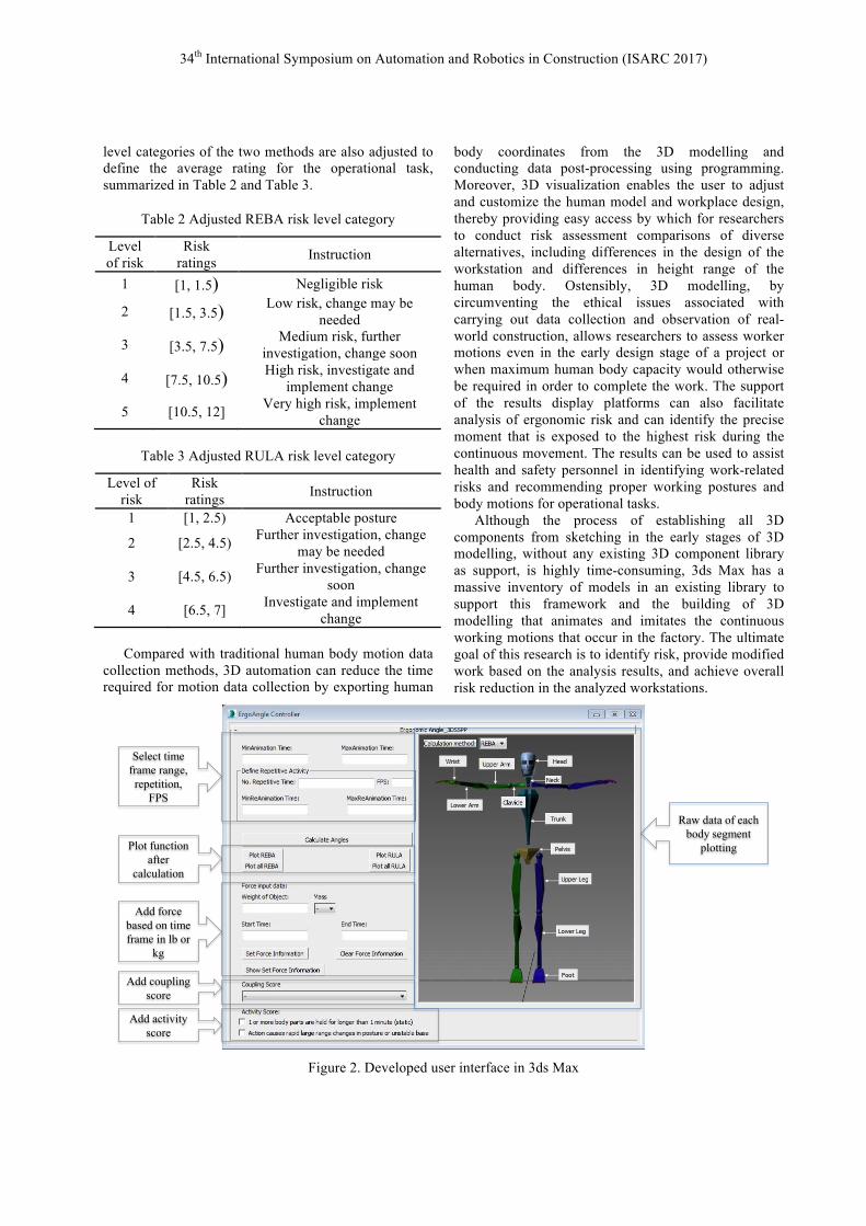
2.2 Data-post processing A user interface, as displayed in Figure 2, is
developed for the purpose of conducting data post-processing and further analysing the results. With the support of other platforms (to be described later in this section), a user interface in 3ds Max is developed. It is not necessary to analyse the entire model in 3ds Max; the analysed time frames can be defined and selected by the user as needed. The repetitive motion in the animation can also be edited by typing in the time frame range and the number of the repetition, which also generates a repetition score for the motion, which needs to be repeated 4 times per minute. Based on Equation (1), if the total duration of the task is less than 60 seconds, then an activity score of 1 is added to the total rating. Total duration = Total time frame/Frame rateÎ4 (1)
Note: The frame rate default is set to 30 frames per second and can be customized by the user.
The inputs of the interface are the time frame range of the task to be analyzed, the time frame range of the repetitive motion within this time frame to be specifically evaluated, the number of repetitions of this repetitive motion time frame, the handled force (in pounds or kilograms), the time frame range of force implementation, the coupling score, and the activity score. For the input of handled force, users can also type in multiple entries by inputting force and time frame range data one by one. To check all the force input settings, the function of “show set force information” is also available. The function of clearing all the force input settings in the event of erroneous inputs is also provided. In terms of the coupling score, a drop-down list is designed where the user may select among: “Well fitting handle and mid-range power grip”, “Acceptable but not ideal hand hold or coupling acceptable with another body part”, “Hand hold not acceptable but possible”, or “No handle, awkward, unsafe with any
body part”. Within the activity score, a repetition score is calculated as per Equation (1), and check boxes are also included as follows: “1 or more body parts are held for longer than 1 minute (static)” and “action causes rapid large range changes in posture or unstable base”, as shown in the bottom of Figure 2.
Following the joint angle conversion, the angles can be directly implemented in REBA and RULA. The risk rating is calculated using MAXScript programming to read the generated batch file, and is graphically plotted for each individual body segment (including trunk, neck, arm, leg, and wrist), as well as for the total rating of the entire motion at the respective time frame, considering force/load and activity performance.
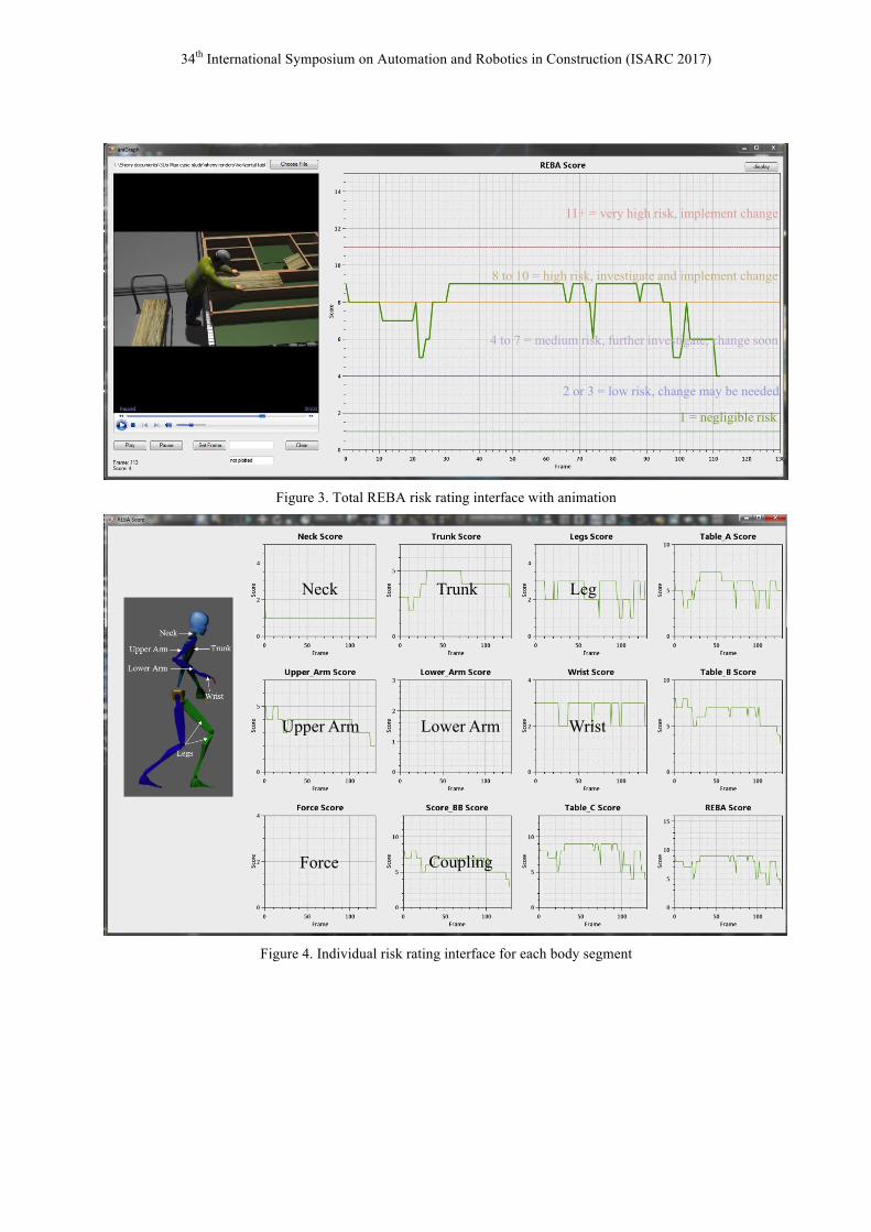
OxyPlot is used as an open source plotting library for .NET. A Dynamic-link Library (DLL) is created to receive information from 3ds Max, and then OxyPlot in conjunction with WindowsForm is applied in order to provide a graphical representation. Windows Media Player is utilized to play the rendered animation of the human body movement. Any high-risk motions can be identified through this rating algorithm and the resulting plotted chart. The peak rating and the corresponding human body motion are identified by comparing the plotted chart with the animation, illustrated in Figure 3. The plotted chart is displayed based on the time span of the animation (i.e., the next risk rating to be displayed in the chart illustrates the rating of the motion in the animation at the given timeframe). Buttons for pausing the animation and dragging the animation to a certain time frame or footage are also developed for the purpose of viewing the risk at play at a certain time frame. The user can also type in the time frame to check the risk rating accordingly.
Moreover, risk ratings are plotted for each body segment, and this assists in providing understanding of which body segments are exposed to higher risks during the given operation, as indicated in Figure 4. Modified work can be recommended for the given motion by revising the task manoeuvre of the body segment with a high rating or modifying the task manoeuvre entirely.
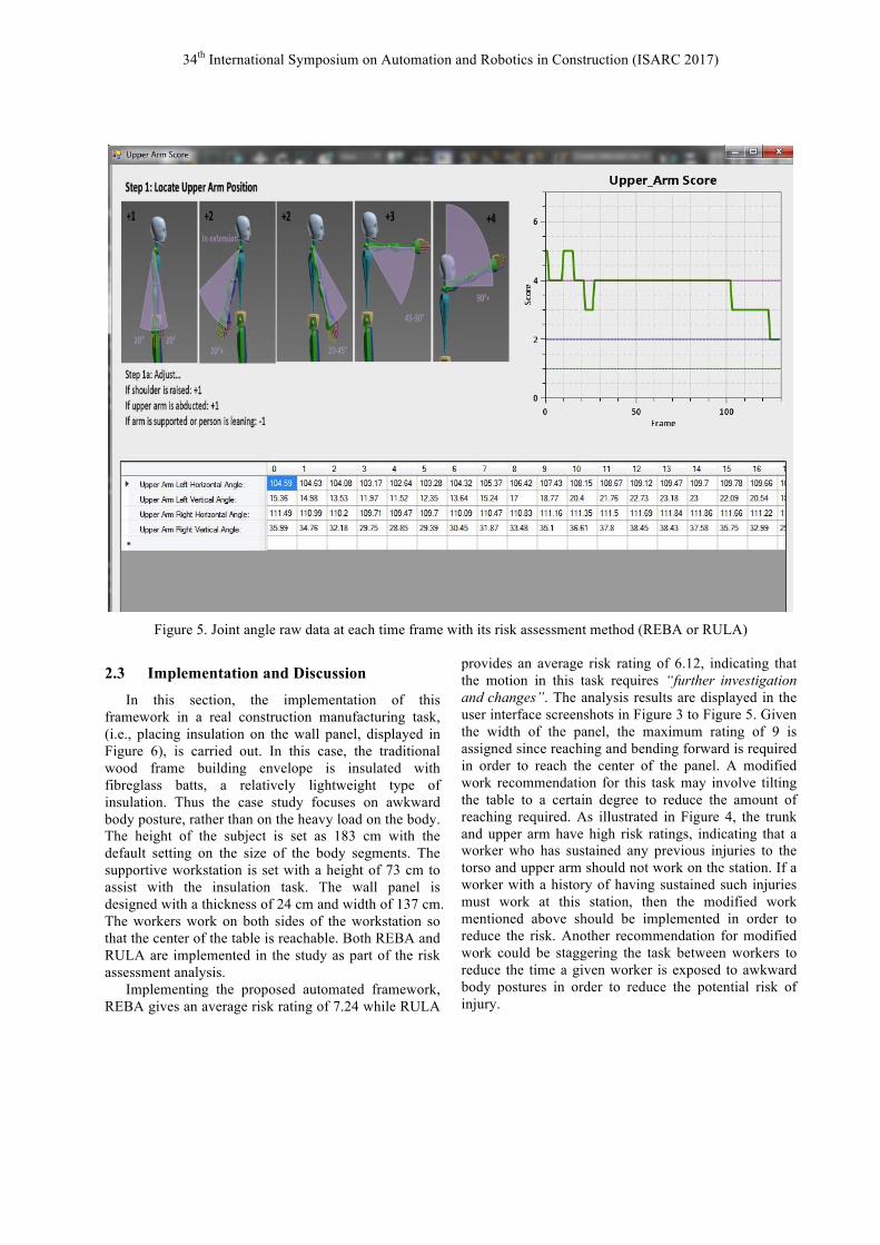
A function for plotting joint angle raw data together with its risk assessment method and results is also developed (appearing on the right side of the user interface shown in Figure 2). When the user selects the REBA/RULA calculation method and clicks the body segment button, an interface appears for plotting and displaying raw data of each time frame. This function enables the user to check the raw data and risk assessment results for either REBA or RULA, as indicated in Figure 5.
The result from the traditional usage of REBA and RULA methods is given as an integer. However, in this framework, the obtained risk rating result is averaged among a certain range of time frames. Thus, the risk
34th International Symposium on Automation and Robotics in Construction (ISARC 2017)
level categories of the two methods are also adjusted to define the average rating for the operational task, summarized in Table 2 and Table 3.
Table 2 Adjusted REBA risk level category
Level of risk
Risk ratings Instruction
1 [1, 1.5) Negligible risk
2 [1.5, 3.5) Low risk, change may be needed
3 [3.5, 7.5) Medium risk, further
investigation, change soon
4 [7.5, 10.5) High risk, investigate and
implement change
5 [10.5, 12] Very high risk, implement change
Table 3 Adjusted RULA risk level category
Level of risk
Risk ratings Instruction
1 [1, 2.5) Acceptable posture
2 [2.5, 4.5) Further investigation, change may be needed
3 [4.5, 6.5) Further investigation, change soon
4 [6.5, 7] Investigate and implement change
Compared with traditional human body motion data
collection methods, 3D automation can reduce the time required for motion data collection by exporting human
body coordinates from the 3D modelling and conducting data post-processing using programming. Moreover, 3D visualization enables the user to adjust and customize the human model and workplace design, thereby providing easy access by which for researchers to conduct risk assessment comparisons of diverse alternatives, including differences in the design of the workstation and differences in height range of the human body. Ostensibly, 3D modelling, by circumventing the ethical issues associated with carrying out data collection and observation of real-world construction, allows researchers to assess worker motions even in the early design stage of a project or when maximum human body capacity would otherwise be required in order to complete the work. The support of the results display platforms can also facilitate analysis of ergonomic risk and can identify the precise moment that is exposed to the highest risk during the continuous movement. The results can be used to assist health and safety personnel in identifying work-related risks and recommending proper working postures and body motions for operational tasks.
Although the process of establishing all 3D components from sketching in the early stages of 3D modelling, without any existing 3D component library as support, is highly time-consuming, 3ds Max has a massive inventory of models in an existing library to support this framework and the building of 3D modelling that animates and imitates the continuous working motions that occur in the factory. The ultimate goal of this research is to identify risk, provide modified work based on the analysis results, and achieve overall risk reduction in the analyzed workstations.
Select time frame range, repetition,
FPS
Plot function after
calculation
Add force based on time frame in lb or
kg
Add coupling score
Add activity score
Raw data of each body segment
plotting
Figure 2. Developed user interface in 3ds Max
34th International Symposium on Automation and Robotics in Construction (ISARC 2017)
1 = negligible risk
2 or 3 = low risk, change may be needed
4 to 7 = medium risk, further investigate, change soon
8 to 10 = high risk, investigate and implement change
11+ = very high risk, implement change
Figure 3. Total REBA risk rating interface with animation
Neck Trunk Leg
Upper Arm Lower Arm Wrist
Force Coupling
Figure 4. Individual risk rating interface for each body segment
34th International Symposium on Automation and Robotics in Construction (ISARC 2017)
Figure 5. Joint angle raw data at each time frame with its risk assessment method (REBA or RULA)
2.3 Implementation and Discussion In this section, the implementation of this
framework in a real construction manufacturing task, (i.e., placing insulation on the wall panel, displayed in Figure 6), is carried out. In this case, the traditional wood frame building envelope is insulated with fibreglass batts, a relatively lightweight type of insulation. Thus the case study focuses on awkward body posture, rather than on the heavy load on the body. The height of the subject is set as 183 cm with the default setting on the size of the body segments. The supportive workstation is set with a height of 73 cm to assist with the insulation task. The wall panel is designed with a thickness of 24 cm and width of 137 cm. The workers work on both sides of the workstation so that the center of the table is reachable. Both REBA and RULA are implemented in the study as part of the risk assessment analysis.
Implementing the proposed automated framework, REBA gives an average risk rating of 7.24 while RULA
provides an average risk rating of 6.12, indicating that the motion in this task requires “further investigation and changes”. The analysis results are displayed in the user interface screenshots in Figure 3 to Figure 5. Given the width of the panel, the maximum rating of 9 is assigned since reaching and bending forward is required in order to reach the center of the panel. A modified work recommendation for this task may involve tilting the table to a certain degree to reduce the amount of reaching required. As illustrated in Figure 4, the trunk and upper arm have high risk ratings, indicating that a worker who has sustained any previous injuries to the torso and upper arm should not work on the station. If a worker with a history of having sustained such injuries must work at this station, then the modified work mentioned above should be implemented in order to reduce the risk. Another recommendation for modified work could be staggering the task between workers to reduce the time a given worker is exposed to awkward body postures in order to reduce the potential risk of injury.

34th International Symposium on Automation and Robotics in Construction (ISARC 2017)
Figure 6. Insulation placement on the wall panel
3 Conclusion This paper proposes an automated framework to
assess ergonomic risks for occupational tasks with the support of 3D modelling and a user-friendly interface in 3ds Max. The details of data acquisition and data post-processing are also interpreted mathematically and graphically. A case study of installing insulation in the wall panel in a modular construction manufacturing plant is described. The framework enables the analysis of entire body movement as well as movement of each body segment. The interface, together with the animation and plotted chart, helps with the identification of the highest risk ratings during the continuous movement. The analysis results also lead to recommendations to adjust the existing working conditions as well as provisions to reduce risk particularly for workers who have sustained injuries in the past that would make them especially vulnerable to ergonomic risks.
Having this automated platform, the 3D motion-based ergonomic risk assessment is thus efficient and intelligent. The developed automated platform benefits the user in the following ways: (1) capability and flexibility to conduct data acquisition and data post-processing, and (2) ability to provide visualization of the workstation risk assessment results and to help with proposing any changes made to the plant. The ultimate goal of this research is to achieve overall risk reduction in practice for any construction manufacturing operational tasks. Upon implementing the proposed modified work in real practice, the ergonomic risk rating of the production line can be expected to decrease.
Limitations The force/load information and activity scores for
REBA and RULA risk assessment in the framework presented herein require manual input from the user. Future efforts to identify the precise time frames of force/load on the human body model and to determine an activity score for the movement could improve the presented framework as a further step toward fully intelligent automation.
Acknowledgements The authors would like to acknowledge the support
from the Natural Sciences and Engineering Research Council of Canada (NSERC) through the Industrial Research Chair (IRC) program (File No. IRCPJ 419145-15). Special thanks are extended to Mr. Michael Sukkarieh, who helped with the development of the automated framework.
References [1] Workers’ Compensation Board (2015) “Employers
home: Modified work.” <https://www.wcb.ab.ca/return-to-work/> (accessed December, 2015)
[2] Bureau of Labor Statistics (2016). “Nonfatal occupational injuries and illnesses requiring days away from work, 2015.” Department of Labor. <https://www.bls.gov/news.release/pdf/osh2.pdf> (accessed February, 2017).
[3] González-Izal, M., Malanda, A., Navarro-Amézqueta, I., Gorostiaga, E.M., Mallor, F., Ibañez, J., and Izquierdo, M. (2010). “EMG spectral indices and muscle power fatigue during dynamic contractions.” Journal of Electromyography and Kinesiology, 20(2), 233–240.
[4] Mathieu, P.A., and Fortin, M. (2000). “EMG and kinematics of normal subjects performing trunk flexion/extensions freely in space.” Journal of Electromyography and Kinesiology, 10(3), 197–209.
[5] Kim, G., Ahad, M.A., Ferdjallah, M., and Harris, G.F. (2007). “Correlation of muscle fatigue indices between intramuscular and surface EMG signals.” Proceedings, IEEE SoutheastCon, pp. 378–382.
[6] Pah, N. and Kumar, D.K. (2001). “Classification of Electromyograph for Localised Muscle Fatigue Using Neural Networks.” Proceedings, Seventh Australian and New Zealand Intelligent Information Systems Conference, Perth, Australia, Nov. 18–21, pp. 271-275.
[7] Plantard, P., Shum, H. P.H., Le Pierres, A. and Multon, F. (2016). “Validation of an ergonomic

34th International Symposium on Automation and Robotics in Construction (ISARC 2017)
assessment method using Kinect data in real workplace conditions.” Applied Ergonomics, In Press.
[8] Khosrowpour, A., Niebles, J.C., and Golparvar-Fard, M. (2014). “Vision-based workface assessment using depth images for activity analysis of interior construction operations.” Automation in Construction, 48, 74–87.
[9] Alwasel, A., Elrayes, K., Abdel-Rahman, E. M., and Haas, C. T. (2011). “Sensing construction work-related musculoskeletal disorders (WMSDs).” Proceedings, International Association for Automation and Robotics in Construction (IAARC), London, UK, pp. 164-169.
[10] Ray, S. J. and Teizer, J. (2012). “Real-time construction worker posture analysis for ergonomics training.” Advanced Engineering Informatics, 26(2), 439–455.
[11] Han, S., and Lee, S. (2013). “A vision-based motion capture and recognition framework for behavior-based safety management.” Automation in Construction, 35, 131–141.
[12] Li, C. and Lee, S. (2011). “Computer vision techniques for worker motion analysis to reduce musculoskeletal disorders in construction.” Proceedings, International Workshop on Computing in Civil Engineering, Miami, FL, USA, Jun. 19-22, pp. 380–387.
[13] David, G. C. (2005). “Ergonomic methods for assessing exposure to risk factors for work-related musculoskeletal disorders.” Occupational Medicine, 55(3), 190–199.
[14] Li, G. and Buckle, P. (1999). “Current techniques for assessing physical exposure to work-related musculoskeletal risks, with emphasis on posture-based methods.” Ergonomics, 42(5), 674–695.
[15] Spielholz, P., Silverstein, B., Morgan, M., Checkoway, H., and Kaufman, J. (2001). “Comparison of self-report, video observation and direct measurement methods for upper extremity musculoskeletal disorder physical risk factors.” Ergonomics, 44(6), 588–613.
[16] Li, X., Han, S., Gül, M., and Al-Hussein, M. (2016). “3D motion-based ergonomic and body posture analysis in construction.” Proceedings, Modular and Offsite Construction (MOC) Summit, Edmonton, AB, Canada, Sep. 29–Oct. 1, pp. 215–223.
[17] Li, X., Han, S., Gül, M., Al-Hussein, M. and El-Rich, M. (submitted). “3D motion-based rapid ergonomic risk assessment framework and its validation method.” Journal of Construction Engineering and Management (Under review).
[18] Autodesk Inc. (2016). “Create amazing worlds in 3ds Max.”
<http://www.autodesk.com/products/3ds-max/overview-dts?s_tnt=69291:1:0> (accessed January 2017).
[19] Autodesk Inc. (2011). “MAXScript Introduction” <http://docs.autodesk.com/3DSMAX/14/ENU/MAXScript%20Help%202012/> (accessed January 2017).
[20] University of Michigan, Center of Ergonomics (2012). “3D static strength prediction program.” <http://djhurij4nde4r.cloudfront.net/attachments/files/000/000/284/original/Manual_606.pdf?1406656210> (accessed July, 2016).
Related Documents