Submillimeter Instrumentation Photo-detectors are no longer effective Submm astronomers use bolometers and heterodyne receivers.

Welcome message from author
This document is posted to help you gain knowledge. Please leave a comment to let me know what you think about it! Share it to your friends and learn new things together.
Transcript
Submillimeter Instrumentation
Photo-detectors are no longer effective Submm astronomers use bolometers and heterodyne receivers.
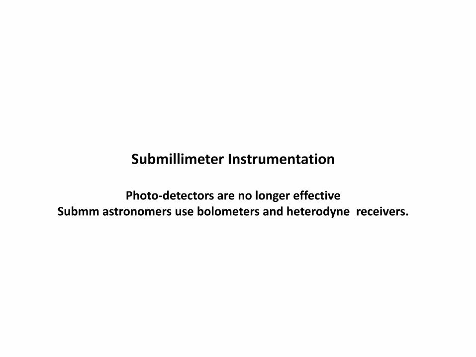
Bolometers
A bolometer consists of an absorber (efficiency ) attached to a thermometer, with both being connected to a heat sink by a weak thermal link of conductance G. The energy of the absorbed photons raises the temperature and the thermometer then gives a signal. The performance is characterized by the noise equivalent power (NEP), the power that can just be detected at rms signal to noise of 1 into a 1 Hz electronic bandwidth. Making G small increases the temperature excursion for a given power and tends to reduce the NEP (which is good). It also makes the detector slower (which is bad), as does high heat capacity, C:
)3(G
CT
where is the response time of the detector. Although there are other noise sources, the fundamental one is thermal noise due to phonons traversing the thermal link:
)2(
42/12
GkTNEPT
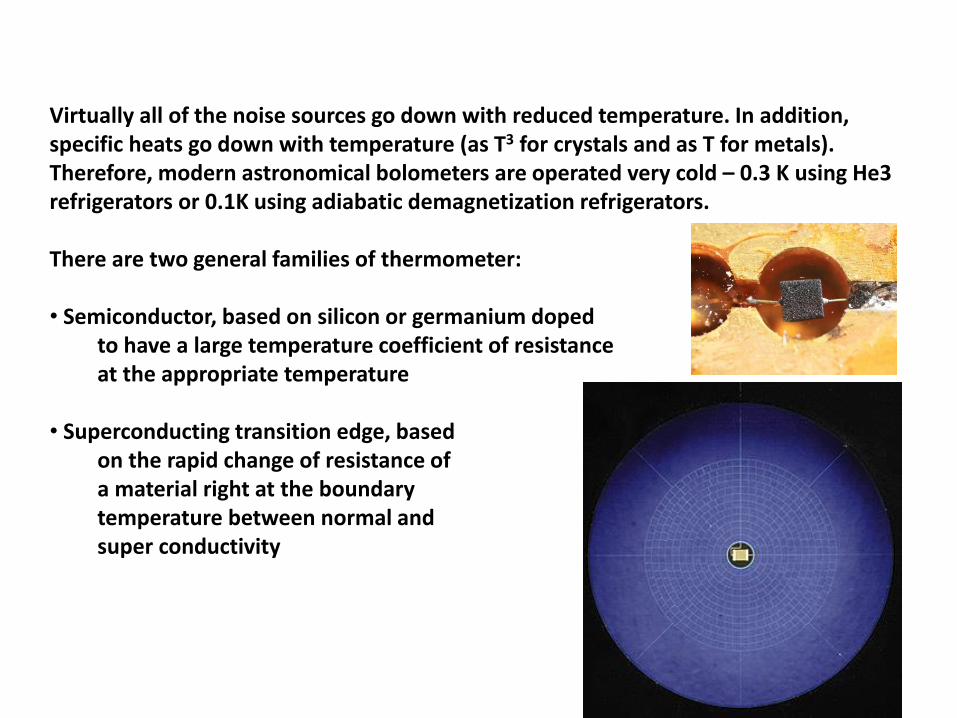
Virtually all of the noise sources go down with reduced temperature. In addition, specific heats go down with temperature (as T3 for crystals and as T for metals). Therefore, modern astronomical bolometers are operated very cold – 0.3 K using He3 refrigerators or 0.1K using adiabatic demagnetization refrigerators. There are two general families of thermometer: • Semiconductor, based on silicon or germanium doped
to have a large temperature coefficient of resistance at the appropriate temperature
• Superconducting transition edge, based on the rapid change of resistance of a material right at the boundary temperature between normal and super conductivity
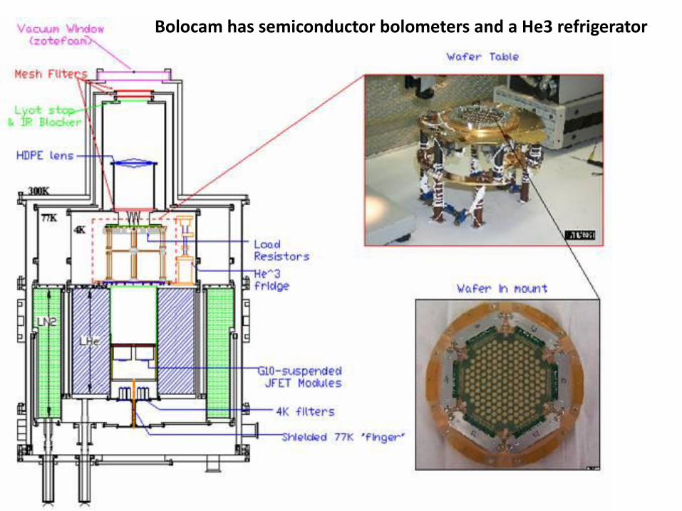
Bolocam has semiconductor bolometers and a He3 refrigerator
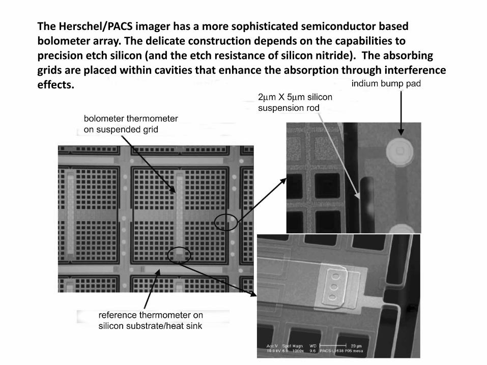
The Herschel/PACS imager has a more sophisticated semiconductor based bolometer array. The delicate construction depends on the capabilities to precision etch silicon (and the etch resistance of silicon nitride). The absorbing grids are placed within cavities that enhance the absorption through interference effects.
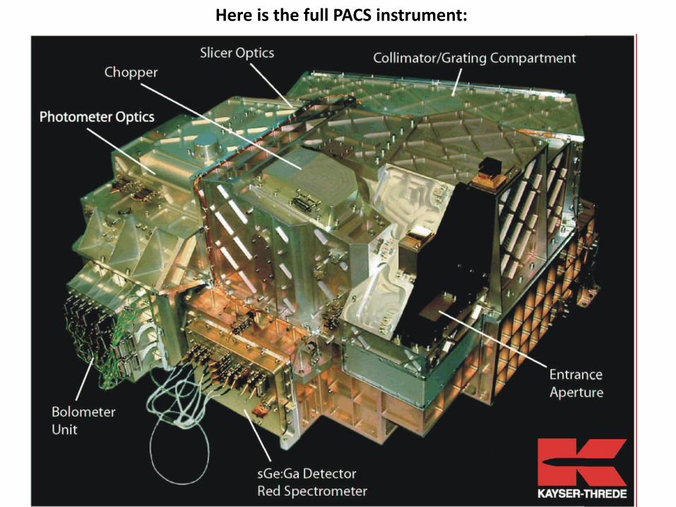
Here is the full PACS instrument:
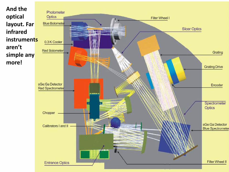
And the optical layout. Far infrared instruments aren’t simple any more!
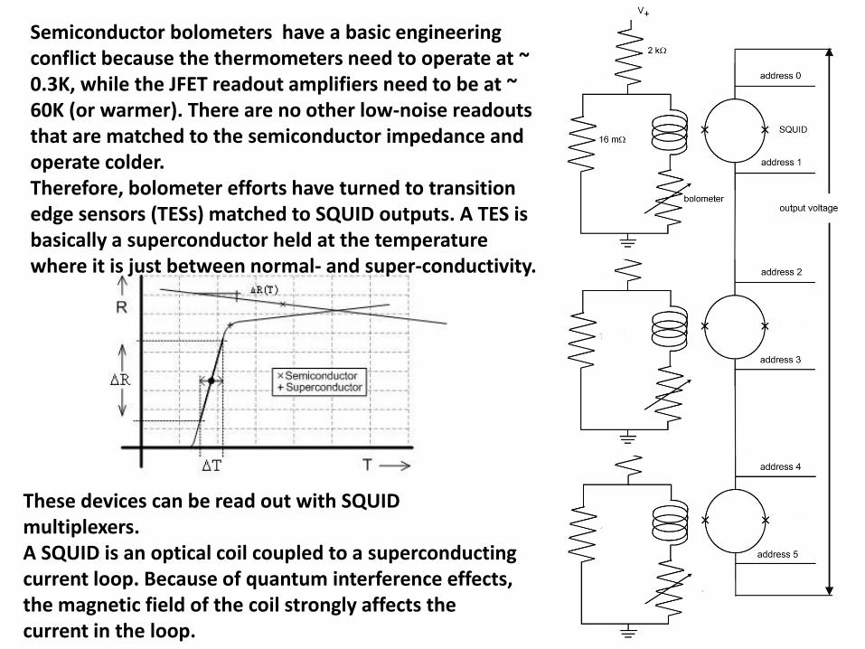
Semiconductor bolometers have a basic engineering conflict because the thermometers need to operate at ~ 0.3K, while the JFET readout amplifiers need to be at ~ 60K (or warmer). There are no other low-noise readouts that are matched to the semiconductor impedance and operate colder. Therefore, bolometer efforts have turned to transition edge sensors (TESs) matched to SQUID outputs. A TES is basically a superconductor held at the temperature where it is just between normal- and super-conductivity.
These devices can be read out with SQUID multiplexers. A SQUID is an optical coil coupled to a superconducting current loop. Because of quantum interference effects, the magnetic field of the coil strongly affects the current in the loop.
Superconductivity
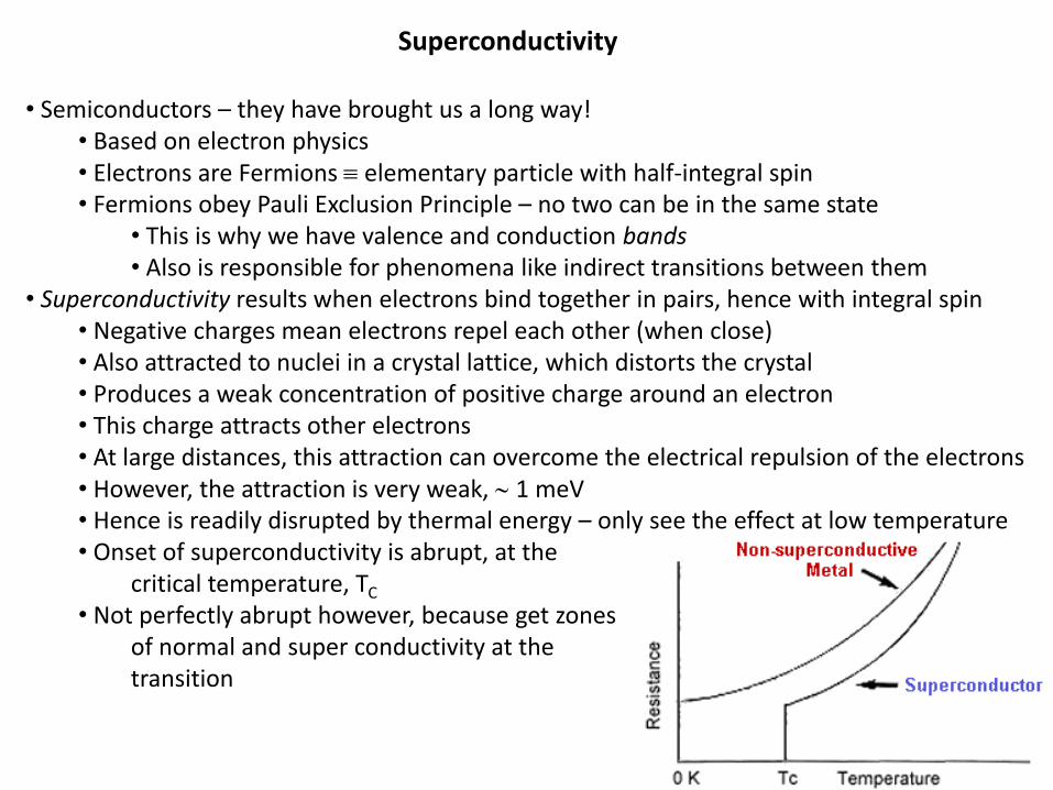
• Semiconductors – they have brought us a long way! • Based on electron physics • Electrons are Fermions elementary particle with half-integral spin • Fermions obey Pauli Exclusion Principle – no two can be in the same state
• This is why we have valence and conduction bands • Also is responsible for phenomena like indirect transitions between them
• Superconductivity results when electrons bind together in pairs, hence with integral spin • Negative charges mean electrons repel each other (when close) • Also attracted to nuclei in a crystal lattice, which distorts the crystal • Produces a weak concentration of positive charge around an electron • This charge attracts other electrons • At large distances, this attraction can overcome the electrical repulsion of the electrons • However, the attraction is very weak, 1 meV • Hence is readily disrupted by thermal energy – only see the effect at low temperature • Onset of superconductivity is abrupt, at the
critical temperature, TC • Not perfectly abrupt however, because get zones of normal and super conductivity at the
transition
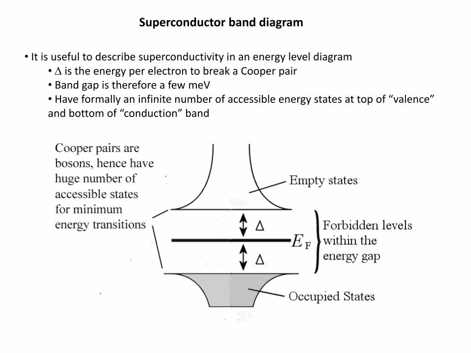
Superconductor band diagram
• It is useful to describe superconductivity in an energy level diagram • is the energy per electron to break a Cooper pair • Band gap is therefore a few meV • Have formally an infinite number of accessible energy states at top of “valence” and bottom of “conduction” band

SCUBA-2 uses superconductivity to provide 10,000 pixels operating simultaneously at 450 and 850 mm.
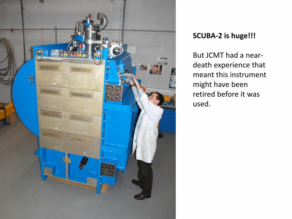
SCUBA-2 is huge!!! But JCMT had a near-death experience that meant this instrument might have been retired before it was used.

Update on JCMT Ownership On 21st June 2013, I issued an Announcement of Opportunity soliciting Expressions of Interest in operating the JCMT as a UH-owned telescope following the planned withdrawal of STFC on 30th September 2014. I am pleased to report that four Expressions of Interest were received: one each from the UK and Canadian communities, one from Purple Mountain Observatory, and one from the East Asian Core Observatories Association (EACOA). EACOA is an affiliation of four astronomical research institutes: ASIAA (Taiwan), NAOC (China), KASI (South Korea) and NAOJ (Japan). EACOA and the UK and Canadian communities have agreed their intention to form a new partnership to operate the JCMT (the interest from Purple Mountain has been subsumed within EACOA). EACOA will be the lead partner. Funding initiatives are underway in the UK and Canada to support the continued participation of those communities. EACOA submitted a full proposal to UH in April. The parties have now embarked on a process that would transfer the legal ownership of the JCMT from STFC to UH, and would set up a scientific cooperation agreement between UH and EACOA. The terms of these agreements are currently being negotiated between the parties and, on the UH side, would require approval by the Board of Regents. The goal is to finalise both of these agreements and complete the transfer of the telescope by 30th September. Professor Gary Davis Director, JCMT 9th June 2014
Microwave Kinetic Inductance Detectors (MKIDs)
Free charged particles are accelerated by any high-frequency electric field; because of conservation of momentum, it takes a finite time for them to react. As a result, they impose a phase lag similar to that created in a conventional electrical circuit by an inductor, an effect described as kinetic inductance. Kinetic inductance is prominent in superconductors because of the high mobility of the Cooper pairs. A MKID is based on this process. The breaking of the Cooper pairs by incident photons (requires of order a meV) creates excess quasi-particles and affects the reactance of the detector to increase the inductance (and the resistance), because the quasi-particles block the Cooper pairs from occupying some of the electron states. If the detector is placed in a resonant circuit, a photon flux that breaks the Cooper pairs can change the resonant frequency. Resonant frequencies of ~ 10 GHz are used, and the resonance can be made sufficiently sharp (high Q) that it is less than 1 MHz wide. Therefore, a large number of these circuits can be connected to a single pair of lines and read out by a high frequency amplifier
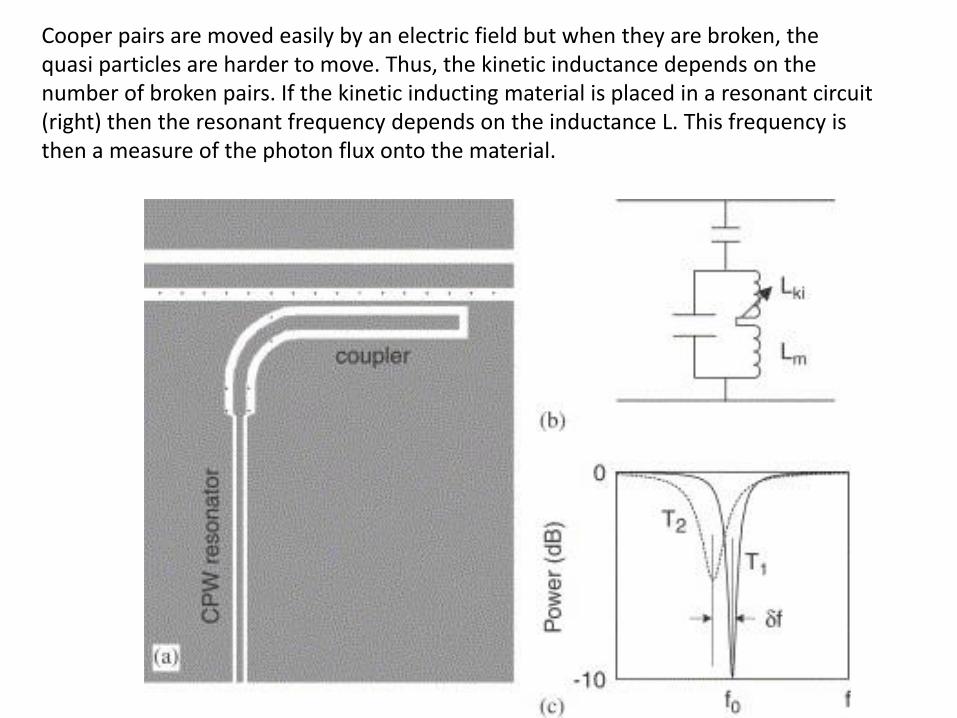
Cooper pairs are moved easily by an electric field but when they are broken, the quasi particles are harder to move. Thus, the kinetic inductance depends on the number of broken pairs. If the kinetic inducting material is placed in a resonant circuit (right) then the resonant frequency depends on the inductance L. This frequency is then a measure of the photon flux onto the material.
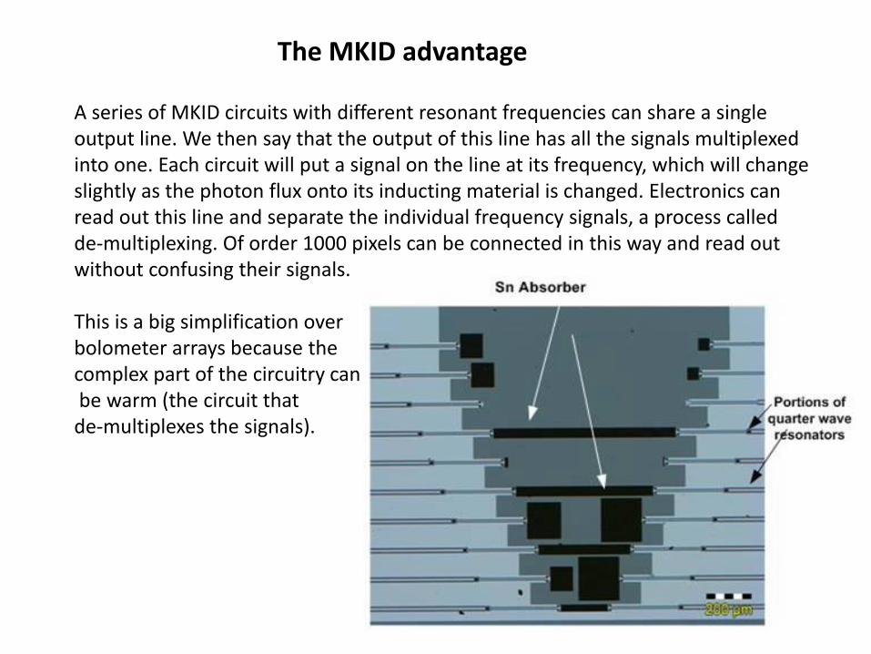
The MKID advantage
A series of MKID circuits with different resonant frequencies can share a single output line. We then say that the output of this line has all the signals multiplexed into one. Each circuit will put a signal on the line at its frequency, which will change slightly as the photon flux onto its inducting material is changed. Electronics can read out this line and separate the individual frequency signals, a process called de-multiplexing. Of order 1000 pixels can be connected in this way and read out without confusing their signals. This is a big simplification over bolometer arrays because the complex part of the circuitry can be warm (the circuit that de-multiplexes the signals).
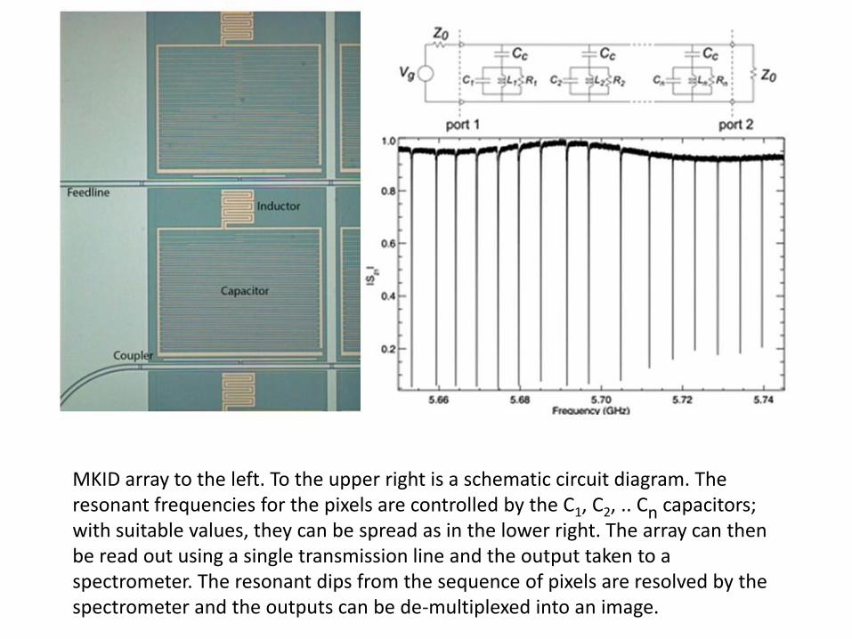
MKID array to the left. To the upper right is a schematic circuit diagram. The resonant frequencies for the pixels are controlled by the C1, C2, .. Cn capacitors; with suitable values, they can be spread as in the lower right. The array can then be read out using a single transmission line and the output taken to a spectrometer. The resonant dips from the sequence of pixels are resolved by the spectrometer and the outputs can be de-multiplexed into an image.

A comparison: •TES-based bolometer arrays can be made (with significant difficulty) in arrays of about 1000 pixels. SCUBA2 has four 32 X 40 pixel arrays per band as an example.
NEPs can be below 10-18 W/Hz1/2 but require very low temperatures (0.3K)
Significant infrastructure required to achieve this performance
• MKIDs are currently made in arrays of similar size but promise to provide larger ones
Best NEPs are about 3 X 10-18 W/Hz1/2 and temperatures need to be low but not sub-1-Kelvin Greatly reduced infrastructure Well matched to groundbased telescopes

Now for something different: heterodyne receivers. Here is a block diagram. The astronomical signal is combined with a locally generated signal of almost the same frequency (from the local oscillator). The combined signal goes to a mixer, and the output is modulated at the intermediate frequency (IF) by the interference of the two. The IF is amplified and taken to a “detector” stage that smooths it for easier
interpretation.
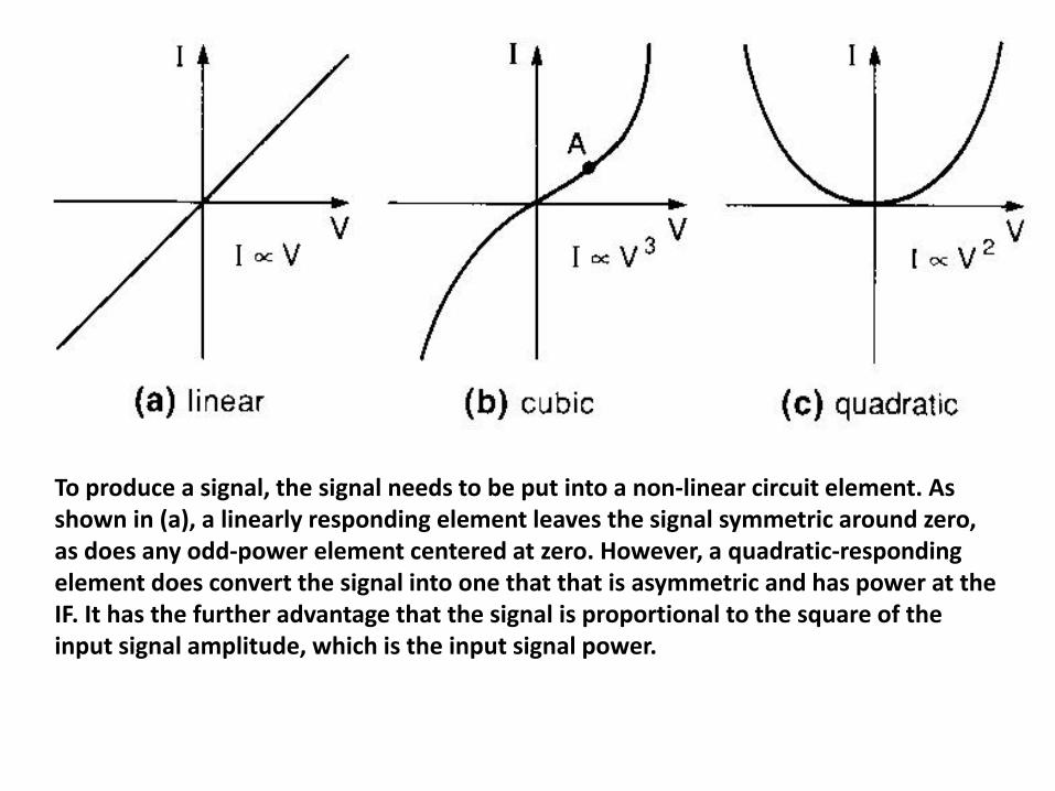
To produce a signal, the signal needs to be put into a non-linear circuit element. As shown in (a), a linearly responding element leaves the signal symmetric around zero, as does any odd-power element centered at zero. However, a quadratic-responding element does convert the signal into one that that is asymmetric and has power at the IF. It has the further advantage that the signal is proportional to the square of the input signal amplitude, which is the input signal power.

Here is the interference process between one input in a thin solid line and another in a thin dashed line. The resulting signal (heavy line) has a component
at the difference frequency. We say it has been down-converted to the IF.
In principle, the IF signal can be amplified with a strong local oscillator, but often the down-conversion is used just to get a signal where better electronics are available.
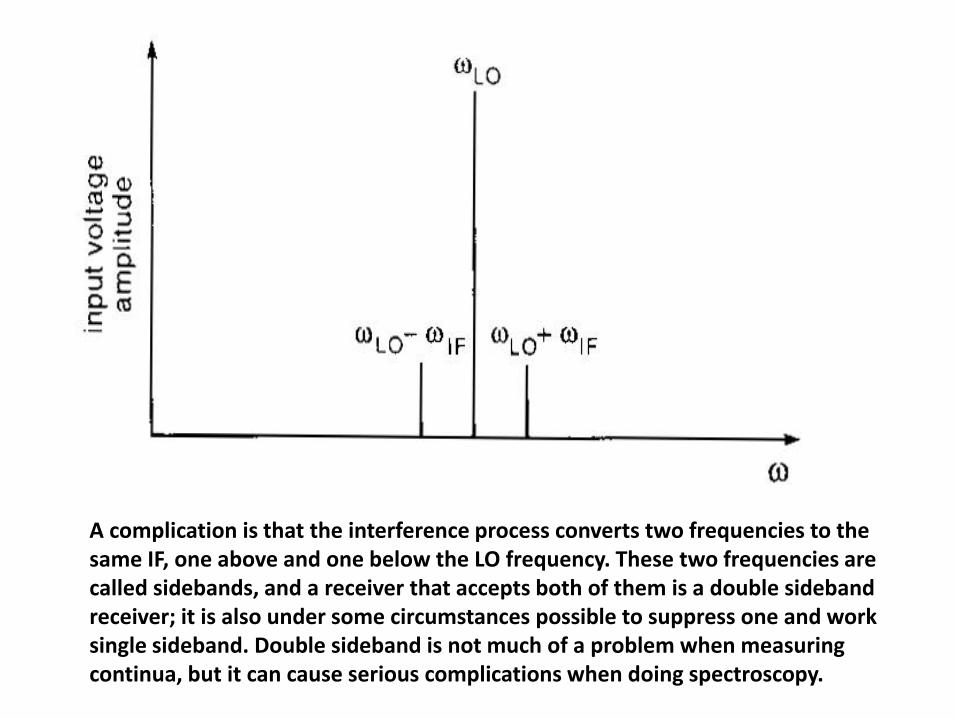
A complication is that the interference process converts two frequencies to the same IF, one above and one below the LO frequency. These two frequencies are called sidebands, and a receiver that accepts both of them is a double sideband receiver; it is also under some circumstances possible to suppress one and work single sideband. Double sideband is not much of a problem when measuring continua, but it can cause serious complications when doing spectroscopy.

The final stage in the signal processing is called the detector. It rectifies and smooths the IF signal to produce a slowly varying output that again is proportional to the input power. This signal can be taken to an analog to digital converter and then in digital form into a computer for further processing.

Some restrictions on the operation of a receiver: Etendue must be preserved through the system. Therefore, the photons approach the mixer over a range of angles. To maintain coherence, they must lie within )4(,
D
That is, the receiver must work at the diffraction limit of the telescope. In addition, only one polarization can be interfered with the LO, so they only work for a single polarization. Taken together these two requirements are called the “antenna theorem.” In addition, because the output retains information about the phase of the input photons, the detection is subject to the Heisenberg Uncertainty Principle:
)5(4/ htE
This translates into the “quantum limit,” which is the fundamental noise limit for all heterodyne receivers:
)6(k
hTN
The noise temperature, TN, is the temperature of a blackbody that, if placed over the entrance to the receiver, would give signal to noise of unity (somewhat analogous to NEP).
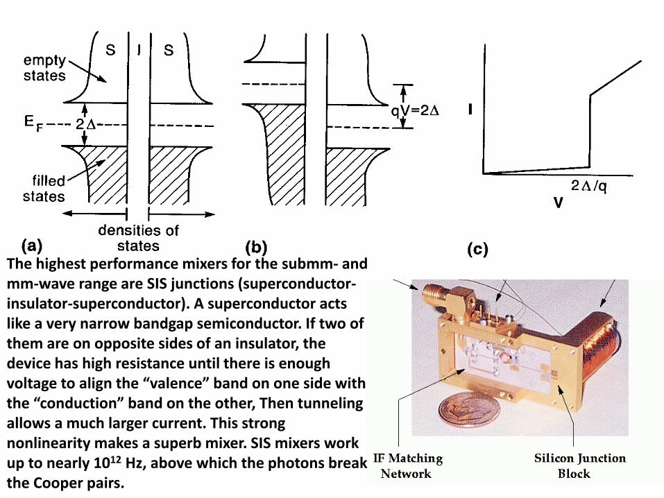
The highest performance mixers for the submm- and mm-wave range are SIS junctions (superconductor-insulator-superconductor). A superconductor acts like a very narrow bandgap semiconductor. If two of them are on opposite sides of an insulator, the device has high resistance until there is enough voltage to align the “valence” band on one side with the “conduction” band on the other, Then tunneling allows a much larger current. This strong nonlinearity makes a superb mixer. SIS mixers work up to nearly 1012 Hz, above which the photons break the Cooper pairs.
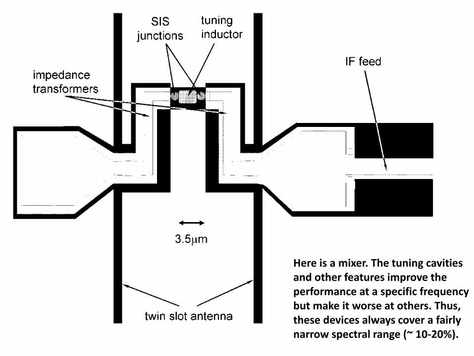
Here is a mixer. The tuning cavities and other features improve the performance at a specific frequency but make it worse at others. Thus, these devices always cover a fairly narrow spectral range (~ 10-20%).

Sideband separating receivers: Two mixers driven by LO signals that have a 90o phase difference can isolate one of the sidebands. If the upper and lower sideband signals are exactly in phase for one of the mixers, they will be exactly at opposite phase for the other. Circuitry can combine these two signals so either the upper or lower sideband is canceled; generally, there are two outputs, one with the lower and the other with the upper sideband. The dashed line is the mixer output for the lower sideband and the solid line is for the upper sideband. The LO is shifted by 90o between the upper and lower panel.

Submillimeter Observatories
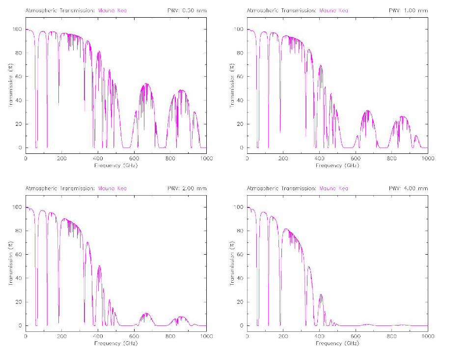
The driving requirement is that they have very little water vapor above them
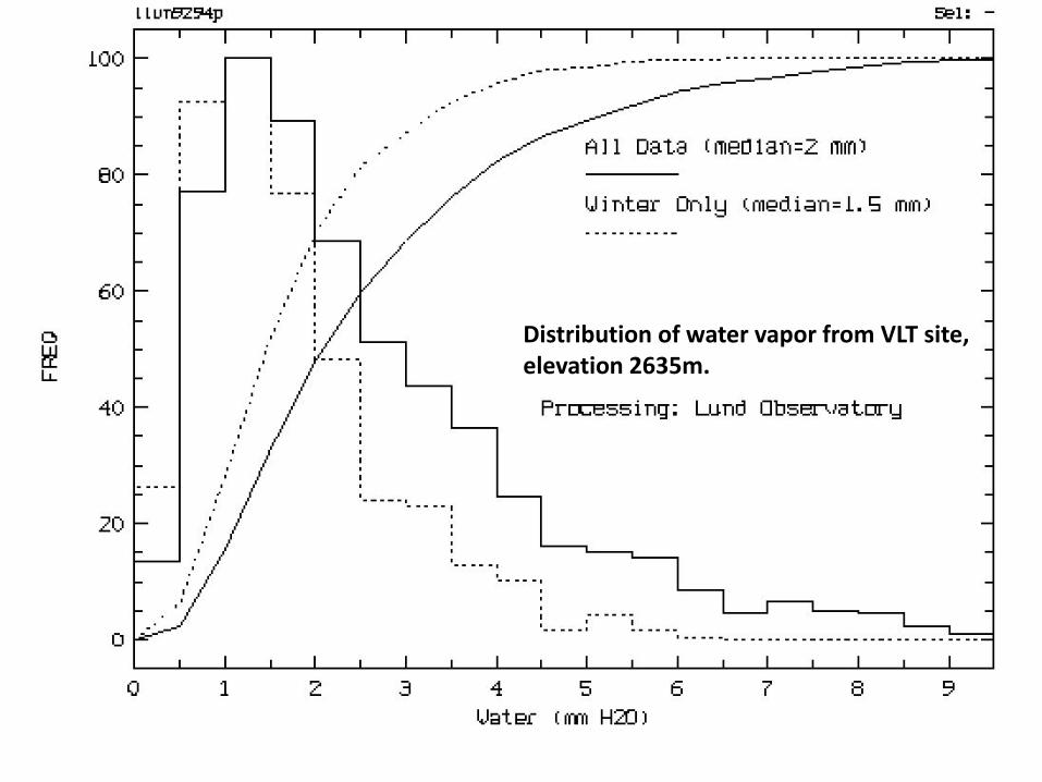
Distribution of water vapor from VLT site, elevation 2635m.
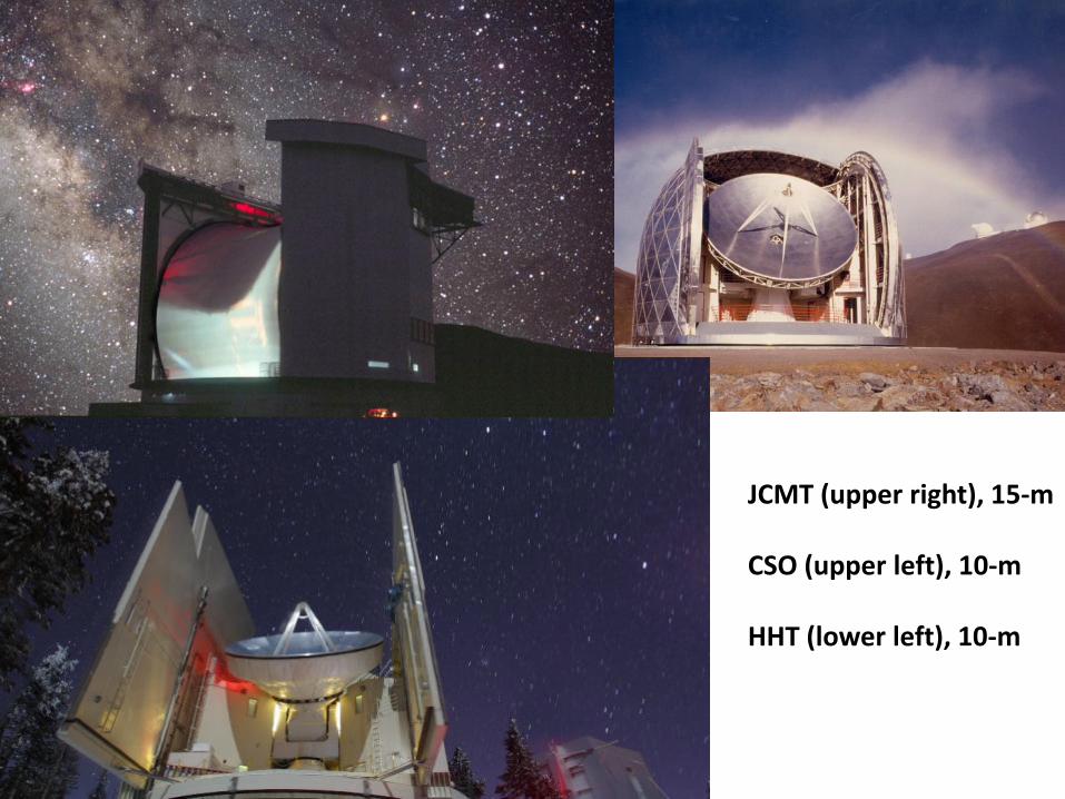
JCMT (upper right), 15-m CSO (upper left), 10-m HHT (lower left), 10-m
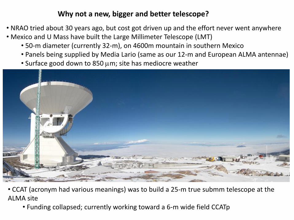
Why not a new, bigger and better telescope?
• NRAO tried about 30 years ago, but cost got driven up and the effort never went anywhere • Mexico and U Mass have built the Large Millimeter Telescope (LMT)
• 50-m diameter (currently 32-m), on 4600m mountain in southern Mexico • Panels being supplied by Media Lario (same as our 12-m and European ALMA antennae) • Surface good down to 850 mm; site has mediocre weather
• CCAT (acronym had various meanings) was to build a 25-m true submm telescope at the ALMA site
• Funding collapsed; currently working toward a 6-m wide field CCATp
Related Documents