Welcome message from author
This document is posted to help you gain knowledge. Please leave a comment to let me know what you think about it! Share it to your friends and learn new things together.
Transcript


www.passivecomponent.com
Subject Page
Metal Oxide Varistor (MOV) . . . . . . . . . . . . . . . . . . . . . . . . . . . . . . . . . . . . . . . . . . . . . . . . . . . . 1
Varistors-5D Series . . . . . . . . . . . . . . . . . . . . . . . . . . . . . . . . . . . . . . . . . . . . . . . . . . . . . . . . . . 3
Varistors-7D Series . . . . . . . . . . . . . . . . . . . . . . . . . . . . . . . . . . . . . . . . . . . . . . . . . . . . . . . . . . 4
Varistors-10D Series . . . . . . . . . . . . . . . . . . . . . . . . . . . . . . . . . . . . . . . . . . . . . . . . . . . . . . . . . 5
Varistors-14D Series . . . . . . . . . . . . . . . . . . . . . . . . . . . . . . . . . . . . . . . . . . . . . . . . . . . . . . . . . 6
Varistors-20D Series . . . . . . . . . . . . . . . . . . . . . . . . . . . . . . . . . . . . . . . . . . . . . . . . . . . . . . . . . 7
Varistors-25D Series . . . . . . . . . . . . . . . . . . . . . . . . . . . . . . . . . . . . . . . . . . . . . . . . . . . . . . . . . 8
Varistors-5E、7E Series. . . . . . . . . . . . . . . . . . . . . . . . . . . . . . . . . . . . . . . . . . . . . . . . . . . . . . . 9
Varistors-10E、14E Series. . . . . . . . . . . . . . . . . . . . . . . . . . . . . . . . . . . . . . . . . . . . . . . . . . . . 10
Varistors-18E、20E Series. . . . . . . . . . . . . . . . . . . . . . . . . . . . . . . . . . . . . . . . . . . . . . . . . . . . 11
V-I Curve . . . . . . . . . . . . . . . . . . . . . . . . . . . . . . . . . . . . . . . . . . . . . . . . . . . . . . . . . . . . . . . . . . 12
Packing Specification (5Ø - 25Ø Series) . . . . . . . . . . . . . . . . . . . . . . . . . . . . . . . . . . . . . . . . 15
Taping Specifications - 5Ø and 7Ø . . . . . . . . . . . . . . . . . . . . . . . . . . . . . . . . . . . . . . . . . . . . . 16
Taping Specifications - 10Ø and 14Ø . . . . . . . . . . . . . . . . . . . . . . . . . . . . . . . . . . . . . . . . . . . 17
Taping Specifications - 18Ø and 20Ø . . . . . . . . . . . . . . . . . . . . . . . . . . . . . . . . . . . . . . . . . . . 18
Big Size Varistor - 32D Series . . . . . . . . . . . . . . . . . . . . . . . . . . . . . . . . . . . . . . . . . . . . . . . . . 19
Big Size Varistor - 34mm Single Series . . . . . . . . . . . . . . . . . . . . . . . . . . . . . . . . . . . . . . . . . 20
Big Size Varistor - 34mm Dual Series. . . . . . . . . . . . . . . . . . . . . . . . . . . . . . . . . . . . . . . . . . . 21
Big Size Varistor - 40D Series . . . . . . . . . . . . . . . . . . . . . . . . . . . . . . . . . . . . . . . . . . . . . . . . . 22
Big Size Varistor - 53D Series . . . . . . . . . . . . . . . . . . . . . . . . . . . . . . . . . . . . . . . . . . . . . . . . . 23
V-I Curve . . . . . . . . . . . . . . . . . . . . . . . . . . . . . . . . . . . . . . . . . . . . . . . . . . . . . . . . . . . . . . . . . . 25
Table of Contents

www.passivecomponent.com
2
Metal Oxide Varistor (MOV)
■HOW TO ORDER
SR 241 K 10 D S 40 X
Type code
SR:Walsin Varistor
Varistor Voltage
(DC volt)(From 180 to 112)Two significant digitsFollowed by no. ofzeros180=18volt101=100volt102=1000volt
Tolerance
J:+/-5%K:+/-10%
Disk Size Code
05 : 5mm07 : 7mm10 : 10mm14 : 14mm18 : 18mm20 : 20mm25 : 25mm
Disk Type
D : Standard disk type
E : High energy disk type
Lead Type or Taping Code
For bulk packing: S : Straight Lead L : Inline CrimpedO : Outward Crimped I : Inward Crimped
T**: Taping CodePlease refer to page 15~18 for taping details.
Lead Cutting
Lead Cutting for Bulk Packing:40=4.0±1.0mm65=6.5±1.0mmP1=11±1.0mmNo code ≥ 25mm
Special Request
Special lead cutting tolerance Special lead spacing (Please see below)
Special varistor voltage range...etc
* If customers have no special request on lead shape, we provide straight lead for voltage type ≤ 471K and in-line crimped lead for voltage type ≥ 511K.
■VARISTOR SPECIAL REQUEST
F: 0.5mm lead length tolerance for short lead cutting (exclude straight lead)X: 7.5mm lead spacing for 20D and 20E (lead wire is 0.8mm diameter)Z: 5mm lead spacing for 10D(E), 14D(E)H: Special request
■VARISTOR PART NUMBER EXAMPLES :
Ex.1. SR241K07DT14: 7mm, 241K, inward crimped lead and reel taped.
Ex.2. SR361K10DI45: 10mm, 361K, bulk packing, inward crimped lead, lead cutting length 4.5 ±1.0mm
Ex.3. SR621K20EOP2: 20mm, 621K, high energy, bulk, outward crimped lead, lead spacing 12mm±1.0mm.
Ex.4. SR271K20DO65X: 20mm, 271K, bulk, outward crimped lead, lead spacing 7.5 mm, lead cutting 6.5 ± 1.0mm
Ex.5. SR241K10DS40F: 10mm, 241K, bulk, straight lead, lead cutting 4.0 ± 0.5mm.
■DIMENSIONS QUICK REFERENCE : If specific item’s dimensions, please contact sales
Series 5D,5E 7D,7E 10D,10E 14D,14E 18E 20D,20E 25D
Dmax 7.0 9.5 14.0 17.5 21.0 24.0 28.5
d* 0.6 0.6 0.8 0.8 0.8 1.0 1.0
W** 5.0 5.0 7.5 7.5 7.5 10.0 12.7
Hmax 12.5 14.5 20.0 22.5 27.5 29.5 36.5
H1max 10.0 12.0 17.0 20.5 24.0 28.0 34.0
Tmax 4.9 4.9 8.5 8.5 9.0 9.0 9.5
* ±0.02 ** ±1.0 (Unit: mm)
Inward Crimped Straight Lead
Outward Crimped Inline Crimped
Remark:The lead length (L) is 25mm minimum unless requested by customers; please refer to lead cutting code in “How to Order”.
1
1

www.passivecomponent.com
3
Metal Oxide Varistor (MOV)
■CHARACTERISTICS
High performance transient voltage suppression Short response time to surge voltage Low standby power dissipation Excellent clamping characteristics High performance withstanding surge currents High reliability UL, CSA, VDE and CQC recognized
■APPLICATIONS
Surge protection in: Consumer electronics Industrial electronics Communication electronics Measuring and controlling systems Electronic home appliances Protection against surges induced by lighting striking incoming
power lines. Suppression of surges caused by switching inductive loads such
as transformers, relays and coils. Protection of rectification diodes, SCRs, power transistors,
semiconductor devices, etc.
■DEFINITION OF VARISTOR TERMS
Rated RMS Voltage, Rated DC Voltage : The maximum designated values of power system voltage
that may be applied continuously between the terminals of a device.
Varistor Voltage : Test characteristic that is used to classify varistors by type. A test current of 1mA DC is typically used to determine
varistor voltage classification type. Varistor voltage clamping characteristics can be defined at various test levels.
Rated Peak Single Pulse Transient Current : Maximum surge current, 8/20 µs waveform which a varistor is
rated to withstand for a single surge. Rated Single Pulse Transient Energy : Maximum allowable energy for a single impulse (see specified
waveforms). Maximum Clamping Voltage : Measured peak voltage across the device terminals when
a current impulse of specified amplitude and waveform is conducted through the varistor.
Typical Capacitance : Typical capacitance values are measured at a test frequency
of 1kHz. Capacitance values are only for reference purpose only, not subject to outgoing inspection.
■GENERAL CHARACTERISTICS
Storage Temperature : –55˚C to +125˚C Operating Surface Temperature : 125˚C Operating Ambient Temperature : –55˚C to +85˚C (without
derating) Maximum Voltage-Temperature Coefficient : < –0.05% / ˚C Insulation Resistance : 1000 Mega-ohm minimum Hi Pot (Leads To Case, 1 Min.) : 2500 VDC Typical Response Time : <15 Nero-seconds Epoxy Rating : 94V-0 Current / Energy Derating (>85˚C ) : –2.5% / ˚C DC Leakage Current : 200µA maximum (at rated DC working
voltage ) Solderability : MIL-STD-202F Power Dissipation Ratings(P, in-watts) : Disc Size 11Vac~40Vac 50Vac~680Vac 5mm 0.01 0.15 7mm 0.02 0.25 10mm 0.05 0.4 14mm 0.1 0.6 18mm — 0.8 20mm 0.2 1.0 25mm — 1.2 32mm — 1.6 34mm(single) — 2.1 34mm(dual) — 2.73 40mm — 2.1 53mm — 2.5 All definitions are according to IEEE specifications C62.33.
■ENERGY DERATING VERSUS TEMPERATURE ■PEAK CURRENT PER PULSE VERSUS PULSE DURATION
Number of Pulses on Order From 100 % Respectively :
1 Pulse10 Pulses102 Pulses103 Pulses104 Pulses105 Pulses106 Pulses
2

www.passivecomponent.com
4
Part Number
Maximum Allowable Voltage
Varistor Voltage
WithstandingSurge Current
(8/20 µs)
Max. Clamping Voltage (8/20 µs)
Maximum Engergy
Typical Capacitance Safety
ApprovalACrms DC DC Volts 1 time Vc Ip 2ms 10/1000µs @1kHz
Volts Volts Min Max Amps Volts Amps Joules PF
SR 180K05D □□ 11 14 16 20 100 36 1 0.4 0.6 1500 ○△ ◇
SR 220K05D □□ 14 18 20 24 100 43 1 0.6 0.8 1260 ○△ ◇
SR 270K05D □□ 17 22 24 30 100 53 1 0.7 0.9 1050 ○△ ◇
SR 330K05D □□ 20 26 30 36 100 65 1 0.9 1.2 850 ○△ ◇
SR 390K05D □□ 25 31 35 43 100 77 1 1.1 1.3 600 ○△ ◇
SR 470K05D □□ 30 38 42 52 100 93 1 1.4 1.6 500 ○△ ◇
SR 560K05D □□ 35 45 50 62 100 110 1 1.5 1.9 400 ○△ ◇
SR 680K05D □□ 40 56 61 75 100 135 1 1.8 2.3 360 ○△ ◇
SR 820K05D □□ 50 66 74 90 400 135 5 2.4 3.0 350 ○△ ◇
SR 101K05D □□ 60 85 90 110 400 165 5 2.4 3.5 320 ○△ ◇
SR 121K05D □□ 75 102 108 132 400 200 5 3.0 5.0 250 ○△ ◇
SR 151K05D □□ 95 127 135 165 400 250 5 3.5 5.5 180 ○△ ◇
SR 181K05D □□ 120 160 170 207 400 320 5 4.2 8.0 155 ○△ ☆◇
SR 201K05D □□ 130 175 185 225 400 340 5 5.0 8.5 140 ○△□☆◇
SR 221K05D □□ 140 180 198 242 400 360 5 6.0 9.0 125 ○△□☆◇
SR 241K05D □□ 150 200 216 264 400 395 5 6.5 10.0 115 ○△□☆◇
SR 271K05D □□ 180 230 255 311 400 475 5 7.5 11.0 105 ○△□☆◇
SR 301K05D □□ 195 250 270 330 400 525 5 8.0 11.5 95 ○△□☆◇
SR 331K05D □□ 210 275 297 363 400 540 5 8.5 11.7 85 ○△□☆◇
SR 361K05D □□ 230 300 324 396 400 595 5 9.0 13.0 80 ○△□☆◇
SR 391K05D □□ 250 330 351 429 400 650 5 10 15 75 ○△□☆◇
SR 431K05D □□ 275 370 387 473 400 710 5 11 16 65 ○△□☆◇
SR 471K05D □□ 300 385 423 517 400 775 5 13 19 55 ○△□☆◇
SR 511K05D □□ 320 420 459 561 400 865 5 15 21 39 ○△□
SR 561K05D □□ 360 470 522 638 400 960 5 17 25 36 ○△□☆
SR 621K05D □□ 390 505 558 682 400 1040 5 19 27 33 ○△□☆
SR 681K05D □□ 420 560 612 748 400 1120 5 21 30 30 ○△□☆
Varistors - 5D Series
Remark :1. □□ : Suffix adding; please refer “How to Order” for details.2. All parts approved as follows:(1) ○ : UL 1449 recognized (File # E172311). (2) △ : UL 497B recognized (File # E199593). (3) □ : UL 1414 recognized (File # E182369). (4) ☆ : CSA 22.2 #1 certified (File # LR109496-1 and LR109496-4). (5) ◇ : VDE/CECC 42000/42200/42201, IEC 61051-1/61051-2/61051-2-2 (Certificate # 5932, 40010090, 40003435).(6) CQC recognized for all part numbers (CQC04001010926).
3

www.passivecomponent.com
5
Varistors - 7D Series
Part Number
Maximum Allowable Voltage
Varistor Voltage
WithstandingSurge Current
(8/20 µs)
Max. Clamping Voltage (8/20 µs)
Maximum Engergy
Typical Capacitance Safety
ApprovalACrms DC DC Volts 1 time Vc Ip 2ms 10/1000µs @1kHz
Volts Volts Min Max Amps Volts Amps Joules PF
SR 180K07D □□ 11 14 16 20 250 36 2.5 0.8 1.0 2900 ○△ ◇
SR 220K07D □□ 14 18 20 24 250 43 2.5 0.9 1.3 2400 ○△ ◇
SR 270K07D □□ 17 22 24 30 250 53 2.5 1.0 1.4 1800 ○△ ◇
SR 330K07D □□ 20 26 30 36 250 65 2.5 1.2 1.7 1500 ○△ ◇
SR 390K07D □□ 25 31 35 43 250 77 2.5 1.5 2.1 1230 ○△ ◇
SR 470K07D □□ 30 38 42 52 250 93 2.5 1.8 2.5 950 ○△ ◇
SR 560K07D □□ 35 45 50 62 250 110 2.5 2.2 3.1 890 ○△ ◇
SR 680K07D □□ 40 56 61 75 250 135 2.5 2.5 3.8 850 ○△ ◇
SR 820K07D □□ 50 66 74 90 1200 135 10 3.5 5.5 830 ○△ ◇
SR 101K07D □□ 60 85 90 110 1200 165 10 4.0 6.5 730 ○△ ◇
SR 121K07D □□ 75 102 108 132 1200 200 10 5.0 7.8 570 ○△ ◇
SR 151K07D □□ 95 127 135 165 1200 250 10 6.5 9.7 400 ○△ ◇
SR 181K07D □□ 120 160 170 207 1200 300 10 8.8 12.0 305 ○△ ☆◇
SR 201K07D □□ 130 175 185 225 1200 340 10 10.0 13.0 275 ○△□☆◇
SR 221K07D □□ 140 180 198 242 1200 360 10 11.0 14.0 250 ○△□☆◇
SR 241K07D □□ 150 200 216 264 1200 395 10 11.0 16.0 230 ○△□☆◇
SR 271K07D □□ 180 230 255 311 1200 455 10 12.0 18.0 205 ○△□☆◇
SR 301K07D □□ 195 250 270 330 1200 505 10 13.0 19.0 185 ○△□☆◇
SR 331K07D □□ 210 275 297 363 1200 540 10 14.0 20.0 170 ○△□☆◇
SR 361K07D □□ 230 300 324 396 1200 595 10 15.0 25.0 155 ○△□☆◇
SR 391K07D □□ 250 330 351 429 1200 650 10 17.0 26.0 145 ○△□☆◇
SR 431K07D □□ 275 370 387 473 1200 710 10 20.0 28.0 130 ○△□☆◇
SR 471K07D □□ 300 385 423 517 1200 775 10 21.0 30.0 115 ○△□☆◇
SR 511K07D □□ 320 420 459 561 1200 850 10 23.0 32.0 88 ○△□☆◇
SR 561K07D □□ 360 470 522 638 1200 960 10 27.0 39.0 85 ○△□☆◇
SR 621K07D □□ 390 505 558 682 1200 1040 10 29.0 43.0 82 ○△□☆◇
SR 681K07D □□ 420 560 612 748 1200 1120 10 32.0 45.0 78 ○△□☆◇
Remark :1. □□ : Suffix adding; please refer “How to Order” for details.2. All parts approved as follows:(1) ○ : UL 1449 recognized (File # E172311). (2) △ : UL 497B recognized (File # E199593). (3) □ : UL 1414 recognized (File # E182369). (4) ☆ : CSA 22.2 #1 certified (File # LR109496-1 and LR109496-4). (5) ◇ : VDE/CECC 42000/42200/42201, IEC 61051-1/61051-2/61051-2-2 (Certificate # 5932, 40010090, 40003435).(6) CQC recognized for all part numbers (CQC04001010927).
4

www.passivecomponent.com
6
Part Number
Maximum Allowable Voltage
Varistor Voltage
WithstandingSurge Current
(8/20 µs)
Max. Clamping Voltage (8/20 µs)
Maximum Engergy
Typical Capacitance Safety
ApprovalACrms DC DC Volts 1 time Vc Ip 2ms 10/1000µs @1kHz
Volts Volts Min Max Amps Volts Amps Joules PF
SR 180K10D □□ 11 14 16 20 500 36 5 1.5 2.1 6000 ○△ ◇
SR 220K10D □□ 14 18 20 24 500 43 5 2.0 2.5 5000 ○△ ◇
SR 270K10D □□ 17 22 24 30 500 53 5 2.5 3.0 4000 ○△ ◇
SR 330K10D □□ 20 26 30 36 500 65 5 3.0 4.0 3500 ○△ ◇
SR 390K10D □□ 25 31 35 43 500 77 5 3.5 4.6 3100 ○△ ◇
SR 470K10D □□ 30 38 42 52 500 93 5 4.5 5.5 2800 ○△ ◇
SR 560K10D □□ 35 45 50 62 500 110 5 5.5 7.0 2400 ○△ ◇
SR 680K10D □□ 40 56 61 75 500 135 5 6.5 8.2 2100 ○△ ◇
SR 820K10D □□ 50 66 74 90 2500 135 25 8.0 12.0 1600 ○△ ◇
SR 101K10D □□ 60 85 90 110 2500 165 25 10.0 15.0 1400 ○△ ◇
SR 121K10D □□ 75 102 108 132 2500 200 25 12.0 18.0 1200 ○△ ◇
SR 151K10D □□ 95 127 135 165 2500 250 25 16.0 22.0 1100 ○△ ◇
SR 181K10D □□ 120 160 170 207 2500 300 25 18.5 27.5 700 ○△ ☆◇
SR 201K10D □□ 130 175 185 225 2500 340 25 20.0 30.0 640 ○△□☆◇
SR 221K10D □□ 140 180 198 242 2500 360 25 23.0 32.0 600 ○△□☆◇
SR 241K10D □□ 150 200 216 264 2500 395 25 25.0 35.0 560 ○△□☆◇
SR 271K10D □□ 180 230 255 311 2500 455 25 30.0 40.0 500 ○△□☆◇
SR 301K10D □□ 195 250 270 330 2500 505 25 32.0 42.5 450 ○△□☆◇
SR 331K10D □□ 210 275 297 363 2500 540 25 33.5 44.5 415 ○△□☆◇
SR 361K10D □□ 230 300 324 396 2500 595 25 35.0 47.0 380 ○△□☆◇
SR 391K10D □□ 250 330 351 429 2500 650 25 40.0 60.0 350 ○△□☆◇
SR 431K10D □□ 275 370 387 473 2500 710 25 45.0 65.0 310 ○△□☆◇
SR 471K10D □□ 300 385 423 517 2500 775 25 46.0 70.0 280 ○△□☆◇
SR 511K10D □□ 320 420 459 561 2500 840 25 47.0 71.0 260 ○△□☆◇
SR 561K10D □□ 360 470 522 638 2500 910 25 48.0 72.0 240 ○△□☆◇
SR 621K10D □□ 390 505 558 682 2500 1025 25 49.0 73.0 150 ○△□☆◇
SR 681K10D □□ 420 560 612 748 2500 1120 25 50.0 74.0 130 ○△□☆◇
SR 751K10D □□ 460 615 675 825 2500 1240 25 51.0 75.0 120 ○△□☆◇
SR 781K10D □□ 485 640 702 858 2500 1290 25 52.0 80.0 120 ○△□☆◇
SR 821K10D □□ 510 675 738 902 2500 1350 25 55.0 85.0 110 ○△□☆◇
SR 911K10D □□ 550 745 819 1001 2500 1400 25 60.0 93.0 90 ○ □☆◇
SR 102K10D □□ 625 825 900 1100 2500 1650 25 65.0 102 80 ○ □☆◇
SR 112K10D □□ 680 895 962 1175 2500 1815 25 70.0 115 70 ○ □☆◇
Varistors - 10D Series
Remark :1. □□ : Suffix adding; please refer “How to Order” for details.2. All parts approved as follows:(1) ○ : UL 1449 recognized (File # E172311). (2) △ : UL 497B recognized (File # E199593). (3) □ : UL 1414 recognized (File # E182369). (4) ☆ : CSA 22.2 #1 certified (File # LR109496-1 and LR109496-4). (5) ◇ : VDE/CECC 42000/42200/42201, IEC 61051-1/61051-2/61051-2-2 (Certificate # 5932, 40010090, 40003435).(6) CQC recognized for all part numbers (CQC04001010928).
5
www.passivecomponent.com
7
Varistors - 14D Series
Part Number
Maximum Allowable Voltage
Varistor Voltage
WithstandingSurge Current
(8/20 µs)
Max. Clamping Voltage (8/20 µs)
Maximum Engergy
Typical Capacitance Safety
ApprovalACrms DC DC Volts 1 time Vc Ip 2ms 10/1000µs @1kHz
Volts Volts Min Max Amps Volts Amps Joules PF
SR 180K14D □□ 11 14 16 20 1000 36 10 3.5 4.0 15000 ○△ ◇
SR 220K14D □□ 14 18 20 24 1000 43 10 4.0 5.0 12000 ○△ ◇
SR 270K14D □□ 17 22 24 30 1000 53 10 5.0 6.0 8500 ○△ ◇
SR 330K14D □□ 20 26 30 36 1000 65 10 6.0 7.5 7200 ○△ ◇
SR 390K14D □□ 25 31 35 43 1000 77 10 7.0 8.6 6300 ○△ ◇
SR 470K14D □□ 30 38 42 52 1000 93 10 8.5 10.0 5500 ○△ ◇
SR 560K14D □□ 35 45 50 62 1000 110 10 10.0 11.0 4800 ○△ ◇
SR 680K14D □□ 40 56 61 75 1000 135 10 12.0 14.0 4000 ○△ ◇
SR 820K14D □□ 50 66 74 90 4500 135 50 15.0 22.0 3300 ○△ ◇
SR 101K14D □□ 60 85 90 110 4500 165 50 20.0 30.0 2900 ○△ ◇
SR 121K14D □□ 75 102 108 132 4500 200 50 22.0 34.0 2600 ○ ◇
SR 151K14D □□ 95 127 135 165 4500 250 50 30.0 45.0 2000 ○△ ◇
SR 181K14D □□ 120 160 170 207 4500 300 50 33 53.0 1400 ○△ ☆◇
SR 201K14D □□ 130 175 185 225 4500 340 50 38 60.0 1370 ○△□☆◇
SR 221K14D □□ 140 180 198 242 4500 360 50 40 60.0 1150 ○△□☆◇
SR 241K14D □□ 150 200 216 264 4500 395 50 45 66.0 1060 ○△□☆◇
SR 271K14D □□ 180 230 255 311 4500 455 50 52 72.0 950 ○△□☆◇
SR 301K14D □□ 195 250 270 330 4500 505 50 56 78.0 890 ○△□☆◇
SR 331K14D □□ 210 275 297 363 4500 545 50 63 87.0 800 ○△□☆◇
SR 361K14D □□ 230 300 324 396 4500 595 50 70 98.0 725 ○△□☆◇
SR 391K14D □□ 250 330 351 429 4500 650 50 72 102 665 ○△□☆◇
SR 431K14D □□ 275 370 387 473 4500 710 50 75 115 600 ○△□☆◇
SR 471K14D □□ 300 385 423 517 4500 775 50 80 125 570 ○△□☆◇
SR 511K14D □□ 320 420 459 561 4500 840 50 82 128 530 ○△□☆◇
SR 561K14D □□ 360 470 522 638 4500 910 50 85 139 480 ○△□☆◇
SR 621K14D □□ 390 505 558 682 4500 1025 50 88 142 270 ○△□☆◇
SR 681K14D □□ 420 560 612 748 4500 1120 50 90 142 240 ○△□☆◇
SR 751K14D □□ 460 615 675 825 4500 1240 50 100 143 210 ○△□☆◇
SR 781K14D □□ 485 640 702 858 4500 1290 50 105 148 205 ○△□☆◇
SR 821K14D □□ 510 675 738 902 4500 1350 50 110 157 200 ○△□☆◇
SR 911K14D □□ 550 745 819 1001 4500 1400 50 120 175 175 ○ □☆◇
SR 102K14D □□ 625 825 900 1100 4500 1620 50 130 190 145 ○ □☆◇
SR 112K14D □□ 680 895 962 1175 4500 1800 50 140 215 140 ○ □☆◇
Remark :1. □□ : Suffix adding; please refer “How to Order” for details.2. All parts approved as follows:(1) ○ : UL 1449 recognized (File # E172311). (2) △ : UL 497B recognized (File # E199593). (3) □ : UL 1414 recognized (File # E182369). (4) ☆ : CSA 22.2 #1 certified (File # LR109496-1 and LR109496-4). (5) ◇ : VDE/CECC 42000/42200/42201, IEC 61051-1/61051-2/61051-2-2 (Certificate # 5932, 40010090, 40003435).(6) CQC recognized for all part numbers (CQC04001010929).
6
www.passivecomponent.com
8
Part Number
Maximum Allowable Voltage
Varistor Voltage
WithstandingSurge Current
(8/20 µs)
Max. Clamping Voltage (8/20 µs)
Maximum Engergy
Typical Capacitance Safety
ApprovalACrms DC DC Volts 1 time Vc Ip 2ms 10/1000µs @1kHz
Volts Volts Min Max Amps Volts Amps Joules PF
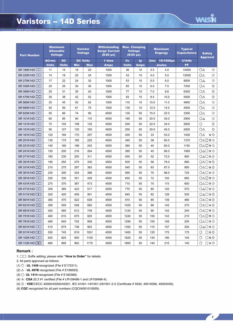
SR 180K20D □□ 11 14 16 20 2000 36 20 10 12 27000 ○△ ◇
SR 220K20D □□ 14 18 20 24 2000 43 20 13 15 20000 ○△ ◇
SR 270K20D □□ 17 22 24 30 2000 53 20 15 17 15000 ○△ ◇
SR 330K20D □□ 20 26 30 36 2000 65 20 22 22 12200 ○△ ◇
SR 390K20D □□ 25 31 35 43 2000 77 20 24 26 10000 ○△ ◇
SR 470K20D □□ 30 38 42 52 2000 93 20 30 33 9350 ○△ ◇
SR 560K20D □□ 35 45 50 62 2000 110 20 35 38 8000 ○△ ◇
SR 680K20D □□ 40 56 61 75 2000 135 20 40 43 6800 ○△ ◇
SR 820K20D □□ 50 66 74 90 6500 135 100 37 48 5600 ○△ ◇
SR 101K20D □□ 60 85 90 110 6500 165 100 38 50 4700 ○△ ◇
SR 121K20D □□ 75 102 108 132 6500 200 100 40 55 4100 ○△ ◇
SR 151K20D □□ 95 127 135 165 6500 250 100 50 70 3200 ○△ ◇
SR 181K20D □□ 120 160 170 207 6500 300 100 60 85 2500 ○△ ☆◇
SR 201K20D □□ 130 175 185 225 6500 340 100 70 95 2200 ○△□☆◇
SR 221K20D □□ 140 180 198 242 6500 360 100 75 100 2000 ○△□☆◇
SR 241K20D □□ 150 200 216 264 6500 395 100 82 110 1900 ○△□☆◇
SR 271K20D □□ 180 230 255 311 6500 455 100 90 127 1700 ○△□☆◇
SR 301K20D □□ 195 250 270 330 6500 505 100 100 135 1540 ○△□☆◇
SR 331K20D □□ 210 275 297 363 6500 545 100 110 148 1400 ○△□☆◇
SR 361K20D □□ 230 300 324 396 6500 595 100 120 163 1320 ○△□☆◇
SR 391K20D □□ 250 330 351 429 6500 650 100 130 180 1210 ○△□☆◇
SR 431K20D □□ 275 370 387 473 6500 710 100 140 190 1120 ○△□☆◇
SR 471K20D □□ 300 385 423 517 6500 775 100 150 220 1000 ○△□☆◇
SR 511K20D □□ 320 420 459 561 6500 840 100 152 222 950 ○△□☆◇
SR 561K20D □□ 360 470 522 638 6500 910 100 154 226 900 ○△□☆◇
SR 621K20D □□ 390 505 558 682 6500 1025 100 158 228 770 ○△□☆◇
SR 681K20D □□ 420 560 612 748 6500 1120 100 160 230 700 ○△□☆◇
SR 751K20D □□ 460 615 675 825 6500 1240 100 175 255 640 ○△□☆◇
SR 781K20D □□ 485 640 702 858 6500 1290 100 180 265 590 ○△□☆◇
SR 821K20D □□ 510 675 738 902 6500 1350 100 190 282 510 ○△□☆◇
SR 911K20D □□ 550 745 819 1001 6500 1400 100 215 310 430 ○ □☆◇
SR 102K20D □□ 625 825 900 1100 6500 1620 100 230 342 380 ○ □☆◇
SR 112K20D □□ 680 895 962 1175 6500 1800 100 250 383 340 ○ □☆◇
Varistors - 20D Series
Remark :1. □□ : Suffix adding; please refer “How to Order” for details.2. All parts approved as follows:(1) ○ : UL 1449 recognized (File # E172311). (2) △ : UL 497B recognized (File # E199593). (3) □ : UL 1414 recognized (File # E182369). (4) ☆ : CSA 22.2 #1 certified (File # LR109496-1 and LR109496-4). (5) ◇ : VDE/CECC 42000/42200/42201, IEC 61051-1/61051-2/61051-2-2 (Certificate # 5932, 40010090, 40003435).(6) CQC recognized for all part numbers (CQC04001010931).
7
www.passivecomponent.com
9
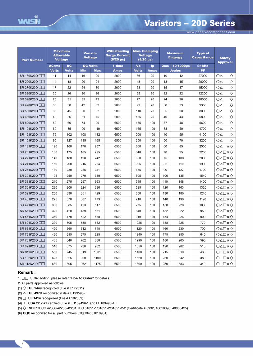
Varistors - 25D Series
Part Number
Maximum Allowable Voltage
Varistor Voltage
WithstandingSurge Current
(8/20 µs)
Max. Clamping Voltage (8/20 µs)
Maximum Engergy
Typical Capacitance Safety
ApprovalACrms DC DC Volts 1 time Vc Ip 2ms 10/1000µs @1kHz
Volts Volts Min Max Amps Volts Amps Joules PF
SR 181K25D □□ 120 160 170 207 18000 300 100 90 180 3900 ○ ☆
SR 201K25D □□ 130 175 185 225 18000 340 100 100 200 3600 ○ ☆
SR 221K25D □□ 140 180 198 242 18000 360 100 105 225 3300 ○ ☆
SR 241K25D □□ 150 200 216 264 18000 395 100 110 235 3050 ○ ☆
SR 271K25D □□ 180 230 255 311 18000 455 100 120 245 2600 ○ ☆
SR 301K25D □□ 195 250 270 330 18000 505 100 125 255 2400 ○ ☆
SR 331K25D □□ 210 275 297 363 18000 545 100 130 270 2200 ○ ☆
SR 361K25D □□ 230 300 324 396 18000 595 100 160 315 2050 ○ ☆
SR 391K25D □□ 250 330 351 429 18000 650 100 175 342 1900 ○ ☆
SR 431K25D □□ 275 370 387 473 18000 710 100 190 370 1700 ○ ☆
SR 471K25D □□ 300 385 423 517 18000 775 100 200 390 1600 ○ ☆
SR 511K25D □□ 320 420 459 561 18000 840 100 210 422 1400 ○ ☆
SR 561K25D □□ 360 470 522 638 18000 910 100 215 460 1200 ○ ☆
SR 621K25D □□ 390 505 558 682 18000 1025 100 225 495 1800 ○ ☆
SR 681K25D □□ 420 560 612 748 18000 1120 100 230 515 1100 ○ ☆
SR 751K25D □□ 460 615 675 825 18000 1240 100 250 530 1000 ○ ☆
SR 781K25D □□ 485 640 702 858 18000 1290 100 260 540 980 ○ ☆
SR 821K25D □□ 510 675 738 902 18000 1350 100 270 550 920 ○ ☆
SR 911K25D □□ 550 745 819 1001 18000 1400 100 300 600 880 ○ ☆
SR 102K25D □□ 625 825 900 1100 18000 1620 100 340 630 760 ○ ☆
SR 112K25D □□ 680 895 962 1175 18000 1800 100 390 700 650 ○ ☆
Remark :1. □□ : Suffix adding; please refer “How to Order” for details.2. All parts approved as follows:(1) ○ : UL 1449 recognized (File # E172311). (2) △ : UL 497B recognized (File # E199593). (3) □ : UL 1414 recognized (File # E182369). (4) ☆ : CSA 22.2 #1 certified (File # LR109496-1 and LR109496-4). (5) ◇ : VDE/CECC 42000/42200/42201, IEC 61051-1/61051-2/61051-2-2 (Certificate # 5932, 40010090, 40003435).(6) CQC recognized for all part numbers (CQC04001010932).
8

www.passivecomponent.com
10
Varistors - 5E Series
Part Number
Maximum Allowable Voltage
Varistor Voltage
WithstandingSurge Current
(8/20 µs)
Max. Clamping Voltage (8/20 µs)
Maximum Engergy
Typical Capacitance Safety
ApprovalACrms DC DC Volts 1 time Vc Ip 10/1000µs @1kHz
Volts Volts Min Max Amps Volts Amps Joules PF
SR 820K05E □□ 50 66 74 90 800 135 5 3.5 355 ○△
SR 181K05E □□ 120 160 170 207 800 320 5 8.0 130 ○
SR 201K05E □□ 130 175 185 225 800 340 5 8.5 120 ○△□☆
SR 221K05E □□ 140 180 198 242 800 360 5 9.0 110 ○△□☆
SR 241K05E □□ 150 200 216 264 800 395 5 10.5 100 ○△□☆
SR 271K05E □□ 180 230 255 311 800 475 5 11.0 90 ○△□☆
SR 301K05E □□ 195 250 270 330 800 525 5 12.0 84 □
SR 331K05E □□ 210 275 297 363 800 540 5 13.0 75 ○△□☆
SR 361K05E □□ 230 300 324 396 800 595 5 16.0 69 ○ □☆
SR 391K05E □□ 250 330 351 429 800 650 5 17.0 63 ○ □☆
SR 431K05E □□ 275 370 387 473 800 710 5 20.0 57 ○ □☆
SR 471K05E □□ 300 385 423 517 800 775 5 21.0 50 ○△□☆
SR 511K05E □□ 320 420 459 561 800 865 5 22.0 35 □
SR 561K05E □□ 360 470 522 638 800 960 5 23.0 32 □
SR 621K05E □□ 390 505 558 682 800 1040 5 25.0 30 □
SR 681K05E □□ 420 560 612 748 800 1120 5 26.0 27 □
Part Number
Maximum Allowable Voltage
Varistor Voltage
WithstandingSurge Current
(8/20 µs)
Max. Clamping Voltage (8/20 µs)
Maximum Engergy
Typical Capacitance Safety
ApprovalACrms DC DC Volts 1 time Vc Ip 10/1000µs @1kHz
Volts Volts Min Max Amps Volts Amps Joules PF
SR 820K07E □□ 50 66 74 90 1750 135 10 7.0 790 ○△ ◇
SR 181K07E □□ 120 160 170 207 1750 320 10 16.0 210 ○ ◇
SR 201K07E □□ 130 175 185 225 1750 340 10 17.5 200 ○△□☆◇
SR 221K07E □□ 140 180 198 242 1750 360 10 19.0 190 ○△□☆◇
SR 241K07E □□ 150 200 216 264 1750 395 10 21.0 170 ○△□☆◇
SR 271K07E □□ 180 230 255 311 1750 475 10 24.0 150 ○△□☆◇
SR 301K07E □□ 195 250 270 330 1750 525 10 26.0 140 □ ◇
SR 331K07E □□ 210 275 297 363 1750 540 10 28.0 130 ○△□☆◇
SR 361K07E □□ 230 300 324 396 1750 595 10 32.0 123 ○ □☆◇
SR 391K07E □□ 250 330 351 429 1750 650 10 35.0 116 ○ □☆◇
SR 431K07E □□ 275 370 387 473 1750 710 10 40.0 108 ○ □☆◇
SR 471K07E □□ 300 385 423 517 1750 775 10 42.0 100 ○△□☆◇
SR 511K07E □□ 320 420 459 561 1750 850 10 46.0 78 □ ◇
SR 561K07E □□ 360 470 522 638 1750 960 10 47.0 75 □ ◇
SR 621K07E □□ 390 505 558 682 1750 1040 10 51.0 72 □ ◇
SR 681K07E □□ 420 560 612 748 1750 1120 10 57.0 69 □ ◇
1. □□ : Suffix adding; please refer “How to Order” for details. 2. Safety approval: please refer to “Remark” above.
9
Remark :1. □□ : Suffix adding; please refer “How to Order” for details.2. All parts approved as follows:(1) ○ : UL 1449 recognized (File # E172311). (2) △ : UL 497B recognized (File # E199593). (3) □ : UL 1414 recognized (File # E182369). (4) ☆ : CSA 22.2 #1 certified (Certificate # 1129226). (5) ◇ : VDE/CECC 42000/42200/42201 (Certificate # 40003435). VDE approval of 05E and 20E series is pending.(6) CQC recognized for all E Series (CQC04001010926 ~ CQC04001010932).

www.passivecomponent.com
11
Varistors - 10E Series
Part Number
Maximum Allowable Voltage
Varistor Voltage
WithstandingSurge Current
(8/20 µs)
Max. Clamping Voltage (8/20 µs)
Maximum Engergy
Typical Capacitance Safety
ApprovalACrms DC DC Volts 1 time Vc Ip 10/1000µs @1kHz
Volts Volts Min Max Amps Volts Amps Joules PF
SR 820K10E □□ 50 66 74 90 3500 135 25 14.0 1780 ○△ ◇
SR 181K10E □□ 120 160 170 207 3500 320 25 33.0 460 ○ ◇
SR 201K10E □□ 130 175 185 225 3500 340 25 35.0 430 ○△□☆◇
SR 221K10E □□ 140 180 198 242 3500 360 25 39.0 410 ○△□☆◇
SR 241K10E □□ 150 200 216 264 3500 395 25 42.0 380 ○△□☆◇
SR 271K10E □□ 180 230 255 311 3500 450 25 49.0 350 ○△□☆◇
SR 301K10E □□ 195 250 270 330 3500 505 25 53.0 320 □ ◇
SR 331K10E □□ 210 275 297 363 3500 540 25 58.0 300 ○△□☆◇
SR 361K10E □□ 230 300 324 396 3500 595 25 65.0 285 ○ □☆◇
SR 391K10E □□ 250 330 351 429 3500 650 25 70.0 270 ○ □☆◇
SR 431K10E □□ 275 370 387 473 3500 710 25 80.0 255 ○ □☆◇
SR 471K10E □□ 300 385 423 517 3500 775 25 85.0 230 ○△□☆◇
SR 511K10E □□ 320 420 459 561 3500 840 25 92.0 210 ○△□☆◇
SR 561K10E □□ 360 470 522 638 3500 910 25 97.0 170 ○ □☆◇
SR 621K10E □□ 390 505 558 682 3500 1025 25 107.0 146 □☆◇
SR 681K10E □□ 420 560 612 748 3500 1120 25 110.0 136 □☆◇
SR 751K10E □□ 460 615 675 825 3500 1240 25 115.0 124 □☆◇
SR 781K10E □□ 485 640 702 858 3500 1290 25 120.0 120 □☆◇
SR 821K10E □□ 510 675 738 902 3500 1350 25 125.0 110 ○△□☆◇
SR 911K10E □□ 550 745 819 1001 3500 1400 25 130.0 90 ○ □ ◇
SR 102K10E □□ 625 725 900 1100 3500 1620 25 145.0 80 □ ◇
SR 112K10E □□ 680 895 962 1175 3500 1815 25 155.0 70 ○ □ ◇
1. □□ : Suffix adding; please refer “How to Order” for details. 2. Safety approval: please refer to “Remark” on page 9.
Part Number
Maximum Allowable Voltage
Varistor Voltage
WithstandingSurge Current
(8/20 µs)
Max. Clamping Voltage (8/20 µs)
Maximum Engergy
Typical Capacitance Safety
ApprovalACrms DC DC Volts 1 time Vc Ip 10/1000µs @1kHz
Volts Volts Min Max Amps Volts Amps Joules PF
SR 820K14E □□ 50 66 74 90 6000 135 50 28.0 3310 ○△ ◇
SR 181K14E □□ 120 160 170 207 6000 320 50 56.0 800 ○ ◇
SR 201K14E □□ 130 175 185 225 6000 330 50 70.0 770 ○△□☆◇
SR 221K14E □□ 140 180 198 242 6000 360 50 78.0 740 ○△□☆◇
SR 241K14E □□ 150 200 216 264 6000 395 50 84.0 700 ○△□☆◇
SR 271K14E □□ 180 230 255 311 6000 450 50 99.0 640 ○△□☆◇
SR 301K14E □□ 195 250 270 330 6000 505 50 107.0 620 □ ◇
SR 331K14E □□ 210 275 297 363 6000 545 50 115.0 580 ○△□☆◇
SR 361K14E □□ 230 300 324 396 6000 595 50 140.0 540 ○ □☆◇
SR 391K14E □□ 250 330 351 429 6000 650 50 150.0 500 ○ □☆◇
SR 431K14E □□ 275 370 387 473 6000 710 50 165.0 460 ○ □☆◇
SR 471K14E □□ 300 385 423 517 6000 775 50 175.0 400 ○△□☆◇
SR 511K14E □□ 320 420 459 561 6000 840 50 190.0 350 ○△□☆◇
SR 561K14E □□ 360 470 522 638 6000 910 50 210.0 320 ○ □☆◇
SR 621K14E □□ 390 505 558 682 6000 1025 50 215.0 270 □☆◇
SR 681K14E □□ 420 560 612 748 6000 1120 50 225.0 250 □☆◇
SR 751K14E □□ 460 615 675 825 6000 1240 50 230.0 230 □☆◇
SR 781K14E □□ 485 640 702 858 6000 1290 50 235.0 210 □☆◇
SR 821K14E □□ 510 675 738 902 6000 1350 50 240.0 190 ○△□☆◇
SR 911K14E □□ 550 745 819 1001 6000 1400 50 255.0 170 ○ □ ◇
SR 102K14E □□ 625 725 900 1100 6000 1620 50 290.0 165 □ ◇
SR 112K14E □□ 680 895 962 1175 6000 1800 50 310.0 140 ○ □ ◇
1. □□ : Suffix adding; please refer “How to Order” for details. 2. Safety approval: please refer to “Remark” on page 9.
10
www.passivecomponent.com
12
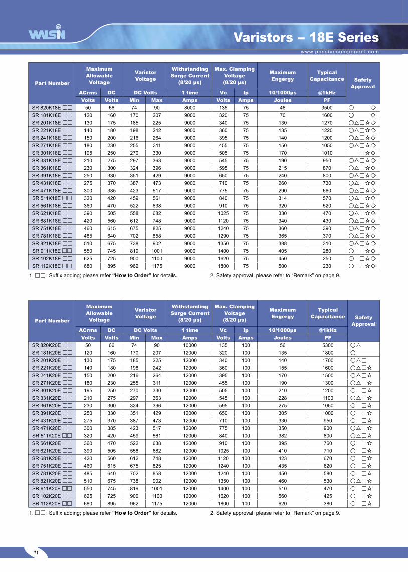
Varistors - 18E Series
Part Number
Maximum Allowable Voltage
Varistor Voltage
WithstandingSurge Current
(8/20 µs)
Max. Clamping Voltage (8/20 µs)
Maximum Engergy
Typical Capacitance Safety
ApprovalACrms DC DC Volts 1 time Vc Ip 10/1000µs @1kHz
Volts Volts Min Max Amps Volts Amps Joules PF
SR 820K18E □□ 50 66 74 90 8000 135 75 46 3500 ○ ◇
SR 181K18E □□ 120 160 170 207 9000 320 75 70 1600 ○ ◇
SR 201K18E □□ 130 175 185 225 9000 340 75 130 1270 ○△□☆◇
SR 221K18E □□ 140 180 198 242 9000 360 75 135 1220 ○△□☆◇
SR 241K18E □□ 150 200 216 264 9000 395 75 140 1200 ○△□☆◇
SR 271K18E □□ 180 230 255 311 9000 455 75 150 1050 ○△□☆◇
SR 301K18E □□ 195 250 270 330 9000 505 75 170 1010 □☆◇
SR 331K18E □□ 210 275 297 363 9000 545 75 190 950 ○△□☆◇
SR 361K18E □□ 230 300 324 396 9000 595 75 215 870 ○△□☆◇
SR 391K18E □□ 250 330 351 429 9000 650 75 240 800 ○△□☆◇
SR 431K18E □□ 275 370 387 473 9000 710 75 260 730 ○△□☆◇
SR 471K18E □□ 300 385 423 517 9000 775 75 290 660 ○△□☆◇
SR 511K18E □□ 320 420 459 561 9000 840 75 314 570 ○△□☆◇
SR 561K18E □□ 360 470 522 638 9000 910 75 320 520 ○△□☆◇
SR 621K18E □□ 390 505 558 682 9000 1025 75 330 470 ○△□☆◇
SR 681K18E □□ 420 560 612 748 9000 1120 75 340 430 ○△□☆◇
SR 751K18E □□ 460 615 675 825 9000 1240 75 360 390 ○△□☆◇
SR 781K18E □□ 485 640 702 858 9000 1290 75 365 370 ○△□☆◇
SR 821K18E □□ 510 675 738 902 9000 1350 75 388 310 ○△□☆◇
SR 911K18E □□ 550 745 819 1001 9000 1400 75 405 280 ○ □☆◇
SR 102K18E □□ 625 725 900 1100 9000 1620 75 450 250 ○ □☆◇
SR 112K18E □□ 680 895 962 1175 9000 1800 75 500 230 ○ □☆◇
1. □□ : Suffix adding; please refer “How to Order” for details. 2. Safety approval: please refer to “Remark” on page 9.
Part Number
Maximum Allowable Voltage
Varistor Voltage
WithstandingSurge Current
(8/20 µs)
Max. Clamping Voltage (8/20 µs)
Maximum Engergy
Typical Capacitance Safety
ApprovalACrms DC DC Volts 1 time Vc Ip 10/1000µs @1kHz
Volts Volts Min Max Amps Volts Amps Joules PF
SR 820K20E □□ 50 66 74 90 10000 135 100 56 5300 ○△
SR 181K20E □□ 120 160 170 207 12000 320 100 135 1800 ○
SR 201K20E □□ 130 175 185 225 12000 340 100 140 1700 ○△□
SR 221K20E □□ 140 180 198 242 12000 360 100 155 1600 ○△□☆
SR 241K20E □□ 150 200 216 264 12000 395 100 170 1500 ○△□☆
SR 271K20E □□ 180 230 255 311 12000 455 100 190 1300 ○△□☆
SR 301K20E □□ 195 250 270 330 12000 505 100 210 1200 ○ □☆
SR 331K20E □□ 210 275 297 363 12000 545 100 228 1100 ○△□☆
SR 361K20E □□ 230 300 324 396 12000 595 100 275 1050 ○ □☆
SR 391K20E □□ 250 330 351 429 12000 650 100 305 1000 ○ □☆
SR 431K20E □□ 275 370 387 473 12000 710 100 330 950 ○ □☆
SR 471K20E □□ 300 385 423 517 12000 775 100 350 900 ○△□☆
SR 511K20E □□ 320 420 459 561 12000 840 100 382 800 ○△□☆
SR 561K20E □□ 360 470 522 638 12000 910 100 395 760 ○ □☆
SR 621K20E □□ 390 505 558 682 12000 1025 100 410 710 ○ □☆
SR 681K20E □□ 420 560 612 748 12000 1120 100 423 670 ○ □☆
SR 751K20E □□ 460 615 675 825 12000 1240 100 435 620 ○ □☆
SR 781K20E □□ 485 640 702 858 12000 1240 100 450 580 ○ □☆
SR 821K20E □□ 510 675 738 902 12000 1350 100 460 530 ○△□☆
SR 911K20E □□ 550 745 819 1001 12000 1400 100 510 470 ○ □☆
SR 102K20E □□ 625 725 900 1100 12000 1620 100 560 425 ○ □☆
SR 112K20E □□ 680 895 962 1175 12000 1800 100 620 380 ○ □☆
1. □□ : Suffix adding; please refer “How to Order” for details. 2. Safety approval: please refer to “Remark” on page 9.
11

www.passivecomponent.com
13
V-I CURVE
12
8/20µs
8/20µs
8/20µs
8/20µs
8/20µs
8/20µs

www.passivecomponent.com
14
V-I CURVE
13
8/20µs
8/20µs
8/20µs8/20µs
8/20µs
8/20µs

www.passivecomponent.com
15
V-I CURVE
14
8/20µs
8/20µs
8/20µs 8/20µs
8/20µs

www.passivecomponent.com
16
Packing Specification (5Ø - 25Ø Series)
A.Bulk Packing :
Disk size mm Voltage BDV Q’ty pcs/bag Q’ty pcs/Carton
Diameter 05 All 1000 10000
Diameter 07 All 500 5000
Diameter 10180K-471K 500 5000
Above 511K 300 3000
Diameter 14180K-751K 300 3000
Above 781K 200 2000
Diameter 18 All 200 2000
Diameter 20180K-621K 100 1000
Above 681K 50 500
Diameter 25180K-621K 50 500
Above 681K 30 300
L approx.395mm
W approx.285mm
H approx. 180mm
B.Taping Packing :
Disk size Varistor VoltageAMMO BOX REEL
PCS / BOX BOX / CARTON PCS / REEL REELS / BOX BOX / CARTON
5Ø ≤ 431K 1500 10 1500 2 5
5Ø ≥ 471K 1000 10 1000 2 5
7Ø ≤ 431K 1500 10 1500 2 5
7Ø ≥ 471K 1000 10 1000 2 5
10Ø ≤ 431K 500 10 500 2 5
10Ø ≥ 471K 300 10 300 2 5
14Ø ≤ 431K 500 8 500 2 5
14Ø ≥ 471K 300 8 300 2 5
18Ø ≤ 431K 500 8 500 2 5
18Ø ≥ 471K 300 8 300 2 5
20Ø ≤ 431K 500 8 500 2 5
20Ø ≥ 471K 300 8 300 2 5
■Dimensions of Ammo Box and Real :
W approx. 50mm
D 350ø max
A approx. 30ø
B approx. 95øDisk size A (max.) B (max.) C (max.)
5Ø 60 mm 250 mm 340 mm
7Ø 60 mm 250 mm 340 mm
10Ø 60 mm 250 mm 340 mm
14Ø 60 mm 250 mm 340 mm
18Ø, 20Ø 60 mm 250 mm 340 mm
■Taping Code :
Varistor series Lead spacing Packing typeLead type
Straight Outward crimped Inward crimped Inline crimped
5D, 5E 5 mm AmmoReel
T11T1
T17T3
T1DT14
T1WT32
7D, 7E 5 mm AmmoReel
T11T1
T17T3
T1DT14
T1WT32
10D, 10E 7.5 mm AmmoReel
T36T19
T1UT1N
T8T16
T43T4
14D, 14E 7.5 mm AmmoReel
T36T19
T1UT1N
T8T16
T43T4
18E 7.5 mm AmmoReel
T44T1H
T45T1X
T40T4X
T2T25
20D, 20E 10 mm AmmoReel
T5T30
T50T2X
T35T2D
T60T3X
15
Note: Ammo box and reel quantity may vary. Please contact sales for details.
www.passivecomponent.com
17
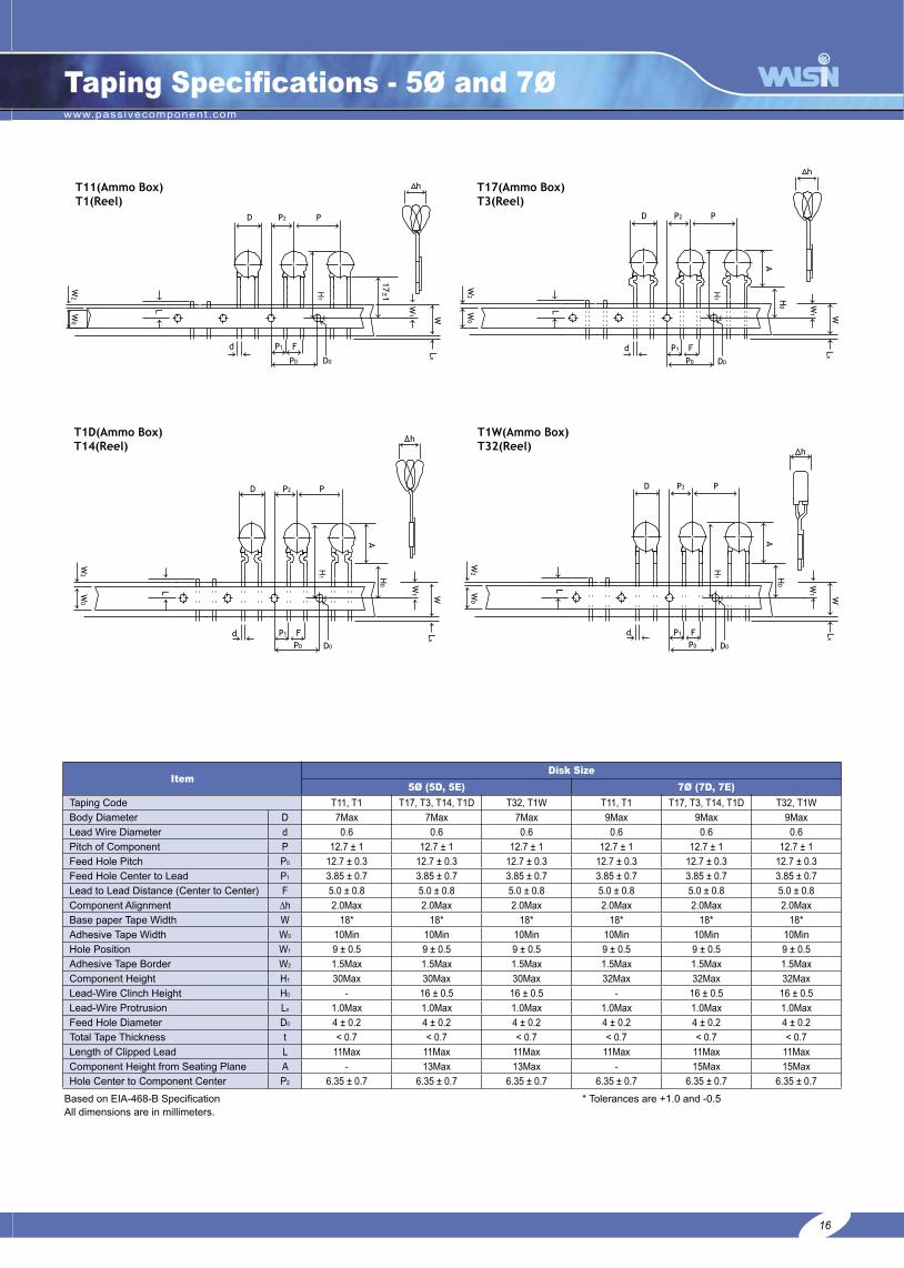
Taping Specifications - 5Ø and 7Ø
ItemDisk Size
5Ø (5D, 5E) 7Ø (7D, 7E)
Taping Code T11, T1 T17, T3, T14, T1D T32, T1W T11, T1 T17, T3, T14, T1D T32, T1W
Body Diameter D 7Max 7Max 7Max 9Max 9Max 9Max
Lead Wire Diameter d 0.6 0.6 0.6 0.6 0.6 0.6
Pitch of Component P 12.7 ± 1 12.7 ± 1 12.7 ± 1 12.7 ± 1 12.7 ± 1 12.7 ± 1
Feed Hole Pitch P0 12.7 ± 0.3 12.7 ± 0.3 12.7 ± 0.3 12.7 ± 0.3 12.7 ± 0.3 12.7 ± 0.3
Feed Hole Center to Lead P1 3.85 ± 0.7 3.85 ± 0.7 3.85 ± 0.7 3.85 ± 0.7 3.85 ± 0.7 3.85 ± 0.7
Lead to Lead Distance (Center to Center) F 5.0 ± 0.8 5.0 ± 0.8 5.0 ± 0.8 5.0 ± 0.8 5.0 ± 0.8 5.0 ± 0.8
Component Alignment ∆h 2.0Max 2.0Max 2.0Max 2.0Max 2.0Max 2.0Max
Base paper Tape Width W 18* 18* 18* 18* 18* 18*
Adhesive Tape Width W0 10Min 10Min 10Min 10Min 10Min 10Min
Hole Position W1 9 ± 0.5 9 ± 0.5 9 ± 0.5 9 ± 0.5 9 ± 0.5 9 ± 0.5
Adhesive Tape Border W2 1.5Max 1.5Max 1.5Max 1.5Max 1.5Max 1.5Max
Component Height H1 30Max 30Max 30Max 32Max 32Max 32Max
Lead-Wire Clinch Height H0 - 16 ± 0.5 16 ± 0.5 - 16 ± 0.5 16 ± 0.5
Lead-Wire Protrusion Lx 1.0Max 1.0Max 1.0Max 1.0Max 1.0Max 1.0Max
Feed Hole Diameter D0 4 ± 0.2 4 ± 0.2 4 ± 0.2 4 ± 0.2 4 ± 0.2 4 ± 0.2
Total Tape Thickness t < 0.7 < 0.7 < 0.7 < 0.7 < 0.7 < 0.7
Length of Clipped Lead L 11Max 11Max 11Max 11Max 11Max 11Max
Component Height from Seating Plane A - 13Max 13Max - 15Max 15Max
Hole Center to Component Center P2 6.35 ± 0.7 6.35 ± 0.7 6.35 ± 0.7 6.35 ± 0.7 6.35 ± 0.7 6.35 ± 0.7
Based on EIA-468-B Specification * Tolerances are +1.0 and -0.5All dimensions are in millimeters.
16
H1
H1
H1
H1

www.passivecomponent.com
18
Taping Specifications - 10Ø and 14Ø
ItemDisk Size
10Ø (10D, 10E) 14Ø (14D, 14E)
Taping Code T19, T36 T1N, T1U, T8, T16 T43, T4 T19, T36 T1N, T1U, T8, T16 T43, T4
Body Diameter D 14Max 14Max 14Max 17.5Max 17.5Max 17.5Max
Lead Wire Diameter d 0.8 ± 0.05 0.8 ± 0.05 0.8 ± 0.05 0.8 ± 0.05 0.8 ± 0.05 0.8 ± 0.05
Pitch of Component P 25.4 ± 1 25.4 ± 1 25.4 ± 1 25.4 ± 1 25.4 ± 1 25.4 ± 1
Hole Center to Component Center P2 12.7 ± 0.3 12.7 ± 0.3 12.7 ± 0.3 12.7 ± 0.3 12.7 ± 0.3 12.7 ± 0.3
Feed Hole Pitch P0 12.7 ± 0.3 12.7 ± 0.3 12.7 ± 0.3 12.7 ± 0.3 12.7 ± 0.3 12.7 ± 0.3
Lead to Lead Distance (Center to Center) F 7.5 ± 0.8 7.5 ± 0.8 7.5 ± 0.8 7.5 ± 0.8 7.5 ± 0.8 7.5 ± 0.8
Component Alignment ∆h 2.0Max 2.0Max 2.0Max 2.0Max 2.0Max 2.0Max
Base paper Tape Width W 18* 18* 18* 18* 18* 18*
Adhesive Tape Width W0 10Min 10Min 10Min 10Min 10Min 10Min
Hole Position W1 9 ± 0.5 9 ± 0.5 9 ± 0.5 9 ± 0.5 9 ± 0.5 9 ± 0.5
Adhesive Tape Border W2 1.5Max 1.5Max 1.5Max 1.5Max 1.5Max 1.5Max
Component Height H1 33Max 38.5Max 35.5Max 37Max 40Max 40Max
Lead-Wire Protrusion Lx 1.0Max 1.0Max 1.0Max 1.0Max 1.0Max 1.0Max
Feed Hole Diameter D0 4 ± 0.2 4 ± 0.2 4 ± 0.2 4 ± 0.2 4 ± 0.2 4 ± 0.2
Total Tape Thickness t < 0.7 < 0.7 < 0.7 < 0.7 < 0.7 < 0.7
Length of Clipped Lead L 11Max 11Max 11Max 11Max 11Max 11Max
Component Height from Seating Plane A - 19.5Max 19.5Max - 22.5Max 22.5Max
Based on EIA-468-B Specification * Tolerances are +1.0 and -0.5All dimensions are in millimeters.
17
H1
www.passivecomponent.com
19
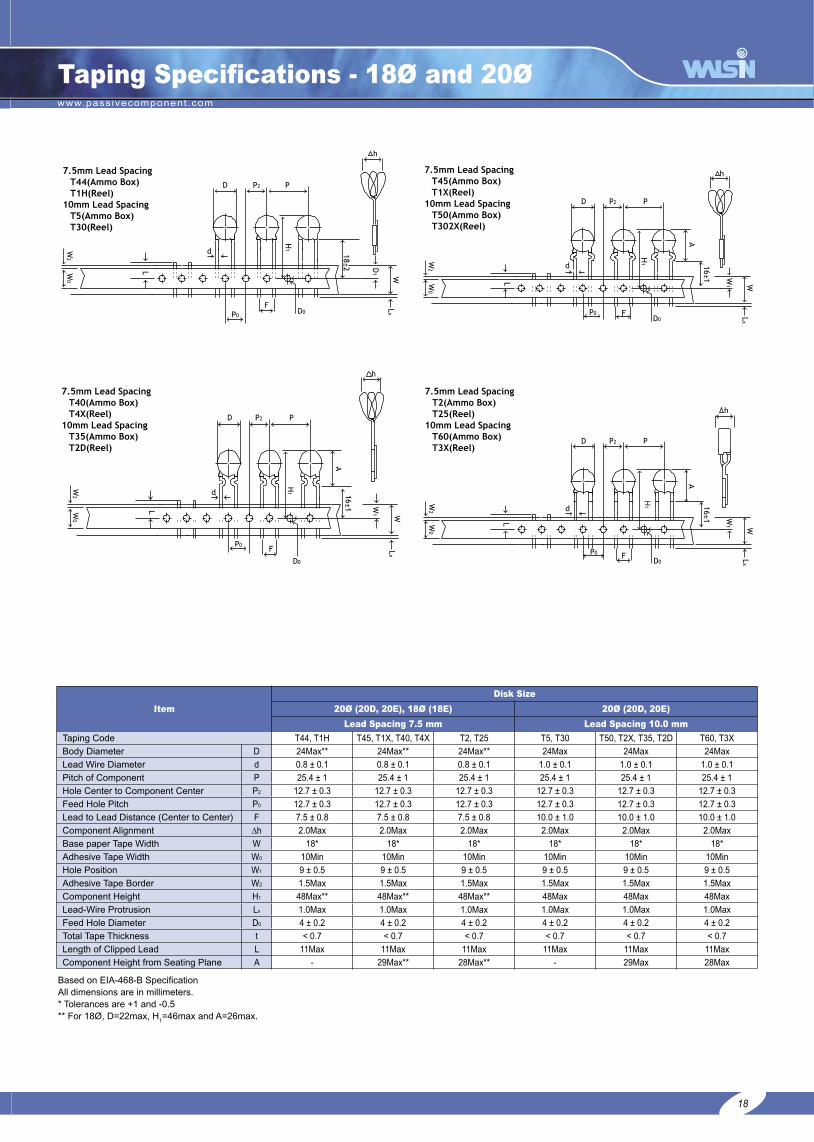
Taping Specifications - 18Ø and 20Ø
Item
Disk Size
20Ø (20D, 20E), 18Ø (18E) 20Ø (20D, 20E)
Lead Spacing 7.5 mm Lead Spacing 10.0 mm
Taping Code T44, T1H T45, T1X, T40, T4X T2, T25 T5, T30 T50, T2X, T35, T2D T60, T3X
Body Diameter D 24Max** 24Max** 24Max** 24Max 24Max 24Max
Lead Wire Diameter d 0.8 ± 0.1 0.8 ± 0.1 0.8 ± 0.1 1.0 ± 0.1 1.0 ± 0.1 1.0 ± 0.1
Pitch of Component P 25.4 ± 1 25.4 ± 1 25.4 ± 1 25.4 ± 1 25.4 ± 1 25.4 ± 1
Hole Center to Component Center P2 12.7 ± 0.3 12.7 ± 0.3 12.7 ± 0.3 12.7 ± 0.3 12.7 ± 0.3 12.7 ± 0.3
Feed Hole Pitch P0 12.7 ± 0.3 12.7 ± 0.3 12.7 ± 0.3 12.7 ± 0.3 12.7 ± 0.3 12.7 ± 0.3
Lead to Lead Distance (Center to Center) F 7.5 ± 0.8 7.5 ± 0.8 7.5 ± 0.8 10.0 ± 1.0 10.0 ± 1.0 10.0 ± 1.0
Component Alignment ∆h 2.0Max 2.0Max 2.0Max 2.0Max 2.0Max 2.0Max
Base paper Tape Width W 18* 18* 18* 18* 18* 18*
Adhesive Tape Width W0 10Min 10Min 10Min 10Min 10Min 10Min
Hole Position W1 9 ± 0.5 9 ± 0.5 9 ± 0.5 9 ± 0.5 9 ± 0.5 9 ± 0.5
Adhesive Tape Border W2 1.5Max 1.5Max 1.5Max 1.5Max 1.5Max 1.5Max
Component Height H1 48Max** 48Max** 48Max** 48Max 48Max 48Max
Lead-Wire Protrusion Lx 1.0Max 1.0Max 1.0Max 1.0Max 1.0Max 1.0Max
Feed Hole Diameter D0 4 ± 0.2 4 ± 0.2 4 ± 0.2 4 ± 0.2 4 ± 0.2 4 ± 0.2
Total Tape Thickness t < 0.7 < 0.7 < 0.7 < 0.7 < 0.7 < 0.7
Length of Clipped Lead L 11Max 11Max 11Max 11Max 11Max 11Max
Component Height from Seating Plane A - 29Max** 28Max** - 29Max 28Max
Based on EIA-468-B SpecificationAll dimensions are in millimeters.* Tolerances are +1 and -0.5** For 18Ø, D=22max, H
1=46max and A=26max.
18
H1

www.passivecomponent.com
20
Big Size Varistor - 32D Series
PartNummber
Maximum Ratings. Electrical Characteristics
Tmax. s dContinuous
RatedVoltage
Rated SinglePulse Transient Varistor Voltage
@ 1mA DC
Maximum ClampingVoltage
@ Test Current 8/20ms
TypicalCapacitance@1KHZ 25°C
AC RMSVolts
DCVolts
Energy Peak
10/1000µsJules
8/20µsKAmps
MinVolts
MaxVolts
Volts Amps PF mm mm mm
SR201K32D □ 130 175 210 30 184 224 340 200 4700 7.5 2.5±1.0 5.7±1.0
SR221K32D □ 140 180 225 30 198 242 360 200 4300 7.5 2.5±1.0 5.5±1.0
SR241K32D □ 150 200 240 30 216 264 395 200 4000 7.5 2.8±1.0 5.4±1.0
SR271K32D □ 180 230 255 30 255 311 455 200 3500 8.5 2.8±1.0 5.2±1.0
SR331K32D □ 210 275 300 30 297 363 550 200 3000 9.0 3.1±1.0 4.8±1.0
SR361K32D □ 230 300 315 30 324 396 595 200 2800 9.0 3.3±1.0 4.6±1.0
SR391K32D □ 250 330 330 30 351 429 650 200 2500 9.0 3.6±1.0 4.4±1.0
SR431K32D □ 275 370 360 30 387 473 710 200 2200 9.0 3.6±1.0 4.2±1.0
SR471K32D □ 300 385 380 30 423 517 775 200 2000 9.7 3.8±1.0 4.2±1.0
SR511K32D □ 320 420 430 30 459 561 840 200 1900 9.7 3.8±1.0 4.0±1.0
SR621K32D □ 390 505 470 30 558 682 1025 200 1600 9.7 4.3±1.0 3.9±1.0
SR681K32D □ 420 560 495 30 612 748 1120 200 1500 9.7 4.6±1.0 3.6±1.0
SR751K32D □ 460 615 520 30 675 825 1240 200 1400 10.5 4.8±1.0 3.3±1.0
SR781K32D □ 485 640 550 30 702 858 1290 200 1300 10.5 4.8±1.0 3.1±1.0
SR821K32D □ 510 675 580 30 738 902 1355 200 1200 10.5 5.1±1.0 2.9±1.0
SR911K32D □ 550 745 620 30 819 1001 1500 200 1150 11.5 5.6±1.0 2.5±1.0
SR951K32D □ 575 765 650 30 855 1043 1570 200 1100 11.5 5.6±1.0 2.3±1.0
SR102K32D □ 625 825 680 30 900 1100 1650 200 1000 12.0 5.8±1.0 2.1±1.0
SR112K32D □ 680 895 760 30 962 1175 1815 200 900 12.0 6.4±1.0 2.1±1.0
□– Part Number Suffix Code ( ie: SR201K32DML) No suffix - Straight Lead L – Straight Lead – Left Side Lead Orientation Q – 90° Bend Lead R – Uncoated Disk – without Leads F – Un-coated Disk – with Leads M – One Side Coated Disk – with one Right Orientation Lead only ML – One Side coated Disk – with one Left Orientation Lead only N – Uncoated Disk – with one Right Orientation Lead only NL – Uncoated Disk – with one Left Orientation Lead only UL 1449 recognized (File # E172311)UL 1414 recognized (File # E182369)CSA 22.2 #1 certified (File #206608M000)Approvals not applicable for uncoated disk productPacking: 340pcs/carton for varistor voltage ≤ 391K, 320pcs/carton for varistor voltage 431K-621K, 260pcs/carton for varistor voltage ≥ 681K. Packing quantity may subject to change without notice, please contact sales for confirmation.
19

www.passivecomponent.com
21
Big Size Varistor - 34mm Single Series
PartNummber
Maximum Ratings. Electrical Characteristics
Tmax. s dContinuous
RatedVoltage
Rated SinglePulse Transient Varistor Voltage
@ 1mA DC
Maximum ClampingVoltage
@ Test Current 8/20ms
TypicalCapacitance@1KHZ 25°C
AC RMSVolts
DCVolts
Energy Peak
10/1000µsJules
8/20µsKAmps
MinVolts
MaxVolts
Volts Amps PF mm mm mm
SR201K34R □ 130 175 310 40 185 225 340 300 10000 7.5 2.5±1.0 5.7±1.0
SR221K34R □ 140 180 330 40 198 242 360 300 9000 7.5 2.5±1.0 5.5±1.0
SR241K34R □ 150 200 360 40 216 264 395 300 8000 7.5 2.8±1.0 5.4±1.0
SR271K34R □ 180 230 390 40 255 311 455 300 7100 8.5 2.8±1.0 5.2±1.0
SR301K34R □ 195 250 405 40 270 330 505 300 6500 9.0 3.0±1.0 5.0±1.0
SR331K34R □ 210 275 430 40 297 363 550 300 6000 9.0 3.1±1.0 4.8±1.0
SR361K34R □ 230 300 460 40 324 396 595 300 5600 9.0 3.3±1.0 4.6±1.0
SR391K34R □ 250 330 490 40 351 429 650 300 5000 9.0 3.6±1.0 4.4±1.0
SR431K34R □ 275 370 550 40 387 473 710 300 4500 9.0 3.6±1.0 4.2±1.0
SR471K34R □ 300 385 600 40 423 517 775 300 4000 9.7 3.8±1.0 4.2±1.0
SR511K34R □ 320 420 640 40 459 561 840 300 3800 9.7 3.8±1.0 4.0±1.0
SR561K34R □ 360 470 710 40 522 638 910 300 3500 9.7 4.0±1.0 4.0±1.0
SR621K34R □ 390 505 800 40 558 682 1025 300 3200 9.7 4.3±1.0 3.9±1.0
SR681K34R □ 420 560 910 40 612 748 1120 300 2900 9.7 4.6±1.0 3.6±1.0
SR751K34R □ 460 615 980 40 675 825 1240 300 2700 10.5 4.8±1.0 3.3±1.0
SR781K34R □ 485 640 1020 40 702 858 1290 300 2500 10.5 5.1±1.0 3.1±1.0
SR821K34R □ 510 675 1100 40 738 902 1355 300 2300 10.5 5.6±1.0 2.9±1.0
SR911K34R □ 550 745 1150 40 819 1001 1500 300 2100 11.5 5.6±1.0 2.5±1.0
SR951K34R □ 575 765 1200 40 855 1043 1570 300 1900 11.5 5.6±1.0 2.3±1.0
SR102K34R □ 625 825 1250 40 900 1100 1650 300 1700 12.0 5.8±1.0 2.1±1.0
SR112K34R □ 680 895 1350 40 962 1175 1815 300 1500 12.0 6.4±1.0 2.1±1.0
□– Part Number Suffix Code (i.e.: SR201K34RML) No suffix – Straight Lead L – Straight Lead – Left Side Lead Orientation Q – 90° Bend Lead R – Uncoated Disk – without Leads F – Un-coated Disk – with Leads M – One Side Coated Disk – with one Right Orientation Lead only ML – One Side coated Disk – with one Left Orientation Lead only N – Uncoated Disk – with one Right Orientation Lead only NL – Uncoated Disk – with one Left Orientation Lead only UL 1449 recognized (File # 172311)UL 1414 pendingCSA 22.2 #1 recognized (File # 206608)Approvals not applicable for uncoated disk productPacking: 340pcs/carton for varistor voltage ≤ 391K, 320pcs/carton for varistor voltage 431K-621K, 260pcs/carton for varistor voltage ≥ 681K. Packing quantity may subject to change without notice, please contact sales for confirmation.
20
www.passivecomponent.com
22
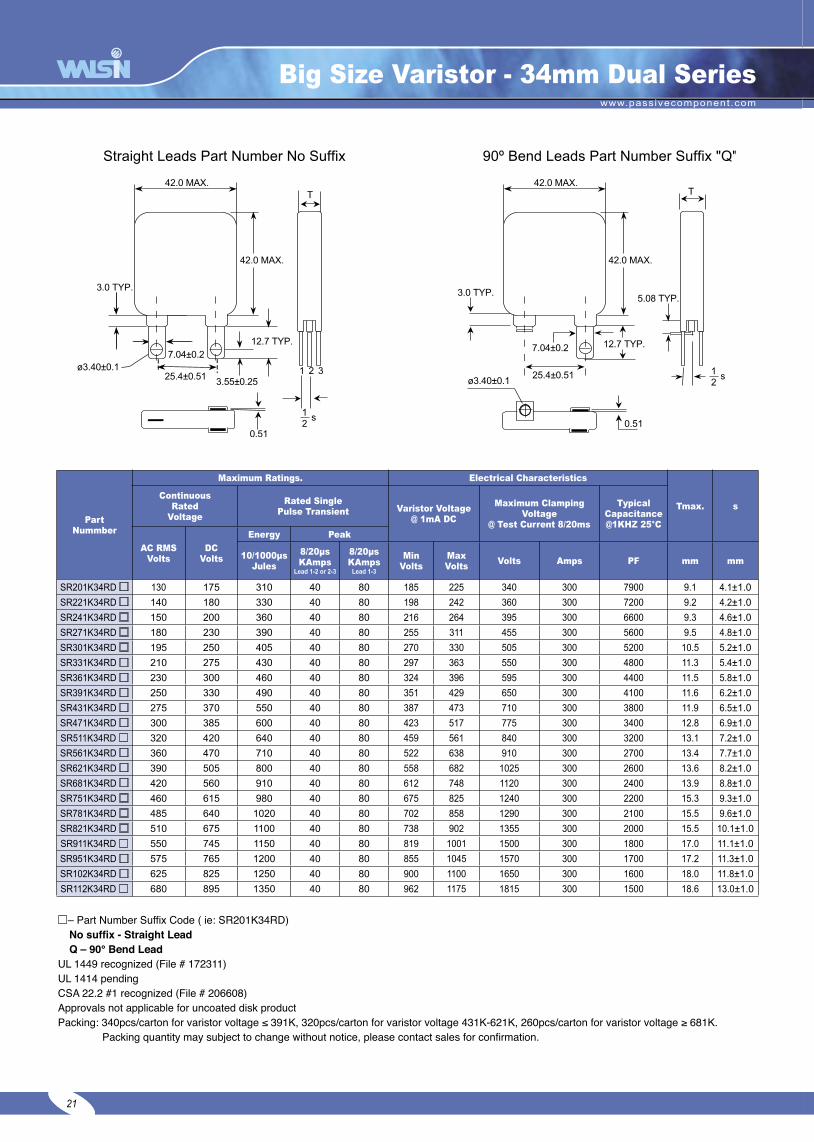
Big Size Varistor - 34mm Dual Series
PartNummber
Maximum Ratings. Electrical Characteristics
Tmax. sContinuous
RatedVoltage
Rated SinglePulse Transient Varistor Voltage
@ 1mA DC
Maximum ClampingVoltage
@ Test Current 8/20ms
TypicalCapacitance@1KHZ 25°C
AC RMSVolts
DCVolts
Energy Peak
10/1000µsJules
8/20µsKAmps
Lead 1-2 or 2-3
8/20µsKAmps
Lead 1-3
MinVolts
MaxVolts
Volts Amps PF mm mm
SR201K34RD □ 130 175 310 40 80 185 225 340 300 7900 9.1 4.1±1.0
SR221K34RD □ 140 180 330 40 80 198 242 360 300 7200 9.2 4.2±1.0
SR241K34RD □ 150 200 360 40 80 216 264 395 300 6600 9.3 4.6±1.0
SR271K34RD □ 180 230 390 40 80 255 311 455 300 5600 9.5 4.8±1.0
SR301K34RD □ 195 250 405 40 80 270 330 505 300 5200 10.5 5.2±1.0
SR331K34RD □ 210 275 430 40 80 297 363 550 300 4800 11.3 5.4±1.0
SR361K34RD □ 230 300 460 40 80 324 396 595 300 4400 11.5 5.8±1.0
SR391K34RD □ 250 330 490 40 80 351 429 650 300 4100 11.6 6.2±1.0
SR431K34RD □ 275 370 550 40 80 387 473 710 300 3800 11.9 6.5±1.0
SR471K34RD □ 300 385 600 40 80 423 517 775 300 3400 12.8 6.9±1.0
SR511K34RD □ 320 420 640 40 80 459 561 840 300 3200 13.1 7.2±1.0
SR561K34RD □ 360 470 710 40 80 522 638 910 300 2700 13.4 7.7±1.0
SR621K34RD □ 390 505 800 40 80 558 682 1025 300 2600 13.6 8.2±1.0
SR681K34RD □ 420 560 910 40 80 612 748 1120 300 2400 13.9 8.8±1.0
SR751K34RD □ 460 615 980 40 80 675 825 1240 300 2200 15.3 9.3±1.0
SR781K34RD □ 485 640 1020 40 80 702 858 1290 300 2100 15.5 9.6±1.0
SR821K34RD □ 510 675 1100 40 80 738 902 1355 300 2000 15.5 10.1±1.0
SR911K34RD □ 550 745 1150 40 80 819 1001 1500 300 1800 17.0 11.1±1.0
SR951K34RD □ 575 765 1200 40 80 855 1045 1570 300 1700 17.2 11.3±1.0
SR102K34RD □ 625 825 1250 40 80 900 1100 1650 300 1600 18.0 11.8±1.0
SR112K34RD □ 680 895 1350 40 80 962 1175 1815 300 1500 18.6 13.0±1.0
2 31 2 31
42.0 MAX.
□– Part Number Suffix Code ( ie: SR201K34RD) No suffix - Straight Lead Q – 90° Bend LeadUL 1449 recognized (File # 172311)UL 1414 pendingCSA 22.2 #1 recognized (File # 206608)Approvals not applicable for uncoated disk product Packing: 340pcs/carton for varistor voltage ≤ 391K, 320pcs/carton for varistor voltage 431K-621K, 260pcs/carton for varistor voltage ≥ 681K. Packing quantity may subject to change without notice, please contact sales for confirmation.
21

www.passivecomponent.com
23
Big Size Varistor - 40D Series
PartNummber
Maximum Ratings. Electrical Characteristics
Tmax. s dContinuous
RatedVoltage
Rated SinglePulse Transient Varistor Voltage
@ 1mA DC
Maximum ClampingVoltage
@ Test Current 8/20ms
TypicalCapacitance@1KHZ 25°C
AC RMSVolts
DCVolts
Energy Peak
10/1000µsJules
8/20µsKAmps
MinVolts
MaxVolts
Volts Amps PF mm mm mm
SR201K40D □ 130 175 310 40 185 225 340 300 10000 7.5 2.5±1.0 5.7±1.0
SR221K40D □ 140 180 330 40 198 242 360 300 9000 7.5 2.5±1.0 5.5±1.0
SR241K40D □ 150 200 360 40 216 264 395 300 8000 7.5 2.8±1.0 5.4±1.0
SR271K40D □ 180 230 390 40 255 311 455 300 7100 8.5 2.8±1.0 5.2±1.0
SR331K40D □ 210 275 460 40 297 363 550 300 6000 9.0 3.1±1.0 4.8±1.0
SR361K40D □ 230 300 475 40 324 396 595 300 5600 9.0 3.3±1.0 4.6±1.0
SR391K40D □ 250 330 490 40 351 429 650 300 5000 9.0 3.6±1.0 4.4±1.0
SR431K40D □ 275 370 550 40 387 473 710 300 4500 9.0 3.6±1.0 4.2±1.0
SR471K40D □ 300 385 600 40 423 517 775 300 4000 9.7 3.8±1.0 4.2±1.0
SR511K40D □ 320 420 640 40 459 561 840 300 3800 9.7 3.8±1.0 4.0±1.0
SR621K40D □ 390 505 800 40 558 682 1025 300 3300 9.7 4.3±1.0 3.9±1.0
SR681K40D □ 420 560 910 40 612 748 1120 300 3000 9.7 4.6±1.0 3.6±1.0
SR751K40D □ 460 615 920 40 675 825 1240 300 2600 10.5 4.8±1.0 3.3±1.0
SR781K40D □ 485 640 930 40 702 858 1290 300 2500 10.5 4.8±1.0 3.1±1.0
SR821K40D □ 510 675 940 40 738 902 1355 300 2300 10.5 5.1±1.0 2.9±1.0
SR911K40D □ 550 745 960 40 819 1001 1500 300 2200 11.5 5.6±1.0 2.5±1.0
SR951K40D □ 575 765 1000 40 855 1043 1570 300 2000 11.5 5.6±1.0 2.3±1.0
SR102K40D □ 625 825 1055 40 900 1100 1650 300 1900 12.0 5.8±1.0 2.1±1.0
SR112K40D □ 680 895 1155 40 962 1175 1815 300 1800 12.0 6.4±1.0 2.1±1.0
□– Part Number Suffix Code ( ie: SR201K40DQ)No suffix - Straight Lead L – Straight Lead – Left Side Lead OrientationQ – 90° Bend Lead R – Uncoated Disk – without LeadsF – Un-coated Disk – with Leads M – One Side Coated Disk – with one Right Orientation Lead onlyML – One Side coated Disk – with one Left Orientation Lead only N – Uncoated Disk – with one Right Orientation Lead onlyNL – Uncoated Disk – with one Left Orientation Lead only UL 1449 recognized (File # E172311)UL 1414 recognized (File # E182369)CSA 22.2 #1 certified (File #206608M000)Approvals not applicable for uncoated disk product Packing: 340pcs/carton for varistor voltage ≤ 391K, 320pcs/carton for varistor voltage 431K-621K, 260pcs/carton for varistor voltage ≥ 681K. Packing quantity may subject to change without notice, please contact sales for confirmation.
22

www.passivecomponent.com
24
Big Size Varistor - 53D Series
PartNummber
Maximum Ratings. Electrical Characteristics
Tmax. s dContinuous
RatedVoltage
Rated SinglePulse Transient Varistor Voltage
@ 1mA DC
Maximum ClampingVoltage
@ Test Current 8/20ms
TypicalCapacitance@1KHZ 25°C
AC RMSVolts
DCVolts
Energy Peak
10/1000µsJules
8/20µsKAmps
MinVolts
MaxVolts
Volts Amps PF mm mm mm
SR201K53D □ 130 175 490 70 185 225 340 500 15000 7.5 2.5±1.0 5.7±1.0
SR221K53D □ 140 180 530 70 198 242 360 500 13800 7.5 2.5±1.0 5.5±1.0
SR241K53D □ 150 200 570 70 216 264 395 500 12500 7.5 2.8±1.0 5.4±1.0
SR271K53D □ 180 230 630 70 255 311 455 500 11000 8.5 2.8±1.0 5.2±1.0
SR331K53D □ 210 275 680 70 297 363 550 500 9000 9.0 3.1±1.0 4.8±1.0
SR361K53D □ 230 300 730 70 324 396 595 500 8500 9.0 3.3±1.0 4.6±1.0
SR391K53D □ 250 330 880 70 351 429 650 500 7500 9.0 3.6±1.0 4.4±1.0
SR431K53D □ 275 370 950 70 387 473 710 500 7000 9.0 3.6±1.0 4.2±1.0
SR471K53D □ 300 385 1000 70 423 517 775 500 6500 9.7 3.8±1.0 4.2±1.0
SR511K53D □ 320 420 1100 70 459 561 840 500 6000 9.7 3.8±1.0 4.0±1.0
SR561K53D □ 360 470 1200 70 522 638 910 500 5600 9.7 4.3±1.0 4.0±1.0
SR621K53D □ 390 505 1300 70 558 682 1025 500 5200 9.7 4.3±1.0 3.9±1.0
SR681K53D □ 420 560 1500 70 612 748 1120 500 4800 9.7 4.6±1.0 3.6±1.0
SR751K53D □ 460 615 1600 70 675 825 1240 500 4300 10.5 4.6±1.0 3.3±1.0
SR781K53D □ 485 640 1650 70 702 858 1290 500 3900 10.5 4.8±1.0 3.1±1.0
SR821K53D □ 510 675 1800 70 738 902 1355 500 3700 10.5 5.1±1.0 2.9±1.0
SR911K53D □ 550 745 2000 70 819 1001 1500 500 3300 11.5 5.6±1.0 2.5±1.0
SR951K53D □ 575 765 2100 70 855 1043 1570 500 3200 11.5 5.6±1.0 2.3±1.0
SR102K53D □ 625 825 2200 70 900 1100 1650 500 3000 11.5 5.8±1.0 2.1±1.0
SR112K53D □ 680 895 2500 70 962 1175 1815 500 2800 11.5 6.4±1.0 2.1±1.0
SR122K53D □ 750 970 2700 70 1062 1300 1980 500 2700 12.6 7.0±1.0 1.5±1.0
□– Part Number Suffix Code ( ie: SR201K53DQ) No suffix - Straight Lead L – Straight Lead – Left Side Lead Orientation Q – 90° Bend Lead R – Uncoated Disk – without Leads F – Un-coated Disk – with Leads M – One Side Coated Disk – with one Right Orientation Lead only ML – One Side coated Disk – with one Left Orientation Lead only N – Uncoated Disk – with one Right Orientation Lead only NL – Uncoated Disk – with one Left Orientation Lead only UL 1449 recognized (File # 172311)UL 1414 pendingCSA 22.2 #1 recognized (File # 206608)Approvals not applicable for uncoated disk product Packing: 170pcs/carton for varistor voltage ≤ 391K, 160pcs/carton for varistor voltage 431K-621K, 130pcs/carton for varistor voltage ≥ 681K. Packing quantity may subject to change without notice, please contact sales for confirmation.
23
www.passivecomponent.com
25
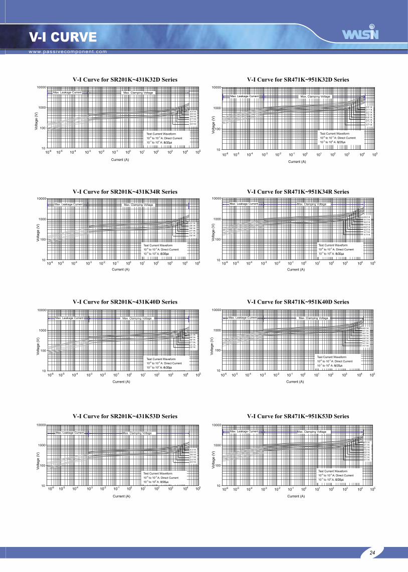
V-I CURVE
24
8/20µs
8/20µs
8/20µs
8/20µs8/20µs
8/20µs
8/20µs
8/20µs

www.passivecomponent.com
25
■Wave Soldering Profile
Thermo-Fuse Varistor (FSR)


Related Documents