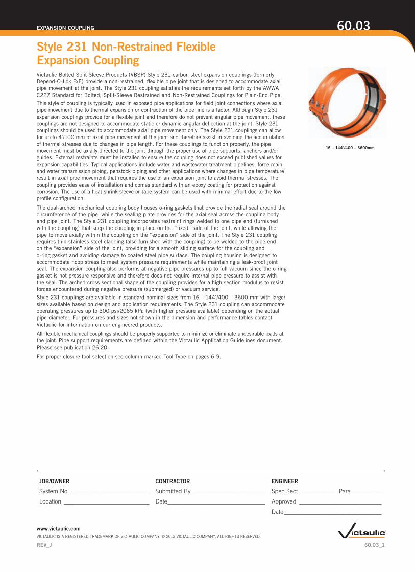
Victaulic Bolted Split-Sleeve Products (VBSP) Style 231 carbon steel expansion couplings (formerly Depend-O-Lok FxE) provide a non-restrained, flexible pipe joint that is designed to accommodate axial pipe movement at the joint. The Style 231 coupling satisfies the requirements set forth by the AWWA C227 Standard for Bolted, Split-Sleeve Restrained and Non-Restrained Couplings for Plain-End Pipe. This style of coupling is typically used in exposed pipe applications for field joint connections where axial pipe movement due to thermal expansion or contraction of the pipe line is a factor. Although Style 231 expansion couplings provide for a flexible joint and therefore do not prevent angular pipe movement, these couplings are not designed to accommodate static or dynamic angular deflection at the joint. Style 231 couplings should be used to accommodate axial pipe movement only. The Style 231 couplings can allow for up to 4" /100 mm of axial pipe movement at the joint and therefore assist in avoiding the accumulation of thermal stresses due to changes in pipe length. For these couplings to function properly, the pipe movement must be axially directed to the joint through the proper use of pipe supports, anchors and/or guides. External restraints must be installed to ensure the coupling does not exceed published values for expansion capabilities. Typical applications include water and wastewater treatment pipelines, force main and water transmission piping, penstock piping and other applications where changes in pipe temperature result in axial pipe movement that requires the use of an expansion joint to avoid thermal stresses. The coupling provides ease of installation and comes standard with an epoxy coating for protection against corrosion. The use of a heat-shrink sleeve or tape system can be used with minimal effort due to the low profile configuration. The dual-arched mechanical coupling body houses o-ring gaskets that provide the radial seal around the circumference of the pipe, while the sealing plate provides for the axial seal across the coupling body and pipe joint. The Style 231 coupling incorporates restraint rings welded to one pipe end (furnished with the coupling) that keep the coupling in place on the “fixed” side of the joint, while allowing the pipe to move axially within the coupling on the “expansion” side of the joint. The Style 231 coupling requires thin stainless steel cladding (also furnished with the coupling) to be welded to the pipe end on the “expansion” side of the joint, providing for a smooth sliding surface for the coupling and o-ring gasket and avoiding damage to coated steel pipe surface. The coupling housing is designed to accommodate hoop stress to meet system pressure requirements while maintaining a leak-proof joint seal. The expansion coupling also performs at negative pipe pressures up to full vacuum since the o-ring gasket is not pressure responsive and therefore does not require internal pipe pressure to assist with the seal. The arched cross-sectional shape of the coupling provides for a high section modulus to resist forces encountered during negative pressure (submerged) or vacuum service. Style 231 couplings are available in standard nominal sizes from 16 – 144"/400 – 3600 mm with larger sizes available based on design and application requirements. The Style 231 coupling can accommodate operating pressures up to 300 psi/2065 kPa (with higher pressure available) depending on the actual pipe diameter. For pressures and sizes not shown in the dimension and performance tables contact Victaulic for information on our engineered products. All flexible mechanical couplings should be properly supported to minimize or eliminate undesirable loads at the joint. Pipe support requirements are defined within the Victaulic Application Guidelines document. Please see publication 26.20. For proper closure tool selection see column marked Tool Type on pages 6-9. 60.03_1 Style 231 Non-Restrained Flexible Expansion Coupling 60.03 EXPANSION COUPLING JOB/OWNER CONTRACTOR ENGINEER System No. __________________________ Submitted By ________________________ Spec Sect ____________ Para __________ Location ____________________________ Date ________________________________ Approved ___________________________ Date ________________________________ www.victaulic.com VICTAULIC IS A REGISTERED TRADEMARK OF VICTAULIC COMPANY. © 2013 VICTAULIC COMPANY. ALL RIGHTS RESERVED. REV_J 16 – 144"/400 – 3600mm

Welcome message from author
This document is posted to help you gain knowledge. Please leave a comment to let me know what you think about it! Share it to your friends and learn new things together.
Transcript
Victaulic Bolted Split-Sleeve Products (VBSP) Style 231 carbon steel expansion couplings (formerly Depend-O-Lok FxE) provide a non-restrained, flexible pipe joint that is designed to accommodate axial pipe movement at the joint. The Style 231 coupling satisfies the requirements set forth by the AWWA C227 Standard for Bolted, Split-Sleeve Restrained and Non-Restrained Couplings for Plain-End Pipe. This style of coupling is typically used in exposed pipe applications for field joint connections where axial pipe movement due to thermal expansion or contraction of the pipe line is a factor. Although Style 231 expansion couplings provide for a flexible joint and therefore do not prevent angular pipe movement, these couplings are not designed to accommodate static or dynamic angular deflection at the joint. Style 231 couplings should be used to accommodate axial pipe movement only. The Style 231 couplings can allow for up to 4"/100 mm of axial pipe movement at the joint and therefore assist in avoiding the accumulation of thermal stresses due to changes in pipe length. For these couplings to function properly, the pipe movement must be axially directed to the joint through the proper use of pipe supports, anchors and/or guides. External restraints must be installed to ensure the coupling does not exceed published values for expansion capabilities. Typical applications include water and wastewater treatment pipelines, force main and water transmission piping, penstock piping and other applications where changes in pipe temperature result in axial pipe movement that requires the use of an expansion joint to avoid thermal stresses. The coupling provides ease of installation and comes standard with an epoxy coating for protection against corrosion. The use of a heat-shrink sleeve or tape system can be used with minimal effort due to the low profile configuration.
The dual-arched mechanical coupling body houses o-ring gaskets that provide the radial seal around the circumference of the pipe, while the sealing plate provides for the axial seal across the coupling body and pipe joint. The Style 231 coupling incorporates restraint rings welded to one pipe end (furnished with the coupling) that keep the coupling in place on the “fixed” side of the joint, while allowing the pipe to move axially within the coupling on the “expansion” side of the joint. The Style 231 coupling requires thin stainless steel cladding (also furnished with the coupling) to be welded to the pipe end on the “expansion” side of the joint, providing for a smooth sliding surface for the coupling and o-ring gasket and avoiding damage to coated steel pipe surface. The coupling housing is designed to accommodate hoop stress to meet system pressure requirements while maintaining a leak-proof joint seal. The expansion coupling also performs at negative pipe pressures up to full vacuum since the o-ring gasket is not pressure responsive and therefore does not require internal pipe pressure to assist with the seal. The arched cross-sectional shape of the coupling provides for a high section modulus to resist forces encountered during negative pressure (submerged) or vacuum service. Style 231 couplings are available in standard nominal sizes from 16 – 144"/400 – 3600 mm with larger sizes available based on design and application requirements. The Style 231 coupling can accommodate operating pressures up to 300 psi/2065 kPa (with higher pressure available) depending on the actual pipe diameter. For pressures and sizes not shown in the dimension and performance tables contact Victaulic for information on our engineered products.
All flexible mechanical couplings should be properly supported to minimize or eliminate undesirable loads at the joint. Pipe support requirements are defined within the Victaulic Application Guidelines document. Please see publication 26.20.
For proper closure tool selection see column marked Tool Type on pages 6-9.
60.03_1
Style 231 Non-Restrained Flexible Expansion Coupling
60.03EXPANSION COUPLING
JOB/OWNER CONTRACTOR ENGINEER
System No. __________________________ Submitted By ________________________ Spec Sect ____________ Para __________
Location ____________________________ Date ________________________________ Approved ___________________________
Date ________________________________
www.victaulic.comVICTAULIC IS A REGISTERED TRADEMARK OF VICTAULIC COMPANY. © 2013 VICTAULIC COMPANY. ALL RIGHTS RESERVED.
REV_J
16 – 144"/400 – 3600mm
SEGMENTED COUPLINGSThe Style 231 dimension tables list the minimum number of coupling housing segments for a particu-lar pipe size. For special applications, expansion couplings are available in two (or more) segments to allow for installation of the coupling over an existing pipe joint or to facilitate ease of handling for larger size couplings. The o-ring gaskets (except Silicone) can be furnished “split” to allow for field bonding when an existing pipe joint configuration does not allow for installation of a complete o-ring onto the pipe end.
PRODUCT GUIDEProduct Style Guide
Submittal Number Style Number Coupling/Body Material Application
60.01 230 Carbon Steel Non-Restrained Coupling
60.02 230S Stainless Steel Non-Restrained Coupling
60.03 231 Carbon Steel Expansion Coupling
60.04 231S Stainless Steel Expansion Coupling
60.05 232 Carbon Steel Restrained Coupling
60.06 232S Stainless Steel Restrained Coupling
60.07 233 Carbon Steel Restrained Coupling For Dynamic Joint Deflection
60.08 233S Stainless Steel Restrained Coupling For Dynamic Joint Deflection
60.09 234 Carbon Steel Restrained Single-Gasket Coupling
60.10 234S Stainless Steel Restrained Single-Gasket Coupling
60.03_2
Style 231 Non-Restrained Flexible Expansion Coupling
60.03EXPANSION COUPLING
www.victaulic.comVICTAULIC IS A REGISTERED TRADEMARK OF VICTAULIC COMPANY. © 2013 VICTAULIC COMPANY. ALL RIGHTS RESERVED.
REV_J
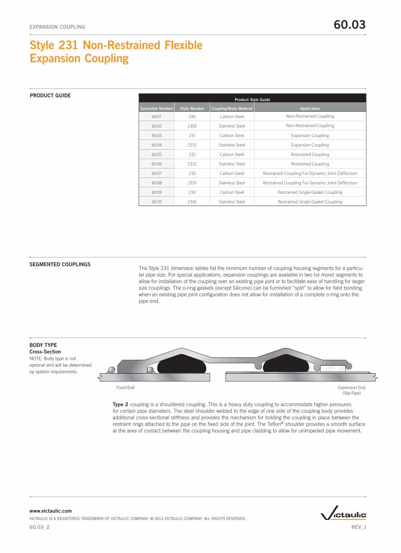
BODY TYPE Cross-Section NOTE: Body type is not optional and will be determined by system requirements.
Type 2 coupling is a shouldered coupling. This is a heavy duty coupling to accommodate higher pressures for certain pipe diameters. The steel shoulder welded to the edge of one side of the coupling body provides additional cross-sectional stiffness and provides the mechanism for holding the coupling in place between the restraint rings attached to the pipe on the fixed side of the joint. The Teflon® shoulder provides a smooth surface at the area of contact between the coupling housing and pipe cladding to allow for unimpeded pipe movement.
Expansion End(Slip Pipe)
Fixed End

COUPLING COMPONENTS
1. Body – Dual arch cross-section.
2. Shoulders
Fixed Side – Rectangular steel bar located at coupling body edge provides additional stiffness, allows for larger o-ring gasket and provides vertical bearing surface for restraint ring.
Expansion Side – Utilizes Teflon® material to provide for a smooth sliding surface in order to accommodate larger expansion values afforded by the Style 231 Type 2 coupling.
3. Closure Plates – Low profile bolt pads for installation and tightening of coupling; gap between plates of installed coupling allows for field flexibility.
4. Sealing Plate – Provides axial seal across the coupling body and pipe joint.
5. O-ring Gaskets – Provide circumferential seal.
6. Fasteners
Studs – High Strength Threaded Rod
Nuts – Heavy Hex Nuts
Washers – SAE small pattern flat washers
7. Restraint Rings – Used to maintain coupling position on the "fixed" end of the pipe.
ONE SEGMENT HOUSING TWO SEGMENT HOUSING
17
6
32
4
5
1
7
6
3
2
45
60.03_3
Style 231 Non-Restrained Flexible Expansion Coupling
60.03EXPANSION COUPLING
www.victaulic.comVICTAULIC IS A REGISTERED TRADEMARK OF VICTAULIC COMPANY. © 2013 VICTAULIC COMPANY. ALL RIGHTS RESERVED.
REV_J
MATERIAL SPECIFICATIONS Body Carbon Steel conforming to ASTM A36
• EPDM -30ºF to +230ºF/-34ºC to +110ºC Cold and hot water within allowable temperature range; dilute acids; excellent resistance to the deteriorative effects of ozone, oxygen, heat and most chemicals not involving hydrocarbons. NOT RECOMMENDED FOR PETROLEUM SERVICES.
• Silicone -30ºF to +350ºF/-34ºC to +177ºC Dry, hot air applications; excellent resistance to many chemicals. NOT RECOMMENDED FOR HOT WATER OR STEAM APPLICATIONS.
• Isoprene -40ºF to +160ºF/-40ºC to +71ºC Water; salt water; sewage; good resistance to oxygen and dilute acids Services listed are general service recommendations only. Refer to a chemical elastomer guide for specific applications and suitability of gasket material for services that are not listed.
• Nitrile -20ºF to +180ºF/-28ºC to +82ºC Water; petroleum products, vegetable and mineral oils; air with oil vapors within allowable tempera-ture range; good resistance to hydrocarbons; acids and bases.
• Fluouroelastomer +20ºF to +300ºF/-7ºC to +149ºC Outstanding resistance to heat and most chemicals.
• Neoprene -30ºF to +180ºF/-34ºC to +82ºC Water and wastewater; good resistance to ozone, effects of UV and some oils.
• Services listed are general service recommendations only. Refer to a chemical elastomer guide for specific applications and suitability of gasket material for services that are not listed.
Shoulders Carbon steel conforming to ASTM A36 (Fixed Side)
Teflon® - PTFE commercial grade (Expansion Side) Closure Plates Carbon Steel conforming to ASTM A36 Sealing Plate Stainless Steel conforming to ASTM A240 316L O-ring Gaskets
Studs - Carbon Steel conforming to ASTM A193 Grade B7 zinc plated. Optional: Stainless Steel conforming to ASTM A193 Grade B8M 316 Class 2 Nuts - Heavy hex nuts Carbon Steel conforming to ASTM A194 Grade 2H zinc plated Optional: Stainless Steel conforming to ASTM A194 Grade 8M 316 Washers - Carbon Steel SAE small pattern flat washers conforming to ASTM F436 SAE pattern zinc plated Optional: Stainless Steel Type 316 SAE pattern.
Stainless Steel conforming to ASTM A240 316L
Fasteners
Restraint Rings Carbon Steel conforming to ASTM A108 Grade 1018 C.S.
Standard (Specify choice on order):
Optional gasket (specify choice on order):
Cladding
60.03_4
Style 231 Non-Restrained Flexible Expansion Coupling
60.03EXPANSION COUPLING
www.victaulic.comVICTAULIC IS A REGISTERED TRADEMARK OF VICTAULIC COMPANY. © 2013 VICTAULIC COMPANY. ALL RIGHTS RESERVED.
REV_J

Liquid Epoxy: Liquid epoxy is applied per AWWA C210, 16 mils minimum DFT and is NSF approved. Epoxy can be applied as a primer for field applied top coat where UV protection due to sunlight exposure is required.
Fusion Bonded Epoxy: Fusion bonded epoxy is applied with an electrostatic spray system using a long cure epoxy powder that offers excellent chemical resistance and corrosion protection. Fusion bonded epoxy is applied per AWWA C213, 12 mils minimum DFT and is NSF61 approved.
Phenolic Alkyd Primer: Phenolic Alkyd primer is a lead-free and chromate-free, fast-drying, corrosion-resistant primer that accepts a variety of high-performance topcoats, but is not recommended for immersion service by itself. This primer system is typically applied at 2 to 3 mils DFT.
Other Coating Systems (Available Upon Request): A water based enamel coating is available. This paint offers an aesthetic coating for minimal protec-tion, short-term installations or where corrosion protection is not a consideration. Fusion bonded nylon for chemical and abrasion resistance, as well as other coatings such as organic zinc primers and hot dipped galvanizing may also be available.
LININGS AND COATINGS
•
Standard (specify choice on order):
•
•
•
Optional (specify choice on order):
60.03_5
Style 231 Non-Restrained Flexible Expansion Coupling
60.03EXPANSION COUPLING
www.victaulic.comVICTAULIC IS A REGISTERED TRADEMARK OF VICTAULIC COMPANY. © 2013 VICTAULIC COMPANY. ALL RIGHTS RESERVED.
REV_J
PIPE END DIMENSIONAL TOLERANCE AND OVALITY
For specific pipe diameter tolerances, pipe ovality (roundness) requirements and minimum/maximum pipe diameter allowance, refer to the tables included in the Installation Manuals, Publications (below) and 26.20 Application Guidelines.
I-231.T2S1/CLAD - Styles 231/231S Expansion Coupling (Type 2, One-Segment with Cladding on Expansion Side of Pipe)I-231.T2S2/CLAD - Styles 231/231S Expansion Coupling (Type 2, Two-Segments with Cladding on Expansion Side of Pipe)

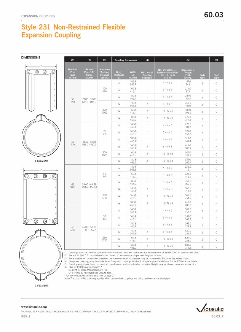
(1) Couplings must be used on pipe with a minimum wall thickness that meets the requirements of AWWA C200 for carbon steel pipe. (2) For actual Pipe O.D. round down to the nearest 1/8" to determine proper coupling size required. (3) For allowable test or transient pressure, the maximum working pressure may be increased to 11/2 times the values shown. (4) 1-segment couplings may be available as 2-segment couplings to allow for in-place pipe installations. Contact Victaulic for details. (5) Coupling weights are based on nominal pipe diameter and include all accessories. Weight may vary based on actual size of pipe. (6) Closure Tool Recommendations:* B= CTM-02 Large Manual Closure Tool C= CTH-01 10-Ton Hydraulic Closure Tool*For more details on closure tools refer to page 17.Note: The data in this table only applies when carbon steel couplings are being used on carbon steel pipe.
1-SEGMENT
2-SEGMENT
DIMENSIONS
Z
Z
(1) (2) (3) Coupling Dimensions (4) (5) (6)
NominaI
Pipe Size
In./mm
Actual Pipe O.D.
Range In./mm
Maximum Working Pressure psi/kPa
Body Thickness
In.
Width (Z)
In./mm
Min. No. of Coupling Segments
No. of Fasteners - Fastener Dimensions
Dia. x Length In. x In.
Approximate
Weight Each
Lbs/Kg.Body Type
Tool Type
16400
15.00 - 16.88381.0 - 428.8
2001375
3/16 14.38 1 4 - 3/4 x 6 97.02 B,C365.3 44.0
3/16 16.38 1 5 - 3/4 x 6 117.02 B,C416.1 53.1
3/16 18.38 1 5 - 3/4 x 6 128.02 B,C466.9 58.1
3002065
1/4 14.38 1 4 - 3/4 x 6 110.02 C365.3 49.9
1/4 16.38 1 5 - 3/4 x 6 132.02 C416.1 59.9
1/4 18.38 1 5 - 3/4 x 6 145.02 C466.9 65.8
18450
17.00 - 18.88431.8 - 479.6
2001375
3/16 14.38 1 4 - 3/4 x 6 106.02 B,C365.3 48.1
3/16 16.38 1 5 - 3/4 x 6 127.02 B,C416.1 57.6
3/16 18.38 1 5 - 3/4 x 6 138.02 B,C466.9 62.6
3002065
1/4 14.38 1 4 - 3/4 x 6 120.02 C365.3 54.4
1/4 16.38 1 5 - 3/4 x 6 143.02 C416.1 64.9
1/4 18.38 1 5 - 3/4 x 6 157.02 C466.9 71.2
20500
19.00 - 21.88482.6 - 555.8
2001375
3/16 14.38 1 4 - 3/4 x 6 115.02 B,C365.3 52.2
3/16 16.38 1 5 - 3/4 x 6 136.02 B,C416.1 61.7
3/16 18.38 1 5 - 3/4 x 6 150.02 B,C466.9 68.0
3002065
1/4 14.38 1 4 - 3/4 x 6 131.02 C365.3 59.4
1/4 16.38 1 5 - 3/4 x 6 155.02 C416.1 70.3
1/4 18.38 1 5 - 3/4 x 6 170.02 C466.9 77.1
24600
22.00 - 26.88558.8 - 682.8
1501035
1/4 14.38 1 4 - 3/4 x 6 155.02 C365.3 70.3
1/4 16.38 1 5 - 3/4 x 6 179.02 C416.1 81.2
1/4 18.38 1 5 - 3/4 x 6 196.02 C466.9 88.9
3002065
3/8 14.38 2 8 - 7/8 x 8 301.02 C365.3 136.5
3/8 16.38 2 10 - 7/8 x 8 377.02 C416.1 171.0
3/8 18.38 2 10 - 7/8 x 8 411.02 C466.9 186.4
60.03_6
Style 231 Non-Restrained Flexible Expansion Coupling
60.03EXPANSION COUPLING
www.victaulic.comVICTAULIC IS A REGISTERED TRADEMARK OF VICTAULIC COMPANY. © 2013 VICTAULIC COMPANY. ALL RIGHTS RESERVED.
REV_J
(1) (2) (3) Coupling Dimensions (4) (5) (6)
NominaI
Pipe Size
In./mm
Actual Pipe O.D.
Range In./mm
Maximum Working Pressure psi/kPa
Body Thickness
In.
Width (Z)
In./mm
Min. No. of Coupling Segments
No. of Fasteners - Fastener Dimensions
Dia. x Length In. x In.
Approximate
Weight Each
Lbs/Kg.Body Type
Tool Type
30750
27.00 - 32.88685.8 - 835.2
100690
1/4 14.38 1 4 - 3/4 x 6 187.02 C365.3 84.8
1/4 16.38 1 5 - 3/4 x 6 214.02 C416.1 97.1
1/4 18.38 1 5 - 3/4 x 6 237.02 C466.9 107.5
3002065
3/8 14.38 2 8 - 7/8 x 8 355.02 C365.3 161.0
3/8 16.38 2 10 - 7/8 x 8 437.02 C416.1 198.2
3/8 18.38 2 10 - 7/8 x 8 479.02 C466.9 217.3
36900
33.00- 38.88838.2 - 987.6
75515
1/4 14.38 1 4 - 3/4 x 6 223.02 C365.3 101.2
1/4 16.38 1 5 - 3/4 x 6 287.02 C416.1 130.2
1/4 18.38 1 5 - 3/4 x 6 314.02 C466.9 142.4
3002065
3/8 14.38 2 8 - 7/8 x 8 412.02 C365.3 186.9
3/8 16.38 2 10 - 7/8 x 8 501.02 C416.1 227.2
3/8 18.38 2 10 - 7/8 x 8 551.02 C466.9 249.9
421050
39.00 - 44.88990.6 - 1140.0
50345
1/4 14.38 1 4 - 3/4 x 6 256.02 C365.3 116.1
1/4 16.38 1 5 - 3/4 x 6 323.02 C416.1 146.5
1/4 18.38 1 5 - 3/4 x 6 353.02 C466.9 160.0
2501725
3/8 14.38 2 8 - 7/8 x 8 466.02 C365.3 211.4
3/8 16.38 2 10 - 7/8 x 8 562.02 C416.1 254.9
3/8 18.38 2 10 - 7/8 x 8 618.02 C466.9 280.3
481200
45.00 - 50.88 1143 - 1292.4
50345
1/4 14.38 1 4 - 3/4 x 6 288.02 C365.3 130.6
1/4 16.38 1 5 - 3/4 x 6 359.02 C416.1 162.8
1/4 18.38 1 5 - 3/4 x 6 393.02 C466.9 178.3
2501725
3/8 14.38 2 8 - 7/8 x 8 520.02 C365.3 235.9
3/8 16.38 2 10 - 7/8 x 8 624.02 C416.1 283.0
3/8 18.38 2 10 - 7/8 x 8 686.02 C466.9 311.2
1-SEGMENT
2-SEGMENT
DIMENSIONS
Z
Z
(1) Couplings must be used on pipe with a minimum wall thickness that meets the requirements of AWWA C200 for carbon steel pipe. (2) For actual Pipe O.D. round down to the nearest 1/8" to determine proper coupling size required. (3) For allowable test or transient pressure, the maximum working pressure may be increased to 11/2 times the values shown. (4) 1-segment couplings may be available as 2-segment couplings to allow for in-place pipe installations. Contact Victaulic for details.(5) Coupling weights are based on nominal pipe diameter and include all accessories. Weight may vary based on actual size of pipe. (6) Closure Tool Recommendations:* B= CTM-02 Large Manual Closure Tool C= CTH-01 10-Ton Hydraulic Closure Tool*For more details on closure tools refer to page 17.Note: The data in this table only applies when carbon steel couplings are being used on carbon steel pipe.
60.03_7
Style 231 Non-Restrained Flexible Expansion Coupling
60.03EXPANSION COUPLING
www.victaulic.comVICTAULIC IS A REGISTERED TRADEMARK OF VICTAULIC COMPANY. © 2013 VICTAULIC COMPANY. ALL RIGHTS RESERVED.
REV_J

(1) (2) (3) Coupling Dimensions (4) (5) (6)
NominaI
Pipe Size
In./mm
Actual Pipe O.D.
Range In./mm
Maximum Working Pressure psi/kPa
Body Thickness
In.
Width (Z)
In./mm
Min. No. of Coupling Segments
No. of Fasteners - Fastener Dimensions
Dia. x Length In. x In.
Approximate
Weight Each
Lbs/Kg.Body Type
Tool Type
541350
51.00 - 56.88 1295.4 - 1444.8
2001375
3/8 14.38 2 8 - 7/8 x 8 562.02 C365.3 254.9
3/8 16.38 2 10 - 7/8 x 8 671.02 C416.1 304.4
3/8 18.38 2 10 - 7/8 x 8 738.02 C466.9 334.8
601500
57.00 - 62.881447.8 - 1597.2
2001375
3/8 14.38 2 8 - 7/8 x 8 616.02 C365.3 279.4
3/8 16.38 2 10 - 7/8 x 8 732.02 C416.1 332.0
3/8 18.38 2 10 - 7/8 x 8 806.02 C466.9 365.6
66 1650
63.00 - 68.881600.2 - 1749.6
1751200
3/8 14.38 2 8 - 7/8 x 8 660.02 C365.3 299.4
3/8 16.38 2 10 - 7/8 x 8 779.02 C416.1 353.3
3/8 18.38 2 10 - 7/8 x 8 859.02 C466.9 389.6
72 1800
69.00 - 74.881752.6 - 1902.0
1751200
3/8 14.38 2 8 - 7/8 x 8 714.02 C365.3 323.9
3/8 16.38 2 10 - 7/8 x 8 840.02 C416.1 381.0
3/8 18.38 2 10 - 7/8 x 8 926.02 C466.9 420.0
781950
75.00 - 80.881905.0 - 2054.4
1501035
3/8 14.38 2 8 - 7/8 x 8 756.02 C365.3 342.9
3/8 16.38 2 10 - 7/8 x 8 888.02 C416.1 402.8
3/8 18.38 2 10 - 7/8 x 8 980.02 C466.9 444.5
842100
81.00 - 86.882057.4 - 2206.8
1501035
3/8 14.38 2 8 - 7/8 x 8 810.02 C365.3 367.4
3/8 16.38 2 10 - 7/8 x 8 949.02 C416.1 430.5
3/8 18.38 2 10 - 7/8 x 8 1047.02 C466.9 474.9
902250
87.00 - 92.882209.8 - 2359.2
100690
3/8 14.38 2 8 - 7/8 x 8 852.02 C365.3 386.5
3/8 16.38 2 10 - 7/8 x 8 996.02 C416.1 451.8
3/8 18.38 2 10 - 7/8 x 8 1099.02 C466.9 498.5
96 2400
93.00 - 101.882362.2 - 2587.8
100690
3/8 14.38 2 8 - 7/8 x 8 917.02 C365.3 415.9
3/8 16.38 2 10 - 7/8 x 8 1070.02 C416.1 485.3
3/8 18.38 2 10 - 7/8 x 8 1181.02 C466.9 535.7
1082700
102.00 - 113.882590.8 - 2892.6
100690
3/8 14.38 2 8 - 7/8 x 8 1002.02 C365.3 454.5
3/8 16.38 2 10 - 7/8 x 8 1164.02 C416.1 528.0
3/8 18.38 2 10 - 7/8 x 8 1286.02 C466.9 583.3
1-SEGMENT
2-SEGMENT
DIMENSIONS
Z
Z
(1) Couplings must be used on pipe with a minimum wall thickness that meets the requirements of AWWA C200 for carbon steel pipe. (2) For actual Pipe O.D. round down to the nearest 1/8" to determine proper coupling size required. (3) For allowable test or transient pressure, the maximum working pressure may be increased to 11/2 times the values shown. (4) 1-segment couplings may be available as 2-segment couplings to allow for in-place pipe installations. Contact Victaulic for details.(5) Coupling weights are based on nominal pipe diameter and include all accessories. Weight may vary based on actual size of pipe. (6) Closure Tool Recommendations:* B= CTM-02 Large Manual Closure Tool C= CTH-01 10-Ton Hydraulic Closure Tool*For more details on closure tools refer to page 17.Note: The data in this table only applies when carbon steel couplings are being used on carbon steel pipe.
60.03_8
Style 231 Non-Restrained Flexible Expansion Coupling
60.03EXPANSION COUPLING
www.victaulic.comVICTAULIC IS A REGISTERED TRADEMARK OF VICTAULIC COMPANY. © 2013 VICTAULIC COMPANY. ALL RIGHTS RESERVED.
REV_J

(1) (2) (3) Coupling Dimensions (4) (5) (6)
NominaI
Pipe Size
In./mm
Actual Pipe O.D.
Range In./mm
Maximum Working Pressure psi/kPa
Body Thickness
In.
Width (Z)
In./mm
Min. No. of Coupling Segments
No. of Fasteners - Fastener Dimensions
Dia. x Length In. x In.
Approximate
Weight Each
Lbs/Kg.Body Type
Tool Type
1203000
114.00 - 125.882895.6 - 3197.4
75515
3/8 14.38 2 8 - 7/8 x 8 1098.02 C365.3 498.0
3/8 16.38 2 10 - 7/8 x 8 1272.02 C416.1 577.0
3/8 18.38 2 10 - 7/8 x 8 1406.02 C466.9 637.8
1443600
126.00 - 150.003200.4 - 3810.0
75515
3/8 14.38 2 8 - 7/8 x 8 1267.02 C365.3 574.7
3/8 16.38 2 10 - 7/8 x 8 1462.02 C416.1 663.2
3/8 18.38 2 10 - 7/8 x 8 1616.02 C466.9 733.0
1-SEGMENT
2-SEGMENT
DIMENSIONS
Z
Z
(1) Couplings must be used on pipe with a minimum wall thickness that meets the requirements of AWWA C200 for carbon steel pipe. (2) For actual Pipe O.D. round down to the nearest 1/8" to determine proper coupling size required. (3) For allowable test or transient pressure, the maximum working pressure may be increased to 11/2 times the values shown. (4) 1-segment couplings may be available as 2-segment couplings to allow for in-place pipe installations. Contact Victaulic for details.(5) Coupling weights are based on nominal pipe diameter and include all accessories. Weight may vary based on actual size of pipe. (6) Closure Tool Recommendations:* B= CTM-02 Large Manual Closure Tool C= CTH-01 10-Ton Hydraulic Closure Tool*For more details on closure tools refer to page 17.Note: The data in this table only applies when carbon steel couplings are being used on carbon steel pipe.
60.03_9
Style 231 Non-Restrained Flexible Expansion Coupling
60.03EXPANSION COUPLING
www.victaulic.comVICTAULIC IS A REGISTERED TRADEMARK OF VICTAULIC COMPANY. © 2013 VICTAULIC COMPANY. ALL RIGHTS RESERVED.
REV_J

PERFORMANCE (1) (2)
Nominal Pipe Size
In./mm
Maximum Working Pressure psi/kPa
Carbon Steel
Maximum Working Pressure psi/kPa
Stainless Steel
Maximum Working Pressure psi/kPa
Ductile Iron Body Type
Width (Z)
In./mm
Pipe End Separation Min - Max
In./mm
Max. Allowable Axial Pipe Movement
In./mm
16400
2001375
2001375
N/R
214.38 0 - 2.00 2.00365.3 0 - 50.8 50.8
216.38 0 - 3.00 3.00416.1 0 - 76.2 76.2
218.38 0 - 4.00 4.00466.9 0 - 101.6 101.6
3002065
3002065 N/R
214.38 0 - 2.00 2.00365.3 0 - 50.8 50.8
216.38 0 - 3.00 3.00416.1 0 - 76.2 76.2
218.38 0 - 4.00 4.00466.9 0 - 101.6 101.6
18450
2001375
2001375 N/R
214.38 0 - 2.00 2.00365.3 0 - 50.8 50.8
216.38 0 - 3.00 3.00416.1 0 - 76.2 76.2
218.38 0 - 4.00 4.00466.9 0 - 101.6 101.6
3002065
3002065 N/R
214.38 0 - 2.00 2.00365.3 0 - 50.8 50.8
216.38 0 - 3.00 3.00416.1 0 - 76.2 76.2
218.38 0 - 4.00 4.00466.9 0 - 101.6 101.6
20500
2001375
2001375 N/R
214.38 0 - 2.00 2.00365.3 0 - 50.8 50.8
216.38 0 - 3.00 3.00416.1 0 - 76.2 76.2
218.38 0 - 4.00 4.00466.9 0 - 101.6 101.6
3002065
3002065 N/R
214.38 0 - 2.00 2.00365.3 0 - 50.8 50.8
216.38 0 - 3.00 3.00416.1 0 - 76.2 76.2
218.38 0 - 4.00 4.00466.9 0 - 101.6 101.6
24600
1501035
1501035 N/R
214.38 0 - 2.00 2.00365.3 0 - 50.8 50.8
216.38 0 - 3.00 3.00416.1 0 - 76.2 76.2
218.38 0 - 4.00 4.00466.9 0 - 101.6 101.6
3002065
3002065 N/R
214.38 0 - 2.00 2.00365.3 0 - 50.8 50.8
216.38 0 - 3.00 3.00416.1 0 - 76.2 76.2
218.38 0 - 4.00 4.00466.9 0 - 101.6 101.6
30750
100690
100690 N/R
214.38 0 - 2.00 2.00365.3 0 - 50.8 50.8
216.38 0 - 3.00 3.00416.1 0 - 76.2 76.2
218.38 0 - 4.00 4.00466.9 0 - 101.6 101.6
3002065
3002065 N/R
214.38 0 - 2.00 2.00365.3 0 - 50.8 50.8
216.38 0 - 3.00 3.00416.1 0 - 76.2 76.2
218.38 0 - 4.00 4.00466.9 0 - 101.6 101.6
(1) For allowable test or transient pressure, the maximum working pressure may be increased to 1½ times the values shown.(2) The maximum pipe end separation in the tables also represents the maximum allowable axial pipe movement within the coupling. At maximum pipe end separation, axial pipe movement can only be accommodated in the direction of pipe expansion (pipe ends moving toward each other) within the coupled joint. At no time during operation should the pipe ends exceed the maximum listed values. The temperature of the pipe at time of installation will impact the separation between pipe ends. Consult publication 26.20 or contact Victaulic for details.
60.03_10
Style 231 Non-Restrained Flexible Expansion Coupling
60.03EXPANSION COUPLING
www.victaulic.comVICTAULIC IS A REGISTERED TRADEMARK OF VICTAULIC COMPANY. © 2013 VICTAULIC COMPANY. ALL RIGHTS RESERVED.
REV_J

PERFORMANCE (1) (2)
Nominal Pipe Size
In./mm
Maximum Working Pressure psi/kPa
Carbon Steel
Maximum Working Pressure psi/kPa
Stainless Steel
Maximum Working Pressure psi/kPa
Ductile Iron Body Type
Width (Z)
In./mm
Pipe End Separation Min - Max
In./mm
Max. Allowable Axial Pipe Movement
In./mm
36900
75515
75515 N/R
214.38 0 - 2.00 2.00365.3 0 - 50.8 50.8
216.38 0 - 3.00 3.00416.1 0 - 76.2 76.2
218.38 0 - 4.00 4.00466.9 0 - 101.6 101.6
3002065
3002065 N/R
214.38 0 - 2.00 2.00365.3 0 - 50.8 50.8
216.38 0 - 3.00 3.00416.1 0 - 76.2 76.2
218.38 0 - 4.00 4.00466.9 0 - 101.6 101.6
421050
50345
50345 N/R
214.38 0 - 2.00 2.00365.3 0 - 50.8 50.8
216.38 0 - 3.00 3.00416.1 0 - 76.2 76.2
218.38 0 - 4.00 4.00466.9 0 - 101.6 101.6
2501725
2501725 N/R
214.38 0 - 2.00 2.00365.3 0 - 50.8 50.8
216.38 0 - 3.00 3.00416.1 0 - 76.2 76.2
218.38 0 - 4.00 4.00466.9 0 - 101.6 101.6
481200
50345
50345 N/R
214.38 0 - 2.00 2.00365.3 0 - 50.8 50.8
216.38 0 - 3.00 3.00416.1 0 - 76.2 76.2
218.38 0 - 4.00 4.00466.9 0 - 101.6 101.6
2501725
2501725 N/R
214.38 0 - 2.00 2.00365.3 0 - 50.8 50.8
216.38 0 - 3.00 3.00416.1 0 - 76.2 76.2
218.38 0 - 4.00 4.00466.9 0 - 101.6 101.6
541350
2001375
2001375 N/R
214.38 0 - 2.00 2.00365.3 0 - 50.8 50.8
216.38 0 - 3.00 3.00416.1 0 - 76.2 76.2
218.38 0 - 4.00 4.00466.9 0 - 101.6 101.6
601500
2001375
2001375 N/R
214.38 0 - 2.00 2.00365.3 0 - 50.8 50.8
216.38 0 - 3.00 3.00416.1 0 - 76.2 76.2
218.38 0 - 4.00 4.00466.9 0 - 101.6 101.6
661650
1751200
1751200 N/R
214.38 0 - 2.00 2.00365.3 0 - 50.8 50.8
216.38 0 - 3.00 3.00416.1 0 - 76.2 76.2
218.38 0 - 4.00 4.00466.9 0 - 101.6 101.6
(1) For allowable test or transient pressure, the maximum working pressure may be increased to 1½ times the values shown.(2) The maximum pipe end separation in the tables also represents the maximum allowable axial pipe movement within the coupling. At maximum pipe end separation, axial pipe movement can only be accommodated in the direction of pipe expansion (pipe ends moving toward each other) within the coupled joint. At no time during operation should the pipe ends exceed the maximum listed values. The temperature of the pipe at time of installation will impact the separation between pipe ends. Consult publication 26.20 or contact Victaulic for details.
60.03_11
Style 231 Non-Restrained Flexible Expansion Coupling
60.03EXPANSION COUPLING
www.victaulic.comVICTAULIC IS A REGISTERED TRADEMARK OF VICTAULIC COMPANY. © 2013 VICTAULIC COMPANY. ALL RIGHTS RESERVED.
REV_J

PERFORMANCE (1) (2)
Nominal Pipe Size
In./mm
Maximum Working Pressure psi/kPa
Carbon Steel
Maximum Working Pressure psi/kPa
Stainless Steel
Maximum Working Pressure psi/kPa
Ductile Iron Body Type
Width (Z)
In./mm
Pipe End Separation Min - Max
In./mm
Max. Allowable Axial Pipe Movement
In./mm
721800
1751200
1751200 N/R
214.38 0 - 2.00 2.00365.3 0 - 50.8 50.8
216.38 0 - 3.00 3.00416.1 0 - 76.2 76.2
218.38 0 - 4.00 4.00466.9 0 - 101.6 101.6
781950
1501035
1501035 N/R
214.38 0 - 2.00 2.00365.3 0 - 50.8 50.8
216.38 0 - 3.00 3.00416.1 0 - 76.2 76.2
218.38 0 - 4.00 4.00466.9 0 - 101.6 101.6
842100
1501035
1501035 N/R
214.38 0 - 2.00 2.00365.3 0 - 50.8 50.8
216.38 0 - 3.00 3.00416.1 0 - 76.2 76.2
218.38 0 - 4.00 4.00466.9 0 - 101.6 101.6
902250
100690
100690 N/R
214.38 0 - 2.00 2.00365.3 0 - 50.8 50.8
216.38 0 - 3.00 3.00416.1 0 - 76.2 76.2
218.38 0 - 4.00 4.00466.9 0 - 101.6 101.6
962400
100690
100690 N/R
214.38 0 - 2.00 2.00365.3 0 - 50.8 50.8
216.38 0 - 3.00 3.00416.1 0 - 76.2 76.2
218.38 0 - 4.00 4.00466.9 0 - 101.6 101.6
1082700
100690
100690 N/R
214.38 0 - 2.00 2.00365.3 0 - 50.8 50.8
216.38 0 - 3.00 3.00416.1 0 - 76.2 76.2
218.38 0 - 4.00 4.00466.9 0 - 101.6 101.6
1203000
75515
75515 N/R
214.38 0 - 2.00 2.00365.3 0 - 50.8 50.8
216.38 0 - 3.00 3.00416.1 0 - 76.2 76.2
218.38 0 - 4.00 4.00466.9 0 - 101.6 101.6
1443600
75515
75515 N/R
214.38 0 - 2.00 2.00365.3 0 - 50.8 50.8
216.38 0 - 3.00 3.00416.1 0 - 76.2 76.2
218.38 0 - 4.00 4.00466.9 0 - 101.6 101.6
(1) For allowable test or transient pressure, the maximum working pressure may be increased to 1½ times the values shown.(2) The maximum pipe end separation in the tables also represents the maximum allowable axial pipe movement within the coupling. At maximum pipe end separation, axial pipe movement can only be accommodated in the direction of pipe expansion (pipe ends moving toward each other) within the coupled joint. At no time during operation should the pipe ends exceed the maximum listed values. The temperature of the pipe at time of installation will impact the separation between pipe ends. Consult publication 26.20 or contact Victaulic for details.
60.03_12
Style 231 Non-Restrained Flexible Expansion Coupling
60.03EXPANSION COUPLING
www.victaulic.comVICTAULIC IS A REGISTERED TRADEMARK OF VICTAULIC COMPANY. © 2013 VICTAULIC COMPANY. ALL RIGHTS RESERVED.
REV_J

(1)
Restraint Rings
(2) (3)
Nominal Pipe Size
In./mm
Maximum Working Pressure psi/kPa Body Type
Width (Z)
In./mm
Diameter- (d)
In./mm
Location (L1)
In./mm
Location (L2)
In./mm
Weld Size (E) In
16400
200 1375
2
14.38 1/4 4.50 6.25 3/32365.3 114.3 158.8
16.38 1/4 4.50 6.25 3/32416.1 114.3 158.8
18.38 1/4 4.50 6.25 3/32466.9 114.3 158.8
300 2065
2
14.38 1/4 4.50 6.25 3/32365.3 114.3 158.8
16.38 1/4 4.50 6.25 3/32416.1 114.3 158.8
18.38 1/4 4.50 6.25 3/32466.9 114.3 158.8
18450
200 1375
2
14.38 1/4 4.50 6.25 3/32365.3 114.3 158.8
16.38 1/4 4.50 6.25 3/32416.1 114.3 158.8
18.38 1/4 4.50 6.25 3/32466.9 114.3 158.8
300 2065
2
14.38 1/4 4.50 6.25 3/32365.3 114.3 158.8
16.38 1/4 4.50 6.25 3/32416.1 114.3 158.8
18.38 1/4 4.50 6.25 3/32466.9 114.3 158.8
20500
200 1375
2
14.38 1/4 4.50 6.25 3/32365.3 114.3 158.8
16.38 1/4 4.50 6.25 3/32416.1 114.3 158.8
18.38 1/4 4.50 6.25 3/32466.9 114.3 158.8
300 2065
2
14.38 1/4 4.50 6.25 3/32365.3 114.3 158.8
16.38 1/4 4.50 6.25 3/32416.1 114.3 158.8
18.38 1/4 4.50 6.25 3/32466.9 114.3 158.8
24600
150 1035
2
14.38 1/4 4.50 6.25 3/32365.3 114.3 158.8
16.38 1/4 4.50 6.25 3/32416.1 114.3 158.8
18.38 1/4 4.50 6.25 3/32466.9 114.3 158.8
300 2065
2
14.38 1/4 4.50 6.25 3/32365.3 114.3 158.8
16.38 1/4 4.50 6.25 3/32416.1 114.3 158.8
18.38 1/4 4.50 6.25 3/32466.9 114.3 158.8
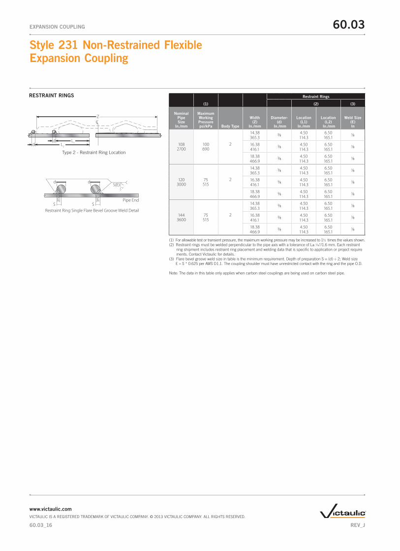
(1) For allowable test or transient pressure, the maximum working pressure may be increased to 11/2 times the values shown. (2) Restraint rings must be welded perpendicular to the pipe axis with a tolerance of L± 1/16"/1.6 mm. Each restraint ring shipment includes restraint ring placement and welding data that is specific to application or project require ments. Contact Victaulic for details. (3) Flare bevel groove weld size in table is the minimum requirement. Depth of preparation S = (d) ÷ 2; Weld size E ≈ S * 0.625 per AWS D1.1. The coupling shoulder must have unrestricted contact with the ring and the pipe O.D.
Note: The data in this table only applies when carbon steel couplings are being used on carbon steel pipe.
RESTRAINT RINGS
Type 2 - Restraint Ring Location
d L1
LC
L2d
Z
Pipe End
Restraint Ring Single Flare Bevel Groove Weld Detailfor Style 231/231S
S(E)d
ES
d
ES
60.03_13
Style 231 Non-Restrained Flexible Expansion Coupling
60.03EXPANSION COUPLING
www.victaulic.comVICTAULIC IS A REGISTERED TRADEMARK OF VICTAULIC COMPANY. © 2013 VICTAULIC COMPANY. ALL RIGHTS RESERVED.
REV_J

(1)
Restraint Rings
(2) (3)
Nominal Pipe Size
In./mm
Maximum Working Pressure psi/kPa Body Type
Width (Z)
In./mm
Diameter- (d)
In./mm
Location (L1)
In./mm
Location (L2)
In./mm
Weld Size (E) In
30750
100 690
2
14.38 1/4 4.50 6.25 3/32365.3 114.3 158.8
16.38 1/4 4.50 6.25 3/32416.1 114.3 158.8
18.38 1/4 4.50 6.25 3/32466.9 114.3 158.8
300 2065
2
14.38 1/4 4.50 6.25 3/32365.3 114.3 158.8
16.38 1/4 4.50 6.25 3/32416.1 114.3 158.8
18.38 1/4 4.50 6.25 3/32466.9 114.3 158.8
36900
75 515
2
14.38 3/8 4.50 6.50 1/8365.3 114.3 158.8
16.38 3/8 4.50 6.50 1/8416.1 114.3 158.8
18.38 3/8 4.50 6.50 1/8466.9 114.3 158.8
300 2065
2
14.38 3/8 4.50 6.50 1/8365.3 114.3 158.8
16.38 3/8 4.50 6.50 1/8416.1 114.3 158.8
18.38 3/8 4.50 6.50 1/8466.9 114.3 158.8
421050
50 345
2
14.38 3/8 4.50 6.50 1/8365.3 114.3 158.8
16.38 3/8 4.50 6.50 1/8416.1 114.3 158.8
18.38 3/8 4.50 6.50 1/8466.9 114.3 158.8
2501725
2
14.38 3/8 4.50 6.50 1/8365.3 114.3 158.8
16.38 3/8 4.50 6.50 1/8416.1 114.3 158.8
18.38 3/8 4.50 6.50 1/8466.9 114.3 158.8
481200
50 345
2
14.38 3/8 4.50 6.50 1/8365.3 114.3 158.8
16.38 3/8 4.50 6.50 1/8416.1 114.3 158.8
18.38 3/8 4.50 6.50 1/8466.9 114.3 158.8
250 1725
2
14.38 3/8 4.50 6.50 1/8365.3 114.3 158.8
16.38 3/8 4.50 6.50 1/8416.1 114.3 158.8
18.38 3/8 4.50 6.50 1/8466.9 114.3 158.8
(1) For allowable test or transient pressure, the maximum working pressure may be increased to 11/2 times the values shown. (2) Restraint rings must be welded perpendicular to the pipe axis with a tolerance of L± 1/16"/1.6 mm. Each restraint ring shipment includes restraint ring placement and welding data that is specific to application or project require ments. Contact Victaulic for details. (3) Flare bevel groove weld size in table is the minimum requirement. Depth of preparation S = (d) ÷ 2; Weld size E ≈ S * 0.625 per AWS D1.1. The coupling shoulder must have unrestricted contact with the ring and the pipe O.D.
Note: The data in this table only applies when carbon steel couplings are being used on carbon steel pipe.
RESTRAINT RINGS
Type 2 - Restraint Ring Location
d L1
LC
L2d
Z
Pipe End
Restraint Ring Single Flare Bevel Groove Weld Detailfor Style 231/231S
S(E)d
ES
d
ES
60.03_14
Style 231 Non-Restrained Flexible Expansion Coupling
60.03EXPANSION COUPLING
www.victaulic.comVICTAULIC IS A REGISTERED TRADEMARK OF VICTAULIC COMPANY. © 2013 VICTAULIC COMPANY. ALL RIGHTS RESERVED.
REV_J

(1)
Restraint Rings
(2) (3)
Nominal Pipe Size
In./mm
Maximum Working Pressure psi/kPa Body Type
Width (Z)
In./mm
Diameter- (d)
In./mm
Location (L1)
In./mm
Location (L2)
In./mm
Weld Size (E) In
54 1350
200 1375
2
14.38 3/8 4.50 6.50 1/8365.3 114.3 165.1
16.38 3/8 4.50 6.50 1/8416.1 114.3 165.1
18.38 3/8 4.50 6.50 1/8466.9 114.3 165.1
60 1500
200 1375
2
14.38 3/8 4.50 6.50 1/8365.3 114.3 165.1
16.38 3/8 4.50 6.50 1/8416.1 114.3 165.1
18.38 3/8 4.50 6.50 1/8466.9 114.3 165.1
66 1650
175 1200
2
14.38 3/8 4.50 6.50 1/8365.3 114.3 165.1
16.38 3/8 4.50 6.50 1/8416.1 114.3 165.1
18.38 3/8 4.50 6.50 1/8466.9 114.3 165.1
72 1800
175 1200
2
14.38 3/8 4.50 6.50 1/8365.3 114.3 165.1
16.38 3/8 4.50 6.50 1/8416.1 114.3 165.1
18.38 3/8 4.50 6.50 1/8466.9 114.3 165.1
78 1950
150 1035
2
14.38 3/8 4.50 6.50 1/8365.3 114.3 165.1
16.38 3/8 4.50 6.50 1/8416.1 114.3 165.1
18.38 3/8 4.50 6.50 1/8466.9 114.3 165.1
84 2100
150 1035
2
14.38 3/8 4.50 6.50 1/8365.3 114.3 165.1
16.38 3/8 4.50 6.50 1/8416.1 114.3 165.1
18.38 3/8 4.50 6.50 1/8466.9 114.3 165.1
90 2250
100 690
2
14.38 3/8 4.50 6.50 1/8365.3 114.3 165.1
16.38 3/8 4.50 6.50 1/8416.1 114.3 165.1
18.38 3/8 4.50 6.50 1/8466.9 114.3 165.1
96 2400
100 690
2
14.38 3/8 4.50 6.50 1/8365.3 114.3 165.1
16.38 3/8 4.50 6.50 1/8416.1 114.3 165.1
18.38 3/8 4.50 6.50 1/8466.9 114.3 165.1
(1) For allowable test or transient pressure, the maximum working pressure may be increased to 11/2 times the values shown. (2) Restraint rings must be welded perpendicular to the pipe axis with a tolerance of L± 1/16"/1.6 mm. Each restraint ring shipment includes restraint ring placement and welding data that is specific to application or project require ments. Contact Victaulic for details. (3) Flare bevel groove weld size in table is the minimum requirement. Depth of preparation S = (d) ÷ 2; Weld size E ≈ S * 0.625 per AWS D1.1. The coupling shoulder must have unrestricted contact with the ring and the pipe O.D.
Note: The data in this table only applies when carbon steel couplings are being used on carbon steel pipe.
RESTRAINT RINGS
Type 2 - Restraint Ring Location
d L1
LC
L2d
Z
Pipe End
Restraint Ring Single Flare Bevel Groove Weld Detailfor Style 231/231S
S(E)d
ES
d
ES
60.03_15
Style 231 Non-Restrained Flexible Expansion Coupling
60.03EXPANSION COUPLING
www.victaulic.comVICTAULIC IS A REGISTERED TRADEMARK OF VICTAULIC COMPANY. © 2013 VICTAULIC COMPANY. ALL RIGHTS RESERVED.
REV_J
(1)
Restraint Rings
(2) (3)
Nominal Pipe Size
In./mm
Maximum Working Pressure psi/kPa Body Type
Width (Z)
In./mm
Diameter- (d)
In./mm
Location (L1)
In./mm
Location (L2)
In./mm
Weld Size (E) In
108 2700
100 690
2
14.38 3/8 4.50 6.50 1/8365.3 114.3 165.1
16.38 3/8 4.50 6.50 1/8416.1 114.3 165.1
18.38 3/8 4.50 6.50 1/8466.9 114.3 165.1
120 3000
75 515
2
14.38 3/8 4.50 6.50 1/8365.3 114.3 165.1
16.38 3/8 4.50 6.50 1/8416.1 114.3 165.1
18.38 3/8 4.50 6.50 1/8466.9 114.3 165.1
144 3600
75 515
2
14.38 3/8 4.50 6.50 1/8365.3 114.3 165.1
16.38 3/8 4.50 6.50 1/8416.1 114.3 165.1
18.38 3/8 4.50 6.50 1/8466.9 114.3 165.1
(1) For allowable test or transient pressure, the maximum working pressure may be increased to 11/2 times the values shown. (2) Restraint rings must be welded perpendicular to the pipe axis with a tolerance of L± 1/16"/1.6 mm. Each restraint ring shipment includes restraint ring placement and welding data that is specific to application or project require ments. Contact Victaulic for details. (3) Flare bevel groove weld size in table is the minimum requirement. Depth of preparation S = (d) ÷ 2; Weld size E ≈ S * 0.625 per AWS D1.1. The coupling shoulder must have unrestricted contact with the ring and the pipe O.D.
Note: The data in this table only applies when carbon steel couplings are being used on carbon steel pipe.
RESTRAINT RINGS
Type 2 - Restraint Ring Location
d L1
LC
L2d
Z
Pipe End
Restraint Ring Single Flare Bevel Groove Weld Detailfor Style 231/231S
S(E)d
ES
d
ES
60.03_16
Style 231 Non-Restrained Flexible Expansion Coupling
60.03EXPANSION COUPLING
www.victaulic.comVICTAULIC IS A REGISTERED TRADEMARK OF VICTAULIC COMPANY. © 2013 VICTAULIC COMPANY. ALL RIGHTS RESERVED.
REV_J

CLOSURE TOOLS
MANUAL TOOL
HYDRAULIC TOOL
Manual Tools
• CTM-01: for use on 5" and 8" body widths • CTM-02: for use on 10" body widths for use on 12" body widths with thickness of 3/16" or less
Hydraulic Tools
• CTH-01*: for use on 12" body widths with thickness of 1/4" or greater for use on 14", 16" and 18" body widths • CTH-02: for use on all type 3 couplings • Hydraulic tool package comes standard with:
• one (1) tool head • one (1) hydraulic cylinder • one (1) hydraulic hose • one (1) hand pump
* A CTH-01 hydraulic closure tool can be used in applications where the CTM-02 manual closure tool is recommended.
Note: The closure tools listed above are designed specifically for Victaulic Style 230, 231, 232 and 233 couplings. If ordering custom product, contact Victaulic for appropriate tool selection.
60.03_17
Style 231 Non-Restrained Flexible Expansion Coupling
60.03EXPANSION COUPLING
www.victaulic.comVICTAULIC IS A REGISTERED TRADEMARK OF VICTAULIC COMPANY. © 2013 VICTAULIC COMPANY. ALL RIGHTS RESERVED.
REV_J

WARRANTY Refer to the Warranty section of the current Price List or contact Victaulic for details.
This product shall be manufactured by Victaulic or to Victaulic specifications. All products to be installed in accordance with current Victaulic installation/assembly instructions. Victaulic reserves the right to change product specifications, designs and standard equipment without notice and without incurring obligations.
NOTE
TESTING Victaulic Style 231 couplings are designed to allow for a 50 percent increase over the published max-imum working pressure for test and/or transient pressures. Due to the huge volume of air that can be involved in jobsite air testing and the nature of air or gas that is pressurized, jobsite air testing should be limited to 25 psi/175 kPa or less.
PRODUCT CONFIGURATOR
ENGINEERED PRODUCTS OPTIONS
For non-standard products the Victaulic Engineered Products group can assist with specialty joints designed to meet the specific size, pressure and temperature requirements of your system.
Class Style Inches^Actual Pipe O.D. *
Fraction Segments PaintRubber
CompoundPSI/kPaRating
BodyType
Ring and Pipe Material Movement †Hardware
C S – Carbon 1 – One2 – Two
0231 0015through0150
00 – 013 – /25 – ¼38 – /50 – ½63 – /75 – ¾88 – /
B – 50/345C – 75/515D – 100/690F – 150/1035G – 175/1200H – 200/1375J – 250/1725K – 300/2065
E – EPDMI – IsopreneL – SiliconeT – NitrileV – NeopreneO – Fluoro- elastomer
F – Fusion bonded epoxyP – Orange enamelT – Shop primerB – Liquid epoxyN – Fusion bonded nylonG – Galvanized0 – None
S –CarbonX –StainlessG –Galvanized
S – Carbon Steel Ring on Carbon Steel PipeD – Carbon Steel Ring on Ductile Iron PipeX- Stainless Steel Ring on Stainless Steel Pipe
D – 2.00"E – 3.00"F – 4.00"
C S 2 C E S S DP0231 50
^ Couplings are available in a range of nominal sizes from 16 – 144".* For actual pipe O.D. round down to the nearest /" to determine proper coupling size required. † Movement provided is dependent on size and body type and must correspond to allowable movements published in the product submittal.
0144
60.03
Style 231 Non-Restrained Flexible Expansion Coupling
60.03EXPANSION COUPLING
For complete contact information, visit www.victaulic.com60.03 3364 REV J UPDATED 08/2013VICTAULIC IS A REGISTERED TRADEMARK OF VICTAULIC COMPANY. © 2013 VICTAULIC COMPANY. ALL RIGHTS RESERVED.
Related Documents