Study Unit Diesel Engine Computer Systems

Welcome message from author
This document is posted to help you gain knowledge. Please leave a comment to let me know what you think about it! Share it to your friends and learn new things together.
Transcript

Study Unit
Diesel Engine Computer Systems
iii
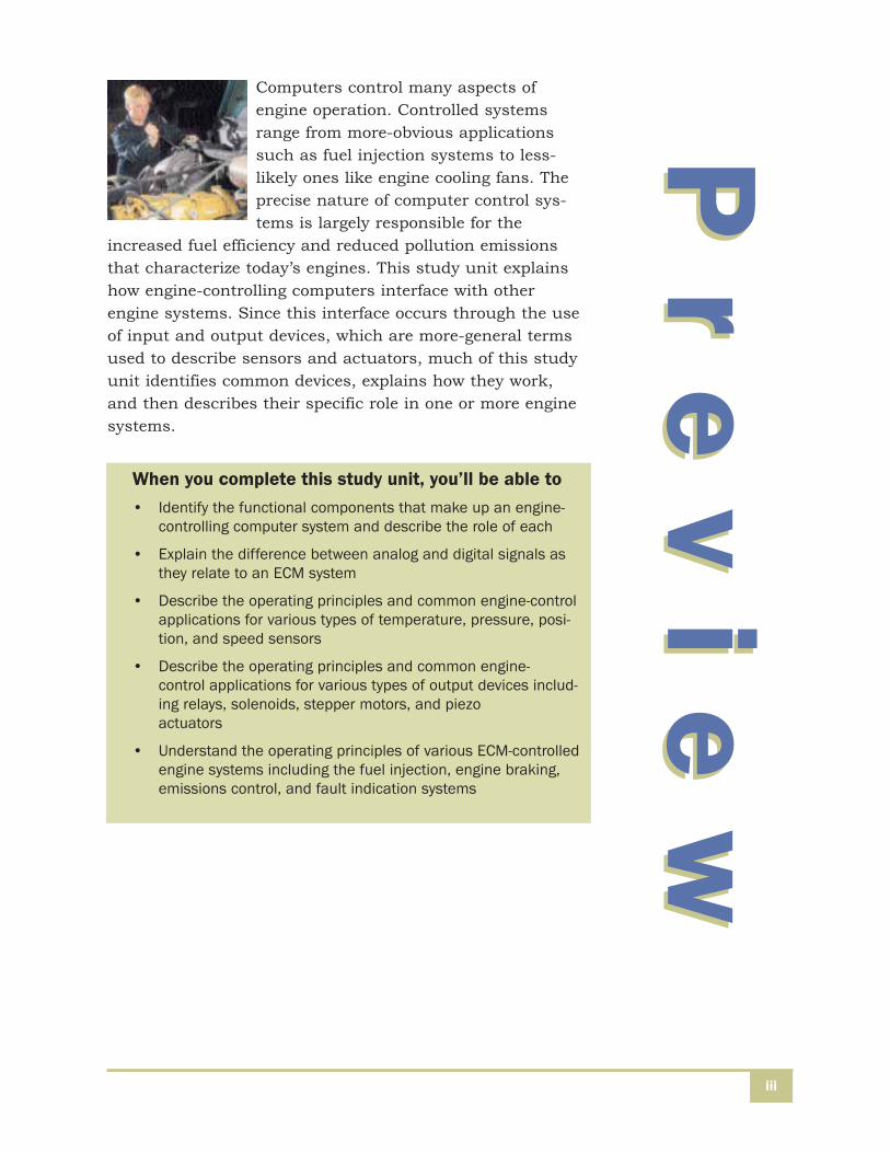
Computers control many aspects ofengine operation. Controlled systemsrange from more-obvious applicationssuch as fuel injection systems to less-likely ones like engine cooling fans. Theprecise nature of computer control sys-tems is largely responsible for the
increased fuel efficiency and reduced pollution emissionsthat characterize today’s engines. This study unit explainshow engine-controlling computers interface with otherengine systems. Since this interface occurs through the useof input and output devices, which are more-general termsused to describe sensors and actuators, much of this studyunit identifies common devices, explains how they work,and then describes their specific role in one or more enginesystems.
Pr
ev
ie
wP
re
vi
ew
When you complete this study unit, you’ll be able to • Identify the functional components that make up an engine-
controlling computer system and describe the role of each
• Explain the difference between analog and digital signals asthey relate to an ECM system
• Describe the operating principles and common engine-controlapplications for various types of temperature, pressure, posi-tion, and speed sensors
• Describe the operating principles and common engine-control applications for various types of output devices includ-ing relays, solenoids, stepper motors, and piezo actuators
• Understand the operating principles of various ECM-controlledengine systems including the fuel injection, engine braking,emissions control, and fault indication systems
v
COMPUTER SYSTEM BASICS 1
Basic Computer Operation 1Control Fundamentals 14
SENSORS 20
Temperature Sensors 20Pressure Sensors 26Position and Speed Sensors 31Specialized Sensors 38
OUTPUT DEVICES 41
Solenoids and Relays 41Stepper Motors 44Piezo-Actuated Injectors 45Common Applications of Output Devices 47Indicator Lights and Fault Codes 58
SELF-CHECK ANSWERS 63
Co
nt
en
ts
Co
nt
en
ts
1
COMPUTER SYSTEM BASICS
Like anything unfamiliar, an engine’s computer system mayseem strange and confusing at first. Yet, vehicle-computersystems can be easier to troubleshoot and repair than engineor electrical-system failures.
Today’s computers use state-of-the-art technology to controla vehicle’s fuel, ignition, emission, transmission, enginebrake, and service braking systems. Also, computers areused to control diagnostic, climate control, and many othersystems with which drivers interface.
Basic Computer Operation
Unlike human beings, computers have no true intelligence. Acomputer is only an electronic device that processes informa-tion very swiftly. For any given task, a computer requiresmuch more instruction than a person does. For example, get-ting a glass of water is a very simple task for most people. Incontrast, a computer-controlled robot would require millionsof instructions to get the same glass of water.
A computer is, however, a marvel in the speed at which itcan process information and instructions. Most computerscan process millions of instructions every minute. The speedwith which it processes information is what makes a comput-er ideal for controlling a vehicle’s operation. The functions ofthe computers found in our vehicles can be broken downinto three categories:
• Receiving data
• Processing data and/or storing
Diesel Engine Computer Systems

Diesel Engine Computer Systems
• Outputting signals
The computer in Figure 1 controls a very basic system. Here,an input device called a sensor sends a value to the computer.This value, in electronic terms, can be a voltage or digital num-ber. This input value tells the computer the condition of themonitored system. The computer compares the value receivedagainst a preprogrammed value in the computer’s memory andmakes a decision. The computer then converts this decisioninto an output signal that either controls an output device orreports information to a dashboard gauge, warning light, orother diagnostic system.
2
Sensor Computer
Output SignalInput Signal
Output Device
FIGURE 1—A computer system receives inputs from sensors and other devices, evaluatesand otherwise processes the input, then sends a signal to an output device.
A sensor measures a physical property (such as temperature) and converts thatmeasurement to an electrical signal. The voltage level of the signal emitted bythe sensor corresponds with the measured value. For instance, one type of tem-perature sensor represents the temperature to which it’s exposed by emitting asmall voltage (several millivolts) that’s proportional to the measured temperature.A type of pressure sensor measures fluid pressure, such as the pressure of oilinside the crankcase, then converts that measurement into a voltage level it sup-plies to the computer. The computer uses this voltage to generate the pressurereading displayed on the dashboard, illuminate a warning light when the level istoo low, and control output devices. Most vehicle sensors employ either a changein voltage or resistance to “report” to the computer what they observe while mon-itoring an engine system. You’ll learn much more about how various types ofsensors function later in this study unit.

Diesel Engine Computer Systems 3
Of course, a real-world engine- or vehicle-control computer ismuch more complex than the one shown in Figure 1. Anengine-control computer, often referred to as an electroniccontrol module (ECM) or by a similar name, receives data from and outputs signals related to many engine systemsincluding:
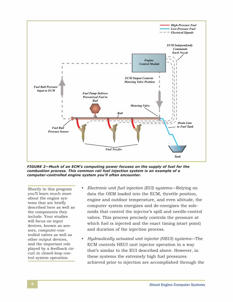
• Common rail fuel injection systems—These very commonECM-controlled fuel injection systems include a crank-shaft-driven fuel pump that provides pressurized fuel toa storage component known as the rail (Figure 2).Distribution lines transmit fuel from the rail to injectorsserving each cylinder. The ECM turns on fuel flow fromeach nozzle, either as part of the regular injectionprocess or, in some engines, to support the diesel-particulate filter washdown process. Very high fuel pres-sure in the rail is key to the successful operation ofthese systems. However, since the rail supplies fuel to allcylinders at a rate that varies dramatically with operat-ing conditions, and the incoming fuel supply comes froma pump that’s not electronically controlled, the ECMconstantly monitors data from a rail pressure sensor todetermine when rail fuel pressure drops below or risesabove the target value. When pressure exceeds theacceptable limit, the ECM adjusts a metering valve thatincreases the flow of fuel from the rail into a drain lineuntil the pressure sensor data indicates rail pressurehas fallen into the acceptable measurement range.Similarly, if pressure in the rail is too low, the ECMadjusts the metering valve to allow less fuel to flow fromthe rail into the drain line. When a controller, like theECM, adjusts a controlled device like a metering valvebased on the input from a sensor that’s monitoring theeffect of the adjustment, the control system is referred toas a closed-loop system.
Diesel Engine Computer Systems
• Electronic unit fuel injection (EUI) systems—Relying ondata the OEM loaded into the ECM, throttle position,engine and outdoor temperature, and even altitude, thecomputer system energizes and de-energizes the sole-noids that control the injector’s spill and needle-controlvalves. This process precisely controls the pressure atwhich fuel is injected and the exact timing (start point)and duration of the injection process.
• Hydraulically actuated unit injector (HEUI) systems—TheECM controls HEUI unit injector operation in a waythat’s similar to the EUI described above. However, inthese systems the extremely high fuel pressuresachieved prior to injection are accomplished through the
4
Engine Control Module
Fuel Rail Pressure Input to ECM
Fuel Rail Pressure Sensor
Fuel Pump DeliversPressurized Fuel to
RailMetering Valve
Drain Line to Fuel Tank
Tank
ECM Output Controls Metering Valve Position
ECM Independently CommandsEach Nozzle
High-Pressure FuelLow-Pressure FuelElectrical Signals
Rail
Fuel Nozzles
FIGURE 2—Much of an ECM’s computing power focuses on the supply of fuel for thecombustion process. This common rail fuel injection system is an example of a computer-controlled engine system you’ll often encounter.
Shortly in this programyou’ll learn much moreabout the engine sys-tems that are brieflydescribed here as well asthe components theyinclude. Your studieswill focus on inputdevices, known as sen-sors, computer-con-trolled valves as well asother output devices,and the important roleplayed by a feedback cir-cuit in closed-loop con-trol system operation.

Diesel Engine Computer Systems 5
use of a hydraulic pumping element. The pumping ele-ment’s pressurization of engine oil, monitored by theinjection control pressure (ICP) sensor, is electronicallycontrolled by an injection pressure regulator (IPR) whosespool is positioned by the ECM. Throughout thisprocess, the ECM receives and processes pressure-measurement data from the ICP sensor, which it uses to determine whether or not to change the injection pressure.
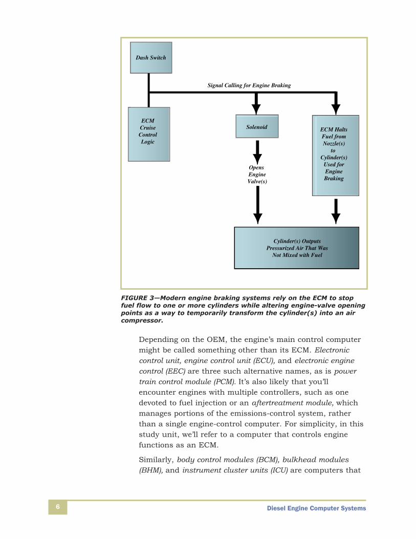
• Engine braking systems—Often referred to as jakebrakes, these systems help reduce vehicle speed withoutthe use of wheel brakes. As you’ll shortly read in moredetail, this is accomplished by adjusting the valve open-ing and fuel-injection behavior of one or more cylinders(Figure 3). The intention of these adjustments is to usepower from the drive wheels to turn the cylinder(s) into acompressor. The ECM is responsible for halting fuelinjection to the cylinder(s) involved in the engine brakingprocess, and for changing the position of the cylindervalves to facilitate the power-absorbing compressionprocess.
• Exhaust gas recirculation (EGR) systems—One of several computer-controlled systems whose purpose islimiting pollution levels. In this case, the pollutant isknown as NOx (oxides of nitrogen). The EGR systemincludes an ECM-controlled valve, which routes some ofthe exhaust gas to mix with intake air, reducing theamount of oxygen available for combustion. As you’lllearn in this study unit, ever-expanding computer con-trol capabilities have played a tremendous role in reduc-ing vehicle emissions.
Diesel Engine Computer Systems6
Depending on the OEM, the engine’s main control computermight be called something other than its ECM. Electronic control unit, engine control unit (ECU), and electronic enginecontrol (EEC) are three such alternative names, as is powertrain control module (PCM). It’s also likely that you’llencounter engines with multiple controllers, such as onedevoted to fuel injection or an aftertreatment module, whichmanages portions of the emissions-control system, ratherthan a single engine-control computer. For simplicity, in thisstudy unit, we’ll refer to a computer that controls enginefunctions as an ECM.
Similarly, body control modules (BCM), bulkhead modules(BHM), and instrument cluster units (ICU) are computers that
Opens EngineValve(s)
Dash Switch
ECMCruiseControlLogic
Solenoid
Cylinder(s) OutputsPressurized Air That Was
Not Mixed with Fuel
ECM HaltsFuel fromNozzle(s)
to Cylinder(s)
Used forEngineBraking
Signal Calling for Engine Braking
FIGURE 3—Modern engine braking systems rely on the ECM to stopfuel flow to one or more cylinders while altering engine-valve openingpoints as a way to temporarily transform the cylinder(s) into an aircompressor.

Diesel Engine Computer Systems 7
monitor and issue output signals related to other vehicle systems like the cruise control, climate control equipment,and the instrument panel. Throughout this study unit you’lllearn more about how sensors, computers, and output deviceswork together to optimize engine and vehicle performance.
Data Received by the Computer
It’s best to think of data as information. This information canbe as simple to understand as the position of a switch, suchas whether or not the cruise-control switch is in the on or offposition. More often, the data received by the computerarrives in the form of an electronic signal from a sensor.
The data received by the computer can be grouped into oneof two categories, analog and digital.
A digital signal is one that varies between one of two states,such as the positions of a switch that’s either on or off. Inthe technical terms applied to computers, digital signals areidentified as being either a 0 or a 1. Modern computers per-form their operations on digital data.
An analog signal is one that varies within an acceptablerange. For instance, a sensor’s evaluation of oil temperaturemay be reported as a voltage level that falls somewherebetween 0 and 5 volts. In this case, the lowest expected tem-perature might be represented by the temperature sensorwith an analog signal equal to 0 volts. Meanwhile, a 5-voltsignal would indicate the temperature sensor is experiencingthe highest temperature it’s designed to evaluate. In an ana-log sensor, each voltage level between these two extremescorresponds to a different temperature level. Analog datasent to a computer is converted to digital data before thecomputer attempts to evaluate it.
In Figure 4, you can see examples of analog and digital sig-nals. In Figure 4A, the voltage of an analog signal varies withtime. This varying signal might represent a changing temper-ature or pressure level. In Figure 4B, the voltage level of adigital signal, which varies between two predefined unique ordiscrete values, appears as pulses of voltage. These pulsesmight represent the position of an on/off solenoid (which is

Diesel Engine Computer Systems
either energized or de-energized). These pulses can also rep-resent temperature, such as the voltage emitted by an analogsensor. In this case, the analog signal goes through an ana-log-to-digital conversion process in the computer’s inputmodule. The result of this conversion process is that the analog signal is converted into a digital number that can beevaluated by the computer.
Data Is Processed by the Computer
Once the computer receives data, which once again can bethought of as information, it goes to work evaluating it. Thisevaluation may involve simply comparing the received data(such as a specific pressure level) with a predefined mini-mum acceptable value or it may involve very complex calcu-lations involving dozens of measured values and mathemati-cal formulas. Whether relatively simple or extremely complex,these evaluating tasks are carried out in the computer’s central processing unit, or CPU.
While a computer’s CPU can be thought of as its brain, itcan’t control a system on its own. First of all, it relies on aset of instructions to tell it what to do with the data itreceives. Often, these instructions (which are commonlyreferred to as software or as a computer program) tell theCPU to compare the incoming data with predeterminedacceptable limits, such as a minimum and maximum acceptable engine coolant temperature, which are stored in
8
Analog Signal(A)
Volta
ge
Digital Signal(B)
Volta
ge
FIGURE 4—The voltagelevel of the analog signalin A varies continuouslywhile the digital signal inB is made of pulses thatsimply switch on and off.

Diesel Engine Computer Systems 9
memory. The CPU relies on other computer components tostore data, instructions, and even these predetermined limits. You can think of a computer’s data-storage features as belonging to two groups: storage locations that can bewritten over and altered and locations that remain either permanently unchanged or at least are unchanged until significant actions are taken (Figure 5). You’ll hear the typeof memory that’s quickly overwritten or modified referred toas volatile memory. In most cases, the contents of volatilememory are erased each time the truck’s key is turned off.
Input Module
Output Module
Nonvolatile Memory
Volatile Memory
Software(Instructions)
CPU
FIGURE 5—A computer can be thought of as a collection of subsystems, each performingone or more tasks.
Diesel Engine Computer Systems10
Following is a summary of each term you’re likely toencounter that relates to computer memory:
• RAM, or random access memory, is a type of volatilememory, since information stored in RAM is erasedwhen the ignition key is switched off. RAM is whereincoming information is held, updated, and evaluated asthe vehicle operates. The evaluation of the informationheld in RAM is carried out based on instructions programmed into the computer’s ROM. RAM keeps infor-mation about driver inputs, barometric pressure, tem-perature of the engine or air, and speed of the vehicle.
• ROM, or read-only memory, isn’t intended to be overwritten. For this reason, it’s known as nonvolatilememory. This type of memory contains the basic rulesthat determine the operation of various vehicle systemssuch as the fuel injection. It also contains OEM-deter-mined acceptable limits for various engine parameters(like coolant temperature) above which the ECM issues awarning message.
• PROM, or programmable read-only memory, is typicallyused for information or programs relating to an engine’sspecific installation (when one engine family is found ina range of different vehicle models). The electronicallyerasable variety (EEPROM) is relatively easy to accessand modify, provided you have the applicable password.This memory contains data that’s likely to be changed bya maintenance technician (like tire measurement) oraccessed in the course of repairing a vehicle. It’s alsowhere the ECM stores fault codes and related data.
• Flash memory serves the same basic purpose as EEP-ROM, except that the flash memory storage device is oneto or from which data is transferred in large chunks,rather than in smaller units known as bytes. Data trans-fers to or from these devices more quickly than is thecase with EEPROM memory.
As you’ve already read, while data supplied to the computermay arrive in one of two formats, as an analog or a digitalsignal, the computer’s evaluation work requires that the
Diesel Engine Computer Systems 11
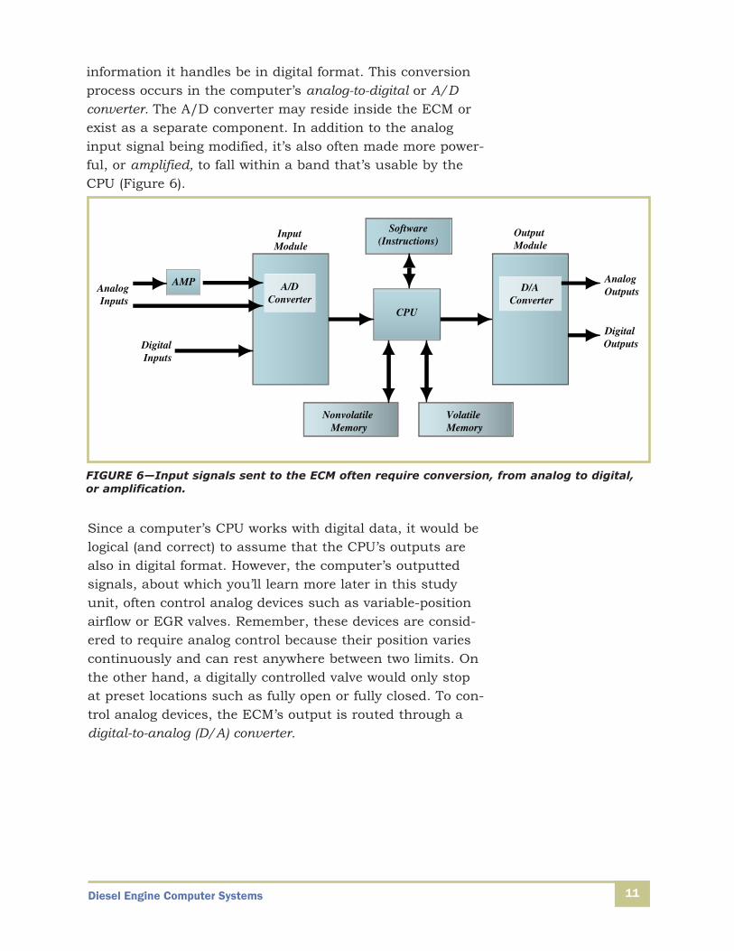
information it handles be in digital format. This conversionprocess occurs in the computer’s analog-to-digital or A/D converter. The A/D converter may reside inside the ECM orexist as a separate component. In addition to the analoginput signal being modified, it’s also often made more power-ful, or amplified, to fall within a band that’s usable by theCPU (Figure 6).
CPU
Input Module
Output Module
Nonvolatile Memory
Volatile Memory
Software(Instructions)
D/A Converter
Analog Outputs
Digital OutputsDigital
Inputs
AMP A/DConverter
Analog Inputs
FIGURE 6—Input signals sent to the ECM often require conversion, from analog to digital,or amplification.
Since a computer’s CPU works with digital data, it would belogical (and correct) to assume that the CPU’s outputs arealso in digital format. However, the computer’s outputtedsignals, about which you’ll learn more later in this studyunit, often control analog devices such as variable-positionairflow or EGR valves. Remember, these devices are consid-ered to require analog control because their position variescontinuously and can rest anywhere between two limits. Onthe other hand, a digitally controlled valve would only stopat preset locations such as fully open or fully closed. To con-trol analog devices, the ECM’s output is routed through adigital-to-analog (D/A) converter.

Diesel Engine Computer Systems12
The Computer’s Output
As a result of the CPU’s work, the ECM outputs signals thatmight be used to turn on fuel injectors for a specified periodof time, position the EGR valve, cause an electric motor torotate, or illuminate a dashboard warning light. The type ofsignal that ultimately arrives at the computer-controlled out-put device depends on the device’s operating characteristic.
One simple method of digital control is the on-off method.Here, the computer simply produces an output voltage, at aspecific level, to turn the device on. Similarly, this type ofoutput device can be turned off when the computer removesthe voltage. This type of on/off control can be thought ofoccurring with a constant voltage that’s on or off for a longperiod of time or with a single electrical pulse, a voltage levelthat’s emitted for a fraction of a second.
Other output devices are controlled through a series of multi-ple pulses. The use of pulse signals to control a device isoften called pulse-width modulation (PWM). The computerchanges pulse width, which equates to the amount of timethe electrical signal rests at its nonzero level, to increase ordecrease the operating speed of the device being controlled. APWM signal is shown in Figure 7. As the computer varies theoutput signal from wide to narrow pulses, the output device’smotion changes from full speed to a very slow speed. If thecomputer removes the output pulses entirely, the outputdevice is turned off.
High-SpeedOperation
Low-SpeedOperation
FIGURE 7—A wider pulse powers the output device for a longerperiod of time, resulting in a higher-speed or longer-durationoperation.

Diesel Engine Computer Systems 13
A computer can also control an output device by changingthe number of pulses sent to the output device each second.An example of this method is shown in Figure 8. When thepulses sent to the output device are tightly packed together,the output device spins faster. As the space, which equatesto time, between pulses widens, the output device begins toslow. When the pulses stop, the output device turns off.
High-SpeedOperation
Low-SpeedOperation
FIGURE 8—A computer can change the speed of a controlled output device by varying the number of pulses sent to the device over a period of time.
As you’ve already learned, many digital signals are based onanalog voltages. Analog voltages that originate at an inputdevice are converted to digital signals within the computer or sensor so that the computer can handle the information.Similarly, many output devices can only be controlled byanalog signals. The computer converts the digital informationto an analog signal for output to the analog device. A typicalexample of digital-to-analog signal conversion appears inFigure 9.

Diesel Engine Computer Systems14
Analog Signal
Analog Signal
Input ModuleOutput Module
MotorSensor
CPU
Digital Signals Digital Signals
Computer
FIGURE 9—Just as an analog input signal must be converted to a digital signal before it’sevaluated by a computer, the computer’s digital output signal can also be converted to ananalog output when controlling analog output devices.
Control Fundamentals
While many controlled vehicle systems are linked in one ormore ways, it’s easier to begin your study of control systemsby thinking of each vehicle system as if it’s independentlycontrolled.
Control Loops
To properly control the emissions system or any other vehiclesystem, the computer uses control loops. Control loops aresimply signal paths through which input devices, computers,and output devices communicate.
A simple example of a control loop can be found in mosthomes. The wall thermostat that controls the heating systemand sometimes the air conditioner works in the followingway:
1. A human or a temperature-scheduling program (in thecase of a programmable thermostat) sets a desired tem-perature. This set-point temperature directly representsthe heating system’s desired output while the actual tem-perature reading on the face of the thermostat repre-sents the measured output.

Diesel Engine Computer Systems 15
2. A temperature-sensitive spring in the thermostat con-tracts when the air around it becomes too cold and closes a set of contacts. The temperature-sensitivespring (or electronic temperature sensor, in the case of adigital device) serves as the system’s sensor.
3. The closing contacts act as the system’s controller, send-ing a signal to the furnace and blower motor, turning thefurnace on, and producing the heated air that warms thehouse.
4. When the house is warm enough, the thermostat springexpands, opening the set of contacts.
5. Since the contacts are open, the thermostat continuesits function as the system’s controller by stopping thesignal it had been sending to the motor. This switchesthe furnace and blower motor off.
6. When the house cools off again, the air around the ther-mostat becomes too cold and the cycle repeats.
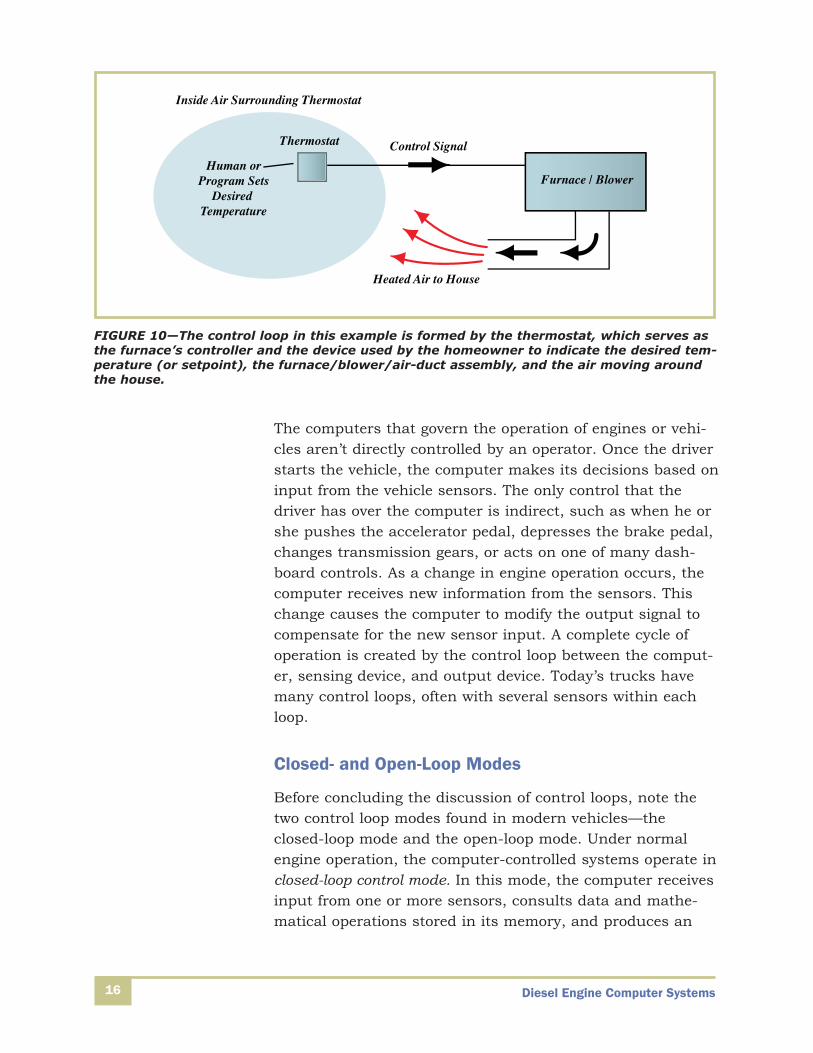
As you can see in Figure 10, the system described above rep-resents a control loop, and the controlled process is the addi-tion of heat to the air inside the house. The thermostat’stemperature-sensing element is a sensor, which sends aninput signal to the thermostat. The thermostat, serving asthe controller, outputs a signal to the furnace’s heater andblower motor circuits, turning them on when the interiortemperature is low enough to call for heat.
The operation of any computer is itself a control loop. Thecomputer serves as a controller, receiving an input and pro-ducing an output. On a laptop or tablet, the input is provid-ed when the operator presses a key on the keyboard or tapsan on-screen command key; the output might be a visiblechange in the device’s display screen. Notice that the laptopor tablet (both types of computers) requires a person to takeaction before the control-loop operation starts.
Diesel Engine Computer Systems
The computers that govern the operation of engines or vehi-cles aren’t directly controlled by an operator. Once the driverstarts the vehicle, the computer makes its decisions based oninput from the vehicle sensors. The only control that thedriver has over the computer is indirect, such as when he orshe pushes the accelerator pedal, depresses the brake pedal,changes transmission gears, or acts on one of many dash-board controls. As a change in engine operation occurs, thecomputer receives new information from the sensors. Thischange causes the computer to modify the output signal tocompensate for the new sensor input. A complete cycle ofoperation is created by the control loop between the comput-er, sensing device, and output device. Today’s trucks havemany control loops, often with several sensors within eachloop.
Closed- and Open-Loop Modes
Before concluding the discussion of control loops, note thetwo control loop modes found in modern vehicles—theclosed-loop mode and the open-loop mode. Under normalengine operation, the computer-controlled systems operate inclosed-loop control mode. In this mode, the computer receivesinput from one or more sensors, consults data and mathe-matical operations stored in its memory, and produces an
16
Furnace / BlowerHuman or
Program SetsDesired
Temperature
Inside Air Surrounding Thermostat
Thermostat
Heated Air to House
Control Signal
FIGURE 10—The control loop in this example is formed by the thermostat, which serves asthe furnace’s controller and the device used by the homeowner to indicate the desired tem-perature (or setpoint), the furnace/blower/air-duct assembly, and the air moving aroundthe house.
Diesel Engine Computer Systems 17
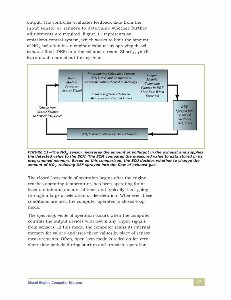
output. The controller evaluates feedback data from theinput sensor or sensors to determine whether furtheradjustments are required. Figure 11 represents an emissions-control system, which works to limit the amountof NOx pollution in an engine’s exhaust by spraying dieselexhaust fluid (DEF) into the exhaust stream. Shortly, you’lllearn much more about this system.
Input Module
ProcessesSensor Signal
Output Module
CommandsChange in DEFFlow Rate When
Error = 0
Programming Calculates CurrentNO Levels and Compares to
Desirable Values (Stored in Memory)x
Error = Difference between Measured and Desired Values
NO Sensor Evaluates Exhaust Samplex
DEF Sprayed into
ExhaustReduces
NO Levelx
Voltage fromSensor Relates
to Sensed NO Levelx
FIGURE 11—The NOx sensor measures the amount of pollutant in the exhaust and suppliesthe detected value to the ECM. The ECM compares the measured value to data stored in itsprogrammed memory. Based on this comparison, the ECU decides whether to change theamount of NOx-reducing DEF sprayed into the flow of exhaust gas.
The closed-loop mode of operation begins after the enginereaches operating temperature, has been operating for atleast a minimum amount of time, and typically, isn’t goingthrough a large acceleration or deceleration. Whenever theseconditions are met, the computer operates in closed-loopmode.
The open-loop mode of operation occurs when the computercontrols the output devices with few, if any, input signalsfrom sensors. In this mode, the computer scans its internalmemory for values and uses these values in place of sensormeasurements. Often, open-loop mode is relied on for veryshort time periods during startup and transient operation.

Diesel Engine Computer Systems18
Sensor failure can also cause a computer to operate in open-loop or, as it’s often called, limp-in mode. If a sensor’s valueis lost, or if it’s far out of range, then the computer enters theopen-loop mode. When sensor failure occurs, the computersystem’s diagnostic program normally sets a diagnostic trouble code (DTC) in memory, and illuminates a dashboardwarning light. As you know, the trouble code will aid you introubleshooting the source of the sensor failure.

Diesel Engine Computer Systems 19
Self-Check 1At the end of each section of Diesel Engine Computer Systems, you’ll be asked to pauseand check your understanding of what you’ve just read by completing a “Self-Check” exer-cise. Writing the answers to these questions will help you to review what you’ve studiedso far. Please complete Self-Check 1 now.
Complete the following statements with the correct answer.
1. True or False? The functions performed by vehicle computers include receiving data, process-ing data, and analyzing data.
2. A pressure sensor measures a fluid’s pressure level and converts that measurement to a spe-cific ________.
3. True or False? The ECM uses OEM data, specific to the vehicle in which the engine is installed,while controlling an electronic unit fuel injection system.
4. The _______ system adjusts cylinder valve opening points and fuel-injection system behaviorto slow the vehicle without relying on the wheel brakes.
5. True or False? NOx is a pollutant, found in engine emissions, which is partially controlledthrough the use of an exhaust gas recirculation system.
6. In engine computer control systems, a(n) ______ signal is one whose amplitude can fall any-where within a predetermined acceptable range.
7. True or False? Digital input is required by a CPU, while CPU output is always in the form of adigital signal that’s unable to be converted to an analog signal.
8. An output device that operates in only an on or off state, is most likely controlled by the ECMwith a _______ output signal.
9. During normal engine operation, the computer-controlled systems perform in ______ controlmode.
Check your answers with those on page 63.

Diesel Engine Computer Systems20
SENSORSRight now, you’re using at least one of your five senses:you’re relying on your sense of sight to read these words. Theinput your sight provides to your brain is necessary for youto understand the meaning of the words on this page. Likeyour brain, a computer needs information to make decisions.That’s why proper sensor operation is vital to the ECM’s abili-ty to control a vehicle’s engine and other systems.
As you’ve already learned, a sensor is a device thatmeasures a physical property, then converts that measure-ment into an electrical signal. You’ll find input sensorsmounted throughout a modern truck including on the body,engine, transmission, and brake systems. These sensorsmonitor position, motion, temperature, chemical content, flowrate, and pressure.
This part of your study unit introduces several types of sen-sors followed by several examples of how each type is typical-ly used in a truck. For instance, after learning about eachtype of temperature sensor, you’ll study various applicationsand the role the temperature sensors play in controlling amodern diesel engine. However, a few of the sensorsdescribed won’t apply to all engines (especially older ones).Also, it’s common that some sensors are given differentnames by different OEMs, even though they serve the samebasic function in each installation.
Temperature Sensors
The devices used to sense temperature in a vehicle are ther-mistors, thermocouples, or RTDs. A thermistor is a variable-resistance device made of a material whose internal resist-ance changes with differences in temperature. Thermocouplesincorporate two dissimilar metals joined together only at theirends. An RTD, or resistance temperature detector, incorpo-rates a thin wire whose electrical resistance changes withchanges in temperature.

Diesel Engine Computer Systems 21
Thermistor Sensors
This variable resistance sensor receives a reference voltagesignal from the ECM, which typically measures 5 VDC(Figure 12). Since the sensor is wired in series with theECM’s circuit, it returns a voltage that’s different from thereference level. Depending on the type of thermistor, resist-ance can either increase or decrease with an increase in tem-perature. Because the system designer knows how the resist-ance of a particular type of thermistor varies with tempera-ture, the ECM is programmed to interpret the change in volt-age as a specific temperature. One disadvantage of a ther-mistor-type sensor is that it delivers precise readings over arelatively narrow range of temperatures.
Volt-Meter
VoltageMeasurementto the ECM
5-Volt Reference
Fixed Resistor
ECM
Signal Wire
Thermister
Ground
Signal Wire
Voltage
5V
Cold Hot
NormalRange
OV
Temperature
FIGURE 12—As the thermistor’s resistance varies with temperaturewhile the reference voltage remains constant at 5 VDC, the ECM-monitored voltage also varies. Notice that the fixed resistor and volt-meter represented in this diagram are actually just part of the ECM’ssignal-processing capabilities.
Diesel Engine Computer Systems22
Thermocouple Sensors
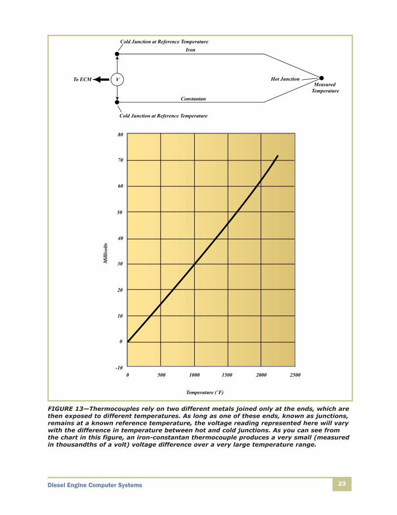
A thermocouple is made from two different metallic conduc-tors, joined together at each end but otherwise insulated fromeach other. The different or dissimilar metals in the type ofthermocouples you’ll encounter are most often iron and constantan, an alloy of copper and nickel (Figure 13). Thethermocouple produces a very small voltage whenever thetemperature at one of the joined ends, known as a junction ornode, differs from the temperature at the other junction. In apractical application, the hot junction is located where tem-perature must be measured while the other end, the referenceor cold junction, is maintained at a known temperature.Voltage measured at the reference junction varies withchanges in the measured temperature at the hot junction.One key benefit of using a thermocouple sensing device is itsability to withstand very high temperatures. This makes ther-mocouples popular for exhaust manifold and aftertreatmentsystem applications.
One practical disadvantage of thermocouple sensors comesfrom the fact that the level of voltage produced relates direct-ly to temperature at the point where the dissimilar metalsjoin. This means that a location where the sensing wires arespliced or allowed to make contact due to insulation failurebecomes an unintentional temperature-sensing junction. Forthis reason, damage to a thermocouple wire usually requiresreplacement of the entire sensing assembly (wire, nodes, endconnector, etc.) as a unit.
Diesel Engine Computer Systems 23
Iron
Hot JunctionMeasured
TemperatureConstantan
Cold Junction at Reference Temperature
To ECM V
Cold Junction at Reference Temperature
80
70
60
50
40
30
20
10
0
-100 500 1000 1500 2000 2500
Temperature (˚F)
Mill
ivol
ts
FIGURE 13—Thermocouples rely on two different metals joined only at the ends, which arethen exposed to different temperatures. As long as one of these ends, known as junctions,remains at a known reference temperature, the voltage reading represented here will varywith the difference in temperature between hot and cold junctions. As you can see fromthe chart in this figure, an iron-constantan thermocouple produces a very small (measuredin thousandths of a volt) voltage difference over a very large temperature range.

Diesel Engine Computer Systems24
RTD Sensors
Resistance temperature detectors rely on a thin metal wire’spredictable change in electrical resistance, which occurs whenthe wire’s temperature changes (Figure 14). RTDs are used inrelatively high-temperature locations since they function up toabout 1150°F. Unlike a thermistor, an RTD can precisely eval-uate changes over a wide range of temperatures.
Protective Covering
Wire
Insulating Coil Form
To ECM
FIGURE 14—The thin coiled wire’s resistance changes, in a very predictable way, withchanges in temperature. ECM circuitry applies a reference voltage to the RTD, much as itdoes to a thermistor, then monitors the voltage change across an internal resistance. Thisinternally monitored voltage change allows the ECM to determine how much the RTD’sresistance changed due to increasing or decreasing temperature.
Diesel Engine Computer Systems 25
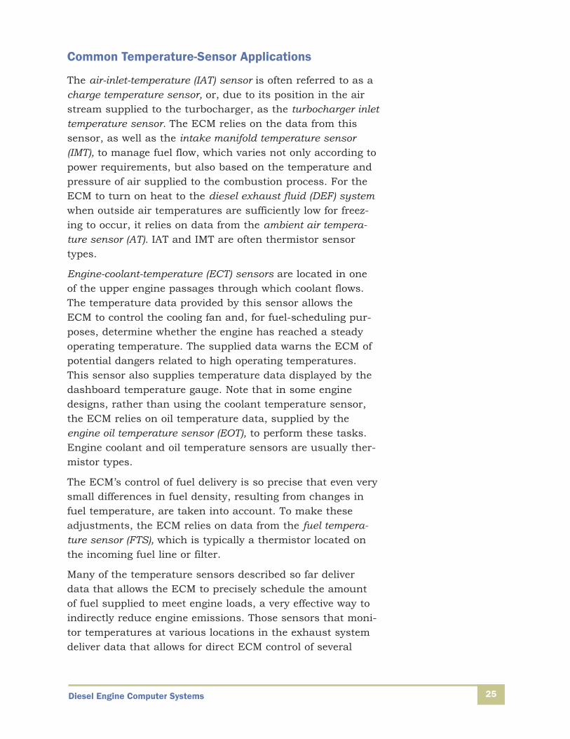
Common Temperature-Sensor Applications
The air-inlet-temperature (IAT) sensor is often referred to as acharge temperature sensor, or, due to its position in the airstream supplied to the turbocharger, as the turbocharger inlettemperature sensor. The ECM relies on the data from thissensor, as well as the intake manifold temperature sensor(IMT), to manage fuel flow, which varies not only according topower requirements, but also based on the temperature andpressure of air supplied to the combustion process. For theECM to turn on heat to the diesel exhaust fluid (DEF) systemwhen outside air temperatures are sufficiently low for freez-ing to occur, it relies on data from the ambient air tempera-ture sensor (AT). IAT and IMT are often thermistor sensortypes.
Engine-coolant-temperature (ECT) sensors are located in oneof the upper engine passages through which coolant flows.The temperature data provided by this sensor allows theECM to control the cooling fan and, for fuel-scheduling pur-poses, determine whether the engine has reached a steadyoperating temperature. The supplied data warns the ECM ofpotential dangers related to high operating temperatures.This sensor also supplies temperature data displayed by thedashboard temperature gauge. Note that in some enginedesigns, rather than using the coolant temperature sensor,the ECM relies on oil temperature data, supplied by theengine oil temperature sensor (EOT), to perform these tasks.Engine coolant and oil temperature sensors are usually ther-mistor types.
The ECM’s control of fuel delivery is so precise that even verysmall differences in fuel density, resulting from changes infuel temperature, are taken into account. To make theseadjustments, the ECM relies on data from the fuel tempera-ture sensor (FTS), which is typically a thermistor located onthe incoming fuel line or filter.
Many of the temperature sensors described so far deliverdata that allows the ECM to precisely schedule the amountof fuel supplied to meet engine loads, a very effective way toindirectly reduce engine emissions. Those sensors that moni-tor temperatures at various locations in the exhaust systemdeliver data that allows for direct ECM control of several
Diesel Engine Computer Systems
emissions-reducing systems. As you’re probably aware, theEGR system recirculates exhaust gas back into the cylinderas a way to reduce oxygen available for the combustionprocess and, therefore, reduce the emission of NOx pollu-tants. You’ll learn more about computer control of the EGRsystem later in this study unit.
The EGR exhaust temperature sensor (EGRT), collects data onthe temperature of the exhaust gas and is typically locatednear the outlet of the EGR cooler. The ECM uses this temper-ature data to adjust the EGR valve and the variable geometryturbocharger (VGT).
The diesel particulate filter is an aftertreatment system thatreduces soot from the engine exhaust by collecting it in filterelements, then regenerating the filter by burning off the col-lected material. The process of burning off the collected sootsometimes relies on the application of diesel fuel to the filter.Current state-of-the-art systems incorporate three exhaust-gas temperature sensors (EGT1 through EGT3) at various loca-tions within this system. The ECM relies on the data theysupply to determine the need for the filter regeneration cycleand control delivery of fuel to the aftertreatment system’sdiesel particulate filter. These temperature sensors also sup-ply data used by the ECM when adjusting turbochargergeometry and EGR valve position. Temperature sensors in theexhaust-aftertreatment and EGR systems can be either ther-mocouple or RTD types.
Pressure Sensors
Pressure sensors are an important part of many ECM controlloops. Pressure sensors monitor ambient-air and intake-manifold pressures to help the ECM gauge engine load at anytime, ensure engine safety by monitoring oil pressure, andcontinuously evaluate the operation of various emission-control systems. Most pressure sensors are variable-capacitance types while some incorporate strain gauges.
Variable-Capacitance Sensors
Earlier in your training program, you learned that a capacitoris a current-storing device made up of two plates separated
26
Diesel Engine Computer Systems 27
by some distance. Filling this plate-to-plate distance is anonconductive material known as a dielectric, which is some-times nothing more than air. One of the capacitor’s platesstores electrical charge until sufficiently loaded to discharge,allowing the built-up charge to move across the dielectric tothe second plate. The rate at which the capacitor builds ordischarges electrical charge is a measure of its capacitance.One way to vary the capacitance (and therefore dischargerate) of a capacitor is to change the distance between its twoplates. If one of a capacitor’s plates is attached to a mem-brane that flexes when exposed to changes in pressure, theplate-to-plate distance and, therefore, capacitance alsochanges. When processed by the right circuitry, this chang-ing capacitance can be transformed into a change in voltage,which is of more use to the ECM.
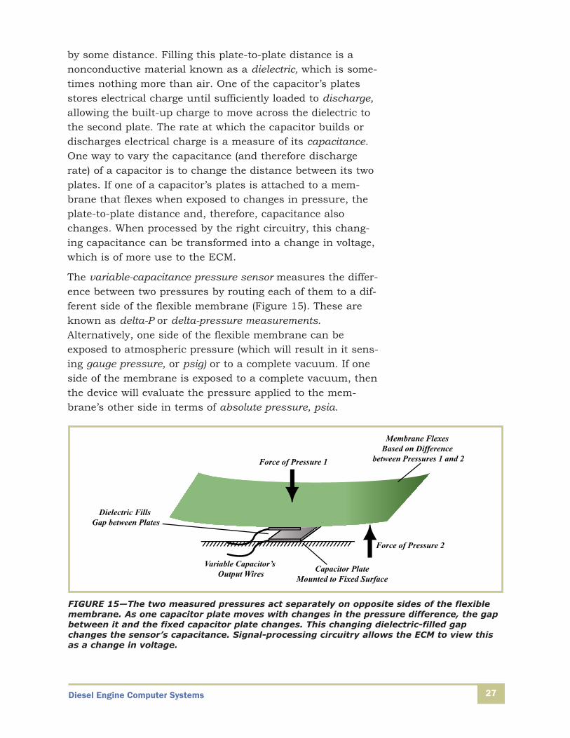
The variable-capacitance pressure sensor measures the differ-ence between two pressures by routing each of them to a dif-ferent side of the flexible membrane (Figure 15). These areknown as delta-P or delta-pressure measurements.Alternatively, one side of the flexible membrane can beexposed to atmospheric pressure (which will result in it sens-ing gauge pressure, or psig) or to a complete vacuum. If oneside of the membrane is exposed to a complete vacuum, thenthe device will evaluate the pressure applied to the mem-brane’s other side in terms of absolute pressure, psia.
Force of Pressure 2
Variable Capacitor’s Output Wires
Dielectric Fills Gap between Plates
Capacitor PlateMounted to Fixed Surface
Force of Pressure 1
Membrane Flexes Based on Difference
between Pressures 1 and 2
FIGURE 15—The two measured pressures act separately on opposite sides of the flexiblemembrane. As one capacitor plate moves with changes in the pressure difference, the gapbetween it and the fixed capacitor plate changes. This changing dielectric-filled gapchanges the sensor’s capacitance. Signal-processing circuitry allows the ECM to view thisas a change in voltage.
Diesel Engine Computer Systems28
Strain-Gauge Pressure Sensors
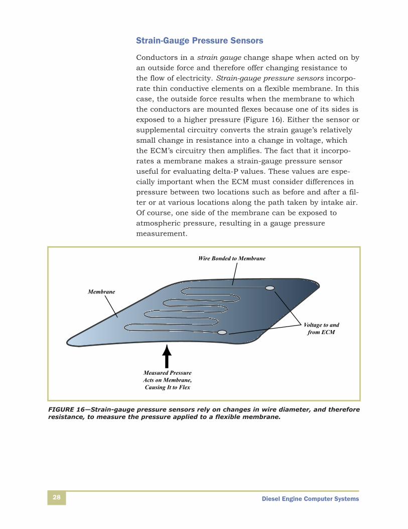
Conductors in a strain gauge change shape when acted on byan outside force and therefore offer changing resistance tothe flow of electricity. Strain-gauge pressure sensors incorpo-rate thin conductive elements on a flexible membrane. In thiscase, the outside force results when the membrane to whichthe conductors are mounted flexes because one of its sides isexposed to a higher pressure (Figure 16). Either the sensor orsupplemental circuitry converts the strain gauge’s relativelysmall change in resistance into a change in voltage, whichthe ECM’s circuitry then amplifies. The fact that it incorpo-rates a membrane makes a strain-gauge pressure sensoruseful for evaluating delta-P values. These values are espe-cially important when the ECM must consider differences inpressure between two locations such as before and after a fil-ter or at various locations along the path taken by intake air.Of course, one side of the membrane can be exposed toatmospheric pressure, resulting in a gauge pressure measurement.
Measured PressureActs on Membrane,Causing It to Flex
Membrane
Voltage to andfrom ECM
Wire Bonded to Membrane
FIGURE 16—Strain-gauge pressure sensors rely on changes in wire diameter, and thereforeresistance, to measure the pressure applied to a flexible membrane.

Diesel Engine Computer Systems 29
Piezoelectric Pressure Sensors
Piezoelectric pressure sensors, or transducers, rely on an ele-ment which, when exposed to physical force, emits a voltage.In Figure 17, the sensor’s element, or piezoelectric crystal,and circuit wires are separated from the sensed pressure bya flexible membrane. When applied pressure causes themembrane to flex against the crystal, it emits a voltage signalproportionate to the pressure level. This voltage signal isthen returned to the ECM, which in turn converts the changein voltage into a pressure reading.
Piezoelectric Crystal
Flexible MembraneExposed to
Measured Pressure
Voltage Signal to ECM
FIGURE 17—Piezoelectric crystals convert force into a proportionate output voltage.
Diesel Engine Computer Systems30
Common Pressure-Sensor Applications
Barometric-pressure sensors, normally called BARO sensors,tell the computer the pressure of the air outside the engine.This outside pressure, called atmospheric pressure, changeswith weather conditions and altitude. The ECM relies on datafrom the BARO sensor to adjust fuel metering and timing. Itmay also affect EGR valve position.
The ECM evaluates data from the engine oil-pressure (EOP)sensor any time the engine is running. This variable capaci-tance sensor, often located on top of the oil filter housing,provides data that the ECM transmits to the dashboard oil-pressure gauge and monitors for signs of an extremedecrease in pressure. If oil pressure drops to very low levels,indicating a major lube-system failure or significant loss ofoil, the ECM launches a failure-mode strategy that reducesengine power (or completely shuts down the engine) to pro-tect it from the damage that will certainly occur if operatedwithout a supply of lube oil.
Other sensors monitor air pressure at various locations with-in the engine. The ECM uses intake manifold boost pressuredata, supplied by the intake manifold pressure sensor (IMP),to control fuel injection timing and duration as well as tur-bocharger geometry. Data related to the pressure in theexhaust manifold is delivered to the ECM by the exhaustbackpressure sensor (EBP). Similarly, the crankcase pressurelevel, and the condition of its ventilation system, is monitoredthrough the crankcase pressure sensor (CPS). Both of theCPS and EBP pressure sensors are the variable capacitancetype.
As you’ve already learned, a differential-pressure sensor com-pares two pressures of interest to the ECM and delivers dataon the difference between the two. For instance, the EGR dif-ferential pressure sensor (EGR Delta P) compares the pressureon either side of the EGR valve, supplying the measured dif-ference to the ECM. The ECM uses this data to determine therate at which exhaust gas is flowing through the valve andcompare this calculated value with the pre-programmedideal. If the current value differs from ideal, the ECM adjuststhe EGR valve position and/or turbocharger variable geome-try to compensate. Similarly, a differential pressure sensor
Diesel Engine Computer Systems 31
monitors each side of the aftertreatment diesel particulate fil-ter (DPF Delta P). As you probably remember, this exhaustaftertreatment system traps soot, otherwise known as partic-ulate, in a honeycomb chamber capable of withstanding veryhigh temperatures. The filter regenerates when the trappedsoot either burns off during normal engine operation, inwhat’s known as passive regeneration, or with the injection ofdiesel fuel. The ECM monitors DPF operation, in part, bycomparing the pressure on either side of this filter. When thepressure drop across the filter exceeds the allowable limit,and the ECM determines the filter is obstructed, it com-mands the injection of fuel to wet the filter and accelerate theactive regeneration process. You’ll soon learn more about theoutput signals sent by the ECM to actively regenerate theDPF.
Position and Speed Sensors
Electro-mechanical sensors monitor mechanical motion orposition by converting a motion or a position into an electricsignal. This is often accomplished by sending electricitythrough a variable resistor, connected to the monitored part,which changes its resistance as the part moves. When resist-ance changes, current flow is affected and the modified volt-age level is returned to the computer. Sensors can also beplaced in series between a current source from the computerand a ground connection. By modifying the current as itflows to ground, the sensors modify the electric signal at thecomputer.
Examples of electro-mechanical sensors include the following:
• Accelerator-pedal position sensors
• Throttle-plate position sensors
• Vehicle speed sensors
• Crankshaft and camshaft position and speed sensors
• Exhaust-gas-recirculation (EGR) valve position sensors

Diesel Engine Computer Systems32
Variable Resistors—Potentiometers and Rheostats
As you know, a resistor is an electrical device that limits theflow of current. When electrical current flows through aresistor in a series or voltage divider circuit, it’s possible tomeasure a drop in voltage across the individual resistor.Your earlier studies extensively covered the concepts of volt-age, current, and series circuits. It’s simple enough toremember that a resistor’s ability to limit the flow of electricalcurrent is measured by its resistance, which is given theunits of ohms. A variable resistor is one whose resistancevalue changes due to some outside influence. In the case ofpotentiometers and rheostats, this outside influence takesthe form of motion (Figure 18).
Volt-Meter
VoltageMeasurementto the ECM
5-Volt Reference
Fixed Resistor
ECM
Signal Wire
Variable Resistor
Ground
FIGURE 18—The variableresistor in this diagram,attached to a movablepart, offers a differentlevel of resistancedepending on its physicalposition. As its resistancevaries while the refer-ence voltage remainsconstant at 5 VDC, theECM-monitored voltagealso varies. Remember,the fixed resistor andvoltmeter represented inthis diagram are actuallyjust part of the ECM’s signal-processing capabilities.

Diesel Engine Computer Systems 33
When the mechanical motion acts on a variable-resistancesensor, its conductive wiper moves against a fixed-resistanceelement. One side of the fixed-resistance element is suppliedwith a voltage, and the opposite side is grounded. If the wiperis connected to the device’s output circuit, then its positionon the element determines the amount of resistance posi-tioned between it and the voltage supply. This means thateach wiper position results in the ECM being sent a uniquevoltage level, which identifies that physical position (Figure 19).
Ground Wire
5 Volts
4.0 Volts
2.5 Volts
1 Volt
.5 Volt0 Volts
5-Volt Reference
Variable Resistor
FIGURE 19—When meas-uring voltage at differentpoints along this variableresistor, 5 volts registersat the top while you’llmeasure 0 volts (groundvoltage) at the bottom.The voltage measuredbetween these extremeswill vary based on theprecise physical positonat which the reading istaken.
While both potentiometers and rheostats are variable resis-tors, a potentiometer is more typically used as a sensor in acomputer-controlled vehicle. You’re more likely to find arheostat in use as a variable-control device, such as whatlets the vehicle operator dim or brighten dash or cabin light-ing. The device that dims incandescent lighting in yourhome, for instance, contains a rheostat. A potentiometer is athree-terminal device to which a reference voltage (typically 5V) and ground are connected. The potentiometer’s variableresistor is wired as a voltage-divider circuit. Therefore, its

Diesel Engine Computer Systems34
third terminal delivers a voltage level to the ECM that corre-sponds to the sensed value. For instance, in Figure 20 theproportion of the 5 V reference voltage returned to the com-puter indicates the wiper arm’s position along the variableresistor.
Ground Wire
5-Volt Reference Wire
WiperArm
Pivot
To ECM
PotentiometerSensor
Signal Wire
FIGURE 20—The volt-age signal emitted tothe ECM correspondswith the wiper’s posi-ton along the poten-tiometer’s variableresistor.
Variable-Reluctance Sensors
A variable-reluctance sensor (VRS), also called a monopole ormagnetic sensor, measures the position and speed of a mov-ing metal component. This sensor consists of a permanentmagnet that’s wrapped with a wire coil and a rotating targetsuch as a toothed wheel. All magnets produce a magneticfield. When a conductor is coiled about a magnet, changes inthe magnet’s field induce a voltage on the coiled conductor.Consider the toothed wheel in Figure 21. Each time a tooth,which is made of magnetic material, aligns with the perma-nent magnet, it affects the magnet’s field. However, betweeneach tooth is an empty space, which has a different effect onthe field.

Diesel Engine Computer Systems 35
As the teeth and empty spaces of the rotating wheel (or othertarget) pass closely by the face of the magnet, the magneticfield varies, which changes the voltage present in the coil.The higher the rate at which the field changes, the greaterthe induced voltage level. Therefore, voltage measurementultimately tells the ECM how quickly the teeth are passing bythe end of the magnet. This is the effect achieved when theteeth on a truck wheel’s tone ring pass an ABS wheel-speedsensor. It’s also possible, by omitting one tooth from the ring,for the ECM to determine the exact angular positon of thedevice that’s attached to the ring. This very important featureallows both the crankshaft and camshaft position to be pre-cisely monitored with multitooth targets installed on each component.
Because the magnitude of the voltage developed by the VRSis proportional to target speed, it’s difficult for this type ofsensor to evaluate low-speed systems. This sets a definitelimit of how slow the target can move and still develop ausable signal. And because the magnetic fields involved arecomparatively week, the permanent magnet and target mustbe separated by only a short, consistent distance. Thismeans that anything that alters the sensor or target position,such as bent sensor-mounting hardware or mispositioned
ED
C
B
A
F
Rotation
Tooth
Gap
G
H
Angular Position Reference
Output Signal to ECM
Angular Position Reference
B A
Target Wheel
Permanent MagnetMagnetic Field
FIGURE 21—Changes in the field generated by the permanent magnet induces a voltage inthe coil, which translates into a signal sent to the ECM. Specific to a VRS sensor, thestrength of the signal depends on the speed with which the field changes. Notice that theposition reference allows the ECM to determine the rotating target wheel’s precise angularposition.

Diesel Engine Computer Systems36
tone ring, will alter the magnet-to-target gap and impact thesensor’s ability to properly function.
Hall Effect Sensors
An alternative to the VRS is the Hall effect sensor. Unlike theVRS, which relies on enough relative motion between thesensor and target to generate a voltage, Hall effect sensorsprovide a signal even when there’s no motion (Figure 22). Thesensor contains a semiconductor material that generates avoltage when placed in the presence of a magnetic field. Thesignal’s voltage level is based only on the power of the mag-netic field, not whether or not the field is changing. Thisimportant characteristic means that Hall effect sensors areoften used for proximity probes, which sense when even aslow-moving target approaches the sensing element, as wellas accelerator pedal position in some vehicles. Of course,these sensors are also used for sensing camshaft and crank-shaft position and speed. The ECM determines the speed ofthe monitored system simply by counting the number ofmagnetic-field changes in a specific amount of time.
E
D
C
B
A
F
Rotation
Tooth
Gap
Hall Effect Sensor
G
H
Angular Position Reference
Output Signal to ECM
Angular Position Reference
B A
Target Wheel
FIGURE 22—A Hall effect sensor generates an output signal in the presence of a magneticfield with the signal’s strength depending on the strength of the field. In these applica-tions, the target wheel, or other targeting feature, is magnetic. Therefore, a stronger magnetic field is present when a tooth passes close to the sensor compared to the fieldpresent when a gap passes the sensor.

Diesel Engine Computer Systems 37
Common Speed and Position Sensor Applications
A accelerator pedal position (APP) sensor tells the computer theposition of the accelerator pedal. This is one of the few sensorsthat interacts directly with the vehicle operator. As the operatorpresses or releases the accelerator pedal, the pedal position ismonitored by one or more Hall effect sensors or potentiome-ters. The ECM interprets the sensor’s signal to determinedesired engine rpm and operating power. As you can imagine,failure of an APP sensor is a serious problem. Designs incorpo-rating multiple sensors allow the ECM to compare the valuesupplied by each, defaulting to idle fuel flow or other fail-safeoperating condition when the signals from different sensorsdisagree. Similarly, systems often incorporate an idle validationswitch set to actuate as soon as the driver places any pressureon the accelerator pedal. This allows the ECM to detect if afaulty APP sensor calls for excessive fuel flow when the driverintends for the engine to operate at idle rpm.
There’s a potential point of confusion you should keep inmind. The development of diesel-engine EGR systems, whichcan use a throttle plate to meter the flow of exhaust gas intothe intake manifold, has caused some OEMs to incorporate athrottle plate position sensor (TPS). This sensor allows theECM to monitor and limit the flow of EGR gas into the intakemanifold. For many generations of computer-controlledtrucks, up to the present in some cases, the abbreviationTPS was used to describe what we’ve just referred to as theaccelerator pedal position sensor. You’ll need to rely on care-ful examination when working with OEM documentation ortraining programs to be sure that you’re properly interpretingthe specific function of the TPS sensor in your application.
While exhaust-gas-recirculation (EGR) valves have been usedon automotive engines for many years, they’re now commonemissions-control equipment on diesel-powered trucks. It’sworth noting that partly because of the maintenanceheadaches caused by EGR components, beginning in 2010most OEMs rely more heavily on SCR (selective catalyticreduction) systems to control a pollutant known as NOx. TheECM controls the flow of recirculated exhaust gas into theintake manifold, in part, by positioning the EGR valve.Feedback circuitry allows the ECM to monitor the actual EGRvalve position (EGRP) through a potentiometer-type sensor.
Diesel Engine Computer Systems
Earlier, you read about the existence of camshaft and crank-shaft position sensors (CMP and CKP, respectively). Alsoknown as engine position sensor one (camshaft) and two(crankshaft), these Hall effect or VRS type sensors supplydata the ECM uses to calculate fuel injection starting pointand duration. A vehicle-speed sensor (VSS) functions in thesame way as these sensors. However, instead of sensing tar-gets mounted to engine components, the VSS senses theteeth on a gear mounted on the transmission’s output shaft.The ECM uses VSS data for certain transmission-controlfunctions, cruise control, engine-brake operation, and someantilock-braking system functions.
Later in this study unit, you’ll learn how the ECM interpretsinformation from various sensors to control the configurationof a variable-geometry turbocharger (VGT), which delivers tothe combustion process the high volume of air required foroptimal engine performance. One of these inputs is a turbocharger-shaft speed sensor, which can be either a Halleffect or VRS type.
Specialized Sensors
The water-in-fuel sensor relies on the difference in resistanceto electrical flow offered by water and fuel. This sensor hastwo electrodes located in the fuel-filter housing or in the fuel-water separator. Reference voltage travels through one elec-trode, passes through the fluid separating the two, and ispicked up by the second electrode from which it’s routedback to the ECM. When sufficient water is present in thecontained fluid, the ECM detects the change in voltage leveland triggers a water-in-the-fuel warning indication.
Relatively recent upgrades to diesel engines include EGR andSCR systems to limit the NOx level present in the exhaust.Later in this study unit, you’ll learn more about these emis-sions-control systems. For now, it’s useful for you to recog-nize how the ECM relies on sensor input when controllingthe operation of related systems. NOx sensors are positionedin the exhaust stream where they chemically evaluate anexhaust sample to determine the amount of NOx present in theexhaust. Since the newest trucks all contain SCR (selective cat-alytic reduction) aftertreatment systems, measurement of NOx
38

Diesel Engine Computer Systems 39
has become more critical. In an SCR-equipped vehicle, an NOxsensor is typically located before and after the SCR system.The sensor located in the exhaust stream before the SCR sys-tem provides the ECM with data that helps it determine howmuch DEF (diesel exhaust fluid) to add to the exhaust flowthrough the DEF dosing injector. The NOx sensor located afterthe SCR system monitors system performance, allowing theECM to trigger a maintenance warning when poor DEF condi-tion or other system faults lead to excessive levels of NOx pres-ent in the emissions.
While vehicles are already equipped with DEF tank level sen-sors, trucks you service will eventually be outfitted with DEFquality sensors to ensure the correct type of undiluted fluidis present. Because DEF of the sufficient quality and quanti-ty is required to meet the newest emission standards, theECM monitors the output from these DEF-related sensorsand limits vehicle operation when the DEF tank is empty.
Mass-airflow (MAF) sensors measure the flow of air into anengine’s cylinders. You’ll encounter three types of MAF sen-sors. One type of mass-airflow sensor incorporates a heatedwire that’s placed in the path of incoming airflow. The wire’stemperature is monitored, and the electrical current flowingthrough is adjusted to maintain constant wire temperature.The ECM uses a measurement of the electrical current flow-ing through the wire, along with the ambient air tempera-ture, to calculate the incoming mass airflow.
Other MAF sensor designs rely on pressure sensors beforeand after a venturi, through which incoming air flows, todetermine the mass of incoming airflow. As you may remem-ber, a venturi is a narrowed section of pipe, through whichfluid must accelerate. This change in fluid-flow velocityresults in a difference in pressure before and after the nar-rowed pipe section. Because the difference in pressurerelates to the fluid (in this case, air) velocity, the ECM usesthe pressure data to calculate airflow rates.
A third type of MAF sensor relies on a ultrasonic sensingdevice that works like a microphone. By “listening” to the noisemade by the incoming airflow as it passes over an obstructionin its path, the microphone sends a signal to the ECM, whichinterprets it as the mass flow rate of incoming air.

Diesel Engine Computer Systems40
Self-Check 2Complete the following statements with the correct answer.
1. True or False? A thermistor is a temperature-sensing device made from two dissimilar metalsjoined together only at their ends.
2. A(n) ______ temperature sensor is especially known for its ability to measure over a widerange of temperatures.
3. True or False? The ambient air temperature sensor indicates when the ECM needs to turn onheat to the diesel exhaust fluid system.
4. The distance between the two plates of a capacitor is filled with a nonconductive materialcalled a(n)
5. True or False? Piezoelectric pressure sensors incorporate an element that, when exposed tophysical force, transfers the resulting pressure directly to the ECM.
6. A sensor that provides data on the difference between two pressures is known as a(n)______ sensor.
7. True or False? Electro-mechanical sensors work by converting a motion or position into anelectrical signal.
8. The type of variable resistor used in an application to dim or brighten lighting is a(n)
9. True or False? A variable-reluctance sensor is well-suited to monitoring low-speed systems.
10. The ______ valve is common emissions-control equipment on both automotive and diesel-powered engines.
Check your answers with those on page 63.
Diesel Engine Computer Systems 41
OUTPUT DEVICES
An ECM or other vehicle computer controls the operation ofvarious systems by sending electrical signals to outputdevices. These devices may convert this electrical signal intothe force that moves a component, such as the spindle of avalve or the contacts of an electrical switch. This sort of com-puter-controlled motion is typically managed with the use ofrelays or solenoids. While you might not first think of themas such, dashboard warning and MIL lights are also outputdevices as their actions are controlled by a computer’s outputsignal. This part of your study unit introduces the operatingcharacteristics of several common output devices followed byexamples of how they’re employed in vehicle systems.
Solenoids and Relays
As you’ve already learned, engine and other vehicle systemsare controlled by a computer, often through relays or sole-noids. For instance, the cooling fan is often turned on and offby a relay that’s reacting to a signal it receives from theECM. The ECM decides when to send this signal based oninputs from the temperature sensors you studied earlier inthis unit. Perhaps most importantly, the moment at whichfuel flows into each cylinder, the duration during which itflows, and the precise time it stops is often controlled by theenergizing or de-energizing of solenoids.
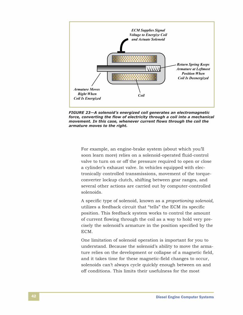
You’ve already studied the fundamental principles of magnet-ism, as well as several vehicle systems that rely on solenoids.A solenoid contains a moveable core, known as an armature,which typically passes through the center of a wire coil.When wire is coiled around an iron (or ferrous metal) core,electrical current flowing through the wire coil creates a mag-netic field, turning the core into what’s known as an electro-magnet (Figure 23). Depending on the direction the currentflows through the coil and the physical location of the com-ponents involved, the core’s magnet force can cause it tomove or to attract or repel other devices. In this way, thesolenoid converts an electrical signal from the ECM to amechanical output.
Diesel Engine Computer Systems42
For example, an engine-brake system (about which you’llsoon learn more) relies on a solenoid-operated fluid-controlvalve to turn on or off the pressure required to open or closea cylinder’s exhaust valve. In vehicles equipped with elec-tronically controlled transmissions, movement of the torque-converter lockup clutch, shifting between gear ranges, andseveral other actions are carried out by computer-controlledsolenoids.
A specific type of solenoid, known as a proportioning solenoid,utilizes a feedback circuit that “tells” the ECM its specificposition. This feedback system works to control the amountof current flowing through the coil as a way to hold very pre-cisely the solenoid’s armature in the position specified by theECM.
One limitation of solenoid operation is important for you tounderstand. Because the solenoid’s ability to move the arma-ture relies on the development or collapse of a magnetic field,and it takes time for these magnetic-field changes to occur,solenoids can’t always cycle quickly enough between on andoff conditions. This limits their usefulness for the most
Armature Moves Right When
Coil Is EnergizedCoil
ECM Supplies SignalVoltage to Energize Coil
and Actuate Solenoid
Return Spring KeepsArmature at Leftmost
Position WhenCoil Is Deenergized
FIGURE 23—A solenoid’s energized coil generates an electromagneticforce, converting the flow of electricity through a coil into a mechanicalmovement. In this case, whenever current flows through the coil thearmature moves to the right.
Diesel Engine Computer Systems 43
demanding fuel-injection applications. Perhaps more impor-tantly from the perspective of a repair technician, solenoid-controlled fuel injectors are partly identified by the time delaythat occurs while building or collapsing its magnetic field.Since the ECM factors this delay into the timing of its fuelscheduling signals, part of the job of changing certain typesof fuel injector nozzles includes entering nozzle-specific data,or calibration codes, which “tell” the ECM about the replace-ment nozzle’s performance characteristics including thoserelated to time response. Piezo-actuated fuel injectors, whichactuate with nearly instantaneous response rates, offer asolution to the time delay that’s experienced with solenoids.
A relay is an electrically controlled switch. Like solenoids,relays rely on a coil-encircled iron core that turns into anelectromagnet whenever electrical current flows through thecoil. In this case, the electric current that generates the elec-tromagnetic force, known as the control or switching current,moves an armature that causes a set of contacts to open orclose (Figure 24). The opening or closing of the contacts con-trols the power circuit, which usually carries much highercurrent than the controlling circuit. In this way, a relativelyweak electrical signal, such as you would expect to comefrom the ECM’s output module, can switch on or off a muchmore powerful electrical current. You’ve almost certainlyencountered many relays in all sorts of vehicle systems, con-trolling power to devices as different as horns and startermotors.

Diesel Engine Computer Systems44
Stepper Motors
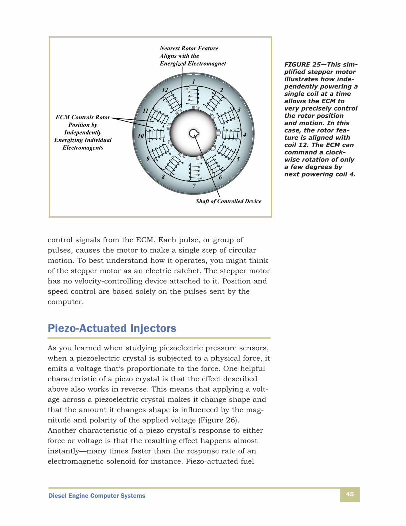
A stepper motor offers precise circular motion. Unlike the con-ventional DC starter motors used in most trucks, a steppermotor has no brushes and doesn’t continuously spin.Instead, it contains several stationary electromagnetsarranged around a rotor that’s part of the motor’s shaftassembly (Figure 25). Applying and turning off current flow toeach of the electromagnets causes the rotor to move preciselyand (usually) by a very small angular amount to align withwhichever electromagnet is currently charged. When accom-plished in a controlled manner, this method of control allowsthe ECM to very exactly define the rotor’s angular position.EGR, inlet air, and other swinging-gate type control valvesare often positioned using a stepper motor.
A stepper motor itself doesn’t normally have a feedback loopto the computer. This motor receives pulse-width-modulated
Switched Power Supply
Coil
Core BecomesMagnetized
When Coil IsEnergized
Armature Is Drawntowards Magnetized Core
Relay Contacts Close toComplete Circuit When
Armature Moves Downward
Signal from ECM Power Output
to Load
FIGURE 24—A relay uses a low-current signal (such as the output from an ECM) to controlthe flow of electricity to a relatively high-power electrical component, like as a motor.
Diesel Engine Computer Systems 45
control signals from the ECM. Each pulse, or group of pulses, causes the motor to make a single step of circularmotion. To best understand how it operates, you might thinkof the stepper motor as an electric ratchet. The stepper motorhas no velocity-controlling device attached to it. Position andspeed control are based solely on the pulses sent by the computer.
Piezo-Actuated Injectors
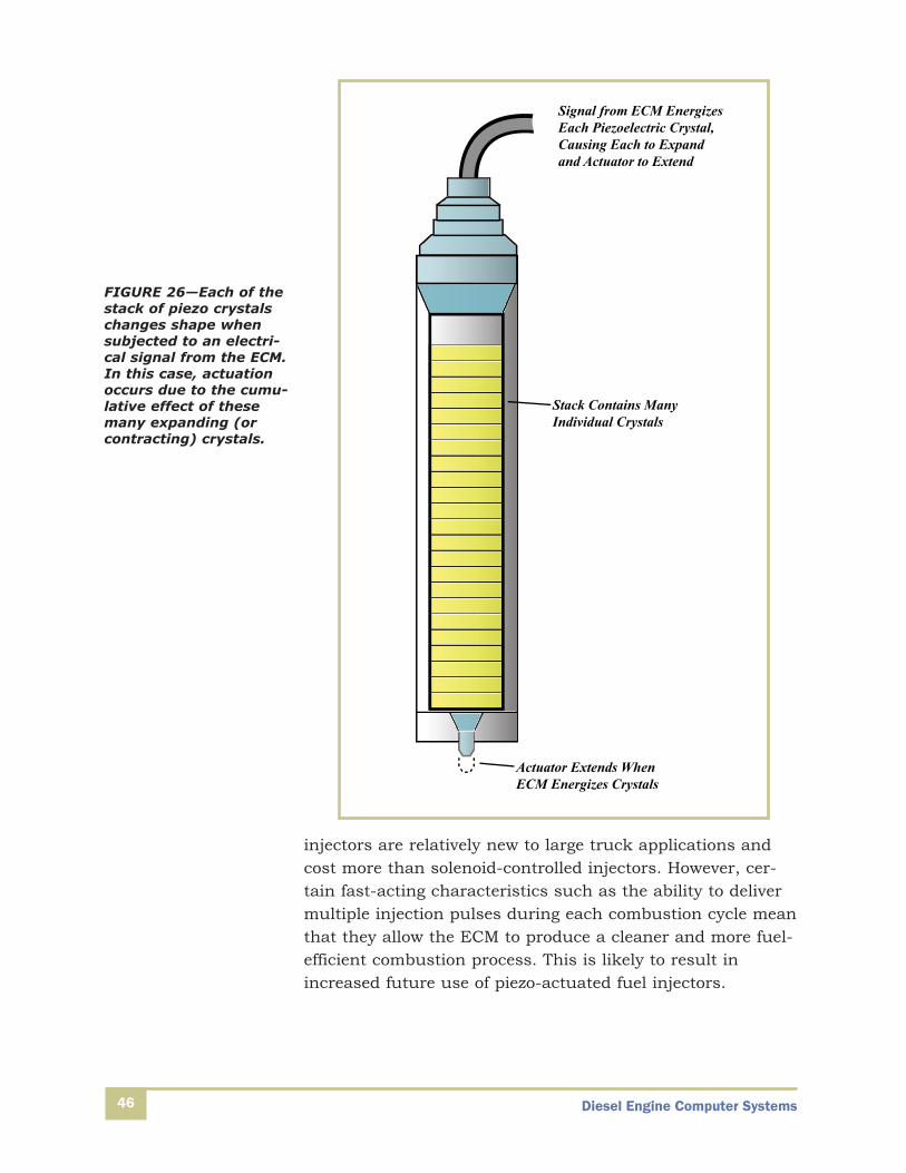
As you learned when studying piezoelectric pressure sensors,when a piezoelectric crystal is subjected to a physical force, itemits a voltage that’s proportionate to the force. One helpfulcharacteristic of a piezo crystal is that the effect describedabove also works in reverse. This means that applying a volt-age across a piezoelectric crystal makes it change shape andthat the amount it changes shape is influenced by the mag-nitude and polarity of the applied voltage (Figure 26).Another characteristic of a piezo crystal’s response to eitherforce or voltage is that the resulting effect happens almostinstantly—many times faster than the response rate of anelectromagnetic solenoid for instance. Piezo-actuated fuel
Shaft of Controlled Device
12
3
4
5
67
8
9
10
11
12
Nearest Rotor FeatureAligns with theEnergized Electromagnet
ECM Controls RotorPosition by
IndependentlyEnergizing Individual
Electromagents
FIGURE 25—This sim-plified stepper motorillustrates how inde-pendently powering asingle coil at a timeallows the ECM tovery precisely controlthe rotor positionand motion. In thiscase, the rotor fea-ture is aligned withcoil 12. The ECM cancommand a clock-wise rotation of onlya few degrees bynext powering coil 4.
Diesel Engine Computer Systems46
Actuator Extends WhenECM Energizes Crystals
Stack Contains Many Individual Crystals
Signal from ECM EnergizesEach Piezoelectric Crystal,Causing Each to Expandand Actuator to Extend
FIGURE 26—Each of thestack of piezo crystalschanges shape whensubjected to an electri-cal signal from the ECM.In this case, actuationoccurs due to the cumu-lative effect of thesemany expanding (orcontracting) crystals.
injectors are relatively new to large truck applications andcost more than solenoid-controlled injectors. However, cer-tain fast-acting characteristics such as the ability to delivermultiple injection pulses during each combustion cycle meanthat they allow the ECM to produce a cleaner and more fuel-efficient combustion process. This is likely to result inincreased future use of piezo-actuated fuel injectors.

Diesel Engine Computer Systems 47
Common Applications of Output Devices
This part of your study unit introduces common applicationsof each output device you’ve studied. Remember that whilenot all OEMs use the same sensors or output devices to con-trol similar systems, their unique system designs mostly relyon similar operating principles.
HPCR Fuel Injection
As you learned earlier in your training program, the majorityof modern ECM-controlled engines incorporate a high-pressure common-rail (HPCR) fuel injection system. These sys-tems employ a low-pressure transfer pump to move fuel fromthe tank, through filters and other conditioners, to a high-pressure pump. The high-pressure pump feeds fuel to aholding container, known as a rail, which connects to allinjectors (Figure 27). The term common rail originates fromthe fact that one rail connects to all injectors, and that therail and all supply lines hold fuel at the same pressure.
The ECM monitors fuel pressure within the rail and outputsa signal to the proportioning-solenoid driven rail pressuremetering valve, which meters the flow of fuel from the high-pressure pump. By adjusting the proportion of fuel flowinginto the rail and drain systems, the ECM precisely maintainsscheduled fuel pressure to each injector.
The fuel injector nozzle includes a series of passages throughwhich pressurized fuel flows and an electrically activated,spring-loaded valve. Valve actuation is achieved by ECM con-trolled solenoids or piezo actuators. The ECM’s programmingrequires that it evaluate many of the input signals youlearned about earlier in this study unit when determining therequired fuel injection timing and duration. Injection timingrefers to when the injection occurs compared to the cylinderpiston’s motion, while the duration of the injection eventdetermines how much fuel is injected.
While it’s common to speak of the injection timing as if itwere a single event, the injection process often includes mul-tiple pulses of fuel or injection events. Multipulse injection,which refers to two or more injection events to the samecylinder during each combustion cycle, assists in reducing

Diesel Engine Computer Systems
emissions, improving operation during cold start, optimizingthe combustion process, or even dosing the diesel particulatefilter, as you’ll soon learn.
Remember, because piezo-actuated valves operate with muchless delay than solenoid-operated ones, nozzles equippedwith piezo actuators are capable of delivering more injectionevents in the same amount of time. This characteristic ofpiezo-actuator equipped engines expands the ECM’s ability tooptimize fuel injection.
48
Engine Control Module
Fuel Rail Pressure Input to ECM
Fuel Rail Pressure Sensor
Fuel Pump DeliversPressurized Fuel to
RailMetering Valve
Drain Line to Fuel Tank
Tank
ECM Output Controls Metering Valve Position
ECM Independently CommandsOpening Point and Duration
for Each Nozzle
High-Pressure FuelLow-Pressure FuelElectrical Signals
Rail
Transfer Pump Delivers Low-Pressure Fuel to Conditioning System and
High-Pressure Fuel Pump
Fuel Nozzles
FIGURE 27—Common-Rail Fuel Injection System

Diesel Engine Computer Systems 49
Variable Turbocharger Geometry
A diesel engine’s air intake system delivers a large volume ofair to the engine cylinders for the combustion process as wellas for cylinder cooling and scavenging of exhaust gases. Thisvolume of incoming air is delivered by the turbocharger,which in many ways greatly improves engine performance. Aturbocharger can be thought of as two connected subsystems.As hot exhaust gas exits the exhaust manifold, it drives aturbine that’s connected to an air-pumping device known asan impeller. A shaft serves as the connection between theexhaust-gas-driven turbine and the impeller, which serves as main working part of the turbocharger’s compressor(Figure 28).
The turbine’s speed depends mostly on the temperature ofexhaust gas and the speed the gas travels after passingthrough a restriction that’s known as a volute. Because theturbine connects directly with the impeller, this means thatthe impeller must also turn faster and therefore pump moreair as engine speeds increase. Under some operating condi-tions, optimal engine operation relies on less (or more) intakeairflow than would normally be delivered with a fixed-geome-try turbine. Fortunately, through the use of computer con-trols and variable-geometry turbocharger technology, turbinespeed can be tailored to meet engine operating conditions.
FilteredIncoming
Air
Impeller Increases Incoming AirPressure and Delivers It to Intake
Manifold
Exhaust Drives Turbocharger’s Turbine
To Exhaust Stack
Turbine Works through Turbocharger’s Common
Shaft to Drive Impeller
High-Pressure AirEnters Engine
through Intake Manifold
Engine
Hot Exhaust Exits Engine through Exhaust Manifold
FIGURE 28—Turbocharger Operating Principle

Diesel Engine Computer Systems50
A variable-geometry turbocharger employs one of two basicmethods to control the delivery of intake air from the tur-bocharger to the intake manifold. Wastegate-controlled tur-bochargers open a gate to allow some of the exhaust gas tobypass the turbine, thus slowing the turbocharger’s shaftspeed, decreasing the flow of intake air, and “wasting” someof the high-energy exhaust gas (Figure 29). Electronicallycontrolled wastegates rely on ECM-activated solenoids toopen or close bypassing gates. Alternatively, the variable tur-bocharger geometry is managed with an ECM-controlledvolute size.
ECM
Exhaust Aftertreatment
Exhaust Manifold
Intake Manifold
Incoming Charge Air
Flow Rate at WhichImpeller Delivers TurbochargedAir to Intake Manifold Depends
on Turbine Speed
Turbine
Impeller
ECM ControlsTurbine / Impeller Speedby Adjusting Waste GatePosition and AllowingSome Exhaust Gas to
Bypass the Turbine
Wastegate
FIGURE 29—Wastegate-Controlled Turbocharger
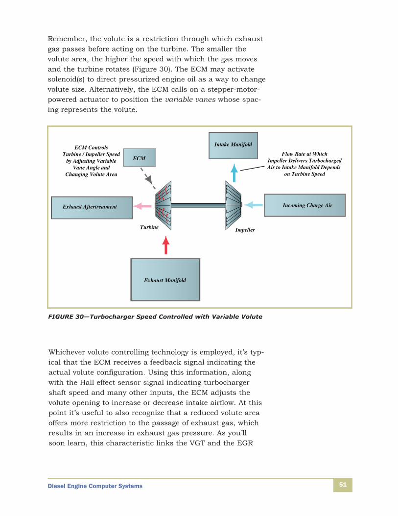
Diesel Engine Computer Systems 51
Remember, the volute is a restriction through which exhaustgas passes before acting on the turbine. The smaller thevolute area, the higher the speed with which the gas movesand the turbine rotates (Figure 30). The ECM may activatesolenoid(s) to direct pressurized engine oil as a way to changevolute size. Alternatively, the ECM calls on a stepper-motor-powered actuator to position the variable vanes whose spac-ing represents the volute.
ECM
Exhaust Aftertreatment
Exhaust Manifold
Intake Manifold
Incoming Charge Air
Flow Rate at WhichImpeller Delivers TurbochargedAir to Intake Manifold Depends
on Turbine Speed
Turbine Impeller
ECM ControlsTurbine / Impeller Speed
by Adjusting VariableVane Angle and
Changing Volute Area
FIGURE 30—Turbocharger Speed Controlled with Variable Volute
Whichever volute controlling technology is employed, it’s typ-ical that the ECM receives a feedback signal indicating theactual volute configuration. Using this information, alongwith the Hall effect sensor signal indicating turbochargershaft speed and many other inputs, the ECM adjusts thevolute opening to increase or decrease intake airflow. At thispoint it’s useful to also recognize that a reduced volute areaoffers more restriction to the passage of exhaust gas, whichresults in an increase in exhaust gas pressure. As you’llsoon learn, this characteristic links the VGT and the EGR

Diesel Engine Computer Systems52
system configurations in determining the ratio of recirculatedexhaust gas and intake air directed into the engine’s cylinders.
Emission-Control Systems
The emission-control system of a modern vehicle uses inputsensors, output devices, and computers to limit the emissionof various pollutants. Engine manufacturers incorporateEGR, SCR, DPF, and other emission-controlling devices toreduce the amount of pollutants produced by the engine anddelivered to the environment. To a large degree, these designchanges have been successful, although the introduction ofSCR technology means that engines built after 2010 dependless on EGR systems to reduce NOx emissions. Their heavyreliance on engine-management computers means that mod-ern emission-control systems operate more effectively thanever.
The exhaust-gas-recirculation, or EGR, system routes someexhaust gas through a cooler after which it mixes with pres-surized intake air as it exists the turbocharger’s compressor.This process reduces the quantity of oxygen in the combus-tion process by substituting some amount of “dead” or oxy-gen-free gas in place of oxygen-charged intake air. Less oxy-gen available for combustion results in a reduction of NOxlevels in the engine’s exhaust.
The ECM typically controls the flow of recirculated exhaustgas in two ways (Figure 31). An ECM-controlled steppermotor positions the (usually) butterfly-style EGR valve. Theamount this valve is open, as well as the exhaust gas pres-sure level, which varies with VGT configuration, determineshow much gas flows from the exhaust system to the EGRsystem. EGR valve position is typically a closed-loop controlsystem, with input data from the EGR-valve position sensor,intake manifold MAF sensor, exhaust manifold pressure sen-sor, the EGR flow sensor, and various temperature sensorsserving as inputs to the ECM and the EGR valve position asan ECM output.
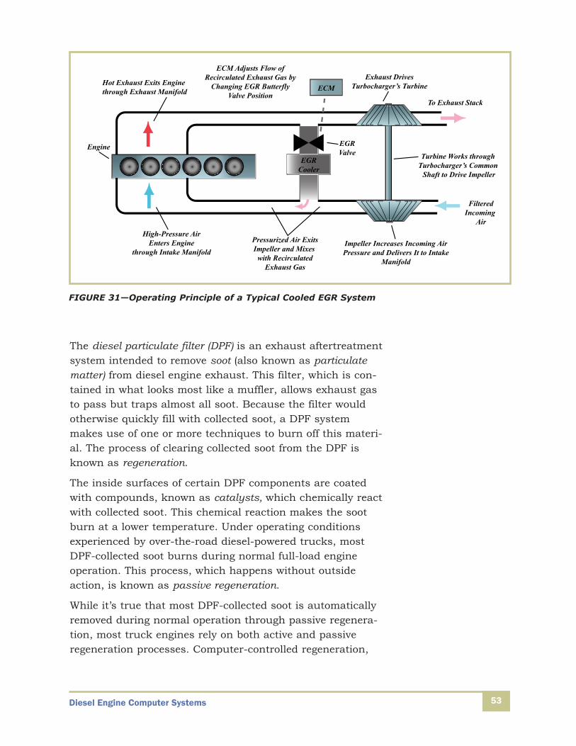
Diesel Engine Computer Systems 53
The diesel particulate filter (DPF) is an exhaust aftertreatmentsystem intended to remove soot (also known as particulatematter) from diesel engine exhaust. This filter, which is con-tained in what looks most like a muffler, allows exhaust gasto pass but traps almost all soot. Because the filter wouldotherwise quickly fill with collected soot, a DPF systemmakes use of one or more techniques to burn off this materi-al. The process of clearing collected soot from the DPF isknown as regeneration.
The inside surfaces of certain DPF components are coatedwith compounds, known as catalysts, which chemically reactwith collected soot. This chemical reaction makes the sootburn at a lower temperature. Under operating conditionsexperienced by over-the-road diesel-powered trucks, mostDPF-collected soot burns during normal full-load engineoperation. This process, which happens without outsideaction, is known as passive regeneration.
While it’s true that most DPF-collected soot is automaticallyremoved during normal operation through passive regenera-tion, most truck engines rely on both active and passiveregeneration processes. Computer-controlled regeneration,
FilteredIncoming
Air
Impeller Increases Incoming AirPressure and Delivers It to Intake
Manifold
Exhaust Drives Turbocharger’s Turbine
To Exhaust Stack
Turbine Works through Turbocharger’s Common
Shaft to Drive Impeller
High-Pressure AirEnters Engine
through Intake Manifold
Engine
Hot Exhaust Exits Engine through Exhaust Manifold
EGRCooler
EGRValve
ECM
Pressurized Air ExitsImpeller and Mixes
with RecirculatedExhaust Gas
ECM Adjusts Flow ofRecirculated Exhaust Gas by
Changing EGR ButterflyValve Position
FIGURE 31—Operating Principle of a Typical Cooled EGR System
Diesel Engine Computer Systems54
commonly referred to as active regeneration, in some casesoccurs when a computer-controlled auxiliary fuel injectorsprays fuel into a component upstream of the DPF, known asa diesel oxidation catalyst (DOC). Gas temperature exiting theDOC is sufficiently high to burn the soot contained in thedownstream DPF.
Depending on the system’s design, active regeneration ofteninvolves the addition of fuel to the soot that’s collected in theDPF filter. This fuel may come from a computer-controlled,solenoid-operated dosing fuel injector that’s actually part ofthe DPF system and sprays fuel directly on the filter, or bythe ECM-commanded addition of extra fuel, through enginefuel-injection nozzles, after the combustion process is com-plete and as the exhaust gases are driven from the cylinder.In this case, the exhaust gas carries this extra fuel onto theparticulate filter where it soaks the trapped soot.
Whichever method is employed to add fuel to the filter, the DPFmust be hot enough for the collected soot to burn. Duringactive regeneration, the ECM monitors various DPF systemtemperatures to be sure there’s sufficient heat to burn thetrapped soot. Where insufficient heat is present, the ECM may produce elevated exhaust temperature by temporarilyadjusting the engine’s air-fuel ratio. In other system designs, acomputer-controlled spark plug ignites injected dosing fuel asit sprays on the collected soot.
To support the DPF regeneration process, the ECM (or DPF-dedicated computer module) receives information from vari-ous temperature sensors, described earlier in this study unit.The computer is also able to monitor the amount of soot loadin the DPF with the use of a delta-pressure sensor. Datafrom these input sensors, together with collected engineoperating data, allows the computer system to “know” whenand if active regeneration is required.
Selective catalytic reduction (SCR) technology is a more up-to-date system that controls NOx emissions more effectivelythan EGR, and without the negative impact on engine per-formance that results from the recirculation of exhaust gasinto the combustion process. Like the diesel particulate filter,the SCR system is an exhaust aftertreatment process (Figure 32). In this case, urea-based diesel exhaust fluid
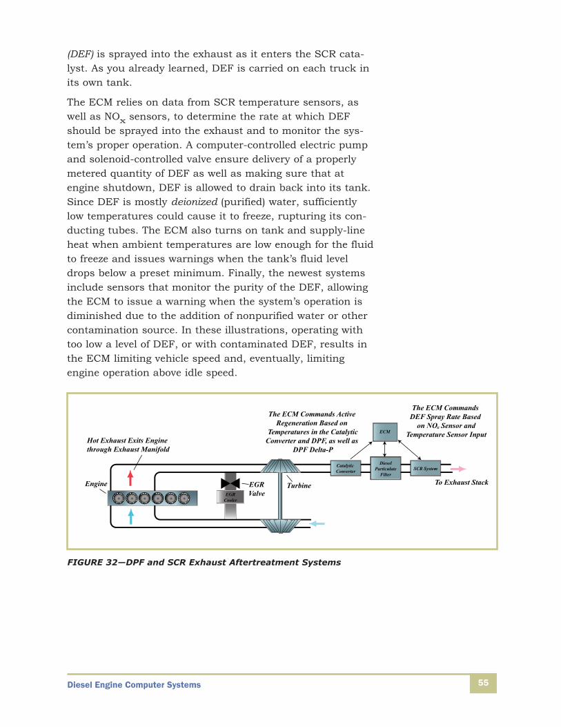
Diesel Engine Computer Systems 55
(DEF) is sprayed into the exhaust as it enters the SCR cata-lyst. As you already learned, DEF is carried on each truck inits own tank.
The ECM relies on data from SCR temperature sensors, aswell as NOx sensors, to determine the rate at which DEFshould be sprayed into the exhaust and to monitor the sys-tem’s proper operation. A computer-controlled electric pumpand solenoid-controlled valve ensure delivery of a properlymetered quantity of DEF as well as making sure that atengine shutdown, DEF is allowed to drain back into its tank.Since DEF is mostly deionized (purified) water, sufficientlylow temperatures could cause it to freeze, rupturing its con-ducting tubes. The ECM also turns on tank and supply-lineheat when ambient temperatures are low enough for the fluidto freeze and issues warnings when the tank’s fluid leveldrops below a preset minimum. Finally, the newest systemsinclude sensors that monitor the purity of the DEF, allowingthe ECM to issue a warning when the system’s operation isdiminished due to the addition of nonpurified water or othercontamination source. In these illustrations, operating withtoo low a level of DEF, or with contaminated DEF, results inthe ECM limiting vehicle speed and, eventually, limitingengine operation above idle speed.
Turbine To Exhaust StackEngine
Hot Exhaust Exits Engine through Exhaust Manifold
EGRCooler
EGRValve
Catalytic Converter
DieselParticulate
FilterSCR System
ECM
The ECM Commands Active Regeneration Based on
Temperatures in the CatalyticConverter and DPF, as well as
DPF Delta-P
The ECM Commands DEF Spray Rate Based
on NO Sensor andTemperature Sensor Input
x
FIGURE 32—DPF and SCR Exhaust Aftertreatment Systems
Diesel Engine Computer Systems56
Engine Cooling Fan System
Earlier in this study unit, you learned that the developmentand evolution of computer-controlled systems has producedengines that last longer, consume less fuel, and emit lesspollution. A less obvious way that a computer-controlled sys-tem helps modern engines achieve these goals is by control-ling the cooling fan. The engine’s cooling system relies on thefan to help remove heat from the radiator and other heat-exchangers whenever the natural flow of air through theengine compartment, known as ram air, is insufficient. Whenan over-the-road truck engine’s cooling fan is driven by thecrankshaft, it consumes energy that could otherwise bespent powering the vehicle and its load of freight. For thisand other reasons, it’s preferable to operate the fan only asmuch as needed.
When an ECM system controls the engine cooling fan, itworks to minimize the energy the engine puts into driving thefan while ensuring that the coolant and engine-compartmenttemperatures remain in an acceptable range. To decide whento turn on the fan, the ECM relies on data from various tem-perature sensors as well as other data indicating when moreor less cooling will soon be required. For example, the enginefan may be engaged when the ECM senses the switching onof cabin air conditioning, which will in various ways eventu-ally add heat to the engine compartment.
An engine operates most efficiently under constant condi-tions. Turning a high-output fan either fully on or off when-ever a sensed temperature reaches a programmed limit does-n’t result in very steady operating conditions. When the fanis turned fully on or off, several less-than-ideal things hap-pen, including the following:
• An abrupt physical load is applied to the belts and otherhardware responsible for carrying energy from thecrankshaft to the fan.
• There are relatively large swings in engine coolant andcompartment temperature, which increases the load onmechanical components as well as heat-sensitive elec-tronic ones.
Diesel Engine Computer Systems 57
• The changing engine temperature, and therefore operat-ing conditions, makes it more difficult for the ECM toprecisely control engine operation and limit fuel consumption.
ECM control of cooling fan hubs now allows for variable-speed cooling fans, which can be precisely scheduled to deliver just the amount of airflow required by current orsoon-to-take-effect heating loads. Also important is the abili-ty for the ECM to gradually change the speed of these fans toprevent the large and rapid changes in engine and enginecompartment temperature experienced with a full on / fulloff fan control system. In a variable-speed fan control sys-tem, an ECM controlled proportioning solenoid positions afluid-controlled valve, which regulates fan speed by directingthe flow of hydraulic fluid in the fan hub’s drive system.
Engine Brake Solenoids
As you may remember from earlier studies, an engine brakesystem works to slow a vehicle without relying on the pri-mary braking system that acts on the tractor and trailerwheels. By actuating a collection of solenoid-controlledvalves, an engine brake system converts the engine from apower-producing device into a power-absorbing one. This isaccomplished by using one or more of the engine’s cylindersto compress air, exhaust gas, or both, without the addition ofdiesel fuel. In this way, the vehicle’s drive wheels supplypower through the drivetrain and crankshaft, driving the pis-ton(s) to act as a compressor. The act of supplying power tothe drivetrain causes the drive wheels to turn more slowly,thus reducing the speed of the vehicle.
Two specific categories of engine brakes, known as compres-sion braking systems, convert some of the vehicle’s energy ofmotion into pressurized (and thus heated) gas. In an internalcompression brake, one or more cylinders complete the com-pression stroke without the addition of fuel. Instead, whenthe piston reaches the top of its compression stroke, a sole-noid commands the exhaust valve to open, releasing thecompressed air. If you consider that the piston requires
Diesel Engine Computer Systems58
power to compress the air in the cylinder, and that thispower is supplied to the piston by the drive wheels, then it’seasier to understand how this process would add resistanceto the drive wheels’ ability to turn and, therefore, slow thevehicle.
An external compression engine brake also draws power fromthe drive wheels to act on one or more cylinders, turning itinto a compressor. However, in this case an activated sole-noid blocks the passage of exhaust gas, converting the cylin-der’s exhaust stroke into a compression stroke and increas-ing the pressure of the trapped exhaust gas. Again, when theexternal engine brake is activated, the braking cylinder(s)isn’t supplied with fuel.
In modern engine brake systems, the ECM withholds fuelfrom the cylinder(s) engaged in braking, actuates the valve-controlling solenoids, and adjusts the level of compressionbraking by increasing or decreasing the number of cylindersemployed as engine brakes. In some designs, the enginebrake system operates simultaneously as both an internaland external compression brake. While the level of compres-sion braking applied is often based on driver input, the ECMcan also automatically deploy the engine brake, and adjustits level of braking, to maintain a cruise-control speed set bythe driver or to slow the vehicle during an accident-avoidanceevent.
Indicator Lights and Fault Codes
Much of your training is ultimately intended to help youmore effectively maintain and troubleshoot engine and vehi-cle systems. As you’ve learned, computer-controlled systemsdepend on input devices, most notably sensors, to monitoroperating characteristics like pressure and temperature andreport their measurements back to the computer. The com-puter uses this input data, along with the instructions withwhich it has been programmed, to decide what actions totake. These actions are accomplished through the computer’scommand of output devices.
An ECM or other computer is programmed to “know” approx-imately what measurement signal it should receive from the
Diesel Engine Computer Systems 59
sensor and what reaction it should observe after sending aspecific command to an output device. When the computerobserves an incoming measurement or response to an out-going command that differs from the values it’s programmedto expect, it sends a message to alert the driver and/or maintenance technician of a possible problem. While the typeof message the computer sends depends on the type and severity of the problem, this message is typically viewed bythe technician as a fault or trouble code.
Engine Fault Indicator Lamps
Even though the types of fault-code indicators visible to anoperator vary depending on the age and OEM of a vehicle,fault indicator lights can be grouped into a few general cate-gories. The ECM outputs a signal to illuminate the checkengine lamp, which is yellow, when an engine fault is detected. This light warns the driver of a fault but doesn’trequire that the vehicle be shut down. In some cases, thetype of sensed fault may lead the ECM to operate the enginein a derated mode. If the sensed fault poses an immediatedanger of engine damage, the ECM illuminates the red stopengine lamp. This warns the driver to stop the vehicle assoon as is safely possible.
When either of these engine indictor lamps is illuminated,you can quickly determine the fault code set by the ECM.The required procedure varies depending on vehicle OEM,but usually you’ll turn the ignition key on and off in arequired pattern or activate a dashboard-mounted diagnosticswitch to access the code. When either the check or stopengine lamps are illuminated, following the applicable proce-dure causes the indicator lamp, or an ECM-mounted diag-nostic lamp, to flash a specific number of times. The numberof flashes defines a flash code, which identifies the problemresponsible for the lamp illuminating. OEM-provided lookuptables allow you to quickly identify the fault code based onthe number of flashes. Of course you can also gain the sameinformation (and more) with the use of a handheld electronicservice tool or computer, as we’ll discuss shortly.
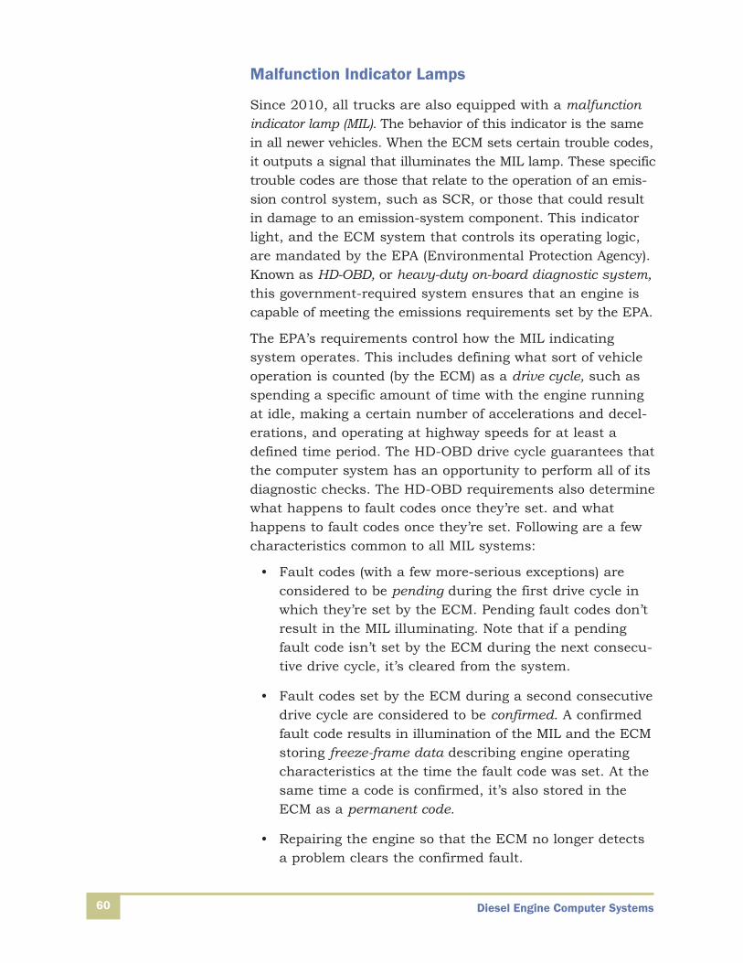
Diesel Engine Computer Systems60
Malfunction Indicator Lamps
Since 2010, all trucks are also equipped with a malfunctionindicator lamp (MIL). The behavior of this indicator is the samein all newer vehicles. When the ECM sets certain trouble codes,it outputs a signal that illuminates the MIL lamp. These specifictrouble codes are those that relate to the operation of an emis-sion control system, such as SCR, or those that could resultin damage to an emission-system component. This indicatorlight, and the ECM system that controls its operating logic,are mandated by the EPA (Environmental Protection Agency).Known as HD-OBD, or heavy-duty on-board diagnostic system,this government-required system ensures that an engine iscapable of meeting the emissions requirements set by the EPA.
The EPA’s requirements control how the MIL indicating system operates. This includes defining what sort of vehicleoperation is counted (by the ECM) as a drive cycle, such asspending a specific amount of time with the engine runningat idle, making a certain number of accelerations and decel-erations, and operating at highway speeds for at least adefined time period. The HD-OBD drive cycle guarantees thatthe computer system has an opportunity to perform all of itsdiagnostic checks. The HD-OBD requirements also determinewhat happens to fault codes once they’re set. and what happens to fault codes once they’re set. Following are a fewcharacteristics common to all MIL systems:
• Fault codes (with a few more-serious exceptions) areconsidered to be pending during the first drive cycle inwhich they’re set by the ECM. Pending fault codes don’tresult in the MIL illuminating. Note that if a pendingfault code isn’t set by the ECM during the next consecu-tive drive cycle, it’s cleared from the system.
• Fault codes set by the ECM during a second consecutivedrive cycle are considered to be confirmed. A confirmedfault code results in illumination of the MIL and the ECMstoring freeze-frame data describing engine operatingcharacteristics at the time the fault code was set. At thesame time a code is confirmed, it’s also stored in theECM as a permanent code.
• Repairing the engine so that the ECM no longer detectsa problem clears the confirmed fault.
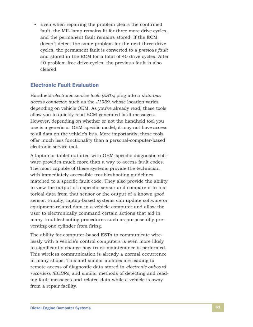
Diesel Engine Computer Systems 61
• Even when repairing the problem clears the confirmedfault, the MIL lamp remains lit for three more drive cycles,and the permanent fault remains stored. If the ECMdoesn’t detect the same problem for the next three drivecycles, the permanent fault is converted to a previous faultand stored in the ECM for a total of 40 drive cycles. After40 problem-free drive cycles, the previous fault is alsocleared.
Electronic Fault Evaluation
Handheld electronic service tools (ESTs) plug into a data-busaccess connector, such as the J1939, whose location variesdepending on vehicle OEM. As you’ve already read, these toolsallow you to quickly read ECM-generated fault messages.However, depending on whether or not the handheld tool youuse is a generic or OEM-specific model, it may not have accessto all data on the vehicle’s bus. More importantly, these toolsoffer much less functionality than a personal-computer-basedelectronic service tool.
A laptop or tablet outfitted with OEM-specific diagnostic soft-ware provides much more than a way to access fault codes.The most capable of these systems provide the technicianwith immediately accessible troubleshooting guidelinesmatched to a specific fault code. They also provide the abilityto view the output of a specific sensor and compare it to his-torical data from that sensor or the output of a known goodsensor. Finally, laptop-based systems can update software orequipment-related data in a vehicle computer and allow theuser to electronically command certain actions that aid inmany troubleshooting procedures such as purposefully pre-venting one cylinder from firing.
The ability for computer-based ESTs to communicate wire-lessly with a vehicle’s control computers is even more likelyto significantly change how truck maintenance is performed.This wireless communication is already a normal occurrencein many shops. This and similar abilities are leading toremote access of diagnostic data stored in electronic onboardrecorders (EOBRs) and similar methods of detecting and read-ing fault messages and related data while a vehicle is awayfrom a repair facility.

Diesel Engine Computer Systems62
Self-Check 3Complete the following statements with the correct answer.
1. The movable core of a solenoid is referred to as its _______.
2. True or False? As it takes time for magnetic field changes to build in a solenoid, solenoids are less well suited than piezo actuators for the most demanding fuel-injection applications.
3. True or False? A stepper motor always has an attached velocity-controlling device.
4. ______ -actuated fuel injectors provide much faster response rates than those achieved bysolenoid-controlled injectors.
5. True or False? The term injection timing refers to the point at which fuel injection begins.
6. A(n) ______ delivers a large volume of air to the engine cylinders for combustion and cylindercooling.
7. True or False? Since 2010, engines have relied heavily on selective catalytic reduction tech-nology to control quantities of certain types of emissions.
8. ______ is the name of the process for clearing collected soot from the diesel particulate filterin an exhaust aftertreatment system.
9. True or False? Operating with an empty diesel exhaust fluid tank will, in the newest engines,result in the ECM limiting vehicle speed.
10. An engine braking system that converts some of the vehicle’s energy of motion into pressur-ized gas is known as a(n) ______ braking system.
Check your answers with those on page 64.

63
Self-Check 11. F
2. voltage
3. T
4. engine brake
5. T
6. analog
7. F
8. digital
9. closed-loop
Self-Check 21. F
2. resistance temperature detector (RTD)
3. T
4. dielectric
5. F
6. differential-pressure or delta-P
7. T
8. rheostat
9. F
10. exhaust-gas-recirculation (EGR)
Answers
Answers
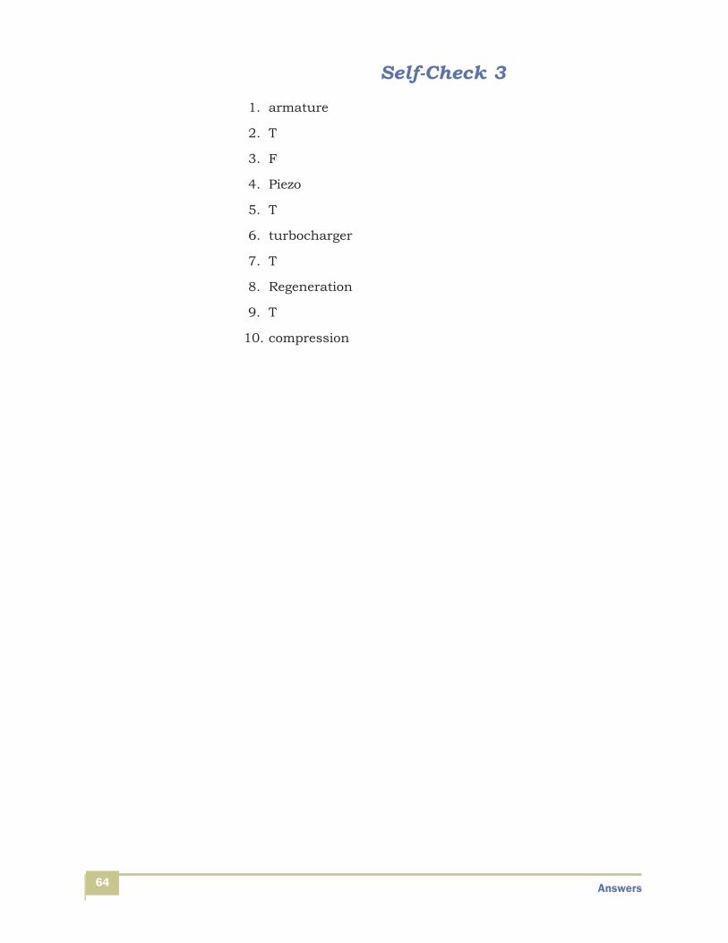
Self-Check 31. armature
2. T
3. F
4. Piezo
5. T
6. turbocharger
7. T
8. Regeneration
9. T
10. compression
Answers64
Related Documents