Study on the Impact of Turbine Controls on Transient Stability of Synchronous Machine Akhil S. Menon 1 , N. Ramesh Babu 1,∗ and Sreedhar Desabhatla 2 1 School of Electrical Engineering, VIT University, Vellore, India-632014 2 GE Power, General Electric, Garching b. Munchen-85748, Germany E-mail: [email protected]; [email protected]; [email protected] *Corresponding Author Received 29 August 2016; Accepted 11 November 2016; Publication 22 November 2016 Abstract This article discusses the work carried out in the development, validation and verification of the Turbine/Governor model (GGOV1) in GE Control Systems Toolbox to comprehend the impact of Turbine controls post system transient. Simulation related studies are carried out using the model deve- loped. MATLAB /Simulink has been used as the platform for validating the model. The validated model is replicated in the GE Control System Toolbox , for enhanced grid Simulation related studies. Comparative analysis of results obtained in both platforms with the validated parameters has been accomplished. Keywords: GGOV1 Turbine/Governor model, Frequency transient, MATLAB /Simulink , GE Control Systems Toolbox , Gas Turbine. 1 Introduction In studies related to Power System, the Turbine/Governor models mainly deal with overall stability of the system. Stability related experiments concentrate Journal of Green Engineering, Vol. 6 2, 1–22. doi: 10.13052/jge1904-4720.624 c 2016 River Publishers. All rights reserved.

Welcome message from author
This document is posted to help you gain knowledge. Please leave a comment to let me know what you think about it! Share it to your friends and learn new things together.
Transcript

Study on the Impact of Turbine Controlson Transient Stability
of Synchronous Machine
Akhil S. Menon1, N. Ramesh Babu1,∗ and Sreedhar Desabhatla2
1School of Electrical Engineering, VIT University, Vellore, India-6320142GE Power, General Electric, Garching b. Munchen-85748, GermanyE-mail: [email protected]; [email protected];[email protected]*Corresponding Author
Received 29 August 2016; Accepted 11 November 2016;Publication 22 November 2016
Abstract
This article discusses the work carried out in the development, validationand verification of the Turbine/Governor model (GGOV1) in GE ControlSystems Toolbox� to comprehend the impact of Turbine controls post systemtransient. Simulation related studies are carried out using the model deve-loped. MATLAB�/Simulink� has been used as the platform for validatingthe model. The validated model is replicated in the GE Control SystemToolbox�, for enhanced grid Simulation related studies. Comparative analysisof results obtained in both platforms with the validated parameters has beenaccomplished.
Keywords: GGOV1 Turbine/Governor model, Frequency transient,MATLAB�/Simulink�, GE Control Systems Toolbox�, Gas Turbine.
1 Introduction
In studies related to Power System, the Turbine/Governor models mainly dealwith overall stability of the system. Stability related experiments concentrate
Journal of Green Engineering, Vol. 6 2, 1–22.doi: 10.13052/jge1904-4720.624c© 2016 River Publishers. All rights reserved.

2 A. S. Menon et al.
on areas like the transient rotor angle stability, voltage stability, frequencystability & small signal stability. Definitions of each of the above mentionedstability related issues are given in [1]. In reality, these stability issues areinterrelated. In most of the smaller systems, a single grid related event cancreate multiple allied issues of voltage, angular, and frequency stability.
Therefore, Turbine/Governor modelling is one of the key criteria requiredfor investigations on previously mentioned stability issues, and to a limitedextent for small signal stability. Regarding this last mentioned area, negativedamping effect for the rotor oscillations will be there for the Turbine/Governormodels in the required range of frequency. In synchronous generators, usingPSS [2, 3] damping can me improved for different modes of rotor oscillations.Proper tuning of PSS avoids such negative damping issues. High gain basedautomatic voltage regulators are one of influential source of negative dampingproblem [2].
The turbine-governor is very important for carrying out transient rotorangle stability related studies. In the initial second or two after a disturbanceat the grid, the dynamics of Turbine/Governor model is of great importance.For the modelling required for transient stability related studies, the controlsaffecting the mechanical output during a grid fault are critical. One of thelatest technologies used for regulating the frequency transients in grid, therebymaintain the output power, is through the implementation of pitch anglecontroller [9, 12] or a pitch blade controller [10] which is designed using aconventional PI controller. Acceleration controls [27] provided for gas turbineis another example for the above mentioned case. Acceleration control ismandatory for gas turbines. Provisions like implementation of droop control[11] through electrical power feedback, use of PI or PID controller in thecontrols of turbine governor (very common on modern gas turbine models)have effect on the transient stability. Active & reactive power regulation forturbines is nowadays provided through variable universe fuzzy controller(VUFC) [13], PI controllers & Direct Power Control [DPC] [18]. Therefore,modelling has to be carried out accordingly. In micro grid applications also,PI controllers are widely used for the regulation of frequency transients [16].
Turbine/Governor models also play a very important role in frequencystability. In power system performance, frequency response plays a criticalrole. Depending on the amount of Megawatt loss, Load characteristics,System Inertia, load loss, System droop, and the online responsive gener-ation, system’s actual frequency response will be varying from each andevery event. Load frequency control for Gas Turbines can be done using PIcontrollers which is developed and tuned through Genetic Algorithm method(GA), Ziegler Nichols’ method (ZN), and Fuzzy Gain Scheduling method

Study on the Impact of Turbine Controls on Transient Stability 3
(FGS) [14]. Fractional order proportional integral controller (FOPI) [15]which can be operated in full load region along with ensuring reliability &performance required for integrating into the electric grid, gives more accurateperformance compared to PI controllers, by introducing a tuning parameterknown as the integral fractional-order.
As mentioned above, another important aspect of Turbine/Governordynamics is the initial response of the Turbine Governor in the initial secondor two, following any of the above mentioned grid disturbances.
With all the above mentioned cases, it can be understood that providingthe exact specification required for the model performance for all studycases are difficult. Generally, we can say that, for typical planning relatedstudies, the main intention is to simulate events where system can stay intactpredominantly. For large systems like that in North America, the deviation infrequency in typical cases is maximum ±1% with 0.3 Hz/s as the maximuminitial rate change. For smaller island systems, the deviation in frequency willbe maximum of ±5% with 1 to 2 Hz/s as the maximum initial rate change.
Therefore, with behalf of the time scale of interest, the type of the modeland its validation requirement can be decided.
2 Methodology
The GGOV1 model [4] structure shown in Figure 1, was developed in acollaborative effort involving GE Power and Water (then GE Energy) andEnergy Consulting staff in the late 1990’s. This model released by GE isan open source model used for dynamic simulation based research studies,that has been widely accepted by various international electrical systemscouncils like IEEE [4], CIGRE [4] and WECC [8].Also, GGOV1 is one amongthe leading Turbine/Governor model that is still available in the commonlyused simulation based programs/tools. Hence, various new models developedor being developed for modelling hydro turbines, modern combine cyclepower plants & thermal turbine governors are consolidated by comparingwith the performance of this model. Hence, this model has been used forthe dynamic simulation based studies shown in this paper. This paper doesnot claim to comment or address any grid codes or standards. Developingthis Turbine/Governor Control Model in GE Control Systems Toolbox�,would help to integrate to Electrical Models, for more accurate Simulationstudies. MATLAB�/Simulink� is been used as the design platform for thestudies required. These models have been replicated in the GE Control SystemToolbox�, for enhanced simulation studies such as analysing the impact of

4 A. S. Menon et al.
Figure 1 GGOV1 model structure [4].
mechanical power modulation during an excursion in power system. Theproposed statements of the work are to validate the Governor models inSimulink�, where the models are provided and to develop the equivalentcode in GE Controls Platform, and to validate the accuracy of response of GEToolbox with that of MATLAB�/Simulink�.
2.1 Model Description
The GGOV1 Turbine/governor model developed is a general – PurposeTurbine/Governor model which is used for carrying out dynamic Simulationrelated studies. This model is not at all a detailed thermodynamic treatment.It is a representation having simplified linear transfer function.
In terms of gas turbine, simplifying assumptions [5, 6] are made for themodel as follows:
• IGVs (Inlet Guide Vanes) are neglected.• A temperature limit or load limit as a constant has been assumed.• No explicit representation of ambient or other effects.

Study on the Impact of Turbine Controls on Transient Stability 5
As IGV’s are neglected, it will result in an assumption, that is, the onlyparameter defining the generation of power will be fuel flow. So, mechanicalpower at steady state (Pmech) developed from GGOV1 Turbine/Governormodel is given by the following equation:
Pmech = Kturb ∗ (Wf − Wfnl) (1)
Where,
Wf = Fuel flow at full speed, loaded conditionsWfnl= Fuel flow at full speed, no load conditionsKturb = Turbine gain
The main feature of this model is its flexibility for providing different controloptions and signals for feedback, namely:
• PID control provided for speed error signal produced by speed reference,speed, and droop signal.
• PI control provided for the speed error signal produced by speedreference, speed and droop signal.
• P control provided for the speed error signal produced by speed referenceand speed.
Droop signal [7] is obtained many feedback signals namely, electric power,valve stroke or governor output. In the last case of control design whereproportional control is provided, the reciprocal for proportional gain willdefine droop. No other signal is required for defining droop. The guidelinesrequired for Modelling of GT is provided in [8, 21–24]. Also, experimentalempirical transfer function models for gas turbines (GT) can be done [17].
3 Implementation
3.1 Development
The GE GGOV1 Turbine/Governor model discussed above was primarily builtin MATLAB�/Simulink�. MATLAB�/Simulink� was used as the platformfor validating this model, so that the validated model was targeted to be builtin GE Control Systems Toolbox box�, in order to carry out the necessarysimulations required for dynamic power system studies. Figure 2, representsthe MATLAB�/Simulink� representation of GGOV1 model.
The Turbine/Governor model has to be linked to ad-q model of syn-chronous machine, which is used for determining the mechanical power of the

6 A. S. Menon et al.
Figure 2 GGOV1 model representation in MATLAB�/Simulink�.
shaft (Pmech) and the mechanical torque (Tmech) required for the generatormodels shown in [25].
The solver used was ode45 (Dormand-Prince) [26] for the simulationwith a variable step with maximum step size of 5 ms. GGOV1 MATLAB�/Simulink� model is built with load controller (which is an integrator) incor-porated, along with governor, acceleration and temperature control. In themodel, as shown in Figure 2, the model was initialized with a setpoint MWvalue of 0.6 Pu.
Since we are defining our model with a rated droop 4%, which means forone % change in our system frequency will make the governor to provide25% change in MW power output, we need to make the load controller logicwhich works accordingly with the speed droop characteristic incorporated, sothat the load controller will provide a regulated output in accordance with thechanges in frequency. Load controller used here is similar to lcfb1 controller[8]. Here, the power controller reset gain (Kimw) is taken as 0.02. The rate, atwhich mechanical power output (Pmech) follows the setpoint value (Pmwset),depends on Kimw (i.e. If Kimw is less, Pmech follows Pmwset fast & viceversa is also true).

Study on the Impact of Turbine Controls on Transient Stability 7
From Figure 3, in case a transient occurs, change in speed is multiplied witha gain and load controller provides a load reference (Pref1) to the governorwhich is equal to the reciprocal of droop (i.e. for 4% droop setting, gainwill be 25 which is same to the change in power output % for the droopsetting provided). The speed droop characteristic will come into action. Ifload controller is not being used, Kimw will be zero, thereby; load reference(Pref1) will be equal to zero and speed reference (Pref0) will be active. IfPref0 is active, speed reference (Pref) will be taken as Pref0 only, which willvary according to the speed droop logic and not a fixed value.
After the load controller section, comes the speed governor section of themodel shown in Figure 3, where the speed controller or fsrn regulator wasprovided with PI controller logic. Here, as we made the load controller inaction, the speed reference (Pref) is taken as a constant, which is equal to sumof our rated speed and rated droop (i.e. 1.04 Pu), when load controller is active.Otherwise Pref will be equal to Pref0 as mentioned above. The main key pointof this section is that, a feedback from the electrical power (Pe) incorporated
Figure 3 Load control section of GGOV1 MATLAB�/Simulink� model.

8 A. S. Menon et al.
with the rated droop as gain has been provided to the speed governor, alongwith the speed feedback.
The logic is that, when a frequency transient occur, the electrical powerwill be changing (i.e. When speed decreases, electrical power increases & viceversa), and load controller will be providing a regulated output (load ref) tothe speed governor. At the speed governor section, the negative feedbackof electrical power (Pe) equal will be also changing. Since speed droopcharacteristic is a logic defined for neutralizing the deviation in frequencyoccurred in the grid, by changing the load correspondingly, thereby bringingthe system back to steady state condition, we can see that in the above model,load controller output (load ref) and electrical power feedback to the speedgovernor, both incorporated with droop logic, will work to neutralize thefrequency transient occurred, thereby bringing the system back to steady state.
The speed governor being used is made according to the PI regulator logicimplemented as shown in Figure 5, where the proportional controller with gain
Figure 4 Speed governor section of GGOV1 MATLAB�/Simulink� model.
Figure 5 Speed controller section of GGOV1 MATLAB�/Simulink� model.
Study on the Impact of Turbine Controls on Transient Stability 9
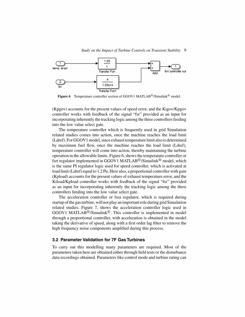
Figure 6 Temperature controller section of GGOV1 MATLAB�/Simulink� model.
(Kpgov) accounts for the present values of speed error, and the Kigov/Kpgovcontroller works with feedback of the signal “fsr” provided as an input forincorporating inherently the tracking logic among the three controllers feedinginto the low value select gate.
The temperature controller which is frequently used in grid Simulationrelated studies comes into action, once the machine reaches the load limit(Ldref). For GGOV1 model, since exhaust temperature limit also is determinedby maximum fuel flow, once the machine reaches the load limit (Ldref),temperature controller will come into action, thereby maintaining the turbineoperation in the allowable limits. Figure 6, shows the temperature controller orfsrt regulator implemented in GGOV1 MATLAB�/Simulink� model, whichis the same PI regulator logic used for speed controller, which is activated atload limit (Ldref) equal to 1.2 Pu. Here also, a proportional controller with gain(Kpload) accounts for the present values of exhaust temperature error, and theKiload/Kpload controller works with feedback of the signal “fsr” providedas an input for incorporating inherently the tracking logic among the threecontrollers feeding into the low value select gate.
The acceleration controller or fsra regulator, which is required duringstartup of the gas turbine, will not play an important role during grid Simulationrelated studies. Figure 7, shows the acceleration controller logic used inGGOV1 MATLAB�/Simulink�. This controller is implemented in modelthrough a proportional controller, with acceleration is obtained in the modeltaking the derivative of speed, along with a first order lag filter to remove thehigh frequency noise components amplified during this process.
3.2 Parameter Validation for 7F Gas Turbines
To carry out this modelling many parameters are required. Most of theparameters taken here are obtained either through field tests or the disturbancedata recordings obtained. Parameters like control mode and turbine rating can

10 A. S. Menon et al.
Figure 7 Acceleration controller section of GGOV1 MATLAB�/Simulink� model.
be obtained from documentation of the vendor or by the survey of controls.Some of the parameters like the minimum error, maximum error, settings ofacceleration control cannot be taken from field tests or through disturbancedata recordings. The values provided by the vendor are taken for this. Table 1shows the typical values of the parameters, if better information is not obtained.
The validated parameters of 7F Gas Turbine [16–20] used in theGGOV1 MATLAB�/Simulink� model, for implementing the model in theGE Control Systems Toolbox� are listed in the following table:
Table 1 7F Parameters for GGOV1 model used in MATLAB�/Simulink�
Parameter Symbol Unit ValuePermanent droop r Pu 0.040Feedback signal for droop rselect 1Electrical power transducer time constant Tpelec sec 1Maximum value for speed error signal maxerr 0.050Minimum value for speed error signal minerr –0.050Governor proportional gain Kpgov 10Governor integral gain Kigov 2Governor derivative gain Kdgov 0Governor derivative time constant Tdgov sec 1Maximum valve position limit vmax 1Minimum valve position limit vmin 0.2Actuator time constant Tact sec 0.500Turbine gain Kturb 1.500No load fuel flow Wfnl Pu 0.200Turbine lag time constant Tb sec 0.500

Study on the Impact of Turbine Controls on Transient Stability 11
Table 1 ContinuedTurbine lead time constant Tc sec 0Switch for fuel source characteristic Flag 1Transport lag time constant Teng 0Load limiter time constant Tfload 3Load limiter proportional gain Kpload 1.05Load limiter integral gain Kiload 4Load limiter reference value Ldref Pu 1Speed sensitivity coefficient Dm Pu 0Maximum valve opening rate ropen Pu/sec 0.100Minimum valve opening rate rclose Pu/sec –0.100Power controller (reset) gain Kimw Pu 0.020Power controller set point (initialization) Pmwset 0.6Acceleration set point aset Pu/sec 0.010Acceleration limiter gain Ka 10Acceleration limiter time constant Ta sec 0.100Speed governor dead band db 0Temperature detection lead time constant Tsa sec 4Temperature detection lag time constant Tsb 5Maximum rate of load limit increase rup 99Maximum rate of load limit decrease rdown –99
4 Simulation Results
The GGOV1Turbine/Governor model implemented in MATLAB�/Simulink�
with the required validations was implemented in GE Control SystemsToolbox� also. The simulation results of both were studied for different casesand closely matching results were obtained. In all cases, a small error is alwayspresent, as we are considering the generator losses (i.e. mechanical power(Pmech) & electrical power (Pe) varies by a small amount).As we are focusingon grid Simulation related studies, the simulation is dealing with loadedconditions. Note that the machine is loaded, when the system is running atsynchronous speed 1 Pu. The different simulation cases for mechanical poweroutput for the GGOV1 Governor-Turbine model are discussed as follows:
Case 1: Mechanical power response (Pmech) for step changes provided inPmwset
• In MATLAB�/Simulink�&GE Control Systems Toolbox�, GGOV1model was initialized with power controller set point (Pmwset) as 0.6 Pu.Figure 8, shows the comparison of mechanical power output of turbine,when machine was loaded from 0 to 0.6 Pu. It is observe that, for thementioned step change, an oscillatory response is obtained, where Pmechresponse matches closely for both. The response settles around 55–60 s

12 A. S. Menon et al.
Figure 8 Acceleration controller section of GGOV1 MATLAB�/Simulink� model.
in both cases. The mechanical power response settles around 0.6061 Pu.Note that Ldref is taken as 1.2 Pu.
• A step change in power controller set point (Pmwset) was given from 0.6Pu to 0.7 Pu. The mechanical power output response for MATLAB�/Simulink�&GE Control Systems Toolbox� were matching closely asshown in Figure 9. The response got settled around 50 s, at 0.7071Pu for both the cases. The same kind of response is obtained for 10%step change in load before the load limit reference value is reached (i.e.1.2 Pu). Till 1.2 Pu, speed/load controller will be in action.
• When a 10% step change in power controller set point (Pmwset) is givento reach the load limit value “Ldref” (1.1 Pu to 1.2 Pu), the response willsettle at 1.2 Pu itself around 7 s for both cases, as shown in Figure 10. Thishappens because, the turbine power is limited by this limit “Ldref” that isfrequently imposed by a curve relating the exhaust temperature to severalinternal engine variables, and the corresponding limiting power will varywith ambient temperature. Beyond this value, if we try to increase theload, the turbine power will not change, as maximum fuel limit will bereached.

Study on the Impact of Turbine Controls on Transient Stability 13
Figure 9 Generated Power (for step increase of load from 0.6 to 0.7 Pu).
Figure 10 Generated Power (for step increase of load from 1.1 Pu to 1.2 Pu (Ldref)).
• A step change in power controller set point (Pmwset) was given from1.2 Pu (Load limit value) to 0.9 Pu as shown in Figure 11. Oncethe mechanical power reaches load limit value, temperature controller

14 A. S. Menon et al.
Figure 11 Generated Power (for step decrease of load from 1.2 Pu (Ldref) to 0.9 Pu).
gets active. As a result, it will take a while for the power outputto change from 1.2 Pu (almost 6 seconds). Mechanical power imme-diately statrs changing from 1.2 Pu, once speed/load controller getsactive.
Case 2: Mechanical Power response (Pmech) for frequency transients inthe grid
• A frequency deviation of –0.2 Hz (–0.0033 Pu) shown in Figure 12,which is the minimum limit of the transient with which GGOV1 canbe used, was given when the turbine was running at 60 Hz (rated)or 1 Pu. The frequency transient occurs for a period of 60 s, and themechanical power output response (Pmech) for the transient shown inFigure 12 responded with a 10% increase in load, as the response behavesinversely proportional to the change in transient due to the speed droopcharacteristic. Once the transient settles to 1 Pu, Pmech also settles to itssteady state.
• Afrequency deviation of +0.2 Hz (+0.0033 Pu) shown in Figure 13, whichis the maximum limit of the transient with which GGOV1 can be used,

Study on the Impact of Turbine Controls on Transient Stability 15
Figure 12 Generated Power for a frequency transient of –0.2 Hz (–0.0033 Pu).
was given when the turbine was running at 60 Hz (rated) or 1 Pu Thefrequency transient occurs for a period of 60 s, and the mechanical poweroutput response (Pmech) for the transient shown in Figure 13 respondedwith a 10% dip in load, as the response behaves inversely proportionalto the change in transient due to the speed droop characteristic.

16 A. S. Menon et al.
Figure 13 Generated Power for a frequency transient of +0.2 Hz (+0.0033 Pu).
5 Conclusion
The main target of the study was to focus on the development of theGE GGOV1 turbine/governor model in GE Control Systems Toolbox� inorder to carry out grid simulation studies. For this purpose, the model wasmade in MATLAB�/Simulink� and necessary validations were done, inorder to obtain similar kind of response in GE Control Systems Toolbox�.

Study on the Impact of Turbine Controls on Transient Stability 17
The simulation of the models developed was completed successfully and theGE GGOV1 turbine/governor model in GE Control Systems Toolbox� canbe used for integrating to Electrical Models, for more accurate Simulationstudies.
In order to carry out different kinds of power system stability studies, itis required to develop a dynamic load flow algorithm of the grid, to whichthe GE GGOV1 turbine/governor model made has to be incorporated forproactively positioning the turbine, according to the grid conditions. Also,validated parameters for GGOV1 turbine/governor model provided in thisreport are for 7F Gas turbine frames.
References
[1] Kundur, P., Paserba, J., Ajjarapu, V., Andersson, G., Bose, A., Canizares,C., Hatziargyriou, N., Hill, D., Stankovic, A., Taylor, C., and VanCutsem T. (2004). Definition and classification of power system stabilityIEEE/CIGRE joint task force on stability terms and definitions. IEEETrans. Power Syst. 19, 1387–1401.
[2] Demello, F. P., and Concordia, C. (1969). Concepts of synchronousmachine stability as affected by excitation control. IEEE Trans. PowerApprat. Syst. 88, 316–329.
[3] Kundur, P. (1994). Power System Stability and Control. New York:McGraw Hill.
[4] Pourbeik, P. (2013). “Dynamic models for turbine-governors in powersystem studies,” in IEEE Task Force on Turbine-Governor Modeling.Technical Report PES-TR1.
[5] Mantzaris, J., and Vournas, C. (2007). Modelling and stability of asingle-shaft combined cycle power plant. Intl. J. Thermodynamics. 10,71–78.
[6] Mantzaris, J., Karystianos, M., and Vournas, C. (2008). “Comparisonof gas turbine and combined cycle models for system stability studies,”in 6th Mediterranean Conference on MedPower, Thessaloniki, Greece,61400-27.
[7] Shalan, H. E., Hassan, M. M., and Bahgat, A. B. G. (2011). Parameterestimation and dynamic simulation of gas turbine model in combinedcycle power plants based on actual operational data. J. Am. Sci. 7,303–310.
[8] Pereira, L., Undrill, J., Kosterev, D., Davies, D. and Patterson, S. (2003).A new thermal governor modeling approach in the WECC. IEEE Trans.Power Syst. 18, 819–829.

18 A. S. Menon et al.
[9] Krishan, O. (2016). “Frequency regulation in a standalone wind-diesel hybrid power system using pitch-angle controller,” in Interna-tional Conference on Computing for Sustainable Global Development(INDIACom), 1148–1152.
[10] Salih, H. W., Wang, S., Farhan, B. S., and Waqar, A. (2016). “PSOtuned fuzzy based pitch blade controller of grid-tied variable speedwind turbine,” in International Conference on Industrial ElectronicApplication (ICIEA), 737–742.
[11] Abo-Al-Ez, K. M., and Tzoneva, R. (2016). “Active power control(APC) of PMSG wind farm using emulated inertia and droop control,” inInternational Conference on Industrial and Commercial Use of Energy(ICUE), 140–147.
[12] Tavakoli, P., Vaezi, N., and Sani, S. K. H. (2015). “Design MV-STR pitch controller for 100 KW wind turbine,” International Con-ference on Technology, Communication and Knowledge (ICTCK),299–305.
[13] Hou, G., Jiang, Z., Yang, Y., and Zhang, J. (2016). “Variable universefuzzy controller used in MPPT based on DFIG wind energy conver-sion system,” in International Conference on Control and DecisionConference (CCDC), 5871–5875.
[14] Kumar, S. S., Xavier, R. J., and Balamurugan, S. (2016). “Small signalmodelling of gas turbine plant for load frequency control,” in Bien-nial International Conference on Power and Energy Systems: TowardsSustainable Energy (PESTSE), pp. 1–5.
[15] Viveiros, C., Melício, R., Igreja, J. M., and Mendes, V. M. (2014).“Fuzzy, integer and fractional-order control: application on a wind turbinebenchmark model,” in International Conference on Methods and Modelsin Automation and Robotics (MMAR), 252–257.
[16] Maneesh. (2015). “Frequency control of a microgrid by using PI con-troller,” in International Conference on Energy, Power and Environment:Towards Sustainable Growth (ICEPE), 1–5.
[17] Surendran, S., Chandrawanshi, R., Kulkarni, S., Bhartiya, S., Nataraj,P. S., and Sampath, S. (2016). “Model predictive control of a laboratorygas turbine,” In Indian Control Conference (ICC), 79–84.
[18] Senani, F., Rahab, A., Louar, F., Bourourou, F., and Benalla, H.(2015). “Active and reactive power control of DFIG using PI andDPC controllers,” in International Conference on Electrical Engineering(ICEE), 1–6.
Study on the Impact of Turbine Controls on Transient Stability 19
[19] Woodward, J. L. (1968). Hydraulic-turbine transfer function for use ingoverning studies. Elect. Eng. 115, 424–426.
[20] Arthur R.. Bergen and Vittal, V., (2000). Power systems analysis. UpperRiver Saddle, NJ: Prentice Hall.
[21] Pourbeik, P. Agarwal, B. K., Bourque, E., and Schneider, A. (2007).“Interconnected Power System Response to Generation Governing:present Practice and Outstanding Concerns,” in IEEE Special Publi-cation 07TP180 IEEE Task Force.
[22] Pourbeik, P., Baba, Z., and Boyer, R. (2003). “Modeling of gas turbinesand steam turbines in combined-cycle power plants,” in CIGRE TechnicalBrochur, 238.
[23] Kunitomi, K., Kurita, A., Okamoto, H., Tada, Y., Ihara, S., Pourbeik, P.,Price, W. W., Leirbukt, A. B. and Sanchez-Gasca, J. J. (2001). “Modelingfrequency dependency of gas turbine output,” in Intnational Conferenceon Power Engineering Society Winter Meeting, Vol. 2, 678–683.
[24] Pourbeik, P. (2002). “The dependence of gas turbine power outputon system frequency and ambient conditions”, in CIGRE Session,Vol. 38, 5.
[25] “Turbine-Governor Models”, Standard Dynamic Turbine-GovernorSystems in NEPLAN Power System Analysis Toolbox.
[26] MathWorks, Inc. 2005. MATLAB: the language of technical computing.Desktop tools and development environment, version 7, Vol. 9. Natick,MA: MathWorks.
[27] Rowen, W. I. (1983). Simplified mathematical representations of heavy-duty gas turbines. J. Eng. Power. 105, 865–869.
[28] Undrill, J. M., and Woodward, J. L. (1967). Nonlinear hydro governingmodel and improved calculation for determining temporary droop. IEEETrans. Power Apparat. Syst. 4, 443–453.
[29] Concordia, C., Kirchmayer, L. K., De Mello, F. P., and Schluz, R. P.(1966). “Effect of prime mover response and governing characteris-tics on system dynamic performance,” in Proceeding American PowerConference.
[30] Endale Turie, S. (2012). Gas Turbine Plant Modeling for DynamicSimulation. 2011 Master of Science Thesis, KTH School of IndustrialEngineering and Management, Stockholm.

20 A. S. Menon et al.
Biographies
Akhil S. Menon, he holds a Bachelor’s degree in Electrical and ElectronicsEngineering from Mahatma Gandhi University and Master’s degree in Controland Automation from VIT University, India. He is currently working as Assis-tant Professor at Sree Narayana Institute of Technology, Kerala and workedas an intern at GE Power. His area of interest is Control and Automation.
N. Ramesh Babu, he received his bachelor’s degree in Electrical and Elec-tronics Engineering in Bharathiar University, India and received his master’sdegree in Applied Electronics from Anna University, India. Also he obtainedhis Ph.D. degree from VIT University, India. He has published several techni-cal papers in national and international conferences and international journals.His current research includes Wind Speed Forecast, Optimal Control of WindEnergy Conversion System, Solar Energy and Soft Computing techniquesapplied to Electrical Engineering.

Study on the Impact of Turbine Controls on Transient Stability 21
Sreedhar Desabhatla, he holds a bachelor’s degree in Electrical and Elec-tronics Engineering in Jawaharlal Nehru Technical University, India. He ispresently working as a Principal Engineer at GE Power, Munich, Germany.He has 8 US patents in his credit and 12 patents filed in the area of powerand energy. His area of interest is design of controllers for generators, powerconverters for wind and solar energy system and control drives.

Related Documents