European Maritime Safety Agency May 2020 BATTERY SYSTEMS FOR MARITIME APPLICATIONS – TECHNOLOGY, SUSTAINABILITY AND SAFETY STUDY ON ELECTRICAL ENERGY STORAGE FOR SHIPS credit: itsflowingtothesoul/Shutterstock.com

Welcome message from author
This document is posted to help you gain knowledge. Please leave a comment to let me know what you think about it! Share it to your friends and learn new things together.
Transcript

European Maritime Safety Agency
May 2020
BATTERY SYSTEMS FOR MARITIME APPLICATIONS – TECHNOLOGY, SUSTAINABILITY AND SAFETY
STUDY ONELECTRICAL ENERGY STORAGE FOR SHIPS
credit: itsflowingtothesoul/Shutterstock.com

EMSA MARITIME BATTERY STUDY
Electrical Energy Storage for Ships EMSA European Maritime Safety Agency
Report No.: 2019-0217, Rev. 04 Document No.: 11B59ZDK-1 Date: 2020-05-05

DNV GL – Report No. 2019-0217, Rev. 04 – www.dnvgl.com Page i
Project name: EMSA Maritime Battery Study DNV GL AS Maritime Environment Advisory Veritasveien 1 1363 Høvik Norway
Report title: Electrical Energy Storage for Ships Customer: EMSA European Maritime Safety Agency,
Cais do Sodré 1249-206 LISBOA Portugal
Customer contact: Ricardo Batista Date of issue: 2020-05-05 Project No.: 10122143 Organisation unit: Environment Advisory Report No.: 2019-0217, Rev. 04 Document No.: 11B59ZDK-1 Applicable contract(s) governing the provision of this Report:
Objective:
Review the technologies and applications relevant for storing electrical energy on ships.
Prepared by: Verified by: Approved by:
Henrik Helgesen Senior Consultant
Gerd Petra Haugom Principle Consultant
Terje Sverud Head of Section
Sondre Henningsgård Discipline Leader
Benjamin Gully Senior Engineer
Narve Mjøs Director Battery Services & Projects
Andrea Aarseth Langli Consultant
Nathaniel Frithiof Senior Consultant
Copyright © DNV GL 2020. All rights reserved. Unless otherwise agreed in writing: (i) This publication or parts thereof may not be copied, reproduced or transmitted in any form, or by any means, whether digitally or otherwise; (ii) The content of this publication shall be kept confidential by the customer; (iii) No third party may rely on its contents; and (iv) DNV GL undertakes no duty of care toward any third party. Reference to part of this publication which may lead to misinterpretation is prohibited. DNV GL and the Horizon Graphic are trademarks of DNV GL AS
DNV GL Distribution: Keywords: ☒ OPEN. Unrestricted distribution, internal and external. Maritime batteries, hybrids solutions,
battery technology development, safety, gap analysis
☐ INTERNAL use only. Internal DNV GL document.☐ CONFIDENTIAL. Distribution within DNV GL according to
applicable contract.*
☐ SECRET. Authorized access only.*Specify distribution:
Rev. No. Date Reason for Issue Prepared by Verified by Approved by 0 2018-10-22 Draft issue H. Helgesen, S.
Henningsgård, A.Langli
G. P. Haugom/ B. Gully
N. Mjøs1 2018-11-29 Second interim draft issue 2 2019-02-24 First issue 3 2019-04-12 Second issue 4 2020-05-05 Update: executive summary, section
2.2.2, 6.6, after receiving feedback on second issue from EMSA on 2020-04-08
A. Langli, S.Henningsgård
G. P. Haugom/ N. Frithiof
T. Sverud

DNV GL – Report No. 2019-0217, Rev. 04 – www.dnvgl.com Page ii
EXECUTIVE SUMMARY In 2018, the European Maritime Safety Agency (EMSA) commissioned DNV GL to perform a study on the use of electrical storage systems in shipping, with the objective of providing an overview of technology, research, feasibility, regulations and safety of battery systems in maritime applications. The main sections of the study are presented in the diagram of Figure i.
Figure i – Main Structure of the Study
PART A – Battery technology for maritime/ PART B - Standards/regulations/guidelines for maritime battery installations and Part C – Battery safety and safety assessment
Table i below presents the main objectives of the study, per section:
Section Objective
1 TECHNOLOGY • Presentation of the different electrical energy storage system technologies with a focus on those with most relevance in maritime applications
• Identification of most promising battery technologies for marine applications
2 PROJECTS • Summary information on existing and recent research projects, with a focus on EU co-funded projects
3 APPLICATION • Identify the different application concepts for marine batteries in hybrid or all-electric ships, with particular consideration for different operational profiles
4 ENVIRONMENT • Discussion, in a life-cycle perspective, of the main environmental aspects regarding the use of batteries in shipping
5 COST • Discussion of the main cost components in the life-cycle cost of maritime batteries
6-7 REGULATIONS • Listing of the different regulatory instruments directly or indirectly related to batteries, with a special focus on maritime projects
• Gap analysis and identification of the key regulatory aspects that deserve most attention from a legislation development perspective
8-9 SAFETY • Identification of possible hazardous events on the deployment and use of battery systems in maritime applications
• HAZID Workshop organization
Battery Technology
Concepts and Technology
overview
Future beyond 2020
Best Technologies for Shipping
Applications in Shipping
Battery applications in
shipping
Environmental and Social
Aspects
Ship-specific challenges
Projects
List of relevant projects
Key research areas
Future Research
Needs
Framework Development
Rules & Standards
Regulatory Gap Analysis
Safety
Battery Safety Hazards
Risk Assessment
Part B
Part C
Part A

DNV GL – Report No. 2019-0217, Rev. 04 – www.dnvgl.com Page iii
Part A reviews available battery technologies as well as those under development. It also presents research projects that have been piloted and demonstrated the feasibility of battery systems in maritime, as well as the thriving market situation that has developed. Part A also presents an analysis of the role of batteries in many of the potential ship segments and applications, offering a high level feasibility study that can be used for a primary assessment on the applicability of battery technology for a given vessel.
Battery application onboard ships can have multiple functional roles. Relevant roles are presented in Figure ii below. While batteries can fully power a vessel for short distance or duration, improving performance and energy efficiency of the overall vessel is often the key purpose.
Figure ii - Functional roles of battery systems onboard ships
Different ships have different operating profiles and batteries must respond to specific energy and power demand while also having in consideration the desired/expected life-cycle for the battery.
Figures iv to vii, provide insight on system configurations for applications of maritime batteries. The legend for the symbols used are presented in Figure iii. System topologies from Figure iv to viii follow a logic of increased role of the battery system in the concept presented.
Figure iii - Symbols (symbols used in the figures below)

DNV GL – Report No. 2019-0217, Rev. 04 – www.dnvgl.com Page iv
Figure iv – Mechanical (electrochemical energy systems)
Figure v – Fuel Cell and Batteries (electrochemical energy systems)
Figure vi – Fuel Cell and Batteries
(electrochemical energy systems)
Figure vii – Fuel Cell and Batteries (electrochemical energy systems)
Figure viii – Fuel Cell and Batteries
(electrochemical energy systems)
Different battery technologies are reviewed and evaluated for marine applications. Based on our review, the most interesting of the future technologies is considered to be solid state, preferably combined with metal air. This combination improves specific energy, energy density and safety features. When these technologies have matured, vessels will be able to sail longer distances all electric, while the risk for thermal runaway is also reduced. However, conductivity and lifetime issues need to be solved before the technology can be utilized. The presented outcome with respect to battery technology development up to 2050 outlines the following key expected developments:
1) Increasing availability of technologies to adopt solid-state electrolyte, supported by materials technology advances, mitigation of material structure associated problems and increasing availability of suitable materials needed for technology feasible production/deployment.

DNV GL – Report No. 2019-0217, Rev. 04 – www.dnvgl.com Page v
2) Metal-air technology as a key vector for development, with significant energy density potential, up to 20/30 times higher than current state-of-the-art lithium-ion technology.
3) Battery management systems development expected to incorporate predictive failure assessment, charging/discharging and state-of-charge monitoring based on machine learning principles.
4) Life-cycle cost reduction of batteries to be improved.
Feasibility of maritime battery applications in different shipping sectors are summarised in Table ii and iii.
Table ii Summary table with typical values with regard to application feasibility and benefit
Ship type Fuel savings potential (%)
Payback time (years)
Main battery function considered
Factors which can maximize benefit
Ferry Up to 100 Less than 5
All electric where
feasible
Low electricity costs, high port
time, low crossing distance
Offshore
supply vessel 5 – 20 2 - 5
DP - Spinning
reserve
Low power and energy needs for
backup
Cruise
< 5 Highly variable
Hybrid operating in
all electric, ticket to
trade
Ability to operate in all electric
mode for extended period
Offshore
drilling unit 10 – 15 1 – 3
Spinning reserve
and peak shaving Closed bus, large battery size
Fishing vessel
3 - 30+ 3 - 7
Hybrid load
levelling and
spinning reserve
Diesel sizing relative to loads
Fish farm
vessel 5-15 % 3-7
Hybrid load
levelling and
spinning reserve
Diesel sizing relative to loads
Shuttle tanker 5 – 20 2 - 5
DP - spinning
reserve
Low power and energy needs for
backup
Short sea
shipping Highly variable Highly variable
All electric or many
hybrid uses Vessel and duty cycle dependent
Deep sea
vessels 0 – 14 Highly variable PTO supplement
Highly variable, detailed duty cycle
analysis
Bulk vessels
with cranes 0 – 30* 0 - 3
Crane system
hybridization Integration with genset sizing
Tug boats 5 - 15 (100 if
all electric) 2 - 8
All electric or many
hybrid uses Detailed duty cycle analysis

DNV GL – Report No. 2019-0217, Rev. 04 – www.dnvgl.com Page vi
Ship type Fuel savings potential (%)
Payback time (years)
Main battery function considered
Factors which can maximize benefit
Yachts 5 – 10 Highly variable
Silent operation,
spinning reserve Detailed duty cycle analysis
High speed
ferry Up to 100 3 - 6 All electric or hybrid Detailed duty cycle analysis
Wind farm
support
vessels
5 – 20 2 - 5 DP - Spinning
reserve
Low power and energy needs for
backup
* Large savings for cargo handling operations. For overall operation the results will vary depending on vessel profile.
Table iii Summary table of typical values for technology requirements
Ship type C-rate Cycles Energy Technology
Ferry Very high Very high Nominal NMC, LFP, LTO
OSV Very high Very low Nominal NMC, LFP, LTO
Cruise Low Likely high Very high NMC, LFP
Offshore drilling
unit Very high Variable Low
NMC, LFP, LTO,
supercapacitors
Fishing vessel Nominal Nominal Nominal NMC, LFP, LTO
Fish farm vessel Nominal Nominal Nominal NMC, LFP, LTO
Shuttle tanker Very high Very low Nominal NMC (power), LTO
Short sea shipping Highly variable Highly variable Highly variable NMC, LFP, LTO
Deep sea vessels Highly variable Highly variable Highly variable NMC, LFP, LTO
Bulk vessels with
cranes High High Low NMC, LFP, LTO
Tug boats Highly variable Highly variable
High (minimal
space) NMC, LFP, LTO
Yachts Low Low High NMC, LFP, LTO
High speed ferry High High High NMC, LFP, LTO
Wind farm support
vessels Very high Very low Nominal NMC, LFP, LTO

DNV GL – Report No. 2019-0217, Rev. 04 – www.dnvgl.com Page vii
In Part B, with a view to identify the key aspects in regulation and standards which need to be further developed/improved, a Gap Analysis was conducted. It focussed on three different categories of gaps: Legal/Regulatory (L), Harmonization (H) and Knowledge (K). Lifetime and Safety were found to be the two main areas where more significant developments are needed.
Table iv - Gap table – high level summary of identified gaps
High level Gap description
Recommendation/Assessment Gap Category
Battery management
system Capability
Assessment
Battery Management Systems (BMS) are a vital component of the
battery safety properties (ref Section 3). Yet are overlooked in many
assessments because they are difficult to evaluate. These systems are
studied in the most detail in DNV GL Type Approval. Wider deployment
of more detailed practices for assessment such as HIL would have
significant benefit at further reducing risk levels.
H
Battery cell quality
assurance for safety
Battery cell quality and consistency is a key driver of safety, yet is not
currently evaluated under the existing regulatory framework.
Implementation of more transparent documentation and processes
could improve system safety characteristics.
K
Battery cell quality
assurance for lifetime
Battery lifetime is difficult to assess. Although this is an engineering
task and thus does not make sense to impose explicit rules, there are
opportunities for further standardizing what is reported as far as
lifetime for battery cells, even just as far as definitions.
K
Thermal runaway test
procedures
As battery system safety properties improve, thermal runaway and
propagation testing becomes more challenging. This leads to challenges
with regard to writing test procedures and acceptance criteria; and
harmonizing those requirements. Whether a cell has sufficiently entered
‘thermal runaway’ and that an acceptable propagation test has been
performed is difficult to define. In addition, as safety properties improve
to more directly address the core problem of internal manufacturing
defect, this specific phenomenon may be more necessarily the focus of
testing.
H, K
Allowances for
batteries as backup /
spinning reserve
The specific requirements stated for spinning reserve power (for
example DP) would not allow for the use of batteries on retrofits, unless
major updates at power consumers, producers, safety equipment and
automation were installed. These specific requirements vary for
different authorities.
L, H
Large maritime battery systems introduce new safety challenges and an important part of the study was the safety assessment of batteries in maritime. Safety aspects were reviewed in Part C, and a safety assessment based on the HAZID methodology was performed. This assessment was structured to analyse and provide guidance through the effects and characteristics of risks that arise from different potential battery configurations, technical approaches, and technologies that exist in the market – including installation alongside a fuel cell. The objectives and methodology are explained, and the results are presented for different design variations.

DNV GL – Report No. 2019-0217, Rev. 04 – www.dnvgl.com Page i
TABLE OF CONTENTS
EXECUTIVE SUMMARY ................................................................................................................. II
INTRODUCTION ........................................................................................................................... 1
PART A –BATTERY TECHNOLOGY FOR MARITIME ............................................................................. 4
1 BATTERY TECHNOLOGIES ................................................................................................ 5 1.1 Battery concepts and terms 5 1.2 Commercially available battery technologies 12 1.3 Next generation battery technologies 24 1.4 Summary of promising battery technologies for marine use 36 1.5 Battery research vectors and technology outlook 46
2 MARITIME BATTERY PROJECTS ....................................................................................... 48 2.1 Descriptions of selected pilot projects 50 2.2 Descriptions of Selected Safety Projects 69
3 UTILIZATION IN MARITIME ............................................................................................ 73 3.1 System topologies with maritime batteries 73 3.2 The maritime battery market 77 3.3 Review of segments for battery and hybrid 79
4 ENVIRONMENTAL AND SOCIAL ASPECTS ....................................................................... 113 4.1 Life-cycle assessments 113 4.2 Emission reduction potential of maritime batteries 116 4.3 EEDI and batteries 119
5 COST OF MARITIME BATTERIES .................................................................................... 122 5.1 CAPEX 122 5.2 OPEX 122
PART B – STANDARDS/REGULATIONS/GUIDELINES FOR MARITIME BATTERY INSTALLATION ............ 124
6 STANDARDS, REGULATIONS AND GUIDELINES FOR BATTERY INSTALLATIONS IN SHIPPING .................................................................................................................. 125
6.1 Introduction 125 6.2 International rules – IMO 125 6.3 Codes and standards 128 6.4 Classification rules applicable for maritime battery installations 131 6.5 Handbook for maritime and offshore battery systems 133 6.6 NMA circular SM3-2019 133
7 REGULATORY GAPS ..................................................................................................... 134
PART C – BATTERY SAFETY AND SAFETY ASSESSMENT ................................................................ 136
8 INTRODUCTION TO BATTERY SAFETY ............................................................................ 137
9 SAFETY ASSESSMENT ................................................................................................. 141 9.1 Objectives 141 9.2 The approach/methodology 141

DNV GL – Report No. 2019-0217, Rev. 04 – www.dnvgl.com Page ii
9.3 Limitations 144 9.4 The base case battery system 145 9.5 Different concepts and design variations 154 9.6 Comments of results 167 9.7 Assessment team 167
10 REFERENCES .............................................................................................................. 168

DNV GL – Report No. 2019-0217, Rev. 04 – www.dnvgl.com Page 1
INTRODUCTION Batteries in Shipping have been common elements of onboard systems/machinery layouts. They have had however a support role in starting-power to emergency systems, safety equipment, communication and other less energy/ power demanding solutions. The challenge is today to ensure, with batteries, the necessary power for heavy duty onboard power requirement such as propulsion and energy to diverse auxiliary systems throughout the ship operational profile. This would be provided by traction batteries. Different roles can today be played by battery systems onboard ships, with a more or less central relevance in the overall ship’s system design architecture. It is the objective of the present study to address this in the different perspectives of battery systems’ integration onboard ships, exploring the advantages and disadvantages, opportunities and main challenges for an increasingly ambitious role for battery systems in ships.
The above distinction between support and traction batteries is today a fundamental consideration when designing battery systems for ships, other electric vehicles or power machinery. Whilst support batteries will continuously play their role adequately and efficiently, traction batteries are considered a key enabling technology in electric vehicle (EV) technology development. Current traction batteries are to a large extent based on lithium-ion (Li-ion) chemistry, however in the future other lithium (Li) and non-Li based chemistries are expected to gain ground. The present study looks at the different battery technologies and proposes a prospective view up to 2050 of which are the likely technologies with the strongest potential for the shipping sector.
The present report provides a technical study on the use of Batteries in shipping that, being supported by a technology overview and risk-based analysis, will evaluate their potential and constraints as prime movers and energy sources in shipping. In addition, the study shall provide a detailed description of the current applicable standards, as well as the existing and potentially on-going regulatory development for Batteries, at both national and international level. From the evaluation of the current regulatory and standardization context a gap analysis shall be performed, with the objective of identifying regulatory, harmonization and relevant knowledge gaps. The proposed study shall, in particular, be able to link with the previous EMSA study on the use of Fuel Cells in shipping, identifying the possible routes for viable “all-electric” ships under the adoption of hybrid FC-Battery energy production/storage solutions.
The challenges for battery applications in ships are typically the relatively high energy density and power required for ship applications such as propulsion or driving high power auxiliary systems. Ships design, either weight or volume constrained, represents a challenge to integration of large battery spaces, especially if conventional propulsion and fuel storage spaces are also integrated (as it would be the case in the large majority of hybrid applications). The role of batteries as energy storage systems is however a fundamental element to allow for different applications of renewable energy systems (such as solar or non-propulsive wind power) or even for an optimum efficiency operation of different energy production systems. The different roles of batteries in ships are to be addressed by the proposed study, considering different ship types and operational profiles.
With the expected fast development of Electric and Hybrid-Electric solutions for ships it is also highly relevant to focus on the regulatory context, both strictly regarding regulations but also standardization. The present study lists the existing relevant regulatory, standards, guidance and Class rules, aiming to identify which aspects are yet to be covered and, more importantly, to which extent existing instruments should be revised to fully cover or integrate batteries in larger scale installations in ships. Here it is relevant to note the objective, to derive possible needs to amend SOLAS or the FTP Code with elements related to Battery Spaces fire protection (from structural, detection and fire extinguishing perspectives).

DNV GL – Report No. 2019-0217, Rev. 04 – www.dnvgl.com Page 2
Notwithstanding the fact that batteries will be key elements for sustainable shipping, used either on all-electric or hybrid-electric solutions it is important to assess the life-cycle impact of using batteries on a commercial ship, considering the whole value chain of batteries, from material processing and component production, down to recycling/end-of-life. The proposed study provides elements for overall environmental considerations along the whole value chain of batteries used in shipping, identifying emissions to atmosphere, toxicity sources, and other potential impact vectors throughout the whole batteries’ value chain. The life-cycle environmental impact evaluation of batteries is one of the objectives. The wider sustainability frame however is to be considered, with the study having to be able, as a minimum, to identify the key critical sustainability issues with batteries (with considerations for different chemistries).
With a future range of options for shipowners, in terms of power generation and propulsion for ships, for both newbuilds and retrofits, there is an increasing challenge in the identification of the best option in economic terms, with the strong desirability for the quickest return on investment of whichever technology selected. The present study provides figure for support in economic/financial calculations, such as CAPEX and OPEX figures.
This report provides an update on battery technology as it applies to the maritime industry. From a high-level overview of uses and applications of batteries in different types of vessels and the potential benefit, to evaluate of specific technology options now and on the horizon as well as assessment of key aspects of safety.
There are many types of battery technologies – even within the designation of ‘lithium-ion’. Other options besides lithium-ion on the market are generally not able to provide the same level of energy density or cycle life. Most technologies at the research stage are looking at replacing materials used in a lithium-ion type of structure with elements which are cheaper or more abundant as well as improving battery performance. The most promising technology on the horizon appears to be solid state electrolyte, which indicates to have particular advantage for the maritime environment with regard to safety and energy density. In addition, there is indication that this technology could facilitate the next most promising technology on the more distant horizon – metal-air batteries.
It is important to recognize that lithium-ion technology development is primarily driven by consumer electronics and automotive markets. For comparison, the entire maritime market to date comprises less than 1% of the total amount of lithium-ion batteries produced yearly and to some extent this has driven the higher cost of a comparative marine battery system. Consequently, much of the research effort for the maritime industry has rightfully been evaluation of how best to implement and utilize this technology for maritime benefit and how to cut costs so as to increase the take up of battery technology. This effort has consisted of many pilot projects which are summarized in this report. Additionally, perhaps the main area which differentiates maritime battery installations, is with regard to a lesser requirement for a high power density, more challenging duty cycles plus the risk and safety requirements and as such there have also been some key thrust areas of research on these subjects, as is reviewed.
In addition, a safety assessment was performed on commercial battery technologies as they are typically implemented in a maritime environment today. This study aimed at comparing the various benefits and challenges associated with different system design or engineering options. Comparisons were also made on the basis of installation with diesel power systems as well as fuel cells. As a result, key aspects pertaining to risk and thermal runaway are highlighted as well as key mitigating factors.
An overview of the regulatory landscape is provided as it applies to the maritime environment. This considers codes, standards, regulations, Class Rules as well as national or international requirements which may be relevant. In the vast majority of cases the most applicable requirements for testing and installation come from Class. A gap analysis was also performed which identified key challenges with regard to

DNV GL – Report No. 2019-0217, Rev. 04 – www.dnvgl.com Page 3
regulation of battery system installations – primarily having to do with the complexity of the technology itself.
To highlight and provide market relevance, a survey of different maritime use cases for batteries is provided. This focuses on expected applicability of battery systems to a given type of vessel and offers guidance as far as payback period. Due to the large differences in vessel operation profiles or power system arrangements this is necessarily performed at a high level but is intended to give a good starting point when considering whether a battery system may be considered a worthwhile option to pursue with a more detailed vessel-specific study.
The Study is structured according to 3 main Parts:
PART A – BATTERY TECHNOLOGY FOR MARITIME
An in-depth review of the multitude of battery technologies presently deployed as well as those under development, and an assessment of their suitability and the fitness for service for the range of maritime applications. This section also presents the various research projects that have piloted and demonstrated the feasibility of battery systems in the maritime environment and led us to the thriving market situation of today. Further, this section also presents an analysis of the role of batteries in many of the potential ship segments and applications, offering a high level feasibility study that can be used for assessing whether battery technology is worth looking into for a given vessel. The different applications are reviewed with regard to their potential benefits and challenges. In addition, both economic and environmental aspects are reviewed.
PART B – STANDARDS AND REGULATIONS
An overview of regulations, standards, rules, requirements and guidelines that apply to battery technologies in the maritime space is provided. This review is the basis for a gap analysis that is prepared based on the needs in the maritime industry and the limitations associated with what is currently available.
PART C – BATTERY SAFETY AND SAFETY ASSESSMENT
This part of the report provides a analysis of key aspects of battery safety, focusing on lithium-ion batteries. A HAZID workshop was undertaken to evaluate and summarize key aspects of safety as it pertains to an actual installation on board a vessel. This HAZID included participation from DNV GL multidisciplinary team, as well as Fiskestrand and Multi Maritime. This assessment was structured to analyse and provide guidance through the effects and characteristics of risk that arise from the multitude of different potential battery configurations, technical approaches, and technologies that exist in the market – including installation alongside a fuel cell.

DNV GL – Report No. 2019-0217, Rev. 04 – www.dnvgl.com Page 4
PART A –BATTERY TECHNOLOGY FOR MARITIME A battery is a device that stores electricity – it is not an original source of power in the same way as diesel and other traditional fuels. As with all other energy storage and energy conversion technologies, the use of batteries is also associated with some physical losses. However, in most cases these losses can be much smaller than for comparable traditional fuel systems. Together with the emission reductions, these are important advantages that make the use of batteries attractive, also in the Maritime industry. When a battery is charged with a certain amount of energy, slightly less energy can be made available back out of the system. For shipping applications, the use of batteries can be separated in two main categories. The batteries can be used to create either an all-electric vessel - where batteries are used much the same way as diesel; or a hybrid vessel – where the role of the batteries is to supplement the other fuel(s) and enable the system to operate as optimally as possible. The potential to use batteries for all-electric vessels is growing. There is perhaps even larger opportunity to improve shipboard power systems and overall system efficiencies and operation through the use of batteries in hybrid configurations. In these cases, it is important to think of the batteries in a different way than just as adding another diesel with an amount of power that can be supplied to the power system. The battery enables a whole new approach to power system design and operation – and the benefits from battery implementation will be maximized when it is considered in this way.
This part provides a review of battery technologies, commercially available as well as under development. Then research efforts that have been undertaken towards deployment of battery systems in the maritime environment will be reviewed. In addition, a review of the actual potential maritime applications and vessels is elaborated, providing some guidance on the feasibility of implementing a battery system – what type of role and benefit might be expected. Lastly, some review is provided of the net environmental effects which should be considered for battery technology as well as the all-important factor of cost.
The central result of the present section is the identification of the main feasibility elements that may be taken into consideration when selecting different battery chemistries and technologies for heavy-duty maritime applications.

DNV GL – Report No. 2019-0217, Rev. 04 – www.dnvgl.com Page 5
1 BATTERY TECHNOLOGIES This section starts with an introduction of general battery concepts and terms needed to understand the battery properties, followed by a detailed review of selected current and future battery technologies. Finally, the technologies are summarized and evaluated for marine applications.
The basic components of a battery are shown in Figure 1.1. In general, a battery is comprised of two different poles – a positive electrode called the cathode and a negative electrode called the anode. Then some material is used inside the battery, called electrolyte, that enables ions, or charge carriers, to be transferred back and forth between these poles by electrochemical reactions. A separator can be placed between the cathode and anode, preventing them from touching each other. Hence, when the poles are connected by an electrical conducting material, electrons will flow through the external electrical circuit, and ions to flow through the electrolyte. This process allows energy to be stored or produced in the battery. The chosen energy carrier material, electrode and electrolyte composition, and the shape of the electrodes determine the properties of the batteries.
Figure 1-1: Components of a battery
The most familiar energy carrier is lithium – positively charged, so it is then referred to as a lithium-ion. It is also feasible to use different materials as energy carriers instead of lithium. The chemical composition of the electrodes and the electrolyte must also then be changed. Some technology arrangements may even use liquid as the electrodes even (such as flow batteries) – but the general arrangement remains the same: a battery has two electrodes that it transfers material between in order to store or release energy.
1.1 Battery concepts and terms This subsection provides a brief overview of key concepts which are helpful in gaining familiarity with battery systems. This consists of both terminology as well as aspects of battery technology which may necessitate a slightly different way of thinking about maritime power systems.
1.1.1 C-rate: power versus energy Batteries provide both a balance of power and a balance of energy. With a traditional combustion engine, the power that can be made available is determined by size of the engine, and energy is determined by size of the fuel tank - separately. A battery is both a fuel tank and an engine in one, thus the size of the engine and the size of the fuel tank are related. The size of the fuel tank is the battery energy, measured in kWh. The size of the engine is the battery power, measured in kW. The amount of power produced

DNV GL – Report No. 2019-0217, Rev. 04 – www.dnvgl.com Page 6
relative to the amount of energy available is thus dependent on the battery technology. This concept is described by the term Cp-rate. Cp-rate is equal to kW/kWh – so it is an indication of how much power can be produced from a given amount of energy. This is also then an indication of how fast the battery can charge or discharge itself – how fast can we put in or take out the amount of energy that is available. So, different batteries are capable of different levels of Cp-rate. In addition, then, we can see that a bigger battery (more kWh) capable of a certain Cp-rate, will be capable of higher power levels. The power a battery produces will often vary, and batteries can be capable of much higher power (higher Cp-rates!) for short periods of time. The main trade-off then is typically that more operation at higher Cp-rates will shorten battery lifetime.
Figure 1-2: Specific Power (W/kg) VS Specific Energy (Wh/kg) (Farmer, 2020)
1.1.2 Charge and discharge The maximum charge and discharge current a battery can handle is dependent on the cell design. The cell can be designed to handle high currents, but it will then compromise on the energy density. Hence cells are categorized as power cells or energy cells. The difference between the discharge characteristic of an energy cell and a power cell is shown in Figure 1.3. In these figures, it is shown that the discharge rate of the battery also affects the available energy in a battery. Note that the relative capacity decrease of high C rates is higher for energy cells. A large driver of these effects is internal resistance of the battery – being higher in energy cells than power cells.
Generally, lithium-ion cells are more sensitive to fast charging than fast discharging. Hence, it is recommended to apply fast charging only when it is necessary, to maximize the battery lifetime.

DNV GL – Report No. 2019-0217, Rev. 04 – www.dnvgl.com Page 7
Figure 1-3: Comparison between an energy cell and a power cell. The curves are for illustrative purposes
1.1.3 State of charge and depth of discharge State of Charge (SOC) is a measure of the remaining available energy for discharge in a battery. It can be compared to a fuel gauge in a fuel vehicle. Normally it is shown as a percentage of the rated capacity of the fully charged battery.
Depth of Discharge (DOD) is the complement of SOC – it is how much energy has been taken out of the battery, meaning that the battery is full at 0% DOD and completely empty at 100% DOD. DOD is often used to describe cycle size, but this can be misleading. Cycle size is an important aspect in determining battery operation and lifetime, but often cycles do not go up to 100% SOC, so the use of the term DOD is inaccurate and can be confusing. It is recommended to use terms such as Delta State of Charge (DSOC, ΔSOC) or SOC Swing to indicate the difference in max and min SOC that are relevant for a given operation or cycle. For instance, a battery that is cycling between 75% SOC and 25% SOC would be experiencing a cycle size of 50% DSOC - 75% SOC minus 25% SOC.
1.1.4 Energy content There are two ways of quantifying the energy content of a battery, both applicable when consider which system that should be installed at a ship. The first is Specific Energy, denoted in watt hour per kilogram (Wh/kg), should be considered in weight-critical applications. The second is Energy Density denoted in watt hour per litre (Wh/L), which should be considered in volume-critical applications.
The trend for lithium-ion batteries has been for the energy density of systems to increase more than the specific energy as shown in Figure 1.4.

DNV GL – Report No. 2019-0217, Rev. 04 – www.dnvgl.com Page 8
Figure 1-4: Energy Density vs Specific Energy
1.1.5 Battery life The selection of anode, cathode and electrolyte as well as keeping control over the manufacturing process is important to produce a long-lasting battery. However, the usage of the battery also plays a significant role. The ambient temperature and the storage SOC will affect the calendar degradation. To control the environmental conditions like battery cooling and humidity is also important. As discussed, charge and discharge rate, as well as the battery utilization (cycle size or DSOC) will affect the cyclic degradation.
1.1.5.1 Effect of cycle size and SOC The lifetime for all batteries will be decreased when the DSOC or cycle size increases as shown in Figure 1.5. This also leads to the fact that for a given application, using a larger battery will increase lifetime. However, the effect will depend on the battery chemistry. Variations are also observed between different manufactures and products of the same type of chemistry. The figure below shows two lithium-ion NMC batteries form different manufactures, compared with a lithium-ion LTO battery.
Figure 1-5: Cycles to 80% capacity as a function of DSOC for NMC

DNV GL – Report No. 2019-0217, Rev. 04 – www.dnvgl.com Page 9
In addition, the specific SOC range in which a battery cycles will often have implications for lifetime. For instance, comparing a battery cycling between 100% SOC and 50% SOC with a battery cycling between 50% SOC and 0% SOC – both have a DSOC of 50%, but the range in which they are operating is likely to have differing effects on lifetime. Which ranges are the most favourable or most sensitive will vary between different batteries, but an example is shown in Figure 1.6.
Similarly, the SOC at which a battery rests will affect its lifetime. These effects, from periods of time at standby, are called calendar effects. The main factors which will drive the rate of calendar loss for a given battery are temperature and SOC. In addition, the relative effects of calendar can vary significantly for different batteries. Sometimes resting at a favourable SOC can extend lifetime, whereas sometimes it is necessary just to keep from accelerating degradation rates.
Figure 1-6: Illustration of how battery lifetime is affected for different SoC ranges (Battery University, 2019)
1.1.5.2 C-rate effects Too high currents will create lithium plating and increase the cell temperature which will have negative effect on the lifetime of the battery. An example of the effect of charging and discharging at various C rates is shown in Figure 1.7.
1.1.5.3 Temperature effect An important factor to a long life of the battery system is to keep the cell temperature within the optimal range, usually 20 - 30⁰C. For low temperatures, the performance of the batteries is reduced – resulting in lower efficiency, lower available capacity, higher internal resistance, and reduced allowable power levels (particularly for charging) - even when the elevated internal resistance generates some extra heat. Improper operation at low temperature can lead to significant safety risks. Extended operation of a battery at low temperatures, even within rated specifications, has also been shown to reduce the thermal stability of the battery.
Modern lithium-ion batteries are likely to be able to perform well at higher temperatures (for example above 35⁰C) – demonstrating higher efficiency and higher capacity – but operation at elevated temperatures will almost always result in reduced lifetime.

DNV GL – Report No. 2019-0217, Rev. 04 – www.dnvgl.com Page 10
Figure 1-7: Discharge capacity for different charge and discharge C rates (Battery University, 2019)
1.1.5.4 Evaluating the overall effect To evaluate the overall effect of these various degradation mechanisms simultaneously is extremely difficult. When engineering and sizing a battery that should be in use for e.g. ten years, test data is imperative for accurate characterization. First it is imperative to have data for the exact cell - vendor, form factor, capacity, model number - there are often significant variations between performance and lifetime between cells with the name plate chemistry as well as even different cells or products of the same chemistry from the same vendor. Secondly, accelerated/lab testing has a lot of variables and uncertainties and differences from real world duty cycles and it is necessary to account for all of these in the testing matrices and evaluations. Even then some uncertainty remains but it is imperative to get as close as possible with accelerated testing. Electrochemical models are good but are always ultimately calibrated to test data that - more often than not - have some aspects that could not be explained in the physics based electrochemical model. In addition, details regarding the internal composition and structure of a given cell are almost never available to the extent necessary to construct an electrochemical model of adequate accuracy.
Figure 1.8 shows how the amount of cycles to 80% is affected by both DSOC and C rates. This figure serves to illustrate the interrelation of two variables – DSOC and c-rate – and emphasize the fact that accurate forecasting must take into account the effects of many different factors simultaneously. Detailed data such as this should be then integrated with SOC range, calendar and temperature effects in a single tool to provide a complete picture of lifetime expectation. The map indicated is taken as a subset of this calculation process as it is implemented in the tool BatteryXT, developed by DNV GL.

DNV GL – Report No. 2019-0217, Rev. 04 – www.dnvgl.com Page 11
Figure 1-8: An example of mapping the combined degradation effect for different DSOC and C rates as performed in BatteryXT
1.1.6 Glossary
BMS Battery Management System is the control system dedicated to the battery which monitors individual cell voltages and temperatures, and calculates aspects such as State of Charge, allowable power levels and also incorporates balancing functions between cells.
C-rate Is an indication of a charge or discharge current level for a battery (Amps), normalized to its size (Amp-hours) such that C-rate = Amps / Amps-hours.
Cp-rate Is an indication of a power level for a given battery, normalized by capacity similarly to C-rate - but is calculated on a power basis. As such it is defined as Cp-rate = kW / kWh.
DOD Depth of discharge is an indication of the amount that has been discharged from a battery relative to 100% full. For instance, if a battery has been discharged down to 40% SOC, then the DOD would have been 60%.
DSOC Delta State of Charge is an indication of the relative size of a battery cycle. For a given battery cycle, it would have been charged or discharged from one SOC level to another. DSOC is the difference in those SOC levels.
Intercalation Reversible insertion of an ion or a molecule into a layered structure material. Most electrode reactions are of this type, especially for Lithium-ion battery.

DNV GL – Report No. 2019-0217, Rev. 04 – www.dnvgl.com Page 12
SEI Solid electrolyte interphase (SEI) is a layer formed on electrode surfaces from decomposition products of electrolytes in the batteries. In lithium-ion batteries the SEI layers have positive effects, since it allows Li+ ion transport, prevent electrolyte decomposition and ensure continued electrochemical reactions. In other battery technologies, the SEI layers will have negative effects, like inhibit the ion transport and change the volume of the electrode dramatically. This will affect both conductivity, cycle life and the safety features of the battery.
SOC State of Charge is an indication of how much energy is available in a battery, similar to a fuel gauge on a car. Typically expressed as a percentage ranging from 0% when empty, to 100% when full.
1.2 Commercially available battery technologies This section presents fundamental information about key battery technologies that are in use today. For any given chemistry there is most often a wide range of products representing different levels of quality and performance. Thus, it is not feasible or possible to cover the entire spectrum of all technologies. What is presented here is a high-level summary, explaining the basics of the technologies and a summary of the inherent characteristics for comparative purposes.
1.2.1 Lithium-ion Lithium-ion batteries can consist of different material and chemistries in the electrodes and the electrolyte, as well as manufacturing processes and related materials. Common for them all is that they involve transfer of lithium-ions in the electrolyte. When charging, as illustrated in Figure 1.9, positively charged lithium-ions travel through a separator from the positive electrode to the negative electrode. Once this electric potential is stored, in the form of lithium-ions collected on the negative electrode, it can be utilized as electric energy by connecting a load between the terminals.
Figure 1-9: Basic principles and components of a lithium-ion battery

DNV GL – Report No. 2019-0217, Rev. 04 – www.dnvgl.com Page 13
The following text boxes highlight some of the advantages and disadvantages of the lithium-ion battery technology.
1.2.1.1 Existing cathode chemistries Most of the available lithium-ion batteries all use carbon or graphite-based anodes and differs from each other by the cathode chemistry.
NICKEL MANGANESE COBALT OXIDE, LiNi1-x-yMnxCoyO2 (NCM or NMC)
NMC is one of the more recent cathode developments and is the present market leader for large format applications and are increasingly replacing LCO and LMO in consumer electronics. Its strength is the combination of attributes of the constituents of nickel (with a high specific energy), cobalt (high specific energy) and manganese (doped in the layered structure to stabilize it). The relative composition and quantities can be tweaked to produce different properties with regard to power density, energy density cost and safety, as well as customize the cells to certain applications or groups of applications. NMC can also be mechanically mixed with LFP or others in the cathode in order to produce yet another customization of properties. Lastly, NMC is also theoretically capable of the highest electrochemical potential (cell voltage), a capability that is primarily limited by the electrolytes that are used today.
NMC batteries can have different properties of energy or power, depending on how the elements of Nickel, Cobalt and Manganese are engineered. Thus, far the quantities of Ni, Mn, and Co have most often been in balance of equal amounts. This can be represented as NMC 333 – indicating equal parts of Ni, Mn and Co. When the composition is changed, such as denoted by NMC 811 - that indicates 80% Nickel, 10% Manganese and 10% Cobalt. The chemistry may often be referred to as NMC or NCM but it is important to keep the order correct when also referring to different balances.
Variating the amount of Ni, Mn and Co will affect cost, capacity and stability. This is indicated in Figure 1.10, where different properties of the battery are highlighted when the chemistry is affected. (Schipper, et al., 2017)
Decreasing the relative amount of cobalt in this balance is a major benefit for cost and energy density. Also, the majority of Cobalt comes from politically sensitive regions. Thus, this next generation of higher Nickel and lower Cobalt is already a high priority of major cell manufacturers and will likely be in commercial products by the time of publishing this report. This could be produced as NMC 811, or intermediary examples of 622 or 532.
However, decreasing Cobalt has significant effects on performance and lifetime of the battery, as shown in Figure 1.11 (Levasseur, 2017). It will also have negative effects on the thermal stability of the battery.
Advantages•Highest specific energy of commercially available batteries
•Relatively high cycle life•Highest energy density of commercially available batteries
Disadvantages•Flammable electrolyte •Potentially limited availability of materials•Cost

DNV GL – Report No. 2019-0217, Rev. 04 – www.dnvgl.com Page 14
Figure 1-10: NMC composition diagram
Figure 1-11: Life time comparison between NMC 811, 622 and 433 (Levasseur, 2017)

DNV GL – Report No. 2019-0217, Rev. 04 – www.dnvgl.com Page 15
LITHIUM IRON PHOSPHATE, LiFePO4 (LFP)
LFP differs significantly from most other cathode chemistries in terms of its structure, which is phosphorous-olivine rather than a layered metal oxide as in the case of NMC. A dominant benefit of this is the lack of an oxygen source at the cathode, thus posing a potentially reduced risk magnitude during thermal runaway. These cells are additionally often more resilient to temperature fluctuations. The specific energy of LiFePO4 is relatively low, and the electrochemical potential (voltage) is lower, reducing the cell’s driving force. Power capabilities of a LiFePO4 based battery cell are inherently low; however, doping the LiFePO4 material with small amounts of other materials, conductive coatings and nanostructured active material particles have enabled typically high power battery cells using LiFePO4 (DNV GL, 2016).
NICKEL COBALT ALUMINIUM, NCA
NCA is generally similar to NMC but has some small changes that make it more suitable for certain applications. Aluminium can improve energy density as well as calendar life characteristics, while its primary sacrifice relative to NMC is with regard to cycling characteristics (degradation). NCA batteries in the market tend to be produced with the higher ratios of nickel that NMC cells are now starting to move towards. For reference, an NCA battery may have a cathode composed of 80% nickel, 15% cobalt and 5% aluminium. Aluminium nominally provides some stability, similar to what is achieved with equal ratio NMC batteries, as compared to high nickel content NMC batteries (DNV GL, 2016).
LITHIUM COBALT OXIDE, LiCoO2 (LCO)
The main advantage of LiCoO2 is its relatively high energy density. However, it typically displays lower power (rate) capabilities and shorter cycle life. Impedance increase over time is also a significant concern with LiCoO2 based cells. Cobalt oxide suffers from safety concerns due to the reduced thermal stability and exothermic release of oxygen at elevated temperatures – producing a self-heating fire resulting in thermal runaway concerns. LCO type cells are very common in consumer electronics rechargeable batteries where a three-year life span of a few hundred cycles to 80% of its original capacity often is sufficient (DNV GL, 2016).
LITHIUM MANGANESE OXIDE SPINEL, LiMn2O4 (LMO)
LMO is a somewhat unique cathode chemistry, being a spinel structure, which provides significant benefit in terms of power capabilities. The compound has additional safety benefits due to high thermal stability. However, it has significantly lower energy capacity compared to cobalt based compounds and is known to have a shorter cycle life characteristic, especially at higher temperatures. Several material modification possibilities exist in order to improve the cycle life of LMO compounds (DNV GL, 2016).

DNV GL – Report No. 2019-0217, Rev. 04 – www.dnvgl.com Page 16
1.2.1.2 Anode chemistries The aforementioned lithium-ion battery technologies are describing developments with regard to the cathode chemistry. These batteries most often use hard carbon or graphite anodes. However, there is increasing development on the other side of the battery – the anode. This section gives an overview of technical developments which are underway or in the market with regard to the anode.
GRAPHENE
Graphene has high mechanical robustness, large specific surface area, desirable flexibility, and high electronic conductivity. As an auxiliary material of anode materials, it has the potential to improve the performance of lithium-ion batteries. It is believed that graphene can largely enhance the performance of lithium-ion batteries, in aspects of reversible capacity, cyclic performance, rate performance, and electronic conductivity. This is achieved through reduction of the effects of volume variation and particle aggregation of the anode. Thus, existing safety concerns and cyclic instability can be enhanced with the adoption of graphene. However, wide utilization of graphene in lithium-ion batteries is not implemented, due to the high expense and a lack of feasible synthesis methods to be utilized in industrial production. It is expected that there is a long way to go for graphene to attain large-scale marketization (Luo, Lyu, Wen, & He, 2018).
TITANATE
Batteries that use titanate in the anode of the battery are referred to as Lithium Titanate Oxide (LTO) batteries. The cathode can be other typical chemistries such as LMO or NMC. The use of titanate will typically increase the power level of the battery as well as greatly increase the cycle life. This battery has actually been available for some time now and is used in applications requiring high power and high cycle life (for instance hybrid cars and busses).
These high power and high cycle life characteristics make LTO extremely attractive for many maritime applications. However, LTO is also characterized by a low cell voltage, and thus systems are inherently low energy density which thus requires a larger number of total batteries to meet requirements. In turn, this additional number of batteries required will drive up cost, ranging up to double a comparable NMC/C battery. However, based on sizing and service lifetime, the total lifetime cost of the systems can often be cheaper.
SILICON
Silicon is currently in the market in systems now. Use of silicon in the anode increases energy density but significantly decreases lifetime.
Silicon allows insertion of more lithium-ions but causes the anode to swell and contract significantly more. This disrupts and damages the SEI formation process and lithium consumption. Much research is underway to minimize these lifetime effects, so we can better take advantage of the energy density benefits.

DNV GL – Report No. 2019-0217, Rev. 04 – www.dnvgl.com Page 17
1.2.2 Lead-acid In lead acid batteries, H+ ions are the energy carrier. The anode is lead (Pb) electrode, and the cathode is lead dioxide (PbO2). The electrolyte is an aqueous solution of sulfuric acid (H2SO4). The principle is shown in Figure 1.12. During discharge, Pb reacts with HSO4- ions, forming PbSO4 and H+ ions. The hydrogen ions are transferred to the cathode, where they react with PbO2 and HSO4-, forming H2O and PbSO4. A discharged battery will then contain lead sulphate at both electrodes, with diluted sulfuric acid in the electrolyte.
Figure 1-12: Principle of a lead acid battery
Lead-acid batteries are supplied worldwide by a large supplier base at a very low cost. Automotive batteries and industries where standby electrical power is critical are the biggest markets. It is considered to be very safe, since the electrolyte and active materials are not flammable; although the batteries are known to produce hydrogen under charging.
The main drawbacks for such batteries are the specific energy and energy density. The specific energy is 33-42 Wh/kg and the energy density is 80-90 Wh/l vs 150-240 Wh/kg and 300-350 Wh/l for a lithium-ion battery. The power density is considered high for lead acid battery but is also here outperformed by Li-ion (500 W/L vs 800 W/L).
In addition, the total cycle life of the batteries is short for deep discharges as well as for applications where the battery is not fully charged after one cycle, where irreversible sulfation of the negative plates will occur which is damaging for the battery. Methods to overcome this problem, like the use of carbon in the anode, is an ongoing research topic (May, Davidson, Monahov, & Boris, 2018). Some of the advantages and disadvantages of the lead-acid batteries are included in the text boxes below.
Advantages•Very low cost•Very safe, since electrodes and electrolyte not flammable
•Commercially available world wide•High specific power
Disadvantages•Low specific energy•Low energy density•Low cycle life

DNV GL – Report No. 2019-0217, Rev. 04 – www.dnvgl.com Page 18
1.2.3 Rechargeable Nickel In these batteries, hydroxide ions (OH-) are used as energy carriers. The available types are nickel cadmium (NiCd), nickel metal hydride (NiMH), nickel iron (NiFe), nickel zinc (NiZn) and nickel hydrogen (NiH). The electrolyte contains an aqueous solution of potassium hydroxide (KOH). However, since equal amounts of OH- -ions are released and absorbed at the electrodes during charging/discharging, the ionic concentration is not diluted during the electrochemical reaction. This differs from lead-acid, where the sulfuric acid is diluted when discharged.
NICKEL CADMIUM
Nickel cadmium batteries are mature technologies, that are widely used in UPS applications, for example. Nickel hydroxide/nickel oxyhydroxide (Ni(OH)2/NiOOH) is used as cathode material, and cadmium (Cd) in the anode. The electrolyte is an aqueous solution of potassium hydroxide (KOH).
This technology is economically priced and presents the lowest per cycle cost. There will be some hydrogen production during chagrining of the last voltages. Good ventilation is important in the room to avoid explosive concentration of hydrogen. NiCd have memory effect that causes a loss of capacity if not given a periodic full discharge cycle. Some of the advantages and disadvantages of the nickel cadmium batteries are included in the text boxes below.
NICKEL METAL HYDRIDE
As for NiCd, nickel hydroxide/nickel oxyhydroxide (Ni(OH)2/NiOOH) is used as cathode material, while for NiMH use a hydrogen absorbing alloy and cadmium hydroxide (Cd(OH)2) in the anode. The electrolyte is also an aqueous solution of potassium hydroxide (KOH).
There will be some hydrogen production during chagrining of the last voltages. Good ventilation is important in the room to avoid explosive concentration of hydrogen.
NiMH has become one of the most readily available rechargeable batteries for consumer use and is used for the most at the same applications as NiCd. It provides 40 percent higher specific energy than the standard NiCd.
The battery is more delicate and trickier to charge than NiCd. High self-discharge is of ongoing concern, and devices with a NiMH battery gets “flat” when put away for only a few weeks. Some of the advantages and disadvantages of the nickel metal hydride batteries are included in the text boxes below.
Advantages•Very low cost•Electrodes and electrolyte not flammable
Disadvantages •Low specific energy•Low energy density•Explosive hydrogen gas during charge•Memory effect
Advantages•Low cost•Electrodes and electrolyte not flammable
Disadvantages•Low specific energy•Low energy density•Release of hydrogen gas during charge, with potential for creation of explosive atmosphere
•High self-discharge rate

DNV GL – Report No. 2019-0217, Rev. 04 – www.dnvgl.com Page 19
NICKEL IRON
The nickel-iron battery (NiFe) uses nickel oxide-hydroxide (NiOOH) cathode and an iron (Fe) anode with potassium hydroxide (KOH) electrolyte that produces a nominal cell voltage of 1.20 V. NiFe is resilient to overcharge and over-discharge and can last for more than 20 years in standby applications. Resistance to vibrations and high temperatures made NiFe the preferred battery for mining in Europe and during World War. Other uses are railroad signalling, forklifts and stationary applications. NiFe has a low specific energy of about 50 Wh/kg, has poor low-temperature performance and exhibits high self-discharge of 20–40 percent a month. This, together with high manufacturing cost, prompted the industry to stay faithful to lead acid. Some of the advantages and disadvantages of the nickel iron batteries are listed in the text boxes below.
NICKEL ZINC
Nickel-zinc (NiZn) is similar to nickel-cadmium in that it uses nickel oxide hydroxide (NiOOH) as a cathode and an alkaline electrolyte. But it uses zinc (Zn) in the anode and differs in voltage; NiZn provides 1.65V. NiZn charges at a constant current to 1.9 volt per cell and cannot take trickle charge, also known as maintenance charge. The specific energy is 100 Wh/kg and can be cycled 200–300 times. NiZn has no heavy toxic materials and can easily be recycled.
NiZn suffered from high self-discharge and short cycle life caused by dendrite growth, which often led to an electrical short. This has been a topic of research. Some of the advantages and disadvantages of the nickel zinc batteries are included in the text boxes below.
NICKEL HYDROGEN
Nickel Hydrogen (NiH) has a nominal cell voltage of 1.25 V and the specific energy is 40–75 Wh/kg. The advantages are long service life, even with full discharge cycles, good calendar life due to low corrosion, minimal self-discharge, and a remarkable temperature performance of –28°C to 54°C (–20°F to 130°F). These attributes make NiH ideal for satellite use. Scientists tried to develop NiH batteries for terrestrial use, but low specific energy and high cost worked against this endeavour. Some of the advantages and disadvantages of the nickel hydrogen batteries are included in the following text boxes.
Advantages•Long lifetime•Resilient to vibrations and high temperature
Disadvantages•Low specific energy•Low energy density•High cost•High self-discharge rate•Poor low temperature performance
Advantages•No toxic materials•Low cost•High power output•Good temperature operating range
Disadvantages•Low specific energy compared to lithium-ion
•Low energy density compared to lithium-ion
•Dendrite growth •High self-discharge rate

DNV GL – Report No. 2019-0217, Rev. 04 – www.dnvgl.com Page 20
1.2.4 High temperature sodium Two types of high temperature sodium batteries are commercially available: sodium sulphur (Na-S) and ZEBRA (Zero Emission Battery Research Activities) (Na-NiCl2). Both types use Na+ ions as energy carriers. They need molten sodium as a cathode, making it necessary to operate at 300°C. Commercially available batteries use solid state beta alumina as electrolyte. Electrolytes of NASICON-type, glass and glass ceramic is a topic of ongoing research to reduce the operation temperature down to 100oC (Ellis & Nazar, 2012) (Hueso, Armandb, & Rojo, 2013). The components need also to withstand vapours of Na and S and the molten electrode materials.
High temperature sodium batteries are manufactured from cheap and plentiful raw materials and has higher specific energy compared to Li-ion batteries. However, the manufacturing processes and the need for insulation, heating and thermal management make these batteries quite expensive and counteracts the benefits.
SODIUM SULPHUR, Na-S
In the Na-S batteries, molten sodium-metal has been used as anode, and sulphur has been used as cathode. The electrolyte is beta alumina ceramic, separating the electrodes. Some of the advantages and disadvantages of the sodium sulphur batteries are included in the following text boxes.
ZERO EMISSION BATTERIES RESEARCH ACTIVITIES, ZEBRA (Na-NiCl2)
Contain molten sodium in the anode. A metal chloride is used in the cathode, e.g. NiCl2 or FeCl2. The electrolyte is solid beta alumina. Note that the cathode also is impregnated with NaAlCl4 which will react with sodium when the cell is fully charged. This makes it tolerant against overcharge. Some of the advantages and disadvantages of the ZEBRA batteries are included in the following text boxes.
Advantages•Long life time•Minimal self-discharge rate•Good temperature operating range
Disadvantages•Low specific energy compared to lithium-ion
•Low energy density compared to lithium-ion
•High cost
Advantages •High power•High energy density•High efficiency•Temperature stability•Low cost of raw materials•Commercially available
Disadvantages•Unsafe: Fracture of beta alumina leads to violent reaction
•High operating temperature (300oC)•Molten sodium electrode•Uses 10-14% of its own capacity to maintain the operating temperature when not in use
•Expensive due to manufacturing process, insulation requirements and thermal management

DNV GL – Report No. 2019-0217, Rev. 04 – www.dnvgl.com Page 21
1.2.5 Super-capacitors Capacitors store electricity in a form of electrostatic energy – as opposed to batteries which store energy through related electrochemical reactions. The principle is shown in Figure 1.13. While ceramic as well as electrolytic capacitors use a dielectric to store this electrostatic energy, Electric Double Layer Capacitors (EDLC, supercapacitors or ultracapacitors) are forms of capacitors which utilize a liquid electrolyte (as with lithium-ion batteries) to create a Helmholtz layer at the interface of the solid and liquid. In this way, supercapacitors or EDLC bridge the gap between low energy high power capacitors and high energy low power lithium-ion batteries. This is illustrated in Figure 1.14 (Saleem, Desmaris, & Enokss, 2016).
Figure 1-13: Principle of a capacitor
Super-capacitors generally also have the benefit of very long cycle lives compared to lithium-ion and are able to charge or discharge very quickly – seconds as opposed to minutes. However, super-capacitors are very limited in terms of the total amount of energy they can store, as well as the fact that stored energy tends to self-discharge when held for long periods of time.
The construction of a super-capacitor is very similar to that of a cylindrical lithium-ion battery. There are sheets of metallic collectors covered in activated carbon, in alternating layers with a separator (often simply polypropylene), rolled into a can that is then filled with electrolyte.
Advantages•High voltage•Safe: No gassing•Tolerance against overcharge•Low cost of raw materials•Commercially available
Disadvantages •Preheating to the operating temperature•High operating temperature (300oC)•Molten sodium electrode•Uses 10-14% of its own capacity to maintain the operating temperature when not in use
•Manufacturing process, insulation requirements and thermal management make the batteries expensive

DNV GL – Report No. 2019-0217, Rev. 04 – www.dnvgl.com Page 22
Figure 1-14: Overview of specific power vs specific energy for capacitors, super-capacitors, batteries and fuel cells
In maritime super capacitors are suitable for peak shaving, where they are constantly charged and discharged. The need for storage of the absorbed energy is limited. They can e.g. be used for absorbing loads from heave compensation of cranes. Some of the advantages and disadvantages of the super-capacitors are included in the following text boxes.
1.2.6 Flow batteries Flow batteries, much like any other electrochemical cell, generate a voltage between two electrodes as electrons move through an electrolyte. Whereas in conventional batteries such as lithium-ion, the electrodes comprise of metal or carbon, and the electrolyte remains fixed between them; flow battery works by pumping a charge carrying fluid, the electrolyte, which is stored in tanks, through the separated electrodes to generate this voltage and current. The electrolyte at the anode is called analyte and the electrolyte at the cathode is called catholyte. The principle is shown in Figure 1.15.
Advantages•High specific power•Commercially available•Safety
Disadvantages•Low specific energy•Low energy density

DNV GL – Report No. 2019-0217, Rev. 04 – www.dnvgl.com Page 23
Figure 1-15: Principle of a flow battery
The advantage is that the energy capacity of the battery then is limited only to the size of the electrolyte tanks, and can be, theoretically, infinite. In addition, the power capability is also easily increased by simply adding more cell stacks as the battery’s energy and power are completely configurable. Additionally, the lifetime of the system may be significantly prolonged by comparison, since it is not subject to the same degradation mechanisms found in more traditional batteries. Though the systems present risks for mechanical failure that traditional batteries would not be subject to, these repairs are more minor in scale and likely familiar to service technicians. These systems have low flammability risks.
The main disadvantage of such batteries are the low energy density of 20-60 Wh/L and specific energy of 20-35 Wh/kg. The high price of electrolytes also hider the application in many fields. Hence it is considered suitable for stationary applications, and not electric vehicles or vessels.
Although the fluid itself is highly acidic and can generate more toxic substances, such exposure risks are more common throughout industry and are better understood than some of the risks posed by batteries such as lithium-ion. These risk conditions are typically brought about by unfavourable state of charge (SOC) or temperature (thermal) conditions and can thus be prevented under nominal operation.
Examples of different flow batteries and the chemical reactions are presented in Table 1.1. Note that the catholyte and the analyte consists of different ions in most of the flow battery types (Xu & Zhao, 2015).
Table 1.1: Flow batteries and their chemical reactions
Flow battery Catholyte reaction Anolyte reaction
Vanadium Redox Battery VO2+ + H2O <−> VO2+ + 2H+ + e- V3+ + e- <−> V2+
Bromide/polysulphide Battery 3Br- <−> Br3- + 2e- S42- + 2e- <−> 2S22-
Zinc-Bromine Battery 2Br- <−> Br2 + 2e- Zn2+ + 2e- <−> Zn
Zinc/Cerium Battery Ce3+ <−> Ce4+ + e- Zn2+ + 2e- <−> Zn
Lead Acid flow battery Pb2+ + 2H2O <−> PbO2 + 4H+ + 2e- Pb2+ + 2e- <−> Pb
Iron-Chromium battery Fe2+ <−> Fe3+ + e- Cr3+ + e- <−> Cr2+

DNV GL – Report No. 2019-0217, Rev. 04 – www.dnvgl.com Page 24
The Vanadium Redox battery presents some benefits relative to other flow battery technologies. Fundamentally, the electrolyte is chemically identical on both the positive and negative side of the system; there is no safety issue of cross contamination of the systems and the reaction is only mildly exothermic. Additionally, this feature allows significant SOC balance issues between tanks to be resolved by simply pumping electrolyte from one tank to another. Lastly, because energy is stored through vanadium ions existing in different oxidation states, there is no electroplating or deposition of material or ions. Thus, there is a significantly reduced risk of short circuit or degradation from loss of active material. Some of the advantages and disadvantages of the flow batteries are included in the following text boxes.
1.3 Next generation battery technologies This subsection provides an overview of technologies that are presently subject for research, rather than already being in the market. The selection is based on technologies that are considered to show significant promise to be available in the market in the near term. The driver for a lot of these technologies is the search for technologies that – relative to lithium-ion – lower the raw material cost, increase the specific energy and energy density, and improve the safety. Note that the marine market is extremely small compared to consumer electronics, stationary energy storage and automotive. Hence, development is driven primarily by these other industries but with products being ultimately available to the maritime market as well.
1.3.1 Solid state These batteries use a solid-state electrolyte, rather than the liquid which is used in conventional lithium-ion batteries. Nominally then, the cathode and anode are the same materials used in typical lithium-ion batteries now (for instance NMC and carbon/graphite). Since the liquid electrolyte used in typical lithium-ion batteries is flammable, the safety properties are expected to be improved by replacing it with a solid-state material.
A solid-state battery gives freedom in design of the battery geometry and improvement of the packing efficiency of the cells. It facilitates a long cycle life and offers the possibility of employing high-voltage cathodes. All these effects increase the practical battery energy density. The concept is shown in Figure 1.16.
On the anode side, solid-state batteries open the door to safe application of Li-metal, such as lithium-sulphur or lithium-air, by suppressing dendrite formation, also increasing the energy density.
Advantages•Can decouple energy and power characteristics
•Easy to scale up energy and power capabilities
•Low flammable risk
Disadvantages•Very low specific energy and energy density
•Toxic fluids

DNV GL – Report No. 2019-0217, Rev. 04 – www.dnvgl.com Page 25
Figure 1-16: Example of how to package a solid-state battery vs a conventional battery with liquid electrolyte
Great progress in synthesizing lithium-ion conducting solid electrolytes has been made. However, the rate capability of almost all-solid-state cells is poor, in particular those employing cathodes undergoing a high-volume change such as sulphide-based electrodes and those utilizing high-voltage cathodes.
The batteries suffer from high internal resistance for ion transfer over the electrode-electrolyte interfaces and space changes in the interfaces leading to ion depletion of the electrolyte. Several strategies have been developed to improve the interface resistances; an example of which includes coating the electrodes with an oxide barrier layer enabling high-rate cycling. The biggest challenge however is regarded as the volume changes of the electrodes during charging and discharging, that causes loss of contact between the electrode and the electrolyte. These effects all make ion conductivity low. An interlayer between the electrodes and the solid electrolyte has been proposed to overcome these challenges, as shown in Figure 1.17 (Liua, et al., 2018) (Sun, Liu, Gong, Wilkinson, & Zhang, 2017) (Yu, et al., 2017) (Anandan, 2017) (Ulvestad, 2018).

DNV GL – Report No. 2019-0217, Rev. 04 – www.dnvgl.com Page 26
Figure 1-17: Structural changes in the metal anode leads to low conductivity. Polymer or inorganic interlayer between the solid electrolyte and metal anode has been proposed to
overcome this challenge
There are eight different major categories of solid-state batteries, which each use different materials for the electrolyte. These are Li-Halide, Perovskite, Li-Hydride, NASICON-like, Garnet, Argyrodite, LiPON, and LISICON-like. The Sulphide-based, LiPON, and Garnet cells are currently seen as the most promising electrolytes.
Thin film LiPON is usually made with a lithium metal anode, having great benefits for lifetime, also weight, thickness and flexibility. However, the total energy capacity and conductivity are rather poor and thus cannot be scaled up as easily.
Garnet boasts a high ionic conductivity at room temperature, slightly behind liquid electrolytes. It is also stable in air and water, making it suitable for Li-air batteries. This is very interesting based at the potential for high specific energy and energy density metal air batteries enables. However, garnet requires an expensive sintering process for fabrication (Triggs, 2016).
There are lot of research activities driven by the EV industry into solid-state batteries. Some of the developers are Sakti3 (of interest and relevance to Dyson and Fisker), Ionic (with investment from Hyundai), Solid Power (partnerships with Mercedes and BMW with claimed delivery of approximately 2026), QuantumScape (partnered with VW, claimed delivery 2025), LIBTEC (partnerships with Toyota, Honda, Nissan, Panasonic), as well as known efforts within Samsung, Bosch and GM. This large amount of investment and focus from the automotive industry is the main reason why a breakthrough in this technology is expected in near future. Beyond the efforts listed here, there is also significant research effort at the academic scale - notably including efforts from John Goodenough (who is attributed with development of the original lithium-ion battery), in association with Maria Helena Braga.
If the conductivity and structural electrode challenges are overcome, solid state batteries will increase the operational reach for the all-electric vessels – and the same would apply to maritime applications. If it is combined with some air-metal electrode technology, it might even make all-electric operation possible for deep sea vessels. Some of the advantages and disadvantages of the solid state batteries are included in the following text boxes.

DNV GL – Report No. 2019-0217, Rev. 04 – www.dnvgl.com Page 27
1.3.2 Zinc-ion These batteries use zinc ions (Zn2+) as charge carriers (as opposed to lithium-ions) through an aqueous zinc chloride or ammonium chloride electrolyte. A metal zinc anode is used. Different cathode chemistries have been tested, like α−, γ−, δ− Manganese Oxide (MnO2), copper hexacyanoferrate (C6CuFeN6) and vanadium oxide (Zn0.25V2O5⋅nH2O). (Xu, Li, Du, & Kang, January 23, 2012) (Alfaruqi, et al., 2015) (Alfaruqi, et al., 2015) (Trócoli & La Mantia, 2015).
The latter type was announced in 2017, and cheap and safe, non-flammable, non-toxic materials. It has high reversibility, high rate and high capacity with no zinc dendrite formation. This has notable improvement with regard to safety and cost compared to lithium-ion batteries. The specific capacity has been reported up to only 85 Wh/kg, compared to 240 Wh/kg for lithium-ion. The same cell demonstrated an energy density of 450 Wh/L (Kundu, Adams, Duffort, Vajargah, & F., 2016), which is competitive with many lithium-ion batteries although some have energy densities up to 650 Wh/L, making them more attractive with regard to weight and space critical applications like a marine vessel.
Also, fundamental knowledge in the cathode material intercalation of zinc, electrolyte performance, and manufacturing process still needs to be developed and understood and made more reliable before the technology can be commercialized (Ming, Guo, Xia, Wang, & Alshareef, 2019). Some of the advantages and disadvantages of the zinc-ion batteries are included in the following text boxes.
1.3.3 Sodium-ion Sodium-ion batteries uses sodium-ions (Na+) as charge carriers and an ion insertion material as anode. Sodium is an attractive substitute to lithium for researches, due to its high abundance and low cost. It is next in the alkali series, after lithium and has similar redox potential (-2.71 V for sodium vs -3.04 V for lithium). Since sodium is heavier than lithium (23 g/mol compared to 6.9 g/mol) these batteries will always have shortcomings with regard to energy density compared to Li-ion (Hwang, Myung, & Sun, 2017) (Palomares, et al., 2012).
However, finding an anode with appropriate voltage storage, sufficient capacity, and high structural stability still remains a challenge. Temperature control is also a challenge when using sodium metal electrodes, since the melting point of sodium is at 97.7oC.
Advantages•Safe: Non-flammable electrolyte and no dendrite formation
•Potential for higher specific energy and energy density
Disadvantages•Low conductivity and high interface resistance
•Low lifetime•High production cost•Poor cold weather performance
Advantages•Non-flammable electrolyte•No dendrite formation•Cheap to produce•Environmental-friendly
Disadvantages•Lower specific energy compared to lithium-ion
•Lower energy density compared to lithium-ion
•Not commercialized yet

DNV GL – Report No. 2019-0217, Rev. 04 – www.dnvgl.com Page 28
The most common electrolyte formulations for are NaClO4 or NaPF6 salts in carbonate ester solvents, particularly propylene carbonate (PC). One of the safety challenges is the high reactivity of metallic sodium with the existing organic electrolyte solvents and dendrite formation during sodium metal deposition. Hence new type of electrolyte is needed.
The sodium capacity in graphite is very low, so alternatives to this anode material are being researched. To improve the capacity, alloy anodes such as Na3Sb, Na3Sn and Na3P has been tested. Unfortunately, the alloys will fracture, which causes it to become 'dead weight' since these particles will not participate in the redox process.
Several cathode chemistries have been tested, which is also a topic for research. Chemistries considered are Sodium–cobalt, sodium–manganese oxides, metal fluorides, metal phosphates, iron phosphate, sodium fluorophosphates NASICON and Alluaudite framework.
The formation of an electrically-insulating solid-electrolyte interphase (SEI) is an important factor in the performance of sodium-ion batteries, as it is for lithium-ion batteries. Since new cathode material is required, the SEI layer formation on these materials has not been studied extensively yet. Some of the advantages and disadvantages of the sodium-ion batteries are included in the following text boxes.
1.3.4 Calcium-ion Calcium-ion batteries uses calcium-ions (Ca2+) as a charge carriers. A proof of concept high energy density cell has not yet been developed.
The main bottleneck has been to find electrolytes enabling reversible plating and stripping of calcium. This has been achieved recently by applying a solid electrolyte interphase (SEI) layer at the calcium metal anode.
In parallel, researchers are looking for suitable cathode materials enabling reasonably fast insertion and de-insertion of Calcium-ions. Vanadium (V) oxide (V2O5) and Prussian Blue (Fe4[Fe(CN)6]3) · xH2O) is the most studied electrode materials (Ponrouch & Palacin, 2018). Some of the advantages and disadvantages of the calcium-ion batteries are included in the following text boxes.
Advantages•High access to raw materials•Low raw material cost•High redox potential (However lower compared to lithium)
Disadvantages•Lower energy density compared to lithium-ion
•Structural stability in the electrodes needs to be improved
•Need to operate at low temperature•Not commercially available
Advantages•High access to raw materials•Low raw material cost•High redox potential (However lower compared to lithium)
Disadvantages •Lower energy density compared to lithium•Proof of concept cell is still not developed•Not expected to be commercially available for decades

DNV GL – Report No. 2019-0217, Rev. 04 – www.dnvgl.com Page 29
1.3.5 Potassium-ion Potassium-ion batteries uses K+ ions for charge transfer. Potassium is the third alkali metal, next to lithium and sodium, and has a redox potential of -2.93 V vs -3.04 V for lithium. Since it has similar chemical properties, is a more abundant element, and cheaper to refine compared to lithium, it is being considered as a lithium substitute.
The atomic mass is 39.1 g/mol vs 6.9 g/mol for lithium. Hence these batteries, like sodium, will be less energy dense compared to Li-ion. However, taking into account the formula weight on the electrodes and the total system of the battery, the weight increase will not be as dramatic as indicated by the atomic mass difference. It is expected that these batteries will play a role in applications where the energy density is not critical.
Almost all electrolyte salts can be used, like KPF6 or KOH. Conventional graphite has proven to work well as anode. However, the question of a stable SEI layer on the graphite is yet to be addressed.
The most promising cathode material so far is to use the inorganic Prussian Blue (Fe4[Fe(CN)6]3) · xH2O)-based Metal-Organic systems. Research on pillared layered structures should also be expanded, which would mitigate adverse structural electrode deformation, and improve safety features.
In addition, alumina can be used as current collectors. Hence, the battery parts are available, proven and relatively cheap (Pramudita, Sehrawat, Goonetilleke, & Sharma, 2017). Some of the advantages and disadvantages of the potassium-ion batteries are included in the following text boxes.
1.3.6 Magnesium batteries Magnesium based batteries have a cost advantage over lithium due to the abundance of magnesium on earth. Only non-rechargeable versions of this technology are commercially available. Honda and Saitec reported in 2016 that they would make a rechargeable magnesium battery commercially available in 2018. The cell has not yet been reported as available, and these types of cells are still a research topic.
Several cathode materials have been explored. Cobalt-, Vanadium-, Molybdenum- and Manganese based types have been investigated. Due to sluggish Mg2+ diffusion and charge transfer resistance in the cathode contributes insufficient energy density (Canepa, et al., 2017) (Mohtadi & Mizuno, 2014).
For the anode, two principles are followed, both resulting low conductivity and low energy density:
1. Magnesium metal as anode: Magnesium metal anodes do not exhibit dendrite formation at low current densities, making them more robust against internal short circuit. The challenge to overcome is that magnesium metal reacts with the electrolyte, forming a non-conducting (SEI) layer at the anode when recharging. Understanding the SEI layer formation and find a suitable electrolyte is an ongoing research topic.
Advantages•High access to raw materials•Low raw material cost•High redox potential (However lower compared to lithium)
•Conventional, proven and low cost electrolyte, and electrode materials can be used
Disadvantages•Lower energy density compared to lithium•Structural stability in the electrodes needs to be improved
•Not commercially available

DNV GL – Report No. 2019-0217, Rev. 04 – www.dnvgl.com Page 30
2. Magnesium ion insertion anode: To overcome the challenges with magnesium metal, insertion type anodes might be a potential solution. This concept is the same as for lithium-ion where Mg2+ ions are stored in the anode structure. Anodes of Bismuth (Bi), Antimony (Sb), Bi0.88Sb0.12 and Bi0.55Sb0.45 alloys have been tested. However, they are currently faced with challenges caused by extremely sluggish Mg2+ insertion/ extraction kinetics and particle formation. This makes them both less energy dense and increases the probability for internal short circuit.
Some of the advantages and disadvantages of the magnesium batteries are included in the following text boxes.
1.3.7 Fluoride-ion Unlike lithium, potassium, sodium and magnesium which all are located at the negative end of the electrode potential series, fluorine has the most positive standard potential (2.87 V). Hence the anion F- ions can be used as energy carrier between the electrodes opposed to cations. This concept has recently captured interest of researchers, motivated by fluoride containing materials are globally abundant available with the potential of being both highly gravimetric and volumetric energy dense. An example is to use magnesium (Mg) at the anode and bismuth (Bi) at the cathode.
So far, fluoride-ion batteries are differentiated into two groups, both using magnesium as anode:
1. High Temperature fluoride ion battery (HTFIB), which uses a solid electrolyte and require high working temperature. Challenges to overcome is electrode fragmentation, fading capacity and low fluoride conduction.
2. Room temperature fluoride ion battery (RTFIB), which uses liquid electrolyte, and operates at ambient conditions. The obstacles so far are no cycling capability due to passivation of the anode, low ionic conductivity in the electrolyte, solubility of the fluoride compound must be improved and reproducibility.
Safety concerns for both types still need to be understood better, since this technology is rather new (Gschwind, et al., 2016). Some of the advantages and disadvantages of the fluoride-ion batteries are included in the following text boxes.
Advantages•High access to raw materials•Potentially low raw material cost•No dendrite formation on low c-rates for Mg-metal anodes
Disadvantages•Only non-rechargeable cells are commercially available
•Energy density of rechargeable cells are low (Mg-ion)
•Rechargeable batteries will lose energy and power capability rapidly (Mg metal)
Advantages •Raw materials highly available•Low cost at refining raw material•Potential of both high specific energy and high energy density
Disadvantages•Early research stage•Particle formation in electrodes •Fading capacity for HTFIB and incapable of cycling for RTFIB.
•Low conductivity

DNV GL – Report No. 2019-0217, Rev. 04 – www.dnvgl.com Page 31
1.3.8 Rechargeable metal-air The prime motivation for using metal-air batteries is it’s the high specific energy capacity, due to the open cathode that uses air as the reactant. The theoretical values span from 935-3463 Wh/kg and are listed in Table 1.3 for each specific metal. This technology has received a lot of attention for the potential it suggests; however, it is still early in the research stage, and it is not expected to be commercialized in decades. The principle of a metal-air battery is shown in Figure 1.18.
Figure 1-18: Principle of a metal- air battery A metal-air battery is one that uses a metal anode and air as the cathode. There are several types of metal-air batteries, but only Li-air, Na-air K-air and Zn-air are considered rechargeable. Rechargeable Al-air and Mg-air have been reported, but with very limited cyclic ability. Metal-air batteries are composed of four parts: metal anode, electrolyte, separator and air cathode. When discharged, the metal anode is oxidized and dissolved in the electrolyte. The metal ions are transferred as energy carriers through the electrolyte and separator to the air cathode. Here a reduction reaction occurs with the air. In most cases, it is oxygen that reacts with the metal-ion, but reactions with lithium and CO2 has also been reported.
Batteries with both liquid and solid state electrolyte is a topic for research. There are still several obstacles to overcome before these batteries can be applied.
When liquid electrolyte is used, dendrites and SEI layers are formed at the anode, increasing the risk for internal short circuit and affect the performance respectively. Replacing the metal anode with an ion inserting material could improve these issues, but this will limit the specific energy of the battery. In addition, volatility of electrolyte and sluggish kinetic processes in the cathode are plaguing the researchers.
The use of solid-state batteries will avoid the volatility of electrolytes and suppress the growth of dendrites. The conductivity of solid state electrolyte is very low, and needs to be improved to utilize the specific energy potential in metal-air batteries. Ceramic and polymer electrolytes are promising candidates to improve this aspect. If these challenges are solved, the solid-state metal air battery has the potential of both achieving high specific energy, energy density and improve safety. This will be a gamechanger with regards to the operational reach for all electric battery vessels. Solid state combined with Li-air is regarded as the most promising option for ultra-high energy density.
For cathode material, carbon, titanium carbonate (TiC), nanoporous molybd (Mo2C) and nanoporous gold (NPG) has been used. In most of the studied cathodes O2 is the desired reactant gas, while moisture and CO2 in the air introduces some side reactions that needs to be avoided. If filters are applied separating O2

DNV GL – Report No. 2019-0217, Rev. 04 – www.dnvgl.com Page 32
from CO2 and H2O, this will substantially increase the weight and cost. However, some positive effects have also been reported with lithium and CO2, and a better understanding of these reactions is required (Zhang, Wang, Xie, & Zhou, 2016). Some of the advantages and disadvantages of the metal-air batteries are included in the following text boxes.
1.3.9 Rechargeable metal-sulphur Common for these batteries is that they use sulphur at the cathode and a metal at the anode. The metals reported is lithium, magnesium, aluminium and sodium. The metal-sodium reaction has higher theoretical values for specific energy and energy density compared to conventional lithium-ion batteries. Sodium, magnesium and aluminium are all more globally abundant available compared to lithium. Hence if these batteries can be made commercially available, it can outperform lithium-ion in cost, specific energy and energy density.
Room temperature metal-sulphur battery has made great progress, it is still not yet clear if any of these batteries will be a commercial success (Zhang, et al., 2017) (Zhao, et al., 2018) (Zhu, Zou, Cheng, Gu, & Lu, 2018).
LITHIUM-SULPHUR
Like conventional lithium-ion batteries, these batteries use Li+ ions as energy carriers. They react with sulfur at the cathode giving some high theoretical values for specific energy and energy density. These values can reach are 2500 Wh/kg and 2800 Wh/L, assuming complete reaction to Li2S. Hence these batteries will be very attractive for marine applications.
The cathode contains of some host material for sulfur. Carbon, graphene, graphene oxide, polymer additives, inorganic material composites and metal organic frameworks are examples that have been tested. Materials tested for the anode is pure lithium metal, but also chemistries already used in conventional lithium-ion batteries.
Safety concerns related to these batteries, like dendrite formation, have been improved. However, this compromises the specific energy and energy density and increases the cost dramatically. Other obstacles to overcome are high electrical resistance, capacity fading, self-discharge, mainly due to the so-called shuttle effect. Hence the theoretical specific energy and energy density has not been met yet, and there are no benefits seen so far over a conventional lithium-ion battery. Some of the advantages and disadvantages of the lithium-sulphur batteries are included in the following text boxes.
Advantages•Very high specific energy potential•If suitable combinations with solid state electrolyte is found, the potential safety, energy density and specific energy benefits are huge
Disadvantages•Early research stage•No suitable electrolyte, solving ensuring both safety and performance requirements, is found
•The cathode is vulnerable for moisture and CO2 in the air

DNV GL – Report No. 2019-0217, Rev. 04 – www.dnvgl.com Page 33
MAGNESIUM SULPHUR
Magnesium metal is used as anode. Mg+ ions are used as energy carriers. Cathodes made of carbon as a sulphur carrier has been studied. The development has encountered a lot of difficulties due to finding suitable electrolyte capable of conducting Mg ions and being compatible with the sulphur cathode. It is regarded as the most immature of all the metal-sulfur technologies. Tremendous efforts are needed before Mg-S batteries will break through and being commercially available. Some of the advantages and disadvantages of the magnesium-sulphur batteries are included in the following text boxes.
ALUMINIUM SULPHUR
The energy carrier is Al3+ ions. Aluminum is the most abundant metallic element in the earth's crust, have high energy density, high gravimetric capacity, and is free of dendrites formation. It is much cheaper than both lithium and sodium, making it potentially cost effective.
However, many difficulties finding an electrolyte compatible with the electrodes needs to be solved. Due to its high charge density, it is difficult to intercalate with conventional cathode materials like graphite. A passivation layer of is formed at the aluminium anode and the cathode that reduces the conductivity. Some of the advantages and disadvantages of the aluminium-sulphur batteries are included in the following text boxes.
Advantages•Higher theoretical capacity compared to conventional lithium-ion battery
•High theoretical energy density compared to conventional lithium-ion battery
•Low environmental impact
Disadvantages•High cost of lithium•Volume expansion and particle formation of sulphur
•Low electrical conductivity•Shuttle effects•Not expected commercial available in decades
Advantages•High theoretical specific energy compared to conventional lithium-ion battery
•High theoretical energy density compared to conventional lithium-ion battery
•Low raw material cost•High global abundant raw material•Low environmental impact•No dendrite formation, which lower the risk for internal short circuit
•High negative reduction potential
Disadvantages•Sluggish electrochemical kinetics and poor reversibility
•Shuttle effect for liquid electrolytes•No appropriate electrolytes found•Not expected commercial available in decades

DNV GL – Report No. 2019-0217, Rev. 04 – www.dnvgl.com Page 34
ROOM TEMPERATURE SODIUM-SULPHUR
To improve the battery durability and cost it is a room temperature sodium-sulphur battery is preferred over the high temperature sodium sulphur battery, which is addressed in Section 1.2.4.
Room temperature Na-S battery operates with a sodium metal anode, a and sulfur-containing composite cathode and a polymer membrane between them serves as separator which allows only ion conduction. Organic solvent where Na salts are dissolved are used as an electrolyte.
These batteries suffer from dendrite formation, low electrical conductivity and rapid capacity fading, making it a long time before they are commercially available. Some of the advantages and disadvantages of the sodium-sulphur batteries are included in the following text boxes.
1.3.10 Dual-ion In all concepts discussed in previous sections, the energy carrier ions that are transferred between the electrodes is of a single type. For a Li-ion battery, positive charged Li+ ions are used. In a dual-ion battery both positive (cations) and negative (anions) charged ions acts as energy carriers, shown in Figure 1.19. When fully charged, the anions are stored at the anode, and the cations are stored in the cathode. When discharged, both the anions and the cations are dissolved in the electrolyte. Due to the wide voltage window potential, high energy density and the search for lithium substitutes, these types of batteries are explored by researchers.
Advantages•High specific energy compared to conventional lithium-ion battery
•High energy density compared to conventional lithium-ion battery
•Potentially low cost•Low environmental impact•No dendrite formation, which lower the risk for internal short circuit
Disadvantages•Sluggish electrochemical kinetics and poor reversibility
•Shuttle effect for liquid electrolytes•Not expected to be commercially available in decades
Advantages •High theoretical capacity compared to conventional lithium-ion battery
•High energy density compared to conventional lithium-ion battery
•Low environmental impact
Disadvantages•Shuttle effect for liquid electrolytes•High risk for internal short circuit (Dendrite formation)
•Low columbic efficiency (electrical conductivity)
•Rapid capacity fading•Not expected to be commercially available in decades

DNV GL – Report No. 2019-0217, Rev. 04 – www.dnvgl.com Page 35
Figure 1-19: Concept of a dual-ion battery
Graphite is used as a cathode, while lithium, LTO, aluminium and graphite can be used as anode. The cases where graphite or carbon is used both as a cathode and anode is referred to as dual-graphite or dual-carbon batteries. The electrolyte can be molten salts, also called ionic liquid based, or organic solvent based electrolyte.
The most common cation is lithium (Li+) but also 1-ethyl-3-methylimidazolium (EMI+) has been reported. A broad spectre of capable anions in the anode reaction is tested. Examples are hexa- or tetrafluoride guest species, e. g. PF6
−, AsF6− or BF4
−, hexa- or tetrachloride compounds like AlCl4−, GaCl4− or TaCl6− and oxide based guests including SO4
−, NO3− or ClO4
−. Additionally, carbon-based anions with relatively large ionic radii are capable options.
When the battery is discharged all the energy carriers are dissolved and stored in the electrolyte, opposed to e.g. Li ion where the electrolyte only acts as a transportation medium. Hence, large quantities of electrolyte are needed, and it is not expected that these batteries will outperform lithium-ion with respect to specific energy and energy density.
A common challenge for all of these batteries is that the graphite electrode is affected by volumetric changes and exfoliation leading to structural disorder. This is negative with respect to safety and stability properties (Placke, et al., 2012) (Li, et al., 2019) (Kravchyk, et al., 2018). Some of the advantages and disadvantages of the dual-ion batteries are included in the following text boxes.
Advantages•May utilize cheaper raw materials in the future
•May utilize globally abundant availableraw materials in the future
Disadvantages•Early research stage.•Low specific energy and energy density compared to lithium-ion
•Electrolytes not mass produced and still expensive

DNV GL – Report No. 2019-0217, Rev. 04 – www.dnvgl.com Page 36
1.4 Summary of promising battery technologies for marine use As evidenced by the summary of battery technologies under development, the majority of ongoing research is focused on finding cheaper materials, which in general compromises the specific energy and energy density. Improvements of the specific energy, energy density and specific power, often lead to structural changes of the electrodes, which affect both lifetime and safety. Finding suitable trade-offs between these effects and at the same time keeping production costs down are key challenges in the battery technology development. This is illustrated in Figure 1.20. This trend can also be seen in the battery technologies that are in the market today. Higher energy options typically have lower cost, lower lifetime capabilities, lower power capabilities and lower thermal stability; in comparison, higher power options typically also provide longer lifetime, and better safety but at the expense of cost and energy density.
Figure 1-20: Increased specific energy and energy density generally drives the cost up and safety and lifetime down
The advantages, disadvantages and an evaluation whether the existing battery technologies are suitable for marine use is summarized in Table 1.2. An evaluation of future technologies is summarized in Table 1.3. In this context, UPS or SLI batteries are not considered.
The evaluation is graded into:
Green: Suitable for maritime applications
Yellow: Suitable for some marine applications
Red: Not suitable for marine applications
Based on our review, the most interesting of the future technologies is considered to be solid state, preferably combined with metal air. This combination improves specific energy, energy density and safety features dramatically. When these technologies have matured, vessels will be able to sail longer distances all electric, while the risk for thermal runaway is also reduced. However, conductivity and lifetime issues need to be solved before this technology can be utilized.

DNV GL – Report No. 2019-0217, Rev. 04 – www.dnvgl.com Page 37
Table 1.2: Summary of commercially available batteries
Battery technology
Specific energy [Wh/kg]
Advantages Disadvantages Applicable for maritime
Nickel manganese cobalt oxide (NMC)
150-220 Combination for High Specific Energy
Adjustable power density, energy density cost and safety
Key properties equilibrium may be difficult to ensure for a stable life-span
Flexible design with respect to energy and power capabilities.
The most used chemistry in marine applications at present
Lithium iron phosphate (LFP)
90-120 Higher Safety Characteristics
Resilient to temperature fluctuations
Cathode doping possible for higher power applications
Relatively low Specific Energy
Lower Voltage
Lower power capabilities
Used in marine applications because of its good safety features.
Nickel Cobalt Aluminium (NCA)
200-260 High specific energy and energy density
Good calender life
Lower safety
Higher cost
Suitable because of its high energy density
Lithium cobalt oxide (LCO)
150-240 High specific energy and energy density
Lower Power (rate)
Shorter Cycle Life
Impedance increase over time
Safety concerns (thermal stability)
Suitable because of its high energy density
Drawbacks such as shorter cycle life and safety concerns makes it less attractive compared to other Li-ion chemistries
Lithium manganese oxide spinel (LMO)
100-150 Higher Thermal stability
Current material modifications possible to improve Cycle Life
Lower Energy Capacity
Shorter Cycle Life at higher temperatures
Shorter cycle life makes it less attractive compared to the other Li-ion chemistries

DNV GL – Report No. 2019-0217, Rev. 04 – www.dnvgl.com Page 38
Battery technology
Specific energy [Wh/kg]
Advantages Disadvantages Applicable for maritime
Lithium Titanate Oxide (LTO)
50-80 Higher safety characteristics
Very high cycle life
High power capability
Relatively low Specific Energy
Initial cost is high, but total life time cost might be cheaper
Suitable for applications that requre fast charging, high power or very large amounts of cycling
Lead-acid 33-42 Very low cost
Electrodes and electrolyte not flammable
Commercially available world wide
High specific power
Low specific energy and energy density
Low cycle life
Too low specific energy and energy density
Nickel Cadmium 40-60 Very low cost
Electrodes and electrolyte not flammable
Commercially available world wide
Low specific energy and energy density
Explosive hydrogen gas during charge
Memory effect
Too low specific energy and energy density
Nickel Metal Hydride
60–120 Low cost
Electrodes and electrolyte not flammable
Relatively low Specific Energy and energy density
Release of hydrogen gas during charge, with potential for creation of explosive atmosphere.
High self-discharge rate
High self-discharge rate

DNV GL – Report No. 2019-0217, Rev. 04 – www.dnvgl.com Page 39
Battery technology
Specific energy [Wh/kg]
Advantages Disadvantages Applicable for maritime
Nickel Iron 50 Long lifetime
Resilient to vibrations and high temperature
Low specific energy and energy density
High cost
High self-discharge rate
Poor low temperature performance
Too low specific energy and energy density
High self-discharge rate
High cost
Nickel Zinc 100 No toxic materials
Low cost
High power output
Good temperature operating range
Low specific energy and energy density compared to lithium-ion
Dendrite growth
High self-discharge rate
Not suitable due to high discharge rate and safety characteristics.
Nickel Hydrogen 40-75 Long life time
Minimal self-discharge rate
Good temperature operating range
Low specific energy and energy density compared to lithium-ion
High cost
Too low specific energy and energy density
High temperature Sodium Sulfur (NaS)
760 (Practical 140-240)
High power
High energy density
High efficiency
Temperature stability
Low cost of raw materials
Unsafe: Fracture of beta alumina leads to violent reaction
High operating temperature (300oC)
Molten sodium electrode
Requirements for high operating temperature, expensive and safety features

DNV GL – Report No. 2019-0217, Rev. 04 – www.dnvgl.com Page 40
Battery technology
Specific energy [Wh/kg]
Advantages Disadvantages Applicable for maritime
Commercially available Uses 10-14% of its own capacity to maintain the operating temperature when not in use
Expensive due to manufacturing process, insulation requirements and thermal management
ZEBRA 788 (Practical 120)
High voltage
Safe: No gassing
Tolerance against overcharge
Low cost of raw materials
Commercially available
Preheating to the operating temperature
High operating temperature (300oC)
Molten sodium electrode
Uses 10-14% of its own capacity to maintain the operating temperature when not in use
Manufacturing process, insulation requirements and thermal management make the batteries expensive
Requirements for high operating temperature, expensive
Super Capacitors 0.01-15 Very high specific power
Commercially available
Safe
Very low specific energy and energy density
Suitable for peak shaving applications, where the need for energy storage capacity is low

DNV GL – Report No. 2019-0217, Rev. 04 – www.dnvgl.com Page 41
Battery technology
Specific energy [Wh/kg]
Advantages Disadvantages Applicable for maritime
Flow batteries 20-35 Can decouple energy and power characteristics
Easy to scale up energy and power capabilities
Low flammable risk
Very low specific energy and energy density
Toxic fluids
Too low energy density and specific energy.
Table 1.3: Summary of possible future commercial batteries
Battery technology
Specific energy [Wh/kg]
Advantages Disadvantages Applicable for maritime
Solid state 200-400 Safe: Non-flammable electrolyte and no dendrite formation
Potential for higher specific energy and energy density
Low conductivity and high interface resistance
Low lifetime
High production cost
Bad in cold weather
Most promising technology for both increasing safety, specific energy and practical energy density in marine applications.
Zinc-ion 75-85 Safe: Non-flammable electrolyte and no dendrite formation
Cheap to produce
Environmental friendly
Low specific energy and energy density (Comparable to LTO)
Not commercialized yet
Might be suitable for peak shaving applications if performance is improved
Sodium-ion 90-115 High access to raw materials
Low raw material cost
High redox potential (However lower compared to lithium)
Lower energy density compared to lithium
Structural stability in the electrodes needs to be improved
Since it seems that no safety benefits are gained and the energy density is lower, it will be hard to compete with state of the art Li-ion batteries

DNV GL – Report No. 2019-0217, Rev. 04 – www.dnvgl.com Page 42
Battery technology
Specific energy [Wh/kg]
Advantages Disadvantages Applicable for maritime
Need to operate at low temperature
Not commercially available
Calcium-ion - High access to raw materials
Low raw material cost
High redox potential (However lower compared to lithium)
Lower energy density compared to lithium
Proof of concept cell is not developed
Not commercially available in decades
Too early to determine if this has a potential. Seems no benefits are gained other than raw material costs.
Potassium-ion - High access to raw materials
Low raw material cost
High redox potential (However lower compared to lithium)
Conventional, proven and low cost electrolyte, and electrode materials can be used
Lower energy density compared to lithium
Structural stability in the electrodes needs to be improved
Not commercially available
Too early to determine if this has a potential. Seems no benefits are gained other than raw material costs.
Magnesium batteries
- High access to raw materials
Potentially low raw material cost
No dendrite formation on low c-rates for magnesium-metal anodes
Only non-rechargeable cells are commercially available
Energy density of rechargeable cells are low (magnesium-ion)
Too early to determine if this has a potential. Seems no benefits are gained other than raw material costs.

DNV GL – Report No. 2019-0217, Rev. 04 – www.dnvgl.com Page 43
Battery technology
Specific energy [Wh/kg]
Advantages Disadvantages Applicable for maritime
Rechargeable batteries will lose energy and power capability rapidly (magnesium-metal)
Fluoride-ion - Raw materials highly available
Low cost at refining raw material
Potential of both high specific energy and high energy density
Early research stage
Particle formation in electrodes
Fading capacity for HTFIB and incapable of cycling for RTFIB.
Low conductivity
Too early to determine if this has a potential. Seems no benefits are gained other than raw material costs.
Rechargeable Metal-Air
Al-air: 2791
Li-air: 3463
Mg-air: 2843
K-air: 935
Na-air: 1105-1600
Zn-air: 1085
Very high specific energy potential
Early research stage
No suitable electrolyte, solving ensuring both safety and performance requirements, is found
The cathode is vulnerable for moisture and CO2 in the air
Still have severe challenges to overcome to meet performance and safety requirements, but the potential for high specific energy and energy density combined with solid state safety features makes it very interesting for maritime applications.
Lithium-Sulphur 2500 Higher theoretical capacity compared to conventional lithium-ion battery
High theoretical energy density compared to conventional lithium-ion battery
High cost of lithium
Volume expansion and particle formation of sulphur
Low electrical conductivity
Shuttle effects
Still have severe challenges to overcome to meet performance and safety requirements, but the potential for high specific energy and energy density combined with solid state safety features makes it

DNV GL – Report No. 2019-0217, Rev. 04 – www.dnvgl.com Page 44
Battery technology
Specific energy [Wh/kg]
Advantages Disadvantages Applicable for maritime
Low environmental impact Not expected commercially available in decades
very interesting for maritime applications.
Room Temperature Sodium-Sulphur
450 High theoretical capacity and energy density compared to conventional lithium-ion battery
Low environmental impact
Shuttle effect for liquid electrolytes
High risk for internal short circuit (Dendrite formation)
Low columbic efficiency (electrical conductivity)
Rapid capacity fading
Not expected commercially available in decades
Still have severe challenges to overcome to meet performance and safety requirements
Aluminium-Sulphur
650 High theoretical specific energy and energy density compared to conventional lithium-ion battery
Potentially low cost
Low environmental impact
Safety: No dendrite formation, which lower the risk for internal short circuit
Sluggish electrochemical kinetics and poor reversibility
Shuttle effect for liquid electrolytes
Not expected commercially available in decades
Still have severe challenges to overcome to meet performance and safety requirements
Magnesium-Sulphur
- High theoretical specific energy and energy density compared to conventional lithium-ion battery
Sluggish electrochemical kinetics and poor reversibility
Still have severe challenges to overcome to meet performance and safety requirements

DNV GL – Report No. 2019-0217, Rev. 04 – www.dnvgl.com Page 45
Battery technology
Specific energy [Wh/kg]
Advantages Disadvantages Applicable for maritime
Low raw material cost
High global abundant raw material
Low environmental impact
Safety: No dendrite formation, which lower the risk for internal short circuit
High negative reduction potential
Shuttle effect for liquid electrolytes
No appropriate electrolytes found
Not expected commercially available in decades
Dual-ion 20-200 May utilize cheaper raw materials in the future
May utilize globally abundant available raw materials in the future
Early research stage.
Low specific energy and energy density compared to lithium-ion
Electrolytes not mass produced and still expensive
Still have severe challenges to overcome to meet performance and safety requirements

DNV GL – Report No. 2019-0217, Rev. 04 – www.dnvgl.com Page 46
1.5 Battery research vectors and technology outlook Battery technology developments and R&D have mainly been driven by the needs of the automotive, consumer electronics and stationary energy storage industries. For reference, the entire maritime battery market at present, in MWh, constitutes less than 1% of the amount of lithium-ion batteries produced globally per year, yet it is an expanding market segment growing at XX% a year and where Europe is the market leader.
These markets are pushing towards maximum energy density and minimum cost – The second of these priorities also serves many maritime needs well – particularly as cost is absolutely the key motivator for technology development for batteries in any sector. However, presently, these developments of minimum cost and maximum energy density at present produce trade-offs with regard to lifetime. This is exemplified in the two most recently emerging battery technology components in the market – use of silicon in anodes as well as high nickel / low cobalt NMC chemistries. The resulting reduced cycle life is a compromise that would be detrimental to maritime applications, which are typically more demanding with regard to cycle life. In addition, these technologies such as higher nickel content NMC, indicate to have reduced thermal stability. Safety is of utmost importance in the maritime market and thus further compromises in this direction may prove to be even less suitable for maritime applications. In comparison, technology alternatives such as LTO – with high power, high cycle life, low energy density, high cost and readily commercialized – have lesser success in the market but may prove to be a good fit for many maritime applications and are a good example of the fact that technologies emerge based on scientific opportunities that exist and maritime may certainly make use of them. As can be seen from the technology survey performed above, most developments are aimed at developing batteries that operate similarly to lithium- ion but that replace the lithium with a more abundant material. These vectors are thus indirectly aligned at reducing cost and secondarily improving energy density.
Section 2 provides a review of maritime battery related pilot projects, and research and safety activities. As can be seen, the majority of effort has been on pilot projects and implementation of battery technology in the maritime space. These types of projects are the most needed for understanding how batteries will react in the maritime environment – primarily from the perspective of power system integration and operation. There is not sufficient differentiation between maritime usage to other applications of lithium-ion batteries to motivate research into battery chemistries & technologies in a way that is particular to maritime (see section 1 for further input on this). The important effort is on learning and utilizing the technologies being developed to benefit maritime applications. However, with regard to safety, the needs for maritime are substantially different and this is an area that has been investigated at length. The majority of this work consists of product development research and testing that takes place within each company, and thus is not public. However, collaborative research projects and Joint Industry Projects are very instrumental in this process – particularly for knowledge sharing and building, as well as incorporating input from many key stakeholders. Thus, besides pilot vessel projects, the most relevant research activities with regard to batteries in the maritime space are these safety related efforts.
Section 3 provides an assessment of many key or representative maritime battery application segments and provides more insight into desirable qualities of battery technologies for maritime applications. An important aspect of battery technology is demonstrated in this attempt to highlight ‘best fit’ qualities: though a certain battery may be an ‘ideal fit’ for a given application, in most cases, almost any of them are capable of meeting the requirements, and the differences depend heavily on the system design approach taken for that technology.

DNV GL – Report No. 2019-0217, Rev. 04 – www.dnvgl.com Page 47
1.5.1 Technology development outlook towards 2050 An outlook of battery technologies out to 2050 must be necessarily based on which disruptive technological improvements are expected to come to market (i.e. of those listed above that are under consideration today) and then how engineers and scientists are likely to be able to build on those developments. For reference, 2050 is an extremely long time horizon for such a fast moving technology. Being 30 years in the future from now, it is worthwhile to note that the first commercially viable lithium-ion battery was developed almost exactly 30 years ago.
In terms of trajectory, there is certainly potential for battery technology to develop such that different markets utilize different technologies more tailored for their needs. For instance, stationary applications often have minimal volume or weight restrictions, and low cycle performance requirements, but need systems to be as absolutely cheap as possible. This may open the door for technologies with that single attribute at the expense of several other compromises. The maritime industry is particularly interesting in this regard because there are a wide range of potential uses of batteries, and each has substantially different performance requirements. The concept of a spectrum of technologies fulfilling needs is supported by the large number of vendors present in the marketplace even now and the fact that there is significant investment ready to support any such promising efforts. However, the final determining factor will be cost. Large multinationals producing at volume, or a technology that has a distinct cost advantage compared to others, may embody the lowest cost option that end up being the leader in all markets simply due to the importance of that one benefit alone.
As the battery technology survey and summary in this section shows, the most promising development on the horizon appears to be solid state batteries. They are the farthest along technologically with several alternatives nominally proven at the lab scale; and many directly realisable performance benefits. Thus, we expect this to come to market – especially given the large amount of support and investment from automotive companies. However, this will likely come on a much shorter time scale than 2050 – highly likely to be in the market and competitive with traditional liquid-electrolyte lithium-ion by 2030. Indeed, these future improved versions of the batteries presently used are likely to pose as significant competitors as costs are likely to come down further – getting very close to bill of materials level – and experience and knowledge with these systems will be high.
Thus, the two biggest questions with regard to 2050 are: what technologies or capabilities will solid state batteries enable, and is there another disruptive technology that is likely to come to fruition by 2050? There is one key technology that is relevant to both of these questions and that seems to indicate itself as the main answer to the question: the metal-air battery. The advent of effective solid state electrolytes addresses some of the key challenges related to metal-air battery implementation (see Section 1.3.8) and even without building on the benefits of solid state batteries, metal-air batteries have perhaps the greatest amount of revolutionary potential of all of the technologies surveyed – furthermore because their main attribute of significant improvement of energy density is so greatly aligned with market needs. At this future stage of energy density, it is also a worthwhile to consider the fact that implementation of energy storage will likely take a whole new shape and encompass a whole new range of applications. However, it is also important to remember that when looking so far into the future, or at something still so far from proving its technical feasibility – the actual results of what we will see in the market are highly uncertain.
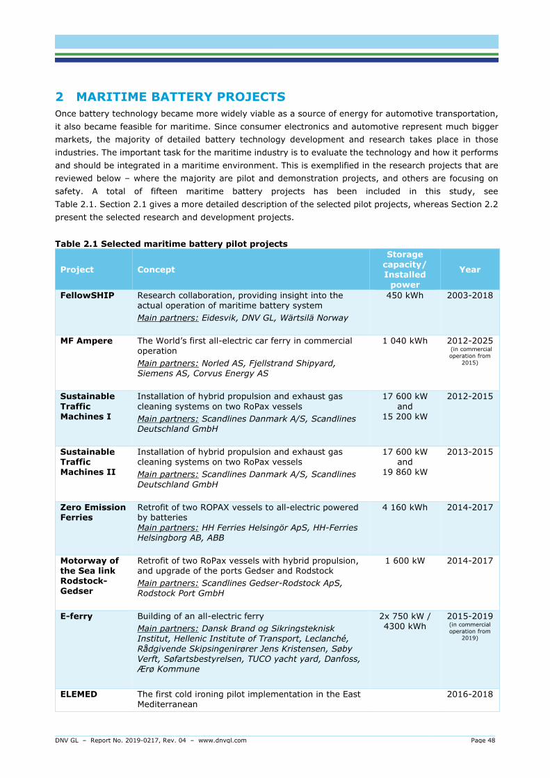
DNV GL – Report No. 2019-0217, Rev. 04 – www.dnvgl.com Page 48
2 MARITIME BATTERY PROJECTS Once battery technology became more widely viable as a source of energy for automotive transportation, it also became feasible for maritime. Since consumer electronics and automotive represent much bigger markets, the majority of detailed battery technology development and research takes place in those industries. The important task for the maritime industry is to evaluate the technology and how it performs and should be integrated in a maritime environment. This is exemplified in the research projects that are reviewed below – where the majority are pilot and demonstration projects, and others are focusing on safety. A total of fifteen maritime battery projects has been included in this study, see Table 2.1. Section 2.1 gives a more detailed description of the selected pilot projects, whereas Section 2.2 present the selected research and development projects.
Table 2.1 Selected maritime battery pilot projects
Project Concept
Storage capacity/ Installed
power
Year
FellowSHIP Research collaboration, providing insight into the actual operation of maritime battery system
Main partners: Eidesvik, DNV GL, Wärtsilä Norway
450 kWh 2003-2018
MF Ampere The World’s first all-electric car ferry in commercial operation
Main partners: Norled AS, Fjellstrand Shipyard, Siemens AS, Corvus Energy AS
1 040 kWh 2012-2025 (in commercial operation from
2015)
Sustainable Traffic Machines I
Installation of hybrid propulsion and exhaust gas cleaning systems on two RoPax vessels
Main partners: Scandlines Danmark A/S, Scandlines Deutschland GmbH
17 600 kW and
15 200 kW
2012-2015
Sustainable Traffic Machines II
Installation of hybrid propulsion and exhaust gas cleaning systems on two RoPax vessels
Main partners: Scandlines Danmark A/S, Scandlines Deutschland GmbH
17 600 kW and
19 860 kW
2013-2015
Zero Emission Ferries
Retrofit of two ROPAX vessels to all-electric powered by batteries Main partners: HH Ferries Helsingör ApS, HH-Ferries Helsingborg AB, ABB
4 160 kWh 2014-2017
Motorway of the Sea link Rodstock-Gedser
Retrofit of two RoPax vessels with hybrid propulsion, and upgrade of the ports Gedser and Rodstock
Main partners: Scandlines Gedser-Rodstock ApS, Rodstock Port GmbH
1 600 kW 2014-2017
E-ferry Building of an all-electric ferry
Main partners: Dansk Brand og Sikringsteknisk Institut, Hellenic Institute of Transport, Leclanché, Rådgivende Skipsingenirører Jens Kristensen, Søby Verft, Søfartsbestyrelsen, TUCO yacht yard, Danfoss, Ærø Kommune
2x 750 kW / 4300 kWh
2015-2019 (in commercial operation from
2019)
ELEMED The first cold ironing pilot implementation in the East Mediterranean
2016-2018

DNV GL – Report No. 2019-0217, Rev. 04 – www.dnvgl.com Page 49
Main partners: Hellenica Centre for Marine Research, Cyprus Ports Authority, Killini Port Authority, Protasis S.A., Spanopoulos Group, Piraeus Port Authority, National Tech. University of Athens, Hydrus Group, Port of Koper, Lloyd’s Register
Yara Birkeland
World’s first fully electric and autonomous container ship
Main partners: Kongsberg Group, Marin Teknikk, Enova, Norwegian Maritime Authority, Kystverket, Ports of Grenland and Larvik, Herøya Industripark, Yara, SINTEF
7 - 9 000 kWh 2012-2020
Port-Liner World’s first inland waterway container barges to sail from European ports with full electrical propulsion
Main partners: GVP Group of Logistics, Werkina Wekendam, Willemsen Interieurbouw, H2-Industries, Tesvolt, Van Oossanen Naval Architects
1 600 kW 2017-2019
SuperGreen Deployment of alternative fuels infrastructure
Main partners: Ocean Finance Ltd, Public Gas Corporation S.A., S.G.V.L Supergreen Venture Ltd
TBA 2019-2021
BB-Green Development and launch of an innovative waterborne transport solution
Main partners: Lloyd’s Register EMEA, DIAB AS, Aqualiner, Amerjac Projects Ltd, Carbonia Composites AB, SSPA Sweden AB
200 kWh 2011-2014
Table 2.2 Selected safety research and development projects Project Concept Year
SafeLiLife Evaluation of battery safety properties and interrelation with degradation and ageing
Main partners: ABB, DNV GL, Rolls Royce, FMC Subsea, ZEM, IFE (Institute for Energy Technology), FFI (Norwegian Defense Research Establishment), NTNU (Norwegian University of Science and Technology, Dep. Of Chemistry), HiST (Sør-Trøndelag University College)
2010-2016
Maritime Battery Safety JDP
Testing and analysis of battery safety properties to generate knowledge needed to increase efficiency of regulation
Main partners: DNV GL, FFI, NMA, DMA, MARAD, Corvus, Leclanche, Super B, Scandlines, Stena, Damen, ABB, Kongsberg, FIFI4MARINE, Nexceris, Marioff
2017-2019
MoZEES Develop materials for environmentally friendly energy technologies for transportation
Main partners: IFE, SINTEF, NTNU, UiO, TØI, FFI, HSN, Akershus County Council, Sør Trøndelag fylkeskommune, Statens Vegvesen, Enova, Jernebanedirektoratet, Port of Oslo, Kystverket, ABB, AGA, ASKO, Baldur, BASF, Bellona, REEC, Dynatec, Hexagon Composites, Johnson Matthey Fuel Cells, VerPoTech, Maritim Forening Sogn og Fjordane, Elkem, Miba, Nel, Graphene Batteries, ZEM, Saft, ZEG Power, DNV GL, Selfa Arctic, Lloyd’s Register, Grenland Energy, Unibuss, PBES
2017-2024

DNV GL – Report No. 2019-0217, Rev. 04 – www.dnvgl.com Page 50
2.1 Descriptions of selected pilot projects In this section, the selected pilot projects listed in Table 2.1 in the previous section are described in more detail. This section covers the background and objectives of the various projects, as well as the technical details (battery type cell chemistry, technology and storage capacity) where applicable and the results from the project.
2.1.1 FellowSHIP BACKGROUND AND OBJECTIVES
The FellowSHIP was a successful research collaboration between Eidesvik, Wärtsilä Norway and DNV GL. The project aimed to explore the use of battery, hybrid and fuel cell technology in the maritime industry. It took place from 2003 to 2018 and involved four main phases. The first two phases focused on fuel cell technology, whereas phase III and IV focused on lithium-ion battery technology.
In the first phase (2003-2005), a feasibility study was carried out, investigating the use of Fuel Cells in shipping. The feasibility study resulted in the development of the first classification rules for maritime FCs. Phase one also involved the development of a basic design for hybrid fuel cell power pack.
The second phase (2006-2010) was about the development, designing, building, testing and qualifying the stand-alone fuel cell power pack integrated in a ship. This involved the installation of a 320 kW Molten Carbonate Fuel Cell (MCFC) for auxiliary power on board the offshore supply vessel (OSV) Viking Lady. Figure 2.1 shows a picture of the Viking Lady. This phase focused on the on-board testing and measurements of the fuel cell installation. The vessel was built in 2009 with dual-fuel engines and conventional diesel electric propulsion. Between 2009 and 2013, the energy system of Viking Lady was gradually hybridized with full-scale energy conversion and storage technology.
The third phase (2011-2014) was initiated in 2011, investigating how the introduction of energy storage (Li-Ion battery pack) in the power system can reduce emissions and improve efficiency, performance and safety. This involved the conversion of the propulsion system of the Viking Lady to a battery hybrid-electric propulsion system, including the installation of a 442 kWh capacity lithium-ion battery to the power train. The main focus of this phase was the development of hybrid design concepts and on-board testing and measurements of the battery system.
The main purpose of phase four was to accelerate the development and update of marine hybrid battery systems. During this phase, the robustness and reliability of the hybrid system and further optimize the performance of the system, was investigated. The main focus in this phase was monitoring of real-life operational conditions and performance, to prove reliability, safety and operational benefits of the battery system. Another important aspect of this phase was on performance optimization and long-term performance and lifetime of the battery technology. The fourth phase also focused on further improvement of operations and control strategy for the hybrid-energy and propulsion systems. The Complex Ship Systems Modelling and Simulation (COSSMOS), a DNV GL in house modelling and simulation platform, played a key role in this phase of the project. Figure 2.2 shows the COSSMOS model of the battery-hybrid propulsion system on board the Viking Lady. The advanced COSSMOS simulations helped identify promising power management strategies to maximise the energy gains while ensuring the vessel’s safety and operational capabilities (DNV GL, 2015). Furthermore, to combine real-life measurements with advanced simulation models turned out to be valuable and resulted in deeper understanding of a maritime battery-hybrid propulsion system. Figure 2.3 illustrates the methodology of using COSSMOS to quantify savings, compare and optimise the operations of Viking Lady.

DNV GL – Report No. 2019-0217, Rev. 04 – www.dnvgl.com Page 51
The fourth phase also involved hybrid control strategy optimisation and COSSMOS power system simulation, ship simulation to investigate improved dynamic and failure handling capabilities, CFD simulations to optimise transit operations, battery degradation, state of health (SoH) monitoring and maintenance data analysis (DNV GL, 2015).
Figure 2-1 The offshore supply vessel, Viking Lady, which was used as the research vessel in the FellowSHIP research collaboration
Figure 2-2 COSSMOS model of the battery-hybrid propulsion system on board the Viking Lady (DNV GL, 2015)

DNV GL – Report No. 2019-0217, Rev. 04 – www.dnvgl.com Page 52
Figure 2-3 Methodology for using COSSMOS to quantify savings, compare and optimize the operations of Viking Lady (DNV GL, 2015)
TECHNICAL DETAILS
Table 2.3 gives an overview of the main technical details of the Viking Lady. The battery installed on board is a lithium-ion battery with storage capacity of 450 kWh from Corvus Energy. The cell chemistry of the battery is NMC. The battery acts as am energy buffer covering the intense demands that occur especially during DP and standby operations.
Table 2.3 Main technical details of the offshore supply vessel, Viking Lady Technical details Unit Viking Lady Ship type - Offshore supply vessel Length m 92.2 Beam m 21.0 Depth m 9.6 Battery storage capacity kWh 450 Installed battery power kW 900 Cell chemistry - NMC
KEY ROLE OF THE BATTERY SYSTEM
The Viking Lady was the first merchant ship to be powered by a battery-hybrid propulsion plant. The installation of a battery combined with fuel cell and LNG, reduced the fuel consumption, enhanced vessel performance, noise reduction and safety improvement. An annualised projection of the results showed, for all operational modes (transit, DP, standby, harbour) of the vessel, up to 25 % NOx reduction, up to 30% GHG emissions reduction, as well as up to 15% reduction in fuel consumption. This is illustrated in the diagrams in Figure 2.4.
Overall, the FellowSHIP project provided valuable insight into the actual operation of maritime battery system. The key results were; reduced emissions, improved machinery utilization and flexibility and reduced maintenance cost involving fewer engine running hours, less running on low loads, longer intervals between planned maintenance and less planned maintenance.

DNV GL – Report No. 2019-0217, Rev. 04 – www.dnvgl.com Page 53
Figure 2-4 Sea trials: hybrid system performance in DP mode during calm weather (left) and bad weather (right) (DNV GL, 2015)
2.1.2 MF Ampere BACKGROUND AND OBJECTIVES
In 2012, the Norwegian Public Roads Administration issued a tender for a competitive dialog on the development of a new technology for ferries to operate across one of the Norwegian fjords. The tender required at least 20 percent improved energy- and environment efficiency.
The result was MF Ampere, which became the world’s first large-size all-electric battery-powered car ferry. The ferry has operated on the fixed route between Lavik and Oppedal in Sognefjorden, Norway, since it came into operation in January 2015.
The vessel is owned by the ferry operator, Norled, and was built at the Norwegian shipyard Fiskerstrand.
Figure 2-5 The world's first large-size all-electric battery-powered car ferry, MF Ampere
TECHNICAL DETAILS
Table 2.4 gives an overview of the main technical details of the ferry. The ferry is equipped with 10 tons of batteries with capacity of two times 500 kWh, as well as a quick charger on shore with the capacity of 300 kWh. The ferry uses approximately 200 kWh per crossing. The batteries are placed in rack in to separate battery rooms, one of each for the front and after propulsion machinery.
The schedule of the ferry involves 20 minutes crossing, 10 minutes quick charging in each ferry terminal and a full charge overnight. The charging system contains of two Stemmann pantograph and Cavotec plug. When the ferry is approaching the quay, GPS signals are sent from the ferry to the Cavotec Vacuum Mooring, which suck the ferry, with a sucking power of 20 tonnes.

DNV GL – Report No. 2019-0217, Rev. 04 – www.dnvgl.com Page 54
Table 2.4 Main technical details of the all-electric ferry, MF Ampere Technical details Unit MF Ampere Ship type - RoPax Capacity cars, pax 120, 350 Length m 80.8 Beam m 20.8 Battery storage capacity kWh 1000 Cell chemistry - NMC
Figure 2-6 MF Ampere Single Line Diagram (Corvus Energy, 2016)
KEY ROLE OF THE BATTERY SYSTEM
The batteries have resulted in a operating cost reduction of about 80 %, compared to operating the same route running on diesel. This corresponds to about 1 million litre diesel, which is equivalent to more than 8 thousand tonnes of CO2 since the ferry was put into operation.
In the beginning the ferry was experiencing some difficulties related to the transferred effect from shore to the ferry, which resulted in some ferry crossings being cancelled. The local power grid was not dimensioned to deliver the required power for the ferry. The solution became to have a battery bank on each side of the fjord, which is charged by the normal high voltage grid. During 2018, the ferry has 34 crossings a day, and has had a regularity of 98.7%, where most of the deviations have been caused by the weather and wind together with some technical challenges (Norled, 2018).
MF Ampere has received a lot of international attention. The building of MF Ampere har shown that greener and more environmentally friendly solutions can also be cost-efficient. This project also shows that is extremely important to have the authorities closely involved, resulting in good collaborations, understanding and insight in possible solutions and the bigger picture.

DNV GL – Report No. 2019-0217, Rev. 04 – www.dnvgl.com Page 55
2.1.3 Sustainable Traffic Machines I & II BACKGROUND AND OBJECTIVES
“PRINSESSE BENEDIKTE” AND “SCHLESWIG HOLSTEIN”
The first of the Sustainable Traffic Machines projects involved the installation of hybrid propulsion and exhaust gas cleaning systems on two of Scandlines RoPax vessels; Prinsesse Benedikte and Schleswig Holstein. The vessels operate on the route between Rødby in Denmark and Puttgarden in Germany. Prinsesse Benedikte was the world’s largest hybrid ferry when the retrofit was completed in 2013.
The aim of the project was to combine the propulsion and exhaust gas cleaning technologies to specific requirements both of standardized ferry operations and environmental regulations (European Commission, 2014).
The project started in January 2012 and was ended in December 2015.
Figure 2-7 Prinsesse Benedikte to the left and Schleswig Holstein to the right.
“PRINS RICHARD” AND “DEUTSCHLAND”
The Sustainable Traffic Machines II, “The green link between Scandinavia and Conventional Europe”, were initiated to meet the IMO’s Sulphur Emission Control Area (SECA) regulations that entered into force on January 1, 2015 for ships operating in the Baltic Sea, in addition to the EU’s stricter sulphur limits for marine fuels. The project involved the installation of state-of-the-art technology, hybrid propulsion on “Prins Richard” and “Deutschland”, the sister vessels of “Prinsesse Benedikte” and “Schleswig Holstein”, respectively.
The two RoPax vessels have been hybrid since 2014.

DNV GL – Report No. 2019-0217, Rev. 04 – www.dnvgl.com Page 56
Figure 2-8 Prins Richard to the left and Deutschland to the right.
TECHNICAL DETAILS
Table 2.5 gives an overview of the main technical details of the four Scandlines RoPax vessels. The installed power on board Deutschland and Schleswig Holstein is 17600 and 19860 kW, respectively. The installed power on board Prins Richard is 19860 kW and on board Prinsesse Benedikte is 15200 kW. The vessels are equipped with NMC batteries. The storage capacity of the batteries is 1600 kWh for Deutschland and Schleswig Holstein and 2600 kWh for Prinsesse Benedikte and Prins Richard. The batteries were installed on board the vessels in 2013.
The distance between Rødby and Puttgarden is 18 kilometres. The charging of the batteries takes about 30 minutes, powered by generators on board the vessels.
Table 2.5 Main technical details of the four Scandlines RoPax vessels; Prinsesse Benedikte, Prins Richard, Schleswig Holstein and Deutschland
Technical details Unit Prinsesse Benedikte/ Prins Richard
Schleswig Holstein/ Deutschland
Ship type - RoPax RoPax Capacity cars, pax 300, 900 Length M 142.0 142.0 Beam M 23.2 24.8 Depth M 14.1 8.5
Installed power kW 15200/19860 17600 Battery storage capacity kWh 2600 1600
Battery chemistry - NMC NMC
KEY ROLE OF THE BATTERY SYSTEM
The batteries are used for hybrid propulsion and reduces the fuel consumption of up to one million kilograms per year. Additionally, the battery installation increases the safety and reliability of the vessels, including the prevention of blackouts.

DNV GL – Report No. 2019-0217, Rev. 04 – www.dnvgl.com Page 57
2.1.4 Zero Emission Ferries BACKGROUND AND OBJECTIVES
The project Zero Emission Ferries involves the conversion of two existing Scandlines RoPax vessels from marine gas oil to plug-in all electric powered by batteries. The two ferries, Tycho Brahe and Aurora, operate between Helsingör in Denmark and Helsingborg in Sweden (Forsea, 2018).
These two ports are located in densely populated areas and the installation of batteries will contribute to improve the air quality of the two ports, as well as reduce noise.
Figure 2-9 Tycho Brahe and Aurora.
TECHNICAL DETAILS
Table 2.6 gives an overview of the main technical details of the two RoPax vessels. Each vessel will have a battery storage capacity of 4160 kWh, corresponding to the same power as 70 electric cars. The batteries are installed in four 32-foot containers on top of the ship alongside two deckhouses, which contains transformers, converters and cooling systems for the batteries. The four diesel engines already installed on boars will remain on the ship. They will function as a backup after the conversion to electric power.
Table 2.6 Main technical details of the Scandlines vessels Tycho Brahe and Aurora
Technical details Unit Tycho Brahe/Aurora Ship type - RoPax
Passenger capacity Pax, cars 1100/1250, 238/240 Length m 111.0 Beam m 28.0 Depth m 5.5
Battery storage capacity kWh 4160
The vessels sailing schedule involves the departure every 15 minutes. Every time the ferries are at port, the batteries must be charged with about 1200 kWh. The charging in ports takes about 5-9 minutes, which will therefore not impact the schedule of the vessels. A fully automatic laser-guided robotic arm is handling the charging of the batteries in port and connects the batteries to the grid (see Figure 2.10 for illustration). The robot orients itself using laser scanning. This technology is mounted in towers that are more than 10 metres high.

DNV GL – Report No. 2019-0217, Rev. 04 – www.dnvgl.com Page 58
Figure 2-10 Illustration of how the power is connected to the vessels while in port (PBES, 2016)
KEY ROLE OF THE BATTERY SYSTEM
The two ferries, Tycho Brahe and Aurora, became the world’s first battery-powered ferries on a high intensity route. The ferries were converted to battery power, which has enabled 50% reduction in overall emissions (Forsea, 2018).
2.1.5 Motorway of the Sea link Rodstock-Gedser BACKGROUND AND OBJECTIVES
The aim of the project was to upgrade and to enlarge the maritime capacity of the Rostock – Gedser route. This involved the conversion to ensure environmental and efficiency compliance
The activities included the equipment of the RoPax vessels “MS Berlin” and “MS Copenhagen” with hybrid propulsion and to do berth adaption and terminal improvements of the two ports, Rostock and Gedser. The two ferries have been in operation since 2016.
Figure 2-11 The hybrid ferries, MV Berlin and MV Copenhagen

DNV GL – Report No. 2019-0217, Rev. 04 – www.dnvgl.com Page 59
TECHNICAL DETAILS
Table 2.7 gives an overview of the main technical details of the two vessels. The vessels have a battery storage capacity of 1.6 MW. The cell chemistry of the batteries is NMC.
Table 2.7 Main technical details of the RoPax vessels; MS Berlin and MS Copenhagen
Technical details Unit MS Berlin/ MS Copenhagen Ship type - RoPax Capacity cars, pax 460, 1300 Length M 169.5 Beam M 25.4 Battery storage capacity kWh 1600 Cell chemistry - NMC
KEY ROLE OF THE BATTERY SYSTEM
The batteries installed on board the two ferries are used for hybrid propulsion. This conversion was part of Scandlines’ ambitious environmental strategy.
2.1.6 E-Ferry BACKGROUND AND OBJECTIVES
The E-ferry project is a four-year innovation project, funded by European Commission Horizon 2020 with the purpose of designing, building and demonstrating an all-electric, middle sized car and passenger ferry.
The aim of the project is to promote energy efficiency, CO2 neutral and zero emission ship transportation for island routes and in coastal waters, both within and without Europe. The E-ferry project was an initiative towards the realization of the Danish Green Ferry Vision.
The car and passenger ferry will be designed to operate on longer distances than previously seen, involving more than five nautical miles for electric drive train ferries. The distance from Soeby to Fynshav and from Soeby to Faaborg is about 10 nautical miles.
Some of the main objectives of the E-ferry project are:
- To build a vessel that has an energy efficient design, using lightweight equipment and materials, and uses state-of-the-art electric only systems with automated high-power charging system.
- To obtain approval of the use of carbon fibre reinforced (CFR) composite modules in the superstructure of the E-ferry.
- To reduce the yearly CO2 emissions by about 200 tonnes, NOx by 41.5 tonnes, SOx by 1.4 tonnes and particulates by 2.5 tonnes after the ferry is put into operation.

DNV GL – Report No. 2019-0217, Rev. 04 – www.dnvgl.com Page 60
Figure 2-12 The fully electric powered green ferry, E-ferry
The project officially started in June 2015. Originally, the plan was to have the design phase last for a year, followed by the building phase also planned to last for a year, and then two years of demonstrations. As both the design and building phases were extended, the ferry is expected to be put in operation during the first quarter of 2019.
TECHNICAL DETAILS
Table 2.8 gives an overview of the main technical details of the E-ferry. The battery system is customized for the ferry. To keep the operational temperature stable, the batteries are water cooled. The installed power of the E-ferry is 2 x 750 kW, with a battery storage capacity of 4,3 MWh. The battery pack peak charging power and shore charging connection will be up to 4 MW (E-ferry, 2018), allowing short port stays.
The ferry is planned to charge only while in Søby, which require the ferry to sail more than 22 nautical miles, before charging. It is expected that about one third of the ferry’s daily energy demand is charged

DNV GL – Report No. 2019-0217, Rev. 04 – www.dnvgl.com Page 61
during the night, while the ferry is in Søby, whereas the rest is charged while the ferry is in Søby during the daily operation (Ærø Kommune, 2018).
The ferry has a capacity of almost 150 passengers during the winter and close to 200 passengers during the summer. The E-ferry will operate in high speed up to 14,5 knots and will be able to operate in ice conditions up to 15-20 centimetres. The crossing from Søby to Fynshavn will take about 55 minutes, which is a reduction of 15 minutes. The vessel is designed as an optimized mono-hull, which reduces the propulsion resistance and results in both the total energy consumption and crossing time being significantly lower, compared to a double ended ferry.
The E-ferry project is an EU supported development project with the aim of designing, building and demonstrating a 100% electrically driven passenger and car ferry. The E-ferry Ellen is in many ways a pioneer within her field, which is especially evident by her reach. She can sail up to 22 nautical miles between charges which is 7 times farther than previously possible for an electric ferry. The groundbreaking project is in its final stages, where the electric ferry is put into normal operation and needs to demonstrate that it is possible to complete up to 7 return-trips per day, between Søby and Fynshav. Time schedules are available at the homepage of Ærøfærgerne, where bookings can also be made, see www.aeroe-ferry.dk.
For further information about the E-ferry project, see: www.e-ferryproject.eu
Table 2.8 Main technical details of the E-ferry
Technical details Unit E-ferry Ship type - Car/passenger ferry Capacity cars, pax 31, 147/196 Length M 59.4 Beam M 13.4 Depth M 3.7
Installed power kW 1500 Battery storage capacity kWh 4300
Cell chemistry - NMC
KEY ROLE OF THE BATTERY SYSTEM
The batteries are used for all-electric operation, to choose an environmentally friendly propulsion option. The project intends to collaborate with power companies and wind power producers to ensure that the charged power does not harm the environment. The ferry will then reduce about 2000 tonnes of CO2, 41 500 tonnes NOx, 1,35 tonnes of SOx, as well as 2,5 tonnes particles per year.
By operating all-electric, the noise and vibrations are reduced, compared to operating with a combustion engine. Additionally, the slim and optimised hull shape secure a low heel and booging movement from the ferry at speed. This significantly reduces the environmental impact on coastal and wildlife, locally.
2.1.7 ELEMED BACKGROUND AND OBJECTIVES
Electrification in the Eastern Mediterranean, the ELEMED project, is a green initiative that will establish the Eastern Mediterranean’s first operational on-shore power connection. It is a cross-European maritime network looking at macro-regional strategies for Adriatic-Ionian Seas.
The aim of the project is to study matters related to the development of low-carbon, resource-efficient cold ironing infrastructure in Mediterranean ports. The ports involved in the project are located in three of

DNV GL – Report No. 2019-0217, Rev. 04 – www.dnvgl.com Page 62
the EU member states; Greece (Port of Piraeus and Port of Killini), Cyprus (Port of Limassol) and Slovenia (Port of Koper) (Elemed, 2018).
The main activities of the project involve:
- The formulation of a regulatory framework for use of electricity as the marine fuel in the Eastern Mediterranean.
- The establishment of technical requirements for cold ironing installations in ports.
- The specification of technical requirements for electrification in shipping.
- The development of sustainable financing instruments for port/vessel infrastructure development.
- The installation of the first on shore power supply system in the Eastern Mediterranean area at the Port of Killini in Greece.
The implementation schedule started in April 2016 and lasted until March 2018.
Figure 2-13 Illustration of the Electrification in the Eastern Mediterranean (ELEMED) project (Elemed, 2018)
TECHNICAL DETAILS
The realisation of this project will involve the first cold ironing pilot implementation in the East Mediterranean. The port stay will need 500 kVA, and there are projected four shore connections and one electric bunkering position.
KEY ROLE OF THE BATTERY SYSTEM
The project targets the introduction of cold ironing and hybrid ships across the Eastern Mediterranean Sea corridor. The environmental benefits of the projects involve reduction of emissions in the port and surrounding areas, improvement of life quality due to the reduction of local emissions, improvement of port competitiveness, preparation of port for accommodating hybrid zero-emission vessels.

DNV GL – Report No. 2019-0217, Rev. 04 – www.dnvgl.com Page 63
2.1.8 Yara Birkeland BACKGROUND AND OBJECTIVES
The Yara Birkeland project is a cooperation between Yara and Kongsberg. The project was initiated in an effort to improve the logistics at Yara’s fertilizer plant in Porsgrunn.
The Yara Birkeland project aims at moving goods from land to sea in an environmentally friendly way to reduce the local noise and dust emissions, get safer roads and reduce emissions. The project involves the design, construction and operation of a full-electric battery powered container vessel, transporting fertiliser from Yara’s factory at Herøya to the ports at Breivik and Larvik.
The first phase of the Yara Birkeland project is the implementation of a detachable bridge with equipment for manoeuvring and navigation. This bridge will be removed when the vessel is ready for autonomous operation.
The loading, discharging and mooring will be done automatically. Electric cranes and equipment will be used for the loading and discharging operations. The vessel will not be equipped with ballast tanks, as the battery pack
It is a collaboration project between several key companies in the maritime industry, mainly from the Norwegian maritime cluster. Some of them are listed below.
- Yara is the buyer of the vessel. As a leading global fertilizer company with a mission to feed the world and protect the planet, has invested in the Yara Birkeland project to reduce emissions and make the production as environmentally friendly as possible.
- Kongsberg is responsible for the development and delivery of key enabling technologies including the sensors and integration required for remote and autonomous vessel operation, as well as the electric drive, battery and propulsion control system.
- Marin Teknikk, a Norwegian ship designer, has made the design, which was finalised in 2017.
- SINTEF Ocean in Trondheim has created and tested the model in their model towing tank in Trondheim, Norway.
- Vard Brevik will be the delivery shipyard of the vessel, which is planned to be delivered in the beginning of 2020, gradually moving from manned operation to fully autonomous operation by 2022.
One of the main challenges of the project has been that there were no regulations dealing with autonomous ships. In an early phase of the project, established good cooperation were established with both the Norwegian Coastal Administration and the Norwegian Maritime Authorities to update the regulations. The work done to adapt legislation and regulations has been an important and prerequisite to succeed with such a project.
DNV GL has developed the necessary rules (DNV GL, 2018). Yara Birkeland will be the testbed vessel for the new guidelines. The new guidelines cover navigation, vessel engineering, remote control centres and communications, with particular emphasis given to cyber security and software testing. It is aimed at helping owners seeking to implement new technologies with a process toward obtaining flag state alternative design requirements. For new technologies the guideline can also be used to obtain an approval in principle by suppliers.

DNV GL – Report No. 2019-0217, Rev. 04 – www.dnvgl.com Page 64
Figure 2-14 The zero emission, all-electric, battery-powered container vessel, Yara Birkeland
Figure 2-15 Model of the final design of the autonomous and fully electric container vessel, Yara Birkeland, in the test tank facility at SINTEF Ocean (Kongsberg Maritime, 2017)
Figure 2-16 Map showing the location of the ports at Herøya, Brevik and Larvik

DNV GL – Report No. 2019-0217, Rev. 04 – www.dnvgl.com Page 65
TECHNICAL DETAILS
Table 2.9 gives an overview of the main technical details of the fully electric and autonomous container vessel, Yara Birkeland. The vessel will be a 120 TEU (Twenty-foot Equivalent Units) open top container ship. The propulsion and manoeuvring of the vessel will be handled by an electrical system consisting of a battery package of 7-9 megawatt hours, two electrical azipods and two tunnel thrusters.
The autonomous ship will sail within 12 nautical miles from the coast, between 3 ports in southern Norway. By the use of GPS, radars, cameras and sensors, the vessel will be able to navigate around other ship traffic and maneuver to and from port on its own. To ensure safety, three centers with different operational profile are planned to handle all aspects of operation. These centers will handle emergency and exception handling, condition monitoring, operational monitoring, decision support, surveillance of the autonomous ship and its surroundings and all other aspects of safety.
Table 2.9 Main technical details of the fully electric and autonomous container ship, Yara Birkeland
Technical details Unit Yara Birkeland Ship type - Container ship Capacity TEU 120 Length M 79.5 Beam M 14.8 Depth M 6.0 Battery storage capacity kWh 7000-9000 Cell chemistry -
KEY ROLE OF THE BATTERY SYSTEMS
The vessel was conceived primarily on the foundation of being the first autonomous vessel. A key aspect of this concept is the use of battery power. This is because the maintenance requirements for batteries are significantly lower than diesel engines and this is necessary for enabling operation without a crew, autonomously.
The vessel will reduce about 700 tonnes of CO2 per year, but the main benefit of the project is that the local areas will have less dust and NOx emissions. The use of a vessel for transportation will also improve road safety by removing up to 40000 truck journeys in populated urban areas (Kongsberg Maritime, 2017). When the project was initiated, there was no regulations for autonomous ship traffic.
2.1.9 Port-Liner BACKGROUND AND OBJECTIVES
The Port Liner is an inland shipping initiative, aimed at promoting the uptake zero emission shipping based on electric propulsion (European Commission, 2018).
The first step of the project is to build six inland waterway container vessels, with full electrical propulsion. They will be the world’s first electric container barges to sail from European ports. The vessels will be equipped with 1.6 MW batteries, which are containerised in E-Powerboxes. The E-Powerboxes will be swapped at port terminals for charging.

DNV GL – Report No. 2019-0217, Rev. 04 – www.dnvgl.com Page 66
Figure 2-17 Rendering Illustration of the Port-Liner vessel
TECHNICAL DETAILS
Table 2.10 gives an overview of the main technical details of the Port-Liner inland waterway container vessels. The vessels will have four E-Powerboxes each, which will be stored under the wheelhouse. The E-Powerbox capacity will give the vessels an action radius of 14 hours (Port-Liner, 2018). The action radius makes it possible for the vessels to cover corridors such as Rotterdam-Antwerp-Duisburg.
As the vessels are going to be powered by the E-Powerboxes, there is no need for a traditional engine room. This increases the container capacity of the vessels with 8%, resulting in a total container capacity of 280 TEU. In terms of container lengths this corresponds to a length of 14 twenty feet containers or seven containers of forty feet. The vessel will have an adjustable wheelhouse, involving load and route flexibility. In terms of stability, the vessel can be loaded with up to five containers in height. Regarding the route, some of the inland water ways involve limitations in terms of bridge heights.
Table 2.10 Main technical details of the Port-Liner inland waterway container vessels
Technical details Unit Port-Liner vessels Ship type - Container Capacity TEU 280 Length m 110.0 Beam m 11.5
Battery storage capacity kW 1600

DNV GL – Report No. 2019-0217, Rev. 04 – www.dnvgl.com Page 67
KEY ROLE OF THE BATTERY SYSTEM
Batteries are used for all-electric operations both in port and in transit. The vessels are expected to replace 23000 trucks that are mainly running on diesel, which can lead to a reduction of approximately 18000 tonnes CO2 per year.
2.1.10 SuperGreen BACKGROUND AND OBJECTIVES
SuperGreen is a collaboration between Ocean Finance Ltd and Public Gas Corporation SA. SuperGreen involves the implementation of a sustainable and green transport system in Greece, aimed at introducing cost and time efficient, eco-friendly transportation (Ocean Finance, 2018). The idea of the project came to meet the new mode of coastal shipping and tourist travel.
The project’s objectives are:
- To construct and put in operation three all-electric commuter vessels and a hybrid (LNG/electric) catamaran vessel, to eventually provide three medium-sized type electric buses and one regular type electric bus for the users of the electric vessels
- To construct and put operation a hybrid (LNG/electric) catamaran to provide on Piraeus Port the means for LNG bunkering and battery charging.
- Two LNG bunkering tanker trucks, in addition to various mobile electricity storage systems to supply all vessels.
- One LNG/CNG fuelled truck for autonomous management of all mobile equipment.
- Multimodal integration electronic platform to facilitate the booking of travel arrangements.
The implementation of the project is planned to be from January 2019 to April 2021.
Figure 2-18 Illustration of the SuperGreen projects (INEA, 2018) and the composite cryogenic tanks

DNV GL – Report No. 2019-0217, Rev. 04 – www.dnvgl.com Page 68
TECHNICAL DETAILS
The three all-electric vessels will be battery powered. They are to be operated in Argosaronics Gulf and to be charged in port, both Port of Aegina and Piraeus Port, before the departure of each route. The three vessels will be all composite. As the project will start in January 2019, all details of the project are not decided. The cell chemistry of the battery will be either NMC or LTO. They will also investigate the technology of lithium air or aluminium batteries.
The two catamarans will be all-composite and hybrid configuration. LNG fuelled gas turbines will be installed for propulsion, whereas batteries will be installed for serving hotel and ice optimization.
KEY ROLE OF THE BATTERY SYSTEM
The LNG fuelled catamaran will be the world’s first vessel installed with an innovative, all-composite, ultralight cryogenic tank.
The project is facing some challenges as it is introducing all composite. The ultralight vessels will have high speed, all electric and requiring fast charging configurations (less than 30 minutes). The LNG fuelled vessels will be of high speed, have space industry originated cryogenic tank. Overall the projects involve the implantation of high energy profile grid requests (1-2 MVA).
2.1.11 BB-Green BACKGROUND AND OBJECTIVES
The BB-Green (Battery-powered Boats, providing Greening, Resistance reduction, Electric, Efficiency and Novelty) is a collaborative R&D project (BB Green, 2018).
The BB-Green objectives involved the development and launch of a new, innovative and competitive waterborne transport solution, which presented a step change in public service offered. The BB-Green emits zero greenhouse gases and introduced a climate friendly travel choice.
Figure 2-19 BB-Green battery powered ship

DNV GL – Report No. 2019-0217, Rev. 04 – www.dnvgl.com Page 69
TECHNICAL DETAILS
The BB-Green is an all-electric vessel. The vessel has a tailor made 200 kWh Lithium-ion titanate turnkey battery energy storage system provided by Leclanché (BB Green, 2018). The charging of the battery takes less than 20 minutes to about 95% SOC, with the ability to reach to 15000 full cycles. To optimize the operation and cycle life of the battery, the battery is connected to the cloud, storing and processing all the data. The length of the vessel is 20 metres, with a beam of 6 metres.
2.2 Descriptions of Selected Safety Projects 2.2.1 SafeLiLife BACKGROUND AND OBJECTIVES
Life and safety for Lithium-ion batteries in Maritime conditions (SafeLiLife) was a public funded research project from 2012 to 2016. The project focused on safety of batteries by obtaining test data and also by incorporating the aspect of degradation. The purpose of the project was to help the maritime industry take environmentally and cost-efficient decisions for future ships (IFE, 2014).
The objective was to build in-depth knowledge on expected battery life and safety for selected Lithium-ion battery chemistries subject to maritime conditions (FFI, 2017). The project included the following activities:
- Accelerated battery life testing
- Thermodynamic and electrochemical characterization
- Battery safety and failure monitoring
- Thermal properties and modelling
- Battery life modelling
- Lithium-ion battery decay mechanisms analysis
The SafeLiLife project included a test plan with abuse tests aiming at making safety recommendations for lithium-ion cells, both for new and aged cells. Furthermore, the project evaluated how degradation mechanisms might also affect the safety of lithium-ion cells. For both new cells and cyclic aged cells, analysis and thermal tests were performed to provide results that conform to what was considered a worst-case scenario.
TECHNICAL DETAILS AND RESULTS
Tests were conducted at cell level. The project focussed on cycling and degradation behaviour characterization as well as safety properties. Safety properties were studied primarily through Accelerating Rate Calorimetry (ARC) to evaluate the differences between cell technologies. One interesting result was that cells aged at low temperatures were shown to potentially have reduced thermal stability.
PARTNERS
ABB, DNV GL, Rolls Royce, FMC Subsea, ZEM, IFE (Institute for Energy Technology), FFI (Norwegian Defense Research Establishment), NTNU (Norwegian University of Science and Technology, Dep. Of Chemistry), HiST (Sør-Trøndelag University College)

DNV GL – Report No. 2019-0217, Rev. 04 – www.dnvgl.com Page 70
2.2.2 Maritime Battery Safety Joint Development Project BACKGROUND AND OBJECTIVES
With regard to battery safety there is an immense amount of research and development that would be required to fully technically understand the complexities of lithium-ion batteries. Authorities want answers to questions of risk levels and to confidently ensure safety. Developers and builders need an infrastructure in place that enables and allows them to adopt and utilize new technologies effectively at volumes in the mainstream. The aim of the JDP was to bring together these and all other industry partners representing the entire value chain of battery systems and approval and provide solid technical reference to answer questions regarding the risks of thermal runaway and offgassing and increase consistency of how projects are engineered and evaluated from a safety standpoint. The JDP structure was utilized to get input from the members to address the most pressing questions and necessary answers. Successful projects outcomes are thus to increase the final level of safety and simultaneously streamline the approval process, such as by identifying requirements that are best addressed with prescriptive rules vs. risk-based methods.
TECHNICAL DETAILS & RESULTS
The project began by performing preliminary analyses based on existing knowledge with the intention of identifying key knowledge gaps. These gaps were reviewed and discussed along with member input with regard to where key areas of research and development were needed. Based on these goals, it was determined if solutions should be found through computational analysis, testing, or risk-based evaluations. Work tasks were then identified to address each of these, with a great emphasis on large scale fire testing. Specific areas of concern were identified as – capabilities of different fire suppression media, differences in safety behaviours of different batteries, different module configurations, effects of ventilation, and comparison of risk level relative to diesel. The results will be and are used as input to regulatory requirements.
In January 2020, the Maritime Battery Joint Industry Development Project released the report, Technical Reference for Li-ion Battery Explosion Risk and Fire Suppression (DNV-GL, 2020).
The report provides an evidence supported reference document of particular use in the design decision of maritime battery safety systems, remarkably with regards to gas detection, battery room ventilation systems, toxicity, off-gas detection and thermal runaway identification.
The Technical Reference outlines important conclusions for the safety aspects of Li-ion batteries investigated1. The scope of the document, tests, Risk Assessment and recommendations provided are based on current battery technology and the conclusions are mainly limited to NMC and LFP technologies.
Battery fires have specific characteristics when compared to fires in otherwise more conventional energy and power systems more commonly found onboard ships. Temperatures involved in the fire are typically very high, with production of toxic and explosive gases. The subject Technical Recommendation presents the results of research on what happens during a fire in a battery compartment, the release of gases, and the usefulness of various extinguishing systems in combatting the fire and preventing explosions.
One of the most important elements in the Technical Reference, deriving form modelling, analysis and testing, concerns ventilation systems which are critical to avoiding an accumulation of explosive gases. The report concludes that ventilation alone will not adequately mitigate gas accumulation if a significant portion of the battery system ignites.
1 The Technical Reference is based on tests performed at Li-ion batteries containing liquid electrolyte with Nickel Manganese Cobalt Oxide (NMC)
and Lithium Iron Phosphate (LFP) cathode chemistries. These batteries are the most common for maritime applications at the publication time of this report. Battery technology is in rapid development, and new advancements might influence the presented results.

DNV GL – Report No. 2019-0217, Rev. 04 – www.dnvgl.com Page 71
In addition to fire suppression and ventilation, the Technical Reference stresses that battery design must have preventative safety barriers so that the fire and gas emissions are limited to as small a part of the battery system as possible.
The report provides important new recommendations on ventilation systems, based on a newly created model which identifies the appropriate size and type of ventilation system based on a vessel’s battery installation. Early fire and gas detection are also essential, meaning that the gas sensor should be located as close to the battery as possible.
More details and the main conclusions and recommendations can be found in the report “Technical Reference for Li-ion Battery Explosion Risk and Fire Suppression” 2.
PARTNERS
The Maritime Battery Joint Industry Development Project was a collaboration between Norwegian, Danish and US maritime authorities, battery manufacturers, system integrators, fire extinguishing system suppliers, shipyards and shipowners. The partners were DNV GL, FFI, NMA, DMA, MARAD, Corvus Energy, Leclanché, Super B, Scandlines, Stena Line, Damen, ABB, Kongsberg, FIFI4MARINE, Nexceris and Marioff. The project received financial support from the Norwegian Research Council.
2 Click here to download: Technical Reference for Li-ion Battery Explosion Risk and Fire Suppression, 2020

DNV GL – Report No. 2019-0217, Rev. 04 – www.dnvgl.com Page 72
2.2.3 MoZEES BACKGROUND AND OBJECTIVES
The Mobility Zero Emission Energy Systems (MoZEES) is a Norwegian Research Center on zero emission energy systems for transport. The project is a Center for environmentally-friendly energy research (FME). MoZEES focuses on battery and hydrogen value chains, systems and applications (MoZEES, 2019). One of the main ambitions of MoZEES is to show how zero emission technologies can be viable technical and economical alternative for the maritime sector. The goal is to develop new materials (for battery and hydrogen), components and technologies for the existing and future transport applications on road, rail and sea (FFI, 2017).
MoZEES is separated into four main research areas (MoZEES, 2018) that are listed below and shown in Figure 2.20 .
I. RA1: Batteries, lead by NTNU The main objective of RA1 is the development of novel battery technology yielding significantly improved battery performance and reduced production cost.
II. RA2: Hydrogen, lead by SINTEF The work of RA2 aims to enable the production of fuel cells, electrolysers and hydrogen storage tanks with lower cost and higher efficiency.
III. RA3: Systems and Applications, lead by IFE The work of RA3 focuses on the development and testing of battery and fuel cell technologies and systems, as well as on the design and control systems suitable for road, rail and maritime application.
IV. RA4: Policy and Techno-economic Analysis, lead by TØI The work of RA4 involves the identification of potential markets, business cases and policy prerequisites for innovative and energy efficient transport concepts, based on electricity or hydrogen.
Figure 2-20 An overview of the four MoZEES research areas (MoZEES, 2018)
MoZEES consists of 7 research partners, 7 public partners, 28 commercial and industrial partners, as well as 9 PhDs and 5 postdocs.

DNV GL – Report No. 2019-0217, Rev. 04 – www.dnvgl.com Page 73
3 UTILIZATION IN MARITIME Battery application onboard ships can have multiple functional roles. Relevant functional roles of battery systems onboard ships are presented in Figure 3-1. While batteries can fully power a vessel for short distance or duration, improving performance and energy efficiency of the overall vessel is often the key purpose.
Figure 3-1 Functional roles of battery systems onboard ships.
This section outlines key aspects for actual implementation of battery technology in a maritime application. First is a review of the different power system architectures or topologies that can be used on board ships with batteries integrated into their electrical system. This is followed by a review of the fleet of battery powered vessels in operation today. This section also provides a comprehensive review of different applications and segments for battery and hybrid system utilization and can be used as a guide for early evaluation of feasibility or whether battery systems are worth looking into in further detail.
3.1 System topologies with maritime batteries Traditionally, there is an electrical system for the hotel load and the auxiliary systems on board a ship. A combustion engine, called the main engine, takes care of the propulsion power on board. The power for the electrical load is produced by generator sets, called auxiliary engines, consisting of an electrical generator driven by a combustion engine.
It has become more and more common on-board vessels today to use the electrical power for propulsion. Vessels with operations that require variable power demand or flexible spaces are typical vessels that use electrical propulsion. This will be further elaborated in the next subsection.
Figure 3-2 shows the symbols for electric components. These symbols are used to illustrate different topologies where maritime batteries are integrated. The “genset” means the engine and the generator set in this report. For the converters, a transformer may be added to minimize noise that can influence the BMS or battery system (DNV GL, 2015).

DNV GL – Report No. 2019-0217, Rev. 04 – www.dnvgl.com Page 74
Figure 3-2 Systems for electric components used to build different topologies where maritime batteries are integrated
3.1.1 Mechanical propulsion with battery hybrid electric power plant Figure 3-3 shows a vessel with traditional mechanical propulsion and a battery integrated in the electrical system. The battery will in such a solution be effective for smoothing the connected hotel electrical loads and contribute to handle large load steps or peaks. When the large load steps are reduced, the number of auxiliary engines may also be reduced.
In some cases, the load can regenerate power, e.g. crane operations. For such cases the battery can be used to capture the energy.
Figure 3-3 Mechanical propulsion with battery hybrid electric power plant
3.1.2 Battery hybrid propulsion Figure 3-4 shows a vessel with batteries integrated into a power system for electrical propulsion. The battery will, for such a solution, provide power to the large propulsion motors. This is a flexible solution where the vessel may run on the generators only, the batteries only or in parallel operation using both the batteries and the generators.
A battery hybrid solution reduces the noise and vibration level on the ship. Supplementary to be a source of energy for propulsion, the batteries will also smooth the load variations on the generator sets. This type of solution can for instance facilitate the use of zero emission operation when entering a harbour.

DNV GL – Report No. 2019-0217, Rev. 04 – www.dnvgl.com Page 75
Figure 3-4 Battery hybrid propulsion
3.1.3 Battery hybrid propulsion with distributed batteries Figure 3-5 shows another version of a battery hybrid solution. The concept efficiency is one of the challenges involved in an electrical system. The solution shown in Figure 3-4, shows that the system has several power converters and each of them represents a power loss (typically 2%). To reduce these losses, the batteries could be distributed into the propulsion converters directly, as illustrated in Figure 3-5. For such a concept, each propulsion unit is independent of a common source of energy, which might be valuable for vessels that require highly reliable propulsion thrust.
Figure 3-5 Battery hybrid propulsion with distributed batteries
3.1.4 Electrical/mechanical hybrid with DC power distribution Figure 3-6 shows a vessel with a power system with electrical/mechanical hybrid solution, a battery hybrid with plug in possibilities, in addition to a DC distribution. These three concepts can also be implemented separately.

DNV GL – Report No. 2019-0217, Rev. 04 – www.dnvgl.com Page 76
Figure 3-6 Power system with electrical/mechanical hybrid solution, battery hybrid with plug in possibilities and a DC distribution
DC distribution
A solution including a DC-distributed system can adjust the speed of the prime movers for the generators to the load-dependent optimum fuel level. This will reduce the fuel consumption and minimize the environmental footprint.
Electrical/mechanical hybrid
Two central terms/concepts for electrical/mechanical hybrids solutions are described as follows.
- PTO (Power Take Out): The electrical/mechanical hybrid solution allows electricity to be generated by the main engine.
- PTI (Power Take In): The electrical/mechanical hybrid solution allows propulsion power to be produced by generator sets and batteries. Additional power is possible (boost mode) when the main engine and PTI motor are running in parallel.
3.1.5 All-electric propulsion Figure 3-7 shows a power supply system for a pure battery-driven vessel. For such a solution the batteries will be charged through an AC/DC converter. The converter can either be located on board the vessel or on shore. The illustrated concept shows two independent battery systems that deliver power to the thruster. This is according to class rules, which require that two independent battery systems are installed to provide propulsion power in case one of the systems fail.
Figure 3-7 Battery propulsion for an all-electric vessel

DNV GL – Report No. 2019-0217, Rev. 04 – www.dnvgl.com Page 77
3.2 The maritime battery market The Maritime Battery Forum maintains an online ship database, providing insight in the current market of vessels with batteries3. According to their statistics per 1st March 2019, there is more than 300 vessels that either have batteries installed on board already or is on order (see Figure 3-8). Norway and Europe are in the lead when it comes to the area of operation for vessels with batteries, as shown in Figure 3-9. Additional details regarding breakdown of the type of vessels using batteries can be found in Section 3.2.
Figure 3-10 shows the number of ships with batteries by ship type, based on data from 1st March 2019. As the statistics show, the largest segments in terms of maritime batteries are car/passenger ferries, other activities (i.e. research vessels, patrol vessels and yachts), and offshore supply and other offshore vessels. Figure 3-11 shows the battery application distribution, where hybrid is the most common choice.
Figure 3-8 Total number of ships with batteries (installed and on order) (Maritime Battery Forum, 2019)
3 The MBF ship register is regularly updated and is currently included on DNV GL’s Alternative Fuels Insight platform: http:/afi.dnvgl.com.

DNV GL – Report No. 2019-0217, Rev. 04 – www.dnvgl.com Page 78
Figure 3-9 The area of operation for the vessels with batteries installed or on order (Maritime Battery Forum, 2019)
Figure 3-10 Number of ships with batteries by ship type (Maritime Battery Forum, 2019)

DNV GL – Report No. 2019-0217, Rev. 04 – www.dnvgl.com Page 79
Figure 3-11 Number of ships with batteries by battery application (Maritime Battery Forum, 2019)
3.3 Review of segments for battery and hybrid Traditionally, batteries have not been utilized on a large scale in maritime and offshore applications. A reason has been that the specific power and energy density of the available batteries have not been able to meet the needs of such applications. Short lifetime expectations have also been a challenge. The maritime battery application may vary depending on the segment, as the various ship types have quite different operational profiles. Thus, it should be noted that the different ships types have different power demands and generally speaking every ship is purpose built to fit its expected operational characteristic. Hence the role of every battery is different. Vessel-specific studies are therefore necessary to consider the various demand factors of a specific build. The intention of this section is to provide general guidance on how batteries might be used for different ship categories and aid in understanding how and when maritime batteries are likely to contribute to reduced energy consumption or other improved operational aspects.
The ship segments included in this study are: ferry, OSV, cruise vessel, offshore drilling unit, fishing vessel, fish farm vessel, shuttle tanker, short sea vessel, deep sea vessel, bulk vessel with cranes, tug boat, yacht, high speed ferry and wind farm support vessel.
Table 3.1 summarizes the typical values with regards to application feasibility and benefit of a battery for the various ship segments. Table 3.2 gives an overview of typical values for technology requirements for the different ship segments.
This section gives a review of the selected segments for battery and hybrids, including;
- How the batteries could be used
- Feasibility
- Battery requirements
- The saving potential compared to conventional operation
- Typical operational profile

DNV GL – Report No. 2019-0217, Rev. 04 – www.dnvgl.com Page 80
Payback time
With regard to payback time calculation - some segments are more developed than others, and some have a wider potential range of variation of applications or usage of battery systems. Thus, it is more difficult to give specific results or descriptions for some than others and the following sections will have a degree of detail that various correspondingly.
Table 3.1 Summary table with typical values with regard to application feasibility and benefit
Ship type Fuel savings potential (%)
Payback time (years)
Main battery function considered
Factors which can maximize benefit
Ferry Up to 100 Less than 5
All electric where feasible
Low electricity costs, high port time, low crossing
distance
OSV 5 – 20 2 - 5
DP - Spinning reserve
Low power and energy needs for backup
Cruise < 5 Highly variable
Hybrid operating in all electric, Ticket to
trade
Ability to operate in all electric mode for extended
period
Offshore drilling unit
10 – 15 1 – 3 Spinning reserve and peak shaving
Closed bus, large battery size
Fishing vessel
3 - 30+ 3 - 7 Hybrid load levelling and spinning reserve
Diesel sizing relative to loads
Fish farm vessel
5-15 % 3-7 Hybrid load levelling and spinning reserve
Diesel sizing relative to loads
Shuttle tanker
5 – 20 2 - 5 DP - spinning
reserve Low power and energy needs
for backup
Short sea shipping
Highly variable Highly variable All electric or many
hybrid uses Vessel and duty cycle
dependent
Deep sea vessels
0 – 14 Highly variable PTO supplement Highly variable, detailed duty
cycle analysis
Bulk vessels with cranes
0 – 30* 0 - 3 Crane system hybridization
Integration with genset sizing
Tug boats 5 - 15 (100 if all electric)
2 - 8 All electric or many
hybrid uses Detailed duty cycle analysis
Yachts 5 – 10 Highly variable
Silent operation, spinning reserve
Detailed duty cycle analysis

DNV GL – Report No. 2019-0217, Rev. 04 – www.dnvgl.com Page 81
Ship type Fuel savings potential (%)
Payback time (years)
Main battery function considered
Factors which can maximize benefit
High speed ferry
Up to 100 3 - 6 All electric or hybrid Detailed duty cycle analysis
Wind farm support vessels
5 – 20 2 - 5 DP - Spinning
reserve Low power and energy need
for backup
* Large savings for cargo handling operations. For overall operation the results will vary depending on vessel profile.
Table 3.2 Summary table with regard to typical values for technology requirements
Ship type C-rate Cycles Energy Technology
Ferry Very high Very high Nominal NMC, LFP, LTO
Offshore supply vessel
Very high Very low Nominal NMC, LFP, LTO
Cruise Low Likely high Very high NMC, LFP
Offshore drilling unit
Very high Variable Low NMC, LFP, LTO, supercapacitors
Fishing vessel Nominal Nominal Nominal NMC, LFP, LTO
Fish farm vessel Nominal Nominal Nominal NMC, LFP, LTO
Shuttle tanker Very high Very low Nominal NMC (power), LTO
Short sea shipping Highly variable Highly variable Highly variable NMC, LFP, LTO
Deep sea vessels Highly variable Highly variable Highly variable NMC, LFP, LTO
Bulk vessels with cranes
High High Low NMC, LFP, LTO
Tugboats Highly variable Highly variable
High (minimal space)
NMC, LFP, LTO
Yachts Low Low High NMC, LFP, LTO
High speed ferry High High High NMC, LFP, LTO
Wind farm support vessels
Very high Very low Nominal NMC, LFP, LTO

DNV GL – Report No. 2019-0217, Rev. 04 – www.dnvgl.com Page 82
3.3.1 Ferries HOW BATTERIES COULD BE USED
Ferries (car and passenger ferries) represent one of the few segments that have already seen a large uptake in both all battery powered and hybrid solutions. Most of the ferries with batteries are technically hybrids, with diesel gensets on board, although many are operating on battery only during normal operation.
Ferries are in general predictable, following a relatively short, fixed route every day. This makes them suitable for all electric operation. Challenges are typically short stays in port (high charging power), extremely high cycle life and in some cases, too long stretches to make battery alone feasible with current technology.
Main ways of using battery on ferries:
1. All electric ferries, eliminating local pollution, most efficient solution
2. Hybrid. The battery either provides a certain amount of energy or acts as spinning reserve or potentially peak shaving.
FEASIBILITY
In general ferries are well suited for using batteries. Charging infrastructure and practical volume and weight restrictions for higher power demands are more often constraints since most concepts will require high charging power (often on MW scale) during the typical 5-15-30 minute port stay. Table 3.3 lists typical application types and a description of the feasibility for ferries.
Table 3.3 Feasibility of typical application types and ferries
Application Description
All battery Feasible, and has already been done on many ferries. Requirement is sufficient time for charging and range for the ferry route. Currently 30 minutes transit seems to be a rough limit for when all battery solutions begin to become infeasible (cost, size of battery, charging power level).
Hybrid Feasible, and has already been done on many ferries. When batteries alone cannot deliver enough energy without becoming too large. Combinations with diesel and LNG already in the market, and first mover fuel cell projects are being designed.
Spinning Reserve Feasible, however, most ferries have so far opted for either all electric or a solution where the battery acts as a load leveller, where engines are operating at optimal loads while the battery pack handles all variations.
Peak shaving See notes for spinning reserve.
Fuel cell Currently being introduced through efforts in Norway and Scotland. From a technology standpoint it is feasible and would seem a logical zero emission alternative when batteries alone cannot provide sufficient range.

DNV GL – Report No. 2019-0217, Rev. 04 – www.dnvgl.com Page 83
BATTERY REQUIREMENTS
High power, High lifetime, High energy, Low cost, High energy density (weight or volume), High power density (weight or volume), Safety
Applicable technologies are NCM, LFP, LTO
Often large battery packs (energy batteries) due to several factors.
Most ferries work “non-stop” from early morning until late evening, with some peaks during rush hours.
With short stops in port this often requires high power charging. This can be a dimensioning factor for the battery, as well as for the shore infrastructure. Often it is challenging to fully recharge the battery in one go. This is both due to the short stay in port, but also to avoid too many cycles on the battery. There are alternative ideas; such as battery swap, for reducing the charging power required. Some are already using battery banks onshore for slow charging and “dumping” power to the ship battery when connecting for reducing impact on local grid.
SAVINGS POTENTIAL COMPARED TO TRADITIONAL
For all electric ferries the fuel savings can be 100 %. The electricity cost must naturally be accounted for. Maintenance likewise.
TYPICAL OPERATIONAL PROFILE
Figure 3-12 shows a typical load profile for a conventional diesel 100 PBE ferry, as used in (Maritime Battery Forum, 2016). This pattern is repeated for the number of transits per day.
Figure 3-12 - Operational load profile of typical conventional 100 PBE ferry
When batteries are introduced, the operational profile changes since we are not using power as such while in port; the ferry is charging. See Figure 3-13
0
200
400
600
800
1000
1200
1400
1600
0 200 400 600 800 1000 1200 1400 1600 1800 2000
Pow
er [k
W]
Time [s]
Power requirements of 100 PBE ferry across 5 km route

DNV GL – Report No. 2019-0217, Rev. 04 – www.dnvgl.com Page 84
Figure 3-13 Operational load profile of a typical 100 PBE ferry when batteries are introduced
Figure 3-14 is meant to illustrate a typical battery ferry operational profile for one day, based on battery state of charge. This type of operation can be referred to as ‘charge depleting’ hybrid arrangement as it intentionally progressively reduces over the day; as opposed to ‘charge sustaining’ where the SOC is regularly fully recovered.
Figure 3-14 Example battery ferry operational profile for one day, based on battery state of charge
3.3.1.1 Payback time CAPEX
All battery: typically, large battery packs of 1-4-5 MWh and more. 1 MWh = approx. 1.5 MUSD
Hybrid: varying degree of hybridization means a varying degree of battery size. Currently the size varies between a few hundred kWh up to 4-5 MWh.
Retrofit: may cause significant alterations to the vessel that can be costly.
-2000
-1500
-1000
-500
0
500
1000
1500
2000
0 200 400 600 800 1000 1200 1400 1600 1800 2000
Pow
er [k
W]
Time [s]
Power requirements for battery on 100 PBE ferry

DNV GL – Report No. 2019-0217, Rev. 04 – www.dnvgl.com Page 85
MAINTENANCE
Eliminated or significantly reduced depending on configuration.
FUEL
Fuel cost vs electricity cost is the primary consideration as electricity can be more expensive. The question then is how much more energy efficient can you make the vessel by hybridizing? Ampere as one example saves a lot due to being more efficient, as well as due to light weight design catamaran.
PAYBACK TIME
A study by Siemens and Bellona (Bellona, Siemens, 2015) from 2015 concluded that 70 % of the Norwegian ferries would benefit economically from going all battery or hybrid compared to pure diesel. The study concluded that 84 out of 180 ferries should be converted to all battery power. This would cause an added investment cost relative to conventional diesel of [due to new materials, charging, batteries and power electronics] 3.5 Billion NOK (about 400 million Euro). The same vessels would on a yearly basis reduce their operational expenses by 700 million NOK, which gives around 5 years payback time as an average. This was in 2015, and a lot has happened with battery capacity and price until 2019.
In addition, another 43 vessels should be hybridized according to the 2015 study, with a similar payback time.
A question is whether the infrastructure costs should also be included in the payback scenario. However, given the price drop in battery systems and the fact that after the first implementation the infrastructure will be in place, payback time for ferries will be in the range of 1-6 years for most.
The greenhouse gas emission reduction would, according to the same report, drop by 300 000 tons (about 9% of the emissions from Norwegian domestic shipping).
3.3.2 Offshore support vessels – OSV HOW BATTERIES COULD BE USED
Offshore support vessels have already seen a relatively large uptake of batteries with around 40 projects already realised or being implemented. Modern OSVs are typically diesel electric which makes them suitable also for retrofitting of battery packs.
OSVs typically have high requirements for redundancy, a typical operational scenario is near a multi-billion installation on dynamic positioning (DP). Therefor they are running many generators in case of load spikes or if one generator fails. With batteries this can be avoided, saving both fuel and maintenance, and potentially CAPEX since it can be possible to reduce number engines installed.
FEASIBILITY
In general batteries are a feasible solution for OSVs, and some oil majors (most notably Equinor) have batteries as part of the specification for long term contracts. Table 3.4 lists typical application types and a description of the feasibility for OSVs.

DNV GL – Report No. 2019-0217, Rev. 04 – www.dnvgl.com Page 86
Table 3.4 Typical application types and the feasibility for OSVs
Application Description
All battery Not feasible with current technology.
Hybrid Feasible, and has already been done on many vessels. Combinations with diesel and LNG already in the market. One of the best battery business cases available.
Spinning Reserve Feasible, and a very typical use of batteries in offshore applications.
Peak shaving See notes for spinning reserve.
Fuel cell Was tested in the “Fellowship” project with a small fuel cell using molten carbonate. Fuel cells are technically feasible, however, have not been proven commercially.
BATTERY REQUIREMENTS
Batteries must handle potentially high peak loads if a generator fails. In the scenario of running one generator and battery in DP the battery must typically be able to provide enough power and energy to abort the ongoing operation.
Applicable technologies are NCM, LFP and LTO. Given that cycling is not necessarily a key requirement (DP operation typically handles fluctuations and not cycles) for OSVs the size of battery vs C-rates and costs can, perhaps for most cases, be decided based on required energy to abort an operation in case of an engine failure.
OPERATIONAL PROFILE
Figure 3-15 show an example of a typical operational profile for an OSV. As can be seen, the profile is quite varied which results in a challenging task for optimising engines.
Figure 3-15 OSV operating modes time distribution example
1 %
5 %7 %
26 %
28 %
33 %
Transit high speed
Transit
Standby
In port
DP
Transit eco

DNV GL – Report No. 2019-0217, Rev. 04 – www.dnvgl.com Page 87
3.3.2.1 Payback time CAPEX
Most OSVs with batteries today are in the range of 500 – 900 kWh battery packs. Most of the projects are retrofit projects. This both because it makes sense from a business case perspective to retrofit, but also due to downturn in the offshore market which has brought newbuilding activity in this segment close to zero.
OSVs make more sense than most other segments to retrofit with batteries because they are often diesel electric (easier to integrate batteries) and because they are designed with safety and redundancy in mind, not energy efficiency. Including a battery can maintain the redundancy (or even improve it) while also allowing for energy efficiency.
MAINTENANCE
Significantly reduced. Engine running time has been reported to go down by as much as 40 %.
FUEL
Cuts in fuel and emissions naturally vary between vessels. Studies are showing a range of 5 – 20 % savings possible, and higher for certain modes of operation. A selection of studies illustrates this variation:
• Lindstad et al 2016, 2017: Fuel 6 – 8 % (diesel), Emissions more than 10%. Climate impact 10% - 40%
• (Mjølhus, 2017) Evaluation of Hybrid Battery System for Platform Support Vessels, MSC thesis, Universitet i Stavanger. Based on Viking Energy: Fuel 13-17 % (dual fuel LNG)
• Damir Khusainov (2017) Economic and Environmental Benefits of Retrofitting an Offshore Supply Vessel with a Hybrid System, MSc thesis: Fuel 6 – 15 % (diesel)
• The Eidesvik vessel Viking Energy reported 16-17 % fuel reduction in total, and 28 % during DP (Motorship, 2018). Also, the operation was simplified due to consistent power supplied by the batteries
PAYBACK TIME
A study by Lindstad et al show in between 2-5 years payback time, while Eidesvik themselves have said 3-5 years. With Eidesvik being first movers and the product portfolio having expanded since then, the payback time should be expected to drop (Lindstad, Eskeland, & Rialland, Batteries in offshore support vessels - Pollution, climate impact and economics, 2017), (Motorship, 2018).
3.3.3 Cruise vessels HOW BATTERIES COULD BE USED
Cruise vessels represent a relatively small segment in number of ships, but one that is very public, and one that is starting to gain attention and sees some pressure regarding coming requirements to reducing emissions. There are not that many vessel types that come all the way into city centres. When in the city centre, batteries could be applied to even load on generators to avoid low loading, excess number of engines, and reducing local pollution as much as possible. For the time being it is not seen as feasible to run a cruise at port on batteries only (depending on the size of the vessel and duration of the stay). Shore power (cold ironing) is more likely to be the zero-emission solution. It is also possible to picture fuel cells for this purpose.

DNV GL – Report No. 2019-0217, Rev. 04 – www.dnvgl.com Page 88
During transit the vessels could potentially operate based on batteries only in sensitive areas, in addition to the more general load levelling functions. Solutions like this are being implemented along the coast of Norway with Hurtigruten and Havila Kystruten installing large battery packs for going into fjords and for manoeuvring purposes. Also, Color Line is doing this. These are however, relatively small vessels compared to the large cruise vessels being delivered now.
Figure 3-16 Hurtigruten’s MV Roald Amundsen Hybrid Passenger Ship
Batteries on cruise vessels can act as backup power (also UPS), be used in manoeuvring, sensitive area sailing, optimise use of engines and support during various peak loads.
FEASIBILITY
Table 3.5 lists typical application types and the feasibility for cruise vessels.
Table 3.5 A description of feasibility for cruise vessels for typical application types
Application Feasibility description
All battery Not feasible with current technology. It is hard to picture all battery powered cruise vessels due to very large energy demands resulting in heavy and large battery systems
Hybrid Feasible, and already several projects under construction
Spinning Reserve Feasible
Peak shaving Feasible
Fuel cell Feasible. Cruise concepts with fuel cell are currently being investigated in the market. Cruise vessels often operate in circular routes with fixed port calls. This makes it possible and relatively simple to have a functioning fuel logistics solution for alternative fuels

DNV GL – Report No. 2019-0217, Rev. 04 – www.dnvgl.com Page 89
BATTERY REQUIREMENTS
High lifetime, High energy, Low cost, High energy density (weight or volume), High power density (weight or volume), Safety
Applicable technologies (good fits for the above): NCM, LFP, LTO. This depends a lot on the application. A very large and low C-rate battery may be a good fit for several vessels.
Cruise vessels can experience large power fluctuations during certain times of the day, however, not at a very fast rate of change to the point where engines cannot keep up. Batteries can support and simplify the variation in power fluctuations. Cruise vessels are also often manoeuvring, and they are therefore often in an operational mode where hybrid propulsion is beneficial.
Some projects are investigating using very large batteries with low c-rates for the cruise segment.
SAVINGS POTENTIAL COMPARED TO CONVENTIONAL
A battery system is increasingly a ticket to trade for some vessels operating in sensitive areas or based on ports or public perception.
Fuel and maintenance savings can be attained by reduction of number of diesels in operation. Manoeuvring is a particularly attractive operating mode for this reduction.
OPERATION PROFILE
Cruise vessels operate on varying routes and it is therefore not possible to provide a generic profile that represent the segment well. Figure 3-17 shows an example for a large vessel operating on a typical Mediterranean trade. Within each main mode of operation there are also further speed segments and there is a difference between winter and summer operations.
Figure 3-17. Cruise ship operating modes time distribution example
3.3.3.1 Payback time Cruise vessels vary greatly in size and to a certain extent also in type of operation.
CAPEX
For some vessel a smaller battery pack acting as a spinning reserve or UPS could be all that is needed. The more popular version that has seen some uptake in the market is the ability to run on battery only for
5 %
18 %
5 %
11 %
24 %
37 %
Port_empty
Port_with passengers
Menoeuvring
Transit_high speed
Transit_with passengers
Cruise with passengers

DNV GL – Report No. 2019-0217, Rev. 04 – www.dnvgl.com Page 90
a certain amount of time. Color Line will use batteries only when transiting through the Sandefjord, while Hurtigruten and Havila Kystruten in Norway both will be using batteries for port stays, approach and departure, and for exploration in fjords and other sensitive areas. This requires a lot larger batteries.
Havila Kystruten has already announced 6 MWh battery packs (TU, 2018), with potential for more to be installed. Havila is also planning for fuel cell and hydrogen in the future (TU, 2018). Hurtigruten is doing the same, although with a higher focus on bio fuels and LNG (TU, 2018).
Larger cruise vessels are also discussing batteries for approach and in port operations. This will require very large batteries and may result in investment needs in the range of hundreds of millions of USD.
There are also ongoing considerations for very large battery packs with low C-rate, in the x*10 MWh size-range.
MAINTENANCE
It is unclear how large the savings will be, although the potential for optimizing use of engines is present. With manoeuvring, approach and departure handled by batteries, including shore power while in port can provide a significant reduction in engine running hours; however, most of this will be due to the shore power, not the batteries themselves.
FUEL
Depending on how the batteries are charged and used the fuel saving could be anything from 0 % up to a few percent. If the vessel can be charged from shore the fuel savings can be larger, however, the electricity comes at a cost.
PAYBACK
This will vary greatly depending on configuration and operation. Considering the potential large investment there is some question as to whether batteries currently will pay off. The battery pack may represent a ‘ticket to trade’ for some, while for others it may add a safety or comfort layer by providing grid stability and black out prevention.
3.3.4 Offshore drilling units HOW BATTERIES COULD BE USED
Offshore drilling units vary in size and type. There are drill ships, mobile offshore units (MODU), jackups and more. They have in common that the drilling operation is quite energy intensive. There are also several ways the drilling operation could be performed, the main ones being; on dynamic positioning (DP), moored or partially moored (‘Posmoor’ class notations) and fixed for some cases. Since DP incorporates most relevant aspects for battery hybrid this is discussed further below.
When the rig is in drilling mode in DP there are some more or less constant loads, and some that are varying. Station keeping is one crucial element which requires redundancy. In addition, the drilling operation represents a fluctuating load and can put high stress on the rig electric grid. This means that in general more engines running than necessary to keep a stable grid frequency (inertia), and to have redundancy in case of a failure. Bus-configuration also plays a big role. Designing for closed bus operation with battery support can save between 10-35 % in DP drilling. It is worth mentioning that super capacitors are highly relevant for the drilling operation.
Batteries can be used for:

DNV GL – Report No. 2019-0217, Rev. 04 – www.dnvgl.com Page 91
• Regenerative power
• Load balancing and peak shaving
• Blackout prevention
• Grid frequency stabilisation
FEASIBILITY
Table 3.6 lists typical application types and the feasibility for offshore drilling units.
Table 3.6 Feasibility of offshore drilling unit for typical application types
Application Feasibility description
All battery Not feasible
Hybrid Feasible. Currently several rigs are installing batteries
Spinning Reserve Feasible
Peak shaving Feasible
Fuel cell Considered technically feasible, however, large drilling rigs have peak demands in excess of 18 MW
BATTERY REQUIREMENTS
High power, High lifetime, High energy, Low cost, High energy density (weight or volume), High power density (weight or volume), Safety
Applicable technologies (good fits for the above): NCM, LFP, LTO, super capacitors
Drilling units spend a lot of their time in DP operation (given that it is a mobile floating offshore unit). In addition, time using drawworks, cranes, winches and so on is frequent. A typical setup is 2 engines per thruster which means the savings potential is significant.
SAVINGS POTENTIAL COMPARED TO CONVENTIONAL
Drilling units have great potential for saving engine running hours due to their redundancy requirements. If the rig can run in closed bus (or ring bus) mode the savings by including a battery, and carefully setting up the system for running on fewer gensets, savings more than 40 % engine runtime can be achieved (depending on case naturally).
A high-level energy analysis show that hybridising drilling rigs can give 10 – 15 % fuel reduction overall.
Batteries and supercapacitors are mainly useful for dynamic positioning and for the drilling itself which has a lot of lifting and lowering.
OPERATION PROFILE
Figure 3-18 shows an example profile from a rig operating in the North Sea. Drilling rigs will have very different profiles depending on location and contract.

DNV GL – Report No. 2019-0217, Rev. 04 – www.dnvgl.com Page 92
Figure 3-18. Offshore drilling operating modes time distribution example
3.3.4.1 Payback time CAPEX
There are several different solutions currently being proposed for drilling units. Some require quite large battery packs, and others are relatively speaking quite small, only meant to handle peaks, while the system itself must be able to handle any breakdowns as it is.
This means that there can be a range between a few hundred kWh battery packs up to several MWh.
MAINTENANCE
Like for OSVs these vessels and rigs can significantly reduce engine running hours by designing for closed bus tie and battery. Savings in the range of 30 – 40 % engine runtime should be possible, although this will vary from project to project. Drilling units often have individually designed power systems that are area or even field or charter specific.
FUEL
Studies have shown a potential for 5 – 15 % fuel savings. Currently there are several drilling units that are being hybridized. Considering that a large drilling rig spends somewhere in between 10 000 and 20 000 tons of fuel per year a 10 % saving would correspond to 600 – 1200 kUSD/year (600 USD/ton for MDO).
PAYBACK
This will vary depending on the solution, and also the life cycle cost will vary. 1 – 3 years is likely due to the very large savings that are possible. If the rig or drillship is designed from scratch taking battery and closed bus tie into consideration this could further improve the concept.
It is worth noting that offshore is in the process of changing their culture and mindset when it comes to energy efficiency. Historically, offshore has been all about safety and redundancy, which is reasonable; however, this is now adapting to also include energy efficiency considerations.

DNV GL – Report No. 2019-0217, Rev. 04 – www.dnvgl.com Page 93
3.3.5 Fishing vessels Fishing vessel have great potential for installing batteries on board and several are already doing so. The fishing vessel, Karoline, was the world’s first all battery powered fishing vessel, with a capacity of two times 195 kWh. The operator is very satisfied with the battery installation. There have been no significant challenges during the first year of operation, after the battery was installed. The working environment has been significantly improved, especially the noise reduction. The operator would like to increase the battery capacity to reduce the use of the diesel generator (TU, 2016). Karoline is a small vessel, and currently larger industrial fishing vessels are being hybridised. Ship of the year at Norfishing was an LNG battery hybrid vessel, Libas (Undercurrent News, 2018).
HOW BATTERIES COULD BE USED
The batteries could be used when less energy is needed such as during hauling, production, while laying still at the field and discharging at port. The batteries are charged while the vessel is in port and while the diesel engine is running. Various forms of load levelling are considered to be the main advantages with a battery hybrid fishing vessel.
Main ways of using batteries on board fishing vessels:
Load levelling and peak shaving
Regeneration
Spinning reserve
FEASIBILITY
Table 3.7 briefly describe the feasibility of fishing vessels for typical application types.
Table 3.7 Feasibility of fishing vessels for typical application types
Application Feasibility description
All battery Not feasible yet
Hybrid Feasible. Currently there is one in operation, and several in the pipeline
Spinning Reserve Feasible
Peak shaving Feasible
Fuel cell Potentially feasible. Not proven commercially
BATTERY REQUIREMENTS
High power, Low cost, High energy density (weight or volume), High power density (weight or volume), Safety
Applicable technologies (good fits for the above): NCM, LFP, LTO
Fishing vessels typically don’t have very high loads, and especially when operating on a field these vessels are travelling at low speeds, often working cranes and winches.

DNV GL – Report No. 2019-0217, Rev. 04 – www.dnvgl.com Page 94
SAVINGS POTENTIAL COMPARED TO CONVENTIONAL
Even though the investment cost is higher compared to conventional propulsion systems, the batteries are becoming cheaper and the operations and maintenance cost are lower. During the fishing operations, the engines may be running more or less idle. If the fishing vessels have a battery installed, this could be used on/off or potentially even dimensioned for lasting the whole fishing operation.
OPERATION PROFILE
Fishing vessels are operated differently based on the type of fishing they are performing, and also the vessel size and location. Figure 3-19 shows a generic profile based on AIS data for the fleet from 2018.
Figure 3-19 Fishing vessel operating modes time distribution example
3.3.5.1 Payback time CAPEX
Battery sizes for fishing vessels will range from smaller 100 kWh batteries up to several MWh depending on the intended use. There are also examples of smaller vessels that are all battery powered (TU, 2015). This will most likely not apply to the larger industrial vessels with current technology. The smaller fishing vessel fleets are however possible to achieve large gains with batteries (Siemens, Nelfo, EFO, Bellona, 2017).
MAINTENANCE
With the amount of time spent at low speed the potential for reducing number of running generators is high. If we use the profile above 80-90 % of the time is spent at low speed or in port. For the sake of argument, let say that 0,7 engines on average could be reduced during this time on average: 350*24*15*0.7 USD/hr operation = 88,2 kUSD.
FUEL
There are varying estimates and they span quite a range. Little has been released publicly. Fishing vessels in particular have a good savings potential due to the combination of high peak loads and long duration of slow steaming. The estimates range from 3-8 % up to more than 30 %, however, the larger savings are often due to combinations of smarter use of energy and battery, and often a battery can be the enabler
12 %
10 %
7 %
13 %
3 %
55 %
Transit
Harbour/Idle
Harbour/cargo handling
Preparing fishing
Searching
Fishing

DNV GL – Report No. 2019-0217, Rev. 04 – www.dnvgl.com Page 95
for such savings. Based on AIS the fuel consumption of the fishing fleet has an average of 270 tonnes per year. This is an uncertain number, as the vessels vary greatly in size and also it is a challenge to estimate the consumption during times when the vessel is not moving. Large trawlers are more likely to use close to 1000 tonnes, suggesting perhaps 10 % fuel savings is possible. For a large trawler this gives 10%*1000 tonnes/year*600 USD/tonne = 60 000 USD/year.
PAYBACK
With the above in mind fishing vessels should be well suited for hybridisation with batteries. Payback will be very different for different sizes and type of operation. However, using the above numbers and assuming that the average fishing vessel might require a battery of 300 kWh, this gives about 3-6 years payback time. With the larger trawlers used above as example the battery might be in the range of 500 – 1500 kWh. Using 1000 kWh (about 1.5 MUSD investment in battery) gives a 1500/(60+88,2)=6,7 years. Again, this is based on a number of assumptions. Achieving a shorter payback time can be possible if taking the whole concept into consideration.
Another challenge for fishing vessels is that, while some owners have financial muscle, several fisheries are driven by small owners with few or even one vessel. They simply cannot afford the extra investment without support from the bank.
3.3.6 Fish farming vessels There is a variety of vessels involved in fish farming that are relevant for batteries. Service vessels, feeder barges, fish carriers and more.
The electric fish farm work boat, Elfrida, was the world’s first of its kind. It can operate on batteries only throughout a normal working day, lasting for about 8 hours (Siemenes, 2017). The battery installation on board Elfrida reduces the fuel consumption, and the operating and maintenance costs.
HOW BATTERIES COULD BE USED
The batteries can be used for peak shaving and back up for “DP” operations close to the fish farms. It is possible with all electric fish farm vessels which have predictable operations and operate on short and predictable routes. The fish farms themselves are also becoming hybrids. The ‘E. Karstensen Fiskeoppdrett AS and Marø avbruk’ are now using shore power and batteries to produce salmon. The generator is now only run for 4 hrs per day (84 % reduction) (iLaks, 2018).
Since batteries reduce noise, it will be possible with silent operation alongside the fish farms. Service vessels often connect to the fish farm and operate on very low loads on the engines. This gives significant potential for improvement with batteries. The same goes for feeder barges.
FEASIBILITY
Table 3.8 gives a brief overview of the feasibility of fish farming vessels for typical application types.

DNV GL – Report No. 2019-0217, Rev. 04 – www.dnvgl.com Page 96
Table 3.8 Feasibility of fish farming vessel for typical application types
Application Feasibility description
All battery Feasible, for predictable and short routes and operations
Hybrid Feasible, and being done for several projects now
Spinning Reserve Feasible
Peak shaving Feasible
Fuel cell Feasible, but not commercially tested
BATTERY REQUIREMENTS
Low cost, High energy density (weight or volume), High power density (weight or volume), Safety
Applicable technologies (good fits for the above): NCM, LFP, LTO
Service vessels and feeder barges have in general relatively low power requirements. Feeder barges have higher loads during part of the day when pumps etc. are running to provide feed. For service vessels the transit could potentially be all battery powered, depending on location. A challenge for this is that these vessels typically serve different fields and change contracts. On site the vessels often connect to the fish farm (docks) and uses limited propulsion power.
SAVINGS POTENTIAL COMPARED TO CONVENTIONAL
• Feeder barges: removal of generators and balancing with battery is possible.
• Service vessels: Potential for all battery power, and for optimising use of engines during operations.
OPERATION PROFILE
The variety of vessels working with fish farms are not possible to cover in one chapter here. The operational profile illustrated by Figure 3-20, focuses on the vessels going from shore to the fish farms. These vessels are to a large extent either transiting to and from base or performing some sort of work at the fish farm. The below is a generic profile based on AIS data from the fleet for 2018.
Figure 3-20. Fish farming vessel operating mode time distribution example
60 %
25 %
14 %
1 %
Sailing
Loading/unloading
Unknown
Waiting

DNV GL – Report No. 2019-0217, Rev. 04 – www.dnvgl.com Page 97
3.3.6.1 Payback time CAPEX
This will depend whether or not the vessels are all battery or hybrid. The hybrids should have many similarities with OSVs with respect to the operational profile, although for the most part a very much scaled down version.
MAINTENANCE
Close to eliminated for all battery vessels, and potential for significant reduction for hybrids.
FUEL
No numbers have been quantified; however, 5-15 % fuel savings is expected based on operation and comparing with other vessel segments.
PAYBACK
3-7 years could be expected, although it depends on vessel type and location.
3.3.7 Shuttle tankers HOW BATTERIES COULD BE USED
Batteries can be used to store excess energy generated and enables more fuel savings through peak load shaving and added overall system redundancy while minimizing the impact of a failure during DP operation. The battery storage system can handle dynamic load variations when the gensets are operating at optimum load, eliminating the need to start further gensets to buffer transient load variations.
In addition, if the shuttle tanker is equipped with a PTO the battery could support during transit, eliminating the need for extra gensets running in transit.
FEASIBILITY
Table 3.9 gives a brief overview of the feasibility of shuttle tankers for typical application types.
Table 3.9 Feasibility of shuttle tankers for typical application types
Application Feasibility description
All battery Not feasible with current technology
Hybrid Feasible, and is applied on some new projects (Teekay New Shuttle Spirit)
Spinning Reserve Feasible
Peak shaving Feasible
Fuel cell High power requirements of 20-25 MW for large shuttle tankers. Currently using diesel, LNG or VOC as fuel
BATTERY REQUIREMENTS
High power, low cost, High energy density (weight or volume), High power density (weight or volume), Safety Applicable technologies (good fits for the above): LTO, NMC power

DNV GL – Report No. 2019-0217, Rev. 04 – www.dnvgl.com Page 98
SAVINGS POTENTIAL COMPARED TO CONVENTIONAL
Potential for removal of generators and significant savings during cargo operations in DP. In general savings for shuttle tankers have been calculated as similar to that of OSVs. Shuttle tankers can also benefit from a closed bus tie solution enabling more efficient use of engines.
The Teekay New Shuttle Spirit is a good example for showcasing the effect of total ship design including batteries, compared to a conventional design. As a total result of the new concept, the total energy consumption will decrease from 110 GWh to 75 GWh per year compared to a traditional shuttle tanker.
This corresponds to about 32 % energy savings for the concept overall, or about 2550 tonnes of LNG annually. Again, this is due to the design being made with the totality in mind, not only a battery pack.
OPERATION PROFILE
The profile depends heavily on the contract type and region of operation. Local metocean conditions and requirements from charterer are key components for the profile. An example is shown in Figure 3-21.
Figure 3-21. Shuttle tanker operating mode time distribution example
3.3.7.1 Payback time CAPEX
Similar as discussed for OSVs. Shuttle tankers have a different energy profile and also alternatives for using different sources of fuel which can also help with the overall profile. Batteries are particularly useful during DP operations.
In monetary terms the battery pack does not necessarily have to be very large, although different requirements exist in terms of safely stopping ongoing operations, or in case of generator failures and such.
There is also a potential for reducing number of generators, and for new vessels, this may in fact end up with a cheaper overall concept.
MAINTENANCE
Similar savings as for OSVs have been shown (DNV GL).

DNV GL – Report No. 2019-0217, Rev. 04 – www.dnvgl.com Page 99
FUEL
Again, similar to that of OSVs. This may seem strange; however, Shuttle Tankers have power systems with similar splits in order to ensure sufficient redundancy.
PAYBACK
Depending on design and use payback time can be between 0-5 years.
3.3.8 Short sea shipping vessels – cabotage HOW BATTERIES COULD BE USED
Short sea shipping is a generic term used for ships working in national waters or in short international sailing. These vessels could to a certain extent be all electric; however, most will for the foreseeable future be hybrids. Short sea vessels include small container vessels, bunker vessels, general cargo vessels, bulk vessels, small tankers and more.
Batteries could be used in port, during manoeuvring and during sailing. These vessels should also consider shore power solutions. If the vessel has its own cargo handling batteries could also assist here. Particularly cranes are an interesting and beneficial case for use of batteries.
FEASIBILITY
Table 3.10 gives a brief overview of the feasibility of short sea shipping vessels for typical application types.
Table 3.10 Feasibility of short sea shipping vessel for typical application types
Application Feasibility description
All battery Feasible for some vessels. Not feasible for all with current technology and vessel operations
Hybrid Feasible, and is being implemented on a number of projects
Spinning Reserve Relevant for certain modes (i.e. manoeuvring and for redundancy)
Peak shaving Feasible and relevant during transit
Fuel cell Feasible for some. Not commercially proven. Fuel cell with hydrogen and batteries are by many seen as the solution for short sea shipping, although not yet proven
BATTERY REQUIREMENTS
High power, low cost, High energy density (weight or volume), High power density (weight or volume), Safety
Applicable technologies (good fits for the above): LTO, NMC power
SAVINGS POTENTIAL COMPARED TO CONVENTIONAL
This will vary greatly from vessel type to vessel type. Vessels with a lot of manoeuvring or redundancy requirements in certain modes will certainly benefit from battery hybridisation. In the cases where zero emission is required batteries can provide the ticket to trade, as may also be the case for fuel cell with hydrogen.

DNV GL – Report No. 2019-0217, Rev. 04 – www.dnvgl.com Page 100
Vessels with own cargo handling can optimise power production to a larger extent, and with cranes even regenerate power.
In transit the vessels can use a PTO to provide hotel loads and eliminate use gensets.
OPERATION PROFILE
Given the wide range of vessels it is not possible to give one operation profile, although a generic one is presented below. Some typical characteristics can be highlighted:
Relatively short transit legs.
Often frequent port calls. Also, often short port calls. (10-20 hrs)
Often on relatively fixed trading routes.
Mainly in domestic waters.
A typical profile based on the above and AIS data from some selected vessels show a similar amount of time spent in transit and in port. See Figure 3-22. This will naturally depend from vessel to vessel, however, it gives an idea of the how these vessels are operated.
Figure 3-22. Short sea shipping operating modes time distribution example
3.3.8.1 Payback time Short sea shipping is challenging to generalize since there are so many different ship types and operations. Providing definitive answers for this category is there for simply not possible.
CAPEX
This will depend from vessel to vessel how it is used, what cargo handling equipment is in use, power loads, zero emission port requirements and so on.
Generally, the battery packs will represent a significant investment. Each case should be evaluated through a feasibility study.
Short sea shipping is operating in waters that are generally speaking more prone to strict emission requirements.

DNV GL – Report No. 2019-0217, Rev. 04 – www.dnvgl.com Page 101
MAINTENANCE
Again, depending on application this can improved or in extreme cases more or less eliminated if the vessel can operate on batteries only.
FUEL
Same as for maintenance this depends entirely on the vessel profile and could potentially be eliminated. Still, power has a cost, and this must be considered.
PAYBACK
Ranging from 0 years to never. Some vessels will use the technology as a ticket to trade, others will use it to improve safety and manoeuvrability and so on. Some projects can, due to redundancy requirements, potentially reduce overall cost by introducing a battery.
3.3.9 Deep Sea vessels HOW BATTERIES COULD BE USED
Deep sea vessels in a way represents the last frontier for batteries on ships. Due to the long voyages and energy requirements, batteries are not feasible as the source of the energy with current technology. It can be technically feasible, however, from an economics standpoint it will not make sense.
Deep sea also represents a wide variety of ship segments which makes it challenging to generalise, although some common characteristics can be outlined.
Large (long, wide, deep) and heavy ships
Long transit legs (20-30 days) at fixed speed (speed varies between segments)
Often long waiting time at port of call (due to competition about getting first in line)
Very limited own manoeuvring (although this also varies between segments), mainly using tugs or similar
Machinery often dimensioned for a top speed, higher than actual operating speed, in addition to 15 % sea margin. This means that machinery is by default run at a sub-optimal load.
Finding the business case for different segments can be challenging; however, one potential that is currently not being utilised, but which could prove to give great savings is in transit. If the main engine can be used together with a PTO for covering hotel loads, the more efficient main engine could provide all power on board, and any peaks could be handled by a battery.
FEASIBILITY
Table 3.11 gives a brief overview of the feasibility of deep sea vessels for typical application types.

DNV GL – Report No. 2019-0217, Rev. 04 – www.dnvgl.com Page 102
Table 3.11 Feasibility of deep sea vessels for typical application types
Application Feasibility description
All battery Not feasible with current technology and way of operating.
Hybrid Feasible, for some segments requiring redundancy and with own cargo operations. Relevant for certain modes of operation.
Spinning Reserve Relevant for certain modes (i.e. manoeuvring and for redundancy)
Peak shaving Feasible and relevant during transit. Use the main engine with PTO and battery to eliminate need for additional generators.
Fuel cell Feasible for some. Not commercially proven. Currently the distance travelled and energy required makes it very challenging to compete with the energy density of diesel and LNG.
BATTERY REQUIREMENTS
For deep sea battery only the battery packs would need to be very large battery packs. This is the common joke and misconception when discussing batteries with deep sea owners: “I would need a ship to carry the batteries.” Which is not necessarily true; however, close enough to reality. Far and away the main limitation of this arrangement is cost of the battery system being so large; while volume and weight are not perhaps more manageable but still challenging. All battery powered deep sea is not feasible for the foreseeable future.
For the transit example given above the battery pack could be relatively small, but with higher power requirements.
Generic requirements:
High energy or high power (depending on application), low cost, high energy density (particularly from volume perspective), safety
Applicable technologies: NCM, LPF
SAVINGS POTENTIAL COMPARED TO CONVENTIONAL
Using the transit with PTO case as an example: For a 30 day trip with one generator running this would save (assuming 15 USD/hr maintenance cost) 10 800 USD in maintenance alone. And assuming the generator is running at 210 g/kWh while the main engine is running at 180 g/kWh this saves about 14 % fuel for the auxiliary purposes, and potentially the fuel used in the main engine is also lower cost (although this may change with the IMO 2020 sulphur cap).
Assuming 10 trips per year would then with this example save 108 kUSD in maintenance, in addition to 14 % fuel for auxiliary purposes in transit. And to give the fuel a value: 14 % in transit for a load of 250 kW means 5.4 tonnes fuel saved per trip. Ten trips gives 54 tonnes. Assuming MDO at 700 USD this is another 37.8 kUSD per year. This is before we have evaluated cargo handling, manoeuvring and other options.

DNV GL – Report No. 2019-0217, Rev. 04 – www.dnvgl.com Page 103
OPERATIONAL PROFILE
Figure 3-23 illustrates typical operating mode time distribution for deep sea vessels. Characterised by a large degree of transit time, during which batteries will not give much benefit, unless there are specific operation ongoing during transit that have fluctuations or a low load character. If the vessel is equipped with PTO or PTO/PTI, a combination with a battery system may eliminate the need for running auxiliaries during transit for several segments.
It is challenging to generalise a deep sea profile, although some characteristics can be discussed. Many segments spend a lot of time waiting/idling when arriving at port. Few do much manoeuvring themselves (tug assisted) and sonly a few do cargo handling. It is also common to run at a high speed and wait in port, rather than travelling at a slower speed (saving fuel) and arriving on time.
Figure 3-23. Deep sea vessel operating modes time distribution example
3.3.9.1 Payback time There have been few studies done for deep sea vessels. Most of them conclude that a battery the size of a ship is required to power the actual ship. This is not entirely true, however, the trick with deep sea vessels is finding the areas where power production can be improved.
CAPEX
Depending on vessel type this could be a relatively small battery supporting cargo handling, manoeuvring or some specific mode of operation. It could also range up to larger batteries, and the range is potentially from the low 100 kWh to several MWh’s. This will be so dependent on ship type and purpose that providing a generic answer is not possible.
MAINTENANCE
Realistically the maintenance savings are expected to be relatively low. This again depends on the type of operation, however, in general the battery is expected to support auxiliary machinery. If the vessel is built with PTO/PTI functionality this could, supported by a battery, completely remove the need for auxiliaries during transit. An estimation of potential savings is shown earlier in this section.

DNV GL – Report No. 2019-0217, Rev. 04 – www.dnvgl.com Page 104
FUEL
If the logic shown earlier in this section is used the vessel could save around 14 % fuel for auxiliary purposes.
PAYBACK
If we apply the assumptions used above the payback for the battery could be relatively short, since the system using a PTO/PTI would not require such a large battery. It would however require a PTO/PTI solution which adds to the costs. There is then also a question of system optimisation since the main engine may provide sufficient power and inertia to handle the system by itself.
This does not provide a conclusive answer for deep sea, however, the potential is there.
3.3.10 Bulk vessels with cranes HOW BATTERIES COULD BE USED
Bulk vessels with cranes represent one segment where batteries have a very clear function for cargo handling (lifting and lowering cargo). In addition to cargo handling batteries can support the general operation of the vessel during transit, manoeuvring and in port. Batteries can also act as a blackout preventer (UPS-like functionality).
Typically, these vessels have two or more gensets, and often dedicated ones for the cranes. Feasibility studies carried out have shown a wide range with respect to energy savings.
FEASIBILITY
Table 3.12 gives a brief overview of the feasibility of bulk vessels with cranes for typical application types.
Table 3.12 Feasibility of bulk vessels with cranes for typical application types
Application Feasibility description
All battery Not feasible with current technology. Its technically possible but not financially viable at this point
Hybrid Feasible. Currently batteries have mainly been considered for cargo handling operations. Relevant for manoeuvring, port stays and idle periods
Spinning Reserve Feasible, however, not the most relevant application for bulk vessels
Peak shaving Feasible and relevant. Use main engine as generator during transit (PTO) and battery as peak shaver. Eliminate all use of generators
Fuel cell Feasible, however, not commercially proven or tested
BATTERY REQUIREMENTS
High power, and, depending on use also high energy. Normally the batteries are only used as a moderator for this segment, and thus there is not much energy taken from the battery, however, if the battery is included for manoeuvring, port stays and such, the energy requirement will be significantly higher.
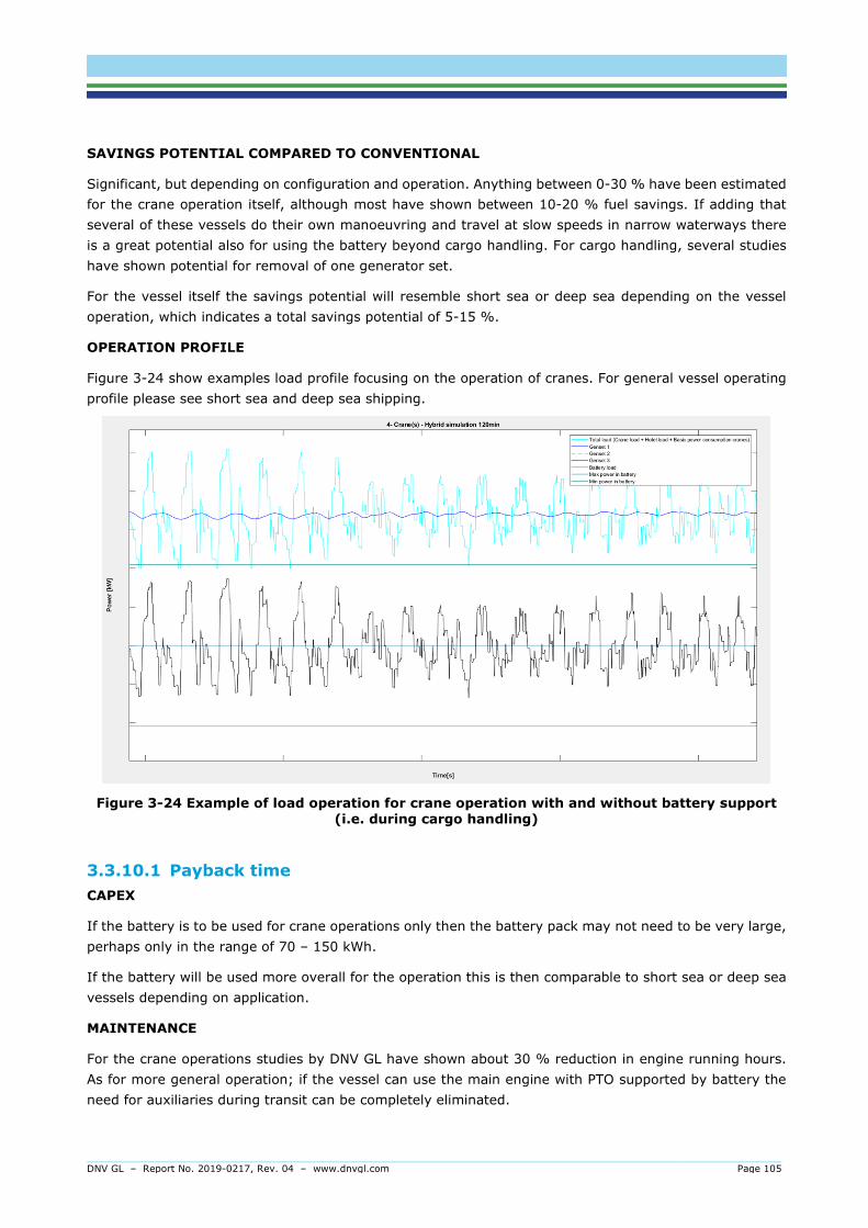
DNV GL – Report No. 2019-0217, Rev. 04 – www.dnvgl.com Page 105
SAVINGS POTENTIAL COMPARED TO CONVENTIONAL
Significant, but depending on configuration and operation. Anything between 0-30 % have been estimated for the crane operation itself, although most have shown between 10-20 % fuel savings. If adding that several of these vessels do their own manoeuvring and travel at slow speeds in narrow waterways there is a great potential also for using the battery beyond cargo handling. For cargo handling, several studies have shown potential for removal of one generator set.
For the vessel itself the savings potential will resemble short sea or deep sea depending on the vessel operation, which indicates a total savings potential of 5-15 %.
OPERATION PROFILE
Figure 3-24 show examples load profile focusing on the operation of cranes. For general vessel operating profile please see short sea and deep sea shipping.
Figure 3-24 Example of load operation for crane operation with and without battery support (i.e. during cargo handling)
3.3.10.1 Payback time CAPEX
If the battery is to be used for crane operations only then the battery pack may not need to be very large, perhaps only in the range of 70 – 150 kWh.
If the battery will be used more overall for the operation this is then comparable to short sea or deep sea vessels depending on application.
MAINTENANCE
For the crane operations studies by DNV GL have shown about 30 % reduction in engine running hours. As for more general operation; if the vessel can use the main engine with PTO supported by battery the need for auxiliaries during transit can be completely eliminated.

DNV GL – Report No. 2019-0217, Rev. 04 – www.dnvgl.com Page 106
FUEL
For use with cranes: 10 – 20 % fuel saving has been shown in various feasibility studies, although depending on configuration the number varies between 0-30 %.
For the ME+PTO+battery case the fuel saving potential is not well investigated at this time, although in most cases it can be assumed that the auxiliaries are not dimensioned for the hotel load, but for cargo handling. This could lead to low load scenarios on the auxiliaries which could be significantly improved.
PAYBACK
Crane hybridisation: 0-3 years. Some cases even result in a cheaper overall investment due to removal of genset(s). The full vessel hybrid will be more similar to short sea shipping or deep sea depending on application.
3.3.11 Tugboats HOW BATTERIES COULD BE USED
Tugboats represent a segment that is operating close to the cities4 and as such they can be subject to more scrutiny than other segments.
In port tugs can use batteries in on-off mode (low hotel loads). During transit batteries can act as peak shaver, and even operate all battery powered for short transits. Peaks are also possible to handle with batteries. Tug operation is usually short bursts of power. The profile of the tugs varies greatly depending on how busy the port is, and if it is mainly doing coastal/port work or offshore towing.
4 all electric tugs are under construction in Turkey, and 12 hybrids already in operation, including LNG hybrids in Australia.
FEASIBILITY
Table 3.13 give a brief overview of the feasibility of tugboats for typical application types.
Table 3.13 Feasibility of tug boats for typical application types
Application Feasibility description
All battery Feasible for relatively set operations. A series of four vessels currently under construction in Turkey
Hybrid Feasible and implemented on a number of tugs already, ranging from USA to Australia to Europe
Spinning Reserve Feasible and relevant
Peak shaving Feasible and relevant
Fuel cell Not commercially tested, however, a potentially feasible solution if combined with batteries
4 Offshore tugs are not considered here.

DNV GL – Report No. 2019-0217, Rev. 04 – www.dnvgl.com Page 107
BATTERY REQUIREMENTS
High power, low cost, high energy density (energy/volume and weight), safety
Relevant chemistries are: NCM, LFP, LTO
SAVINGS POTENTIAL COMPARED TO CONVENTIONAL
In addition to battery hybridisation, shore power should be implemented for tugs since they are operating in port, and there are usually several tugs operating in the same port, making the shore power investment a good idea.
Possible to reduce number of generators in some cases. In general, possible to reduce engine running hours, and improve efficiency on running engines.
Fuel savings have been estimated to 5 – 15 %, although in the literature there are examples of even greater savings in theoretical studies. For all electric tugs the fuel saving is naturally 100 %, although from a cost perspective this is not necessarily the case.
OPERATION PROFILE
Figure 3-25 shows an example load profile for a tug measured over one week. As can be observed the profile shows several bursts of power during tug operations, and several long periods with only a minimum hotel load.
Figure 3-25 Example of load profile for a tug boat
3.3.11.1 Payback time CAPEX
This depends on the hybrid or fully electric. Current solutions range from 100 kWh to 1,5 MWh.

DNV GL – Report No. 2019-0217, Rev. 04 – www.dnvgl.com Page 108
MAINTENANCE
Similar as for offshore supply vessels. If shore power is also incorporated a lot of engine maintenance can be eliminated.
FUEL
Similar as for offshore vessels, around 10 % expected overall. If shore power is applied this will further reduce fuel consumption.
PAYBACK
Varying depending on hybrid or fully electric configuration. Studies have shown varying results between 2 – 8 years.
3.3.12 Yachts HOW BATTERIES COULD BE USED
Yachts represent a very peculiar segment. They are mostly one of a kind in terms of design, they are relatively small and they are very large. They are also privately owned private boats, owned by high net worth individuals, which makes them different from most other segments. Yachts as such are not meant to generate an income, although most yachts are chartered out to those that can afford the price tag also.
While on OSVs the whole point of using batteries is from a safety and energy efficiency standpoint; on a yacht it is more from a comfort and energy efficiency standpoint.
Batteries can be used during port stays or at anchor (silent nights, no smoke) and as black out prevention by acting as a grid stabiliser. This in itself can save fuel and engine running hours by allowing for less online power from engines. Silent arrival and departure are also possible.
A challenge with yachts when talking about energy is that the yacht is often either lying still or moving very fast. When lying still the people on board want all the gadgets up and running, while in transit they most often want to get from a to b as fast as possible. On top of this is having the most special yacht with the highest performance and the newest technology. Yachts have already incorporated batteries on several projects.
FEASIBILITY
Table 3.14 gives a brief overview of the feasibility of yachts for typical application types.
Table 3.14 Feasibility of yachts for typical application types
Application Feasibility description
All battery Not feasible with current technology
Hybrid Feasible and already implemented on several mega yachts
Spinning Reserve Feasible, however, probably not the most relevant use for yachts
Peak shaving Feasible, and a desired feature for yachts. Batteries enable more stable grids which is preventing blackouts. Yachts are all about comfort and losing power is a significant factor
Fuel cell Feasible, however, not commercially proven

DNV GL – Report No. 2019-0217, Rev. 04 – www.dnvgl.com Page 109
BATTERY REQUIREMENTS
High power, high energy, high energy density.
Relevant chemistries are: NCM, LFP, LTO
SAVINGS POTENTIAL COMPARED TO CONVENTIONAL
The savings potential for yachts is difficult to estimate. Batteries will mainly be used during port stays and manoeuvring. It is estimated that yachts can save in the region of 5-10 % fuel and maintenance. In an on-off scenario the battery could provide power for several hours before switching back to engines. It should also be noted that while in port many yacht have shore power. The battery can then also enable optimal loads for the shore system, again avoiding black outs.
OPERATION PROFILE
Very varied and not possible to give a generic profile, although some comments can be made. In essence there are two types of yacht owners; the ones that actually use the vessel for sailing, and the ones who are on the vessel in some location. Yachts are also very often chartered out to various high net worth individuals.
Customers in general want to get from a to b fast, not really worrying too much about fuel efficiency while the crew can transit between locations at eco speed. Other characteristics are long port stays, virtual anchor, weather-vaning (“DP”), grid stability and high requirements to comfort. In addition, comes the “wow” factor that is often important in this segment.
For the ports stays the vessels are often connected to shore power. Batteries can help stabilise this avoiding black outs. In addition, yachts often have “capsuled” generator(s) for very silent operation. This genset is thus used for a majority of the time, and can also be more challenging for maintenance.
3.3.12.1 Payback time CAPEX
The all electric yacht will remain a dream for some time, however, it will not be long before yachts will be looking more towards fuel cells and batteries than traditional combustion. This all depends on availability of fuel.
The current yachts with batteries have batteries in the range of 100 kWh to multi MWh.
MAINTENANCE
Using the battery in combination with shore power or “silent night” modes could reduce the running hours on gensets significantly.
FUEL
While savings can be made, the main savings in terms of fuel are most likely a result from using shore power and potentially by more efficient use of gensets in pure hotel mode.
PAYBACK
Depending on the use it should be possible to have a reasonable payback time for yachts with a hybrid battery configuration. This has not been calculated in this study. Yachts represent a segment that perhaps is not the most worried about payback times.

DNV GL – Report No. 2019-0217, Rev. 04 – www.dnvgl.com Page 110
3.3.13 High speed ferries HOW BATTERIES COULD BE USED
All electric possible for short distances, however, high speed vessels use a lot of energy, and hybrids will be the most likely option for most cases. BB Green is one example of a high speed passenger vessel running on batteries only.
There are already high speed passenger vessels with batteries and hydrogen fuel cells in the planning stages.
The main challenge with batteries for high speed vessels are twofold: on one hand it is getting enough power, energy and cycle life, on the other it is getting the weight as low as possible.
FEASIBILITY
Table 3.15 gives a brief overview of the feasibility of high speed ferries for typical application types.
Table 3.15 Feasibility of high speed ferries for typical application types
Application Feasibility description
All battery Feasible for short routes (BB Green)
Hybrid Feasible. Solutions with batteries and fuel cells are being investigated.
Spinning Reserve Feasible.
Peak shaving Feasible. Batteries will typically support some combustion engine/fuel cell configuration.
Fuel cell Likely candidate to support zero emission routes. Currently being investigated for routes in Norway.
BATTERY REQUIREMENTS
High power, low weight, high energy, cycle life.
Applicable technologies: NCM and LFP are applicable for hybrid configurations. LTO is applicable for battery only and hybrid.
SAVINGS POTENTIAL COMPARED TO CONVENTIONAL
A study by Selfa showed that a battery hybridisation (plug in hybrid) could save 85 % fuel. The BB Green saves 100 % fuel as it is all battery powered. The charging must be considered for both cost and environment.
For longer distances a hybrid solution is required.
OPERATION PROFILE
Figure 3-26 shows an example profile from a typical high speed passenger vessel, operating on a relatively short route with a transit time of about 20 minutes.

DNV GL – Report No. 2019-0217, Rev. 04 – www.dnvgl.com Page 111
Figure 3-26 Example of profile for a typical high speed passenger vessel
3.3.13.1 Payback time CAPEX
Potentially high investment due to large energy requirement.
MAINTENANCE
Potentially eliminated, or close to since batteries require very little maintenance.
FUEL
Potential for reduction up to 100 %, although the electricity must be taken into account.
PAYBACK
From an investment and payback time point of view it is observed that there may be a significant increase in CAPEX. While the savings can be great from an operational standpoint the payback time should be expected to be around 3-6 years. This should be investigated per project.
3.3.14 Wind farm support vessels HOW BATTERIES COULD BE USED
Wind farm support vessels is a segment with a few sub categories.
On one hand there are Service Operations Vessels (SOV), these vessels have many of the same operational characteristics as OSVs. And can for all practical purposes be described also as small and quite capable OSVs. There are also some more unusual consumers such as walk to work personnel gangways and davit systems for deploying small crafts. Often these are also DP-2 or DP-3 vessels (again similar capabilities to OSVs).
At the other end of the spectrum there are the Wind Farm Service Vessels (WFSVs) and Crew Transfer Vessels (CTVs). These are typically 24m or smaller aluminium catamarans. These will transit out to the windfarms from a shore logistics base each day (1-2 hrs), spend the day mixed between darting around the field and idling/drifting depending on where they need to deploy technicians to. WFSVs may also work together with SOVs or floatels5 if the personnel are being accommodated offshore (particularly during construction phases), this may increase their utilization when they are in the wind farm.
5 Floating Hotels

DNV GL – Report No. 2019-0217, Rev. 04 – www.dnvgl.com Page 112
FEASIBILITY
Table 3.16 gives a brief overview of the feasibility of wind farm support vessels for typical application types.
Table 3.16 Feasibility of wind farm support vessel for typical application type
Application Feasibility description
All battery Depending on the field it can be feasible, although hybrid is a more likely solution
Hybrid Feasible
Spinning Reserve Feasible
Peak shaving Feasible. Batteries will typically support some combustion engine/fuel cell configuration
Fuel cell Feasible. Not commercially proven, however, as windfarms are in essence zero emission it is a likely candidate to require zero emission support
BATTERY REQUIREMENTS
• SOVs: similar to OSVs
• WFSV and CTV: lightweight, high energy, cycle life, high power, low cost
SAVINGS POTENTIAL COMPARED TO CONVENTIONAL
SOVs will have similar profiles as OSVs, with potentially large savings while on DP.
The smaller crafts could potentially be all electric for some fields.
OPERATION PROFILE
The operational profile for this vessel group will very similar to OSVs on hand, while on the other the smaller crew transfer vessels have a profile more similar to high speed ferries in the sense that they are either moving fast or dead slow.
3.3.14.1 Payback time CAPEX
For the SOVs this will most likely be similar to OSVs, with battery sizes ranging from 300 – 900 kWh. For fast crew transport vessels the CAPEX is more unclear.
MAINTENANCE
Similar as for OSVs can be expected.
FUEL
Similar as for OSVs can be expected.
PAYBACK
Similar as for OSVs can be expected.

DNV GL – Report No. 2019-0217, Rev. 04 – www.dnvgl.com Page 113
4 ENVIRONMENTAL AND SOCIAL ASPECTS Questions are often raised about how environmentally friendly battery-powered solutions are in a life-cycle perspective. Some of the environmental and social aspects of the utilisation of maritime batteries are addressed in this section.
4.1 Life-cycle assessments Many life cycle assessments (LCA) have been performed to investigate the environmental benefits and potential drawbacks of batteries, mainly for the car industry. An LCA quantifies the environmental impact of a process given all aspects of the value chain, from production to end-of-life processes, such as recycling and land-filling. Figure 4-1 shows an example of a potential life cycle circular process of a maritime battery. The different phases will be discussed below.
Figure 4-1 Illustration of a potential life cycle circular process of a maritime battery.
4.1.1 Raw material extraction /Materials processing The batteries consist of different materials (for more information on different battery technologies, see Section 1). The extraction of the raw materials will be the first step of a battery life. It involves activities related to the acquisition of natural resources, including mining non-renewable materials, harvesting biomass and transporting raw materials to processing facilities. The materials processing prepares the natural resources by reaction, separation, purification and alteration for the manufacturing and production phase (EPA, 2013).
Looking from a life cycle perspective and the materials used in the batteries, some battery types have a lower impact. Lead-acid batteries contain poisonous lead, while nickel cadmium batteries and NiMh batteries contain rare earth materials. Lithium-ion batteries, on the other hand, do not contain poisonous heavy materials and very little rare earth materials. Their main environmental footprint comes from the energy used in the production process.

DNV GL – Report No. 2019-0217, Rev. 04 – www.dnvgl.com Page 114
The mining and refining part of the life cycle has a relatively low contribution to environmental impacts, and there are relatively small differences among the different chemistries (Romare & Dahllöf, 2017). However, when making the electrodes and electrolytes the choice of material is very important as the environmental impact is dependent on the material used in construction. The mining of some of the electrode materials increases the environmental footprint, due to the toxic substances leak from mine tailing (European Commission, 2018). Section 1 includes various battery chemistries, with some of them being investigated specifically because of the more plentiful or environmentally friendly cathode material(s). As an example; lithium sulphur batteries contain lithium and avoid nickel and cobalt. This results in an estimated 22% lower toxic impact compared to standard lithium-ion battery (NMC111), as it avoids the mining and production activities of nickel and cobalt. Even though, these batteries may have lower toxic impacts than the standard Li-ion batteries, the consideration of other environmental impacts may not be improved, and overall they may not be more environmentally friendly (European Commission, 2018).
Details regarding general supply and mining of some of the main components used in NMC (the volume leaders in maritime industry):
Cobalt gives li-ion batteries stability and energy density, yet also contributes to higher volume and cost. Thus, it is already a target for reduction as an element in lithium-ion batteries – as exemplified in the push towards lower Cobalt content NCM (Section 1.2.1.1). Furthermore, more than 60 % of the world’s cobalt is mined in the Democratic Republic of Congo, which has significant political and ethical downsides, leading to several ongoing initiatives for responsible mining of cobalt.
Nickel is an important and relatively expensive component in lithium-ion manufacturing. It is a valuable metal used widely as a component of stainless steel. Thus, increasing demand from these uses can cause price spikes, while an oversupply will cause prices to drop. Overall, the market is well-developed.
Lithium supplies are significant but only one-third is considered economically accessible, primarily from salty, briny lakes, and the evaporation process can be lengthy. Still, based on total availability and underutilized sources in Chile, China and Australia, lithium supplies appear reliable for the long term.
There is likely to be increased pressure on material resources as the demand for batteries increases. The choice of material can present issues such as availability of resources, toxicity, safety, production and recycling or disposal impacts. This will nominally correspond to an increase in price of raw materials, which is ultimately likely to increase opportunity and feasibility of recycling and refurbishing or ‘second life’ use of batteries. Notably, increasing energy density of batteries relative to material contents will ultimately require less material and thus improve use of resources and reduce any toxic impacts. (European Commission, 2018).
4.1.2 Manufacturing / Production The various components need to be assembled, and the battery will be produced. The manufacturing has a significant impact on the environmental footprint on the batteries, as the production of lithium-ion batteries is very energy-intensive.

DNV GL – Report No. 2019-0217, Rev. 04 – www.dnvgl.com Page 115
4.1.3 Transportation/ Delivery Before the battery can be used, it will need to be transported and installed on board the ship. The transportation process requires energy, which must be taken into account when looking at a life cycle perspective. The impact of this phase depends on the distance the battery will have to travel before installation of the battery on board the vessel.
4.1.4 Product use/ Operation on ship When the battery is installed on board a ship, it is normally dimensioned based on the planned operation of the vessel. As described in Section 1, the c-rate, delta state of charge and number of cycles are factors that will affect the size of the battery, which is typically dimensioned to last for 10 years of operation on board the ship.
4.1.5 Second life / End-of-life / Recycling SECOND LIFE
After the battery has degraded to the point where it no longer fits the operational profile of the vessel, it will (in most cases) have capacity left and may be refurbished for reuse and get a second life. The industry is still too early in the process to see maritime batteries available for 2nd life applications. Batteries which would be potentially viable for second life will still have storage capacity and can be used as e.g. grid stabilizers (Maritime Battery Forum, 2016). Second life is often discussed for automotive batteries and has significant interest from major car manufacturers. However, these batteries are small and require integrating and controlling many thousands of them for a grid application (for example). In contrast, a maritime system is already likely on the MW-scale and thus fewer systems would need to be integrated. It is a significant challenge for 2nd life batteries to control the individual modules if different battery systems are combined because they will have been used differently and thus have different states of health.
Would-be adopters as well as manufacturers may be hesitant to the use of secondary material as the battery degradation and the current state of the battery may be challenging to assess.
END OF LIFE
In general, lithium-ion batteries are considered to be at its end of life when its usable energy capacity reaches 80 % of its initial value (Peters, Baumann, Zimmermann, Braun, & Weil, 2017). This is a definition that can be questioned. “80 %” is based on a number of factors, and mainly comes from the automotive industry. A battery degrades more or less linearly down to a certain capacity (often simplified as 80 % remaining capacity) after which the battery degrades faster. This does not mean that the battery is spent, however, it means that with the current use profile the battery is no longer suitable, or that with continued use the rate of loss of capacity may increase non-linearly. Thus, the battery has then reached “end of life” for that application. At some point the battery can no longer be re-used and is ready for recycling.
RECYCLING
All batteries may be recycled regardless of chemistry. In most countries, battery producers6 have to sign up to a battery recycling scheme. Facilities used for the recycling of lithium-ion batteries exists. The value
6 Producer is often defined as the entity that brings the battery in to the relevant country, which means that the system integrator may often
have this responsibility.

DNV GL – Report No. 2019-0217, Rev. 04 – www.dnvgl.com Page 116
of the recycled materials more or less pays for the cost of the recycling (DNV GL, 2015). It has been suggested that 72-97% by weight of a lithium-ion battery may be recyclable.
In addition, lithium-ion battery recycling has proven to be feasible, with several companies providing this service. The current focus is on aluminium and copper recovery, as this provides the greatest revenue stream, with the low price of mined lithium proving to be highly competitive – as well as challenges with regard to quality. The full potential of such processes is limited primarily by the current low inflow of recycled, used or decommissioned batteries – refurbishment is presently a more common end-of life service resulting in an even better environmental footprint.
There are different types of recycling processes such as hydrometallurgical process, high-temperature or pyrometallurgical process and direct recycling process. Figure 4.2 gives an overview of some of the steps in and recycling process of a battery. The low-temperature recycling technologies are especially beneficial, because of lower energy use, less material transformation, and more direct reuse/recycling of materials used in batteries.
Figure 4-2 Battery end of life treatment (Recycling)
4.2 Emission reduction potential of maritime batteries For the maritime case, the environmental benefit of batteries can be overwhelming positive in many cases. This section highlights the emission reduction potential of maritime batteries, as well as discuss some of its downsides.
PERSPECTIVE 1: TANK TO PROPELLER
The potential environmental benefit of an all-electric vessel is unquestionable when considering the tank to propeller part of the value chain. Electrification of a vessel may completely remove the emissions of CO2, NOx, particulate matter (PM), SOx and noise (noise depending on propulsion arrangement). This is correct for an all-electric vessel, compared to operating on MGO. For a hybrid vessel, the effect of the emissions reduction will depend on the level of hybridization.

DNV GL – Report No. 2019-0217, Rev. 04 – www.dnvgl.com Page 117
However, the environmental savings depend on the emissions created by generating electricity. In order to be emission free. battery-powered vessels are dependent on the electricity to be sourced from renewable energy. For instance, the environmental savings from all-electric vessels are huge if the charged electricity comes from the Norwegian electricity-mix, which is a close to 100% renewable electricity generation (Maritime Battery Forum, 2016), (Zackrisson, Orlenius, & Avellän, 2010), (Nordtveit, 2017).
As described in Section 3, for some of the segments it is neither technically nor economically possible to have all-electric operations. According to a possibility study carried out by Siemens and Bellona, 70 % of the Norwegian ferries are profitable with electrical operations (Bellona, Siemens, 2015). The potential CO2 reduction will be 300 000 tonnes, corresponding to 9 % of the annual national emissions from shipping and fisheries. Additionally, the annual fuel consumption will be reduced with about 100 000 tonnes, as well as the annual NOx emissions will be reduced with about 8 000 tonnes.
Combining batteries with combustion engines reduces local pollution and climate impact (Lindstad, Eskeland, & Rialland, Batteries in offshore support vessels - Pollution, climate impact and economics, 2016). The standard setup gives higher CO2 eq. emissions per kWh produced than the hybrid options. This difference in CO2 eq. emissions is larger in the Arctic (app. 40-45 % reduction in annual GWP20) than in the North Sea (app. 20 % in annual GWP20), due to the impact of the Black Carbon (BC).
PERSPECTIVE 2: LIFE CYCLE PERSPECTIVE
Several studies have investigated and compared the CO2-equivalent emissions on a life cycle perspective for conventional combustion system and battery system for the automotive industry. For maritime applications, very few life cycle assessments have been undertaken for on-board battery systems. In a study for the Norwegian NOX fund, the environmental payback period compared to a traditional drive configuration was calculated for a hybrid platform supply vessel (PSV) and an all-electric ferry (Maritime Battery Forum, 2016). In this section, the environmental payback time for the vessel segments in Section 3.2 are estimated. To limit the scope and the complexity of the calculations, the estimation is focusing on the CO2-equivalent emissions (global warming potential).
The environmental payback for the vessel segments has been estimated based on:
Annual fuel consumption; fleet data based on AIS from 2018 have been used as input for the annual fuel consumption for the various vessel segments, and the average has been applied. This means that both highs and lows are omitted; however, the results give an indication on the average for the segments.
Annual fuel savings; The potential fuel savings for the installation of a battery on board the vessels is based on the assumptions/estimation made in Section 3.2. The various vessel segments may have different potential fuel savings.
Battery capacity; The same potential battery capacity for the various vessel segments as in Section 5.2, are taken into account in these estimations. As there is a variety for several segments the numbers for a typical battery size has been used.
GWP per battery capacity (kWh); 285 kg CO2 equivalent per kWh is used for all segments and is based on the results from (Maritime Battery Forum, 2016). Even though the number may vary from segments to segments.
Some of the vessel segments are currently not feasible for all-battery propulsion solutions, and the environmental payback time are then estimated for a hybrid solution. It is assumed that the annual fuel saving for the all-electric solution will be 100%. For the all battery powered alternatives, a European electricity mix has been considered. According to (Maritime Battery Forum, 2016) a kWh of MGO

DNV GL – Report No. 2019-0217, Rev. 04 – www.dnvgl.com Page 118
corresponds to 0.33 CO2-eq per kWh and 0.004 kg NOx per kWh of MGO, including emissions from combustion and production. In comparison, the electricity mix for the EU has a GWP of 0.47 kg CO2-eq per kWh and 0.0008 kg NOx per kWh, meaning that the MGO has lower GWP emissions on unit energy basis than the EU electricity mix. The vessel must therefore be more energy efficient to beat the electricity mix as it is now.
The environmental payback time for the various segments have been calculated and listed in Table 4.1. The ferry and the PSV cases that were included in the study carried out for the Norwegian NOx fund are used for these segments.
Table 4.1 Estimated environmental payback time for various vessel segments in months.
For cruise vessels the environmental payback time is estimated to be more than a year, which is quite high compared to the other segments. Even though an environmental payback period of less than 2 years is not much, cruise is still a segment that is challenging with regards to battery installations. Shore power is not taken into account for these calculations, which would have increased the annual fuel savings for cruise. Emissions is then dependent on what electricity mix is being used. You may remove the local pollution, however, from a global warming perspective the project could be worse of.
Fish farm vessels represent a segment that will potentially have large savings if fitted with batteries and charging infrastructure. For the figures annual fuel savings of 20% have been considered, although various projects calculate savings in between 10 – 35%.
For short sea shipping all battery powered vessels have so far not been a reality but may soon become one. Yara Birkeland is one of the first examples of this. A combination of improved battery technology and smarter ways of operating the fleet may allow for all battery powered short sea shipping.
COMMENTS OF RESULTS/ UNCERTAINTIES
The majority of the reviewed studies do not provide own original inventory data, but rely on those of previous works, which can be seen as a weakness of the studies. This is also the case for this study as it is based on the results from (Maritime Battery Forum, 2016). Additionally, average values have been used as input for the estimation of the environmental payback time, which adds to the uncertainty. Still, the table shows numbers that are ballpark of what can be expected for the various segments.
The value for kg CO2-equivalent per kWh of a battery component used in the estimation of environmental payback time was 285 kg CO2 eq./kWh, which is based on (Maritime Battery Forum, 2016). Similar LCAs of lithium-ion batteries for cars indicate a GWP of 60 to 214 kg CO2-equivalent per kWh for energy storage (EPA, 2013), (Peters, Baumann, Zimmermann, Braun, & Weil, 2017) (Ellingsen, et al., 2013). As the
Environmental payback time All-electric Hybrid Ferry 2.5 Similar as for all electric, if plug-in Offshore supply vessel (OSV) Na 1.5 Cruise Na +12.0 Offshore drilling vessel Na 1.4 Fishing vessel Na 8.0 Fish farm vessel 3.3 6.7 Shuttle tanker Na 1.5 Short Sea 2.5 8.0 Bulk vessel Na 0.2 Tug 2.5 8.6 Yacht Na 8.5 High speed vessel Similar to ferry Wind farm vessel Na 1.5

DNV GL – Report No. 2019-0217, Rev. 04 – www.dnvgl.com Page 119
packaging and control systems are larger for a vessel compared to a car, the energy storage for a ship should have a higher GWP than that of a car.
Regardless of the study performed, the results rely highly on the electricity mix used for the calculations and influences the total impact of the battery. For instance, for the fully electric ferry, the environmental payback period for GWP is 1.4, when using the Norwegian electricity mix. For the EU electricity mix, the GWP payback time increased to 2.5 months, and for a global electricity mix to almost 12 months.
The production of lithium-ion batteries is energy-intensive, and the carbon-intensity of the energy used to manufacture the batteries impacts their environmental footprint. The results in (Maritime Battery Forum, 2016) showed that, for both vessels, most of the emissions come from producing the energy storage part of the system (typically the battery cells and packaging). According to various sources, battery manufacturing/production contribute to a significant share of the environmental impact over lifetime, which depends on the charge-discharge cycles provided by the battery, depth of discharge, charging rate degradation in the cell over time and cycles. All important for the overall environmental performance.
4.3 EEDI and batteries The Energy Efficiency Design Index (EEDI) aims to promote the use of more energy efficient (less polluting) equipment and engines. It is presently the primary manner for evaluating or representing the ‘green’ credentials of a vessel and thus is an important technical measure, also because it establishes requirements as far as minimum energy efficiency level per capacity mile for different ship type and size segments. By improving the energy efficiency of the vessel, both fuel consumption and EEDI can be reduced.
The EEDI for a vessel is calculated by a mathematical formula which takes into account the theoretical energy consumption of the vessel based on the engines installed, measures to improve efficiency and the size and capacity of the vessel. The EEDI formula is shown in Figure 4.3. The top line of the formula can be divided into four key parts; CO2 emissions related to propulsion power, CO2 emissions related to auxiliary power, CO2 emission reduction through energy efficiency technology to reduce auxiliary power; CO2 emission reduction through energy efficiency technology to reduce propulsion power. The bottom line of the formula represents the transport work capacity of the vessel.
Figure 4-3 EEDI formula
So far, the market players have expressed that the current provisions in the EEDI are not adequate for the energy savings batteries can offer. This is also something that is emphasized in the 2014 Guidelines on the Method of Calculation of the Attained Energy Efficiency Design Index (EEDI) for New Ships. This is also illustrated in the three cases presented below. The main reason is that the actual operational profile of the vessel is not reflected in the EEDI calculation. It is unclear how the operational savings by electric solutions can be numerically manifested in the design context since the EEDI-formulation is not geared towards crediting such solutions.

DNV GL – Report No. 2019-0217, Rev. 04 – www.dnvgl.com Page 120
THREE EXAMPLE CASES
To better illustrate the challenges with regards to batteries and the current EEDI formula, three high-level cases are presented. They are taken from another DNV GL study for the Norwegian Coastal Administration. The three cases include a general cargo vessel, a RoPax ferry and a shuttle tanker. For each vessel, the EEDI has been calculated for a conventional propulsion system and a non-conventional propulsion system. The main characteristics for the three case vessels are listed in Table 4.2. The result of the EEDI calculation for the three cases are listed in Table 4.3, in the bottom of the page.
Table 4.2 The main characteristics of the three example cases used to illustrate the difference in EEDI between a conventional propulsion system compared to a non-conventional propulsion system.
Case Vessel type Conventional propulsion
system Non-conventional propulsion
system7
1 General cargo vessel Capacity: 35 000 dwt
Vref: 14 kn
- 1 x constant speed 4-stroke engine
- MCRME: 8 500 kW, PME: 75 %MCR
- 1 x CPP
- 4 x generator sets
- MPPMotor: 8 141 kW PME: 83 % MPP
- 2 x PODs
2 RoPax ferry Capacity: 50 000 dwt
Vref: 17 kn
- 2 x constant speed 4-stroke engine
- MCRME: 20 000 kW PME: 75 % MCR
- 1 x CPP
- 4 x generator sets
- MPPMotor: 28 700 kW8 PME: 83 % MPP
- 4 x PODs (2 in each end of the ferry)
- Double ended design
- Vref increased to 19.5 as more propulsion power is installed due to the double ended design
3 Shuttle tanker Capacity: 150 000 dwt
Vref: 15 kn
- 1 x 2-stroke engine
- MCRME: 17 000 kW
- 1 x CPP
- 4 x diesel generators
- MPPMotor: 21 100 kW9
- 2 x PODs
Table 4.3 EEDI rating for the three example cases for a conventional configuration scenario and a non-conventional configuration scenario.
Case Vessel type EEDI - Conventional configuration
EEDI - Non-conventional propulsion system
1 General cargo vessel 8.25 gCO2/tnm 9.51 gCO2/tnm 2 RoPax ferry 7.27 gCO2/tnm 7.95 gCO2/tnm 3 Shuttle tanker 3.53 gCO2/tnm 4.11 gCO2/tnm
7 For the non-conventional configuration, the MPPMotor is in this case selected with reversed engineering based on the EEDI document
“EEDI Frameworks for ships not covered by the current EEDI”. PME may be considered equivalent to the estimation valid for diesel-
electric LNG tankers. In this case the following formula applies PME(i) = 0.83*(MPPMotor(i)/η(i)). 8 150 % of the conventional configuration for redundancy purpose. 9 133% of the conventional configuration for redundancy purpose.

DNV GL – Report No. 2019-0217, Rev. 04 – www.dnvgl.com Page 121
The results from the cases presented above show an increase of EEDI of about 10-15 % for the non-conventional case systems. The two main differences between the two configurations are the propulsion efficiency (~6 %) and the transmission losses (~9 %), which summarizes to about 15 %. As the results in Tab shows, this corresponds with the result of the EEDI calculations for the general cargo vessel and the shuttle tanker. However, this is not the case for the RoPax vessel. This is explained by the excessive machinery of the double ended design leads to an increase in Vref with a different correction factor for speed as result. The two different concepts will achieve EEDI-rating that is less than the estimated difference in propulsion and transmission efficiency. If the non-conventional configuration is instead fitted with 200% propulsion power, the EEDI-index will be 6 % higher than the conventional configuration.
The operational profile of the vessel will in most cases be utilized differently for different propulsion configurations. For speed lower than Vref (e.g. manoeuvring) it is likely that the non-conventional configuration can operate with a lower CO2 footprint than the conventional configuration, as one or more main generators can be switched off to maintain optimum engine load. At the same time the propulsion efficiency is reduced for the conventional configuration when operating with reduced pitch, this gives additional benefit for the non-conventional configuration with PODs in such operations. For instance, for the RoPax ferry, the two turning operation, one in each port of a return trip, will be excluded for the double ended design with two PODs, reducing e.g. fuel consumption and time. The time saved from the turning operations can be used to keep a reduced transit speed with maintained time table. For a shuttle tanker, often operating on DP, and the non-conventional configuration with PODs will have an increased possibility of operating more energy efficiently with variable rpm according to required amount of thrust. The main propeller for a conventional configuration will normally be kept close to zero pitch at elevated rpm for rapid thrust response. Operation at zero pitch might consume up to, or more, than 20% of the power consumed at free running ahead.
Looking from an environmental-friendly perspective, the non-conventional configuration allows for a relatively easy implementation of batteries, fuel cells or other means of innovative power storage or generation. In such cases, one or more of the generator sets may be replaced by other technologies that can be connected to the existing grid. Similar retrofit solutions will typically be more challenging and cost more to implement for the vessels with a conventional configuration.
The calculations performed had a given reference speed (Vref) for each case vessel, which corresponds to transmission loss and reduced propulsion power. Such binary operational profile might be well suitable for deep-sea shipping where cargo handling and transit at service speed roughly summarizes the vessel operational profile. However, it is challenging to find a method that sufficiently considers the benefits of non-conventional propulsion system with regards to reduced emissions in the operational profiles that is more complex including significant time in manoeuvring, slow speed, DP-operations and other operations that is deviating from service speed and stand-still. For that reason, the non-conventional propulsion solution may get an EEDI penalty, which may slow down the innovation and uptake of new technologies and solutions. Solutions and technologies that in total results in lower emissions.

DNV GL – Report No. 2019-0217, Rev. 04 – www.dnvgl.com Page 122
5 COST OF MARITIME BATTERIES In this section, various costs related to maritime batteries are investigated. This includes the investment cost (CAPEX), the operational costs (OPEX), in addition to prices.
Batteries have a wide price range depending on the application and chemistry. While (per early 2019) NCM and LFP typically are in the range of 500 – 1000 USD/kWh, LTO is typically double of this. In addition comes power electronics and related efforts towards engineering and installation. A common misunderstanding on battery costs is that people read the news about electric cars and the battery cost dropping to 100-200 USD/kWh. It is important to understand that then they are usually talking about the battery cell, or maybe a module, for a mass-produced system for cars. Ships require more custom-made systems with higher requirements for the battery, particularly with regard to safety. The “marinization” of the system means that maritime battery systems become significantly more expensive than car batteries.
For the sake of providing some guiding numbers in the following sections a battery cost of 1500 USD/kWh (per early 2019) is applied. This is for the installed battery, including power electronics that have been estimated roughly to be 150 USD/kW.
5.1 CAPEX The cost of system integration for a battery system are often significant and should be taken into account at an early stage of adoption. Taken the purchase price of the storage system, including power electronics, the total battery cost includes; purchase changes (PMS/IAS/DP), installation at yard (including electrical), FMEA, modifications of switchboard, commissioning and testing. The cost of the full battery system equals the collateral aspects combined. The lifetime of batteries is highly dependent on the duty cycle for which they are used, relative to the size of the battery.
For instance, a smaller battery will have reduced CAPEX but for a given application, will not last as long as a larger battery. Thus, sizing is a key aspect of battery system procurement. DNV GL has performed testing and modelling using a verification tool called Battery XT to assess these complex interrelated aspects. The life cycle additionally depends on battery chemistry – there are many different types of lithium-ion batteries – and also varies significantly based on manufacturer or vendor. Systems are most typically engineered and warrantied for ten years of operational life.
Maritime requirements also impact the cost of batteries intended for maritime usage. The main cost drivers compared to batteries intended for customer electronics and electric vehicles are related to enhanced safety and performance requirements, more stringent life time requirements and increased system complexity. Installations for ships are commonly customized (when compared to automotive applications) and produced in lower volumes.
Prices of lithium-based cells and systems have significantly been reduced over the last years – these trends in price reduction continue to surpass market forecasts and are expected to continue in the years to come.
5.2 OPEX Apart from efficiency, the OPEX costs are driven by electricity prices, which vary significantly from region to region. The electricity prices in Norway are typically around 0.12 USD/kWh, while the prices of electricity in EU range from 0.09 to 0.30 USD/kWh. Compared to marine diesel, assuming 11,800 kWh/t, and an average of 600 USD/t, the cost is 0.05 USD/kWh. However, the efficiency of using this energy in a battery-driven ship is significantly higher than that of a conventionally propelled ship, causing lower energy consumption and cost. As a result, the OPEX of an electric ship can be lower than its conventionally-powered equivalent. The battery system is about twice as efficient as a diesel generator. The efficiency of

DNV GL – Report No. 2019-0217, Rev. 04 – www.dnvgl.com Page 123
an electrical propulsion system will be approximately 76 to 85 per cent of the electrical energy provided from shore, whereas a typical diesel generator set will have a fuel efficiency of 40 to 45 per cent.
The efficiency of battery systems ranges from 85 to 95 per cent (round trip), while power electronics often have a 95 per cent efficiency. Power taken from the shore will likely see losses of 15 to 24 per cent by the time it reaches the propulsion motors, depending on the associated components and operation. By comparison, diesel propulsion systems rarely have an efficiency exceeding 50 per cent, especially in consideration of the redundancy requirements and low loading.

DNV GL – Report No. 2019-0217, Rev. 04 – www.dnvgl.com Page 124
PART B – STANDARDS/REGULATIONS/GUIDELINES FOR MARITIME BATTERY INSTALLATION
Battery installations in ships today operate within a complex regulatory context and development. On one hand, environmental regulations come into force at an increased pace driving the industry towards a turning point. On the other hand, development and application of safety rules for battery installations onboard ships are increasingly obtaining the necessary regulatory certainty for practical implementation of battery technology. Favouring compliance to current environmental regulations, in line with a more sustainable development in the shipping industry, power production by batteries is a technology that can eliminate NOx, Sox, particle (PM) emissions as well as CO2 emissions. This is a potentially huge change, especially when compared with emissions from diesel engines. Battery systems powered by low carbon fuels (e.g. natural gas and other low flashpoint fuels) or renewable electricity will have local, regional, and potentially global benefits as both emissions and noise are reduced. In the longer term, batteries obtaining their power from a growing number of renewable energy resources could lead to ships with near-zero carbon emissions.
Applicable standards and regulations for battery systems thus generally fall into the category of safety or environmental requirement. This part will identify and assess current regulations, codes & standards, including guidelines, related to the use of batteries in shipping. This part will also identify some of the regulatory gaps.

DNV GL – Report No. 2019-0217, Rev. 04 – www.dnvgl.com Page 125
6 STANDARDS, REGULATIONS AND GUIDELINES FOR BATTERY INSTALLATIONS IN SHIPPING
6.1 Introduction The present chapter provides an overview of current applicable standards, regulations and guidelines for the use of batteries in shipping. Regulatory information has been reviewed both on a national and international level. The current regulatory development and existing gaps towards safe and efficient use of batteries in maritime applications are reviewed. The overview provides a snapshot of the regulatory environment for battery installations onboard ships at the date of publication.
An important addition, of particular relevance to the Safety of maritime battery installations, in included in the this section of the report, with the extract of the main conclusions/recommendations of the MARITIME BATTERY SAFETY JOINT DEVELOPMENT PROJECT, led by DNV-GL which published in the end of 2019 the Technical Reference for Li-ion Battery Explosion Risk and Fire Suppression (Section 6.7)
6.2 International rules – IMO Shipping is an international industry, and international environmental, security and safety standards for shipping are developed by United Nation special agency, the International Maritime Organization (IMO). At the international level, IMO is the responsible body for drafting, discussing, approving, publishing and maintaining regulatory instruments that will be important for battery installations in ships.
Figure 6.1 provides an overview of the structure for the IMO organization. Further to the main structure presented, the IGF and IGC codes are included close to the Subcommittee on Carriage of Cargo and Containers – the one responsible for the work on the IGF Code. The IGF Code will, at international level, ultimately provide the necessary regulatory requirements for batteries in shipping.
In many cases, safety and technical requirements for a battery installation will be established by IMO 1455 - Guidelines for the approval of alternatives and equivalents as provided for in various IMO instruments. This is particularly the case in the absence of applicable or relevant Class rules or Flag state requirements.
Table 6.1 lists some key international rules.
Figure 6-1: Overview showing how IMO is organised

DNV GL – Report No. 2019-0217, Rev. 04 – www.dnvgl.com Page 126
Table 6.1 Key international rules (IMO) International rules (IMO)
Year of publication Short description
MARPOL Annex VI 2005 Prevention of Air Pollution from Ships - Sets limits on sulphur oxide and nitrogen oxide emissions
from ship exhausts and prohibits deliberate emissions of ozone depleting substances; designated emission control areas set more stringent standards for SOx, NOx and particulate matter.
- A chapter adopted in 2011 covers mandatory technical and operational energy efficiency measures aimed at reducing greenhouse gas emissions from ships (IMO, 2019).
SOLAS The International Convention for the Safety of Life at
Sea (SOLAS) - Defines as an international agreed minimum requirement
for the construction, equipment and operation of ships. Flag States must ensure that these minimum requirements are met.
- Chapter II-1 - Construction - Subdivision and stability, machinery and electrical installations, specifies amongst other things the requirements for generators for electrical power generation.
- The IMO subcommittee on Fire Protection (FP) has agreed to introduce new requirements for electrical equipment and wiring, ventilation and gas detection, and these requirements entered into force on 1st January 2016.
MSC.1Circ.1455 2013 Guidelines for the approval of alternatives and equivalents as provided for in various IMO instruments - intended for application when approving alternative
and/or equivalency designs in general and specifically according to the provisions given for alternative design and arrangements in applicable statutory IMO instruments.
- serve to outline the methodology for the analysis and approval process for which the approval of an alternative and/or equivalent design is sought.
IMDG Code International Maritime Dangerous Goods Code - Covers dangerous goods as packed cargo. - Does not include use of dangerous goods in the ship’s
own cargo tanks (as could be the interpretation for batteries used as “fuel” is not included.
Maritime battery applications must satisfy (a) requirements for on-board energy generation systems and (b) fuel-specific requirements regarding the arrangement and design of the fuel handling components, the piping, materials and the storage. In current regulations, these aspects are handled separately.
The use of batteries in ships does not yet appear to be on the agenda in IMO or its sub-committees. There is, however, some chance this will change as IMO will start to work with GHG measures as part of the follow up on the new GHG emission reduction targets. So far, it appears as most of the development work is done by the individual Flag States.
During the 72nd MEPC meeting, the “Initial IMO Strategy on reduction of GHG emissions from ships” was adopted (resolution MEPC.304(72)). The strategy sets out a vision and goals for IMO’s efforts to reduce

DNV GL – Report No. 2019-0217, Rev. 04 – www.dnvgl.com Page 127
GHG emissions and states that the ultimate goal is full decarbonization as soon as possible within this century. The specific goals are set as efficiency targets of at least 40% by 2030, pursuing efforts towards 70% by 2050, as well as reducing the total annual GHG emissions by at least 50% by 2050 compared to 2008 (IMO, 2018). These goals are to be pursued through measures that remain to be discussed at future meetings. Batteries are definitely part of the solution within in shipping, if these targets are to be met.
Additionally, the Directive on Sulphur Content in Marine Fuels (1999/32/EC) has been amended to include provisions of Annex VI of IMO’s Marine Pollution Convention, MARPOL 73/78. However, the European Commission has called for further action by the International Maritime Organization (IMO) to reduce emissions. An amended Annex VI was adopted in October 2008. MARPOL Annex VI lowers the maximum permissible sulphur content of marine fuels inside and outside of SECAs. These limits are EU law and are outlined in Directive 2012/33/EU.
FLAG STATE PRACTICES AND INTERPRETATION OF IMO FRAMEWORK
With the emergence of lithium-ion battery technology, Flag states have been required to act to put something in place as far as requirements. The approach taken and maturity of requirements for different flag states varies significantly from country to country – while the vast majority of nations do not have any stated requirements in place. Table 6.2 outlines guidelines for nations with publicly stated requirements.
Table 6.2 Some guidelines for nations with publicly stated requirements Flag state practices Year Short description Norwegian Maritime Authority
2016 Guidelines for chemical energy storage – maritime battery systems - The background for this Circular is to facilitate that ships
with installed battery systems maintain the same level of safety as ships with conventional operation.
- The Circular is issued pursuant to the Act of 16 February 2009 No. 9 relating to ship safety and security, in particular sections 6, 9, 11, 43 and 45, and the Regulations of 1 January 2005 No. 8 on the working environment, health and safety of persons working on board ship
- Applies to all Norwegian-registered vessels with installed battery systems based on Li-ion or similar technology.
- Danish Maritime Authority
Guidance on the Danish Maritime Authorities guidance for ship operations
US Coast Guard The USCG has preliminary unofficial requirements and is actively engaged in the development of an ASTM standard to state applicable battery safety requirements.
UK Maritime and Coastguard Agency
Marine Guidance Note MGN 550 (M+F) – Electrical Installations – Guidance for Safe Design, Installation and Operation of Lithium-ion Batteries - provides guidance as far as best practice with regard to
battery system design, storage & transportation, installation, operations & procedures, maintenance and disassembly/recycling.

DNV GL – Report No. 2019-0217, Rev. 04 – www.dnvgl.com Page 128
6.3 Codes and standards Many organizations exist which typically develop rules and standards to cover safety and test requirements of electric systems and stationary power systems, such as the International Electrotechnical Commission (IEC), Underwriter’s Laboratory (UL) and the International Organization for Standardization (ISO).
Table 6.4, Table 6.5 and list applicable standards for battery installations, specific maritime battery applications or battery technologies, and land to ship connections for use of shore power, respectively. Generally speaking, lithium-ion batteries represent a new and complex technology that is continuously evolving, and it is inherently a challenge for standardized testing practices to keep up to speed. However, there has been significant ongoing effort towards their development and as a result a useful and beneficial set of applicable standards does exist.
Within Table 6.4, there are several standards that have come to have a more prominent role in shaping the safety testing requirements used for battery installations in practice - providing test procedures and requirements for evaluating many key safety features and requirements of battery cells and systems. Of the highest relevance is UN 38.3 which applies to all battery systems which are to be transported. Further, IEC 62619 provides perhaps the most widely referenced safety test protocol for battery systems, particularly from an international perspective, and particularly with regard to the maritime industry. For instance, Class Rules will frequently reference this standard when identifying test setup or requirements. To give a better idea of scope of these standards a subset of tests outlined in IEC 62619 is provided in Table 6.3.
UL 1973 and UL 9540 have the greatest presence with regard to stationary energy storage system installations in North America, as opposed to IEC 62619. UL 1973 has been the most widely used for some time, though it should be noted that code officials in North America are indicating a desire for more large scale fire testing, as demonstrated by the development of UL9540A, a test method focused on the behaviour of systems with propagating thermal runaway. NFPA 855 and the revised 2021 International Fire Code are also nearing completion and are expected to have a large influence once complete, even prior to adoption.
Table 6.3 Example of required tests for battery cells and systems Cell Level Tests System Level Tests Test Number Description Test Number Description 7.2.1 External short-circuit 7.3.3 Propagation test 7.2.2 Impact test 8.2.2 Overcharge control of voltage 7.2.3 Drop Test 8.2.3 Overcharge control of current 7.2.4 Thermal abuse test 8.2.4 Overheating control 7.2.5 Overcharge test 7.2.6 Forced discharge test
Table 6.4 Relevant standards for battery installations
Standards Year of publication Short description
IEC 62619 2017 Secondary cells and batteries containing alkaline or other non-acid electrolytes
IEC 62620 (2014-12-01)
2014 Secondary cells and batteries containing alkaline or other non-acid electrolytes - Secondary lithium cells and batteries for use in industrial applications Edition: 1.0

DNV GL – Report No. 2019-0217, Rev. 04 – www.dnvgl.com Page 129
Standards Year of publication Short description
UN Manual of Tests and Criteria, UN DOT 38.3
2015 Transport of Dangerous Goods
IEC 62281 Edition: 2.0 (2014-02-01)
2014 Safety of primary and secondary lithium cells and batteries during transport
UL1642 Edition 5 (2012-03-13)
2012 Standard for Lithium Batteries,
UL1973
Standard for Batteries for Use in Light Electric Rail (LER) Applications and Stationary Applications
UL 9540 2016 Standard for Energy Storage Systems and Equipment
IEC 60529 Edition: 2.2 (2013-10-01)
2013 Degrees of protection provided by enclosures (IP Code)
IEC 61508 Edition: 1.0 (2010)
2010 Functional safety of electrical/electronic/ programmable electronic safety-related systems - Part 0: Functional safety - Relevant for BMS
IEC 60092-504 Edition: 3.0 (2001-03-22)
2001 Electrical installations in ships - Part 504: Special features - Control and instrumentation - Relevant for BMS
IEC 62061 Edition: 1.0 (2010-08-01)
2010 Guidance on the application of ISO 13849-1 and IEC 62061 in the design of safety-related control systems for machinery - Relevant for BMS
Table 6.5 Relevant standards for specific maritime battery applications or battery technologies.
Standards / Rule Year of publication Short description
EN 50110 Edition 2.N (2013-06-01)
2013 Operation of electrical installations -- Part 1: General requirements - Supporting documentation for batteries and electrical
testing
IEC 61508 Edition: 1.0 (2005-01-20)
2005 Functional safety of electrical/electronic/programmable electronic safety-related systems - Supporting documentation for batteries and electrical
testing
IEC 61511 Edition: 1.0 (2003-12-19)
2003 Functional safety - Safety instrumented systems for the process industry sector - Supporting documentation for batteries and electrical
testing
ISO 26262 Edition: 1 (2011-11-14)
2001 Road vehicles -- Functional safety - Supporting documentation for batteries and electrical
testing
IEEE 45-2002 2002 Recommended Practice for Electrical Installations on Shipboard

DNV GL – Report No. 2019-0217, Rev. 04 – www.dnvgl.com Page 130
Table 6.6 Relevant standards for land to ship connections of use of shore power. Standards / Rule
Year of publication Short description
IEC/ISO/IEEE 80005-1
2012 Utility connections in port - Part 1: High Voltage Shore Connection (HVSC) Systems - General requirements - Describes high voltage shore connection (HVSC) systems, on
board the ship and on shore, to supply the ship with electrical power from shore.
- The standard is applicable for design, installation and testing of HVSC systems and addresses HV shore distribution systems, shore-to-ship connection and interface equipment; transformers/reactors; semiconductor/rotating convertors; ship distribution systems; and control, monitoring, interlocking and power management systems.
- It does not apply to the electrical power supply during docking periods, e.g. dry docking and other out of service maintenance and repair.
IEC/IEEE 80005-2
2016 Utility connections in port - Part 2: High and low voltage shore connection systems - Data communication for monitoring and control - Describes the data interfaces of shore and ships, and it provides
step by step procedures for low and high voltage shore connection systems communication for non-emergency functions, where required.
- The standard specifies the interface descriptions, addresses and data type. The standard also specifies communication requirements on cruise ships.
- Application of this standard relates to annexes of IEC/ISO/IEEE 80005-1.
- This standard does not specify communication for emergency functions as described in IEC/ISO/IEEE 80005-1.
IEC PAS 80005-3
Utility connections in port: Low Voltage Shore Connection (LVSC) Systems - General requirements.
IEC/IEEE DIS 80005-3
Under dev. Nov 2018
Utility connections in port -- Part 3: Low Voltage Shore Connection (LVSC) Systems - General requirements
IEC 62613-1 High-voltage plugs, socket-outlets and ship couplers for high-voltage shore connection systems (HVSC-systems) - Part 1:General requirements
IEC 62613-2 High-voltage plugs, socket-outlets and ship couplers for high-voltage shore connection systems (HVSC-systems) - Part 2: Dimensional compatibility and interchangeability requirements for accessories to be used by various types of ship
IEC 60309-5 Plugs, socket-outlets and couplers for industrial purposes - Part 5: Dimensional compatibility and interchangeability requirements for plugs, socket-outlets, ship connectors and ship inlets for low-voltage shore connection systems (LVSC).

DNV GL – Report No. 2019-0217, Rev. 04 – www.dnvgl.com Page 131
6.4 Classification rules applicable for maritime battery installations
As is conveyed in this document, batteries are a very complex technology, and this is equally the case with regard to safety – a consideration that is given further detail in Section 9. Maritime possesses a significant benefit in addressing this challenge that stems from the existence and role of the Classification Society. Rather than necessarily relying on compliance to standards - with minimal consideration for key aspects of the specific system at hand, or provision for detail in reporting - the acceptability of systems is reviewed and enforced by a Classification society. This layer of evaluation ensures a high level of confidence in the safety and engineering design of such a new and rapidly changing technology, and it further enables it to be used by customers and vessel owners whom are not likely to have much experience or knowledge with regard to the technology. However, that confidence is only gained if the Classification society has invested to build the technical competence and knowledge to effectively evaluate the specific technology in question. This ultimately yields a very necessary understanding of the philosophy behind the rules, and an understanding of why the rules are in place when evaluating a given installation so that they may be interpreted and applied correctly. There are big variations between different ships, and similarly there is a wide range of battery systems and engineering approaches that must be evaluated thoughtfully and knowingly. The end result is that a Classification Society can be a hands on and knowledgeable partner in the battery integration process and this can greatly increase the level of confidence and safety.
Table 6.7 gives an overview of Classification Societies which have requirements in place which apply to (lithium-ion) battery installations on ships. Presently, some Classification Societies have put Rules in place in the main rules, while others have only issued guidelines or guidance notes, and many others have no requirements or regulations presently in place. To give a frame of reference, the following sub-section will provide a short summary of main points taken from the DNV GL rules.
Table 6.7 Overview of applicable Class requirements for battery installations and their status Short name
Association Title of document Type
ABS American Bureau of Shipping
Use of Lithium Batteries in the Marine and Offshore Industries
Guideline
BV Bureau Veritas Rules for Classification of Ships - Electric Hybrid
Rules - Pt F, Ch 11, Sec 22
DNV GL DNV GL
Rules for Classification of Ships - Battery Power
Rules - Pt 6, Ch 2, Sec 1
LR Lloyds Register Large Battery Installations Guideline
6.4.1 DNV GL class rules The DNV GL class rules cover the use of batteries as a part of the propulsion energy for vessels either by hybrid battery solutions or “pure” battery driven vessels. DNV GL published tentative rules for using lithium-ion batteries on-board vessels in 2012. These rules were updated and published in October 2015 under the common rule set of DNV GL. The latest edition of the DNV GL rules is from January 2018, with amendments from July 2018 (DNV GL, 2018). The requirements in the DNV GL Class Rules are function-based and applicable for all DNV GL classed vessels. The primary focus of the rules are the safety of the complete battery installation and the specific test requirements for such a system.
The Class rules for the Battery notations are found in Part 6, Chapter 2, Section 1 of the DNV GL Rules for Classification of Ships (DNV GL, 2018). The DNV GL Battery rules, with the class notations Battery (Power) and Battery (Safety) are applicable for hybrid installations combining batteries and fuel cells. The choice of notation depends on how the batteries are used in combination with the other power sources for the

DNV GL – Report No. 2019-0217, Rev. 04 – www.dnvgl.com Page 132
function in the ship. A breakdown of the purpose and applicability of the notations is provided below, while Table 6.8 gives a short description of some key requirements for Class approval of a battery system installation.
The two notations within DNV GL battery rules are:
Battery(safety)
• Battery (Safety) is mandatory for all DNV GL classed vessels where the installation is used as an additional source of power and has an aggregate capacity exceeding 20 kWh. Battery (Safety) can also be selected (not mandatory) for battery systems with less than 20 kWh capacity.
• The notation covers requirements for the safety of the battery installation covering vessel arrangement, environmental control including temperature and ventilation.
• To prevent thermal incidents in battery spaces, the rules gives requirement to fire integrity, detection and extinguish measures.
Battery(power)
• Battery (Power) is mandatory for vessels where the battery power is used as propulsion power during normal operation or when the battery is to be used as a redundant source of power for main and/or additional class notations.
• The notation Battery (power) is the class notation needed when the battery is used as a main source of power (propulsion power).
• The rules put requirements for redundancy and location. In addition, the time or range that the battery can supply energy shall be calculated when taking the planned operation/voyage into account.
Table 6.8. Selected components required for Class approval of a battery system installation. Rules Component Short description
Safety Description
The safety description is specific to the battery system, and provides key details and aspects of that system that can be used as input to other engineering or risk assessment exercises. This should include things like, cell size, expected offgas contents and quantities, BMS and module features, and propagation test results. Specific items to be included are listed in the Class rules.
Safety Assessment
The Safety Assessment is specific to the vessel on which the batteries are being installed. It thus utilizes input from the safety description and explains how key risks are handled in the installation. Specific items to be included are listed in the Class rules.
Standardized Tests
Rules that may be applicable in addition to the battery rules: - Dynamic positioning - Electrical installations - Control and monitoring systems
Propagation Test The propagation test that is required for DNV GL classed vessels is outlined in
the DNV GL rules. It is based on IEC 62619 with additional provisions and the requirement that it is performed, and passed, three times.

DNV GL – Report No. 2019-0217, Rev. 04 – www.dnvgl.com Page 133
6.5 Handbook for maritime and offshore battery systems The DNV GL Guideline for large maritime battery systems gives relevant input for hybrid configurations with batteries and it covers all the phases of a ship development project (DNV GL, 2014). Based on the experiences gained from the Guideline, DNV GL has updated it into a more comprehensive Battery Handbook for Maritime and Offshore Battery Systems (DNV GL, 2016).
The Battery Handbook provides inputs regarding development of battery and battery hybrid configurations. The main objective of the was to improve the systematics, tools and criteria for safe and efficient introduction of lithium-ion battery technology. Target applications include hybrid offshore vessels and all-electric ferries and passenger ships. However, the Handbook is also valid for mobile offshore units and most ship types where Lithium-ion based battery power in all-electric and in hybrid configurations are being considered. The battery information and recommendations in the Handbook are presented separately for the different phases of the ship building process. A main aim of this Handbook is to reduce barriers and contribute to faster and safer battery electrification in the maritime sector.
6.6 NMA circular SM3-2019 The Norwegian Maritime Authority (NMA) has alerted shipowners and operators to hazards associated with lithium-ion battery systems. This follows a fire and subsequent explosion in the battery room of the car and passenger ferry Ytterøyningen, which took place in Norway on 10 and 11 October 2019.
The NMA circular SM3-2019, issued on 14 October and clarified on 18 October 2019, recommends that shipowners using battery systems review their risk assessments related to unwanted incidents that may cause accumulation of explosive gases (Norwegian Maritime Authority, 2019). The Battery System manufacturer who supplied the ferry’s battery system has also issued additional recommendations10,11.
The following considerations provide input to be considered in risk assessments related to the mitigation of risk in case of fire adjacent to, or within, a lithium-ion battery system space (Norwegian Maritime Authority, 2019):
1. Conduct regular testing to confirm that the battery management system (BMS) is fully functional and that it remains connected to the ship’s alarm system, so that temperatures can be monitored during an emergency response.
2. Investigate alarms and take prompt action before clearing the alarm status, particularly where high cell or ambient temperatures develop.
3. Maintain fire insulation for the space in good condition.
4. Do not store combustible material or flammable compounds in the space.
5. Ensure that ventilation for the extraction of gases remains in a defined safe state during an emergency.
6. Ensure that fixed fire-fighting system release instructions are clear, correct and readily available.
7. Conduct crew training on the recommended instructions, with fire drills focused on actions necessary and on the timescales.
10 https://www.sdir.no/contentassets/3b7861436ee94274aa8fe30ea4df5aed/initial-response_nma_dnvgl.pdf?t=1588581605790 11 https://www.sdir.no/en/news/news-from-the-nma/supporting-preliminary-report-after-battery-incident/

DNV GL – Report No. 2019-0217, Rev. 04 – www.dnvgl.com Page 134
7 REGULATORY GAPS The objective of this chapter is to identify and describe existing gaps. In line with what has been done in previous studies, the gaps have been classified under three categories, described below. Notably, a significant volume of battery systems has been deployed in the maritime sector and, as reviewed in the preceding section, prescriptive rules have existed as a part of the common rules set since 2015. Thus, the vast majority of regulatory aspects and concerns for battery systems have been addressed in existing requirements. The items below thus are more so representing further improvements or refinements of these regulations based on continually improved technical understanding and quickly developing technology & system designs.
LEGAL GAP
Legal gaps are gaps for the use of batteries and the associated charging infrastructure that can severely limit or even block the use of batteries in shipping. These gaps are typically gaps in legislation and regulations.
HARMONIZATION GAP
Harmonization gaps are gaps in the EU-wide harmonization of methods, rules, guidelines, provisions and safety aspects for batteries. An example could be harmonization of conditions and procedures for safe charging.
KNOWLEDGE GAP
Specific knowledge gaps are points where more research is needed in the implementation and development of batteries for the maritime use and applications identified in this study. Recommendations formulated for these gaps are suggestions for improvement, as well as R&D and product development. Table 7.1 gives a high-level summary of the identified gaps in the gap analysis performed in this study.

DNV GL – Report No. 2019-0217, Rev. 04 – www.dnvgl.com Page 135
Table 7.1 Gap Analysis table – high level summary of identified gaps
High level Gap description
Recommendation/Assessment Gap Category12
BMS Capability Assessment
Battery Management Systems (BMS) are a vital component of the battery safety properties (ref Section 9). Yet are overlooked in many assessments because they are difficult to evaluate. These systems are studied in the most detail in DNV GL Type Approval. Wider deployment of more detailed practices for assessment such as HIL would have significant benefit at further reducing risk levels.
H
Battery cell quality assurance for safety
Battery cell quality and consistency is a key driver of safety yet is not currently evaluated under the existing regulatory framework. Implementation of more transparent documentation and processes could improve system safety characteristics.
K
Battery cell quality assurance for lifetime
Battery lifetime is difficult to assess. Although this is an engineering task and thus does not make sense to impose explicit rules, there are opportunities for further standardizing what is reported as far as lifetime for battery cells, even just as far as definitions.
K
Thermal runaway test procedures
As battery system safety properties improve, thermal runaway and propagation testing becomes more challenging. This leads to challenges with regard to writing test procedures and acceptance criteria; and harmonizing those requirements. Whether a cell has sufficiently entered ‘thermal runaway’ and that an acceptable propagation test has been performed is difficult to define. In addition, as safety properties improve to more directly address the core problem of internal manufacturing defect, this specific phenomenon may be more necessarily the focus of testing.
H, K
Allowances for batteries as backup / spinning reserve
The specific requirements stated for spinning reserve power (for example DP) would not allow for the use of batteries on retrofits, unless major updates at power consumers, producers, safety equipment and automation were installed. These specific requirements vary for different authorities.
L, H
Certification of different battery fire suppression systems
Each battery installation will require project/installation-specific capacity and functionality for the fire suppression systems. A view to the future will require adequately addressing at high-level regulatory framework the findings from the Technical Reference for Li-ion Battery Explosion Risk and Fire Suppression (DNV-GL, 2020). Actual volumes and release rates needs to be calculated and are dependent on the battery system, technology and specific battery room arrangement design.
L, H, K
12 L: Legal; H: Harmonization; K: Knowledge.

DNV GL – Report No. 2019-0217, Rev. 04 – www.dnvgl.com Page 136
PART C – BATTERY SAFETY AND SAFETY ASSESSMENT This part of the report provides a analysis of key aspects of battery safety, focusing on lithium-ion batteries. A HAZID workshop was undertaken to evaluate and summarize key aspects of safety as it pertains to an actual installation on board a vessel. This HAZID included participation from DNV GL multidisciplinary team, as well as Fiskestrand and Multi Maritime. This assessment was structured to analyse and provide guidance through the effects and characteristics of risk that arise from the multitude of different potential battery configurations, technical approaches, and technologies that exist in the market – including installation alongside a fuel cell.

DNV GL – Report No. 2019-0217, Rev. 04 – www.dnvgl.com Page 137
8 INTRODUCTION TO BATTERY SAFETY Any source of useful power, by definition, stores energy – gasoline, waterfall, a spinning flywheel, or a battery. With any such system, there is risk for that energy to be released in a manner other than how it was intended, often with potential safety consequences. Thus, a lithium-ion battery is no different, and the most important aspect is to be mindful of the issues it poses and ensure that they are addressed in system engineering.
This section provides a background of safety issues and requirements for consideration with regard to lithium-ion systems, followed by specific aspects and recommendations that should be taken into account with regard to installation on board a vessel.
8.1 Fundamental aspects of lithium-ion battery safety Safety concerns with regard to lithium-ion batteries come from two sources – one is the presence of flammable, unstable electrolyte, and the second is the presence of metal electrodes that can burn and often release oxygen. Ignition and likelihood of a safety event is largely linked to the flammable electrolyte, while the high temperature and difficult to extinguish nature of the fire is largely linked to the second aspect. Based on these components, there are two primary failure modes or effects that can result from lithium-ion battery abuse: cascading thermal runaway and the release of toxic and flammable gasses. This section will provide an account of main abuse mechanisms that pose risks with respect to lithium-ion battery safety, as well as description of these main effects and consequences that can results from such incidents (DNV GL, 2016).
8.1.1 Thermal runaway & propagation Thermal runaway is the exothermic reaction that occurs when a lithium-ion battery starts to burn. The thermal event often starts from an abuse mechanism that causes sufficient internal temperature rise to ignite the electrolyte within a given cell. This fire then poses significant risk of igniting the metallic electrodes that are contained within the battery cell, thus producing a high temperature metal (Class D) fire. Additionally, these metals may contain oxygen, which is thus released as it burns. Not all lithium-ion batteries contain oxygen within the electrodes but all lithium-ion batteries on the market today contain electrolyte that can ignite and cause this thermal runaway scenario.
A maritime battery system is typically made up of thousands of cells. Thus, the failure and total heat release of a single cell is a relatively minor threat. The greater threat comes from that thermal event producing sufficient heat that it propagates to other cells, causing them to go into thermal runaway. As this cascade through the battery, heat produced increases exponentially and the risk is developed of a fire in which the entire battery is involved. Thus, battery modules and systems must be engineered to protect against propagation based on the cell that is used, and these cascading protections are the key feature with regard to system design for safety.
8.1.2 Electrolyte off gas The electrolyte that is contained within a given cell consists of an organic solvent, typically variants of ethyl carbonates. This means that they are flammable, and additionally, this means the gasses that are produced during a failure scenario are also flammable and can present an explosion risk. These gasses also typically contain other species which are toxic – such as HCl and HF. These aspects of battery offgas thus require consideration with regard to ignition sources and ventilation within both the battery module and battery room.

DNV GL – Report No. 2019-0217, Rev. 04 – www.dnvgl.com Page 138
8.1.3 Battery technology considerations In addition to general safety aspects of lithium-ion batteries, there can also be significant differences between specific systems. These variations consist of the chemistry of the battery cells themselves, the design of the module (assembly of multiple battery cells) and the controls system internal to the battery, commonly called the Battery Management System (BMS).
BATTERY MANAGEMENT SYSTEM - BMS
The battery is only as strong as its weakest link (cell). All batteries within the system will degrade as slightly different rates. A quality BMS system will be best able to minimize those variations as it keeps batteries in balance. In addition, the BMS is responsible for calculating current limits, SOC, and State of Health (SOH). These are all complex functions that require years of experience and in-depth knowledge of the specific battery system. A high quality BMS system is a key component of a safe and fully effective battery system.
The BMS is also vital in preventing the converter overcharging the battery system. Such failures may cause more than one cell or module to fail simultaneously. Note that the most probable scenario for such failures is that any fire or off-gassing will start at the weakest cell or module, before spreading to the rest of the system.
BATTERY CELL AND CHEMISTRY CONSIDERATIONS
As stated previously, any lithium-ion battery will burn as it is an energy source. A battery system is built up of tens of thousands of cells. Thus, some of the key factors with regard to safety then are making sure in the case that one battery fails in some sort of thermal event that others around it do not do the same. A key aspect of this then is how much heat is produced by the cell. A larger cell will contain a larger amount of energy and thus produce more heat when it burns. Larger cells produce advantages with regard to energy content and density of a system but system design must be sure to take into account this larger size.
Chemistry is also a factor. The majority of lithium-ion batteries in use are of a Lithium Cobalt Oxide (LCO), Nickel Cobalt Manganese (NCM) or Lithium Manganese Oxide (LMO) type. These chemistries present similarities in terms of having layered metal oxides and thus producing oxygen during thermal runaway events. Thus, these chemistries will tend to burn more violently and with greater amount of heat released. Iron Phosphate (LFP) batteries, on the other hand, do not contain oxygen in the internal metal structures and thus do not produce as much heat in the case of a thermal failure. Additionally, Lithium Titanate Oxide (LTO) batteries will tend to produce less heat during a thermal failure scenario.
MODULE DESIGN
There are many different lithium-ion systems that can all be made to be safe. A key aspect of safety is ensuring safe design of the battery packaging. A module is a collection of batteries that forms the modular basis for the battery system. Thus, it is imperative that a battery module is designed specific to the battery system it encases.
The battery module is also the level at which key detections are made – multiple sensors for voltage, temperature, and current will be placed in the module. The higher number of sensors, the better the visibility the control system has into the battery and thus the ability to detect an event as soon as possible. Many systems have voltage sensors on every cell, which is highly advantageous. Many will also have multiple temperature sensors placed strategically, as well as current sensors. An increased amount of sensors will typically accompany increased system cost.

DNV GL – Report No. 2019-0217, Rev. 04 – www.dnvgl.com Page 139
Battery packaging or module will also contain the systems responsible for thermal management of the battery. Batteries are typically either air-cooled or liquid cooled. Which one is necessary will depend on the battery cell as well as the duty cycle – or how hard it is being used? However, a more capable cooling system will help ensure more even operation and degradation of the battery cells. This is important because as even just one or two cells begin to die within a battery system, the capability of the whole system will likely be limited.
8.1.4 Operational safety risks of lithium-ion batteries The following are the primary ways in which a lithium-ion battery can be misused or abused in such a way that is at high risk of producing a safety event as described in the preceding sections. Many of these risks come from undesired electrical operation, and thus the control system – Battery Management System, BMS – plays a key role with regard to safety, as well as electrical architecture and electrical system protections. These factors are described as they pertain to a cell, but if electrical protections are insufficient, the risk posed by these abuse mechanisms increases exponentially when applied to a full module or even worse, a full rack.
OVERCHARGE
Overcharging a lithium-ion battery represents one of the highest likelihood and highest consequence scenarios that can occur. Overcharging a battery means charging it to a point where its voltage is greater than it is rated to be at. When a battery is overcharged, internal temperature rises and the electrolyte is at significant risk of breaking down into gaseous constituents. Both of these lead to risk of igniting the electrolyte in liquid or gaseous form. Incorrect communication of SOC from the BMS to the converter or the Power Management System, imbalance between cells, or even a short circuit producing an excessive charge current are all scenarios which may pose a risk of overcharge. Voltage limits will vary at the cell level depending on battery chemistry.
OVERDISCHARGE
Similar to overcharge, overdischarge represents a scenario where the battery voltage has dropped below manufacturer recommended limits. This can lead to decomposition of the electrodes within the battery which then poses a risk of short circuiting – and thus of heating electrolyte and causing a fire. Also similar to overcharge, the BMS has a prime role in protecting against overdischarge. Voltage limits will vary at the cell level depending on battery chemistry.
OVERCURRENT
Overcurrent comes from charging or discharging the battery at a power level that is too high. This can cause excessive temperature generation thus leading to electrolyte ignition. In addition, this can lead to incorrect voltage management, and thus accidental overcharging or overdischarging. The converter connected to the battery should be equipped with an overcurrent protection, where the limits are set by the BMS. In severe cases, the excessive current may be of a fault or short circuit type, and thus out of control; thus, passive electrical protections such as fuses and breakers are the key to prevent this failure.
OVERHEATING
Thermal management of a battery system is the key. Excessive temperatures will drive degradation and can also lead to a safety event. If ambient temperature is too high, then the battery may operate in a way that further increases its internal temperature beyond acceptable limits. Acceptable upper temperature limits are often near 45°C.

DNV GL – Report No. 2019-0217, Rev. 04 – www.dnvgl.com Page 140
EXCESSIVE COLD
Operating a battery in temperatures below its rated range will increase internal resistance, decrease efficiency and can also lead to a safety event through lithium plating on the anode or formation of dendrites – thus resulting in an internal short circuit and rapid heating of the electrolyte. Lower temperature thresholds range widely between different cell chemistries, and manufacturer recommendations should be followed closely, but it can be considered generally inadvisable to operate below 10°C.
EXTERNAL SHORT CIRCUIT
An external short circuit is likely a familiar concept and poses the same risk as many other failure modes described in this section. If the battery is rapidly charged or discharged, the electrolyte in a cell may heat to the point of ignition and pose a threat of thermal runaway and/or flammable or toxic off-gas release. As mentioned before, passive electrical protections such as fuses, and breakers are the key to prevent this failure.
MECHANICAL DAMAGE
Mechanical damage may result from external protrusion into the battery room under collision, errant crane operation, or perhaps in the case of explosion or other mistakes. If a cell is mechanically damaged, a risk is posed of the electrodes coming into contact and short circuiting as well as many other electrical components. This short-circuiting thus produces the same failure mode of heating the electrolyte to the point of ignition.
EXTERNAL FIRE
An external fire poses the threat of involving the battery system and thus direct overheating and combustion of all battery materials. An external fire might also heat up the battery space, such that the ambient temperature exceeds the acceptable limit of safe battery operation. Proper fire segregation of the battery rom and a fire extinguishing system that removes the heat from the battery space is then important.
INTERNAL DEFECT
An internal defect represents perhaps the largest threat to a lithium-ion battery system because it is something that cannot be detected by the battery BMS. Most all other failures will result in indications from voltage or temperature sensors that will be detected and accounted for by the BMS. An internal defect may produce an internal short with little to no warning. This is the result of issues or quality control from manufacturing. Although many cell producers maintain a high degree of quality control, the large number of cells required for an installation and the inability to detect, make an internal defect a significant risk and the main reason that off-gas and thermal runaway must be considered and protected against in even the most highly controlled and monitored systems.

DNV GL – Report No. 2019-0217, Rev. 04 – www.dnvgl.com Page 141
9 SAFETY ASSESSMENT A Risk Assessment study was performed which is based on the Hazard Identification (HAZID) methodology. This section will summarize a detailed risk assessment that was performed for a notional battery system installation on board a vessel, referred to as the base case. Multiple types of battery system design options were considered such that the analysis is representative of the vast majority of systems that are likely to be encountered. These design variations (scenarios) have been looked at separately and in comparison, to the base case. This section involves a description of the objective, the approach a methodology, the main findings and results from the workshop.
9.1 Objectives The objective of the safety assessment was to identify key risks posed to the battery system as they pertain to various installation arrangements and technologies. The approach has been to evaluate how conceivable design variations in the maritime battery system affect the safety on board a vessel.
The following evaluations have been made:
I. Provide a risk overview of a conventual marine battery system used together with diesel electric propulsion.
II. Provide a risk overview of a conventual marine battery system used together with fuel cell propulsion.
III. Evaluate how different design variations of the conventual marine battery system will influence the risk picture.
It is considered that the quality of the cell manufacturer process and the battery system design is more important for the safety than the type of lithium-ion cell chemistry used. Hence, cell chemistry variations have not been considered in this exercise.
9.2 The approach/methodology The safety assessment was performed as a workshop to achieve the objectives, listed above. The risk assessment was carried out, based on the HAZID methodology described below.
9.2.1 Hazard Identification In general, a HAZID is a structured approach based on documents and drawings, as basis to identifying risks and hazards involved with operation or the use of equipment and/or systems. The key objectives of a HAZID are:
− To identify hazards and hazardous events that may give rise to serious and immediate risk to personnel, environment, and assets;
− To identify causes and consequences of hazardous events;
− To identify preventive and mitigating measures (e.g. measures to prevent the hazardous events from occurring and engineering or operational controls to help prevent escalation) that are already included in design for managing the risks associated with the identified hazards;
− To assess risks semi-quantitatively by using a risk matrix; and
− To recommend any potential new measures to be implemented in design and/or during operation.
The relationship between the hazard, hazardous event, causes, consequences and preventive and mitigating measures is illustrated in Figure 9.1.

DNV GL – Report No. 2019-0217, Rev. 04 – www.dnvgl.com Page 142
Figure 9-1 Illustration of the relationship between the hazard, hazardous event, causes, consequences, preventive and mitigating measures.
The procedure of a HAZID is illustrated in Figure 9.2 HAZID procedure below and the steps are described in more detailed below.
1. The first step of the HAZID is to identify HAZID nodes to assess the specifics of each individual area or operation.
2. The second step is to identify the hazards corresponding to each node.
3. For each hazard the potential causes along with the potential consequence is to be identified.
4. For each hazard, safeguards are identified. What measures can prevent an incident from happening, as well as measures intended to control development of the hazard or mitigating the consequence of the hazard.
5. The risk ranking step involve the categorization of the identified hazards. It is not the estimation of their associated risks. For each hazard the severity and likelihood are decided and based on the decision the risk of the hazard is determined.
6. If the preventive or mitigating measures (safeguards) are identified to be insufficient to manage the hazard, or that further assessments are required to obtain a better understanding of the hazard, recommendations should be raised and assigned to one of the evaluating parties to have the responsibility to follow up and make sure the recommendation is taken further.
Figure 9-2 HAZID procedure

DNV GL – Report No. 2019-0217, Rev. 04 – www.dnvgl.com Page 143
9.2.2 Risk ranking The risk related to a hazardous event is a function of the frequency if the event and the severity of its potential consequences. To determine the risk of the hazardous events, the frequency and severity of each hazardous event must be evaluated and decided. As the risk is established as the combination of a given consequence and the likelihood of an event, this enables the ranking of the hazardous events in a risk matrix. In the risk matrix, the hazardous events are classified as low, ALARP (as low as reasonably practicable) and high risk, as defined in Table 9.1 and illustrated in Figure 9.3.
For this safety assessment, the proposed risk matrix is based on DNV GL Recommended Practice DNV-RP-A203. It should be noted that there is no universal definition of risk, but the risk needs to be defined by the analysts and accepted by the project or program management. The definitions differ widely between different application sectors. In this study, the focus of the risk ranking has been on safety and the environment.
Table 9.1 Classifications of risk used in the risk matrix. Risk ranking Definition
High risk
Unacceptable risk Risk cannot be justified and must be reduced by additional measures
ALARP
ALARP Risk is to be reduced to a level as low as reasonably practicable
Low risk Broadly acceptable risk Risk is negligible and no risk reduction required
Figure 9-3 Risk matrix for the performed safety assessment.

DNV GL – Report No. 2019-0217, Rev. 04 – www.dnvgl.com Page 144
Table 9.2 Severity index used for the evaluation of consequence in the safety assessment. Index Consequence People Environment Asset Downtim
e of system
Reputation
1 No effect No or superficial injuries
Slight effect Slight damage
< 2 hours Slight impact; local public awareness, but no public concern
2 Minor effect Slight injury, a few lost work days
Minor effect Minor damage
< 1 day Limited impact; local public concern may include media
3 Moderate effect
Major injury, long term absence
Localized effect
Localized damage
1 – 10 days
Considerable impact; regional public/slight national media attention
4 Major effect Single fatality or permanent disability
Major effect Major damage
10 – 60 days
National impact and public concern; Mobilized of action groups
5 Hazardous effect
Multiple fatalities
Massive effect damage over large area
Extensive damage
>60 days Extensive negative attention in international media
Table 9.3 Likelihood index used for the evaluation of frequency in the safety assessment. Index Frequency Likelihood
1 Not expected Occurs once per 1000 years or more seldom (p < 10-4) 2 Very unlikely Occurs once per 100 years (10-4< p < 10-3) 3 Unlikely Occurs once per 10 years (10-3< p < 10-2) 4 Likely Occurs once per year (10-2< p < 10-1) 5 Very likely Occurs once per month or more often (10-1 < p)
9.3 Limitations The risk assessment in chapter C of the EMSA study is limited to a “simplified HAZID” analysis following the HAZID methodology, as described on the following pages. The simplified analysis follows the HAZID methodology but will not cover all the HAZID steps and not the full scope of all steps defined in the HAZID guidelines. This is related, but not limited to:
Limitations of the battery system
The purpose of the concept is not to show an implementable concept. The base case battery system is not an ideal system to implement on a vessel. The high-level concept is provided as a baseline for the design variation discussion.
It has been made an evaluation of how the design variations will increase or lower the general risk picture relative to the base case. Evaluation on how the individual hazards in the base case will be affected for each design variation has not been done.
The workshop team identified several hazards that were found important for the nodes chosen for the systems evaluated in this study. It is important to emphasize that there may be other hazards that are not included in this study and that a safety assessment should be carried out for each individual case.

DNV GL – Report No. 2019-0217, Rev. 04 – www.dnvgl.com Page 145
9.4 The base case battery system For the safety assessment, a base case battery system was chosen. The base case battery system is described in the following text box and could be illustrated with Figure 9.4.
Figure 9-4: Typical marine battery system
For the base case battery system, a complete HAZID was completed, following the procedure of the HAZID methodology as described in Section 9.2.1.
As the first step of the HAZID was to identify the system’s nodes. For the base case battery system, the following nodes were identified:
(1.0) Battery system
(2.0) Battery space
(3.0) Electric and control system
9.4.1 HAZID results The results from the HAZID workshop for the base case battery system are included below. For the various nodes, various hazards were identified, as well as corresponding causes, consequences, mitigating safeguards and preventive safeguards. A risk evaluation was performed for each of hazard, based on the risk ranking described in Section 9.2.2.
Base case battery system:
The battery has a liquid electrolyte. It is design with full module fire propagation protection. It consists of a module of 36 cells, each cell of 50 ampere hour (Ah). The cabinet and modules are protected from objects larger than 12.5 mm (Ingress Protection 20).
The battery system is air cooled with ventilation directly into the battery space. The battery space has a ventilation system with dedicated ducts for air supply and air extraction. BMS and emergency shutdown system are independent from each other.
The base case battery system is located in a dedicated room on board a hybrid diesel electric vessel. The vessel will use the batteries as a main source of power during normal operation.

DNV GL – Report No. 2019-0217, Rev. 04 – www.dnvgl.com Page 146
The hazard is indicated with a number, based on the corresponding node. The causes are listed in the dark blue coloured box, the preventive safeguards are listed in the light blue coloured box, whereas the mitigating safeguards and the consequences are listed in the yellow and red coloured boxes, respectively. The risk ranking is included as a box. The colour of the box depends on the risk of the hazard, following the classification of risks listed in Table 9.1. Table 9.4 summarizes risk ranking of the hazards identified for the base case battery system.
NODE: (1.0) BATTERY SYSTEM
Thermal runaway (1.1)
CAUSES CONSEQUENCES - Internal short circuit - Punctures cell - Overcharging - Excessive heat (external fire, loss of ventilation) - Too rapid discharge (high current) - External fire - Failure of cooling system - Long term undercharge of batteries - External short circuit
- Gas Development (flammable/explosive and asphyxiate/toxic) - Fire - Potential Explosion - Potential Escalation to neighboring cells (module) - Loss of battery power
PREVENTIVE SAFEGUARDS MITIGATING SAFEGUARDS - PMS/EMS and BMS: * Temperature monitoring * Process control (voltage, current) * High/low voltage, High current, high/low temp alarm * Alarm if SoC below recommended value - Independent Emergency Shutdown system - Heat sink enclosure - Air cooling of modules - Operating procedures - Cooling system redundancy
- Emergency Shutdown - Module enclosure thermal design (insulation between modules) - Independent room ventilation to open air - Fixed fire extinguishing system in the battery compartment/space
Risk ranking:
3-Unlikely
2-Minor effect

DNV GL – Report No. 2019-0217, Rev. 04 – www.dnvgl.com Page 147
Gas development (1.2)
CAUSES CONSEQUENCES - Internal short circuit - Punctures cell - Overcharging - Excessive heat (external fire, loss of ventilation) - Too rapid discharge - External fire - Failure of cooling system - Long term undercharge of batteries - External short circuit - Water ingress
- Potential fire - Potential explosion - Potential toxic environment - Loss of battery power
PREVENTIVE SAFEGUARDS MITIGATING SAFEGUARDS - PMS/EMS and BMS: * Temperature monitoring * Process control (voltage, current) * High/low voltage, High current, high/low temp alarm * Alarm if SoC below recommended value - Independent Emergency Shutdown system - Heat sink enclosure - Air cooling of modules - Operating procedures - Cooling system redundancy
- Emergency Shutdown - Independent room ventilation to open air - Fire extinguisher in the battery room - Large room volume, with good air circulation to reduce chance for explosive and toxic room environment - Gas sensors in the room, shutting down the system upon detection of gas below LEL - EX-proof room ventilation extraction fan - De-energizing electrical equipment upon gas detection.
Risk ranking: 3-Unlikely
3-Moderate effect
Lack of capacity (1.3)
CAUSES CONSEQUENCES -Defective cells -Poor electrical connection
- Voltage reduction - Shutdown of battery rack with affected cells
PREVENTIVE SAFEGUARDS MITIGATING SAFEGUARDS - Redundant battery systems
Risk ranking: 3-Unlikely
3-Moderate effect

DNV GL – Report No. 2019-0217, Rev. 04 – www.dnvgl.com Page 148
Thermal runaway propagating beyond a single module (1.4)
CAUSES CONSEQUENCES
PREVENTIVE SAFEGUARDS MITIGATING SAFEGUARDS - Racks has been tested for fire in a module do not propagating to other modules in the rack
Risk ranking: 1-Not expected
5-Hazardous effect
Excessive heat generation in cabling, contact points outside module level (1.5)
CAUSES CONSEQUENCES - Assembly error - Gas development
- Potential explosion - Potential fire - Toxic gas
PREVENTIVE SAFEGUARDS MITIGATING SAFEGUARDS - Design - Commissioning and service procedures - Maintenance procedures according to makers instructions - Fire retardant cabling insulation - Cabling insulation not releasing toxic gas
- Emergency Shutdown - Independent room ventilation to open air (See Section 6.7) - Fire extinguisher in the battery room - Large room volume, with good air circulation to reduce chance for explosive and toxic room environment - Gas sensors in the room, shutting down the system upon detection of gas below LEL - EX-proof room ventilation extraction fan
Risk ranking: 2-Very unlikely
2-Minor effect

DNV GL – Report No. 2019-0217, Rev. 04 – www.dnvgl.com Page 149
NODE: (2.0) BATTERY SPACE
Mechanical impact (2.1)
CAUSES CONSEQUENCES - Battery rack tipping over - Collision -Insufficient structural support or mounting mechanism -Assembly error
- Loss of battery power - Rack damage - Battery room damage - Personnel injury - Mechanical damage on cells: * Potential Gas development * Potential Thermal Runaway * Potential Fire/explosion
PREVENTIVE SAFEGUARDS MITIGATING SAFEGUARDS -Commissioning procedures and service - Place batteries in areas where collision probability is low (e.g. aft of collision bulk head)
- All safeguards related to gas and fire development in the battery room (ID 1.1.2)
Risk ranking: 2-Very unlikely
4-Major effect
Battery fire (2.2)
CAUSES CONSEQUENCES - Thermal runaway (with subsequent causes) - Ignited gas release
- Loss of battery power - Loss of Battery room - Loss of vessel
PREVENTIVE SAFEGUARDS MITIGATING SAFEGUARDS - All safeguards related to Thermal Runaway (ID 2.1.1),
- Emergency Shutdown - Independent room ventilation to open air (see Section - Fixed fire extinguishing system in the battery compartment/space - Large room volume, with good air circulation to reduce chance for explosive and toxic room environment - Gas sensors in the room, shutting down the system upon detection of gas below LEL - EX-proof room ventilation extraction fan - A60/A0 insulation to adjacent rooms - Fire do not propagate beyond module level -
Risk ranking: 3-Unlikely
3-Moderate effect

DNV GL – Report No. 2019-0217, Rev. 04 – www.dnvgl.com Page 150
Fire in battery room (other source than batteries) (2.3)
CAUSES CONSEQUENCES -Other electrical equipment (lighting, A/C, or other electrical equipment)
-Temperature increase in the BR -Potential escalation to batteries
PREVENTIVE SAFEGUARDS MITIGATING SAFEGUARDS -BR room temp. monitoring -Flame retardant materials for battery casings - No high fire risk objects in battery room
-A60/A0 fire insulation to adjacent spaces -Emergency shutdown -Smoke and heat detection -Fixed Fire extinguishing system in battery space
Risk ranking: 3-Unlikely
3-Moderate effect
Fire in space adjacent to BR (2.4)
CAUSES CONSEQUENCES -Fire in switchboard room -Fire in the converter room -Fire in engine room
-Temperature increase in Battery room -Potential escalation to batteries
PREVENTIVE SAFEGUARDS MITIGATING SAFEGUARDS -BR room temp. Monitoring - Independent battery ventilation from other rooms with high fire risks -A60/A0 fire insulation to adjacent spaces
-Emergency shutdown -Smoke and heat detection -Firefighting system
Risk ranking: 3-Unlikely
3-Moderate effect
Water ingress in battery room (2.5)
CAUSES CONSEQUENCES - Condensation of water from outside air -Structural damage (Dropped object, collision, etc.) -Damage to water piping -Failure in water-based fixed fire extinguishing System
-Possible gas development -Corrosion
PREVENTIVE SAFEGUARDS MITIGATING SAFEGUARDS - Lifting procedures - Weathertight integrity for vents - Structural enhancement of above deck
- Independent battery ventilation
Risk ranking: 3-Unlikely
2-Minor effect

DNV GL – Report No. 2019-0217, Rev. 04 – www.dnvgl.com Page 151
Failure of the room exhaust ventilation (2.6)
CAUSES CONSEQUENCES - Failure of exhaust ventilation fan - Blockage of exhaust (manual dampers closed by mistake)
- Potential explosion in the duct
PREVENTIVE SAFEGUARDS MITIGATING SAFEGUARDS - Ducting dimensioned to withstand explosion of expected magnitude
Risk ranking: 3-Unlikely
2-Minor effect
Failure of room cooling system (2.7)
CAUSES CONSEQUENCES - Pump failure - Blockage
- Slow warming of batteries (>6 hrs) if high power output and no thermal runaway event - No overheating expected (stabilize around <50 degrees) - Reduction of battery lifespan if run over longer periods of time
PREVENTIVE SAFEGUARDS MITIGATING SAFEGUARDS - Closed loop cooling systems - may run vessel with only one BR
Risk ranking 4-Likely
1-No effect
Submersion in water (2.8)
CAUSES CONSEQUENCES -Failure of fixed fire extinguishing system -Cooling water for fan coils failure -Collision -Other mechanical impact -Capsizing
- Gas Development -Short circuit -Loss of battery power -Batter system full replacement
PREVENTIVE SAFEGUARDS MITIGATING SAFEGUARDS -Lifting procedures -Weathertight integrity for vents -Structural enhancement of above deck -BR above water line
-Fire ext. alarm
Risk ranking 1-Not expected
4-Major effect

DNV GL – Report No. 2019-0217, Rev. 04 – www.dnvgl.com Page 152
NODE: (3.0) ELECTRICAL AND CONTROL SYSTEM
Unintentional trip of breaker (3.1)
CAUSES CONSEQUENCES -Undervoltage trip -High current -Short circuit
-Loss of battery power -Load increase for running engines
PREVENTIVE SAFEGUARDS MITIGATING SAFEGUARDS -Main and auxiliary engine able to handle load increase in case of battery power trip
Risk ranking: 3-Unlikely
1-No effect
Converter failure (3.2)
CAUSES CONSEQUENCES -Human error -Software error -Mechanical impact -Component failure - Communication failure between converter and BMS/PMS
- Overcharge - Overdischarge - Overvoltage - Overcurrent - Temperature increase All the above are identified causes to Thermal Runaway and gas development
PREVENTIVE SAFEGUARDS MITIGATING SAFEGUARDS - Operating procedures -Converter failure protection system - System integration tested and verified
- PMS/EMS and BMS: * Temperature monitoring * Process control (voltage, current) * High/low voltage, High current, high/low temp alarm * Alarm if SoC below recommended value - Independent Emergency Shutdown system - Module enclosure thermal design (insulation between modules)
Risk ranking: 3-Unlikely
2-Minor effect

DNV GL – Report No. 2019-0217, Rev. 04 – www.dnvgl.com Page 153
PMS and BMS failure (3.3)
CAUSES CONSEQUENCES -Human error -Software error -Component failure - Communication failure between converter and BMS/PMS
- Overcharge - Overdischarge - Overvoltage - Overcurrent - Temperature increase All the above are identified causes to Thermal Runaway and gas development
PREVENTIVE SAFEGUARDS MITIGATING SAFEGUARDS - Operating procedures - System integration tested and verified
- Independent Emergency Shutdown system - Converter failure protection system - Heat sink enclosure - Air cooling of modules
Risk ranking: 3-Unlikely
2-Minor effect
Failure in Emergency Shutdown system (3.4)
CAUSES CONSEQUENCES -Human error -Software error -Component failure - Communication failure
- Overcharge - Overdischarge - Overvoltage - Overcurrent - Temperature increase All the above are identified causes to Thermal Runaway and gas development
PREVENTIVE SAFEGUARDS MITIGATING SAFEGUARDS - Operating procedures - System integration tested and verified
- PMS/EMS and BMS: * Temperature monitoring * Process control (voltage, current) * High/low voltage, High current, high/low temp alarm * Alarm if SoC below recommended value - Heat sink enclosure - Air cooling of modules
Risk ranking: 3-Unlikely
2-Minor effect

DNV GL – Report No. 2019-0217, Rev. 04 – www.dnvgl.com Page 154
Table 9.4 Risk matrix - Base case battery system
(Note: All numbers identified in the matrix corresponding to the Hazards identified above, for each node, described along with Causes, Consequences, Preventive and Mitigating Safeguards.
Base case battery system Likelihood
Consequence
1 2 3 4 5 Not expected Very unlikely Unlikely Likely Very likely
< 10-5 10-4 - 10-5 10-3 - 10-4 10-2 - 10-3 10-1 - 10-2
1 No effect 3.1 2.7
2 Minor effect 1.5 1.1, 2.5, 2.6, 3.2, 3.3, 3.4
3 Moderate effect 1.2, 1.3, 2.2,
2.3, 2.4, 2.5
4 Major effect 2.8 2.1
5 Hazardous effect 1.4
9.5 Different concepts and design variations As part of the safety assessment different concepts with design variations to the base case battery system were investigated. Throughout the safety assessment an evaluation of how the design variations affects the base case system and potentially changes the risk picture. In total, 10 concepts were investigated, and the corresponding design variations are listed in Table 9.5.
Table 9.5 List of the different concepts with the corresponding design variation investigated in the safety assessment.
Concept Design variation 1 The battery system is designed without module fire propagation protection 2 The diesel generator is replaced with a fuel cell system 3 The battery is located in a room with other essential equipment in the same redundancy
group 4 The battery system is connected to a DC bus with a converter 5 Single cell propagation protection (compared to module) 6 The battery has solid state battery cells 7 The battery has lithium-ion capacitors 8 The battery system is containerized on deck 9 The battery system has integrated off-gas ventilation in the cabinet.
10 The battery system has production of off-gas during normal operation

DNV GL – Report No. 2019-0217, Rev. 04 – www.dnvgl.com Page 155
9.5.1 Concept 1 – Battery system designed without module fire propagation protection
For concept 1 the base case battery system is designed without module fire propagation protection. It is assumed that the system is not quality approved and that a fire propagates to the neighboring cell. For this concept, a risk evaluation is presented below.
The risk evaluation of Concept 1 was performed based on the results from the base case battery system. Since the only design change is of mitigating nature, the likelihood for the hazards is the same, but the consequences might be more severe.
The risk evaluation involved assessing how the design variation would affect the risk picture of the base case battery system. For each hazard the delta risk was evaluated as; increased, decreased, no change or to be decided on individual basis. The results from the HAZID for Concept 1 is given below.
NODE: BATTERY SYSTEM (1.0)
Thermal runaway (1.1)
Risk, base case: Delta risk: 3-Unlikely, 5-Minor effect
Increased Risk, without propagation protection 3-Unlikely, 5-Hazardous effect
Gas development (1.2)
Risk, base case: Delta risk: 3-Unlikely, 3-Moderate effect
Increased Risk, without propagation protection 3-Unlikely, 5-Hazardous effect
Lack of capacity (1.3)
Risk, base case: Delta risk: 3-Unlikely, 3-Moderate effect
No Change Risk, without propagation protection 3-Unlikely, 5-Hazardous effect
Thermal runaway propagating beyond a single module (1.4)
Risk, base case: Delta risk: 1-Not expected, 5-Hazardous effect
Increased Risk, without propagation protection 3-Unlikely, 5-Hazardous effect
Excessive heat generation in cabling, contact points outside module level (1.5)
Risk, base case: Delta risk: 2-Very unlikely, 2-Minor effect
Increased Risk, without propagation protection 2-Very unlikely, 5-Hazardous effect

DNV GL – Report No. 2019-0217, Rev. 04 – www.dnvgl.com Page 156
NODE: BATTERY SPACE (2.0)
Mechanical impact (2.1)
Risk, base case: Delta risk: 2-Very unlikely, 4-Major effect
No change
Risk, without propagation protection 2-Very unlikely, 4-Major effect
Battery fire (2.2)
Risk, base case: Delta risk: 3-Unlikely, 3-Moderate effect
Increased Risk, without propagation protection 3-Unlikely, 5-Hazardous effect
Fire in battery room (other source than batteries) (2.3)
Risk, base case: Delta risk: 3-Unlikely, 3-Moderate effect
Increased Risk, without propagation protection
3-Unlikely, 5-Hazardous effect
Fire in space adjacent to BR (2.4)
Risk, base case: Delta risk: 3-Unlikely, 3-Moderate effect
Increased Risk, without propagation protection
3-Unlikely, 5-Hazardous effect
Water ingress in battery room (2.5)
Risk, base case: Delta risk: 3-Unlikely, 3-Moderate effect
No change Risk, without propagation protection
3-Unlikely, 3-Moderate effect
Failure of the room exhaust ventilation (2.6)
Risk, base case: Delta risk: 3-Unlikely, 2-Minor effect
No change Risk, without propagation protection 3-Unlikely, 2-Minor effect

DNV GL – Report No. 2019-0217, Rev. 04 – www.dnvgl.com Page 157
Failure of room cooling system (2.7)
Risk, base case: Delta risk: 4-Likely, 1-No effect
No change Risk, without propagation protection 4-Likely, 1-No effect
Submersion in water (2.8)
Risk, base case: Delta risk: 2-Very unlikely, 3-Moderate effect
No change Risk, without propagation protection 2-Very unlikely, 3-Moderate effect
NODE: ELECTRICAL AND CONTROL SYSTEM (3.0.0)
Unintentional trip of breaker (3.1)
Risk, base case: Delta risk: 3-Unlikely, 2-Minor effect
No change Risk, without propagation protection 3-Unlikely, 2-Minor effect
Converter failure (3.2)
Risk, base case: Delta risk: 3-Unlikely, 2-Minor effect
Increased Risk, without propagation protection 3-Unlikely, 5-Hazardous effect
PMS and BMS failure (3.3)
Risk, base case: Delta risk: 3-Unlikely, 2-Minor effect
Increased Risk, without propagation protection 3-Unlikely, 5-Hazardous effect
Failure in Emergency Shutdown system (3.4)
Risk, base case: Delta risk: 3-Unlikely, 2-Minor effect
Increased Risk, without propagation protection 3-Unlikely, 5-Hazardous effect

DNV GL – Report No. 2019-0217, Rev. 04 – www.dnvgl.com Page 158
Table 9.6 Risk matrix, summarizing the likelihood and consequences of the hazards for a battery system designed without module fire propagation protection.
Without propagation test Likelihood
Consequence
1 2 3 4 5 Not expected Very unlikely Unlikely Likely Very likely
< 10-5 10-4 - 10-5 10-3 - 10-4 10-2 - 10-3 10-1 - 10-2
1 No effect 3.1 2.7
2 Minor effect 2.5, 2.6
3 Moderate effect 1.3, 2.5
4 Major effect 2.8 2.1
5 Hazardous effect
1.5 1.1, 1.2, 1.4, 2.2, 2.3, 2.4, 3.2, 3.3, 3.4
COMMENTS OF RESULTS
The risk matrix shows that nine of the hazards are moved into the unacceptable risk area, which clearly shows the importance of the fire propagation protection.
It is also noted that the propagation protection also mitigates the consequences of failures in the converter, BMS and emergency shutdown systems, which are software based. Software based safeguards are exposed for failures, and related hazards should in general have additional physical safeguards.
The reasons for the increased consequences are given below.
POTENTIAL ADDITIONAL HAZARDS POTENTIAL BENEFIT OF CHANGE In case of thermal runaway in one cell
potentially increased risk of… o … propagation. o … gas development in adjacent cells. o … explosion.
Potentially more exposed to external thermal event e.g. external fire, overcharging etc.
No safety benefits

DNV GL – Report No. 2019-0217, Rev. 04 – www.dnvgl.com Page 159
9.5.2 Concept 2 – Replace diesel generator with fuel cell The design variation of Concept 2 involved the replacement of diesel generator with fuel cell. For the assessment of this concept’s design variation, a passenger vessel design by Multi Maritime AS was used (see Figure 9-5). The general arrangement for the fuel cell concept is shown in the figures below, Figure 9.6 with hydrogen storage above deck and Figure 9.7 with hydrogen storage below deck.
Figure 9-5: Renderization of the Multi Maritime AS design used for the Safety Assessment of Concept 2. (DNV_GL)
Figure 9-6: Multi Marine Fuel cell concept with hydrogen storage above deck

DNV GL – Report No. 2019-0217, Rev. 04 – www.dnvgl.com Page 160
Figure 9-7: Multi Marine fuel cell concept with hydrogen storage below deck
The risk evaluation of Concept 2 was performed based on the results from the base case battery system and involved assessing how the design variation would affect the risk picture of the base case system.
For each hazard the delta risk was evaluated as; increased, decreased, no change or to be decided on individual basis. The results from the HAZID for Concept 2 is given below. Table 9.7 summarizes the risk ranking of the delta risk for the hazard identified for the design variation 1 compared to the base case battery system.
NODE: BATTERY SYSTEM (1.0)
Thermal runaway (1.1)
Base case risk Delta risk: 3-Unlikely, 2-Minor effect No change
Other comments:
- Ensure that potential gas exhaust from battery room is routed to a safe location not conflicting FC system and bunkering.
Gas development (1.2)
Base case risk: Delta risk: 3-Unlikely, 3-Moderate effect No change
Other comments:
- Ensure that potential gas exhaust from battery room is routed to a safe location not conflicting FC system and bunkering.

DNV GL – Report No. 2019-0217, Rev. 04 – www.dnvgl.com Page 161
Lack of capacity (1.3)
Risk, base case: Delta risk: 3-Unlikely, 3-Moderate effect TBD on individual basis
Reason: - Dependent on the outcome of comment issue. Other comments:
- Investigate fuel cell dependence on battery system. - Investigate how fast a fuel cell can start from a blackout.
Thermal runaway propagating beyond a single module (1.4)
Risk, base case: Delta risk: 1-Not expected, 5-Hazardous effect No change
Excessive heat generation in cabling, contact points outside module level (1.5)
Risk, base case: Delta risk: 2-Very unlikely, 2-Minor effect
No change
NODE: BATTERY SPACE (2.0)
Mechanical impact (2.1)
Risk, base case: Delta risk: 2-Very unlikely, 4-Major effect Increased
Reason:
- Higher explosion risk for hydrogen compared to diesel (storage in closed space). - Increased impact of hydrogen compared to diesel. Other comments:
- Consider cofferdam or blast wall as buffer between battery system space and adjacent fuel cell system space.
Battery fire (2.2)
Risk, base case: Delta risk: 3-Unlikely, 3-Moderate effect TBD on individual basis
Reason: - Potential battery fire spreading to fuel cell system (high consequence in case of explosion).
Other comments: - A fuel cell risk assessment shall specifically consider the potential for escalation of a potential fire from the battery system to the fuel cell system. - Example: A change in temperature will affect the diesel system and fuel cell system differently if located adjacent to the battery room.

DNV GL – Report No. 2019-0217, Rev. 04 – www.dnvgl.com Page 162
Fire in battery room (other source than batteries) (2.3)
Risk, base case: Delta risk: 3-Unlikely, 3-Moderate effect No change
Fire in space adjacent to battery room (2.4a)
Risk, base case: Delta risk: 3-Unlikely, 3-Moderate effect TBD on individual basis
Other comments: - Compared to a diesel engine, fuel cell risk might be comparable with adequate safety measures. With sufficient safety measures, potential lower risk for low pressure fuel cell systems. - A60 insulation towards adjacent machinery space.
Fire in space adjacent to battery room (2.4b)
Risk, base case: Delta risk: 3-Unlikely, 3-Moderate effect Increased
Reason: - Potential increase if storage is located next to battery room. - Risk depends on how much energy is stored. This quantify might be different for diesel and hydrogen systems.
Other comments: - Fire from hydrogen storage will result in higher intensity and lower duration. - Should be considered for individual cases. - A60 insulation towards machinery space.
Water ingress in battery room (2.5)
Risk, base case: Delta risk: 3-Unlikely, 3-Moderate effect No change
Failure of the room exhaust ventilation (2.6)
Risk, base case: Delta risk: 3-Unlikely, 2-Minor effect No change
Failure of room cooling system (2.7)
Risk, base case: Delta risk: 4-Likely, 1-No effect No change
Other comments: - Fuel cell systems need water cooling, whereas battery base case involves air cooling of batteries.

DNV GL – Report No. 2019-0217, Rev. 04 – www.dnvgl.com Page 163
Submersion in water (2.8)
Risk, base case: Delta risk: 1-Not expected, 4-Major effect No change
NODE: ELECTRICAL AND CONTROL SYSTEM (3.0.0)
Unintentional trip of breaker (3.1)
Risk, base case: Delta risk: 3-Unlikely, 1-No effect TBD on individual basis
Other comments: - Consider breaker selectivity with regards to short circuit occurrence.
Converter failure (3.2)
Risk, base case: Delta risk: 3-Unlikely, 2-Minor effect No change
Other comments: - Evaluate if the fuel cell contributes to change in short circuit current characteristics.
PMS and BMS failure (3.3)
Risk, base case: Delta risk:
3-Unlikely, 2-Minor effect No change
Failure in Emergency Shutdown system (3.4)
Risk, base case: Delta risk:
3-Unlikely, 2-Minor effect No change
OTHER:
Charging
Risk, base case: Delta risk: Increased
Other comments: - Bunkering hydrogen requires EX zone, electrical shore connection charging must be outside the EX zone.

DNV GL – Report No. 2019-0217, Rev. 04 – www.dnvgl.com Page 164
Table 9.7 Risk matrix – Summary of risk ranking of hazards for Concept 2 - replace diesel generator with fuel cell.
Fuel cell concept Likelihood
Consequence
1 2 3 4 5 Not expected Very unlikely Unlikely Likely Very likely
< 10-5 10-4 - 10-5 10-3 - 10-4 10-2 - 10-3 10-1 - 10-2
1 No effect 3.1 2.7
2 Minor effect 1.5 1.1, 2.5, 2.6, 3.2, 3.3, 3.4
3 Moderate effect
1.2, 1.3, 2.2, 2.3, 2.4a, 2.4a
2.5
4 Major effect 2.8 2.1
5 Hazardous effect 1.4
COMMENTS OF RESULTS
The additional risk introduced to this system is the introduction of the gas tank to the vessel. The battery bank needs to be protected from any explosion or fire in the gas system and vice versa. Any onshore charging of the battery bank and gas filling station needs to be separated from each other.
POTENTIAL ADDITIONAL HAZARDS POTENTIAL BENEFIT OF CHANGE Introduction of the gas system will introduce
additional explosion risk
Usage of fuel cells will make alternative fuels such as LNG or hydrogen possible
9.5.3 Concepts 3 – 10 The risk evaluation involved assessing how the design variation of Concept 3 – 10 would affect the risk picture of the base case battery system. The potential additional hazards and potential benefit of the design variation compared to the base case battery system were also identified.
For each hazard the delta risk was evaluated as; increased, decreased, no change or to be decided on individual basis. A summary the results from the HAZID for Concept 3 – 10 are listed in Table 9.8, whereas a summary for the individual design variations can be found below.
Table 9.8 Risk evaluation for Concept 3 - 10. Risk evaluation Concept No change 4 Decreased 5, 6, 7 TBD on individual basis 8 Increased 3, 10

DNV GL – Report No. 2019-0217, Rev. 04 – www.dnvgl.com Page 165
CONCEPT 3 – THE BATTERY IS LOCATED IN A ROOM WITH OTHER ESSENTIAL EQUIPMENT IN THE SAME REDUNDANCY GROUP
POTENTIAL ADDITIONAL HAZARDS POTENTIAL BENEFIT OF CHANGE Potentially increase of fire/explosion risk if the
battery is located in the same room as other essential equipment and if the battery enclosure is ventilated directly into the surrounding space.
Other comments: Additional consequences could be potential loss of other essential equipment in case of failure in the battery system e.g. resulting in a fire, and potential explosion.
Evaluation of risk compared to base case: Increased
CONCEPT 4 – THE BATTERY SYSTEM IS CONNECTED TO A DC BUS WITH A CONVERTER
POTENTIAL ADDITIONAL HAZARDS POTENTIAL BENEFIT OF CHANGE Potentially more challenging Easier to control charging/discharging
Reduced risk for load variations Possible with fixed DC voltage Energy efficiency reduced
Other comments: Since the technology is still immature the potential additional hazards and benefits cancel each other out.
Evaluation of risk compared to base case: No change
CONCEPT 5 – SINGLE CELL PROPAGATION PROTECTION (compared to module)
POTENTIAL ADDITIONAL HAZARDS POTENTIAL BENEFIT OF CHANGE It all depends on the cell size. Theoretically
the module can be as large as a battery cell. More robust against external fire and
overcharging Potentially less sever fire Potentially less off-gassing
Other comments: It is important to quantify the size of the cell and the module regards to the failure mentioned. The consequence is more severe compared to the base case.
Evaluation of risk compared to base case: Decreased
CONCEPT 6 – THE BATTERY HAS SOLID STATE BATTERY CELLS
POTENTIAL ADDITIONAL HAZARDS POTENTIAL BENEFIT OF CHANGE Potentially reduced risk for internal short
circuit (less severe consequence) Potentially reduced risk of off-gassing
Other comments: Technology is not commercially ready.
Evaluation of risk compared to base case: Decreased

DNV GL – Report No. 2019-0217, Rev. 04 – www.dnvgl.com Page 166
CONCEPT 7 – THE BATTERY HAS LITHIUM-ION CAPACITORS
POTENTIAL ADDITIONAL HAZARDS POTENTIAL BENEFIT OF CHANGE Potentially reduced risk for gas development,
but still a risk Assumed to have less potential for thermal
runaway
Evaluation of risk compared to base case: Decreased
CONCEPT 8 – THE BATTERY SYSTEM IS CONTAINERIZED ON DECK
POTENTIAL ADDITIONAL HAZARDS POTENTIAL BENEFIT OF CHANGE More exposed to external loads Electrical connection and piping may be more
challenging (increased distance to switchboard consumers)
Needs mechanical protection of connections Needs protection from outside environmental
connections Potential stability issues due to heightened
COG
Potentially easier to handle in case of fire Easier replacement in case of damage Easier to arrange ventilation system Retrofit friendly
Evaluation of risk compared to base case: TBD on individual basis
CONCEPT 9 – BATTERY SYSTEM WITH INTEGRATED OFF-GAS VENTILATION IN THE CABINET
The off gassing is vented directly from the battery cabinet to open air with a dedicated duct and exhaust fan.
POTENTIAL ADDITIONAL HAZARDS POTENTIAL BENEFIT OF CHANGE The gases are not diluted in a room before
extracted. The explosive gas concentration in the exhaust system might be larger compared to the base case.
The risk for explosive and flammable gases leaking into the battery space is reduced, especially if the battery space has a higher pressure compared to the cabinets.
The possible ignition sources in the area exposed for battery gases are reduced compared to the base case. Particularly if the exhaust fan is of non-sparking type.
The battery space ventilation requirements do not need to be as strict as the base case.
Other comments: If proper ventilation rates are applied in the integrated off-gas ventilation system, it is considered that the overall risk picture is reduced.
Evaluation of risk compared to base case: Decreased

DNV GL – Report No. 2019-0217, Rev. 04 – www.dnvgl.com Page 167
CONCEPT 10 – THE BATTERY SYSTEM HAS PROTECTION OF OFF-GAS DURING NORMAL OPERATION
POTENTIAL ADDITIONAL HAZARDS POTENTIAL BENEFIT OF CHANGE Increased risk of explosion. Careful consideration of ventilation arrangement. Increased risk of human errors during maintenance
(possible electrolyte after filling).
No safety benefits
Other comments:
Evaluation of risk compared to base case: Increased
9.6 Comments of results As the safety assessment shows, there are many hazards that need to be considered and evaluated when installing a battery system on board a vessel. There is no doubt that adding a battery system introduces new safety issues. A hazardous event can happen due to a failure in one cell, in the module, in a string or in the complete system. It can be difficult to know where to draw the line.
Battery strings are built of a vast number of cells, and the string is only as strong as its weakest link. Failures that can cause a thermal event in multiple cells, will probably cause the weakest module/cell to fail.
In general, it is important to secure the system from mechanical damage and shield it from external heating. By having a redundant BMS and emergency shutdown system, that disconnects the battery in case of an overcharge, undercharge, overcurrent or a thermal event, the chance of multiple modules failing at the same time is reduced. In addition, if a fire occurs in one cell/module of the battery system it is very important to ensure that it does not spread to the rest of the system. If these safeguards are taken into consideration, the ventilation in the battery room must at least be able to handle off-gassing of one module or cell. Note that this is an absolute minimum requirement to mitigate the explosion and toxicity risk, taken into consideration that all the other safety barriers will work as intended.
9.7 Assessment team A HAZID is a result of a team composed of individuals qualified to recognize and assess the magnitude and consequences of various types of potential inadequacies in the design that might lead to failures. Advantage of the team work is that it stimulates thought process and ensures necessary expertise. Table 9.9 lists the experts that participated in the HAZID workshop.
Table 9.9 List of experts participating in the HAZID workshop. Name Company Role Kåre Nerem Fiskerstrand Verft Engineering Manager Sveinung Furnes Multi Maritime AS System Engineer Henrik Helgesen DNV GL Senior Consultant Magnus Jordahl DNV GL Consultant Gerd Petra Haugom DNV GL Principle Consultant Sverre Eriksen DNV GL Principle Engineer Mónica Paola Alvarez Cardozo DNV GL Senior Engineer Sondre Henningsgård DNV GL Discipline Leader Andrea Aarseth Langli DNV GL Consultant

DNV GL – Report No. 2019-0217, Rev. 04 – www.dnvgl.com Page 168
10 REFERENCES Alfaruqi, M. H., Gim, J., Kim, S., Song, J., Pham, D. T., Jo, J., . . . Kim, J. (2015). A layered δ-MnO 2
nanoflake cathode with high zinc-storage capacities for eco-friendly battery applications. Electrochemistry Communications. 60, 121–125.
Alfaruqi, M. H., Mathew, V., Gim, J., Kim, S., Song, J., Baboo, J. P., . . . Kim, J. (2015). Electrochemically Induced Structural Transformation in a γ-MnO2 Cathode of a High Capacity Zinc-Ion Battery System. Chemistry of Materials 27 (10), 3609–3620.
Anandan, V. (2017). Retrieved 2019, from Requirements, Desing and Challenges in Inorganic Solid State Batteries: http://www.ceramicsexpousa.com/site/presentations/requirement,-design,-and-challenges-in-inorganic-solid-state-batteries.pdf
Battery University. (n.d.). Retrieved from https://batteryuniversity.com/index.php/learn/article/discharge_characteristics_li
Battery University. (2019). BU-808: How to Prolong Lithium-based Batteries. Retrieved from https://batteryuniversity.com/learn/article/how_to_prolong_lithium_based_batteries
Battery University. (2019). BU-808b: What Causes Li-ion to Die? Retrieved from https://batteryuniversity.com/learn/article/bu_808b_what_causes_li_ion_to_die
BB Green. (2018). Battery technology. Retrieved from www.bbgreen.info/index.php/results-highlights/battery-technology
BB Green. (2018). BB green - THE WORLD’S FASTEST ELECTRIC COMMUTER VESSEL. Retrieved from BB green - THE WORLD’S FASTEST ELECTRIC COMMUTER VESSEL
Bellona, Siemens. (2015). Lønner seg å elektrifisere syv av ti ferger. Retrieved from www.mynewsdesk.com/no/siemens-as/pressreleases/loenner-seg-aa-elektrifisere-syv-av-ti-ferger-1202077
Bellona, Siemens. (2015). Syv av ti ferger er lønnsomme med ELEKTRISK DRIFT - en mulighetsstudie. Canepa, P., Gautam, G. S., Hannah, D. C., Malik, R., Liu, M., Gallagher, K. G., . . . Ceder, G. (2017).
Odyssey of Multivalent Cathode Materials: Open Questions and Future Challenges. Chem. Rev., 4287−4341.
Corvus Energy. (2016). All Electric Car Ferry. Retrieved from https://corvusenergy.com/all-electric-car-ferry/
DNV GL. (2014). DNV GL Guideline for Large Maritime Battery Systems. Retrieved from https://www.dnvgl.us/maritime/advisory/download-guidelines-large-battery-systems.html
DNV GL. (2015). Battery Powered Ships: A Class Society Perspective. DNV GL. (2015). In focus - the future is hybrid - a guide to use of batteries in shipping. DNV GL. (2016). Handbook for Maritime and Offshore Battery Systems. Retrieved from
https://www.dnvgl.com/maritime/publications/maritime-and-offshore-battery-systems-download.html
DNV GL. (2018, September). Class Guideline - Autonomous and remotely operated ships (DNVGL-CG-0264). Retrieved from http://rules.dnvgl.com/docs/pdf/DNVGL/CG/2018-09/DNVGL-CG-0264.pdf
DNV GL. (2018). DNV GL Rules for Classification; Part 6 Additional class notations Chapter 2 Propulsion, power generation and auxiliary systems. Retrieved from http://rules.dnvgl.com/docs/pdf/DNVGL/RU-SHIP/2018-07/DNVGL-RU-SHIP-Pt6Ch2.pdf
DNV GL. (n.d.). Battery power improves performance. Retrieved from https://www.dnvgl.com/article/battery-power-improves-performance-86095
DNV-GL. (2020). Technical Reference for Li-ion Battery Explosion Risk and Fire Suppression. E-ferry. (2018). E-ferry Ambition. Retrieved from http://e-ferryproject.eu/Home/Impact#horizontalTab2 Elemed. (2018). Retrieved from https://www.elemedproject.eu/ Elemed. (2018). Electrification in the eastern Mediterranean. Retrieved from
https://www.elemedproject.eu/activities-description Ellingsen, L. A.-W., Majeau-Bettez, G., Singh, B., Srivastava, A. K., Valøen, L., & Strømman, A. H.
(2013). Life cycle Assessment of Lithium-Ion Battery Vehicle Pack. Yale University. Journal of Inustrial Ecology. Retrieved from https://onlinelibrary.wiley.com/doi/abs/10.1111/jiec.12072
Ellis, B. L., & Nazar, L. F. (2012). Sodium and sodium-ion energy storage batteries. Current Opinion in Solid State and Materials Science 16, 168–177.
EMSA, DNV GL. (2017). EMSA Study on the use of Fuel Cells in Shipping. Retrieved from http://www.emsa.europa.eu/implementation-tasks/environment/items.html?cid=96&id=2921
EPA. (2013). Application of Life-Cycle Assessment to Nanoscale Technology: Lithium-ion Batteries for Electric Vehicles. United States Environmental Protection Agency.
European Commission. (2014). Sustainable Traffic Machines - On the wat to greener shipping. Retrieved from https://ec.europa.eu/inea/sites/inea/files/fichenew_2012-eu-21023-s_final.pdf

DNV GL – Report No. 2019-0217, Rev. 04 – www.dnvgl.com Page 169
European Commission. (2018). Port-Liner, "zero emission" ships for inland waterways... Retrieved from https://ec.europa.eu/inea/en/connecting-europe-facility/cef-transport/2017-nl-tm-0056-w
European Commission. (2018, September). Towards the battery of the future. Retrieved from Science fo Environment Policy: http://ec.europa.eu/environment/integration/research/newsalert/pdf/towards_the_battery_of_the_future_FB20_en.pdf
Farmer, J. &. (2020). Subsurface Hybrid Power Options . FFI. (2017). Li-ion batteries and safety (presentation at Farlig gods-konferansen 2017). FFI. (2017). Safety Aspects of New and Cyclic aged 18650 Lithium-Ion Cells (presentation at the
Maritime Battery Forum's spring conference). Forsea. (2018). Ferries. Retrieved from https://www.forseaferries.com/about-forsea/ferries-and-port/ Forsea. (2018). Sustainability. Retrieved from https://www.forseaferries.com/about-
forsea/sustainability/ Gschwind, F., Rodriguez-Garcia, G., Sandbeck, D., Gross, A., Weil, M., Fichtner, M., & Hormann, N.
(2016). Fluoride ion batteries: Theoretical performance, safety, toxicity, and a combinatorial screening of new electrodes. Journal of Fluorine Chemistry, 76–90.
Hueso, K. B., Armandb, M., & Rojo, T. (2013). High temperature sodium batteries: status, challenges and future trends. Energy Environ. Sci., 734–749.
Hwang, J.-Y., Myung, S.-T., & Sun, Y.-K. (2017). Sodium-ion batteries: present and future. Chem. Soc., 3529-3614.
IFE. (2014). IFE tester levedyktige og trygge batterier for skip i nordiske farvann. iLaks. (2018). E. Karstensen Fiskeoppdrett og Marø Havbruk har no landstraum eller batteridrift på alle
lokalitetar. Retrieved from https://ilaks.no/e-karstensen-fiskeoppdrett-og-maro-havbruk-har-no-landstraum-eller-batteridrift-pa-alle-lokalitetar/
IMO. (2018). Resolution MEPC.304(72) - Initial IMO Strategy on Reduction of GHG Emissions from Ships. IMO. Retrieved from http://www.imo.org/en/KnowledgeCentre/IndexofIMOResolutions/Marine-Environment-Protection-Committee-%28MEPC%29/Documents/MEPC.304%2872%29.pdf
IMO. (2019). International Convention for the Prevention of Pollution from Ships (MARPOL). Retrieved from http://www.imo.org/en/about/conventions/listofconventions/pages/international-convention-for-the-prevention-of-pollution-from-ships-(marpol).aspx
INEA. (2018). SuperGreen (SG). Retrieved October 2018, from https://ec.europa.eu/inea/en/connecting-europe-facility/cef-transport/2017-el-tm-0048-w
Kongsberg Maritime. (2017). Final design of “Yara Birkeland” revealed – model commences testing at SINTEF Ocean. Retrieved from https://kongsberg.com/en/kog/news/2017/september/final%20design%20on%20yara%20birkeland/
Kongsberg Maritime. (2017). YARA and KONGSBERG enter into partnership to build world's first autonomous and zero emission ship. Retrieved November 2018, from https://www.km.kongsberg.com/ks/web/nokbg0238.nsf/AllWeb/98A8C576AEFC85AFC125811A0037F6C4?OpenDocument
Kravchyk, K. V., Bhauriyal, P., Piveteau, L., Guntlin, C. P., Pathak, B., & Kovalenko, M. V. (2018). High-energy-density dual-ion battery for stationary storage of electricity using concentrated potassium fluorosulfonylimide. Nature Communications.
Kundu, D., Adams, B. D., Duffort, V., Vajargah, S. H., & F., L. (2016). A high-capacity and long-life aqueous rechargeable zinc battery using a metal oxide intercalation cathode. Nature Energy. 1 (10).
L. A. Ellingsen, G. M.-B. (2014). Life cycle assessment of a lithium-ion battery vehicle pack. Levasseur, S. (2017). Retrieved from http://cii-resource.com/cet/AABE-03-
17/Presentations/BTMT/Levasseur_Stephane.pdf Li, N., Xin, Y., Chen, H., Jiao, S., Jiang, H., Song, W.-L., & Fang, D. (2019). Thickness evolution of
graphite-based cathodes in the dual ion batteries via in operando optical observation. Journal of Energy Chemistry 29, 122–128.
Lindstad, H., Eskeland, G. S., & Rialland, A. (2016). Batteries in offshore support vessels - Pollution, climate impact and economics.
Lindstad, H., Eskeland, G. S., & Rialland, A. (2017). Batteries in offshore support vessels - Pollution, climate impact and economics. Retrieved from https://www.researchgate.net/publication/311529872_Batteries_in_offshore_support_vessels_-_Pollution_climate_impact_and_economics
Lindstad, H., Eskeland, G. S., & Rialland, A. (2017). Batteries in offshore support vessels – Pollution, climate impact and economics. Transportation Research Part D: Transport and Environment, 50, 409-417. Retrieved from https://www.sciencedirect.com/science/article/pii/S1361920916302723

DNV GL – Report No. 2019-0217, Rev. 04 – www.dnvgl.com Page 170
Liua, Q., Geng, Z., Han, C., Fu, Y., Lia, S., Hea, Y.-b., . . . Li, B. (2018). Challenges and perspectives of garnet solid electrolytes for all solid-state lithium batteries. Journal of Power Sources 389, 120–134.
Luo, Lyu, Wen, & He. (2018). Overview of Graphene as Anode in Lithium Ion Batteries. Journal of Electronic Science and Technology, Vol. 16, No. 1.
Maritime Battery Forum. (2016). Life cycle analysis of batteries in maritime sector. The Business Sector's NOx fund.
Maritime Battery Forum. (2019). Ship Register, Update March 1 2019. May, G. J., Davidson, A., Monahov, & Boris. (2018). Lead batteries for utility energy storage: A review.
Journal of Energy Storage, 145–157. Ming, J., Guo, J., Xia, C., Wang, W., & Alshareef, H. N. (2019). Zinc-ion batteries: Materials,
mechanisms, and applications. Materials Science & Engineering, 58–84. Mjølhus, L. B. (2017). Evaluation of Hybrid Battery System for Platform Support Vessels. Retrieved from
https://brage.bibsys.no/xmlui/handle/11250/2460942 Mohtadi, R., & Mizuno, F. (2014). Magnesium batteries: Current state of the art, issues and future
perspectives. Beilstein J. Nanotechnol., 1291–1311. Motorship. (2018). Statoil and Eidesvik report battery savings. Retrieved from
https://www.motorship.com/news101/ships-and-shipyards/statoil-and-eidesvik-report-battery-savings
MoZEES. (2018). MoZEES Overview. Retrieved from https://wpstatic.idium.no/mozees.no/2018/04/2018-02-13-MoZEES-Overview-Ulleberg.pdf
MoZEES. (2019). What is MoZEES? Retrieved from https://mozees.no/about-mozees/ Nordtveit, E. (2017). Life Cycle Assessment of a Battery Passenger Ferry. Norled. (2018). Nå har den elektriske ferjen "MF Ampere" gått 6 x ekvator. Retrieved from
https://www.norled.no/nyheter/ampere---6-ganger-rundt-ekvator/ Norwegian Maritime Authority. (2019). Battery fire with subsequent gas explosion (SM-3 2019). Ocean Finance. (2018). SuperGreen (SG) - Description. Retrieved from
https://www.oceanfinance.gr/business-development/supergreen/ Palomares, V., Serras, P., Villaluenga, I., Hueso, K. B., Carretero-Gonzálezb, J., & Rojo, T. (2012). Na-
ion batteries, recent advances and present challenges to become low cost energy storage systems. Energy Environ. Sci., 5884–5901.
PBES. (2016). Water-Cooled Batteries Ensure Fast Charging of Electric Ferries Across Øresund. Retrieved from https://www.pbes.com/2016/09/06/hh-ferries/
Peters, J. F., Baumann, M., Zimmermann, B., Braun, J., & Weil, M. (2017). The environmental impact of Li-ion batteries and the role of key parameters - A review. Renewable and Sustainable Reviews, Volume 67. Retrieved from https://www.sciencedirect.com/science/article/pii/S1364032116304713
Placke, T., Fromm, O., Lux, S. F., Bieker, P., Rothermel, S., Meyer, H.-W., . . . Winter, M. (2012). Reversible Intercalation of Bis(trifluoromethanesulfonyl)imide Anions from an Ionic Liquid Electrolyte into Graphite for High Performance Dual-Ion Cells. Journal of The Electrochemical Society, 159 (11), A1755-A1765.
Ponrouch, A., & Palacin, M. (2018). Review Article On the road toward calcium-based batteries. Current Opinion in Electrochemistry, 1–7.
Port-Liner. (2018). PortLiner EC110. Retrieved from https://www.portliner.nl/ships/ec110 Pramudita, J. C., Sehrawat, D., Goonetilleke, D., & Sharma, N. (2017). An Initial Review of the Status of
Electrode Materials for Potassium-Ion Batteries. Adv. Energy Mater. Volume 7, Issue 24. Romare, M., & Dahllöf, L. (2017, May). The Lide Cycle Energy Consumption and Greenhouse Gas
Emissions from Lithium-Ion Batteries. Retrieved from https://www.ivl.se/download/18.5922281715bdaebede9559/1496046218976/C243+The+life+cycle+energy+consumption+and+CO2+emissions+from+lithium+ion+batteries+.pdf
Saleem, A., Desmaris, V., & Enokss, P. (2016). Performance Enhancement of Carbon Nanomaterials for Supercapacitors. Journal of Nanomaterials.
Schipper, F., Erickson, E. M., Erk, C., Shin, J.-Y., Chesneau, F. F., & Aurbacha, D. (2017). Review-Recent Advances and Remaining Challenges for Lithium Ion Battery Cathodes. Journal of The Electrochemical Society, 164 (1) , A6220-A6228 .
Siemenes. (2017). World's first electrically powered boat for fish farming goes into operation in Norway. Retrieved from https://www.siemens.com/press/en/pressrelease/?press=/en/pressrelease/2017/processindustries-drives/pr2017020187pden.htm
Siemens, Nelfo, EFO, Bellona. (2017). Elektrifisering av kystfiskeflåten. Retrieved from https://network.bellona.org/content/uploads/sites/2/2017/08/Elektrifisering-av-

DNV GL – Report No. 2019-0217, Rev. 04 – www.dnvgl.com Page 171
kystfiskeflaten.pdf?__utma=123600408.124066184.1547808587.1547808587.1547808587.1&__utmb=123600408.1.10.1547808587&__utmc=123600408&__utmx=-&__utmz=123600408.1547808587.1.1.utm
Sun, C., Liu, J., Gong, Y., Wilkinson, D. P., & Zhang, J. (2017). Recent advances in all-solid-state rechargeable lithium batteries. Nano Energy 33, 363–386.
Triggs, R. (2016, November). Android Authority. Retrieved from https://www.androidauthority.com/lithium-ion-vs-solid-state-battery-726142/?mc_cid=63d8db4760&mc_eid=c192448609
Trócoli, R., & La Mantia, F. (2015). An Aqueous Zinc-Ion Battery Based on Copper Hexacyanoferrate. ChemSusChem. 8 (3), 481–485.
TU. (2015). Dette er Norges første fiskebåt med elmotor. Retrieved from https://www.tu.no/artikler/dette-er-norges-forste-fiskebat-med-elmotor/196936
TU. (2016). Batterifiskebåten Karoline: Ett år uten driftsavbrudd. Retrieved from https://www.tu.no/artikler/batterifiskebaten-karoline-ett-ar-uten-driftsavbrudd/350538
TU. (2018). Havila Kystruten gjør klar for hydrogen og brenselceller selv om teknologien ikke er moden til å tas i bruk. Retrieved from https://www.tu.no/artikler/havila-kystruten-gjor-klar-for-hydrogen-og-brenselceller-selv-om-teknologien-ikke-er-moden-til-a-tas-i-bruk/447579
TU. (2018). Hurtigruten of Havila deler kystruten Bergen-Kirkenes. Retrieved from https://www.tu.no/artikler/kystruten-bergen-kirkenes-splittes-pa-to-rederier/433516
Ulvestad, A. (2018, March 12). A Brief Reveiw of Current Luthium Ion Battery Technology and Potential Solid State Battery Technologies. Retrieved 2019, from arxiv.org: https://arxiv.org/ftp/arxiv/papers/1803/1803.04317.pdf
Undercurrent News. (2018). Award-winning designer: More fishing vessel owners will order LNG power systems. Retrieved from https://www.undercurrentnews.com/2018/08/29/award-winning-designer-more-fishing-vessel-owners-will-order-lng-power-systems/
Xu, C., Li, B., Du, H., & Kang, F. (January 23, 2012). Energetic Zinc Ion Chemistry: The Rechargeable Zinc Ion Battery. Angew. Chem. Int. Ed. Volume51, Issue4, 933-935.
Xu, Q., & Zhao, T. (2015). Fundamental models for flow batteries. Progress in Energy and Combustion Science 49, 40-58.
Yu, C., Ganapathy, S., Van Eck, E. R., Wang, H., Basak, S., Li, Z., & Wagemaker, M. (2017). Accessing the bottleneck in all-solid state batteries, lithium-ion transport over the solid-electrolyte-electrode interface. Nature Communications.
Zackrisson, M., Orlenius, J., & Avellän, L. (2010, November). Life cycle assessment of lithium-ion batteries for plug-in hybrid electric vehicles - Critical issues. Retrieved from C:\Users\ANDLAN\Documents\Battery\Projects\EMSA\kilder\Zackrisson et. al._Life cycle assessment of lithium-ion batteries for plug-in hybrid electric vehicles - Critical issues_2010.html
Zhang, X., Wang, X.-G., Xie, Z., & Zhou, Z. (2016). Recent progress in rechargeable alkali metal-air batteries. Green Energy & Environment, 4-17.
Zhang, X., Xie, H., Kim, C.-S., Zaghibc, K., Mauger, A., & Julien, C. (2017). Advances in lithium—sulfur batteries. Materials Science and Engineering, 1–29.
Zhao, H., Deng, N., Yan, J., Kang, W., Ju, J., Ruan, Y., . . . Cheng, B. (2018). A review on anode for lithium-sulfur batteries: Progress and prospects. Chemical Engineering Journal 347, 343–365.
Zhu, J., Zou, J., Cheng, H., Gu, Y., & Lu, Z. (2018). High energy batteries based on sulfur cathode. Green Energy & Environment, 1–15.
Ærø Kommune. (2018). El-færgeprosjektet E-ferry, Driften. Retrieved from https://www.el-færgeprojekt.dk/om-e-ferry/ofte-stillede-spoergsmaal/driften
Øverleir, M. (2015). Hybridization of General Cargo Ships to meet the Required Energy Efficiency Design Index.


About DNV GL DNV GL is a global quality assurance and risk management company. Driven by our purpose of safeguarding life, property and the environment, we enable our customers to advance the safety and sustainability of their business. We provide classification, technical assurance, software and independent expert advisory services to the maritime, oil & gas, power and renewables industries. We also provide certification, supply chain and data management services to customers across a wide range of industries. Operating in more than 100 countries, our experts are dedicated to helping customers make the world safer, smarter and greener.
Related Documents