Study of the integration of a supersonic impulse turbine in a NH 3 / H 2 O absorption heat pump for combined cooling and power production from a low temperature heat source. Simone Braccio 1,2 , ⇤ , Hai Trieu Phan 1 , Nicolas Tauveron 1 , and Nolwenn Le Pierrès 2 1 Univ. Grenoble Alpes, CEA, LITEN, DTCH. F-38000 Grenoble, France 2 Laboraty LOCIE, Université Savoie Mont Blanc CNRS UMR 5271, 73376 Le Bourget Du Lac, France Abstract. The present work is focused on the investigation of an absorption cycle integrated with an impulse axial turbine for the combined production of cooling and electric power. This technology holds great promise for its abil- ity to harness low-temperature heat sources, more efficiently in comparison to separate production with simple cycles. By developing a 1D model of the ex- pander, and integrating it into a 0D model of the complete cycle, it is possible to evaluate the performance of the cycle and its variation with respect to the op- erating parameters, namely the temperature of the external resources. Pending an experimental validation of the results, this study showed the importance of correctly defining the temperature of the sources - namely the generator tem- perature - in order to satisfy the technological needs while also maximising the efficiency of the cycle. Finally it was highlighted how the integration of a su- personic impulse turbine strongly limits the flexibility during operation given the constant mass flow rate treated by the expander. 1 Introduction In view of the ever increasing global demand for energy, research is increasingly being devel- oped on new, more efficient energy conversion technologies based on renewable or recovered sources. In this context, absorption systems [1] are well suited for the recovery of energy at low temperature for the production of cooling. Combined cycles using the same working fluid for the co-production of cold and electricity are even more interesting for improving energy efficiency. Di↵erent architectures of combined cold and electricity production systems are described in literature [2]. Two families can be distinguished: series architectures [3]-[4] and parallel architectures [5]-[6]-[7]. The former are generally more efficient while the latter o↵er more flexibility between the di↵erent production methods and are easier to implement. Regardless of the architectures, cold can be produced using the principle of absorption machines [6]-[8]- [9] or that of ejectors [3] or even a combination of the two technologies [9]-[10]. Electricity is produced by the expansion of the working fluid in a volumetric type expander or turbine [11]. The present work focuses on a low temperature parallel combined cooling and power (CCP) production system based on a water/ammonia absorption machine. The study is based ⇤ corrresponding author: [email protected] © The Authors, published by EDP Sciences. This is an open access article distributed under the terms of the Creative Commons Attribution License 4.0 (http://creativecommons.org/licenses/by/4.0/). E3S Web of Conferences 312, 08018 (2021) https://doi.org/10.1051/e3sconf/202131208018 76° Italian National Congress ATI

Welcome message from author
This document is posted to help you gain knowledge. Please leave a comment to let me know what you think about it! Share it to your friends and learn new things together.
Transcript

Study of the integration of a supersonic impulse turbine
in a NH3
/H2
O absorption heat pump for combined cooling
and power production from a low temperature heat source.
Simone Braccio1,2,⇤, Hai Trieu Phan1, Nicolas Tauveron1, and Nolwenn Le Pierrès2
1Univ. Grenoble Alpes, CEA, LITEN, DTCH. F-38000 Grenoble, France2Laboraty LOCIE, Université Savoie Mont Blanc CNRS UMR 5271, 73376 Le Bourget Du Lac, France
Abstract. The present work is focused on the investigation of an absorptioncycle integrated with an impulse axial turbine for the combined production ofcooling and electric power. This technology holds great promise for its abil-ity to harness low-temperature heat sources, more efficiently in comparison toseparate production with simple cycles. By developing a 1D model of the ex-pander, and integrating it into a 0D model of the complete cycle, it is possibleto evaluate the performance of the cycle and its variation with respect to the op-erating parameters, namely the temperature of the external resources. Pendingan experimental validation of the results, this study showed the importance ofcorrectly defining the temperature of the sources - namely the generator tem-perature - in order to satisfy the technological needs while also maximising theefficiency of the cycle. Finally it was highlighted how the integration of a su-personic impulse turbine strongly limits the flexibility during operation giventhe constant mass flow rate treated by the expander.
1 Introduction
In view of the ever increasing global demand for energy, research is increasingly being devel-oped on new, more efficient energy conversion technologies based on renewable or recoveredsources. In this context, absorption systems [1] are well suited for the recovery of energyat low temperature for the production of cooling. Combined cycles using the same workingfluid for the co-production of cold and electricity are even more interesting for improvingenergy efficiency.
Di↵erent architectures of combined cold and electricity production systems are describedin literature [2]. Two families can be distinguished: series architectures [3]-[4] and parallelarchitectures [5]-[6]-[7]. The former are generally more efficient while the latter o↵er moreflexibility between the di↵erent production methods and are easier to implement. Regardlessof the architectures, cold can be produced using the principle of absorption machines [6]-[8]-[9] or that of ejectors [3] or even a combination of the two technologies [9]-[10]. Electricityis produced by the expansion of the working fluid in a volumetric type expander or turbine[11].
The present work focuses on a low temperature parallel combined cooling and power(CCP) production system based on a water/ammonia absorption machine. The study is based⇤corrresponding author: [email protected]
© The Authors, published by EDP Sciences. This is an open access article distributed under the terms of the Creative Commons Attribution License 4.0 (http://creativecommons.org/licenses/by/4.0/).
E3S Web of Conferences 312, 08018 (2021) https://doi.org/10.1051/e3sconf/20213120801876° Italian National Congress ATI

on an experimental pilot plant [12] present at CEA Ines since 2011 (Figure 1) that works verywell for the cooling production and to which an expander is being integrated. The power ofthe generator is 15 kW and a target electric power 1 kW. In a previous study [13], the expanderinitially selected (a scroll type volumetric expander) was found to be unsuitable for such asmall size application due to an excessive leakage rate. A di↵erent power generation technol-ogy is therefore investigated here, that of a partial admission action turbo-expander. The factthat in this type of expander all the expansion takes place in the distributor should limit theinfluence of leaking losses and guarantee a good level of work output [14]. However, due tothe intrinsic behavior of the machine, special attention must be paid to the interdependencebetween the physics governing the expander and the cycle in which it is integrated.
Figure 1. Picture of the pilot plant.
2 Cycle description
The combined cycle considered in this study is shown in Figure 2. The functioning is thatof a water-ammonia absorption machine to which a turbine is coupled in parallel with thecooling production. On the solution side, a first line of solution rich in ammonia circulatesfrom the absorber to the generator and is pressurized by a pump. A second line comprising anexpansion valve returns the poor solution to the absorber. An economizer allows preheatingthe rich solution thanks to the poor solution heat. In the generator, a supply of heat at lowtemperature allows the desorption of steam, mainly consisting of ammonia, from the solu-tion. The division of the steam flows is done directly at the exit of the generator so that therectification (purification of the steam from the water it contains) only takes place on the coldline in order to maximize both cooling and power production. This configuration was chosenfollowing previous studies on the optimal position of the rectifier [12].
On the electricity production side, the expander selection process leads to the identifica-tion of a partial admission impulse turbine as the best choice for the application, given thespecific speed and specific diameter calculated to be respectively around 5 and 13 [15]. Theturbine considered in this study for the production of the power Wt is therefore an axial mi-cro turbine characterized by a distributor composed of a single converging-diverging injector.Before the turbine, a superheater provides the power Qsh, to increase the temperature of the
2
E3S Web of Conferences 312, 08018 (2021) https://doi.org/10.1051/e3sconf/20213120801876° Italian National Congress ATI
on an experimental pilot plant [12] present at CEA Ines since 2011 (Figure 1) that works verywell for the cooling production and to which an expander is being integrated. The power ofthe generator is 15 kW and a target electric power 1 kW. In a previous study [13], the expanderinitially selected (a scroll type volumetric expander) was found to be unsuitable for such asmall size application due to an excessive leakage rate. A di↵erent power generation technol-ogy is therefore investigated here, that of a partial admission action turbo-expander. The factthat in this type of expander all the expansion takes place in the distributor should limit theinfluence of leaking losses and guarantee a good level of work output [14]. However, due tothe intrinsic behavior of the machine, special attention must be paid to the interdependencebetween the physics governing the expander and the cycle in which it is integrated.
Figure 1. Picture of the pilot plant.
2 Cycle description
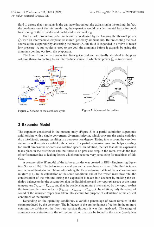
The combined cycle considered in this study is shown in Figure 2. The functioning is thatof a water-ammonia absorption machine to which a turbine is coupled in parallel with thecooling production. On the solution side, a first line of solution rich in ammonia circulatesfrom the absorber to the generator and is pressurized by a pump. A second line comprising anexpansion valve returns the poor solution to the absorber. An economizer allows preheatingthe rich solution thanks to the poor solution heat. In the generator, a supply of heat at lowtemperature allows the desorption of steam, mainly consisting of ammonia, from the solu-tion. The division of the steam flows is done directly at the exit of the generator so that therectification (purification of the steam from the water it contains) only takes place on the coldline in order to maximize both cooling and power production. This configuration was chosenfollowing previous studies on the optimal position of the rectifier [12].
On the electricity production side, the expander selection process leads to the identifica-tion of a partial admission impulse turbine as the best choice for the application, given thespecific speed and specific diameter calculated to be respectively around 5 and 13 [15]. Theturbine considered in this study for the production of the power Wt is therefore an axial mi-cro turbine characterized by a distributor composed of a single converging-diverging injector.Before the turbine, a superheater provides the power Qsh, to increase the temperature of the
fluid to ensure that it remains in the gas state throughout the expansion in the turbine. In fact,the condensation of the mixture during the expansion would be a detrimental factor for goodfunctioning of the expander and could lead to its breaking.
On the cold production side, ammonia is condensed by exchanging the thermal powerQc with an intermediate temperature source (generally ambient air). Before cooling the coldsource at the evaporator by absorbing the power Qe, the fluid is expanded in a valve to reachlow pressure. A sub-cooler is used to pre-cool the ammonia before it expands by using theammonia coming out from the evaporator.
The flows from the two production lines get mixed and are finally absorbed in the poorsolution thanks to cooling by an intermediate source to which the power Qa is transferred.
Figure 2. Scheme of the combined cycle Figure 3. Scheme of the turbine
3 Expander Model
The expander considered in the present study (Figure 3) is a partial admission supersonicaxial turbine with a single convergent-divergent injector, which converts the entire enthalpydrop into kinetic energy, resulting in a zero reaction degree. Taking into account the very lowsteam mass flow rates available, the choice of a partial admission machine helps avoidingtoo small dimensions or excessive rotation speeds. In addition, the fact that all the expansiontakes place in the distributor and that there is no pressure drop in the rotor, avoids the lossof performance due to leaking losses which can become very penalizing for machines of thissize.
A compressible 1D model of the turbo-expander was created in EES - Engineering Equa-tion Solver - [16]. The behavior as a real gas and a two-phase mixture of the fluid is takeninto account thanks to correlations describing the thermodynamic state of the water-ammoniamixture [17]. In the calculation of the sonic conditions and of the treated mass flow rate, thecondensation of the mixture during the expansion is taken into account by making the en-thalpy balance under the assumption that the liquid phase and the vapor phase are at the sametemperature Tliq,sat = Tvap,sat and that the condensing mixture is entrained by the vapor, so thatthe two have the same velocity (Cliq,sat = Cvap,sat = Cmixture). In addition, only the speed ofsound of the saturated vapor was taken into account for purpose of calculation of the criticalconditions of the mixture.
Depending on the operating conditions, a variable percentage of water remains in thesteam produced by the generator. The influence of the ammonia mass fraction in the mixtureentering the turbine on the flow rate passing through it was first analyzed. The range ofammonia concentrations in the refrigerant vapor that can be found in the cycle (rarely less
3
E3S Web of Conferences 312, 08018 (2021) https://doi.org/10.1051/e3sconf/20213120801876° Italian National Congress ATI

than 90%) has little influence on the mass flow rate treated by the distributor: for example forinlet conditions of 12 bar and 120 °C there is a maximum reduction of 3.15% in the case of amixture with an ammonia mass fraction of 90% compared to the case of pure ammonia.
Figure 4. Turbine mass flow rate characteristic fixing the total inlet pressure equal to 12 bar (a), andtotal outlet pressure equal to 4 bar (b)
Figures 4a and 4b show the injector mass flow rate characteristic as a function of thetotal outlet pressure, setting the total inlet pressure (Figure 4a) and vice versa (Figure 4b) fordi↵erent isentropic efficiencies of the injector in the case of pure ammonia.
A slight pressure di↵erence is sufficient to achieve the blocking condition and maximumflow through the sonic section of the injector. In the case of injector isentropic efficiency equalto one, the outlet to inlet pressure ratio sufficient to achieve sonic conditions in the minimumsection, βlim, is equal to 0.916, close to that calculable by the classical relations of ideal gasesusing an adiabatic index k = cp/cv defined as the arithmetic mean of the values relatingto upstream and downstream conditions [18]. As the isentropic efficiency of the injectordecreases, the βlim required to achieve sonic conditions decreases as does the maximum flowrate treated. In fact, lower injector efficiciencies correspond to greater total pressure lossesand therefore to a greater pressure variation necessary to reach the critical conditions. On theother hand, these conditions correspond to lower pressures and higher temperatures resultingin a decrease in fluid density and mass flow. The isentropic efficiency of the injector also hasa strong influence on the entry velocity into the rotor and is therefore a determining factor forthe overall efficiency of the machine. Figure 4b shows the same flow characteristic, settingthe pressure downstream of the injector and varying that upstream.
An energy balance allows calculating the entry speed into the rotor; this is used to findthe ideal work Wid exchanged by the fluid with the moving blades using Euler equation [19]Wid = U(Cu1 − Cu2). The velocities triangle is shown in 3, where U indicates the rotationspeed of the turbine, C1, W1 and β1 are the absolute velocity,relative velocity and angle ofthe relative velocity at the rotor inlet, C2, W2 and β2 are the same quantities at the exit of therotor, and βblade is the constructive angle of the blade. From the maximum theoretical workthat can be produced from the input kinetic energy, loss terms must be subtracted. Theseare commonly divided into incidence loss, passage loss, friction loss and windage loss. Thepartialization increases the loss term due to the ventilation e↵ect and if the turbine is stronglypartialized, the blades only stay in the active region for a short time, making full intake lossesnegligible compared to the partial intake ones [20].
4
E3S Web of Conferences 312, 08018 (2021) https://doi.org/10.1051/e3sconf/20213120801876° Italian National Congress ATI
than 90%) has little influence on the mass flow rate treated by the distributor: for example forinlet conditions of 12 bar and 120 °C there is a maximum reduction of 3.15% in the case of amixture with an ammonia mass fraction of 90% compared to the case of pure ammonia.
Figure 4. Turbine mass flow rate characteristic fixing the total inlet pressure equal to 12 bar (a), andtotal outlet pressure equal to 4 bar (b)
Figures 4a and 4b show the injector mass flow rate characteristic as a function of thetotal outlet pressure, setting the total inlet pressure (Figure 4a) and vice versa (Figure 4b) fordi↵erent isentropic efficiencies of the injector in the case of pure ammonia.
A slight pressure di↵erence is sufficient to achieve the blocking condition and maximumflow through the sonic section of the injector. In the case of injector isentropic efficiency equalto one, the outlet to inlet pressure ratio sufficient to achieve sonic conditions in the minimumsection, βlim, is equal to 0.916, close to that calculable by the classical relations of ideal gasesusing an adiabatic index k = cp/cv defined as the arithmetic mean of the values relatingto upstream and downstream conditions [18]. As the isentropic efficiency of the injectordecreases, the βlim required to achieve sonic conditions decreases as does the maximum flowrate treated. In fact, lower injector efficiciencies correspond to greater total pressure lossesand therefore to a greater pressure variation necessary to reach the critical conditions. On theother hand, these conditions correspond to lower pressures and higher temperatures resultingin a decrease in fluid density and mass flow. The isentropic efficiency of the injector also hasa strong influence on the entry velocity into the rotor and is therefore a determining factor forthe overall efficiency of the machine. Figure 4b shows the same flow characteristic, settingthe pressure downstream of the injector and varying that upstream.
An energy balance allows calculating the entry speed into the rotor; this is used to findthe ideal work Wid exchanged by the fluid with the moving blades using Euler equation [19]Wid = U(Cu1 − Cu2). The velocities triangle is shown in 3, where U indicates the rotationspeed of the turbine, C1, W1 and β1 are the absolute velocity,relative velocity and angle ofthe relative velocity at the rotor inlet, C2, W2 and β2 are the same quantities at the exit of therotor, and βblade is the constructive angle of the blade. From the maximum theoretical workthat can be produced from the input kinetic energy, loss terms must be subtracted. Theseare commonly divided into incidence loss, passage loss, friction loss and windage loss. Thepartialization increases the loss term due to the ventilation e↵ect and if the turbine is stronglypartialized, the blades only stay in the active region for a short time, making full intake lossesnegligible compared to the partial intake ones [20].
The incidence losses are expressed as follows [21]:
∆hi =12
cos2(β1 − βblade)W21 (1)
Passage losses due to friction in the blade channels are taken into account as [22]:
∆hp =12
(1 − 2)W21 (2)
where = 0.99 − 2.28∆β104 − 4.97
180−∆β and ∆β = β1 − β2
The windage loss is calculated as follows [23]:
∆hw =kwdmb1✏⇢U3
m(3)
where ⇢ is the density in the rotor, b1 is the height of the blade, dm the average diameter ofthe rotor, U is rotational speed of the turbine and kw = 0.6
pb1.
Finally, introducing a coefficient kd = 1.2 ·10−3 loss due to the friction on the disc is [23]:
∆hd =kdd2
m⇢U3
m(4)
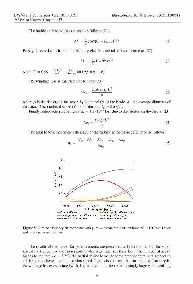
The total to total isentropic efficiency of the turbine is therefore calculated as follows:
⌘tt =Wid − ∆hi − ∆hp − ∆hw − ∆hd
∆his(5)
Figure 5. Turbine efficiency characteristic with pure ammonia for inlet condition of 120 °C and 12 barand outlet pressure of 5 bar
The results of the model for pure ammonia are presented in Figure 5. Due to the smallsize of the turbine and the strong partial admission rate (i.e. the ratio of the number of activeblades to the total) ✏ = 3.7%, the partial intake losses become preponderant with respect toall the others above a certain rotation speed. It can also be seen that for high rotation speeds,the windage losses associated with the partialization take an increasingly large value, shifting
5
E3S Web of Conferences 312, 08018 (2021) https://doi.org/10.1051/e3sconf/20213120801876° Italian National Congress ATI

the maximum efficiency of the turbomachine (52%) to lower rotation speeds compared to thetheoretical curve, obtained in the absence of losses in the rotor, from about 100,000 rpm toabout 60,000 rpm.
Figure 6. Turbine power characteristic with pure ammonia for an inlet temperature of 120 °C and outletpressure of 5 bar for di↵erent inlet pressure values
Figure 6 shows the power produced by the turbine for di↵erent inlet pressure values. Asthe inlet pressure increases, the power produced also increases, and its maximum value movesto higher rotation speeds.
4 Integrated cycle model
A numerical model of the presented absorption cycle was developed. For each component,the energy and mass balance equations are formulated under the steady state assumption. Themodel of heat exchangers is based on fixed pinch point values, pressure drops and efficiencydetermined from previous experimental experiences [23] and it is assumed that the mixtureis at saturation at the outlet of each exchanger (except for an imposed superheating at theevaporator outlet). To complete the development of the combined cycle, the turbine modelis integrated into the absorption machine model, together with a superheater, modeled as anadjustable power supply to the fluid. To estimate the efficiency of the cold production of thecycle, the cooling COP is defined as follows:
COP =Qe
Qg · rs(6)
where in the denominator the power supplied at the generator Qg is multiplied for theratio rs between the mass flow rate passing through the evaporator and the vapour mass flowrate desorbed at the generator, to take into account the fact that not all the vapour producedis used for the production of the cooling power Qe. On the other hand, the efficiency of thepower cycle is calculated as follows:
⌘power =Wt
Qg · (1 − rs) + Qsh(7)
6
E3S Web of Conferences 312, 08018 (2021) https://doi.org/10.1051/e3sconf/20213120801876° Italian National Congress ATI

the maximum efficiency of the turbomachine (52%) to lower rotation speeds compared to thetheoretical curve, obtained in the absence of losses in the rotor, from about 100,000 rpm toabout 60,000 rpm.
Figure 6. Turbine power characteristic with pure ammonia for an inlet temperature of 120 °C and outletpressure of 5 bar for di↵erent inlet pressure values
Figure 6 shows the power produced by the turbine for di↵erent inlet pressure values. Asthe inlet pressure increases, the power produced also increases, and its maximum value movesto higher rotation speeds.
4 Integrated cycle model
A numerical model of the presented absorption cycle was developed. For each component,the energy and mass balance equations are formulated under the steady state assumption. Themodel of heat exchangers is based on fixed pinch point values, pressure drops and efficiencydetermined from previous experimental experiences [23] and it is assumed that the mixtureis at saturation at the outlet of each exchanger (except for an imposed superheating at theevaporator outlet). To complete the development of the combined cycle, the turbine modelis integrated into the absorption machine model, together with a superheater, modeled as anadjustable power supply to the fluid. To estimate the efficiency of the cold production of thecycle, the cooling COP is defined as follows:
COP =Qe
Qg · rs(6)
where in the denominator the power supplied at the generator Qg is multiplied for theratio rs between the mass flow rate passing through the evaporator and the vapour mass flowrate desorbed at the generator, to take into account the fact that not all the vapour producedis used for the production of the cooling power Qe. On the other hand, the efficiency of thepower cycle is calculated as follows:
⌘power =Wt
Qg · (1 − rs) + Qsh(7)
Table 1 shows the strong impact that the integration of the turbine has on the cycle evenat the nominal operating point, characterized by a generator temperature Tg = 100°C andpower Qg = 15 kW, ambient temperature Ta = 25°C and cooling production temperatureTe = 5°C. In fact, once the turbine line is open, much of the mass flow rate produced by thegenerator is deviated towards the expander, whose treated mass flow rate solely depends onthe inlet- outlet pressure di↵erence. The refrigerant vapour mass flow rate division betweenthe turbine and evaporator lines has a strong impact on the power exchanged by the variousheat exchangers but has no influence on the high and low pressure of the cycle, definedrespectively by the condenser and evaporator temperature. Also the ammonia concentrationin the di↵erent parts of the cycle remains una↵ected by the presence of the turbine, withthe only di↵erence that, as the rectification takes place after stream division, the ammoniaconcentration on the power line remains the same as the one at the generator outlet.
Qa Qc Qe Wt Qsh mevap mturb
[kW] [kW] [kw] [kW] [kW] [kg/h] [kg/h]Turbine line closed 12.38 9.83 9.21 0 0 28.2 0Turbine line open 13.62 4.39 4.06 0.45 0.30 12.45 17.13
Table 1. Influence of the turbine on the cycle at the nominal operating point.
First, the influence of the generator on the cycle is studied in terms of power supplied andtemperature. If a generator temperature is set, there is a minimum power to supply it to beable to produce the steam mass flow rate required by the turbine. When the power supplied tothe generator increases, the mass flow rate of produced steam increases and, as the mass flowrate treated by the turbine in chocking conditions does not change, the value of the ratio rs
must increases as well as the mass flow passing through the refrigeration cycle and thereforethe cooling power produced.
For a set power supplied to the generator, a higher generator temperature implies a reduc-tion in the mass flow rate of steam produced because of the higher sensible heat transferredto the solution, resulting in a decrease in the mass flow circulating in the cold part of thecircuit. Therefore, the minimum generator power for the cycle to operate in combined modeincreases from 8.5 kW for generator temperatures of 100 °C to about 10 kW for tempera-tures of 150 °C. The above was obtained under the assumption of a cooling demand at 0 °C.Equation 6 shows that the cooling power produced is proportional to the percentage massflow rate passing through the cold part of the circuit (rs), but also to the COP, whose increas-ing - decreasing tendency with the generator temperature Tg depends strongly on the coolingproduction temperature Te.
The cooling production temperature is indeed a fundamental parameter in the characteri-zation of the behavior of the cycle and exerts a strong influence on the electrical and coolingpower produced by the cycle, on its efficiency and on the optimum temperature of the hotsource as shown in Figure 7a and Figure 7b, where the power supplied at the generator is of10 kW and the ambient temperature 25°C.
The influence of the condensation temperature Tc on the cycle (Figure 8) is then analyzed.An increase in this intermediate temperature leads to an increase in the maximum cycle pres-sure and thus in the pressure ratio available to the turbine. Therefore the power produced andthe mass flow rate treated by the expander increase significantly. On the contrary, the coolingpower produced undergoes a decrease due to the lower mass flow rate circulating through thecold part of the cycle, and the change in the COP. On the other hand, an increase in the tem-
7
E3S Web of Conferences 312, 08018 (2021) https://doi.org/10.1051/e3sconf/20213120801876° Italian National Congress ATI
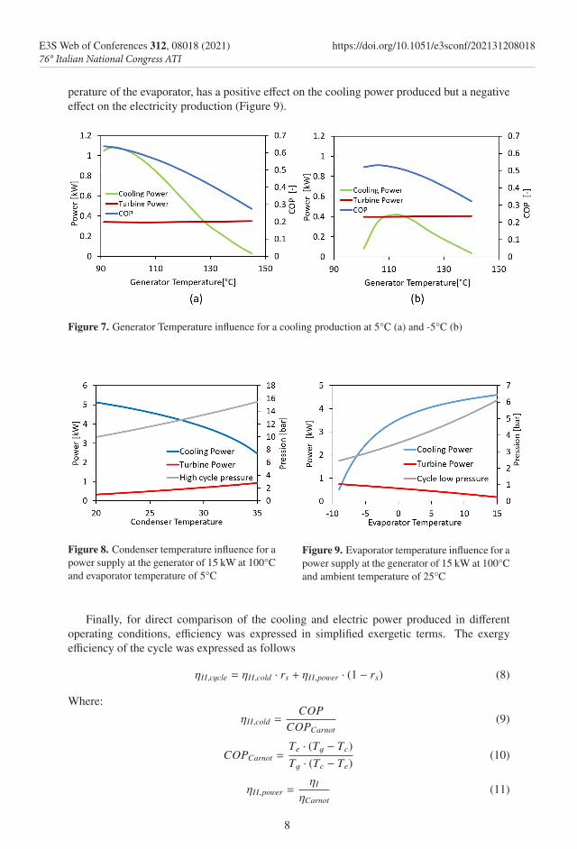
perature of the evaporator, has a positive e↵ect on the cooling power produced but a negativee↵ect on the electricity production (Figure 9).
Figure 7. Generator Temperature influence for a cooling production at 5°C (a) and -5°C (b)
Figure 8. Condenser temperature influence for apower supply at the generator of 15 kW at 100°Cand evaporator temperature of 5°C
Figure 9. Evaporator temperature influence for apower supply at the generator of 15 kW at 100°Cand ambient temperature of 25°C
Finally, for direct comparison of the cooling and electric power produced in di↵erentoperating conditions, efficiency was expressed in simplified exergetic terms. The exergyefficiency of the cycle was expressed as follows
⌘II,cycle = ⌘II,cold · rs + ⌘II,power · (1 − rs) (8)
Where:⌘II,cold =
COPCOPCarnot
(9)
COPCarnot =Te · (Tg − Tc)Tg · (Tc − Te)
(10)
⌘II,power =⌘I
⌘Carnot(11)
8
E3S Web of Conferences 312, 08018 (2021) https://doi.org/10.1051/e3sconf/20213120801876° Italian National Congress ATI

perature of the evaporator, has a positive e↵ect on the cooling power produced but a negativee↵ect on the electricity production (Figure 9).
Figure 7. Generator Temperature influence for a cooling production at 5°C (a) and -5°C (b)
Figure 8. Condenser temperature influence for apower supply at the generator of 15 kW at 100°Cand evaporator temperature of 5°C
Figure 9. Evaporator temperature influence for apower supply at the generator of 15 kW at 100°Cand ambient temperature of 25°C
Finally, for direct comparison of the cooling and electric power produced in di↵erentoperating conditions, efficiency was expressed in simplified exergetic terms. The exergyefficiency of the cycle was expressed as follows
⌘II,cycle = ⌘II,cold · rs + ⌘II,power · (1 − rs) (8)
Where:⌘II,cold =
COPCOPCarnot
(9)
COPCarnot =Te · (Tg − Tc)Tg · (Tc − Te)
(10)
⌘II,power =⌘I
⌘Carnot(11)
⌘Carnot = 1 − Tc
Tg(12)
As an example, the below given figure shows how, for a generator temperature of 100°C,decreasing the evaporator temperature increases the power produced by the turbine while itdecreases the cooling power produced, but a maximum of the second principle efficiency forthe system can be found at around -5°C. In the same way, fixing a desired temperature forthe cold production, an optimum generator temperature, maximizing the second principleefficiency, can be found.
Figure 10. Cycle performance as a function of the evaporator temperature for a power input of 15 kWat 100°C at the generator and an ambient temperature of 25 °C
5 Conclusions
An impulse turbine has a number of advantages compared to volumetric expanders, includingthe lower influence of leaking losses, which play a large role in very small machines.
The expander achieves chocking conditions with low expansion ratios, above which themass flow rate in the turbine no longer changes. The power produced by the turbine is highlydependent on its rotation speed and optimum operation appears to be around 50,000 - 70,000rpm depending on operating conditions.
The increase in temperature of the hot source feeding the generator seems to have nomajor e↵ect on the power produced by the turbine because it is accompanied by a reductionin the treated mass flow rate. On the other hand, the influence of the temperature of thecondenser (generally cooled by the ambient air) seems strong on the electricity and coolingproduction which are respectively proportional and inversely proportional to the intermediatesource temperature. The evaporator temperature turns out to be the most influential parame-ter: its reduction has a positive e↵ect on electricity production and a negative one on coolingproduction, thus emphasizing the importance of a preliminary definition of the cooling pro-duction temperature when designing the system. This defined, the generator temperature canbe set in order to maximise the power production, the cooling production or second principleefficiency.
Finally, in the lack of possibility of regulating its mass flow, the turbine sets strict limitsin terms of acceptable operating conditions for the cycle. For this reason, the addition of aregulation system to the model is being studied for application to the experimental setup.
9
E3S Web of Conferences 312, 08018 (2021) https://doi.org/10.1051/e3sconf/20213120801876° Italian National Congress ATI

Aknoledgments: The authors would like to express their gratitude to the French Al-ternative Energies and Atomic Energy Commission and the Carnot Energies of the FutureInstitute. S. Braccio was supported by the CEA NUMERICS program, which has receivedfunding from the European Union’s Horizon 2020 research and innovation program underthe Marie Sklodowska-Curie grant agreement No 800945.
References
[1] K.E. Herold, R. Radermacher, S.A. Klein, Absorption Chillers and Heat Pumps (2016)[2] D.S. Ayou, J.C. Bruno, R. Saravanan, A. Coronas, An overview of combined absorption
power and cooling cycles (2013)[3] A. Khaliq, Applied Thermal Engineering 112, 1305 (2017)[4] F. Xu, D. Yogi Goswami, S. S. Bhagwat, Energy (2000)[5] G.P. Kumar, R. Saravanan, A. Coronas, Energy 128, 801 (2017)[6] J. Wang, Y. Dai, T. Zhang, S. Ma, Energy 34, 1587 (2009)[7] N. Voeltzel, H.T. Phan, N. Tauveron, B. Gonzalez, Q. Blondel, M. Wirtz, F. Boudehenn,
Proceedings of the ISES Solar World Congress 2019 and IEA SHC International Con-ference on Solar Heating and Cooling for Buildings and Industry 2019 pp. 2681–2690(2020)
[8] J. Muye, D.S. Ayou, R. Saravanan, A. Coronas, Applied Thermal Engineering 97, 59(2016)
[9] L.C. Mendoza, D.S. Ayou, J. Navarro-Esbrí, J.C. Bruno, A. Coronas, Applied ThermalEngineering 72, 258 (2014)
[10] G.K. Alexis, International Journal of Refrigeration 30, 1097 (2007)[11] A. Landelle, N. Tauveron, P. Haberschill, R. Revellin, S. Colasson, Applied Energy
(2017)[12] F. Boudéhenn, H. Demasles, J. Wyttenbach, X. Jobard, D. Chèze, P. Papillon, Energy
Procedia 30, 35 (2012)[13] N. Voeltzel, H.T. Phan, Q. Blondel, B. Gonzalez, N. Tauveron, Thermal Science and
Engineering Progress 19, 100650 (2020)[14] Q. Blondel, N. Tauveron, N. Caney, N. Voeltzel, Applied Sciences (Switzerland) (2019)[15] E. Balje (1962)[16] EES: Engineering Equation Solver|F-Chart Software:Engineering Software, http://
www.fchart.com/ees/, accessed on 27 June 2021[17] S. Ibrahim, O.M., Klein, Thermodynamic properties of ammonia-water mixtures., in
ASHRAE Trans.: Symposia, 21, 2, 1495 (1993)[18] J.D. Anderson (1982)[19] S. Dixon, C. Hall, Fluid Mechanics and Thermodynamics of Turbomachinery (2010),
ISBN 9781856177931[20] S.Y. Cho, C.H. Cho, C. Kim, JSME International Journal, Series B: Fluids and Thermal
Engineering 49, 1290 (2007)[21] J.P. Czapla (2015)[22] M.H. Vavra, Aero-Thermodynamics and Flow in Turbomachines (John Wiley, 1960)[23] A. Capetti, Motori termici (UTET, 1964)
10
E3S Web of Conferences 312, 08018 (2021) https://doi.org/10.1051/e3sconf/20213120801876° Italian National Congress ATI
Related Documents