IJRET: International Journal of Research in Engineering and Technology eISSN: 2319-1163 | pISSN: 2321-7308 _______________________________________________________________________________________ Volume: 03 Issue: 10 | Oct-2014, Available @ http://www.ijret.org 182 STUDY OF THE EFFECTS OF CARBON AND GLASS FIBRE REINFORCEMENT AND OTHER FILLERS ON ELEVATED TEMPERATURE RESISTANT PROPERTIES OF ER MATRIX COMPOSITES Md Nadeem M 1 , K Chandrashekara 2 , Yathisha N 3 , Rudramurthy 4 1 Department of Mechanical Engineering, ATME College of Engineering, Mysore, Karnataka, India 2 Department of Mechanical Engineering, SJCE, Mysore Karnataka, India 3 Department of Mechanical Engineering, ATME College of Engineering, Mysore, Karnataka, India 4 Department of Mechanical Engineering, SJCE, Mysore Karnataka, India Abstract In the present study, composite materials required for elevated temperature applications were fabricated using vacuum bagging technique. Epoxy Resin (ER-VP401) was used as the matrix and Glass fibre was used as reinforcement. SiC, Al 2 O 3 and others were used as fillers to bring in elevated temperature resistance. These composites were subjected to mechanical tests like Tensile, Hardness and Impact test. Tribological tests like two body abrasion and Pin on disc (POD) were carried out. Tensile strength, hardness and impact energy were improved with increase in fillers content. Wear resistance also improved with increase in percentage of fillers substantially. SEM micrographs are used to explain the mechanism of the material strengthening at elevated temperatures. Keywords: Epoxy resin, Glass Fiber (GF), Al 2 O 3 , SiC, Elevated Temperature Resistance. --------------------------------------------------------------------***----------------------------------------------------------------- 1. INTRODUCTION The materials used to manufacture various products are supposed to fulfill several criteria before being approved. Some of the criteria are the results of regulation and legislation with the environmental and safety concerns and some are the requirements of the customers. Composite material is a combination of two or more materials to form a new material system with enhanced material properties. After being solely used for their electromagnetic properties (insulators and radar-domes), using composites to improve the structural performance of spacecraft and military aircraft became popular in the last two decades. Nowadays, cost reduction during manufacturing and operation are the main technology drivers. Fibers or particles embedded in matrix of another material are the best example of modern-day composite materials. For most structural applications in the current aircraft designs, polymer composites has been adequately used and implemented for a wide range of applications in areas where high temperatures are encountered. The usage of such composites, even for primary loadbearing structures in military fighters, transport aircraft, satellites and space vehicles has been beneficially realized. Attention is now focused on expanding the usage of such composites to other areas where temperatures could be higher in the range of 200-400 o C [1]. Multi-Walled Carbon Nanotubes functionalized with amino groups (MWCNT-NH2) via chemical modification of the carboxyl groups introduced on the surface of MWCNT. The thermal diffusivity and conductivity of all of the composites continuously improved with increasing content of fillers [2]. The behavior of Glass Fiber-Reinforced Polymer (GFRP) bars subjected to extreme temperatures is very critical for industrial applications. They evaluated the variation of mechanical properties of sand-coated GFRP reinforcing bars subjected to low temperatures (ranging from 0 to −100°C ) and elevated temperatures (ranging from 23 to 315°C). Tensile, shear and flexural properties improved as the glass fiber content increased [3]. The effect of addition of Silicon Carbide (SiC) filler in different weight percentages on physical properties, mechanical properties, and thermal properties of chopped glass fiber-reinforced epoxy composites has been investigated. The result showed that the physical and mechanical properties of SiC-filled glass fiber- reinforced epoxy composites were better than unfilled glass fiber-reinforced epoxy composites [4]. [5] Presented results of an experimental and analytical study about the mechanical behavior at elevated temperatures of Glass Fiber Reinforced Polymer (GFRP) pultruded profiles made of polyester resin and E-glass fibers. [6] observed the mechanical properties of Vapor Grown Carbon Nano fiber (VGCNF)polymer composites. They studied the structural and intrinsic mechanical properties of VGCNFs. Then the major factors (filler dispersion and distribution, filler aspect ratio, adhesion and interface between filler and polymer matrix) affecting the mechanical properties of VGCNF/polymer composites were presented. The effect of fiber content and fiber orientation on the strength of composites was studied to estimate the tensile strength out of fibre orientation and fibre content [7].

Study of the effects of carbon and glass fibre reinforcement and other fillers on elevated temperature resistant properties of er matrix composites
Jul 13, 2015
Welcome message from author
This document is posted to help you gain knowledge. Please leave a comment to let me know what you think about it! Share it to your friends and learn new things together.
Transcript

IJRET: International Journal of Research in Engineering and Technology eISSN: 2319-1163 | pISSN: 2321-7308
_______________________________________________________________________________________
Volume: 03 Issue: 10 | Oct-2014, Available @ http://www.ijret.org 182
STUDY OF THE EFFECTS OF CARBON AND GLASS FIBRE
REINFORCEMENT AND OTHER FILLERS ON ELEVATED
TEMPERATURE RESISTANT PROPERTIES OF ER MATRIX
COMPOSITES
Md Nadeem M 1
, K Chandrashekara 2, Yathisha N
3, Rudramurthy
4
1Department of Mechanical Engineering, ATME College of Engineering, Mysore, Karnataka, India
2Department of Mechanical Engineering, SJCE, Mysore Karnataka, India
3Department of Mechanical Engineering, ATME College of Engineering, Mysore, Karnataka, India
4Department of Mechanical Engineering, SJCE, Mysore Karnataka, India
Abstract In the present study, composite materials required for elevated temperature applications were fabricated using vacuum bagging
technique. Epoxy Resin (ER-VP401) was used as the matrix and Glass fibre was used as reinforcement. SiC, Al2O3 and others
were used as fillers to bring in elevated temperature resistance. These composites were subjected to mechanical tests like Tensile,
Hardness and Impact test. Tribological tests like two body abrasion and Pin on disc (POD) were carried out. Tensile strength,
hardness and impact energy were improved with increase in fillers content. Wear resistance also improved with increase in
percentage of fillers substantially. SEM micrographs are used to explain the mechanism of the material strengthening at elevated
temperatures.
Keywords: Epoxy resin, Glass Fiber (GF), Al2O3, SiC, Elevated Temperature Resistance. --------------------------------------------------------------------***-----------------------------------------------------------------
1. INTRODUCTION
The materials used to manufacture various products are
supposed to fulfill several criteria before being approved.
Some of the criteria are the results of regulation and
legislation with the environmental and safety concerns and
some are the requirements of the customers. Composite
material is a combination of two or more materials to form a new material system with enhanced material properties.
After being solely used for their electromagnetic properties
(insulators and radar-domes), using composites to improve
the structural performance of spacecraft and military aircraft
became popular in the last two decades. Nowadays, cost
reduction during manufacturing and operation are the main
technology drivers. Fibers or particles embedded in matrix
of another material are the best example of modern-day
composite materials.
For most structural applications in the current aircraft designs, polymer composites has been adequately used and
implemented for a wide range of applications in areas where
high temperatures are encountered. The usage of such
composites, even for primary loadbearing structures in
military fighters, transport aircraft, satellites and space
vehicles has been beneficially realized. Attention is now
focused on expanding the usage of such composites to other
areas where temperatures could be higher in the range of
200-400oC [1]. Multi-Walled Carbon Nanotubes
functionalized with amino groups (MWCNT-NH2) via
chemical modification of the carboxyl groups introduced on
the surface of MWCNT. The thermal diffusivity and
conductivity of all of the composites continuously improved
with increasing content of fillers [2]. The behavior of Glass
Fiber-Reinforced Polymer (GFRP) bars subjected to
extreme temperatures is very critical for industrial
applications. They evaluated the variation of mechanical properties of sand-coated GFRP reinforcing bars subjected
to low temperatures (ranging from 0 to −100°C ) and
elevated temperatures (ranging from 23 to 315°C). Tensile,
shear and flexural properties improved as the glass fiber
content increased [3]. The effect of addition of Silicon
Carbide (SiC) filler in different weight percentages on
physical properties, mechanical properties, and thermal
properties of chopped glass fiber-reinforced epoxy
composites has been investigated. The result showed that the
physical and mechanical properties of SiC-filled glass fiber-
reinforced epoxy composites were better than unfilled glass
fiber-reinforced epoxy composites [4]. [5] Presented results of an experimental and analytical study about the
mechanical behavior at elevated temperatures of Glass Fiber
Reinforced Polymer (GFRP) pultruded profiles made of
polyester resin and E-glass fibers. [6] observed the
mechanical properties of Vapor Grown Carbon Nano fiber
(VGCNF)polymer composites. They studied the structural
and intrinsic mechanical properties of VGCNFs. Then the
major factors (filler dispersion and distribution, filler aspect
ratio, adhesion and interface between filler and polymer
matrix) affecting the mechanical properties of
VGCNF/polymer composites were presented. The effect of fiber content and fiber orientation on the strength of
composites was studied to estimate the tensile strength out
of fibre orientation and fibre content [7].

IJRET: International Journal of Research in Engineering and Technology eISSN: 2319-1163 | pISSN: 2321-7308
_______________________________________________________________________________________
Volume: 03 Issue: 10 | Oct-2014, Available @ http://www.ijret.org 183
The F584/PW Pre-Impregnated materials (prepregs)
presented the highest values of tensile strength while the
highest modulus results were obtained for the 8HS
composite laminates [8]. [9] Conducted a research on epoxy
resin polymers reinforced with natural fibers like Sisal,
Banana and Roselle and three hybrid combinations of any two fibers. Less elongation and fiber pull out and brittle
nature of fracture were observed in fiber based composites
while more elongation, fiber pull out and partial brittle
nature of fracture were observed in hybrid composites. It
was seen from the results that well dispersed Nano particles
of CaCO3 up to the weight percentage of 15 increases the
impact strength of the composite [10]. [11] Conducted
impact tests on aluminum filled milled (carbon and glass)
fiber reinforced epoxy based polymer composites. The
milled fiber addition slightly increased the impact resistance
of the composites. [12] Studied the impact resistance of epoxy based composites reinforced with fiber and hybrid of
sisal, banana and Roselle fibers. The results showed that the
hybrid composites absorbed more impact energy before
fracture. The greater level of fiber pull out observed in
specimens fabricated using hybrid reinforcement, leads to
superior impact strength. The effect of the reinforcement of
thermosetting polyester with short glass fibers on
mechanical properties and tribological behavior was studied.
The friction and wear-behavior as a function of sliding
speed and fiber-glass proportion (0 to 50%). Wear resistance
behavior increased with increase in glass fiber and filler
content [13]. [14] Investigated that the tribological behavior was found to depend on the filler materials in the tested
composites and better results were obtained for the
composite containing solid lubricants
(Polytetrafluoroethylene (PTFE) and graphite). [15]
Observed that the wear loss increases with increase in
normal load. The optimum wear reduction was obtained
with 40% fiber content.
The objective of the present study is to investigate the effect
of filler materials on the mechanical properties of the
selected polymer matrix composite at elevated temperature. The composition of the specimens is given in table-1.
2. MATERIALS AND METHODS
Table-1: composition of the specimens
Components' percentage
by weight
Specimen No
1 2 3 4 5
Epoxy Resin 50 50 50 50 50
Activated Carbon Powder 10 10 10 10 10
Chopped E - Glass fiber 10 10 10 10 10
Sodium Sulphide ( Na2S ) 5 5 5 5 5
Sintered Clay 5 5 5 5 5
Silicon Carbide ( SiC ) 20 15 10 5 0
Aluminium Oxide( Al2O3) 0 5 10 15 20
2.2 Specimen Preparation and Experimental Set Up
Table I gives the materials used in the present study. Epoxy
resin is kept constant at 50 Wt%. Activated carbon powder
and chopped E glass fibre were kept at 10 Wt% respectively,
sodium sulphide and sintered clay were used as fillers to
bring in elevated temperature resistance properties and they
were kept at 5 Wt% each. Silicon carbide (SiC) and
Aluminum oxide (Al2O3) were varied from 0-20 Wt% each.
First the materials are weighed as required, and then they are
put together and mixed well. The mixture is then poured into a prepared mould of the required thickness. It should be
noted that the epoxy resin and hardener start to set i.e. start
solidifying after 30 minutes of mixing and hence, the
mixture should be poured into the mould before the setting
time. The mixture is poured in excess and suitable weights
are applied on it. Similarly, five different compositions are
poured in separate moulds by varying the SiC and Al2O3
content while keeping all the other weight percentages
constant. The content of SiC and Al2O3 are varied in steps of
five percent in such a way that in any composition, the sum
of SiC and Al2O3is 20 percent of the total weight. The moulds are then left for 24 hours to solidify and cure at
room temperature. After solidification, the specimens are
removed from the mould and post cured at 100oC for 2
hours in a hot air oven. The specimens are then taken out
and labeled. The specimens are then marked as per the test
standards. Specimens were prepared for tensile, impact
strength and wear tests. Figure-1 shows the specimen
preparation pictures.
(a) Weighing the constituents (b) Mixing the constituents
in right Proportion
(c) Pouring the mixture into the (d) Specimens Moulds
Fig-1- Preparation of Specimens
To determine the mechanical properties of the material the
following tests were conducted. A. Tensile test- Tensile tests were conducted according
to the ASTM D-638. Computerized Universal Testing
Machine (UTM) used for this purpose and the loading
arrangement is shown in Figure. 2(a). Specifications
are also mentioned. The dimension of the tensile

IJRET: International Journal of Research in Engineering and Technology eISSN: 2319-1163 | pISSN: 2321-7308
_______________________________________________________________________________________
Volume: 03 Issue: 10 | Oct-2014, Available @ http://www.ijret.org 184
specimen was 165 mm x 19 mm x 3.2 mm. Gauge
length was 50 mm. Results were used to calculate the
tensile strength of composite samples.
B. Impact test - Izod impact tests were conducted on V-
notched composite specimen according to ASTM
D256. A Pendulum impact tester, shown in Figure 2(b) was used for this purpose. Dimension of the
specimen were 64 mm x 12.5 mm x 3.2 mm. The
pendulum impact testing machine ascertains the
impact strength of the material by shattering the
specimen with a pendulum hammer, measuring the
spent energy and relating it to the cross section of the
specimen. The respective values of impact energy of
different specimen are recorded directly from the
digital indicator and reported.
C. Hardness test - Shore-D hardness tests were
conducted on specimen according to ASTM D2240 using Durometer shown in Figure 2(c). The hardness
tester is placed on the specimen and pressure is
applied so that the flats underneath the tester touch
the surface of the specimen. The readings are taken
directly from the dial. The specimens are then heated
to different temperatures and the readings are taken to
determine the variation in the hardness of the
specimen with respect to temperature.
D. Wear test - Wear tests were conducted according to
the ASTM using Pin on Disc Machine (POD).The
machine and its specifications are given in Figure
2(d). Dry sliding tests were conducted at ambient conditions with the loads of 4 Kg, 8 Kg, 12 Kg and
16 Kg. Disc speed was kept at 1000rpm with track
diameter of 40mm, resulting in a sliding velocity of
3.92 m/s. The tests were conducted for two minutes
or the length of time until the specimen withstands
the maximum load and failed whichever being the
earliest. The temperature of the tip of the specimen
was registered using the optical pyrometer. Wear of
the materials considered was measured by loss in
length which is then converted into wear volume
using the measured cross-sectional area data. The specific Wear rate (Ks) was calculated from the below
equation (1).
𝐾𝑠 =∆𝑉
𝑃 × 𝐷 𝑖𝑛
𝑚3
𝑁 −𝑚
Where, ∆V is the volume loss in m3, P is the load in
Newton; D is the sliding distance in meters.
(a) Tensile testing machine setup (UTM) (b)
Computerized impact testing machine
(c) Shore-D hardness testing machine (d) Pin on disc
machine
Fig-2- Testing machines
3. RESULTS AND DISCUSSIONS
Physical and mechanical properties describe the behavior of
materials when they are used in practical applications. The
properties such as hardness describe the physical state of the
system. The mechanical property of the material is a
measure of the behavior of the material under different
loading conditions. Tests were done to notice the effect of
variation of filler content on the physical and mechanical
properties and the optimum filler loading of carbon-glass
reinforced polymer composites at which specific Specific
Wear rate is least.
3.1 Effect of SiC and Al2O3 on Tensile Strength of
Carbon-Glass Reinforced Polymer Composites
The tensile strength is an engineering value that is calculated
by dividing the maximum load on the material by the initial
cross sectional area of the test specimen. The Table II shows
the results obtained during the tensile test conducted on all
the five specimens.
Table-:2 tensile strength of cgrp composites
Specimen
No. Filler Content
Ultimate Tensile
Strength ( MPa )
1 20% SiC, 0%
Al2O3 15.38
2 15% SiC, 05%
Al2O3 17.31
3 10% SiC, 10%
Al2O3 19.35
4 05% SiC, 15% Al2O3
20.98
5 0% SiC, 20%
Al2O3 25.28
The graph for the tensile strength is shown in Figure 3.1

IJRET: International Journal of Research in Engineering and Technology eISSN: 2319-1163 | pISSN: 2321-7308
_______________________________________________________________________________________
Volume: 03 Issue: 10 | Oct-2014, Available @ http://www.ijret.org 185
Fig 3.1 – Effect of SiC and Al2O3 on Ultimate Tensile
Strength (UTS) on CGRP Composites
From the graph 3.1, it can be seen that the tensile strength is
highest in the composite with 20% Al2O3 and no SiC, and
lowest in that with 20% SiC and no Al2O3. The tensile
strength increases proportionally with the increase in Al2O3
content and decrease in SiC content since the tensile
strength of Al2O3 is higher than that of SiC. But complete
absence of SiC in the fifth composite specimen results in a
higher tensile strength which is not in proportion with the tensile strengths of other specimens. This is due to the
presence of higher percentage of Al2O3 alone and no SiC.
The Al2O3 particles which fill the composite, due to their
higher tensile strength can withstand more loads and transfer
it to the adjacent particle at the same time, thus reducing the
load concentration at a single point which in turn reduces
the stress concentration thereby increasing the ultimate
tensile strength of the specimen. Also, the Al2O3 particles
which are smaller than the SiC particles have a higher
density compared to the SiC density. The higher density
results in a uniform and continuous distribution of the filler
and lower bonding surface resulting in increase in bonding strength which also results in increase in the tensile strength
of the specimen.
The specimen with 20% SiC and 0% Al2O3 has the least
tensile strength of the five compositions. This is due to the
low tensile strength of SiC and its larger particle size. While
the low tensile strength of SiC hampers the tensile strength
of the specimen directly by failing at lower loads, the larger
particle size of SiC results in a discrete distribution of filler
along with an increase in bonding surface area which
decreases the binding strength, thereby decreases the tensile strength of the specimen.
3.2 Effect of SiC and Al2O3 on Impact Strength of
Carbon-Glass Reinforced Polymer Composites
The material’s resistance to fracture is known as toughness.
It is the energy absorbed by the material before fracture and
is expressed in terms of the same. A ductile material can
absorb considerable amount of energy before fracture while
a brittle material absorbs very little energy before fracture.
Table IIIshows the results obtained during the impact test
conducted on all the five specimens.
Table-3: Impact Strength Of Cgrp Composites
Specimen
No. Filler Content
Impact
Energy ( J )
1 20% SiC, 0% Al2O3 1
2 15% SiC, 05%
Al2O3 0.45
3 10% SiC, 10%
Al2O3 0.45
4 05% SiC, 15%
Al2O3 1.3
5 0% SiC, 20% Al2O3 0.6
The graph for the impact strength is shown in Figure 3.2
Fig. 3.2 - Effect of SiC and Al2O3 impact strength on CGRP
Composites
From table III, it is observed that the impact energy is the highest for the composite having 05%SiC and 15%Al2O3.
The fracture toughness for SiC is 1.5 times greater than that
of Al2O3.Glass fiber has least fracture toughness, at the
highest percentage of silicon impact strength is 1J, but it has
decreased to 0.45J.It has remained the same for the further
decrease in SiC, indicating the fracture toughness of both
SiC and Al2O3 are contributing to the increase in impact
strength, contribution from Al2O3 being higher. This
emphasizes the further increase in Al2O3 percentage has
increased the impact strength significantly (up to 15% of
Al2O3).
The conclusion is that relatively lesser percentage of SiC is
a must for increase in impact strength irrespective of
increase in Al2O3.This observation is evident as the impact
strength has decreased drastically for 0% of SiC.
3.3 Effect of SiC and Al2O3 on Wear Resistance of
Carbon-Glass Reinforced Polymer Composites
Wear is the sideways erosion of material on a solid surface
due to the action of another surface. A material is said to
possess good wear properties when less amount of material
gets eroded due to the friction. Table 3.3 shows the results
obtained during the wear test conducted on all the
specimens.
15
20
25
30
Filler Content
UT
S (
MP
a)
00.20.40.60.81
1.21.4
Filler Content
Imp
act E
ner
gy
(J)
IJRET: International Journal of Research in Engineering and Technology eISSN: 2319-1163 | pISSN: 2321-7308
_______________________________________________________________________________________
Volume: 03 Issue: 10 | Oct-2014, Available @ http://www.ijret.org 186
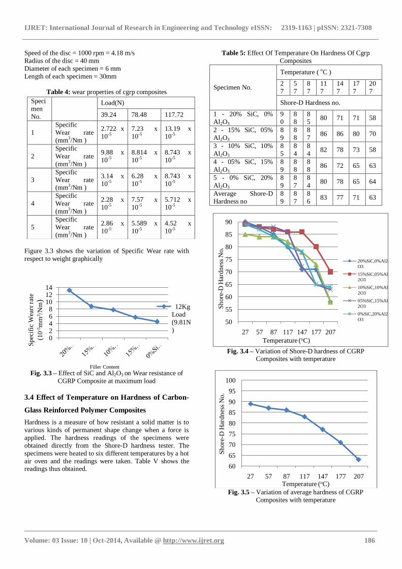
Speed of the disc = 1000 rpm = 4.18 m/s
Radius of the disc = 40 mm
Diameter of each specimen = 6 mm
Length of each specimen = 30mm
Table 4: wear properties of cgrp composites
Figure 3.3 shows the variation of Specific Wear rate with
respect to weight graphically
Fig. 3.3 – Effect of SiC and Al2O3 on Wear resistance of
CGRP Composite at maximum load
3.4 Effect of Temperature on Hardness of Carbon-
Glass Reinforced Polymer Composites
Hardness is a measure of how resistant a solid matter is to
various kinds of permanent shape change when a force is
applied. The hardness readings of the specimens were
obtained directly from the Shore-D hardness tester. The
specimens were heated to six different temperatures by a hot
air oven and the readings were taken. Table V shows the readings thus obtained.
Table 5: Effect Of Temperature On Hardness Of Cgrp
Composites
Specimen No.
Temperature ( oC )
2
7
5
7
8
7
11
7
14
7
17
7
20
7
Shore-D Hardness no.
1 - 20% SiC, 0%
Al2O3
9
0
8
8
8
5 80 71 71 58
2 - 15% SiC, 05%
Al2O3
8
9
8
8
8
7 86 86 80 70
3 - 10% SiC, 10%
Al2O3
8
5
8
4
8
4 82 78 73 58
4 - 05% SiC, 15%
Al2O3
8
9
8
8
8
8 86 72 65 63
5 - 0% SiC, 20%
Al2O3
8
9
8
7
8
4 80 78 65 64
Average Shore-D
Hardness no
8
9
8
7
8
6 83 77 71 63
Fig. 3.4 – Variation of Shore-D hardness of CGRP
Composites with temperature
Fig. 3.5 – Variation of average hardness of CGRP
Composites with temperature
02468
101214
12Kg
Load
(9.81N
)
Filler Content
Sp
ecif
ic W
earr
rate
(10
-5m
m3/N
m)
50
55
60
65
70
75
80
85
90
27 57 87 117 147 177 207
20%SiC,0%Al2
O3
15%SiC,05%Al
2O3
10%SiC,10%Al
2O3
05%SiC,15%Al
2O3
0%SiC,20%Al2
O3
Temperature (oC)
Sh
ore
-D H
ard
nes
s N
o.
60
65
70
75
80
85
90
95
100
27 57 87 117 147 177 207Temperature (oC)
Sh
ore
-D H
ardn
ess
No.
Speci
men
No.
Load(N)
39.24 78.48 117.72
1
Specific
Wear rate
(mm3/Nm )
2.722 x
10-5
7.23 x
10-5
13.19 x
10-5
2
Specific
Wear rate
(mm3/Nm )
9.88 x
10-5
8.814 x
10-5
8.743 x
10-5
3
Specific
Wear rate (mm3/Nm )
3.14 x
10-5
6.28 x
10-5
8.743 x
10-5
4
Specific
Wear rate
(mm3/Nm )
2.28 x
10-5
7.57 x
10-5
5.712 x
10-5
5
Specific
Wear rate
(mm3/Nm )
2.86 x
10-5
5.589 x
10-5
4.52 x
10-5

IJRET: International Journal of Research in Engineering and Technology eISSN: 2319-1163 | pISSN: 2321-7308
_______________________________________________________________________________________
Volume: 03 Issue: 10 | Oct-2014, Available @ http://www.ijret.org 187
It could be seen from the Table V and Fig 3.5 the average
Shore-D hardness value obtained at room temperature for
the entire specimen considered irrespective of the
percentage by weight of SiC and Al2O3 is 89. Similarly, the
average values of hardness for considered specimen at
temperatures greater than the room temperature is steps of 30oC upto 207oC are 87,86,83,77,71,63.
From 27oC (room temperature) to 117oC, the hardness value
has decreased by 6.7%, which is not very significant. From
147oC to 207oC, the percentage decreased in Shore-D
hardness is 18.2%, which is significant. This means that the
considered specimen can retain their hardness up to 120oC.
Hardness of the SiC is 2.3 times greater than that of Al2O3,
the thermal conductivity of SiC is 6.6 times greater than that
of Al2O3.Whereas,the coefficient of thermal expansion of
Al2O3 is 2 times greater than that of SiC.
At room temperature, the average value of Shore-D hardness
is about 89.This value has decreased slightly up to
87oC,from 87oC up to 117oC the decrease in value is about
3.48%.Further increase in temperature in steps of 30oC up to
207oC,the percentage decrease is 6.89%.
The reason is that higher percentage of SiC has contributed
to the average hardness of all the specimens considered up
till 117oC.Slight Decrease in hardness in this temperature
range is attributed to increase in percentage of Al2O3, which
has got comparatively higher hardness, beyond 117oC one must note that SiC percentage has decreased and Al2O3
percentage has increased.
By the order of magnitude of hardness of SiC and Al2O3 it is
evident that the hardness has decreased quite drastically up
to 207oC .The synergy of these fillers has come to play up to
117oC and it has seized to exist from 117oC to 207oC.
4. SEM MORPHOLOGY
Fig 4.1 – SEM micrograph (500 X Magnification) of CGRP
composite with subjected to tensile test
From the Table III, it is observed that tensile strength is
increasing with increase in percentage of Al2O3,it is 64.36%
increased which is very significant.
The variation is also linear; the increasing tensile strength up
to 15% Al2O3, for every 5% addition of Al2O3 increasing in
tensile strength is 10.91%.Whereas, increase in tensile
strength for 5% more addition of Al2O3 ,increases the tensile
strength is 20.49%.One can observe that, the order of
magnitude of increase in tensile strength for 5% more
addition is almost twice.
SiC has 410GPa elastic modulus, whereas Al2O3 has
300GPa,it is evident that increase in tensile strength for the
decrease in SiC is around 10% and increase in 5% of Al2O3
when SiC has become 0 is 20%.Hence,elastic modulus of
SiC and Al2O3 are contributing to the increase in overall
tensile strength.
These observations are also evident from SEM
micrographs(Fig-4.1). As could be seen from the plate,GF
have got pulled out from the matrix, whereas more GFs have
broken in a brittle manner. These surfaces bonding energy between GF and resin is lesser when compared with that of
Al2O3,SiC and other fillers. This means that the contribution
of GF for the increase in tensile strength is not significant. It
is the larger interfacial attractive forces between the fillers
and their properties which have contributed to the increase
in tensile strength. It can also be observed from SEM
micrographs that very few of these particles are still in their
location and these have not fractured.
Fig 4.2 – SEM micrograph (500 X Magnification) of CGRP
composite with subjected to Impact test
Fig 4.3 – SEM micrograph (1.0K X Magnification) of
CGRP composite with subjected to Impact test
IJRET: International Journal of Research in Engineering and Technology eISSN: 2319-1163 | pISSN: 2321-7308
_______________________________________________________________________________________
Volume: 03 Issue: 10 | Oct-2014, Available @ http://www.ijret.org 188
Figure 4.2 and 4.3 is showing SEM micrograph of the
specimen having 5% SiC and 15% Al2O3, giving the highest
value of impact strength. The main fractured constituent due
to impact load are glass fibers which have got the lowest
fracture toughness (1MPa m1/2
), these are indicated by the
fractured glass fibers appearing as bright cylindrical columns. Most of the other particles have got embedded in
the matrix including some broken GFs, this is appearing as
the darker fibrous spot.
Obviously, the increase in impact strength is basically due to
the presence of higher percentage of Al2O3 and lower
percentage of SiC.
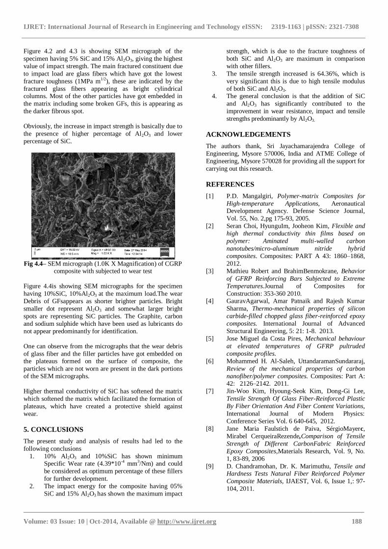
Fig 4.4– SEM micrograph (1.0K X Magnification) of CGRP
composite with subjected to wear test
Figure 4.4is showing SEM micrographs for the specimen
having 10%SiC, 10%Al2O3 at the maximum load.The wear
Debris of GFsappears as shorter brighter particles. Bright
smaller dot represent Al2O3 and somewhat larger bright
spots are representing SiC particles. The Graphite, carbon
and sodium sulphide which have been used as lubricants do
not appear predominantly for identification.
One can observe from the micrographs that the wear debris
of glass fiber and the filler particles have got embedded on the plateaus formed on the surface of composite, the
particles which are not worn are present in the dark portions
of the SEM micrographs.
Higher thermal conductivity of SiC has softened the matrix
which softened the matrix which facilitated the formation of
plateaus, which have created a protective shield against
wear.
5. CONCLUSIONS
The present study and analysis of results had led to the
following conclusions
1. 10% Al2O3 and 10%SiC has shown minimum Specific Wear rate (4.39*10-4 mm3/Nm) and could
be considered as optimum percentage of these fillers
for further development.
2. The impact energy for the composite having 05%
SiC and 15% Al2O3 has shown the maximum impact
strength, which is due to the fracture toughness of
both SiC and Al2O3 are maximum in comparison
with other fillers.
3. The tensile strength increased is 64.36%, which is
very significant this is due to high tensile modulus
of both SiC and Al2O3. 4. The general conclusion is that the addition of SiC
and Al2O3 has significantly contributed to the
improvement in wear resistance, impact and tensile
strengths predominantly by Al2O3.
ACKNOWLEDGEMENTS
The authors thank, Sri Jayachamarajendra College of
Engineering, Mysore 570006, India and ATME College of
Engineering, Mysore 570028 for providing all the support for
carrying out this research.
REFERENCES
[1] P.D. Mangalgiri, Polymer-matrix Composites for
High-temperature Applications, Aeronautical Development Agency. Defense Science Journal,
Vol. 55, No. 2,pg 175-93, 2005.
[2] Seran Choi, HyunguIm, Jooheon Kim, Flexible and
high thermal conductivity thin films based on
polymer: Aminated multi-walled carbon
nanotubes/micro-aluminum nitride hybrid
composites. Composites: PART A 43: 1860–1868,
2012.
[3] Mathieu Robert and BrahimBenmokrane, Behavior
of GFRP Reinforcing Bars Subjected to Extreme
Temperatures.Journal of Composites for
Construction: 353-360 2010. [4] GauravAgarwal, Amar Patnaik and Rajesh Kumar
Sharma, Thermo-mechanical properties of silicon
carbide-filled chopped glass fiber-reinforced epoxy
composites. International Journal of Advanced
Structural Engineering, 5: 21: 1-8. 2013.
[5] Jose Miguel da Costa Pires, Mechanical behaviour
at elevated temperatures of GFRP pultruded
composite profiles.
[6] Mohammed H. Al-Saleh, UttandaramanSundararaj,
Review of the mechanical properties of carbon
nanofiber/polymer composites. Composites: Part A: 42: 2126–2142. 2011.
[7] Jin-Woo Kim, Hyoung-Seok Kim, Dong-Gi Lee,
Tensile Strength Of Glass Fiber-Reinforced Plastic
By Fiber Orientation And Fiber Content Variations,
International Journal of Modern Physics:
Conference Series Vol. 6 640-645, 2012.
[8] Jane Maria Faulstich de Paiva, SérgioMayerc,
Mirabel CerqueiraRezende,Comparison of Tensile
Strength of Different CarbonFabric Reinforced
Epoxy Composites,Materials Research, Vol. 9, No.
1, 83-89, 2006
[9] D. Chandramohan, Dr. K. Marimuthu, Tensile and Hardness Tests Natural Fiber Reinforced Polymer
Composite Materials, IJAEST, Vol. 6, Issue 1,: 97-
104, 2011.

IJRET: International Journal of Research in Engineering and Technology eISSN: 2319-1163 | pISSN: 2321-7308
_______________________________________________________________________________________
Volume: 03 Issue: 10 | Oct-2014, Available @ http://www.ijret.org 189
[10] Robert Valek, Jaroslav Hell, Impact Properties Of
Polymeric Nanocomposites With Different Shape Of
Nanoparticles,1-15, 2011.
[11] P.V. Vasconcelos, F.J. Lino, A. Magalhaes , R.J.L.
Neto, Impact fracture study of epoxy-based
composites with aluminium particles and milled fibres, Journal of Materials Processing Technology
170, 277–283, 2005.
[12] D. Chandramohan J. Bharanichandar, Impact test on
natural fiber reinforced polymer composite
materials, Applied Science Innovations, 5/3,: 314 –
320, 2013.
[13] S.Bahadur and Y Zheng, Mechanical and
tribological behavior of polyester reinforced with
short glass fibers, Mechanical Engineering
Department, Iowa State University, Ames, Iowa,
USA. Wear,: 137: 251- 266, 1990. [14] Aida Besnea, Dan Trufasu, Gabriel Andrei, Lorena
Deleanu, Wear Behaviour Of
PolyphenyleneSulphideComposites During Dry
Sliding Tests, Mechanical Testing and Diagnosis,
Vol. 2, Issue 2, 15-20, 2012.
[15] ChittaranjanDeo, S. K. Acharya, Effects of fiber
content on abrasive wear of Lantana Camara fiber
reinforced polymer matrix composites, Indian
Journal of Engineering and Mechanical Sciences,
Vol. 17: 219-223, June 2010.
Related Documents