Accepted Manuscript Study of steel moment connection With and without reduced beam section Kulkarni Swati Ajay, Vesmawala Gaurang PII: S2214-3998(14)00005-8 DOI: http://dx.doi.org/10.1016/j.csse.2014.04.001 Reference: CSSE 4 To appear in: Please cite this article as: K.S. Ajay, V. Gaurang, Study of steel moment connection With and without reduced beam section, (2014), doi: http://dx.doi.org/10.1016/j.csse.2014.04.001 This is a PDF file of an unedited manuscript that has been accepted for publication. As a service to our customers we are providing this early version of the manuscript. The manuscript will undergo copyediting, typesetting, and review of the resulting proof before it is published in its final form. Please note that during the production process errors may be discovered which could affect the content, and all legal disclaimers that apply to the journal pertain.

Welcome message from author
This document is posted to help you gain knowledge. Please leave a comment to let me know what you think about it! Share it to your friends and learn new things together.
Transcript
Accepted Manuscript
Study of steel moment connection With and without reduced beam section
Kulkarni Swati Ajay, Vesmawala Gaurang
PII: S2214-3998(14)00005-8DOI: http://dx.doi.org/10.1016/j.csse.2014.04.001Reference: CSSE 4
To appear in:
Please cite this article as: K.S. Ajay, V. Gaurang, Study of steel moment connection With and without reduced beamsection, (2014), doi: http://dx.doi.org/10.1016/j.csse.2014.04.001
This is a PDF file of an unedited manuscript that has been accepted for publication. As a service to our customerswe are providing this early version of the manuscript. The manuscript will undergo copyediting, typesetting, andreview of the resulting proof before it is published in its final form. Please note that during the production processerrors may be discovered which could affect the content, and all legal disclaimers that apply to the journal pertain.
1
STUDY OF STEEL MOMENT CONNECTION
WITH AND WITHOUT REDUCED BEAM SECTION
Kulkarni Swati Ajay Corresponding Author, Department of Applied Sciences & General Engineering, Army Institute of Technology, Pune - 411015, Maharashtra, India. Email:
[email protected], Fax: +91-20-27157534
Vesmawala Gaurang Department of Applied Mechanics, Sardar Vallabhabhai National Institute of Technology, Surat - 395007, Gujarat, India. Email: [email protected], Fax: +91-0261-
2258709
Abstract
This paper presents test results of two connections tested under cyclic loading. The testing
program addressed connection with reduced beam section (RBS) versus without RBS
moment connection. RBS connection is widely investigated and used in US, Japan and
Europe. However, design of such type of connection is not presented and used in India. This
study is conducted to learn, the advantages and usefulness of RBS connection against
connection without RBS for Indian profiles. A theoretical model is also created with the finite
element method and the results are compared with those obtained from the experimental
study. The analysis observed that specimen without RBS performed poorly due to cracks
started at the bottom flange weld. The specimen with RBS reached rotation capacity of 0.02
radians without damage in the welds.
Keywords Steel structures, moment connection, welded joints, reduced beam section, cyclic loads
Introduction
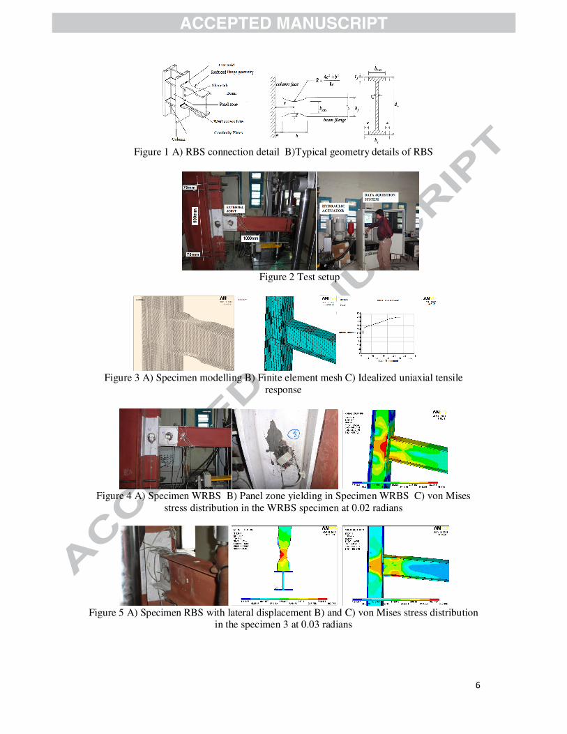
The RBS (Figure 1) connection is one of the most popular and most economical type amongst post Northridge (1994) and Kobe (1995) connections. Number of analytical and
experimental studies have been performed on RBS moment connection to examine: flange cut reduction geometry, beam web to column flange connection detail, behavior of panel
zone, requirement of continuity plate, lateral and local instability of beam, effect of
composite slab, and usefulness for retrofitting…etc. Further, prequalified RBS connection
details and guidelines are described in FEMA (Federal Emergency Management Academy)
350-351,355-D [1-3 ] and ANSI/AISC (American Institute of Steel Construction) 341-10 [4],
ANSI/AISC 358-10[5], ANSI/AISC 360-10 [6], National Institute of standards and
Technology-NEHRP Seismic Design Technical Brief No. 2 [7], EC8, Part 3[8] AISC Steel
design guide series -13 [9], NIST GCR 11-917-13[10] and PEER/ATC 72-1[11].
According to, Indian Standard (IS), IS 12778-2004 and IS 12779-1989 [12,13], hot rolled
parallel flange I beam sections are classified into 3 types namely as narrow parallel flange
beams (NPB), wide parallel flange beams (WPB) and parallel flange bearing pile sections
(PBP). Although, Parametric analysis by R. Goswami et al.[14] has shown that Indian hot
rolled I sections having yield stress 250 MPa do not meet compactness requirements
specified in Indian standards as well as of those countries with advanced seismic provision
for frames used in high seismic zones. However, hot rolled I beam sections having yield stress 250 MPa are most commonly available and used for steel structures in India. As RBS
connection is studied and used widely in US, Japan and Europe, however its study is quite limited with respect to Indian profiles and so not found mentioned in any Indian Standards
for steel design IS800-2007, IS808-1989, IS1852-1985, IS 2062-1999, IS8500-1991, IS12778-2004 & IS12779-1989, [15-19,12,13] It can be adopted in India for better
performance in strong and intermediate earthquakes [20].Considering the advantages of RBS moment connections and lack of knowledge of the performance of this connection with
2
respect to Indian profiles led to a study on this topic. The objective of this study was to
investigate experimentally the cyclic behaviour of welded moment connections with and
without RBS. Two external joint specimens were tested to compare and observe connection
behavior. Nonlinear finite element analysis of the connection models performed using the
computer program, ANSYS/Multiphysics.
Design of specimen Sections with 250MPa grade were considered for this study. Two specimens were studied,
designated as, connection without RBS as ‘WRBS’ and with RBS as ‘RBS’. RBS connection was designed based on specifications given as per AISC and FEMA codes. For panel zone as
well as continuity plates, design shear strength, required shear strength & column web/flange thickness limits were studied. The connection was representing an exterior strong-axis
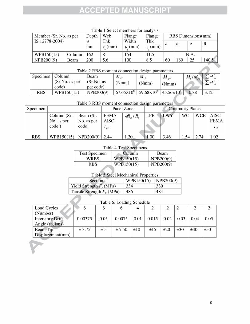
connection. Height of the column considered was 975mm and length of the beam from the centre of the column was 1000mm. Other, geometrical details are mentioned in Table 1.
Table 2 shows the strength of the connection calculated according to AISC/ FEMA formulae.
The ybyf
FZRM / ratio was within the limit (0.85 to 1) suggested by Engelhardt et al. [21].
Table 3 shows normalized limit states for CP and PZ.
From normalized values (>1) (Table 3) it can be observed that doubler plates as well as
continuity plates are not required. Therefore, RBS moment connection without doubler plates and continuity plates was considered for the study.
Experimental Study
Specimens were fabricated at Focus Robotomation Ltd. Pune, India and experimental procedure was carried out at Composite Research Centre labs at R&D Engineers, Pune, India.
Physical observation of members showed that, geometrical sizes and weights were as recommended by with Indian Standards IS 808-1989[16] and IS12778-2004[12]. The
sizes/weights of the members considered to model the exterior connection are listed in Table
4. Coupon testing was performed for steel shapes to establish the mechanical properties at
Perfect Laboratory Service, Pune, India (see Table 5).
Each beam flange and web was welded at the face of the column using fillet welds. It should
be noted that there were no web access holes. The welds' throats were 8 mm for all the
specimens. Welds' throat and quality were checked during fabrication. Test setup shown in
Figure 2, consisted of: Supporting frame, Test specimen (external subassemblage, Hydraulic
actuator (force rating ±100kN and stroke length ±125 mm), Data acquisition system and
strain gauges YFLA-5 of gauge resistance120Ω. For the test specimens cyclic loads (Table 6)
were applied to the tip of the beam following standard SAC loading history Clark et al.[22].
Finite Element Study The ANSYS Multiphysics [23] finite element software was used to model the specimens for
nonlinear analysis. An element SOLID45 from ANSYS element library was used for the 3-D finite element modelling of the RBS moment connection (Figure 3A, B). The fundamental
assumptions made to idealize steel mechanical properties are including: Young’s modulus of 2×10⁵ MPa, Poisson’s ratio of 0.3. Multi-linear stress strain curve are input directly as
element material property for cyclic analyses (Figure 3C). The column was assumed as pin connected at both the ends and at the joint beam to column element connection is configured
as fully restrained. Each subassembly is loaded at the beam free end in the displacement
control as per details given in above section of experimental study.
3
Performance of the Specimens
Observations of Specimen without Reduced Beam Section ‘WRBS’:
For, specimen WRBS (Figure 4A) column flange buckling was observed and it became more
pronounced with each successive loading cycle. From the flaking of the white wash in
column panel zone it was observed that column panel zone yielding above elastic limit had
occurred in this area (Figure 4B). During the first cycle of the 0.02 radians a crack was
developed near weld metal of beam bottom flange, no beam buckling was observed. Figure 4C shows von Mises stress diagram of the specimen. The von Mises contours shown Figure
4C indicate the highest regions of stress contours (435 - 485MPa) occur in panel zone as well in the vicinity of weld element. Reasonable correlation was observed between analysis and
experiment for all specimens.
Observations of Specimen with Reduced Beam Section ‘RBS’: The column panel zone stayed in the upper envelop of elastic state for the specimen as the
white wash stayed intact. Column flange or web buckling was not observed. No sign of
failure of from welding was observed during the test (Figure 5A, B, C). The von Mises
contours shown in Figure 5B & 5C indicate the highest regions of stress contours (358 - 403
MPa) occur in reduced beam section of the beam. This is approximately the upper envelop of
an inelastic state. RBS connection reached total interstory drift angle of 0.03 radians, which
exceeds the FEMA and AISC requirements for intermediate moment frame of 0.02 radians. Lateral displacement 21mm was observed during cycles of 0.03 radians (Figure 5A, 5B)
Hysteretic Behaviour:
The force-displacement hysteretic responses of the connections resulting from the experimental study are compared with those of the finite element analysis (Figure 6A and
6B). Reasonable correlation between the analysis and experimental results was observed.
With cyclic displacement increasing, both specimen share the almost same shape and curve
slope decreases continuously until attain the extreme limit loading. It showed that the
structures remain elastic before yielding. The area of hysteretic loops gradually increased and
residual deformations were observed with the increase of displacement after yielding.
Inelastic deformation occurred mainly in RBS area for connection ‘RBS’ creating ductile
fuse, whereas as it occurred in panel zone and beam flanges for connection ‘WRBS’
Conclusions
Both the experimental and numerical results observed that cyclic performance of the RBS
moment connection was much superior to the connection without RBS. No weld fracture was
observed in RBS connection while there was a crack observed near beam bottom flange weld
for connection without RBS. A reduction in material and labour cost is possible due to
elimination of continuity/doubler plates for RBS moment connection. Numbers of tests
conducted in above study are quite limited and more extensive testing is recommended to
understand behaviour of RBS for Indian profiles.
Acknowledgements
Funding for this research was provided by the Jindal Steel and Power Limited and Minor
Research Project, of Gujarat Council on Science and Technology, Department of Science and
Technology, Government of Gujarat. The writers would like to thank research laboratories,
Focus Robotomation Ltd., CRC labs at R&D Engineers, Perfect Laboratory, Pune.
4
References
[1] FEMA-350, Recommended Seismic Design Criteria for New Steel Moment Frame
Buildings, Federal Emergency Management Agency, Washington DC, USA, 2000.
[2] FEMA-351, Recommended Seismic Evaluation and Upgrade Criteria for Existing Welded
Steel Moment Frame Buildings, Federal Emergency Management Agency, Washington DC,
USA, 2000.
[3] FEMA-355D, State of the Art Report on Connection Performance, Federal Emergency Management Agency, Washington DC, USA, 2000.
[4] ANSI/AISC 341-10, Seismic provisions for Structural Steel Buildings, American Institute of Steel Construction, USA, 2010.
[5] ANSI/AISC 358-10, Prequalified Connections for Special and Intermediate Steel Moment Frames for Seismic Applications – Including Supplement No. 1, American Institute of Steel
Construction, USA, 2010. [6] ANSI/AISC 360-10, Specification for Structural Steel Buildings, American Institute of
Steel Construction, USA 2010.
[7] NEHRP Seismic Design Technical Brief No. 2 , Seismic Design of Steel Special Moment
Frame- A Guide for Practicing Engineers, USA, 2009.
[8] EC 8. Part 3, EN 1998-3, Design of Structures for Earthquake Resistance- Assessment
and Retrofitting of Buildings, UK, 2005. [9] AISC Steel Design Guide Series -13, Stiffenening of Wide-Flange Columns at Moment
Connections: Wind and Seismic Applications, American Institute of Steel Construction, USA, 1999.
[10] NIST GCR 11-917-13, Research Plan For The Study Of Seismic Behaviour and Design
of Deep, Slender Wide Flange Structural Steel Beam-Column Members, NIST, USA, 2011.
[11] PEER/ATC 72-1, Modelling and Acceptance Criteria for Seismic Design And Analysis
Of Tall Buildings, Applied Technology Council, Pacific Earthquake Engineering Research
Center (Peer), USA, 2010. [12] Bureau of Indian Standards, IS 12778, Hot Rolled Parallel Flange Steel Sections for
Beams, Columns and Bearing Piles- Dimensions and Section Properties, India, 2004. [13] Bureau of Indian Standards, IS 12779, Rolling and Cutting Tolerences for Hot Rolled
Parallel Flange Beams and Columns Section – Specifications, 1989. [14] R.Goswami, J.N.Arlekar, CVR.Murthy, Limitations of available Indian hot-rolled I-
sections for use in seismic steel MRFs, Report nicee, IIT Kanpur. 2006. [15] Bureau of Indian Standards IS 800, General Construction in Steel- Code of Practice,
2007.
[16] Bureau of Indian Standards IS 808, Dimensions for Hot Rolled Steel Beam, Column,
Channel and Angle Sections, 1989.
[17] Bureau of Indian Standards, IS 1852, Specification for Rolling and Cutting Tolerances
for Hot-Rolled Steel Products, 1985.
[18] Bureau of Indian Standards, IS 2062, Steel for General Structural Purposes-
Specification. 1999.
[19] Bureau of Indian Standards, IS 8500, Structural Steel - Micro Alloyed (Medium and
High Strength Qualities) Specifications, 1991.
[20] N. Subramanian, Pre-qualified seismic moment connection, NBMCW, 16 (2010) 160-
171.
[21] M. D. Engelhardt, T.Winneberger, A. J. Zekany, and T. J. Potyraj, Experimental
investigations of dogbone moment connections, Engg Journal, AISC, 35( 1998) 128–139. [22] P. Clark, K. Frank, H. Krawinkler, and R. Shaw, Protocol for Fabrication, Inspection,
Testing, and Documentation of Beam-Column Connection Tests and Other Experimental Specimens, Report No. SAC/BD-97/02, SAC Joint Venture, Sacramento, CA. 1997
5
[23] ANSYS / Multiphysics (Release 11), ANSYS, Inc., Southpointe 275 Technology Drive,
Canonsburg, PA.
6
Figure 1 A) RBS connection detail B)Typical geometry details of RBS
Figure 2 Test setup
Figure 3 A) Specimen modelling B) Finite element mesh C) Idealized uniaxial tensile
response
Figure 4 A) Specimen WRBS B) Panel zone yielding in Specimen WRBS C) von Mises
stress distribution in the WRBS specimen at 0.02 radians
Figure 5 A) Specimen RBS with lateral displacement B) and C) von Mises stress distribution
in the specimen 3 at 0.03 radians

7
Figure 6 A) Force-displacement response of specimen ‘WRBS’ B) Force-displacement
response of specimen ‘RBS’
8
Table 1 Select members for analysis
Member (Sr. No. as per IS 12778-2004)
Depth
d
mm
Web Thk
wt (mm)
Flange Width
fb (mm)
Flange Thk
ft (mm)
RBS Dimensions(mm)
a
b
c R
WPB150(15) Column 162 8 154 11.5 N.A.
NPB200 (9) Beam 200 5.6 100 8.5 60 160 25 140.5
Table 2 RBS moment connection design parameters
Specimen Column
(Sr.No. as per
code)
Beam
(Sr.No. as
per code)
peM
(Nmm)
fM
(Nmm) prM
(Nmm)
Pef MM /
∑
∑*
*
pb
pc
M
M
RBS WPB150(15) NPB200(9) 67.65×10⁶ 59.68×10
6 45.56×10
6 0.88 3.12
Table 3 RBS moment connection design parameters
Specimen Panel Zone Continuity Plates
Column (Sr.
No. as per
code )
Beam (Sr.
No. as per
code)
FEMA
AISC
pzt
un RR /φ
LFB
LWY
WC
WCB
AISC
FEMA
cft
RBS WPB150(15) NPB200(9) 2.44 1.20 1.00 3.46 1.54 2.74 1.02
Table 4 Test Specimens
Test Specimen Column Beam
WRBS WPB150(15) NPB200(9)
RBS WPB150(15) NPB200(9)
Table 5 Steel Mechanical Properties
Section WPB150(15) NPB200(9)
Yield Strength Fy (MPa) 334 330
Tensile Strength Fu (MPa) 486 484
Table 6. Loading Schedule
Load Cycles (Number)
6 6 6 4 2 2 2 2 2
Interstory Drift Angle (radians)
0.00375 0.05 0.0075 0.01 0.015 0.02 0.03 0.04 0.05
Beam Tip Displacement(mm)
± 3.75 ± 5 ± 7.50 ±10 ±15 ±20 ±30 ±40 ±50
Related Documents