UNCORRECTED PROOF 3 Study of moisture in buildings for hot humid climates 4 Franck Lucas *,1 , Laetitia Adelard 1 , Franc ¸ois Garde 1 , Harry Boyer 1 5 Laboratoire de Ge ´nie Industriel, IUT de Saint Pierre, Universite ´ of Reunion Island, 40 avenue de Soweto, 6 Saint-Pierre, Reunion Island, 97 410, France 7 Received 5 June 2001; accepted 15 August 2001 8 9 Abstract 10 11 Humidity in buildings generates many disorders or disadvantages. A dry-bulb temperature of the air relatively low, strong moisture and 12 wall surface temperatures very low characterize the interior conditions of the highland dwellings in Reunion Island, during the southern 13 winter. This causes many disorders related to phenomena of condensation on walls: deterioration of the envelope, odor of mould. It is thus, 14 significant to precisely know the evolution of the moisture in a building to avoid any disorder on the frame. In this study we will expose a 15 series of experiments carried out on real residences in order to highlight main parameters of the problem. On the basis of these results, 16 numerical simulations were used to extrapolate the behavior of this building on unusual climatic sequences, holding account various 17 improvements of its constitution. A curative study and a preventive study were carried out on two different types of residences. The aim is 18 to propose solutions to prevent deteriorations of the coatings due to the surface condensation. # 2001 Published by Elsevier Science B.V. 19 20 Keywords: Humidity; Condensation; Expe ´rimentations; Numerical simulations; Humid climate 21 22 1. Introduction 23 In moderate climate, hydrous transfers in buildings are 24 relatively well controlled as they are generally in a well- 25 defined direction. Indeed, interior climatic conditions are 26 controlled by air-conditioning systems, which ensure a 27 constant temperature. In certain cases, humidity is also 28 controlled precisely In wet tropical climate a majority of 29 residences is not air-conditioned and the interior tempera- 30 ture and humidity are free floating. Moreover, in the high- 31 lands of Reunion Island, the dry-bulb temperature of the air 32 decreases appreciably with altitude to go down below the 33 usual values of comfort. Low dry-bulb temperature of air, 34 strong moisture and wall surface temperatures very low 35 characterize the interior conditions of the highland dwell- 36 ings, during the southern winter. Taking into account the 37 external conditions the transferred moisture quantities are 38 significant. It follows of many disorders related to phenom- 39 ena of condensation on wall. The buildings’ owners con- 40 fronted with these problems have significant maintenance 41 and restoration costs, and must work out preventive and 42 curative solutions. They then initiated this study and the 43 carried out reflection takes into account the economic con- 44 straints they are confronted with. This paper proposes to 45 present the methodology used and the results obtained. After 46 a reviewing concerning moisture in buildings, we will 47 present the study undertaken in order to cure the problems 48 on existing dwellings. This first study is composed of a series 49 of measurements carried out to examine buildings having 50 undergone degradations with an aim of identifying the 51 causes of the damages. We will then present the tools used 52 for simulations and the results, which validate some 53 improvements concerning the thermal design of the envel- 54 ope and the associated systems, in order to cure the pro- 55 blems. In the third part, we will present the study carried out 56 for a building project with a timber structure and therefore 57 with preventive purposes. 58 2. Outline relating to humidity in buildings 59 Humidity in dwellings has consequences not only on the 60 comfort and health of occupants but also on perenniality of 61 the coatings and the frame. Condensation of water con- 62 tained in air occurs when the relative humidity reached a 63 limiting value known as saturation. Condensation can 64 appear in the form of droplets in suspension in air (fog) 65 or on a cold material support. The presence of fog in a Energy and Buildings 1382 (2001) 1–11 * Corresponding author. Tel.: þ33-2-62-96-28-94; fax: þ33-2-62-96-28-99. E-mail address: [email protected] (F. Lucas). 1 Tel.: þ33-2-62-96-28-91; fax: þ33-2-62-96-28-99. 1 0378-7788/01/$ – see front matter # 2001 Published by Elsevier Science B.V. 2 PII:S0378-7788(01)00115-3

Welcome message from author
This document is posted to help you gain knowledge. Please leave a comment to let me know what you think about it! Share it to your friends and learn new things together.
Transcript
UN
CO
RR
ECTE
D P
RO
OF
3 Study of moisture in buildings for hot humid climates
4 Franck Lucas*,1, Laetitia Adelard1, Francois Garde1, Harry Boyer1
5 Laboratoire de Genie Industriel, IUT de Saint Pierre, Universite of Reunion Island, 40 avenue de Soweto,
6 Saint-Pierre, Reunion Island, 97 410, France
7 Received 5 June 2001; accepted 15 August 2001
8
9 Abstract
10
11 Humidity in buildings generates many disorders or disadvantages. A dry-bulb temperature of the air relatively low, strong moisture and
12 wall surface temperatures very low characterize the interior conditions of the highland dwellings in Reunion Island, during the southern
13 winter. This causes many disorders related to phenomena of condensation on walls: deterioration of the envelope, odor of mould. It is thus,
14 significant to precisely know the evolution of the moisture in a building to avoid any disorder on the frame. In this study we will expose a
15 series of experiments carried out on real residences in order to highlight main parameters of the problem. On the basis of these results,
16 numerical simulations were used to extrapolate the behavior of this building on unusual climatic sequences, holding account various
17 improvements of its constitution. A curative study and a preventive study were carried out on two different types of residences. The aim is
18 to propose solutions to prevent deteriorations of the coatings due to the surface condensation. # 2001 Published by Elsevier Science B.V.1920 Keywords: Humidity; Condensation; Experimentations; Numerical simulations; Humid climate21
22 1. Introduction
23 In moderate climate, hydrous transfers in buildings are
24 relatively well controlled as they are generally in a well-
25 defined direction. Indeed, interior climatic conditions are
26 controlled by air-conditioning systems, which ensure a
27 constant temperature. In certain cases, humidity is also
28 controlled precisely In wet tropical climate a majority of
29 residences is not air-conditioned and the interior tempera-
30 ture and humidity are free floating. Moreover, in the high-
31 lands of Reunion Island, the dry-bulb temperature of the air
32 decreases appreciably with altitude to go down below the
33 usual values of comfort. Low dry-bulb temperature of air,
34 strong moisture and wall surface temperatures very low
35 characterize the interior conditions of the highland dwell-
36 ings, during the southern winter. Taking into account the
37 external conditions the transferred moisture quantities are
38 significant. It follows of many disorders related to phenom-
39 ena of condensation on wall. The buildings’ owners con-
40 fronted with these problems have significant maintenance
41 and restoration costs, and must work out preventive and
42curative solutions. They then initiated this study and the
43carried out reflection takes into account the economic con-
44straints they are confronted with. This paper proposes to
45present the methodology used and the results obtained. After
46a reviewing concerning moisture in buildings, we will
47present the study undertaken in order to cure the problems
48on existing dwellings. This first study is composed of a series
49of measurements carried out to examine buildings having
50undergone degradations with an aim of identifying the
51causes of the damages. We will then present the tools used
52for simulations and the results, which validate some
53improvements concerning the thermal design of the envel-
54ope and the associated systems, in order to cure the pro-
55blems. In the third part, we will present the study carried out
56for a building project with a timber structure and therefore
57with preventive purposes.
582. Outline relating to humidity in buildings
59Humidity in dwellings has consequences not only on the
60comfort and health of occupants but also on perenniality of
61the coatings and the frame. Condensation of water con-
62tained in air occurs when the relative humidity reached a
63limiting value known as saturation. Condensation can
64appear in the form of droplets in suspension in air (fog)
65or on a cold material support. The presence of fog in a
Energy and Buildings 1382 (2001) 1–11
* Corresponding author. Tel.: þ33-2-62-96-28-94;
fax: þ33-2-62-96-28-99.
E-mail address: [email protected] (F. Lucas).1 Tel.: þ33-2-62-96-28-91; fax: þ33-2-62-96-28-99.
1 0378-7788/01/$ – see front matter # 2001 Published by Elsevier Science B.V.
2 PII: S 0 3 7 8 - 7 7 8 8 ( 0 1 ) 0 0 1 1 5 - 3
UN
CO
RR
ECTE
D P
RO
OF
66 dwelling is rare. It is generally confined in specific parts and
67 over short periods related to the occupant activity. Natural
68 or mechanical ventilations are intended to fight efficiently
69 against these internal contributions. Condensation on a
70 material support occurs when the temperature of this one
71 is lower than the air dew point temperature of the zone. This
72 case worries the designers by the degradations involved on
73 the support. The caused disorders are generally deteriora-
74 tions of the interior coatings (yellowish, black spots and
75 then separation of paintings). Phenomena of corrosion of
76 the metal structure can appear in the event of cracks in the
77 coating. The hydrous transfers depend on the following
78 phenomena:
� Diffusion of water vapor through the envelope of the
81 room;
� Surface condensation of the water vapor;
� Absorption and water vapor desorption by hygroscopic
84 materials of the room;
� Airflow transfers with the outside or the other zones of the
86 building;
� Diffusion of vapor in the air;
� Production of vapor dependent on occupants and their
89 activities;
� Injection or withdrawal of moisture by HVAC system.91
92 2.1. The water vapor diffusion through a wall
93 This depends on the difference of partial pressure of vapor
94 on both sides of the wall and the permeability of material
95 following the law
jvdif¼ �p
dPv
dx(1)
9798This equation imposes a good knowledge of the material
99properties constitutive of the wall and applies badly to
100heterogeneous or strongly hygroscopic materials. Several
101methods of wall design are based on this equation: Dew-
102point method, Glaser diagram. Their objective is to evaluate
103the possibility of condensation of the water vapor during its
104migration through the wall. These methods are intended for
105the study of the wall in steady state conditions. In moderate
106climates, as the building are more often heated, the migra-
107tion of vapor is from outside to inside. In tropical climate,
108most of the time, outside and inside conditions vary without
109any control and consequently, the direction of the vapor flow
110is not so well defined as the experiment will show it.
111Moreover, the steady state methods do not consider the
112cycles of condensation/evaporation. It is then difficult to
113evaluate generated damages, knowing that a small quantity
114of condensation remains tolerable. In the simulation codes,
115the term of water vapor diffusion through the envelope is
116often neglected in the hydrous balance of a zone. Its
117influence is indeed weak comparison with the quantities
118exchanged through openings or by ventilation.
1192.2. Surface condensation
120It happens when the temperature of a wall is lower than
121the dew point temperature, we have
_mvcond ¼ Sjcond (2)123
124The rate of vapor condensation depends on the difference in
125partial pressure of vapor between the air of the room and the
126air on the surface of the wall and can be expressed by [1]
jcond ¼ $ðPvair � Pvsurf Þ ¼ $ðPvair � Pvsurf; satÞ;$ ¼ 7:4� 10�9hc (3)
128
129where, for walls
hc ¼ 1:079DT0:33 and for tilted roofs; hc ¼ 1:135DT0:33
(4)131
132with [2]
Pvair ¼H
100Pvair; sat
Pvair; sat ¼ 140974 � 105 exp�3928:5
Tair þ 231:667
� �(5)
134
Pvsat; surf ¼ f ðTsurfÞ ¼ 140974� 105 exp�3928:5
Tsurf þ 231:667
� �
(6)136
1372.3. The hygroscopic behavior of materials
138The hygroscopic behavior of materials is not always taken
139into account in building thermal simulations. However, it
140constitutes in certain case a significant element of moisture
141exchanges in a room.One candistinguish two typesofmodels,
Nomenclature
j mass flow rate (kg/m2 s)
_m mass flow (kg/s)
p permeability (kg/m Pa s)
H relative humidity (%)
P pressure (Pa)
x distance (m)
T temperature (k)
w humidity ratio (kg/kgdryair)
h exchange coefficient (W/Km2)
Subscript
v vapour
air air in the zone
ae outside air
as dry air
surf surface
sat saturation
c convection
i subscript of the zones
2 F. Lucas et al. / Energy and Buildings 1382 (2001) 1–11
UN
CO
RR
ECTE
D P
RO
OF� the detailed models, based on the diffusion law of the
143 water vapor through the walls of the envelope and in
144 materials of the room. These models require a perfect
145 knowledge of the building constitution and the character-
146 istics of the materials used. This data are often difficult to
147 evaluate in the project phases as well as for the existing
148 buildings.
� the simplified models simulate the behavior of a fictive
150 volume representing materials of the room reacting with
151 the moisture of the air. This fictive volume called buffer,
152 generally consists of two parts: a surface element reacting
153 with the moisture of the zone and a heart exchanging with
154 the surface element. The buffer is characterized by a
155 reduced number of coefficient. They are evaluated either
156 summarily by qualifying more or less the behavior of the
157 hygroscopic room [3] or, more precisely, by giving a
158 description of the materials of the room and their proper-
159 ties [4]. Another type of models consists in defining two
160 buffers one reacting quickly with the moisture of the air
161 and the other slowly [5].162
163 For the curative study, we studied uninhabited residences
164 consisting of little hygroscopic materials (metal roof and
165 wall in coated breeze blocks) so, we will not consider the
166 phenomena of absorption or desorption due to hygroscopic
167 materials. On the other hand, for the preventive study, the
168 structure of buildings being made of timber we chose to
169 carry out simulations using TYPE 56 of TRNSYS [4]. This
170 multi-zone building model includes a hygroscopic buffer
171 model.
172 2.4. The airflow transfers
173 The air transfers with outside or with the other zones
174 intervene in the moisture balance of the zone in the form
_mvaeraul ¼ _masðwae � wiÞ (7)176
177 2.5. The vapor diffusion in the air
178 It is generally neglected compared to the quantities
179 exchanged by airflow transfers.
180 2.6. Contributions due to the occupants
181 The releases of vapor due to occupants and their activity
182 are significant and can reach up to 20 l of water per day for a
183 family of four people. This load appears in the moisture
184 balance of the zone in a term giving the vapor generation
185 rate.
186 2.7. Contributions due to air conditioning systems
187 The most common type of HVAC system used in Reunion
188 are split-system functioning with 100% of recycled air. The
189 moisture exchanges due to HVAC are evaluated according to
190 the evolution of the air on the exchanger.
191The heating of air is done with constant absolute humidity
192and does not modify the moisture balance of the zone. The
193split-systems used carry out a cooling, with generally a
194dehumidification of the air through the cold battery. The
195quantity of condensates extracted from the zone will then be
196determined by
_mvSTA ¼ _maseðwb � wiÞwith e ¼ wi � we
wi � wb
¼ Ti � Te
Ti � Tb(8)
198
1993. Curative study
2003.1. Introduction
201This work is intended to study the problem of condensa-
202tion on existing buildings. A series of measurements was
203carried out to highlight the various sites of surface con-
204densation, the process of condensation and the repercussions
205concerning the users of the dwellings. This phase will have
206to validate some assumptions required for mathematical
207modelling. Instrumentation was thus, carried out on empty
208dwellings. Moreover, users were interviewed in order to
209determine their behaviors and their reaction to the problems
210encountered. This study will lead to prescriptions and
211evaluation of improvements, which can be applied to exist-
212ing residences.
2133.2. Series of measurements
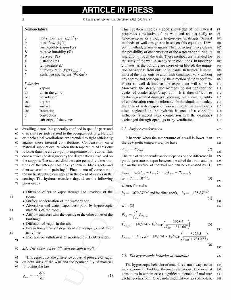
2143.2.1. The buildings under study
215The study relates to two groups of dwellings located in the
216highlands of Reunion Island at ‘‘L’Entre-Deux’’ (400 m of
217altitude) and ‘‘Le Tampon’’ (800 m) (see Fig. 1). The studied
218residences do not comprise heating or cooling system. The
219majority of the instrumented residences are uninhabited and
220not furnished. The studied rooms are isolated from other
221rooms of the dwelling by closing the gates of communica-
222tion. The walls are in hollow blocks of 20 cm covered with
223painted coating mortar outside and inside. The roof consists
224of a ceiling in plasterboards of 1.2 cm, a air layer, glass wool
225insulator for the building in ‘‘l’Entre-Deux’’ (no insulation
226for the building in ‘‘Le Tampon’’) and a corrugated iron.
227The experimental campaign was conducted during the
228end of the coldest period of the year corresponding to the
229southern winter. The two sites are characterized by different
230climatic conditions. ‘‘Le Tampon’’ is generally colder and
231wetter than the site of ‘‘l’Entre-Deux’’. The average tem-
232perature and relative humidity are given in Table 1.
233The most damaged rooms of the buildings were instru-
234mented in a precise way. The characteristics of the air of the
235rooms (dry-bulb temperature, resultant temperature, relative
236humidity) were noted down as well as the temperatures of
237surface of the walls, floor and ceiling. The main damages
238being located on the ceiling, we measured the characteristics
239of the air layer inside the ceiling and the surface tempera-
F. Lucas et al. / Energy and Buildings 1382 (2001) 1–11 3
UN
CO
RR
ECTE
D P
RO
OF
240 tures of the various parts of the frame. The complete
241 instrumentation requiring the drilling of the ceiling and
242 the installation of a heavy hardware, the living rooms and
243 the bathrooms of the inhabited residences were instrumented
244 in a reduced way by small autonomous sensors of air
245 temperature and relative humidity.
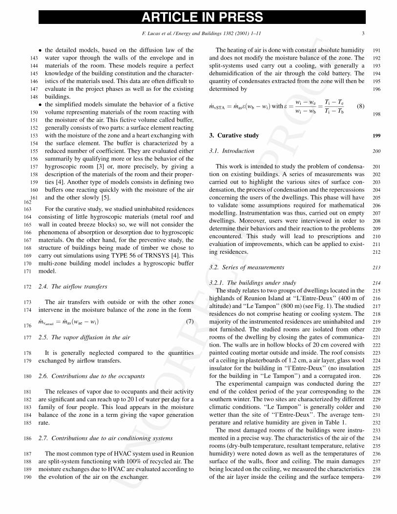
2463.2.2. Experimental results
247In Fig. 2, the sites of condensation are characterized by a
248negative difference between temperature of surface and dew
249point temperature of air. Condensation occurs at the coldest
250hours of the day. On the corrugated iron, condensation
251occurs almost throughout the night between 7:00 pm and
2528:00 am. It appears on steel structure very early in the
253morning when it is cooled by conduction with iron sheet
254and when the temperature of the surrounding air is mini-
255mum. Under certain colder climatic conditions, condensa-
256tion can appear on the higher face of plasterboard, on outside
257walls, and on the lower face of plasterboard (in absence of
258insulation in the roof). Let us note that the frontages exposed
259to the south and the west have more significant duration of
260condensation because they do not benefit quickly from the
261solar contributions.
Fig. 1. Buildings under study: Le Tampon and l’Entre-Deux.
Table 1
Climatic conditions of the two sites.
Mean Minimum Maximum
Le Tampon Temperature 19.9 12.1 25.4
Humidity 70.4 33.5 92.0
L’Entre-deux Temperature 19.2 12.3 27.5
Humidity 68.4 33.9 93.6
Fig. 2. Visualization of surface condensation in the roof.
4 F. Lucas et al. / Energy and Buildings 1382 (2001) 1–11
UN
CO
RR
ECTE
D P
RO
OF
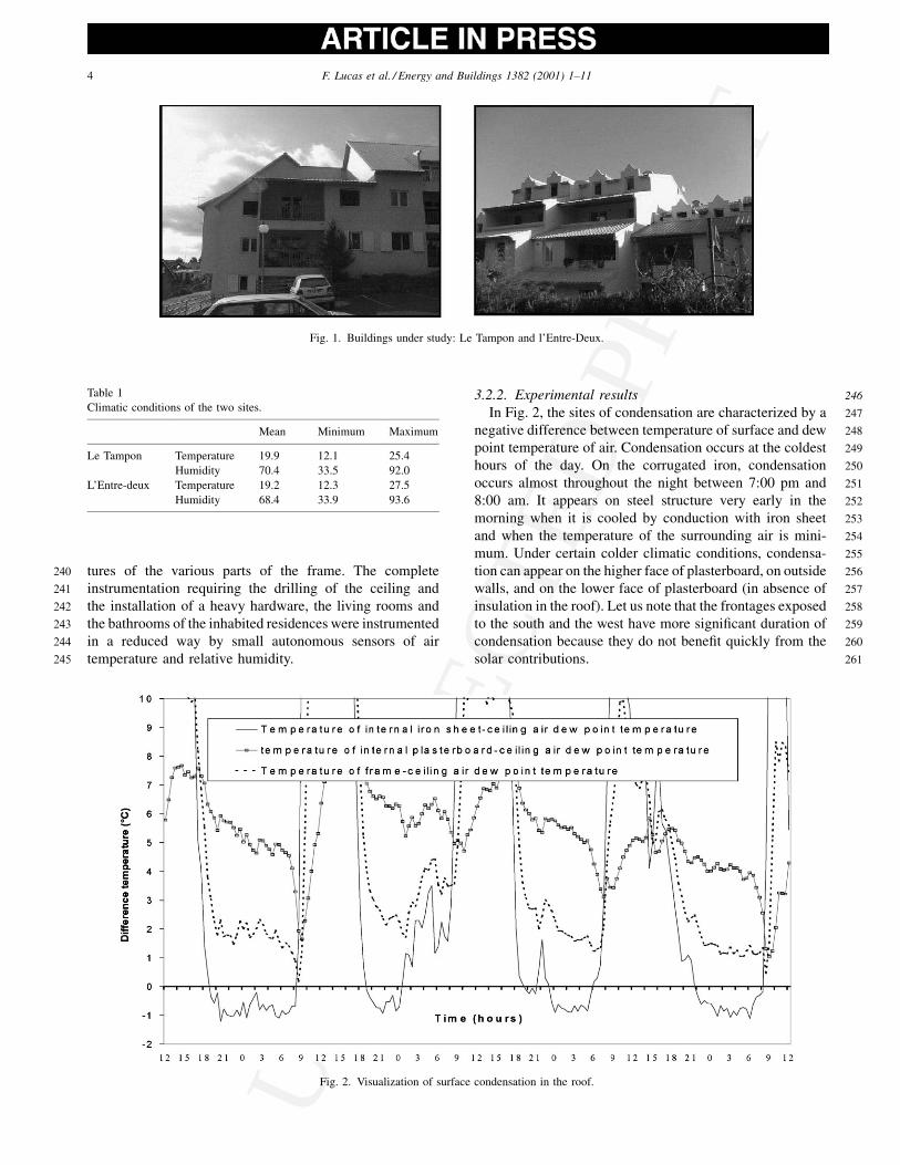
262 The principal sites of condensation are identified and pre-
263 sented in Fig. 3 by order of importance in the diagram below:
264 Fig. 4 shows the evolution of vapor pressure for the indoor
265 and the outdoor conditions. One can notice that the sign of
266vapor pressure gradient, between inside and outside,
267expressed in Eq. (1), is changing along the period. The
268diffusion of vapor is from outside to inside during the day
269and reverse at night. Anyway, the vapor pressure gradient is
270weak and thus, a very few quantity of vapor is transferred by
271diffusion. This can justify the assumption to neglect the
272vapor diffusion through walls used in simulation codes.
273Moreover, we can notice that the position of vapor barrier
274is consequently not well defined in this climate.
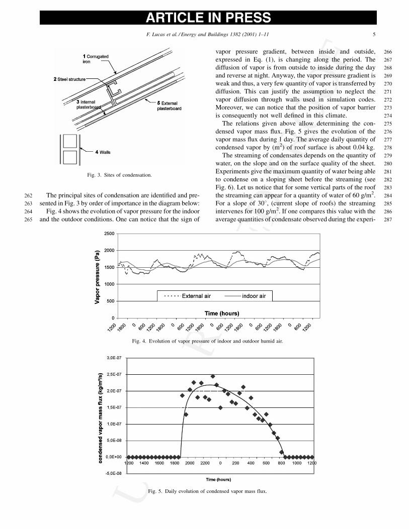
275The relations given above allow determining the con-
276densed vapor mass flux. Fig. 5 gives the evolution of the
277vapor mass flux during 1 day. The average daily quantity of
278condensed vapor by (m2) of roof surface is about 0.04 kg.
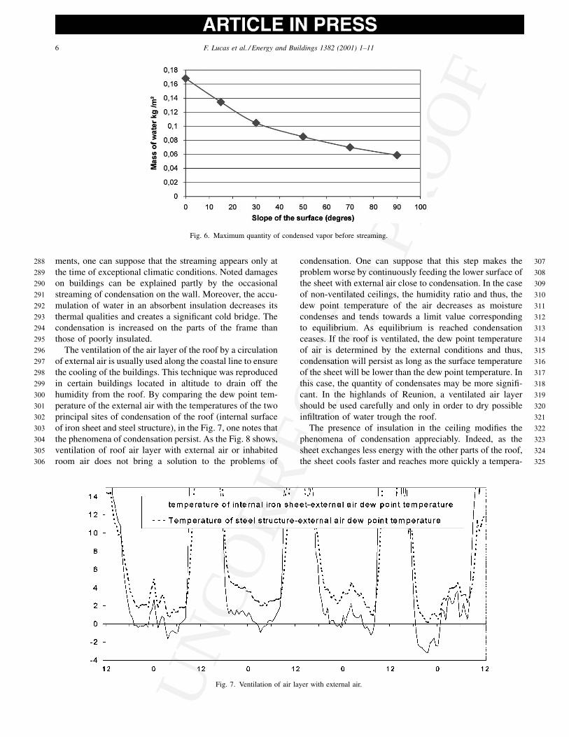
279The streaming of condensates depends on the quantity of
280water, on the slope and on the surface quality of the sheet.
281Experiments give the maximum quantity of water being able
282to condense on a sloping sheet before the streaming (see
283Fig. 6). Let us notice that for some vertical parts of the roof
284the streaming can appear for a quantity of water of 60 g/m2.
285For a slope of 308, (current slope of roofs) the streaming
286intervenes for 100 g/m2. If one compares this value with the
287average quantities of condensate observed during the experi-
Fig. 3. Sites of condensation.
Fig. 4. Evolution of vapor pressure of indoor and outdoor humid air.
Fig. 5. Daily evolution of condensed vapor mass flux.
F. Lucas et al. / Energy and Buildings 1382 (2001) 1–11 5
UN
CO
RR
ECTE
D P
RO
OF
288 ments, one can suppose that the streaming appears only at
289 the time of exceptional climatic conditions. Noted damages
290 on buildings can be explained partly by the occasional
291 streaming of condensation on the wall. Moreover, the accu-
292 mulation of water in an absorbent insulation decreases its
293 thermal qualities and creates a significant cold bridge. The
294 condensation is increased on the parts of the frame than
295 those of poorly insulated.
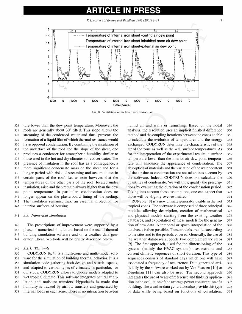
296 The ventilation of the air layer of the roof by a circulation
297 of external air is usually used along the coastal line to ensure
298 the cooling of the buildings. This technique was reproduced
299 in certain buildings located in altitude to drain off the
300 humidity from the roof. By comparing the dew point tem-
301 perature of the external air with the temperatures of the two
302 principal sites of condensation of the roof (internal surface
303 of iron sheet and steel structure), in the Fig. 7, one notes that
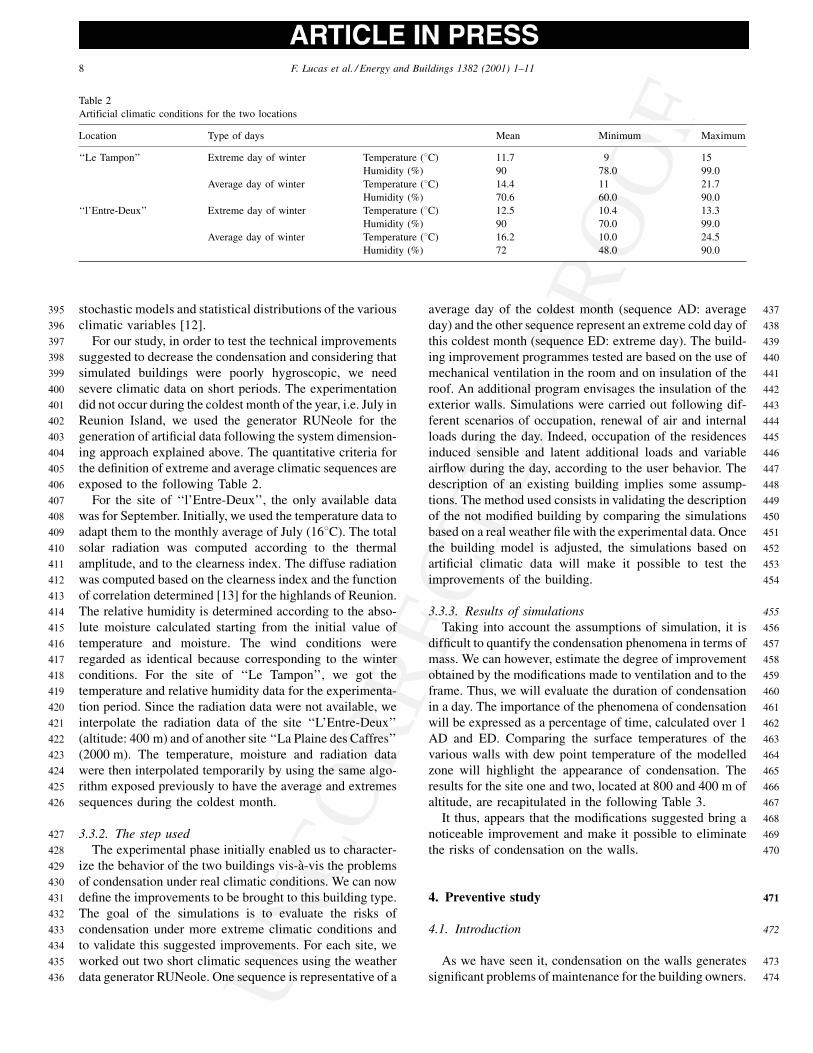
304 the phenomena of condensation persist. As the Fig. 8 shows,
305 ventilation of roof air layer with external air or inhabited
306 room air does not bring a solution to the problems of
307condensation. One can suppose that this step makes the
308problem worse by continuously feeding the lower surface of
309the sheet with external air close to condensation. In the case
310of non-ventilated ceilings, the humidity ratio and thus, the
311dew point temperature of the air decreases as moisture
312condenses and tends towards a limit value corresponding
313to equilibrium. As equilibrium is reached condensation
314ceases. If the roof is ventilated, the dew point temperature
315of air is determined by the external conditions and thus,
316condensation will persist as long as the surface temperature
317of the sheet will be lower than the dew point temperature. In
318this case, the quantity of condensates may be more signifi-
319cant. In the highlands of Reunion, a ventilated air layer
320should be used carefully and only in order to dry possible
321infiltration of water trough the roof.
322The presence of insulation in the ceiling modifies the
323phenomena of condensation appreciably. Indeed, as the
324sheet exchanges less energy with the other parts of the roof,
325the sheet cools faster and reaches more quickly a tempera-
Fig. 6. Maximum quantity of condensed vapor before streaming.
Fig. 7. Ventilation of air layer with external air.
6 F. Lucas et al. / Energy and Buildings 1382 (2001) 1–11
UN
CO
RR
ECTE
D P
RO
OF
326 ture lower than the dew point temperature. Moreover, the
327 roofs are generally about 308 tilted. This slope allows the
328 streaming of the condensed water and thus, prevents the
329 formation of a liquid film of which thermal resistance would
330 have opposed condensation. By combining the insulation of
331 the underface of the roof and the slope of the sheet, one
332 produces a condenser for atmospheric humidity similar to
333 those used in the hot and dry climates to recover water. The
334 presence of insulation in the roof has as a consequence, a
335 more significant condensate mass on the sheet and for a
336 longer period with risks of streaming and accumulation in
337 certain parts of the roof. Let us note however, that the
338 temperatures of the other parts of the roof, located under
339 insulation, raise and then remain always higher than the dew
340 point temperature. In particular, condensation does no
341 longer appear on the plasterboard lining of the ceiling.
342 The insulation remains, thus, an essential protection for
343 interior surfaces of housing.
344 3.3. Numerical simulation
345 The prescriptions of improvement were supported by a
346 phase of numerical simulations based on the use of thermal
347 building simulation software and on a weather data gen-
348 erator. These two tools will be briefly described below.
349 3.3.1. The tools
350 CODYRUN [6,7], is a multi-zone and multi-model soft-
351 ware for the simulation of building thermal behavior. It is a
352 simulation code gathering both design and search aspects,
353 and adapted to various types of climates. In particular, for
354 our study, CODYRUN allows to choose models adapted to
355 wet tropical climate. This software integrates natural venti-
356 lation and moisture transfers. Hypothesis is made that
357 humidity is tracked by airflow transfers and generated by
358 internal loads in each zone. There is no interaction between
359humid air and walls or furnishing. Based on the nodal
360analysis, the resolution uses an implicit finished difference
361method and the coupling iterations between the zones enable
362to calculate the evolution of temperatures and the energy
363exchanged. CODYRUN determine the characteristics of the
364air of the zone as well as the wall surface temperatures. As
365for the interpretation of the experimental results, a surface
366temperature lower than the interior air dew point tempera-
367ture will announce the appearance of condensation. The
368absorption of materials and the variation of the water content
369of the air due to condensation are not taken into account by
370the software. Indeed, CODYRUN does not calculate the
371quantities of condensate. We will thus, qualify the prescrip-
372tions by evaluating the duration of the condensation period.
373Taking into account these assumptions, one can expect that
374those will be slightly over-estimated.
375RUNeole [8] is a new climate generator usable in the wet
376tropical zones. The software is composed of three principal
377modules allowing description, creation of mathematical
378and physical models starting from the existing weather
379databases, and exploitation of these models for the genera-
380tion of new data. A temporal or space interpolation of the
381databases is then possible. These models are filed according
382to the sites and to the periods covered. Generally, the use of
383the weather databases supports two complementary steps
384[9]. The first approach, used for the dimensioning of the
385systems (mainly the HVAC systems) uses extreme and
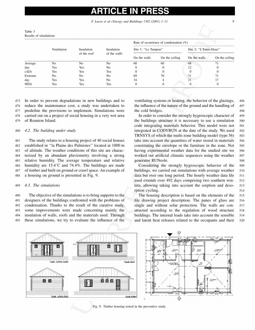
386current climatic sequences of short duration. This type of
387sequences consists of standard days which one will have
388associated a frequency of occurrence. Data generated arti-
389ficially by the software worked out by Van Paassen [10] or
390Degelman [11] can also be used. The second approach
391integrates the use of years of reference and finds its applica-
392tion in the evaluation of the average power consumption of a
393building. Theweather data generators also provide this type
394of data while being based on functions of correlation,
Fig. 8. Ventilation of air layer with various air.
F. Lucas et al. / Energy and Buildings 1382 (2001) 1–11 7
UN
CO
RR
ECTE
D P
RO
OF
395 stochastic models and statistical distributions of the various
396 climatic variables [12].
397 For our study, in order to test the technical improvements
398 suggested to decrease the condensation and considering that
399 simulated buildings were poorly hygroscopic, we need
400 severe climatic data on short periods. The experimentation
401 did not occur during the coldest month of the year, i.e. July in
402 Reunion Island, we used the generator RUNeole for the
403 generation of artificial data following the system dimension-
404 ing approach explained above. The quantitative criteria for
405 the definition of extreme and average climatic sequences are
406 exposed to the following Table 2.
407 For the site of ‘‘l’Entre-Deux’’, the only available data
408 was for September. Initially, we used the temperature data to
409 adapt them to the monthly average of July (168C). The total410 solar radiation was computed according to the thermal
411 amplitude, and to the clearness index. The diffuse radiation
412 was computed based on the clearness index and the function
413 of correlation determined [13] for the highlands of Reunion.
414 The relative humidity is determined according to the abso-
415 lute moisture calculated starting from the initial value of
416 temperature and moisture. The wind conditions were
417 regarded as identical because corresponding to the winter
418 conditions. For the site of ‘‘Le Tampon’’, we got the
419 temperature and relative humidity data for the experimenta-
420 tion period. Since the radiation data were not available, we
421 interpolate the radiation data of the site ‘‘L’Entre-Deux’’
422 (altitude: 400 m) and of another site ‘‘La Plaine des Caffres’’
423 (2000 m). The temperature, moisture and radiation data
424 were then interpolated temporarily by using the same algo-
425 rithm exposed previously to have the average and extremes
426 sequences during the coldest month.
427 3.3.2. The step used
428 The experimental phase initially enabled us to character-
429 ize the behavior of the two buildings vis-a-vis the problems
430 of condensation under real climatic conditions. We can now
431 define the improvements to be brought to this building type.
432 The goal of the simulations is to evaluate the risks of
433 condensation under more extreme climatic conditions and
434 to validate this suggested improvements. For each site, we
435 worked out two short climatic sequences using the weather
436 data generator RUNeole. One sequence is representative of a
437average day of the coldest month (sequence AD: average
438day) and the other sequence represent an extreme cold day of
439this coldest month (sequence ED: extreme day). The build-
440ing improvement programmes tested are based on the use of
441mechanical ventilation in the room and on insulation of the
442roof. An additional program envisages the insulation of the
443exterior walls. Simulations were carried out following dif-
444ferent scenarios of occupation, renewal of air and internal
445loads during the day. Indeed, occupation of the residences
446induced sensible and latent additional loads and variable
447airflow during the day, according to the user behavior. The
448description of an existing building implies some assump-
449tions. The method used consists in validating the description
450of the not modified building by comparing the simulations
451based on a real weather file with the experimental data. Once
452the building model is adjusted, the simulations based on
453artificial climatic data will make it possible to test the
454improvements of the building.
4553.3.3. Results of simulations
456Taking into account the assumptions of simulation, it is
457difficult to quantify the condensation phenomena in terms of
458mass. We can however, estimate the degree of improvement
459obtained by the modifications made to ventilation and to the
460frame. Thus, we will evaluate the duration of condensation
461in a day. The importance of the phenomena of condensation
462will be expressed as a percentage of time, calculated over 1
463AD and ED. Comparing the surface temperatures of the
464various walls with dew point temperature of the modelled
465zone will highlight the appearance of condensation. The
466results for the site one and two, located at 800 and 400 m of
467altitude, are recapitulated in the following Table 3.
468It thus, appears that the modifications suggested bring a
469noticeable improvement and make it possible to eliminate
470the risks of condensation on the walls.
4714. Preventive study
4724.1. Introduction
473As we have seen it, condensation on the walls generates
474significant problems of maintenance for the building owners.
Table 2
Artificial climatic conditions for the two locations
Location Type of days Mean Minimum Maximum
‘‘Le Tampon’’ Extreme day of winter Temperature (8C) 11.7 9 15
Humidity (%) 90 78.0 99.0
Average day of winter Temperature (8C) 14.4 11 21.7
Humidity (%) 70.6 60.0 90.0
‘‘l’Entre-Deux’’ Extreme day of winter Temperature (8C) 12.5 10.4 13.3
Humidity (%) 90 70.0 99.0
Average day of winter Temperature (8C) 16.2 10.0 24.5
Humidity (%) 72 48.0 90.0
8 F. Lucas et al. / Energy and Buildings 1382 (2001) 1–11
UN
CO
RR
ECTE
D P
RO
OF
475 In order to prevent degradations in new buildings and to
476 reduce the maintenance cost, a study was undertaken to
477 predefine the provisions to implement. Simulations were
478 carried out on a project of social housing in a very wet area
479 of Reunion Island.
480 4.2. The building under study
481 The study relates to a housing project of 40 social houses
482 established in ‘‘la Plaine des Palmistes’’ located at 1000 m
483 of altitude. The weather conditions of this site are charac-
484 terized by an abundant pluviometry involving a strong
485 relative humidity. The average temperature and relative
486 humidity are 15.48C and 74.4%. The buildings are made
487 of timber and built on ground or crawl space. An example of
488 a housing on ground is presented in Fig. 9.
489 4.3. The simulations
490 The objective of the simulations is to bring supports to the
491 designers of the buildings confronted with the problems of
492 condensation. Thanks to the result of the curative study,
493 some improvements were made concerning mainly the
494 insulation of walls, roofs and the materials used. Through
495 these simulations, we try to evaluate the influence of the
496ventilating systems or heating, the behavior of the glazings,
497the influence of the nature of the ground and the handling of
498the cold bridges.
499In order to consider the strongly hygroscopic character of
500the buildings structure it is necessary to use a simulation
501code integrating materials behavior. This model were not
502integrated in CODYRUN at the date of the study. We used
503TRNSYS of which the multi-zone building model (type 56)
504take into account the quantities of water stored in materials
505constituting the envelope or the furniture in the zone. Not
506having experimental weather data for the studied site we
507worked out artificial climatic sequences using the weather
508generator RUNeole.
509Considering the strongly hygroscopic behavior of the
510buildings, we carried out simulations with average weather
511data but over one long period. The hourly weather data file
512used extends over 492 days comprising two southern win-
513ters, allowing taking into account the sorption and deso-
514rption cycling.
515The housing description is based on the elements of the
516file drawing project description. The panes of glass are
517single and without solar protection. The walls are con-
518structed according to the regulation of wood structure
519buildings. The internal loads take into account the sensible
520and latent heat releases related to the occupants and their
Table 3
Results of simulations
Rate of occurrence of condensation (%)
Ventilation Insulation
of the roof
Insulation
of the walls
Site 1: ‘‘Le Tampon’’ Site 2: ‘‘L’Entre-Deux’’
On the walls On the ceiling On the walls On the ceiling
Average No No No 60 60 68 71
day Yes Yes No 8 0 12 0
(AD) Yes Yes Yes 0 0 0 0
Extreme No No No 69 70 71 71
day Yes Yes No 34 4 21 17
9ED) Yes Yes Yes 0 0 0 0
Fig. 9. Timber housing tested in the preventive study.
F. Lucas et al. / Energy and Buildings 1382 (2001) 1–11 9
UN
CO
RR
ECTE
D P
RO
OF521 activities and a rate of air infiltration during the day. For
522 simulations with ventilating system, the fan will be started
523 according to the moisture releases schedule in the housing.
524 We defined six scenarios to evaluate the influence of the
525 different parameters. Scenario 1 and 2 evaluate the basic
526 dispositions (without system) for the case of a building on
527 the ground and on a crawl space. Scenario 3 analyses the
528 effect of 80 mm rockwool insulation of the crawl space. The
529 mechanical ventilation is tested with the scenario 4. Sce-
530 nario 5 and 6 evaluate influence of heating with two different
531 temperature set points. The first set point is 208C, which did532 not bring enough improvement on comfort and condensa-
533 tion. We defined a new set point temperature (228C), which534 leads to wall surface temperatures higher than 198C.
535 4.4. Simulation results and discussion
536 The importance of condensation phenomena will be
537 expressed in duration of condensation reported to the dura-
538 tion of the simulation period and expressed as a percentage.
539 It appears that the different parameters appreciably mod-
540 ify the behavior of the building vis-a-vis the problems of
541 condensation. The best results are obtained with the use of
542 controlled mechanical ventilation; the rate of condensation
543 on walls is then close to 0%. Heating brings a solution to the
544 problems of condensation only if the set point temperature is
545 sufficient.
546 4.4.1. Condensation on pane glass
547 The results of the simulations, based on the use of single
548 glazing, show that condensation is inevitable whatever the
549 type of system used. This condensation is aesthetically
550 annoying but does not involve degradation of the support
551 as long as there is no streaming on the frontage. It is thus,
552 necessary to consider the evacuation towards the outside of
553 condensate. Let us note that condensation on the glazings is
554 strongly reduced by the use of a ventilation system and that
555 to make it disappear completely, it will be necessary to use
556 multiple glazing.
557 4.4.2. Influence of the around
558 The unevenness of the ground requires in certain case the
559 use of a crawl space. The configurations ground and isolated
560 crawl space are equivalent. But the presence of a non
561 isolated crawlspace increases the phenomena of condensa-
562 tion on the ground, and also on the walls. It then appears that
563 crawl spaces have to be insulated with at least 80 mm
564 insulation.
565 4.4.3. Influence of the controlled mechanical ventilation
566 The ventilation of the buildings can be ensured by natural
567 or controlled distribution. The air circulation in the case of
568 natural distribution is ensured by thermal buoying or by
569 overpressure due to the wind on walls. Fluxes not being
570 controlled, the quantities of air are generally lower or much
571 higher than the needs. It follows moistures or comfort
572disorder because of very low temperatures in the dwellings.
573Controlled mechanical ventilation ensures an adjusted air-
574flow in housing. Then, direction and quantities of air in
575circulation correspond to a precise dimensioning. Simu-
576lations show that the mechanical ventilation makes an
577unquestionable improvement since condensation almost
578disappeared on the walls and on the ground. It remains
579on the other walls (doors and glazing) but is strongly
580decreased. The periods of condensation correspond to the
581periods of strong moisture contribution in the room (hour of
582meal). That reinforces the interest of the mechanical venti-
583lation whose role is to evacuate these internal loads. If it
584appears as an interesting solution against condensation,
585ventilation poses the problem of thermal comfort of the
586occupants. With ventilation, inside air temperature fre-
587quently goes down below 208C. The average is 18.88C over
588the period of simulation with a minimum of 12.68C. This is589the reason why many users shut down the system or seal the
590exhaust. Besides too significant cooling, users also complain
591about noise disturbance or annual cost of ventilation. In
592order to reduce the disadvantages related to an excessive
593circulation of air, the use of hydro-adjustable ventilation
594appears essential. Indeed, this system adjusts the flow
595extracted out of the kitchens and the bathrooms to control
596the humidity of the building. It thus, avoids over ventilation
597of housing while guaranteeing an effective evacuation of the
598moisture loads.
5994.4.4. Influence of heating
600Scenarios 5 and 6 evaluate the influence of a heating
601system. Ventilation, in this case, will be ensured by natural
602means. The improvement made by a heating with a 208C set
603point being tiny, we carried out simulations with a set point
604of 228C. This value gives similar results as the mechanical
605ventilation, concerning the problems of condensation. A dry
606air temperature of 208C is not sufficient to increase the
607temperatures of surface, which can go down under 178C.608Condensation persists since the temperature of dew of the air
609remains unchanged. Moreover, the conditions of comfort are
610not improved because the resultant temperature remains low.
611A heating with 228C ensures a relative comfort with surface
612temperatures not going down below 198C. This solution is
613possible only if the users can afford the annual energy
614expenditure. The yearly consumption of the heating will
615be about 7000 kWh. This expensive solution prevents con-
616densation in the building and ensures comfort to the inha-
617bitants.
6185. Conclusion and outlines
619Our approach to study condensation phenomena uses a
620first experimental step. These experiments aim at defining
621the significant points of an existing building envelope
622regarding to condensation phenomena and validate the
623useful data for the building description. The measurements
10 F. Lucas et al. / Energy and Buildings 1382 (2001) 1–11
UN
CO
RR
ECTE
D P
RO
OF624 shows that simulations will have to target more particularly
625 the change of the roof surface temperatures and walls direc-
626 ted to the south. It appeared also, that under rigorous climatic
627 conditions, the quantities of condensate were likely to stream
628 and that prescriptions concerning ventilation of the roof air
629 layer must be taken carefully as it can generate an increase in
630 condensation. We then elaborate some improvement for the
631 existing buildings that were evaluated, thanks to simulations
632 for severe climatic conditions, which could hardly be met
633 during experimentation. This first study points out impor-
634 tance of ventilation and frame to avoid condensation.
635 The second step consists in evaluating the risk of con-
636 densation in a project building located in a very humid area
637 and to propose some improvement if necessary. To consider
638 the hygroscopic material of the structure we use a simulation
639 code integrating a buffer storage model. We focus our
640 simulations on the influence of the system (ventilation or
641 heating), the ground and the panes of glass. To fight against
642 condensation, ventilation remains the best solution when
643 heating implies a substantial investment. Condensation on
644 floor will be avoided if insulated when the condensation on
645 glazing will be definitely reduces.
646 This approach allows to propose solution to building
647 owners confronted with condensation problems, and to
648 evaluate the improvements. Future work will have to define
649 more precisely the thermal regulation in order to avoid
650 condensation but also to ensure comfort in the highlands
651 of Reunion Island.
652 Acknowledgements
653 The authors thank the company SODEGIS for his assis-
654 tance in the realization for this study.
References
656[1] M. Vollosyn, Modelisation Hygro-thermo-aeraulique des batiments
657multizones, Proposition d’une strategie de resolution du systeme
658couple, These de Doctorat, INSA Lyon, 1999.
659[2] ASHRAE. Fundamentals Handbook, Ashrae Inc., Tullie Circle,
660Atlanta, GA 30329, 1991.
661[3] T. Duforestel, P. Dallicieux, A model of hygroscopic buffer to
662simulate the indoor air humidity behavior in transient conditions, in:
663Proceedings of European Conference on Energy Performance and
664Indoor Climate in buildings, Lyon, France, Vol. 3, 1994, pp. 791–
665797.
666[4] TRNSYS: A Transient Simulation Program, 1990, Solar Energy
667Laboratory, University of Wisconsin, Madison, 1975.
668[5] P. Plathner, J. Littler, Predicting condensation potential in dwellings,
669in: Proceedings of EPIC’98, 1998, pp. 718–723.
670[6] H. Boyer, J. Brau, J.C. Gatina, Multiple model software for airflow
671and thermal building simulation, A case study under tropical humid
672climate in Reunion Island, in: J.W. Mitchell, W.A. Beckman (Eds.),
673Proceedings of Building Simulation’ 93, Adelaide Australia, ISBN
6741-56555-061-7, 1993, pp. 111–118.
675[7] H. Boyer, J.P. Chabriat, B. Grondin Perez, C. Tourrand, J. Brau,
676Thermal building simulation and computer generation of nodal
677models, Building and Environment 31 (3) (1996) 207–214.
678[8] L. Adelard, H. Boyer, F. Garde, J.C. Gatina, A detailed weather data
679generator for building simulations, Energy and Buildings 31 (2000)
68075–78.
681[9] S.C.M. Hui, K.P. Cheung, Multi-Year (MY), Buildings simulation: is
682it useful and practical? in: Proceedings of the IBPSA Congress,
683Prague, 1997, pp. 277–284.
684[10] A.H.C. Van Paassen, A.G. Dejong, The synthetical reference
685outdoor climate, Energy and Buildings 2 (1979) 151–161.
686[11] L.O. Degelman, A statistically-based hourly weather data generator
687for driving energy simulation and equipment design software for
688buildings, in: Proceedings of the 2nd World Congress of Technology
689for Improving the Energy Use, Comfort, and Economics of Building
690Worldwide, International Building Performance Simulation Asso-
691ciation, Nice, Sophia-Antipolis, 1991.
692[12] J. Mezino, Gisement solaire de la Reunion, These Sci. Universite
693Paris VI, 1985.
694
F. Lucas et al. / Energy and Buildings 1382 (2001) 1–11 11
Related Documents