Kunal P. Deshmukh Assistant Professor School of Life Sciences S.R.T.M.University Nanded.

Welcome message from author
This document is posted to help you gain knowledge. Please leave a comment to let me know what you think about it! Share it to your friends and learn new things together.
Transcript

Kunal P. Deshmukh
Assistant Professor
School of Life Sciences
S.R.T.M.University Nanded.

• Eyepiece (ocular lens) (1)• Objective turret, revolver, or
revolving nose piece (to hold multiple objective lenses) (2)
• Objective lenses (3)• Focus knobs (to move the
stage)– Coarse adjustment (4)– Fine adjustment (5)
• Stage (to hold the specimen) (6)
• Light source (a light or a mirror) (7)
• Diaphragm and condenser (8)
• Mechanical stage (9)

Eyepiece (ocular lens)
The eyepiece, or ocular lens, is a cylinder containing two or more lenses; its function is to bring the image into focus for the eye. The eyepiece is inserted into the top end of the body tube. Eyepieces are interchangeable and many different eyepieces can be inserted with different degrees of magnification. Typical magnification values for eyepieces include 2×, 50× and 10×.
Objective turret (revolver or revolving nose piece)
Objective turret, revolver, or revolving nose piece is the part that holds the set of objective lenses.
Objective
At the lower end of a typical compound optical microscope, there are one or more objective lenses that collect light from the sample. The objective is usually in a cylinder housing containing a glass single or multi-element compound lens. Typically there will be around three objective lenses screwed into a circular nose piece which may be rotated to select the required objective lens.Microscope objectives are characterized by two parameters, namely, magnification and numerical aperture. The former typically ranges from 5× to 100× while the latter ranges from 0.14 to 0.7, corresponding to focal lengths of about 40 to 2 mm, respectively. Objective lenses with higher magnifications normally have a higher numerical aperture and a shorter depth of field in the resulting image.

Oil immersion Some microscopes make use of oil-immersion objectives or water-immersion objectives for greater resolution at high magnification. These are used with index-matching material such as immersion oil or water and a matched cover slip between the objective lens and the sample. The refractive index of the index-matching material is higher than air allowing the objective lens to have a larger numerical aperture (greater than 1) so that the light is transmitted from the specimen to the outer face of the objective lens with minimal refraction. Numerical apertures as high as 1.6 can be achieved.The larger numerical aperture allows collection of more light making detailed observation of smaller details possible. An oil immersion lens usually has a magnification of 40 to 100×.

Focus knobs
Adjustment knobs move the stage up and down with separate adjustment for coarse and fine focusing. The same controls enable the microscope to adjust to specimens of different thickness.
Frame
The whole of the optical assembly is traditionally attached to a rigid arm, which in turn is attached to a robust U-shaped foot to provide the necessary rigidity. The arm angle may be adjustable to allow the viewing angle to be adjusted.
The frame provides a mounting point for various microscope controls. Normally this will include controls for focusing, typically a large knurled wheel to adjust coarse focus, together with a smaller knurled wheel to control fine focus. Other features may be lamp controls and/or controls for adjusting the condenser.

StageThe stage is a platform below the objective which supports the specimen being viewed. In the center of the stage is a hole through which light passes to illuminate the specimen. The stage usually has arms to hold slides (rectangular glass plates with typical dimensions of 25×75 mm, on which the specimen is mounted).
Light source Many sources of light can be used. At its simplest, daylight is directed via a mirror. Most microscopes, however, have their own adjustable and controllable light source – often a halogen lamp, although illumination using LEDs and lasers are becoming a more common provision.
Condenser
The condenser is a lens designed to focus light from the illumination source onto the sample. The condenser may also include other features, such as a diaphragm and/or filters, to manage the quality and intensity of the illumination. For illumination techniques like dark field, phase contrast and differential interference contrast microscopy additional optical components must be precisely aligned in the light path.
Magnification
The actual power or magnification of a compound optical microscope is the product of the powers of the ocular (eyepiece) and the objective lens. The maximum normal magnifications of the ocular and objective are 10× and 100× respectively, giving a final magnification of 1,000×.
Principles of Microscopy- Resolution –Resolution is defined as the ability to distinguish two very small
and closely-spaced objects as separate entities. Resolution is best when the distance separating the two tiny objects is small. Resolution is determined by certain physical parameters that include the wavelength of light, and the light-gathering power of the objective and condenser lenses. A simple mathematical equation defines the smallest distance (dmin) separating the two very small objects:
dmin = 1.22 x wavelength / N.A. objective + N.A. condenser
This is the theoretical resolving power of a light microscope.N.A. (Numerical Aperture) is a mathematical calculation of the light-gathering capabilities of a lens. The N.A. of each objective lens is inscribed in the metal tube, and ranges from 0.25-1.4. The higher the N.A., the better the light-gathering properties of the lens, and the better the resolution. Higher N.A. values also mean shorter working distances (you have to get the lens closer to the object). N.A. values above 1.0 also indicate that the lens is used with some immersion fluid, such as immersion oil.

From the equation above, it should also be clear that shorter wavelength light (bluer light) will provide you with better resolution (smaller dmin values).
In the early 1950's, a UV microscope was designed, but required quartz objectives and a specialized imaging device. The quartz lenses provided slightly better resolution (dmin = 0.1 µm), The human eye is best adapted for green light and our ability to see detail may be compromised somewhat with the use of blue or violet. Most manufacturers of microscopes correct their simplest lenses (achromats) for green light.
-

Magnification and Imaging –Most microscopes in current use are known as compound microscopes, where a magnified image of an object is produced by the objective lens, and this image is magnified by a second lens system (the ocular or eyepiece) for viewing. a standard microscope will provide you with a final magnification range of ~40X up to ~1000X.
Each objective lens consists of six or more pieces of glass that combine to produce a clear image of an object. The six or more lenses in the objective lens are needed to provide corrections that produce image clarity. The interaction of light with the glass in a lens produce aberrations that result in a loss in image quality because light waves will be bent, or refracted, differently in different portions of a lens, and different colors of light will be refracted to different extents by the glass. Spatial aberrations (e.g., spherical aberration) can be corrected by using lenses with different curvature on their surfaces, and chromatic (i.e., color) aberrations can be minimized by using multiple kinds of glass in combination.

These corrections increase the cost of the lens to the extent that an apochromatic objective lens exhibiting full color correction and extremely high N.A. can cost several thousand dollars. This objective lens is about the size of your thumb.
The objective lenses in most microscopes are achromats,(achromat means= a lens that transmit light without separating it into constituent colore) and best suited for imaging with green light. Green filters narrow the bandwidth of the light, and make achromat objectives reasonably effective for most routine uses. The achromat lenses are not suitable for critical high-resolution imaging with white light, because red and blue light do not focus in the same plane as green light. Chromatic aberrations will degrade resolution in color images obtained with achromatic objectives. Color photomicrography aimed at the highest level of resolution and image clarity should be performed with totally corrected apochromatic objective lenses.( apochromatic is photographic or other lens that has better correction of chromatic and spherical abbreation than the much more common achromat lenses.
Apochromatic lenses are usually made up of three elements and brings light of three different frequencies to a common focus. Apochromatic glasses made up of flouro crown glasses and flint glasses). Fluorite lenses, offer intermediate levels of correction, better than achromats but not as good as apochromats. Fluorite lenses are well suited for fluorescence microscopy because of their high transmittance of shorter wavelength light. Higher levels of correction make objective lenses more expensive; the price range for apochromatic objectives goes from about $3,000 to over $10,000. when you look into a microscope, the magnified and corrected image you see through the oculars is actually a virtual image (as opposed to a real image). The ocular, designed to provide a corrected virtual image when viewed by eye, is not suitable for the generation of photographic or video images through the microscope. For photography or video microscopy it is necessary to use a projection lens that generates a corrected real image.

- Illumination -
An essential factor in producing a good image with the light microscope is obtaining adequate levels of light in the specimen, or object plane. It is not only necessary to obtain bright light around the object, but for optimal imaging, the light should be uniform across the field of view. The best way to illuminate the specimen involves the use of yet another lens system, known as a condenser. The front element of the condenser is usually a large, flattened lens that sits directly beneath the specimen. Its placement on a movable rack provides you with the means to focus the light beam coming past the object and maximixe the intensity and control the uniformity of illumination. It may be necessary to center the field aperture diaphragm, using the condenser centering screws. When the microscope is properly illuminated, both the object and the edges of the field aperture diaphragm should be in the same plane of focus and the field iris diaphragm should be centered in the field of view.

Light MicroscopyThe optical microscope, often referred to as the "light microscope", is a type of microscope which uses visible light and a system of lenses to magnify images of small samples. The light microscope, so called because it employs visible light to detect small objects, is probably the most well-known and well-used research tool in biology. The smallest objects that are considered to be living are the bacteria. The smallest bacteria can be observed and cell shape recognized at a mere 100x magnification.

Types of light microscopesBright Field Microscopy
Bright field illumination, sample contrast comes from absorbance of light in the sample.

With a conventional bright field microscope, light from an incandescent source is aimed toward a lens beneath the stage called the condenser, through the specimen, through an objective lens, and to the eye through a second magnifying lens, the ocular or eyepiece. We see objects in the light path because natural pigmentation or stains absorb light differentially, or because they are thick enough to absorb a significant amount of light despite being colorless. A Paramecium should show up fairly well in a bright field microscope, although it will not be easy to see cilia or most organelles. After passing through the specimen, the light is displayed to the eye with an apparent field that is much larger than the area illuminated Students are usually aware of the use of the coarse and fine focus knobs, used to sharpen the image of the specimen. They are frequently unaware of adjustments to the condenser that can affect resolution and contrast. Some condensers are fixed in position, others are focusable, so that the quality of light can be adjusted.

Steps while Using a bright field microscope
1) Mount the specimen on the stage
2) Optimize the lighting
3) Adjust the condenser
4) Think about what you are looking for
5) Focus, locate, and center the specimen
6) Adjust eyepiece separation, focus
7) Select an objective lens for viewing

The lowest power lens is usually 3.5 or 4x, and is used primarily for initially finding specimens. We sometimes call it the scanning lens for that reason. The most frequently used objective lens is the 10x lens, which gives a final magnification of 100x with a 10x ocular lens. For very small protists and for details in prepared slides such as cell organelles or mitotic figures, you will need a higher magnification. Typical high magnification lenses are 40x and 97x or 100x. The latter two magnifications are used exclusively with oil in order to improve resolution.
Higher magnification lenses must be physically closer to the specimen itself, which poses the risk of jamming the objective into the specimen. Be very cautious when focusing

8) Adjust illumination for the selected objective lens
9) When to use bright field microscopy
Bright field microscopy is best suited to viewing stained or naturally pigmented specimens such as stained prepared slides of tissue sections or living photosynthetic organisms. It is useless for living specimens of bacteria, and inferior for non-photosynthetic protists or metazoans, or unstained cell suspensions or tissue sections.
Prepared slides, stained - bacteria (1000x), thick tissue sections (100x, 400x), thin sections with condensed chromosomes or specially stained organelles (1000x), large protists or metazoans (100x).
Smears, stained - blood (400x, 1000x), negative stained bacteria (400x, 1000x).
Living preparations (wet mounts, unstained) - pond water (40x, 100x, 400x), living protists or metazoans (40x, 100x, 400x occasionally), algae and other microscopic plant material (40x, 100x, 400x). Smaller specimens will be difficult to observe without distortion, especially if they have no pigmentation.
distortion, especially if they have no pigmentation.

Care of the microscope
EVERYTHING on a good quality microscope is unbelievably expensive, so be careful.
Hold a microscope firmly by the stand, only. Never grab it by the eyepiece holder, for example.
Hold the plug (not the cable) when unplugging the illuminator.
Since bulbs are expensive, and have a limited life, turn the illuminator off when you are done.
Always make sure the stage and lenses are clean before putting away the microscope.
NEVER use a paper towel, a kimwipe, your shirt, or any material other than good quality lens tissue or a cotton swab (must be 100% natural cotton) to clean an optical surface. Be gentle! You may use an appropriate lens cleaner or distilled water to help remove dried material. Organic solvents may separate or damage the lens elements or coatings.
Cover the instrument with a dust jacket when not in use.
Focus smoothly; don't try to speed through the focusing process or force anything. For example if you encounter increased resistance when focusing then you've probably reached a limit and you are going in the wrong direction.
Phase Contrast Microscope
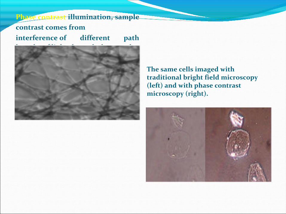
Phase contrast illumination, sample contrast comes frominterference of different path lengths of light through the sample.
The same cells imaged with traditional bright field microscopy (left) and with phase contrast microscopy (right).
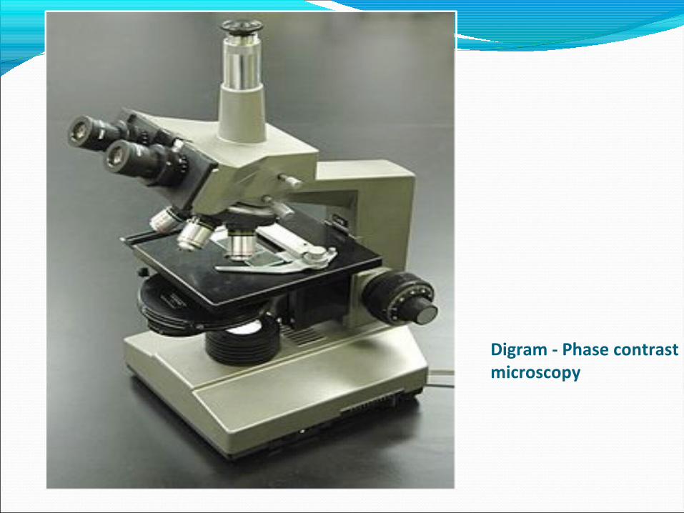
Digram - Phase contrast microscopy

Frits Zernike (1888–1966) received a Nobel prize in 1953 for his discovery of phase contrast.
MicroscopyIn positive phase contrast the object (e.g., cell component)
appears darker than the surrounding background. In negative phase contrast the object appears brighter
than the background.


Phase annulus


Zernicke realized that if he could retard the light passing through biological specimens without affecting the light passing through the surrounding medium, he could generate changes in amplitude within living cells.


How phase contrast works
A compound microscope equipped for negative phase contrast has two additional components: a “phase plate” that retards light exactly 1⁄4wavelength in a centered, ring-shaped area located at the back focal plane of the objective lens and a matching “phase annulus” in the condenser consisting of a clear ring on a black field (Figure 2-3B). The presence of the annulus and matching phase plate causes the direct (unmodified background) light to pass only through the phase ring and thus be retarded 1⁄4Ü.


The Invisible Can Be SeenThe phase contrast microscope is a vital instrument in biological and medical research. When dealing with transparent and colorless components in a cell, dyeing is an alternative but at the same time stops all processes in it. The phase contrast microscope has made it possible to study living cells, and cell division is an example of a process that has been examined in detail with it.
The phase contrast microscope is able to show components in a cell or bacteria, which would be very difficult to see in an ordinary light microscope.
Phase contrast microscopy is particularly important in biology. It reveals many cellular structures that are not visible with a simpler bright field microscope, . These structures were made visible to earlier microscopists by staining, but this required additional preparation killed the cells. The phase contrast microscope made it possible for biologists to study living cells and how they proliferate through cell division.

FLUORESCENT MICROSCOPY

A fluorescence microscope is much the same as a conventional light microscope with added features to enhance its capabilities

Basic Concepts in Fluorescence
When organic or inorganic specimens absorb and subsequently reradiate light, the process is typically a result of fluorescence or phosphorescence. Fluorescence emission is nearly simultaneous with the absorption of the excitation light as the time delay between photon absorption and emission is typically less than a microsecond. When the emission persists long after the excitation light is extinguished, the phenomenon is known as phosphorescence.
In certain classes of atoms and molecules, electrons absorb light, become energized, and then rapidly lose this energy in the form of heat and light emission. If the electron keeps its spin, the electron is said to enter a singlet state, and the kind of light that is emitted as the electron returns to ground state is called fluorescence. If the electron changes its spin when excited, it enters the triplet state, and the kind of light that is emitted as the electron returns to ground state is known as phosphorescence. Phosphorescence is much longer-lived than fluorescence. Both fluorescence and phosphorescence emissions are of particular wavelengths for specific excited electrons. Both types of emission are dependent on specific wavelengths of excitation light, and for both types of emission, the energy of excitation is greater than the energy of emission.

Fluorescence is a member of the ubiquitous luminescence family of processes in which susceptible molecules emit light from electronically excited states created by either a physical (for example, absorption of light), mechanical (friction), or chemical mechanism. Generation of luminescence through excitation of a molecule by ultraviolet or visible light photons is a phenomenon termed photoluminescence, which is formally divided into two categories, fluorescence and phosphorescence, depending upon the electronic configuration of the excited state and the emission pathway. Fluorescence is the property of some atoms and molecules to absorb light at a particular wavelength and to subsequently emit light of longer wavelength after a brief interval, termed the fluorescence lifetime. The process of phosphorescence occurs in a manner similar to fluorescence, but with a much longer excited state lifetime.


Fig. 1 Cut-away diagram of an upright microscope equipped both for transmitted light and epi-fluorescence microscopy. The vertical illuminator in the center of the diagram has the light source at one end (episcopic lamphouse) and the filter cube at the other
LIGHT SOURCES.
The most common lamps are the mercury burners, ranging in wattage from 50 to 200 W and the xenon burners ranging from 75 to 150 W. These light sources are powered by a direct current (d.c.) supply, furnishing enough start-up power to ignite the burner (by ionization of the gaseous vapor) and to keep it burning with a minimum of flicker. The power supply should have a timer to track the number of hours the burner has been in use. Arc lamps lose efficiency and are more likely to shatter, if used beyond their rated lifetime. The mercury burners do not provide even intensity across the spectrum from UV to infrared and much of the intensity of themercury burner is expended in the near UV. In recent years, there has been increasing use of lasers, particularly the argon-ion and argon–krypton-ion lasers as light sources. They have the virtues of small source size, low divergence, monochromaticity, and high mean luminance

FILTER TERMINOLOGY

Basically, there are three categories of filters: exciter filters, barrier filters, and dichromatic beam splitters (dichroic mirrors). Fluorescence filters were formerly almost exclusively made of colored glass or colored gelatin sandwiched between glass plates. Now, interference filters are used for exciter filters to pass or reject wavelengths of light with great selectivity and high transmission. Dichromatic beam splitters are specialized interference filters. Barrier filters may be either made of colored glass or interference filters


Application of flouroscence Microscopy
To utilize fluorescence, we need to label the specimen (a cell, a tissue, or a gel) with a suitable molecule (a fluorochrome) whose distribution will become evident after illumination. The fluorescence microscope is ideally suited for the detection of particular fluorochromes in cells and tissues. Early investigations showed that many specimens (minerals, crystals, resins, crude drugs, butter, chlorophyll, vitamins, inorganic compounds, etc.) fluoresce when irradiated with UV light. In the 1930s, the use of fluorochromes began in biology to stain tissue components,
bacteria, or other pathogens. Some of these stains were highly specific and they stimulated the development of the fluorescence microscope. Fluorescence microscopy has become an essential tool in biology as well as in materials science as it has attributes that are not readily available in other optical microscopy techniques.

The use of an array of fluorochromes has made it possible to identify cells and submicroscopic cellular components and entities with a high degree of specificity amid nonfluorescing material. The fluorescence microscope can reveal the presence of a single fluorescing molecule. In a sample, through the use of multiple staining, different probes can simultaneously identify several target molecules. There are specimens that autofluoresce when they are irradiated and this phenomenon is exploited in the field of botany, petrology, and in the semiconductor industry. fluorochromes (also called fluorophores), which are excited by specific wavelength irradiating light and emit light of useful intensity. Fluorochromes are stains that attach themselves to visible or subvisible structures, are often highly specific in their attachment targeting, and have significant quantum yield (the photon emission/absorption ratio). The growth in the use of fluorescent microscopes is closely linked to the development of hundreds of fluorochromes with known intensity curves of excitation and emission and well-understood biological structure
targets.

Application of fluroscence Microscope
These microscopes are often used for -
Imaging structural components of small specimens, such as cells
Conducting viability studies on cell populations (are they alive or dead?)
Imaging the genetic material within a cell (DNA and RNA)
Viewing specific cells within a larger population with techniques such as FISH

A scanning electron microscope (SEM) is a type of electron microscope that produces images of a sample by scanning it with a focused beam of electrons. The electrons interact with atoms in the sample, producing various signals that can be detected and that contain information about the sample's surface topography and composition. The most common mode of detection is by secondary electrons emitted by atoms excited by the electron beam.


Interaction with matter


Principles and capacitiesThe types of signals produced by a SEM include secondary
electrons (SE), back-scattered electrons (BSE), characteristic X-rays, light (cathodoluminescence) (CL), specimen current and transmitted electrons. Secondary electron detectors are standard equipment in all SEMs, but it is rare that a single machine would have detectors for all possible signals. The signals result from interactions of the electron beam with atoms at or near the surface of the sample. In the most common or standard detection mode, secondary electron imaging or SEI, the SEM can produce very high-resolution images of a sample surface, revealing details less than 1 nm in size. Due to the very narrow electron beam, SEM micrographs have a large depth of field yielding a characteristic three-dimensional

appearance useful for understanding the surface structure of a sample. This is exemplified by the micrograph of pollen shown above. Back-scattered electrons (BSE) are beam electrons that are reflected from the sample by elastic scattering. BSE
are often used in analytical SEM along with the spectra made from the characteristic X-rays, because the intensity of the BSE signal is strongly related to the atomic number (Z) of the specimen. BSE images can provide information about the distribution of different elements in the sample. For the same reason, BSE imaging can image colloidal gold immuno-labels of 5 or 10 nm diameter, which would otherwise be difficult or impossible to detect in secondary electron images in biological specimens. Characteristic X-rays are emitted when the electron beam removes an inner shell electron from the sample, causing a higher-energy electron to fill the shell and release energy. These characteristic X-rays are used to identify the composition and measure the abundance of elements in the sample.

Functional Principle


Biological samplesFor SEM, a specimen is normally required to be completely dry, since the
specimen chamber is at high vacuum. Hard, dry materials such as wood, bone, feathers, dried insects, or shells can be examined with little further treatment, but living cells and tissues and whole, soft-bodied organisms usually require chemical fixation to preserve
and stabilize their structure. Fixation is usually performed by incubation in a solution of a buffered chemical fixative, such as glutaraldehyde, sometimes in combination with formaldehyde and other fixativesa and optionally followed by postfixation with osmium tetroxide.The fixed tissue is then dehydrated. Because airdrying causes collapse and shrinkage, this is commonly achieved by replacement of water in the cells with organic
.
solvents such as ethanol or acetone, and replacement of these solvents in turn with a transitional fluid such as liquid carbon dioxide by critical point drying. The carbon dioxide is finally removed while in a supercritical state, so that no gas-liquid interface is present within the sample during drying. The dry specimen is usually mounted on a
specimen stub using an adhesive such as epoxy resin or electrically conductive double-sided adhesive tape, and sputter-coated with gold or gold/palladium alloy before examination in the microscope

Scanning process and image formation
In a typical SEM, an electron beam is thermionically emitted from an electron gun fitted with a tungsten filament cathode. Tungsten is normally used in thermionic electron guns because it has the highest melting point and lowest vapour pressure of all metals, thereby allowing it to be heated for electron emission, and because of its low cost.
The electron beam, which typically has an energy ranging from 0.2
keV to 40 keV, is focused by one or two condenser lenses to a spot about 0.4 nm to 5 nm in diameter. The beam passes through pairs of scanning coils or pairs of deflector plates in the electron column, typically in the final lens, which deflect the beam in the x and y axes so that it scans in a raster fashion over a rectangular area of the sample surface.


SEMs may have condenser and objective lenses, but their function is to focus the beam to a spot, and not to image the specimen.

Detection of secondary electronsThe most common imaging mode collects low-energy (<50 eV) secondary
electrons that are ejected from the k-shell of the specimen atoms by inelastic scattering interactions with beam electrons. Due to their low energy, these electrons originate within a few nanometers from the sample surface. The electrons are detected by an Everhart- Thornley detector
Detection of backscattered electronsBSE detectors are usually either of scintillator or of semiconductor types.X-ray microanalysisX-rays, which are produced by the interaction of electrons with the sample,
may also be detected in an SEM equipped for energy-dispersive X-ray spectroscopy or wavelength dispersive X-ray spectroscopy


Resolution Factors affecting the resolution are: i) The diameter of the electron beam ii) Scattering within the specimen iii) The signal-to-noise ratio iv) External disturbances due to 1. Electric of magnetic fields2. Mechanical vibrations

ADVANTAGESHigh resolution and magnification3-D Topographical imagingCompatible with PC technologies and softwaresFast AnalysingStore data in digital formEasier sample preparation techniquesDISADVANTAGESCan not analys fluid or gas compoundsExpensive InstrumentationWasting time on sample preparationConstant voltage during analysing

RESULTSEM uses electrons instead of light to form an image.
developed new areas of study & still helping.popular among researchers due to their wide range of applications
CONCLUSIONSEM;provides detailed surface data of solid samplesinforms external morphology, chemical composition, crystalline structure
SAMPLE;must be prepared before placed

Transmission Electron Microscope

Transmission electron microscopy (TEM) is a microscopy technique in which a beam of electrons is transmitted through an ultra-thin specimen, interacting with the specimen as it passes through. An image is formed from the interaction of the electrons transmitted through the specimen; the image is magnified and focused onto an imaging device,
such as a fluorescent screen, on a layer of photographic film, or to be detected by a sensor such as a CCD camera.


Working PrincipleTEM works like a slide projector. A projector shines a beam of light which
transmits through the slide. The patterns painted on the slide only allow certain parts of the
light beam to pass through. Thus the transmitted beam replicates the patterns on the slide,
forming an enlarged image of the slide when falling on the screen. TEMs work the same way
except that they shine a beam of electrons (like the light in a slide projector) through the specimen (like the slide). However, in TEM, the transmission of electron beam is highly dependent on the properties of material being examined. Such properties include density, composition, etc. For example, porous material will allow more electrons to pass through while dense material will allow less. As a result, a specimen with a non-uniform density can be examined by this technique. Whatever part is transmitted is projected onto a phosphor screen for the user to see.

ELECTRON SOURCE (GUN):-


The first and basic part of the transmission electron microscope is the source of electrons. It is usually a V-shaped filament made of LaB6 or W (tungsten) that is wreathed with Wehnelt electrode (Wehnelt Cap). Due to negative potential of the electrode, the electrons are emitted from a small area of the filament (point source). A point source is important because it emits monochromatic electrons (with similar energy). In this, a positive electrical potential is applied to the anode, and the filament (cathode) is heated until a stream of electrons is produced. The electrons are accelerated by the positive potential down the column, and because of the negative
potential of cap, all electrons are repelled toward the optic axis. A collection of electrons occurs in the space between the Filament tip and Cap , which is called a space charge. Those electrons at the bottom of the space charge (nearest to the anode) can exit the gun area through the small (<1 mm) hole in the Wehnelt Cap and then move down the column to be later used in imaging.

2) CONDENSER LENS:- The stream of the electron from the electron gun is then focussed to a small, thin,
coherent beam by the use of condenser lenses. The first lens determines the “spot size”; the general size range of the final spot that strikes the sample. The second lens actually changes the size of the spot on the sample.
3) CONDENSER APERTURE:- A condenser aperture is a thin disk or strip of metal with a small circular through-
hole. It is used to restrict the electron beams and filter out unwanted scattered electrons before image formation.
4) SAMPLE: - The beam from the condenser aperture strikes the sample and the electron-sample
interaction takes place in three different ways. One is unscattered electrons (transmitted beam), elastically scattered electrons (diffracted beam) and inelastically scattered electrons.

5) OBJECTIVE LENS: - The main function of the objective lens is to focuses the transmitted electron from the sample
into an image. 6) OBJECTIVE APERTURE:- Objective aperture enhances the contrast by blocking out high-angle diffracted electrons. 7) SELECTED APERTURE:- It enables the user to examine the periodic diffraction of electron by ordered arrangements of atoms in the sample. 8) PROJECTOR LENS:- The projector lens are used to expand the beam onto the phosphor screen. 9) SCREEN:- Imaging systems in a TEM consists of a phosphor screen, which may be made of fine (10-100 micro meter) particulate zinc sulphide, for direct observation by the operator. 10) IMAGE PATTERN:- The image strikes the phosphor screen and light is generated, allowing the users to see the
image. The darker areas of the image represent those areas of the sample that fewer electrons are transmitted. The lighter areas of the image represent those areas of the sample that more electrons were transmitted.

Sample Preparation Sample preparation is important for electron microscopy. There are three main steps for sample
preparation: Processing, embedding and polymerization. Processing This includes: fixation, rinsing, post fixation, dehydration and infiltration. Fixation It stabilizes the cell structure. There is minimum alteration to cell morphology and volume.
Glutaraldehyde is often used as the fixative in TEM. As a result of glutaraldehyde fixation the protein molecules
are covalently cross linked to their neighbors. 2) Rinsing The samples should be washed with a buffer to maintain the pH. For this purpose, sodium
cacodylate buffer is often used which has an effective buffering range of 5.1-7.4. The sodium cacodylate buffer thus prevents excess acidity which may result from tissue fixation during microscopy.

3) Post fixation A secondary fixation with osmium tetroxide (OsO4), which is to increase the
stability and contrast of fine structure. OsO4 binds phospholipid head regions, which creating contrast with the neighbouring protoplasm (cytoplasm). OsO4 helps in the stabilization of many proteins by transforming them into gels without destroying the structural features. Tissue proteins, which are stabilized by OsO4 and does not coagulated by alcohols during dehydration
4) Dehydration The water content in the tissue sample should be replaced with an organic solvent
since the epoxy resin used in infiltration and embedding step are not miscible with water.
5) Infiltration Epoxy resin is used to infiltrate the cells. It penetrates the cells and fills the space to
give hard plastic material which will tolerate the pressure of cutting. 6) Embedding: After processing the next step is embedding. This is done using flat molds.
7) Polymerization Next is polymerization step in which the resin is allowed to set overnight at
a temperature of 60 degree in an oven.. 8) SectioningThe specimen must be cut into very thin sections for electron microscopy so
that the electrons are semitransparent to electrons. These sections are cut on an ultramicrotome which is a device with a glass or
diamond knife. For best resolution the sections must be 30 to 60 nm. The resin block can be made ready for the sectioning by trimming it at the tip with a razor blade or black trimmer so that the smallest cutting face is available. Fix the block to a microtome and cut the sections. Sections float onto a surface of liquid held in trough and remain together in a form of ribbon. Freshly distilled water is generally used to fill the trough. These sections are then collected onto a copper grid and viewed under the microscope.

Advantages TEMs find application in cancer research, virology, materials science as well
as pollution, nanotechnology, and semiconductor research. TEM is however a significant achievement of quantum mechanical
understanding of electron. It was a major step in magnification studies and obtaining better resolution than optical microscopes and hence is a very important building block in study of application of quantum mechanics. Moreover it is very commonly used in studies of material structures and properties and for other experimental purposes.

Limitations There are a number of drawbacks to the TEM technique. Many materials require
extensive sample preparation to produce a sample thin enough to be electron transparent, which makes TEM analysis a relatively time consuming process with a low throughput of samples. The structure of the sample may also be changed during the preparation process. Also the field of
view is relatively small, raising the possibility that the region analysed may not be characteristic of the whole sample. There is potential that the sample may be damaged by the electron beam, particularly in the case of biological materials.
Related Documents


