37 STUDY OF MECHANICAL BEHAVIOR IN AUSTENITIC STAINLESS STEEL 316 LN WELDED JOINTS D Harish Kumar 1 * and A Somi Reddy 1 *Corresponding Author: D Harish Kumar, [email protected] Low carbon grade type 316 austenitic stainless steel, alloyed with nitrogen designated as 316 LN SS exhibit superior strength at ambient and high temperatures, excellent corrosion resistance to replace other expensive materials. Austenitic stainless steel get sensitized during welding. The problem of sensitization can be over come by decreasing the carbon content. Reducing the carbon content would cause drastic reduction in mechanical properties. Replacing much of the carbon with nitrogen can offset this deterioration in mechanical properties. Nitrogen in solid solution is the most beneficial alloying element in promoting high strength in austenitic SS without sacrificing their good ductility and toughness. The upper limit of nitrogen is set on considerations of minimizing scatter in mechanical properties and improving weldability. Phosphorous, sulphur and silicon are treated as impurities having adverse effects on weldability. The selection of the material is based on its good combination of tensile, creep strength, ductility and its high resistance to stress corrosion cracking and sensitization. Nickel content has been known as an element that stabilizes austenite and increases toughness. Nitrogen has diverse effects on the microstructure and solidification cracking behavior of type 316 stainless steel. In the present paper an attempt has been made to present the influencing factors on the weldability of 316 LN SS. The welding processes such as single pass activated TIG (A-TIG), multi-pass activated TIG (MP-TIG) welding and Laser welding were discussed in relation to the 316 LN austenitic stainless steel. Residual stresses are a system of self-equilibrating stresses, which may exist when it is free from external loads or forces. The existence of such stresses have been analyzed and compared. Non-destructive techniques have been used for measuring residual stresses and defects in welding. The purpose of this review is to investigate weldability of 316 LN SS, study the beneficial effect on fully austenitic steels with particular emphasis on nitrogen-alloyed and stabilized stainless steels. Keywords: Austenitic stainless steel, Sensitization, Weldability, Residual stresses, Hot cracking and nitrogen ISSN 2278 – 0149 www.ijmerr.com Vol. 2, No. 1, January 2013 © 2013 IJMERR. All Rights Reserved Int. J. Mech. Eng. & Rob. Res. 2013 1 KITS, Warangal 506371, Andhra Pradesh, India. 2 Vivekananda Institute of Technology & Science, Karimnagar 505001, Andhra Pradesh, India. Research Paper

Welcome message from author
This document is posted to help you gain knowledge. Please leave a comment to let me know what you think about it! Share it to your friends and learn new things together.
Transcript

37
Int. J. Mech. Eng. & Rob. Res. 2013 D Harish Kumar and A Somi Reddy, 2013
STUDY OF MECHANICAL BEHAVIORIN AUSTENITIC STAINLESS STEEL 316 LN
WELDED JOINTSD Harish Kumar1* and A Somi Reddy1
*Corresponding Author: D Harish Kumar,[email protected]
Low carbon grade type 316 austenitic stainless steel, alloyed with nitrogen designated as 316LN SS exhibit superior strength at ambient and high temperatures, excellent corrosion resistanceto replace other expensive materials. Austenitic stainless steel get sensitized during welding.The problem of sensitization can be over come by decreasing the carbon content. Reducing thecarbon content would cause drastic reduction in mechanical properties. Replacing much of thecarbon with nitrogen can offset this deterioration in mechanical properties. Nitrogen in solidsolution is the most beneficial alloying element in promoting high strength in austenitic SS withoutsacrificing their good ductility and toughness. The upper limit of nitrogen is set on considerationsof minimizing scatter in mechanical properties and improving weldability. Phosphorous, sulphurand silicon are treated as impurities having adverse effects on weldability. The selection of thematerial is based on its good combination of tensile, creep strength, ductility and its high resistanceto stress corrosion cracking and sensitization. Nickel content has been known as an elementthat stabilizes austenite and increases toughness. Nitrogen has diverse effects on themicrostructure and solidification cracking behavior of type 316 stainless steel. In the presentpaper an attempt has been made to present the influencing factors on the weldability of 316 LNSS. The welding processes such as single pass activated TIG (A-TIG), multi-pass activatedTIG (MP-TIG) welding and Laser welding were discussed in relation to the 316 LN austeniticstainless steel. Residual stresses are a system of self-equilibrating stresses, which may existwhen it is free from external loads or forces. The existence of such stresses have been analyzedand compared. Non-destructive techniques have been used for measuring residual stressesand defects in welding. The purpose of this review is to investigate weldability of 316 LN SS,study the beneficial effect on fully austenitic steels with particular emphasis on nitrogen-alloyedand stabilized stainless steels.
Keywords: Austenitic stainless steel, Sensitization, Weldability, Residual stresses, Hot crackingand nitrogen
ISSN 2278 – 0149 www.ijmerr.comVol. 2, No. 1, January 2013
© 2013 IJMERR. All Rights Reserved
Int. J. Mech. Eng. & Rob. Res. 2013
1 KITS, Warangal 506371, Andhra Pradesh, India.2 Vivekananda Institute of Technology & Science, Karimnagar 505001, Andhra Pradesh, India.
Research Paper
38
Int. J. Mech. Eng. & Rob. Res. 2013 D Harish Kumar and A Somi Reddy, 2013
INTRODUCTIONNitrogen added stainless steels exhibit severalunique characteristics such as superiorstrength at ambient as well as hightemperatures, excellent corrosion resistancein various media and are candidate materialsto replace more expensive materials. In 316LN SS for nuclear service, carbon has beenreduced to decrease the propensity for intergranular corrosion. Nitrogen is added mainlyto recover the high strength and elevatedtemperature properties associated with theloss of carbon in comparison with conventional316 (Bandy and Van, 1985). Nitrogen isexpected to have strong influence on the hotcracking behavior (Bhanu et al., 1993).Nitrogen in weld metal arises from varioussources such as prior content in the basemetal, intentional addition through the shieldinggas or as inadvertent pick up due toinadequate shielding during welding. Nitrogenresides in weld metal in the following forms(Bhanu et al., 1994): (1) interstitial nitrogendissolved in the lattice structure-may collectaround lattice defects, (2) combined nitrogenpresent as nitrides, and (3) occlude nitrogenin pores. It is the first two forms of nitrogen thataffect the metallurgical behavior of the weldmetal. Nitrogen has strong stabilizing effect onaustenite when present in iron Fe-N austeniteis isomorphos with Fe-C austenite in the Fe-C-N system. The solubility of nitrogen inaustenite is enhanced by several solutes sucha Cr,Mn and to great extent by V and Nb.TheMo increases solubility slightly while C, Si andNi tend to decrease it (Borland, 1960). Thenitrogen activity in steel decreases whenelements with N-affinity such as Al, Cr, or Nbare added, while it increases with additions of
C, Ni, P, S or Si (Bhanu, 1994). Nitrogen insolid solution is the most beneficial alloyingelement in promoting high strength inaustenitic SS without sacrificing their goodductility and toughness as long as the solubilitylimit of nitrogen in austenite is not exceeded(Brooks, 1974). Together with chromium andmolybdenum, nitrogen additions to austeniticSS also improve resistance to pitting andcrevice corrosion (Borland and Younger, 1960;and Briant et al., 1982) sensitization (Dundasand Bond, 1975; Eckenrod and Kovach, 1979;and Dutta et al., 1993), and Stress CorrosionCracking (SCC) (Eckenrod and Kovach, 1979;and Folkhard, 1988). Due to the abovereasons, nitrogen-added austenitic SS arefinding increasing applications in criticalindustries. During welding of austenitic SS,besides sensitization, the most commonlyencountered problem is that of hot cracking ofthe weld metal. The most common methodadopted is by intentionally rendering theaustenitic SS weld deposit inhomogeneous byretaining some amount of high temperatured-ferrite to room temperature (Garner, 1977).Gill et al. (1987) reported that it was difficult toseparate the beneficial effect of nitrogen onpitting corrosion resistance from its tendencyto stabilize austenite and thereby preventformation of d-ferrite. There is a generalconsensus in literature that nitrogen additionsimprove pitting and crevice corrosionresistance of austenitic SS and theirweldments, provided the solubility limit ofnitrogen is not exceeded (Hull, 1967a and1967b; Jargelius and Vallin, 1986; Goodwin,1988; Kamachi et al., 1996; and Kwok et al.,2006). The beneficial effect of nitrogen onpitting corrosion resistance of SS is attributedto improved passivity.

39
Int. J. Mech. Eng. & Rob. Res. 2013 D Harish Kumar and A Somi Reddy, 2013
Chemical composition, mechanicalproperties of 316 LN SS were given in Tables1 and 2.
metals. Contamination of the weld region withcopper or zinc should be avoided, since theseelements can form low melting pointcompounds, which in turn can create weldcracking. Fusion welding is widely used tofabricate the reactor vessel and piping due toits complexity and size involved. Serviceexperience has shown that the cracking in weldjoints is the life limiting factor (Manning et al.,1980; and Laha et al., 2007). Major weldedcomponent often have to be taken out ofservice at a point in time where, little damagewould have occurred in the parent material. Ingeneral, Tungsten Inert Gas welding (TIG)process with and without filler metal are usedto join this class of materials. However, themost constraints of TIG welding of stainlesssteel lie in the limited thickness of the materialwhich can be welded in a single pass, poortolerance to chemical composition of thedeposited weld metal leading to the formationof undesirable phases and the low productivityof joining. In this process, weld penetrationachievable in single pass welding of StainlessSteel (SS) is limited to 3 mm when using argonas shielding gas. The penetration capabilityof the arc in TIG welding can be significantlyincreased by application of a flux coatingcontaining certain inorganic compounds on thejoint surface prior to welding (Matsuda et al.,1982; and Mathew et al., 2007). A-TIG weldingis nothing but an activated TIG process usingmulti-component flux. The flux in the form ofpaste is generally applied on the surfaces ofthe joint before welding. Using A-TIG welding,penetration upto 300% has been achieved inaustenitic stainless steel. Use of activatedfluxes during TIG welding has been found toreduce the magnitude of tensile residualstresses and distortion in welds. Multi-pass
Table 1: Chemical Composition (Wt%)
Element Minimum Maximum
Chromium 16.0 18.0
Molybdenum 2.00 3.00
Nickel 10.0 14.0
Manganese 2.0
Phosphorus 0.045
Sulfur 0.030
Silicon 0.75
Carbon 0.030
Nitrogen 0.10 0.16
Iron Balance
Property ASTM A 240
Yield Strength, 0.2% offset 30 ksi 205 MPa
Ultimate Tensile 75 ksi
Strength 515 MPa
Elongation in 2" (51 mm) 40%
Hardness 217 Brinell 95 HRB
Table 2: Room Temperature Properties
WELDABILITY OF 316 LN SSThe austenitic stainless steels are consideredthe most weldable of the stainless steels. Theyare routinely joined by all fusion and resistancewelding processes. Two importantconsiderations for weld joints in these alloysare: (1) avoidance of solidification cracking,and (2) preservation of corrosion resistanceof the weld and heat-affected zones. Type 316LN stainless steel often is weldedautogenously. If filler metal must be used forwelding Type 316 LN, it is advisable to utilizethe low carbon Types 316 L or E318 filler
40
Int. J. Mech. Eng. & Rob. Res. 2013 D Harish Kumar and A Somi Reddy, 2013
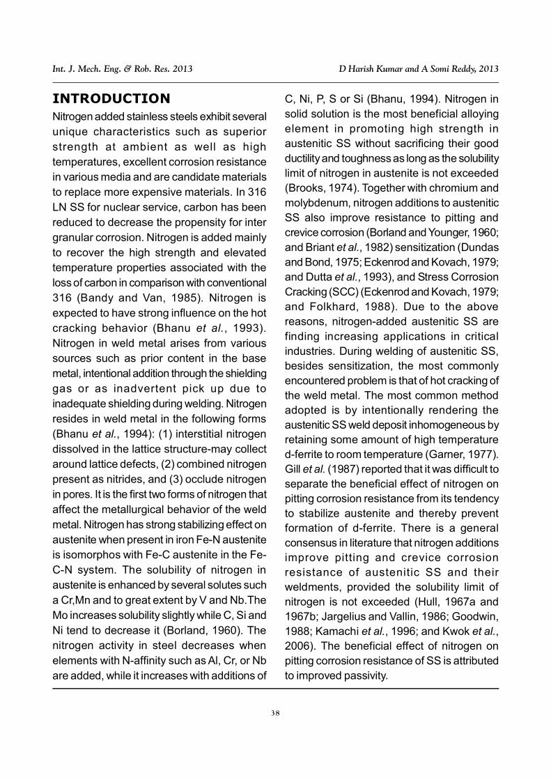
(TIG) welding process generally uses aV-groove for plates of 6mm thickness and afiller wire of 316 L SS of 1.6mm diameter. Toreveal the ä-ferrite in the weld metal immersionetching in boiling murakkami etchant isgenerally used. This etchant consists of (10gm potassium ferric cyanide, 10 gmpotassium hydroxide and 100 ml water). Thepresence of -phase can be detected byetching with modified murakkami etchant (30gm potassium ferric cyanide, 30 gmpotassium hydroxide and 150 ml water).Wealth of information exist in the literature onthe welding process effects of 316 LN material
on the low temperature and high temperaturemechanical properties. A-TIG and multipassTIG welding processes have been used to join316 LN material and evaluated and comparedthe mechanical properties, microstructures ofthese weldments.
The chemical compositions 316 L(N) SS,316 L(N) weld metal of MP (TIG), and 316L(N) weld metal of (A-TIG) have been givenin Table 3.
The welding parameters of A-TIG and multi-pass TIG welding of 316 LN have been givenin Table 4.
Material C Cr Ni Mo Mn Si S P N
316 L(N) SS Base Metal 0.028 17.5 12.2 2.3 1.65 0.44 0.01 0.024 0.085
316 L(N) Weld Metal (MPTIG) 0.026 19 11 2.3 1.5 0.53 0.01 0.025 0.087
316 L(N) Weld Metal (ATIG) 0.030 17.5 12.0 204 1.45 0.5 0.005 0.021 0.09
Table 3: The Chemical Compositions 316 L(N)SS, 316 L(N) Weld Metal of MP (TIG),and 316 L(N) Weld Metal of (A-TIG)
Welding Parameters A-TIG Multi-Pass TIG
Current (A) 200 110
Voltage (V) 12.5 12
Travel Speed (mm/min) 120 80
Number of Layers Single Pass 7 Passes
Heat Input (KJ/mm) 1250 J/mm 990 J/mm
Plate Thickness 6 mm 6 mm
Table 4: The Welding Parameters of A-TIG and Multi-Pass TIG Welding of 316 LN
HYBRID WELDINGIn hybrid tests, torch of GMAW (gas metal arcwelding) was placed next to the laser weldinghead with a handling system allowingmovements necessary for changing interactionparameters. The GMAW machine had amodified contact nozzle. The shielding gas wasguided to the melt via an extra nozzle. Theparameters of GMAW were kept in a moderate
level, i.e., the arc current and the voltage wereselected in order to stay in a so-called “cold-arc” field. The angle of the torch and theimpingement point of filler wire were varied.The material in hybrid experiments was anaustenitic stainless steel AISI 316 LN. Testpieces were as in filler wire experiments, butone or two root welds were made using onlywith filler wire and laser beam.

41
Int. J. Mech. Eng. & Rob. Res. 2013 D Harish Kumar and A Somi Reddy, 2013
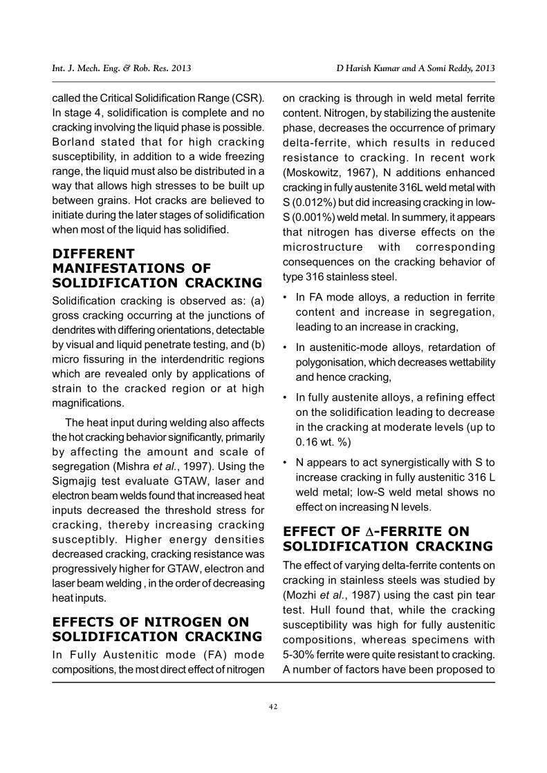
The main interest in welding by a hybridprocess for the narrow gap configuration was
any cracks formed. In stage 3, the solid crystalsare in an advanced stage of development andthe free passage of liquid is prevented. Theliquid is present in very small quantity. At thisstage, If stress is applied which cannot be filledby the remaining liquid phase. This stage,during which much of the cracking occurs, is
to ascertain if it is possible to have the arcinside the groove (Figure 1).
Figure 1: Cross-Section of the Hybrid Weld, Thickness of 20 mm, Power 3 kW; WeldingSpeed, 0.5-0.7 m/min
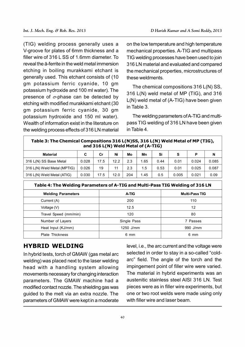
SOLIDIFICATION CRACKINGSolidification cracking occurs predominantlyby the solutes to form low-melting phases,which under the action of shrinkage stressesaccompanying solidification cause cracking.The initial theories (Medovar, 1954) took intoaccount the fact cracking is associated withsegregation; the wider the liquid-solid rangeof the alloy, the grater the susceptibility. The‘Generalized Theory’ of cracking wasproposed by Menon and Kotecki (1989).According to Borland, solidification involvesfour stages that are classified according to thedistribution of the liquid and solid phases, asshown in Figure 2 for a binary alloy. In stage 1,the solid phase is dispersed, the liquid phaseis continuous and both the phases canaccommodate relative movement. In stage 2,both the liquid and solid phases arecontinuous, but the solid dendrites areinterlocked and only the liquid is capable ofmovement. At this stage, the liquid can heal
Figure 2: Effect of ConstitutionalFeatures on Cracking Susceptibilityin Binary Systems According to the
Generalized Theory of Borland (1960)
42
Int. J. Mech. Eng. & Rob. Res. 2013 D Harish Kumar and A Somi Reddy, 2013
called the Critical Solidification Range (CSR).In stage 4, solidification is complete and nocracking involving the liquid phase is possible.Borland stated that for high crackingsusceptibility, in addition to a wide freezingrange, the liquid must also be distributed in away that allows high stresses to be built upbetween grains. Hot cracks are believed toinitiate during the later stages of solidificationwhen most of the liquid has solidified.
DIFFERENTMANIFESTATIONS OFSOLIDIFICATION CRACKINGSolidification cracking is observed as: (a)gross cracking occurring at the junctions ofdendrites with differing orientations, detectableby visual and liquid penetrate testing, and (b)micro fissuring in the interdendritic regionswhich are revealed only by applications ofstrain to the cracked region or at highmagnifications.
The heat input during welding also affectsthe hot cracking behavior significantly, primarilyby affecting the amount and scale ofsegregation (Mishra et al., 1997). Using theSigmajig test evaluate GTAW, laser andelectron beam welds found that increased heatinputs decreased the threshold stress forcracking, thereby increasing crackingsusceptibly. Higher energy densitiesdecreased cracking, cracking resistance wasprogressively higher for GTAW, electron andlaser beam welding , in the order of decreasingheat inputs.
EFFECTS OF NITROGEN ONSOLIDIFICATION CRACKINGIn Fully Austenitic mode (FA) modecompositions, the most direct effect of nitrogen
on cracking is through in weld metal ferritecontent. Nitrogen, by stabilizing the austenitephase, decreases the occurrence of primarydelta-ferrite, which results in reducedresistance to cracking. In recent work(Moskowitz, 1967), N additions enhancedcracking in fully austenite 316L weld metal withS (0.012%) but did increasing cracking in low-S (0.001%) weld metal. In summery, it appearsthat nitrogen has diverse effects on themicrostructure with correspondingconsequences on the cracking behavior oftype 316 stainless steel.
• In FA mode alloys, a reduction in ferritecontent and increase in segregation,leading to an increase in cracking,
• In austenitic-mode alloys, retardation ofpolygonisation, which decreases wettabilityand hence cracking,
• In fully austenite alloys, a refining effecton the solidification leading to decreasein the cracking at moderate levels (up to0.16 wt. %)
• N appears to act synergistically with S toincrease cracking in fully austenitic 316 Lweld metal; low-S weld metal shows noeffect on increasing N levels.
EFFECT OF -FERRITE ONSOLIDIFICATION CRACKINGThe effect of varying delta-ferrite contents oncracking in stainless steels was studied by(Mozhi et al., 1987) using the cast pin teartest. Hull found that, while the crackingsusceptibility was high for fully austeniticcompositions, whereas specimens with5-30% ferrite were quite resistant to cracking.A number of factors have been proposed to
43
Int. J. Mech. Eng. & Rob. Res. 2013 D Harish Kumar and A Somi Reddy, 2013
explain the beneficial effects of delta-ferriteon cracking behaviour:
• The higher solubility for impurity elementsin delta-ferrite leads to less interdendriticsegregation and reduces crackingtendency (Mozhi et al., 1985).
• The presence of ferrite results in a largerinterface area due to the solid statetransformation to austenite that beginssoon after solidification. The increased areadisperses the concentration of impurityelements at the grain boundaries.
• The presence of ferrite refines the grain sizeof the solidified metal, which results in bettermechanical and cracking resistance.
• The ductility of ferrite at high temperaturesis greater than that of austenite, allowingrelaxation of thermal stresses.
• The lower thermal expansion coefficient offerrite as compared to austenite results inless contraction stresses and fissuringtendency.
EFFECTS OF IMPURITY ANDALLOYING ELEMENTS ONCRACKINGThe elements such as, sulphur, phosphorous,boron, niobium, titanium, and silicon wereidentified as most harmful. Among theelements whose effects on cracking wereinvestigated, Hull found molybdenum,manganese and nitrogen beneficial. Sulphuris known to be an undesirable impurity inwelding of stainless steels due to the formationof low-melting sulphide films along theinterdendritic and grain-boundary regions.Sulphur is almost insoluble in all three majorconstituents of stainless steel, viz., iron,
chromium and nickel. Sulphur is stronglyrejected at the liquid during solidification ofaustenite, rapidly lowering the melting pointinterdendritic liquid. On the other hand, delta-ferrite shows higher solubility for elements likeS, P, Si and Nb. Phosphorous ranks next tosulphur in the list of elements detrimental togood weldablity in stainless steels. Like,sulphur, P forms low-melting eutectics with iron,chromium and nickel (Ogawa et al., 1982)identifies phosphorous as particularly harmfulin fully austenitic stainless steels since it has astrong tendency to spread as liquid films.Further, it has been stated that the lowdiffusivity of P in both austenitic and ferriticphases even at high temperatures virtuallyprecludes homogenization (Osozawa andOkada, 1976). Further, the addition oflanthanum and other rare-earths has beenfound highly effective in binding the P and Sas stable compounds (Parvathavarthini et al.,1994). Ti and Nb increase cracking by formingvarious eutectics in conjunction with S, N andC. The most deleterious phases in such steelsare probably the carbosulphides such astitanium, followed by the carbonitrides and thecarbides. In Ti-bearing stainless steels, theamount of these phases increases withincreasing stabilization ratio, i.e. (Ti, Nb)/(C, N). A lower ratio is desirable for minimizingthe cracking propensity. The Ti-bearing fullyaustenitic stainless steel Ti/(C + N) between 2and 3 was found optimal.
SENSITIZATIONMaterial degradation of stainless steels beginswhenever they experience temperature in therange 450-800 °C. After sufficient time attemperature, intermetallic compounds(principally Cr carbides) precipitate in grain

44
Int. J. Mech. Eng. & Rob. Res. 2013 D Harish Kumar and A Somi Reddy, 2013
boundaries and (later) inside the grains aswell. This precipitation creates a conditionknown as sensitization that ruins corrosionresistance while reducing cryogenic ductilityand toughness. With continued aging, propertydegradation at 4 K is progressive. Thetoughness at 4 K declines gradually at first andfalls more abruptly as intergranual fracturebegins to dominate. Service embrittlementresults if the precipitates become extensiveenough to establish a continuous, low-energypath for cracks. A transgranular-to-inter-granular fracture transition then occurs,constituting unacceptable embrittlement.Sensitization effects are determined by thediffusion rates of the relevant atomic speciesin particular steels. The primary cause ofsensitization in stainless steel is C coming outof solution and forming the intermetalliccompound, M
23C
6. Nitrogen comes out of
solution at a slower rate, so that in micro alloyed316 LN steels (described below) the formationof nitrides such as Cr
2N becomes an important
secondary factor. The aging time required tosensitize a steel is fixed by the details of alloycomposition, condition, and temperature.Time-temperature-sensitization curves wereconstructed recently to predict the aging timefor some 316 LN-type steels. The curvespurport to illustrate basic compositional effectsand provide guidance to avoid sensitization.Because of uncertainties, published data forindividual alloys must be verified before anyapplication is made.
GENERAL CORROSIONPROPERTIES OF 316 LN
Pitting Corrosion
Austenitic SS are susceptible to a number ofmanifestations of localised corrosion attacks,
of which the major problem is caused bysensitization which can cause failure of weldedcomponents by Intergranular Stress CorrosionCracking (IGSCC) in the presence of residualstresses. Sensitization occurs due to Cr
23C
6
precipitation, when the austenitic SS is heatedin the temperature range of 723 to 1123 K,which causes depletion of Cr from regionsadjacent to the grain boundary to a level thusmaking the steel susceptible to IntergranularCorrosion (IGC) and IGSCC attacks.Austenitic SS get sensitized during service inthe above temperature range or duringwelding. High heat input during weldingincreases the risk of sensitization because theslow cooling rates lead to longer residencetime in the sensitization temperature range.The problem of sensitization can be overcomeby decreasing the carbon content. However,reducing the carbon content would causedrastic reduction in mechanical properties.Replacing much of the carbon with nitrogencan offset this deterioration in mechanicalproperties.The presence of -ferrite in the weldmetal causes partitioning of alloying elements,and extensive segregation of sulphur andphosphorous at the -ferrite/austeniteinterfaces. These micro-chemicalheterogeneities in the weld metal result inpreferential corrosion attacks. Presence of-ferrite reduces the critical pitting potential ofthe austenitic SS by providing susceptiblepitting sites (Pehlke and Elliott, 1960; andPickering, 1988). In the case of type 304 SSweld metal, the most susceptible sites forpitting corrosion were the / interfaces,where extensive segregation of S and Pcaused difficulty in passivation (Stevens,1989). In type 316 SS weld metal, thepreferential sites for pit initiation were found

45
Int. J. Mech. Eng. & Rob. Res. 2013 D Harish Kumar and A Somi Reddy, 2013
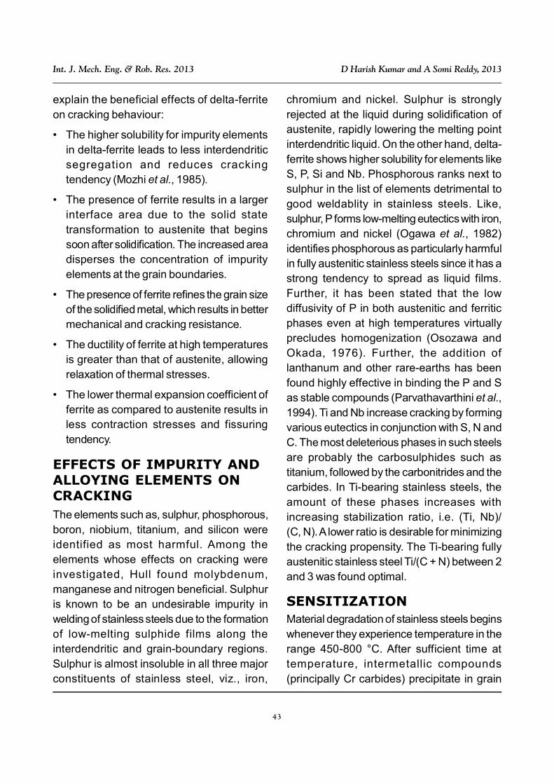
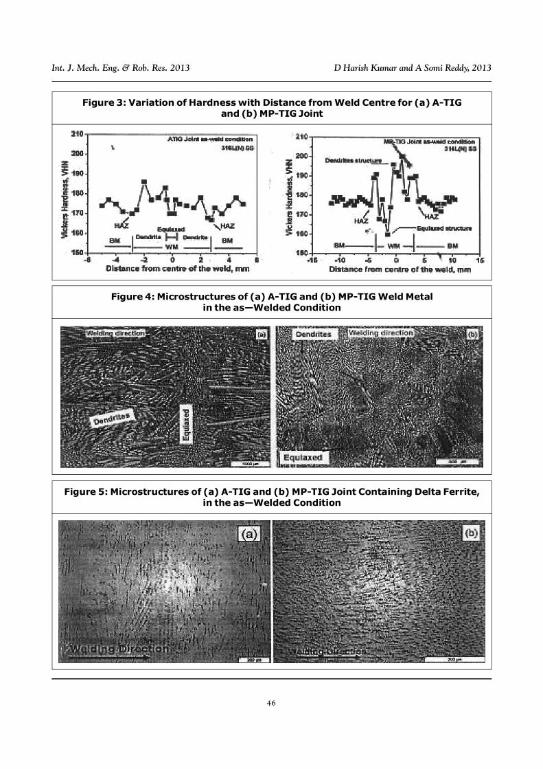
equiaxed zone in weld metal was found to growcontinuously along the joints, whereas it isdiscontinuous in the MP-TIG joint (Figure 4).The mechanisms and conditions for theformation of dendritic and equiaxed grains inweld metal have been discussed by Shaikhet al. (2000). The epitaxial and competitivegrowth of solidified weld metal from the basemetal leads to the formation of dendriticstructure in weld metal when heat input isrelative low and cooling rate is relatively high.The formation of equiaxed grain in weld poolwill be favored under the condition of high heatinput and low cooling rate leading to thedendrite fragmentation, grain detachment andheterogeneous nucleation. In both the joints,delta-ferrite of vermicular morphology wasobserved in between the dendrites andequiaxed grains. Orientation of the ä-ferrite ofvermicular morphology was observed inbetween the dendrites and equiaxed grains.Orientation of the -ferrite was nearlyperpendicular to the welding direction in theA-TIG joints, whereas it was parallel to thewelding direction in the MP-TIG joint (Figure5). More amount of -ferrite was observed inthe MP-TIG joint (9 FN) than in the A-TIG joint(1.3 FN). The variations of hardness acrossthe joints are shown in Figure 3. Hardnessvariation across the joints is reflected in themicrostructural variations. Coarse grain HAZin the A-TIG joint displayed lower hardness thanthat in the MP-TIG joint. Hardness variationacross the weld metal was found to dependon microstructure. The equiaxed weldpossessed lower hardness than the dendriticweld metal. Relatively more uniform hardnessvariation was observed in the A-TIG joint thanin the MP-TIG joint.
to be the core of the austenite cells wheredepletion of Mo occurred (Simmons, 1996).Sasikala et al., (1999) reported a decrease inthe pitting corrosion resistance of types 304and 316 SS weld metals made by laserpenetration welding with a CW Nd:YAG laserin an argon atmosphere, as compared with thevalues of unwedded specimens. Thisdecrease in pitting corrosion resistance of thewelds was attributed to microsegregation inthe weld zone of type 316 SS, and to thepresence of -ferrite in type 304 SS.
GENERAL CREEPPROPERTIES OF 316 LN
Microstructure and HardnessVariation Across Joints
The 316 LN SS base metal had an equiaxedgrain structure with grain size of around 75 µm.Heat Affected Zone (HAZ) having coarser grainsize was observed in the A-TIG joints; whereaslittle grain coarsening was observed in the HAZof MP-TIG joint. Weld metal of both the jointshad dendritic and equiaxed grain structures.Weld metal was found to grow epitaxialy fromthe base metal in austenitic ferriticsolidification mode. In the MP-TIG joints,continuation of epitaxial growth of dendritesfrom the previous weld bead to subsequentweld bead was observed. Adjacent to the basemetal, the dendrites oriented more or lessperpendicular to the welding direction in theA-TIG joints, whereas in the case of MP-TIGjoint dendrites oriented more or less parallelto the welding direction (Figure 4). Coarserdendritic and equiaxed structures wereobserved in A-TIG joints than in the MP-TIGjoint, because of higher heat input duringwelding of A-TIG joint. In the A-TIG joint, the
46
Int. J. Mech. Eng. & Rob. Res. 2013 D Harish Kumar and A Somi Reddy, 2013
Figure 3: Variation of Hardness with Distance from Weld Centre for (a) A-TIGand (b) MP-TIG Joint
Figure 4: Microstructures of (a) A-TIG and (b) MP-TIG Weld Metalin the as—Welded Condition
Figure 5: Microstructures of (a) A-TIG and (b) MP-TIG Joint Containing Delta Ferrite,in the as—Welded Condition

47
Int. J. Mech. Eng. & Rob. Res. 2013 D Harish Kumar and A Somi Reddy, 2013
CREEP DEFORMATIONTypical creep curves for type 316 L(N) SS basemetal and the A-TIG and MP-TIG joints at 923K and 240 and 160 MPa are shown in Figure6. The creep curves are characterized by smallstrain on loading, followed by deceleratingprimary, a distinct steady state and anaccelerating tertiary creep regime. Variationsof steady state creep rate ( m) with appliedstress () for the base metal and weld jointsare shown in Figure 7. The variation obeyed
power law relation as m = An, where n isthe stress exponent and A is constant. Therewas no appreciable difference in steady statecreep rate between the base metal and bothweld joints. The tertiary stage of creepdeformation started earlier in both the jointsthan the base metal and was much earlier inthe case of MP-TIG joint than in the A-TIG joint(Figure 6). The weld joints were found todeform nonuniformly due to the microstructuralin homogeneity across it. Creep strain
Figure 6: Creep Curves of 316 L(N) SS Base Metal and Weld Joints at 923 K(a) 240 MPa and (b) 160 MPa
Figure 7: Variation of Steady State Creep Rate with Applied Stress at 923 K

48
Int. J. Mech. Eng. & Rob. Res. 2013 D Harish Kumar and A Somi Reddy, 2013
accumulation across the different constituentsof the weld joints with creep exposure wasassessed by conducting interrupted creep teston joint specimens with grid marking inscribedon them prior to creep testing (Sindo, 1989;and Shankar et al., 2000) and measuring thedimensions of the grids. Figure 8 illustratesthe creep stain accumulation across the jointat 923 K and 190 MPa. In both the weld jointscreep deformation was found to concentrateprogressively in the weld and the equiaxedzone of the weld metal was found to deform athigher rate than the dendritic zone. Dendritic
and equiaxed weld metal of the joints had finermicrostructure than base metal, leading to thehigher creep deformation rate in the weldmetal. Finer microstructure was observed inthe weld metal of MP-TIG joint than that in theA-TIG joint. Higher localized deformation ratein the MP-TIG joint weld metal than in the weldmetal of the A-TIG joint was due to presenceof finer dendritic and equiaxed structure in theMP-TIG joint (Figure 9). More amount of -ferrite was observed in the MP-TIG joint thanin the A-TIG joint. The -ferrite having moreopen BCC structure could increase the creep
Figure 8: Localization of Creep Deformation in the Weld Metalof (a) MP-TIG and (b) A-TIG Joint
Figure 9: Microstructure of (a) A-TIG and (b) MP-TIG Joint Weld Metals

49
Int. J. Mech. Eng. & Rob. Res. 2013 D Harish Kumar and A Somi Reddy, 2013
rate of weld metal in the MP-TIG joint than inthe A-TIG joint weld metal. The - interfacecan also act as effective diffusion path toincrease creep deformation rate. Even thoughthe localized preferential deformation in weldmetal contributed negligibly to the over allcreep deformation of the joint specimen(Figure 7), it has a significant role in thepremature failure of the joints under creepcondition, as discussed subsequently.
CREEP RUPTUREPROPERTIES AND CREEPDAMAGEThe variations of rupture life with applied stressfor the base metal and the weld joints at 923 Kare shown in Figure 10. The variation obeyeda power law relation as observed in the relationbetween creep rate and applied stress (Figure7). Both the weld joint possessed lower creeprupture life than the base metal. The A-TIG jointhad higher rupture life than the MP-TIG joint.The difference in rupture strength betweenbase metal and weld was found to increase
with creep exposure in the case of MP-TIGjoint; whereas it decreased in the case of A-TIG joint. Delta ferrite in weld metal hassignif icance roles influencing creepdeformation and rupture behavior of the joints.As discussed earlier, the presence of -ferritein the weld metal had increased creepdeformation rate because of its relatively openBCC structure than FCC base metal and alsothe interface between matrix and -ferritefacilitates faster diffusion. The preferentialdeformation concentration in the weld metalled to the necking resulting in the prematurefailure in the weld joints. The delta ferritechanged into brittle intermetallic -phase onthermal and creep exposure. Completetransformation of -ferrite was observed withinabout 100 hours in creep exposure in both theweld metals (Figure 11) a in agreement withother investigators (Manning et al., 1980;Valsan et al., 1995; and Laha et al., 2007).However, the transformation of -ferrite into-phase was faster in the creep condition thanthe thermal exposure. Nucleation of creep
Figure 10: Variation of Creep Rupture Life with Stress for BMand A-TIG, MP-TIG Weld Joint

50
Int. J. Mech. Eng. & Rob. Res. 2013 D Harish Kumar and A Somi Reddy, 2013
Figure 12: Creep Cavitations in the Weld Metalof (a) MP-TIG and (b) A-TIG Joint at 160 MPa
Figure 13: Location of Cavitations in the MP-TIG Weld Metal
Figure 11: Delta Ferrite Transformation in Thermal and Creep Exposure Conditions
51
Int. J. Mech. Eng. & Rob. Res. 2013 D Harish Kumar and A Somi Reddy, 2013
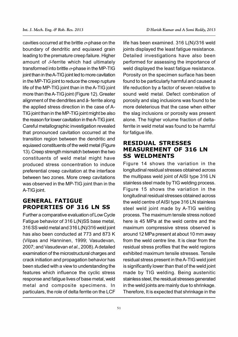
cavities occurred at the brittle -phase on theboundary of dendritic and equiaxed grainleading to the premature creep failure. Higheramount of -ferrite which had ultimatelytransformed into brittle -phase in the MP-TIGjoint than in the A-TIG joint led to more cavitationin the MP-TIG joint to reduce the creep rupturelife of the MP-TIG joint than in the A-TIG jointmore than the A-TIG joint (Figure 12). Greateralignment of the dendrites and ä- ferrite alongthe applied stress direction in the case of A-TIG joint than in the MP-TIG joint might be alsothe reason for lower cavitation in the A-TIG joint.Careful metallographic investigation revealedthat pronounced cavitation occurred at thetransition region between the dendritic andequiaxed constituents of the weld metal (Figure13). Creep strength mismatch between the twoconstituents of weld metal might haveproduced stress concentration to inducepreferential creep cavitation at the interfacebetween two zones. More creep cavitationswas observed in the MP-TIG joint than in theA-TIG joint.
GENERAL FATIGUEPROPERTIES OF 316 LN SSFurther a comparative evaluation of Low CycleFatigue behavior of 316 L(N)SS base metal,316 SS weld metal and 316 L(N)/316 weld jointhas also been conducted at 773 and 873 K(Vilpas and Hanninen, 1999; Vasudevan,2007; and Vasudevan et al., 2008). A detailedexamination of the microstructural charges andcrack initiation and propagation behavior hasbeen studied with a view to understanding thefeatures which influence the cyclic stressresponse and fatigue lives of base metal, weldmetal and composite specimens. Inparticulars, the role of delta ferrite on the LCF
life has been examined. 316 L(N)/316 weldjoints displayed the least fatigue resistance.Detailed investigations have also beenperformed for assessing the importance ofweld displayed the least fatigue resistance.Porosity on the specimen surface has beenfound to be particularly harmful and caused alife reduction by a factor of seven relative tosound weld metal. Defect combination ofporosity and slag inclusions was found to bemore deleterious that the case when eitherthe slag inclusions or porosity was presentalone. The higher volume fraction of delta-ferrite in weld metal was found to be harmfulfor fatigue life.
RESIDUAL STRESSESMEASUREMENT OF 316 LNSS WELDMENTSFigure 14 shows the variation in thelongitudinal residual stresses obtained acrossthe multipass weld joint of AISI type 316 LNstainless steel made by TIG welding process.Figure 15 shows the variation in thelongitudinal residual stresses obtained acrossthe weld centre of AISI type 316 LN stainlesssteel weld joint made by A-TIG weldingprocess. The maximum tensile stress noticedhere is 45 MPa at the weld centre and themaximum compressive stress observed isaround 12 MPa present at about 10 mm awayfrom the weld centre line. It is clear from theresidual stress profiles that the weld regionsexhibited maximum tensile stresses. Tensileresidual stress present in the A-TIG weld jointis significantly lower than that of the weld jointmade by TIG welding. Being austeniticstainless steel, the residual stresses generatedin the weld joints are mainly due to shrinkage.Therefore, It is expected that shrinkage in the

52
Int. J. Mech. Eng. & Rob. Res. 2013 D Harish Kumar and A Somi Reddy, 2013
weld metal of A-TIG welded joint should be lessand hence the residual stress value comparedto that of the multipass weld where theshrinkage should be more due to higher weld
metal volume. Differences in the weld metalvolume was due to the fact that the A-TIG weldjoint was made in single pass without filler metaladdition while the multipass TIG weld was made
Figure 14: Surface/Sub-Surface Residual Stress Profile Across the Weld Joint Madeby TIG Welding Measured Using an Ultrasonic Technique
Figure 15: Surface/Sub-Surface Residual Stress Profile Across the Weld Joint Madeby A-TIG Welding Measured Using an Ultrasonic Technique

53
Int. J. Mech. Eng. & Rob. Res. 2013 D Harish Kumar and A Somi Reddy, 2013
using 6 passes with filler metal addition in V-groove joint configuration. The benefit in termsof the reduction in the residual stresses in A-TIG weld joint is very significant. There was nodistortion in the joint made A-TIG welding whileangular distortion was evident in the joint madeby TIG welding. The compressive residualstresses are smaller and their profiles arecomparable in both the weld joints.
CONCLUSIONVery vaguely studied on the residual stressmeasurements of weldments fabricated bylaser welding and hybrid welding. Activated fluxTIG welding showed considerable reductionon the residual stresses as comparative MP-TIG welding. 316 LN SS was greatly acceptedas a candidate material for structuralapplications of nuclear service due to its betterin service properties both room temparatureas well as in service properties. Both the jointspossessed lower creep rupture strength thanthe base metal. The A-TIG joint had highercreep rupture strength than the MP-TIG joint.Failure in the weld joints occurred in the weldmetal. Progressive localization of creepdeformation in the weld metal led to thepremature failure of the joints in the weld metal.Higher amount of ä- ferrite in the MP-TIG jointthan the A-TIG joint induced higher creepdeformation rate and higher accumulation ofcreep damage in MP-TIG joint to reduce creeprupture strength.
ACKNOWLEDGEMENTThe authors wish to acknowledge the kind helpof Prof. K Ashok Reddy, Principal, KITS Warangaland scientists of IGCAR, Kalpakkam, during theprogress of this report. One of the authors wishto acknowledge the encouragement of Prof. M
R Seshadri and Prof. S K Biswas of I.I.Sc.,Bangalore for promoting his research throughouthis career. Shri Harish Kumar wish toacknowledge the encouragement of Prof. PVenkateshwarlu, Principal of S R Engineeringcollege, Ananthsagar, Warangal. He is alsograteful to Dr. K Guru Raj, HOD of MechanicalEngineering, KITS, Warangal for hisencouragement in pursuing the research on laserwelding. The authors are grateful to themanagement of KITS Warangal, VITSKarimnagar and S R Engineering College forgiving permission to present their paper at the2010 I.I.W. seminar
REFERENCES1. Bandy R and Van Rooyen D (1985),
Corrosion, Vol. 41, p. 228.
2. Bhanu Sankara Rao K et al. (1993),“Creep-Fatigue Interaction Behaviour ofType 308 Stainless Steel Weld Metal andType 304 Stainless Steel Base Metal”, Intl.J. Fatigue, Vol. 15, pp. 221-229.
3. Bhanu Sankara Rao K et al. (1994),“Influence of Weld Discontinuities onStrain Controlled Fatigue Behaviour of308 Stainless Steel Weld Metal”, J.Engineering Materials and Technology,Vol. 116, pp. 193-199.
4. Borland J C (1960), “Generalized Theoryof Super-Solidus Cracking in Welds (andCastings)”, Br. Weld. J., Vol. 7, pp. 508- 512.
5. Borland J C and Younger R N (1960),“Some Aspects of Cracking in Welded Cr-Ni Austenitic Steels”, Br. Weld. J., Vol. 7,pp. 22-59.
6. Briant C L, Mulford R A and Hall E L(1982), Corrosion, Vol. 38, p. 468.
54
Int. J. Mech. Eng. & Rob. Res. 2013 D Harish Kumar and A Somi Reddy, 2013
7. Brooks J A (1974), “Effect of AllyModifications on HAZ Cracking of A-286Stainless Steels”, Weld. J., Vol. 53,pp. 517s-523s.
8. Dundas H J and Bond A P (1975), NACECorrosion, Vol. 75, Preprint No. 159.
9. Dutta R S, De P K and Gadiyar H S(1993), Corrosion Science, Vol. 34, p. 51.
10. Eckenrod J J and Kovach C W (1979a),“Effect of Nitrogen on the Sensitization,Corrosion and Mechanical Properties of18Cr-8Ni Stainless Steels”, in C RBrinkman and H W Garvin (Eds.), ASTMSTP, Vol. 679, pp. 17-41.
11. Eckenrod J J and Kovach C W (1979b),“ASTM STP 679, American Society forTesting of Metals”, p. 17, Philadelphia,PA.
12. Folkhard E (1988), “Welding Metallurgyof Stainless Steels”, Springer Verlag, NewYork.
13. Garner A (1977), Pulp and Paper IndustryCorrosion Problems, Vol. 2, NACE.
14. Gill T P S, Gnanamoorthy J B andPadmanabhan K A (1987), Corrosion,Vol. 43, p. 208.
15. Goodwin G M (1988), “The Effects of HeatInput and Weld Process on Hot Crackingin Stainless Steel”, Weld. J., Vol. 67,pp. 88s-94s.
16. Hull F C (1967a), Welding Journal,Vol. 46, p. 399s.
17. Hull F C (1967b), “The Effect of and—Ferrite on the Hot Cracking of StainlessSteel”, Weld. J., Vol. 46, pp. 399s-409s.
18. Jargelius R and Vallin T (1986),“Proceedings of the Tenth ScandinavianCorrosion Congress”, Stockholm, p. 181.
19. Kamachi Mudali U, Dayal R K,Gnanamoorthy J B and Rodriquez P(1996), Materials Transactions of theJapan Institute of Metals, Vol. 37, p. 1568.
20. Kwok C T, Fong S L, Cheng F T and ManH C (2006), “Pitting and Galvanic CorrosionBehavior of Laser-Welded StainlessSteels”, Journal of Materials, ProcessingTechnology, Vol. 176, p. 168-178.
21. Laha K, Kyono J, Sasaki T, Kishimoto Sand Shinya N (2005), “Improved CreepStrength and Creep Ductility of Type 347Austenitic Stainless Steel Through the SelfHealing Effect of Boron for CreepCavitation”, Metallurgical and MaterialsTransactions A, Vol. 36A, February, p. 399.
22. Laha K, Kyono J and Shinya N (2007),“Some Chemical and MicrostructuralFactors Influencing Creep CavitationResistance of Austenitic Stainless Steels”,Philosophical Magazine, Vol. 87, No. 17,pp. 2483-2505.
23. Manning P E, Lyrnan C E and DuquetteD J (1980), Corrosion, Vol. 36, p. 246.
24. Mathew M D, Latha S, Bhanu SankaraRao K (2007), “An Assessment of CreepStrength Reduction Factor for 316 L(N) SSWelds”, Materials Science andEngineering A, Vol. 456, pp. 28-34.
25. Matsuda F, Nakagawa H, Katayama Sand Arata Y (1982), “A SolidificationCrack Susceptibility in Weld Metals ofFully Austenitic Stainless Steels (ReportVI) – Effect of La or REM Addition on
55
Int. J. Mech. Eng. & Rob. Res. 2013 D Harish Kumar and A Somi Reddy, 2013
Solidification Crack Resistanc”, Trans.Jpn. Weld. Res. Inst., Vol. 11, pp. 79-94.
26. Medovar I (1954), “On the Nature of WeldHot Cracking”, Avtomatich. Svark, Vol. 7,pp. 12-28.
27. Menon R and Kotecki D J (1989),“Literature Review – Nitrogen in StainlessSteel Weld Metal”, WRC Bull., No. 389,pp. 142-161.
28. Mishra M P, Borgstedt H U, Mathew M D,Mannan S L and Rodriguez P (1997),“A Comparative Study of Creep RuptureBehavior of Modified 316 L(N) Base Metaland 316 L(N)/16-8-2-Weldment in Air andLiquid Sodium Environments”, Int. Journalof Pressure Vessels & Piping, Vol. 72,pp. 111-118.
29. Moskowitz (1967), American Society forTesting of Metals – STP, Vol. 418, p. 3.
30. Mozhi T A, Clark W A T and Wilde B E(1987), Corrosion Science, Vol. 27, p. 257.
31. Mozhi T A, Clark W A T, Nishimoto K,Johnson W B and MacDonald D D(1985), Corrosion, Vol. 41, p. 555.
32. Ogawa T, Aoki S, Sakamoto T and ZaizenT (1982), Welding Journal, Vol. 61, p. 139s.
33. Osozawa K and Okada N (1976),“Proceedings of the Conference on‘Passivity and Its Breakdown in Iron andIron-Base Alloys’”, p. 135, NACE,Houston.
34. Parvathavarthini N, Dayal R K andGnanamoorthy J B (1994), Journal ofNuclear Materials, Vol. 208, p. 251.
35. Pehlke R D and Elliott J F (1960), Trans.AIME, Vol. 218, pp. 1088-1101.
36. Pickering F B (1989), “Proceedings of the‘First International Conference on HighNitrogen Steels’ ‘HNS 88’”,in J Foct andA Hendry (Eds.), p. 10, The Institute ofMetals, Lille, France.
37. Stevens S M (1989), “Forms of Nitrogen inWeld Metal”, WRC Bull., No. 369, pp. 1-2.
38. Sasikala G, Mathew M D, Bhanu ShankaraRao K and Mannan S L (1999), “CreepDeformation and Fracture Behaviour of aNitrogen-Bearing Type 316 StainlessSteel Weld Metal”, Journal of nuclearMaterials, Vol. 273, pp. 257-264.
39. Shaikh H, George G, Schneider F,Mummert K and Shatak H S (2000),“Stress Corrosion Crack Growth Studieson Nitrogen Added AISI Type 316Stainless Steel and its Weld Metal inBoiling Acidif ied Sodium ChlorideSolution Using the Fracture MechanicsApproach”, Meterial and Corrosion,Vol. 51, p. 719-727.
40. Shankar V, Gill T P S, Mannan S L andSundaresan S (2000), “Criteria for HotCracking Evaluation in AusteniticStainless Steel Welds Using theLongitudinal Varestraint andTransvarestraint Tests”, Sci. Technol.Weld. Join, Vol. 5, pp. 91-97.
41. Simmons J W (1996), Material Scienceand Engineering, Vol. A207, p. 159.
42. Sindo Kou (1989), “Grain StructureDevelopment in the Fusion Zone”, in S ADavid and J M Vitele (Eds.), Recent Trendsin Welding Science and Technology,Vol. 89, International ConferenceProceedings, ASM International.

56
Int. J. Mech. Eng. & Rob. Res. 2013 D Harish Kumar and A Somi Reddy, 2013
43. Valsan M et al. (1995), “A Comparative
Evaluation of Low Cycle Fatigue Behavior
of Type 316 LN Base Metal, 316 Weld
Metal and 316 LN/316 Weld Joint”,
Metllurgical and Materials Transactions
A, Vol. 26 A, pp. 1207-1219.
44. Vasudevan M (2007), “Computational
and Experimental Studies on Arc Welded
Austenitic Stainless Steels”, Ph.D.
Thesis, Indian Institute of Technology,Chennai.
45. Vasudevan M, Bhaduri A K and BaldevRaj (2008), “Development and Evaluationof Activated Flux for TIG Welding of Type304LN and Type 316 LN Stainless Steel”,pp. 211-218, IIW-IC-2008, Chennai.
46. Vilpas M and Hanninen H (1999),Materials Science Forun, Vol. 603,pp. 318-320.
Related Documents