REPORT ON INDUSTRIAL TRAINING AT TATA MOTORS LIMITED, JAMSHEDPUR Study of Hydraulics, Scope of Energy Conservation, and Line Modernization of LP BIW line in CAB & COWL FACTORY Submitted by VEDANT PRUSTY Reg. No.: 120929210 DEPT.OF MECHATRONICS ENGINEERING MANIPAL INSTITUTE OF TECHNOLOGY (A constituent institution of Manipal University) July 2015

Study of Hydraulics, Scope of Energy Conservation, and Line Modernization of LP BIW line in CAB & COWL FACTORY
Apr 11, 2016
Report on Industrial Training at TATA MOTORS LIMITED, Jamshedpur.
"Study of Hydraulics, Scope of Energy Conservation, and Line Modernization of LP BIW line in CAB & COWL FACTORY"
Submitted by
VEDANT PRUSTY
Reg. No.: 120929210
DEPT.OF MECHATRONICS ENGINEERING, MIT Manipal
The Objectives of this project are as follows:
To study the LP BIW line at CAB and COWL Factory at TATA Motors Jamshedpur in total.
To understand in detail the overall production mechanism and products of the LP line.
To specifically study the hydraulics and related equipment being used in the line.
To spot possible areas of energy loss or reduction in efficiency in the overall hydraulic system.
To recommend changes to the hydraulics system for improving efficiency of line.
To explore scope of induction of PLC with SCADA for control of the line along with interfacing with the hydraulics and pneumatics.
Welcome message from author
This document is posted to help you gain knowledge. Please leave a comment to let me know what you think about it! Share it to your friends and learn new things together.
Transcript

REPORT ON
INDUSTRIAL TRAINING
AT
TATA MOTORS LIMITED, JAMSHEDPUR
Study of Hydraulics, Scope of Energy Conservation, and Line Modernization of
LP BIW line in CAB & COWL FACTORY
Submitted by
VEDANT PRUSTY
Reg. No.: 120929210
DEPT.OF MECHATRONICS ENGINEERING
MANIPAL INSTITUTE OF TECHNOLOGY (A constituent institution of Manipal University)
July 2015

Study of Hydraulics, Scope of Energy Conservation, and Line Modernization of LP BIW line in
CAB & COWL FACTORY July 2015
2 Vedant Prusty [email protected] TATA Motors, Jamshedpur
DECLARATION
I, the undersigned, declare that this project and record entitled, “Study of
Hydraulics, Scope of Energy Conservation, and Line Modernization of LP BIW
line in CAB & COWL FACTORY” is the result of my own research carried out
under the supervision of Mr. Ashim Kumar Dhar and Mr. Partha Das. It has not
been presented as a paper in any university and all source of material used for
this paper are duly acknowledged.
The account of the work done is as executed at TATA Motors LTD,
Jamshedpur.
Vedant Prusty
Reg. No. 120929210 Date
This is to certify that the above declaration made by the candidate is correct to
my best knowledge.
Mr. Ashim Kumar Dhar
Divisional Manager Date
Cab & Cowl
TATA Motors LTD, Jamshedpur
Mr. Partha Das
Manager Date
Maintenance
Cab & Cowl
TATA Motors LTD, Jamshedpur

Study of Hydraulics, Scope of Energy Conservation, and Line Modernization of LP BIW line in
CAB & COWL FACTORY July 2015
3 Vedant Prusty [email protected] TATA Motors, Jamshedpur
CONTENTS
Acknowledgements ............................................................................................... 4
Introduction ........................................................................................................... 5
INTERNATIONAL BUSINESS: ...................................................................... 6
SUBSIDIARIES: ............................................................................................... 7
RESEARCH &DEVELOPMENT: ................................................................... 7
SALIENT STATISTICS ................................................................................... 8
TRUCK DIVISION ..................................................................................... 10
ENGINE DIVISION .................................................................................... 10
H V AXLE Ltd. (HVAL) ............................................................................. 10
H V TRANSMISSIONS Ltd. (HVTL) ........................................................ 11
FORGE DIVISION ...................................................................................... 11
FOUNDRY DIVISION ................................................................................ 11
CONSTRUCTION EQUIPMENT DIVISION ............................................ 11
TATA MOTOR VEHICLE SPECIFICATION: .......................................... 13
TATA MOTOR VEHICLE VARIANTS: ................................................... 14
Objectives ............................................................................................................ 17
Hydraulics ........................................................................................................... 18
Hydraulic Systems .............................................................................................. 20
Pumps .................................................................................................................. 29
Hydraulic Actuators ............................................................................................ 41
Hydraulic Motors………………………………………………………………43
Valves .................................................................................................................. 45
Hydraulic Fluids .................................................................................................. 55
Scope improving line efficincy and energy conservation ................................... 60
Scope for PLC and SCADA ............................................................................... 61

Study of Hydraulics, Scope of Energy Conservation, and Line Modernization of LP BIW line in
CAB & COWL FACTORY July 2015
4 Vedant Prusty [email protected] TATA Motors, Jamshedpur
ACKNOWLEDGEMENTS
"...the beauty of the destination is half veiled and the fragrance of success half dull until the
traces of all those enlightening the path are left to fly with the wind spreading word of
thankfulness..."
I am grateful to my guide, Mr. Ashim Kumar Dhar for leading the path and encouraging me
to widen my horizons. Thank You Sir for letting me dig deep into exploring the direct
applications of Mechatronics at TATA Motors, Jamshedpur.
My heartfelt gratitude to Mr. Partha Das of Maintenance at TATA Motors for helping me
identify, select and decide over the subject and scope of this project. Despite his busy
schedule and constant calls to breakdowns, he took out time to patiently guide and nurture
this project.
Without the companionship of Mr. Satyam Sinha and Mr. Anubhav Verma, TATA and
Jamshedpur would not have happened!
Thanks to Satyam, I was here!
Thanks to Anubhav, I made the fullest of my time here!
This project would not have seen the light of day without the constant support of my family –
my parents and my sister.
Special thanks to Mr. Jayant Kumar, Mr. Johnson Matthews (Johnny), at MTC- TATA
Motors JSR, and Mr. Nava at Maintenance – TATA Motors, for their help and support.

Study of Hydraulics, Scope of Energy Conservation, and Line Modernization of LP BIW line in
CAB & COWL FACTORY July 2015
5 Vedant Prusty [email protected] TATA Motors, Jamshedpur
INTRODUCTION
Company:
TATA motor is India’s largest automobile company. It is the leader by far in commercial
vehicle, and the second largest in passenger car market with winning products in the compact,
midsize car, utility vehicle segments. The company is the world’s fifth largest medium and
heavy bus manufacturer. The company’s employees are guided by vision to be “best in the
products we deliver and best in our value system and ethics”.
Company was established in 1945, TATA motors present indeed cuts across the length and
breadth of India. Over 4 million TATA motor vehicle ply on Indian roads, since the first
rolled out in 1954. The company’s manufacturing base is spread across Jamshedpur, Pune,
Pantnagar, Sanand and Lucknow, supported by a nation-wide dealership, sales, services and
spare parts network comprising about 3,500 touch points. The company also has a strong auto
finance operation, Tata Motor Finance.
At the core of the company's approach to doing business is the Tata Business Excellence
Model. Incorporating sound business principles, like customer satisfaction, quality, attention
to detail, conservation of resources and protection of the environment, this model shapes the
way Tata Motors designs, manufactures and markets its products.
PRODUCTS:
The company’s main product lines are:
Utility vehicles: The Tata Sumo launched in 1994, the Tata Safari launched in 1998
and their variants.
Passenger Cars: The compact car Tata Indica launched in 1998, The mid-size Tata
indigo launched in 2004 in both petrol and diesel versions.
Small commercial vehicles: Company created a new segment in 2005 by launching
Tata Ace, India’s first indigenously developed mini-truck.
Light commercial vehicles: It includes Pickups, Trucks and buses ranging from 2T
GVB to 7.5T GVB.
Medium and Heavy commercial vehicles: this segment includes trucks, Dumpers and
multi-axle vehicles from 9T GVW to 40T GVW. Through Tata Daewoo Commercial

Study of Hydraulics, Scope of Energy Conservation, and Line Modernization of LP BIW line in
CAB & COWL FACTORY July 2015
6 Vedant Prusty [email protected] TATA Motors, Jamshedpur
Vehicle Company Limited, it now offers a range of high horsepower trucks ranging
from 220 HP to 400 Hp in dump truck, tractor-trailers mixers and cargo applications.
World Truck: It is Prima division of Tata motors.
Adopting the principle of Kaizen or continuous learning, the company is constantly
improving its standards. The versatile yet simple 5S approach to process improvement –
Sort, Straighten, Simplify and Standardize in a self discipline manner- is a way of life at
TATA MOTORS.
These principles help optimize various operations of the company and conserve precious
resources. By working closely with vendors and partners, at the design and manufacturing
stages, the company ensures that they too follow the same principles.
INTERNATIONAL BUSINESS:
Tata Motors, the first company from India's engineering sector to be listed in the New York
Stock Exchange (September 2004), has also emerged as an international automotive
company. While currently about 18% of its revenues are from international business, the
company's objective is to expand its international business, both through organic and
inorganic growth routes.
Over the years, the company has received more than 50 awards from the Government of India
for its exports initiatives. In 2004, it acquired the Daewoo Commercial Vehicle Company,
Korea's second largest truck maker. The rechristened Tata Daewoo Commercial Vehicle
Company has already begun to launch new products. In 2005, Tata Motors acquired a 21%
stake in Hispano Carrocera, a reputed Spanish bus and coach manufacturer, with an option to
acquire the remaining stake as well. Hispano's presence is being expanded in other markets.
In 2006, it formed a joint venture with the Brazil-based Marcopolo, a global leader in body-
building for buses and coaches to manufacture fully-built buses and coaches for India and
select international markets. In 2006, Tata Motors entered into joint venture with Thonburi
Automotive Assembly Plant Company of Thailand to manufacture and market the company’s
pickup vehicles in Thailand. The new plant of Tata Motors (Thailand) has begun production
of the Xenon pickup truck, with the Xenon having been launched in Thailand at the Bangkok
Motor Show 2008.
These acquisitions will further extend Tata Motors' international footprint, established
through exports since 1961. The company's commercial and passenger vehicles are already

Study of Hydraulics, Scope of Energy Conservation, and Line Modernization of LP BIW line in
CAB & COWL FACTORY July 2015
7 Vedant Prusty [email protected] TATA Motors, Jamshedpur
being marketed in several countries in Europe, Africa, the Middle East, South East Asia,
South Asia and Australia. It has assembly operations in Malaysia, Kenya, Bangladesh,
Ukraine, Russia, Spain and Senegal.
SUBSIDIARIES:
Through its subsidiaries, the company is engaged in engineering and automotive solutions,
construction equipment manufacturing, automotive vehicle components manufacturing and
supply chain activities, machine tools and factory automation solutions, high-precision
tooling and plastic and electronic components for automotive and computer applications, and
automotive retailing and service operations. Through subsidiaries and associate companies,
Tata Motors has operations in the UK, South Korea, Thailand and Spain. Among them is
Jaguar Land Rover, a business comprising the two iconic British brands that was acquired in
2008.
RESEARCH &DEVELOPMENT:
The foundation of the company's growth over the last 50 years is a deep understanding of
economic stimuli and customer needs, and the ability to translate them into customer-desired
offerings through leading edge R&D. The company's Engineering Research Centre (ERC), in
Pune which has 2000 scientists and engineers, was established in 1966. Tata Daewoo
Commercial Vehicle Company and Hispano Carrocera also have R&D establishments at
Gunsan in Korea and Zaragoza in Spain. These three facilities together enable the company
to share and access knowledge and technology for designing and developing world-class
products. Besides product development, R&D also focuses on environment-friendly
technologies in emissions and alternative fuels.

Study of Hydraulics, Scope of Energy Conservation, and Line Modernization of LP BIW line in
CAB & COWL FACTORY July 2015
8 Vedant Prusty [email protected] TATA Motors, Jamshedpur
SALIENT STATISTICS
TOTAL AREA OF JAMSHEDPUR : 1780 ACRES
TOTAL AREA OF WORKS : 580 ACRES
COVERED AREA OF WORKS : 217 ACRES
LENGTH OF ROADS INSIDE WORKS : 30 MILES
AREA OF COLONY : 1200 ACRES
POPULATION OF COLONY : 35000(APPROX.)
TEMPERATURE : 45.50 C (MAX)
: 6.70 C (MIN)
AVERAGE RAINFALL : 99 CM
LONGITUDE : 86.120 E
LATITUDE : 22.470 N
ALTITUDE : 159m above Sea Level
(TATANAGAR)
GEOGRAPHICAL LOCATION : JHARKHAND

Study of Hydraulics, Scope of Energy Conservation, and Line Modernization of LP BIW line in
CAB & COWL FACTORY July 2015
9 Vedant Prusty [email protected] TATA Motors, Jamshedpur
Tata motor owes its leading position in the Indian automobile industry to its strong focus on
indigenization. This focus has driven the company to set up world class manufacturing units
with state-of art technology. Every stage of product evaluation design, development,
manufacturing, assembly and quality control, is carried out meticulously. Its manufacturing
plants are situated at Jamshedpur, Pune, Sanand, Lucknow and Pantnagar.
The world class facility equipped with:
State of art equipment and assembly lines to produce trucks every 5 minutes
Over 200 models, ranging from multi-axle trucks, tractor-trailers, tippers,
mixers and special application vehicles, catering to civilian and defense
requirements.
3D visualization of new models.
Engine assembly shop.
Modern testing facility.
The plant consist a world class engineering & research centre. The centre is responsible for
the conceptualization and integration of TATA motors current and future truck range.
The state-of-of-the art engine factory manufacturing the TATA 697/497 naturally aspirated
and turbo charged engines, with a supply capacity of 200 engines per day.
The vehicle factory main assembly line rolls out one truck every 5 minute. Two other lines
are dedicated to the Prima range, multi axle special purpose vehicles.
The chassis frames are supplied the frame factory, which is equipped with a 5000 ton
siempelkamp press to manufacture upto 6.2 meter wheel base.
The Cab & Cowl Factory is equipped with an automated centralized paint shop with a
provision for metallic painting and centralized trim lines which improve logistic flow.
It has state-of-the-art manufacturing facilities for making all major axle components such as
Front Axle Beam, Stub Axles, Front & Rear Wheel Hubs, Differential, Axle Gears (Crown
Wheel, Pinion, and Bevel Gear & Shaft Gear), Banjo Axle Beam, Swivel Heads, and
Constant Velocity Shafts etc.

Study of Hydraulics, Scope of Energy Conservation, and Line Modernization of LP BIW line in
CAB & COWL FACTORY July 2015
10 Vedant Prusty [email protected] TATA Motors, Jamshedpur
VARIOUS DIVISIONS OF TATA MOTORS
TRUCK DIVISION
The Truck division is the place where the final chassis of the automobile gets assembled.
This is fed by divisions like the Engine Division with aggregates of engine, axles, steering
and gearbox and also the forge division, which supplies the spring leaves for mounting axles
on the chassis.
The frame or the load carrying structure is made in the frame shop located in this division and
the cowl/cab types are provided by the cab and cowl shop which uses modern carbon dioxide
and spot welding techniques for fabrication of the cabs and cowls.
ENGINE DIVISION
Engine Division is involved in manufacture of engine. Raw materials to this division come in
the form of castings like the cylinder head, block, clutch housing, or forging like crankshaft,
con rods.
Its manufactured components are routed through either engine assembly or gearbox
assembly. The gearbox, after assembly, finds its way to engine assembly where ultimately,
the engine, complete gear box is assembled on AGVs (Automatic Guided Vehicles) and then
sent for testing on Saj-Froude. Electronic test beds, where the engine is checked for load
performance and speed and smoke emission.
H V AXLE Ltd. (HVAL)
Axle division is located partially in the inner and partially outer complex. The manufacturing
activities of the front and rear axle, the propelled shaft and the steering gearbox, king pin
boring and pad hole drilling are the most critical operations performed in the axle.
Perhaps the most critical component being manufactured in this division is the steering
gearbox assembly. The machining operation like grinding and lapping are performed here.
The front axle and rear axle are assembled here on AGVs before they are sent over to truck
division for assembly on chassis.

Study of Hydraulics, Scope of Energy Conservation, and Line Modernization of LP BIW line in
CAB & COWL FACTORY July 2015
11 Vedant Prusty [email protected] TATA Motors, Jamshedpur
H V TRANSMISSIONS Ltd. (HVTL)
Transmission division is located partially in the inner complex. The manufacturing of the
steering gearbox, king pin boring and pad hole drilling are the most critical operations
performed in the transmission.
Perhaps the most critical component being manufactured in this division is the steering
gearbox assembly. The machining operation like grinding and lapping are performed here.
The transmission system is assembled here on AGVs before they are sent over to truck
division for assembly on chassis.
FORGE DIVISION
The Forge is divided between an inner and outer complex. A variety of forging like
camshaft, front axle, stub-axle, con rod, pitman arm, bevel gears, crown wheel blank are
being produced in this division.
The Forge (outer complex) produces the front axle and the crank shaft on fully automated
Kurimoto and Nissei lines respectively. The spring shop in this division produces spring
leaves (about 130 sets per day) which are sent over to the truck division for mounting the
axles on the frame.
FOUNDRY DIVISION
The Foundry division caters to the requirement of both the automobile and Excavators
castings. From the thin-walled to the heavily cored casting the foundry of TATA MOTORS
can boast to be one of the most advanced captive foundries, producing castings by green sand
molding process. The castings are of alloyed and unalloyed cast/Grey iron, spheroid graphite
and low carbon and alloy steels.
CONSTRUCTION EQUIPMENT DIVISION
Excavators division has started making of mechanical excavators and cranes in collaboration
with M/s Harnischfeger Crop. (USA).
The manufacturing facilities include fabrication facilities typically carbon dioxide welding,
are available for fabrication of the frame, car-body, book etc. of the excavators.
INTRODUCTION TO THE CAB AND COWL FACTORY

Study of Hydraulics, Scope of Energy Conservation, and Line Modernization of LP BIW line in
CAB & COWL FACTORY July 2015
12 Vedant Prusty [email protected] TATA Motors, Jamshedpur
Truck III division of TATA MOTORS comprises of basically of three parts, namely, Painting
i.e. CPS (Centralized Paint Shop), Fitment i.e. CFL (Centralized Fitment Line) & Fabrication
i.e. LP Fabrication Line, SFC Cab/Cowl Fabrication Line, Heavy Cab/Cowl Fabrication Line
&Tilt Cab Fabrication Line,prima.
The Cab & Cowl Factory Equipped with an automated Centralized paint Shop with a
provision for metallic painting and centralized trim lines, which help to improve logistics
flow.
CPS paints all the models of Cabs & Cowls that are being produced in TATA MOTORS. The
capacity of CPS is 520 jobs per day. Every three minutes a job is rolled out of CPS. The
colors painted here are golden brown, blue moon, arctic white, ruby red etc. The jobs are
completely automated here including spray painting. The paint shop has striking features

Study of Hydraulics, Scope of Energy Conservation, and Line Modernization of LP BIW line in
CAB & COWL FACTORY July 2015
13 Vedant Prusty [email protected] TATA Motors, Jamshedpur
such as two color lines on a BIW, electro dip coding, complete robotic painting, power & free
conveyors and a single point dispatch.
CFL consists of fitment lines such as LP Cab, SFC
Cab/Cowl & 1109/713 cab & 2516 Heavy Cab
fitment line. Their capacities are 55, 65 & 30
cabs/shift respectively. The fitment lines have
striking features such as a continuous VFD
conveyor, dedicated trolleys, bins and pallets for
sheet metal fitment and provision of translucent
sheets for natural light and illumination in shop.
1109/713 fabrication line fabricates two models that are 1109 and 713 (military truck). There
are 13 stations on the WBL and 8 fixed stations, which are for finishing. Maximum capacity
of 1109 line is 55 per shift. Successful line balancing KAIZEN have been done for 55, 45, 36
& 25 cabs per shift. Partial success has been achieved for 18 cabs/shift lines balancing. The
fabrication lines have striking features such as a walking beam line for LP and 1109
fabrication lines, lift and carry conveyor for WORLD TRUCK line and MIG and spot
welding robots in the WORLD TRUCK line.
Cab and Cowl Factory supplies cabin bodies to the chassis assembly lines in Jamshedpur
itself, LP Cowls to the Lucknow branch, 1109/703 Cabs & aggregates to the vehicle factory
at Jabalpur and Cabins to spares parts & exports.
TATA MOTOR VEHICLE SPECIFICATION:
Each Tata Motor vehicle has a specific denotation consisting of four digits, let’s say XXYY:
XX- Denotes the tonnage capacity of the truck as gross vehicle weight (GVT).
YY- This no. multiplied by 10 denotes the brake horse power (BHP) the vehicle engine has.
For example-
2516 - VEHICLE SPECIFICATION
G.V.W. = 25 TONS
BHP = 16*10 = 160
3516- VEHICLE SPECIFICATION
G.V.W. = 35 TONS
BHP = 16*10 = 160

Study of Hydraulics, Scope of Energy Conservation, and Line Modernization of LP BIW line in
CAB & COWL FACTORY July 2015
14 Vedant Prusty [email protected] TATA Motors, Jamshedpur
TATA MOTOR VEHICLE VARIANTS:
LP:
LP 2515
LP 1613
LP 1510
LPO 1510
LPO 1512
LPO 1316L HD
LPO W/O FACE
SFC
COWL:
SE CMVR 1613
SE TC 1613
SK CMVR CAB POST 1613
SK TC CAB POST 1613
CAB:
SK 1613
CMVR CAB SK 1613
TC CAB SA 1212
CAB SD 1015 FATROLE
HEAVY CAB:
LPS 3516 SLEEPER CAB
LPK 2516 N/S CAB
LPT 2516 COWL
TILT CAB:
LPK 1613 NS TILT CAB
LPA 713 CAB
LPT 1613 SL TILT CAB
LPT 1618 LHD CAB WITH AC
World Truck :

Study of Hydraulics, Scope of Energy Conservation, and Line Modernization of LP BIW line in
CAB & COWL FACTORY July 2015
15 Vedant Prusty [email protected] TATA Motors, Jamshedpur
Sleeper
Non Sleeper
Sleeper M0
1.FAT CAB (minisuma project for indian army):
This cab is a transformation of heavy cab with improved aerodynamics.
Fat cab is basically used in heavy trucks. This cab is widely used for military trucks
now a day’s use. The name was given on the basis of its appearance.
2.Tilt Cab:
Tilt cab is generally used in light duty trucks. In tilt cab, cab is fitted above the
engine. Basically tilt cab got its name because it can tilt by an angle from the front
with the help of casting cup.It provides an advantage to the operator to be subjected
easily to the engine while maintenance

Study of Hydraulics, Scope of Energy Conservation, and Line Modernization of LP BIW line in
CAB & COWL FACTORY July 2015
16 Vedant Prusty [email protected] TATA Motors, Jamshedpur
3.SEMI FORWARD CHASSIS (SFC):
In semi forward chassis cab design the cab is so designed that the driver sits behind
the engine. It is one of the basic models of cab design by TATA motor.
4.Fully Forward (LT):
In the fully forward cab design allows the passenger area to be much larger than
general practice. In road vehicle design, Cab forward, also known as Cab-
over, COE (Cab over Engine), or forward control, is a body style of truck or van that
has a vertical front or "flat face", with the cab sitting above the front axle. This body
design allows for a more compact configuration.in this the driver sits in between the
engine and the cab door.

Study of Hydraulics, Scope of Energy Conservation, and Line Modernization of LP BIW line in
CAB & COWL FACTORY July 2015
17 Vedant Prusty [email protected] TATA Motors, Jamshedpur
OBJECTIVES
The Objectives of this project are as follows:
To study the LP BIW line at CAB and COWL Factory at TATA Motors Jamshedpur
in total.
To understand in detail the overall production mechanism and products of the LP line.
To specifically study the hydraulics and related equipment being used in the line.
To spot possible areas of energy loss or reduction in efficiency in the overall
hydraulic system.
To recommend changes to the hydraulics system for improving efficiency of line.
To explore scope of induction of PLC with SCADA for control of the line along with
interfacing with the hydraulics and pneumatics.
Figure 1: The LP BIW Line

Study of Hydraulics, Scope of Energy Conservation, and Line Modernization of LP BIW line in
CAB & COWL FACTORY July 2015
18 Vedant Prusty [email protected] TATA Motors, Jamshedpur
HYDRAULICS
Hydraulics is the science of transmitting force and/or motion through the medium of
Figure 2
a confined liquid. In a hydraulic device, power is transmitted by pushing on a confined
liquid. Figure 2 shows a simple hydraulic device. The transfer of energy takes place because
a quantity of liquid is subject to pressure. To operate liquid-powered systems, the operator
should have knowledge of the basic nature of liquids. This chapter covers the properties of
liquids and how they act under different conditions.
There is a major difference between a gas and a liquid. Liquids are incompressible. When a confined
liquid is pushed on, pressure builds up. The pressure is still transmitted equally throughout the
container. The fluid's behavior makes it possible to transmit a push through pipes, around corners, and
up and down. A hydraulic system uses a liquid
Pressure can be created by squeezing or pushing on a confined fluid only if there is a
resistance to flow. The two ways to push on a fluid are by the action of a mechanical pump or
by the weight of the fluid. An example of pressure due to a fluid's weight would be in an
ocean's depths. The water's weight creates the pressure, which increases or decreases,
depending on the depth.

Study of Hydraulics, Scope of Energy Conservation, and Line Modernization of LP BIW line in
CAB & COWL FACTORY July 2015
19 Vedant Prusty [email protected] TATA Motors, Jamshedpur
Force: The relationship of force, pressure, and area is as follows:
F = PA
where—
F = force, in pounds
P = pressure, in psi
A = area, in square inches
Pascal's Law. Blaise Pascal formulated the basic law of hydraulics in the mid 17th century.
He discovered that pressure exerted on a fluid acts equally in all directions. His law states
that pressure in a confined fluid is transmitted undiminished in every direction and acts with
equal force on equal areas and at right angles to a container's walls.
Flow: Flow is the movement of a hydraulic fluid caused by a difference in the pressure at two
points. In a hydraulic system, flow is usually produced by the action of a hydraulic pump—a
device used to continuously push on a hydraulic fluid. The two ways of measuring flow are
velocity and flow rate.
a. Velocity- Velocity is the average speed at which a fluid's particles move past a given point,
measured in feet per second (fps). Velocity is an important consideration in sizing the
hydraulic lines that carry a fluid between the components.
b. Flow Rate- Flow rate is the measure of how much volume of a liquid passes a point in a
given time, measured in gallons per minute (GPM). Flow rate determines the speed at which
a load moves and, therefore, is important when considering power.
Heat Energy and Friction
Heat energy is the energy a body possesses because of its heat. Kinetic energy and heat
energy are dynamic factors. Pascal's Law dealt with static pressure and did not include the
friction factor. Friction is the resistance to relative motion between two bodies. When liquid
flows in a hydraulic circuit, friction produces heat. This causes some of the kinetic energy to
be lost in the form of heat energy.
Although friction cannot be eliminated entirely, it can be controlled to some extent. The three
main causes of excessive friction in hydraulic systems are—
• Extremely long lines.

Study of Hydraulics, Scope of Energy Conservation, and Line Modernization of LP BIW line in
CAB & COWL FACTORY July 2015
20 Vedant Prusty [email protected] TATA Motors, Jamshedpur
• Numerous bends and fittings or improper bends.
• Excessive velocity from using undersized lines.
HYDRAULIC SYSTEMS
A hydraulic system contains and confines a liquid in such a way that it uses the laws
governing liquids to transmit power and do work. The oil reservoir (sump or tank) usually
serves as a storehouse and a fluid conditioner. Filters, strainers, and magnetic plugs condition
the fluid by removing harmful impurities that could clog passages and damage parts. Heat
exchanges or coolers often are used to keep the oil temperature within safe limits and prevent
deterioration of the oil. Accumulators, though technically sources of stored energy, act as
fluid storehouses.
Advantages of Hydraulic Systems
The advantages of hydraulic systems over other methods of power transmission are—
• Simpler design. In most cases, a few pre-engineered components will replace complicated
mechanical linkages.
• Flexibility. Hydraulic components can be located with considerable flexibility. Pipes and
hoses in place of mechanical elements virtually eliminate location problems.
• Smoothness. Hydraulic systems are smooth and quiet in operation. Vibration is kept to a
minimum.
• Control. Control of a wide range of speed and forces is easily possible.
• Cost. High efficiency with minimum friction loss keeps the cost of a power transmission at
a minimum.
• Overload protection. Automatic valves guard the system against a breakdown from
overloading.
Disadvantages of Hydraulic Systems

Study of Hydraulics, Scope of Energy Conservation, and Line Modernization of LP BIW line in
CAB & COWL FACTORY July 2015
21 Vedant Prusty [email protected] TATA Motors, Jamshedpur
The main disadvantage of a hydraulic system is maintaining the precision parts when they are
exposed to bad climates and dirty atmospheres. Protection against rust, corrosion, dirt, oil
deterioration, and other adverse environment is very important.
Figure 3: open-center system with a flow divider.
A flow divider takes the volume of oil from a
pump and divides it between two functions.
With this system, a pump must be large enough
to operate all the functions simultaneously. It
must also supply all the liquid at the maximum
pressure of the highest function, meaning large
amounts of HP are wasted when operating only
one control valve.
LP Line Hydraulic System:
The LP BIW Line uses an extensive hydraulic system to operate the scissor lift mechanism
and the inversion mechanism of all its stations. All Scissor lifts are powered by a common
power pack. The inversion mechanisms have their own respective Power Packs and
reservoirs.
Figure 4: Inversion Mechanism and Scissor Lift respectively
Reservoir

Study of Hydraulics, Scope of Energy Conservation, and Line Modernization of LP BIW line in
CAB & COWL FACTORY July 2015
22 Vedant Prusty [email protected] TATA Motors, Jamshedpur
A reservoir stores a liquid that is not being used in a hydraulic system. It also allows gases to
be expelled and foreign matter to settle out from a liquid.
a. Construction. A properly constructed reservoir should be able to dissipate heat from the
oil, separate air from the oil, and settle out contaminates that are in it. Reservoirs range in
construction from small steel stampings to large cast or fabricated units. The large tanks
should be sandblasted after all the welding is completed and then flushed and steam cleaned.
Doing so removes welding scale and scale left from hot-rolling the steel. The inner surface
then should be sealed with a paint compatible with the hydraulic fluid. Nonbleeding red
engine enamel is suitable for petroleum oil and seals in any residual dirt not removed by
flushing and steam-cleaning.
b. Shape. Figure 7 shows some of the design features of a reservoir. It should be high and
narrow rather than shallow and broad. The oil level should be as high as possible above the
opening to a pump's suction line. This prevents the vacuum at the line opening from causing a
vortex or whirlpool effect, which would mean that a system is probably taking in air. Aerated
oil will not properly transmit power because air is compressible. Aerated oil has a tendency to
break down and lose its lubricating ability.
Figure 5

Study of Hydraulics, Scope of Energy Conservation, and Line Modernization of LP BIW line in
CAB & COWL FACTORY July 2015
23 Vedant Prusty [email protected] TATA Motors, Jamshedpur
Figure 6: Power Pack for inversion mechanism
c. Size. Reservoir sizes will vary. However, a reservoir must be large enough so that it has a
reserve of oil with all the cylinders in a system fully extended. An oil reserve must be high
enough to prevent a vortex at the suction line's opening. A reservoir must have sufficient
space to hold all the oil when the cylinders are retracted, as well as allow space for expansion
when the oil is hot.
A common-size reservoir on a mobile machine is a 20- or 30-gallon tank used with a 100-
GPM system. Many 10-GPM systems operate with 2- or 3-gallon tanks because these mobile
systems operate intermittently, not constantly. For stationary machinery, a rule of thumb is
that a reservoir’s size should be two to three times a pump’s output per minute.
A large size tank is highly
desirable for cooling. The large
surface areas exposed to the
outside air transfer heat from the
oil. Also, a large tank helps settle
out the contaminants and
separates the air by reducing
recirculation.

Study of Hydraulics, Scope of Energy Conservation, and Line Modernization of LP BIW line in
CAB & COWL FACTORY July 2015
24 Vedant Prusty [email protected] TATA Motors, Jamshedpur
d. Location. Most mobile equipment reservoirs are located above the pumps. This creates a
flooded-pump-inlet condition. This condition reduces the possibility of pump cavitation—a
condition where all the available space is not filled and often metal parts will erode. Flooding
the inlet also reduces the vortex tendency at a suction pipe's opening.
The location of a reservoir affects heat dissipation. Ideally, all tank walls should be exposed
to the outside air. Heat moves from a hot substance to a cold substance; heat transfer is
greatest when there is a large temperature difference. Reservoirs that are built into front-end
loader arms are very effective in transferring heat.
e. Ventilation and Pressurization. Most reservoirs are vented to the atmosphere. A vent
opening allows air to leave or enter the space above the oil as the level of the oil goes up or
down. This maintains a constant atmospheric pressure above the oil. A reservoir filter cap,
with a filter element, is often used as a vent.
Some reservoirs are pressurized, using a simple pressure-control valve rather than a vented
one. A pressure-control valve automatically lets filtered air into a tank but prevents air release
unless the pressure reaches a preset level. A pressurized reservoir takes place when the oil
and air in a tank expand from heat.
f. Line Connections. A pump suction and a tank's return lines should be attached by flanges
or by welded heavy-duty couplings. Standard couplings usually are not suitable because they
spread when welded. If a suction line is connected at the bottom, a coupling should extend
well above the bottom, inside the tank; residual dirt will not get in a suction line when a tank
or strainer is cleaned. A return line should discharge near a tank's bottom always below the
oil level. A pipe is usually cut at a 45-degree angle and the flow aimed away from a suction
line to improve circulation and cooling.

Study of Hydraulics, Scope of Energy Conservation, and Line Modernization of LP BIW line in
CAB & COWL FACTORY July 2015
25 Vedant Prusty [email protected] TATA Motors, Jamshedpur
Figure 7: Heat Exchangers/Intercoolers on return line
A baffle plate is used to separate a suction line from a return line. This causes the return oil to
circulate around an outer wall for cooling before it gets to the pump again. A baffle plate
should be about two-thirds the height of a tank. The lower corners are cut diagonally to allow
circulation. They must be larger in area than a suction line's cross section.
Otherwise the oil level between a return and a suction side might be uneven. Baffling also
prevents oil from sloshing around when a machine is moving. Many large reservoirs are
cross-baffled to provide cooling and prevent sloshing.
g. Maintenance. Maintenance procedures include draining and cleaning a reservoir. A tank
should have a dished bottom that is fitted with a drain plug at its lowest point; a plug fitting
should be flushed with the inside of a tank to allow for full drainage. On large tanks, access
plates may be bolted on the ends for easy removal and servicing. A reservoir should have a
sight gauge or dipstick for checking the oil level to prevent damage from lubrication loss.
The strainers on a pump's suction line may not require as much maintenance. However, an
element in a filter in a return line will require regular changing. Therefore, that filter should
not be inside a reservoir. When a reservoir is pressurized by compressed air, moisture can
become a maintenance problem. A tank should have a water trap for moisture removal; it
should be placed where it can be inspected daily.

Study of Hydraulics, Scope of Energy Conservation, and Line Modernization of LP BIW line in
CAB & COWL FACTORY July 2015
26 Vedant Prusty [email protected] TATA Motors, Jamshedpur
Figure 8: Power Pack and Reservoir of LP Line
Strainers and Filters
To keep hydraulic components performing correctly, the hydraulic liquid must be kept as
clean as possible. Foreign matter and tiny metal particles from normal wear of valves, pumps,
and other components are going to enter a system.
Strainers, filters, and magnetic plugs are used to remove foreign particles from a hydraulic
liquid and are effective as safeguards against contamination. Magnetic plugs, located in a
reservoir, are used to remove the iron or steel particles from a liquid.
a. Strainers. A strainer is the primary filtering system that removes large particles of foreign
matter from a hydraulic liquid. Even though its screening action is not as good as a filter's, a
strainer offers less resistance to flow. A strainer usually consists of a metal frame wrapped
with a fine-mesh wire screen or a screening element made up of varying thickness of
specially processed wire. Strainers are used to pump inlet lines where pressure drop must be
kept to a minimum.

Study of Hydraulics, Scope of Energy Conservation, and Line Modernization of LP BIW line in
CAB & COWL FACTORY July 2015
27 Vedant Prusty [email protected] TATA Motors, Jamshedpur
Figure 9: Hydraulic-system strainers
Figure 10 shows a strainer in three possible arrangements for use in a pump inlet line. If one
strainer causes excessive flow friction to a pump, two or more can be used in parallel.
Strainers and pipe fittings must always be below the liquid level in the tank.
b. Filters. A filter removes small foreign particles from a hydraulic fluid and is most effective
as a safeguard against contaminates. Filters are located in a reservoir, a pressure line, a return
line, or in any other location where necessary. They are classified as full flow or proportional
flow.
(1) Full-Flow Filter (Figure 11). In a full-flow filter, all the fluid entering a unit passes
through a filtering element. Although a full-flow type provides a more positive filtering
action, it offers greater resistance to flow, particularly when it becomes dirty. A hydraulic
liquid enters a full-flow filter through an inlet port in the body and flows around an element
inside a bowl. Filtering occurs as a liquid passes through the element and into a hollow core,
leaving the dirt and impurities on the outside of the element. A filtered liquid then flows from
a hollow core to an outlet port and into the
system.
F
i
g
u
r
e
1

Study of Hydraulics, Scope of Energy Conservation, and Line Modernization of LP BIW line in
CAB & COWL FACTORY July 2015
28 Vedant Prusty [email protected] TATA Motors, Jamshedpur
0: Full-flow Hydraulic Filter
A bypass relief valve in a body allows a liquid to bypass the element and pass directly
through an outlet port when the element becomes clogged. Filters that do not have a bypass
relief valve have a contamination indicator. This indicator works on the principle of the
difference in pressure of a fluid as it enters a filter and after it leaves an element. When
contaminating particles collect on the element, the differential pressure across it increases.
When a pressure increase reaches a specific value, an indicator pops out, signifying that the
element must be cleaned or replaced.
Figure 11 Filter on Return Line
(2) Proportional-Flow Filters
(Figure 12). This filter operates on the venturi principle
in which a tube has a narrowing throat (venturi) to
increase the velocity of fluid flowing through it. Flow
through a venturi throat causes a pressure drop at the
narrowest point. This pressure decrease causes a
sucking action that draws a portion of a liquid down
around a cartridge through a filter element and up into
a venturi throat. Filtering occurs for either flow
direction.
Figure 12: Proportional-flow Filter
Although only a portion of a liquid is filtered during
each cycle, constant recirculation through a system
eventually causes all of a liquid to pass through the
element.
Replace the element according to applicable
regulations and by doing the following:
• Relieve the pressure.

Study of Hydraulics, Scope of Energy Conservation, and Line Modernization of LP BIW line in
CAB & COWL FACTORY July 2015
29 Vedant Prusty [email protected] TATA Motors, Jamshedpur
• Remove the bowl from the filter’s body.
• Remove the filter element from the body, using a slight rocking motion.
• Clean or replace the element, depending on its type.
• Replace all old O-ring packings and backup washers.
• Reinstall the bowl on the body assembly. Do not tighten the bowl excessively; check the
appropriate regulations for specifications, as some filter elements require a specific torque.
• Pressurize the system and check the filter assembly for leaks.
Figure 13: Pressure Relief Valve and DCV on Power Pack
PUMPS
Hydraulic pumps convert mechanical energy from a prime mover (engine or electric
motor) into hydraulic (pressure) energy. The pressure energy is used then to operate an
actuator.
Pumps push on a hydraulic fluid and create flow.
Pump Classifications. All pumps create flow. They operate on the displacement principle.
Fluid is taken in and displaced to another point. Pumps that discharge liquid in a continuous
flow are non positive-displacement type. Pumps that discharge volumes of liquid separated
by periods of no discharge are positive-displacement type.

Study of Hydraulics, Scope of Energy Conservation, and Line Modernization of LP BIW line in
CAB & COWL FACTORY July 2015
30 Vedant Prusty [email protected] TATA Motors, Jamshedpur
a. Non positive-Displacement Pumps.
With this pump, the volume of liquid delivered for each cycle depends on the resistance
offered to flow. A pump produces a force on the liquid that is constant for each particular
speed of the pump. Resistance in a discharge line produces a force in the opposite direction.
When these forces are equal, a liquid is in a state of equilibrium and does not flow.
If the outlet of a non positive-displacement pump is completely closed, the discharge pressure
will rise to the maximum for a pump operating at a maximum speed. A pump will churn a
liquid and produce heat. Figure 15 shows a nonpositive-displacement pump. A water wheel
picks up the fluid and moves it.
b. Positive-Displacement Pumps.
With this pump, a definite volume of liquid is delivered for each cycle of pump operation,
regardless of resistance, as long as the capacity of the power unit driving a pump is not
exceeded. If an outlet is completely closed, either the unit driving a pump will stall or
something will break. Therefore, a positive-displacement-type pump requires a pressure
regulator or pressure-relief valve in the system.
Figure 14: Non Positive displacement pump
This pump not only creates flow, but it also backs it up. A sealed case around the gear traps
the fluid and holds it while it moves. As the fluid flows out of the other side, it is sealed
against backup. This sealing is the positive part of displacement. Without it, the fluid could
never overcome the resistance of the other parts in a system.

Study of Hydraulics, Scope of Energy Conservation, and Line Modernization of LP BIW line in
CAB & COWL FACTORY July 2015
31 Vedant Prusty [email protected] TATA Motors, Jamshedpur
Characteristics. The three contrasting characteristics in the operation of positive- and non
positive-displacement pumps are as follows:
• Non positive-displacement pumps provide a smooth, continuous flow; positive
displacement pumps have a pulse with each stroke or each time a pumping chamber opens to
an outlet port.
• Pressure can reduce a non positive pump’s delivery. High outlet pressure can stop any
output; the liquid simply recirculates inside the pump. In a positive displacement pump,
pressure affects the output only to the extent that it increases internal leakage.
• Non positive-displacement pumps, with the inlets and outlets connected hydraulically
cannot create a vacuum sufficient for self-priming; they must be started with the inlet line full
of liquid and free of air. Positive-displacement pumps often are self-priming when started
properly.
Performance. Pumps are usually rated according to their volumetric output and pressure.
Volumetric output (delivery rate or capacity) is the amount of liquid that a pump can deliver
at its outlet port per unit of time at a given drive speed, usually expressed in GPM or cubic
inches per minute.
Displacement. Displacement is the amount of liquid transferred from a pump’s inlet to its
outlet in one revolution or cycle. Displacement is either fixed or variable.
a. Fixed-Displacement Pump. In this pump, the GPM output can be changed only by varying
the drive speed. The pump can be used in an open-center system—a pump’s output has a
free-flow path back to a reservoir in the neutral condition of a circuit.
b. Variable-Displacement Pump. In this pump, pumping-chamber sizes can be changed.
The GPM delivery can be changed by moving the displacement control, changing the drive
speed, or doing both. The pump can be used in a closed-center system—a pump continues to
operate against a load in the neutral condition.

Study of Hydraulics, Scope of Energy Conservation, and Line Modernization of LP BIW line in
CAB & COWL FACTORY July 2015
32 Vedant Prusty [email protected] TATA Motors, Jamshedpur
Slippage. Slippage is oil leaking from a pressure outlet to a low-pressure area or back to an
inlet. A drain passage allows leaking oil to return to an inlet or a reservoir. Some slippage is
designed into pumps for lubrication purposes. Slippage will increase with pressure and as a
pump begins to wear.
Volumetric efficiency model for pump
The flow losses in pump depends on the factors like pressure difference, viscosity of the fluid
etc. which is based on the formula
Pumps may be classified according to the specific design used to create the flow of a liquid.
Most hydraulic pumps are either centrifugal, rotary, or reciprocating.
Gear Pumps. Gear pumps are external, internal, or lobe types.
External.
Figure 16 shows the operating principle of an external gear pump. It consists of a driving gear
and a driven gear enclosed in a closely fitted housing. The gears rotate in opposite directions
and mesh at a point in the housing between the inlet and outlet ports. Both sets of teeth
project outward from the center of the gears. As the teeth of the two gears separate, a partial
vacuum forms and draws liquid through an inlet port into chamber A. Liquid in chamber A is
trapped between the teeth of the two gears and the housing so that it is carried through two
separate paths around to chamber B. As the teeth again mesh, they produce a force that drives
a liquid through an outlet port.

Study of Hydraulics, Scope of Energy Conservation, and Line Modernization of LP BIW line in
CAB & COWL FACTORY July 2015
33 Vedant Prusty [email protected] TATA Motors, Jamshedpur
Figure 15: External Gear Pump
Internal.
Figure 17 shows an internal gear pump. The teeth of one gear project outward, while the teeth
of the other gear project inward toward the center of the pump. One gear wheel stands inside
the other.
The rotation of the internal gear by a shaft causes the external gear to rotate, since the two are
in mesh. Everything in the chamber rotates except the crescent, causing a liquid to be trapped
in the gear spaces as they pass the crescent. Liquid is carried from an inlet to the discharge,
where it is forced out of a pump by the gears meshing. As liquid is carried away from inlet
side of a pump, the pressure is diminished, and liquid is forced in from the supply source. The
size of the crescent that separates the internal and external gears determines the volume
delivery of this pump. A small crescent allows more volume of a liquid per revolution than a
larger crescent.

Study of Hydraulics, Scope of Energy Conservation, and Line Modernization of LP BIW line in
CAB & COWL FACTORY July 2015
34 Vedant Prusty [email protected] TATA Motors, Jamshedpur
Figure 16: Internal Gear Pump
Lobe. Figure 18 shows a lobe pump. It differs from other gear pumps because it uses lobed
elements instead of gears. The element drive also differs in a lobe pump. In a gear pump, one
gear drives the other. In a lobe pump, both elements are driven through suitable external
gearing.
Figure 17: Lobe Pump
Vane Pumps. In a vane-type pump, a slotted rotor
splined to a drive shaft rotates between closely fitted
side plates that are inside of an elliptical- or circular-
shaped ring. Polished, hardened vanes slide in and
out of the rotor slots and follow the ring contour by
centrifugal force. Pumping chambers are formed
between succeeding vanes, carrying oil from the inlet
to the outlet. A partial vacuum is created at the inlet
as the space between vanes increases. The oil is
squeezed out at the outlet as the pumping chamber’s size decreases.

Study of Hydraulics, Scope of Energy Conservation, and Line Modernization of LP BIW line in
CAB & COWL FACTORY July 2015
35 Vedant Prusty [email protected] TATA Motors, Jamshedpur
Figure 18: Vane Pump and Motor on Power Pack
The vane pump on the Power Pack for LP line has compensation for cavitation. Two
lines can be seen exiting the vane pump (refer circuit) . One line is the main outlet, while
the other line is connected to the out let line again further down the chain. This supplies
fluid at high pressure back to vane pump to reduce the possibility of cavitation and its
affects.
Because the normal wear points in a vane pump are the vane tips and a ring’s surface, the
vanes and ring are specially hardened and ground. A vane pump is the only design that has
automatic wear compensation built in. As wear occurs, the vanes simply slide farther out of
the rotor slots and continue to follow a ring’s contour. Thus efficiency remains high
throughout the life of the pump.
a. Characteristics. Displacement of a vane-type pump depends on the width of the ring and
rotor and the throw of the cam ring. Interchangeable rings are designed so a basic pump
converts to several displacements. Balanced design vane pumps all are fixed displacement.
An unbalanced design can be built in either a fixed- or variable-displacement pump.
Vane pumps have good efficiency and durability if operated in a clean system using the
correct oil. They cover the low to medium-high pressure, capacity, and speed ranges. Package
size in relation to output is small. A vane pump is generally quiet, but will whine at high
speeds.

Study of Hydraulics, Scope of Energy Conservation, and Line Modernization of LP BIW line in
CAB & COWL FACTORY July 2015
36 Vedant Prusty [email protected] TATA Motors, Jamshedpur
b. Unbalanced Vane Pumps.
In the unbalanced design, (Figure 20), a cam ring’s shape is a true circle that is on a different
centerline from a rotor’s. Pump displacement depends on how far a rotor and ring are
eccentric. The advantage of a true-circle ring is that control can be applied to vary the
eccentricity and thus vary the displacement. A disadvantage is that an unbalanced pressure at
the outlet is effective against a small area of the rotor’s edge, imposing side loads on the
shaft. Thus there is a limit on a pump’s size unless very large hearings and heavy supports are
used.
Figure 19: Unbalanced Vane Pump
c. Balanced Vane Pumps.
In the balanced design (Figure 21), a
pump has a stationary, elliptical cam ring
and two sets of internal ports. A pumping
chamber is formed between any two
vanes twice in each revolution. The two
inlets and outlets are 180 degrees apart.
Back pressures against the edges of a
rotor cancel each other.
Recent design improvements that allow high operating speeds and pressures have made this
pump the most universal in the mobile equipment field.
Figure 20: Balanced Vane Pump
d. Double Pumps. Vanetype double pumps
consist of two separate pumping devices.
Each is contained in its own respective housing,
mounted in tandem, and driven by a common
shaft. Each pump also has its own inlet and
outlet ports, which may be combined by using
manifolds or piping.

Study of Hydraulics, Scope of Energy Conservation, and Line Modernization of LP BIW line in
CAB & COWL FACTORY July 2015
37 Vedant Prusty [email protected] TATA Motors, Jamshedpur
Design variations are available in which both cartridges are contained within one body. An
additional pump is sometimes attached to the head end to supply auxiliary flow requirements.
Double pumps may be used to provide fluid flow for two separate circuits or combined for
flow requirements for a single circuit. Combining pump deliveries does not alter the
maximum pressure rating of either cartridge. Separate circuits require separate pressure
controls to limit maximum pressure in each circuit.
Piston Pumps. Piston pumps are either radial or axial.
Radial.
In a radial piston pump (Figure 22), the pistons are arranged like wheel spokes in a short
cylindrical block. A drive shaft, which is inside a circular housing, rotates a cylinder block.
The block turns on a stationary pintle that contains the inlet and outlet ports. As a cylinder
block turns, centrifugal force slings the pistons, which follow a circular housing. A housing’s
centerline is offset from a cylinder block’s centerline.
The amount of eccentricity between the two determines a piston stroke and, therefore, a
pump’s displacement.
Controls can be applied to change a housing’s location and thereby vary a pump’s delivery
from zero to maximum.
Figure 21: Simplified Radial Piston Pump
Axial Piston Pumps.
In axial piston pumps, the pistons stroke
in the same direction on a cylinder
block’s centerline (axially). Axial piston
pumps may be an in-line or angle design.
In capacity, piston pumps range from low
to very high. Pressures are as high as
5,000 psi, and drive speeds are medium to

Study of Hydraulics, Scope of Energy Conservation, and Line Modernization of LP BIW line in
CAB & COWL FACTORY July 2015
38 Vedant Prusty [email protected] TATA Motors, Jamshedpur
high. Efficiency is high, and pumps generally have excellent durability. Petroleum oil fluids
are usually required. Pulsations in delivery are small and of medium frequency. The pumps
are quiet in operation but may have a growl or whine, depending on condition.
Except for in-line pumps, which are compact in size, piston pumps are heavy and bulky.
There are three main varieties:- In-Line Pump, Wobble-Plate In-Line Pump, and Bent Axis
Axial Piston Pump.
Figure 22: In-Line Piston Pump
Figure 23: Bent-Axis Axial Piston Pump
Pump Operation. The following paragraphs address some of the problems that could occur
when a pump is operating:
a. Overloading. One risk of overloading is the danger of excess torque on a drive shaft.
Torque is circular force on an object. An increase in pressure/pump displacement will
increase the torque on a shaft if pump displacement/pressure remains constant. Often in a

Study of Hydraulics, Scope of Energy Conservation, and Line Modernization of LP BIW line in
CAB & COWL FACTORY July 2015
39 Vedant Prusty [email protected] TATA Motors, Jamshedpur
given package size, a higher GPM pump will have a lower pressure rating than a lower GPM
pump. Sometimes a field conversion to get more speed out of an actuator will cause a pump
to be overloaded. You may need a larger pump.
b. Excess Speed. Running a pump at too high a speed causes loss of lubrication, which can
cause early failure. If a needed delivery requires a higher drive speed than a pump's rating,
use a higher displacement pump. Excess speed also runs a risk of damage from cavitation.
c. Cavitation. Cavitation occurs where available fluid does not fill an existing space. It often
occurs in a pump’s inlet when conditions are not right to supply enough oil to keep an inlet
flooded. Cavitation causes the metal in an inlet to erode and the hydraulic oil to deteriorate
quicker. Cavitation can occur if there is too much resistance in an inlet’s line, if a reservoir’s
oil level is too far below the inlet, or if an oil’s viscosity is too high. It can also occur if there
is a vacuum or even a slight positive pressure at the inlet. A badly cavitating pump has oil
bubbles exploding in the void. The only way to be sure a pump is not cavitating is to check
the inlet with a vacuum gauge.
To prevent cavitation, keep the inlet clean and free of obstructions by using the correct length
of an inlet’s line with minimum bends. Another method is to charge an inlet. The easiest way
to do this is to flood it by locating the reservoir above the pump’s inlet. If this is not possible
and you cannot create good inlet conditions, use a pressurized reservoir. You can also use an
auxiliary pump to maintain a supply of oil to an inlet at low pressure. You could use a
centrifugal pump, but it is more common to use a positive-displacement gear pump with a
pressure-relief valve that is set to maintain the desired charging pressure.

Study of Hydraulics, Scope of Energy Conservation, and Line Modernization of LP BIW line in
CAB & COWL FACTORY July 2015
40 Vedant Prusty [email protected] TATA Motors, Jamshedpur
d. Operating Problems. Pressure loss, slow operation, no delivery, and noise are common
operating problems in a pump.
(1) Pressure Loss. Pressure loss means that there is a high leakage path in a system. A
badly worn pump could cause pressure loss. A pump will lose its efficiency gradually.
The actuator speed slows down as a pump wears. However, pressure loss is more
often caused by leaks somewhere else in a system (relief valve, cylinders, motors).
(2) Slow Operation. This can be caused by a worn pump or by a partial oil leak in a system.
Pressure will not drop, however, if a load moves at all. Therefore, hp is still being used and is
being converted into heat at a leakage point. To find this point, feel the components for
unusual heat.
(3) No Delivery. If oil is not being pumped, a pump—
• Could be assembled incorrectly.
• Could be driven in the wrong direction.
• Has not been primed. The reasons for no prime are usually improper start-up, inlet
restrictions, or low oil level in a reservoir.
• Has a broken drive shaft.
(4) Noise. If you hear any unusual noise, shut down a pump immediately. Cavitation noise is
caused by a restriction in an inlet line, a dirty inlet filter, or too high a drive speed.
Air in a system also causes noise. Air will severely damage a pump because it will not have
enough lubrication. This can occur from low oil in a reservoir, a loose connection in an inlet,
a leaking shaft seal, or no oil in a pump before starting. Also, noise can be caused by worn or
damaged parts, which will spread harmful particles through a system, causing more damage
if an operation continues.

Study of Hydraulics, Scope of Energy Conservation, and Line Modernization of LP BIW line in
CAB & COWL FACTORY July 2015
41 Vedant Prusty [email protected] TATA Motors, Jamshedpur
HYDRAULIC ACTUATORS
A hydraulic actuator receives pressure energy and converts it to mechanical force and
motion. An actuator can be linear or rotary. A linear actuator gives force and motion outputs
in a straight line. It is more commonly called a cylinder but is also referred to as a ram,
reciprocating motor, or linear motor. A rotary actuator produces torque and rotating motion.
It is more commonly called a hydraulic motor or motor.
Cylinders
A cylinder is a hydraulic actuator that is constructed of a piston or plunger that operates in a
cylindrical housing by the action of liquid under pressure. Figure 4-1 shows the basic parts of
a cylinder. A cylinder housing is a tube in which a plunger (piston) operates. In a ram-type
cylinder, a ram actuates a load directly. In a piston cylinder, a piston rod is connected to a
piston to actuate a load. An end of a cylinder from which a rod or plunger protrudes is a rod
end. The opposite end is a head end. The hydraulic connections
are a head-end port and a rod-end port (fluid supply).
a. Single-Acting Cylinder. This cylinder (Figure 4-1) only has a head-end port and is operated
hydraulically in one direction. When oil is pumped into a port, it pushes on a plunger, thus
extending it. To return or retract a cylinder, oil must be released to a reservoir.
A plunger returns either because of the weight of a load or from some mechanical force such
as a spring. In mobile equipment, flow to and from a single-acting cylinder is controlled by a
reversing directional valve of a single-acting type.
b. Double-Acting Cylinder. This cylinder
(Figure 25) must have ports at the head and rod
ends. Pumping oil into the head end moves a
piston to extend a rod while any oil in the rod
end is pushed out and returned to a reservoir.
To retract a rod, flow is reversed. Oil from a
pump goes into a rod end, and a head-end port

Study of Hydraulics, Scope of Energy Conservation, and Line Modernization of LP BIW line in
CAB & COWL FACTORY July 2015
42 Vedant Prusty [email protected] TATA Motors, Jamshedpur
is connected to allow return flow. The flow direction to and from a double-acting cylinder
can be controlled by a double-acting directional valve or by actuating a control of a reversible
pump.
Figure 24: Double Acting Cylinder
Other types include Differential Cylinder, Non-differential Cylinder, Ram-type cylinder
(includes Telescopic type), Piston Type Cylinder, Cushioned Cylinder, and Lockout
Cylinders.
Figure 25: Double Acting Cylinder of Inversion Mechanism

Study of Hydraulics, Scope of Energy Conservation, and Line Modernization of LP BIW line in
CAB & COWL FACTORY July 2015
43 Vedant Prusty [email protected] TATA Motors, Jamshedpur
Cushioned Cylinder
To slow an action and prevent shock at the end of a piston stroke, some actuating cylinders
are constructed with a cushioning device at
either or both ends of a cylinder. This
cushion is usually a metering device built
into a cylinder to restrict the flow at an
outlet port, thereby slowing down the
motion of a piston. Figure 27 shows a
cushioned actuating cylinder.
Figure 26: Cushioned Actuating Cylinder

Study of Hydraulics, Scope of Energy Conservation, and Line Modernization of LP BIW line in
CAB & COWL FACTORY July 2015
44 Vedant Prusty [email protected] TATA Motors, Jamshedpur
HYDRAULIC MOTORS
Hydraulic motors convert hydraulic energy into mechanical energy. In industrial hydraulic
circuits, pumps and motors are normally combined with a proper valving and piping to form a
hydraulic-powered transmission. A pump, which is mechanically linked to a prime mover,
draws fluid from a reservoir and forces it to a motor.
A motor, which is mechanically linked to the workload, is actuated by this flow so that
motion or torque, or both, are conveyed to the work. Figure 28 shows the basic operations of
a hydraulic motor.
Figure 27: Basic operation of a Hydraulic Motor
They are of Gear, Vane and Piston types, with constructions similar to Hydraulic Pumps.
Hydraulic transmissions may be used for applications such as a speed reducer, variable speed
drive, constant speed or constant torque drive, and torque converter. Some advantages a
hydraulic transmission has over a mechanical transmission is that it has—
• Quick, easy speed adjustment over a wide range while the power source is
operating at constant (most efficient) speed.
• Rapid, smooth acceleration or deceleration.
• Control over maximum torque and power.
• A cushioning effect to reduce shock loads.
• A smooth reversal of motion.

Study of Hydraulics, Scope of Energy Conservation, and Line Modernization of LP BIW line in
CAB & COWL FACTORY July 2015
45 Vedant Prusty [email protected] TATA Motors, Jamshedpur
VALVES
Valves are used in hydraulic systems to control the operation of the actuators. Valves
regulate pressure by creating special pressure conditions and by controlling how much oil
will flow in portions of a circuit and where it will go. The three categories of hydraulic valves
are pressure-control, flow- (volume-) control, and directional-control (see Figure 29). Some
valves have multiple functions, placing them into more than one category. Valves are rated
by their size, pressure capabilities, and pressure drop/flow.
Figure 28: Valves
Pressure-Control Valves
A pressure-control valve may limit or regulate pressure, create a particular pressure condition
required for control, or cause actuators to operate in a specific order. All pure pressure-
control valves operate in a condition approaching hydraulic balance. Usually the balance is
very simple: pressure is effective on one side or end of a ball, poppet, or spool and is opposed
by a spring. In operation, a valve takes a position where hydraulic pressure balances a spring
force. Since spring force varies with compression, distance and pressure also can vary.
Pressure-control valves are said to be infinite positioning.
This means that they can take a position anywhere between two finite flow conditions, which
changes a large volume of flow to a small volume, or pass no flow.

Study of Hydraulics, Scope of Energy Conservation, and Line Modernization of LP BIW line in
CAB & COWL FACTORY July 2015
46 Vedant Prusty [email protected] TATA Motors, Jamshedpur
Most pressure-control valves are classified as normally closed. This means that flow to a
valve's inlet port is blocked from an outlet port until there is enough pressure to cause an
unbalanced operation. In normally open valves, free flow occurs through the valves until they
begin to operate in balance. Flow is partially restricted or cut off. Pressure override is a
characteristic of normally closed-pressure controls when they are operating in balance.
Because the force of a compression spring increases as it lowers, pressure when the valves
first crack is less than when they are passing a large volume or full flow. The difference
between a full flow and cracking pressure is called override.
a. Relief Valves. Relief valves are the most common type of pressure-control valves.
The relief valves’ function may vary, depending on a system's needs. They can provide
overload protection for circuit components or limit the force or torque exerted by a linear
actuator or rotary motor.
The internal design of all relief valves is basically similar. The valves consist of two sections:
a body section containing a piston that is retained on its seat by a spring(s), depending on the
model, and a cover or pilot-valve section that hydraulically controls a body piston’s
movement. The adjusting screw adjusts this control within the range of the valves.
There are two types of relief valves- simple and compound.
Figure 29: Simple Relief Valve

Study of Hydraulics, Scope of Energy Conservation, and Line Modernization of LP BIW line in
CAB & COWL FACTORY July 2015
47 Vedant Prusty [email protected] TATA Motors, Jamshedpur
Figure 30: Compound Relief Valve
b. Pressure-Reducing Valves. These valves limit pressure on a branch circuit to a lesser
amount than required in a main circuit. For example, in a system, a branch-circuit pressure is
limited to 300 psi, but a main circuit must operate at 800 psi. A relief valve in a main circuit
is adjusted to a setting above 800 psi to meet a main circuit's requirements. However, it
would surpass a branch-circuit pressure of 300 psi. Therefore, besides a relief valve in a main
circuit, a pressure-reducing valve must be installed in a branch circuit and set at 300 psi.
Figure 32 shows a pressure reducing valve.
Figure 31: Pressure Reducing Valve
c. Sequence Valves.
Sequence valves control the
operating sequence between two
branches of a circuit. The valves
are commonly used to regulate
an operating sequence of two
separate work cylinders so that
one cylinder begins stroking
when the other completes
stroking. Sequence valves used in this manner ensure that there is minimum pressure equal to
its setting on the first cylinder during the subsequent operations at a lower pressure.

Study of Hydraulics, Scope of Energy Conservation, and Line Modernization of LP BIW line in
CAB & COWL FACTORY July 2015
48 Vedant Prusty [email protected] TATA Motors, Jamshedpur
Figure 32: Sequence Valve
d. Counterbalance Valves. A
counterbalance valve allows free flow
of fluid in one direction and maintains a
resistance to flow in another direction
until a certain pressure is reached. A
valve is normally located in a line
between a directional-control valve and
an outlet of a vertically mounted actuating cylinder, which supports weight or must be held in
position for a period of time. A counterbalance valve serves as a hydraulic resistance to an
actuating cylinder. For example, a counterbalance valve is used in some hydraulically
operated fork lifts. It offers a resistance to the flow from an actuating cylinder when a fork is
lowered. It also helps support a fork in the up position.
Figure 33: Counterbalance Valve
e. Pressure Switches.
Pressure switches are used in various applications
that require an adjustable, pressure-actuated
electrical switch to make or break an electrical
circuit at a predetermined pressure.
An electrical circuit may be used to actuate an
electrically controlled valve or control an electric
motor starter or a signal light. Figure 35 shows a
pressure switch.
Figure 34:
Pressure
Switch

Study of Hydraulics, Scope of Energy Conservation, and Line Modernization of LP BIW line in
CAB & COWL FACTORY July 2015
49 Vedant Prusty [email protected] TATA Motors, Jamshedpur
Directional-Control Valves
Directional-control valves also control flow direction.
However, they vary considerably in physical characteristics and operation. The valves may be
a—
• Poppet type, in which a piston or ball moves on and off a seat.
• Rotary-spool type, in which a spool rotates about its axis.
• Sliding-spool type, in which a spool slides axially in a bore. In this type, a spool is often
classified according to the flow conditions created when it is in the normal or neutral
position. A closed-center spool blocks all valve ports from each other when in the normal
position. In an open-center spool, all valve ports are open to each other when the spool is in
the normal position.
Table 1 Classification of Directional Control Valves

Study of Hydraulics, Scope of Energy Conservation, and Line Modernization of LP BIW line in
CAB & COWL FACTORY July 2015
50 Vedant Prusty [email protected] TATA Motors, Jamshedpur
Directional-control valves may be classified according to the number of positions of the valve
elements or the total number of flow paths provided in the extreme position. For example, a
three-position, four-way valve has two extreme positions and a center or neutral position. In
each of the two extreme positions, there are two flow paths, making a total of four flow paths.
Figure 35 DCV on Scissor Lift mechanism
Spool valves (see Figure 37) are popular on modern hydraulic systems because they—
• Can be precision-ground for fine-oil metering.
• Can be made to handle flows in many directions by adding extra lands and oil ports.
• Stack easily into one compact control package, which is important on mobile systems.
Figure 36: Spool Valve
a. Poppet Valve. Figure 38 shows a simple poppet valve. It
consists primarily of a movable poppet that closes against a
valve seat. Pressure from the inlet tends to hold the valve
tightly closed.
A slight force applied to the poppet stem opens the poppet.
The action is similar to the valves of an automobile engine.
The poppet stem usually has an O-ring seal to prevent
leakage. In some valves, the poppets are held in the seated
position by springs. The number of poppets in a valve depends on the purpose of the valve.

Study of Hydraulics, Scope of Energy Conservation, and Line Modernization of LP BIW line in
CAB & COWL FACTORY July 2015
51 Vedant Prusty [email protected] TATA Motors, Jamshedpur
Figure 37: Poppet Valve operation
b. Sliding-Spool Valve. Figure 39 shows a sliding-spool valve. The valve element slides back
and forth to block and uncover ports in the housing.
Sometimes called a piston type, the sliding-
spool valve has a piston of which the inner
areas are equal.
Pressure from the inlet ports acts equally on
both inner piston areas regardless of the
position of the spool. Sealing is done by a
machine fit between the spool and valve body
or sleeve.
Figure 38: Sliding Pool DCV
c. Check Valves. Check valves are the most commonly used in fluid-powered systems.
They allow flow in one direction and prevent flow in the other direction. They may be
installed independently in a line, or they may be incorporated as an integral part of a
sequence, counterbalance, or pressure-reducing valve. The valve element may be a sleeve,
cone, ball, poppet, piston, spool, or disc. Force of the moving fluid opens a check valve;
backflow, a spring, or gravity closes the valve.

Study of Hydraulics, Scope of Energy Conservation, and Line Modernization of LP BIW line in
CAB & COWL FACTORY July 2015
52 Vedant Prusty [email protected] TATA Motors, Jamshedpur
Figure 39: Pilot operated Check Valve
d. Two-Way Valve. A two-way valve is generally used to control the direction of fluid flow in
a hydraulic circuit and is a sliding-spool type. As the spool moves back and forth, it either
allows or prevents fluid flow through the valve. In either shifted position in a two-way valve,
a pressure port is open to one cylinder port, but the opposite cylinder port is not open to a
tank. A tank port on this valve is used primarily for draining.
e. Four-Way Valves. Four-way,
directional-control valves are used to
control the direction of fluid flow in a
hydraulic circuit, which controls the
direction of movement of a work
cylinder or the rotation of a fluid motor.
These valves are usually the sliding-
spool type.
A typical four-way, directional-control valve has four ports:
• One pressure port is connected to a pressure line.
• One return or exhaust port is connected to a reservoir.
• Two working ports are connected, by lines, to an actuating unit.
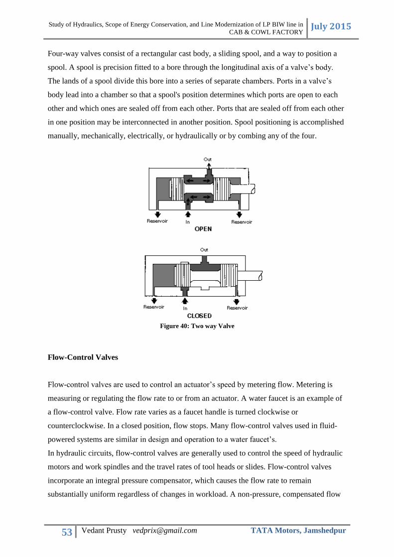
Study of Hydraulics, Scope of Energy Conservation, and Line Modernization of LP BIW line in
CAB & COWL FACTORY July 2015
53 Vedant Prusty [email protected] TATA Motors, Jamshedpur
Four-way valves consist of a rectangular cast body, a sliding spool, and a way to position a
spool. A spool is precision fitted to a bore through the longitudinal axis of a valve’s body.
The lands of a spool divide this bore into a series of separate chambers. Ports in a valve’s
body lead into a chamber so that a spool's position determines which ports are open to each
other and which ones are sealed off from each other. Ports that are sealed off from each other
in one position may be interconnected in another position. Spool positioning is accomplished
manually, mechanically, electrically, or hydraulically or by combing any of the four.
Figure 40: Two way Valve
Flow-Control Valves
Flow-control valves are used to control an actuator’s speed by metering flow. Metering is
measuring or regulating the flow rate to or from an actuator. A water faucet is an example of
a flow-control valve. Flow rate varies as a faucet handle is turned clockwise or
counterclockwise. In a closed position, flow stops. Many flow-control valves used in fluid-
powered systems are similar in design and operation to a water faucet’s.
In hydraulic circuits, flow-control valves are generally used to control the speed of hydraulic
motors and work spindles and the travel rates of tool heads or slides. Flow-control valves
incorporate an integral pressure compensator, which causes the flow rate to remain
substantially uniform regardless of changes in workload. A non-pressure, compensated flow

Study of Hydraulics, Scope of Energy Conservation, and Line Modernization of LP BIW line in
CAB & COWL FACTORY July 2015
54 Vedant Prusty [email protected] TATA Motors, Jamshedpur
control, such as a needle valve or fixed restriction, allows changes in the flow rate when
pressure drop through it changes.
Variations of the basic flow-control valves are the flow-control-and-check valves and the
flow-control-and-overload relief valves. Models in the flow-control-and-check-valve series
incorporate an integral check valve to allow reverse free flow. Models in the flow-control
and- overload-relief-valve series incorporate an integral relief valve to limit system pressure.
Some of these valves are gasket-mounted, and some are panel-mounted.

Study of Hydraulics, Scope of Energy Conservation, and Line Modernization of LP BIW line in
CAB & COWL FACTORY July 2015
55 Vedant Prusty [email protected] TATA Motors, Jamshedpur
HYDRAULIC FLUIDS
Hydraulic fluid is a medium to transfer power in the system or the machinery. Hydraulic
fluids play a very important role in the developing world. The fluids are classified on the
basis of their viscosity, which makes a chart which is useful for the industries to select the
fluid for the particular function. The classifications range from a simple ISO (International
Organization for Standardization) to the recent classification ASTM D 6080-97 (classifying
based on viscosity).
Types of hydraulic fluids
According to ISO there are three different types of fluids according to their source of
availability and purpose of use.
Figure 41: Classification of Hydraulic Fluids

Study of Hydraulics, Scope of Energy Conservation, and Line Modernization of LP BIW line in
CAB & COWL FACTORY July 2015
56 Vedant Prusty [email protected] TATA Motors, Jamshedpur
Mineral-Oil based Hydraulic fluids
As these have a mineral oil base, so they are named as Mineral-oil-Based Hydraulic fluids.
This kind of fluids will have high performance at lower cost. These mineral oils are further
classified as HH, HL and HM fluids.
Type HH fluids are refined mineral oil fluids which do not have any additives. These fluids
are able to transfer power but have less properties of lubrication and unable to withstand high
temperature. These types of fluid have a limited usage in industries. Some of the uses are
manually used jacks and pumps, low pressure hydraulic system etc.
Type HL fluids are refined mineral oils which contain oxidants and rust inhibitors which help
the system to be protected from chemical attack and water contamination. These fluids are
mainly used in piston pump applications.
HM is a version of HL-type fluids which have improved anti-wear additives. These fluids use
phosphorus, zinc and sulphur components to get their anti-wear properties. These are the
fluids mainly used in the high pressure hydraulic system.
Fire Resistant Fluids
These fluids generate less heat when burnt than those of mineral oil based fluids. As the name
suggests these fluids are mainly used in industries where there are chances of fire hazards,
such as foundries, military, die-casting and basic metal industry. These fluids are made of
lower BTU (British Thermal Unit) compared to those of mineral oil based fluids, such as
water-glycol, phosphate ester and polyol esters. ISO have classified these fluids as
HFAE(soluble oils), HFAS(high water-based fluids), HFB(invert emulsions), HFC(water
glycols), HFDR(phosphate ester) and HRDU(polyol esters).
Environmental Acceptable Hydraulic Fluids (EAHF)
These fluids are basically used in the application where there is a risk of leakage or spills into
the environment, which may cause some damage to the environment. These fluids are not
harmful to the aquatic creatures and they are biodegradable. These fluids are used in forestry,
lawn equipment, off-shore drilling, dams and maritime industries. The ISO have classified

Study of Hydraulics, Scope of Energy Conservation, and Line Modernization of LP BIW line in
CAB & COWL FACTORY July 2015
57 Vedant Prusty [email protected] TATA Motors, Jamshedpur
these fluids as HETG (based on natural vegetable oils), HEES (based on synthetic esters),
HEPG (polyglycol fluids) and HEPR (polyalphaolefin types).
Table 2: Physical Parameters of Hydraulic Fluids

Study of Hydraulics, Scope of Energy Conservation, and Line Modernization of LP BIW line in
CAB & COWL FACTORY July 2015
58 Vedant Prusty [email protected] TATA Motors, Jamshedpur
The desirable properties of Hydraulic Fluids are as follows:
Power Transmission: - fluid must flow , must be as incompressible as possible.
Lubrication:- For long component life the oil must contain the necessary additives to
ensure high anti wear characteristics.
Sealing: - the fluid is the only seal against pressure inside a hydraulic component. The
close mechanical fit and oil viscosity determines leakage rate.
Cooling:- Circulation of the oil through lines and round the walls of the reservoir
gives up heat that is generated in the system.
Prevent rust
Prevent formation of sludge, gum and varnish
Depress foaming
Maintain its own stability and thereby reduce fluid replacement
cost
Maintain relatively stable body over a wide temperature range
Prevent corrosion and pitting
Separate out water
Compatibility with seals and gaskets
Random oils cannot be used as hydraulic oils. They have specific requirements of viscosity,
flammability, etc. The temperature coefficient of expansion must also be considered. For e.g.
above 100 degrees C, for every rise of 1 degree, volume of oil may expand by upto 1
percent. Such figures and facts must be taken into consideration before selecting hydraulic
fluids and relevant cooling mechanisms should be introduced.
Fluids Used in LP Line
The fluids used in Cab & Cowl Factory for hydraulics include HLP-46 (EDAG Line,
accumulators), and VG-68 (all valves, and LP fabrication).

Study of Hydraulics, Scope of Energy Conservation, and Line Modernization of LP BIW line in
CAB & COWL FACTORY July 2015
59 Vedant Prusty [email protected] TATA Motors, Jamshedpur
Table 3: HLP-46 technical specifications

Study of Hydraulics, Scope of Energy Conservation, and Line Modernization of LP BIW line in
CAB & COWL FACTORY July 2015
60 Vedant Prusty [email protected] TATA Motors, Jamshedpur
SCOPE IMPROVING LINE EFFICINCY AND ENERGY
CONSERVATION
The Power Pack is in severe need of repair and maintenance. Presently, the pressure
gauge is non-functional and the pressure relief valve is jammed. The pressure cannot
be adjusted in the event of major changes to line.
The Power Pack has leakage points on the chassis.
A full replacement of the Power Pack is highly recommended, keeping in mind that
station 1 to 5 of LP line are non-functional.
Stations 1 to 5 to be decommissioned since they are not in use. However, the power
supply remains on to their weld guns, and hydraulic supply to the valves.
The Line may be re-planned to optimize production. Present line is over 25 years old.
Floor Plan and Hydraulic/Pneumatic Circuit drawings need to be made/acquired for
maintenance and documentation purposes.
DCV with Tandem Neutral or Center should be used wherever possible. This will
ensure that during lockout condition, the pressure lines is directly connected to tank,
leaving the pump supplying pressure and no-load condition, thereby reducing energy
conservation.
(Pump flow is allowed to flow back to the tank through the
DCV when it is in neutral. This will keep the pressure low
when the valve is in neutral. In this situation, the system is
said to be unloaded because the power consumption is
reduced. This wastes much less energy than does a closed
centre neutral, which forces fluid over the pressure relief
valve at high pressure. The cylinder will be held in position
since the outlet ports are blocked.)
Cylinders with internal cushioning may be applied wherever possible.
All old Pressure, check and DC Valves may be replaced by modern stack type valves
for better efficiency valve operation and in space utilization

Study of Hydraulics, Scope of Energy Conservation, and Line Modernization of LP BIW line in
CAB & COWL FACTORY July 2015
61 Vedant Prusty [email protected] TATA Motors, Jamshedpur
Each station’s pressure line is to be isolated using valves. This allows maintenance or
shut down of individual station without affecting whole line.
Air Conditioning of whole facility if possible to keep hydraulic oil temperature within
20 degree Celsius.
SCOPE FOR PLC AND SCADA
Presently, the LP line uses simple electrical relays for the logic operation of the line. Each
station has an independent control panel. When two operators at each station start and finish
their respective work cycles, they press the required buttons on the operator panel. When all
such workers at all stations have finished their respective work cycle, the line moves ahead,
with the help of the chain and sprocket arrangement.
Figure 42: Electrical Relays Panel for LP Line
The hydraulic and pneumatic functions are then manually controlled at each station, i.e. the
raising or lowering of the scissor lift and the inversion mechanism (hydraulic) and the
opening and closing of the fixtures (pneumatic) are all manually controlled.

Study of Hydraulics, Scope of Energy Conservation, and Line Modernization of LP BIW line in
CAB & COWL FACTORY July 2015
62 Vedant Prusty [email protected] TATA Motors, Jamshedpur
Considering the fact that LP line produces upto 200 cowls per day, and that its products are
still associated with highest demand and with maximum revenue generation, the line over 25
year old line is in desperate need of modernization. Simple robust automation may go a long
way in improving the manufacturing process, reducing lead time, improving line efficiency
and reducing cost of production.
Figure 43: Operator Panel
Programmable Logic Controller or PLC is a computing system used to control
electromechanical processes.
SCADA stands for Supervisory Control and Data Acquisition. It is a type of industrial control
system that is used to monitor and control facilities and infrastructure in industries.
The implementation of PLC and SCADA would greatly help in optimizing the lines
performance.
PLC and SCADA systems can play a vital role in the modernization of the LP lines industrial
and automation environment. From the individual PLC controlling a discrete station to a line
wide integrated PLC and SCADA system, this may provide a total system solution.
The flexibility of PLC/SCADA approach allows combination of what is needed for a truly
customized solution. Modicon Programmable Automation Controllers (PACs) from
Schneider Electric for example, are built to suit the requirements of the process industry. In
such custom made devices, the hardware is modular and scalable, and supports a full range of
input/output modules, along with dedicated communications and fieldbus modules for
connection to smart devices and instrumentation.

Study of Hydraulics, Scope of Energy Conservation, and Line Modernization of LP BIW line in
CAB & COWL FACTORY July 2015
63 Vedant Prusty [email protected] TATA Motors, Jamshedpur
The SCADA system helps increase productivity with its reliable, high performance operator
interface that can be customized to meet the LP lines specific process and business
requirements.
The development, operation and maintainability of applications which significantly reduce
risk and development time is necessary in the LP line today.
Integration of SCADA and PLC into the present system is a plausible solution within
financial limits. The logic control of each stations work cycle, the overall line movement, the
control of fluid pressure, and hydraulic power pack can all be automated through such a
system, and replace the present hefty Electrical panel.
Over and above this, error detection and troubleshooting/maintenance operations stand highly
simplified.
The various points that need to be considered for planning and implementing such a project
would include:
Project development
Design standards (automation, control concepts, protection, instrumentation,
redundancy, architecture, IT security, graphics, alarms, etc)
Performance standards & requirements
Control room requirements
PLC/SCADA integration
Specification preparation and analysis
Project Management
Hardware supply and installation
Network and communication systems design
Plant information technology design and setup
Functional design, configuration, testing, commissioning and tuning
Electrical systems engineering including power and cabling systems design
Instrumentation and field equipment
Documentation and training
Automation level improvements

Study of Hydraulics, Scope of Energy Conservation, and Line Modernization of LP BIW line in
CAB & COWL FACTORY July 2015
64 Vedant Prusty [email protected] TATA Motors, Jamshedpur
REFERENCES & BIBLIOGRAPHY
“HYDRAULIC FLUIDS: The pressure to perform better” by Betty Catalina Rostro
and Nancy Nalence (Tribology and Lubrication Technology, April 2007)
Fluid Mechanics and Hydraulic Machines by R.K. Bansal
Hydraulics Manual, US Army, 1997
Improving Performance of an Energy Efficient Hydraulic Circuit by Tonglin Shang,
April 2004
Energy Energy Saving Strategies of an Efficient Electro Efficient Electro -Hydraulic
Circuit (A review ), by Ayman A. Aly, July 2014.
Related Documents