STUDY OF FRICTION WELDING A THESIS SUBMITTED IN PARTIAL FULFILLMENT OF THE REQUIREMENTS FOR THE DEGREE OF Bachelor of Technology In Mechanical Engineering By RANJAN SAHOO & PINAKI SAMANTARAY Department of Mechanical Engineering National Institute of Technology Rourkela 2007

Welcome message from author
This document is posted to help you gain knowledge. Please leave a comment to let me know what you think about it! Share it to your friends and learn new things together.
Transcript

STUDY OF FRICTION WELDING
A THESIS SUBMITTED IN PARTIAL FULFILLMENT
OF THE REQUIREMENTS FOR THE DEGREE OF
Bachelor of Technology In
Mechanical Engineering
By
RANJAN SAHOO &
PINAKI SAMANTARAY
Department of Mechanical Engineering
National Institute of Technology Rourkela
2007

STUDY OF FRICTION WELDING
A THESIS SUBMITTED IN PARTIAL FULFILLMENT
OF THE REQUIREMENTS FOR THE DEGREE OF
Bachelor of Technology In
Mechanical Engineering By
RANJAN SAHOO &
PINAKI SAMANTARAY Under the Guidance of
Prof. B.K. NANDA
Department of Mechanical Engineering
National Institute of Technology Rourkela
2007
National Institute of Technology Rourkela
CERTIFICATE
This is to certify that the thesis entitled, “STUDY OF FRICTION WELDING” submitted by
Sri Ranjan Sahoo & Sri Pinaki Samantaray in partial fulfillment of the requirements for the
award of Bachelor of Technology Degree in Mechanical Engineering at the National Institute
of Technology, Rourkela (Deemed University) is an authentic work carried out by him under
my supervision and guidance.
To the best of my knowledge, the matter embodied in the thesis has not been submitted to any
other University / Institute for the award of any Degree or Diploma.
Date: Prof. B.K.Nanda
Dept. of Mechanical Engineering
National Institute of Technology
Rourkela - 769008
National Institute of Technology Rourkela
ACKNOWLEDGEMENT
I would like to articulate my deep gratitude to my project guide Prof. B.K. Nanda who has
always been my motivation for carrying out the project.
It is my pleasure to refer Microsoft word 2003 of which the compilation of this report would
have been impossible.
An assemblage of this nature could never have been attempted without reference to and
inspiration from the works of others whose details are mentioned in reference section. I
acknowledge my indebtedness to all of them.
Last but not the least to all of my friends who were patiently extended all sorts of help for
accomplishing this undertaking.
Ranjan Sahoo
Date:
Pinaki Samantaray
Dept. of Mechanical Engineering
National Institute of Technology
Rourkela - 76900
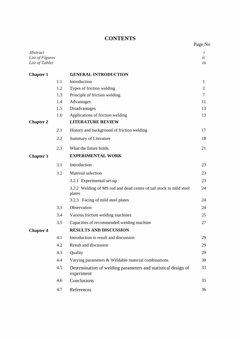
CONTENTS Page No
Abstract i List of Figures ii List of Tables iii Chapter 1 GENERAL INTRODUCTION 1.1 Introduction 1 1.2 Types of friction welding 2 1.3 Principle of friction welding 7 1.4 Advantages 11 1.5 Disadvantages 13 1.6 Applications of friction welding 13 Chapter 2 LITERATURE REVIEW
2.1 History and background of friction welding 17
2.2 Summary of Literature 18
2.3 What the future holds. 21
Chapter 3 EXPERIMENTAL WORK
3.1 Introduction 23
3.2 Material selection 23
3.2.1 Experimental set-up 23
3.2.2 Welding of MS rod and dead centre of tail stock to mild steel plates
24
3.2.3 Facing of mild steel plates 24
3.3 Observation 24
3.4 Various friction welding machines 25
3.5 Capacities of recommended welding machine 27
Chapter 4 RESULTS AND DISCUSSION
4.1 Introduction to result and discussion 29
4.2 Result and discussion 29
4.3 Quality 29
4.4 Varying parameters & Weldable material combinations 30
4.5 Determination of welding parameters and statistical design of experiment
33
4.6 Conclusions 35
4.7 References 36

ABSTRACT
Friction welding(FW) is a fairly recent technique that utilizes a non-consumable
welding tool to generate frictional heat and plastic deformation at the welding location, there
by affecting the formation of a joint while the material is in solid state. The principal
advantage of frictional welding, being a solid state process, low distortion, absence of melt-
related defects and high joint strength, even in those alloys that are that are considered non-
weldable by conventional welding techniques. Furthermore, friction welded joints are
characterized by the absence of filler-induced problems or defects, since the technique
requires no filler, and by the low hydrogen contents in the joints,an important consideration
in welding steel and other alloys susceptible to hydrogen damage. FW can be used to produce
butt, corner, lap, T, spot, fillet and hem joints, as well as to weld hollow objects, such as
tanks and tubes or pipes, stock with different thickness, tapered section and parts with 3-
dimensional contours. The technique can produce joints utilizing equipment based on
traditional machine tool technologies, and it has been used to weld a variety of similar and
dissimilar alloys as well as for welding metal matrix composites and for repairing the existing
joints. Replacement of fastened joints with FW welded joints can lead to significant weight
and cost savings, attractive propositions for many industries. This document reviews some of
the FW work performed to date, presents a brief account of mechanical testing of welded
joints, tackles the issue of generating joint allowables, and offers some remarks and
observation. FW is a leap forward in manufacturing technology, a leap that will benefit a
wide range of industries, including transportation industry in general and the airframe
industry in particular.
i

LIST OF FIGURES Fig 1 Principle of friction welding 7
Page No.
Fig 2 Phases of friction welding 9
Fig 3 Applications of friction welding 14 Fig 4 Experimental set-up 23 Fig 5 10 ton machine welding axle housing for Toyota 25
Fig 6 Variation of welding with time 33
Fig 7 Parameters for continous drive friction welding 34
Fig 8 Effects of friction time on tensile strength 34
Fig 9 Effects of friction time on joint tensile strength 35
ii

LIST OF TABLES Table: 1 LFW Research programme 19
Table: 2 Capacities of recommended welding machines 27
Table: 3 Various combinations . 29
Table: 4 Varying parameters 30
Table: 5 Weldable material combinations 32
iii

Chapter 1
GENERAL INTRODUCTION

1.1 Introduction
A method of operating on a workpiece comprises offering a probe of
material harder than the workpiece material to a continuous surface of the workpiece causing
relative cyclic movement between the probe and the workpiece while urging the probe and
workpiece together whereby frictional heat is generated as the probe enters the workpiece so
as to create a plasticized region in the workpiece material around the probe, stopping the
relative cyclic movement, and allowing the plasticized material to solidify around the probe.
This technique, which we refer to as "friction welding" provides a very simple method of
joining a probe to a workpiece. The method can be used for repairing cracks and the like
within a workpiece or for joining members, such as studs or bushes, to a workpiece. Another
aspect of the invention comprises causing a probe of material harder than the workpiece
material to enter the joint region and opposed portions of the workpieces on either side of the
joint.
Friction welding is a type of forge welding, i.e. welding is done by the
application of pressure. Friction generates heat, if two surfaces are rubbed together, enough
heat can be generated and the temperature can be raised to the level where the parts subjected
to the friction may be fused together.
In conventional friction welding, relative rotation between a pair of workpieces is
caused while the work pieces are urged together. Typically thereafter once sufficient heat is
built at the interface between the workpieces, relative rotation is stopped and the workpieces
are urged together under forging force which may be same as or greater than the original
urging force.
“Friction Welding” (FW) is a group of solid-state [welding] processes using heat
generated through mechanical friction between a moving workpiece, with the addition of an
upsetting force to plastically displace material. Many dissimilar metal combinations can be
joined and there are a number of process variations including:
1
1.2 TYPES OF FRICTION WELDING:
Linear Friction Welding:
Linear Friction Welding (LFW) is seen a key technology for the aerospace
industry as it enables the joining of difficult to bond materials, can be used as a repair
process, and to build the complex structures required for today's gas turbines. Essentially, it is
a non-melting fusion process producing high integrity welds with little prior surface
preparation required.
Linear friction welding, (so named because the relative motion is linear across the
interface, rather than rotary), is already used to join blades onto discs in the aeroengine
industry. Lower cost linear friction welding machines are now being developed for
automotive applications, such as the fabrication of brake discs, wheel rims and engine parts.
As the parts to be welded are forced into intimate contact, a fully reversed motion is imposed
on part of the system. This generates frictional heat in the immediate region about the weld
plane, thereby softening a finite volume of material. As the weld proceeds, a portion of this
visco-plastic layer is extruded at the periphery of the weld interface, in rippled sheets of metal
known as flash. This should ensure that any interfacial contaminant is expelled. The
combination of fast joining times of the order of a few seconds, and the direct heat input at
the weld interface, gives rise to relatively small heat affected zones. This, by judicious
selection of components geometry, this also limits process induced distortions.
To this date, precious little research has been done in the area of LFW.
It is generally accepted that friction welding can be separated into (i) a dry friction stage,
followed by (ii) an increased asperity contact, and (iii) some sort of steady state once the
relatively high weld temperature has been acquired. It is not clear how the surface
contaminants are removed - especially from the mid-point of the weld.
2

The challenge lies with the tribology of the problem, heat generation,
heat conduction, and more importantly, the representation of the visco-plastic material flow
during steady state LFW. It is essential that both these matters be addressed systematically, so
that an accurate formulation of an average material extrusion model can be constructed. This
will ensure that the computational cost incurred in running finite element representations of
the process be kept within acceptable bounds. The ultimate aim is to develop a complete
LFW FEA process modelling capability within the next 3 years.
Spin Welding:
Four different phases can be distinguished in the vibration welding
process; the solid friction phase, the transient phase, the steady-state phase and the cooling
phase.
In the solid friction phase, heat is generated as a result of the friction
between the two surfaces. This causes the polymer material to heat up until the melting point
is reached. The heat generated is dependent on the applied tangential velocity and the
pressure.
In the second phase, a thin molten polymer layer is formed which
grows as a result of the ongoing heat generation. In this stage heat is generated by viscous
dissipation. At first only a thin molten layer exists and consequently the shear rate and
viscous heating contributions are large. As the thickness of the molten layer increases the
degree of viscous heating decreases.
Thereafter, (start of third phase) the melting rate equals the outward
flow rate (steady state). As soon as this phase has been reached, the thickness of the molten
layer is constant. The steady-state is maintained until a certain "melt down depth" has been
reached at which point the rotation is stopped.
At this point (phase 4) the polymer melt cools and solidification starts,
while film drainage still occurs since the welding pressure remains. After all the material has
solidified, drainage stops and the joint is formed."
3
Rotary Friction Welding:

Rotary friction welding, in which one component is rotated against the other,
is the most commonly used of the processes, and many carbon steel vehicle axles and sub-
axles are assembled in this way. The process is also used to fabricate suspension rods,
steering columns, gear box forks and driveshafts, as well as engine valves, in which the
ability to join dissimilar materials means that the valve stem and head can be made of
materials suited to their different duty cycles in service.
Inertia Friction Welding:
Inertia Friction Welding is a variation of friction welding in which the
energy required to make the weld is supplied primarily by the stored rotational kinetic energy
of the welding machine.
In Inertia Welding, one of the work pieces is connected to a flywheel and the
other is restrained from rotating. The flywheel is accelerated to a predetermined rotational
speed, storing the required energy. The drive motor is disengaged and the work pieces are
forced together by the friction welding force. This causes the faying surfaces to rub together
under pressure. The kinetic energy stored in the rotating flywheel is dissipated as heat
through friction at the weld interface as the flywheel speed decreases. An increase in friction
welding force (forge force) may be applied before rotation stops. The forge force is
maintained for a predetermined time after rotation ceases.
Friction Surfacing
Friction Surfacing is a process derived from friction welding whereby a
coating material, in rod form (termed the Mechtrode TM) is rotated under pressure,
generating a plasticised layer in the rod at the interface with the substrate. By moving a
substrate across the face of the rotating rod a plasticised layer between 0.2-2.5mm thick is
deposited (depending on mechtrode diameter and coating material). The resulting composite
material is created to provide the characteristics demanded by any given application.
4
During the coating process, the applied layer of metal reaches a temperature
near the melting point whilst simultaneously undergoing plastic deformation. The coating is

thus the product of a hot forging action, as opposed to the casting mechanism inherent in
welding and spraying processes. This important difference means that many of the defects
commonly associated with these techniques are avoided.
Friction Stud Welding
In early 1998, friction stud welding was performed commercially at a
depth of 1,300 feet (394m) and involved the friction welding of anode continuity tails to riser
base piles using a work-class ROV. The friction welding equipment used was a Circle
Technologies HMS 3000, which is hydraulically-driven, electronically-controlled, and rated
to a depth of 3,000 feet (910m).
Based on this concept, the Naval Sea Systems Command (NAVSEA)
initiated another program to evaluate underwater friction stud welding for use in submarine
rescue. The program required interfacing the HMS 3000 friction stud welder with the Navy's
atmospheric diving suit (ADS), rated to 2,000 feet (606m). The feasibility of this concept was
demonstrated in 2001 by Oceaneering International using their WASP ADS and the HMS
3000 friction stud welding system.
Friction stud welding provides the capability to weld a pattern of studs to
the hull of a disable submarine, to which a pad- eye can be attached for the SRC haul-down
cable and life support gas can be provided by means of a hot tap process using hollow studs.
Combined with an ADS, the system provides rescue capabilities well beyond 300 feet (91m).
Concurrent with the Navy's application for underwater friction stud
welding for submarine rescue, Oceaneering pursued the application commercially for
offshore platform repairs. However, initial research showed that there was a limited amount
of accurate public information on the mechanical properties of underwater friction stud
welding. As such, the use of this process for any offshore repair without a full evaluation for
mechanical, corrosion, and fatigue would not be acceptable.
5
Friction Stir Welding
Friction stir welding also produces a plasticised region of material, but in a
different manner. A non-consumable rotating tool is pushed into the materials to be welded
and then the central pin, or probe, followed by the shoulder, is brought into contact with the
two parts to be joined, figure 2. The rotation of the tool heats up and plasticises the materials
it is in contact with and, as the tool moves along the joint line, material from the front of the
tool is swept around this plasticised annulus to the rear, so eliminating the interface
Friction stir welding (FSW) is a novel welding technique invented by The Welding Institute
(TWI) in 1991. FSW is actually a solid-state joining process that is a combination of
extruding and forging and is not a true welding process. Since the process occurs at a
temperature below the melting point of the work piece material, FSW has several advantages
over fusion welding. Some of the process advantages are given in the following list:
1.FSW is energy efficient.
2.FSW requires minimal, if any, consumables.
3.FSW produces desirable microstructures in the weld and heat-affected zones
4.FSW is environmentally "friendly" (no fumes, noise, or sparks)
5.FSW can successfully join materials that are "unweldable" by fusion welding methods.
6.FSW produces less distortion than fusion welding techniques.
1.3 PRINCIPLE:
Traditionally, friction welding is carried out by moving one component
relative to the other along a common interface, while applying a compressive force across the
joint. The friction heating generated at the interface softens both components, and when they
become plasticised the interface material is extruded out of the edges of the joint so that clean
material from each component is left along the original interface. The relative motion is then
stopped, and a higher final compressive force may be applied before the joint is allowed to
cool. The key to friction welding is that no molten material is generated, the weld being
formed in the solid state.
The principle of this process is the changing of mechanical energy into
heat energy. One component is gripped and rotated about its axis while the other component
to be welded to it is gripped and does not rotate but can be moved axially to make contact
with the rotating component. At a point fusion temperature is reached, then rotation is
6
stopped and forging pressure is applied. Then heat is generated due to friction and is
concentrated and localized at the interface, grain structure is refined by hot work.Then
welding is done, but there will not occur the melting of parent metal.

Briefly the friction-welding process consists in bringing into contact two
elements to be welded while one of the two is static and the other is rotated rapidly on its
axis.As the soon as the heat generated by attrition at the interface is sufficient for solid state
welding without melting,the rotation is stopped and the elements are forced together under
pressure producing local forging which concludes the intimate joining and also expels at the
joint all surface contamination and some of the upset material called flash.
In friction welding one component is rotated and one component is held
stationary. The part that is rotated is brought into contact with the stationary component and
when enough heat has been generated to bring the components to a plastic state and the
desired burnoff has been achieved, rotation is stopped. More axial force is then applied
between the two components resulting in a solid state bond at the interface forming a friction
welded joint.
One component rotated rapidly, the other is stationary
Rotating and stationary components brought together into contact and force applied
Axial force is increased to bring components into a plastic state at interface
7
Rotation is stopped and more axial force is applied

Result - A full cross sectional weld in the parent material
Fig 1
Many dissimilar metal combination can be joined and there are a number of
process variation including:
Spin welding:four different phases can be distinguished in the vibration
welding process,the solid friction phase,the transient phase,the steady state phase, the cooling
phase.
1. In the solid friction phase heat is generated as a result of friction between two
surfaces.This causes the polymer material to heat up until the melting point is reached.The
heat generated is dependent on applied tangential velocity and pressure.
2. In the second phase a thin molten polymer is formed which grows as result of ongoing
heat generation. In this stage heat is generated by viscous dissipation. At first only a thin
molten layer exist and consequently the shear rate and viscosity heating contribution are
large. As the thickness of molten layer increases the degree of viscous heating decreases.
3. Thereafter(start of third phase) the melting rate equals the outward flow rate(steady
state).As soon as the phase has been reached, the thickness of molten layer is constant.The
steady state is maintained until a certain melt down depth has been reached, at which point
the rotation is stopped.
4. At this point (phase 4)the polymer melt cools and solidification starts,while film drainage
still occurs since the welding pressure remains. After all the materials has solidified, drainage
stops and join is formed.
8
.

In the direct drive variation of friction welding, one of the workpieces is
attached to a motor driven unit, while the other is restrained from rotation. The motor driven
workpiece is rotated at a predetermined constant speed. The workpieces to be welded are
moved together, and then a friction welding force is applied. Heat is generated as the faying
surfaces (weld interface) rub together. This continues for a predetermined time, or until a
preset amount of upset takes place. The rotational driving force is discontinued, and the
rotating workpiece is stopped by the application of a braking force. The friction welding
force is maintained or increased for a predetermined time after rotation ceases (forge force).
Phase 1
Low temp interface heat cycle by spinning one component against another stationary component.
Fig -2 9
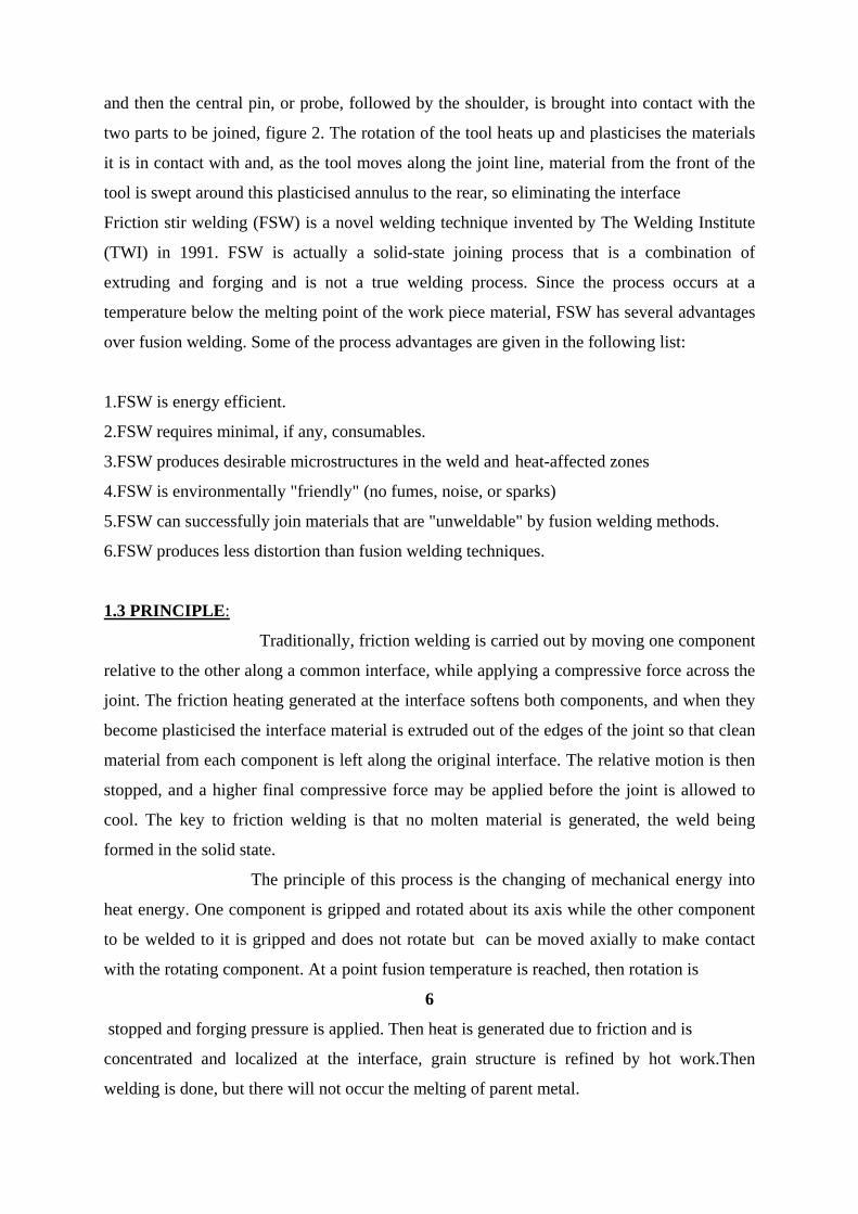
Phase 2
Solid forging cycle showing displaced plastic state material when final axial forging force is
applied.
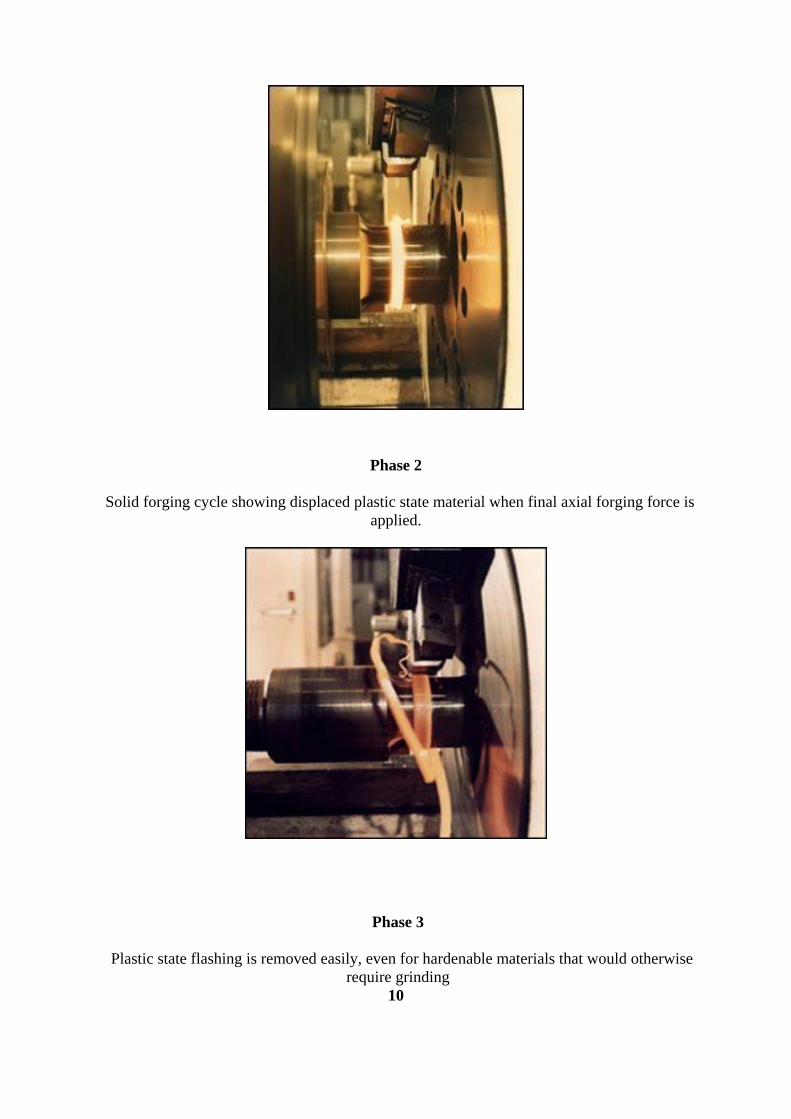
Phase 3
Plastic state flashing is removed easily, even for hardenable materials that would otherwise require grinding
10
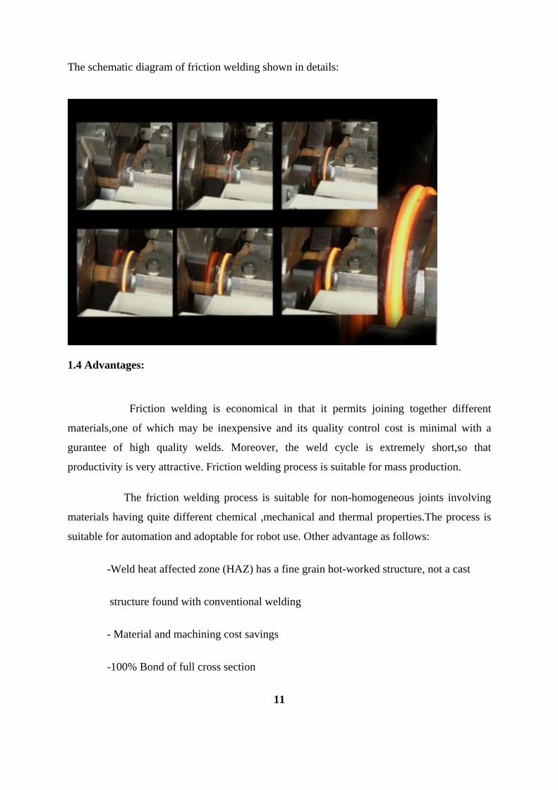
The schematic diagram of friction welding shown in details:
1.4 Advantages:
Friction welding is economical in that it permits joining together different
materials,one of which may be inexpensive and its quality control cost is minimal with a
gurantee of high quality welds. Moreover, the weld cycle is extremely short,so that
productivity is very attractive. Friction welding process is suitable for mass production.
The friction welding process is suitable for non-homogeneous joints involving
materials having quite different chemical ,mechanical and thermal properties.The process is
suitable for automation and adoptable for robot use. Other advantage as follows:
-Weld heat affected zone (HAZ) has a fine grain hot-worked structure, not a cast
structure found with conventional welding
- Material and machining cost savings
-100% Bond of full cross section
11

- High production rates
-Automatic repeatability
-Stronger than parent material, with excellent fatigue resistance
-Similar and dissimilar material joined with no added fluxes or filler metals
-low distortion,even in long welds
-excellent mechanical properties as proven by fatigue, tensile,bend tests
-no fume is produced
-no porosity
-no spatter
- no filler wire is required for welding
-no welder certification is required
-can operate in all positions
-more energy efficient than other welding technologies
-environmentally friendly process minimizes energy consumption and generate no
smoke, gasses or waste stream
-joint strength equal or greater than that of parent material
-join highly dissimilar metal combination to optimize your product’s quality and
properties
-save labor, material and operations through near net size design
-join less costly, lighter or tubular material to expensive material.
12

1.5 Disadvantages:
The disadvantage of friction welding are that not every configuration is feasible,that a
machine of sufficient power is needed and that for short runs the process may not be
economical.
Apart from the cost of equipment ,which must be suitable for the intended joints,the
friction welding process has some costs in tooling and set up that must be taken into account
when calculating the costs per weld.Tight cocentricity requirements,when needed,may be
difficult to meet. Also finishing operations may be requested which sum up to the total cost.
1.6 Application of friction welding: It can be used for various applications: 1.Commercial : Many commercial parts are candidates for inertia welding due to the fact that the weld is
accomplished quickly and with minimum clean-up. The fact that the weld is at 100%
strength, it provides a stronger part than traditional welds. Suggested uses are, but not limited
to: Tool extensions, tool blanks, baseball bats, golf putters, air cylinders, munitions, fasteners,
oil pipe and waterpipe fittings, bicycle parts, medical equipment, marine equipment,
electrical equipment, photographic and sound equipment.
2.Aerospace:
Full strength inertia welded parts are used in a wide variety of aerospace applications.Items
such as turbine wheels and shafts, pressure vessels, landing gear struts, ballscrew assemblies,
actuator components, gear blanks and gear assemblies are just a few examples. Many
Interface Welding parts have been used in satellites, space shuttles Hubble Telescope.
13
3.Hydraulic:
Hydraulic cylinders and valves are prime candidates for inertia welding. The cylinders can be
completely machined and the caps can be weld on afterwards providing for cost reductions
and minimal inventory requirements. For irregular shapes, the cylinder can be welded to a
larger piece of material to reduce cost and machine time. This process also lends itself to the
pistons and shaft weldments as well as side ports.
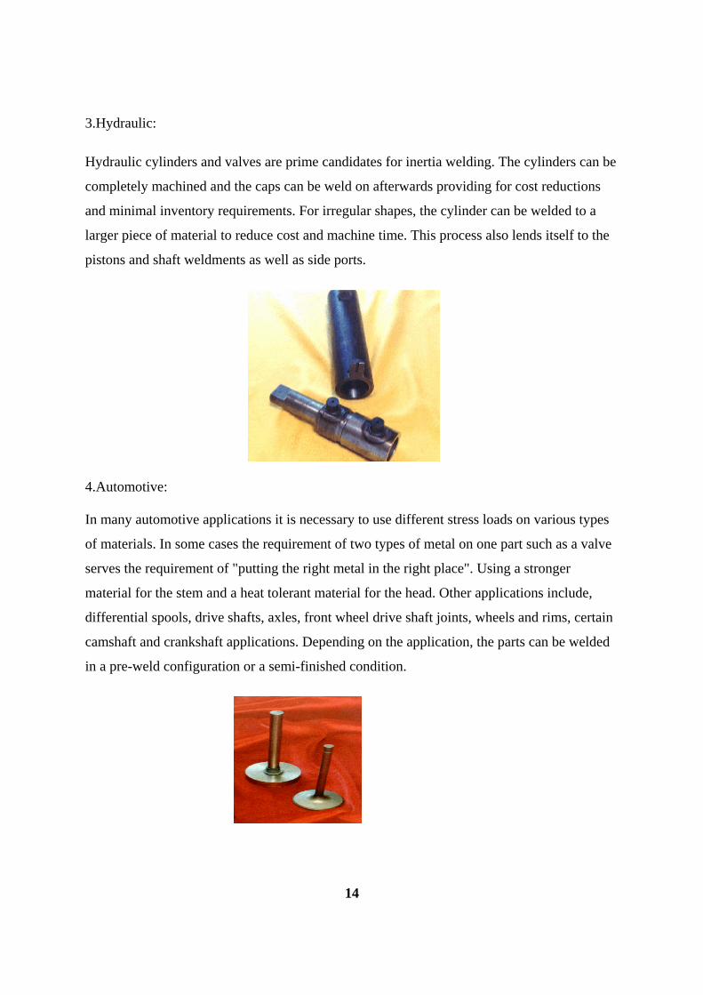
4.Automotive: In many automotive applications it is necessary to use different stress loads on various types
of materials. In some cases the requirement of two types of metal on one part such as a valve
serves the requirement of "putting the right metal in the right place". Using a stronger
material for the stem and a heat tolerant material for the head. Other applications include,
differential spools, drive shafts, axles, front wheel drive shaft joints, wheels and rims, certain
camshaft and crankshaft applications. Depending on the application, the parts can be welded
in a pre-weld configuration or a semi-finished condition.
14

5.Bi-metal:
Since 1966, Friction Welding, a solid state metal joining process, has been successfully used
to join a wide range of metals that are commonly considered not weldable. These full strength
welds, when helium leak tested, will exceed requirements of 10 -9, showing less leakage at
the joint than thru parent metal. Many discriminating companies use bi-metal weldments
produced by Interface Welding, which was founded in 1967.
Product applications range from electrical connectors, vacuum and pressure systems, satellite
heat pipes and pressure storage systems, turbine engine components, cryogenic fittings, glass
to metal seals and numerous other critical products. This technology is being expanded daily
in our facility.
Friction welders are versatile enough to join a wide range of part shapes, materials, and weld
sizes. Applications typically friction welded include aircraft and aerospace components,
cutting tools, agricultural machinery, automotive parts, oil field pieces, waste canisters,
military equipment, spindle blanks and bimetallic materials.
15

6.Agricultural field:
Friction welding is used extensively in the agricultural and trucking industries because the
welds are of forged quality, with a 100% butt joint weld throughout the contact area. This
bond is strong enough to handle the high stress and torque required of heavy machinery
components
7.Drill rods:
Manufactured in house, Colcrete Eurodrill can to provide DTH Friction Welded Drill Tube
and Rotary Drilling Friction Welded Drill Rods with A.P.I. connections.
Drill Pipe up to 139.7 mm (5 ½") diameter friction welded in house.
Drill Pipe is manufactured up to 406 mm (16") diameter and 9 metre effective length.
All tool joints are nitrided for extra wear resistance.
Fig-3
16

Chapter 2
LITERATURE REVIEW

3.1 History and background of friction welding
Over the years there has been many attempts to describe the phenomena of friction. It has
been a problem for mankind throughout the ages. As man became more inventive, surfaces
and materials were called upon to perform more complex tasks. As machines were required
to move faster and last longer, the intricate problem of friction became more involved. This
was due to animal fats, all types of greases from mammals to fish, and eventually mineral
oils. Refined forms of oils and greases have been the principle method of placing a boundary
layer between metals in order to increase life and reduce wear.
Science and technology could not have advanced to where it is today without understanding
the mechanism of friction and wear. Today we are encountering even newer requirements for
longer life and faster speeds both in the air and on the ground. This has brought about a new
generation of metals and materials that have increased wear life primarily through the
reduction of friction between mating components. Some have taken the form of harder metal
alloys and others are surface enhancements that perform better than oils or greases.
Magnaplate has been in the forefront of almost all these newer materials. These materials are
composites and or alloys that are diffused into or onto base metal substrates. In some cases,
new oxides or harder porous metals are developed electrochemically or by plasma spraying
or in some cases, multi layers of soft and hard metals are deposited and then diffused both
into and on top of the base metal.
The ever-growing pace of technological advancement remains a bulwark to the nation’s
economy, which relies on innovative processes that drive growth, particularly ones that are
applicable to a range of industries. One such innovative process that continues to make its
mark felt across a variety of sectors is friction welding. Friction welding is a proven and cost-
effective method of joining similar or highly dissimilar materials that has proven to be very
popular in Europe and Asia, but is largely unknown and vastly underutilized in the United
States. This is the case despite the fact that it is a preferred method in the aircraft and
automotive industries, and ironically, the first patent for this process was introduced in the
United States.
17

3.2 Summary of literature
It is common experience that the necessary force to commence sliding a material is greater
than that to maintain motion, and therefore the coefficient of static friction is greater than that
of dynamic friction. It has also been observed that the range of values of frictional forces
differ by orders of magnitude depending on the length scales of the applications, macroscopic
or nanoscopic.
As the French physicist Guillaume Amonton stated in his empirical law of sliding
friction, the friction force is proportional to the normal load, or if expressed mathematically
Friction force = coefficient of friction X normal load
In most cases the precise value of the coefficient of friction depends strongly on the
experimental conditions under which it is measured. In addition, a second law of friction
states that friction force is independent of the apparent area of contact between the two
surfaces. Charles Augustin de Coulomb, also, stated in his third law of macroscopic friction,
that friction force is independent of sliding velocity. The coefficient of dynamic friction is
expected to be nearly independent of ordinary sliding velocities, and similar behaviour is
exhibited for temperature changes, unless phase transformations appear at the interface. Initial attempts, by Amontons and Coulomb among others, assumed that mechanical
interlocking between rigid or elastically deforming asperities are responsible for the frictional
force and the consequent mechanical wear and heat generation. This model assumes two
bodies which perform both longitudinal and transverse motion at the same time; work is
performed by normal load after the upper body has returned to its lowest position, and all of
the potential energy is recovered. Unfortunately, macroscopic observations may not be in
agreement with this theory as highly polished and smooth surfaces are necessary for cold
welding and do not necessarily show low friction. An additional problem for this theory, is
that adsorbed films change friction by orders of magnitude while maintaining the same
roughness of the surface.
A.R.D. Industries produces friction welded components and does sub-contract friction
welding of customer's goods, for a broad variety of manufacturers, including agricultural,
automotive, electrical, forestry, mining, transportation and other related industries. A.R.D.
Industries is Canada's only friction welding sub-contract manufacturer.
18
Inertia Friction Welding (IFW), a division of SSD® Control Technology, Inc.
(SSD®) was founded in 1994 as Inertia Friction Welding, Inc., for the purpose of
manufacturing friction welding and other types of special machines. In January of
2002, SSD® and Inertia Friction Welding, Inc. merged and IFW became a division of SSD®.
According to the American Welding Society, the origins of friction welding date back
to 1891, when the first patent on the process was issued in the USA. More work progressed
throughout Europe as more patents were issued from 1920 to 1944, and in the USSR in 1956.
In the 1960's, friction welding was further developed in the USA by AMF, Caterpillar, and
Rockwell International. Rockwell built its own machines to weld spindles to truck differential
housings, AMF produced machines to weld steering worm shafts, and Caterpillar’s machines
welded turbochargers and hydraulic cylinders.
A British patent issued in 1969 described a linear reciprocating mechanism for
welding mild steel, although no further information was published. In the early 1980s, TWI
demonstrated the viability of the LFW technique for metals using modified equipment. The
design and build of a prototype electro-mechanical machine with a linear reciprocating
mechanism followed in the mid 1980s. Two similar machines are now located at an aircraft
engine manufacturer in Europe. Several other machines of alternative designs are operating in
the USA and Europe.
Although available for 10 years, the LFW process has only found industrial
application in aircraft engine manufacture, in part due to the high cost of the welding
machines. It has proved to be an ideal process for joining turbine blades to discs where the
high value-added cost of the components justifies the cost of a LFW machine. This approach
is more cost-effective than machining blade/disc assemblies from solid billets.
In recent years, LFW research programmes have addressed the following topics:
• Components with irregular cross-section and/or
complex shapes.
• Difficult to weld, heat
resisting alloys.
• Dissimilar material combinations and cast to
forged components.
• Gas shielding of reactive
materials.
• Joining single crystal nickel alloys to
polycrystalline alloys.
Table-1
19

However, to increase greatly the application of LFW in industries such as automotive
and power generation, the cost of linear friction welding machines must be drastically
reduced. An EU funded study has recently been completed to build a low cost LFW machine.
This increases TWI's capability to two machines. The newer machine (Linfric) is designed to
enable welds to be made on large structures.
Ellis(1977)examined the relationships between “friction time-workpiece diameter”,
“shortening-upsetting pressure” and “carbon equivalent-hardness variation”. Ishibashi et al.
(1983)selected stainless steel and high-speed steel as representative materials with an
appreciably difficult weldability, and obtained their suitable welding conditions. In their
work, distributions of alloying elements at and near the weld interfaces for joints of sufficient
strength were analyzed using an X-ray micro-analyzer. Murti and Sundaresan (1983)
directed a study about parameter optimization in friction welding of dissimilar materials.
Dunkerton (1986) investigated the effects of rotation speed, friction pressure and upsetting
pressure in all friction welding methods for steel. Yılbas et al. (1995) investigated the
mechanical and metallurgical properties of friction welded steel-aluminum and aluminum-
copper bars. Yılmaz (1993) investigated hardness variations and microstructures in the
welding zone of welded dissimilar materials.
As mentioned earlier, diametrical differences of the components generally create
difficulties in determination of the proper welding parameters because of the differences in
heating capacities of the components. Nentwig (1996) investigated the effect of cross-
sectional differences in the components in on the joint quality of friction welds. It was
concluded that: in comparing the friction welding of parts having different cross-sections
with those of equal cross-sections using same welding parameters, the heat input is
inadequate, and friction welding parameters for equal cross-sectioned parts cannot be
transferred automatically to cross-sections of different sizes.
Sahin and Akata (2001) investigated welding quality using tensile test results of
welded parts having different cross-sections. Akata et al. (2001) conducted a detailed study
about construction and controlling of friction welding set-up
20
2.3 What the Future Holds:
Given the challenges facing the manufacturing sector, friction welding, on the strength of its
unique advantages, is a process that makes increasing sense. Providing advantages that
manufacturing companies can readily leverage, friction welding machinery has seen an
astounding rise in inquiries from China and southern Asia over the last year.As engineers and
product designers delve deeper into this process, they will come away convinced that friction
welding can serve to optimize and perfect both the design of heretofore unrealized
components, and their cost of production. If, indeed, necessity is the mother of invention,
then friction welding has a substantive role to play in the future of global manufacturing.
Such has been the interest in friction stir welding, which was patented no so long ago, that
considerable effort is being made in transferring the technological benefits from aluminium
and magnesium to higher temperature materials such as copper, titanium and steels. TWI has
two projects in conjunction with several industrial users to develop the friction stir welding of
titanium and steels.
Another project on the friction stir welding of aluminium alloys involving industrial firms has
also recently started. This is assessing innovative weld joint geometries for friction stir
welding aluminium extrusions and wrought alloys together in transport structures. This will
take the process beyond its current use of mainly simple butt and lap joint configurations and
make it a much more flexible fabrication process. Other firms who are interested in the
benefits of adopting this new technology can join these consortia.
Friction welding can also assume the role of “assembling” prefabricated components and
materials in a variety of creative configurations in a more economic method, as per a
particular client’s needs and specifications. Importantly, according to metallurgical testing,
the friction welding process is solid state, and no welding rods or filler materials are used.
Only base metal material exists up to and across the faying surfaces. This is significant
because no material has melted.
When looking at the broader scope of what the process offers, without question, friction
welding produces a full cross-sectional porosity-free bond, reduces material waste and
enhances productivity by limiting time-consuming labor associated with pre-machining,”
21

says Stuart Carlson, a metallurgist with over 30 years’ experience in the field. “These factors
are especially vital to manufacturers in today’s economic environment,” he says,
“considering the current dramatic rise in the prices of aluminum, copper, steel, stainless steel,
titanium and inconel.” The friction welding process is completely automated via PLC and PC
control, and includes monitoring, testing and recording of process parameters to guarantee
quality. The universally accepted standards of friction welding are defined according to ISO
1562.
22

Chapter 3
EXPERIMENTAL WORK
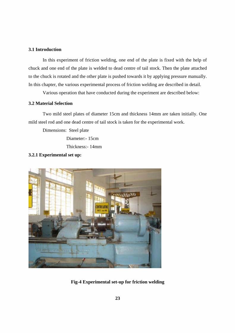
3.1 Introduction
In this experiment of friction welding, one end of the plate is fixed with the help of
chuck and one end of the plate is welded to dead centre of tail stock. Then the plate attached
to the chuck is rotated and the other plate is pushed towards it by applying pressure manually.
In this chapter, the various experimental process of friction welding are described in detail.
Various operation that have conducted during the experiment are described below:
3.2 Material Selection
Two mild steel plates of diameter 15cm and thickness 14mm are taken initially. One
mild steel rod and one dead centre of tail stock is taken for the experimental work.
Dimensions: Steel plate
Diameter:- 15cm
Thickness:- 14mm
3.2.1 Experimental set up:
Fig-4 Experimental set-up for friction welding
23

3.2.2 Welding of MS rod and dead centre of tail stock to the mild steel plates
One mild steel rod is welded to one mild steel plate and dead centre of tail
stock is welded to other plate.
Mild steel rod is taken, then center of the plate was located and it was held by
the help of tongue. Then, it is welded by using arc welding technique.Then, it is checked
wheather the welding is perpendicular or not. After welding, we have to check wheather it is
properly welded or not.The welding of MS rod to mild steel plate is done by arc
welding.One end of the other plate is welded to dead centre of tail stock.Welding is done so
that it can be attached to chuck only.
3.2.3 Facing of mild steel plates
As the plates were obtained by arc welding, the projected parts are very
tough to remove.So.it is removed by Hydro Copying Lathe.The projected parts are removed
by using cutting tool to get the desired dimensions which is required for the experimental
work.
Plates are obtained from a square shaped block by means of arc welding.After facing
operation, we have to do finishing operation to get the correct dimension. During finishing
operation, we have to check for diameter and thickness of mild steel plates by means of a
caliper. After finishing operation, we get the dimensions of the mild steel plates as:
Dimensions: diameter:- 14.6cm
thickness:- 14mm
3.3 Observation
After getting the mild steel plates as per the required dimension,we have to
perform the experiment on a Lathe machine.First,one part is attached to chuck of the lathe
and other part is fixed to tail stock.so,when the part attached to chuck is rotating and other
part moves towards it by means of using pressure manually.The chuck is to be rotated with a
specified rpm and the tailstock part is to brought into contact with the rotating part
slowly.Intially the rotating part is made into contact slowly and later on when the speed
gradually increases the two parts come into contact and heat is generated in the contact
region.After a sufficient amount of heat generation,the rotating part is stopped and the
tailstock is forced into the stopped rotating part.Then the two parts are allowed to cool for a
long period of time and the steel plates are joined.And finally the rod and deadcentre end are
taken out from the plates.
24
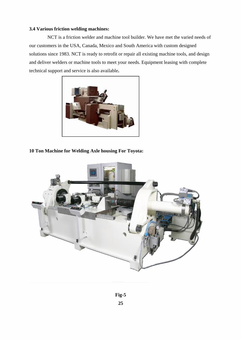
3.4 Various friction welding machines:
NCT is a friction welder and machine tool builder. We have met the varied needs of
our customers in the USA, Canada, Mexico and South America with custom designed
solutions since 1983. NCT is ready to retrofit or repair all existing machine tools, and design
and deliver welders or machine tools to meet your needs. Equipment leasing with complete
technical support and service is also available.
10 Ton Machine for Welding Axle housing For Toyota:
Fig-5
25
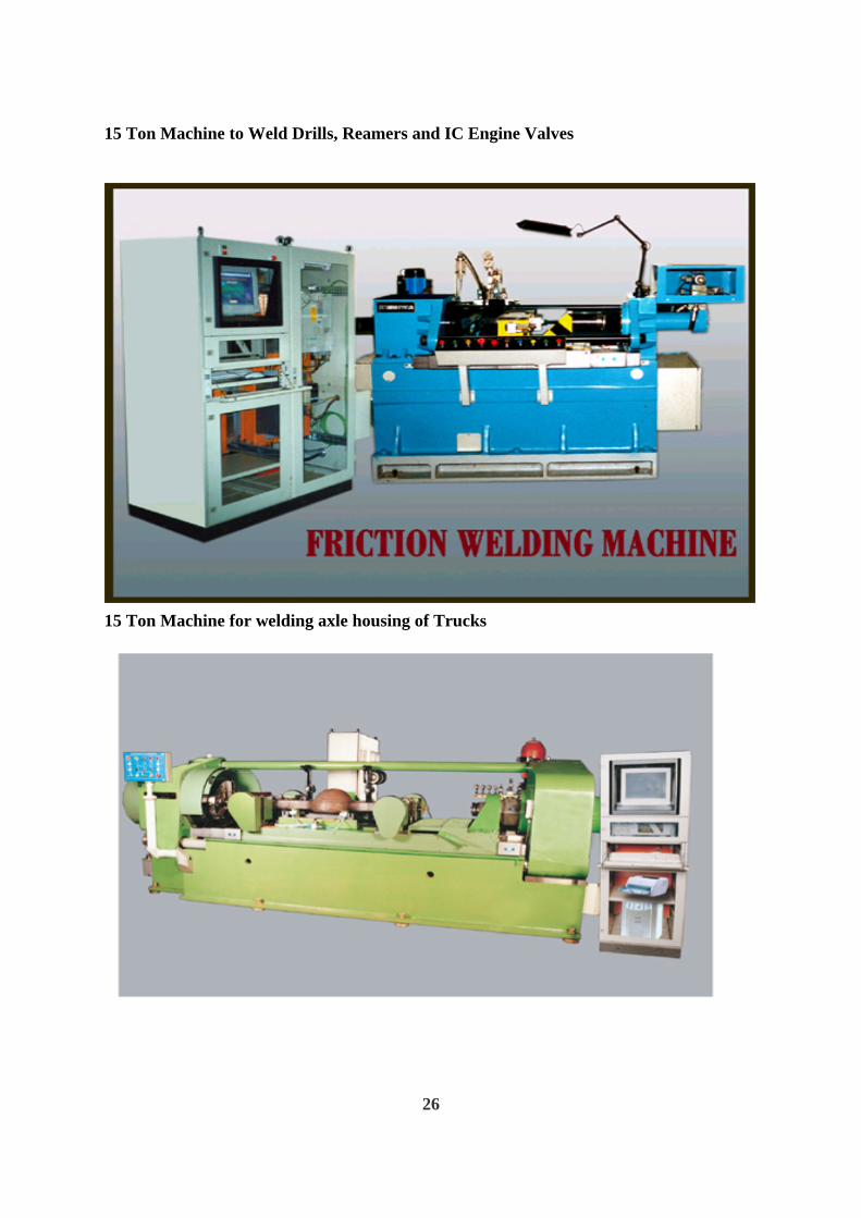
15 Ton Machine to Weld Drills, Reamers and IC Engine Valves
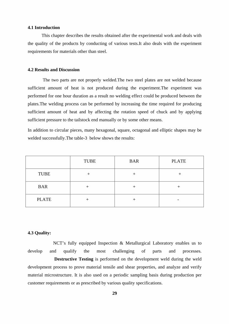
15 Ton Machine for welding axle housing of Trucks
26

6 Ton Vertical friction Welding machine to weld IC Engine valve
3.5 Capacities of a recommended welding machine:
The table-2 below illustrates the capacities of each size friction welding machine.
Welder
Size
Weld Area
(Min/Max.")
Rod
Capacity
(Min/Max.")
Tube
Capacity
(Min/Max")
Force
(LBS)
Chucking
(Max.)
Clamping
(Max.)
Part
Length
(Max.)
Spindle
RPM
(Min./Max.)
Flash
Removal
6 Ton .076 - .45 .250 - 0.75 .5 x .049
1,75 x .083 12,000 6" 15 Ton 72" 500 - 4000 Yes
10 Ton .11 - .785 .375 - 1.00 .625X .083
2.0 x .125 20,000 6" 20 Ton 36" 800 - 3000 Yes
15 Ton .2 - 2.0 .50 - 1.625 .75 x .049
3.0 x .25 30,000 8" 20 Ton 18" 2500 Yes
30 Ton .785 - 4.00 1.00 -2.25 1.0 x .083
4.0 x .25 60,000 10" 20 Ton unlimited 500 - 1600 Yes
45 Ton .785 - 6.00 1.00 -2.75 1.5 x .125
4.0 x .5 90,000 12" 34 Ton unlimited 300 - 1100 Yes
60 Ton 1.75 - 9.00 1.5 - 3.00 2 x .125 4.0
x .75 120,000 12" 50 Ton unlimited 300 - 1100 Yes
27

Pictured below, this typical 55 ton continuous drive friction welder is
specifically designed for job shop applications. The machine is equipped with two hydraulic
cylinders (4" and 8") providing maximum versatility to weld a wide range of parts from 0.5 to
6 square inch weld surface.
A variable speed DC drive provides capability for controlled energy input during
spindle deceleration. This machine is also equipped with a flash removal system. A state of
the art microprocessor based controller provides precise program development.
Individual weld quality is documented by recording all critical weld parameters for a
permanent record of force, displacement and spindle RPM.
28

Chapter 4
RESULTS AND DISCUSSION
4.1 Introduction
This chapter describes the results obtained after the experimental work and deals with
the quality of the products by conducting of various tests.It also deals with the experiment
requirements for materials other than steel.
4.2 Results and Discussion
The two parts are not properly welded.The two steel plates are not welded because
sufficient amount of heat is not produced during the experiment.The experiment was
performed for one hour duration as a result no welding effect could be produced between the
plates.The welding process can be performed by increasing the time required for producing
sufficient amount of heat and by affecting the rotation speed of chuck and by applying
sufficient pressure to the tailstock end manually or by some other means.
In addition to circular pieces, many hexagonal, square, octagonal and elliptic shapes may be
welded successfully.The table-3 below shows the results:
TUBE BAR PLATE
TUBE + + +
BAR + + +
PLATE + + -
4.3 Quality:
NCT’s fully equipped Inspection & Metallurgical Laboratory enables us to
develop and qualify the most challenging of parts and processes.
Destructive Testing is performed on the development weld during the weld
development process to prove material tensile and shear properties, and analyze and verify
material microstructure. It is also used on a periodic sampling basis during production per
customer requirements or as prescribed by various quality specifications.
29

Non Destructive Testing is a very successful method NCT uses to verify stock
material integrity as well as finished products. Ultrasonic Inspection methods can verify bond
integrity as well as internal material flaws such as laminations or voids.NCT offers a variety
of non-destructive testing methods, including: ultrasonic, dye penetrant and flourescent
penetrant.
Weld Parameter Monitoring assures weld quality by monitoring all crucial
process parameters with limits and alarms to guarantee process integrity, repeatability, and
quality.
4.3 Varying parameters:
Suggested parameters for a variety of metals and combinations of metals is provided in
Table 4:
TABLE 4 ______________________________________ Heating Weld P..sup.(1) P..sup.(2) Time.sup.(3) Energy.sup.(9) ______________________________________ 1. Carbon Steel.sup.(4): 5,000 5,000 7 24-30,000 2.Stainless Steel: 7,500 7,500 15 30,000 3.Carbon/Stainless Steels: 7,500 15,000 10 30,000 4.Tool Steel.sup.(6) 15,000 20,000 10.sup.(8) 40-50,000 5.Copper.sup.(7) 5,000 10,000 18 10,000 6.Aluminium.sup.(7) 4,000 6,500 6 15-18,000 7.Titanium.sup.(6-4) 8,000 12,000 7 15-20,000 8.Aluminium/Stainless 5,000 15,000 5 20,000 9.Copper/Aluminium 5,000 15,000 3 20,000
30

.sup.(1) Pressure in p.s.i.
.sup.(2) Pressure in p.s.i.
.sup.(3) Heating phase in seconds
.sup.(4) AISI 1010, 1020, 1030, 1045 and similar
.sup.(5) Series 300 and 400
.sup.(6) Type T1 and similar
.sup.(7) Alloying can substantially alter parameters
.sup.(8) Postweld treatment required
.sup.(9) Energy in Ft. Lbs.
The values in Table I are based on an orbital path having a period of 60 Hz, and eccentricity
of 0.125 inches (3.175 mm); during the heating phase, the orbits are 180 degrees out of phase,
and are brought into phase, and the relative motion stopped, within 100 milliseconds. The
parameters set out in Table I provide general guidelines.Good weld properties will result over
a broad range of variables. The weld energy input to the weld joint, the heating pressure and
heat cycle time are all varied to control the breadth of the heating zone on either side of the
weld joint. The weld pressure and energy input dictate the weld flush volume. Particularly
when welding dissimilar alloys, the time should be as short as reasonable to minimize
diffusion at the interface.
For most metals, little surface preparation is required, although major features, such as mill
scale and the like, are desirably removed before joining. At the times and temperatures
involved, surface coatings, lubricants and corrosion inhibitors and the like will be destroyed
and removed, and it is not strictly necessary to remove such materials, although it is generally
preferred that the surface be clean, dry and bare metal if such conditions can be reasonably
achieved.
The surfaces to be joined as subjected to the friction heating will be considerably abraded,
smoothed and altered by the operation. There is no requirement for conditioning the surfaces
in preparation for welding other than the removal of gross imperfections.
Heat build-up and temperature rise at the surface of the parts is generally quite rapid. As a
general matter, it is ordinarily desirable to operate under conditions which minimize the time
required to attain suitable welding temperature to limit the time for heat transfer and the
potential for heat distortions within the parts and to limit the energy input required.
31

4.3 Weldable Material Combinations:
Table -5
This chart shows only a portion of known joinable materials & combinations and does not
imply that materials not listed are not joinable.
32

Through manipulation of deceleration times and forge force ramp up time, welds can be
made ranging from near Inertia Friction welds to classic Direct Drive Friction Welds.
Fig-6
4.4 Determination of welding parameters and statistical design of experiment
Optimum friction (Pf) and upset pressures (Pu), and friction times (tf) values were determined
by optimization process. Starting values for pressures were selected among those of
recommended in related literature for such steel of the presented study (N.N., 1981). This
process is explained later.
The basis of this approach is the assumption of a simplified linear model for the optimization
parameter η given by η=β0+β1x1+b2x2+…, where x1, x2,… are the factors on which η depends
and β0, β1, β2,…, represent the “true” values of the corresponding unknowns. From the results
of an experiment comprising a finite number of trials, one can arrive at sample estimates of
the coefficients, β, which are then usually fitted into a linear regression equation of the type
y=b0+b1x1+b2x2+…, where y is the response function and bs are the “estimated” values of the
βs. In simple terms, each coefficient represents the influence of the corresponding factor on
the quality of the weld expressed by the optimization parameter.
33
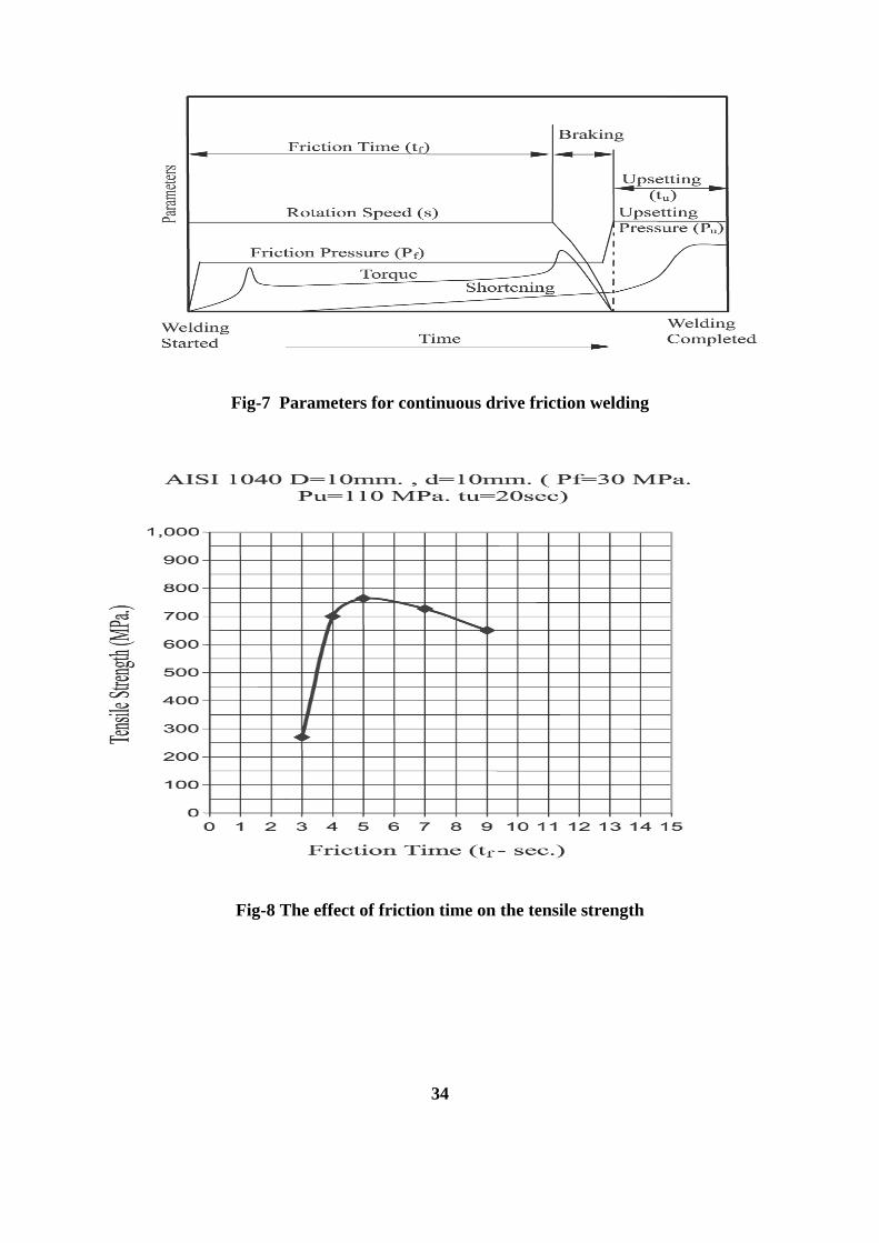
Fig-7 Parameters for continuous drive friction welding
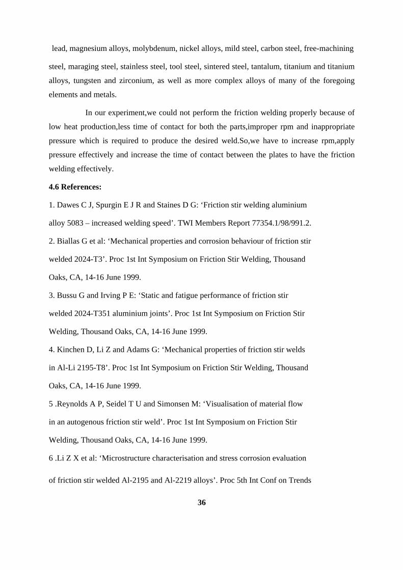
Fig-8 The effect of friction time on the tensile strength
34

Fig-9 Effect of friction time on joint tensile strength (material: AISI 1040, Pf�=�30�MPa, D/d=3)
4.5 Conclusion:
In general terms, the present invention is dependent on relative motion where
both faces of the weld joint are in motion during the heating phase of the operation, which
motions are brought into phase when the conditions of the joint are appropriate. While both
will continue in motion, at least for a brief period, the relative motion between the parts is
stopped by virtue of synchronizing the motions so they are in phase and identical. The change
of phase of the motions of the mating parts can be accomplished with far greater precision
and speed than are possible when alignment of the parts is dependent on stopping the motion
of one or both the parts.
In general terms, the present invention is applicable to all weldable materials, and
includes a few materials not ordinarily joined by welding techniques. These materials include
aluminum and a broad variety of aluminum alloys, brass, bronze, metallic carbides, such as
tungsten and titanium carbides, cobalt based alloys, columbium, copper, cupronickel alloys,
35
lead, magnesium alloys, molybdenum, nickel alloys, mild steel, carbon steel, free-machining
steel, maraging steel, stainless steel, tool steel, sintered steel, tantalum, titanium and titanium
alloys, tungsten and zirconium, as well as more complex alloys of many of the foregoing
elements and metals.
In our experiment,we could not perform the friction welding properly because of
low heat production,less time of contact for both the parts,improper rpm and inappropriate
pressure which is required to produce the desired weld.So,we have to increase rpm,apply
pressure effectively and increase the time of contact between the plates to have the friction
welding effectively.
4.6 References:
1. Dawes C J, Spurgin E J R and Staines D G: ‘Friction stir welding aluminium
alloy 5083 – increased welding speed’. TWI Members Report 77354.1/98/991.2.
2. Biallas G et al: ‘Mechanical properties and corrosion behaviour of friction stir
welded 2024-T3’. Proc 1st Int Symposium on Friction Stir Welding, Thousand
Oaks, CA, 14-16 June 1999.
3. Bussu G and Irving P E: ‘Static and fatigue performance of friction stir
welded 2024-T351 aluminium joints’. Proc 1st Int Symposium on Friction Stir
Welding, Thousand Oaks, CA, 14-16 June 1999.
4. Kinchen D, Li Z and Adams G: ‘Mechanical properties of friction stir welds
in Al-Li 2195-T8’. Proc 1st Int Symposium on Friction Stir Welding, Thousand
Oaks, CA, 14-16 June 1999.
5 .Reynolds A P, Seidel T U and Simonsen M: ‘Visualisation of material flow
in an autogenous friction stir weld’. Proc 1st Int Symposium on Friction Stir
Welding, Thousand Oaks, CA, 14-16 June 1999.
6 .Li Z X et al: ‘Microstructure characterisation and stress corrosion evaluation
of friction stir welded Al-2195 and Al-2219 alloys’. Proc 5th Int Conf on Trends
36

7.Amontons, G. (1699), “De la resistance cause dans les machines”, Mem.Del’Academie
Royale, A,
8. Bowden, F.P., Tabor, D. (1950), Friction and lubrication of solids, Oxford University
Press, England.
9. Haile, J.M. (1997), Molecular dynamics simulation: Elementary methods, John Wiley
& Sons, USA.
10. Greenwood, J.A., Williams, J.B. (1966), “Contact of nominally flat surfaces”,
Proc.R.Soc.London, A 295 pp. 300.
11. Tomlinson, G.A. (1929), “A molecular theory of friction”, Philos Mag., vol.7, no.7,
pp.905-939.
12. Singer. I.L., Pollack, H.M. (1992), Fundamentals of friction: macroscopic and
microscopic processes, Kluwer, Dordrecht.
13. Vairis, A. (1997), “Investigation of frictional behaviour of various materials under sliding
conditions”, Eur. J. Mech. A/Solids, vol.16, no.6, pp. 929-945.
14.abinowicz, E. (1995), Friction and wear of materials, John Wiley &Sons, USA.
15. ASM Handbook, (1992), Friction, lubrication and wear technology, ASM, USA.
16. Vairis, A., Frost , M. (2000), “Modelling the linear friction welding of titanium blocks”,
Mater.Sci.Eng., A292, pp.8-17.
17. Vairis, A. (1997), High frequency linear friction welding, PhD thesis, University of
Bristol, England
18. Chaudhury, P., Zhao, D. (1992), Atlas of formability : Ti6Al4V ELI, National Center for
Excellence in Metalworking Technology, Johnstown, USA.
19. Filippov, A.E., Klafter, J., Urbakh, M. (2004), “Friction through dynamical formation and
rupture of molecular bonds”, Phys. Rev. Lett., vol.92, 135503.
20. Budakian, R., Putterman, S.J. (2000), “Correlation between Charge Transfer and Stick-
Slip Friction at a Metal-Insulator Interface”, Phys.Rev. Lett., vol.85, no.5, 1000.
21. Christakis, N. Patel, M.K., Cross, M., Baxter, J., Abou-Chakra, H., Tuzun, U. (2002),
“Prediction of segregation of granular material with the aid of PHYSICA, a 3D unstructured,
finite volume modeling framework”, Int.J.Numer.Meth.Fluids, vol.40, pp.281-291
37
Related Documents