_I_ I _ /'/ Final Report submitted to NATIONAL AERONAUTICS AND SPACE ADMINISTRATION - . i _ GEORGE C. MARSHALL SPACE FLIGHT CENTER, ALABAMA 35812 April 12, 1996 for Contract NAS8 - 38609 Delivery Order 135 entitled Study of Effects of Gravity on Crystallization by Guy A. Smith Senior Research Associate Gary L. Workman Ph.D. Principal Investigator Susan O'Brian Research Associate Materials Processing Laboratory Center for Automation & Robotics University of Alabama in Huntsville Huntsville, Alabama 35899 https://ntrs.nasa.gov/search.jsp?R=19960023890 2018-06-10T18:19:21+00:00Z

Welcome message from author
This document is posted to help you gain knowledge. Please leave a comment to let me know what you think about it! Share it to your friends and learn new things together.
Transcript
_I_ I _ /'/
Final Report
submitted to
NATIONAL AERONAUTICS AND SPACE ADMINISTRATION
- . i _
GEORGE C. MARSHALL SPACE FLIGHT CENTER, ALABAMA 35812
April 12, 1996
for Contract NAS8 - 38609
Delivery Order 135
entitled
Study of Effects of Gravity on Crystallization
by
Guy A. SmithSenior Research Associate
Gary L. Workman Ph.D.
Principal Investigator
Susan O'Brian
Research Associate
Materials Processing LaboratoryCenter for Automation & Robotics
University of Alabama in HuntsvilleHuntsville, Alabama 35899
https://ntrs.nasa.gov/search.jsp?R=19960023890 2018-06-10T18:19:21+00:00Z

Over the course of this research effort two primary tasks were accomplished. The
result helped in confirming the theory that the absence of gravity aids in preventing for
formation of crystallites in ZBLAN optical glass fiber. Secondly, an important step has
been taken in being able to draw fiber from a ZBLAN preform on the Space Shuttle.
Section 1 reports on the effort of confirming the effect gravity has on the formation of
crystallites in ZBLAN. Section 2 deals with the development of a sting system to initiate a
fiber draw by remote control during low gravity maneuvers aboard NASA's KC-135aircraft.
Section I
Worked Performed on the Glass Anealing Furnace
Introduction
ZrF4-BaF2-LaF3-ALF3-NaF (ZBLAN) optical fiber was flown on board NASA's KC-
135 aircraft to determine the effects of microgravity on crystal growth in this material.
Fiber samples were placed in evacuated quartz ampoules and heated to the crystallization
temperature in 0-g and on the ground in 1-g. The 1-g samples had many regions of
crystallites, while the 0-g samples showed no evidence of crystallization.
Mid infrared fiber optics have many promising applications in both the industrial and
military sectors. These include ultralong, repeaterless, transcontinental and transoceanic
links, nuclear radiation resistant links, high capacity wavelength multiplexed fiber optic
devices, remoting of infrared focal planes, infrared laser devices, infrared power delivery,
long-length fiber optics sensor systems and nonlinear optical systems. _ Heavy metal
fluoride glasses have shown the most promise to date. The most stable heavy metal
fluoride with respect to crystallization appears to be those in the ZrF4-BaF2-LaF3-AIF3-
NaF family, commonly referred to as "ZBLAN" glasses. 2
Intrinsic and extrinsic processes limit light propagation at low powers in ZBLAN. 3
Intrinsic properties include band gap absorption, Rayleigh scatter and multiphonon
absorption. Extrinsic processes include impurities such as rare earth and transistion metal
ions and crystallites formed during preform processing and fiber pulling. The theoretical
loss coefficient for ZBLAN is 0.001 dB/km at 2 microns. Achieving this lower limit is
hampered by both the intrinsic and extrinsic processes.
All of the intrinsic processes and extrinsic impurities can be controlled through
processing of the initial raw materials and in preparation of the glass preform. The
devitrification of ZBLAN is due to a narrow working range and low viscosity at the
pulling temperature. 4 These two factors make this glass unstable and prone to
crystallization.

Microgravityprocessingoffersthepotentialto minimizetheselossesin ZBLAN glass.5Improvedpurityof rawmaterialsandthepossibilityof containerlessprocessinginmicrogravityin thefutureareexpectedto expandglassformingregionsandminimizetheformationof microcrystallitesduringsynthesisof theglass.5 Microgravityprocessingalsooffersthepotentialof minimizingphaseseparationandcrystallizationduringsubsequentglassformingsteps.5 Fluorideglasssynthesishasnotbeenattemptedin microgravitytodatedueto thecorrosivenatureof theprocess.5
Canadianworkhasindicatedtheenhancedcrystallizationof certainZBLANformulationsunder2-gandnoevidenceof crystallizationin 0-gusingaT-33 aircraft.5'6
Experimental
Two meter lengths of ZBLAN optical fiber were obtained from two different sources."
The protective polymer coating was removed chemically, and then the fibers were cut into
25mm lengths. Individual fibers were placed in an evacuated quartz ampoule and sealed.
Fiber diameters were nominally 300 microns.
A fiber annealing furnace (FAF) was designed and constructed for use on the KC-135
aircraft (figure 1). The FAF consists of a preheat furnace, annealing furnace and a quench
block. The sample is translated manually through each component using a stainless steel
push rod. In operation, a single quartz ampoule is placed at the end of the push rod, and
then translated into the preheat furnace for a period of two minutes. This allowed the fiber
to reach a temperature of 250°C. Then, during the microgravity portion of the aircraft
parabola the ampoule is translated into the annealing furnace for 15 seconds allowing the
sample to reach a temperature of 415°C. This temperature is approximately 20°C above
the crystallization temperature of ZBLAN. At the end of 15 seconds the ampoule is
translated into the perforated brass quench chamber. Water was then used to quench the
ampoule via a plastic 60 cc syringe. Cooling rates were generally around 400 C/sec.
Ground tests were performed to determine the time necessary to reach the nucleation
temperature and to run 1-g studies. A thermo-couple was inserted into a glass ampoule
and translated into the preheat furnace until the temperature reached 250°C and then into
the annealing furnace until a temperature of 415°C was obtained. In this manner, the times
necessary for preheat and annealing during the parabolic manuever were established. Five
samples of each manufacturer's fiber were then heated at 1-g.
During the KC-135 flights ten samples of each manufacturer's fiber was heated during
the 0-g portion of the parabola. Actual gravity levels during the 20 to 25 second period of
0-g range in the 0.01 to 0.001 g level.
" Infrared Fiber Systems(Silver Springs, Md.) and Galileo Electro-optics (Sturbridge, MA.)
2

The processed ZBLAN samples were examined using optical microscopy, scanning
electron microscopy and EDX analysis.
Optical fiber communication offers an exciting alternative to traditional wire
communications. Extensive research over the past two decades helped in bringing down
the transmission loss in silica fiber close to its theoretical limit of about 0.2 dB/km.
However, the high density optical communication systems in the future would require
optical fibers with losses far below those of silica fibers. Many infrared transmitting
materials, such as heavy-metal oxides, halides, and chalcogenides, have the potential of
having losses below 0.01 dB/km cz3A_.Amongst these, heavy metal fluoride glasses based
on zirconium fluoride are most promising.
Fluorozirconate glasses have a broad transparency range, low refractive index,
small dispersion, low Rayleigh scattering, and ultra-low thermal dispersion. In addition to
fiber optics, they can be used in infrared remote sensing, laser power transmission, control
systems for nuclear power plants, and various other applications. They offer a great deal
of compositional flexibility, which could allow their properties to be tailored to a broad
range. Although the theoretically predicted loss factor in fluoride glasses is around 0.001
dB/km C_,the practical limitations in material purification brings this value up to around
0.02 dB/km.
Fluoride glasses have a narrow glass forming region. The large density difference
between different components could lead to rapid phase separation and crystallization in
these glasses under gravity. The microcrystallites formed in these glasses during synthesis
or subsequent processing give rise to undesired scattering and higher than expected losses.
Presently the losses obtained in these glasses are in the range of 1 to 100 dB/km, with best
reported values of 0.7 to 0.9 dB/km (6'7_.
Previous studies of this nature c' were incomplete in that the researchers observed
no crystallization during flight. The conclusions drawn from that set of experiments noted
that several variables, including the temperature profile were inadequately controlled for
good scientific observations. The results did suggest that nucleation of microcrystallites
does have a strong dependency on the temperature gradient at the solidification interface
and any experimental work in this area needs to have that parameter under control.
Synopsis of the Glass Annealing Furnace
The purpose of this KC-135 experiment is to determine the effects of gravity on
nucleation and growth of crystals in optical fiber. It is believed that in microgravity that
there will be an absence of nucleation and growth and that these phenomena will be
enhanced in the 2g portion of the parabola. The GAF will be used to anneal (not melt) the
fibers in either low or high gravity. During the annealing process the growth of crystals
maybe enhanced or retarded by the influence of gravity. The results of this experiment
will be used in the development of Space Shuttle experiment. This research is intended to
helpdevelopaprocessto improvethetransmissionpropertiesof commercialfiber opticcables.
Theopticalglassfiberswill besealedwithin aquartzampouleto preventdeteriorationfrom moisturewhilebeingheated.Theampouleis60mm longand3 mm indiameter.
Test Objectives
To process approximately 30 samples total, 15 in low-g and 15 in high-g. Results
of the effects of low and high gravity upon crystal nucleation will be determined in the
laboratory at MSFC, Alabama.
Test Description
For each run one quartz ampoule containing one 24 mm long optical grade quartz
fibers will be placed into the preheat furnace set to 300 ° C. At the appropriate time the
ampoule will then be pushed into the annealing furnace set to 400 ° C and allowed to heat
soak for approximately 10 seconds. Then it will be pushed into the quench chamber
where water will be sprayed onto it and rapidly quench the sample. Quartz is very
resistant to thermal shock at this low temperature, therefore the risk of the ampoule
shattering is very minimal. A 0.125" diameter stainless steel rod is used to secure the
ampoule and move or push the ampoule from one zone to the next in a straight line.
Equipment Description
The GAF is a relatively small package measuring 22"L x 10"W x 7.25"H and
weighs less than 25 pounds. Its basic components are two furnaces, a water quench
chamber and associated temperature control circuitry. The unit will be bolted down to a
framework assembly fabricated from AMCO Engineering Co. stock materials which will
act as a pedestal structure. This pedestal has flown twice in support of the KC-135 Fiber
Pulling Apparatus in the past. It's safety information is contained within documents
associated with the FPA experimental hardware and has already passed a JSC TRR.
The experiment processing area is contained within a Plexiglas housing and is
vented to the aircraft's overboard dump system. The dump system is utilized for two
reasons: (1) To provide a means of removing the 50 to 60 ml of quench water and (2) to
maintain a slight negative pressure within the housing in the unlikely event that one of the
sample ampoules should break. If an ampoule should break then no further action would
be taken during that particular flight and the experiment would be shut down and recycled
on the ground.
The electrical system is comprised of two temperature control systems - one for
each furnace. An Omega model CN 132 temperature controller will monitor the
temperature of the particular furnace and apply or remove power to the heating element
by controllinga InternationalRectifiersolidstagerelaymodelTD1225which is ratedto25 amps.Thereis only one7.5ampcircuit breakerswitchto controlpowerto theentiresystem.
To quench the ampoule a 60 cc plastic syringe located outside the Plexiglas
housing is connected via a plastic hose to the brass quench chamber located within the
housing. The syringe contains only pure water and does not utilize any type of needle.

©
II
,&
Structural Load Analysis
Two simplified case studies are presented dealing with the heaviest objects and the
associated mounting points. The first case deals with the two bolts that mount the entire
assembly (25 pounds) to the top of the support structure. This support structure has been
flown aboard the KC-135 in the past for use with the Fiber Puller Apparatus and is
referred to as the pedestal.
The second case shows an analysis of the heaviest object (the annealing zone
furnace) and its associated hardware to the base plate. All total this item weighs 3.1
pounds and is the heaviest single item contained within the system.
It is our contention that these two studies represent the worst case conditions with
this hardware. It should be pointed out that the reactive moment arm is included in the
analysis with the center of gravity for the assembly at 3.5 inches up from the base plate, 9
inches from the left side and 5.5 inches from the front edge. It is assumed that the 9 g
load is applied in the X and Z directions simultaneously along with a 2 g load in the Y
direction.
Figures 2 and 3 provide sketches of the AMCO framework pedestal and where the
GAF system is located with respect to the pedestal. The pedestal was originally designed
to support the Fiber Puller Apparatus which weighed 146 pounds, therefore no structural
analysis is considered necessary for this application since the GAF only weighs 25 pounds.
7

i
iI
!o,,$L'L_

z
.ICILl "_
(/JIIJ
/I
| III
c_
0
_4
o,1,_
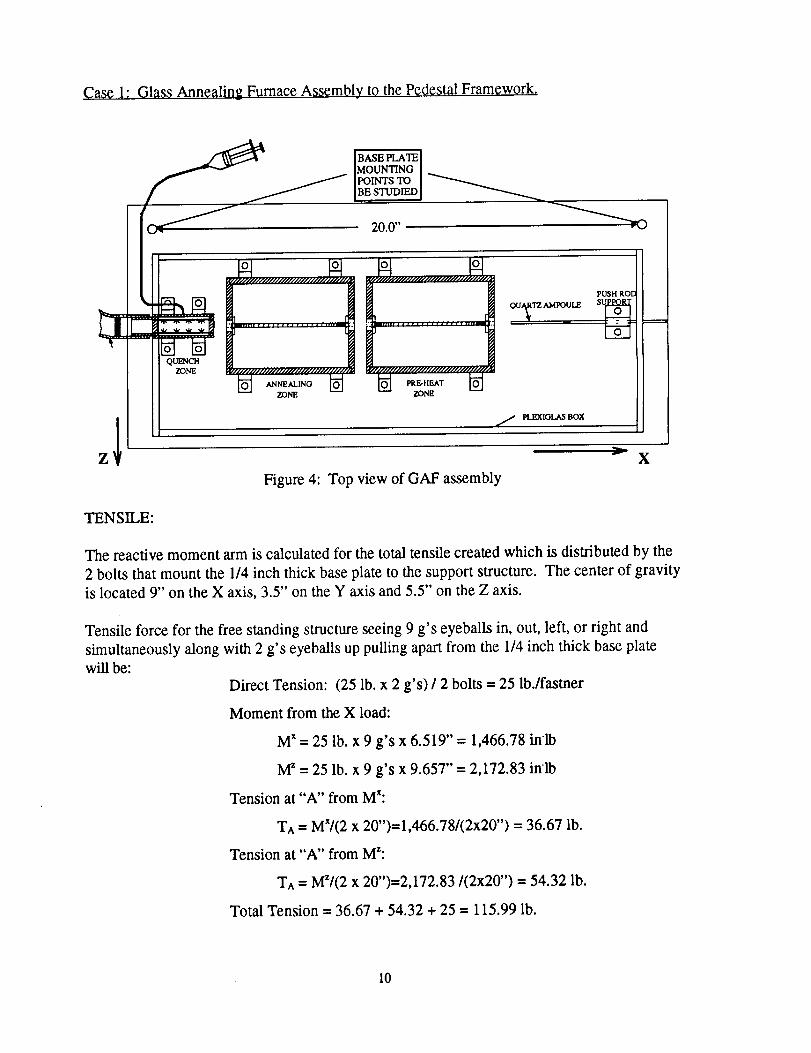
Case 1: Glass Annealing Furnace Assembly tO the Pedestal Framework,
QUENCHZONE
Figure 4: Top view of GAF assembly
TENSILE:
The reactive moment arm is calculated for the total tensile created which is distributed by the
2 bolts that mount the 1/4 inch thick base plate to the support structure. The center of gravity
is located 9" on the X axis, 3.5" on the Y axis and 5.5" on the Z axis.
Tensile force for the free standing structure seeing 9 g's eyeballs in, out, left, or right and
simultaneously along with 2 g's eyeballs up pulling apart from the 1/4 inch thick base plate
will be:
Direct Tension: (25 lb. x 2 g's) / 2 bolts = 25 lb./fastner
Moment from the X load:
M x = 25 lb. x 9 g's x 6.519" = 1,466.78 in'lb
M z = 25 lb. x 9 g's x 9.657" = 2,172.83 in'lb
Tension at "A" from M':
T^ = MX/(2 x 20")=1,466.78/(2x20") = 36.67 lb.
Tension at "A" from MZ:
TA = M'/(2 x 20")=2,172.83/(2x20") = 54.32 lb.
Total Tension = 36.67 + 54.32 + 25 = 115.99 lb.
10

The3/8" stainlesssteelboltsusedareratedto 13,798lb. each.Theforceseenat 2 g'seyeballsup is 113lb. poundsperbolt. Therefore,eachbolt is 13,798/116= 119timesstrongerthanrequiredfor atensileforceof 2 g's eyeballsupalongwith 9g's eyeballsin, out,left, or right. This valueis approximatesinceit doesnot takeintoaccountshearor pre-loadingof thebolt.
SHEAR:
Forthis case,primaryshearisconsideredfor all boltsthatattachthebaseplateto thetopofthepedestalframework. Shearstressseenacrossthemountingboltsat 9g's eyeballsin, out,left, or rightwill be:
DirectShear:(25 lb. x (92g's x 92g's)la) / 2 bolts = 159.10 lb./fastner
Total Shear = 159.10 lb.
Each bolt sees 159.10 pounds of direct shear force. The 3/8" stainless steel bolts used are
rated to a shear strength of 8,279 lb. each. Therefore, each bolt is 8,279/159 = 52 times
stronger than the shear forces expected at 9 g's eyeballs in, out, right or left. This value is
approximate since it does not take into account shear or pre-loading of the bolt.
11

Case 2: Annealing Zone Furnace to the Base Plate
O
o 0
O
I
NJSI, I ROD
Sl..II'I_ORT
FLEXIOLAS BOX
Figure 5: Top view of GAF assembly
The reactive moment arm is calculated for the total tensile created which is distributed by the
four 10-32 stainless steel screws that attach the furnace mounts to the base plate. The center
of gravity is located 2.5" on the X axis, 2" on the Y axis, and 2" on the Z axis.
Tensile force for the free standing structure seeing 9 g's eyeballs in, out, left, or right and
simultaneously along with 2 g's eyeballs up pulling apart from the 1/4 inch thick base plate
will be: (Assume moment arm is conservatively 4")
Direct Tension: (3.1 lb. x 2 g's) / 4 bolts = 1.55 lb./fastner
Moment from the X load:
M x -- 3.1 lb. x 9 g's x 2" = 55.8 in'lb
M z = 3.1 lb. x 9 g's x 4" = I 11.6 in'lb
Tension at "A" from MX:
T^ = MX/(2 x 3.75")= 55.8/(2x3.75") = 7.44 lb.
Tension at "A" from M_:
T^ = M_/(2 x 5")= 111.6/(2 x 5") = 11.16 lb,
Total Tension = 7.44 + 11.16 + 1.55 = 20.15 lb.
The 10-32 stainless steel screws used are rated to 3600 lb. each. The force seen at 2 g's
eyeballs up is 20.15 pounds per screw. Therefore, each screw is 3600/20.15 = 178 times
stronger than required for a pure tensile force of 2 g's eyeballs up simultaneously along with 9
12

g's eyeballsin, out,left, or right.Thisvalueisapproximatesinceit doesnot takeinto accountshearorpre-loadingof thescrew.
SHEAR:
For thiscase,primaryshearisconsideredfor all boltsthatattachthefurnaceto thebaseplate.Shearstressseenacrossthemountingboltsat9 g's eyeballsin, out,left, or right will be"
DirectShear:(3.1 lb. x (92g's x 92g's)_a)/ 4 bolts = 9.86 lb./fastner
Total Shear = 9.86 lb.
Each 10-32 stainless steel screw sees 9.86 pounds of direct shear force. The screws used are
rated to a shear strength of 2,160 pounds each (60% of the tensile). Therefore, each screw is
2,160/9.86 = 219 times stronger than the shear forces expected at 9 g's eyeballs in, out, right
or left. This value is approximate since it does not take into account tensile or pre-loading ofthe screw.
13
Electrical Load Analysis
This system uses 120 volts 60 Hz. AC only. A single 30 foot long 18 gauge power
cord provides the AC power interface to the experiment. Total load for the experiment will
be 5.0 amps maximum during the furnace heat up and will subsequently become intermittent
once the furnace has reached temperature. The temperature controllers use timed
proportioned control of the power to regulate temperature. Maximum current draw is limited
by the resistance of approximately 50 ohms for each heating element.
The Omega model CN132 temperature controller maximum power draw is 2.5 watts
and is internally protected with a 100 milliamp fuse.
On the following page is Figure 6 which identifies the AC power circuits, main power
switch which is also a circuit breaker and wire gauges. Except for the power cord all wiring is
TFE insulation and rated to 175 ° C. The 30 gauge thermocouple wire is insulated with glass
braid insulation.
14

t_
E
c_
°lm4
c
P

In Flight Test Procedures
During level flight one quartz ampoule will be removed from the supply case and
inserted into the end of the push rod. With the access door closed, the ampoule will be
loaded into the preheat furnace set at 300 ° C and allowed to heat soak for at least 5
minutes. Upon entering a low or high-g period the ampoule will then be pushed or loaded
into the annealing furnace set to 400°C and allowed to heat soak for 10 to 15 seconds.
At the end of this time period the ampoule will then be pushed into the water quench
chamber. Here the 50 to 60 milliliters of pure water will be sprayed onto the ampoule by
the plastic syringe and thus rapidly cool down the sample.
To recycle the experiment a new ampoule and plastic syringe filled with water will
be installed during level or high-g flight.
Parabola Requirements
During sample loading and unloading procedures a period of 1 to 2 minutes of
high-g or level flight is all that is required. Only one parabola is needed to process anyone
sample and can occur anytime after the required preheat period. It is hoped that 5 to 10
samples per flight can be processed. There are only two test support requirements: 1. The
110 Volt AC, 60 Hz. aircraft power be supplied at least 30 minutes prior to take off to
allow the furnaces to heat up, and 2. The overboard dump be available during the flight
period. The air flow rate of the dump will be meter through the use of a ball valve and
will not be operated in a full flow condition.
Results and Discussion
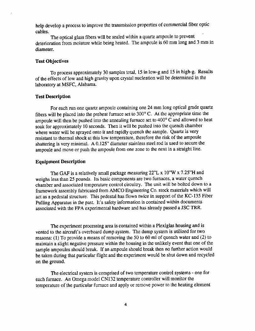
An electron micrograph of an as-received fiber is shown in figure 2. in figure 3, a fiber
processed in 0-g is shown. Figure 4 shows a fiber processed in 1-g. It is obvious
crystallization has occurred in the fiber processed in 1-g. No signs of crystallization were
seen in any of the fibers processed in 0-g, while all fibers processed in 1-g showed signs of
crystallization. Figure 5 is an EDX spectrum of a 0-g processed fiber. The hafnium present
is due to the fiber cladding. In contrast, figure 6 is an EDX spectrum of a fiber processed
in 1-g. It is high in barium content as compared to the 0-g spectrum. Metastable and stable
phases of beta-BaZrF6 and beta-BaZr2F10 along with the higher temperature forms have
been identified by other authors. 2'4 The crystals seen in figure 4 are most likely one of
these phases.
From the above results, it appears that microgravity would be beneficial to producing
ZBLAN optical fibers. This is somewhat intuitive since ZBLAN has a low viscosity near
the eutectic and the difference between the crystallization temperature and the glass
transistion temperature is less than 100°C. Both of these reasons have been cited by
numerous authors as causes for ZBLAN's tendency toward crystallization. Both of these
conditions plus the wide variation in atomic weights in ZBLAN would contribute to
16

buoyancyconvectionwhich is suppressedin microgravity.Therefore,onecouldexpectlittle or nocrystallizationif thefiber couldbeproducedin amicrogravityenvironment.
Figure4. SEM micrographof ZBLAN fiberprocessedin I-g, 80Xmagnification.
9-Hag-1595 BS:II:51
Bg ZBLRN FIBER1 OVERALL
Zr'
.,
It Iz 13 I 4 ls 16 I? le 19e.nnn Range- 1ft. Z3H keV 1H.l16
lntegrnl O = 164063
17

Figure 5. EDX Spectrum of low-_ processed ZBLAN Fiber.
9-Hay-lg95 1B:_5:19
tg ZBLRN FIBER, CRYSTAL
HF
ZP
At
0 jHaM S
_0--I_I 12 13 14
4-- B, BAB Range -
Bit
HF
Ba
HF
15 16 I 7 I B Ig1B.23B keV IR.I1B 4
lntegPal B ,, ei_lT5
Figure 6. EDX spectrum of 1-g processed ZBLAN fiber.
d(_PN" , ,,
UMT
_HICLE OUTER
- C/LSINO 29.0"
: ,am]!
-" .I
Figure 7. Schematic of sub-orbital rocket payload to be flown on Conquest 1 in February1996.
18

Section II
Work Performed on the Fiber Pulling Apparatus
Introduction
A reduced gravity fiber pulling apparatus, henceforth FPA, has been constructed in
order to study the effects of gravity on glass fiber formation. The apparatus was
specifically designed and built for use on NASA's KC-135 aircraft. During this period of
performance the FPA was modified to include a remotely controlled sting mechanism by
which the operator could initiate a draw process from a glass preform. One flight has
been completed to date during which ZBLAN glass fiber was successfully produced in a
simulated zero gravity environment.
Initially the FPA was developed under contract NAS8-36955, Delivery Order 113
over the period of March through September of 1991. At the end of that six month period
it was determined that several improvements could be implemented into the apparatus to
aid in formation and study of micron diameter glass fibers. Hence, a follow on contact
was obtained to continue the research. One of the major problems in drawing a glass fiber
on the Space Shuttle is safety. Normally on the ground the draw tower operator will
allow a bead of softened glass to fall and thus initiate the draw process. However in the
absence of gravity this process will not work for obvious reasons. Hense a difference
method had to be developed. The result was the integration of a remotely controlled sting
apparatus into the existing FPA system. By developing this remotely controlled draw
initiation process the payload specialist will not be in contact with a hot surface or
material. The following provides the results of what has been accomplished.
Description of the FPA
Referring to figure 1, the FPA consists of a furnace and associated temperature
controller, fiber take up reel and servo motor, video camera, fiber quenching and cooling
system. These basic components are enclosed in a Plexiglas housing. Since this system
flies aboard the KC-135 safety requirements dictated a containment system. There is a
port for dry nitrogen gas so that the relative humidity of the apparatus can be reduced
during fiber drawing. A hygrometer is located on the inside rear wall which reads relative
humidity. The FPA is controlled by a data acquisition system. This system consists of an
IBM AT industrial grade computer with Metrabyte model DAS8 eight channel 12 bit A/D
board for recording data and controlling the servo winding motor and a video graphics
overlay board. Also mounted within the rack is a super VHS video recorder, video
monitor, keyboard, and associated control electronics. The video monitor displays the
image of the glass fiber as it is being drawn and overlays on it the graphical data. Thisdata includes three axes accelerometer data from a set of Sundstrand model 700
accelerometers, furnace and bushing orifice temperatures, fiber winding speed in cm/sec,
date and time.

Thefurnaceconsistsof abrasstubewoundwith Kanthanheatingwire encasedinaluminapottingcompoundandsubsequentlyin zirconiafelt insulation.Thefurnacehousingis madefrom 6061aluminum.Threeplatinum/rhodiumtypeSthermocouplesareplacedin thealuminatubeto measurethefurnacetemperature.Temperatureis controlledby aEurothermmodel818Sprocesscontrollerlocatedon thefront wall of theFPAPlexiglashousing.A watercooledring jacket is located just above the hot zone of the
furnace. This keeps the majority of the ZBLAN preform cool enought to prevent to
formation and growth of crystallites. A servo motor controlled translation system was
also fabricated. This provides a mechanism for the ZBLAN preform to be feed into the
hot zone of the furnace once the draw has been initiated.
FPA Operation
With the furnace at the proper temperature the ZBLAN preform is lowered into
the hot zone of the furnace. The furnace operates on 120 VAC and z5i226 -30 TD /SB 9mehot (mechanism) 0 TD (furnace (the) Tj 12016 0 TD (crystallites.) urrD (. Tj 12016 0 TDD (furnacD (z5i22maxim (type)lation) T3 0 TDD (is) Tjature.) Tj 65 0 TD type)l913 0 TD (the) Tj 18 0 TD (furnac7) Tj 38 0 TD (operat911 0 TD (lowereB 9me) T1000°C ( (mechanism) 0l91 (furnach0 Tv (locateD (hot) D (the) Tj 17 0 T 0 TD (D (is) Tm) Tj 37 TD (preform) Tj 41D (furnac7) Tj 38n0 0 ljust) Tj 21 0 j 60 0 TD (the) Tj 17 0 T (lowerej 17 0 T400°C. Tj 12016 0 TDD (furnace) Tj 39 0 TD (consists) Tj 4i -393 -13 TD (als8ed) Tj 35 acTD (Dbl type)lj 17 0 TD r TD is) Tj 11 0 TDmechanism) Tj do (the) j 13 0 TD 0 TD (on) Tj 15 0 TD (the) Tj 17 0 TD (proper) Tj 34 topfurnace.) Tj 4 (the) Tj 18 0 TD (FPA) Tj 0 0 TD . Tj 1num/rhodiDurD (compound) Tj 5he (the) Tj 22 0 j 17 0 Tj 18 0 TD (front) Tj 26 0D (Operation) Tj canVAC) Tj 28 0 Tb -412 -14 TD (plac0d) Tj 35 0urg (just) Tj 21 0 wD (the) Tj 18 0 Tdryfront) Tj 26 0 0rog (initirm) Tj 41g (been) Tj 24 0 whichcontrolledcompouj 0 0 TD -394
furnacetemperTj 21 0 (lowered) Tj 42 0 gramm (just)6mtheof(been)5 13 0 TD (the) Tj 18 0 Tincrea(D (is) T -30 TD /SBs81d) Tj 35 (the) Tj 18 0 Tdecrea(D (is) Tm) Tj 37 0pD (.temperTj 21 0 D (s(the) Tj 17 0 TincremD ((been)5 13 0 TDar(proper) Tj 34 51 0 TD (translation) Tby17 0 Tj 18 0 TD (front)) Tj 34 UP/DOWNthe) Tj 17 0 Tar TD0 TD /S 13 0 TD 0 TD (on) Techanism) 0 TD (4 0 TD (120) Tj 18 0 TD (front)) Tj 34 compuD (coolejature.) keyboar (This) 016 0 TDD (furnacj 17 0 Tmaxim (type)l0) Tj 39windD (is) Tjj 17 0 TspD (into)3j 17 0 T (lowereB 9me) T1000thez5i22TD -394 -14 TD (fur71d) Tj 35 incremD ((been)5ion) Tj canVAC (into) mh(the) Tj 17 0 T (the) Tj 18 0 Tmechanism
growthinto
the draw properoffurnacD (z5i22reelfurnacD (z5i22 (lowered) Tj 42mechanism) Tj sixthe) Tj 17 0 TinchofthefurnacTapethefurnac7Thecompouj 0 0 TD -394furnac7locattion(been)4j 17 0 T (the) Tj 18 0 Ttwogrowth
fur72dThefurnac7initi3j 17 0 T TD -3972j 17 0 TD (furna -14 TD (plac6d) Tj 35 feltgrowt Tj 24 0 padslocattj 18 0 Tthr TD into) j 17 0 Twhichcontroj 17 0 TD (furnac7) Tj 38glasslocattionloweredtransl3smpl380dcompouj 0 0 TD -394locattionlocattj 0 0 je(the) Tj 17 0 T (been) m
fur79discoole -14 TD (fur66d) Tj 35 Tddslocattj 18 0 Tth(front)eslocattioncompouj 17 0 Trecord (into) 5 0 0 (120) Tj 18 0 TD (front)es
als92dthefurnac7locattionlocattj 0 0 i(the) T0transom (locat32ture.) Tothelocat -14 TD (pla04d) Tj 35 D -397Tj 18 0 Tpa(sthe) Tj 18 0 TTDr TD (The) TionlowerT4front8d Tj 12j 17 0 Ti -393 -13 TD (als89d) Tj 35 circulTD (on) T50 18 0 TTDr TD isfurnac7transomfurna -14 TD (pla02d) 5r -394tioncompou7Tj 26 0 echanismfurnacismlocattj 18 0 T (lowered) Tj 42coollowerT4als86dloweredlocattj 18 0 T (lowerej 28 0 Tb D (compouj 17 0 T0roduc (into) 7) Tj 38 romOperation) Tj echanismals74dfront

Quenchingthefiberrapidlyhelpspreventnucleationeventswhichcanadverselyaffectfiber properties.Theotheroptioninvolvesusingdrynitrogengasto quenchthefiber. Inthismethod,abrassannuluswith a 13mmdiameterhole in thecenterandtwenty0.7mmholesarrangedaroundtheinsideperimeteris usedto directnitrogengasonto thefiber asit ispulled. This notonlyquenchesthefiberbutaidsin thedrawingprocess.
During areducedgravitymaneuverin theKC-135aircraft,theaccelerationduetogravity canbeaslow as0.001gandashighas2g. Thus,theFPAwasconstructedtowithstandtheloadsseenduringtheparabolicmaneuvers,aswell as9gemergencycrashlandingloads. Thisreason,pluson-boardsafetyconsiderations,iswhatdictatedoveralldesignsof theFPAsystem.
Results
Two types of ZBLAN glass material were used in this investigation: one provided
by Infrared Fiber Systems and the other by Galileo Electo-Optics. Since the purpose of
this test flight was to determine the effectiveness of initiating a draw by remote control the
preform samples provided were the remnants of previous runs by the two companies. The
left over preforms provided ample material to test the new design.
During the KC-135 flights several successful sting initiated draws were completed
thus proving the concept that a draw could be initiated by remote control. This provided
an important step in being able to accomplish the proposed research on the Space Shuttle
and International Space Station Alpha.
Future Work
The next step in this research will be to fly samples of ZBLAN on a sub-orbital rocket
flight. This experiment will have the advantage of providing 5 to 7 minutes of
microgravity. Thus, a better understanding of the effects of microgravity on crystallization
will be possible. Figure 7 shows the payload which will be flown in February 1996 on the
University of Alabama in Huntsville managed Conquest 1 rocket. ZBLAN fibers will be
placed in evacuated quartz ampoules and heated above the crystallization temperature
during the microgravity portion of the rocket flight. Samples from each company will have
DTA performed to determine their exact crystallization temperature. Past experience has
shown this temperature to range from 385 ° to 394°C. The samples will be quenched
below the glass transformation temperature before the rocket sees any gravity forces upon
its decent to the ground.
Two shuttle mid-deck locker experiments are also planned. In the f'trst, ZBLAN
preforms will be heated to 800°C for 2 hours to dissolve all crystals and then rapidly
quenched to below the glass transition temperature. The preforms will then be annealed at
300°C to remove any residual stresses. From some of the preforms optical fibers will be
pulled on the ground using a conventional drawing tower to see if the attenuation
coefficient has been lowered. The remaining preforms will be pulled on the second shuttle

flight usinga fiber pulling apparatus as shown in figure 8. The results of this research will
determine the future course for the possible commercial production of ZBLAN fiber on
the International Space Station.
References
1. D.C. Tran, G.H. Sigel and B. Bendow, "Heavy Metal Fluoride Glasses and Fibers: A
Review", J. of Lightwave Tech., LT-2, No. 5, 1984.
2. L. Boehm, K.H. Chung, S.N. Crichton and C.T. Moynihan, "Crystallization and Phase
Separation in Fluoride Glasses", SPIE Vol. 843, Infrared Optical Materials and Fibers V,
1987.
3. P. Clocek and M. Sparks, "Theoretical Overview of Limitations of Light Propagation in
Infrared Optical Fiber", SPIE Vol. 484, Infr0,red Optical Materials and Fibers III, 1984.
4. N.P. Bansal, A.J. Bruce, R.H. Doremus and C.T. Moynihan, "Crystallization of Heavy
Metal Fluoride Glasses", SP/E Vo1484, ibid.
5. S. Varma, S.E. Prasad, I. Murley and T.A. Wheat, Proceedings Spacebound 91,248,1991.
6. S. Varma, S.E. Prasad, I. Murley, T.A. Wheat and K. Abe, Proceedings Spacebound
92, 109, 1992.
Acknowledgments
The authors would like to express our sincere appreciation to Jeff Mullins of MSFC,
Robert Williams, Linda Billica and the rest of the KC- 135 crew at Ellington Air Field,
Texas for providing the capability to perform these experiments.
4
Related Documents